
Introduction

This Kit will teach you how to build the Turtle Robot.Assembling the Pirate’s mobile platform is straightforward — just follow the below instructions step-by-step.
Assemble Your Own Motor
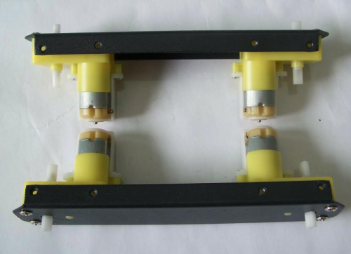
Look in your parts bag for eight long screws. These are used to fix and secure the motors in place. Place the motors in the correct alignment, then screw them into place as shown in the picture below.
Please note that washers and gaskets are also included in the parts bag. Washers can be used to increase friction, which helps fasten the motors into place. The gaskets help prevent the screw nuts from loosening and falling off due to the Pirate’s movements and collisions.


Soldering the Cables
Take the black and red wires out of the parts bag. Attach one black and one red cable (15 cm long) to each motor (4 motors in total). Then use your wire stripper to strip the insulation at both ends of the wires (make sure not to strip too much—refer to the pictures below). Next, solder the wires onto the pins affixed to the motors. Repeat the soldering process for all four motors.
Note:Pay attention to the correct locations of the red and black wires when soldering. Please consult the following photos for details.
image:Assemble Mobile Platform STEP2_1.png|1 image:Assemble Mobile Platform STEP2_2.jpg|2

Assemble the Romeo BLE controller
Look in your parts bag for three copper supports. Those 1cm-long supports are used to fasten the Romeo controller board. As shown in the picture below, there are three holes in the controller board. Place the three copper supports into the holes, then fasten them into place with the appropriate screws.


Assemble the Battery Box
Take out two countersunk screws (their heads are flat). Then follow the steps shown in the picture below and affix the battery to the car base.


Crafting the Power Switch
Batteries are the essential lifeblood of robots. To control power usage, we need to use a power switch: the switch turns off power when not in use, thus preserving electricity and battery life. Refer to the picture below before assembling and installing the power switch.
Please pay attention to the sequence of the gaskets and screw nuts when assembling the switch.

After assembling the switch, we want to start soldering its wires. Take some of the remaining wire leftover from before. Strip the wiring off both ends of the cables so that the inside of the wire is exposed (same process as with the motors before). We want to solder the exposed end of the wires to the pins on the switch. When soldering, it’s very important that we note the position of the switch’s pins.

Let’s do this step by step. a)Connect the switch to the battery charger. Pay attention to the exact location of both items.

b)Solder the red cables connecting the switch with the battery charger as shown in the picture below.

Here’s another picture to make things clearer.

c)Finally, take one red cable and one black cable. Attach one end of one cable to the negative pole of the battery charger and one end of the other cable to the positive pole of the battery charger. Then attach the other ends of both cables to the Romeo BLE controller.


Looking at this enlarged picture should give you a better idea of how the wires should be connected. After soldering, make sure to check and see if your wiring between the battery and Romeo controller is consistent from start to finish and matches with the above pictures.
Assemble the Car Base
Using eight M3x6mm screws, attach the side plates to the front and back bumper plates as shown by the diagram below.
Note: When tightening the screws during this step, make sure not to fully tighten the screws at first — this way, we can easily detach the top board in later steps should we need to make adjustments.

Then, re-attach the base plate to the body of the car as shown in the picture below.


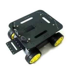
This is what the car base should like after it’s been assembled — remember to install the battery pack!
Connect the Motors with the Microcontroller Board
Now we need to the motors with the microcontroller board. Carefully follow the following diagram: the left motor’s red and black wires should be soldered into M2; the right motor’s red and black wires should be soldered to M1. Pay special attention to the battery pack: the black wire should be soldered into the wire port reading GND, while the red wire should be soldered in the wire port labeled VND. Use your screwdriver to loosen and tighten the wire ports — make sure these ports are fastened well once the wires have been inserted.
Note: Make sure the wires from one motor (i.e. the left motor) are soldered into the motor port. (i.e. the M2 port on the diagram below — do not solder one motor’s wires into two separate ports.)

After soldering the motor wires to the microcontroller board, we’re ready to attach the top plate to the base of the car. Before we attach the top plate, you have the option of attaching a sensor plate (see diagram below) — if you don’t plan to use sensors just yet, you can skip this extra step.


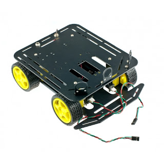
After attaching the top plate, your Pirate should resemble the picture below.

Find the four holes on the base’s top plate. Screw in the four M3x60mm Copper Standoffs, then attach the additional top plate as shown in the diagram below — use M3x6mm screws to affix the plate to the copper standoffs.

Toss some wheels on your Pirate and you’re ready to let it whip!


STEP2: Debug Motor
Sample Code
int speedPin_M1 = 5;     //M1 Speed Control
    int speedPin_M2 = 6;     //M2 Speed Control
    int directionPin_M1 = 4;     //M1 Direction Control
    int directionPin_M2 = 7;     //M1 Direction Control

    void setup(){

    }

    void loop(){
        carAdvance(100,100);
        delay(1000);
        carBack(100,100);
        delay(1000);
        carTurnLeft(250,250);
        delay(1000);
        carTurnRight(250,250);
        delay(1000);
    }

    void carStop(){                 //  Motor Stop
      digitalWrite(speedPin_M2,0);
      digitalWrite(directionPin_M1,LOW);
      digitalWrite(speedPin_M1,0);
      digitalWrite(directionPin_M2,LOW);
    }

    void carTurnLeft(int leftSpeed,int rightSpeed){         //Turn Left
      analogWrite (speedPin_M2,leftSpeed);              //PWM Speed Control
      digitalWrite(directionPin_M1,HIGH);
      analogWrite (speedPin_M1,rightSpeed);
      digitalWrite(directionPin_M2,HIGH);
    }

    void carTurnRight(int leftSpeed,int rightSpeed){       //Turn Right
      analogWrite (speedPin_M2,leftSpeed);
      digitalWrite(directionPin_M1,LOW);
      analogWrite (speedPin_M1,rightSpeed);
      digitalWrite(directionPin_M2,LOW);
    }

    void carBack(int leftSpeed,int rightSpeed){             //Move backward
      analogWrite (speedPin_M2,leftSpeed);
      digitalWrite(directionPin_M1,LOW);
      analogWrite (speedPin_M1,rightSpeed);
      digitalWrite(directionPin_M2,HIGH);
    }
    void carAdvance(int leftSpeed,int rightSpeed){           //Move forward
      analogWrite (speedPin_M2,leftSpeed);
      digitalWrite(directionPin_M1,HIGH);
      analogWrite (speedPin_M1,rightSpeed);
      digitalWrite(directionPin_M2,LOW);
    }

}
FAQ
| Q&A | Some general Arduino Problems/FAQ/Tips |
|---|---|
| A | For any questions, advice or cool ideas to share, please visit the DFRobot Forum. |
More Documents
 Get Pirate-4WD Mobile Platform from DFRobot Store or DFRobot Distributor.
Turn to the Top

Здравствуйте друзья совсем недавно я прикупил себе набор робота DFRobot Mobile Platform на площадке Arduino.Инструкции по сборке я не обнаружил и поэтому я принялся искать всю информацию в интернете и тоже ничего не нашел.Кое как я сам разобрался в сборке и программировании, и решил помочь вам здесь вы найдете инструкции по сборке и мои коды программирования.
Шасси колесное DFRobot Baron 4wd — это небольшая недорогая цельнометаллическая мобильная платформа для использования со стандартным микроконтроллером типа Arduino. Поставляется в виде комплекта, который включает в себя четыре приводных электродвигателя, колеса, два энкодера, раму, держатель батарей, выключатель и все крепежные элементы; т.е. вся основная конструкция и механические части для построения колесного робота, кроме электроники.
Описание:
Универсальная платформа мобильного робота DFRobot может использоваться в качестве самостоятельно разрабатываемого управляемого шасси на базе Arduino или других плат управления. Этот комплект имеет отличительные черты: высокопрочный материал корпуса из алюминиевого сплава, дифференциальный привод основанный на четырех электромоторах c мягкими резиновыми колесами обеспечивает мощность, плавность и быстроту, что особенно подходит для движения по уличной траве, гравию, песку и преодолению уклонов. Это очень полезно для соревнований роботов и других исследовательских проектов. Верхняя платформа включает в себя установочное место для стандартного сервопривода и три дополнительных держателя датчика. Эти три держателя датчика предназначены для инфракрасных регулируемых датчиков приближения типа E18-D80NK. Сервопривод можно использовать для простой поворотной платформы, держателя камеры с двумя степенями свободы или даже манипулятора.
Чтобы запустить этот прекрасный робот, вам понадобится контроллер мотора и плата микроконтроллера. Для этого можно использовать Arduino-совместимый контроллер и Двухканальный драйвер моторов выполненный в виде шилда для Arduino, или Контроллер с интегрированным драйвером моторов DFRduino RoMeo. Контроллер Romeo All-in-one является идеальным кандидатом для этого, он включает в себя платформу, совместимую с Arduino, напрямую программируемую через USB, контроллер мотора с внешним питанием, встроенные дополнительные кнопки и разъемы для подключения датчиков и гнезда для подключения стандартных шилдов.
Характеристики моторов:
Спецификация:
Комплектация:
Документация и другая информация:
Wiki-документация
Руководство по сборке (на английском)
DFROBOT
| Наименование | Краткое описание | Карточка товара |
||
|---|---|---|---|---|
| Baron-4WD Mobile Platform (DFROBOT) |
|
— |
Скачать документацию: Документация на Baron-4WD Mobile Platform (154 Кб)
This video walks through assembling the popular DFRobot Pirate.
It focuses mostly on what the instruction manual leaves out, which I hope will save you some time!
You can get the instruction manual at the link here.
Here is the code that I used to get all motors moving in the same direction:
//Using the Adafruit library to move 4 DC motors
//in one direction on the DFRobot 4WD Mobile Platform

//We need the Adafruit Library.
//There are two versions, this was written for the first version of the library
#include

// Create Motor objects and assign them to the correct motor termnials
AF_DCMotor motor_Back_L(1);
AF_DCMotor motor_Back_R(2);
AF_DCMotor motor_Front_R(3);
AF_DCMotor motor_Front_L(4);

void setup() {

 //We can asjust the speed for the motors here
 //the range is 0 to 255
  motor_Front_R.setSpeed(200);
  motor_Front_L.setSpeed(200);
  motor_Back_R.setSpeed(200);
  motor_Back_L.setSpeed(200);

}//close setup


void loop() {

  //run each motor in the forward direction
  motor_Front_R.run(FORWARD);
  motor_Front_L.run(FORWARD);
  motor_Back_R.run(FORWARD);
  motor_Back_L.run(FORWARD);

}//close loop
The store will not work correctly when cookies are disabled.
Toggle Nav ![]()
Retired Product
Search for an alternative
This product has been retired. It is no longer available, but this page has been kept for reference.
Introduction
The DFRobot 4WD Arduino-Compatible Platform w/Encoders is widely used on the world’s self-developed control panel platform. This drive method has a strong obstacle and climbing ability with high strength aluminum alloy body. It features thick acrylic material to eliminate the heavy, fragile thin acrylic material defects. The powerful motor performance, flexible and rapid movement is especially suitable for outdoor grass, gravel, sand, or slope pavement.It is very useful for robot competitions and other research projects. It’s car mounting holes is compatible with a variety of sensors. There is enough space within the car to install the battery. It is made with the consideration to facilitate the future expansion of PTZ cameras or more degrees of freedom manipulator. This platform comes with two sets of encoder can be precise control of the car trip, and the closed-loop PID control.
Features
- Compatible with Hitec 311,422 servo and Pan/Tile Kit
- Compatible GP2D12 sensor installation
- Infrared sensors switch installed
- Look for line sensor installation
- URM37 ultrasonic sensor
- Compatible with standard sensor bracket on the HCR and standard head bracket
Specification
- Voltage: +4.5 to 6V
- Current: 1200mA load
- Motor type: 130
- Rotational Speed: 10000 r / min
- Gearbox reduction ratio: 1:120
- Maximum speed: 68cm / s
- Wheel diameter: 65mm
- Dimensions: Length 230mm Width 185mm high 110mm
- Weight: 614 grams (without batteries)
- Maximum load: 800g
Shipping List
- Body structural parts 1 set
- High-quality rubber wheels — 4
- Micro Gear Motor — 4
- Encoder Kit — 1 set
- Power Switch — 1
- Charging port — 1
- Installation Line 1 above
- Cylinders — 4
- Mounting screw — 1 bag
- Infrared proximity switch mounting bracket — 3
Documents
- Wiki
- Instruction Manual (PDF)
- A Review for A4WD Mobile Robot
- Assembly tutorial (Video)
Exact shipping can be calculated on the view cart page (no login required).
Products that weigh more than 0.5 KG may cost more than what’s shown (for example, test equipment, machines, >500mL liquids, etc).
We deliver Australia-wide with these options (depends on the final destination — you can get a quote on the view cart page):
- $3+ for Stamped Mail (typically 10+ business days, not tracked, only available on selected small items)
- $6+ for Standard Post (typically 6+ business days, tracked)
- $10+ for Express Post (typically 2+ business days, tracked)
- Pickup — Free! Only available to customers who live in the Newcastle region (must order online and only pickup after we email to notify you the order is ready). Orders placed after 2PM may not be ready until the following business day.
Non-metro addresses in WA, NT, SA & TAS can take 2+ days in addition to the above information.
Some batteries (such as LiPo) can’t be shipped by Air. During checkout, Express Post and International Methods will not be an option if you have that type of battery in your shopping cart.
International Orders — the following rates are for New Zealand and will vary for other countries:
- $11+ for Pack and Track (3+ days, tracked)
- $16+ for Express International (2-5 days, tracked)
If you order lots of gear, the postage amount will increase based on the weight of your order.
Our physical address (here’s a PDF which includes other key business details):
Unit 18, 132 Garden Grove Parade
Adamstown
NSW, 2289
Australia
Take a look at our customer service page if you have other questions such as «do we do purchase orders» (yes!) or «are prices GST inclusive» (yes they are!). We’re here to help — get in touch with us to talk shop.
Have a product question? We’re here to help!
Guides

The Maker Revolution
The Maker Revolution celebrates the creation of new devices and the modification of existing ones — …
The Maker Revolution celebrates the creation of new devices and the modification of existing ones — …
Projects

Roverling Mk.ⅠⅠ
IntroductionA few months back I created a basic mobile platform using parts from an old 3D printer….
IntroductionA few months back I created a basic mobile platform using parts from an old 3D printer….

IntroductionI salvaged some decommissioned street lights from the local transfer station. I s…

Introduction
I wanted a GPS speedometer that is portable, robust, and looks okay. I had been messi…
Feedback