
![]()
CableIQTM
Qualification Tester
Users Manual
January 2005 Rev. 3 9/09
© 2005, 2007, 2009 Fluke Corporation. All rights reserved.
All product names are trademarks of their respective companies.
LIMITED WARRANTY AND LIMITATION OF LIABILITY
Each Fluke Networks product is warranted to be free from defects in material and workmanship under normal use and service. The warranty period for the mainframe is one year and begins on the date of purchase. Parts, accessories, product repairs and services are warranted for 90 days, unless otherwise stated. Ni-Cad, Ni-MH and Li-Ion batteries, cables or other peripherals are all considered parts or accessories. The warranty extends only to the original buyer or end user customer of a Fluke Networks authorized reseller, and does not apply to any product which, in Fluke Networks’ opinion, has been misused, abused, altered, neglected, contaminated, or damaged by accident or abnormal conditions of operation or handling. Fluke Networks warrants that software will operate substantially in accordance with its functional specifications for 90 days and that it has been properly recorded on non-defective media. Fluke Networks does not warrant that software will be error free or operate without interruption.
Fluke Networks authorized resellers shall extend this warranty on new and unused products to end-user customers only but have no authority to extend a greater or different warranty on behalf of Fluke Networks. Warranty support is available only if product is purchased through a Fluke Networks authorized sales outlet or Buyer has paid the applicable international price. Fluke Networks reserves the right to invoice Buyer for importation costs of repair/replacement parts when product purchased in one country is submitted for repair in another country.
Fluke Networks’ warranty obligation is limited, at Fluke Networks’ option, to refund of the purchase price, free of charge repair, or replacement of a defective product which is returned to a Fluke Networks authorized service center within the warranty period.
To obtain warranty service, contact your nearest Fluke Networks authorized service center to obtain return authorization information, then send the product to that service center, with a description of the difficulty, postage and insurance prepaid (FOB Destination). Fluke Networks assumes no risk for damage in transit. Following warranty repair, the product will be returned to Buyer, transportation prepaid (FOB Destination). If Fluke Networks determines that failure was caused by neglect, misuse, contamination, alteration, accident or abnormal condition of operation or handling, or normal wear and tear of mechanical components, Fluke Networks will provide an estimate of repair costs and obtain authorization before commencing the work. Following repair, the product will be returned to the Buyer transportation prepaid and the Buyer will be billed for the repair and return transportation charges (FOB Shipping Point).
THIS WARRANTY IS BUYER’S SOLE AND EXCLUSIVE REMEDY AND IS IN LIEU OF ALL OTHER WARRANTIES, EXPRESS OR IMPLIED, INCLUDING BUT NOT LIMITED TO ANY IMPLIED WARRANTY OF MERCHANTABILITY OR FITNESS FOR A PARTICULAR PURPOSE. FLUKE NETWORKS SHALL NOT BE LIABLE FOR ANY SPECIAL, INDIRECT, INCIDENTAL OR CONSEQUENTIAL DAMAGES OR LOSSES, INCLUDING LOSS OF DATA, ARISING FROM ANY CAUSE OR THEORY.
Since some countries or states do not allow limitation of the term of an implied warranty, or exclusion or limitation of incidental or consequential damages, the limitations and exclusions of this warranty may not apply to every buyer. If any provision of this Warranty is held invalid or unenforceable by a court or other decision-maker of competent jurisdiction, such holding will not affect the validity or enforceability of any other provision.
4/04
Fluke Networks PO Box 777
Everett, WA 98206-0777 USA
Table of Contents
|
Title |
Page |
|
Overview of Features………………………………………………………………………………………. |
1 |
|
Registration……………………………………………………………………………………………………. |
2 |
|
Contacting Fluke Networks ……………………………………………………………………………… |
2 |
|
Additional Resources for Cable Testing Information………………………………………….. |
3 |
|
Unpacking ……………………………………………………………………………………………………… |
3 |
|
CableIQ Advanced IT Kit (CIQ-KIT) ……………………………………………………………….. |
3 |
|
CableIQ Qualification Tester (CIQ-100) …………………………………………………………. |
3 |
|
CableIQ Residential Kit (CIQ-KRQ) ……………………………………………………………….. |
4 |
|
CableIQ Gigabit Service Kit (CIQ-GSV) ………………………………………………………….. |
4 |
|
CableIQ Service Kit (CIQ-SVC) ………………………………………………………………………. |
5 |
|
Safety Information………………………………………………………………………………………….. |
5 |
|
Physical Features …………………………………………………………………………………………….. |
8 |
|
Using the Wiremap Adapter and Remote ID Locators………………………………………… |
10 |
|
Powering the Tester………………………………………………………………………………………… |
11 |
|
Verifying Operation………………………………………………………………………………………… |
11 |
i

|
CableIQ Qualification Tester |
|
|
Users Manual |
|
|
Setting User Preferences …………………………………………………………………………………. |
11 |
|
Changing the Language and Length Units …………………………………………………… |
11 |
|
Setting the Time and Date ………………………………………………………………………….. |
12 |
|
Entering User Information ………………………………………………………………………….. |
12 |
|
Auto Shutoff ……………………………………………………………………………………………… |
14 |
|
Enabling or Disabling the Speaker ………………………………………………………………. |
14 |
|
Resetting to Factory Settings ………………………………………………………………………. |
14 |
|
Checking the Hardware and Software Versions ………………………………………………… |
15 |
|
Qualifying Cabling with the Autotest ………………………………………………………………. |
15 |
|
Selecting Tests to Run…………………………………………………………………………………. |
18 |
|
Autotest on Twisted Pair Cabling ………………………………………………………………… |
19 |
|
Connecting to Star Topologies………………………………………………………………… |
20 |
|
Connecting to Bus Topologies…………………………………………………………………. |
22 |
|
About Qualification for VoIP (Voice Over Internet Protocol)……………………… |
22 |
|
Autotest Results for Twisted Pair Cabling …………………………………………………….. |
24 |
|
Wiremap Results ……………………………………………………………………………………. |
25 |
|
Signal Performance Results …………………………………………………………………….. |
28 |
|
Length Results ……………………………………………………………………………………….. |
30 |
|
Autotest on Coaxial Cabling (75 Ω) ……………………………………………………………… |
32 |
|
Discovering Cabling Characteristics………………………………………………………………….. |
37 |
|
Discover Mode Results for Twisted Pair Cabling……………………………………………. |
38 |
|
Discover Mode Results for Coaxial Cabling …………………………………………………… |
42 |
|
TDR Plot for Coaxial Cabling……………………………………………………………………….. |
44 |
|
Using Multiple Remote ID Locators in Discover Mode (MultiMap™ )……………….. |
46 |
|
Using the Toner ……………………………………………………………………………………………… |
48 |
ii

|
Contents (continued) |
|
|
Using the IntelliTone Cable Map Function ………………………………………………………… |
50 |
|
Blinking a Port Light ……………………………………………………………………………………….. |
51 |
|
Testing for Continuity……………………………………………………………………………………… |
52 |
|
Using the Continuity Toner ……………………………………………………………………………… |
54 |
|
Locating Crosstalk and Impedance Faults on Twisted Pair Cabling ……………………… |
56 |
|
Testing Speaker Cabling ………………………………………………………………………………….. |
58 |
|
Calibrating Length Measurements……………………………………………………………………. |
60 |
|
Setting the NVP to a Specified Value……………………………………………………………. |
60 |
|
Determining a Cable’s Actual NVP ……………………………………………………………….. |
61 |
|
Memory Functions ………………………………………………………………………………………….. |
62 |
|
Viewing Saved Results ………………………………………………………………………………… |
62 |
|
Deleting Results………………………………………………………………………………………….. |
62 |
|
Uploading Results to a PC……………………………………………………………………………. |
62 |
|
Maintenance ………………………………………………………………………………………………….. |
63 |
|
Updating the Tester’s Software……………………………………………………………………. |
63 |
|
Replacing the Batteries……………………………………………………………………………….. |
64 |
|
Cleaning…………………………………………………………………………………………………….. |
65 |
|
If Something Seems Wrong……………………………………………………………………………… |
65 |
|
Options and Accessories ………………………………………………………………………………….. |
67 |
|
Specifications………………………………………………………………………………………………….. |
68 |
|
Environmental Specifications ………………………………………………………………………. |
68 |
|
General Specifications…………………………………………………………………………………. |
69 |
|
Performance Specifications………………………………………………………………………….. |
70 |
|
Regulatory Information ………………………………………………………………………………. |
71 |
|
Appendix A: Diagnosing Cabling Faults ……………………………………………………………. |
73 |
|
Index ……………………………………………………………………………………………………………… |
79 |
iii

CableIQ Qualification Tester
Users Manual
iv
List of Figures
|
Figure |
Title |
Page |
|
1. |
Examples of Voltage Alert Screens …………………………………………………………………………. |
7 |
|
2. |
Features ……………………………………………………………………………………………………………….. |
8 |
|
3. |
Using the Universal Adapter for Confined Areas……………………………………………………… |
10 |
|
4. |
Editing Text ………………………………………………………………………………………………………….. |
13 |
|
5. |
Autotest Setup Screens ………………………………………………………………………………………….. |
18 |
|
6. |
Autotest Connections for Twisted Pair Network Cabling ………………………………………….. |
20 |
|
7. |
Autotest Connections for Telephone Cabling in a Star Topology………………………………. |
21 |
|
8. |
Autotest Connections for Telephone Cabling in a Bus Topology ………………………………. |
23 |
|
9. |
Autotest Summary Screens …………………………………………………………………………………….. |
24 |
|
10. |
Typical Wiremap Screens ……………………………………………………………………………………….. |
25 |
|
11. |
Signal Performance Results ……………………………………………………………………………………. |
28 |
|
12. |
Length Result Screens ……………………………………………………………………………………………. |
30 |
|
13. |
Autotest Connections for Coaxial Cabling (cabling with splitter shown) ……………………. |
33 |
|
14. |
Autotest Results for Coaxial Cabling……………………………………………………………………….. |
34 |
|
15. |
Discover Mode Results for Twisted Pair Cabling ………………………………………………………. |
38 |
|
16. |
Discover Mode Results for Coaxial Cabling ……………………………………………………………… |
42 |
|
17. |
TDR Plots for Coaxial Cabling…………………………………………………………………………………. |
44 |
v

CableIQ Qualification Tester
Users Manual
|
18. |
MultiMap Results………………………………………………………………………………………………….. |
46 |
|
19. |
Using Multiple Remote ID Locators ………………………………………………………………………… |
47 |
|
20. |
Using the Toner (twisted pair example) ………………………………………………………………….. |
49 |
|
21. |
Using the Toner with the IP 200IntelliTone Cable Map Function ………………………………. |
50 |
|
22. |
Blinking a Port Light……………………………………………………………………………………………… |
51 |
|
23. |
Testing for Continuity …………………………………………………………………………………………… |
53 |
|
24. |
Using the Continuity Toner to Test Security Switches ………………………………………………. |
55 |
|
25. |
Testing Speaker Cabling………………………………………………………………………………………… |
59 |
|
26. |
Replacing the Batteries …………………………………………………………………………………………. |
65 |
vi
List of Tables
|
Table |
Title |
Page |
|
1. |
International Electrical Symbols ……………………………………………………………………………… |
5 |
|
2. |
Autotest Parameters ……………………………………………………………………………………………… |
17 |
|
3. |
Crosstalk and Impedance Fault Messages………………………………………………………………… |
57 |
|
4. |
Troubleshooting the Tester ……………………………………………………………………………………. |
66 |
|
5. |
Options and Accessories ………………………………………………………………………………………… |
67 |
vii

CableIQ Qualification Tester
Users Manual
viii
Overview of Features
The CableIQ™ Qualification Tester is a hand-held tester that lets you test wiring and qualify the transmission capabilities of twisted pair and 75 Ω coaxial cabling installations.
The tester offers the following features:
•Autotest function qualifies cabling for Ethernet, telephone, or CATV service in less than 4 seconds.
•Identifies wiremap faults, bridge taps, and port characteristics.
•Discover mode automatically reports cable characteristics and tells you if the cable is connected to a device.
•Detects and displays the strength of RF coaxial television signals.
CableIQ Qualification Tester
•MultiMap™ function tests multiple segments through bridge taps and detects faults on individual conductors.
•Detects Ethernet service on twisted pair cabling and television service on coaxial cabling.
•Locates crosstalk faults on twisted pair cabling and impedance faults on twisted pair and coaxial cabling.
•IntelliTone™ function works with Fluke Networks ITK100 or ITK200 probes to help you locate and isolate cables behind walls, at patch panels, or in bundles. Toner function also works with standard analog probes.
•Continuity toner simplifies testing of security switches at doors and windows.
•Blinks the port light on a hub or switch to help you verify connectivity and cable routing.
•Speaker test lets you quickly verify speaker connections.
1

CableIQ Qualification Tester
Users Manual
•Saves up to 250 Autotest results in internal memory.
•Runs for 20 to 30 hours during typical use. Powered by 4 AA alkaline batteries.
•Multi-language display supports English, French, German, Italian, Portuguese, Spanish, and Japanese (katakana).
•CableIQ Reporter software lets you upload test results to a PC and create professional-quality test reports.
Registration
Registering your product with Fluke Networks gives you access to valuable information on product updates, troubleshooting tips, and other support services. To register, fill out the online registration form on the Fluke Networks website at www.flukenetworks.com/registration.
Contacting Fluke Networks
Note
If you contact Fluke Networks about your tester, have the tester’s software and hardware version numbers available if possible.
www.flukenetworks.com
support@flukenetworks.com
+1-425-446-4519
•Australia: 61 (2) 8850-3333 or 61 (3) 9329 0244
•Beijing: 86 (10) 6512-3435
•Brazil: 11 3759 7600
•Canada: 1-800-363-5853
•Europe: +44-(0)1923-281-300
•Hong Kong: 852 2721-3228
•Japan: 03-3434-0510
•Korea: 82 2 539-6311
•Singapore: 65-6799-5566
•Taiwan: (886) 2-227-83199
•USA: 1-800-283-5853
•Anywhere in the world: +1-425-446-4519
Visit our website for a complete list of phone numbers.
2

Additional Resources for Cable Testing Information
Additional Resources for Cable Testing Information
The Fluke Networks Knowledge Base answers common questions about Fluke Networks products and provides articles on cable testing techniques and technology. To access the Knowledge Base, log on to www.flukenetworks.com, then click Support >
Knowledge Base at the top of the page.
Unpacking
The tester comes with the accessories listed below. If something is damaged or missing, contact the place of purchase immediately.
CableIQ Advanced IT Kit (CIQ-KIT)
•CableIQ Qualification Tester with detachable wire map adapter
•Four AA alkaline batteries
•IP200 IntelliTone tone probe
•Six remote ID adapters, ID numbers 2 through 7
•Two patch cords, 8-pin modular plug to 8-pin modular plug (RJ45 to RJ45), 2 m
•Coaxial patch cord, F-connector to F-connector, 75 Ω, 1.5 m
•Universal adapter, 8-pin/4-pin modular jack to 8-pin/4-pin modular jack
•F-connector barrel adapter
•USB cable for PC communications
•Folding pouch for accessories
•Hard carrying case
•Getting Started Guide
•CD-ROM with CableIQ Reporter software and product manuals
CableIQ Qualification Tester (CIQ-100)
•CableIQ Qualification Tester with detachable wire map adapter
•Four AA alkaline batteries
•Two patch cords, 8-pin modular plug to 8-pin modular plug (RJ45 to RJ45), 2 m
•F-connector barrel adapter
•USB cable for PC communications
•Carrying case
•Getting Started Guide
•CD-ROM with CableIQ Reporter software and product manuals
3

CableIQ Qualification Tester
Users Manual
CableIQ Residential Kit (CIQ-KRQ)
•CableIQ Qualification Tester with detachable wire map adapter
•Four AA alkaline batteries
•Two patch cords, 8-pin modular plug to 8-pin modular plug (RJ45 to RJ45), 2 m
•Test lead, 8-pin modular plug (RJ45) to 4 alligator clips (for testing speakers)
•Test lead, 8-pin modular plug (RJ45) to 8 alligator clips
•Coaxial patch cord, F-connector to F-connector, 75 Ω, 1.8 m
•Patch cord, 4-pin modular plug to 4-pin modular plug (RJ11 to RJ11), 15 cm
•BNC to BNC adapter
•RCA to RCA adapter
•Two F-connector barrel adapters
•USB cable for PC communications
•50 qualification labels
•Soft carrying case
•Getting Started Guide
•CD-ROM with CableIQ Reporter software and product manuals
CableIQ Gigabit Service Kit (CIQ-GSV)
•CableIQ Qualification Tester with detachable wiremap adapter
•Eight AA alkaline batteries
•One 9V alkaline battery
•Two patch cords, 8-pin modular plug to 8-pin modular plug (RJ45 to RJ45), 2 m
•Coaxial patch cord, F-connector to F-connector, 75 Ω, 1.8 m
•Six remote ID adapters, ID numbers 2 through 7
•F-connector barrel adapter
•Universal adapter, 8-pin/4-pin modular jack to 8-pin/4-pin modular jack
•LinkRunner™ Pro Network Multimeter
•LinkRunner Pro main wiremap adapter (Wireview-1)
•IP200 IntelliTone tone probe
•USB cable for PC communications
•Folding pouch for accessories
•Carrying case
•Quick Reference Guide for LinkRunner Pro
•Getting Started Guide for CableIQ
•CD-ROM with CableIQ Reporter software and product manuals
4

Safety Information
CableIQ Service Kit (CIQ-SVC)
•CableIQ Qualification Tester with detachable wiremap adapter
•Six AA alkaline batteries
•One 9V alkaline battery
•Two patch cords, 8-pin modular plug to 8-pin modular plug (RJ45 to RJ45), 2 m
•Coaxial patch cord, F-connector to F-connector, 75 Ω, 1.8 m
•Six remote ID adapters, ID numbers 2 through 7
•F-connector barrel adapter
•Universal adapter, 8-pin/4-pin modular jack to 8-pin/4-pin modular jack
•LinkRunner Network Multimeter
•LinkRunner main wiremap adapter
•IP200 IntelliTone tone probe
•USB cable for PC communications
•Folding pouch for accessories
•Carrying case
•Quick Reference Guide for LinkRunner
•Getting Started Guide for CableIQ
•CD-ROM with CableIQ Reporter software and product manuals
Safety Information
Table 1 describes the international electrical symbols used on the tester and in this manual.
Table 1. International Electrical Symbols
WWarning or Caution: Risk of damage or destruction to equipment or software. See explanations in the manual.
XWarning: Risk of electric shock.
jThis equipment not for connection to public communications networks, such as active telephone systems.
~Do not put products containing circuit boards into the garbage. Dispose of circuits boards in accordance with local regulations.
5

CableIQ Qualification Tester
Users Manual
WX Warning
To avoid possible fire, electric shock, or personal injury:
•Do not open the case; no user-serviceable parts are inside.
•Do not modify the tester.
•Do not use the tester if it is damaged. Inspect the tester before use.
•If this equipment is used in a manner not specified by the manufacturer, the protection provided by the equipment may be impaired.
•The tester is not intended to be connected to active telephone inputs, systems, or equipment, including ISDN devices. Prolonged exposure to the voltages applied by these interfaces may damage the tester.
•If the tester detects voltage, it shows a screen that includes the voltage alert symbol (V). Figure 1 shows examples of these screens. Disconnect the tester if the voltage alert symbol appears.
•Always turn on the tester before connecting it to a cable. Turning the tester on activates the tool’s input protection circuitry.
•Do not use the tester if it operates abnormally. Protection may be impaired.
WCaution
To avoid data loss and to ensure maximum accuracy of test results:
•Never attempt to send data from a PC to the tester while running a cable test.
•Never operate portable transmitting devices, such as walkie-talkies and cell phones, during a cable test.
•Replace the batteries as soon as the low battery message appears.
6

Safety Information
|
avv62.bmp |
avv57.bmp |
avv58.bmp |
|
Telephone voltages detected. |
Power over Ethernet |
|
voltages detected. |
avv59.bmp
Voltage from an unknown device detected.
avv61.bmp
Voltage detected across wires from different pairs (for example, across 1 and 7).
ISDN voltages detected (NT-1 interface)
WXRefer to the warnings on page 6.
Note
The tester may not correctly identify devices that use non-standard wiring.
Figure 1. Examples of Voltage Alert Screens
7

CableIQ Qualification Tester
Users Manual
Physical Features
avv01f.eps
Figure 2. Features
8

Physical Features
A LCD display with backlight.
BJ K: The softkeys provide functions related to the current screen. The current functions are shown on the screen above the keys.
C P: Starts the currently selected test.
DH: Enter key selects the highlighted item from a menu. Enters and exits edit mode when making selections and editing text.
E Rotary switch selects the tester’s modes.
FUSB port for uploading test reports to a PC and updating the tester’s software. See “Uploading Results to a PC” on page 62.
G L: On/off key.
HB C A D: Arrow keys for navigating through screens and incrementing or decrementing alphanumeric values. For navigation, use B Cto page up and down. Use SHIFT and Aor Dto go to the top or bottom of a list.
IG: Toggles the backlight between dim and bright settings.
JI: Exits the current screen. Also exit edit mode when making selections and editing text.
K F-connector for connecting to 75 Ω coaxial cable.
LModular jack for connecting to telephone and twisted pair network cable. The jack accepts 8-pin modular (RJ45) and 6-pin modular (RJ11) connectors.
MWiremap adapter with F-connector and modular jack. See “Using the Wiremap Adapter and Remote ID Locators” on page 10 for details.
NRemote ID locator (optional) with F-connector and modular jack. See “Using the Wiremap Adapter and Remote ID Locators” on page 10 for details.
Figure 2. Features (cont.)
9

CableIQ Qualification Tester
Users Manual
Using the Wiremap Adapter and
Remote ID Locators
Terminating the cabling under test with the standard wiremap adapter or optional remote ID locators provides the following advantages:
•Full wiremap testing on twisted pair cabling
Without an adapter or ID locator, the cabling cannot be qualified because the tester cannot detect all wiremap faults. Autotest results are provided for informational purposes only.
•Easier identification of twisted pair and coaxial connections
The adapter’s number appears on the wiremap display. In Discover mode you can use multiple remote ID locators, each with a different number, to identify connections at patch panels.
The wiremap adapter and remote ID locators are functionally identical, except for their ID numbers. The wiremap adapter has an ID number of 1. The remote ID locators are available with other ID numbers.
To connect the remote ID locator to a modular (RJ) outlet in a confined area, use the optional universal adapter and a patch cord. See Figure 3.
avv54f.eps
Figure 3. Using the Universal Adapter for Confined Areas
10
![]()
Powering the Tester
Powering the Tester
You can power the tester with four AA alkaline batteries (included), four rechargeable nickel-metal hydride or nickel-cadmium batteries, or four 1.5 V lithium batteries.
Most of the tester’s screens show a battery status icon (b) near the upper-left corner. The message Low Batteries! appears when the batteries are too low for the tester to function.
The batteries last about 20 hours during typical use (with the backlight at the dim setting).
Figure 26 on page 65 shows how to replace the batteries.
Verifying Operation
The tester performs a basic self-test when you turn it on. If the tester reports an error or does not turn on, refer to “If Something Seems Wrong” on page 65.
Setting User Preferences
The following sections describe settings you may want to change when you first start using the tester. For Autotest settings, see “Selecting Tests to Run” on page 18.
Changing the Language and Length Units
To change the language and length units:
1Turn the rotary switch to SETUP.
2Press Dto highlight Language / m ft; then press Hor J.
3Use ADto highlight a setting; then press Hor
J.
4Use ADto change the setting; then press H.
11

CableIQ Qualification Tester
Users Manual
Setting the Time and Date |
Entering User Information |
The time and date are stored with saved Autotests. The time setting uses a 24-hour clock.
To set the time and date:
1Turn the rotary switch to SETUP.
2Press Dto highlight Time / Date; then press Hor
J.
3To select a field to edit, use BCto highlight the field; then press Hor J.
4Use ADto change the setting in the selected field; then press H.
The User Information screen lets you enter three lines of text that are stored with saved Autotest results. For example, you could enter the operator’s name and your company’s name and location.
To enter user information:
1Turn the rotary switch to SETUP.
2Use Dto highlight User Information; then press H or J.
3Use ADto highlight a box to edit; then press H or J.
4Use B CADand the softkeys to edit the text, as described in Figure 4.
5Press Hto save changes in the selected box.
6Repeat steps 3 through 5 to edit text in other boxes.
12

|
Setting User Preferences |
||
|
A The three fields for text entry. |
||
|
B Indicates the field is selected for editing. To select a field, |
||
|
use ADto highlight the field; then press Hor J. |
||
|
BC: Moves the cursor. Moving the cursor beyond the |
||
|
last character inserts the first character from the last |
||
|
character’s set. |
||
|
avv11f.eps |
AD: Changes the highlighted character. |
|
|
Character Sets Available |
JIns: Inserts the first character from the set that |
|
|
includes the highlighted character. |
||
|
A B C D E F G H I J K L M N O P Q R S T U V W X Y Z |
KDel: Deletes the highlighted character. |
|
|
a b c d e f g h i j k l m n o p q r s t u v w x y z |
SHIFT and Dor SHIFT and A: Changes the character |
|
|
0 1 2 3 4 5 6 7 8 9 |
set. |
|
|
#»!$%&'( )*+,-./:;<=>?@[ \ ]^_ `{ | } space |
To save changes to a field, press H. |
|
|
C Indicates the text extends beyond the box. Use BCto |
||
|
scroll. |
||
|
Figure 4. Editing Text |
13

CableIQ Qualification Tester
Users Manual
Auto Shutoff
You can set the tester to stay on indefinitely or turn off after 15 minutes of inactivity.
To set the auto shutoff:
1Turn the rotary switch to SETUP.
2Press Dto highlight Auto Shutoff; then press Hor
J.
3Press Hor J, use ADto select 15 Min or Never; then press H.
Enabling or Disabling the Speaker
Turning off the speaker does not disable sounds for the continuity and toner functions.
To turn the speaker on or off:
1Turn the rotary switch to SETUP.
2Press Dto highlight Speaker; then press Hor
J.
3Press Hor J, use ADto select On or Off; then press H.
Resetting to Factory Settings
The Factory Settings function resets the following to factory settings:
•NVP settings
•Tests selected for the Autotest
•Wiremap pair selections for Autotests To reset to factory settings:
1Turn the rotary switch to SETUP.
2Press Dto highlight Factory Settings; then press Hor J.
3Press JYes.
14

Checking the Hardware and Software Versions
Checking the Hardware and Software
Versions
You may need to check your tester’s hardware or software versions before updating the software or if you contact Fluke Networks about the tester.
1Turn the rotary switch to SETUP.
2Press Dto highlight Version Information; then press Hor J.
The Version screen shows the following:
•SN: Serial number
•SW: Software version
•HW: Hardware version
•HW Date: The date the tester’s operation was last verified at a Fluke Networks service center.
Qualifying Cabling with the Autotest
The Autotest tells you if cabling will support a selected application. If the cabling does not qualify for the application, the Autotest’s fault information helps you diagnose the problem.
You can save Autotest results to document the installation.
The Autotest can qualify cabling for the following applications:
•10BASE-T, 100BASE-TX, and 1000BASE-T twisted pair Ethernet service
•VoIP (voice over internet protocol)
•Firewire (1394b-S100) service over twisted pair cabling
•Analog telephone service
•Wiremap for any application
•75 Ω coaxial applications, such as cable television
15

CableIQ Qualification Tester
Users Manual
Qualification differs from the certification done by testers such as the Fluke Networks DTX CableAnalyzer. Certification involves testing against an industry standard and a test limit (Category 6 and TIA Cat 6 Permanent Link, for example). The cabling must perform within limits from 1 MHz to the highest frequency defined by standard.
Qualification means the cabling will support a selected application, such as 100BASE-TX Ethernet service. The Autotest qualifies cabling by testing the parameters
shown in Table 2 and comparing the results to the selected application’s requirements.
If the Autotest fails, the results will help you diagnose the problem. See also “Diagnosing Cabling Faults” on page 73 for common causes of failures.
16

Qualifying Cabling with the Autotest
|
Table 2. Autotest Parameters |
||||
|
Test |
Wiremap1 |
Length |
Delay Skew |
Signal Performance2 |
|
1000BASE-T |
• |
• |
• |
• |
|
100BASE-TX |
• |
• |
• |
|
|
10BASE-T over twisted pair |
• |
• |
• |
|
|
VoIP |
• |
• |
• |
|
|
Wiremap |
• |
•3 |
||
|
1394b S100 (Firewire) |
• |
• |
• |
|
|
Telco |
• |
•3 |
||
|
Coax (75 Ω) |
•4 |
•3 |
1.Wiremap adapter or remote ID locator required for complete wiremap testing.
2.Crosstalk, insertion loss (attenuation), and return loss are tested. For 1000BASE-T, ELFEXT (equal-level far-end crosstalk) is also tested.
3.The test has no length limit, so the length test always passes.
4.Wiremap for coaxial cable is shield and conductor continuity.
17

CableIQ Qualification Tester
Users Manual
Selecting Tests to Run |
Figure 5 describes how to use the Autotest setup screens. |
To select tests to run during an Autotest:
Turn the rotary switch to SETUP; then select Autotests. Or turn the rotary switch to AUTOTEST; then press
JSetup.
AThe tests available. To select (s) or deselect (n) a test, use D Ato highlight the test; then press Hor J.
B The pairs required (q) and optional (s n) for twisted pair tests.
C To select or deselect pairs for the highlighted test, press K
Pairs.
D To select or deselect an optional pair, use BCto highlight the pair; then press Hor J.
Press Ito save your settings.
avv40f.eps
Figure 5. Autotest Setup Screens
18
 Loading…

Summary of Content for Fluke CableIQ Tester User’s Manual PDF
CableIQ TM
Qualification Tester
Users Manual
January 2005, Rev. 7 9/2018 2005, 2007, 2009, 2015-2018 Fluke Corporation All product names are trademarks of their respective companies.
FLLJtworks
LIMITED WARRANTY AND LIMITATION OF LIABILITY
Each Fluke Networks product is warranted to be free from defects in material and workmanship under normal use and service unless stated otherwise herein. The warranty period for the mainframe is one year and begins on the date of purchase. The CableIQ wiremap adapter is also warranted for one year. Parts, accessories, product repairs and services are warranted for 90 days, unless otherwise stated.Ni-Cad, Ni-MH and Li-Ion batteries, cables or other peripherals are all considered parts or accessories. The warranty extends only to the original buyer or end user customer of a Fluke Networks authorized reseller, and does not apply to any product which, in Fluke Networks opinion, has been misused, abused, altered, neglected, contaminated, or damaged by accident or abnormal conditions of operation or handling. Fluke Networks warrants that software will operate substantially in accordance with its functional specifications for 90 days and that it has been properly recorded on non-defective media. Fluke Networks does not warrant that software will be error free or operate without interruption. Fluke Networks authorized resellers shall extend this warranty on new and unused products to end-user customers only but have no authority to extend a greater or different warranty on behalf of Fluke Networks. Warranty support is available only if product is purchased through a Fluke Networks authorized sales outlet or Buyer has paid the applicable international price. To the extent permitted by law, Fluke Networks reserves the right to invoice Buyer for repair/replacement when a product purchased in one country is submitted for repair in another country. For a list of authorized resellers, visit www.flukenetworks.com/wheretobuy. Fluke Networks warranty obligation is limited, at Fluke Networks option, to refund of the purchase price, free of charge repair, or replacement of a defective product which is returned to a Fluke Networks authorized service center within the warranty period. To obtain warranty service, contact your nearest Fluke Networks authorized service center to obtain return authorization information, then send the product to that service center, with a description of the difficulty, postage and insurance prepaid (FOB destination). Fluke Networks assumes no risk for damage in transit. Following warranty repair, the product will be returned to Buyer, transportation prepaid (FOB destination). If Fluke Networks determines that failure was caused by neglect, misuse, contamination, alteration, accident or abnormal condition of operation or handling, or normal wear and tear of mechanical components, Fluke Networks will provide an estimate of repair costs and obtain authorization before commencing the work. Following repair, the product will be returned to the Buyer transportation prepaid and the Buyer will be billed for the repair and return transportation charges (FOB Shipping point). THIS WARRANTY IS BUYERS SOLE AND EXCLUSIVE REMEDY AND IS IN LIEU OF ALL OTHER WARRANTIES, EXPRESS OR IMPLIED, INCLUDING BUT NOT LIMITED TO ANY IMPLIED WARRANTY OF MERCHANTABILITY OR FITNESS FOR A PARTICULAR PURPOSE. FLUKE NETWORKS SHALL NOT BE LIABLE FOR ANY SPECIAL, INDIRECT, INCIDENTAL OR CONSEQUENTIAL DAMAGES OR LOSSES, INCLUDING LOSS OF DATA, ARISING FROM ANY CAUSE OR THEORY. Since some countries or states do not allow limitation of the term of an implied warranty, or exclusion or limitation of incidental or consequential damages, the limitations and exclusions of this warranty may not apply to every buyer. If any provision of this Warranty is held invalid or unenforceable by a court or other decision-maker of competent jurisdiction, such holding will not affect the validity or enforceability of any other provision.
4/15-CIQ Fluke Networks PO Box 777 Everett, WA 98206-0777 USA
i
Table of Contents
Title Page
Overview of Features ………………………………………………………………………………………. 1 Registration ……………………………………………………………………………………………………. 2 Contacting Fluke Networks ……………………………………………………………………………… 2 Additional Resources for Cable Testing Information ………………………………………….. 3 Unpacking ……………………………………………………………………………………………………… 3
CableIQ Advanced IT Kit (CIQ-KIT) ……………………………………………………………….. 3 CableIQ Qualification Tester (CIQ-100) …………………………………………………………. 4 CableIQ Copper and Fiber Technician’s Kit (CIQ-FTKSFP)………………………………… 4
WSymbols and Safety Information ………………………………………………………………….. 5 Physical Features …………………………………………………………………………………………….. 8 Using the Wiremap Adapter and Remote ID Locators ………………………………………… 10 Powering the Tester ………………………………………………………………………………………… 11 Verifying Operation ………………………………………………………………………………………… 11
CableIQ Qualification Tester Users Manual
ii
Setting User Preferences …………………………………………………………………………………. 11 Changing the Language and Length Units …………………………………………………… 11 Setting the Time and Date ………………………………………………………………………….. 12 Entering User Information ………………………………………………………………………….. 12 Auto Shutoff ……………………………………………………………………………………………… 14 Enabling or Disabling the Speaker ………………………………………………………………. 14 Resetting to Factory Settings ………………………………………………………………………. 14
Checking the Hardware and Software Versions ………………………………………………… 15 Qualifying Cabling with the Autotest ………………………………………………………………. 15
Selecting Tests to Run …………………………………………………………………………………. 18 Autotest on Twisted Pair Cabling ………………………………………………………………… 19
Connecting to Star Topologies ………………………………………………………………… 20 Connecting to Bus Topologies…………………………………………………………………. 22 About Qualification for VoIP (Voice Over Internet Protocol) ……………………… 22
Autotest Results for Twisted Pair Cabling …………………………………………………….. 24 Wiremap Results ……………………………………………………………………………………. 25 Signal Performance Results …………………………………………………………………….. 28 Length Results ……………………………………………………………………………………….. 30
Autotest on Coaxial Cabling (75 ) ……………………………………………………………… 32 Discovering Cabling Characteristics ………………………………………………………………….. 37
Discover Mode Results for Twisted Pair Cabling ……………………………………………. 38 Discover Mode Results for Coaxial Cabling …………………………………………………… 42 TDR Plot for Coaxial Cabling ……………………………………………………………………….. 44 Using Multiple Remote ID Locators in Discover Mode (MultiMap ) ……………….. 46
Using the Toner ……………………………………………………………………………………………… 48
Contents (continued)
iii
Using the IntelliTone Cable Map Function ………………………………………………………… 50 Blinking a Port Light ……………………………………………………………………………………….. 51 Testing for Continuity ……………………………………………………………………………………… 52 Using the Continuity Toner ……………………………………………………………………………… 54 Locating Crosstalk and Impedance Faults on Twisted Pair Cabling ……………………… 56 Testing Speaker Cabling ………………………………………………………………………………….. 58 Calibrating Length Measurements ……………………………………………………………………. 60
Setting the NVP to a Specified Value ……………………………………………………………. 60 Determining a Cables Actual NVP ……………………………………………………………….. 61
Memory Functions ………………………………………………………………………………………….. 62 Viewing Saved Results ………………………………………………………………………………… 62 Deleting Results ………………………………………………………………………………………….. 62 Uploading Results to a PC ……………………………………………………………………………. 62
Maintenance ………………………………………………………………………………………………….. 63 Updating the Testers Software ……………………………………………………………………. 63 Replacing the Batteries ……………………………………………………………………………….. 64 Cleaning …………………………………………………………………………………………………….. 65
If Something Seems Wrong ……………………………………………………………………………… 65 Options and Accessories ………………………………………………………………………………….. 67 Specifications………………………………………………………………………………………………….. 68
Environmental Specifications ………………………………………………………………………. 68 General Specifications …………………………………………………………………………………. 69 Performance Specifications………………………………………………………………………….. 70 Regulatory Information ………………………………………………………………………………. 71
Appendix A: Diagnosing Cabling Faults ……………………………………………………………. 73 Index ……………………………………………………………………………………………………………… 79
CableIQ Qualification Tester Users Manual
iv
v
List of Figures
Figure Title Page
1. Examples of Voltage Alert Screens …………………………………………………………………………. 7 2. Features ……………………………………………………………………………………………………………….. 8 3. Using the Universal Adapter for Confined Areas……………………………………………………… 10 4. Editing Text ………………………………………………………………………………………………………….. 13 5. Autotest Setup Screens ………………………………………………………………………………………….. 18 6. Autotest Connections for Twisted Pair Network Cabling ………………………………………….. 20 7. Autotest Connections for Telephone Cabling in a Star Topology………………………………. 21 8. Autotest Connections for Telephone Cabling in a Bus Topology ………………………………. 23 9. Autotest Summary Screens …………………………………………………………………………………….. 24 10. Typical Wiremap Screens ……………………………………………………………………………………….. 25 11. Signal Performance Results ……………………………………………………………………………………. 28 12. Length Result Screens ……………………………………………………………………………………………. 30 13. Autotest Connections for Coaxial Cabling (cabling with splitter shown) ……………………. 33 14. Autotest Results for Coaxial Cabling……………………………………………………………………….. 34 15. Discover Mode Results for Twisted Pair Cabling ………………………………………………………. 38 16. Discover Mode Results for Coaxial Cabling ……………………………………………………………… 42 17. TDR Plots for Coaxial Cabling…………………………………………………………………………………. 44
CableIQ Qualification Tester Users Manual
vi
18. MultiMap Results………………………………………………………………………………………………….. 46 19. Using Multiple Remote ID Locators ………………………………………………………………………… 47 20. Using the Toner (twisted pair example) ………………………………………………………………….. 49 21. Using the Toner with the IP 200IntelliTone Cable Map Function ………………………………. 50 22. Blinking a Port Light……………………………………………………………………………………………… 51 23. Testing for Continuity …………………………………………………………………………………………… 53 24. Using the Continuity Toner to Test Security Switches ………………………………………………. 55 25. Testing Speaker Cabling………………………………………………………………………………………… 59 26. Replacing the Batteries …………………………………………………………………………………………. 65
vii
List of Tables
Table Title Page
1. International Electrical Symbols ……………………………………………………………………………… 5 2. Autotest Parameters ……………………………………………………………………………………………… 17 3. Crosstalk and Impedance Fault Messages………………………………………………………………… 57 4. Troubleshooting the Tester ……………………………………………………………………………………. 66 5. Options and Accessories ………………………………………………………………………………………… 67
CableIQ Qualification Tester Users Manual
viii
1
CableIQ Qualification Tester
Overview of Features The CableIQ Qualification Tester is a hand-held tester that lets you test wiring and qualify the transmission capabilities of twisted pair and 75 coaxial cabling installations.
The tester offers the following features:
Autotest function qualifies cabling for Ethernet, telephone, or CATV service in less than 4 seconds.
Identifies wiremap faults, bridge taps, and port characteristics.
Discover mode automatically reports cable characteristics and tells you if the cable is connected to a device.
Detects and displays the strength of RF coaxial television signals.
MultiMap function tests multiple segments through bridge taps and detects faults on individual conductors.
Detects Ethernet service on twisted pair cabling and television service on coaxial cabling.
Locates crosstalk faults on twisted pair cabling and impedance faults on twisted pair and coaxial cabling.
IntelliTone function works with Fluke Networks ITK100 or ITK200 probes to help you locate and isolate cables behind walls, at patch panels, or in bundles. Toner function also works with standard analog probes.
Continuity toner simplifies testing of security switches at doors and windows.
Blinks the port light on a hub or switch to help you verify connectivity and cable routing.
Speaker test lets you quickly verify speaker connections.
2
Saves up to 250 Autotest results in internal memory.
Runs for 20 to 30 hours during typical use. Powered by 4 AA alkaline batteries.
Multi-language display supports English, French, German, Italian, Portuguese, Spanish, and Japanese (katakana).
CableIQ Reporter software lets you upload test results to a PC and create professional-quality test reports.
Registration Registering your product with Fluke Networks gives you access to valuable information on product updates, troubleshooting tips, and other support services. To register, fill out the online registration form on the Fluke Networks website at www.flukenetworks.com/registration.
Contacting Fluke Networks
Note
If you contact Fluke Networks about your tester, have the tester’s software and hardware version numbers available if possible.
www.flukenetworks.com
info@flukenetworks.com
+1-425-446-5500
Australia: 61 (2) 8850-3333 or 61 (3) 9329 0244 Beijing: 86 (10) 6512-3435 Brazil: 11 3759 7600 Canada: 1-800-363-5853 Europe: +31-(0) 40 2675 600 Hong Kong: 852 2721-3228 Japan: 03-6714-3117 Korea: 82 2 539-6311 Singapore: 65-6799-5566 Taiwan: (886) 2-227-83199 USA: 1-800-283-5853 Anywhere in the world: +1-425-446-5500
Visit our website for a complete list of phone numbers.
CableIQ Qualification Tester Users Manual
Additional Resources for Cable Testing Information
3
Additional Resources for Cable Testing Information The Fluke Networks Knowledge Base answers common questions about Fluke Networks products and provides articles on cable testing techniques and technology. To access the Knowledge Base, log on to www.flukenetworks.com, then click SUPPORT > Knowledge Base at the top of the page.
Unpacking The tester comes with the accessories listed below. If something is damaged or missing, contact the place of purchase immediately.
For the latest list of options and accessories visit the Fluke Networks website at www.flukenetworks.com.
Note
CableIQ Reporter software is available on the Fluke Networks website
CableIQ Advanced IT Kit (CIQ-KIT)
CableIQ Qualification Tester with detachable wire map adapter
Four AA alkaline batteries
IP200 IntelliTone tone probe
9 V battery
Six remote ID adapters, ID numbers 2 through 7
Two patch cords, 8-pin modular plug to 8-pin modular plug (RJ45 to RJ45), 2 m
Patch cord, 6-pin modular plug to 6-pin modular plug (RJ11 to RJ11), 15.2 cm
Coaxial patch cord, F-connector to F-connector, 75 , 1.5 m
Universal adapter, 8-pin/4-pin modular jack to 8-pin/4-pin modular jack
F-connector barrel adapter
USB cable for PC communications
Folding pouch for accessories
Hard carrying case
CableIQ Getting Started Guide
4
CableIQ Qualification Tester (CIQ-100)
CableIQ Qualification Tester with detachable wire map adapter
Four AA alkaline batteries
Two patch cords, 8-pin modular plug to 8-pin modular plug (RJ45 to RJ45), 2 m
F-connector barrel adapter
USB cable for PC communications
Carrying case
CableIQ Getting Started Guide
CableIQ Copper and Fiber Technicians Kit (CIQ- FTKSFP)
CableIQ Advanced IT Kit (CIQ-KIT)
SimpliFiber Pro Fiber Test Kit (FTK 1000):
o SimpliFiber Pro optical power meter
o SimpliFiber Pro 850/1300 source
o Four AA alkaline batteries
o USB cable for PC communications
o Carrying case
o CableIQ Getting Started Guide
CableIQ Qualification Tester Users Manual
WSymbols and Safety Information
5
WSymbols and Safety Information Table 1 describes the international electrical symbols used
on the tester and in this manual.
Table 1. International Electrical Symbols
Warning To avoid possible fire, electric shock, or personal injury:
Do not open the case; no user-serviceable parts are inside.
Do not modify the tester.
Do not use the tester if it is damaged. Inspect the tester before use.
W Warning or Caution: Risk of damage or destruction to equipment or software. See explanations in the manual.
X Warning: Risk of electric shock.
Consult the user documentation
j This equipment not for connection to public communications networks, such as active telephone systems.
~ This product complies with the WEEE Directive marking requirements. The affixed label indicates that you must not discard this electrical/electronic product in domestic household waste. Product Category: With reference to the equipment types in the WEEE Directive Annex I, this product is classed as category 9 «Monitoring and Control Instrumentation» product. Do not dispose of this product as unsorted municipal waste. To return unwanted products, contact the manufacturers web site shown on the product or your local sales office or distributor.
40 year Environment Friendly Use Period (EFUP) under China Regulation — Administrative Measure on the Control of Pollution Caused by Electronic Information Products. This is the period of time before any of the identified hazardous substances are likely to leak out, causing possible harm to health and the environment.
Conforms to relevant Australian standards.
MSIP-REM-FLK-016005052: EMC approval for Korea
Class A Equipment (Industrial Broadcasting & Communication Equipment)
This product meets requirements for industrial (Class A) electromagnetic wave equipment and the seller or user should take notice of it. This equipment is intended for use in business environments and is not to be used in homes.
6
If the tester detects voltage, it shows a screen that includes the voltage alert symbol (). Figure 1 shows examples of these screens. Disconnect the tester if the voltage alert symbol appears.
Always turn on the tester before connecting it to a cable. Turning the tester on activates the tools input protection circuitry.
Do not use the tester if it operates abnormally. Protection may be impaired.
Read the safety information given in the Safety Information booklet before using the tester.
Caution To avoid data loss and to ensure maximum accuracy of test results:
Never attempt to send data from a PC to the tester while running a cable test.
Never operate portable transmitting devices, such as walkie-talkies and cell phones, during a cable test.
Replace the batteries as soon as the low battery message appears.
CableIQ Qualification Tester Users Manual
If this equipment is used in a manner not specified by the manufacturer, the protection provided by the equipment may be impaired.
The tester is not intended to be connected to active telephone inputs, systems, or equipment, including ISDN devices. Exposure to the voltages applied by these interfaces may damage the tester and create a potential shock hazard for the user.
Safety Information
7
avv62.bmp
Telephone voltages detected. avv57.bmp
Power over Ethernet voltages detected.
avv58.bmp
ISDN voltages detected (NT-1 interface)
avv59.bmp
Voltage from an unknown device detected.
avv61.bmp
Voltage detected across wires from different pairs (for example, across 1 and 7).
WXRefer to the warnings on page 6.
Note
The tester may not correctly identify devices that use non-standard wiring.
Figure 1. Examples of Voltage Alert Screens
CableIQ Qualification Tester Users Manual
8
Physical Features
avv01f.eps
Figure 2. Features
Physical Features
9
A LCD display with backlight.
B J K: The softkeys provide functions related to the current screen. The current functions are shown on the screen above the keys.
C P: Starts the currently selected test.
D H: Enter key selects the highlighted item from a menu. Enters and exits edit mode when making selections and editing text.
E Rotary switch selects the testers modes.
F USB port for uploading test reports to a PC and updating the testers software. See Uploading Results to a PC on page 62.
G L: On/off key.
H B C A D: Arrow keys for navigating through screens and incrementing or decrementing alphanumeric values. For navigation, use B C to page up and down. Use SHIFT and A or D to go to the top or bottom of a list.
I G: Toggles the backlight between dim and bright settings.
J I: Exits the current screen. Also exit edit mode when making selections and editing text.
K F-connector for connecting to 75 coaxial cable.
L Modular jack for connecting to telephone and twisted pair network cable. The jack accepts 8-pin modular (RJ45) and 6-pin modular (RJ11) connectors.
M Wiremap adapter with F-connector and modular jack. See Using the Wiremap Adapter and Remote ID Locators on page 10 for details.
N Remote ID locator (optional) with F-connector and modular jack. See Using the Wiremap Adapter and Remote ID Locators on page 10 for details.
Figure 2. Features (cont.)
CableIQ Qualification Tester Users Manual
10
Using the Wiremap Adapter and Remote ID Locators Terminating the cabling under test with the standard wiremap adapter or optional remote ID locators provides the following advantages:
Full wiremap testing on twisted pair cabling
Without an adapter or ID locator, the cabling cannot be qualified because the tester cannot detect all wiremap faults. Autotest results are provided for informational purposes only.
Easier identification of twisted pair and coaxial connections
The adapters number appears on the wiremap display. In Discover mode you can use multiple remote ID locators, each with a different number, to identify connections at patch panels.
The wiremap adapter and remote ID locators are functionally identical, except for their ID numbers. The wiremap adapter has an ID number of 1. The remote ID locators are available with other ID numbers.
To connect the remote ID locator to a modular (RJ) outlet in a confined area, use the optional universal adapter and a patch cord. See Figure 3.
avv54f.eps
Figure 3. Using the Universal Adapter for Confined Areas
Powering the Tester
11
Powering the Tester You can power the tester with four AA alkaline batteries (included), four rechargeable nickel-metal hydride or nickel-cadmium batteries, or four 1.5 V lithium batteries.
Most of the testers screens show a battery status icon (b) near the upper-left corner. The message Low Batteries! appears when the batteries are too low for the tester to function.
The batteries last about 20 hours during typical use (with the backlight at the dim setting).
Figure 26 on page 65 shows how to replace the batteries.
Verifying Operation The tester performs a basic self-test when you turn it on. If the tester reports an error or does not turn on, refer to If Something Seems Wrong on page 65.
Setting User Preferences The following sections describe settings you may want to change when you first start using the tester. For Autotest settings, see Selecting Tests to Run on page 18.
Changing the Language and Length Units
To change the language and length units:
1 Turn the rotary switch to SETUP.
2 Press D to highlight Language / mft; then press H or J.
3 Use A D to highlight a setting; then press Hor J.
4 Use A D to change the setting; then press H.
CableIQ Qualification Tester Users Manual
12
Setting the Time and Date
The time and date are stored with saved Autotests. The time setting uses a 24-hour clock.
To set the time and date:
1 Turn the rotary switch to SETUP.
2 Press D to highlight Time / Date; then press H or J.
3 To select a field to edit, use B C to highlight the field; then press H or J.
4 Use A D to change the setting in the selected field; then press H.
Entering User Information
The User Information screen lets you enter three lines of text that are stored with saved Autotest results. For example, you could enter the operators name and your companys name and location.
To enter user information:
1 Turn the rotary switch to SETUP.
2 Use D to highlight User Information; then press H or J.
3 Use AD to highlight a box to edit; then press H or J.
4 Use B CAD and the softkeys to edit the text, as described in Figure 4.
5 Press H to save changes in the selected box.
6 Repeat steps 3 through 5 to edit text in other boxes.
Setting User Preferences
13
avv11f.eps
Character Sets Available
A B C D E F G H I J K L M N O P Q R S T U V W X Y Z
a b c d e f g h i j k l m n o p q r s t u v w x y z
0 1 2 3 4 5 6 7 8 9
#»!$%&'( )*+, — . / : ;<=>?@[ \ ]^_ ` { | } space
A The three fields for text entry.
B Indicates the field is selected for editing. To select a field, use A D to highlight the field; then press H or J.
B C: Moves the cursor. Moving the cursor beyond the last character inserts the first character from the last characters set.
A D: Changes the highlighted character.
J Ins: Inserts the first character from the set that includes the highlighted character.
K Del: Deletes the highlighted character.
SHIFT and D or SHIFT and A: Changes the character set.
To save changes to a field, press H.
C Indicates the text extends beyond the box. Use B C to scroll.
Figure 4. Editing Text
CableIQ Qualification Tester Users Manual
14
Auto Shutoff
You can set the tester to stay on indefinitely or turn off after 15 minutes of inactivity.
To set the auto shutoff:
1 Turn the rotary switch to SETUP.
2 Press D to highlight Auto Shutoff; then press H or J.
3 Press H or J, use A D to select 15 Min or Never; then press H.
Enabling or Disabling the Speaker
Turning off the speaker does not disable sounds for the continuity and toner functions.
To turn the speaker on or off:
1 Turn the rotary switch to SETUP.
2 Press D to highlight Speaker; then press H or J.
3 Press H or J, use A D to select On or Off; then press H.
Resetting to Factory Settings
The Factory Settings function resets the following to factory settings:
NVP settings
Tests selected for the Autotest
Wiremap pair selections for Autotests
To reset to factory settings:
1 Turn the rotary switch to SETUP.
2 Press D to highlight Factory Settings; then press H or J.
3 Press JYes.
Checking the Hardware and Software Versions
15
Checking the Hardware and Software Versions You may need to check your testers hardware or software versions before updating the software or if you contact Fluke Networks about the tester.
1 Turn the rotary switch to SETUP.
2 Press D to highlight Version Information; then press H or J.
The Version screen shows the following:
SN: Serial number
SW: Software version
HW: Hardware version
HW Date: The date the testers operation was last verified at a Fluke Networks service center.
Qualifying Cabling with the Autotest The Autotest tells you if cabling will support a selected application. If the cabling does not qualify for the application, the Autotests fault information helps you diagnose the problem.
You can save Autotest results to document the installation.
The Autotest can qualify cabling for the following applications:
10BASE-T, 100BASE-TX, and 1000BASE-T twisted pair Ethernet service
VoIP (voice over internet protocol)
Firewire (1394b-S100) service over twisted pair cabling
Analog telephone service
Wiremap for any application
75 coaxial applications, such as cable television
CableIQ Qualification Tester Users Manual
16
Qualification differs from the certification done by testers such as the Fluke Networks DTX CableAnalyzer. Certification involves testing against an industry standard and a test limit (Category 6 and TIA Cat 6 Permanent Link, for example). The cabling must perform within limits from 1 MHz to the highest frequency defined by standard.
Qualification means the cabling will support a selected application, such as 100BASE-TX Ethernet service. The Autotest qualifies cabling by testing the parameters
shown in Table 2 and comparing the results to the selected applications requirements.
If the Autotest fails, the results will help you diagnose the problem. See also Diagnosing Cabling Faults on page 73 for common causes of failures.
Qualifying Cabling with the Autotest
17
Table 2. Autotest Parameters
Test Wiremap1 Length Delay Skew Signal Performance2
1000BASE-T
100BASE-TX
10BASE-T over twisted pair
VoIP
Wiremap 3
1394b S100 (Firewire)
Telco 3
Coax (75 ) 4 3
1. Wiremap adapter or remote ID locator required for complete wiremap testing.
2. Crosstalk, insertion loss (attenuation), and return loss are tested. For 1000BASE-T, ELFEXT (equal-level far-end crosstalk) is also tested.
3. The test has no length limit, so the length test always passes.
4. Wiremap for coaxial cable is shield and conductor continuity.
CableIQ Qualification Tester Users Manual
18
Selecting Tests to Run
To select tests to run during an Autotest:
Turn the rotary switch to SETUP; then select Autotests. Or turn the rotary switch to AUTOTEST; then press J Setup.
Figure 5 describes how to use the Autotest setup screens.
avv40f.eps
A The tests available. To select (s) or deselect (n) a test, use D A to highlight the test; then press H or J.
B The pairs required (q) and optional (s n) for twisted pair tests.
C To select or deselect pairs for the highlighted test, press K Pairs.
D To select or deselect an optional pair, use B C to highlight the pair; then press H or J.
Press I to save your settings.
Figure 5. Autotest Setup Screens
Qualifying Cabling with the Autotest
19
Autotest on Twisted Pair Cabling
Notes
A wiremap adapter or remote ID locator must be connected to the end of the cabling for the wiremap to be completely verified.
The Autotest does not support use of multiple remote ID locators (the MultiMap function).
If you use patch cords at the near or far end during an Autotest, Fluke Networks recommends patch cords at least 2 m long.
The Autotest will not run if the tester is connected to a data port, or detects voltage or a short on the cabling.
1 Turn on the tester. Turn the rotary switch to AUTOTEST.
2 To change the tests to run, J or H. See page 18.
3 Connect the tester and wiremap adapter or ID locator to the cabling. Figures 6, 7, and 8 show typical connections.
4 Press P. The Autotest proceeds when a wiremap adapter or ID locator is detected. The analog toner turns on if neither is detected.
5 To save the test:
a. Press K S.
b. Use AD and Hto select the Site, Location, or Outlet field for editing. You can enter up to 17 characters in each field. See Figure 4 on page 13 for details on editing text.
To see a list of predefined labels for the highlighted field, press J List. Use AD, B C, or SHIFT + AD to move through the list. Use H or J to select an entry.
c. On the Enter ID screen, press K S to save the results with the Site, Location, and Outlet entries shown.
Note
The last character of the Outlet string increments each time you save an Autotest.
CableIQ Qualification Tester Users Manual
20
avv10f.eps
Figure 6. Autotest Connections for Twisted Pair Network Cabling
Connecting to Star Topologies
Telephone cables wired in a star topology (Figure 7) are connected together at a bridge tap at the distribution center. The bridge tap connects each wire to all other wires of the same number.
The tester detects bridge taps and measures the distance to the bridge tap. To measure the length of each cable connected to the bridge tap, you must connect the wiremap adapter or remote ID locator to the bridge tap and the tester to the wall outlet. The tester cannot measure length past the bridge tap because reflections from the bridge tap connections interfere with measurements.
If you connect the tester to the bridge tap, the tester measures the length only to the bridge tap, which is only the patch cord length.
Qualifying Cabling with the Autotest
21
avv12f.eps
Figure 7. Autotest Connections for Telephone Cabling in a Star Topology
CableIQ Qualification Tester Users Manual
22
Connecting to Bus Topologies
Telephone cables wired in a bus topology (Figure  connect the wall outlets in series. In this topology, you measure the length from the last outlet to the distribution center.
If you connect to an outlet in the middle of the series, the tester reports a bridge tap. The length reported is the length to the outlet, which is the patch cord length. The tester cannot measure length past the outlet because reflections from the cables on either side interfere with measurements.
Tip: To quickly verify the wiremaps of telephone cabling connected to a bridge tap, use the MultiMap function in DISCOVER mode. See page 46.
If you are unsure which outlet is the last in the bus, do the following:
1 Connect the wiremap adapter or ID locator to the beginning of the bus at the distribution center.
2 Connect the tester to an outlet. Turn the rotary switch to DISCOVER.
3 If the tester reports a bridge tap, move to another outlet. The last outlet will not show a bridge tap, and will show the length to the distribution center.
About Qualification for VoIP (Voice Over Internet Protocol)
Cabling that qualifies for VoIP will support the voice over IP application; however, the quality of service may vary depending on other factors. These factors include the quality of the transmission system between the far-end VoIP device and your cabling, the equipment used, and the equipments QoS (quality of service) settings and performance.
Qualifying Cabling with the Autotest
23
avv13f.eps
Figure 8. Autotest Connections for Telephone Cabling in a Bus Topology
CableIQ Qualification Tester Users Manual
24
Autotest Results for Twisted Pair Cabling
The Autotest shows results in three levels of detail, as described in Figures 9 through 12.
avv15f.eps
A Overall result for the Autotest.
B Overall result for each Autotest type:
F: The cabling qualifies for the application. If a far-end adapter is not connected, the tester assigns a i result because the wiremap cannot be completely verified.
f: The cabling does not qualify for the application.
i: Results are for informational purposes only, not for qualification. The cabling cannot be completely qualified for the application because the wiremap results are incomplete (wiremap adapter not used).
Use A D to scroll through the tests.
C Press J M or H to see summary results for the highlighted test. To see details for a test parameter, use A D B C to highlight the parameter; then press J M or H.
D Press K S to save the results.
Figure 9. Autotest Summary Screens
Qualifying Cabling with the Autotest
25
Wiremap Results
avv16f.eps
avv17.bmp
(a)
avv18.bmp
(b)
A Adapter type and number (wiremap adapter as shown, or remote ID locator).
B Overall result for the wiremap (pass F, fail f , informational ?). See Figure 9.
C Wiremap. This example shows a good wiremap with a wiremap adapter connected.
Open on pin 3 with (a) and without (b) a far-end adapter. The open is before the middle of the cabling.
With an adapter, the tester identifies which wire in the pair is open. Without an adapter, only the pair with the open is identified.
The wiremap diagrams are proportional to the cabling tested. For example, if a wire is open halfway down the cable, the open appears in the middle of the wiremap diagram.
-continued- Figure 10. Typical Wiremap Screens
CableIQ Qualification Tester Users Manual
26
avv20.bmp
avv19.eps
Crossed wires.
Detection requires a far-end adapter.
Split pair. Continuity from end to end is correct, but is made with the wrong wires.
Note
Cables with untwisted pairs, such as telephone cords, typically show split pairs due to excessive crosstalk. Because this crosstalk does not affect voice signals, the split pair warning does not cause a Telco wiremap test to fail.
Note
If the tester detects multiple faults that produce the warning symbol (W), only the highest- priority fault is displayed. The priority for these faults (highest to lowest) is split pair, bridge tap, and A/B crossover cable.
-continued- Figure 10. Typical Wiremap Screens (cont.)
Qualifying Cabling with the Autotest
27
avv22.bmp
avv03.bmp
avv32.bmp
Crossed pairs. In this case, pairs 1,2 and 3,6 are crossed. This is likely caused by mixing 568A and 568B cables.
Detection of crossed pairs requires a far-end adapter.
Telephone cable with pairs 3,6 and 4,5 crossed. This crossover is normal for the flat cords used to connect telephones to wall outlets.
Bridge tap detected.
Bridge taps are allowed for the Telco test, but cause a failure for network tests.
Figure 10. Typical Wiremap Screens (cont.)
CableIQ Qualification Tester Users Manual
28
Signal Performance Results
avv23f.eps
Note
Signal performance results for cables less than 13 ft (4 m) long may be unreliable.
A Qualified/unqualified result for the signal performance. Signal performance includes crosstalk, insertion loss, and return loss. For 1000BASE-T, ELFEXT (equal-level far-end crosstalk) is also tested.
B Information about the signal performance:
Qualified for : The cabling will support the application.
No Signal Performance tests needed for qualification: Appears for the Telco and Wiremap only tests.
Wiring fault! Not tested.: The tester does not evaluate signal performance if there is a wiremap, length, or delay skew fault.
Connection fault: A localized crosstalk fault was detected. Localized faults are usually caused by bad connections. Check the cabling at the location given. See the Appendix for other causes of crosstalk faults.
Distributed cable faults: Crosstalk or an impedance problem was detected along most or all of the cabling. The cabling is of poor quality or is the wrong category for the selected application.
-continued- Figure 11. Signal Performance Results
Qualifying Cabling with the Autotest
29
Tip: To determine if a fault is caused by a crosstalk or impedance problem, use the Find Crosstalk Fault and Find Impedance Fault functions in Diagnostic (DIAG) mode.
Fault detected: A localized impedance fault was detected. Localized faults are usually caused by bad connections. Check the cabling at the location given. See the Appendix for other causes of impedance faults.
Fault at connection to tester: The plug connected to the tester is bad, or the testers connector is damaged.
Insertion loss fault: The cablings attenuation is too high. See the Appendix for causes of insertion loss problems.
1000BASE-T bandwidth fault: The cable has high ELFEXT (equal-level far-end crosstalk). This may be caused by poor-quality cable or connecting hardware. See the Appendix for other causes of ELFEXT faults.
Figure 11. Signal Performance Results (cont.)
CableIQ Qualification Tester Users Manual
30
Length Results
avv24f.eps
A Qualified/unqualified result, which is given only for pairs required by the application or selected in the Autotest settings.
B Length and signal delay limits. Delay is given in nanoseconds (ns). One nanosecond is 0.000000001 second.
C Length of the pair.
Note
A 2 % to 5 % difference in measured lengths among twisted pairs is typical. This is due to differences in the number of twists in the pairs.
D Termination for the pair:
W R: Wiremap adapter or remote ID locator, with its number.
O: Open
E: Bridge tap.
?: The tester cannot identify the termination.
-continued- Figure 12. Length Result Screens
Qualifying Cabling with the Autotest
31
avv27.bmp
avv33.bmp
Bridge tap detected at about 86 m.
The distance to a bridge tap is approximate () because multiple reflections from the bridge tap interfere with length measurements.
Note
Bridge tap detection requires a minimum of two branches (excluding the branch connected to the tester) at least 15 ft (4.6 m) long each, with a combined length of at least 40 ft (12.2 m).
Delay skew failure (1000BASE-T only). Delay skew results are available only if delay skew failed.
Delay skew is the difference in the arrival times of signals on the cable pairs. See the Appendix for causes of delay skew problems.
Note
If both the length test and skew test failed, only the length results are shown.
Figure 12. Length Results Screens (cont.)
CableIQ Qualification Tester Users Manual
32
Autotest on Coaxial Cabling (75 )
1 Turn on the tester and turn the rotary switch to AUTOTEST.
2 Press K c. If the coax test is disabled, press H or J Setup to enable it.
3 Connect the tester and wiremap adapter or ID locator to the cabling as shown in Figure 13.
4 Press P. The Autotest proceeds when a wiremap adapter or ID locator is detected. The analog toner turns on if neither is detected.
5 To view results, press J M. See Figure 14.
6 To save the results:
a. Press K S.
b. Use AD and H to select the Site, Location, or Outlet field for editing. You can enter up to 17 characters in each field. See Figure 4 on page 13 for details on editing text.
To see a list of predefined labels for the highlighted field, press J List. Use AD, B C, or SHIFT + AD to move through the list. Use H or J to select an entry.
c. On the Enter ID screen, press K S to save the results with the Site, Location, and Outlet entries shown.
Note
The last character of the Outlet string increments each time you save an Autotest.
Qualifying Cabling with the Autotest
33
avv34f.eps
Figure 13. Autotest Connections for Coaxial Cabling
CableIQ Qualification Tester Users Manual
34
avv41.bmp
avv43.bmp
The cabling passed the Autotest. The cabling is 80.2 m long, with a wiremap adapter at the far end.
The cabling passed the Autotest, but could not be qualified because a far-end adapter was not used. The tester cannot verify continuity to the end of the cabling.
-continued- Figure 14. Autotest Results for Coaxial Cabling
Qualifying Cabling with the Autotest
35
avv42.bmp
avv45.bmp
The cabling failed the Autotest because it is shorted. The short is at 82.9 m in this example.
Note
Devices with low input resistance may be reported as a short.
There is a splitter or fault somewhere along the cabling. Faults that typically cause this message are impedance faults, such as a section of cable with the wrong impedance.
If there is a splitter between the tester and wiremap adapter, the tester cannot verify continuity to the adapter, and may indicate that a device is connected.
Length cannot be determined because the splitter or fault interferes with reflections used for length measurements.
Tip: Use the TDR plot in Discover mode to locate impedance problems on coaxial cabling. See page 44.
The Splitter or Fault message may also appear on the other coaxial screens described in this section.
-continued- Figure 14. Autotest Results for Coaxial Cabling (cont.)
CableIQ Qualification Tester Users Manual
36
avv44.bmp
avv01.bmp
The cabling is connected to a device, such as a television, CATV service, VCR, DVD player, satellite dish, or antenna. The device is turned off or its signal is outside the testers detection band (40 MHz to 150 MHz).
The cabling cannot be qualified because length cannot be determined. The device interferes with reflections used for length measurements.
Some splitters may also appear as devices.
The cabling is connected to an active signal source that is within the testers detection band (40 MHz to 150 MHz), such as a television, CATV service, VCR, DVD player, satellite dish, or antenna.
The cabling cannot be qualified because length cannot be determined. The device interferes with reflections used for length measurements.
Figure 14. Autotest Results for Coaxial Cabling (cont.)
Discovering Cabling Characteristics
37
Discovering Cabling Characteristics Discover mode lets you quickly check wiremaps, measure length, and determine if the cabling is connected to a network or video device. Discover mode runs continuously to help you isolate intermittent connections.
Discover mode tells you about the following:
For twisted pair cabling
Wiremap
Length
Speed of an attached port (such as a hub or a network interface card in a PC)
Connection to telephone service
For 75 coaxial cabling
Continuity
Length
Indicates signal presence or connection to a device (such as CATV service, VCR, DVD player, satellite dish, or antenna)
TDR (time domain reflectometry) plot. This shows impedance changes along the cabling.
Results from Discover mode cannot be saved.
To test cabling in Discover mode:
Note
Not connecting a wiremap adapter or remote ID locator to the far end of twisted pair cabling limits the types of wiremap faults the tester can detect.
1 Connect the tester to the cabling. Figures 6, 7, 8, and 13 on pages 20, 21, 23, and 33 show typical connections using a wiremap adapter.
You may also connect to cabling connected to network or video devices.
2 Turn the rotary switch to DISCOVER.
CableIQ Qualification Tester Users Manual
38
Discover Mode Results for Twisted Pair Cabling
avv46f.eps
A Length to the wiremap adapter. The length of the shortest pair is shown.
B Test activity indicator. The «+» appears if the USB port is connected to a PC.
C Wiremap for good twisted pair cabling with a wiremap adapter attached. See Figure 10 on page 25 for other wiremap descriptions.
D Press K to test 75 coaxial cabling.
E Press J to see length and termination results for individual pairs
F Individual wire pairs and their lengths.
-continued- Figure 15. Discover Mode Results for Twisted Pair Cabling
Discovering Cabling Characteristics
39
G Termination for the pair:
W R: Wiremap adapter or remote ID locator, with its number.
O: Open
N: Short
Q: Port, such as a hub, switch, or PC.
E: Bridge tap.
V: Voltage is detected. This may indicate an active telephone circuit, ISDN line, or Power over Ethernet (PoE) device. See page 6.
U: The tester is connected to an active telephone circuit.
T: A signal is present on the pair.
?: The tester cannot identify the termination.
avv49.bmp
Bridge tap detected at about 33.7 m.
The distance to a bridge tap is approximate () because multiple reflections from the bridge tap interfere with length measurements.
Note
Bridge tap detection requires a minimum of two branches (excluding the branch connected to the tester) at least 15 ft (4.6 m) long each, with a combined length of at least 40 ft (12.2 m).
-continued- Figure 15. Discover Mode Results for Twisted Pair Cabling (cont.)
CableIQ Qualification Tester Users Manual
40
avv48f.eps
A Length of the cabling. This example shows approximate length (). Length may be approximate or may not be shown ( ) if the port does not produce a reflection. This occurs with newer hubs and switches that use common-mode termination.
Length may fluctuate or be obviously too high if the ports impedance fluctuates or varies from the cables impedance. When in doubt, disconnect the cable from the port to get an accurate length measurement.
B The type of port detected:
10BASET, 100BASETX, 1000BASET: An Ethernet port that communicates at 10, 100, or 1000 Mb/s (megabits per second). Ports may support multiple speeds. FDX indicates a full-duplex port, which can transmit and receive data at the same time. Speed and duplex information are reported only for autonegotiating ports.
INACTIVE PORT:The port shows no electrical activity. The port may be unused, or the device may be turned off.
Device: The port does not appear to be a standard Ethernet port.
NP: A next page flag was detected in the ports broadcast of capabilities. In most cases, this indicates the port has 1000BASE-T capability; however, ports made by some manufacturers broadcast this status flag without supporting 1000BASE-T.
C Signal direction. This example shows a port that can transmit or receive on either pair (Auto-MDIX).
-continued- Figure 15. Discover Mode Results for Twisted Pair Cabling (cont.)
Discovering Cabling Characteristics
41
avv02.bmp avv60.bmp
The tester is connected to an active telephone circuit. R1, T1, R2, and T2 show connections for lines 1 and 2. For active digital lines, the length shown may fluctuate or may not be shown ( ) because of varying termination on the line. See page 6.
Warning The tester is not intended to be connected to active telephone inputs, systems, or equipment, including ISDN devices. Exposure to the voltages applied by these interfaces may damage the tester and create a potential shock hazard for the user.
Short between pins 1 and 2. Cable length is 92 m.
Shorts are shown near the bottom of the wire map regardless of their location on the cabling.
Figure 15. Discover Mode Results for Twisted Pair Cabling (cont.)
CableIQ Qualification Tester Users Manual
42
Discover Mode Results for Coaxial Cabling
To see results for coaxial cabling in Discover mode, press K c. Figure 16 describes some typical coaxial results screens.
avv50.bmp
avv55.bmp
Coaxial cabling with wiremap adapter attached. The cabling is 80.3 m long.
Press J M to see a TDR plot of the cabling. See Figure 17.
Figure 14 on page 34 describes additional coaxial results.
Cabling is open at the far end.
The signal level graph appears when no wiremap adapter or ID locator is connected. No signal is present in this example.
-continued-
Figure 16. Discover Mode Results for Coaxial Cabling
Discovering Cabling Characteristics
43
avv35.bmp
Cabling is connected to a device at the far end, such as a television, CATV service, VCR, DVD player, satellite dish, or antenna.
The signal level graph indicates the strength of the signal. Passive (non-amplifying) devices, such as satellite dishes and antennas, usually produce low-level signals in the cross-hatched area at the left side of the graph. Active devices, such as CATV service or a DVD player, produce levels beyond the cross-hatched area. The example above shows a VCRs signal level.
Figure 16. Discover Mode Results for Coaxial Cabling (cont.)
CableIQ Qualification Tester Users Manual
44
TDR Plot for Coaxial Cabling
Discover mode includes a TDR (time domain reflectometry) plot. TDR is like radar. The tester sends a pulse down the cable, and receives reflections from impedance changes along the cable. The tester then plots the reflections on a distance scale to show you
where impedance changes occur. Signal reflections are undesirable because they can cause poor CATV reception.
The Appendix lists some causes of impedance changes.
Figure 17 shows examples of TDR plots with some of these faults.
avv36f.eps
A The vertical scale represents change in impedance (Z).
B The distance to the cursor (D).
C Use B C to move the cursor. Use AD to zoom horizontally at the cursors location.
D Cursor. Use B C to move the cursor.
E Reflection from an open, or from the wiremap adapter. Opens and other increases in impedance cause positive spikes on the trace.
-continued- Figure 17. TDR Plots for Coaxial Cabling
Discovering Cabling Characteristics
45
avv51.bmp
avv52.bmp
Reflection from a short.
Shorts and other decreases in impedance cause negative spikes on the trace.
Reflection from a section of cable with the wrong impedance (followed by the end of the cable).
The small positive spike at the start of the section indicates higher impedance than the rest of the cable. The negative spike is the end of the section, where the impedance drops to the correct value.
Figure 17. TDR Plots for Coaxial Cabling (cont.)
CableIQ Qualification Tester Users Manual
46
Using Multiple Remote ID Locators in Discover Mode (MultiMap )
In Discover mode you can use multiple remote ID locators to quickly verify the wiremaps of multiple telephone cables connected in a star or bus topology. When you connect the tester at the distribution center, the MultiMap screen shows all of the wiremaps (Figure 18).
Figure 19 shows how to connect the tester and remote ID locators for the MultiMap function.
avv09f.eps
A Wiremaps for the remote ID locators or wiremap adapter detected.
Note
Split pairs may not be detected if they are not in the cable segment connected directly to the tester at the bridge tap.
B To see details about a wiremap, use B C to select a wiremap; then press J M.
Figure 18. MultiMap Results
Discovering Cabling Characteristics
47
avv07f.eps
Figure 19. Using Multiple Remote ID Locators
CableIQ Qualification Tester Users Manual
48
Using the Toner You can use the tester with an optional tone probe to locate cables in bundles, at patch panels, or behind walls.
Use the testers IntelliTone functions with a Fluke Networks IP100 or IP200 tone probe. The digital IntelliTone signal is easier to detect at a distance than analog tones, and its frequency and encoding eliminate cable misidentification due to signal bleed and radiated or ambient noise.
The testers other tones, which are analog, can be detected by most tone probes.
To use the toner:
1 Connect the tester to twisted pair or coaxial cabling as shown in Figure 20.
2 Turn the rotary switch to TONE.
3 Use DA to highlight a tone:
IntelliTone: One-note and two-note IntelliTone signals for use with a Fluke Networks IP100 or IP200 probe.
Tone 1, Tone 2, Tone 3, Tone 4: Multi-note, analog tones detectable by most tone probes.
For tones 1 through 4, press J X to hear the tones.
4 To tone coaxial cable, press K c.
5 Use the probe to search for the cable.
For details on using the IntelliTone function, see the tone probes documentation.
The toner also turns on when you start an Autotest with no adapter or ID locator connected.
Using the Toner
49
avv06f.eps
Figure 20. Using the Toner (twisted pair example with IntelliTone probe)
CableIQ Qualification Tester Users Manual
50
Using the IntelliTone Cable Map Function The testers IntelliTone functions also work with an IP200 probes cable map function to verify wiring.
To use the toner and an IP200 IntelliTone probes cable map function:
1 Connect the tester and probe to twisted pair cabling as shown in Figure 21.
2 Turn the testers rotary switch to TONE.
3 Use D to highlight the one-note or two-note IntelliTone selection.
4 The probes LEDs light in sequence to indicate the cables wiring. See the probes documentation for details.
avv56f.eps
Figure 21. Using the Toner with the IP200 IntelliTone Cable Map Function
Blinking a Port Light
51
Blinking a Port Light The Blink Port Light function helps you determine which cable is connected to which port on a network hub or switch. This function generates a link pulse on pairs 12 and 36 to blink the ports activity LED.
The testers analog toner is also active when the port light function is active.
To blink a port light:
1 Turn the rotary switch to DIAG.
2 Connect the tester to the cabling as shown in Figure 22.
3 Use D to highlight Blink Port Light; then press H, J, or P.
To change the blink rate, press K.
4 Check the hub or switch to see which activity LED is blinking. The testers analog toner is on, so you can also use a tone probe to locate the cable if necessary.
Note
The Blink Port Light function does not work with non-negotiating hubs or with ports that use signal timing outside of typical timing parameters.
avv05f.eps
Figure 22. Blinking a Port Light
CableIQ Qualification Tester Users Manual
52
Testing for Continuity The continuity function lets you test for opens and shorts on the 8-pin modular jack or the coaxial connector. The tester shows a bar graph of resistance from 500 to 5000 , and the testers audible tones vary depending on the resistance measured.
On an 8-pin jack, the tester checks for continuity between the wires in the pair you select. Pair 12 is the default.
To check continuity:
1 Verify that the circuit to be tested is not powered or in service. For cabling, use DISCOVER mode to check for active services. For other types of circuits or components, use a voltage meter to check for power.
2 Turn the rotary switch to DIAG.
3 Use D to highlight Continuity; then press H, J, or P.
4 To check continuity using the coaxial connector, press K c.
5 Connect the tester to the circuit, component, or cabling to be tested. Figure 23 shows connections using the optional 8-clip test lead.
Testing for Continuity
53
DISCOVER
AUTOTEST
DIAG
TONE
SETUP
RESULTS
SHIFT
avv37f.eps
A The testers beeper is silent for resistances above about 5000 . The beepers tone and rhythm increase as resistance decreases.
B Pair 12 (green) on the 8-clip test lead. To change the pair used for testing continuity, press J Pair.
C Resistance scale. This example shows about 2.3 k.
D Press K c to test for continuity between the coaxial connectors shield and center conductor.
E The continuity function works with a tone probe. See Using the Continuity Toner on page 54.
Figure 23. Testing for Continuity
CableIQ Qualification Tester Users Manual
54
Using the Continuity Toner The continuity function also acts as a toner for use with an optional tone probe. The signals tone and rhythm increase as resistance decreases. This lets you use a tone probe to detect changes in resistance between wires in a cable.
The testers continuity beeper is silent above 5 k, but the toner signal is present for all resistance values.
Figure 24 shows a typical application for the continuity toner: testing security switches.
To use the continuity toner, refer to Figure 24 and use the continuity function as described on page 52.
Using the Continuity Toner
55
avv38f.eps
Figure 24. Using the Continuity Toner to Test Security Switches
CableIQ Qualification Tester Users Manual
56
Locating Crosstalk and Impedance Faults on Twisted Pair Cabling The Find Crosstalk Fault and Find Impedance Fault functions let you quickly check cable pairs for crosstalk and impedance faults on twisted pair cabling.
Crosstalk is unwanted signal transmission between cable pairs. Crosstalk can cause transmission errors in twisted pair networks.
Impedance is electrical resistance to ac signals, such as data and CATV transmissions. Impedance changes cause signal reflections that can disrupt network operation and cause poor CATV reception.
To find crosstalk or impedance faults:
Note
If you use patch cords at the near or far end during crosstalk or impedance tests, Fluke Networks recommends patch cords at least 2 m long.
1 Connect the tester to twisted pair cabling. A wiremap adapter or ID locator is not required.
2 Turn the rotary switch to DIAG.
3 Use D to highlight Find Crosstalk Fault or Find Impedance Fault; then press H or J.
4 To change the transmission standard, press H or J, use AD to select a standard; then press H.
5 To select a cable pair or pairs to test, press D to highlight the pair(s), press H or J, use AD to select a pair or pairs; then press H.
6 Press P to start the test.
Table 3 describes the crosstalk and impedance fault messages.
Locating Crosstalk and Impedance Faults on Twisted Pair Cabling
57
Table 3. Crosstalk and Impedance Fault Messages
Cabling too short for diagnostics No cabling is connected to the tester, or the cabling is too short to test.
Cabling too long for diagnostics The cablings length is beyond the testers range.
No significant crosstalk No significant impedance fault
The crosstalk or impedance is acceptable for the selected application.
Crosstalk fault Impedance fault
A localized crosstalk or impedance problem was detected. Localized faults are usually caused by bad connections. Check the cabling at the location given.
Distributed crosstalk faults Distributed imped. faults
Crosstalk or an impedance problem was detected along most or all of the cabling. The cabling is of poor quality or is the wrong category for the selected application.
Marginal ELFEXT for 1000BASE-T Equal-level far-end crosstalk measurements are marginal.
Short or possible bridge tap The impedance is very low at the location given. Check for a short or bridge tap.
CableIQ Qualification Tester Users Manual
58
Testing Speaker Cabling The Speaker Test generates audible tones for testing the wiring and phase of installed twisted pair speaker cabling.
To test speaker cabling:
1 Connect the tester to the cabling as shown in Figure 25.
2 Turn the rotary switch to DIAG.
3 Use D to highlight Speaker Test; then press H, J, or P.
4 If the cabling and connections are good, you will hear the testers tones on the left and right speakers.
Testing Speaker Cabling
59
avv39f.eps
A Press J L and K R to turn the left and right speakers on and off.
B Press A D to change the note played over the speakers.
C The phase of the signal applied to the speaker. To change the phase of the signal going to the right speaker, press B C.
Figure 25. Testing Speaker Cabling
CableIQ Qualification Tester Users Manual
60
Calibrating Length Measurements The tester uses an NVP value (nominal velocity of propagation) and the signal delay through the cable to calculate length. The testers default NVP values are usually accurate enough to verify length; however, you can increase the accuracy of length measurements by adjusting the NVP to a specified or actual value.
The default NVP values are 70 % for twisted pair cable and 82 % for coaxial cable.
Note
NVP values can vary among cable types, lots, and manufacturers. In most cases, these differences are minor and may be disregarded.
Setting the NVP to a Specified Value
To enter the NVP value specified by the manufacturer:
1 Disconnect twisted pair and coaxial cables from the tester.
2 Turn the rotary switch to SETUP.
3 Use D to highlight Length Calibration; then press H or J.
Note
You may disregard the message Cabling too short when setting the NVP to a specified value.
4 To set the NVP for coaxial cable, press K c.
5 Press H or J; then use D A to set the NVP value.
6 Press H to save the NVP value.
Calibrating Length Measurements
61
Determining a Cables Actual NVP
You can determine a cables actual NVP by adjusting the measured length to match a known length of cable.
To determine a cables NVP:
1 Connect a known length of the cable to be tested to the testers twisted pair or coaxial connector. The cable length must be as follows (as measured using the testers default NVP values):
Twisted pair, Cat 6A and below: 34.4 ft to 689.7 ft (10.5 m to 210.2 m)
Coaxial: 40.3 ft to 807.9 ft (12.3 m to 246.2 m)
Tip: For maximum accuracy and adjustment resolution, use a cable between 45 ft and 70 ft (14 m and 21 m) long.
Note
The cable must not be connected to a wiremap adapter, port, or other device.
2 Turn the rotary switch to SETUP.
3 Use D to highlight Length Calibration; then press H or J.
4 To set the NVP for coaxial cable, press K c.
5 Press H or J; then use D A to change the NVP until the measured length matches the actual length of the cable.
6 Press H to save the NVP value.
CableIQ Qualification Tester Users Manual
62
Memory Functions The tester can store up to 250 Autotest results in non- volatile memory. Other tests cannot be saved.
Viewing Saved Results
1 Turn the rotary switch to RESULTS.
2 Use AD, B C, or SHIFT + AD to move through the list and highlight a test to view.
3 Press H or J to view the highlighted test.
Deleting Results
1 Turn the rotary switch to RESULTS.
2 To select one result to delete, use AD, B C, or SHIFT + AD to move through the list and highlight the test.
3 Press K Del.
4 Use AD to select Delete Selected Test or Delete All Tests; then press H or K Del.
5 If you selected Delete All Tests, press J to confirm your choice.
Uploading Results to a PC
CableIQ Reporter software lets you upload Autotest results to a PC, view results, and customize and print test reports.
To upload results to a PC:
2 Turn on the tester.
3 Connect the tester to the PC using the USB cable provided.
4 On the CableIQ Reporter toolbar, click ; then select CableIQ.
Details about using CableIQ Reporter software are provided in the online help available under Help on the CableIQ Reporter menu.
1 Install the latest version of CableIQ Reporter on your PC. CableIQ Reporter is available on the Fluke Networks website.
Maintenance
63
Maintenance
WWarning To avoid possible fire, electric shock, personal injury, or damage to the tester:
Do not open the case. No user-serviceable parts are inside.
Replacing electrical parts yourself will void the testers warranty and might compromise its safety features.
Use only specified replacement parts for user- replaceable items.
Use only Fluke Networks authorized service centers.
Updating the Testers Software
Keeping your testers software current gives you access to the latest features. Software updates are available on the Fluke Networks website.
To see the software version installed in your tester select Version Information from the Setup menu. See Checking the Hardware and Software Versions on page 15 for details.
To determine if your tester needs a software update visit the Fluke Networks website to see if an update is available.
WCaution To avoid unexpected loss of power, verify that the testers battery level is at least 50 % before updating the software.
Updating the software deletes saved results from memory. If you need these results, use CableIQ Reporter software to upload them to a PC before updating the testers software.
Note
Changes to the update procedure may be posted on the CableIQ Qualification Tester software page on the Fluke Networks website.
CableIQ Qualification Tester Users Manual
64
To update the testers software:
1 If you want to save any of the Autotests stored in the tester, use CableIQ Reporter software to upload them to a PC.
2 Download the latest versions of CableIQ Reporter software and the CableIQ update file from the Fluke Networks website, or contact Fluke Networks to get the files by other means. The files are available at www.flukenetworks.com/support. Save the files to your hard drive.
3 Install the latest version of CableIQ Reporter on your PC.
4 Turn on the tester and connect it to the PC using the USB cable provided.
5 On the CableIQ Reporter menu bar, select Utilities > Update CableIQ Software , locate and select the CableIQ update file (.ref extension); then click OK.
6 To verify the update, turn the rotary switch to SETUP; then select Version Information.
If the software update fails, repeat steps 4 through 6. If it fails again, contact Fluke Networks for assistance.
Replacing the Batteries
Replace the 4 AA batteries when the message Low Batteries! appears.
Note
Install new batteries within 3 minutes of removing the old batteries. If you leave the batteries out for more than 3 minutes, the time and date may need to be reset.
The testers battery gauge is most accurate when alkaline batteries are installed.
Figure 26 shows how to replace the batteries.
If Something Seems Wrong
65
avv53f.eps
Figure 26. Replacing the Batteries
Cleaning
Clean the display with glass cleaner and a soft, lint-free cloth. Clean the case with a soft cloth dampened with water or water and a mild soap.
WCaution To avoid damaging the display or the case, do not use solvents or abrasive cleansers.
If Something Seems Wrong If something seems wrong with the tester, refer to Table 4.
If Table 4 does not help you solve a problem with the tester, contact Fluke Networks for additional help. If possible, have the testers serial number, software and hardware version numbers available. Select Version Information from the Setup menu to see this information.
For warranty information, refer to the warranty at the beginning of this manual. If the warranty has lapsed, contact Fluke Networks for repair prices.
CableIQ Qualification Tester Users Manual
66
Table 4. Troubleshooting the Tester
Symptom 1: The keypad does not respond.
Press and hold I until the tester turns off; then turn the tester on again.
Symptom 2: The tester reports an error.
Note the error number or type. Turn the rotary switch to a new position or cycle the power to clear the error. If the error persists, contact Fluke Networks for assistance.
Symptom 3: The tester will not turn on.
Replace the batteries, verifying that they are installed correctly. See Figure 26.
Symptom 4: Length measurements are incorrect.
Check the NVP value. See Calibrating Length Measurements on page 60.
Symptom 5: Distance to a switch or hub does not appear, is changing, or is incorrect.
The devices termination is affecting measurements. See page 40.
Options and Accessories
67
Options and Accessories To order options and accessories (Table 5), contact Fluke
Networks.
For the latest list of options and accessories visit the Fluke Networks website at www.flukenetworks.com.
Table 5. Options and Accessories
Option or Accessory Fluke Networks Model Number
Remote ID Locator Kit, numbers 2-4 CIQ-IDK24
Remote ID Locator Kit, numbers 5-7 CIQ-IDK57
Test lead, 8-pin modular plug (RJ45) to 8 alligator clips CLIP-SET
Test lead, 8-pin modular plug (RJ45) to 4 alligator clips CIQ-SPKR
Coaxial Adapter Kit (F-connector barrel adapter, female-to-female BNC adapter, female-to-female RCA adapter)
CIQ-COAX
Universal adapter, 8-pin/4-pin modular jack to 8-pin/4-pin modular jack CIQ-RJA
Wire map adapter CIQ-WM
68
Specifications Specifications apply at 23 C (73 F), unless otherwise noted.
Environmental Specifications
Operating temperature 32 F to 104 F (0 C to 40 C)
Storage temperature -4 F to +140 F (-20 C to +60 C)
Operating relative humidity (% RH without condensation)
90 % (50 F to 95 F; 10 C to 35 C) 75 % (95 F to 104 F; 35 C to 40 C)
Vibration Random, 2 g, 5 Hz-500 Hz
Shock 1 m drop test with and without wire map adapter attached
Safety EN 61010-1:2001
Altitude 4,000 m; Storage: 12,000 m
EMC EN 61326-1: Portable
CableIQ Qualification Tester Users Manual
Specifications
69
General Specifications
Test connectors Shielded 8-pin modular jack accepts 8-pin modular (RJ45) and 4-pin modular (RJ11) plugs.
F-connector for coaxial cable
Power Battery type: 4 AA (NEDA 15A, IEC LR6) alkaline batteries Battery life: 20 hours of typical use, without backlight
Other compatible battery types: 4 AA photo lithium, NIMH, NICAD
Serial interface USB mini-B 5-pin connector
Dimensions and weight 7 in x 3.5 in x 1.75in 17.8 cm x 8.9 cm x 4.5 cm
1.2 lb (0.55 kg)
Display 2.5 in (5.6 cm) 128 dots wide by 128 dots high monochrome LCD with backlight
Service period Fluke Networks recommends the testers operation be verified at a Fluke Networks authorized service center every 12 months.
CableIQ Qualification Tester Users Manual
70
Performance Specifications
Qualification Autotests 1000BASE-T, 100BASE-TX, 10BASE-T, VoIP, wiremap only, 1394b S100 (Firewire), Telco, 75 coaxial
Autotest speed 4 seconds (typical)
Autotest storage Up to 250 Autotests
Length test (twisted pair, Cat 6A and below)
Range: 300 m (1000 ft)
Resolution: 0.1 m ( 0.1 ft)
Typical accuracy: 4% or 2 ft whichever is greater. NVP uncertainty is an additional error
Calibration: User-settable NVP for twisted pair and coax. Can determine actual NVP with known length of cable.
Wiremap test Detects single-wire faults. MultiMap function reports wiremaps for up to 7 remote ID adapters. Draws proportional wire length to breaks. Detects split pairs.
Signal performance Measures crosstalk and return loss characteristics in frequency range of 1-100 MHz.
Voltage protection Protected against ISDN, PoE and telephone voltages.
Specifications
71
Performance Specifications (cont.)
Tone generator Generates digital tones compatible with Fluke Networks IntelliTone probe and 4 tones compatible with typical analog probes (all pairs, frequency 1-2 kHz).
Continuity test Resistance range: 0 to 10,000
Tone generation: Variable tone between 500 and 5,000 . Tone is audible and can also be detected by a tone probe.
Speaker test tone generator
Variable frequency with left and right speaker and polarity control.
Crosstalk and impedance fault diagnostics
Identifies distributed and localized crosstalk and impedance faults on twisted pair cabling.
Minimum and maximum lengths (using default NVP values):
Twisted pair, Cat 6A and below: 3.4 m to 210.1 m (11.0 ft to 689.2 ft) Coaxial: 3.9 m to 246.0 m (12.9 ft to 807.4 ft)
Regulatory Information
This equipment generates, uses, and can radiate radio frequency energy, and, if not installed and used in accordance with the manual, may cause interference to radio communications. It has been tested and found to comply with the limits for a Class A digital device pursuant to Part 15, Subpart J of the FCC rules, which are designed to provide reasonable protection against such interference when operated in a commercial environment. Operation of the equipment in a
residential area is likely to cause interference, in which case the user, at his own expense, will be required to take whatever measures may be required to correct the interference.
CableIQ Qualification Tester Users Manual
72
73
Appendix A: Diagnosing Cabling Faults
Appendix A lists the typical causes of cable test failures.
Wire map: open
Wires connected to wrong pins at connector or punchdown blocks
Faulty connections
Damaged connector
Damaged cable
Wrong pairs selected in setup
Wrong application for cable
-continued-
CableIQ Qualification Tester Users Manual
74
Wire map: split pair
Wires connected to wrong pins at connector or punchdown block.
Wire map: reversed pairs
Wires connected to wrong pins at connector or punchdown block.
Wire map: crossed pairs
Wires connected to wrong pins at connector or punchdown block.
Mix of 568A and 568B wiring standards (12 and 36 crossed).
Crossover cables used where not needed (12 and 36 crossed).
Wire map: short
Damaged connector
Damaged cable
Conductive material stuck between pins at connector.
Improper connector termination
Wrong application for cable
-continued-
Appendix A: Diagnosing Cabling Faults
75
Crosstalk or ELFEXT fault
Excessive untwisting of pairs at connector
Poor quality patch cords
Poor quality connectors
Poor quality cable
Cable compression (tight cable ties, pinches, kinks, etc.)
Inappropriate use of couplers
Electrical noise source near cabling
Wrong application selected
-continued-
CableIQ Qualification Tester Users Manual
76
Impedance fault
Patch cord or cable impedance not 100 (impedance mismatch)
Patch cord handling causing changes in impedance
Excessive amount of cable jammed into outlet box
Tight service loops in the distribution box
Excessive untwisting of pairs at connector
Poor quality connectors
Cable impedance not uniform
Cable compression (tight cable ties, pinches, kinks, etc.)
Poorly matched plug and jack
Water in cable jacket
Wrong application selected
-continued-
Appendix A: Diagnosing Cabling Faults
77
Insertion loss (attenuation) fault
Cable is too long
Poor quality patch cord
Bad connection
Wrong cable type installed
Wrong application selected
Length exceeds limit, or delay skew fails
Cable is too long (may need to remove coiled service loops)
CableIQ Qualification Tester Users Manual
78
79
Index
A accessories
optional, 67 standard, 3
adapter, 10 auto shutoff, 14 Autotest
coaxial, 32 parameters, 17 saving, 19, 32 setup, 18 twisted pair, 19
length results, 30 results overview, 24 Signal Performance, 28 wiremap results, 25
B backlight, 9 batteries
replacement, 64 type and life, 11
beeper, 14 Blink Port Light, 51 bridge tap detected
Autotest, 27 Discover mode, 39
bus topologies, 22 buttons, 9
C CableIQ Reporter software, 62 cautions, 6
cleaning, 65 coaxial
Autotest, 32 Discover mode, 42 TDR, 44
continuity test, 52 continuity toner, 54 crossed pairs, 27 crosstalk faults, 56 customer support
contacting Fluke Networks, 2 if something seems wrong, 65
D date, 12 default settings, 14 delay skew, 31 Device
CableIQ Qualification Tester Users Manual
80
coaxial result, 36 port detected, 40
Discover mode, 37 coaxial results, 42 MultiMap, 46 TDR plot, 44 twisted pair results, 38
E editing text, 13
F Factory Settings, 14 FDX, 40 Find Crosstalk Fault, 56 Find Impedance Fault, 56 Fluke Networks
contacting, 2 Knowledge Base, 3
front panel, 9
H hardware version, 15 help (customer support), 65 high voltage, 6, 41
I icons for pair terminations, 30, 39 impedance faults, 56 INACTIVE PORT, 40 IntelliTone
cable map function, 50 tone function, 48
ISDN, 6
K keys, 9 Knowledge Base, 3
L language, 11 length
calibrating, 60 test results, 30 units, 11
length to a port, 40 Location, 19, 32
M maintenance, 63
memory functions, 62 MultiMap, 46
N non-negotiating port, 19 NP, 40 NVP, 60
O open, 25 options, 67 Outlet, 19, 32
P Pairs screen icons, 30, 39 parts, 67 port detected (Discover mode), 40 power
auto shutoff, 14 powering the tester, 11
Power over Ethernet, 6 problems (with the tester), 65
Index (continued)
81
Q qualification vs. certification, 16
R registration, 2 remote ID locator, 10 replacement parts, 67 reset to defaults, 14
S safety information, 6 saving Autotests, 19, 32 self-test, 11 service, 65 setup
Autotest, 18 user preferences, 11
short Autotest, 19 coaxial, 35 twisted pair, 41
Signal Level, 42, 43 Signal Performance, 28 Site, 19, 32 software
CableIQ Reporter, 62 updates, 63 version, 15
Speaker, 14 Speaker Test, 58 split pair, 26 Splitter or Fault, 35 star topologies, 20
T TDR, 44 telephone voltages, 6, 41 time, 12 toner, 48, 54 troubleshooting
cabling faults, 73 the tester, 65
twisted pair Autotest, 19
Discover mode, 38 Find Fault functions, 56
U updating the software, 63 uploading results to a PC, 62 User Information, 12
V
Manualsnet FAQs
If you want to find out how the CableIQ Fluke works, you can view and download the Fluke CableIQ Tester User’s Manual on the Manualsnet website.
Yes, we have the User’s Manual for Fluke CableIQ as well as other Fluke manuals. All you need to do is to use our search bar and find the user manual that you are looking for.
The User’s Manual should include all the details that are needed to use a Fluke CableIQ. Full manuals and user guide PDFs can be downloaded from Manualsnet.com.
The best way to navigate the Fluke CableIQ Tester User’s Manual is by checking the Table of Contents at the top of the page where available. This allows you to navigate a manual by jumping to the section you are looking for.
This Fluke CableIQ Tester User’s Manual consists of sections like Table of Contents, to name a few. For easier navigation, use the Table of Contents in the upper left corner.
You can download Fluke CableIQ Tester User’s Manual free of charge simply by clicking the “download” button in the upper right corner of any manuals page. This feature allows you to download any manual in a couple of seconds and is generally in PDF format. You can also save a manual for later by adding it to your saved documents in the user profile.
To be able to print Fluke CableIQ Tester User’s Manual, simply download the document to your computer. Once downloaded, open the PDF file and print the Fluke CableIQ Tester User’s Manual as you would any other document. This can usually be achieved by clicking on “File” and then “Print” from the menu bar.
CableIQ CIQ-100 Fluke Networks
CableIQ со стороны разъемов
Коротко о CableIQ
LAN тестер с оценкой полосы пропускания канала
- CableIQ работает в «живой» сети, обнаруживает коммутаторы Ethernet и определяет параметры сетевого интерфейса.
- Оценивает характеристики канала с точки зрения поддерживаемых им скоростей передачи (10 Mb/s, 100 Mb/s, 1000 Mb/s), чтобы определить поддержку VoIP, данных и видео.
- Обнаруживает не только механические неисправности, но и частотно-зависимые: вносимые потери, перекрестные помехи, проблемы с шумом
- Основные измеряемые параметры и функции диагностики CableIQ: длина, расстояние до места повреждения, графическое отображение жил кабеля, обрыв по жилам, короткое замыкание
- Тестирует все медные кабели: витую пару, коаксиальный и аудио кабель
- CableIQ работает как цифровой генератор для индуктивного щупа. Требуется цифровой индуктивный щуп IntelliTone 200 (входит в комплект CIQ-KIT)
- Аттестация кабеля и устранение неисправностей в кабелях Industrial Ethernet
Универсальная середина LAN тестеров
Заменит сертифицирующие DSX тестеры, когда не требуется настоящая сертификация канала
Как правило, у сетевого инженера есть выбор между двумя типами кабельных тестеров: либо LAN тестер проверяющий целостность кабеля, такой как MicroScanner2, либо сертифицирующий кабельный тестер, например серии DSX . Первый из них не дает полного представления о состоянии канала, поскольку определяет только механические повреждения, второй очень дорог. LAN тестер CableIQ Fluke Networks объединяет достоинства обоих типов сетевых тестеров: он не дорог, определяет повреждения в кабеле и он может оценивать основные частотные параметры канала, NEXT и отражения.
Таким образом, CableIQ разом выполняет пять задач для сетевого инженера:
- определяет целостность канала
- обнаруживает точку неисправности
- оценивает качество канала с точки зрения поддерживаемых им скоростей передачи данных
- обнаруживает подключенные к каналу активные устройства и определяет их настройки
- выполняет трассировку кабеля при помощи индуктивного щупа IntelliTone 200
Спецификация
CableIQ Fluke Networks

Комплект кабельных тестеров для меди и оптики CableIQ-KIT (CIQ-KIT) и SimpliFiber Pro (FTK1000).

Кабельный тестер CableIQ в комплекте с щупом IntelliTone 200, идентификаторами ID2−7, набором шнуров, в мягкой сумке.

Кабельный тестер CableIQ с набором шнуров и адаптеров, в мягкой сумке.

Кабельный тестер CableIQ (в мягкой сумке).

Комплект идентификаторов № 2-4 для CableIQ Fluke Networks.

Комплект идентификаторов № 5-7 CableIQ Fluke Networks.

Удалённый идентификатор № 1 для тестера CableIQ (запасной).

Соединительный кабель CableIQ для проверки динамиков (RJ45 на 4 крокодил).

Соединительный адаптер для вилок RJ45/11.

Мягкая сумка для кабельных тестеров.

Комплект коаксиальных адаптеров (BNC, RCA и F- тип).

CableIQTM
Qualification Tester
Users Manual
January 2005 Rev. 2 3/07 © 2005, 2007 Fluke Corporation. All rights reserved. All product names are trademarks of their respective companies.

LIMITED WARRANTY AND LIMITATION OF LIABILITY Each Fluke Networks product is warranted to be free from defects in material and workmanship under normal use and service. The warranty period for the mainframe is one year and begins on the date of purchase. Parts, accessories, product repairs and services are warranted for 90 days, unless otherwise stated. Ni-Cad, Ni-MH and Li-Ion batteries, cables or other peripherals are all considered parts or accessories. The warranty extends only to the original buyer or end user customer of a Fluke Networks authorized reseller, and does not apply to any prod-uct which, in Fluke Networks’ opinion, has been misused, abused, altered, neglected, contaminated, or damaged by accident or abnormal conditions of operation or handling. Fluke Networks warrants that software will operate substantially in accordance with its functional specifications for 90 days and that it has been properly recorded on non-defective media. Fluke Networks does not warrant that software will be error free or operate without interruption. Fluke Networks authorized resellers shall extend this warranty on new and unused products to end-user customers only but have no author-ity to extend a greater or different warranty on behalf of Fluke Networks. Warranty support is available only if product is purchased through a Fluke Networks authorized sales outlet or Buyer has paid the applicable international price. Fluke Networks reserves the right to invoice Buyer for importation costs of repair/replacement parts when product purchased in one country is submitted for repair in another country. Fluke Networks’ warranty obligation is limited, at Fluke Networks’ option, to refund of the purchase price, free of charge repair, or replace-ment of a defective product which is returned to a Fluke Networks authorized service center within the warranty period. To obtain warranty service, contact your nearest Fluke Networks authorized service center to obtain return authorization information, then send the product to that service center, with a description of the difficulty, postage and insurance prepaid (FOB Destination). Fluke Net-works assumes no risk for damage in transit. Following warranty repair, the product will be returned to Buyer, transportation prepaid (FOB Destination). If Fluke Networks determines that failure was caused by neglect, misuse, contamination, alteration, accident or abnormal con-dition of operation or handling, or normal wear and tear of mechanical components, Fluke Networks will provide an estimate of repair costs and obtain authorization before commencing the work. Following repair, the product will be returned to the Buyer transportation prepaid and the Buyer will be billed for the repair and return transportation charges (FOB Shipping Point). THIS WARRANTY IS BUYER’S SOLE AND EXCLUSIVE REMEDY AND IS IN LIEU OF ALL OTHER WARRANTIES, EXPRESS OR IMPLIED, INCLUDING BUT NOT LIMITED TO ANY IMPLIED WARRANTY OF MERCHANTABILITY OR FITNESS FOR A PARTICULAR PURPOSE. FLUKE NETWORKS SHALL NOT BE LIABLE FOR ANY SPECIAL, INDIRECT, INCIDENTAL OR CONSEQUENTIAL DAMAGES OR LOSSES, INCLUDING LOSS OF DATA, ARISING FROM ANY CAUSE OR THEORY. Since some countries or states do not allow limitation of the term of an implied warranty, or exclusion or limitation of incidental or conse-quential damages, the limitations and exclusions of this warranty may not apply to every buyer. If any provision of this Warranty is held invalid or unenforceable by a court or other decision-maker of competent jurisdiction, such holding will not affect the validity or enforce-ability of any other provision. 4/04
Fluke Networks PO Box 777 Everett, WA 98206-0777 USA

i
Table of Contents
Title Page Overview of Features………………………………………………………………………………………. 1 Registration……………………………………………………………………………………………………. 2 Contacting Fluke Networks ……………………………………………………………………………… 2 Additional Resources for Cable Testing Information………………………………………….. 3 Unpacking ……………………………………………………………………………………………………… 3
CableIQ Advanced IT Kit (CIQ-KIT) ……………………………………………………………….. 3 CableIQ Qualification Tester (CIQ-100) …………………………………………………………. 3 CableIQ Residential Kit (CIQ-KRQ) ……………………………………………………………….. 4 CableIQ Gigabit Service Kit (CIQ-GSV) ………………………………………………………….. 4 CableIQ Service Kit (CIQ-SVC) ………………………………………………………………………. 5
Safety Information………………………………………………………………………………………….. 5 Physical Features …………………………………………………………………………………………….. 8 Using the Wiremap Adapter and Remote ID Locators………………………………………… 10 Powering the Tester………………………………………………………………………………………… 11 Verifying Operation………………………………………………………………………………………… 11

CableIQ Qualification Tester Users Manual
ii
Setting User Preferences …………………………………………………………………………………. 11 Changing the Language and Length Units …………………………………………………… 11 Setting the Time and Date ………………………………………………………………………….. 12 Entering User Information ………………………………………………………………………….. 12 Auto Shutoff ……………………………………………………………………………………………… 14 Auto Shutoff ……………………………………………………………………………………………… 14 Enabling or Disabling the Speaker ………………………………………………………………. 14 Resetting to Factory Settings ………………………………………………………………………. 14
Checking the Hardware and Software Versions ………………………………………………… 15 Qualifying Cabling with the Autotest ………………………………………………………………. 15
Selecting Tests to Run…………………………………………………………………………………. 18 Autotest on Twisted Pair Cabling ………………………………………………………………… 19
Connecting to Star Topologies………………………………………………………………… 20 Connecting to Bus Topologies…………………………………………………………………. 22 About Qualification for VoIP (Voice Over Internet Protocol)……………………… 22
Autotest Results for Twisted Pair Cabling …………………………………………………….. 24 Wiremap Results ……………………………………………………………………………………. 25 Signal Performance Results …………………………………………………………………….. 28 Length Results ……………………………………………………………………………………….. 30
Autotest on Coaxial Cabling (75 Ω) ……………………………………………………………… 32 Discovering Cabling Characteristics ………………………………………………………………….. 37
Discover Mode Results for Twisted Pair Cabling……………………………………………. 38 Discover Mode Results for Coaxial Cabling …………………………………………………… 42 Discover Mode Results for Coaxial Cabling …………………………………………………… 42 TDR Plot for Coaxial Cabling……………………………………………………………………….. 44 TDR Plot for Coaxial Cabling……………………………………………………………………….. 44 Using Multiple Remote ID Locators in Discover Mode (MultiMap™ )……………….. 46
Using the Toner ……………………………………………………………………………………………… 48

Contents (continued)
iii
Using the IntelliTone Cable Map Function ………………………………………………………… 50 Blinking a Port Light ……………………………………………………………………………………….. 51 Testing for Continuity……………………………………………………………………………………… 52 Using the Continuity Toner ……………………………………………………………………………… 54 Locating Crosstalk and Impedance Faults on Twisted Pair Cabling ……………………… 56 Testing Speaker Cabling ………………………………………………………………………………….. 58 Calibrating Length Measurements……………………………………………………………………. 60
Setting the NVP to a Specified Value……………………………………………………………. 60 Determining a Cable’s Actual NVP ……………………………………………………………….. 61
Memory Functions ………………………………………………………………………………………….. 62 Viewing Saved Results ………………………………………………………………………………… 62 Deleting Results………………………………………………………………………………………….. 62 Uploading Results to a PC……………………………………………………………………………. 62
Maintenance ………………………………………………………………………………………………….. 63 Updating the Tester’s Software……………………………………………………………………. 63 Replacing the Batteries ……………………………………………………………………………….. 64 Cleaning…………………………………………………………………………………………………….. 65
If Something Seems Wrong……………………………………………………………………………… 65 Options and Accessories ………………………………………………………………………………….. 67 Specifications………………………………………………………………………………………………….. 68 Specifications………………………………………………………………………………………………….. 69
Environmental Specifications ………………………………………………………………………. 69 General Specifications…………………………………………………………………………………. 70 Performance Specifications………………………………………………………………………….. 71 Regulatory Information ………………………………………………………………………………. 72
Appendix A: Diagnosing Cabling Faults ……………………………………………………………. 73
Index ……………………………………………………………………………………………………………………… 79

CableIQ Qualification Tester Users Manual
iv

v
List of Figures
Figure Title Page
1. Examples of Voltage Alert Screens …………………………………………………………………………. 7 2. Features ……………………………………………………………………………………………………………….. 8 3. Using the Universal Adapter for Confined Areas……………………………………………………… 10 4. Editing Text ………………………………………………………………………………………………………….. 13 5. Autotest Setup Screens ………………………………………………………………………………………….. 18 6. Autotest Connections for Twisted Pair Network Cabling ………………………………………….. 20 7. Autotest Connections for Telephone Cabling in a Star Topology………………………………. 21 8. Autotest Connections for Telephone Cabling in a Bus Topology ………………………………. 23 9. Autotest Summary Screens …………………………………………………………………………………….. 24 10. Typical Wiremap Screens ……………………………………………………………………………………….. 25 11. Signal Performance Results ……………………………………………………………………………………. 28 12. Length Result Screens ……………………………………………………………………………………………. 30 13. Autotest Connections for Coaxial Cabling (cabling with splitter shown) ……………………. 33 14. Autotest Results for Coaxial Cabling……………………………………………………………………….. 34 15. Discover Mode Results for Twisted Pair Cabling ………………………………………………………. 38 16. Discover Mode Results for Coaxial Cabling ……………………………………………………………… 42 17. TDR Plots for Coaxial Cabling…………………………………………………………………………………. 44

CableIQ Qualification Tester Users Manual
vi
18. MultiMap Results………………………………………………………………………………………………….. 46 19. Using Multiple Remote ID Locators ………………………………………………………………………… 47 20. Using the Toner (twisted pair example) ………………………………………………………………….. 49 21. Using the Toner with the IP 200IntelliTone Cable Map Function ………………………………. 50 22. Blinking a Port Light……………………………………………………………………………………………… 51 23. Testing for Continuity …………………………………………………………………………………………… 53 24. Using the Continuity Toner to Test Security Switches ………………………………………………. 55 25. Testing Speaker Cabling………………………………………………………………………………………… 59 26. Replacing the Batteries …………………………………………………………………………………………. 65

vii
List of Tables
Table Title Page
1. International Electrical Symbols ……………………………………………………………………………… 5 2. Autotest Parameters ……………………………………………………………………………………………… 17 3. Crosstalk and Impedance Fault Messages………………………………………………………………… 57 4. Troubleshooting the Tester ……………………………………………………………………………………. 66 5. Options and Accessories ………………………………………………………………………………………… 67

CableIQ Qualification Tester Users Manual
viii

1
CableIQ Qualification Tester
Overview of Features The CableIQ™ Qualification Tester is a hand-held tester that lets you test wiring and qualify the transmission capabilities of twisted pair and 75 Ω coaxial cabling installations.
The tester offers the following features:
• Autotest function qualifies cabling for Ethernet, telephone, or CATV service in less than 4 seconds.
• Identifies wiremap faults, bridge taps, and port characteristics.
• Discover mode automatically reports cable characteristics and tells you if the cable is connected to a device.
• Detects and displays the strength of RF coaxial television signals.
• MultiMap™ function tests multiple segments through bridge taps and detects faults on individual conductors.
• Detects Ethernet service on twisted pair cabling and television service on coaxial cabling.
• Locates crosstalk faults on twisted pair cabling and impedance faults on twisted pair and coaxial cabling.
• IntelliTone™ function works with Fluke Networks ITK100 or ITK200 probes to help you locate and isolate cables behind walls, at patch panels, or in bundles. Toner function also works with standard analog probes.
• Continuity toner simplifies testing of security switches at doors and windows.
• Blinks the port light on a hub or switch to help you verify connectivity and cable routing.
• Speaker test lets you quickly verify speaker connections.

CableIQ Qualification Tester Users Manual
2
• Saves up to 250 Autotest results in internal memory.
• Runs for 20 to 30 hours during typical use. Powered by 4 AA alkaline batteries.
• Multi-language display supports English, French, German, Italian, Portuguese, Spanish, and Japanese (katakana).
• CableIQ Reporter software lets you upload test results to a PC and create professional-quality test reports.
Registration Registering your product with Fluke Networks gives you access to valuable information on product updates, troubleshooting tips, and other support services. To register, fill out the online registration form on the Fluke Networks website at www.flukenetworks.com/registration.
Contacting Fluke Networks
Note
If you contact Fluke Networks about your tester, have the tester’s software and hardware version numbers available if possible.
www.flukenetworks.com
[email protected]
+1-425-446-4519
• Australia: 61 (2) 8850-3333 or 61 (3) 9329 0244 • Beijing: 86 (10) 6512-3435 • Brazil: 11 3044 1277 • Canada: 1-800-363-5853 • Europe: +44-(0)1923-281-300 • Hong Kong: 852 2721-3228 • Japan: 03-3434-0510 • Korea: 82 2 539-6311 • Singapore: 65-6799-5566 • Taiwan: (886) 2-227-83199 • USA: 1-800-283-5853 • Anywhere in the world: +1-425-446-4519
Visit our website for a complete list of phone numbers.

Additional Resources for Cable Testing Information
3
Additional Resources for Cable Testing Information The Fluke Networks Knowledge Base answers common questions about Fluke Networks products and provides articles on cable testing techniques and technology. To access the Knowledge Base, log on to www.flukenetworks.com, then click knowledge base at the top of the page.
Unpacking The tester comes with the accessories listed below. If something is damaged or missing, contact the place of purchase immediately.
CableIQ Advanced IT Kit (CIQ-KIT) • CableIQ Qualification Tester with detachable wire
map adapter
• Four AA alkaline batteries
• IP200 IntelliTone tone probe
• Six remote ID adapters, ID numbers 2 through 7
• Two patch cords, 8-pin modular plug to 8-pin modular plug (RJ45 to RJ45), 2 m
• Coaxial patch cord, F-connector to F-connector, 75 Ω, 1.5 m
• Universal adapter, 8-pin/4-pin modular jack to 8-pin/4-pin modular jack
• F-connector barrel adapter
• USB cable for PC communications
• Folding pouch for accessories
• Hard carrying case
• Getting Started Guide
• CD-ROM with CableIQ Reporter software and product manuals
CableIQ Qualification Tester (CIQ-100) • CableIQ Qualification Tester with detachable wire
map adapter
• Four AA alkaline batteries
• Two patch cords, 8-pin modular plug to 8-pin modular plug (RJ45 to RJ45), 2 m
• F-connector barrel adapter
• USB cable for PC communications
• Carrying case
• Getting Started Guide
• CD-ROM with CableIQ Reporter software and product manuals

CableIQ Qualification Tester Users Manual
4
CableIQ Residential Kit (CIQ-KRQ) • CableIQ Qualification Tester with detachable wire
map adapter
• Four AA alkaline batteries
• Two patch cords, 8-pin modular plug to 8-pin modular plug (RJ45 to RJ45), 2 m
• Test lead, 8-pin modular plug (RJ45) to 4 alligator clips (for testing speakers)
• Test lead, 8-pin modular plug (RJ45) to 8 alligator clips
• Coaxial patch cord with F-connector adapters
• Patch cord, 4-pin modular plug to 4-pin modular plug (RJ11 to RJ11), 15 cm
• BNC to BNC adapter
• RCA to RCA adapter
• Two F-connector barrel adapters
• USB cable for PC communications
• 50 qualification labels
• Soft carrying case
• Getting Started Guide
• CD-ROM with CableIQ Reporter software and product manuals
CableIQ Gigabit Service Kit (CIQ-GSV) • CableIQ Qualification Tester with detachable
wiremap adapter
• Eight AA alkaline batteries
• One 9V alkaline battery
• Two patch cords, 8-pin modular plug to 8-pin modular plug (RJ45 to RJ45), 2 m
• Coaxial patch cord, F-connector to F-connector, 75 Ω, 1.8m
• Six remote ID adapters, ID numbers 2 through 7
• F-connector barrel adapter
• RJ45/RJ11 universal coupler
• LinkRunner™ Pro Network Multimeter
• LinkRunner Pro main wiremap adapter (Wireview-1)
• IP200 IntelliTone tone probe
• USB cable for PC communications
• Folding pouch for accessories
• Carrying case
• Quick Reference Guide for LinkRunner Pro
• Getting Started Guide for CableIQ
• CD-ROM with CableIQ Reporter software and product manuals

Safety Information
5
CableIQ Service Kit (CIQ-SVC) • CableIQ Qualification Tester with detachable
wiremap adapter
• Six AA alkaline batteries
• One 9V alkaline battery
• Two patch cords, 8-pin modular plug to 8-pin modular plug (RJ45 to RJ45), 2 m
• Coaxial patch cord, F-connector to F-connector, 75 Ω, 1.8m
• Six remote ID adapters, ID numbers 2 through 7
• F-connector barrel adapter
• RJ45/RJ11 universal coupler
• LinkRunner Network Multimeter
• LinkRunner main wiremap adapter
• IP200 IntelliTone tone probe
• USB cable for PC communications
• Folding pouch for accessories
• Carrying case
• Quick Reference Guide for LinkRunner
• Getting Started Guide for CableIQ
• CD-ROM with CableIQ Reporter software and product manuals
Safety Information Table 1 describes the international electrical symbols used on the tester and in this manual.
Table 1. International Electrical Symbols
W Warning or Caution: Risk of damage or destruction to equipment or software. See explanations in the manual.
X Warning: Risk of electric shock.
j This equipment not for connection to public communications networks, such as active telephone systems.
~ Do not put products containing circuit boards into the garbage. Dispose of circuits boards in accordance with local regulations.

CableIQ Qualification Tester Users Manual
6
WX Warning
To avoid possible fire, electric shock, or personal injury:
• Do not open the case; no user-serviceable parts are inside.
• Do not modify the tester.
• Do not use the tester if it is damaged. Inspect the tester before use.
• If this equipment is used in a manner not specified by the manufacturer, the protection provided by the equipment may be impaired.
• The tester is not intended to be connected to active telephone inputs, systems, or equipment, including ISDN devices. Prolonged exposure to the voltages applied by these interfaces may damage the tester.
• If the tester detects voltage, it shows a screen that includes the voltage alert symbol (V). Figure 1 shows examples of these screens. Disconnect the tester if the voltage alert symbol appears.
• Always turn on the tester before connecting it to a cable. Turning the tester on activates the tool’s input protection circuitry.
• Do not use the tester if it operates abnormally. Protection may be impaired.
WCaution To avoid data loss and to ensure maximum accuracy of test results:
• Never attempt to send data from a PC to the tester while running a cable test.
• Never operate portable transmitting devices, such as walkie-talkies and cell phones, during a cable test.
• Replace the batteries as soon as the low battery message appears.

Safety Information
7
avv62.bmp
Telephone voltages detected.
avv57.bmp
Power over Ethernet voltages detected.
avv58.bmp
ISDN voltages detected (NT-1 interface)
avv59.bmp
Voltage from an unknown device detected.
avv61.bmp
Voltage detected across wires from different pairs (for example, across 1 and 7).
WXRefer to the warnings on page 6.
Note
The tester may not correctly identify devices that use non-standard wiring.
Figure 1. Examples of Voltage Alert Screens

CableIQ Qualification Tester Users Manual
8
Physical Features
avv01f.eps
Figure 2. Features

Physical Features
9
A LCD display with backlight.
B J K: The softkeys provide functions related to the current screen. The current functions are shown on the screen above the keys.
C P: Starts the currently selected test.
D H: Enter key selects the highlighted item from a menu. Enters and exits edit mode when making selections and editing text.
E Rotary switch selects the tester’s modes.
F USB port for uploading test reports to a PC and updating the tester’s software. See “Uploading Results to a PC” on page 62.
G L: On/off key.
H B C A D: Arrow keys for navigating through screens and incrementing or decrementing alphanumeric values. For navigation, use B C to page up and down. Use SHIFT and A or D to go to the top or bottom of a list.
I G: Toggles the backlight between dim and bright settings.
J I: Exits the current screen. Also exit edit mode when making selections and editing text.
K F-connector for connecting to 75 Ω coaxial cable.
L Modular jack for connecting to telephone and twisted pair network cable. The jack accepts 8-pin modular (RJ45) and 6-pin modular (RJ11) connectors.
M Wiremap adapter with F-connector and modular jack. See “Using the Wiremap Adapter and Remote ID Locators” on page 10 for details.
N Remote ID locator (optional) with F-connector and modular jack. See “Using the Wiremap Adapter and Remote ID Locators” on page 10 for details.
Figure 2. Features (cont.)

CableIQ Qualification Tester Users Manual
10
Using the Wiremap Adapter and Remote ID Locators Terminating the cabling under test with the standard wiremap adapter or optional remote ID locators provides the following advantages:
• Full wiremap testing on twisted pair cabling
Without an adapter or ID locator, the cabling cannot be qualified because the tester cannot detect all wiremap faults. Autotest results are provided for informational purposes only.
• Easier identification of twisted pair and coaxial connections
The adapter’s number appears on the wiremap display. In Discover mode you can use multiple remote ID locators, each with a different number, to identify connections at patch panels.
The wiremap adapter and remote ID locators are functionally identical, except for their ID numbers. The wiremap adapter has an ID number of 1. The remote ID locators are available with other ID numbers.
To connect the remote ID locator to a modular (RJ) outlet in a confined area, use the optional universal adapter and a patch cord. See Figure 3.
avv54f.eps
Figure 3. Using the Universal Adapter for Confined Areas

Powering the Tester
11
Powering the Tester You can power the tester with four AA alkaline batteries (included), four rechargeable nickel-metal hydride or nickel-cadmium batteries, or four 1.5 V lithium batteries.
Most of the tester’s screens show a battery status icon (b) near the upper-left corner. The message Low Batteries! appears when the batteries are too low for the tester to function.
The batteries last about 20 hours during typical use (with the backlight at the dim setting).
Figure 26 on page 65 shows how to replace the batteries.
Verifying Operation The tester performs a basic self-test when you turn it on. If the tester reports an error or does not turn on, refer to “If Something Seems Wrong” on page 65.
Setting User Preferences The following sections describe settings you may want to change when you first start using the tester. For Autotest settings, see “Selecting Tests to Run” on page 18.
Changing the Language and Length Units
To change the language and length units:
1 Turn the rotary switch to SETUP.
2 Press D to highlight Language / m⋅ft; then press H or J.
3 Use A D to highlight a setting; then press Hor J.
4 Use A D to change the setting; then press H.

CableIQ Qualification Tester Users Manual
12
Setting the Time and Date
The time and date are stored with saved Autotests. The time setting uses a 24-hour clock.
To set the time and date:
1 Turn the rotary switch to SETUP.
2 Press D to highlight Time / Date; then press H or J.
3 To select a field to edit, use B C to highlight the field; then press H or J.
4 Use A D to change the setting in the selected field; then press H.
Entering User Information
The User Information screen lets you enter three lines of text that are stored with saved Autotest results. For example, you could enter the operator’s name and your company’s name and location.
To enter user information:
1 Turn the rotary switch to SETUP.
2 Use D to highlight User Information; then press H or J.
3 Use AD to highlight a box to edit; then press H or J.
4 Use B CAD and the softkeys to edit the text, as described in Figure 4.
5 Press H to save changes in the selected box.
6 Repeat steps 3 through 5 to edit text in other boxes.

Setting User Preferences
13
avv11f.eps
Character Sets Available
A B C D E F G H I J K L M N O P Q R S T U V W X Y Z
a b c d e f g h i j k l m n o p q r s t u v w x y z
0 1 2 3 4 5 6 7 8 9
#»!$%&'( )*+, — . / : ;<=>?@[ \ ]^_ ` { | } space
A The three fields for text entry.
B Indicates the field is selected for editing. To select a field, use A D to highlight the field; then press H or J.
B C: Moves the cursor. Moving the cursor beyond the last character inserts the first character from the last character’s set.
A D: Changes the highlighted character.
J Ins: Inserts the first character from the set that includes the highlighted character.
K Del: Deletes the highlighted character.
SHIFT and D or SHIFT and A: Changes the character set.
To save changes to a field, press H.
C Indicates the text extends beyond the box. Use B C to scroll.
Figure 4. Editing Text

CableIQ Qualification Tester Users Manual
14
Auto Shutoff
You can set the tester to stay on indefinitely or turn off after 15 minutes of inactivity.
To set the auto shutoff:
1 Turn the rotary switch to SETUP.
2 Press D to highlight Auto Shutoff; then press H or J.
3 Press H or J, use A D to select 15 Min or Never; then press H.
Enabling or Disabling the Speaker
Turning off the speaker does not disable sounds for the continuity and toner functions.
To turn the speaker on or off:
1 Turn the rotary switch to SETUP.
2 Press D to highlight Speaker; then press H or J.
3 Press H or J, use A D to select On or Off; then press H.
Resetting to Factory Settings
The Factory Settings function resets the following to factory settings:
• NVP settings
• Tests selected for the Autotest
• Wiremap pair selections for Autotests
To reset to factory settings:
1 Turn the rotary switch to SETUP.
2 Press D to highlight Factory Settings; then press H or J.
3 Press JYes.

Checking the Hardware and Software Versions
15
Checking the Hardware and Software Versions You may need to check your tester’s hardware or software versions before updating the software or if you contact Fluke Networks about the tester.
1 Turn the rotary switch to SETUP.
2 Press D to highlight Version Information; then press H or J.
The Version screen shows the following:
• SN: Serial number
• SW: Software version
• HW: Hardware version
• HW Date: The date the tester’s operation was last verified at a Fluke Networks service center.
Qualifying Cabling with the Autotest The Autotest tells you if cabling will support a selected application. If the cabling does not qualify for the application, the Autotest’s fault information helps you diagnose the problem.
You can save Autotest results to document the installation.
The Autotest can qualify cabling for the following applications:
• 10BASE-T, 100BASE-TX, and 1000BASE-T twisted pair Ethernet service
• VoIP (voice over internet protocol)
• Firewire (1394b-S100) service over twisted pair cabling
• Analog telephone service
• Wiremap for any application
• 75 Ω coaxial applications, such as cable television

CableIQ Qualification Tester Users Manual
16
Qualification differs from the certification done by testers such as the Fluke Networks DTX CableAnalyzer. Certification involves testing against an industry standard and a test limit (Category 6 and TIA Cat 6 Permanent Link, for example). The cabling must perform within limits from 1 MHz to the highest frequency defined by standard.
Qualification means the cabling will support a selected application, such as 100BASE-TX Ethernet service. The Autotest qualifies cabling by testing the parameters
shown in Table 2 and comparing the results to the selected application’s requirements.
If the Autotest fails, the results will help you diagnose the problem. See also “Diagnosing Cabling Faults” on page 73 for common causes of failures.

Qualifying Cabling with the Autotest
17
Table 2. Autotest Parameters
Test Wiremap1 Length Delay Skew Signal Performance2
1000BASE-T • • • •
100BASE-TX • • •
10BASE-T over twisted pair • • •
VoIP • • •
Wiremap • •3
1394b S100 (Firewire) • • •
Telco • •3
Coax (75 Ω) •4 •3
1. Wiremap adapter or remote ID locator required for complete wiremap testing.
2. Crosstalk, insertion loss (attenuation), and return loss are tested. For 1000BASE-T, ELFEXT (equal-level far-end crosstalk) is also tested.
3. The test has no length limit, so the length test always passes.
4. Wiremap for coaxial cable is shield and conductor continuity.

CableIQ Qualification Tester Users Manual
18
Selecting Tests to Run
To select tests to run during an Autotest:
Turn the rotary switch to SETUP; then select Autotests. Or turn the rotary switch to AUTOTEST; then press J Setup.
Figure 5 describes how to use the Autotest setup screens.
avv40f.eps
A The tests available. To select (s) or deselect (n) a test, use D A to highlight the test; then press H or J.
B The pairs required (q) and optional (s n) for twisted pair tests.
C To select or deselect pairs for the highlighted test, press K Pairs.
D To select or deselect an optional pair, use B C to highlight the pair; then press H or J.
Press I to save your settings.
Figure 5. Autotest Setup Screens

Qualifying Cabling with the Autotest
19
Autotest on Twisted Pair Cabling
Notes
A wiremap adapter or remote ID locator must be connected to the end of the cabling for the wiremap to be completely verified.
The Autotest does not support use of multiple remote ID locators (the MultiMap function).
If you use patch cords at the near or far end during an Autotest, Fluke Networks recommends patch cords at least 2 m long.
The Autotest will not run if the tester is connected to a data port, or detects voltage or a short on the cabling.
1 Turn on the tester. Turn the rotary switch to AUTOTEST.
2 To change the tests to run, J or H. See page 18.
3 Connect the tester and wiremap adapter or ID locator to the cabling. Figures 6, 7, and 8 show typical connections.
4 Press P. The Autotest proceeds when a wiremap adapter or ID locator is detected. The analog toner turns on if neither is detected.
5 To save the test:
a. Press K S.
b. Use AD and H to select the Site, Location, or Outlet field for editing. You can enter up to 17 characters in each field. See Figure 4 on page 13 for details on editing text.
To see a list of predefined labels for the highlighted field, press J List. Use AD, B C, or SHIFT + AD to move through the list. Use H or J to select an entry.
c. On the Enter ID screen, press K S to save the results with the Site, Location, and Outlet entries shown.
Note
The last character of the Outlet string increments each time you save an Autotest.

CableIQ Qualification Tester Users Manual
20
avv10f.eps
Figure 6. Autotest Connections for Twisted Pair Network Cabling
Connecting to Star Topologies
Telephone cables wired in a star topology (Figure 7) are connected together at a bridge tap at the distribution center. The bridge tap connects each wire to all other wires of the same number.
The tester detects bridge taps and measures the distance to the bridge tap. To measure the length of each cable connected to the bridge tap, you must connect the wiremap adapter or remote ID locator to the bridge tap and the tester to the wall outlet. The tester cannot measure length past the bridge tap because reflections from the bridge tap connections interfere with measurements.
If you connect the tester to the bridge tap, the tester measures the length only to the bridge tap, which is only the patch cord length.

Qualifying Cabling with the Autotest
21
avv12f.eps
Figure 7. Autotest Connections for Telephone Cabling in a Star Topology

CableIQ Qualification Tester Users Manual
22
Connecting to Bus Topologies
Telephone cables wired in a bus topology (Figure connect the wall outlets in series. In this topology, you measure the length from the last outlet to the distribution center.
If you connect to an outlet in the middle of the series, the tester reports a bridge tap. The length reported is the length to the outlet, which is the patch cord length. The tester cannot measure length past the outlet because reflections from the cables on either side interfere with measurements.
Tip: To quickly verify the wiremaps of telephone cabling connected to a bridge tap, use the MultiMap function in DISCOVER mode. See page 46.
If you are unsure which outlet is the last in the bus, do the following:
1 Connect the wiremap adapter or ID locator to the beginning of the bus at the distribution center.
2 Connect the tester to an outlet. Turn the rotary switch to DISCOVER.
3 If the tester reports a bridge tap, move to another outlet. The last outlet will not show a bridge tap, and will show the length to the distribution center.
About Qualification for VoIP (Voice Over Internet Protocol)
Cabling that qualifies for VoIP will support the voice over IP application; however, the quality of service may vary depending on other factors. These factors include the quality of the transmission system between the far-end VoIP device and your cabling, the equipment used, and the equipment’s QoS (quality of service) settings and performance.

Qualifying Cabling with the Autotest
23
avv13f.eps
Figure 8. Autotest Connections for Telephone Cabling in a Bus Topology

CableIQ Qualification Tester Users Manual
24
Autotest Results for Twisted Pair Cabling
The Autotest shows results in three levels of detail, as described in Figures 9 through 12.
avv15f.eps
A Overall result for the Autotest.
B Overall result for each Autotest type:
F: The cabling qualifies for the application. If a far-end adapter is not connected, the tester assigns a i result because the wiremap cannot be completely verified.
f: The cabling does not qualify for the application.
i: Results are for informational purposes only, not for qualification. The cabling cannot be completely qualified for the application because the wiremap results are incomplete (wiremap adapter not used).
Use A D to scroll through the tests.
C Press J M or H to see summary results for the highlighted test. To see details for a test parameter, use A D B C to highlight the parameter; then press J M or H.
D Press K S to save the results.
Figure 9. Autotest Summary Screens

Qualifying Cabling with the Autotest
25
Wiremap Results
avv16f.eps
avv17.bmp
(a)
avv18.bmp
(b)
A Adapter type and number (wiremap adapter as shown, or remote ID locator).
B Overall result for the wiremap (pass F, fail f , informational ?). See Figure 9.
C Wiremap. This example shows a good wiremap with a wiremap adapter connected.
Open on pin 3 with (a) and without (b) a far-end adapter. The open is before the middle of the cabling.
With an adapter, the tester identifies which wire in the pair is open. Without an adapter, only the pair with the open is identified.
The wiremap diagrams are proportional to the cabling tested. For example, if a wire is open halfway down the cable, the open appears in the middle of the wiremap diagram.
-continued- Figure 10. Typical Wiremap Screens

CableIQ Qualification Tester Users Manual
26
avv20.bmp
avv19.eps
Crossed wires.
Detection requires a far-end adapter.
Split pair. Continuity from end to end is correct, but is made with the wrong wires.
Note
Cables with untwisted pairs, such as telephone cords, typically show split pairs due to excessive crosstalk. Because this crosstalk does not affect voice signals, the split pair warning does not cause a Telco wiremap test to fail.
Note
If the tester detects multiple faults that produce the warning symbol (W), only the highest-priority fault is displayed. The priority for these faults (highest to lowest) is split pair, bridge tap, and A/B crossover cable.
-continued- Figure 10. Typical Wiremap Screens (cont.)

Qualifying Cabling with the Autotest
27
avv22.bmp
avv03.bmp
avv32.bmp
Crossed pairs. In this case, pairs 1,2 and 3,6 are crossed. This is likely caused by mixing 568A and 568B cables.
Detection of crossed pairs requires a far-end adapter.
Telephone cable with pairs 3,6 and 4,5 crossed. This crossover is normal for the flat cords used to connect telephones to wall outlets.
Bridge tap detected.
Bridge taps are allowed for the Telco test, but cause a failure for network tests.
Figure 10. Typical Wiremap Screens (cont.)

CableIQ Qualification Tester Users Manual
28
Signal Performance Results
avv23f.eps
Note
Signal performance results for cables less than 13 ft (4 m) long may be unreliable.
A Qualified/unqualified result for the signal performance. Signal performance includes crosstalk, insertion loss, and return loss. For 1000BASE-T, ELFEXT (equal-level far-end crosstalk) is also tested.
B Information about the signal performance:
• Qualified for <application name>: The cabling will support the application.
• No Signal Performance tests needed for qualification: Appears for the Telco and Wiremap only tests.
• Wiring fault! Not tested.: The tester does not evaluate signal performance if there is a wiremap, length, or delay skew fault.
• Connection fault: A localized crosstalk fault was detected. Localized faults are usually caused by bad connections. Check the cabling at the location given. See the Appendix for other causes of crosstalk faults.
• Distributed cable faults: Crosstalk or an impedance problem was detected along most or all of the cabling. The cabling is of poor quality or is the wrong category for the selected application.
-continued- Figure 11. Signal Performance Results

Qualifying Cabling with the Autotest
29
Tip: To determine if a fault is caused by a crosstalk or impedance problem, use the Find Crosstalk Fault and Find Impedance Fault functions in Diagnostic (DIAG) mode.
• Fault detected: A localized impedance fault was detected. Localized faults are usually caused by bad connections. Check the cabling at the location given. See the Appendix for other causes of impedance faults.
• Fault at connection to tester: The plug connected to the tester is bad, or the tester’s connector is damaged.
• Insertion loss fault: The cabling’s attenuation is too high. See the Appendix for causes of insertion loss problems.
• 1000BASE-T bandwidth fault: The cable has high ELFEXT (equal-level far-end crosstalk). This may be caused by poor-quality cable or connecting hardware. See the Appendix for other causes of ELFEXT faults.
Figure 11. Signal Performance Results (cont.)

CableIQ Qualification Tester Users Manual
30
Length Results
avv24f.eps
A Qualified/unqualified result, which is given only for pairs required by the application or selected in the Autotest settings.
B Length and signal delay limits. Delay is given in nanoseconds (ns). One nanosecond is 0.000000001 second.
C Length of the pair.
Note
A 2 % to 5 % difference in measured lengths among twisted pairs is typical. This is due to differences in the number of twists in the pairs.
D Termination for the pair:
• W R: Wiremap adapter or remote ID locator, with its number.
• O: Open
• E: Bridge tap.
• ?: The tester cannot identify the termination.
-continued- Figure 12. Length Result Screens

Qualifying Cabling with the Autotest
31
avv27.bmp
avv33.bmp
Bridge tap detected at about 86 m.
The distance to a bridge tap is approximate (≈) because multiple reflections from the bridge tap interfere with length measurements.
Note
Bridge tap detection requires a minimum of two branches (excluding the branch connected to the tester) at least 15 ft (4.6 m) long each, with a combined length of at least 40 ft (12.2 m).
Delay skew failure (1000BASE-T only). Delay skew results are available only if delay skew failed.
Delay skew is the difference in the arrival times of signals on the cable pairs. See the Appendix for causes of delay skew problems.
Note
If both the length test and skew test failed, only the length results are shown.
Figure 12. Length Results Screens (cont.)

CableIQ Qualification Tester Users Manual
32
Autotest on Coaxial Cabling (75 Ω)
1 Turn on the tester and turn the rotary switch to AUTOTEST.
2 Press K c. If the coax test is disabled, press H or J Setup to enable it.
3 Connect the tester and wiremap adapter or ID locator to the cabling as shown in Figure 13.
4 Press P. The Autotest proceeds when a wiremap adapter or ID locator is detected. The analog toner turns on if neither is detected.
5 To view results, press J M. See Figure 14.
6 To save the results:
a. Press K S.
b. Use AD and H to select the Site, Location, or Outlet field for editing. You can enter up to 17 characters in each field. See Figure 4 on page 13 for details on editing text.
To see a list of predefined labels for the highlighted field, press J List. Use AD, B C, or SHIFT + AD to move through the list. Use H or J to select an entry.
c. On the Enter ID screen, press K S to save the results with the Site, Location, and Outlet entries shown.
Note
The last character of the Outlet string increments each time you save an Autotest.

Qualifying Cabling with the Autotest
33
avv34f.eps
Figure 13. Autotest Connections for Coaxial Cabling

CableIQ Qualification Tester Users Manual
34
avv41.bmp
avv43.bmp
The cabling passed the Autotest. The cabling is 80.2 m long, with a wiremap adapter at the far end.
The cabling passed the Autotest, but could not be qualified because a far-end adapter was not used. The tester cannot verify continuity to the end of the cabling.
-continued- Figure 14. Autotest Results for Coaxial Cabling

Qualifying Cabling with the Autotest
35
avv42.bmp
avv45.bmp
The cabling failed the Autotest because it is shorted. The short is at 82.9 m in this example.
Note
Devices with low input resistance may be reported as a short.
There is a splitter or fault somewhere along the cabling. Faults that typically cause this message are impedance faults, such as a section of cable with the wrong impedance.
If there is a splitter between the tester and wiremap adapter, the tester cannot verify continuity to the adapter, and may indicate that a device is connected.
Length cannot be determined because the splitter or fault interferes with reflections used for length measurements.
Tip: Use the TDR plot in Discover mode to locate impedance problems on coaxial cabling. See page 44.
The Splitter or Fault message may also appear on the other coaxial screens described in this section.
-continued- Figure 14. Autotest Results for Coaxial Cabling (cont.)

CableIQ Qualification Tester Users Manual
36
avv44.bmp
avv01.bmp
The cabling is connected to a device, such as a television, CATV service, VCR, DVD player, satellite dish, or antenna. The device is turned off or its signal is outside the tester’s detection band (40 MHz to 150 MHz).
The cabling cannot be qualified because length cannot be determined. The device interferes with reflections used for length measurements.
Some splitters may also appear as devices.
The cabling is connected to an active signal source that is within the tester’s detection band (40 MHz to 150 MHz), such as a television, CATV service, VCR, DVD player, satellite dish, or antenna.
The cabling cannot be qualified because length cannot be determined. The device interferes with reflections used for length measurements.
Figure 14. Autotest Results for Coaxial Cabling (cont.)

Discovering Cabling Characteristics
37
Discovering Cabling Characteristics Discover mode lets you quickly check wiremaps, measure length, and determine if the cabling is connected to a network or video device. Discover mode runs continuously to help you isolate intermittent connections.
Discover mode tells you about the following:
For twisted pair cabling
• Wiremap
• Length
• Speed of an attached port (such as a hub or a network interface card in a PC)
• Connection to telephone service
For 75 Ω coaxial cabling
• Continuity
• Length
• Indicates signal presence or connection to a device (such as CATV service, VCR, DVD player, satellite dish, or antenna)
• TDR (time domain reflectometry) plot. This shows impedance changes along the cabling.
Results from Discover mode cannot be saved.
To test cabling in Discover mode:
Note
Not connecting a wiremap adapter or remote ID locator to the far end of twisted pair cabling limits the types of wiremap faults the tester can detect.
1 Connect the tester to the cabling. Figures 6, 7, 8, and 13 on pages 20, 21, 23, and 33 show typical connections using a wiremap adapter.
You may also connect to cabling connected to network or video devices.
2 Turn the rotary switch to DISCOVER.

CableIQ Qualification Tester Users Manual
38
Discover Mode Results for Twisted Pair Cabling
avv46f.eps
A Length to the wiremap adapter. The length of the shortest pair is shown.
B Test activity indicator. The «+» appears if the USB port is connected to a PC.
C Wiremap for good twisted pair cabling with a wiremap adapter attached. See Figure 10 on page 25 for other wiremap descriptions.
D Press K to test 75 Ω coaxial cabling.
E Press J to see length and termination results for individual pairs
F Individual wire pairs and their lengths.
-continued- Figure 15. Discover Mode Results for Twisted Pair Cabling

Discovering Cabling Characteristics
39
G Termination for the pair:
• W R: Wiremap adapter or remote ID locator, with its number.
• O: Open
• N: Short
• Q: Port, such as a hub, switch, or PC.
• E: Bridge tap.
• V: Voltage is detected. This may indicate an active telephone circuit, ISDN line, or Power over Ethernet (PoE) device. See page 6.
• U: The tester is connected to an active telephone circuit.
• T: A signal is present on the pair.
• ?: The tester cannot identify the termination.
avv49.bmp
Bridge tap detected at about 33.7 m.
The distance to a bridge tap is approximate (≈) because multiple reflections from the bridge tap interfere with length measurements.
Note
Bridge tap detection requires a minimum of two branches (excluding the branch connected to the tester) at least 15 ft (4.6 m) long each, with a combined length of at least 40 ft (12.2 m).
-continued- Figure 15. Discover Mode Results for Twisted Pair Cabling (cont.)

CableIQ Qualification Tester Users Manual
40
avv48f.eps
A Length of the cabling. This example shows approximate length (≈). Length may be approximate or may not be shown (− − −) if the port does not produce a reflection. This occurs with newer hubs and switches that use common-mode termination.
Length may fluctuate or be obviously too high if the port’s impedance fluctuates or varies from the cable’s impedance. When in doubt, disconnect the cable from the port to get an accurate length measurement.
B The type of port detected:
• 10BASET, 100BASETX, 1000BASET: An Ethernet port that communicates at 10, 100, or 1000 Mb/s (megabits per second). Ports may support multiple speeds. FDX indicates a full-duplex port, which can transmit and receive data at the same time. Speed and duplex information are reported only for autonegotiating ports.
• INACTIVE PORT: The port shows no electrical activity. The port may be unused, or the device may be turned off.
• Device: The port does not appear to be a standard Ethernet port.
• NP: A “next page” flag was detected in the port’s broadcast of capabilities. In most cases, this indicates the port has 1000BASE-T capability; however, ports made by some manufacturers broadcast this status flag without supporting 1000BASE-T.
C Signal direction. This example shows a port that can transmit or receive on either pair (Auto-MDIX).
-continued- Figure 15. Discover Mode Results for Twisted Pair Cabling (cont.)

Discovering Cabling Characteristics
41
avv02.bmp
avv60.bmp
The tester is connected to an active telephone circuit. R1, T1, R2, and T2 show connections for lines 1 and 2. For active digital lines, the length shown may fluctuate or may not be shown (− − −) because of varying termination on the line. See page 6.
WX Warning
The tester is not intended to be connected to active telephone inputs, systems, or equipment, including ISDN devices. Prolonged exposure to the voltages applied by these interfaces may damage the tester.
Short between pins 1 and 2. Cable length is 92 m.
Shorts are shown near the bottom of the wire map regardless of their location on the cabling.
Figure 15. Discover Mode Results for Twisted Pair Cabling (cont.)

CableIQ Qualification Tester Users Manual
42
Discover Mode Results for Coaxial Cabling
To see results for coaxial cabling in Discover mode, press K c. Figure 16 describes some typical coaxial results screens.
avv50.bmp
avv55.bmp
Coaxial cabling with wiremap adapter attached. The cabling is 80.3 m long.
Press J M to see a TDR plot of the cabling. See Figure 17.
Figure 14 on page 34 describes additional coaxial results.
Cabling is open at the far end.
The signal level graph appears when no wiremap adapter or ID locator is connected. No signal is present in this example.
-continued-
Figure 16. Discover Mode Results for Coaxial Cabling

Discovering Cabling Characteristics
43
avv35.bmp
Cabling is connected to a device at the far end, such as a television, CATV service, VCR, DVD player, satellite dish, or antenna.
The signal level graph indicates the strength of the signal. Passive (non-amplifying) devices, such as satellite dishes and antennas, usually produce low-level signals in the cross-hatched area at the left side of the graph. Active devices, such as CATV service or a DVD player, produce levels beyond the cross-hatched area. The example above shows a VCR’s signal level.
Figure 16. Discover Mode Results for Coaxial Cabling (cont.)

CableIQ Qualification Tester Users Manual
44
TDR Plot for Coaxial Cabling
Discover mode includes a TDR (time domain reflectometry) plot. TDR is like radar. The tester sends a pulse down the cable, and receives reflections from impedance changes along the cable. The tester then plots the reflections on a distance scale to show you
where impedance changes occur. Signal reflections are undesirable because they can cause poor CATV reception.
The Appendix lists some causes of impedance changes.
Figure 17 shows examples of TDR plots with some of these faults.
avv36f.eps
A The vertical scale represents change in impedance (ΔZ).
B The distance to the cursor (D).
C Use B C to move the cursor. Use AD to zoom horizontally at the cursor’s location.
D Cursor. Use B C to move the cursor.
E Reflection from an open, or from the wiremap adapter. Opens and other increases in impedance cause positive spikes on the trace.
-continued- Figure 17. TDR Plots for Coaxial Cabling

Discovering Cabling Characteristics
45
avv51.bmp
avv52.bmp
Reflection from a short.
Shorts and other decreases in impedance cause negative spikes on the trace.
Reflection from a section of cable with the wrong impedance (followed by the end of the cable).
The small positive spike at the start of the section indicates higher impedance than the rest of the cable. The negative spike is the end of the section, where the impedance drops to the correct value.
Figure 17. TDR Plots for Coaxial Cabling (cont.)

CableIQ Qualification Tester Users Manual
46
Using Multiple Remote ID Locators in Discover Mode (MultiMap™ )
In Discover mode you can use multiple remote ID locators to quickly verify the wiremaps of multiple telephone cables connected in a star or bus topology. When you connect the tester at the distribution center, the MultiMap screen shows all of the wiremaps (Figure 18).
Figure 19 shows how to connect the tester and remote ID locators for the MultiMap function.
avv09f.eps
A Wiremaps for the remote ID locators or wiremap adapter detected.
Note
Split pairs may not be detected if they are not in the cable segment connected directly to the tester at the bridge tap.
B To see details about a wiremap, use B C to select a wiremap; then press J M.
Figure 18. MultiMap Results

Discovering Cabling Characteristics
47
avv07f.eps
Figure 19. Using Multiple Remote ID Locators

CableIQ Qualification Tester Users Manual
48
Using the Toner You can use the tester with an optional tone probe to locate cables in bundles, at patch panels, or behind walls.
Use the tester’s IntelliTone™ functions with a Fluke Networks IP100 or IP200 tone probe. The digital IntelliTone signal is easier to detect at a distance than analog tones, and its frequency and encoding eliminate cable misidentification due to signal bleed and radiated or ambient noise.
The tester’s other tones, which are analog, can be detected by most tone probes.
To use the toner:
1 Connect the tester to twisted pair or coaxial cabling as shown in Figure 20.
2 Turn the rotary switch to TONE.
3 Use DA to highlight a tone:
IntelliTone: One-note and two-note IntelliTone signals for use with a Fluke Networks IP100 or IP200 probe.
Tone 1, Tone 2, Tone 3, Tone 4: Multi-note, analog tones detectable by most tone probes.
For tones 1 through 4, press J X to hear the tones.
4 To tone coaxial cable, press K c.
5 Use the probe to search for the cable.
For details on using the IntelliTone function, see the tone probe’s documentation.
The toner also turns on when you start an Autotest with no adapter or ID locator connected.

Using the Toner
49
avv06f.eps
Figure 20. Using the Toner (twisted pair example with IntelliTone probe)

CableIQ Qualification Tester Users Manual
50
Using the IntelliTone Cable Map Function The tester’s IntelliTone functions also work with an IP200 probe’s cable map function to verify wiring.
To use the toner and an IP200 IntelliTone probe’s cable map function:
1 Connect the tester and probe to twisted pair cabling as shown in Figure 21.
2 Turn the tester’s rotary switch to TONE.
3 Use D to highlight the one-note or two-note IntelliTone selection.
4 The probe’s LEDs light in sequence to indicate the cable’s wiring. See the probe’s documentation for details.
avv56f.eps
Figure 21. Using the Toner with the IP200 IntelliTone Cable Map Function

Blinking a Port Light
51
Blinking a Port Light The Blink Port Light function helps you determine which cable is connected to which port on a network hub or switch. This function generates a link pulse on pairs 12 and 36 to blink the port’s activity LED.
The tester’s analog toner is also active when the port light function is active.
To blink a port light:
1 Turn the rotary switch to DIAG.
2 Connect the tester to the cabling as shown in Figure 22.
3 Use D to highlight Blink Port Light; then press H, J, or P.
To change the blink rate, press K.
4 Check the hub or switch to see which activity LED is blinking. The tester’s analog toner is on, so you can also use a tone probe to locate the cable if necessary.
Note
The Blink Port Light function does not work with non-negotiating hubs or with ports that use signal timing outside of typical timing parameters.
avv05f.eps
Figure 22. Blinking a Port Light

CableIQ Qualification Tester Users Manual
52
Testing for Continuity The continuity function lets you test for opens and shorts on the 8-pin modular jack or the coaxial connector. The tester shows a bar graph of resistance from 500 Ω to 5000 Ω, and the tester’s audible tones vary depending on the resistance measured.
On an 8-pin jack, the tester checks for continuity between the wires in the pair you select. Pair 12 is the default.
To check continuity:
1 Verify that the circuit to be tested is not powered or in service. For cabling, use DISCOVER mode to check for active services. For other types of circuits or components, use a voltage meter to check for power.
2 Turn the rotary switch to DIAG.
3 Use D to highlight Continuity; then press H, J, or P.
4 To check continuity using the coaxial connector, press K c.
5 Connect the tester to the circuit, component, or cabling to be tested. Figure 23 shows connections using the optional 8-clip test lead.

Testing for Continuity
53
DISCOVER
AUTOTEST
DIAG
TONE
SETUP
RESULTS
SHIFT
avv37f.eps
A The tester’s beeper is silent for resistances above about 5000 Ω. The beeper’s tone and rhythm increase as resistance decreases.
B Pair 12 (green) on the 8-clip test lead. To change the pair used for testing continuity, press J Pair.
C Resistance scale. This example shows about 2.3 k.
D Press K c to test for continuity between the coaxial connector’s shield and center conductor.
E The continuity function works with a tone probe. See “Using the Continuity Toner” on page 54.
Figure 23. Testing for Continuity

CableIQ Qualification Tester Users Manual
54
Using the Continuity Toner The continuity function also acts as a toner for use with an optional tone probe. The signal’s tone and rhythm increase as resistance decreases. This lets you use a tone probe to detect changes in resistance between wires in a cable.
The tester’s continuity beeper is silent above 5 kΩ, but the toner signal is present for all resistance values.
Figure 24 shows a typical application for the continuity toner: testing security switches.
To use the continuity toner, refer to Figure 24 and use the continuity function as described on page 52.

Using the Continuity Toner
55
avv38f.eps
Figure 24. Using the Continuity Toner to Test Security Switches

CableIQ Qualification Tester Users Manual
56
Locating Crosstalk and Impedance Faults on Twisted Pair Cabling The Find Crosstalk Fault and Find Impedance Fault functions let you quickly check cable pairs for crosstalk and impedance faults on twisted pair cabling.
Crosstalk is unwanted signal transmission between cable pairs. Crosstalk can cause transmission errors in twisted pair networks.
Impedance is electrical resistance to ac signals, such as data and CATV transmissions. Impedance changes cause signal reflections that can disrupt network operation and cause poor CATV reception.
To find crosstalk or impedance faults:
Note
If you use patch cords at the near or far end during crosstalk or impedance tests, Fluke Networks recommends patch cords at least 2 m long.
1 Connect the tester to twisted pair cabling. A wiremap adapter or ID locator is not required.
2 Turn the rotary switch to DIAG.
3 Use D to highlight Find Crosstalk Fault or Find Impedance Fault; then press H or J.
4 To change the transmission standard, press H or J, use AD to select a standard; then press H.
5 To select a cable pair or pairs to test, press D to highlight the pair(s), press H or J, use AD to select a pair or pairs; then press H.
6 Press P to start the test.
Table 3 describes the crosstalk and impedance fault messages.

Locating Crosstalk and Impedance Faults on Twisted Pair Cabling
57
Table 3. Crosstalk and Impedance Fault Messages
Cabling too short for diagnostics No cabling is connected to the tester, or the cabling is too short to test.
Cabling too long for diagnostics The cabling’s length is beyond the tester’s range.
No significant crosstalk No significant impedance fault
The crosstalk or impedance is acceptable for the selected application.
Crosstalk fault Impedance fault
A localized crosstalk or impedance problem was detected. Localized faults are usually caused by bad connections. Check the cabling at the location given.
Distributed crosstalk faults Distributed imped. faults
Crosstalk or an impedance problem was detected along most or all of the cabling. The cabling is of poor quality or is the wrong category for the selected application.
Marginal ELFEXT for 1000BASE-T Equal-level far-end crosstalk measurements are marginal.
Short or possible bridge tap The impedance is very low at the location given. Check for a short or bridge tap.

CableIQ Qualification Tester Users Manual
58
Testing Speaker Cabling The Speaker Test generates audible tones for testing the wiring and phase of installed twisted pair speaker cabling.
To test speaker cabling:
1 Connect the tester to the cabling as shown in Figure 25.
2 Turn the rotary switch to DIAG.
3 Use D to highlight Speaker Test; then press H, J, or P.
4 If the cabling and connections are good, you will hear the tester’s tones on the left and right speakers.

Testing Speaker Cabling
59
avv39f.eps
A Press J L and K R to turn the left and right speakers on and off.
B Press A D to change the note played over the speakers.
C The phase of the signal applied to the speaker. To change the phase of the signal going to the right speaker, press B C.
Figure 25. Testing Speaker Cabling

CableIQ Qualification Tester Users Manual
60
Calibrating Length Measurements The tester uses an NVP value (nominal velocity of propagation) and the signal delay through the cable to calculate length. The tester’s default NVP values are usually accurate enough to verify length; however, you can increase the accuracy of length measurements by adjusting the NVP to a specified or actual value.
The default NVP values are 70 % for twisted pair cable and 82 % for coaxial cable.
Note
NVP values can vary among cable types, lots, and manufacturers. In most cases, these differences are minor and may be disregarded.
Setting the NVP to a Specified Value
To enter the NVP value specified by the manufacturer:
1 Disconnect twisted pair and coaxial cables from the tester.
2 Turn the rotary switch to SETUP.
3 Use D to highlight Length Calibration; then press H or J.
Note
You may disregard the message “Cabling too short” when setting the NVP to a specified value.
4 To set the NVP for coaxial cable, press K c.
5 Press H or J; then use D A to set the NVP value.
6 Press H to save the NVP value.

Calibrating Length Measurements
61
Determining a Cable’s Actual NVP
You can determine a cable’s actual NVP by adjusting the measured length to match a known length of cable.
To determine a cable’s NVP:
1 Connect a known length of the cable to be tested to the tester’s twisted pair or coaxial connector. The cable length must be as follows (as measured using the tester’s default NVP values):
• Twisted pair: 34.4 ft to 689.7 ft (10.5 m to 210.2 m)
• Coaxial: 40.3 ft to 807.9 ft (12.3 m to 246.2 m)
Tip: For maximum accuracy and adjustment resolution, use a cable between 45 ft and 70 ft (14 m and 21 m) long.
Note
The cable must not be connected to a wiremap adapter, port, or other device.
2 Turn the rotary switch to SETUP.
3 Use D to highlight Length Calibration; then press H or J.
4 To set the NVP for coaxial cable, press K c.
5 Press H or J; then use D A to change the NVP until the measured length matches the actual length of the cable.
6 Press H to save the NVP value.

CableIQ Qualification Tester Users Manual
62
Memory Functions The tester can store up to 250 Autotest results in non-volatile memory. Other tests cannot be saved.
Viewing Saved Results
1 Turn the rotary switch to RESULTS.
2 Use AD, B C, or SHIFT + AD to move through the list and highlight a test to view.
3 Press H or J to view the highlighted test.
Deleting Results
1 Turn the rotary switch to RESULTS.
2 To select one result to delete, use AD, B C, or SHIFT + AD to move through the list and highlight the test.
3 Press K Del.
4 Use AD to select Delete Selected Test or Delete All Tests; then press H or K Del.
5 If you selected Delete All Tests, press J to confirm your choice.
Uploading Results to a PC
CableIQ Reporter software lets you upload Autotest results to a PC, view results, and customize and print test reports.
To upload results to a PC:
1 Turn on the tester.
2 Connect the tester to the PC using the USB cable provided.
3 On the CableIQ Reporter toolbar, click ; then select CableIQ.
Details about using CableIQ Reporter software are provided in the online help available under Help on the CableIQ Reporter menu.

Maintenance
63
Maintenance
WWarning To avoid possible fire, electric shock, personal injury, or damage to the tester:
• Do not open the case. No user-serviceable parts are inside.
• Replacing electrical parts yourself will void the tester’s warranty and might compromise its safety features.
• Use only specified replacement parts for user-replaceable items.
• Use only Fluke Networks authorized service centers.
Updating the Tester’s Software
Keeping your tester’s software current gives you access to the latest features. Software updates are available on the Fluke Networks website.
To see the software version installed in your tester select Version Information from the Setup menu. See “Checking the Hardware and Software Versions” on page 15 for details.
To determine if your tester needs a software update visit the Fluke Networks website to see if an update is available.
WCaution To avoid unexpected loss of power, verify that the tester’s battery level is at least 50 % before updating the software.
Updating the software deletes saved results from memory. If you need these results, use CableIQ Reporter software to upload them to a PC before updating the tester’s software.
Note
Changes to the update procedure may be posted on the CableIQ Qualification Tester software page on the Fluke Networks website.

CableIQ Qualification Tester Users Manual
64
To update the tester’s software:
1 If you want to save any of the Autotests stored in the tester, use CableIQ Reporter software to upload them to a PC.
2 Download the latest versions of CableIQ Reporter software and the CableIQ update file from the Fluke Networks website, or contact Fluke Networks to get the files by other means. The files are available at www.flukenetworks.com/support. Save the files to your hard drive.
3 Install the latest version of CableIQ Reporter on your PC.
4 Turn on the tester and connect it to the PC using the USB cable provided.
5 On the CableIQ Reporter menu bar, select Utilities > Update CableIQ Software , locate and select the CableIQ update file (.ref extension); then click OK.
6 To verify the update, turn the rotary switch to SETUP; then select Version Information.
If the software update fails, repeat steps 4 through 6. If it fails again, contact Fluke Networks for assistance.
Replacing the Batteries
Replace the 4 AA batteries when the message Low Batteries! appears.
Note
Install new batteries within 3 minutes of removing the old batteries. If you leave the batteries out for more than 3 minutes, the time and date may need to be reset.
The tester’s battery gauge is most accurate when alkaline batteries are installed.
Figure 26 shows how to replace the batteries.

If Something Seems Wrong
65
avv53f.eps
Figure 26. Replacing the Batteries
Cleaning
Clean the display with glass cleaner and a soft, lint-free cloth. Clean the case with a soft cloth dampened with water or water and a mild soap.
WCaution To avoid damaging the display or the case, do not use solvents or abrasive cleansers.
If Something Seems Wrong If something seems wrong with the tester, refer to Table 4.
If Table 4 does not help you solve a problem with the tester, contact Fluke Networks for additional help. If possible, have the tester’s serial number, software and hardware version numbers available. Select Version Information from the Setup menu to see this information.
For warranty information, refer to the warranty at the beginning of this manual. If the warranty has lapsed, contact Fluke Networks for repair prices.

CableIQ Qualification Tester Users Manual
66
Table 4. Troubleshooting the Tester
Symptom 1: The keypad does not respond.
Press and hold I until the tester turns off; then turn the tester on again.
Symptom 2: The tester reports an error.
Note the error number or type. Turn the rotary switch to a new position or cycle the power to clear the error. If the error persists, contact Fluke Networks for assistance.
Symptom 3: The tester will not turn on.
Replace the batteries, verifying that they are installed correctly. See Figure 26.
Symptom 4: Length measurements are incorrect.
Check the NVP value. See “Calibrating Length Measurements” on page 60.
Symptom 5: Distance to a switch or hub does not appear, is changing, or is incorrect.
The device’s termination is affecting measurements. See page 40.

Options and Accessories
67
Options and Accessories To order options and accessories (Table 5), contact Fluke Networks.
For the latest list of options and accessories visit the Fluke Networks website at www.flukenetworks.com.
Table 5. Options and Accessories
Option or Accessory Fluke Networks Model Number
Remote ID Locator Kit, numbers 2-4 CIQ-IDK24
Remote ID Locator Kit, numbers 5-7 CIQ-IDK57
Test lead, 8-pin modular plug (RJ45) to 8 alligator clips CLIP-SET
Test lead, 8-pin modular plug (RJ45) to 4 alligator clips CIQ-SPKR
Coaxial Adapter Kit (F-connector barrel adapter, female-to-female BNC adapter, female-to-female RCA adapter)
CIQ-COAX
Universal adapter, 8-pin/4-pin modular jack to 8-pin/4-pin modular jack CIQ-RJA
-continued-

CableIQ Qualification Tester Users Manual
68
Table 5. Options and Accessories (cont.)
Option or Accessory Fluke Networks Model Number
Hard carrying case, large size CIQ-CIT
Wire map adapter CIQ-WM
Remote ID locator number 2 CIQ-ID2
Remote ID locator number 3 CIQ-ID3
Remote ID locator number 4 CIQ-ID4
Remote ID locator number 5 CIQ-ID5
Remote ID locator number 6 CIQ-ID6
Remote ID locator number 7 CIQ-ID7

Specifications
69
Specifications Specifications apply at 23 oC (73 oF), unless otherwise noted.
Environmental Specifications
Operating temperature 32 °F to 104 °F (0 oC to 40 oC)
Storage temperature -4 °F to +140 °F (-20 oC to +60 oC)
Operating relative humidity (% RH without condensation)
90 % (50 °F to 95 °F; 10 oC to 35 oC) 75 % (95 °F to 104 °F; 35 oC to 40 oC)
Vibration Random, 2 g, 5 Hz-500 Hz
Shock 1 m drop test with and without wire map adapter attached
Safety EN 61010-1:2001
Altitude 4000 m; Storage: 12000 m
EMC EN 61326-1; meets Criteria B
P Conforms to relevant European Union directives. Certifications and compliance
; Conforms to relevant Australian standards.

CableIQ Qualification Tester Users Manual
70
General Specifications
Test connectors Shielded 8-pin modular jack accepts 8-pin modular (RJ45) and 4-pin modular (RJ11) plugs.
F-connector for coaxial cable
Power Battery type: 4 AA (NEDA 15A, IEC LR6) alkaline batteries Battery life: 20 hours of typical use, without backlight
Other compatible battery types: 4 AA photo lithium, NIMH, NICAD
Serial interface USB mini-B 5-pin connector
Dimensions and weight 7 in x 3.5 in x 1.75in 17.8 cm x 8.9 cm x 4.5 cm
1.2 lb (0.55 kg)
Display 2.5 in (5.6 cm) 128 dots wide by 128 dots high monochrome LCD with backlight
Service period Fluke Networks recommends the tester’s operation be verified at a Fluke Networks authorized service center every 12 months.

Specifications
71
Performance Specifications
Qualification Autotests 1000BASE-T, 100BASE-TX, 10BASE-T, VoIP, wiremap only, 1394b S100 (Firewire), Telco, 75 Ω coaxial
Autotest speed 4 seconds (typical)
Autotest storage Up to 250 Autotests
Length test Range: 300 m (1000 ft)
Resolution: 0.1 m ( 0.1 ft)
Typical accuracy: ± 4% or 2 ft whichever is greater. NVP uncertainty is an additional error
Calibration: User-settable NVP for twisted pair and coax. Can determine actual NVP with known length of cable.
Wiremap test Detects single-wire faults. MultiMap function reports wiremaps for up to 7 remote ID adapters. Draws proportional wire length to breaks. Detects split pairs.
Signal performance Measures crosstalk and return loss characteristics in frequency range of 1-100 MHz.
Voltage protection Protected against ISDN, PoE and telephone voltages.
-continued-

CableIQ Qualification Tester Users Manual
72
Performance Specifications (cont.)
Tone generator Generates digital tones compatible with Fluke Networks IntelliTone probe and 4 tones compatible with typical analog probes (all pairs, frequency 1-2 kHz).
Continuity test Resistance range: 0 Ω to 10,000 Ω
Tone generation: Variable tone between 500 Ω and 5,000 Ω. Tone is audible and can also be detected by a tone probe.
Speaker test tone generator
Variable frequency with left and right speaker and polarity control.
Crosstalk and impedance fault diagnostics
Identifies distributed and localized crosstalk and impedance faults on twisted pair cabling.
Minimum and maximum lengths (using default NVP values):
Twisted pair: 3.4 m to 210.1 m (11.0 ft to 689.2 ft) Coaxial: 3.9 m to 246.0 m (12.9 ft to 807.4 ft)
Regulatory Information
This equipment generates, uses, and can radiate radio frequency energy, and, if not installed and used in accordance with the manual, may cause interference to radio communications. It has been tested and found to comply with the limits for a Class A digital device pursuant to Part 15, Subpart J of the FCC rules, which are designed to provide reasonable protection against such interference when operated in a commercial environment. Operation of the equipment in a
residential area is likely to cause interference, in which case the user, at his own expense, will be required to take whatever measures may be required to correct the interference.

73
Appendix A: Diagnosing Cabling Faults
Appendix A lists the typical causes of cable test failures.
Wire map: open
• Wires connected to wrong pins at connector or punchdown blocks
• Faulty connections
• Damaged connector
• Damaged cable
• Wrong pairs selected in setup
• Wrong application for cable
-continued-

CableIQ Qualification Tester Users Manual
74
Wire map: split pair
Wires connected to wrong pins at connector or punchdown block.
Wire map: reversed pairs
Wires connected to wrong pins at connector or punchdown block.
Wire map: crossed pairs
• Wires connected to wrong pins at connector or punchdown block.
• Mix of 568A and 568B wiring standards (12 and 36 crossed).
• Crossover cables used where not needed (12 and 36 crossed).
Wire map: short
• Damaged connector
• Damaged cable
• Conductive material stuck between pins at connector.
• Improper connector termination
• Wrong application for cable
-continued-

Appendix A: Diagnosing Cabling Faults
75
Crosstalk or ELFEXT fault
• Excessive untwisting of pairs at connector
• Poor quality patch cords
• Poor quality connectors
• Poor quality cable
• Cable compression (tight cable ties, pinches, kinks, etc.)
• Inappropriate use of couplers
• Electrical noise source near cabling
• Wrong application selected
-continued-

CableIQ Qualification Tester Users Manual
76
Impedance fault
• Patch cord or cable impedance not 100 Ω (impedance mismatch)
• Patch cord handling causing changes in impedance
• Excessive amount of cable jammed into outlet box
• Tight service loops in the distribution box
• Excessive untwisting of pairs at connector
• Poor quality connectors
• Cable impedance not uniform
• Cable compression (tight cable ties, pinches, kinks, etc.)
• Poorly matched plug and jack
• Water in cable jacket
• Wrong application selected
-continued-

Appendix A: Diagnosing Cabling Faults
77
Insertion loss (attenuation) fault
• Cable is too long
• Poor quality patch cord
• Bad connection
• Wrong cable type installed
• Wrong application selected
Length exceeds limit, or delay skew fails
• Cable is too long (may need to remove coiled service loops)

CableIQ Qualification Tester Users Manual
78

79
Index
—A— accessories
optional, 67 standard, 3
adapter, 10 auto shutoff, 14 Autotest
coaxial, 32 parameters, 17 saving, 19, 32 setup, 18 twisted pair, 19
length results, 30 results overview, 24 Signal Performance, 28 wiremap results, 25
—B— backlight, 9 batteries
replacement, 64 type and life, 11
beeper, 14 Blink Port Light, 51 bridge tap detected
Autotest, 27 Discover mode, 39
bus topologies, 22 buttons, 9
—C— CableIQ Reporter software, 62 cautions, 6
cleaning, 65 coaxial
Autotest, 32 Discover mode, 42 TDR, 44
continuity test, 52 continuity toner, 54 crossed pairs, 27 crosstalk faults, 56 customer support
contacting Fluke Networks, 2 if something seems wrong, 65
—D— date, 12 default settings, 14 delay skew, 31 Device

CableIQ Qualification Tester Users Manual
80
coaxial result, 36 port detected, 40
Discover mode, 37 coaxial results, 42 MultiMap, 46 TDR plot, 44 twisted pair results, 38
—E— editing text, 13
—F— Factory Settings, 14 FDX, 40 Find Crosstalk Fault, 56 Find Impedance Fault, 56 Fluke Networks
contacting, 2 Knowledge Base, 3
front panel, 9
—H— hardware version, 15 help (customer support), 65 high voltage, 6, 41
—I— icons for pair terminations, 30, 39 impedance faults, 56 INACTIVE PORT, 40 IntelliTone
cable map function, 50 tone function, 48
ISDN, 6
—K— keys, 9 Knowledge Base, 3
—L— language, 11 length
calibrating, 60 test results, 30 units, 11
length to a port, 40 Location, 19, 32
—M— maintenance, 63
memory functions, 62 MultiMap, 46
—N— non-negotiating port, 19 NP, 40 NVP, 60
—O— open, 25 options, 67 Outlet, 19, 32
—P— Pairs screen icons, 30, 39 parts, 67 port detected (Discover mode), 40 power
auto shutoff, 14 powering the tester, 11
Power over Ethernet, 6 problems (with the tester), 65

Index (continued)
81
—Q— qualification vs. certification, 16
—R— registration, 2 remote ID locator, 10 replacement parts, 67 reset to defaults, 14
—S— safety information, 6 saving Autotests, 19, 32 self-test, 11 service, 65 setup
Autotest, 18 user preferences, 11
short Autotest, 19 coaxial, 35 twisted pair, 41
Signal Level, 42, 43 Signal Performance, 28 Site, 19, 32 software
CableIQ Reporter, 62 updates, 63 version, 15
Speaker, 14 Speaker Test, 58 split pair, 26 Splitter or Fault, 35 star topologies, 20
—T— TDR, 44 telephone voltages, 6, 41 time, 12 toner, 48, 54 troubleshooting
cabling faults, 73 the tester, 65
twisted pair Autotest, 19
Discover mode, 38 Find Fault functions, 56
—U— updating the software, 63 uploading results to a PC, 62 User Information, 12
—V— Version Information, 15 VoIP, 22 voltage alert screens, 6
—W— warnings, 6, 63 wiremap adapter, 10 wiremap results, 25

CableIQ Qualification Tester Users Manual
82
View a manual of the Fluke CableIQ below. All manuals on ManualsCat.com can be viewed completely free of charge. By using the ‘Select a language’ button, you can choose the language of the manual you want to view.

MANUALSCAT | EN
Question & answers
Have a question about the Fluke CableIQ but cannot find the answer in the user manual? Perhaps the users of ManualsCat.com can help you answer your question. By filling in the form below, your question will appear below the manual of the Fluke CableIQ. Please make sure that you describe your difficulty with the Fluke CableIQ as precisely as you can. The more precies your question is, the higher the chances of quickly receiving an answer from another user. You will automatically be sent an e-mail to inform you when someone has reacted to your question.
Ask a question about the Fluke CableIQ
Page: 1
CableIQ
TM
Qualification Tester
PN 2113427
January 2005, Rev. 3 9/2018
© 2005, 2007, 2015, 2018 Fluke Corporation
All product names are trademarks of their respective companies.
Getting Started Guide
Page: 2
LIMITED WARRANTY
AND LIMITATION OF LIABILITY
Fluke Networks mainframe products will be free
from defects in material and workmanship for one
year from the date of purchase, unless stated
otherwise herein. The CableIQ wiremap adapter
is also warranted for one year. Parts, accessories,
product repairs and services are warranted for 90
days, unless otherwise stated. Ni-Cad, Ni-MH and
Li-Ion batteries, cables or other peripherals are
all considered parts or accessories. This warranty
does not cover damage from accident, neglect,
misuse, alteration, contamination, or abnormal
conditions of operation or handling. Resellers
are not authorized to extend any other warranty
on Fluke Networks’ behalf. To obtain service
during the warranty period, contact your nearest
Fluke Networks authorized service center to
obtain return authorization information, then
send your defective product to that Service
Center with a description of the problem.
For a list of authorized resellers, visit
www.flukenetworks.com/wheretobuy.
THIS WARRANTY IS YOUR ONLY REMEDY. NO
OTHER WARRANTIES, SUCH AS FITNESS FOR A
PARTICULAR PURPOSE, ARE EXPRESSED OR
IMPLIED. FLUKE NETWORKS IS NOT LIABLE FOR
ANY SPECIAL, INDIRECT, INCIDENTAL OR
CONSEQUENTIAL DAMAGES OR LOSSES, ARISING
FROM ANY CAUSE OR THEORY. Since some
states or countries do not allow the exclusion or
limitation of an implied warranty or of incidental
or consequential damages, this limitation of
liability may not apply to you.
4/15-CIQ
Fluke Networks
PO Box 777
Everett, WA 98206-0777
USA
Page: 3
1
CableIQ
™
Qualification Tester
Accessing the Users Manual
This guide provides basic information to help you
quickly get started using the tester. The CableIQ
Qualification Tester Users Manual on the Fluke
Networks website provides additional information.
WSafety
WWarningX
To avoid possible fire, electric shock, or personal
injury:
• The tester is not intended to be connected to
active telephone inputs, systems, or equipment,
including ISDN devices. Exposure to the
voltages applied by these interfaces may
damage the tester and create a potential shock
hazard. Disconnect the tester if the voltage alert
symbol () appears.
• Read the safety information given in the Safety
Information booklet before using the tester.
Controls
AXY01
Page: 4
CableIQ Getting Started Guide
2
Setting User Preferences
Turn the rotary switch to SETUP; then use and
to select a setting.
• User Information: Three lines of text are stored
with saved Autotests.
• Language / ftm: Select a language for the
display. Select feet or meters for length
measurements.
• Time / Date: Timestamp saved Autotests.
• Auto Shutoff: The tester stays on indefinitely or
turns off after 15 minutes of inactivity.
Editing Text
Use the keys to edit text on the User Information and
Enter ID screens.
: Selects the highlighted field for editing.
: Moves the cursor. Moving the cursor beyond the
last character inserts the first character from the last
character’s set.
: Changes the highlighted character.
Ins: Inserts the first character from the set that
includes the highlighted character.
Del: Deletes the highlighted character.
SHIFT and or SHIFT and : Changes the
character set.
Character Sets Available
A B C D E F G H I J K L M N O P Q RS T U V W X Y Z
a b c d e f g h i j k l m n o p q r s t u v w x y z
0 1 2 3 4 5 6 7 8 9
#»!$%&'( )*+,-./:;<=>?@[ ]^_ `{ | } space
Page: 5
Connecting for Cabling Tests
3
Connecting for Cabling Tests
Notes
A wiremap adapter or remote ID locator
must be connected to the end of the cabling
for the wiremap to be completely verified.
If you use patch cords at the near or far end
during an Autotest, Fluke Networks
recommends patch cords at least 2 m long.
Connecting to a Data Link
AXY10
Connecting to a Bus Topology
AXY13
Page: 6
CableIQ Getting Started Guide
4
Connecting to a Star Topology
AXY12
Connecting to Coaxial Cabling
AXY34
Page: 7
Results Icons
5
Results Icons
The icons below appear on Autotest and Discover
screens.
The cabling qualifies for the application.
The cabling does not qualify for the
application.
Results are for informational purposes
only, not for qualification. The cabling
cannot be completely qualified for the
application because the wiremap results
are incomplete (wiremap adapter not
used).
Pair is open.
Pair is shorted.
Wiremap adapter or remote ID locator at
far end, with its number.
Bridge tap detected.
Hub, switch, or PC NIC card detected. Port
speeds are 10, 100, 1000 Mb/s.
Voltage detected. This may indicate an
active telephone circuit, ISDN line, or
Power over Ethernet (PoE) device.
The tester is connected to an active
telephone circuit.
A signal is present on the pair.
The tester cannot identify the termination.
Page: 8
CableIQ Getting Started Guide
6
Discovering Cabling Characteristics
Discover mode lets you quickly check wiremaps,
measure length, and determine if cabling is connected
to a network port, video device, or telephone.
Turn the rotary switch to DISCOVER, then connect to
twisted pair or 75 coaxial cabling with or without a
wiremap adapter at the far end. Results from Discover
mode cannot be saved.
Discover Mode on Twisted Pair Cabling
AXY46
Discover Mode on a Bridge Tap
AXY49
Page: 9
Discovering Cabling Characteristics
7
Discover Mode on a Port
AXY48
Discover Mode on Coaxial Cabling with Adapter
AXY50
Discover Mode on Coaxial Cabling Connected to a
Device
AXY35
Page: 10
CableIQ Getting Started Guide
8
Discover Mode with MultiMap
Verifies wiremaps of multiple telephone outlets
connected in a star or bus topology.
AXY07
Qualifying Cabling with the Autotest
The Autotest tells you if cabling will support a selected
application. You can save Autotest results to
document an installation.
Connect to the cabling as shown on pages 3 and 4.
Turn the rotary switch to AUTOTEST. To select tests
and pairs to test, press Setup. To start the test,
press .
Note
The Autotest does not support use of
multiple remote ID locators (the MultiMap
function).
To save the test, press . You can enter a Site
name, Location, and Outlet to identify the results. The
last character of the Outlet string increments each
time you save an Autotest.
Page: 11
Using the Toner
9
Autotest Results for Twisted Pair Cabling
AXY14
Using the Toner
Turn the rotary switch to TONE; then select a tone
function. The two IntelliTone™ functions work with a
Fluke Networks IntelliTone probe. The other four
analog tones can be detected by most tone probes.
AXY06
Page: 12
CableIQ Getting Started Guide
10
Blinking a Port Light
The Blink Port Light function helps you determine
which cable is connected to which port on a network
hub or switch.
The tester’s analog toner is also active when the port
light function is active.
Turn the rotary switch to DIAG; then select Blink Port
Light. Look for the blinking activity LED on the hub or
switch.
AXY05
Page: 13
Testing for Continuity
11
Testing for Continuity
The continuity function lets you test for opens and
shorts on the 8-pin modular jack or the coaxial
connector.
Turn the rotary switch to DIAG. Use to highlight
Continuity; then press , , or .
The tester’s beeper is silent for resistances above about
5000 . The beeper’s tone and rhythm increase as
resistance decreases.
AXY37
Page: 14
CableIQ Getting Started Guide
12
Using the Continuity Toner
Turn the rotary switch to DIAG; then select Continuity.
The beeper’s tone and rhythm increase as resistance
decrease.
AXY38
Locating Crosstalk and Impedance
Faults
The Find Crosstalk Fault and Find Impedance Fault
functions let you quickly check cable pairs for crosstalk
and impedance faults on twisted pair cabling.
Turn the rotary switch to DIAG, select Find Crosstalk
Fault or Find Impedance Fault; then press or .
Select a transmission standard and pair or pairs to test;
then press . A wiremap adapter or ID locator is not
required.
Page: 15
Testing Speaker Cabling
13
Testing Speaker Cabling
The Speaker Test generates audible tones for testing
the wiring and phase of installed twisted pair speaker
cabling.
Turn the rotary switch to Diag; then select Speaker
Test.
AXY39
4-clip test lead wiring:
+ Pair 12: green + Pair 45: blue
— Pair 36: orange — Pair 78: brown
Page: 16
CableIQ Getting Started Guide
14
Replacing the Batteries
Contacting Fluke Networks
Fluke Networks operates in more than 50 countries
worldwide. For more contact information, visit our
website.
AXY53
Remove the yellow
boot to access battery
door.
4 AA batteries
(alkaline
recommended)
20 hours typical
battery life.
www.flukenetworks.com/support
info@flukenetworks.com
1-800-283-5853, +1-425-446-5500
Fluke Networks
6920 Seaway Boulevard, MS 143F
Everett WA 98203 USA
- Brand:
- Fluke
- Product:
- multimeters
- Model/name:
- CableIQ
- Filetype:
- Available languages:
- English
Related products Fluke CableIQ
Полное представление о пропускной способности кабелей для сетевого специалиста
Тестер Cable IQ Qualification – первый тестер пропускной способности кабелей, предназначенный для сетевых специалистов. Этот тестер сетевых кабелей Ethernet позволяет даже наименее опытным специалистам получать представление о том, какие скорости могут поддерживать существующие кабели, быстро изолировать их от неисправностей сети, а также узнавать, что находится на дальнем конце любого кабеля. Благодаря этому, сетевые специалисты могут уменьшать время на обслуживание и время готовности к нему, а также экономить средства, эффективнее используя существующую инфраструктуру.
Снижение уровня критичности проблем на целых 30%
Мощные возможности для поиска и устранения неисправностей сети и интуитивно понятный интерфейс тестера Cable IQ Qualification позволяют передовым специалистам находить и устранять широкий спектр проблем внутри сетевой инфраструктуры. Активен ли порт? Совпадают ли параметры дуплекса? Где причина неисправности: в сети или в кабеле Ethernet? Способен ли кабель Ethernet поддерживать требуемую пропускную способность сети? Тестер сетевых кабелей CableIQ является единственным тестером кабелей Ethernet, снижающим уровень критичности проблем максимум на 30%. С его помощью вы сможете найти ответы на все эти вопросы, прежде чем проблемы перейдут на следующий уровень критичности.
Тестер для проверки медного кабеля предназначен для устранения неисправностей в кабелях сети Ethernet и определения возможности поддержки ими различных скоростей (10/100/1000/VoIP).
- Работает в действующих сетях для обнаружения коммутатора Ethernet и конфигурации устройств
- Измеряет емкость сети (10 Мбит, 100 Мбит, 1 Гбит) для определения поддержки VoIP, а также передачи видео и данных
- Расширенное устранение неполадок: вносимые затухания, перекрестные наводки, помехи
- Основные функции устранения неполадок: длина, расстояние до неисправности, отображение графической схемы кабелей, разрывы, замыкания, обнаружение Power over Ethernet (POE)
- Проверка всех типов кабелей с медными жилами: витая пара, коаксиальный кабель и аудиокабель
- Обнаружение и отслеживание кабелей с помощью цифровой подачи сигнала. Требуется цифровой датчик IntelliTone 200 (включен в комплект CIQ-KIT)
- Квалификационное тестирование и устранение неполадок кабелей промышленных сетей Ethernet
Квалификация пропускной способности
При установке беспроводной передачи голоса (VoIP) или Gigabit Ethernet, необходимо удостовериться, что существующий кабель поддерживает требования пропускной способности нового оборудования. Ваша кабельная проводка сертифицирована, но ввиду перемещений, добавлений и изменения многие соединения не работают на желаемых скоростях. CableIQ быстро показывает, пригодна ли связь, включая коммутационные кабели, для передачи голоса, 10/100BASE-T, VoIP или Gig. Зная пропускные способности сети до начала модернизации можно предотвратить длительные простои в будущем и впустую потраченные на ненужный поиск неисправностей трудовые часы.
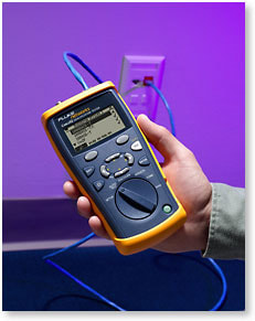
Узнайте, какие скорости поддерживает существующая сеть.
Четырехсекундный автотест CableIQ четко указывает галочкой c какими скоростями и приложениями может работать тестируемый кабель.
Поиск неисправностей в кабелях
Подключитесь к любому кабелю, коммутационной панели или стенному гнезду и просмотрите детальную информацию о кабеле (длина/схема проводки) и одновременно информацию о деталях устройства на дальнем конце (параметры настройки скорости / двойные параметры настройки). Благодаря ряду испытательных функций кабеля и сети, вы сможете изолировать неполадки соединения. Например, если режим обнаружения показывает, что двойные параметры настройки соответствуют, но неполадка при этом сохраняется, проведите автотест, чтобы определить поддерживает ли кабель необходимую пропускную способность. Если соединение не соответствует квалификации, CableIQ обеспечит подробную информацию о природе и местоположении неполадок кабеля, таких как перекрестная связь или большие изменения импеданса. С прибором CableIQ ваши специалисты смогут быстрее решать проблемы по заявкам о неисправностях, вполовину сократив время, требуемое на устранение неисправностей кабеля.
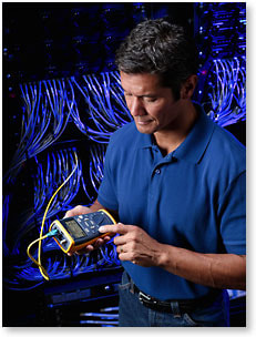
Расследуйте причину неполадок кабельной сети в два раза быстрее.
Этот скрин-шот показывает кабельное соединение, которое не соответствует квалификации 1000BASE-T из-за ошибки связи на 4,1 метра.
Определение инфраструктуры
Освободите 10% или более портов коммутатора
Режим обнаружения CableIQ четко показывает, что находится в дальнем конце любого кабеля. У коммутатора проверьте каждый кабель по одному. Вы сможете быстро увидеть, присутствует ли разрыв кабеля на дальнем конце, или соединен ли он с ПК. Также можно использовать функцию мигания хаба CableIQ с рабочего места, чтобы высветить соответствующий индикатор порта коммутатора. Вы удивитесь, узнав, сколько неиспользованных портов можно освободить и повторно задействовать с использованием CableIQ.
Определите, где проведены установленные кабели, все из одной точки подключения.
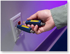
Присоедините удаленные идентификаторы в различных точках подключения, затем выполните многократные испытания кабелей от центра распределения или коммутационного шкафа. CableIQ обеспечивает определение проводки, длину пар, расстояние до неполадки, и удаленное распознание каждого проверяемого кабельного соединения.
Функция составления схемы разводки кабелей Intelligent Wiremap
Интеллектуальная система проводки проводит испытание на длину, замыкания, расщепления пар, или разрывы и показывает местонахождение неполадки при помощи доступного графического интерфейса.
Система Intelligent Wiremap прибора CableIQ четко указывает на разрыв на контакте 6 дальнем конце испытуемого кабеля (130 футов/34 метра).
Технология IntelliTone
Определите местонахождение кабелей и проводов с превосходной точностью
Прибор CableIQ поддерживает генерацию цифровых тональных сигналов IntelliTone посредством приведенных ниже функций.
- Более легкое обнаружение и отслеживание кабелей с большей степенью точности по сравнению с другими приборами, представленными на рынке.
- Настройка и безопасное отслеживание кабеля в живой сети
- Обеспечение двух цифровых тонов и четырех аналоговых тонов
- Включает в себя функции составления схемы разводки кабелей и последующего отслеживания IntelliTone; пользуйтесь детектором IntelliTone Pro 200 для проверки схемы разводки кабелей
Удобство использования
Вооружите техничестких специалистов, работающих напрямую с клиентами, простым в обращении инструментом
Благодаря доступному пользовательскому интерфейсу и графическим изображениям на дисплее, пользователь может следовать инструкциям при минимальном уровне необходимого обучения или без него.
- Поворотный переключатель упрощает обучение и эксплуатацию. Вы всегда знаете, какой тестовый модуль выбран
- Портативная, легкая, прочная эргономичная конструкция для легкого практического использования
- Четыре батарейки типа AA — длительный срок службы в течение нескольких недель тестирования
- Адаптер схемы разводки также выполняет функцию защитной крышки
По словам клиента: «Я вручил CableIQ нашим техникам III-го уровня, они включили устройство и начали испытание в течение двух минут после рассмотрения имеющихся различных вариантов».
—Телекоммуникационный аналитик
Варианты комплекта CableIQ
Чтобы получить максимум от владения CableIQ, выберите один из наших специализированных комплектов. Каждый комплект разработан для тестирования квалификаций при определенных условиях работы. Читайте дальше, чтобы получить подробные сведения о каждом комплекте.
CIQ-KRQ, набор квалификаторов линий в жилых зданиях CableIQ Residential Qualifier Kit
Набор квалификаторов линий в жилых зданиях CableIQ Residential Qualifier Kit разработан для специалистов по установке кабелей в жилых зданиях, которым необходимо документировать, что кабельные системы установлены правильно и надежно работают. Он быстро квалифицирует кабельные сети в жилых зданиях для поддержания голосовой связи, VoIP, 10/100/1000 Ethernet и абонентского телевидения. Благодаря входящим в комплект адаптерам, набор заменяет многочисленные инструменты для тестирования и поиска неисправностей соединений голосовой связи, передачи данных, аудио/видео соединений, коаксиальных систем и соединений систем безопасности. Программное обеспечение, входящее в CableIQ Reporter позволяет установщикам сразу же начать производство отчетов о профессиональных испытаниях.
CIQ-KIT, Расширенный набор CableIQ для ИТ
Расширенный набор CableIQ для ИТ разработан для достижения максимальной эффективности любой задачи по квалификации кабеля. Используйте зонд IntelliTone 200, входящий в набор, для того, чтобы быстро и четко определить нахождение кабелей даже в активных сетях. Используйте шесть входящих в набор идентификаторов кабеля для выполнения большого объема тестов квалификации в короткий период времени. Каждый идентификатор кабеля способен выполнить простой тест разводки или полный квалификационный тест. Возможно выполнение до семи квалификационных тестов без возвращения к коммутационной панели. Для облегчения перемещения инструментов с одного объекта на другой можно воспользоваться прочным защитным кейсом.
CIQ-FTKSFP, комплект Copper and Fiber Technician’s Kit
Комплект Copper and Fiber Technician’s Kit предназначен для ИТ-специалистов, которые работают с медными оптоволоконными сетями. Он предлагает все преимущества комплекта Advanced IT Kit, а также позволяет протестировать оптоволоконные соединения с помощью измерителя мощности Simplfiber Pro и источника света.
В чем заключается квалификация?
Квалификация – это функция новой категории тестеров, используемая сетевыми специалистами при модернизации сети для поддержки более высоких скоростей передачи данных, а также при устранении неисправностей связи. Тестеры квалификации, такие как новый CableIQ Qualification Tester от компании Fluke Networks, определяет, способна ли существующая связь поддержать определенные скорости сети и технологии. Это отличается от сертификационных тестеров, таких, как DTX CableAnalyzer, который гарантирует, что проложенный кабель соответсвует стандартам производительности TIA/ISO и основных тестеров проверки, таких как MicroScannerPro, который проверяет, правильно ли подсоединен кабель.
Тестеры квалификации позволяют техническому персоналу выполнить процедуру поиска неисправностей, чтобы лучше изолировать кабель от проблем в сети. Например, первым шагом в поиске неисправностей при неполадках соединения к сети может быть проверка скорости и настроек параметров дуплекса подсоединенных устройств. Если тестер показывает, что настройки параметров совпадают, но неполадка при этом сохраняется, можно выполнить квалификационное испытание. Выполнение квалификационного испытания позволит технику определить, является ли причиной неполадки недостаточная пропускная способность. Знание пропускной способности кабельного соединения позволит вам быстрее разрешить заявки о неисправности и облегчит модернизацию сети на более высокие скорости.
Выбор нужного инструмента для работы
Когда следует использовать квалификационный тестер: Если вы — сетевой техник и должны убедиться, что существующая кабельная проводка в состоянии поддержать вашу сеть 1000BASE-T, квалификационный тестер является наиболее подходящим устройством. Если вам необходимо расследовать причину неполадки соединения и отделить неполадки кабеля от неполадок сети, квалификация является прекрасным решением. Если вы осуществляете небольшие добавления, перемещения и изменения в уже существующей сети, или настраиваете временную сеть, и вам нужно просто квалифицировать ее для определенной сетевой технологии, самым подходящим устройством является инструмент квалификации.
Когда следует использовать сертификационный тестер: Если вы являетесь промышленным установщиком или владельцем сети, и Вам необходимо доказать, что все кабели установлены правильно и в соответствии с техническими условиями TIA или ISO, вы должны это сертифицировать. Если Вы занимаетесь поиском неисправностей, и должны однозначно показать, что испытуемое соединение не соответствует требованиям к работе категории 5e или 6, согласно стандартам TIA или ISO, вам следует воспользоваться исключительно сертификационным инструментом. Если в вашей сети используются одновременно оптоволоконные и медные кабели, и вам часто приходится тестировать оба вида кабелей, вам помогут приборы для сертификации кабельных систем.
Чтобы получить поддержку и финансовую безопасность гарантии изготовителя, сертификация согласно стандартам TIA/ISO — ваш единственный выбор. В случае применения других методов, ответственным за работу установки становится установщик, что может вылиться в серьезные затраты. Например, крупная 1000 сетевая установка может представлять из себя проект стоимостью в 100 000 долларов США, что является огромной ответственностью, если гарантия изготовителя не получена.
Когда следует использовать инструмент верификации: Инструменты проверки обычно используются любым техником, который протягивает и обрезает кабель или выполняет базовые переносы, добавления и изменения в сети. Эти инструменты используются как первая линия защиты при обнаружении неполадок нахождения связи и скруток пар проводов.
Обнаружив ошибку или неточность в тексте или описании товара, выделите ее и нажмите Shift+Enter.
Комплект поставки
| Главный блок CableIQ с удаленным адаптером — 1 шт. |
| Цифровой детектор IntelliTone 200 Digital Probe — 1 шт. |
| Идентификаторы Remote ID (№2–7) — 1 шт. |
| Коммутационный шнур RJ45-RJ45 — 2 шт. |
| USB-кабель — 1 шт. |
| Коаксиальный вставной адаптер типа F — 1 шт. |
| Коаксиальный коммутационный шнур с сопротивлением 75 Ом — 1 шт. |
| Универсальный разветвитель RJ45/11 — 1 шт. |
| Коммутационный шнур RJ11-RJ11 — 1 шт. |
| Батарейки типа AA — 4 шт. |
| Компакт-диск и краткое руководство пользователя — 1 шт. |
| Компакт-диск с ПО CableIQ Reporter — 1 шт. |
| Мягкая сумка для тестера — 1 шт. |
| Большая сумка — 1 шт. |
Обнаружив ошибку или неточность в тексте или описании товара, выделите ее и нажмите Shift+Enter.
|
Поддерживаемые типы кабелей |
UTP, STP, FTP, SSTP, RG6, RG59, кабели безопасности и кабели для передачи звука |
|
Автотесты квалификации |
1000BASE-T, 100BASE-TX, 10BASE-T, VoIP, 1394b S100, TELCO, только схема разводки кабелей, коаксиальные кабели |
|
Поддерживаемые тесты |
Схема разводки кабелей, длина, производительность сигналов кабеля, цифровые тональные сигналы, аналоговые тональные сигналы, обнаружение и идентификация портов Ethernet, обнаружение аналоговых телефонов, мигание светового индикатора портов, целостность, тест динамиков, обнаружение неисправностей кабеля, обнаружение видеосигнала. |
|
Схема разводки кабелей |
Обнаружение неисправностей одножильного кабеля и поддержка режима MultiMap с количеством удаленных идентификаторов офиса, не превышающим семи. Создание графической схемы пропорционального соотношения длины кабеля и разрывов. Обнаружение расщепленных пар. |
|
Поиск неисправностей |
Измерение перекрестных наводок и сопротивления; их сравнение с соответствующими ограничениями зависимо от выбранного теста. Обнаружение расположения крупных точечных источников, а также распределенных источников в кабельных системах, если эти источники достаточны для того, чтобы системы не прошли квалификацию по применению. |
|
Хранение результатов |
До 250 результатов квалифицирующего тестирования. |
|
Мощность |
Тип батареек: 4 щелочные батарейки типа AA (NEDA 15A, IEC LR6). |
|
Время работы от батарей |
20 ч. использования в обычном режиме, без использования подсветки. |
|
Другие поддерживаемые типы батареек |
4 батарейки типа AA – фото-литиевые, никель-метал-гидридные NiMH, никель-кадмиевые NiCD |
|
Размеры и вес |
7 дюймов x 3,5 дюйма x 1,75 дюйма (17,8 см x 8,9 см x 4,5 см); 1,2 фунта (0,55 кг) |
Обнаружив ошибку или неточность в тексте или описании товара, выделите ее и нажмите Shift+Enter.
Нет отзывов о данном товаре.
Написать отзыв
Обнаружив ошибку или неточность в тексте или описании товара, выделите ее и нажмите Shift+Enter.
User Manual for FLUKE models including: CableIQ Qualification Tester
Other compatible battery types: 4 AA photo lithium, NIMH, NICAD. Serial interface. USB mini-B 5-pin connector. Dimensions and weight.
Qualification Tester — images-na.ssl-images-amazon.com
info@flukenetworks.com 1-425-446-5500 • Australia: 61 (2) 8850-3333 or 61 (3) 9329 0244 • Beijing: 86 (10) 6512-3435 • Brazil: 11 3759 7600 • Canada: 1-800-363-5853 • Europe: 31-(0) 40 2675 600 • Hong Kong: 852 2721-3228 • Japan: 03-6714-3117 • Korea: 82 2 539-6311 • Singapore: 65-6799-5566 • Taiwan: (886) 2-227-83199
- PDF Viewer
- Universal Document Viewer
- Google Docs View
- Google Drive View
- Download Document [pdf]
- Download Document [Optimized]
- Document:
- Text
- References
Not Your Device? Search For Manuals / Datasheets:
File Info : application/pdf, 92 Pages, 952.52KB
Document91Dk83YMKPL
January 2005, Rev. 6 6/2018
© 2005, 2007, 2009, 2015-2018 Fluke Corporation All product names are trademarks of their respective companies.

CableIQ TM Qualification Tester Users Manual

LIMITEDWARRANTYANDLIMITATIONOFLIABILITY
Each Fluke Networks product is warranted to be free from defects in material and workmanship under normal use and service unless stated otherwise herein. The warranty period for the mainframe is one year and begins on the date of purchase. The CableIQ remote unit is also warranted for one year. Parts, accessories, product repairs and services are warranted for 90 days, unless otherwise stated.Ni-Cad, Ni-MH and Li-Ion batteries, cables or other peripherals are all considered parts or accessories. The warranty extends only to the original buyer or end user customer of a Fluke Networks authorized reseller, and does not apply to any product which, in Fluke Networks' opinion, has been misused, abused, altered, neglected, contaminated, or damaged by accident or abnormal conditions of operation or handling. Fluke Networks warrants that software will operate substantially in accordance with its functional specifications for 90 days and that it has been properly recorded on non-defective media. Fluke Networks does not warrant that software will be error free or operate without interruption. Fluke Networks authorized resellers shall extend this warranty on new and unused products to end-user customers only but have no authority to extend a greater or different warranty on behalf of Fluke Networks. Warranty support is available only if product is purchased through a Fluke Networks authorized sales outlet or Buyer has paid the applicable international price. To the extent permitted by law, Fluke Networks reserves the right to invoice Buyer for repair/replacement when a product purchased in one country is submitted for repair in another country. For a list of authorized resellers, visit www.flukenetworks.com/wheretobuy. Fluke Networks warranty obligation is limited, at Fluke Networks option, to refund of the purchase price, free of charge repair, or replacement of a defective product which is returned to a Fluke Networks authorized service center within the warranty period. To obtain warranty service, contact your nearest Fluke Networks authorized service center to obtain return authorization information, then send the product to that service center, with a description of the difficulty, postage and insurance prepaid (FOB destination). Fluke Networks assumes no risk for damage in transit. Following warranty repair, the product will be returned to Buyer, transportation prepaid (FOB destination). If Fluke Networks determines that failure was caused by neglect, misuse, contamination, alteration, accident or abnormal condition of operation or handling, or normal wear and tear of mechanical components, Fluke Networks will provide an estimate of repair costs and obtain authorization before commencing the work. Following repair, the product will be returned to the Buyer transportation prepaid and the Buyer will be billed for the repair and return transportation charges (FOB Shipping point). THIS WARRANTY IS BUYER'S SOLE AND EXCLUSIVE REMEDY AND IS IN LIEU OF ALL OTHER WARRANTIES, EXPRESS OR IMPLIED, INCLUDING BUT NOT LIMITED TO ANY IMPLIED WARRANTY OF MERCHANTABILITY OR FITNESS FOR A PARTICULAR PURPOSE. FLUKE NETWORKS SHALL NOT BE LIABLE FOR ANY SPECIAL, INDIRECT, INCIDENTAL OR CONSEQUENTIAL DAMAGES OR LOSSES, INCLUDING LOSS OF DATA, ARISING FROM ANY CAUSE OR THEORY. Since some countries or states do not allow limitation of the term of an implied warranty, or exclusion or limitation of incidental or consequential damages, the limitations and exclusions of this warranty may not apply to every buyer. If any provision of this Warranty is held invalid or unenforceable by a court or other decision-maker of competent jurisdiction, such holding will not affect the validity or enforceability of any other provision. 4/15-CIQ
Fluke Networks PO Box 777 Everett, WA 98206-0777 USA

TableofContents

Title

Page

Overview of Features .................................................................................................... 1 Registration ................................................................................................................... 2 Contacting Fluke Networks .......................................................................................... 2 Additional Resources for Cable Testing Information .................................................. 3 Unpacking ..................................................................................................................... 3
CableIQ Advanced IT Kit (CIQ-KIT) .......................................................................... 3 CableIQ Qualification Tester (CIQ-100) ................................................................... 4 CableIQ Copper and Fiber Technician's Kit (CIQ-FTKSFP)....................................... 4
WSymbols and Safety Information ............................................................................. 5
Physical Features ........................................................................................................... 8 Using the Wiremap Adapter and Remote ID Locators................................................ 10 Powering the Tester...................................................................................................... 11 Verifying Operation ...................................................................................................... 11

i

CableIQQualificationTester
UsersManual
SettingUserPreferences.............................................................................................. 11 ChangingtheLanguageandLengthUnits............................................................ 11 SettingtheTimeandDate...................................................................................... 12 EnteringUserInformation...................................................................................... 12 AutoShutoff............................................................................................................ 14 EnablingorDisablingtheSpeaker......................................................................... 14 ResettingtoFactorySettings.................................................................................. 14
CheckingtheHardwareandSoftwareVersions......................................................... 15 QualifyingCablingwiththeAutotest......................................................................... 15
SelectingTeststoRun.............................................................................................. 18 AutotestonTwistedPairCabling........................................................................... 19
ConnectingtoStarTopologies........................................................................... 20 ConnectingtoBusTopologies............................................................................ 22 AboutQualificationforVoIP(VoiceOverInternetProtocol)........................... 22 AutotestResultsforTwistedPairCabling.............................................................. 24 WiremapResults................................................................................................. 25 SignalPerformanceResults................................................................................ 28 LengthResults..................................................................................................... 30 AutotestonCoaxialCabling(75)........................................................................ 32 DiscoveringCablingCharacteristics............................................................................. 37 DiscoverModeResultsforTwistedPairCabling.................................................... 38 DiscoverModeResultsforCoaxialCabling............................................................ 42 TDRPlotforCoaxialCabling................................................................................... 44 UsingMultipleRemoteIDLocatorsinDiscoverMode(MultiMapTM).................... 46 UsingtheToner............................................................................................................ 48
ii

Contents (continued)
UsingtheIntelliToneCableMapFunction.................................................................. 50 BlinkingaPortLight..................................................................................................... 51 TestingforContinuity................................................................................................... 52 UsingtheContinuityToner.......................................................................................... 54 LocatingCrosstalkandImpedanceFaultsonTwistedPairCabling........................... 56 TestingSpeakerCabling............................................................................................... 58 CalibratingLengthMeasurements............................................................................... 60
SettingtheNVPtoaSpecifiedValue...................................................................... 60 DeterminingaCable'sActualNVP.......................................................................... 61 MemoryFunctions........................................................................................................ 62 ViewingSavedResults............................................................................................. 62 DeletingResults........................................................................................................ 62 UploadingResultstoaPC........................................................................................ 62 Maintenance................................................................................................................. 63 UpdatingtheTester'sSoftware............................................................................... 63 ReplacingtheBatteries............................................................................................ 64 Cleaning.................................................................................................................... 65 IfSomethingSeemsWrong.......................................................................................... 65 OptionsandAccessories............................................................................................... 67 Specifications................................................................................................................. 68 EnvironmentalSpecifications.................................................................................. 68 GeneralSpecifications.............................................................................................. 69 PerformanceSpecifications...................................................................................... 70 RegulatoryInformation........................................................................................... 71 AppendixA:DiagnosingCablingFaults...................................................................... 73 Index.............................................................................................................................. 79
iii

CableIQQualificationTester
UsersManual
iv

ListofFigures

Figure

Title

Page

1. ExamplesofVoltageAlertScreens ..................................................................................... 7 2. Features ................................................................................................................................ 8 3. UsingtheUniversalAdapterforConfinedAreas ............................................................... 10 4. EditingText .......................................................................................................................... 13 5. AutotestSetupScreens ........................................................................................................ 18 6. AutotestConnectionsforTwistedPairNetworkCabling .................................................. 20 7. AutotestConnectionsforTelephoneCablinginaStarTopology..................................... 21 8. AutotestConnectionsforTelephoneCablinginaBusTopology ..................................... 23 9. AutotestSummaryScreens .................................................................................................. 24 10. TypicalWiremapScreens ..................................................................................................... 25 11. SignalPerformanceResults ................................................................................................. 28 12. LengthResultScreens .......................................................................................................... 30 13. AutotestConnectionsforCoaxialCabling(cablingwithsplittershown) ......................... 33 14. AutotestResultsforCoaxialCabling................................................................................... 34 15. DiscoverModeResultsforTwistedPairCabling ................................................................ 38 16. DiscoverModeResultsforCoaxialCabling ........................................................................ 42 17. TDRPlotsforCoaxialCabling.............................................................................................. 44

v

CableIQQualificationTester
UsersManual 18. MultiMapResults.................................................................................................................  46 19. UsingMultipleRemoteIDLocators ....................................................................................  47 20. UsingtheToner(twistedpairexample) .............................................................................  49 21. UsingtheTonerwiththeIP200IntelliToneCableMapFunction .....................................  50 22. BlinkingaPortLight............................................................................................................  51 23. TestingforContinuity .........................................................................................................  53 24. UsingtheContinuityTonertoTestSecuritySwitches .......................................................  55 25. TestingSpeakerCabling......................................................................................................  59 26. ReplacingtheBatteries .......................................................................................................  65
vi

ListofTables

Table

Title

Page

1. InternationalElectricalSymbols .......................................................................................... 5 2. AutotestParameters ............................................................................................................ 17 3. CrosstalkandImpedanceFaultMessages........................................................................... 57 4. TroubleshootingtheTester ................................................................................................. 66 5. OptionsandAccessories ...................................................................................................... 67

vii

CableIQQualificationTester
UsersManual
viii

CableIQQualificationTester

OverviewofFeatures
TheCableIQTMQualificationTesterisahand-heldtester thatletsyoutestwiringandqualifythetransmission capabilitiesoftwistedpairand75coaxialcabling installations.
Thetesteroffersthefollowingfeatures:
· AutotestfunctionqualifiescablingforEthernet, telephone,orCATVserviceinlessthan4seconds.
· Identifieswiremapfaults,bridgetaps,andport characteristics.
· Discovermodeautomaticallyreportscable characteristicsandtellsyouifthecableisconnected toadevice.
· DetectsanddisplaysthestrengthofRFcoaxial televisionsignals.

· MultiMapTMfunctiontestsmultiplesegmentsthrough bridgetapsanddetectsfaultsonindividual conductors.
· DetectsEthernetserviceontwistedpaircablingand televisionserviceoncoaxialcabling.
· Locatescrosstalkfaultsontwistedpaircablingand impedancefaultsontwistedpairandcoaxialcabling.
· IntelliToneTMfunctionworkswithFlukeNetworks ITK100orITK200probestohelpyoulocateand isolatecablesbehindwalls,atpatchpanels,orin bundles.Tonerfunctionalsoworkswithstandard analogprobes.
· Continuitytonersimplifiestestingofsecurity switchesatdoorsandwindows.
· Blinkstheportlightonahuborswitchtohelpyou verifyconnectivityandcablerouting.
· Speakertestletsyouquicklyverifyspeaker connections.
1

CableIQQualificationTester UsersManual
· Saves up to 250 Autotest results in internal memory. · Runs for 20 to 30 hours during typical use. Powered
by 4 AA alkaline batteries. · Multi-language display supports English, French,
German, Italian, Portuguese, Spanish, and Japanese (katakana). · CableIQ Reporter software lets you upload test results to a PC and create professional-quality test reports.
Registration
Registering your product with Fluke Networks gives you access to valuable information on product updates, troubleshooting tips, and other support services. To register, fill out the online registration form on the Fluke Networks website at www.flukenetworks.com/registration.
2

ContactingFlukeNetworks
Note
IfyoucontactFlukeNetworksaboutyourtester, havethetester'ssoftwareandhardwareversion numbersavailableifpossible.
www.flukenetworks.com
info@flukenetworks.com +1-425-446-5500
· Australia: 61 (2) 8850-3333 or 61 (3) 9329 0244 · Beijing: 86 (10) 6512-3435 · Brazil: 11 3759 7600 · Canada: 1-800-363-5853 · Europe: +31-(0) 40 2675 600 · Hong Kong: 852 2721-3228 · Japan: 03-6714-3117 · Korea: 82 2 539-6311 · Singapore: 65-6799-5566 · Taiwan: (886) 2-227-83199 · USA: 1-800-283-5853 · Anywhere in the world: +1-425-446-5500
Visit our website for a complete list of phone numbers.

Additional Resources for Cable Testing Information

AdditionalResourcesforCableTesting Information
The Fluke Networks Knowledge Base answers common questions about Fluke Networks products and provides articles on cable testing techniques and technology. To access the Knowledge Base, log on to www.flukenetworks.com, then click SUPPORT > KnowledgeBase at the top of the page.
Unpacking
The tester comes with the accessories listed below. If something is damaged or missing, contact the place of purchase immediately.
For the latest list of options and accessories visit the Fluke Networks website at www.flukenetworks.com.
Note
CableIQReportersoftwareisavailableonthe FlukeNetworkswebsite

CableIQAdvancedITKit(CIQ-KIT)
· CableIQ Qualification Tester with detachable wire map adapter
· Four AA alkaline batteries · IP200 IntelliTone tone probe · 9 V battery · Six remote ID adapters, ID numbers 2 through 7 · Two patch cords, 8-pin modular plug to 8-pin
modular plug (RJ45 to RJ45), 2 m · Patch cord, 6-pin modular plug to 6-pin modular
plug (RJ11 to RJ11), 15.2 cm · Coaxial patch cord, F-connector to F-connector, 75 ,
1.5 m · Universal adapter, 8-pin/4-pin modular jack to
8-pin/4-pin modular jack · F-connector barrel adapter · USB cable for PC communications · Folding pouch for accessories · Hard carrying case · Getting Started Guide · CD-ROM with CableIQ Reporter software and
product manuals

3

CableIQQualificationTester UsersManual
CableIQQualificationTester(CIQ-100)
· CableIQ Qualification Tester with detachable wire map adapter
· Four AA alkaline batteries · Two patch cords, 8-pin modular plug to 8-pin
modular plug (RJ45 to RJ45), 2 m · F-connector barrel adapter · USB cable for PC communications · Carrying case · Getting Started Guide · CD-ROM with CableIQ Reporter software and
product manuals

CableIQCopperandFiberTechnician's Kit(CIQ-FTKSFP)
· CableIQ Advanced IT Kit (CIQ-KIT) · SimpliFiber Pro Fiber Test Kit (FTK 1000):
o SimpliFiber Pro optical power meter o SimpliFiber Pro 850/1300 source o Four AA alkaline batteries o USB cable for PC communications o Carrying case o Getting Started Guide

4

WSymbolsandSafetyInformation
Table 1 describes the international electrical symbols used on the tester and in this manual.

Table1.InternationalElectricalSymbols

W Warning or Caution: Risk of damage or destruction to equipment or software. See explanations in the manual.

X Warning: Risk of electric shock.

 j
~

Consult the user documentation
This equipment not for connection to public communications networks, such as active telephone systems.
This product complies with the WEEE Directive marking requirements. The affixed label indicates that you must not discard this electrical/electronic product in domestic household waste. Product Category: With reference to the equipment types in the WEEE Directive Annex I, this product is classed as category 9 "Monitoring and Control Instrumentation" product. Do not dispose of this product as unsorted municipal waste. To return unwanted products, contact the manufacturer's web site shown on the product or your local sales office or distributor.

WSymbolsandSafety Information


40 year Environment Friendly Use Period (EFUP) under China Regulation - Administrative Measure on the Control of Pollution Caused by Electronic Information Products. This is the period of time before any of the identified hazardous substances are likely to leak out, causing possible harm to health and the environment.
Conforms to relevant Australian standards.


MSIP-REM-FLK-016005052: EMC approval for Korea

Class A Equipment (Industrial Broadcasting & Communication Equipment)
This product meets requirements for industrial (Class A) electromagnetic wave equipment and the seller or user should take notice of it. This equipment is intended for use in business environments and is not to be used in homes.

Warning
Toavoidpossiblefire,electricshock,or personalinjury:

· Do not open the case; no user-serviceable partsareinside.

· Donotmodifythetester.

· Do not use the tester if it is damaged. Inspectthetesterbeforeuse.

5

CableIQQualificationTester UsersManual
· Ifthisequipmentisusedinamannernot specifiedbythemanufacturer,the protectionprovidedbytheequipment maybeimpaired.
· Thetesterisnotintendedtobeconnectedto activetelephoneinputs,systems,or equipment,includingISDNdevices.Exposure tothevoltagesappliedbytheseinterfaces maydamagethetesterandcreateapotential shockhazardfortheuser.
· Ifthetesterdetectsvoltage,itshowsa screenthatincludesthevoltagealert
symbol().Figure1showsexamplesof
thesescreens.Disconnectthetesterifthe voltagealertsymbolappears.
· Alwaysturnonthetesterbeforeconnecting it to a cable. Turning the tester on activates thetool'sinputprotectioncircuitry.
· Donotusethetesterifitoperates abnormally.Protectionmaybeimpaired.
· Readthesafetyinformationgiveninthe SafetyInformationbookletbeforeusing thetester.
6

Caution
Toavoiddatalossandtoensure maximumaccuracyoftestresults:
· NeverattempttosenddatafromaPCto thetesterwhilerunningacabletest.
· Neveroperateportabletransmittingdevices, suchaswalkie-talkiesandcellphones,during acabletest.
· Replacethebatteriesassoonasthelow batterymessageappears.

SafetyInformation

avv62.bmp
Telephonevoltagesdetected.

avv57.bmp
PoweroverEthernet voltagesdetected.

avv58.bmp
ISDNvoltagesdetected (NT-1interface)

WXRefertothewarnings
onpage6.

avv59.bmp
Voltagefromanunknown devicedetected.

avv61.bmp
Voltagedetectedacrosswiresfrom differentpairs(forexample,across1 and7).

Note
Thetestermaynotcorrectlyidentify devicesthatusenon-standard wiring.

Figure1.ExamplesofVoltageAlertScreens

7

CableIQQualificationTester UsersManual
PhysicalFeatures

Figure2.Features

avv01f.eps

8


PhysicalFeatures

A LCDdisplaywithbacklight.

I G:Togglesthebacklightbetweendimandbright

B J K:Thesoftkeysprovidefunctionsrelatedto

settings.

thecurrentscreen.Thecurrentfunctionsareshownon J I:Exitsthecurrentscreen.Alsoexiteditmodewhen

thescreenabovethekeys.

makingselectionsandeditingtext.

C P:Startsthecurrentlyselectedtest.

K F-connectorforconnectingto75coaxialcable.

D H:Enterkeyselectsthehighlighteditemfroma
menu.Entersandexitseditmodewhenmaking selectionsandeditingtext.

L Modularjackforconnectingtotelephoneandtwisted
pairnetworkcable.Thejackaccepts8-pinmodular (RJ45)and6-pinmodular(RJ11)connectors.

E Rotaryswitchselectsthetester'smodes.
F USBportforuploadingtestreportstoaPCand
updatingthetester'ssoftware.See"UploadingResults toaPC"onpage62.
G L:On/offkey.
H B C A D:Arrowkeysfornavigatingthrough
screensandincrementingordecrementing
alphanumericvalues.Fornavigation,useB Ctopage upanddown.UseSHIFTandAorDtogotothe
toporbottomofalist.

M WiremapadapterwithF-connectorandmodularjack.
See"UsingtheWiremapAdapterandRemoteID Locators"onpage10fordetails.
N RemoteIDlocator(optional)withF-connectorand
modularjack.See"UsingtheWiremapAdapterand RemoteIDLocators"onpage10fordetails.

Figure2.Features(cont.)

9

CableIQQualificationTester UsersManual
UsingtheWiremapAdapterand RemoteIDLocators
Terminatingthecablingundertestwiththestandard wiremapadapteroroptionalremoteIDlocatorsprovides thefollowingadvantages:
· Fullwiremaptestingontwistedpaircabling
WithoutanadapterorIDlocator,thecablingcannot bequalifiedbecausethetestercannotdetectall wiremapfaults.Autotestresultsareprovidedfor informationalpurposesonly.
· Easieridentificationoftwistedpairandcoaxial connections
Theadapter'snumberappearsonthewiremap display.InDiscovermodeyoucanusemultiple remoteIDlocators,eachwithadifferentnumber,to identifyconnectionsatpatchpanels.

ThewiremapadapterandremoteIDlocatorsare functionallyidentical,exceptfortheirIDnumbers.The wiremapadapterhasanIDnumberof1.TheremoteID locatorsareavailablewithotherIDnumbers.
ToconnecttheremoteIDlocatortoamodular(RJ)outlet inaconfinedarea,usetheoptionaluniversaladapterand apatchcord.SeeFigure3.

avv54f.eps
Figure3.UsingtheUniversalAdapterfor ConfinedAreas
10


PoweringtheTester
YoucanpowerthetesterwithfourAAalkalinebatteries (included),fourrechargeablenickel-metalhydrideor nickel-cadmiumbatteries,orfour1.5Vlithiumbatteries.
Mostofthetester'sscreensshowabatterystatusicon (b)neartheupper-leftcorner.ThemessageLow Batteries!appearswhenthebatteriesaretoolowforthe testertofunction.
Thebatterieslastabout20hoursduringtypicaluse(with thebacklightatthedimsetting).
Figure26onpage65showshowtoreplacethebatteries.
VerifyingOperation
Thetesterperformsabasicself-testwhenyouturniton.If thetesterreportsanerrorordoesnotturnon,referto"If SomethingSeemsWrong"onpage65.

 PoweringtheTester
SettingUserPreferences
Thefollowingsectionsdescribesettingsyoumaywantto changewhenyoufirststartusingthetester.ForAutotest settings,see"SelectingTeststoRun"onpage18.
ChangingtheLanguageandLengthUnits
Tochangethelanguageandlengthunits:
1 TurntherotaryswitchtoSETUP.
2 PressDtohighlightLanguage/mft;thenpress HorJ.
3 UseADtohighlightasetting;thenpressHor
J.
4 UseADtochangethesetting;thenpressH.


11

CableIQQualificationTester UsersManual
SettingtheTimeandDate
ThetimeanddatearestoredwithsavedAutotests.The timesettingusesa24-hourclock. Tosetthetimeanddate: 1 TurntherotaryswitchtoSETUP.
2 PressDtohighlightTime/Date;thenpressHor
J.
3 Toselectafieldtoedit,useBCtohighlightthe field;thenpressHorJ.
4 UseADtochangethesettingintheselected field;thenpressH.
12

EnteringUserInformation
TheUserInformationscreenletsyouenterthreelinesof textthatarestoredwithsavedAutotestresults.For example,youcouldentertheoperator'snameandyour company'snameandlocation.
Toenteruserinformation:
1 TurntherotaryswitchtoSETUP.
2 UseDtohighlightUserInformation;thenpressH
orJ.
3 UseADtohighlightaboxtoedit;thenpressH
orJ.
4 UseB CADandthesoftkeystoeditthetext,as
describedinFigure4.
5 PressHtosavechangesintheselectedbox.
6 Repeatsteps3through5toedittextinotherboxes.


SettingUserPreferences

A Thethreefieldsfortextentry.

B Indicatesthefieldisselectedforediting.Toselectafield,
useADtohighlightthefield;thenpressHorJ.

BC:Movesthecursor.Movingthecursorbeyondthe
lastcharacterinsertsthefirstcharacterfromthelast
character'sset.

avv11f.eps
CharacterSetsAvailable ABCDEFGHIJKLMNOPQRSTUVWXYZ abcdefghijklmnopqrstuvwxyz 0123456789 # " ! $ % & ' (  ) * + , - . / : ; < = > ? @ [  \  ] ^ _  ` {  |  }  space

AD:Changesthehighlightedcharacter.
JIns:Insertsthefirstcharacterfromthesetthat
includesthehighlightedcharacter.
KDel:Deletesthehighlightedcharacter.
SHIFTandDorSHIFTandA:Changesthecharacter
set.
Tosavechangestoafield,pressH.

C Indicatesthetextextendsbeyondthebox.UseBCto
scroll.

Figure4.EditingText

13

CableIQQualificationTester UsersManual
AutoShutoff
Youcansetthetestertostayonindefinitelyorturnoff after15minutesofinactivity.
Tosettheautoshutoff:
1 TurntherotaryswitchtoSETUP.
2 PressDtohighlightAutoShutoff;thenpressHor
J.
3 PressHorJ,useADtoselect15Minor Never;thenpressH.
EnablingorDisablingtheSpeaker
Turningoffthespeakerdoesnotdisablesoundsforthe continuityandtonerfunctions.
Toturnthespeakeronoroff:
1 TurntherotaryswitchtoSETUP.
2 PressDtohighlightSpeaker;thenpressHor
J.
3 PressHorJ,useADtoselectOnorOff; thenpressH.

ResettingtoFactorySettings
TheFactorySettingsfunctionresetsthefollowingto factorysettings: · NVPsettings · TestsselectedfortheAutotest · WiremappairselectionsforAutotests Toresettofactorysettings: 1 TurntherotaryswitchtoSETUP.
2 PressDtohighlightFactorySettings;thenpress HorJ.
3 PressJYes.

14


CheckingtheHardwareandSoftware Versions
Youmayneedtocheckyourtester'shardwareor softwareversionsbeforeupdatingthesoftwareorifyou contactFlukeNetworksaboutthetester. 1 TurntherotaryswitchtoSETUP.
2 PressDtohighlightVersionInformation;then pressHorJ.
TheVersionscreenshowsthefollowing: · SN:Serialnumber · SW:Softwareversion · HW:Hardwareversion · HWDate:Thedatethetester'soperationwas
lastverifiedataFlukeNetworksservicecenter.

 CheckingtheHardwareandSoftwareVersions
QualifyingCablingwiththeAutotest
TheAutotesttellsyouifcablingwillsupportaselected application.Ifthecablingdoesnotqualifyforthe application,theAutotest'sfaultinformationhelpsyou diagnosetheproblem.
YoucansaveAutotestresultstodocumentthe installation.
TheAutotestcanqualifycablingforthefollowing applications:
· 10BASE-T,100BASE-TX,and1000BASE-Ttwistedpair Ethernetservice
· VoIP(voiceoverinternetprotocol)
· Firewire(1394b-S100)serviceovertwistedpair cabling
· Analogtelephoneservice
· Wiremapforanyapplication
· 75coaxialapplications,suchascabletelevision

15

CableIQQualificationTester UsersManual
Qualificationdiffersfromthecertificationdonebytesters suchastheFlukeNetworksDTXCableAnalyzer. Certificationinvolvestestingagainstanindustrystandard andatestlimit(Category6andTIACat6PermanentLink, forexample).Thecablingmustperformwithinlimitsfrom 1MHztothehighestfrequencydefinedbystandard.
Qualificationmeansthecablingwillsupportaselected application,suchas100BASE-TXEthernetservice.The Autotestqualifiescablingbytestingtheparameters

showninTable2andcomparingtheresultstothe selectedapplication'srequirements.
IftheAutotestfails,theresultswillhelpyoudiagnosethe problem.Seealso"DiagnosingCablingFaults"onpage73 forcommoncausesoffailures.


16


QualifyingCablingwiththeAutotest

Table2.AutotestParameters

Test

Wiremap1 Length DelaySkew

SignalPerformance2

1000BASE-T

·

·

·

·

100BASE-TX

·

·


·

10BASE-Tovertwistedpair

·

·


·

VoIP

·

·


·

Wiremap

·

·3


1394bS100(Firewire)

·

·


·

Telco

·

·3


Coax(75)

·4

·3


1. WiremapadapterorremoteIDlocatorrequiredforcompletewiremaptesting. 2. Crosstalk,insertionloss(attenuation),andreturnlossaretested.For1000BASE-T,ELFEXT(equal-levelfar-endcrosstalk)isalsotested. 3. Thetesthasnolengthlimit,sothelengthtestalwayspasses. 4. Wiremapforcoaxialcableisshieldandconductorcontinuity.

17

CableIQQualificationTester UsersManual
SelectingTeststoRun
ToselectteststorunduringanAutotest:
TurntherotaryswitchtoSETUP;thenselectAutotests.Or turntherotaryswitchtoAUTOTEST;thenpress
JSetup.

Figure5describeshowtousetheAutotestsetupscreens.


A Thetestsavailable.Toselect(s)ordeselect(n)atest,use
D Atohighlightthetest;thenpressHorJ.
B Thepairsrequired(q)andoptional(s n)fortwistedpairtests.
C Toselectordeselectpairsforthehighlightedtest,pressK
Pairs.
D Toselectordeselectanoptionalpair,useBCtohighlightthe
pair;thenpressHorJ.
PressItosaveyoursettings.


 avv40f.eps
Figure5.AutotestSetupScreens
18


AutotestonTwistedPairCabling
Notes
AwiremapadapterorremoteIDlocatormustbe connectedtotheendofthecablingforthe wiremaptobecompletelyverified.
TheAutotestdoesnotsupportuseofmultiple remoteIDlocators(theMultiMapfunction).
Ifyouusepatchcordsatthenearorfarend duringanAutotest,FlukeNetworksrecommends patchcordsatleast2mlong.
TheAutotestwillnotrunifthetesteris connectedtoadataport,ordetectsvoltageora shortonthecabling.
1 Turnonthetester.Turntherotaryswitchto AUTOTEST.
2 Tochangetheteststorun,JorH.Seepage18.
3 ConnectthetesterandwiremapadapterorIDlocator tothecabling.Figures6,7,and8showtypical connections.
4 PressP.TheAutotestproceedswhenawiremap
adapterorIDlocatorisdetected.Theanalogtoner turnsonifneitherisdetected.

 QualifyingCablingwiththeAutotest
5 Tosavethetest:
a. PressKS.
b. UseADandHtoselecttheSite,Location,
orOutletfieldforediting.Youcanenterupto 17charactersineachfield.SeeFigure4onpage 13fordetailsoneditingtext. Toseealistofpredefinedlabelsforthe
highlightedfield,pressJList.UseAD, B C,orSHIFT+ADtomovethroughthe list.UseHorJtoselectanentry.
c. OntheEnterIDscreen,pressKStosave
theresultswiththeSite,Location,andOutlet entriesshown.
Note ThelastcharacteroftheOutletstringincrements eachtimeyousaveanAutotest.
19

CableIQQualificationTester UsersManual
avv10f.eps
Figure6.AutotestConnectionsforTwistedPair NetworkCabling
20

ConnectingtoStarTopologies
Telephonecableswiredinastartopology(Figure7)are connectedtogetheratabridgetapatthedistribution center.Thebridgetapconnectseachwiretoallother wiresofthesamenumber.
Thetesterdetectsbridgetapsandmeasuresthedistance tothebridgetap.Tomeasurethelengthofeachcable connectedtothebridgetap,youmustconnectthe wiremapadapterorremoteIDlocatortothebridgetap andthetestertothewalloutlet.Thetestercannot measurelengthpastthebridgetapbecausereflections fromthebridgetapconnectionsinterferewith measurements.
Ifyouconnectthetestertothebridgetap,thetester measuresthelengthonlytothebridgetap,whichisonly thepatchcordlength.


QualifyingCablingwiththeAutotest

Figure7.AutotestConnectionsforTelephoneCablinginaStarTopology

avv12f.eps
21

CableIQQualificationTester UsersManual
ConnectingtoBusTopologies
Telephonecableswiredinabustopology(Figure8) connectthewalloutletsinseries.Inthistopology,you measurethelengthfromthelastoutlettothe distributioncenter.
Ifyouconnecttoanoutletinthemiddleoftheseries,the testerreportsabridgetap.Thelengthreportedisthe lengthtotheoutlet,whichisthepatchcordlength.The testercannotmeasurelengthpasttheoutletbecause reflectionsfromthecablesoneithersideinterferewith measurements.
Tip:Toquicklyverifythewiremapsoftelephonecabling connectedtoabridgetap,usetheMultiMap functioninDISCOVERmode.Seepage46.

Ifyouareunsurewhichoutletisthelastinthebus,dothe following:
1 ConnectthewiremapadapterorIDlocatortothe beginningofthebusatthedistributioncenter.
2 Connectthetestertoanoutlet.Turntherotary switchtoDISCOVER.
3 Ifthetesterreportsabridgetap,movetoanother outlet.Thelastoutletwillnotshowabridgetap,and willshowthelengthtothedistributioncenter.
AboutQualificationforVoIP(VoiceOverInternet Protocol)
CablingthatqualifiesforVoIPwillsupportthevoiceover IPapplication;however,thequalityofservicemayvary dependingonotherfactors.Thesefactorsincludethe qualityofthetransmissionsystembetweenthefar-end VoIPdeviceandyourcabling,theequipmentused,and theequipment'sQoS(qualityofservice)settingsand performance.


22


QualifyingCablingwiththeAutotest

Figure8.AutotestConnectionsforTelephoneCablinginaBusTopology

avv13f.eps
23

CableIQQualificationTester UsersManual

AutotestResultsforTwistedPairCabling


TheAutotestshowsresultsinthreelevelsofdetail,as


describedinFigures9through12.

A OverallresultfortheAutotest.

B OverallresultforeachAutotesttype:

F:Thecablingqualifiesfortheapplication.Ifafar-endadapteris notconnected,thetesterassignsairesultbecausethewiremap
cannotbecompletelyverified.

f:Thecablingdoesnotqualifyfortheapplication.

i:Resultsareforinformationalpurposesonly,notforqualification.
Thecablingcannotbecompletelyqualifiedfortheapplication becausethewiremapresultsareincomplete(wiremapadapternot used).

UseADtoscrollthroughthetests.

C PressJMorHtoseesummaryresultsforthehighlighted test.Toseedetailsforatestparameter,useAD BCto highlighttheparameter;thenpressJ MorH.

D PressKStosavetheresults.
avv15f.eps

Figure9.AutotestSummaryScreens


24


WiremapResults

 QualifyingCablingwiththeAutotest

avv16f.eps

(a)

avv17.bmp

(b)

avv18.bmp

A Adaptertypeandnumber(wiremapadapter Openonpin3with(a)andwithout(b)afar-endadapter.Theopenis

asshown,orremoteIDlocator).

beforethemiddleofthecabling.

B Overallresultforthewiremap(passF,failf, Withanadapter,thetesteridentifieswhichwireinthepairisopen.

informational?).SeeFigure9.

Withoutanadapter,onlythepairwiththeopenisidentified.

C Wiremap.Thisexampleshowsagood

Thewiremapdiagramsareproportionaltothecablingtested.For

wiremapwithawiremapadapterconnected. example,ifawireisopenhalfwaydownthecable,theopenappears

inthemiddleofthewiremapdiagram.

Figure10.TypicalWiremapScreens

-continued-

25

CableIQQualificationTester UsersManual

Crossedwires. Detectionrequiresafar-endadapter.

  avv20.bmp

avv19.eps

Splitpair.Continuityfromendtoendiscorrect,butismadewiththe

wrongwires.

Note

Cableswithuntwistedpairs,suchastelephonecords, typicallyshowsplitpairsduetoexcessivecrosstalk.Because thiscrosstalkdoesnotaffectvoicesignals,thesplitpair warningdoesnotcauseaTelcowiremaptesttofail.

Note
Ifthetesterdetectsmultiplefaultsthatproducethewarningsymbol(W),onlythehighest-
priorityfaultisdisplayed.Thepriorityforthesefaults(highesttolowest)issplitpair,bridgetap, andA/Bcrossovercable.
Figure10.TypicalWiremapScreens(cont.)

-continued-


26


QualifyingCablingwiththeAutotest

avv22.bmp
Crossedpairs.Inthiscase,pairs1,2 and3,6arecrossed.Thisislikely causedbymixing568Aand568B cables.
Detectionofcrossedpairsrequiresa far-endadapter.

avv03.bmp
Telephonecablewithpairs3,6and 4,5crossed.Thiscrossoverisnormal fortheflatcordsusedtoconnect telephonestowalloutlets.

avv32.bmp
Bridgetapdetected.
BridgetapsareallowedfortheTelco test,butcauseafailurefornetwork tests.

Figure10.TypicalWiremapScreens(cont.)


27

CableIQQualificationTester UsersManual

SignalPerformanceResults

B Informationaboutthesignalperformance:

· Qualifiedfor<applicationname>:Thecablingwillsupportthe application.

· NoSignalPerformancetestsneededforqualification:Appears fortheTelcoandWiremaponlytests.

avv23f.eps
Note
Signalperformanceresultsforcables lessthan13ft(4m)longmaybe unreliable.
A Qualified/unqualifiedresultforthesignal
performance.Signalperformanceincludes crosstalk,insertionloss,andreturnloss.For 1000BASE-T,ELFEXT(equal-levelfar-end crosstalk)isalsotested.

· Wiringfault!Nottested.:Thetesterdoesnotevaluatesignal performanceifthereisawiremap,length,ordelayskewfault.
· Connectionfault:Alocalizedcrosstalkfaultwasdetected. Localizedfaultsareusuallycausedbybadconnections.Check thecablingatthelocationgiven.SeetheAppendixforother causesofcrosstalkfaults.
· Distributedcablefaults:Crosstalkoranimpedanceproblemwas detectedalongmostorallofthecabling.Thecablingisofpoor qualityoristhewrongcategoryfortheselectedapplication.

Figure11.SignalPerformanceResults

-continued-


28


QualifyingCablingwiththeAutotest

Tip:Todetermineifafaultiscausedbyacrosstalkor

· Insertionlossfault:Thecabling'sattenuationistoo

impedanceproblem,usetheFindCrosstalkFaultand

high.SeetheAppendixforcausesofinsertionloss

FindImpedanceFaultfunctionsinDiagnostic(DIAG)

problems.

mode.

· 1000BASE-Tbandwidthfault:Thecablehashigh

· Faultdetected:Alocalizedimpedancefaultwas

ELFEXT(equal-levelfar-endcrosstalk).Thismaybe

detected.Localizedfaultsareusuallycausedbybad

causedbypoor-qualitycableorconnectinghardware.

connections.Checkthecablingatthelocationgiven.

SeetheAppendixforothercausesofELFEXTfaults.

SeetheAppendixforothercausesofimpedancefaults.

· Faultatconnectiontotester:Theplugconnectedtothe testerisbad,orthetester'sconnectorisdamaged.

Figure11.SignalPerformanceResults(cont.)

29

CableIQQualificationTester UsersManual

LengthResults

C Lengthofthepair.

Note

A2%to5%differenceinmeasuredlengths amongtwistedpairsistypical.Thisisdueto differencesinthenumberoftwistsinthepairs.

D Terminationforthepair:

avv24f.eps

· W R:WiremapadapterorremoteIDlocator,

A Qualified/unqualifiedresult,whichisgivenonlyfor

withitsnumber.

pairsrequiredbytheapplicationorselectedinthe Autotestsettings.

· O:Open

B Lengthandsignaldelaylimits.Delayisgivenin

· E:Bridgetap.

nanoseconds(ns).Onenanosecondis0.000000001 second.

· ?:Thetestercannotidentifythetermination.

Figure12.LengthResultScreens

-continued-

30


QualifyingCablingwiththeAutotest

Bridgetapdetectedatabout86m.

avv27.bmp

Thedistancetoabridgetapisapproximate()because
multiplereflectionsfromthebridgetapinterferewith lengthmeasurements.

Note
Bridgetapdetectionrequiresaminimumoftwo branches(excludingthebranchconnectedtothe tester)atleast15ft(4.6m)longeach,witha combinedlengthofatleast40ft(12.2m).

avv33.bmp
Delayskewfailure(1000BASE-Tonly).Delayskewresultsare availableonlyifdelayskewfailed.
Delayskewisthedifferenceinthearrivaltimesofsignalson thecablepairs.SeetheAppendixforcausesofdelayskew problems.
Note
Ifboththelengthtestandskewtestfailed,only thelengthresultsareshown.

Figure12.LengthResultsScreens(cont.)

31

CableIQQualificationTester UsersManual
AutotestonCoaxialCabling(75)
1 Turnonthetesterandturntherotaryswitchto AUTOTEST.
2 PressKc.Ifthecoaxtestisdisabled,press
HorJSetuptoenableit.
3 ConnectthetesterandwiremapadapterorID locatortothecablingasshowninFigure13.
4 PressP.TheAutotestproceedswhenawiremap
adapterorIDlocatorisdetected.Theanalogtoner turnsonifneitherisdetected.
5 Toviewresults,pressJM.SeeFigure14.

6 Tosavetheresults:
a. PressKS.
b. UseADandHtoselecttheSite,Location,
orOutletfieldforediting.Youcanenterupto 17charactersineachfield.SeeFigure4onpage 13fordetailsoneditingtext.
Toseealistofpredefinedlabelsforthe
highlightedfield,pressJList.UseAD, B C,orSHIFT+ADtomovethroughthe list.UseHorJtoselectanentry.
c. OntheEnterIDscreen,pressKStosave
theresultswiththeSite,Location,andOutlet entriesshown.
Note ThelastcharacteroftheOutletstring incrementseachtimeyousaveanAutotest.


32


avv34f.eps

Figure13.AutotestConnectionsforCoaxialCabling


 QualifyingCablingwiththeAutotest
33

CableIQQualificationTester UsersManual

avv41.bmp
ThecablingpassedtheAutotest.Thecablingis80.2mlong, withawiremapadapteratthefarend.


 avv43.bmp

ThecablingpassedtheAutotest,butcouldnotbe

qualifiedbecauseafar-endadapterwasnotused.The

testercannotverifycontinuitytotheendofthecabling.

Figure14.AutotestResultsforCoaxialCabling

-continued-

34


QualifyingCablingwiththeAutotest

avv42.bmp
ThecablingfailedtheAutotestbecauseit isshorted.Theshortisat82.9minthis example.

avv45.bmp
Thereisasplitterorfaultsomewherealongthecabling.Faultsthattypically causethismessageareimpedancefaults,suchasasectionofcablewiththe wrongimpedance.

Note
Deviceswithlowinputresistance maybereportedasashort.

Ifthereisasplitterbetweenthetesterandwiremapadapter,thetester cannotverifycontinuitytotheadapter,andmayindicatethatadeviceis connected.
Lengthcannotbedeterminedbecausethesplitterorfaultinterfereswith reflectionsusedforlengthmeasurements.

Tip:UsetheTDRplotinDiscovermodetolocateimpedanceproblemson coaxialcabling.Seepage44.

TheSplitterorFaultmessagemayalsoappearontheothercoaxialscreens describedinthissection.

Figure14.AutotestResultsforCoaxialCabling(cont.)

-continued-

35

CableIQQualificationTester UsersManual

avv44.bmp
Thecablingisconnectedtoadevice,suchasatelevision, CATVservice,VCR,DVDplayer,satellitedish,orantenna. Thedeviceisturnedofforitssignalisoutsidethetester's detectionband(40MHzto150MHz).
Thecablingcannotbequalifiedbecauselengthcannotbe determined.Thedeviceinterfereswithreflectionsusedfor lengthmeasurements.
Somesplittersmayalsoappearasdevices.

avv01.bmp
Thecablingisconnectedtoanactivesignalsourcethatis withinthetester'sdetectionband(40MHzto150MHz), suchasatelevision,CATVservice,VCR,DVDplayer, satellitedish,orantenna.
Thecablingcannotbequalifiedbecauselengthcannotbe determined.Thedeviceinterfereswithreflectionsusedfor lengthmeasurements.


Figure14.AutotestResultsforCoaxialCabling(cont.)

36


DiscoveringCablingCharacteristics
Discovermodeletsyouquicklycheckwiremaps,measure length,anddetermineifthecablingisconnectedtoa networkorvideodevice.Discovermoderunscontinuously tohelpyouisolateintermittentconnections.
Discovermodetellsyouaboutthefollowing:
Fortwistedpaircabling
· Wiremap
· Length
· Speedofanattachedport(suchasahubora networkinterfacecardinaPC)
· Connectiontotelephoneservice
For75coaxialcabling
· Continuity
· Length
· Indicatessignalpresenceorconnectiontoadevice (suchasCATVservice,VCR,DVDplayer,satellitedish, orantenna)

 DiscoveringCablingCharacteristics
· TDR(timedomainreflectometry)plot.Thisshows impedancechangesalongthecabling.
ResultsfromDiscovermodecannotbesaved.
TotestcablinginDiscovermode:
Note NotconnectingawiremapadapterorremoteID locatortothefarendoftwistedpaircabling limitsthetypesofwiremapfaultsthetestercan detect.
1 Connectthetestertothecabling.Figures6,7,8,and 13onpages20,21,23,and33showtypical connectionsusingawiremapadapter.
Youmayalsoconnecttocablingconnectedto networkorvideodevices.
2 TurntherotaryswitchtoDISCOVER.

37

CableIQQualificationTester UsersManual
DiscoverModeResultsforTwistedPairCabling
A Lengthtothewiremapadapter.Thelengthoftheshortest
pairisshown.
B Testactivityindicator.The"+"appearsiftheUSBportis
connectedtoaPC.
C Wiremapforgoodtwistedpaircablingwithawiremap
adapterattached.SeeFigure10onpage25forother wiremapdescriptions.
D PressKtotest75coaxialcabling. E PressJtoseelengthandterminationresultsforindividual
pairs
F Individualwirepairsandtheirlengths.

avv46f.eps
Figure15.DiscoverModeResultsforTwistedPairCabling

-continued-

38


DiscoveringCablingCharacteristics

G Terminationforthepair:

· W R:WiremapadapterorremoteIDlocator,withits
number.

· O:Open

· N:Short
· Q:Port,suchasahub,switch,orPC.
· E:Bridgetap.
· V:Voltageisdetected.Thismayindicateanactive
telephonecircuit,ISDNline,orPoweroverEthernet (PoE)device.Seepage6.
· U:Thetesterisconnectedtoanactivetelephone
circuit.
· T:Asignalispresentonthepair.
· ?:Thetestercannotidentifythetermination.

 Bridgetapdetectedatabout33.7m.


avv49.bmp

Thedistancetoabridgetapisapproximate()because
multiplereflectionsfromthebridgetapinterferewith
lengthmeasurements.

Note
Bridgetapdetectionrequiresaminimumof twobranches(excludingthebranch connectedtothetester)atleast15ft(4.6m) longeach,withacombinedlengthofatleast 40ft(12.2m).

Figure15.DiscoverModeResultsforTwistedPairCabling(cont.)

-continued-

39

CableIQQualificationTester UsersManual

B Thetypeofportdetected:

· 10BASET,100BASETX,1000BASET:AnEthernetportthat

communicatesat10,100,or1000Mb/s(megabitsper

second).Portsmaysupportmultiplespeeds.FDXindicates

afull-duplexport,whichcantransmitandreceivedataat

thesametime.Speedandduplexinformationarereported

avv48f.eps

onlyforautonegotiatingports.

A Lengthofthecabling.Thisexampleshows

· INACTIVEPORT:Theportshowsnoelectricalactivity.The

approximatelength().Lengthmaybe

portmaybeunused,orthedevicemaybeturnedoff.

approximateormaynotbeshown(---)ifthe

· Device:Theportdoesnotappeartobeastandard

portdoesnotproduceareflection.Thisoccurswith

Ethernetport.

newerhubsandswitchesthatusecommon-mode

termination.

· NP:A"nextpage"flagwasdetectedintheport's

broadcastofcapabilities.Inmostcases,thisindicatesthe

Lengthmayfluctuateorbeobviouslytoohighifthe

porthas1000BASE-Tcapability;however,portsmadeby

port'simpedancefluctuatesorvariesfromthe

somemanufacturersbroadcastthisstatusflagwithout

cable'simpedance.Whenindoubt,disconnectthe

supporting1000BASE-T.

cablefromtheporttogetanaccuratelength

measurement.

C Signaldirection.Thisexampleshowsaportthatcan

transmitorreceiveoneitherpair(Auto-MDIX).

Figure15.DiscoverModeResultsforTwistedPairCabling(cont.)

-continued-

40

Discovering Cabling Characteristics

avv02.bmp
The tester is connected to an active telephone circuit. R1, T1, R2, and T2 show connections for lines 1 and 2. For active digital lines, the length shown may fluctuate or
may not be shown (---) because of varying
termination on the line. See page 6.
Warning
Thetesterisnotintendedtobeconnectedtoactive telephoneinputs,systems,orequipment,including ISDNdevices.Exposuretothevoltagesappliedby theseinterfacesmaydamagethetesterandcreate apotentialshockhazardfortheuser.

avv60.bmp
Short between pins 1 and 2. Cable length is 92 m. Shorts are shown near the bottom of the wire map regardless of their location on the cabling.

Figure15.DiscoverModeResultsforTwistedPairCabling(cont.)

41

CableIQQualificationTester UsersManual
DiscoverModeResultsforCoaxialCabling
ToseeresultsforcoaxialcablinginDiscovermode,press
Kc.Figure16describessometypicalcoaxial
resultsscreens.

avv50.bmp
Coaxialcablingwithwiremapadapterattached.The cablingis80.3mlong.
PressJ MtoseeaTDRplotofthecabling.See
Figure17.
Figure14onpage34describesadditionalcoaxialresults.

Cablingisopenatthefarend.

avv55.bmp

Thesignallevelgraphappearswhennowiremapadapteror IDlocatorisconnected.Nosignalispresentinthisexample.


-continued-

Figure16.DiscoverModeResultsforCoaxialCabling


42


avv35.bmp
Cablingisconnectedtoadeviceatthefarend,suchasa television,CATVservice,VCR,DVDplayer,satellitedish, orantenna. Thesignallevelgraphindicatesthestrengthofthe signal.Passive(non-amplifying)devices,suchassatellite dishesandantennas,usuallyproducelow-levelsignalsin thecross-hatchedareaattheleftsideofthegraph. Activedevices,suchasCATVserviceoraDVDplayer, producelevelsbeyondthecross-hatchedarea.The exampleaboveshowsaVCR'ssignallevel. Figure16.DiscoverModeResultsforCoaxialCabling
(cont.)

 DiscoveringCablingCharacteristics
43

CableIQQualificationTester UsersManual
TDRPlotforCoaxialCabling
DiscovermodeincludesaTDR(timedomain reflectometry)plot.TDRislikeradar.Thetestersendsa pulsedownthecable,andreceivesreflectionsfrom impedancechangesalongthecable.Thetesterthen plotsthereflectionsonadistancescaletoshowyou

whereimpedancechangesoccur.Signalreflectionsare undesirablebecausetheycancausepoorCATVreception.
TheAppendixlistssomecausesofimpedancechanges.
Figure17showsexamplesofTDRplotswithsomeof thesefaults.

A Theverticalscalerepresentschangeinimpedance(Z).

B Thedistancetothecursor(D).

C UseBCtomovethecursor.UseADtozoomhorizontallyatthe
cursor'slocation.

D Cursor.UseBCtomovethecursor.

E Reflectionfromanopen,orfromthewiremapadapter.Opensand

avv36f.eps

otherincreasesinimpedancecausepositivespikesonthetrace.

Figure17.TDRPlotsforCoaxialCabling


-continued-

44


DiscoveringCablingCharacteristics

Reflectionfromashort.

avv51.bmp

Shortsandotherdecreasesinimpedancecausenegative spikesonthetrace.

avv52.bmp
Reflectionfromasectionofcablewiththewrongimpedance (followedbytheendofthecable).
Thesmallpositivespikeatthestartofthesectionindicates higherimpedancethantherestofthecable.Thenegative spikeistheendofthesection,wheretheimpedancedropsto thecorrectvalue.

Figure17.TDRPlotsforCoaxialCabling(cont.)

45

CableIQQualificationTester UsersManual

UsingMultipleRemoteIDLocatorsinDiscover Mode(MultiMapTM)
InDiscovermodeyoucanusemultipleremoteIDlocators toquicklyverifythewiremapsofmultipletelephone cablesconnectedinastarorbustopology.Whenyou connectthetesteratthedistributioncenter,the MultiMapscreenshowsallofthewiremaps(Figure18).

Figure19showshowtoconnectthetesterandremoteID locatorsfortheMultiMapfunction.

A WiremapsfortheremoteIDlocatorsorwiremapadapterdetected.

Note
Splitpairsmaynotbedetectediftheyarenotinthe cablesegmentconnecteddirectlytothetesteratthe bridgetap.
B Toseedetailsaboutawiremap,useBCtoselectawiremap;then pressJ M.
avv09f.eps
Figure18.MultiMapResults


46


DiscoveringCablingCharacteristics

Figure19.UsingMultipleRemoteIDLocators

avv07f.eps
47

CableIQQualificationTester UsersManual
UsingtheToner
Youcanusethetesterwithanoptionaltoneprobeto locatecablesinbundles,atpatchpanels,orbehindwalls.
Usethetester'sIntelliToneTMfunctionswithaFluke NetworksIP100orIP200toneprobe.Thedigital IntelliTonesignaliseasiertodetectatadistancethan analogtones,anditsfrequencyandencodingeliminate cablemisidentificationduetosignalbleedandradiated orambientnoise.
Thetester'sothertones,whichareanalog,canbe detectedbymosttoneprobes.
Tousethetoner:
1 Connectthetestertotwistedpairorcoaxialcabling asshowninFigure20.
2 TurntherotaryswitchtoTONE.

3 UseDAtohighlightatone:
IntelliTone:One-noteandtwo-noteIntelliTone signalsforusewithaFlukeNetworksIP100orIP200 probe.
Tone1,Tone2,Tone3,Tone4:Multi-note,analog tonesdetectablebymosttoneprobes.
Fortones1through4,pressJXtohearthe
tones.
4 Totonecoaxialcable,pressK c.
5 Usetheprobetosearchforthecable.
FordetailsonusingtheIntelliTonefunction,seethe toneprobe'sdocumentation.
ThetoneralsoturnsonwhenyoustartanAutotestwith noadapterorIDlocatorconnected.


48


UsingtheToner

Figure20.UsingtheToner(twistedpairexamplewithIntelliToneprobe)

avv06f.eps
49

CableIQQualificationTester UsersManual
UsingtheIntelliToneCableMap Function
Thetester'sIntelliTonefunctionsalsoworkwithanIP200 probe'scablemapfunctiontoverifywiring. TousethetonerandanIP200IntelliToneprobe'scable mapfunction: 1 Connectthetesterandprobetotwistedpaircabling
asshowninFigure21. 2 Turnthetester'srotaryswitchtoTONE.
3 UseDtohighlighttheone-noteortwo-note
IntelliToneselection. 4 Theprobe'sLEDslightinsequencetoindicatethe
cable'swiring.Seetheprobe'sdocumentationfor details.

50

avv56f.eps
Figure21.UsingtheTonerwiththeIP200IntelliTone CableMapFunction


BlinkingaPortLight
TheBlinkPortLightfunctionhelpsyoudeterminewhich cableisconnectedtowhichportonanetworkhubor switch.Thisfunctiongeneratesalinkpulseonpairs12 and36toblinktheport'sactivityLED.
Thetester'sanalogtonerisalsoactivewhentheport lightfunctionisactive.
Toblinkaportlight:
1 TurntherotaryswitchtoDIAG.
2 Connectthetestertothecablingasshownin Figure22.
3 UseDtohighlightBlinkPortLight;thenpressH, J,orP.
Tochangetheblinkrate,pressK.
4 CheckthehuborswitchtoseewhichactivityLEDis blinking.Thetester'sanalogtonerison,soyoucan alsouseatoneprobetolocatethecableifnecessary.

 BlinkingaPortLight
Note
TheBlinkPortLightfunctiondoesnotwork withnon-negotiatinghubsorwithportsthat usesignaltimingoutsideoftypicaltiming parameters.

Figure22.BlinkingaPortLight

avv05f.eps
51

CableIQQualificationTester UsersManual
TestingforContinuity
Thecontinuityfunctionletsyoutestforopensandshorts onthe8-pinmodularjackorthecoaxialconnector.The testershowsabargraphofresistancefrom500to 5000,andthetester'saudibletonesvarydependingon theresistancemeasured.
Onan8-pinjack,thetesterchecksforcontinuity betweenthewiresinthepairyouselect.Pair12isthe default.
Tocheckcontinuity:
1 Verifythatthecircuittobetestedisnotpoweredor inservice.Forcabling,useDISCOVERmodetocheck foractiveservices.Forothertypesofcircuitsor components,useavoltagemetertocheckfor power.

2 TurntherotaryswitchtoDIAG.
3 UseDtohighlightContinuity;thenpressH,
J,orP.
4 Tocheckcontinuityusingthecoaxialconnector,
pressKc.
5 Connectthetestertothecircuit,component,or cablingtobetested.Figure23showsconnections usingtheoptional8-cliptestlead.


52


TestingforContinuity

SETUP

TAEUSTTO

DISCOVER RESULTS

TONE

DIAG

SHIFT

avv37f.eps

A Thetester'sbeeperissilentforresistancesabove C Resistancescale.Thisexampleshowsabout2.3k.

about5000.Thebeeper'stoneandrhythm increaseasresistancedecreases.

D PressKctotestforcontinuitybetweenthecoaxial
connector'sshieldandcenterconductor.

B Pair12(green)onthe8-cliptestlead.Tochange thepairusedfortestingcontinuity,pressJPair. E Thecontinuityfunctionworkswithatoneprobe.See"Using
theContinuityToner"onpage54.

Figure23.TestingforContinuity

53

CableIQQualificationTester UsersManual
UsingtheContinuityToner
Thecontinuityfunctionalsoactsasatonerforusewith anoptionaltoneprobe.Thesignal'stoneandrhythm increaseasresistancedecreases.Thisletsyouuseatone probetodetectchangesinresistancebetweenwiresina cable.

Thetester'scontinuitybeeperissilentabove 5k,butthetonersignalispresentforallresistance values.
Figure24showsatypicalapplicationforthecontinuity toner:testingsecurityswitches.
Tousethecontinuitytoner,refertoFigure24anduse thecontinuityfunctionasdescribedonpage52.

54


UsingtheContinuityToner

Figure24.UsingtheContinuityTonertoTestSecuritySwitches

avv38f.eps
55

CableIQQualificationTester UsersManual
LocatingCrosstalkandImpedance FaultsonTwistedPairCabling
TheFindCrosstalkFaultandFindImpedanceFault functionsletyouquicklycheckcablepairsforcrosstalk andimpedancefaultsontwistedpaircabling. Crosstalkisunwantedsignaltransmissionbetweencable pairs.Crosstalkcancausetransmissionerrorsintwisted pairnetworks. Impedanceiselectricalresistancetoacsignals,suchas dataandCATVtransmissions.Impedancechangescause signalreflectionsthatcandisruptnetworkoperationand causepoorCATVreception.
56

Tofindcrosstalkorimpedancefaults:
Note Ifyouusepatchcordsatthenearorfarend duringcrosstalkorimpedancetests,Fluke Networksrecommendspatchcordsatleast2m long.
1 Connectthetestertotwistedpaircabling.A wiremapadapterorIDlocatorisnotrequired.
2 TurntherotaryswitchtoDIAG.
3 UseDtohighlightFindCrosstalkFaultorFind
ImpedanceFault;thenpressHorJ.
4 Tochangethetransmissionstandard,pressHor
J,useADtoselectastandard;thenpress
H.
5 Toselectacablepairorpairstotest,pressDto highlightthepair(s),pressHorJ,useAD
toselectapairorpairs;thenpressH.
6 PressPtostartthetest.
Table3describesthecrosstalkandimpedancefault messages.


LocatingCrosstalkandImpedanceFaultsonTwistedPairCabling

Table3.CrosstalkandImpedanceFaultMessages

Cablingtooshortfordiagnostics
Cablingtoolongfordiagnostics
Nosignificantcrosstalk Nosignificantimpedancefault
Crosstalkfault Impedancefault
Distributedcrosstalkfaults Distributedimped.faults
MarginalELFEXTfor1000BASE-T
Shortorpossiblebridgetap


Nocablingisconnectedtothetester,orthecablingistooshorttotest. Thecabling'slengthisbeyondthetester'srange. Thecrosstalkorimpedanceisacceptablefortheselectedapplication.
Alocalizedcrosstalkorimpedanceproblemwasdetected.Localizedfaultsare usuallycausedbybadconnections.Checkthecablingatthelocationgiven. Crosstalkoranimpedanceproblemwasdetectedalongmostorallofthecabling. Thecablingisofpoorqualityoristhewrongcategoryfortheselectedapplication. Equal-levelfar-endcrosstalkmeasurementsaremarginal. Theimpedanceisverylowatthelocationgiven.Checkforashortorbridgetap.

57

CableIQQualificationTester UsersManual
TestingSpeakerCabling
TheSpeakerTestgeneratesaudibletonesfortestingthe wiringandphaseofinstalledtwistedpairspeaker cabling.
Totestspeakercabling:
1 Connectthetestertothecablingasshownin Figure25.
2 TurntherotaryswitchtoDIAG.

3 UseDtohighlightSpeakerTest;thenpressH,
J,orP.
4 Ifthecablingandconnectionsaregood,youwill hearthetester'stonesontheleftandrightspeakers.


58


TestingSpeakerCabling

A PressJLandKRtoturntheleftandright
speakersonandoff.
B PressADtochangethenoteplayedoverthe
speakers.

avv39f.eps
C Thephaseofthesignalappliedtothespeaker.To
changethephaseofthesignalgoingtotheright
speaker,pressBC.

Figure25.TestingSpeakerCabling

59

CableIQQualificationTester UsersManual
CalibratingLengthMeasurements
ThetesterusesanNVPvalue(nominalvelocityof propagation)andthesignaldelaythroughthecableto calculatelength.Thetester'sdefaultNVPvaluesare usuallyaccurateenoughtoverifylength;however,you canincreasetheaccuracyoflengthmeasurementsby adjustingtheNVPtoaspecifiedoractualvalue.
ThedefaultNVPvaluesare70%fortwistedpaircable and82%forcoaxialcable.
Note
NVPvaluescanvaryamongcabletypes,lots, andmanufacturers.Inmostcases,these differencesareminorandmaybedisregarded.

SettingtheNVPtoaSpecifiedValue
ToentertheNVPvaluespecifiedbythemanufacturer:
1 Disconnecttwistedpairandcoaxialcablesfromthe tester.
2 TurntherotaryswitchtoSETUP.
3 UseDtohighlightLengthCalibration;thenpress HorJ.
Note Youmaydisregardthemessage"Cablingtoo short"whensettingtheNVPtoaspecified value.
4 TosettheNVPforcoaxialcable,pressKc.
5 PressHorJ;thenuseDAtosettheNVP
value.
6 PressHtosavetheNVPvalue.

60

DeterminingaCable'sActualNVP
Youcandetermineacable'sactualNVPbyadjustingthe measuredlengthtomatchaknownlengthofcable.
Todetermineacable'sNVP:
1 Connectaknownlengthofthecabletobetestedto thetester'stwistedpairorcoaxialconnector.The cablelengthmustbeasfollows(asmeasuredusing thetester'sdefaultNVPvalues):
· Twistedpair, Cat 6A and below:34.4ftto 689.7ft(10.5mto 210.2m)
· Coaxial:40.3ftto807.9ft(12.3mto246.2m)
Tip:Formaximumaccuracyandadjustmentresolution, useacablebetween45ftand70ft(14mand 21m)long.

CalibratingLengthMeasurements
Note Thecablemustnotbeconnectedtoawiremap adapter,port,orotherdevice. 2 TurntherotaryswitchtoSETUP.
3 UseDtohighlightLengthCalibration;thenpress
HorJ.
4 TosettheNVPforcoaxialcable,pressKc.
5 PressHorJ;thenuseDAtochangethe
NVPuntilthemeasuredlengthmatchestheactual lengthofthecable.
6 PressHtosavetheNVPvalue.

61

CableIQQualificationTester UsersManual
MemoryFunctions
Thetestercanstoreupto250Autotestresultsinnonvolatilememory.Othertestscannotbesaved.
ViewingSavedResults
1 TurntherotaryswitchtoRESULTS.
2 UseAD,B C,orSHIFT+ADtomove
throughthelistandhighlightatesttoview.
3 PressHorJtoviewthehighlightedtest.
DeletingResults
1 TurntherotaryswitchtoRESULTS.
2 Toselectoneresulttodelete,useAD,B C,or SHIFT+ADtomovethroughthelistand
highlightthetest.
3 PressKDel.
4 UseADtoselectDeleteSelectedTestorDelete AllTests;thenpressHorKDel.
5 IfyouselectedDeleteAllTests,pressJtoconfirm
yourchoice.

UploadingResultstoaPC
CableIQReportersoftwareletsyouuploadAutotest resultstoaPC,viewresults,andcustomizeandprinttest reports.
TouploadresultstoaPC:
1 Install the latest version of CableIQ Reporter on your PC. CableIQ Reporter is available on the Fluke Networks website.
2 Turnonthetester.
3 ConnectthetestertothePCusingtheUSBcable provided.
4 OntheCableIQReportertoolbar,click ;then selectCableIQ.
DetailsaboutusingCableIQReportersoftwareare providedintheonlinehelpavailableunderHelponthe CableIQReportermenu.

62

Maintenance
WWarning
Toavoidpossiblefire,electricshock,personal injury,ordamagetothetester:
· Donotopenthecase.Nouser-serviceableparts areinside.
· Replacingelectricalpartsyourselfwillvoidthe tester'swarrantyandmightcompromiseits safetyfeatures.
· Useonlyspecifiedreplacementpartsforuserreplaceableitems.
· UseonlyFlukeNetworksauthorizedservice centers.
UpdatingtheTester'sSoftware
Keepingyourtester'ssoftwarecurrentgivesyouaccessto thelatestfeatures.Softwareupdatesareavailableonthe FlukeNetworkswebsite.

Maintenance
Toseethesoftwareversioninstalledinyourtesterselect VersionInformationfromtheSetupmenu.See"Checking theHardwareandSoftwareVersions"onpage15for details.
Todetermineifyourtesterneedsasoftwareupdatevisit theFlukeNetworkswebsitetoseeifanupdateis available.
WCaution
Toavoidunexpectedlossofpower,verifythat thetester'sbatterylevelisatleast50%before updatingthesoftware.
Updatingthesoftwaredeletessavedresults frommemory.Ifyouneedtheseresults,use CableIQReportersoftwaretouploadthemtoa PCbeforeupdatingthetester'ssoftware.
Note
Changestotheupdateproceduremaybeposted ontheCableIQQualificationTestersoftware pageontheFlukeNetworkswebsite.

63

CableIQQualificationTester UsersManual
Toupdatethetester'ssoftware:
1 IfyouwanttosaveanyoftheAutotestsstoredinthe tester,useCableIQReportersoftwaretouploadthem toaPC.
2 DownloadthelatestversionsofCableIQReporter softwareandtheCableIQupdatefilefromtheFluke Networkswebsite,orcontactFlukeNetworkstoget thefilesbyothermeans.Thefilesareavailableat www.flukenetworks.com/support.Savethefilesto yourharddrive.
3 InstallthelatestversionofCableIQReporteronyour PC.
4 TurnonthetesterandconnectittothePCusingthe USBcableprovided.
5 OntheCableIQReportermenubar,selectUtilities> UpdateCableIQSoftware,locateandselectthe CableIQupdatefile(.refextension);thenclickOK.
6 Toverifytheupdate,turntherotaryswitchtoSETUP; thenselectVersionInformation.
Ifthesoftwareupdatefails,repeatsteps4through6.Ifit failsagain,contactFlukeNetworksforassistance.

ReplacingtheBatteries
Replacethe4AAbatterieswhenthemessageLow Batteries!appears.
Note
Installnewbatterieswithin3minutesof removingtheoldbatteries.Ifyouleavethe batteriesoutformorethan3minutes,thetime anddatemayneedtobereset.
Thetester'sbatterygaugeismostaccuratewhen alkalinebatteriesareinstalled.
Figure26showshowtoreplacethebatteries.

64

Figure26.ReplacingtheBatteries

avv53f.eps

IfSomethingSeemsWrong
Cleaning
Cleanthedisplaywithglasscleanerandasoft,lint-free cloth.Cleanthecasewithasoftclothdampenedwith waterorwaterandamildsoap.
WCaution
Toavoiddamagingthedisplayorthecase,do notusesolventsorabrasivecleansers.
IfSomethingSeemsWrong
Ifsomethingseemswrongwiththetester,referto Table4.
IfTable4doesnothelpyousolveaproblemwiththe tester,contactFlukeNetworksforadditionalhelp.If possible,havethetester'sserialnumber,softwareand hardwareversionnumbersavailable.SelectVersion InformationfromtheSetupmenutoseethisinformation.
Forwarrantyinformation,refertothewarrantyatthe beginningofthismanual.Ifthewarrantyhaslapsed, contactFlukeNetworksforrepairprices.

65

CableIQQualificationTester UsersManual
Table4.TroubleshootingtheTester Symptom1:Thekeypaddoesnotrespond.
PressandholdIuntilthetesterturnsoff;thenturnthetesteronagain.
Symptom2:Thetesterreportsanerror. Notetheerrornumberortype.Turntherotaryswitchtoanewpositionorcyclethepowertocleartheerror.Iftheerror persists,contactFlukeNetworksforassistance. Symptom3:Thetesterwillnotturnon. Replacethebatteries,verifyingthattheyareinstalledcorrectly.SeeFigure26. Symptom4:Lengthmeasurementsareincorrect. ChecktheNVPvalue.See"CalibratingLengthMeasurements"onpage60. Symptom5:Distancetoaswitchorhubdoesnotappear,ischanging,orisincorrect. Thedevice'sterminationisaffectingmeasurements.Seepage40.
66

Options and Accessories

OptionsandAccessories
To order options and accessories (Table 5), contact Fluke Networks.

For the latest list of options and accessories visit the Fluke Networks website at www.flukenetworks.com.

Table5.OptionsandAccessories
OptionorAccessory Remote ID Locator Kit, numbers 2-4 Remote ID Locator Kit, numbers 5-7 Test lead, 8-pin modular plug (RJ45) to 8 alligator clips Test lead, 8-pin modular plug (RJ45) to 4 alligator clips Coaxial Adapter Kit (F-connector barrel adapter, female-to-female BNC adapter, female-to-female RCA adapter) Universal adapter, 8-pin/4-pin modular jack to 8-pin/4-pin modular jack Wire map adapter

FlukeNetworksModelNumber CIQ-IDK24 CIQ-IDK57 CLIP-SET CIQ-SPKR CIQ-COAX
CIQ-RJA CIQ-WM

67

CableIQQualificationTester UsersManual

Specifications

Specifications apply at 23 °C (73 °F), unless otherwise noted.

EnvironmentalSpecifications

Operatingtemperature

32 °F to 104 °F (0 °C to 40 °C)

Storagetemperature

-4 °F to +140 °F (-20 °C to +60 °C)

Operatingrelativehumidity(%RH withoutcondensation)

90 % (50 °F to 95 °F; 10 °C to 35 °C) 75 % (95 °F to 104 °F; 35 °C to 40 °C)

Vibration

Random, 2 g, 5 Hz-500 Hz

Shock

1 m drop test with and without wire map adapter attached

Safety

EN 61010-1:2001

Altitude

4,000 m; Storage: 12,000 m

EMC

EN 61326-1:Portable

68

GeneralSpecifications
Testconnectors
Power
Serialinterface Dimensionsandweight
Display Serviceperiod

Specifications
Shielded8-pinmodularjackaccepts8-pinmodular(RJ45)and4-pinmodular(RJ11)plugs. F-connectorforcoaxialcable Batterytype:4AA(NEDA15A,IECLR6)alkalinebatteries Batterylife:20hoursoftypicaluse,withoutbacklight Othercompatiblebatterytypes:4AAphotolithium,NIMH,NICAD USBmini-B5-pinconnector 7inx3.5inx1.75in17.8cmx8.9cmx4.5cm 1.2lb(0.55kg) 2.5in(5.6cm)128dotswideby128dotshighmonochromeLCDwithbacklight FlukeNetworksrecommendsthetester'soperationbeverifiedataFlukeNetworks authorizedservicecenterevery12months.

69

CableIQQualificationTester UsersManual

PerformanceSpecifications

QualificationAutotests

1000BASE-T,100BASE-TX,10BASE-T,VoIP,wiremaponly,1394bS100(Firewire),Telco, 75coaxial

Autotestspeed

4seconds(typical)

Autoteststorage

Upto250Autotests

Lengthtest (twisted pair, Cat 6A and below)

Range:300m(1000ft) Resolution:0.1m(0.1ft) Typicalaccuracy:±4%or2ftwhicheverisgreater.NVPuncertaintyisanadditionalerror

Calibration:User-settableNVPfortwistedpairandcoax.CandetermineactualNVPwith knownlengthofcable.

Wiremaptest

Detectssingle-wirefaults.MultiMapfunctionreportswiremapsforupto7remoteID adapters.Drawsproportionalwirelengthtobreaks.Detectssplitpairs.

Signalperformance

Measurescrosstalkandreturnlosscharacteristicsinfrequencyrangeof1-100MHz.

Voltageprotection

ProtectedagainstISDN,PoEandtelephonevoltages.

70

Specifications

PerformanceSpecifications(cont.)

Tonegenerator

GeneratesdigitaltonescompatiblewithFlukeNetworksIntelliToneprobeand4tones compatiblewithtypicalanalogprobes(allpairs,frequency1-2kHz).

Continuitytest

Resistancerange:0to10,000
Tonegeneration:Variabletonebetween500and5,000.Toneisaudibleandcanalso bedetectedbyatoneprobe.

Speakertesttone generator

Variablefrequencywithleftandrightspeakerandpolaritycontrol.

Crosstalkandimpedance faultdiagnostics

Identifiesdistributedandlocalizedcrosstalkandimpedancefaultsontwistedpaircabling. Minimumandmaximumlengths(usingdefaultNVPvalues):

Twistedpair, Cat 6A and below:3.4mto210.1m(11.0ftto689.2ft) Coaxial: 3.9mto246.0m(12.9ftto807.4ft)

RegulatoryInformation
Thisequipmentgenerates,uses,andcanradiateradio frequencyenergy,and,ifnotinstalledandusedin accordancewiththemanual,maycauseinterferenceto radiocommunications.Ithasbeentestedandfoundto complywiththelimitsforaClassAdigitaldevice pursuanttoPart15,SubpartJoftheFCCrules,whichare designedtoprovidereasonableprotectionagainstsuch interferencewhenoperatedinacommercial environment.Operationoftheequipmentina

residentialareaislikelytocauseinterference,inwhich casetheuser,athisownexpense,willberequiredto takewhatevermeasuresmayberequiredtocorrectthe interference.

71

CableIQQualificationTester UsersManual
72


AppendixA:DiagnosingCablingFaults


AppendixAliststhetypicalcausesofcabletestfailures. Wiremap:open · Wiresconnectedtowrongpinsatconnectororpunchdownblocks · Faultyconnections · Damagedconnector · Damagedcable · Wrongpairsselectedinsetup · Wrongapplicationforcable

-continued-
73

CableIQQualificationTester UsersManual
Wiremap:splitpair Wiresconnectedtowrongpinsatconnectororpunchdownblock. Wiremap:reversedpairs Wiresconnectedtowrongpinsatconnectororpunchdownblock. Wiremap:crossedpairs · Wiresconnectedtowrongpinsatconnectororpunchdownblock. · Mixof568Aand568Bwiringstandards(12and36crossed). · Crossovercablesusedwherenotneeded(12and36crossed). Wiremap:short · Damagedconnector · Damagedcable · Conductivematerialstuckbetweenpinsatconnector. · Improperconnectortermination · Wrongapplicationforcable
74

-continued-


CrosstalkorELFEXTfault · Excessiveuntwistingofpairsatconnector · Poorqualitypatchcords · Poorqualityconnectors · Poorqualitycable · Cablecompression(tightcableties,pinches,kinks,etc.) · Inappropriateuseofcouplers · Electricalnoisesourcenearcabling · Wrongapplicationselected

AppendixA:DiagnosingCablingFaults  -continued-

75

CableIQQualificationTester UsersManual
Impedancefault · Patchcordorcableimpedancenot100(impedancemismatch) · Patchcordhandlingcausingchangesinimpedance · Excessiveamountofcablejammedintooutletbox · Tightserviceloopsinthedistributionbox · Excessiveuntwistingofpairsatconnector · Poorqualityconnectors · Cableimpedancenotuniform · Cablecompression(tightcableties,pinches,kinks,etc.) · Poorlymatchedplugandjack · Waterincablejacket · Wrongapplicationselected
76

-continued-


Insertionloss(attenuation)fault · Cableistoolong · Poorqualitypatchcord · Badconnection · Wrongcabletypeinstalled · Wrongapplicationselected Lengthexceedslimit,ordelayskewfails · Cableistoolong(mayneedtoremovecoiledserviceloops)

 AppendixA:DiagnosingCablingFaults

77

CableIQQualificationTester UsersManual
78

Index

--A--
accessories optional,67 standard,3
adapter,10 autoshutoff,14 Autotest
coaxial,32 parameters,17 saving,19,32 setup,18 twistedpair,19
lengthresults,30 resultsoverview,24 SignalPerformance,28 wiremapresults,25

--B--
backlight,9 batteries
replacement,64 typeandlife,11 beeper,14 BlinkPortLight,51 bridgetapdetected Autotest,27 Discovermode,39 bustopologies,22 buttons,9
--C--
CableIQReportersoftware,62 cautions,6

cleaning,65 coaxial
Autotest,32 Discovermode,42 TDR,44 continuitytest,52 continuitytoner,54 crossedpairs,27 crosstalkfaults,56 customersupport contactingFlukeNetworks,2 ifsomethingseemswrong,65
--D--
date,12 defaultsettings,14 delayskew,31 Device
79

CableIQQualificationTester
UsersManual
coaxialresult,36 portdetected,40 Discovermode,37 coaxialresults,42 MultiMap,46 TDRplot,44 twistedpairresults,38
--E--
editingtext,13
--F--
FactorySettings,14 FDX,40 FindCrosstalkFault,56 FindImpedanceFault,56 FlukeNetworks
contacting,2 KnowledgeBase,3 frontpanel,9
--H--
hardwareversion,15 help(customersupport),65 highvoltage,6,41
80

--I--
iconsforpairterminations,30,39 impedancefaults,56 INACTIVEPORT,40 IntelliTone
cablemapfunction,50 tonefunction,48 ISDN,6
--K--
keys,9 KnowledgeBase,3
--L--
language,11 length
calibrating,60 testresults,30 units,11 lengthtoaport,40 Location,19,32
--M--
maintenance,63


memoryfunctions,62 MultiMap,46
--N--
non-negotiatingport,19 NP,40 NVP,60
--O--
open,25 options,67 Outlet,19,32
--P--
Pairsscreenicons,30,39 parts,67 portdetected(Discovermode),40 power
autoshutoff,14 poweringthetester,11 PoweroverEthernet,6 problems(withthetester),65

--Q--
qualificationvs.certification,16
--R--
registration,2 remoteIDlocator,10 replacementparts,67 resettodefaults,14
--S--
safetyinformation,6 savingAutotests,19,32 self-test,11 service,65 setup
Autotest,18 userpreferences,11 short Autotest,19 coaxial,35 twistedpair,41

SignalLevel,42,43 SignalPerformance,28 Site,19,32 software
CableIQReporter,62 updates,63 version,15 Speaker,14 SpeakerTest,58 splitpair,26 SplitterorFault,35 startopologies,20
--T--
TDR,44 telephonevoltages,6,41 time,12 toner,48,54 troubleshooting
cablingfaults,73 thetester,65 twistedpair Autotest,19

Index (continued)
Discovermode,38 FindFaultfunctions,56
--U--
updatingthesoftware,63 uploadingresultstoaPC,62 UserInformation,12
--V--
VersionInformation,15 VoIP,22 voltagealertscreens,6
--W--
warnings,6,63 wiremapadapter,10 wiremapresults,25


81

CableIQQualificationTester
UsersManual

82
References
Acrobat Distiller 7.0 (Windows)