
Примечания к выпуску для контроллера Omada SDN версии 5.12.7
Поддерживаемые устройства
Точки доступа
EAP113-Outdoor, EAP615-WE, EAP680, EAP683 LR, EAP690E HD, EAP670, EAP660 HD, EAP655-Wall, EAP653, EAP650-Outdoor, EAP650-Wall, EAP650, EAP620 HD, EAP615-Wall, EAP613, EAP610-Outdoor, EAP610, EAP265 HD, EAP235-Wall, EAP230-Wall, EAP225-Outdoor, EAP223, EAP115-Wall, EAP245 V3, EAP225 V3, EAP225-Wall V2 и выше, EAP115 V4, EAP110 V4, EAP110-Outdoor V3 и выше
Коммутаторы (в новых моделях нет префикса «TL-»)
SG3218XP-M2, SG3210X-M2, SG3210XHP-M2, TL-SX3016F, TL-SX3008F, TL-SX3206HPP, TL-SG3452XP, TL-SG3452X, TL-SG3452P, TL-SG3452, TL-SG3428X-M2, TL-SG3428XPP-M2, TL-SG3428XMP, TL-SG3428XF, TL-SG3428X, TL-SG3428X-UPS, TL-SG3428MP, TL-SG3428, TL-SG3210XHP-M2, TL-SG2428P, TL-SG2218P, TL-SG2218, TL-SG2016P, TL-SG2210MP, TL-SG2008P, TL-SG3210 V3, TL-SG2210P V3.2, TL-SG2008 V3, TL-SL2428P V4 и выше
Шлюзы
ER706W, ER8411,, ER7206 V1 (TL-ER7206 V1) и V2, ER707-M2, ER605 V1 (TL-R605 V1) и V2
Улучшения и новые функции
Примечание: если используется веб-API, обращаем ваше внимание, что файл cookie был переименован с «TPEAP_SESSIONID» на «TPOMADA_SESSIONID».
1. В связи с изменениями, осуществлёнными компанией Facebook, функция Facebook Wi-Fi была удалена.
2. Добавлена поддержка маршрутизатора ER706W.
3. В контроллер Omada добавлен режим MSP (управляемый поставщик услуг), позволяющий отслеживать общее состояние клиентов и управлять клиентами внутри платформы Omada. Для включения этого режима необходимо перейти в раздел «Глобальный вид», нажать на три точки (⋮) в верхнем правом углу и нажать «Включить режим MSP». Отключить этот режим можно в этом же разделе. В режиме MSP можно автоматически создавать резервные копии настроек всех локаций, принадлежащих одной учётной записи клиента.
4. Добавлена поддержка следующих языков: немецкий, арабский, польский, чешский, словенский и венгерский. Пока ещё не все разделы переведены на арабский.
5. В контроллер Omada добавлена поддержка Open API. Эта функция доступна в разделе «Глобальный вид» > «Настройки» > «Интеграция платформ». Эта функция позволяет разрабатывать или совмещать собственные приложения, а также внедрять интерфейсы API. Дополнительная информация доступна в онлайн-руководстве API и в выпадающем меню в верхнем левом углу.
6. Добавлена возможность печати кодов ваучера на разных языках (включая русский).
7. Добавлена система обнаружения вторжений (IDS/IPS). Для работы этой функции необходимо предварительно обновить прошивку. После обновления перейдите в раздел «Вид локации» > «Настройки» > «Безопасность сети». Результаты доступны в разделах «Вид локации» > «Аналитика» > «Управление угрозами» и «Глобальный вид» > «Безопасность». Полный список поддерживаемых устройств доступен в примечаниях к выпуску.
8. Добавлена возможность создания расписания для работы заданных портов и для работы функции PoE на заданных портах («Вид локации» > «Настройки» > «Расписание PoE»).
9. Добавлена возможность экспорта групп MAC-адресов, что упрощает перенос и редактирование групп MAC-адресов.
10. В раздел «Менеджер хот-спотов» добавлена роль оператора хот-спота с возможностью присвоения разных прав («Запись» или «Только чтение») для разных пользователей.
11. Добавлена возможность применения к нужным коммутаторам списков управления доступом, привязанных к сети VLAN.
12. Для портала добавлена поддержка шифрования CHAP, обеспечивающего безопасную аутентификацию при использовании вместе с функцией «Внешний портал». Добавлена поддержка протокола LDAP, обеспечивающего бесшовную интеграцию с сервером LDAP для аутентификации пользователей.
13. Добавлена возможность переноса прав учётной записи. Эта функция доступна в разделе «Глобальный вид» > «Учётная запись». Она позволяет вносить изменения в учётную запись главного администратора.
14. Добавлена возможность создания большего количества расписаний.
15. В раздел «Глобальный вид» > «Настройки» > «Настройки сервера» добавлен встроенный сервер RADIUS, который позволяет использовать WPA-Enterprise, сервер RADIUS с порталом и 802.1X.
16. В раздел «Устройства» > «Публичный IP-адрес» добавлено отображение внешних IP-адресов удалённо управляемых устройств.
17. В раздел «Менеджер хот-спотов» добавлены параметры «Группа ваучеров» и «Статистика ваучеров», позволяющие управлять группами ваучеров.
18. Для доступа к некоторым из новых функций необходимо обновить прошивку шлюза Omada:
Теперь трафик IPv6 можно блокировать через настройки ACL шлюза.
Добавлена возможность настройки RA IPv6 для шлюза Omada.
Добавлена возможность фильтрации MAC-адресов в разделе «Вид локации» > «Настройки» > «Безопасность сети» > «Фильтрация MAC-адресов».
В раздел «Аналитика» добавлена возможность отслеживания лимитов сеанса. Эта функция отображает количество сеансов, используемых одним IP-адресом.
Добавлена поддержка MSS Clamping («Вид локации» > «Настройки» > «Проводные сети» > «Интернет» > «PPPoE» > «Настройки»). MSS Clamping позволяет указать верхний предел значения максимального размера сегмента (MSS), о котором договариваются отправляющая и принимающая сторона при установке подключения TCP во избежание IP-фрагментации.
Добавлена поддержка кеша DNS («Вид локации» > «Настройки» > «Сервисы»). Кеш DNS повышает скорость преобразования доменного имени — перед отправкой запроса в интернет сначала анализируются недавние локальные преобразования адресов.
В шлюз добавлены ping, трассировка и «Инструменты терминала».
Добавлена возможность загрузки информации о шлюзе. Для получения доступа к функции откройте боковую панель шлюза и нажмите «Загрузить» в разделе «Настройка» > «Управление устройством». Для получения информации об устройстве контроллер Omada использует порт TCP 29815.
Для PFS добавлена поддержка групп DH 14 и 15.
Добавлена возможность использования диапазона IP-адресов локальной сети 0.0.0.0/0 для VPN-подключения IPsec типа «узел—сеть».
Добавлена возможность тегирования одного идентификатора VLAN в разных сетях.
Добавлена поддержка псевдонимов IP WAN («Вид локации» > «Настройки» > «Проводные сети» > «Интернет»). Эта функция позволяет создать несколько IP-адресов для одного порта WAN и использовать эти адреса для проброса портов.
В список управления доступом шлюза добавлена поддержка групп локаций, что позволяет блокировать передачу данных на определённые локации или приём данных с них.
В журналы добавлено отображение IP-адреса источника атак TCP с нулевым значением в поле «flags» и атак Ping of Death, а также отображение изменений в сети провайдера во время резервирования канала. Также увеличено количество журналов шлюза.
В раздел «Устройства» > «Порты» шлюзов Omada добавлена поддержка управления потоком.
Добавлена возможность изменения интервала обновления динамического DNS (1–60 минут).
19. Добавлен параметр «Порог бездействия клиентов» («Глобальный вид» > «Настройки» > «Настройки контроллера»). Этот параметр позволяет задать интервал, по прошествии которого контроллер Omada будет считать клиента отключённым, если он не сообщит своё состояние в течение заданного промежутка времени.
20. В раздел «Карта» добавлено окно поиска и отчёты тепловой карты, а также возможность экспорта топологии. Добавлено отображение RSSI точек доступа на тепловой карте.
21. Теперь примечания к выпуску можно просматривать непосредственно в контроллере Omada путём нажатия иконки обновления устройства. Это позволяет быстро ознакомляться с изменениями в новых прошивках.
22. В раздел «Устройства» > «Настройка» > «Вещание» добавлена возможность изменения режима Wi-Fi (802.11) для точки доступа Omada.
23. В раздел «Статистика» добавлена возможность выполнения поиска по устройству. Данная функция позволяет быстро находить статистику по конкретным устройствам.
24. Добавлена возможность экспорта данных через облако.
25. Добавлена возможность изменения уровня системного журнала («Глобальный вид» > «Настройки» > «Системные настройки»). Данная функция упрощает сбор информации об устранённых неполадках посредством установки значения «Пользовательский вариант» для параметра «Тип уровня журнала» и выбора нужного уровня неполадок для нужных журналов.
Улучшения
1. Лимит количества локаций увеличен до пяти тысяч.
2. Теперь ваучеры могут подсчитывать время фактического пребывания пользователя в сети.
3. Улучшен алгоритм работы умной оптимизации WLAN.
4. Добавлена возможность импорта диапазона MAC-адресов.
5. Обновлено правило проверки IP-адресов — теперь в последнем сегменте IP-адресов можно использовать ноль.
6. Имя контроллера и приглашающего пользователя добавлено в тело письма.
7. В раздел «Клиент» добавлено отображение уровня сигнал/шум.
8. В резервные копии больше не будет включаться информация об устройстве.
9. Добавлено окно поиска и возможность группового удаления элементов резервирования DHCP.
10. Настройка NTP перемещена из глобального вида в локальный, что позволяет управлять локациями, у которых разные часовые пояса.
11. Раздел «Сервер SMTP» перемещён из раздела «Вид локации» > «Настройки» > «Настройки контроллера» в раздел «Глобальный вид» > «Настройки» > «Настройки сервера».
12. Имена контроллера и локации теперь указываются в заголовке оповещающих писем.
13. Фоновое изображение профиля портала теперь адаптируется под разные размеры экранов. Добавлена возможность загрузки изображений с прозрачным фоном.
14. В «Быструю настройку» добавлена возможность настройки уведомлений об обновлении для контроллера и (или) устройств.
15. В раздел «Клиенты» добавлены иконки для пунктов «Тип подключения», «Wi-Fi подключение» и других.
Примечания
1. Данная версия контроллера адаптирована под приложение Omada версии 4.10 или выше.
2. Контроллер Omada совместим лишь определёнными устройствами, на которых установлена соответствующая версия прошивки. Убедитесь, что ваше устройство совместимо с контроллером.
3. Для операционной системы Windows требуется Java 8 (или OpenJDK  или более новая версия. Рекомендуется использовать 64-разрядную версию Windows.
4. Для 64-разрядной операционной системы Linux требуется Java 8 (или OpenJDK или более новая версия. Также требуется система управления MongoDB версий 3 и 4.

User Guide
EAP Controller Software
1910012227 REV 2.5.3
November 2017

CONTENTS
1 Quick Start ……………………………………………………………………………………………………….. 1
1.1 Determine the Network Topology ………………………………………………………………………………………………………….2
1.1.1 Management in the Same Subnet ………………………………………………………………………………………………….. 2
1.1.2 Management in Different Subnets …………………………………………………………………………………………………. 3
1.2 Install the EAP Controller …………………………………………………………………………………………………………………………3
1.2.1 Installation on Windows Host ………………………………………………………………………………………………………….. 3
1.2.2 Installation on Linux Host ………………………………………………………………………………………………………………… 4
1.3 Inform the EAPs of the Controller Host’s Address ………………………………………………………………………………5
1.4 Start and Log in to the EAP Controller …………………………………………………………………………………………………..6
1.4.1 Launch the EAP Controller ………………………………………………………………………………………………………………. 6
1.4.2 Do the Basic Configurations……………………………………………………………………………………………………………. 7
1.4.3 Log in to the Management Interface ……………………………………………………………………………………………… 9
1.5 Create Sites and Adopt EAPs ………………………………………………………………………………………………………………….9
1.5.1 Create Sites ……………………………………………………………………………………………………………………………………….. 9
1.5.2 Adopt the EAPs ………………………………………………………………………………………………………………………………. 10
1.6 Monitor and Manage the EAPs …………………………………………………………………………………………………………….. 11
2 Monitor and Manage the Network ……………………………………………………………….12
2.1 Monitor the Network with the Map ………………………………………………………………………………………………………13
2.1.1 Add a Map ………………………………………………………………………………………………………………………………………… 13
2.1.2 Monitor the EAPs on the Map ………………………………………………………………………………………………………. 15
2.2 View the Statistics of the Network ………………………………………………………………………………………………………16
2.2.1 View the Client Distribution on SSID …………………………………………………………………………………………… 16
2.2.2 Have a Quick Look at EAPs and Clients ……………………………………………………………………………………… 16
2.2.3 View Current Usage-Top EAPs ……………………………………………………………………………………………………. 17
2.2.4 View Recent Activities …………………………………………………………………………………………………………………… 17
2.3 Monitor and Manage the EAPs …………………………………………………………………………………………………………….. 18
2.3.1 Manage the EAPs in Different Status ………………………………………………………………………………………….. 18

2.3.2 View the Detailed Information of EAPs……………………………………………………………………………………….. 19
2.3.3 Manage the EAPs in the Action Column …………………………………………………………………………………….. 19
2.4 Monitor and Manage Clients ………………………………………………………………………………………………………………… 20
2.4.1 View the Current Information of Clients …………………………………………………………………………………….. 20
2.4.2 Manage Clients in the Action Column …………………………………………………………………………………………. 20
2.5 View Clients Statistics During the Specified Period ………………………………………………………………………..21
2.5.1 Select a Specified Period ……………………………………………………………………………………………………………… 21
2.5.2 View the History Information of Clients ……………………………………………………………………………………… 21
2.5.3 Manage Clients in the Action Column …………………………………………………………………………………………. 22
2.6 Manage the Rogue APs List ………………………………………………………………………………………………………………….22
2.6.1 Manage the Untrusted Rogue APs List ………………………………………………………………………………………. 22
2.6.2 Manage the Trusted Rogue APs List …………………………………………………………………………………………… 23
2.7 View Past Guest Authorization ……………………………………………………………………………………………………………..24
2.8 View Logs …………………………………………………………………………………………………………………………………………………24
2.9 View Alerts ……………………………………………………………………………………………………………………………………………….25
3 Configure the EAPs Globally ………………………………………………………………………..26
3.1 Wireless Network ……………………………………………………………………………………………………………………………………27
3.1.1 Add Wireless Networks …………………………………………………………………………………………………………………. 27
3.1.2 Configure Advanced Wireless Parameters ……………………………………………………………………………….. 32
3.1.3 Configure Band Steering ………………………………………………………………………………………………………………. 33
3.2 Access Control ……………………………………………………………………………………………………………………………………….34
3.3 Portal Authentication ……………………………………………………………………………………………………………………………..35
3.3.1 No Authentication…………………………………………………………………………………………………………………………… 36
3.3.2 Simple Password ……………………………………………………………………………………………………………………………. 40
3.3.3 Local User ………………………………………………………………………………………………………………………………………… 43
3.3.4 Voucher ……………………………………………………………………………………………………………………………………………. 50
3.3.5 SMS …………………………………………………………………………………………………………………………………………………… 57
3.3.6 Facebook …………………………………………………………………………………………………………………………………………. 61
3.3.7 External RADIUS Server ………………………………………………………………………………………………………………… 62

3.3.8 External Portal Server ……………………………………………………………………………………………………………………. 66
3.4 Free Authentication Policy ……………………………………………………………………………………………………………………67
3.5 MAC Filter ………………………………………………………………………………………………………………………………………………..67
3.6 Scheduler …………………………………………………………………………………………………………………………………………………69
3.7 QoS ……………………………………………………………………………………………………………………………………………………………71
3.8 System ……………………………………………………………………………………………………………………………………………………..74
3.8.1 Reboot Schedule ……………………………………………………………………………………………………………………………. 74
3.8.2 Log Setting ………………………………………………………………………………………………………………………………………. 74
3.8.3 Device Account ………………………………………………………………………………………………………………………………. 76
3.8.4 LED ……………………………………………………………………………………………………………………………………………………. 76
3.8.5 SSH …………………………………………………………………………………………………………………………………………………… 77
3.8.6 Management VLAN ………………………………………………………………………………………………………………………… 77
3.8.7 Backup&Restore …………………………………………………………………………………………………………………………….. 78
3.8.8 Batch Upgrade ………………………………………………………………………………………………………………………………… 78
4 Configure the EAPs Separately …………………………………………………………………..79
4.1 View the Information of the EAP …………………………………………………………………………………………………………..80
4.1.1 Overview ………………………………………………………………………………………………………………………………………….. 80
4.1.2 LAN ……………………………………………………………………………………………………………………………………………………. 80
4.1.3 Radio …………………………………………………………………………………………………………………………………………………. 81
4.2 View Clients Connecting to the EAP ……………………………………………………………………………………………………81
4.2.1 User …………………………………………………………………………………………………………………………………………………… 81
4.2.2 Guest ………………………………………………………………………………………………………………………………………………… 82
4.3 Configure the EAP ………………………………………………………………………………………………………………………………….82
4.3.1 Basic Config …………………………………………………………………………………………………………………………………….. 82
4.3.2 IP Setting ………………………………………………………………………………………………………………………………………….. 83
4.3.3 Radio …………………………………………………………………………………………………………………………………………………. 83
4.3.4 Load Balance …………………………………………………………………………………………………………………………………… 85
4.3.5 WLANs ……………………………………………………………………………………………………………………………………………… 85
4.3.6 Trunk Settings…………………………………………………………………………………………………………………………………. 86

4.3.7 Rouge AP Detection ………………………………………………………………………………………………………………………. 86
4.3.8 Forget this AP …………………………………………………………………………………………………………………………………. 87
4.3.9 Local LAN Port VLAN Settings …………………………………………………………………………………………………….. 87
5 Manage the EAP Controller ………………………………………………………………………….88
5.1 Information About the Software …………………………………………………………………………………………………………..89
5.2 User Account ………………………………………………………………………………………………………………………………………….. 89
5.3 Controller Settings …………………………………………………………………………………………………………………………………90
5.3.1 Configure Controller Hostname/IP ……………………………………………………………………………………………… 90
5.3.2 Configure Mail Server ……………………………………………………………………………………………………………………. 90
6 Application Example ……………………………………………………………………………………..92
6.1 Basic Configuration ………………………………………………………………………………………………………………………………..93
6.2 Advanced Settings …………………………………………………………………………………………………………………………………93
6.2.1 Monitor the EAPs with Map …………………………………………………………………………………………………………… 93
6.2.2 Configure Portal Authentication ………………………………………………………………………………………………….. 94
6.2.3 Create a SSID for the Employees ………………………………………………………………………………………………… 95
6.2.4 Configure Scheduler ……………………………………………………………………………………………………………………… 96

1
1 Quick Start
The EAP Controller is a management software for the TP-Link EAP devices. It allows you to centrally
manage your EAP devices using a web browser. You can configure EAPs in batches and conduct
real-time monitoring of each EAP in the network.
Follow the steps below to complete the basic settings of the EAP Controller.
1. Determine the Network Topology
2. Install the EAP Controller
3. Inform the EAPs of the Controller Host’s Address
4.
Start and Log in to the EAP Controller
5. Create Sites and Adopt the EAPs
6. Monitor and Manage the EAPs

2
1.1 Determine the Network Topology
There are two kinds of network topologies to centrally manage EAPs via the EAP Controller:
·The EAP Controller and EAPs are in the same subnet.
·The EAP Controller and EAPs are in different subnets.
Determine your management method according to your need and refer to the following
introductions to build your network toplogy.
1.1.1 Management in the Same Subnet
If your EAP Controller and EAPs are in the same subnet, refer to the following network topology.
A router acts as a DHCP server to assign IP addresses to EAPs and clients. EAP Controller should
be installed on one host, which is called as Controller Host. The other hosts in the same LAN can
access the Controller Host to manage the network. Taking the following topology as an example,
you can enter “192.168.0.100:8043“ in a web browser on Host B to visit the EAP Controller interface
on Host A. It’s recommended to set a static IP address to the Controller Host for the convenient
login to the EAP Controller interface.
Host B
IP: 192.168.0.200/24
Host A (Controller Host)
IP: 192.168.0.100/24 Layer 2 Switch Internet
EAPs
Clients
Router (DHCP Server)
LAN IP:192.168.0.1/24
EAP Controller
Note:
· The EAP Controller must be running all the time when you manage the network.
· The EAP Controller can be running on only one host in a LAN. When other users in the LAN try to launch EAP
Controller on their own hosts, they will be redirected to the host that is already running EAP Controller.
3
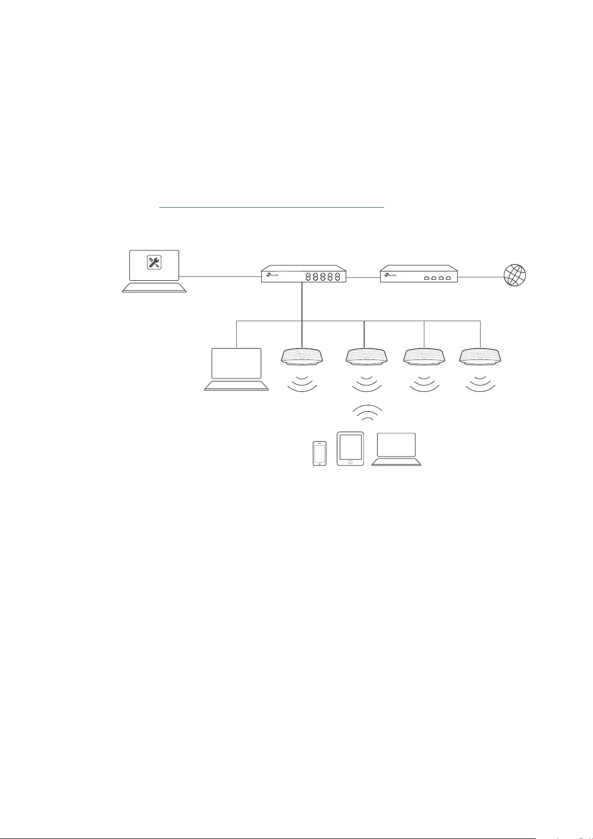
1.1.2 Management in Different Subnets
If your EAP Controller and EAPs are in different subnets, refer to the following topology.
A router acts as the gateway of the network. A layer 3 switch acts as a DHCP server to assign IP
addresses to EAPs and clients. The Controller Host and the EAPs are connected to the switch’s
different network segments. To help the EAPs find the Controller Host, EAP Discover Utility should
be installed on Host B which is in the same subnet with the EAPs. For how to use EAP Discovery
Utility, refer to 1.3 Inform the EAPs the Controller Host’s Address for detailed instructions.
Host B
IP: 192.168.2.100/24
Layer 3 Switch
(DHCP Server)
LAN WAN
EAPs
Clients
Router
EAP Controller
EAP
Discovery Utility
Internet
Host A (Controller Host)
IP: 192.168.1.100/24
192.168.1.0/24
192.168.2.0/24
1.2 Install the EAP Controller
We provide EAP Controller for both Windows and Linux operating systems. Determine your
operation system and follow the introductions below to install EAP Controller.
1.2.1 Installation on Windows Host
Make sure your PC meets the following system requirements and then properly install the EAP
Controller software.
System Requirements
Operating System: Microsoft Windows XP/Vista/7/8/10.
Web Browser: Mozilla Firefox 32 (or above), Google Chrome 37 (or above), Opera 24 (or above), or
Microsoft Internet Explorer 11 (or above).

4
Note:
We recommend that you deploy the EAP controller on a 64-bit operating system to guarantee the software
stability.
Install the EAP Controller
Download the installation file of EAP Controller from the website
http://www.tp-link.com/en/
download/EAP-Controller.html.
Then follow the instructions to properly install the EAP Controller
software. After successful installation, a shortcut icon of the EAP Controller will be created on
your desktop.
1.2.2 Installation on Linux Host
Make sure your PC meets the following system requirements and then install the EAP Controller
software.
System Requirements
Operating System: 64-bit Linux operating system, including Ubuntu 14.04/16.04/17.04, CentOS
6.x/7.x and Fedora 20 (or above).
Web Browser: Mozilla Firefox 32 (or above), Google Chrome 37 (or above), Opera 24 (or above), or
Microsoft Internet Explorer 11 (or above).
Install the EAP Controller
Download the installation file of EAP Controller from our website
http://www.tp-link.com/en/
download/EAP-Controller.html
.
Follow the steps below to install EAP Controller on your Linux PC:
1. Make sure your PC is runnning in root mode. You can use this command to enter root mode:
sudo
2. Extract the tar.gz file using the command:
tar zxvf EAP_Controller_v2.5.3_linux_x64.tar.gz
3. Install EAP Controller using the command:
sudo ./install.sh
Tips:
· To uninstall EAP Controller, go to the insatllation path: /opt/tplink/EAPController, and run the command:
sudo ./uninstall.sh.
· During uninstallation, you can choose whether to backup the database.The backup folder is /opt/tplink/eap_
db_backup.
· During installation, you will be asked whether to restore the database if there is any backup database in the
folder /opt/tplink/eap_db_backup.
5
1.3 Inform the EAPs of the Controller Host’s Address
If your Controller Host and EAPs are in the same network segment, you can skip this section.
If your Controller Host and EAPs are in different subnets, you need to install EAP Discovery Utility
on a host that is in the same network segment with the EAPs. EAP Discovery Utility can help the
EAPs find the Controller Host.
System Requirements
WinXP/Vista/7/8/8.1/10/Server2008/Server2012
Mac OS X 10.7/10.8/10.9/10.10/10.11
Install and Use EAP Discovery Utility
Follow the steps below to install EAP Discovery Utility and use it to inform the EAPs of the Controller
host’s IP address:
1. Download the installation file from our website
http://www.tp-link.com/en/download/EAP-
Controller.html#EAP_Discovery_Tool
. Then follow the instructions to properly install EAP
Discovery Utility.
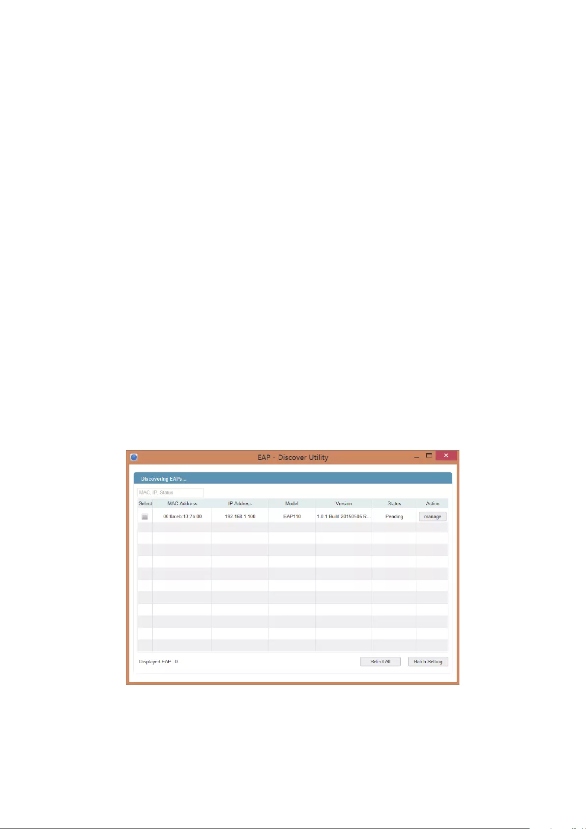
2. Open the EAP Discovery Utility and the following window will pop up. This window shows the
information of all EAPs in the same LAN.
3. Click manage in the Action column or select multiple EAPs and click Batch Setting.

6
4. Enter the hostname or IP address of the Controller Host.
5. Enter the EAP’s username and password (both are admin by default).
6. Click Apply to inform the EAP of the Controller’s hostname or IP address. And then the
connection can be established between the EAP and the Controller Host.
1.4 Start and Log in to the EAP Controller
Launch the software on the Controller Host and follow the instructions to complete the basic
configurations, and then you can log in to the management interface.
1.4.1 Launch the EAP Controller
Launch EAP Controller on Windows Host
To launch EAP Controller on a Windows host, double click the icon and the following window will
pop up. You can click Hide to hide this window but do not close it. After a while, your web browser
will automatically open.
7
Note:
· If your browser does not open automatically, click Launch a Browser to Manage Wireless Network. You can
also launch a web browser and enter http://127.0.0.1:8088 in the address bar.
· If your web browser opens but prompts a problem with the website’s security certificate, click Continue.
Launch EAP Controller on Linux Host
To launch EAP Controller on a Linux host, follow the steps below:
1. Start the EAP Controller service using the command: tpeap start.
2. Launch a web browser and enter http://127.0.0.1:8088 in the address bar to visit the web page of
EAP Controller.
Tips:
You can also use the following commands to stop the service or view the service status:
· To stop the service: tpeap stop
· To view the service status: tpeap status
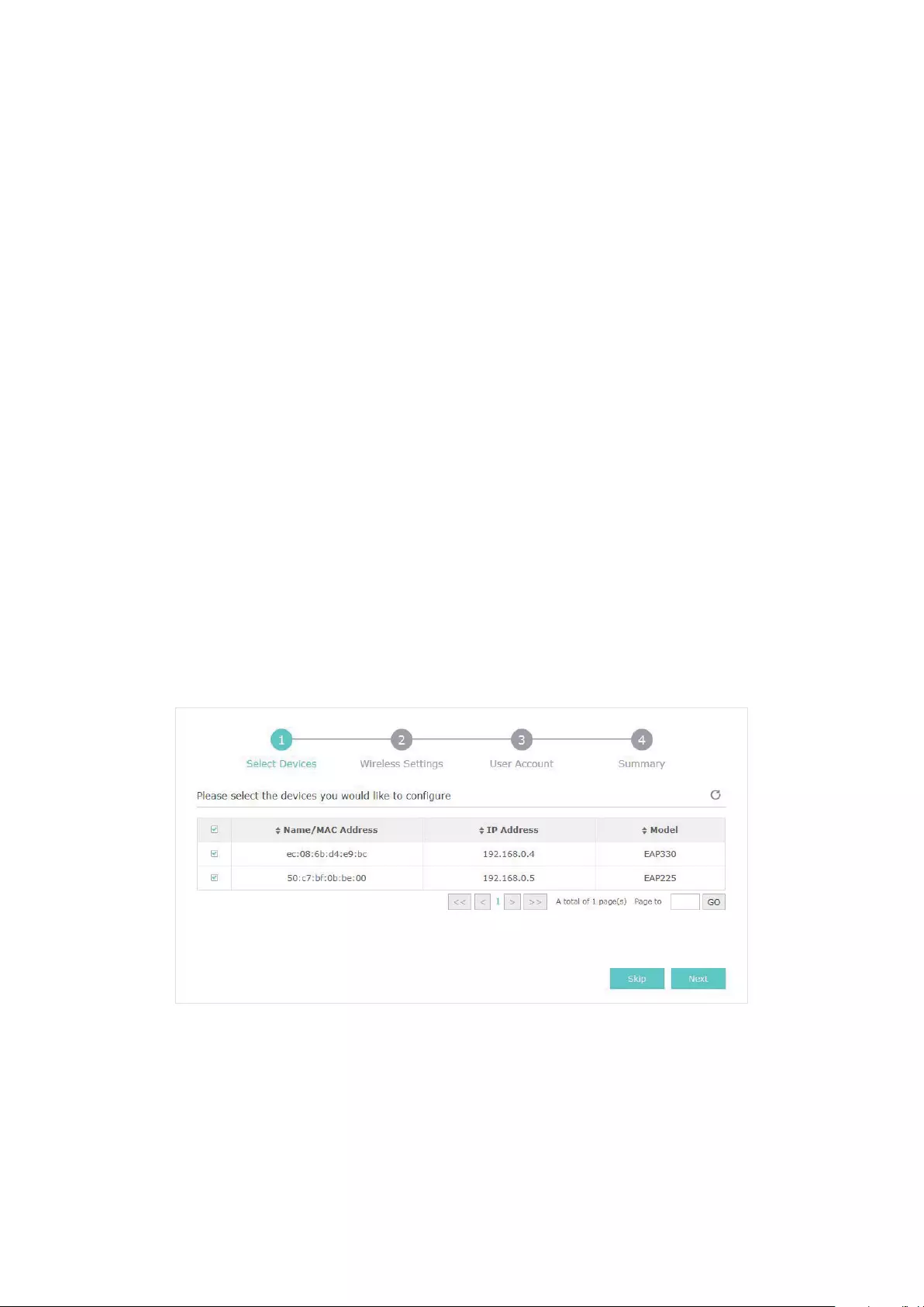
1.4.2 Do the Basic Configurations
In the web browser you can see the configuration page. Follow the setup wizard to complete the
basic settings for EAP Controller.
1. The EAP Controller displays all the detected EAPs in the network. Select the one or more EAPs
to be managed and click Next.
2. Set the SSID name (wireless network name) and password for the EAPs to be managed. The EAP
Controller will create two wireless networks, a 2.4GHz one and a 5GHz one both encrypted in the
WPA2-PSK mode. Click Next.

8
3. Specify a username and a password to create an administrator account. Specify the email
address to receive the notification emails and reset your password if necessary. Click Next.
Note:
After logging into the EAP Controller, please set a mail server so that you can receive the notification emails
and reset your password in case that you forget the password. Please refer to Configure Mail Server.
4. Review your settings and click Finish.
9
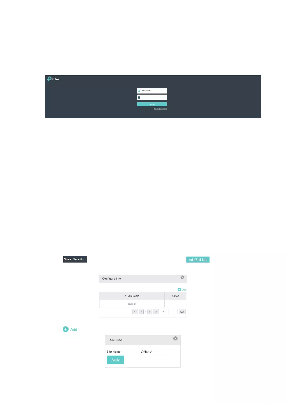
1.4.3 Log in to the Management Interface
Once the basic configuration is finished, the browser will be redirected to the following page. Log
in to the management interface of EAP Controller with the username and password you have set in
the basic configuration.
Note::
In addition to the Controller Host, other hosts in the same LAN can also manage EAP devices via remote
access to the Controller Host. For example, when the IP address of the Controller Host is 192.168.0.100
and the EAP Controller is running normally on this host, you can enter https://192.168.0.100:8043/login, or
https://192.168.0.100:8043, or http://192.168.0.100:8088 in the web browser of other hosts in the same LAN
to log into the management interface and manage EAP devices.
1.5 Create Sites and Adopt EAPs
The EAP Controller can manage multiple EAP networks, which are called sites. Multiple sites are
logically separated, and each site has its own configurations. There is an initial site named Default.
If you have no need to manage EAPs with different sites, you can use the default site and skip the
Create Sites section. However, Adopt the EAPs is a necessary step to manage the EAPs.
1.5.1 Create Sites
Follow the steps below to add sites.
1. Click in the top left corner of the page and select , and then the following
window will pop up.
2. Click and set a name for the site.

10
3. Click Apply to create the site.
1.5.2 Adopt the EAPs
The EAP Controller can discover all EAP devices currently connected in the network and display
their connection statuses. All the EAPs are in Pending status when first discovered by the EAP
Controller. To manage the EAPs, you need to adopt them. In the quick setup process, the EAP
Controller will automatically adopt the selected EAPs using the default username and password
(both are admin). However, if you have changed the username or password of your EAPs before, the
EAP Controller cannot automatically adopt the them.
To ensure that all EAPs are adopted, follow the steps below:
1. Select a site and go to Access Points > Pending. The table displays all the EAPs that have not
been adopted.
2. Click the Retry button in the Action column and enter the current username and password of the
EAP. Click Apply.
Tips:
· If you have a new discovered EAP, you can click the Adopt button in the Action column to adopt the EAP. The
EAP Controller will automatically adopt the EAP using the default username and password (both are admin).
· If you have multiple new discovered EAPs, and all of them have the default username and password (both
are admin), you can click the Batch Adopt button to adopt them all at once. But if there are any EAPs with the
Retry button, it means that the username and password of these EAPs have been changed. You need to first
adopt them before batch adopt the rest EAPs.
3. Wait for a moment, the EAPs will be adopted and the status will change to Connected. All the
EAPs’ username and password will become the same as those of the Controller’s administrator
account you created in the Basic Configuration.
Tips:
If you want to change the EAPs’ username and password, please refer to Device Account.
11
1.6 Monitor and Manage the EAPs
When all the configurations above are finished, you can centrally monitor and manage the EAPs via
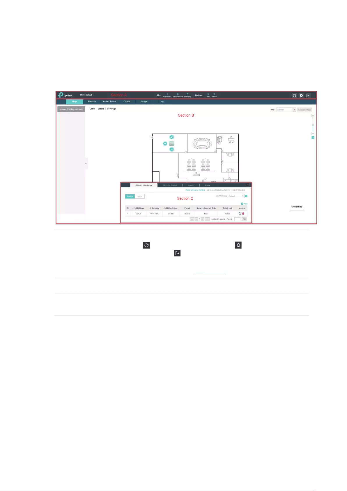
the EAP Controller’s management interface. The management interface is mainly divided into three
sections as the following screen.
Section A In Section A, you can check the status of EAPs and clients in the network. Also,
you can click to refresh the current page, click to globally configure the
wireless network, and click to sign out from the management interface.
Furthermore, the Sites allows you to group your EAPs and manage them in
batches. To configure sites, refer to Create Sites.
Section B In Section B, you can centrally monitor and manage the EAPs and clients.
Section C In Section C, you can globally configure the wireless network. The global
configurations will take effect on all the adopted EAPs.

12
2 Monitor and Manage the Network
With the EAP Controller you can monitor the EAP devices and centrally manage your wireless
network. This chapter includes the following sections:
·
Monitor the Network with the Map
·
View the Statistics of the Network
·
Monitor and Manage the EAPs
·
Monitor and Manage Clients
·
View Clients Statistics during the Specified Period
·
Manage the Rogue APs List
·
View Past Guest Authorization
·
View Logs
·
View Alerts

13
2.1 Monitor the Network with the Map
You can upload your local map images and monitor the status and coverage range of each EAP with
the map. When you initially launch the EAP Controller, a default map is displayed as the following
figure shows. Follow the instructions below to add your own map and manage the EAPs via the map.
2.1.1 Add a Map
Prepare a map image in .jpg, .gif, or .webp format. And then follow the steps below to add the map to
the EAP Controller.
1. Click Configure Maps on the upper right corner of map and click Add.
2. Enter the map description, select your map image, and click Create.
3. Select your local map from the drop-down list on the upper right corner of map area.
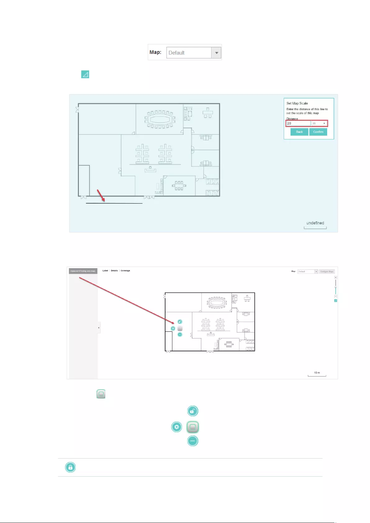
14
4. Click . Draw a line on the map and enter the distance the line represents. Then the EAP
Controller will compute and generate the map scale automatically based on your configuration.
5. Drag the EAPs from the Unplaced APs list to the appropriate locations on the map according to
their actual locations.
You can click to reveal additional options:
Lock the selected EAP in the current location on the map.

15
Unlock the selected EAP and you can drag it to another location.
Display the EAP’s details and configure the wireless parameters. Refer to
Configure the EAPs Separately.
Remove the selected EAP back into the Unplaced APs list.
2.1.2 Monitor the EAPs on the Map
Click any of the following options to display EAP Label, Details, and Coverage on the map.
Label Display the EAP’s name. The default name is the MAC address of the EAP.
Details Display the EAP’s name, MAC address, IP address, transmitting/receiving
channel, number of connected users, and number of connected guests.
Coverage Display a visual representation of the wireless range covered by EAPs. The
actual signal coverage may be smaller than the visual coverage on the map
because the obstacles around the EAPs will weaken the signal.
16
2.2 View the Statistics of the Network
The EAP Controller collects all statistics of the managed EAPs and displays the statistical
information via graphs, pie charts and tables, providing an overview of your wireless network.
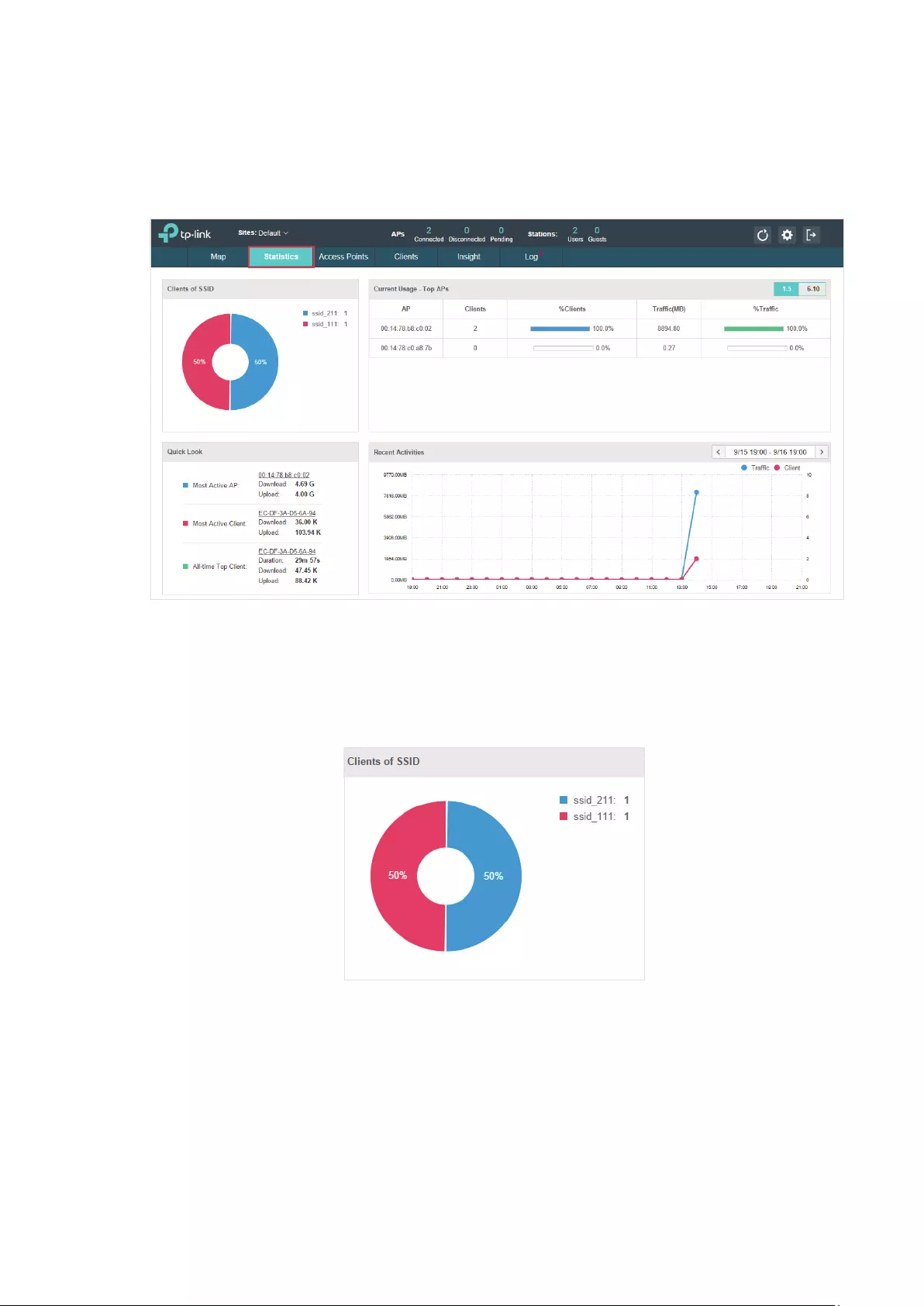
2.2.1 View the Client Distribution on SSID
A visual pie chart represents the client distribution on each SSID. For example, the ssid_211 has
one client, which occupies 50% of all the clients.
2.2.2 Have a Quick Look at EAPs and Clients
This tab displays the Most Active AP, the Most Active Clients and the All-Time Top Client. You can
click the MAC address of the EAP or the client to see more details.

17
Most Active AP The current connected AP with the maximum traffic.
Most Active
Client
The current connected client with the maximum traffic.
All-time Top
Client
The client with the maximum traffic among all the clients that have ever
accessed the EAP network.
2.2.3 View Current Usage-Top EAPs
This tab lists the hostname, the number of connected clients and the data traffic condition of the
ten APs with the most traffic currently.
Clients The amount of clients connected to this EAP.
%Clients The proportion of current connected clients to the Top EAPs’ total client
amount.
Traffic The total amount of data transmitted by this EAP, which equals the sum of the
transmission traffic of all the current clients that connect to the AP.
%Traffic The proportion of the EAP’s current data transmission amount to the Top EAPs’
total transmission amount.
2.2.4 View Recent Activities
The Recent Activities statistics can be toggled between a view for the past specific 24 hours and
one for the past specific 30 days.
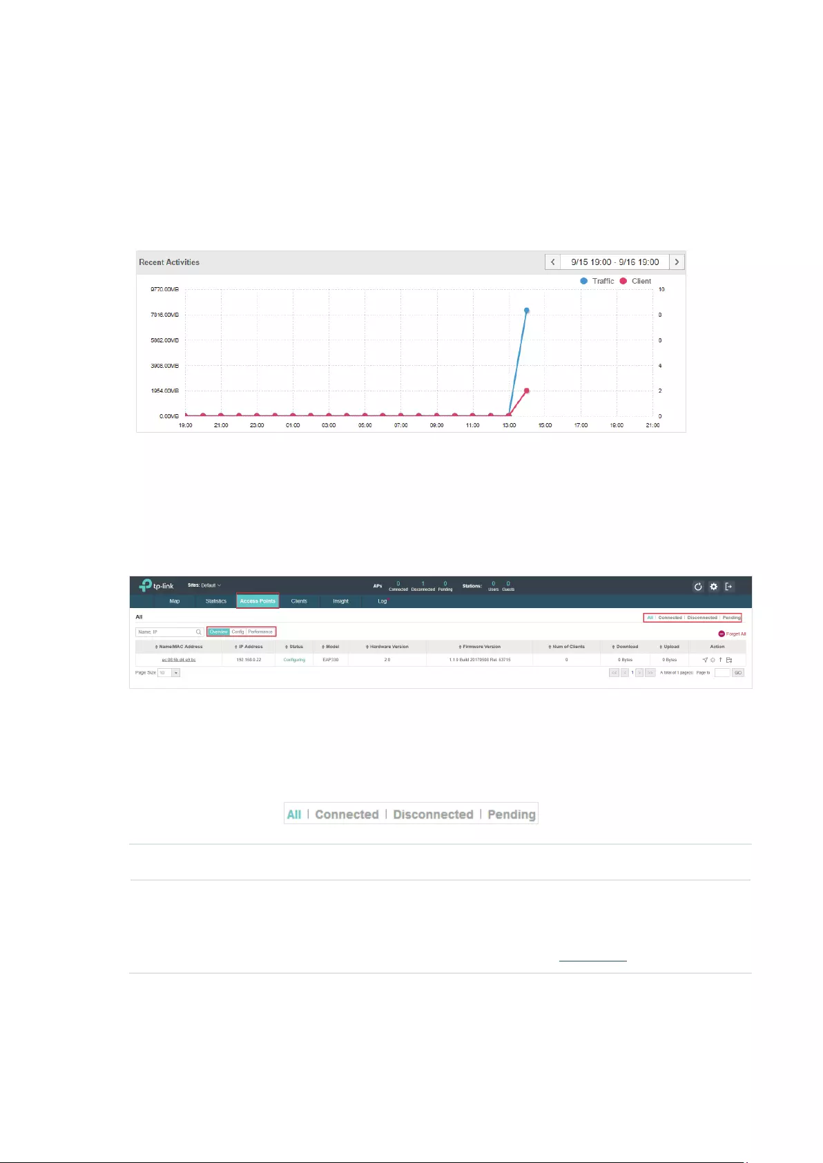
18
The left ordinate axis indicates the traffic and the right one represents the number of the clients.
The abscissa axis shows the selected time period. Traffic indicates a visual graph of the network
traffic during the selected time period. Client indicates a visual graph of the number of the
connected clients during the selected time period. For example, the statistics information at 10:00
indicates the traffic size and client number from 9:00 to 10:00. In the following figure, at 10 o’clock,
the traffic is about 8 and there is 1 client connected to the AP.
2.3 Monitor and Manage the EAPs
The EAP Controller can discover all the EAP devices currently connected to the network and display
the information about them on the Access Points page.
2.3.1 Manage the EAPs in Different Status
According to their connection status, all the EAPs are divided into three categories: connected,
disconnected and pending. You can view the EAPs in different status on different pages:
All Displays the information of all the EAPs in different status.
Pending Displays the pending EAPs.
All the EAPs are in pending state by default when first discovered by the EAP
Controller, and only after they are adopted and connected, you can monitor and
manage them. To adopt pending EAPs, please refer to Adopt EAPs.

19
Connected Displays the connected EAPs.
Only connected EAPs can be managed. After you adopt a pending EAP, its status will
become provisioning and then connected. A connected EAP will turn into a pending
one after you forget this EAP. You can refer to Forget this AP to forget a EAP or click
Forget All on the page to forget all the connected EAPs.
Disconnected Displays the disconnected EAPs.
If a connected or pending EAP powers off, it will be disconnected. When a
disconnected EAP is reset to factory default settings or you forget it, it will turn into a
pending one again. You can refer to Forget this AP to forget a EAP or click Forget All
on the page to forget all the disconnected EAPs.
2.3.2 View the Detailed Information of EAPs
You can click Overview, Config, and Performance tab to view different detailed information of
EAPs.
Overview Overview displays the EAP’s name/MAC address, IP address, status, model, software
version, number of connected clients and download/upload bytes.
Config Config displays the EAP’s name/MAC address, IP address, status, model, software
version, WLAN Group bounded with the 2G and 5G of the EAP, and radio of the 2G and
5G.
Performance Performance displays the EAP’s name/MAC address, IP address, status, model,
software version, number of connected 2G clients and 5G clients, TX(Downloaded
Traffic), RX(Uploaded Traffic), TX 2G and TX 5G.
2.3.3 Manage the EAPs in the Action Column
You can execute the corresponding operation to the EAP by clicking an icon in the Action column.
Locate the EAP in the map.
Reboot the EAP.

20
Upgrade the EAP.
Click Browse to locate and choose the upgrade file in your computer, then click
Upgrade to install the latest EAP firmware. The Status will appear as Upgrading until
the process is complete and the EAP reconnects to the EAP Controller.
Note:
· Only managed EAPs can be rebooted or upgraded.
· If you want to login to the EAP’s own management interface, you need to forget the EAP before that.
2.4 Monitor and Manage Clients
The Clients tab displays the clients connected to the EAP network.
2.4.1 View the Current Information of Clients
The clients are divided into two types: User and Guest. Users are the clients connected to the EAP
wireless network without the Portal Authentication. Guests are the clients connected to the EAP
wireless network with the Portal Authentication.
You can click the following tabs to respectively view the detailed information of users and guests.
All Clients The page will display the information of all clients including users and guests.
Users The page will display the information of Users.
Guests The page will display the information of Guests.
2.4.2 Manage Clients in the Action Column
You can execute the corresponding operation to the EAP by clicking an icon in the Action column:
21
Reconnect the client to the network.
Restrict the client’s access to the network.
If the client is Guest, you can click this icon to cancel the authorization for it.
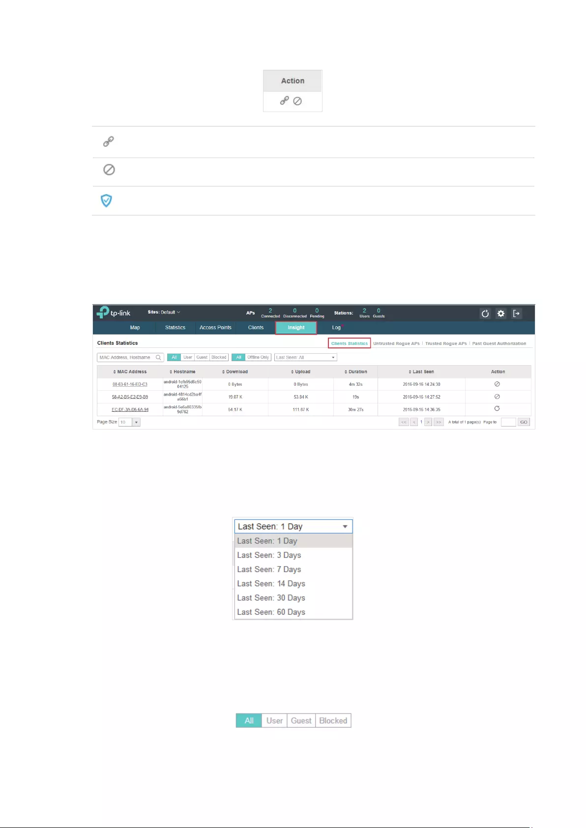
2.5 View Clients Statistics During the Specified Period
The Clients Statistics page under the Insight tab displays the information of clients that have
connected to the EAPs network during a specified period.
2.5.1 Select a Specified Period
Select a period from the drop-down menu. Then the page will display clients that have connected to
the EAPs network during the period.
2.5.2 View the History Information of Clients
You can click the client’s MAC address to get its connection history or click the following tabs to
view the information of different types of clients:
22
All The page will display the history information of all the clients.
User The page will display the history information of Users.
Users are the clients connected to the EAP wireless network without the Portal
Authentication.
Guest The page will display the history information of Guests.
Guests are the clients connected to the EAP wireless network with the Portal Authentication.
Blocked The page will display the clients that have been blocked.
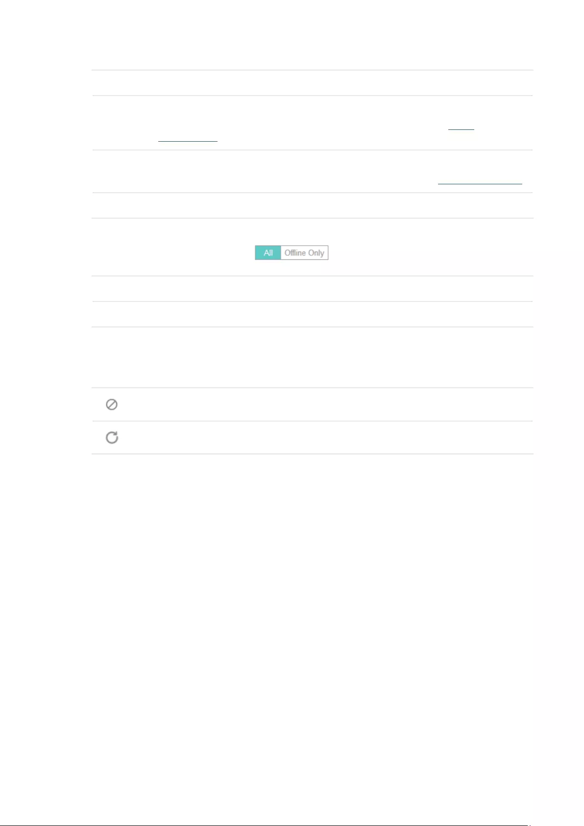
All The page will display the history information of all clients.
Offline Only The page will display the history information of the offline clients.
2.5.3 Manage Clients in the Action Column
You can execute the corresponding operation to the EAP by clicking an icon in the Action column:
Block the client’s access to the network.
Resume the client’s access.
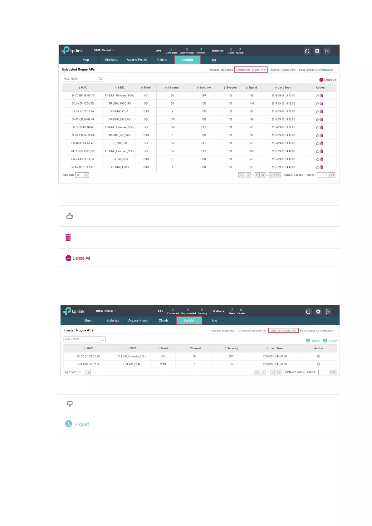
2.6 Manage the Rogue APs List
A Rogue AP is an access point that has been installed on a secure network without explicit
authorization from a system administrator. The EAP Controller can scan all channels to detect
all nearby EAPs. If rogue APs are detected, they will be shown on the Untrusted Rogue APs list.
Besides, you can move the untrusted rogue APs to the Trusted Rogue APs list.
2.6.1 Manage the Untrusted Rogue APs List
The Untrusted Rogue APs page displays the detailed information of untrusted rogue APs.
23
You can execute the corresponding operation to the EAP by clicking an icon in the Action column:
Move the untrusted rogue AP to the Trusted Rogue APs list.
Delete this record.
Delete all records.
2.6.2 Manage the Trusted Rogue APs List
The Trusted Rogue APs page displays the detailed information of trusted rogue APs.
You can execute the corresponding operation to the EAP by clicking an icon in the Action column:
Move the trusted rogue AP to the Untrusted Rogue APs list.
Export and download the current Trusted Rogue APs list and save it on your PC.

24
Import a saved Trusted Rogue APs list. If the MAC address of an AP appears in list, it will
not be detected as a rogue AP.
Please follow the steps below:
1. Select Replace (replace the current Trusted Rogue APs list with the one you import) or
Merge (add the APs in the file to the current Trusted Rogue APs list).
2. Click Browse to locate the file and choose it.
3. Click Import to import the Trusted Rogue APs list.
2.7 View Past Guest Authorization
The Past Guest Authorization page displays the details about all the clients that accessed the
network during a certain time period. You can select a period in the drop-down list.
2.8 View Logs
The logs of the EAP Controller can effectively record, classify and manage the system information
of the managed EAPs, providing powerful support for network administrator to monitor network
operation and diagnose malfunctions. The Logs page displays EAP’s MAC address, level, occurred
time and content.
25
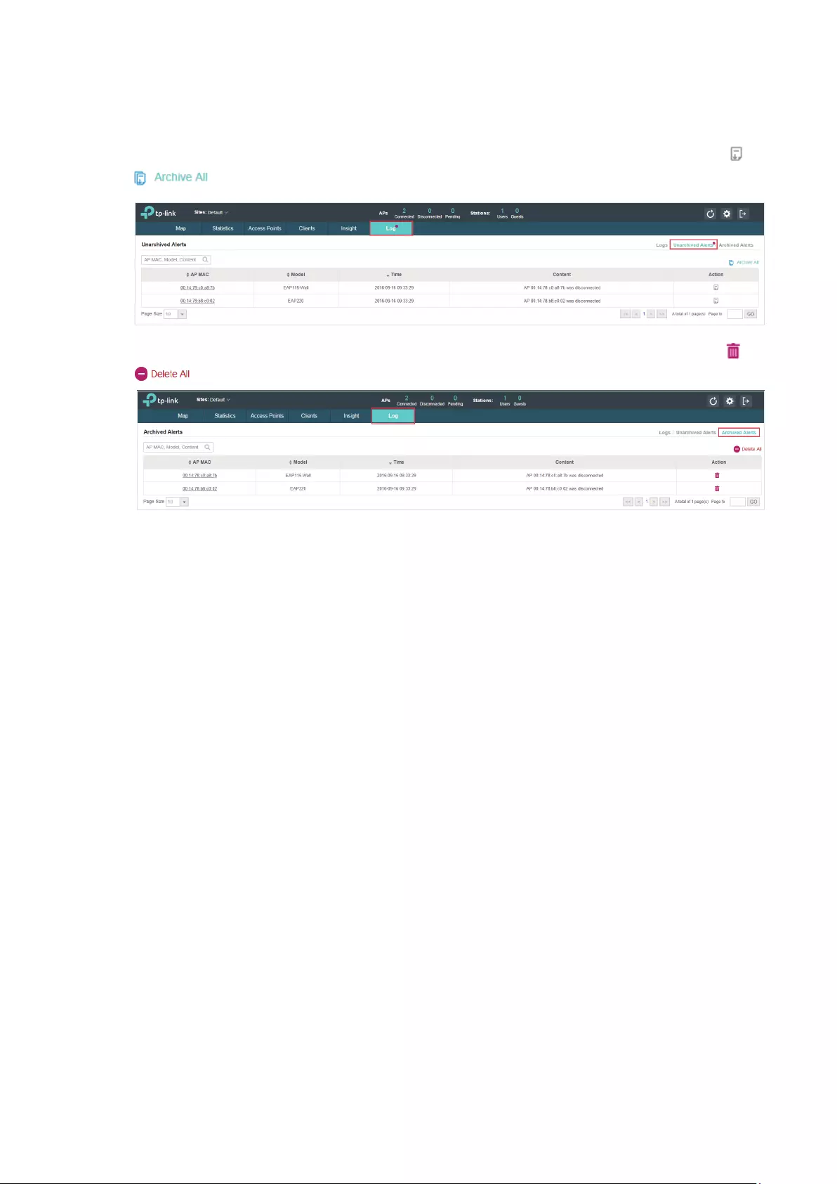
2.9 View Alerts
You can see the status change of your EAPs on the Unarchived Alerts page. You can click or
to move unarchived alerts to the Archived Alerts page.
As follows, the Archived Alerts page displays the alerts archived by you. You can click or
to delete the records.

26
3 Congure the EAPs Globally
This chapter introduces the global configurations applied to all the managed EAPs. To configure a
specific EAP, please refer to Chapter 4 Configure the EAPs Separately.
In global configurations, you can configure the following items:
·
Wireless Network
·
Access Control
·
Portal Authentication
·
Free Authentication Policy
·
MAC Filter
·
Scheduler
·
System

27
3.1 Wireless Network
In addition to the wireless network you created in Quick Start, you can add more wireless networks
and configure the advanced wireless parameters to improve the quality of the wireless network.
3.1.1 Add Wireless Networks
To add wireless networks, follow the steps below.
1. Go to Wireless Settings > Basic Wireless Setting.
2. Select a band frequency and click at the right of to add a WLAN
group. If you have no need to group your wireless networks, you can use the default WLAN
group and skip this step.
3. Specify a name for the group and click Apply.
4. Select the brand frequency and WLAN group .
5. Click to add an SSID to the specific WLAN group.
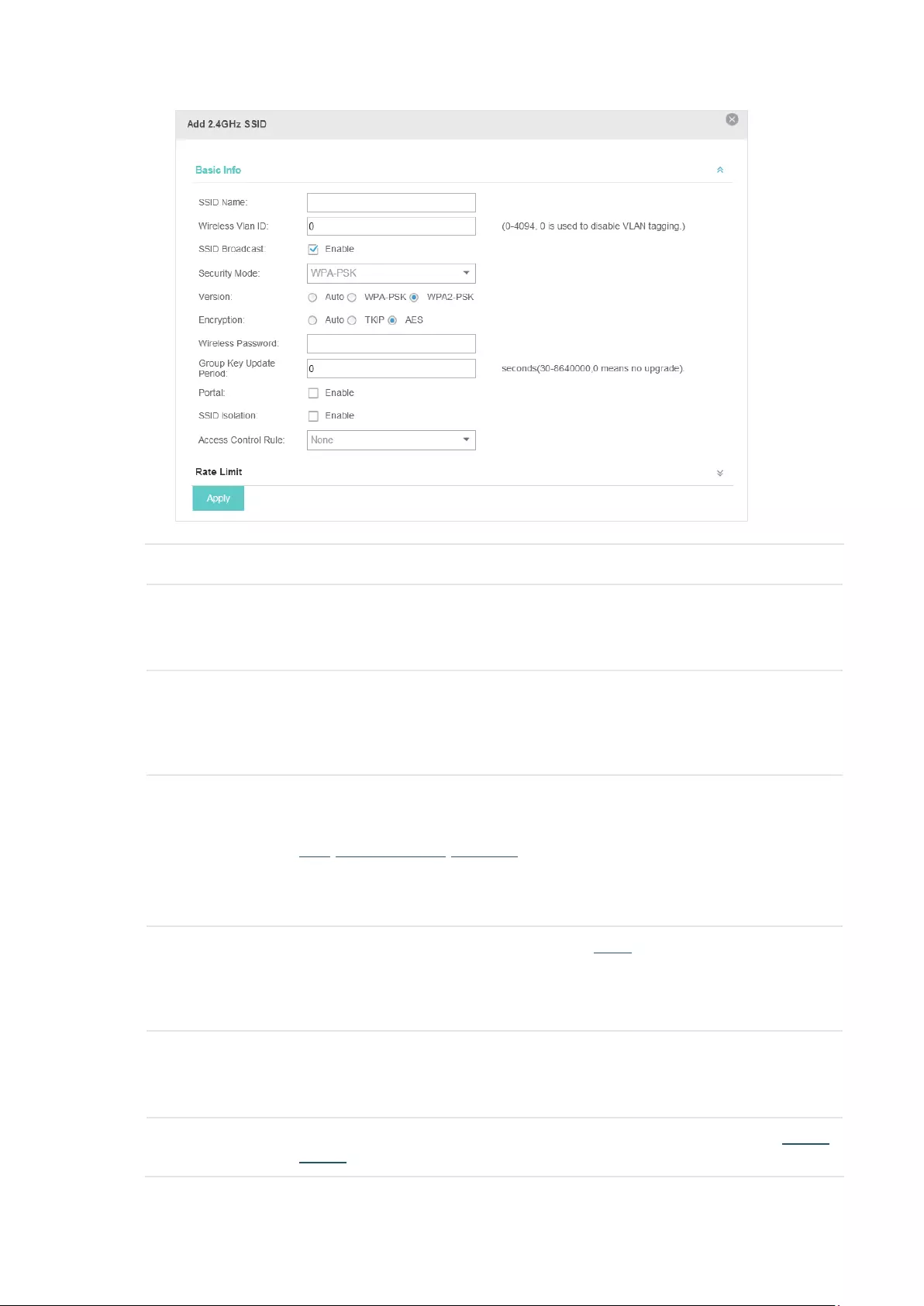
6. Configure the parameters in the following window.
28
SSID Name Enter an SSID name contains up to 32 characters.
Wireless Vlan ID Set a VLAN ID for the wireless network. Wireless networks with the same VLAN ID
are grouped to a VLAN.
The value ranges from 0 to 4094. 0 means VLAN function is disabled.
SSID Broadcast With the option enabled, EAPs will broadcast the SSID to the nearby hosts, so that
those hosts can find the wireless network identified by this SSID. If this option is
disabled, users must enter the SSID manually to connect to the EAP.
Enabled by default.
Security Mode Select the security mode of the wireless network.
None: The hosts can access the wireless network without authentication.
WEP/WPA-Enterprise/WPA-PSK: The hosts need to get authenticated before
accessing the wireless network. For the network security, you are suggested to
encrypt your wireless network. Settings vary in different security modes and the
details are in the following introduction.
Portal With the option enabled, the configurations in Portal will be applied. Portal provides
authentication service for the clients who just need temporary access to the
wireless network, such as the customers in shopping mall and restaurant.
Disabled by default.
SSID Isolation With the option enabled, the devices connected in the same SSID of the same AP
cannot communicate with each other.
Disabled by default.
Access Control Select an Access Control rule for this SSID. For more information, refer to Access
Control.

29
Following is the detailed introduction of WEP, WPA-Enterprise and WPA-PSK.
WEP
WEP is based on the IEEE 802.11 standard and less safe than WPA-Enterprise and WPA-PSK.
Note:
WEP is not supported in 802.11n mode or 802.11ac mode. If WEP is applied in 802.11n, 802.11 ac or 802.11n/
ac mixed mode, the clients may not be able to access the wireless network. If WEP is applied in 11b/g/n mode
(2.4GHz) or 11a/n (5GHz), the EAP device may work at a low transmission rate.
Type Select the authentication type for WEP.
Auto: The EAP Controller can select Open System or Shared Key automatically
based on the wireless station’s capability and request.
Open System: Clients can pass the authentication and associate with the wireless
network without password. However, correct password is necessary for data
transmission.
Shared Key: Clients have to input password to pass the authentication, otherwise it
cannot associate with the wireless network or transmit data.
Key Selected Select one key to specify. You can configure four keys at most.
WEP Key Format Select ASCII or Hexadecima as the WEP key format.
ASCII: ASCII format stands for any combination of keyboard characters of the
specified length.
Hexadecimal: Hexadecimal format stands for any combination of hexadecimal
digits (0-9, a-f, A-F) with the specified length.
Key Type Select the WEP key length for encryption.
64Bit: Enter 10 hexadecimal digits or 5 ASCII characters.
128Bit: Enter 26 hexadecimal digits or 13 ASCII characters.
152Bit: Enter 32 hexadecimal digits or 16 ASCII characters.
Key Value Enter the WEP keys. The length and valid characters are affected by key type.
30
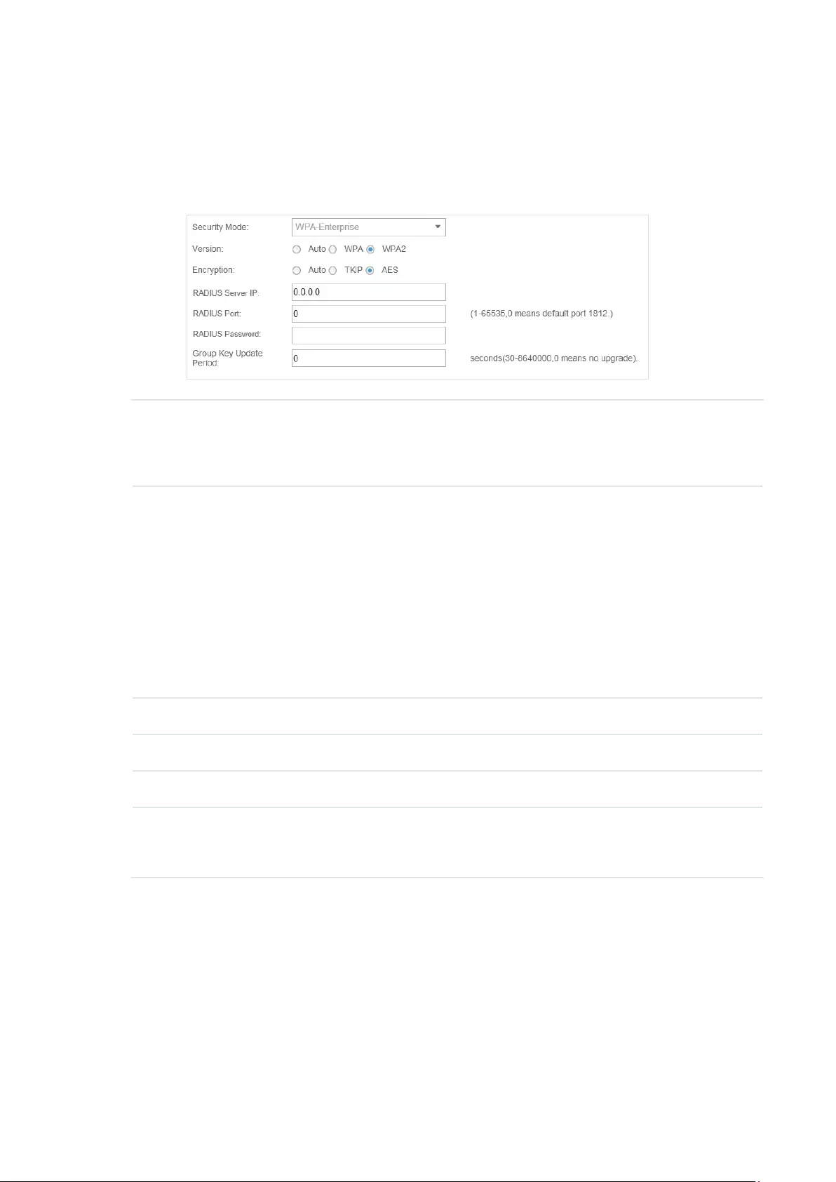
WPA-Enterprise
The WPA-Enterprise mode requires a RADIUS server to authenticate clients. Since the WPA-
Enterprise can generate different passwords for different clients, it is much safer than WPA-PSK.
However, it costs much more to maintain and is usually used by enterprise.
Version Select the version of WPA-Enterprise.
Auto: The EAP will automatically choose the version used by each client device.
WPA/WPA2: Two versions of Wi-Fi Protected Access.
Encryption Select the Encryption type.
Auto: The default setting is Auto and the EAP will select TKIP or AES
automatically based on the client device’s request.
TKIP: Temporal Key Integrity Protocol. TKIP is not supported in 802.11n mode,
802.11ac mode or 802.11n/ac mixed mode. If TKIP is applied in 802.11n,
802.11 ac or 802.11n/ac mixed mode, the clients may not be able to access the
wireless network of the EAP. If TKIP is applied in 11b/g/n mode (2.4GHz) or 11a/
n mode(5GHz), the device may work at a low transmission rate.
AES: Advanced Encryption Standard. We recommend you select AES as the
encryption type because it is more secure than TKIP.
RADIUS Server IP Enter the IP address of the RADIUS Server.
RADIUS Port Enter the port number of the RADIUS Server.
RADIUS Password Enter the shared secret key of the RADIUS server.
Group Key Update
Period
Specify a group key update period, which instructs the EAP how often it should
change the encryption keys. The value can be either 0 or 30~8640000 seconds.
0 means no change of the encryption key anytime.
31
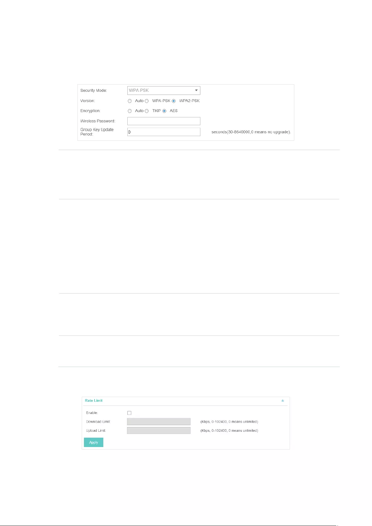
WPA-PSK
Based on a pre-shared key, WPA-PSK is characterized by high safety and simple settings and is
mostly used by common households and small businesses.
Version Select the version of WPA-PSK.
Auto: The EAP will automatically choose the version for each client device.
WPA-PSK: Pre-shared key of WPA.
WAP2-PSK: Pre-shared key of WPA2.
Encryption Select the Encryption type.
Auto: The default setting is Auto and the EAP will select TKIP or AES automatically
based on the client request.
TKIP: Temporal Key Integrity Protocol. TKIP is not supported in 802.11n mode,
802.11ac mode or 802.11n/ac mixed mode. If TKIP is applied in 802.11n, 802.11
ac or 802.11n/ac mixed mode, the clients may not be able to access the wireless
network of the EAP. If TKIP is applied in 11b/g/n mode (2.4GHz) or 11a/n mode(5GHz),
the device may work at a low transmission rate.
AES: Advanced Encryption Standard. We recommend you select AES as the
encryption type for it is more secure than TKIP.
Wireless
Password
Configure the wireless password with ASCII or Hexadecimal characters.
For ASCII, the length should be between 8 and 63 characters with combination of
numbers, letters (case-sensitive) and common punctuations. For Hexadecimal, the
length should be 64 characters (case-insensitive, 0-9, a-f, A-F).
Group Key
Update Period
Specify a group key update period, which instructs the EAP how often it should
change the encryption keys. The value can be either 0 or 30~8640000 seconds. 0
means the encryption keys will not be changed all the time.
7. Enable Rate Limit for the clients to guarantee the network balance. Enter the value for Download
Limit and Upload Limit. 0 means unlimited.
8. Click Apply to add the new SSID.
32
3.1.2 Configure Advanced Wireless Parameters
Proper wireless parameters can improve the network’s stability, reliability and communication
efficiency. The advanced wireless parameters consist of Beacon Interval, DTIM Period, RTS
Threshold, Fragmentation Threshold and Airtime Fairness.
To configure the advanced wireless parameters, follow the steps below.
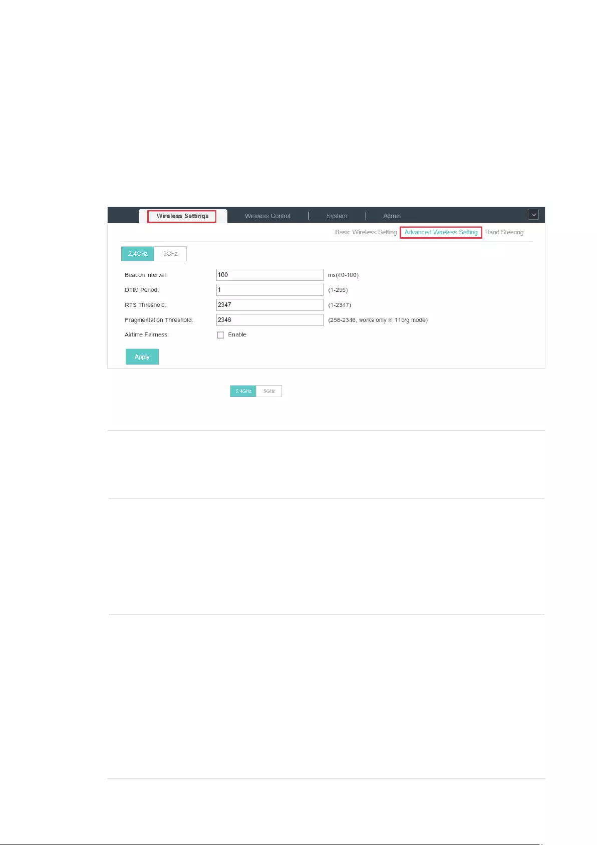
1. Go to Wireless Settings > Advanced Wireless Setting.
2. Select the band frequency .
3. Configure the following parameters.
Beacon Interval Beacons are transmitted periodically by the EAP device to announce the
presence of a wireless network for the clients. Beacon Interval value determines
the time interval of the beacons sent by the device.
You can specify a value between 40 and 100ms. The default is 100ms.
DTIM Period The DTIM (Delivery Traffic Indication Message) is contained in some Beacon
frames. It indicates whether the EAP device has buffered data for client devices.
The DTIM Period indicates how often the clients served by this EAP device
should check for buffered data still on the EAP device awaiting pickup.
You can specify the value between 1-255 Beacon Intervals. The default value is 1,
indicating clients check for buffered data on the EAP device at every beacon. An
excessive DTIM interval may reduce the performance of multicast applications,
so we recommend you keep it by default.
RTS Threshold RTS (Request to Send) can ensure efficient data transmission. When RTS is
activated, the client will send a RTS packet to EAP to inform that it will send data
before it send packets. After receiving the RTS packet, the EAP notices other
clients in the same wireless network to delay their transmitting of data and
informs the requesting client to send data, thus avoiding the conflict of packet.
If the size of packet is larger than the RTS Threshold, the RTS mechanism will be
activated.
If you specify a low threshold value, RTS packets are sent more frequently
and help the network recover from interference or collisions that might occur
on a busy network. However, it also consumes more bandwidth and reduces
the throughput of the packet. We recommend you keep it by default. The
recommended and default value is 2347.
33
Fragmentation
Threshold
The fragmentation function can limit the size of packets transmitted over the
network. If a packet exceeds the Fragmentation Threshold, the fragmentation
function is activated and the packet will be fragmented into several packets.
Fragmentation helps improve network performance if properly configured.
However, too low fragmentation threshold may result in poor wireless
performance caused by the extra work of dividing up and reassembling of
frames and increased message traffic. The recommended and default value is
2346 bytes.
Airtime Fairness With this option enabled, each client connecting to the EAP can get the same
amount of time to transmit data, avoiding low-data-rate clients to occupy
too much network bandwidth and improving the network throughput. We
recommend you enable this function under multi-rate wireless networks.
4. Click Apply.
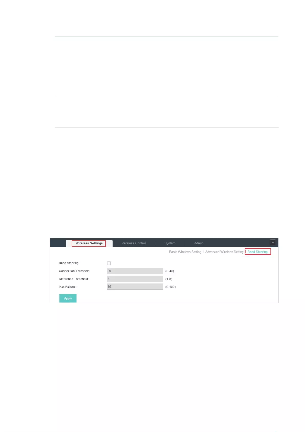
3.1.3 Configure Band Steering
A client device that is capable of communicating on both the 2.4GHz and 5GHz frequency bands
will typically connect to the 2.4 GHz band. However, if too many client devices are connected to an
EAP on the 2.4 GHz band, the efficiency of communication will be diminished. Band Steering can
steer clients capable of communication on both bands to the 5GHz frequency band which supports
higher transmission rates and more client devices, and thus to greatly improve the network quality.
To configure Band Steering, follow the steps below.
1. Go to Wireless Settings > Band Steering.
2. Check the box to enable the Band Steering function.
3. Configure the following parameters to balance the clients on both frequency bands:
34
Connection
Threshold/Difference
Threshold
When the number of clients on the 5GHz band reaches the value of
Connection Threshold and the difference value between the number
of clients on the 2.4GHz band and the 5GHz band reaches the value of
Difference Threshold, EAPs will refuse the requests of communication on
the 5GHz band from other clients and no longer steer other clients to the
5GHz band.
The value of Connection Threshold is from 2 to 40, and the default is 20.
The value of Difference Threshold is from 1 to 8, and the default is 4.
Max Failures If a client repeatedly attempts to associate with the EAP on the 5GHz band
and the number of rejections reaches the value of Max Failures, the EAP will
accept the request.
The value is from 0 to 100, and the default is 10.
4. Click Apply.
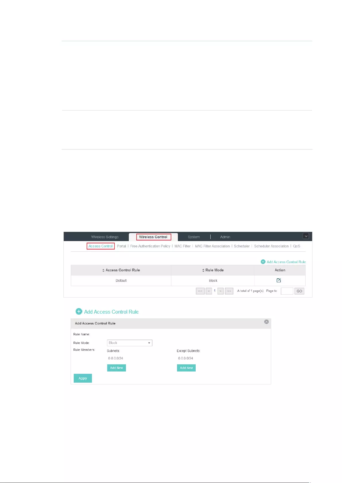
3.2 Access Control
Access Control is used to block or allow the clients to access specific subnets. To configure
Access Control rules, follow the steps below.
1. Go to Wireless Control > Access Control.
2. Click to add a new Access Control rule.
3. Configure the following parameters.
35
Rule Name Specify a name for this rule.
Rule Mode Select the mode for this rule.
Block: Select this mode to block the rule members to access the network.
Allow: Select this mode to allow the rule members to access the network.
Rule Memebers Subnets: Clients of the subnet will be controlled by the rule. Enter the subnet for
this rule in the format X.X.X.X/X and click . Up to 16 subnets can be added.
Except Subnets: Clients of the subnet will be controlled by the rule. Enter the
subnet that does not follow this rule in the format X.X.X.X/X and click . Up
to 16 subnets can be added.
The rule will not apply to the subnets that is in both the Subnets list and the
Except Subnets list.
4. Click Apply.
5. Go to Wireless Settings > Basic Wireless Setting and enable Access Control function of a
selected SSID.
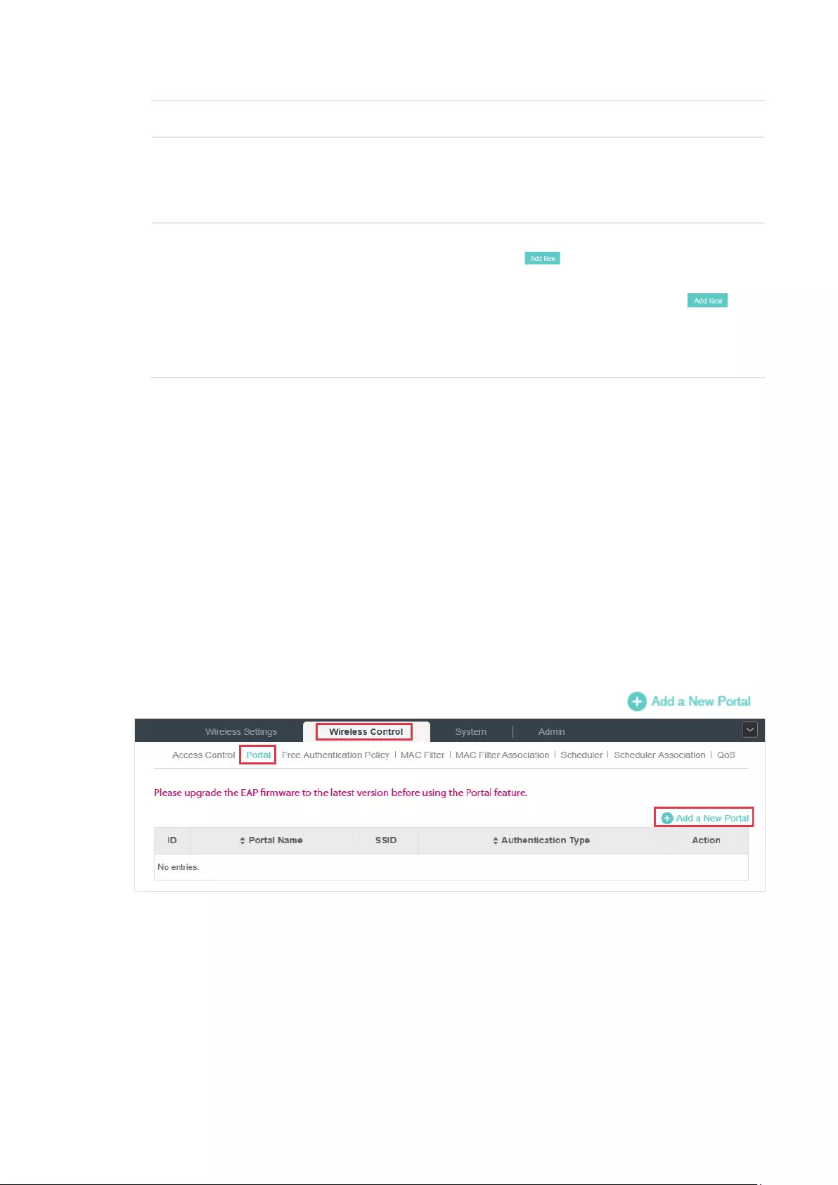
3.3 Portal Authentication
Portal authentication enhances the network security by providing authentication service to the
clients that just need temporary access to the wireless network. Such clients have to log into a
web page to establish verification, after which they will access the network as guests. What’s more,
you can customize the authentication login page and specify a URL which the newly authenticated
clients will be redirected to.
To configure Portal Authentication, go to Wireless Control > Portal and click .
36
Then the following window will pop up:
These authentication methods are available: No Authentication, Simple Password, Local User,
Voucher, SMS, Facebook, External RADIUS Server and External Portal Server. The following
sections introduce how to configure each Portal authentication.
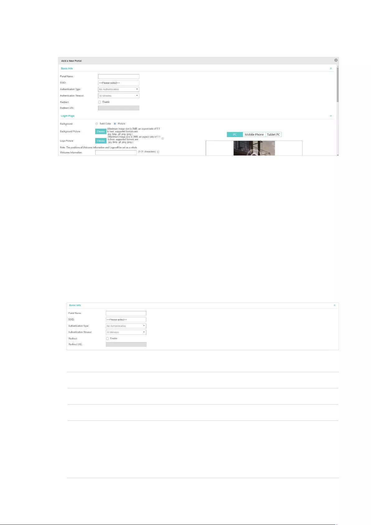
3.3.1 No Authentication
With No Authentication configured, clients can access the network without any authentication.
Follow the steps below to configure No Authentication:
1. Go to Wireless Settings > Basic Wireless Settings and create an SSID for the Portal.
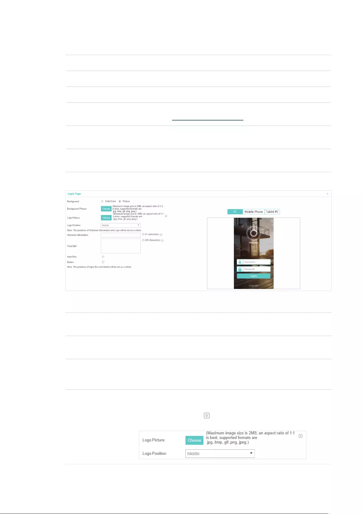
2. Go back to the Portal configruation page. In the Basic Info section, complete the basic settings
for the portal authentication.
Congure the following parameters:
Portal Name Specify a name for the Portal.
SSID Select an SSID for the Portal.
Authentication Type Select No Authentication.
Authentication
Timeout
The client’s authentication will expire after the time period you set and
the client needs to log in the web authentication page again to access the
network.
Options include 1 Hour, 8 Hours, 24 Hours, 7 Days, Custom. Custom allows
you to define the time in days, hours, and minutes. The default value is one
hour.

37
Redirect If you enable this function, the portal will redirect the newly authenticated
clients to the configured URL.
Redirect URL If the Redirect function above is enabled, enter the URL that a newly
authenticated client will be redirected to.
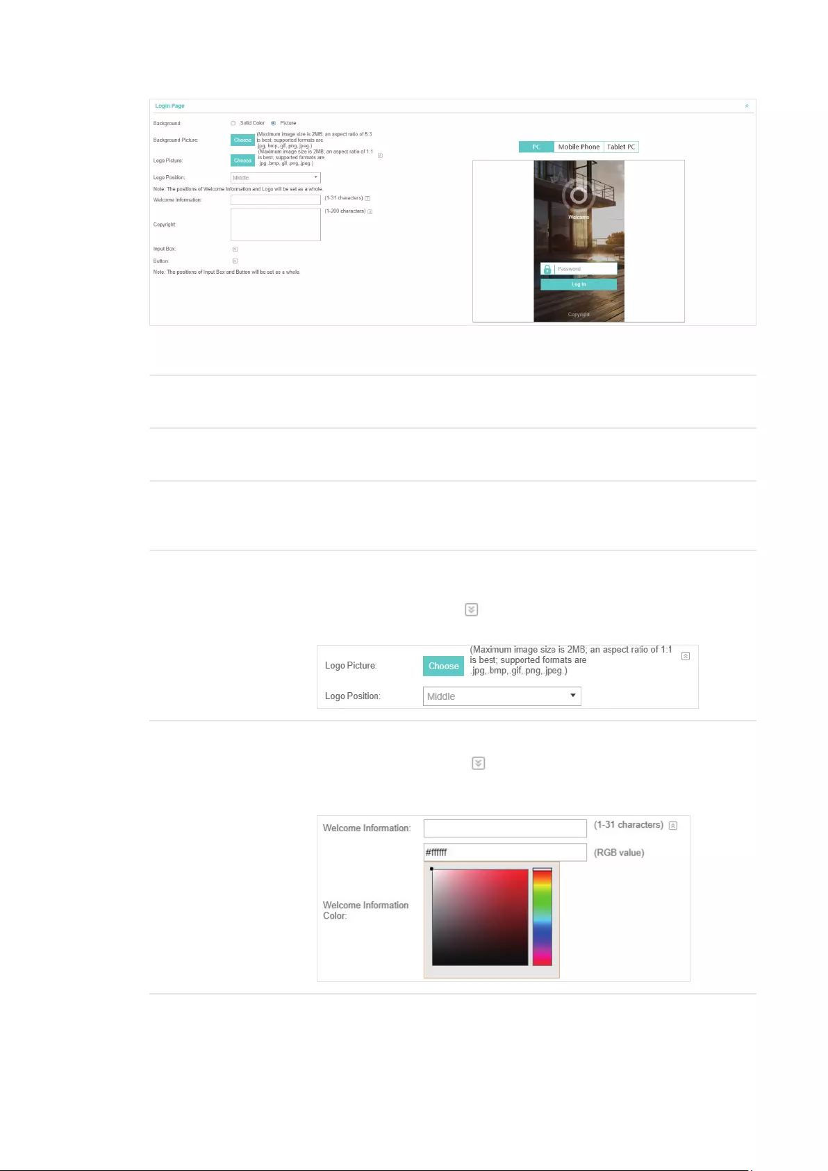
3. In the Login Page section, configure the login page for the Portal.
Congure the following parameters:
Background Select the background type. Two types are supported: Solid Color and
Picture.
Background Color If Solid Color is selected, configure your desired background color through
the color picker or by entering the RGB value manually.
Background Picture If Picture is selected, click the Choose button and select a picture from
your PC. Drag and scale the clipping region to edit the picture and click
Confirm.
Logo Picture Click the Choose button and select a picture from your PC. Drag and scale
the clipping region to edit the picture and click Confirm.
In addtion, you can click and configure the logo position. The options
include Middle, Upper and Lower.

38
Welcome Information Specify the welcome information.
In addtion, you can click and select your desired text color for the
welcome information through the color picker or by entering the RGB value
manually.
Copyright Specify the copyright information.
In addtion, you can click and select your desired text color for Copyright
information through the color picker or by entering the RGB value manually.

39
Button Click and configure the button.
Button Position: Set the position of the login button. The options include
Middle, Upper and Lower.
Button Color: Select your desired login button color through the color
picker or by entering the RGB value manually.
Button Text Color: Select your desired text color for the button through the
color picker or by entering the RGB value manually.
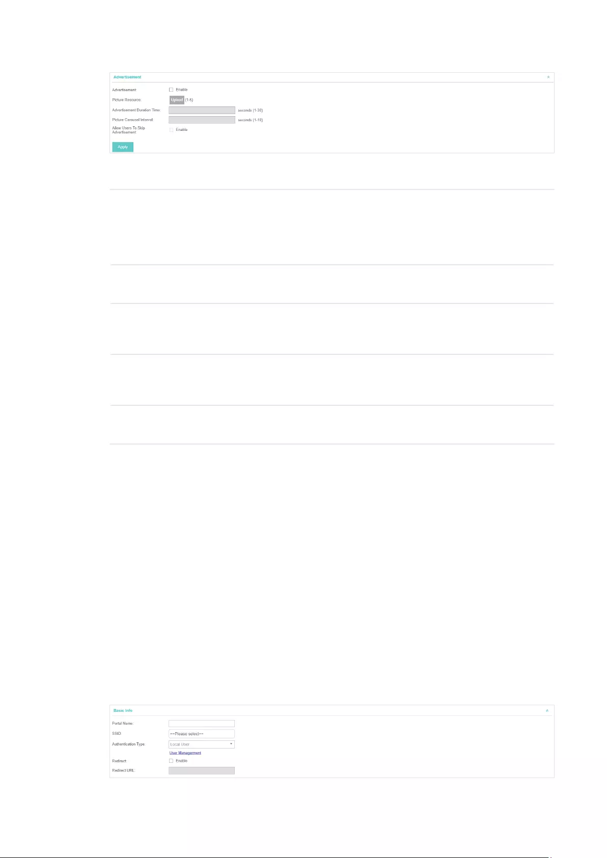
4. In the Advertisement section, select whether display advertisement pictures for users and
configure the related parameters.
Congure the following parameters:
Advertisement Specify whether to enable the Advertisement feature. With this feature
enabled, you can add advertisement pictures on the authentication page.
These advertisement pictures will be displayed before the login page
appears. You can also allow users to skip the advertisement by enabling
Allow to Skip Advertisement.
Picture Resource Upload advertisement pictures. When several pictures are added, they will
be played in a loop.
Advertisement
Duration Time
Specify how long the advertisement will be displayed for. For this duration,
the pictures will be played in a loop. If the duration time is not enough for all
the pictures, the rest will not be displayed.

40
Picture Careusel
Interval
Specify the picture carousel interval. For example, if this value is set as 5
seconds, the first picture will be displayed for 5 seconds, followed by the
second picture for 5 seconds, and so on.
Allow Users To Skip
Advertisement
Specify whether to enable this feature. With this feature enabled, the user
can click the Skip button to skip the advertisement.
5. Click Apply.
3.3.2 Simple Password
With Simple Password configured, clients are required to enter the correct password to pass the
authentication.
Follow the steps below to configure No Simple Password Portal:
1. Go to Wireless Settings > Basic Wireless Settings and create an SSID for the Portal.
2. Go back to the Portal configruation page. In the Basic Info section, complete the basic settings
for the portal authentication.
Congure the following parameters:
Portal Name Specify a name for the Portal.
SSID Select an SSID for the Portal.
Authentication Type Select Simple Password.
Password Set the password for authentication.
Authentication
Timeout
The client’s authentication will expire after the time period you set and
the client needs to log in the web authentication page again to access the
network.
Options include 1 Hour, 8 Hours, 24 Hours, 7 Days, Custom. Custom allows
you to define the time in days, hours, and minutes. The default value is one
hour.
Redirect If you enable this function, the portal will redirect the newly authenticated
clients to the configured URL.
Redirect URL If the Redirect function above is enabled, enter the URL that a newly
authenticated client will be redirected to.
3. In the Login Page section, configure the login page for the Portal.
41
Congure the following parameters:
Background Select the background type. Two types are supported: Solid Color and
Picture.
Background Color If Solid Color is selected, configure your desired background color through
the color picker or by entering the RGB value manually.
Background Picture If Picture is selected, click the Choose button and select a picture from
your PC. Drag and scale the clipping region to edit the picture and click
Confirm.
Logo Picture Click the Choose button and select a picture from your PC. Drag and scale
the clipping region to edit the picture and click Confirm.
In addtion, you can click and configure the logo position. The options
include Middle, Upper and Lower.
Welcome Information Specify the welcome information.
In addtion, you can click and select your desired text color for the
welcome information through the color picker or by entering the RGB value
manually.

42
Copyright Specify the copyright information.
In addtion, you can click and select your desired text color for Copyright
information through the color picker or by entering the RGB value manually.
Button Click and configure the button.
Button Position: Set the position of the login button. The options include
Middle, Upper and Lower.
Button Color: Select your desired login button color through the color
picker or by entering the RGB value manually.
Button Text Color: Select your desired text color for the button through the
color picker or by entering the RGB value manually.
4. In the Advertisement section, select whether display advertisement pictures for users and
configure the related parameters.
43
Congure the following parameters:
Advertisement Specify whether to enable the Advertisement feature. With this feature
enabled, you can add advertisement pictures on the authentication page.
These advertisement pictures will be displayed before the login page
appears. You can also allow users to skip the advertisement by enabling
Allow to Skip Advertisement.
Picture Resource Upload advertisement pictures. When several pictures are added, they will
be played in a loop.
Advertisement
Duration Time
Specify how long the advertisement will be displayed for. For this duration,
the pictures will be played in a loop. If the duration time is not enough for all
the pictures, the rest will not be displayed.
Picture Careusel
Interval
Specify the picture carousel interval. For example, if this value is set as 5
seconds, the first picture will be displayed for 5 seconds, followed by the
second picture for 5 seconds, and so on.
Allow Users To Skip
Advertisement
Specify whether to enable this feature. With this feature enabled, the user
can click the Skip button to skip the advertisement.
5. Click Apply.
3.3.3 Local User
With Local User configured, clients are required to enter the correct username and password of
the login account to pass the authentication. You can create multiple accounts and assign different
accounts for different users.
Configure Local User Portal
Follow the steps below to configure Local User Portal:
1. Go to Wireless Settings > Basic Wireless Settings and create an SSID for the Portal.
2. Go back to the Portal configruation page. In the Basic Info section, complete the basic settings
for the portal authentication.
44
Congure the following parameters:
Portal Name Specify a name for the Portal.
SSID Select an SSID for the Portal.
Authentication Type Select Local User.
User Management You can click this button to configure user accounts for authentication later.
Please refer to Create Local User Accounts.
Redirect If you enable this function, the portal will redirect the newly authenticated
clients to the configured URL.
Redirect URL If the Redirect function above is enabled, enter the URL that a newly
authenticated client will be redirected to.
3. In the Login Page section, configure the login page for the Portal.
Congure the following parameters:
Background Select the background type. Two types are supported: Solid Color and
Picture.
Background Color If Solid Color is selected, configure your desired background color through
the color picker or by entering the RGB value manually.
Background Picture If Picture is selected, click the Choose button and select a picture from
your PC. Drag and scale the clipping region to edit the picture and click
Confirm.
Logo Picture Click the Choose button and select a picture from your PC. Drag and scale
the clipping region to edit the picture and click Confirm.
In addtion, you can click and configure the logo position. The options
include Middle, Upper and Lower.

45
Welcome Information Specify the welcome information.
In addtion, you can click and select your desired text color for the
welcome information through the color picker or by entering the RGB value
manually.
Copyright Specify the copyright information.
In addtion, you can click and select your desired text color for Copyright
information through the color picker or by entering the RGB value manually.

46
Button Click and configure the button.
Button Position: Set the position of the login button. The options include
Middle, Upper and Lower.
Button Color: Select your desired login button color through the color
picker or by entering the RGB value manually.
Button Text Color: Select your desired text color for the button through the
color picker or by entering the RGB value manually.
4. In the Advertisement section, select whether display advertisement pictures for users and
configure the related parameters.
Congure the following parameters:
Advertisement Specify whether to enable the Advertisement feature. With this feature
enabled, you can add advertisement pictures on the authentication page.
These advertisement pictures will be displayed before the login page
appears. You can also allow users to skip the advertisement by enabling
Allow to Skip Advertisement.
Picture Resource Upload advertisement pictures. When several pictures are added, they will
be played in a loop.
Advertisement
Duration Time
Specify how long the advertisement will be displayed for. For this duration,
the pictures will be played in a loop. If the duration time is not enough for all
the pictures, the rest will not be displayed.

47
Picture Careusel
Interval
Specify the picture carousel interval. For example, if this value is set as 5
seconds, the first picture will be displayed for 5 seconds, followed by the
second picture for 5 seconds, and so on.
Allow Users To Skip
Advertisement
Specify whether to enable this feature. With this feature enabled, the user
can click the Skip button to skip the advertisement.
5. Click Apply.
Create Local User Accounts
Follow the steps below to create the user accounts for authentication:
1. In the Basic Info section on the portal configuration page, select the authentication type as Local
User and click User Management. The management page will appear. Go to the User page and
click .
2. The following window will pop up. Configure the required parameters and click Apply.

48
Congure the following parameters:
Username Specify the username. The username should not be the same as any
existing one.
Password Specify the password. Users will be required to enter the username and
password when they attempt to access the network.
Authentication
Timeout
Specify the authentication timeout for formal users. After the timeout, the
users need to log in at the web authentication page again to access the
network.
MAC Address Binding
Type
There are three types of MAC binding: No Binding, Static Binding and
Dynamic Binding.
Static Binding: Specify a MAC address for this user account. Then only the
user with the this MAC address can use the username and password to
pass the authentication.
Dynamic Binding: The MAC address of the first user that passes the
authentication will be bound. Then only this user can use the username and
password to pass the authentication.
Maximum Users Specify the maximum number of users able to use this account to pass the
authencitation. This option is available only when the MAC Address Binding
Type is set as No Binding.
Name Specify a name for identification.
Telephone Specify a telephone number for identification.
Rate Limit (Download) Select whether to enable download rate limit. With this option enabled, you
can specify the limit of download rate.
Rate Limit (Upload) Select whether to enable upload rate limit. With this option enabled, you
can specify the limit of upload rate.
Traffic Limit Select whether to enable traffic limit. With this option enabled, you can
specify the total traffic limit for the user. Once the limit is reached, the user
can no longer use this account to access the network.
3. In the same way, you can add more user accounts. The created user accounts will be displayed
in the list. Users can use the username and password of the account to pass the portal
authentication.
By default, the account Status is , which means that the user account is enabled and valid. You
can also click this icon to disable the user account. The icon will be changed to , which means
that the user account is disabled.

49
Additionally, you can click to backup all the user account information into a CSV le
or XLS le and save the le to your PC. If needed, you can click and select the le to
import the account information to the list.
Note:
Using Excel to open the CSV file may cause some numerical format changes, and the number may be
displayed incorrectly. If you use Excel to edit the CSV file, please set the cell format as text.
Manage the Guests
On the Guest page, you can view the information of clients that have passed the portal
authentication and manage the clients.
You can select an icon to execute the corresponding operation:
Disconnect client.
Extend the effective time.
Create Operator Accounts
Operator account can be used to remotely manage the Local User Portal and Voucher Portal. Other
users can visit the URL https://EAP Controller Host’s IP Address:8043/hotspot (For example:
https://192.168.0.64:8043/hotspot) and use the Operator account to enter the portal management
page.
Note:
The users who enter the portal management page by Operator account can only create local user accounts
and vouchers and manage the clients.
Follow the steps below to create Operator account.
1. Go to the Operator page.
2. Click and the following window will pop up.
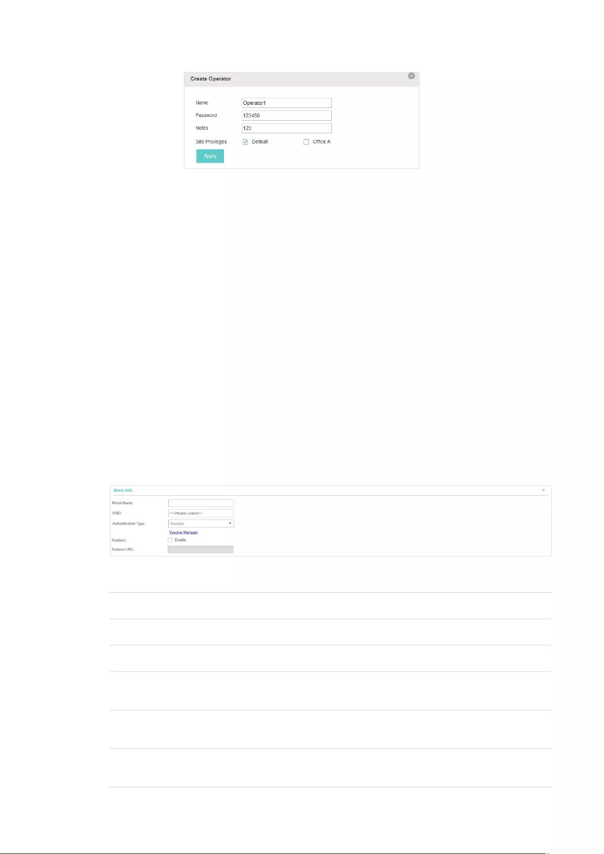
50
3. Specify the Name, Password and Notes of the Operator account.
4. Choose Site Privileges (more than one options can be chosen) for the Operator account.
5. Click Apply to create an Operator account. Then other users can use this account to enter the
hotspot management page.
3.3.4 Voucher
With Voucher configured, you can distribute the vouchers automatically generated by the EAP
Controller to the clients. Clients can use the vouchers to access the network.
Configure Voucher Portal
Follow the steps below to configure Voucher Portal:
1. Go to Wireless Settings > Basic Wireless Settings and create an SSID for the Portal.
2. Go back to the Portal configruation page. In the Basic Info section, complete the basic settings
for the portal authentication.
Congure the following parameters:
Portal Name Specify a name for the Portal.
SSID Select an SSID for the Portal.
Authentication Type Select Voucher.
User Management You can click this button to configure vouchers for authentication later.
Please refer to
Create Vouchers
.
Redirect If you enable this function, the portal will redirect the newly authenticated
clients to the configured URL.
Redirect URL If the Redirect function above is enabled, enter the URL that a newly
authenticated client will be redirected to.

51
3. In the Login Page section, configure the login page for the Portal.
Congure the following parameters:
Background Select the background type. Two types are supported: Solid Color and
Picture.
Background Color If Solid Color is selected, configure your desired background color through
the color picker or by entering the RGB value manually.
Background Picture If Picture is selected, click the Choose button and select a picture from
your PC. Drag and scale the clipping region to edit the picture and click
Confirm.
Logo Picture Click the Choose button and select a picture from your PC. Drag and scale
the clipping region to edit the picture and click Confirm.
In addtion, you can click and configure the logo position. The options
include Middle, Upper and Lower.
Welcome Information Specify the welcome information.
In addtion, you can click and select your desired text color for the
welcome information through the color picker or by entering the RGB value
manually.
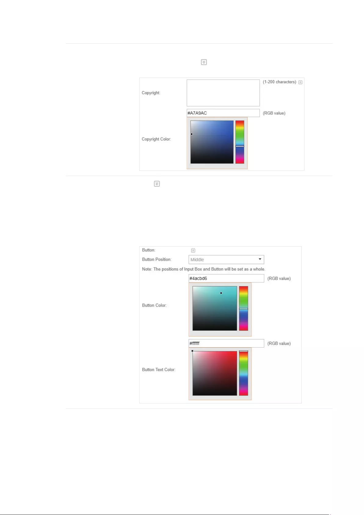
52
Copyright Specify the copyright information.
In addtion, you can click and select your desired text color for Copyright
information through the color picker or by entering the RGB value manually.
Button Click and configure the button.
Button Position: Set the position of the login button. The options include
Middle, Upper and Lower.
Button Color: Select your desired login button color through the color
picker or by entering the RGB value manually.
Button Text Color: Select your desired text color for the button through the
color picker or by entering the RGB value manually.
4. In the Advertisement section, select whether display advertisement pictures for users and
configure the related parameters.
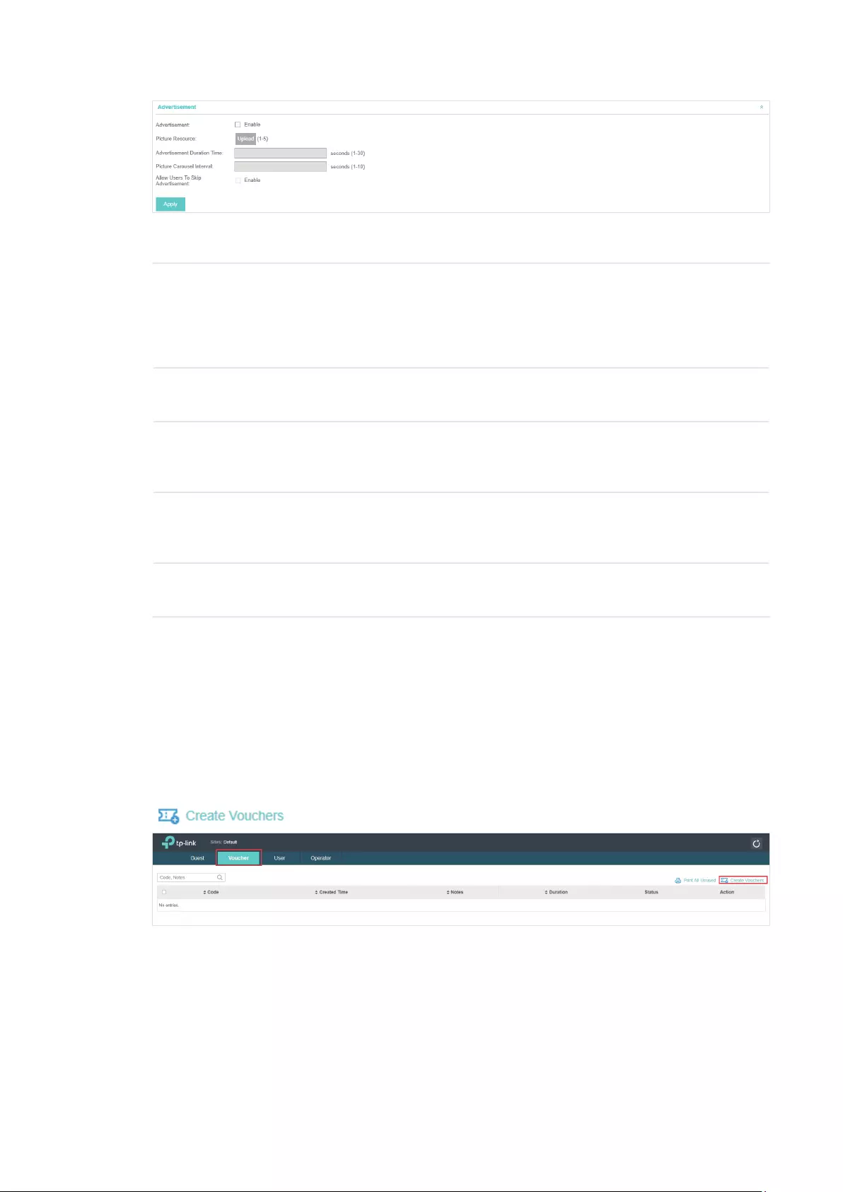
53
Congure the following parameters:
Advertisement Specify whether to enable the Advertisement feature. With this feature
enabled, you can add advertisement pictures on the authentication page.
These advertisement pictures will be displayed before the login page
appears. You can also allow users to skip the advertisement by enabling
Allow to Skip Advertisement.
Picture Resource Upload advertisement pictures. When several pictures are added, they will
be played in a loop.
Advertisement
Duration Time
Specify how long the advertisement will be displayed for. For this duration,
the pictures will be played in a loop. If the duration time is not enough for all
the pictures, the rest will not be displayed.
Picture Careusel
Interval
Specify the picture carousel interval. For example, if this value is set as 5
seconds, the first picture will be displayed for 5 seconds, followed by the
second picture for 5 seconds, and so on.
Allow Users To Skip
Advertisement
Specify whether to enable this feature. With this feature enabled, the user
can click the Skip button to skip the advertisement.
5. Click Apply.
Create Vouchers
Follow the steps below to create vouchers for authentication:
1. In the Basic Info section, select the authentication type as Voucher and click Voucher
Manager. The voucher management page will appear. Go to the Voucher page and click
.
2. The following window will pop up. Configure the required parameters and click Apply.
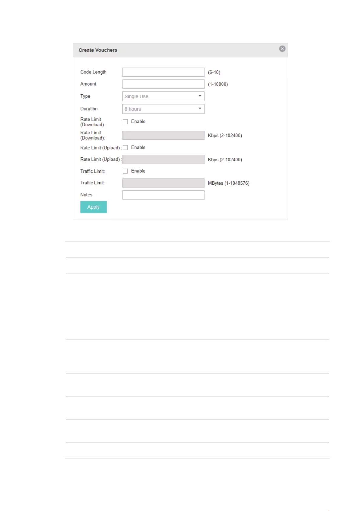
54
Congure the following parameters:
Code Length Specify the length of the voucher codes to be created.
Amount Enter the voucher amount to be generated.
Type Select Single Use or Multi Use.
Single Use means one voucher can only be distributed to one client. Multi Use
means one voucher can be distributed to several clients, who can use the
same voucher to access the network at the same time.
If you select Multi Use, enter the value of Max Users. When the number of
clients who are connected to the network with the same voucher reaches the
value, no more clients can use this voucher to access the network.
Duration Select the period of validity of the Voucher.
The options include 8 hours, 2 days and User-defined. The period of valid of
the voucher is reckoned from the time when it is used for the first time.
Rate Limit
(Download)
Select whether to enable download rate limit. With this option enabled, you
can specify the limit of download rate.
Rate Limit (Upload) Select whether to enable upload rate limit. With this option enabled, you can
specify the limit of upload rate.
Traffic Limit Specify the total traffic limit for one voucher. Once the limit is reached, the
client can no longer access the network using the voucher.
Notes Enter a description for the Voucher (optional).
3. The Vouchers will be generated and displayed on the page.
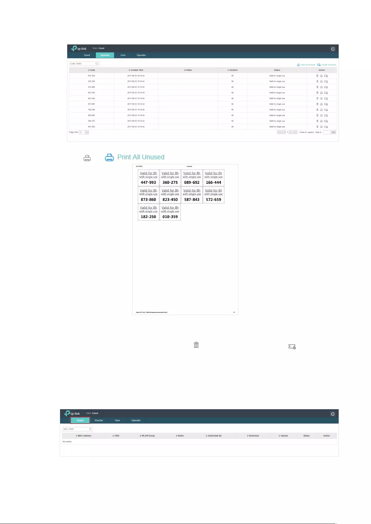
55
4. Click or to print and save the vouchers.
5. Distribute the vouchers to clients, and then they can use the codes to pass authentication.
6. When the vouchers are invalid, you can click to delete the Voucher or click to delete all of
them.
Manage the Guests
On the Guest page, you can view the information of clients that have passed the portal
authentication and manage the clients.
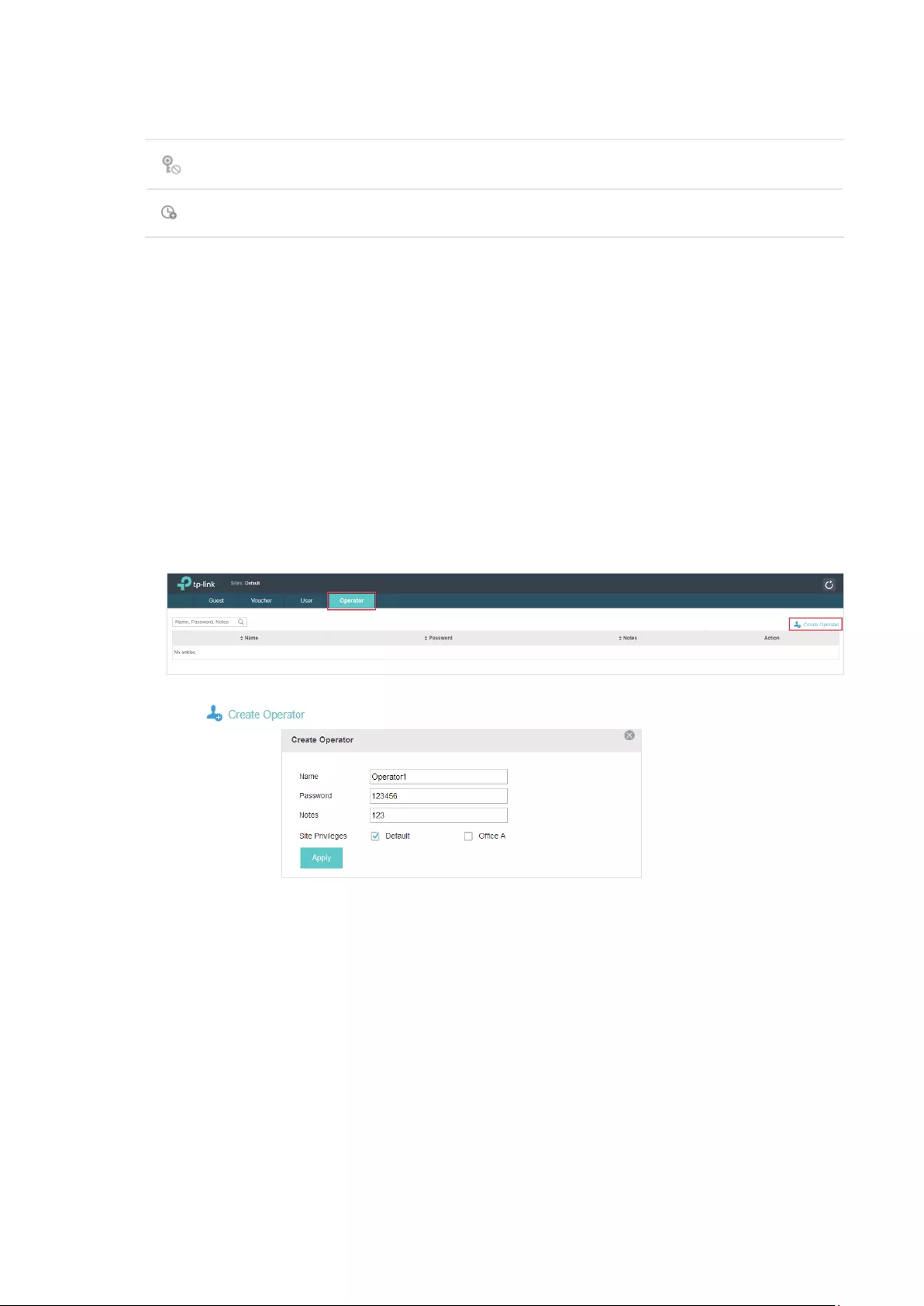
56
You can select an icon to execute the corresponding operation:
Restrict the client to access the network.
Extend the effective time.
Create Operator Accounts
Operator account can be used to remotely manage the Local User Portal and Voucher Portal. Other
users can visit the URL https://EAP Controller Host’s IP Address:8043/hotspot (For example:
https://192.168.0.64:8043/hotspot) and use the Operator account to enter the portal management
page.
Note:
The users who enter the portal management page by Operator account can only create local user accounts
and vouchers and manage the clients.
Follow the steps below to create Operator account.
1. Go to the Operator page.
2. Click and the following window will pop up.
3. Specify the Name, Password and Notes of the Operator account.
4. Choose Site Privileges (more than one options can be chosen) for the Operator account.
5. Click Apply to create an Operator account. Then other users can use this account to enter the
hotspot administrative system.

57
3.3.5 SMS
With SMS portal configured, client can get verification codes using their mobile phones and enter
the received codes to pass the authentication.
Follow the steps below to configure SMS Portal:
1. Go to www.twilio.com/try-twilio and get a Twilo account. Buy the Twilio service for SMS. Then get
the account information, including ACCOUNT SID, AUTH TOKEN and Phone number.
2. Go to Wireless Settings > Basic Wireless Settings and create an SSID for the Portal.
3. Go back to the Portal configruation page. In the Basic Info section, complete the basic settings
for the portal authentication.
Congure the following parameters:
Portal Name Specify a name for the Portal.
SSID Select an SSID for the Portal.
Authentication Type Select SMS.
Twilio SID Enter the Account SID for Twilio API Credentials.
Auth Token Enter the Authentication Token for Twilio API Credentials.
Phone Number Enter the phone number that is used to send verification messages to the
clients.
Maximum Users A telephone can get several codes via messages one by one, and different
clients can use different codes to pass the authentication. However, the
number of clients that are allowed to be authenticated using the same
telephone at the same time has a upper limit.
Specify the upper limit in this field.
Authentication
Timeout
The client’s authentication will expire after the time period you set and
the client needs to log in the web authentication page again to access the
network.
Options include 1 Hour, 8 Hours, 24 Hours, 7 Days, Custom. Custom allows
you to define the time in days, hours, and minutes. The default value is one
hour.

58
Preset Country Code Set the default country code that will be filled automatically on the
authentication page.
Redirect If you enable this function, the portal will redirect the newly authenticated
clients to the configured URL.
Redirect URL If the Redirect function above is enabled, enter the URL that a newly
authenticated client will be redirected to.
4. In the Login Page section, configure the login page for the Portal.
Congure the following parameters:
Background Select the background type. Two types are supported: Solid Color and
Picture.
Background Color If Solid Color is selected, configure your desired background color through
the color picker or by entering the RGB value manually.
Background Picture If Picture is selected, click the Choose button and select a picture from
your PC. Drag and scale the clipping region to edit the picture and click
Confirm.
Logo Picture Click the Choose button and select a picture from your PC. Drag and scale
the clipping region to edit the picture and click Confirm.
In addtion, you can click and configure the logo position. The options
include Middle, Upper and Lower.

59
Welcome Information Specify the welcome information.
In addtion, you can click and select your desired text color for the
welcome information through the color picker or by entering the RGB value
manually.
Copyright Specify the copyright information.
In addtion, you can click and select your desired text color for Copyright
information through the color picker or by entering the RGB value manually.

60
Button Click and configure the button.
Button Position: Set the position of the login button. The options include
Middle, Upper and Lower.
Button Color: Select your desired login button color through the color
picker or by entering the RGB value manually.
Button Text Color: Select your desired text color for the button through the
color picker or by entering the RGB value manually.
5. In the Advertisement section, select whether display advertisement pictures for users and
configure the related parameters.
Congure the following parameters:
Advertisement Specify whether to enable the Advertisement feature. With this feature
enabled, you can add advertisement pictures on the authentication page.
These advertisement pictures will be displayed before the login page
appears. You can also allow users to skip the advertisement by enabling
Allow to Skip Advertisement.
Picture Resource Upload advertisement pictures. When several pictures are added, they will
be played in a loop.
Advertisement
Duration Time
Specify how long the advertisement will be displayed for. For this duration,
the pictures will be played in a loop. If the duration time is not enough for all
the pictures, the rest will not be displayed.
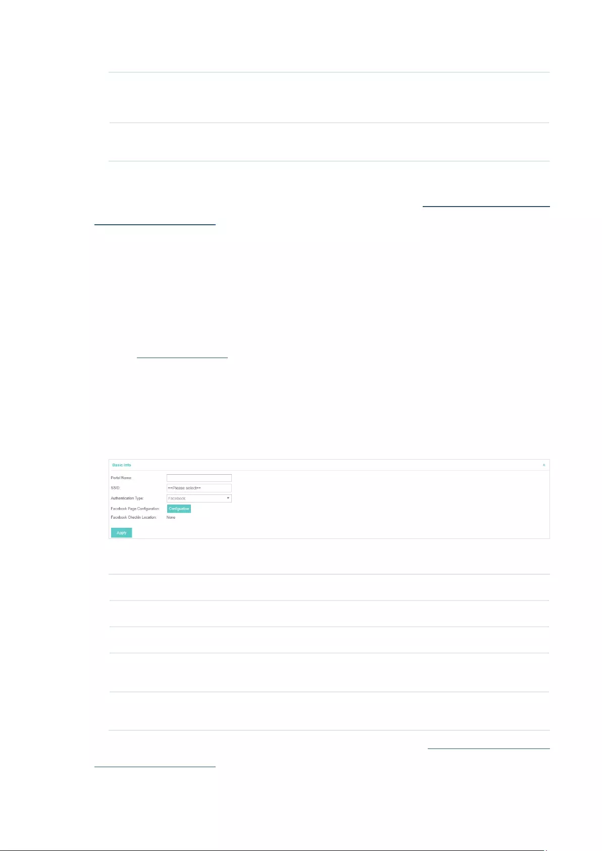
61
Picture Careusel
Interval
Specify the picture carousel interval. For example, if this value is set as 5
seconds, the first picture will be displayed for 5 seconds, followed by the
second picture for 5 seconds, and so on.
Allow Users To Skip
Advertisement
Specify whether to enable this feature. With this feature enabled, the user
can click the Skip button to skip the advertisement.
6. Click Apply.
For more details about how to configure SMS Portal, you can go to http://www.tp-link.com/en/
configuration-guides.html and download the configuration guide for SMS Portal.
3.3.6 Facebook
With Facebook Portal configured, when clients connect to your Wi-Fi, they will be
redirected to your Facebook page. To access the internet, clients need to pass the
authentication on the page.
Follow the steps below to configure Facebook Portal:
1. Go to www.facebook.com and get a Facebook account. Create your Facebook page according
to your needs.
2. Go to Wireless Settings > Basic Wireless Settings and create an SSID for the Portal.
3. Go back to the Portal configruation page. In the Basic Info section, complete the settings for the
portal authentication.
Congure the following parameters:
Portal Name Specify a name for the Portal.
SSID Select an SSID for the Portal.
Authentication Type Select Facebook.
Facebook Page
Configuration
Click this button to specify the Facebook Page.
Facebook Checkin
Location
If the Facebook page is successfully got by the EAP Controller, the name of
the Facebook page will be displayed here.
For more details about how to configure Facebook Portal, you can go to http://www.tp-link.com/en/
configuration-guides.html and download the configuration guide for Facebook Portal.
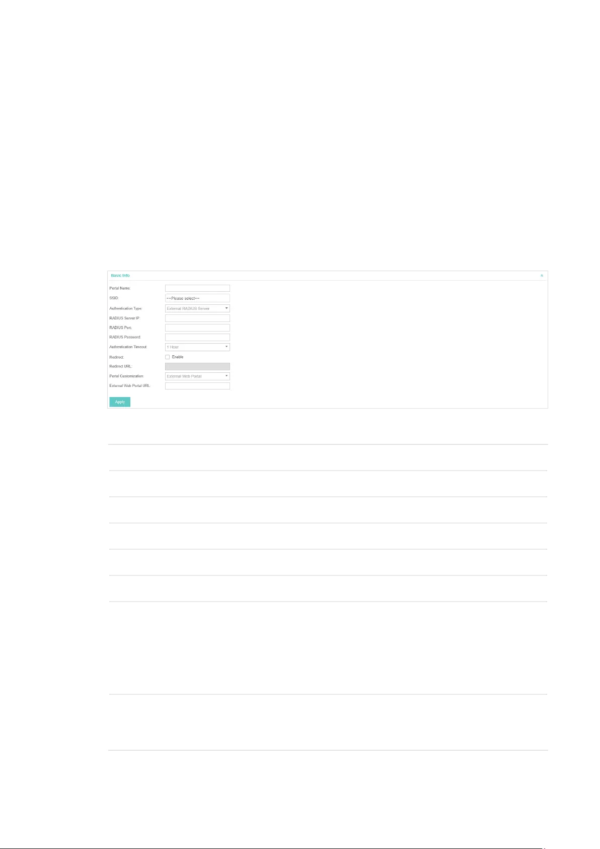
62
3.3.7 External RADIUS Server
If you have a RADIUS server, you can configure External RADIUS Server Portal. With this type of
portal, you can get two types of portal customization: Local Web Portal and External Web Portal.
The authentication login page of Local Web Portal is provided by the built-in portal server of the
EAP. The External Web Portal is provided by external portal server.
Follow the steps below to configure External RADIUS Server Portal:
1. Go to Wireless Settings > Basic Wireless Settings and create an SSID for the Portal.
2. Go back to the Portal configruation page. In the Basic Info section, complete the basic settings
for the portal authentication.
Congure the following parameters:
Portal Name Specify a name for the Portal.
SSID Select an SSID for the Portal.
Authentication Type Select Simple Password.
RADIUS Server IP Enter the IP address of the RADIUS server.
RADIUS Port Enter the port number you have set on the RADIUS server.
RADIUS Password Enter the password you have set on the RADIUS Server.
Authentication
Timeout
The client’s authentication will expire after the time period you set and
the client needs to log in the web authentication page again to access the
network.
Options include 1 Hour, 8 Hours, 24 Hours, 7 Days, Custom. Custom allows
you to define the time in days, hours, and minutes. The default value is one
hour.
Redirect If you enable this function, the portal will redirect the newly authenticated
clients to the configured URL.
Disabled by default.
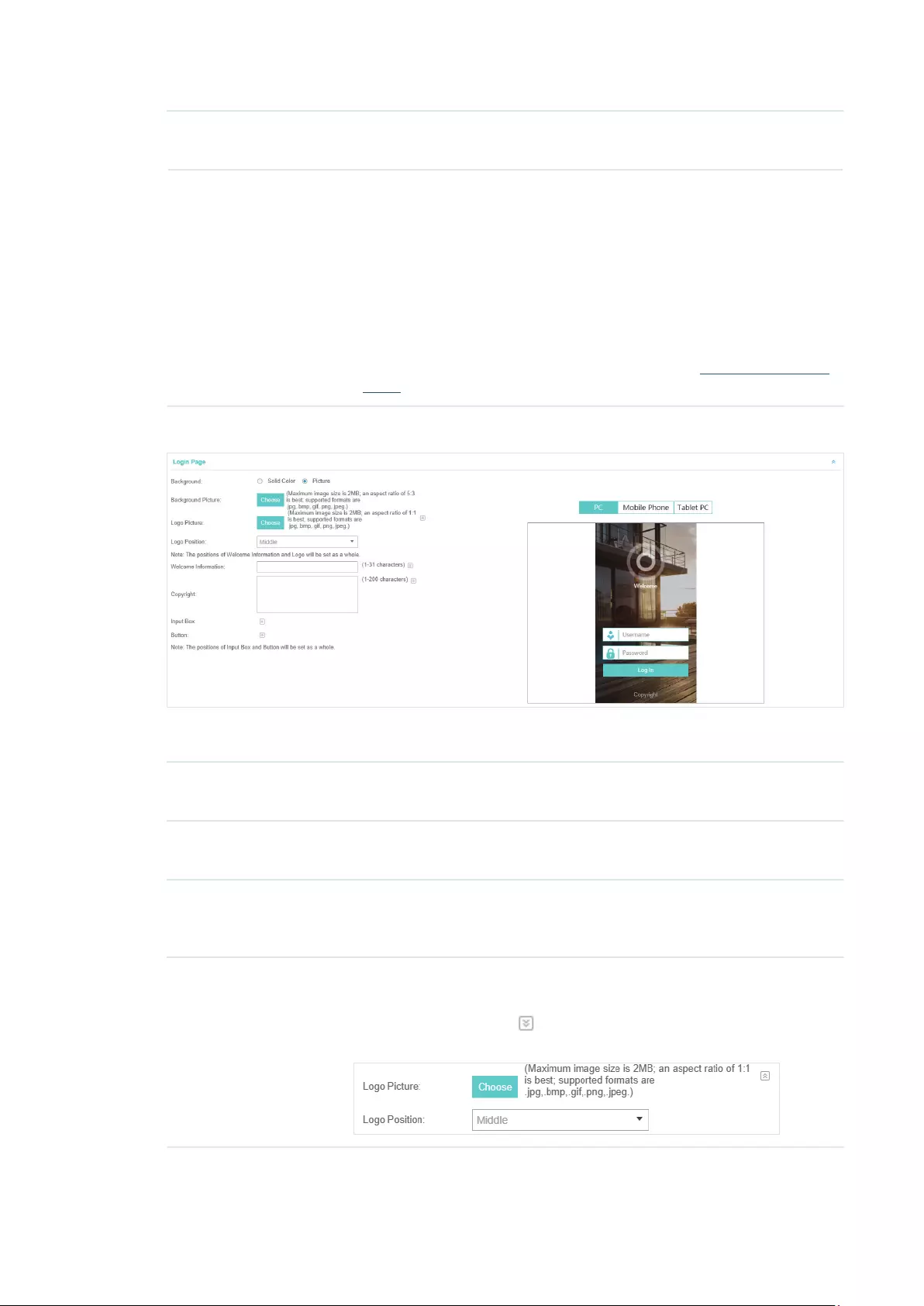
63
Redirect URL If the Redirect function above is enabled, enter the URL that a newly
authenticated client will be redirected to.
Portal Customization Select Local Web Portal or External Web Portal.
Local Web Portal: If this option is selected, refer to step 4 to configure the
login page and step 5 to configure the advertisement.
External Web Portal: If this option is selected, follow the steps below.
1. Configure the external RADIUS server.
2. Enter the authentication login page’s URL provided by the external portal
server in the External Web Portal URL field.
3. Put the external web portal server to a whitelist of Free Authentication
Policy, otherwise clients cannot access it before authenticated.
4. Local Web Portal is configured, configure the login page for the Portal in the Login Page section.
Congure the following parameters:
Background Select the background type. Two types are supported: Solid Color and
Picture.
Background Color If Solid Color is selected, configure your desired background color through
the color picker or by entering the RGB value manually.
Background Picture If Picture is selected, click the Choose button and select a picture from
your PC. Drag and scale the clipping region to edit the picture and click
Confirm.
Logo Picture Click the Choose button and select a picture from your PC. Drag and scale
the clipping region to edit the picture and click Confirm.
In addtion, you can click and configure the logo position. The options
include Middle, Upper and Lower.
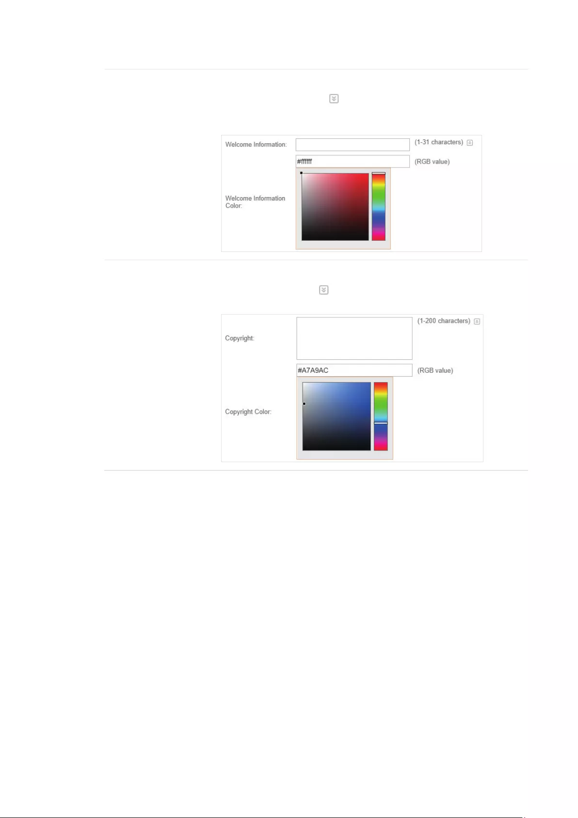
64
Welcome Information Specify the welcome information.
In addtion, you can click and select your desired text color for the
welcome information through the color picker or by entering the RGB value
manually.
Copyright Specify the copyright information.
In addtion, you can click and select your desired text color for Copyright
information through the color picker or by entering the RGB value manually.
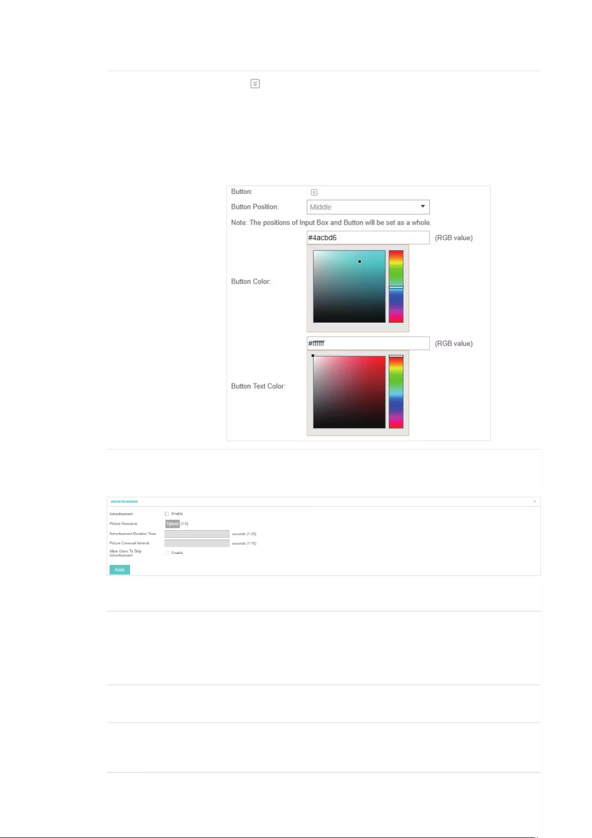
65
Button Click and configure the button.
Button Position: Set the position of the login button. The options include
Middle, Upper and Lower.
Button Color: Select your desired login button color through the color
picker or by entering the RGB value manually.
Button Text Color: Select your desired text color for the button through the
color picker or by entering the RGB value manually.
5. If Local Web Portal is configured, select whether display advertisement pictures for users and
configure the related parameters in the Advertisement section, .
Congure the following parameters:
Advertisement Specify whether to enable the Advertisement feature. With this feature
enabled, you can add advertisement pictures on the authentication page.
These advertisement pictures will be displayed before the login page
appears. You can also allow users to skip the advertisement by enabling
Allow to Skip Advertisement.
Picture Resource Upload advertisement pictures. When several pictures are added, they will
be played in a loop.
Advertisement
Duration Time
Specify how long the advertisement will be displayed for. For this duration,
the pictures will be played in a loop. If the duration time is not enough for all
the pictures, the rest will not be displayed.
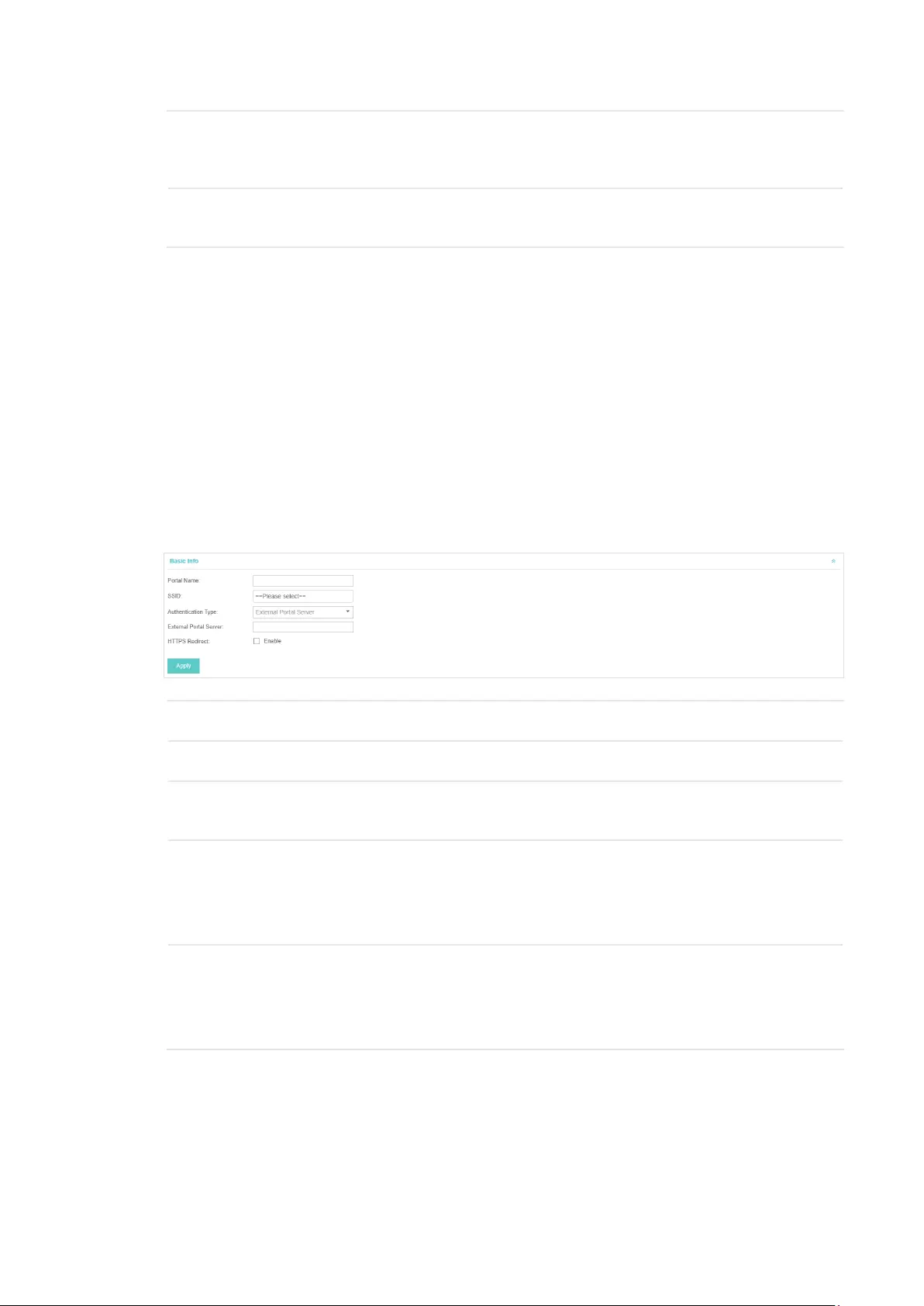
66
Picture Careusel
Interval
Specify the picture carousel interval. For example, if this value is set as 5
seconds, the first picture will be displayed for 5 seconds, followed by the
second picture for 5 seconds, and so on.
Allow Users To Skip
Advertisement
Specify whether to enable this feature. With this feature enabled, the user
can click the Skip button to skip the advertisement.
6. Click Apply.
3.3.8 External Portal Server
The option of External Portal Server is designed for the developers. They can customize their
own authentication type according to the interface provided by EAP Controller, e.g. message
authentication and WeChat authentication etc.
1. Go to Wireless Settings > Basic Wireless Settings and create an SSID for the Portal.
2. Go back to the Portal configruation page. In the Basic Info section, complete the settings for the
portal authentication.
Portal Name Specify a name for the Portal.
SSID Select an SSID for the Portal.
Authentication
Type
Select External Portal Server.
External Portal
Server
Enter the complete authentication URL that redirect to an external portal
server, for example:
http://192.168.0.147:8880/portal/index.php or http://192.168.0.147/portal/
index.html
HTTPS Redirect With this function enabled, the unauthorized clients will be redirected to the
Portal page when they are trying to browse HTTPS websites.
With this function disabled, the unauthorized clients cannot browse HTTPS
websites or be redirected to the Portal page.
3. Click Apply.
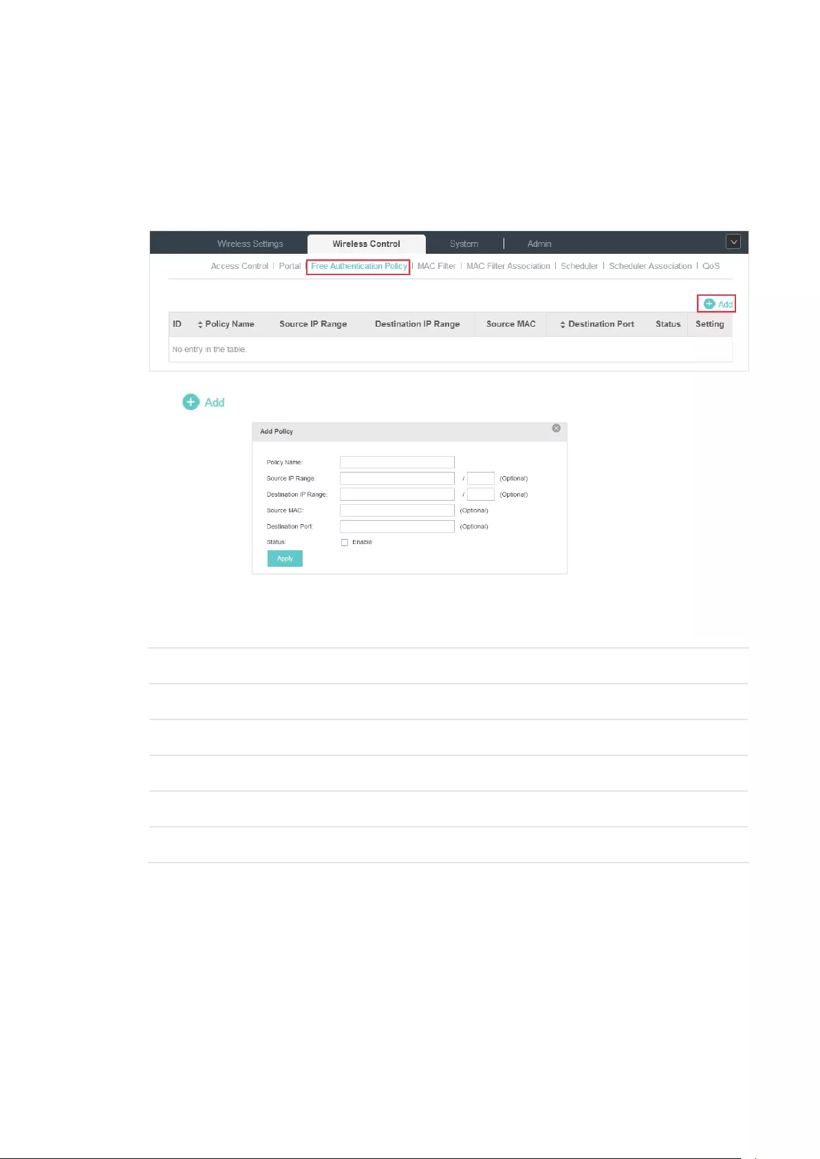
67
3.4 Free Authentication Policy
Free Authentication Policy allows some specified clients to access the network resources without
authentication. Follow the steps below to add free authentication policy.
1. Go to Wireless Control > Free Authentication Policy.
2. Click and the following window will pop up.
3. Configure the following parameters. When all conditions are met, the client can access the
network without authentication.
Policy Name Specify a name for the policy.
Source IP Range Set the Source IP Range with the subnet and mask length of the clients.
Destination IP Range Set the Destination IP Range with the subnet and mask length of the server.
Source MAC Set the MAC address of cilent.
Destination Port Enter the port the service uses.
Status Check the box to enable the policy.
4. Click Apply and the policy is successfully added.
3.5 MAC Filter
MAC filter can be used to allow or block the listed clients to access the network. Thereby it can
effectively control client’s access to the wireless network.
Follow the steps below to configure MAC Filter.
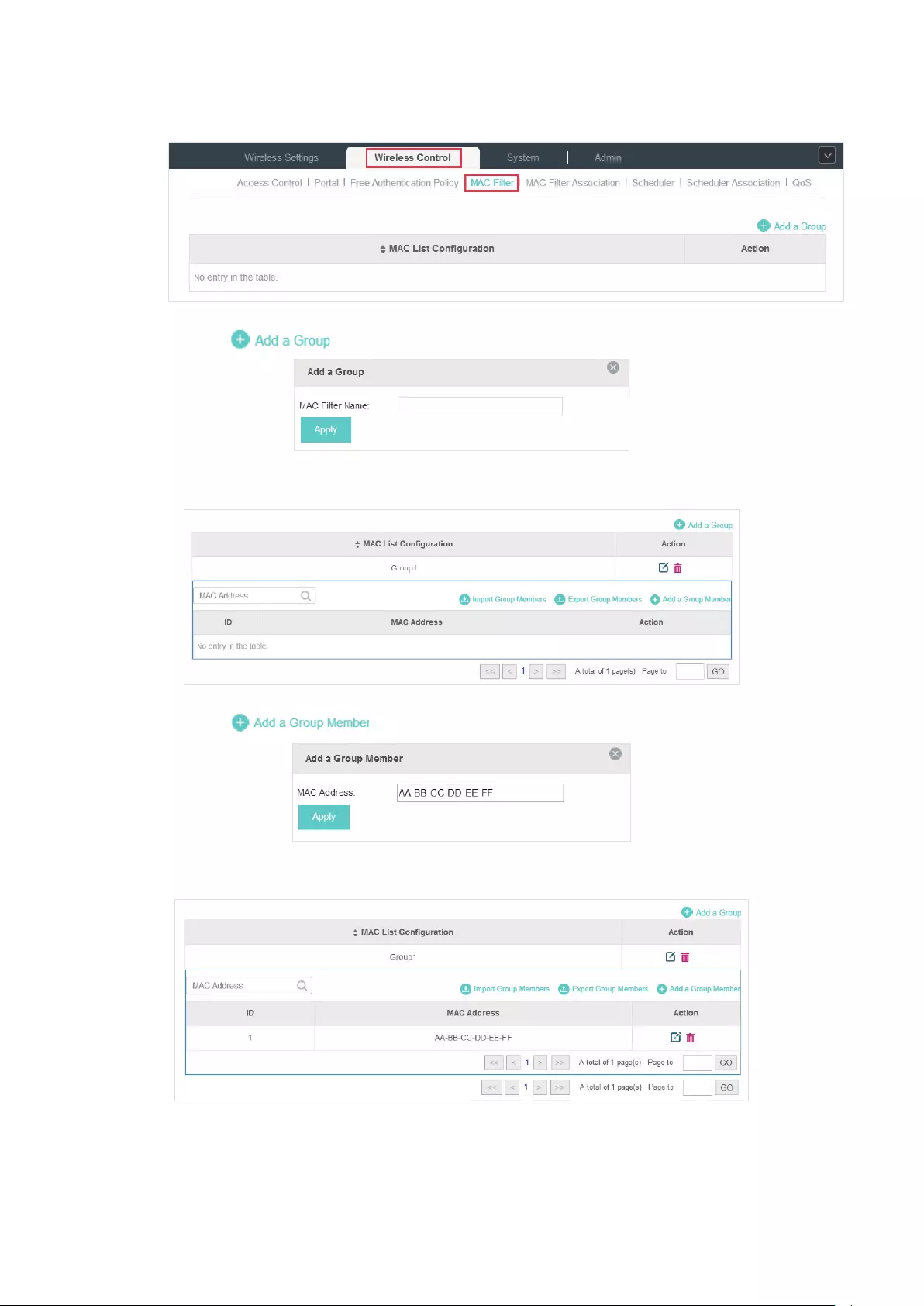
68
1. Go to Wireless Control > MAC Filter to add MAC Filter group and group members.
1 ) Click and specify a name for the group.
2 ) Click Apply and the group will be successfully added as shown below.
3 ) Click and enter a MAC address in the format as shown below.
4 ) Click Apply to add the MAC address into the MAC lter group.
2. You can add more groups or members according to your need.

69
Note:
You can click to export the group members to a excel file and save the file on your PC. If
needed, you can also click to import the group members to the EAP Controller.
3. Go to Wireless Control > MAC Filter Association to associate the added MAC Filter group with
SSID.
1 ) Check the box and click Apply to enable MAC Filtering function.
2 ) Select a band frequency (2.4GHz or 5GHz) and a WLAN group.
3 ) In the MAC Filter Name column of the specied SSID, select a MAC Filter group in the drop-
down list. Then select Allow/Deny in the Action column to allow/deny the clients in the MAC
Filter group to access the network.
4 ) Click Apply in the Setting column.
3.6 Scheduler
With the Scheduler, the EAPs or its’ wireless network can automatically turn on or off at the time you
set. For example, you can use this feature to schedule the radio to operate only during the office
working time in order to achieve security goals and reduce power consumption. You can also use
the Scheduler to make clients can only access the wireless network during the time period you set
in the day.
Follow the steps below to configure Scheduler.
1. Go to Wireless Control > Scheduler.

70
1 ) Click and specify a name for the prole.
2 ) Click Apply and the prole will be added.
3 ) Click and congure the parameters to specify a period of time.
4 ) Click Apply and the prole is successfully added in the list.
2. Go to Wireless Control > Scheduler Association.
1 ) Check the box to enable Scheduler function.
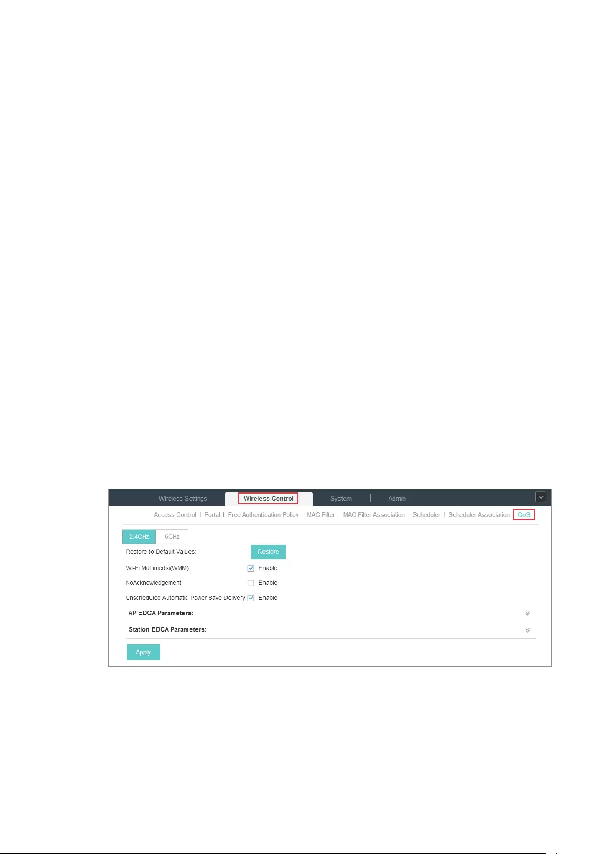
71
2 ) Select Associated with SSID (the prole will be applied to the specic SSID on all the EAPs)
or Associated with AP (the prole will be applied to all SSIDs on the specic EAP). Then click
Apply.
3 ) Select a band frequency (2.GHz or 5GHz) and a WLAN group.
4 ) In the Prole Name column of the specied SSID or AP, select a prole you added before in
the drop-down list. Select Radio O/Radio On to turn on or o the wireless network during
the time interval set for the prole.
5 ) Click Apply in the Setting column.
3.7 QoS
The EAP Controller software allows you to configure the quality of service (QoS) on the EAP device
for optimal throughput and performance when handling differentiated wireless traffic, such as
Voice-over-IP (VoIP), other types of audio, video, streaming media, and traditional IP data.
To configure QoS on the EAP device, you should set parameters on the transmission queues for
different types of wireless traffic and specify minimum and maximum wait times (through contention
windows) for transmission. In normal use, we recommend you keep the default values for the EAP
devices and station EDCA (Enhanced Distributed Channel Access).
Follow the steps below to configure QoS.
1. Go to Wireless Control > QoS.
2. Enable or disable the following features.

72
Wi-Fi Multimedia (WMM) By default enabled. With WMM enabled, the EAP devices have the QoS
function to guarantee the high priority of the transmission of audio and
video packets.
If 802.11n only mode is selected in 2.4GHz (or 802.11n only, 802.11ac
only, or 802.11 n/ac mixed mode in 5GHz), the WMM should be enabled. If
WMM is disabled, the 802.11n only mode cannot be selected in 2.4GHz (or
802.11n only, 802.11ac only, or 802.11 n/ac mixed mode in 5GHz).
NoAcknowledgement By default disabled. You can enable this function to specify that
the EAP devices should not acknowledge frames with QosNoAck.
NoAcknowledgement is recommended if VoIP phones access the network
through the EAP device.
Unscheduled Automatic
Power Save Delivery
By default enabled. As a power management method, it can greatly
improve the energy-saving capacity of clients.
3. Click AP EDCA Parameters and the following page will appear. AP EDCA parameters affect
traffic flowing from the EAP device to the client station. We recommend you use the defaults.
Queue Queue displays the transmission queue. By default, the priority from high to
low is Data 0, Data 1, Data 2, and Data 3. The priority may be changed if you
reset the EDCA parameters.
Data 0 (Voice)—Highest priority queue, minimum delay. Time-sensitive data
such as VoIP and streaming media are automatically sent to this queue.
Data 1 (Video)—High priority queue, minimum delay. Time-sensitive video
data is automatically sent to this queue.
Data 2 (Best Effort)—Medium priority queue, medium throughput and delay.
Most traditional IP data is sent to this queue.
Data 3 (Background)—Lowest priority queue, high throughput. Bulk data that
requires maximum throughput and is not time-sensitive is sent to this queue
(FTP data, for example).
Arbitration Inter-
Frame Space
A wait time for data frames. The wait time is measured in slots. Valid values
for Arbitration Inter-Frame Space are from 0 to 15.
Minimum Contention
Window
A list to the algorithm that determines the initial random backoff wait time
(window) for retry of a transmission.
This value can not be higher than the value for the Maximum Contention
Window.
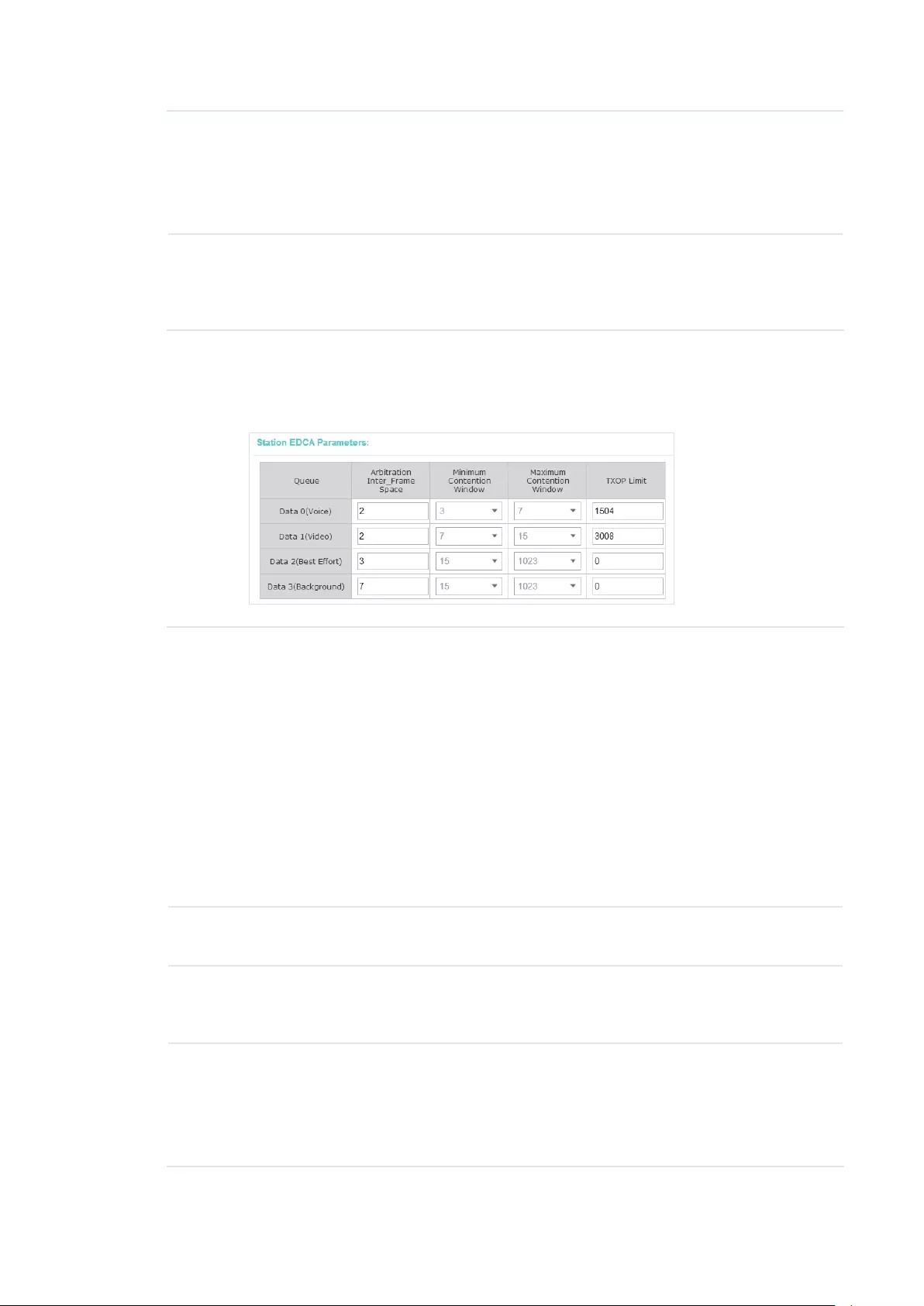
73
Maximum Contention
Window
The upper limit (in milliseconds) for the doubling of the random backoff value.
This doubling continues until either the data frame is sent or the Maximum
Contention Window size is reached.
This value must be higher than the value for the Minimum Contention
Window.
Maximum Burst Maximum Burst specifies the maximum burst length allowed for packet
bursts on the wireless network. A packet burst is a collection of multiple
frames transmitted without header information. The decreased overhead
results in higher throughput and better performance.
4. Click Station EDCA Parameters and the following page will appear. Station EDCA parameters
affect traffic flowing from the client station to the EAP device. We recommend you use the
defaults.
Queue Queue displays the transmission queue. By default, the priority from high to
low is Data 0, Data 1, Data 2, and Data 3. The priority may be changed if you
reset the EDCA parameters.
Data 0 (Voice)—Highest priority queue, minimum delay. Time-sensitive data
such as VoIP and streaming media are automatically sent to this queue.
Data 1 (Video)—High priority queue, minimum delay. Time-sensitive video
data is automatically sent to this queue.
Data 2 (Best Effort)—Medium priority queue, medium throughput and delay.
Most traditional IP data is sent to this queue.
Data 3 (Background)—Lowest priority queue, high throughput. Bulk data that
requires maximum throughput and is not time-sensitive is sent to this queue
(FTP data, for example).
Arbitration Inter-
Frame Space
A wait time for data frames. The wait time is measured in slots. Valid values
for Arbitration Inter-Frame Space are from 0 to 15.
Minimum Contention
Window
A list to the algorithm that determines the initial random backoff wait time
(window) for retry of a transmission. This value can not be higher than the
value for the Maximum Contention Window.
Maximum Contention
Window
The upper limit (in milliseconds) for the doubling of the random backoff value.
This doubling continues until either the data frame is sent or the Maximum
Contention Window size is reached.
This value must be higher than the value for the Minimum Contention
Window.
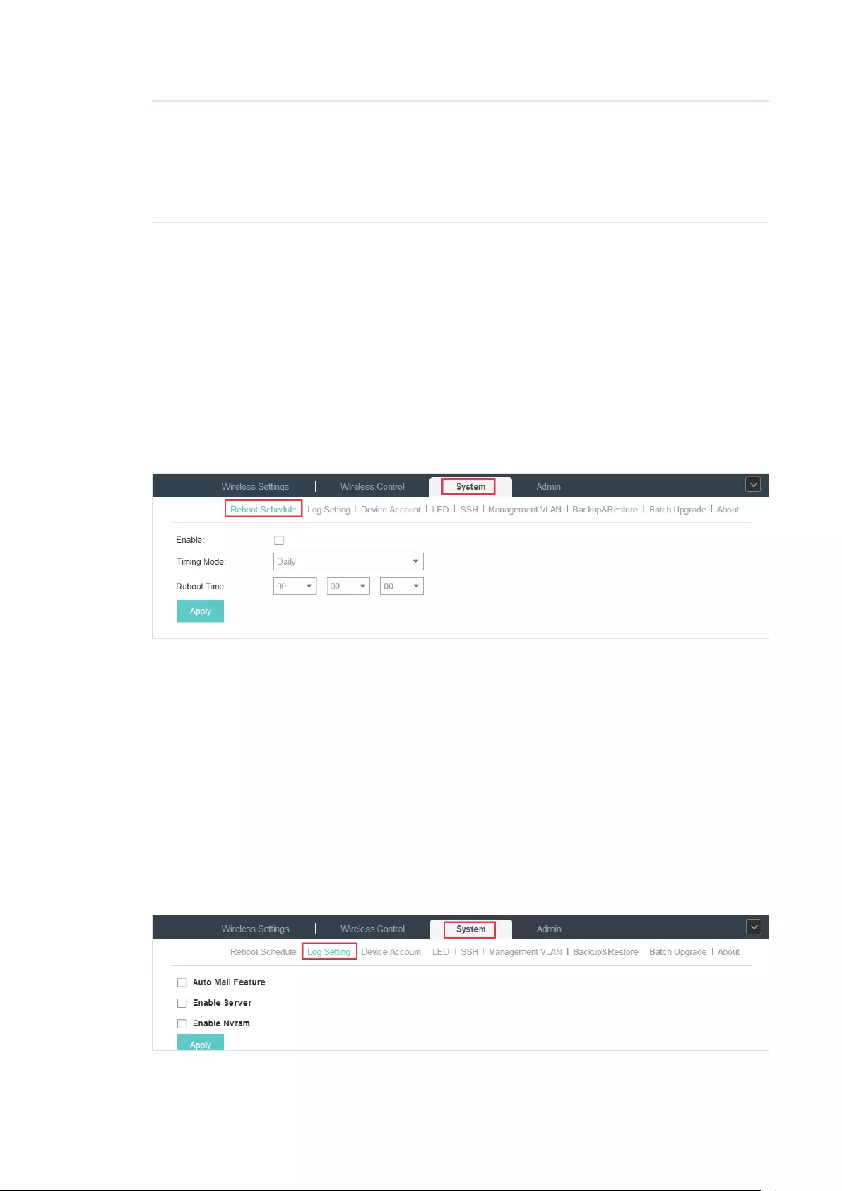
74
TXOP Limit The TXOP Limit is a station EDCA parameter and only applies to traffic
flowing from the client station to the EAP device. The Transmission
Opportunity (TXOP) is an interval of time, in milliseconds, when a WME client
station has the right to initiate transmissions onto the wireless medium (WM)
towards the EAP device. The valid values are multiples of 32 between 0 and
8192.
5. Click Apply.
3.8 System
3.8.1 Reboot Schedule
You can reboot all the EAPs in the network periodically as needed. Follow the steps below to
configure Reboot Schedule.
1. Go to System > Reboot Schedule.
2. Check the box to enable the function.
3. Choose Daily, Weekly or Monthly in the Timing Mode drop-down list and set a specific time to
reboot the EAPs.
4. Click Apply.
3.8.2 Log Setting
Follow the steps below to choose the way to receive system logs.
1. Go to System > Log Setting.

75
2. Check the box to choose the way to receive system logs (you can choose more than one) and
click Apply. Three ways are available: Auto Mail Feature, Server and Nvram.
Auto Mail Feature
If Auto Mail Feature is enabled, system logs will be sent to a specified mailbox. Check the box to
enable the feature and configure the parameters.
From Address Enter the sender’s E-mail address.
To Address Enter the receiver’s E-mail address.
SMTP Server Enter the IP address of the SMTP server.
Enable
Authentication
You can check the box to enable mail server authentication. Enter the sender’s
mail account name and password.
Time Mode Select Time Mode. System logs can be sent at specific time or time interval.
Fixation Time If you select Fixation Time, specify a fixed time to send the system log mails. For
example, 08:30 indicates that the mail will be sent at 8:30 am everyday.
Period Time If you select Period Time, specify a period time to regularly send the system log
mail. For example, 6 indicates that the mail will be sent every six hours.
Server
If Server is enabled, system logs will be sent to a server. You can enable the feature and enter its IP
address and port.

76
Nvram
Nvram (Non-volatile Random Access Memory) is a RAM that can still save data even if a device is
power off. All TP-Link EAPs are equipped with Nvram. With this option enabled, the Nvram feature
can help reserve the system logs when an EAP device is power off.
3.8.3 Device Account
When the EAP devices are adopted at the first time, their username and password will become the
same as those of the EAP Controller which are specified at Basic Configurations. You can specify a
new username and password for the adopted EAPs in batches.
Follow the steps below to change EAP devices’ username and password.
1. Go to System > Device Account.
2. Specify a new username and password for the EAP devices.
3. Click Apply.
Note::
The new account will be applied to EAP devices but not the EAP Controller. To change the EAP Controller’s us-
ername and password, please refer to User Account.
3.8.4 LED
Follow the steps below to turn on or off the LED lights of the EAPs.
1. Go to System > LED.
2. By default, the LED lights are on. You can check the box to change the light status.
3. Click Apply to save the configurations.
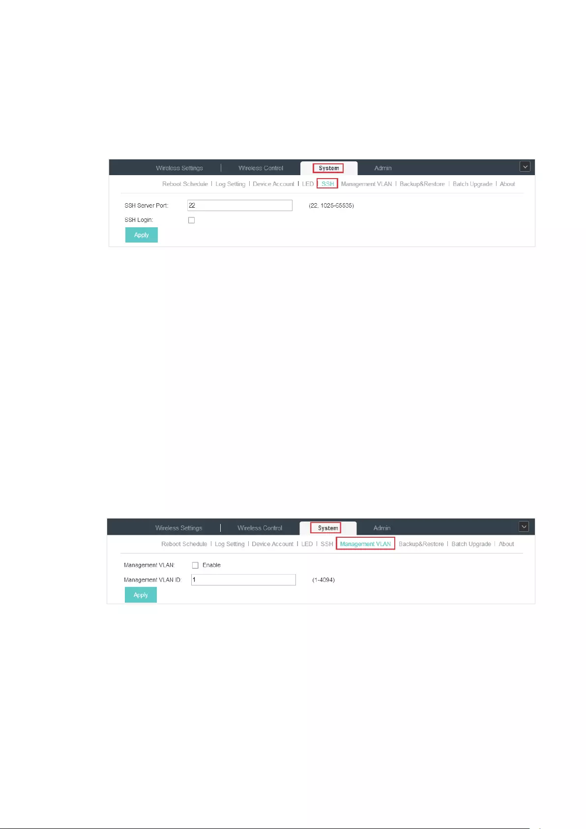
77
3.8.5 SSH
You can login to the EAP Controller via SSH. Deploy an SSH server on your network and follow the
steps below to configure SSH on the EAP Controller:
1. Go to System > SSH.
2. Enter the port number of the SSH server.
3. Check the box to enable SSH Login.
4. Click Apply.
3.8.6 Management VLAN
Management VLAN provides a safer way for you to manage the EAP. With Management VLAN
enabled, only the hosts in the management VLAN can manage the EAP. Since most hosts cannot
process VLAN TAGs, connect the management host to the network via a switch, and set up correct
VLAN settings for the switches on the network to ensure the communication between the host and
the EAP in the management VLAN.
Follow the steps below to configure Management VLAN.
1. Go to System > Management VLAN.
2. Check the box to enable Management VLAN.
3. Specify the Management VLAN ID.
4. Click Apply.

78
3.8.7 Backup&Restore
You can save the current configuration of the EAPs as a backup file and if necessary, and restore
the configuration using the backup file. We recommend you back up the settings before upgrading
the device.
Follow the steps below to backup and restore the configuration.
1. Go to System > Backup&Restore.
2. Click Backup and save the backup file.
3. If necessary, click Browse to locate and choose the backup file. Then click Restore to restore
the configuration.
3.8.8 Batch Upgrade
Follow the steps below to upgrade the EAP devices in batches according to their model.
1. Visit
http://www.tp-link.com/en/support/download/
to download the latest firmware file of the
corresponding model.
2. Go to System > Batch Upgrade.
3. Select the EAP model.
4. Click Browse to locate and choose the proper firmware file for the model.
5. Click Upgrade to upgrade the device.
6. After upgrading, the device will reboot automatically.
Note::
To avoid damage, please do not turn off the device while upgrading.

79
4 Congure the EAPs Separately
In addition to global configuration, you can configure the EAPs separately and the configuration
results will be applied to a specified EAP device.
To configure a specified EAP, please click the EAP’s name on the Access Points tab or click of
connected EAP on the map. Then you can view the EAP’s detailed information and configure the
EAP on the pop-up window.
This chapter includes the following contents:
·
View the Information of the EAP
·
View Clients Connecting to the EAP
·
Configure the EAP
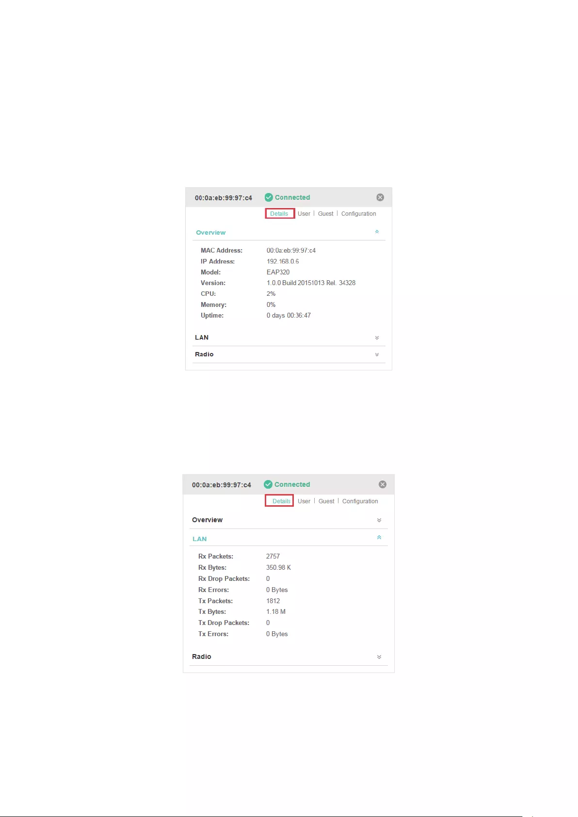
80
4.1 View the Information of the EAP
4.1.1 Overview
Click Overview to view the basic information including EAP’s MAC address (or name you set), IP
address, model, firmware version, the usage rate of CPU and Memory and uptime (indicates how
long the EAP has been running without interruption).
4.1.2 LAN
Click LAN to view the traffic information of the LAN port, including the total number of packets, the
total size of data, the total number of packets loss, and the total size of error data in the process of
receiving and transmitting data.

81
4.1.3 Radio
Click Radio to view the radio information including the frequency band, the wireless mode, the
channel width, the channel, and the transmitting power. At 2.4GHz, you can also view parameters of
receiving/transmitting data.
4.2 View Clients Connecting to the EAP
4.2.1 User
The User page displays the information of clients connecting to the SSID with Portal disabled,
including their MAC addresses and connected SSIDs. You can click the client’s MAC address to get
its connection history.
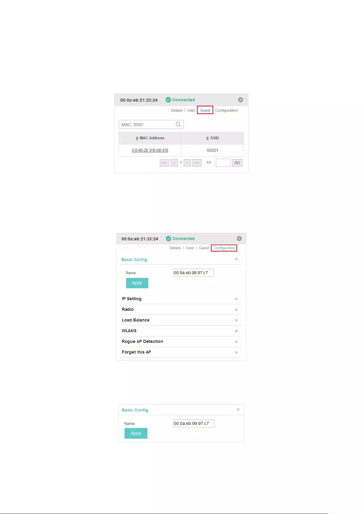
82
4.2.2 Guest
The Guest page displays the information of clients connecting to the SSID with Portal enabled,
including their MAC addresses and connected SSIDs. You can click the client’s MAC address to get
its connection history.
4.3 Configure the EAP
The Configuration page allows you to configure the EAP. All the configurations will only take effect
on this device.
4.3.1 Basic Config
Here you can change the name of the EAP.
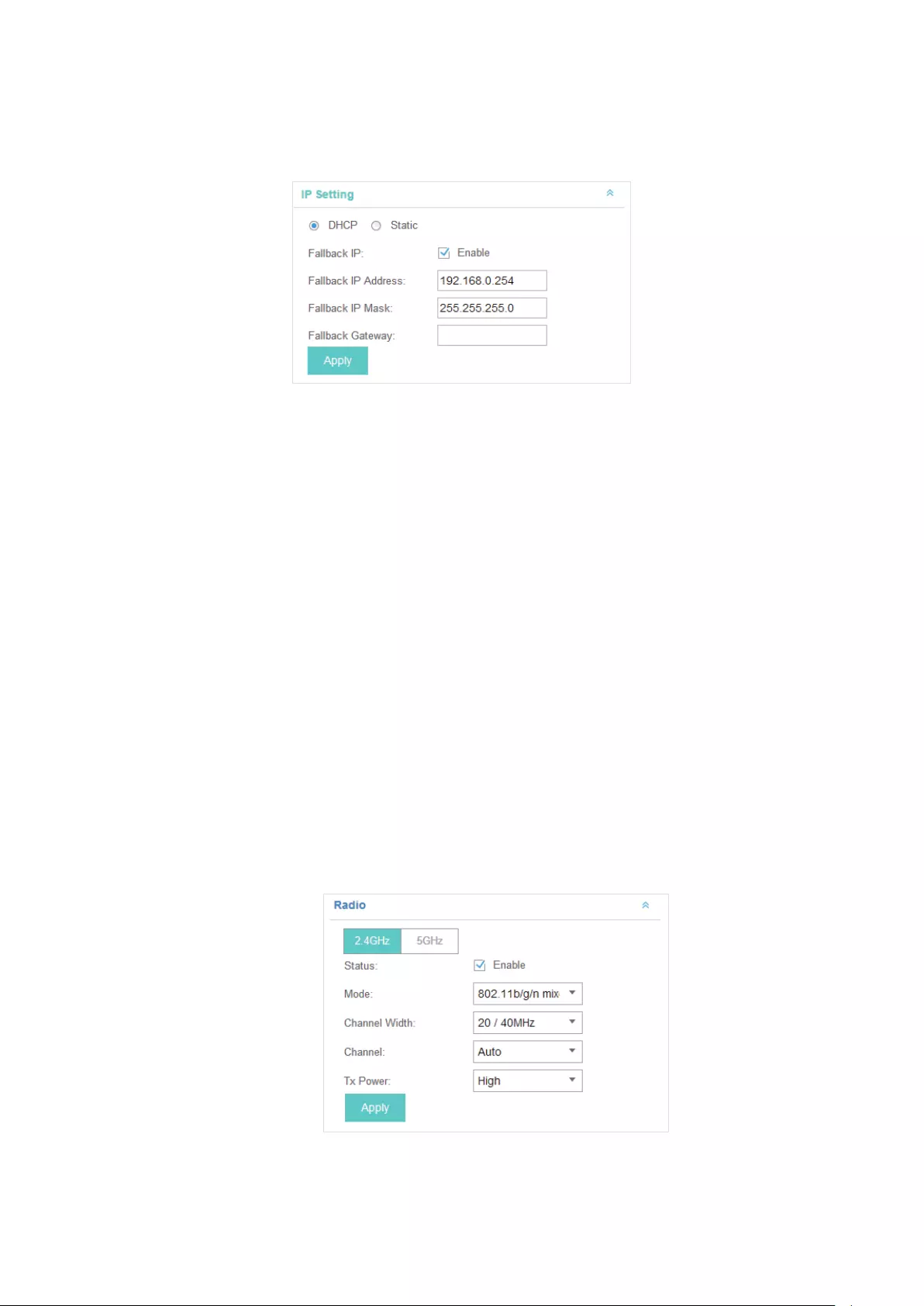
83
4.3.2 IP Setting
You can configure an IP address for this EAP. Two options are provided: DHCP and Static.
Get a Dynamic IP Address From the DHCP Server
1. Congure your DHCP server.
2. Select DHCP on the page above.
3. Enable the Fallback IP feature. When the device cannot get a dynamic IP address, the fallback IP
address will be used.
4. Set IP address, IP mask and gateway for the fallback address and click Apply.
Manually Set a Static IP Address for the EAP
1. Select Static.
2. Set the IP address, IP mask and gateway for the static address and click Apply.
4.3.3 Radio
Radio settings directly control the behavior of the radio in the EAP device and its interaction with
the physical medium; that is, how and what type of signal the EAP device emits.
Select the frequency band (2.4GHz/5GHz) and configure the following parameters.

84
Status Enabled by default. If you disable the option, the radio on the frequency band
will turn off.
Mode Select the IEEE 802.11 mode the radio uses.
When the frequency of 2.4GHz is selected, 802.11b/g/n mixed, 802.11b/g mixed,
and 802.11n only modes are available:
802.11b/g/n mixed: All of 802.11b, 802.11g, and 802.11n clients operating in the
2.4GHz frequency can connect to the EAP device. We recommend you select
the 802.11b/g/n mixed mode.
802.11b/g mixed: Both 802.11b and 802.11g clients can connect to the EAP
device.
802.11n only: Only 802.11n clients can connect to the EAP device.
When the frequency of 5GHz is selected, 802.11 n/ac mixed, 802.11a/n mixed,
802.11 ac onl7, 802.11a only, and 802.11n only modes are available:
802.11n/ac mixed: Both 802.11n clients and 802.11ac clients operating in the
5GHz frequency can connect to the EAP device.
802.11a/n mixed: Both 802.11a clients and 802.11n clients operating in the
5GHz frequency can connect to the EAP device.
802.11ac only: Only 802.11ac clients can connect to the EAP device.
802.11a only: Only 802.11a clients can connect to the EAP device.
802.11n only: Only 802.11n clients can connect to the EAP device.
Channel Width Select the channel width of the EAP device.
For EAP 110/120/220, the options includes 20MHz, 40MHz and 20/40MHz.
For EAP 320/330, the options includes 20MHz, 40MHz, 80MHz and
20/40/80MHz.
The 20/40 MHz and 20/40/80MHz channels enable higher data rates but leave
fewer channels available for use by other 2.4GHz and 5GHz devices. When the
radio mode includes 802.11n, we recommend you set the channel bandwidth to
20/40 MHz or 20/40/80MHz to improve the transmission speed.
Channel Select the channel used by the EAP device to improve wireless performance.
The range of available channels is determined by the radio mode and the
country setting. If you select Auto for the channel setting, the EAP device scans
available channels and selects a channel where the least amount of traffic is
detected.
Tx Power Select the TX Power (transmit power) in the 4 options: Low, Medium, High and
Custom. Low, Medium and High are based on the Max TxPower (maximum
transmit power. It may vary among different countries and regions).
Low: Max TxPower * 20% (round off the value)
Medium: Max TxPower * 60% (round off the value)
High: Max TxPower
Custom: Enter a value manually.
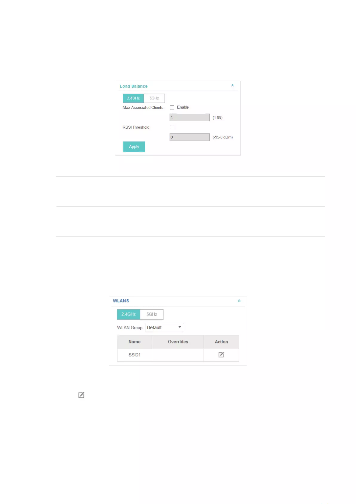
85
4.3.4 Load Balance
By setting the maximum number of clients accessing the EAPs, Load Balance helps to achieve
rational use of network resources.
Select the frequency band (2.4GHz/5GHz) and configure the parameters.
Max Associated
Clients
Enable this function and specify the maximum number of connected clients. While
more clients requesting to connect, the EAP will disconnect those with weaker
signals.
RSSI Threshold Enable this function and enter the threshold of RSSI (Received Signal Strength
Indication). When the clients’ signal is weaker than the RSSI Threshold you’ve set,
the clients will be disconnected from the EAP.
4.3.5 WLANs
You can specify a different SSID name and password to override the previous SSID. After that,
clients can only see the new SSID and use the new password to access the network. Follow the
steps below to override the SSID.
1. Select the frequency band and WLAN group.
2. Click and the following window will pop up.
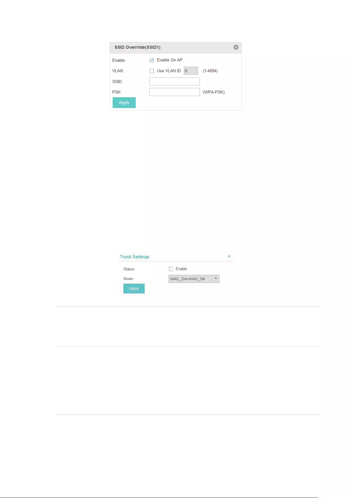
86
3. Check the box to enable the feature.
4. You can join the overridden SSID in to a VLAN. Check the Use VLAN ID box and specify a VLAN
ID.
5. Specify a new name and password for the SSID.
6. Click Apply to save the configuration.
4.3.6 Trunk Settings
Only EAP330 supports this function.
The trunk function can bundles multiple Ethernet links into a logical link to increase bandwidth and
improve network reliability.
Status Enable this function.
The EAP330 has two 1000Mbps Ethernet ports. If the Trunk function is enabled
and the ports are in the speed of 1000Mbps Full Duplex, the whole bandwidth of
the trunk link is up to 4Gbps (2000Mbps * 2).
Mode Select the applied mode of Trunk Arithmetic.
• SRC MAC + DST MAC: When this option is selected, the arithmetic will be based
on the source and destination MAC addresses of the packets.
• DST MAC: When this option is selected, the arithmetic will be based on the
destination MAC addresses of the packets.
• SRC MAC: When this option is selected, the arithmetic will be based on the
source MAC addresses of the packets.
4.3.7 Rouge AP Detection
With this option enabled, the EAP device will detect rouge APs in all channels.
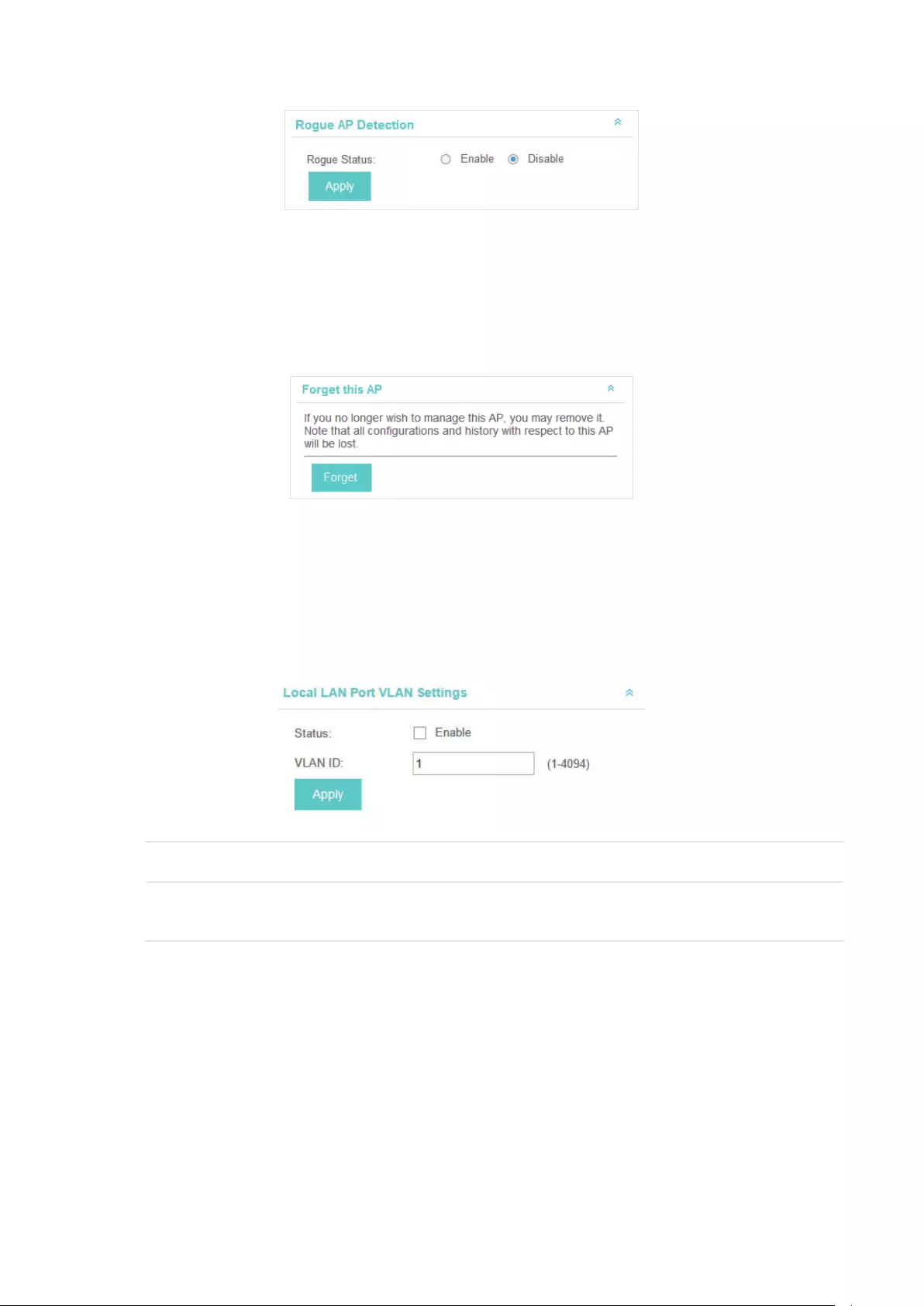
87
4.3.8 Forget this AP
If you no longer want to manage this EAP, you may remove it. All the configurations and history
about this EAP will be deleted. It is recommended to back up the configurations of this EAP before
you forget it.
4.3.9 Local LAN Port VLAN Settings
Only EAP115-Wall supports this function.
This feature is used to add the EAP to a specific VLAN. With this feature enabled, the hosts
connected to this EAP can only communicate with the devices in the same VLAN.
Status Enable this function.
Mode Specify the VLAN that the EAP is added to. The valid values are from 1 to 4094,
and the default is 1.

88
5 Manage the EAP Controller
This chapter mainly introduces how to manage the user account and configure system settings.
This chapter includes the following contents.
·
Information About the Software
·
User Account
·
Controller Settings

89
5.1 Information About the Software
You can view the EAP Controller’s version and copyright information on the About page.
5.2 User Account
You can use different user account to log in to the EAP Controller. User has three roles:
administrator, operator and observer. The administration authority varies among different roles.
Administrator The first administrator account is created in the Basic Configuration process
and this account can not be deleted. An administrator can change the settings
of the EAP network and create and delete user accounts.
Operator An operator account can be created or deleted by the administrator. The
operator can change the settings of the EAP network.
Observer An observer account can be created or deleted by the administrator. The
observer can only view the status and settings of the EAP network but not
change the settings.
Follow the steps below to add user account.
1. Go to Admin > User Settings.
2. Click and the following window will pop up.

90
3. Specify the username, Email and password of the account.
4. Select the role from the drop-down list.
·If you select operator or observer, you also need to select the Site Privileges.
·If you select administrator, the Site Privileges option will not appear and all sites are available for
the administrator user.
5. Click Apply to add the user account.
Note:
You can refer to the Role page to view the user role’s type, description information, permission scope and cre-
ated time.
5.3 Controller Settings
You can configure the EAP Controller’s hostname and IP address. In addition, we recommend you
configure the Mail server to reset your login password when you forget it.
5.3.1 Configure Controller Hostname/IP
Follow the steps below to configure the hostname or IP address of the EAP Controller.
1. Go to Admin > Controller Settings and click EAP Controller.
2. Enter the hostname or IP address of the EAP Controller.
3. Click Apply to save the configuration.
5.3.2 Configure Mail Server
With the Mail Server, you can reset the password of the user account and receive notifications from
the EAP Controller. It is different from the SMTP Server, which is just for the syslog emails sending.
Follow the steps below to configure mail server.
1. Go to Admin > Controller Settings.
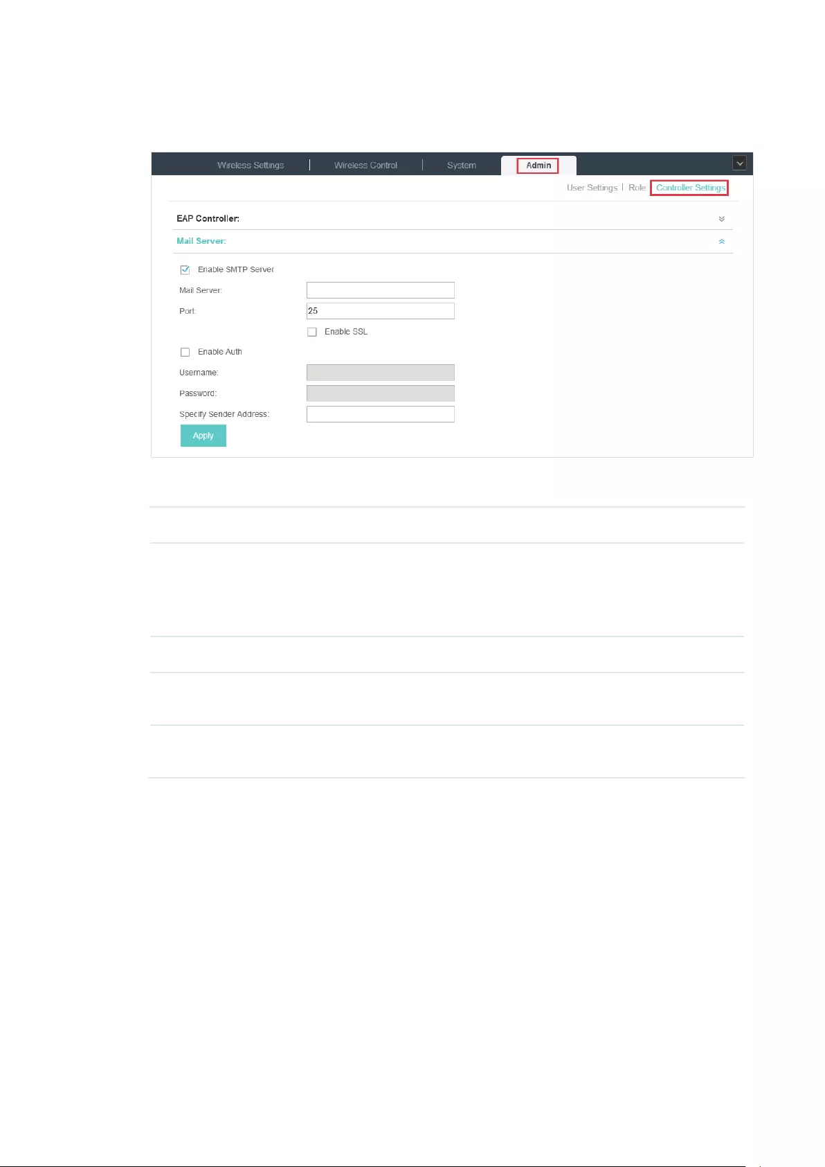
91
2. Click Mail Server, check the box to enable SMTP Server, and then the following screen will
appear.
3. Configure the following parameters.
Mail Server Enter the IP address or domain of SMTP Server.
Port The default is 25.
You can enable SSL (Security Socket Layer) to enhance secure
communications over the Internet. If SSL is enabled, the port number will
automatically change to 465.
Enable Auth Select this option to enable authentication.
Username/Password If you enable authentication, enter the username and password required by
the mail server.
Specify Sender
Address
Specify the sender’s mail address. Enter the email address that will appear
as the sender of the warning email.
4. Click Apply to save the configuration.
Note:
Specify the account email address based on the Mail server to receive the notifications.

92
6 Application Example
A restaurant has a wireless network with three EAPs managed by the EAP Controller. The network
administrator wants to :
·Monitor the EAPs with the Map.
·Enable Portal function to drive customers’ attention to the ads of the supermarket when
customers attempt to access the network. The costumers need to use a simple password to
pass the authentication.
·Allow the employees of the restaurant to access the network resources without portal
authentication.
·Schedule the radio to operate only during the working time (8:00 am to 22:00 pm) in order to
reduce power consumption.
Follow the steps below to achieve the requirements above.
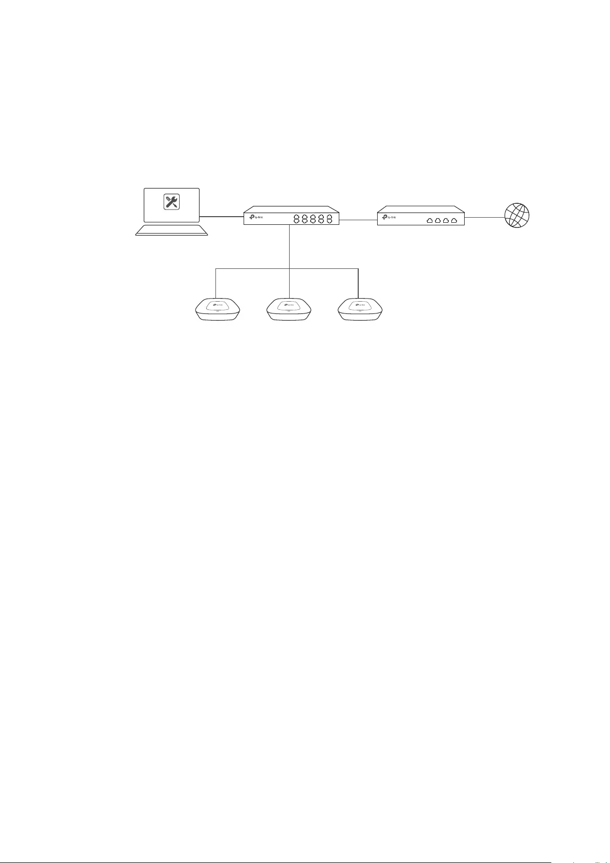
93
6.1 Basic Configuration
Follow the steps below to do the basic configuration.
1. Connect the hardware by referring to the following topology.
Host A (Controller Host)
IP: 192.168.0.100 Switch Internet
EAPs
Router (DHCP Server)
LAN IP:192.168.0.1
EAP Controller
2. Install the EAP Controller on Host A.
3. Launch the software and follow the instructions to complete some initial configurations.
4. Log into the management interface.
5. Adopt the pending EAP devices.
6.2 Advanced Settings
After the basic configuration, refer to the following content to meet the network administrator’s
requirements.
6.2.1 Monitor the EAPs with Map
Follow the steps below to create a map and monitor the EAPs with the map.
1. Go to the Map.
2. Import a local map and set the map scale.
3. Drag the EAPs to the appropriate locations on the map.
4. Click Coverage and you can see the representation of the EAPs’ wireless coverage.
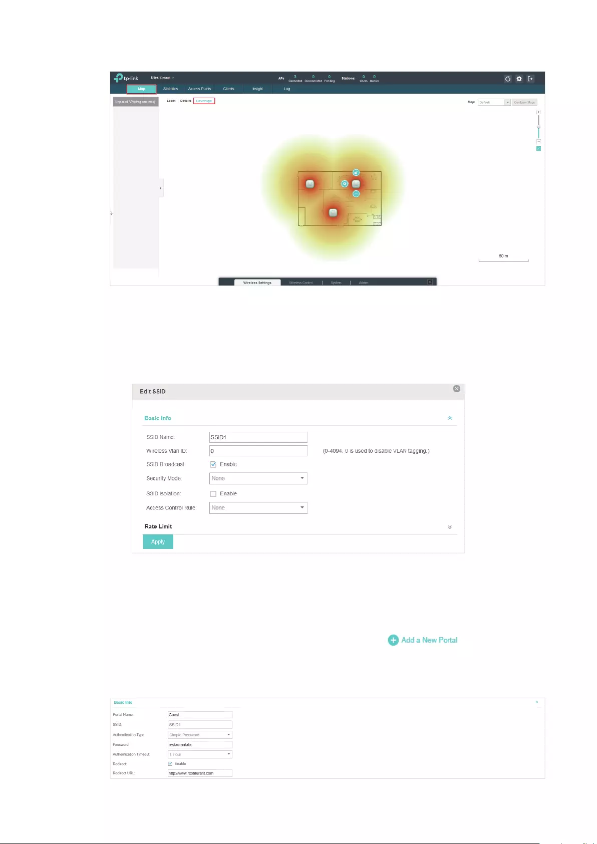
94
6.2.2 Configure Portal Authentication
Follow the steps below to configure Portal function.
1. Go to Basic Wireless Settings and edit the SSID we created in the basic configuration.
To make it easier for customers to connect, change the Security Mode from WPA-PSK to
None. Customers can connect to the EAPs without password and be redirected to the Portal
Authentication where the correct password will be required.
2. Open the global configuration window and go to Portal. Click . The configuration
window will pop up.
3. In the Basic Info section, complete the basic settings for the portal.

95
1 ) Specify a name for the portal.
2 ) Select an SSID for the portal.
3 ) Select the Authentication Type as Simple Password. Specify a simple password for the
guests.
4 ) Select the Authentication Timeout. For example, 1 Hour is suitable for the customers at the
restaurant.
5 ) Enable the Redirect to drive the costumers to the restaurant’s homepage after successful
login. We can put some promotion information on the page.
4. In the Login Page section, configure the login page.
5. In the Advertisement section, upload two pictures of the restaurant and set the related
parameters.
6. Click Apply.
6.2.3 Create a SSID for the Employees
We have created a SSID in the basic configuration for the customers. Here we need to create
another SSID for the employees to allow them to access the network without portal authentication.
In addition, the new SSID should be invisible for the customers.
Follow the steps below to create a SSID for the employees.
1. Open the global configuration window and go to Basic Wireless Settings.
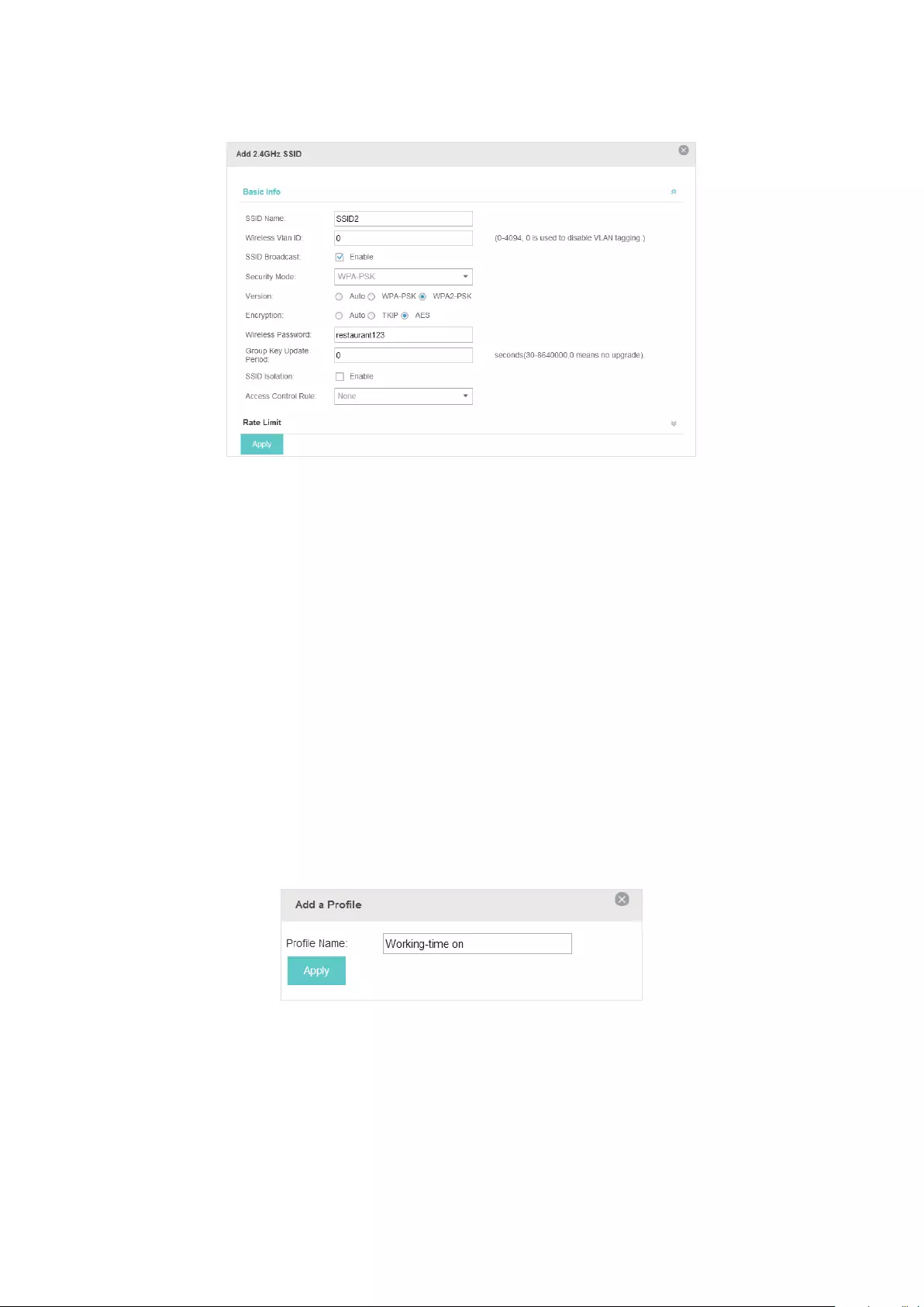
96
2. Click Add to add a new SSID.
Congure the parameters.
1 ) Disable the SSID Broadcast to hide this SSID from the customers.
2 ) Specify the SSID Name, Security Mode and Wireless Password. Let the employees manually
enter the SSID name and password, and choose the security mode you set to access the
network.
3 ) Click Apply to save the conguration.
6.2.4 Configure Scheduler
Follow the steps below to schedule the radio to operate only during the working time (from 8:00 to
22:00).
1. Open the global configuration window and go to Scheduler.
1 ) Add a prole.
2 ) Add an item for the prole. The parameters are set as shown on the following screen.
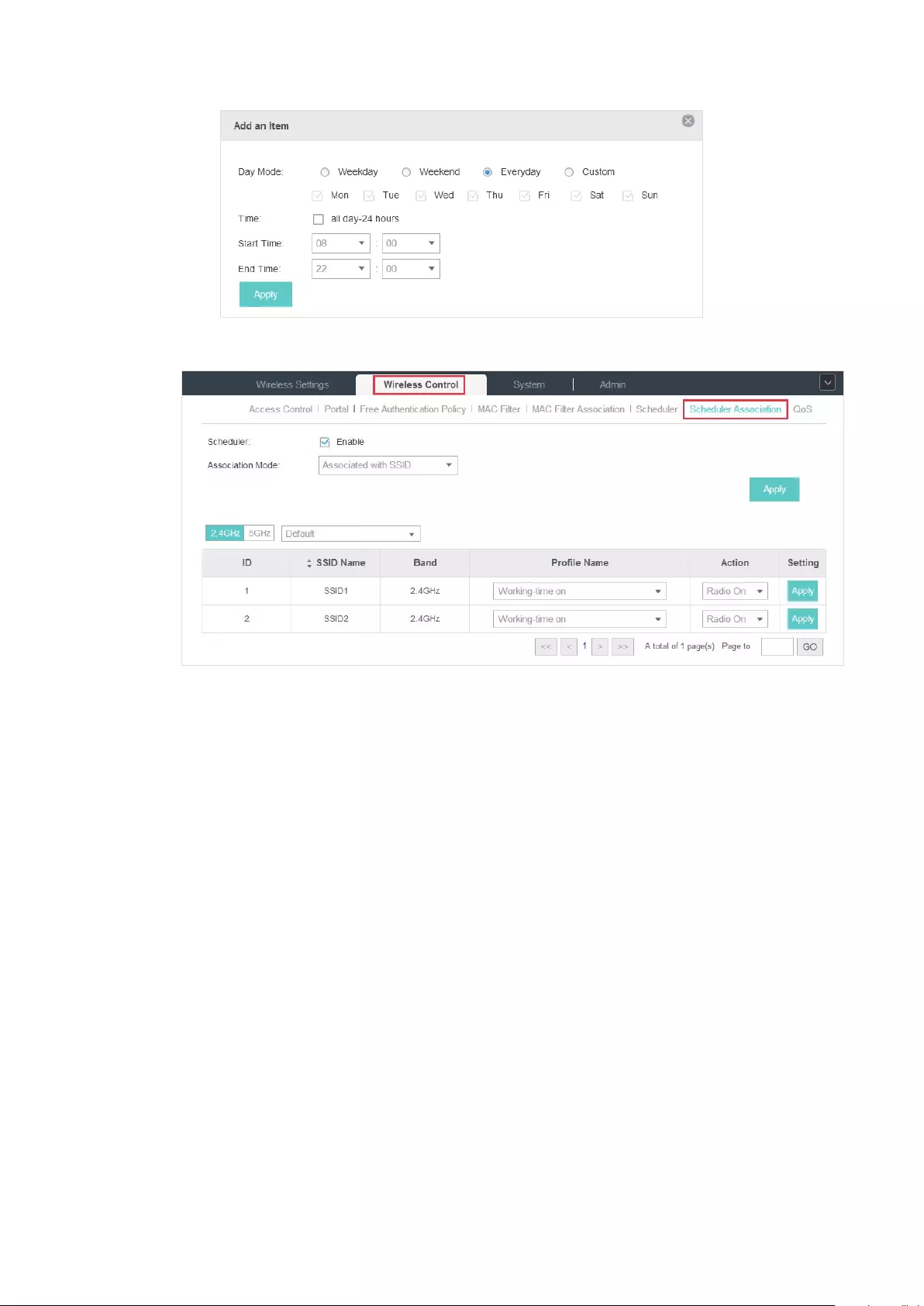
97
2. Go to Scheduler Association tab.
1 ) Enable the function and select Associated with SSID. Click Apply.
2 ) In the Prole Name column of both SSIDs, select the prole we just created.
3 ) In the Action column of both SSIDs, select Radio On.
4 ) Click Apply in the Setting column of both SSIDs.
5 ) Select 5GHz and do the same congurations as above.

COPYRIGHT & TRADEMARKS
Specifications are subject to change without notice. is a registered trademark of TP-Link
Technologies Co., Ltd. Other brands and product names are trademarks or registered trademarks of their
respective holders.
No part of the specifications may be reproduced in any form or by any means or used to make any
derivative such as translation, transformation, or adaptation without permission from TP-Link Technologies
Co., Ltd. Copyright © 2017 TP-Link Technologies Co., Ltd.. All rights reserved.
TP-Link EAP225 — это мощная и надежная точка доступа, которая может обеспечить стабильное беспроводное подключение для вашей домашней или рабочей сети. Но чтобы в полной мере использовать ее возможности, необходимо правильно настроить устройство. В этой статье мы расскажем вам, как выполнить настройку точки доступа TP-Link EAP225, предоставив подробную инструкцию для каждого шага.
Первым шагом при настройке точки доступа TP-Link EAP225 является соединение устройства с вашим роутером или существующей сетью. Для этого подключите точку доступа к источнику питания и используйте сетевой кабель для соединения ее с роутером. Убедитесь, что все соединения надежны и корректны.
После соединения точки доступа с сетью вам необходимо войти в ее управляющую панель через веб-браузер. Для этого введите IP-адрес точки доступа в адресную строку браузера и нажмите клавишу Enter. Вам может понадобиться указать логин и пароль для доступа к панели управления TP-Link EAP225, которые обычно указываются в инструкции к устройству.
Содержание
- Как настроить точку доступа TP-Link EAP225:
- 1. Подключите устройство:
- 2. Подключитесь к точке доступа:
- 3. Откройте веб-браузер:
- 4. Введите IP-адрес точки доступа:
- 5. Введите логин и пароль:
- 6. Настройка сетевых параметров:
- 7. Настройте режим работы:
- 8. Сохраните настройки:
- Подготовка к настройке
- Подключение точки доступа к сети
- Настройка безопасности и аутентификации
- Изменение пароля администратора
- Включение шифрования Wi-Fi
- Настройка гостевой сети
- Фильтрация MAC-адресов
- Обновление прошивки
- Подключение и настройка дополнительных функций
Как настроить точку доступа TP-Link EAP225:
Ниже приведены пошаговые инструкции для настройки точки доступа TP-Link EAP225:
1. Подключите устройство:
Подключите точку доступа TP-Link EAP225 к источнику питания и сетевому коммутатору с помощью соответствующих кабелей.
2. Подключитесь к точке доступа:
Подключите компьютер или ноутбук к точке доступа TP-Link EAP225 с помощью сетевого кабеля или беспроводного подключения Wi-Fi.
3. Откройте веб-браузер:
Откройте веб-браузер на подключенном компьютере или ноутбуке.
4. Введите IP-адрес точки доступа:
Введите IP-адрес точки доступа TP-Link EAP225 в адресной строке веб-браузера. Если вы не знаете IP-адрес, вы можете использовать программу поиска IP-адресов TP-Link на официальном сайте производителя.
5. Введите логин и пароль:
Введите логин и пароль для входа в интерфейс управления точкой доступа TP-Link EAP225. Если вы используете устройство впервые, логин и пароль по умолчанию обычно «admin».
6. Настройка сетевых параметров:
Настройте сетевые параметры точки доступа TP-Link EAP225, включая SSID, тип безопасности, пароль и другие сетевые настройки.
7. Настройте режим работы:
Выберите желаемый режим работы точки доступа TP-Link EAP225, такой как точка доступа (Access Point), усилитель Wi-Fi (Wi-Fi Extender), мост (Bridge) или репитер (Repeater).
8. Сохраните настройки:
После завершения настройки нажмите кнопку «Сохранить» или «Применить» для сохранения всех сделанных изменений.
После выполнения этих шагов точка доступа TP-Link EAP225 должна быть готова к использованию и обеспечивать бесперебойное беспроводное подключение в вашей сети.
Подготовка к настройке
Перед тем как приступить к настройке точки доступа TP-Link EAP225, важно выполнить несколько предварительных шагов, чтобы все прошло гладко:
1. Проверьте комплектацию. Убедитесь, что в комплекте точки доступа есть все необходимые элементы: само устройство, блок питания, Ethernet-кабель и крепление для установки.
2. Установите точку доступа. Выберите оптимальное место для установки устройства, учитывая возможность свободного доступа к нему и наличие питания вблизи.
3. Подключите точку доступа к компьютеру. Используя Ethernet-кабель, подключите точку доступа к доступному порту на вашем компьютере. Убедитесь, что кабель надежно подсоединен с обоими устройствами.
4. Включите точку доступа. Подключите блок питания к точке доступа и подключите его к источнику питания. Дождитесь, пока устройство полностью загрузится.
Подключение точки доступа к сети
Для настройки точки доступа TP-Link EAP225 необходимо сначала подключить ее к сети. Вот пошаговая инструкция:
- Убедитесь, что точка доступа отключена от источника питания.
- Подключите сетевой кабель к порту LAN на точке доступа и к свободному порту на вашем сетевом устройстве (например, компьютере или маршрутизаторе).
- Включите точку доступа, подключив ее к источнику питания.
Теперь точка доступа готова к подключению к сети.
Проверьте, что ваше устройство сети (например, компьютер или маршрутизатор) находится в одной подсети с точкой доступа. Убедитесь, что IP-адрес вашего устройства сети настроен на автоматическое получение (DHCP).
После того как точка доступа подключена к сети, вы сможете настроить ее с помощью веб-интерфейса.
Важно: Проверьте руководство пользователя для получения более подробной информации о настройке и доступе к веб-интерфейсу вашей модели точки доступа TP-Link EAP225.
Настройка безопасности и аутентификации
Изменение пароля администратора
Первым шагом должно быть изменение пароля администратора по умолчанию для точки доступа. Зайдите в веб-интерфейс администратора и найдите раздел «Настройки учетной записи». Здесь вы сможете изменить пароль и установить более безопасную комбинацию символов.
Включение шифрования Wi-Fi
Для защиты вашей беспроводной сети необходимо включить шифрование Wi-Fi. В меню настроек найдите раздел «Беспроводная сеть» и выберите тип безопасности, который вам подходит. Рекомендуется использовать WPA2-PSK, так как это наиболее безопасный стандарт шифрования.
Настройка гостевой сети
Если вам нужно предоставить временный доступ к интернету без предоставления полного доступа к вашей основной сети, рекомендуется настроить гостевую сеть. В меню настроек найдите раздел «Гостевая сеть» и создайте отдельную сеть с ограниченными правами доступа.
Фильтрация MAC-адресов
Фильтрация MAC-адресов — это еще один способ усилить безопасность вашей сети. В меню настроек найдите раздел «Безопасность» и включите фильтрацию MAC-адресов. Затем добавьте разрешенные MAC-адреса устройств, которым разрешен доступ к сети.
Обновление прошивки
Регулярное обновление прошивки вашей точки доступа также важно для обеспечения безопасности. Посетите официальный сайт TP-Link и загрузите последнюю версию прошивки для вашей модели точки доступа. Затем войдите в веб-интерфейс администратора и выполните процесс обновления.
Соблюдение этих рекомендаций поможет вам настроить безопасность и аутентификацию точки доступа TP-Link EAP225 на высоком уровне, обеспечивая защиту вашей сети от несанкционированного доступа и других угроз.
Подключение и настройка дополнительных функций
После успешной настройки базовых параметров точки доступа TP-Link EAP225, можно приступить к подключению и настройке дополнительных функций, которые повысят эффективность работы сети.
1. Подключение к сети
Для установки связи между точкой доступа и маршрутизатором необходимо с помощью сетевого кабеля подключить один из Ethernet портов точки доступа к LAN порту маршрутизатора. Убедитесь, что все подключения осуществляются при выключенном питании устройств.
2. Настройка VLAN
Если необходимо разделить сеть на несколько виртуальных локальных сетей (VLAN), можно настроить VLAN на точке доступа TP-Link EAP225. Для этого перейдите во вкладку «VLAN» в веб-интерфейсе точки доступа. Установите необходимые параметры для каждого VLAN, такие как VLAN ID, имя и доступные порты. После настройки VLAN не забудьте сохранить изменения.
3. Настройка беспроводной безопасности
Для обеспечения безопасности сети настройте беспроводную авторизацию и шифрование. Во вкладке «Беспроводные настройки» в веб-интерфейсе точки доступа выберите тип безопасности (например, WPA2-PSK), задайте пароль и сохраните изменения. Рекомендуется использовать сложный пароль, чтобы предотвратить несанкционированный доступ к сети.
4. Настройка гостевого доступа
Если вы хотите предоставить гостям доступ к интернету, не предоставляя им доступ к вашей основной сети, можно настроить гостевой доступ на точке доступа TP-Link EAP225. Во вкладке «Гостевой доступ» в веб-интерфейсе точки доступа можно указать тип авторизации, разрешенные протоколы, ограничения скорости и другие параметры. После настройки гостевого доступа сохраните изменения и предоставьте гостевую сеть гостям.
5. Настройка контроля скорости
Если необходимо ограничить скорость доступа для определенных клиентов или групп клиентов, можно настроить контроль скорости на точке доступа TP-Link EAP225. Во вкладке «Контроль скорости» в веб-интерфейсе точки доступа выберите нужные параметры ограничения скорости и сохраните изменения. Таким образом, вы сможете более эффективно управлять загруженностью сети и распределить доступную скорость справедливо.
После настройки дополнительных функций убедитесь, что все изменения сохранены и точка доступа TP-Link EAP225 работает стабильно. Теперь вы можете наслаждаться высокоскоростным и безопасным Wi-Fi соединением в своей сети.

 Quick Installation Guide
Indoor/Outdoor Access Point
 Visit https://www.tp-link.com/support/setup-video/ or scan the QR code to search for the setup video of your product model.
 https://www.tp-link.com/support/setup-video/
Overview
Package Contents
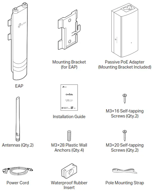 Panel Layout
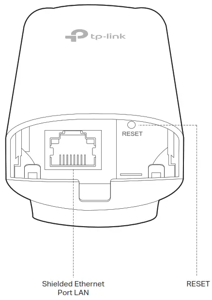 SYS LED Explanation
| LED Status | Indication |
| Flashes green twice | Initialization is completed. |
| Solid green | The device is initializing or working proper |
| Flashing yellow | System errors. RAM, Flash, Ethernet, WLAN or firmware may be malfunctioning. |
| Flashing yellow, green | Firmware update is in progress. Do not disconnect or power off the device. |
| Quickly flashing yellow, green | The device is being reset to its factory default settings. |
| Flashing green slowly (Only for EAP225-Outdoor) | The device is in an isolated state. |
Passive PoE Adapter
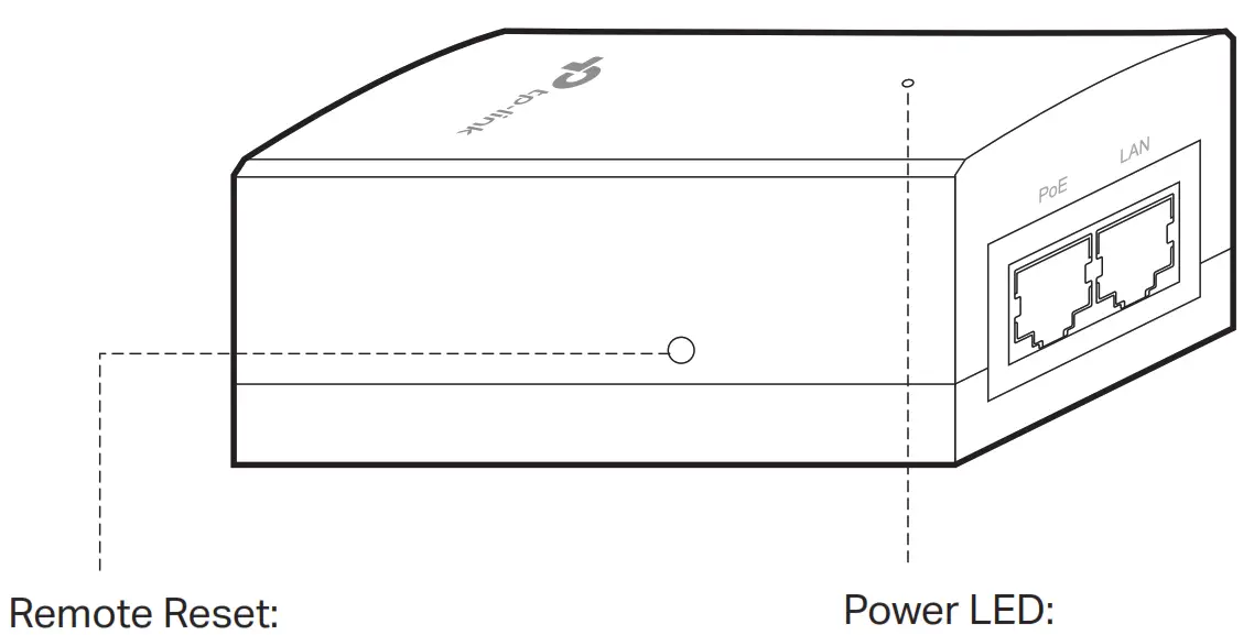
Press and hold for about 8 seconds until the LED is quickly flashing yellow then green. The EAP will restore to factory default settings.
On: Power on, Off: Power off
Note: EAP225-Outdoor does not support the Remote Reset feature
Lightning and ESD Protection
Before mounting the EAP, you should consider Lightning and ESD Protection to ensure safety.
Proper grounding is extremely important for outdoor devices. By using a shielded CAT5e (or above) cable for connection, you can reduce the damage of ESD attacks.
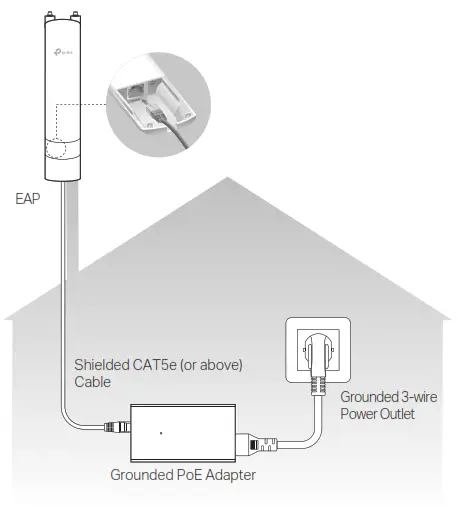
Mount the EAP
The EAP can be pole-mounted or wall-mounted. Follow the steps below for the appropriate installation.
Option 1: Pole Mounting
Step 1:
Lead the end of the pole mounting strap through the back of the EAP.
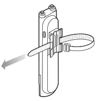
Step 2:
Position the EAP and wrap the pole mounting strap around the pole. Feed the end through the screw-block and tighten the strap until the EAP is secure.
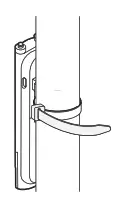
Step 3:
Connect the antennas to the EAP. For optimal Wi-Fi performance, adjust the direction of the antennas. It is recommended to position the antennas at 45-degree angles.
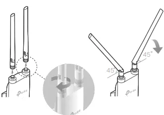
Option 2: Wall Mounting
Step 1:
Place the mounting bracket (for EAP) in the right position. Mark two positions for the screw holes. Drill two 6 mm holes for the screws at the marked positions.
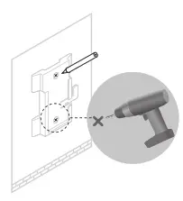 Step 2:
Insert the plastic wall anchors into the 6 mm holes. Align the bracket (for EAP) to the plastic wall anchors and drive the self-tapping screws into the anchors through the bracket (for EAP).
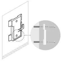 Step 3:
Align the mounting tabs on the back of the EAP with the slot of the mounting bracket (for EAP). Push and slide the EAP downward until it locks into place.
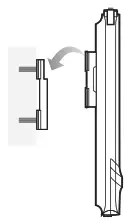
Step 4:
Connect the antennas to the EAP. For optimal Wi-Fi performance, adjust the direction of the antennas. It is recommended to position the antennas at 45-degree angles.
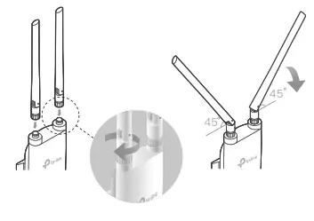
Step 1: Firmly grasp the rear of the interface cover and pull it downward.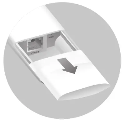 Step 2: Use an adequate Ethernet cable to connect the LAN port. The length of cable is up to 100 m for steady power supply. Shielded CAT5e (or above) cable is recommended.
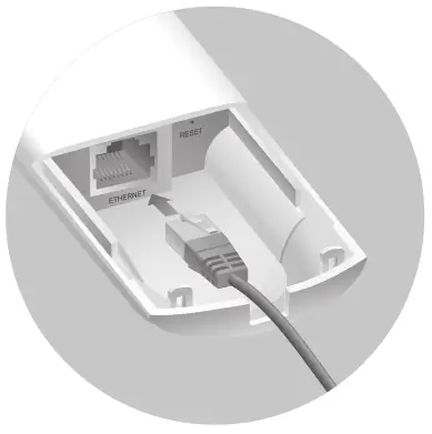
Step 3: Attach the waterproof rubber insert to the groove at the underside of the device for waterproofing. Move the Ethernet cable to the hole of the waterproof rubber insert.
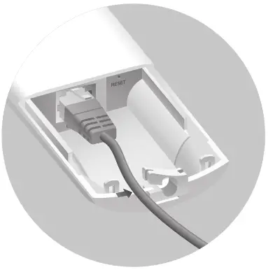 Step 4: Flatten the waterproof rubber insert until it gets parallel to the device. Replace the cover until it firmly locks into place.

Power On
The EAP can be powered via the provided passive PoE adapter or a PSE device (such as a PoE switch). Option 1: Via Passive PoE Adapter Connecting the PoE Adapter Connect the EAP to a Power over Ethernet (PoE) adapter as follows:
Option 1: Via Passive PoE Adapter
Connecting the PoE Adapter
Connect the EAP to a Power over Ethernet (PoE) adapter as follows:
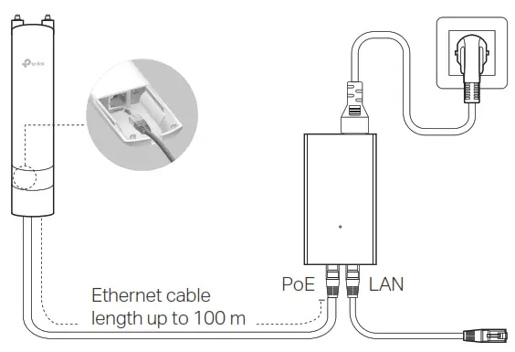
Mounting the PoE Adapter (Optional)
Note: To ensure the passive PoE adapter is attached most securely, it is recommended to install the adapter with the Ethernet port facing upward.
Step 1:
Remove the mounting bracket from the passive PoE Adapter. Drill two holes on the wall and insert the plastic wall anchors into the holes. Secure the mounting bracket to the wall. Make sure the shoulders at the corners of the mounting bracket are on the outside and pointing upward.
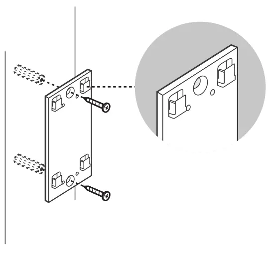 Step 2: Attach the passive PoE adapter to the mounting bracket (for PoE Adapter) by sliding the adapter in the direction of the arrows until it locks into place.
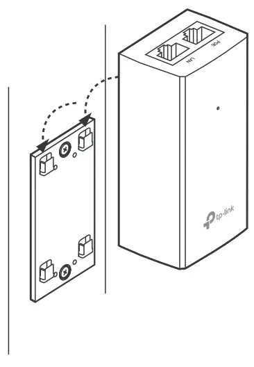 Option 2: Via PoE Switch (Only for EAP225-Outdoor)
Connect an Ethernet cable from the PoE switch to the Ethernet port.
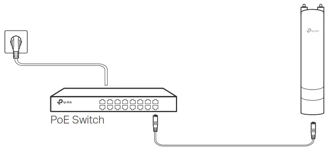
Software Configuration
A DHCP server (typically a router with DHCP function enabled) is required to assign IP addresses to the EAPs and clients in your local network.
The EAP supports two configuring options:
- To configure and manage EAPs singly (usually suitable for a small network with a few EAPs), Standalone Mode is recommended. Please refer to Option1.
- To configure and manage EAPs in batch, Controller Mode is recommended. Please refer to Option 2.
Option1: Standalone Mode
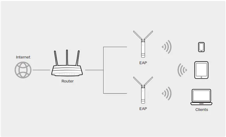
Via Omada App
1. Download the TP-Link Omada App on your mobile device. It can be downloaded from App Store or Google Play:

2. Connect your mobile device to the EAP by using the default SSID (format: TP-Link_2.4GHz/5GHz_XXXXXX) printed on the label at the bottom of the product.
3. Open the Omada App, and wait for the EAP to appear on the Standalone APs page. Tap on the EAP you want to configure.
The Omada App is designed to help you quickly configure the common settings. If you want to configure advanced settings, log in to the web page of your EAP or the controller.
Via a Web Browser
1. Connect wirelessly by using the default SSID (format: TP-Link_2.4GHz/5GHz_XXXXXX) printed on the label at the bottom of the product.
2. Launch a web browser and enter http://tplinkeap.net in the address bar. Use admin for both Username and Password to log in.
3. Set up a new Username and Password for secure management purposes. Modify the wireless parameters and reconnect your wireless devices to the new wireless network.
To configure other EAPs, connect your device to the EAP by the corresponding default SSID and repeat the steps listed above. You can configure some basic functions in Standalone Mode. If you want to configure advanced functions, use Controller Mode.
Option2: Controller Mode
Controller Mode is applicable to configuration for mass EAPs. All EAPs can be centrally configured and monitored via Omada Software Controller, Omada Hardware Controller (OC200/OC300), or Omada Cloud-Based Controller.
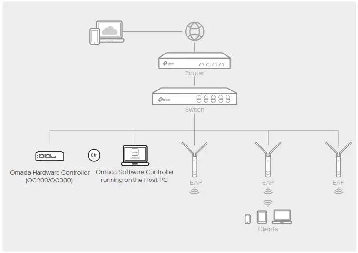
1. On the PC with Windows OS or Linux OS, download the Omada Software Controller installation file from https://www.tp-link.com/support/download/omada-software-controller/.
2. Run the file and follow the wizard to install the Omada Software Controller.
3. Launch the Omada Software Controller and follow the step-by-step instructions to complete the Quick Setup.
4. After the wizard is finished, a login screen will appear. Enter the username and password you created and click Log in. Then you can further configure the controller. Omada Cloud Service After installing Omada Software Controller, you can remotely access and configure the controller through
Omada Cloud Service. Follow the steps below.
1. Enable Cloud Access on the setting page on the controller and bind a TP-Link ID to your controller. If you have configured this in the setup wizard, skip the step.
2. Launch a web browser and enter https://omada.tplinkcloud.com in the address bar.
3. Enter your TP-Link ID and password to log in. A list of controllers that have been bound with your TP-Link ID will appear. Then you can click Launch to further
configure the controller.
Omada App
With Omada App, you can also manage your Omada Software Controller at a local site and remote site. Note that Omada Software Controller needs to be kept running when using Omada App.
1. Download the TP-Link Omada App on your mobile device. It can be downloaded from App Store or Google Play:
 Scan for Omada App – https://www.tp-link.com/common/app/omada/qrcode.php
2. Launch your Omada App and configure the controller at local a site or remote site.
Local Managementa.
Connect your mobile device to the EAP by using the default SSID (format: TP-Link_2.4GHz/5GHz_XXXXXX) printed on the label at the bottom of the product.
b. Launch Omada App and go to Local Access, tap the + button on the upper-right corner to add the controller. Then you can further configure the controller.
Remote Managementa.
Make sure Cloud Access is enabled on your controller and your controller has been bound with your TP-Link ID.
b. Launch Omada App and log in with your TP-Link ID. Then go to Cloud Access. A list of controllers that have been bound with your TP-Link ID will appear. Then you can further configure the controller.
Via Omada Hardware Controller (OC200/OC300)
Omada Hardware Controller (OC200/OC300), which is pre-installed with Omada Software Controller, is a good alternative if you have no spare PC to keep running Omada Software Controller in the network. It needs to be purchased additionally. For more details, refer to the Installation Guide of OC200/OC300.
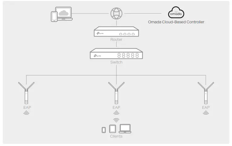
Via Omada Cloud-Based Controller
1. Launch a web browser and enter https://omada.tplinkcloud.com in the address bar. Then enter your TP-Link ID and password to log in.
2. Click Add Controller and subscribe to Omada Cloud-Based Controller. Follow the instructions to choose a plan and complete the payment. Then wait until your controller is deployed.
3. The controller will appear in the list once bound with your TP-Link ID. Click Launch and follow the step-by-step instructions to complete the Quick Setup. After the wizard is finished, log in via the created username and password.
4. Click Devices on the side bar and then click Add Devices. Then you can add devices to the controller manually through the serial numbers at the bottom of the product. Omada App With Omada App, you can also manage your Omada Cloud-Based Controller.
1. Download the TP-Link Omada App on your mobile device. It can be downloaded from
App Store or Google Play:
 2. Launch Omada App and log in with your TP-Link ID. Then go to Cloud Access. A list of controllers that have been bound with your TP-Link ID will appear. Then you can further configure the controller.
Attention:
For EAP225-Outdoor, in EU member states and EFTA countries, the operation in the frequency range 5150MHz-5350MHz is only permitted indoors. For EAP Controller, go to Access Point page and select the desired EAP to specify the channel. For web browser, go to Wireless > Wireless Settings to specify the channel.
| AT | BE | BG | CH | CY | CZ | DE | DE | EE | EL | ES | FI | FR | HR | HU | IE |
| IS | IT | LI | LT | LU | LV | MT | NL | NO | PL | PT | RO | SE | SI | SK | UK |
For detailed configurations, please visit https://www.tp-link.com/support to download the User Guide of EAP in the download center.
 To ask questions, find answers, and communicate with TP-Link users or engineers, please visit https://community.tp-link.com to join TP-Link Community.
 For technical support, the user guide and other information, please visit https://www.tp-link.com/support, or simply scan the QR code.

http://www.tp-link.com/support
 If you have any suggestions or needs on the product guides, welcome to email [email protected].
 Safety Information
Keep the device away from water, fire, humidity, or hot environments. Do not attempt to disassemble, repair, or modify the device. If you need service, please contact us. Do not use the device where wireless devices are not allowed. Do not use any other chargers than those recommended. Adapter shall be installed near the equipment and shall be easily accessible. The products of TP-Link partly contain software code developed by third parties, including software code subject to the GNU General Public License (“GPL”). As applicable, the terms of the GPL and any information on obtaining access to the respective GPL Code used in TP-Link products are available to you in GPL-Code-Centre under (https://www.tp-link.com/en/support/gpl/). The respective programs are distributed WITHOUT ANY WARRANTY and are subject to the copyrights of one or more authors. For details, see the GPL Code and other terms of the GPL.