
CNC инструкция по эксплуатации
1. Сборка станка.
Пожалуйста, обратитесь к «Инструкции по сборке» для сборки станка (скачать можно в данном разделе https://minichpu.ru/page/1279409).
2. Отладка (для начала скачайте «Полный пакет» в разделе https://minichpu.ru/page/1279409).
Для начала необходимо подключить плату к сети с помощью болка питания, а также соединить плату с компьютером (ноутбуком) с помощью кабеля USB, входящего в комплект.
— Установить драйвер CH340SER (путь- /driver/).
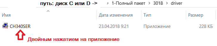
— Открываем двойным нажатием, появляется сообщение
«Разрешить этому приложению вносить изменения на вашем устройстве?»
Нажимаем – ДА!
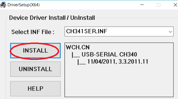
Появляется окно:
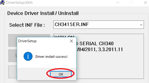
Нажимаем INSTALL, драйвер устанавливается, и появляется окно, что успешно установлен (Driverinstallsuccess!), нажимаем ОК. И закрываем окно.
Определение COM-порта компьютера (для инфо):
- Windows XP: Щелкните правой кнопкой мыши на «мой компьютер», выберите «Свойства», выберите «Диспетчер устройств».
- Windows 7: Нажмите «Пуск» -> щелкните правой кнопкой мыши «компьютер» -> выберите «Управление» -> выберите «Диспетчер устройств» из левой панели.
- В дереве разверните «порты (COM & LPT)»
- Ваш станок будет USB последовательный порт (СОМХ), где “X” представляет собой номер COM порта, например СОМ6.
- Если есть несколько USB-портов, щелкните каждый из них и проверить производителя, станок будет «CH340».
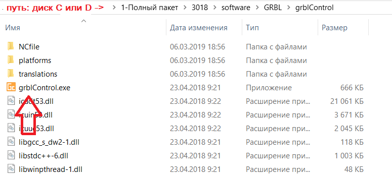
3. Раскройте контрольную программу grblControl.exe, чтобы соединить станок и выбрать правильный порт:
— Открываем двойным нажатием, (станок должен быть подключен и в сеть и через USB).
— Выбираем в меню Сервис ->Настройки, далее Порт (обновляем, и из выплывающего меню выбираем другой порт), нажимаем ОК. Статус меняется на ГОТОВ.
(изначально Статус – Нет соединения)
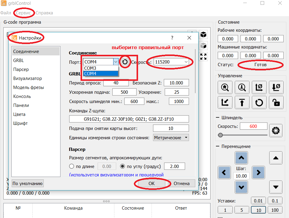
В консоле (внизу): Соединение успешно установлено:[CTRL+X] < Grbl 0.9j [‘$’ forhelp]
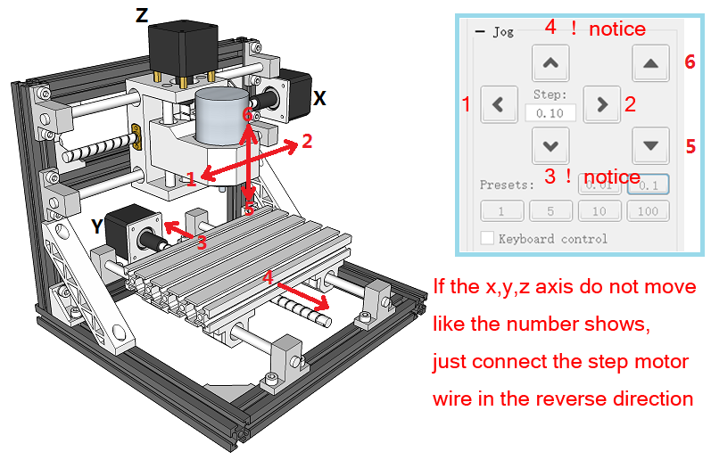
4. Проверить направление оси XYZ:
Если ось x, y, z не двигается, как показано на рисунке, просто подключите провод шагового двигателя в обратном направлении.
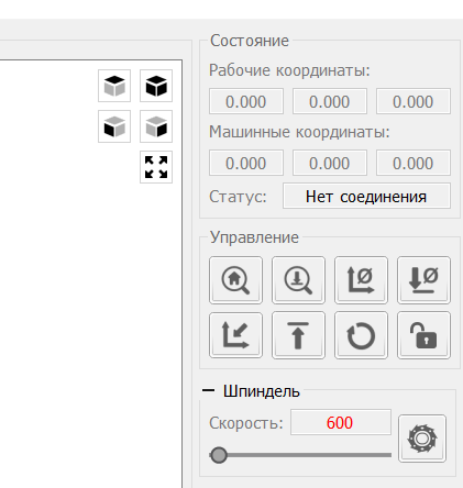
Как обнулить положение гравера:
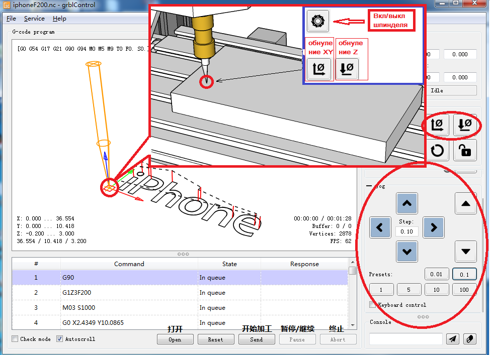
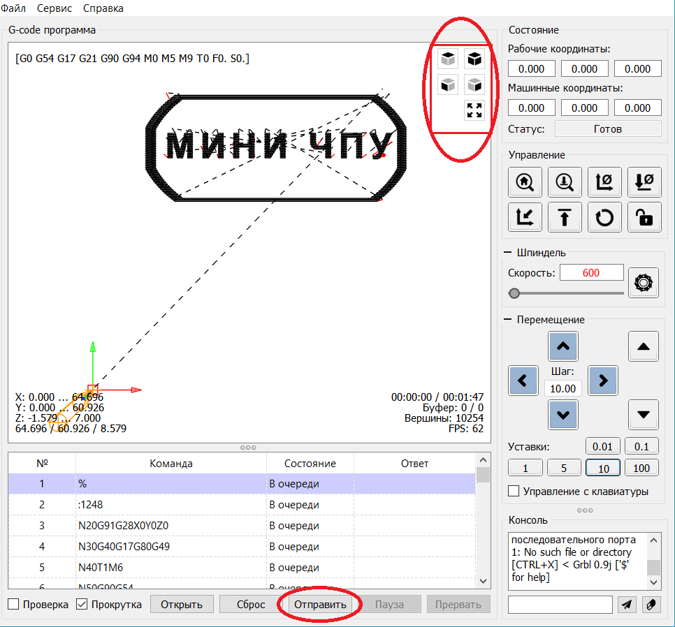
5. После установки станка, откройте файл гравировки — приложение «grblControl.exe» (путь- 3018/software/GRBL/grblControl). В правом верхнем углу статус должен быть ГОТОВ. Необходимо определить, где будет находится нулевая точка. Обычно в левом нижнем углу заготовки.
Сначала подведите шпиндель в левый нижний угол заготовки (с помощью кнопок перемещения X и Y), затем опустите фрезу по оси Z. Замедлить движение можно уменьшив шаг, нажатием кнопок 0,01; 0,1; 1; 5; 10 (расположенные ниже стрелок перемещения).
Когда резец будут приближаться к заготовке, аккуратно подведите его к поверхности заготовки.
Важно! После соприкосновения резца с поверхностью, нажмите в разделе управление кнопки «Обнулить XY» и «Обнулить Z«.
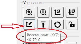
Подсказка: лучше всего опробовать станок на работоспособность без заготовки. Для вращения шпинделя нажмите кнопку «Вкл/Выкл шпиндель», также можно изменять скорость вращения. Произведите перемещение по всем осям. Для возвращения в нулевую точку необходимо нажать кнопку в управлении «Восстановить XYZ«.
Проверьте станок, прежде чем начать официальную гравировку.
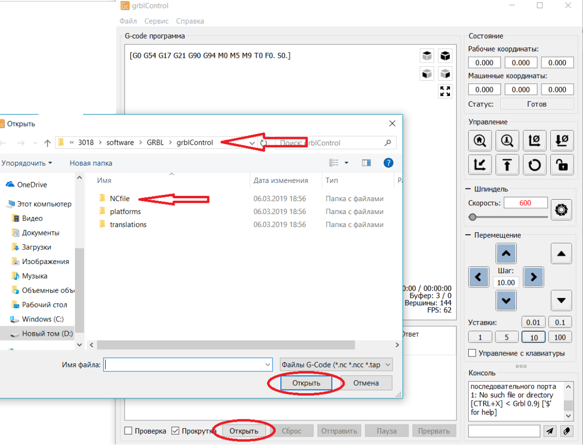
6. Загрузка файла в управляющую программу grblControl.
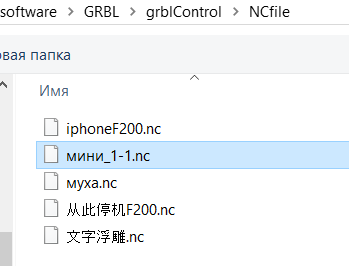
Затем вы можете нажать кнопку «Открыть» в нижнем углу, выбрать из папки «NCfile» готовый файл (с расширением *.nc), чтобы выгравировать.
7. В папке хранятся готовые файлы.
Этапы работы станков с ЧПУ:
1) формируется модель с помощью специальных графических программ (ArtCam и т.д.) на компьютере.
2) с помощью специальной программы для станка с ЧПУ готовая модель отцифровывается в управляющую программу с расширением *.nc.
3) потом файл открывают управляющей программой «grblControl.exe» и вносят в память ЧПУ. И станок приступает к работе.
Изучайте графическую программу ArtCam, создавайте модели и реализовывайте их с помощью станка CNC 3018.
Подготовлено при участии магазина МИНИ ЧПУ https://minichpu.ru
-

НОВИНКА Инструкцией от offline controller(а) CNC 3018
Инструкция на новый тип платы, «бескомпьютерная»
- Lex Davidoff
- Обновлено:
-
НУЖНО ИНСТРУКЦИЯ ПО СБОРКЕ
Станка типа CNC3018
- Андрей
- Обновлено:
-
ПОЛЕЗНО Справочное руководство по CorelDRAW-2018 (рус.)
Справочное руководство на русском языке по CorelDRAW
- Андрей
- Обновлено:
-
ИНТЕРЕСНО 300 практических советов
Литература прошлого века
- Андрей
- Обновлено:
-
ИНТЕРЕСНО Знай и Умей
Для ценителей Советской литературы из рубрики Работы по дереву 1962 г.
- Дядя Вова
- Обновлено:
![]()
![]()
Table of Contents: CNC 3018 Printer Owner’s Manual
-
CNC 3018 LaserGRBL LaserGRBL is an excellent and practical open source control software in the field of laser engraving. Compared with similar software, it has a simple interface, simple operation, and supports multiple languages. There are a lot of learning resources used on the Internet, which is convenient for beginners to understand and master the software. Mastering a laser engraving software is the basic condition for using a laser engraving machine. It is recommended that beginners first learn the operation method of the
-
2cm 12
-
CNC 3018 3018 Machine Assemble 022: Corner pieces*1 pc 019:T-nut M5*2 pcs 027:Gasket M5*2 pcs 017: M5-10*2 pcs screw 003: Aluminum Profile330mm*2 root 002: Aluminum Profile360mm*3 root 56mm 1 3
-
CNC 3018 Q: What is the reason why the engraved picture is very light? Quality: ** line / mm, generally set to 10 lines / mm, the larger the value, the darker the color, the set according to your needs Engraving speed: the moving speed when the laser is turned on, the faster the speed is engraved the shallower. Minimum maximum power: The general minimum power is set to 0 and the maximum power is set to 1000. The greater the maximum power, the deeper the engraved color. Q: Why does the fan of the laser module not turn? Please confirm that the laser head is working
-
6.Click “Next” to pop up the “Target Image” dialog box, where you can set the engraving speed, minimum power and maximum power and the length and width of the image to be engraved and offset. Click “Create” after setting. Move to the position you want to engrave, click the “Position” button (the position where the laser head is located at the lower left corner of the engraved pattern), set the number of times to be engraved, and click the “Start E
-
CNC 3018 12 Laser on Machine Machine Assemble 13 How to connect 13 Package 14 Candle software 19 LaserGRBL 24 Offline instructions 25 FAQ
-
CNC 3018 6. Set the working coordinate origin Before running the G code program, you need to find the position of the engraving figure relative to the overall engraving plate. There is a three-axis coordinate system in the visual graphics. The origin of the three-axis coordinate system is the tool setting point of the actual processing graphic. You can move the tool to determine the position of the engraving graphic relative to the overall engraving plate based on the position of this origin. The engraving figure in the figure below is taken as an exampl
-
CNC 3018 1. Boot page: X+: right X-: left Y+: Send $X to the grbl motherboard to unlock the grbl board. Y-: Send $H to the grbl motherboard to achieve automatic zero return of the grbl board. OK/SPN: Confirm button. Move the page: Manually move each axis to the desired position. X+: Y+: OK/SPN: Spindle test switch, press to open the spindle (corresponding to SPN gray on the screen), press again to close the spindle (the corresponding SPN on the screen returns to normal). Exit/STP: Function 1: Tap on each axis button of XYZ to change the movement distance by 0.1, 1, 5, 10 cycles each time. Fu
-
CNC 3018 4.After the connection is successful, click “File” on the menu bar of the interface to enter the selection file interface, select “Open File”, import the picture to be carved, etc. 5.Select the file to be engraved, click “Open”, the “Input Raster Image” dialog box will pop up. Here is the setting engraving mode and some other engraving parameters. Click “Next” after setting. 20
-
4. Connection is complete After setting the port and baud rate, click Finish. The status bar at the top right of the Candle interface will show Idle, and at the same time, the console at the bottom right will display the information shown below, indicating that the connection has been successfully established. 15
-
CNC 3018 017: M5-10*2 pcs screw 027: M5 Gasket*2 pcs 019: T nut*2pcs 019: T nut*2pcs 022: Corner piece*1pc 016: M5-8*2 pcs screw Flat bracket*1 pc 002:2020-360mm*2 root 004:2020-220mm*2 root 56mm 12 13 8
-
CNC 3018 033: Motor mounting plate*1pc 010: Stepper Motor*1 pc 015:M3-6*4pcs Screw 5 019:T nut*2 pc 017: M5-10*2 pcs screw 027:M5 Gasket*2 pcs 5
-
CNC 3018 5. Processing documents The «File» option at the top, click «New» to create a G code in the command bar at the bottom of the interface, and click «Open» to select a G code file that has been made, and then you can import the file. After importing, the middle of the interface will display a visual graph composed of tool paths (the position of the pen-shaped graph in the graph is the current tool position). In the visualization window, hold down the left mouse button to move to rotate the graph, and hold down the right button to move. Graphics, scrol
-
CNC 3018 3018\2418\1610 CNC Engraving Machine
-
CNC 3018 033: Motor mounting plate*1pc 010: Stepper Motor*1 pc 017:M5-10*2 pcs screw 027: Gasket*2 pcs 015:M3-6*4 pcs screw 019: T nut*2 pcs 017:M5-10*1 pc screw 019: T nut*1 pc 034: X-bearing*1 pc 18 19 10
-
CNC 3018 Package How to connect 13
-
User manual 1.Overview Candle is an open source software suitable for CNC machine tool processing. It supports G code file processing and visual display. 2.Install the driver For the first time use, please connect the device to the computer via USB cable, and click the CH340-Driver.exe file in the driver folder to install the driver. Under normal circumstances, the Win10 system will automatically identify and install the driver. For Win7 and Win8 systems, please install it manually. Driver insta
-
CNC 3018 017:M5-10*4 pcs screw 011:Controller*1 pc 019: T nut*4 pcs 030:ABS isolation column*4 pcs 20 11
-
026:Coupling*1 pc 006:Optical axis 400mm*1 root 017: M5-10*8 pcs screw 019: T nut*8pcs 023:Support*4 pcs 005: Z-Axis*1set Spring*1 008:T8-400mm*1 pc 021:Copper nut*1 pair 15 16 17 14 9
-
017: M5-10*8 pcs screw 019: T nut*8 pcs 025: Linear Bearings*2 pcs 023: Support*1 pc 007: Optical axis 330mm*1 root Y axis assemble belt 018:M6-12*10 pcs screw 020:Slide nut*10 pcs 8 7 6 6
-
3018/2418/1610 CNC Engraving Machine
-
CNC 3018 Copper nut 2 Corner piece 2028 Pitch 2 Lead 4 16 Support Nut seat SK10 T8 8 1 Linear Bearings LM10UU 10*19*29 power supply ABS isolation column Drill Bit Optional 500mw 15000w 1600mw 2500mw 1 Inch Offline 1.8 Inch Offline 3500mw Motor mounting plate ER11 X-bearing Y-bearing DC24V5A 11*5.2*5 3.175*30°0.1 C16-ER11-35L 5mm / / / / / / / 1 Word support 2 1 1 1 Pressure plate Flash Memory Disk Package 2/2.5/3/4/5 1 Socket wrenches 026 Coupling 027 028 029 030 031 032 033 034 035 036 037 038 039 Gasket 5*8 M5 36 2 1 4 1 1 2 1 4 025 Pair Pc Pc Pc Pc Pc Pc Pc Pc Pc Pc Pc Pc Pc Set Set Set Set Box 2
-
CNC 3018 7.Start Carving After finding the engraving position, click the send button below and the device will automatically start engraving. The status bar at the top right shows running. The visualization window shows that the tool is moving along the tool path. You can choose the pause and stop buttons below when engraving. (After pausing, click again to continue the previous engraving. After termination, click Send to start processing from the beginning). 8.Finished processing After the processing is completed, the visualization window prompts that the engraving is completed and the time required for engraving. 18
-
035: Y-bearing*1 pc 017:M5-10*2 pcs screw 019:T nut*2 pcs Note: Place the center of the profile 026:Coupling*1 pc 021:Copper nut*1 pair Spring*1 024:Nut seat*1 pc 009:Lead screw320mm*1 pc 2 3 4 4
-
9 10 11 001:Aluminum Profile*1 root 7
-
CNC 3018 Engraving material list Problem summary The data listed in this list are all reference values. Because each material has different characteristics and differences, there is a certain error. In general, the use of relatively high power (1600MW is relatively high power compared to 500MW), the engraving depth is relatively deep, but due to the focal length, it will be less detailed than the low power. Small power engraving is shallow but very fine. When engraving, you can adjust the power, engraving speed, and moving speed for better results. In addition, when the speed is slow, it can b
-
Q: How to use 500mw -15000mw laser A: 1. 500mw-3500mw laser , please place the material flat under the laser, and make the distance between them within 5~10cm ;5500mw laser within 3-5cm (less distance will not be able to focus). Press the power switch on the laser driver, then the blue light on . Open the software click weak power, there will be a point on engraved material, just turn around the focus ring on laser to adjust the smallest which is the best focus. 2.15000mw laser is fixed fo
-
2020*220mm M3*6 Optical axis Optical axis Z-Axis Lead screw Lead screw Stepper Motor 3.0 Controller USB Cable 775 Motor Cable Stepper Motor Cable Hexagon Socket Screw Hexagon Socket Screw Hexagon Socket Screw Hexagon Socket Screw M5*8 M5*10 T nut Slide nut M6*12 15180*300mm 2020*360mm 2020*330mm Z-axis Φ10*400mm Φ10*330mm T8*400mm T8*320mm 42HS34-13D GRBL 1.1 1500mm 500mm 600mm M6 M5 1 5 2 2 1 2 2 1 1 2 1 1 1 3 8 4 59 10 63 10 Pc Pc Pc Pc Pc Pc Pc Pc Pc Root Root Root Root Root Root Root Root Root Root Set 017 1
Questions, Opinions and Exploitation Impressions:
You can ask a question, express your opinion or share our experience of CNC 3018 device using right now.
Table of Contents: CNC 3018 Printer Owner’s Manual
-
026:Coupling*1 pc 006:Optical axis 400mm*1 root 017: M5-10*8 pcs screw 019: T nut*8pcs 023:Support*4 pcs 005: Z-Axis*1set Spring*1 008:T8-400mm*1 pc 021:Copper nut*1 pair 15 16 17 14 9
-
CNC 3018 3018\2418\1610 CNC Engraving Machine
-
CNC 3018 Package How to connect 13
-
CNC 3018 2cm 12
-
User manual 1.Overview Candle is an open source software suitable for CNC machine tool processing. It supports G code file processing and visual display. 2.Install the driver For the first time use, please connect the device to the computer via USB cable, and click the CH340-Driver.exe file in the driver folder to install the driver. Under normal circumstances, the Win10 system will automatically identify and install the driver. For Win7 and Win8 systems, please install it manually. Driver install(X64) Driver
-
Engraving material list Problem summary The data listed in this list are all reference values. Because each material has different characteristics and differences, there is a certain error. In general, the use of relatively high power (1600MW is relatively high power compared to 500MW), the engraving depth is relatively deep, but due to the focal length, it will be less detailed than the low power. Small power engraving is shallow but very fine. When engraving, you can adjust the power, engraving speed, and moving speed for better results. In addition, when the speed is slo
-
Copper nut 2 Corner piece 2028 Pitch 2 Lead 4 16 Support Nut seat SK10 T8 8 1 Linear Bearings LM10UU 10*19*29 power supply ABS isolation column Drill Bit Optional 500mw 15000w 1600mw 2500mw 1 Inch Offline 1.8 Inch Offline 3500mw Motor mounting plate ER11 X-bearing Y-bearing DC24V5A 11*5.2*5 3.175*30°0.1 C16-ER11-35L 5mm / / / / / / / 1 Word support 2 1 1 1 Pressure plate Flash Memory Disk Package 2/2.5/3/4/5 1 Socket wrenches 026 Coupling 027 028 029 030 031 03
-
12 Laser on Machine Machine Assemble 13 How to connect 13 Package 14 Candle software 19 LaserGRBL 24 Offline instructions 25 FAQ
-
3018 Machine Assemble 022: Corner pieces*1 pc 019:T-nut M5*2 pcs 027:Gasket M5*2 pcs 017: M5-10*2 pcs screw 003: Aluminum Profile330mm*2 root 002: Aluminum Profile360mm*3 root 56mm 1 3
-
CNC 3018 017: M5-10*8 pcs screw 019: T nut*8 pcs 025: Linear Bearings*2 pcs 023: Support*1 pc 007: Optical axis 330mm*1 root Y axis assemble belt 018:M6-12*10 pcs screw 020:Slide nut*10 pcs 8 7 6 6
-
033: Motor mounting plate*1pc 010: Stepper Motor*1 pc 017:M5-10*2 pcs screw 027: Gasket*2 pcs 015:M3-6*4 pcs screw 019: T nut*2 pcs 017:M5-10*1 pc screw 019: T nut*1 pc 034: X-bearing*1 pc 18 19 10
-
CNC 3018 LaserGRBL LaserGRBL is an excellent and practical open source control software in the field of laser engraving. Compared with similar software, it has a simple interface, simple operation, and supports multiple languages. There are a lot of learning resources used on the Internet, which is convenient for beginners to understand and master the software. Mastering a laser engraving software is the basic condition for using a laser engraving machine. It is recommended that beginners first learn the operation method of the software online before using it to prevent damage to the laser engraving machine and surrounding items by improper o
-
CNC 3018 9 10 11 001:Aluminum Profile*1 root 7
-
1. Boot page: X+: right X-: left Y+: Send $X to the grbl motherboard to unlock the grbl board. Y-: Send $H to the grbl motherboard to achieve automatic zero return of the grbl board. OK/SPN: Confirm button. Move the page: Manually move each axis to the desired position. X+: Y+: OK/SPN: Spindle test switch, press to open the spindle (corresponding to SPN gray on the screen), press again to close the spindle (the corresponding SPN on the screen returns to normal). Exit/STP: Fu
-
CNC 3018 2020*220mm M3*6 Optical axis Optical axis Z-Axis Lead screw Lead screw Stepper Motor 3.0 Controller USB Cable 775 Motor Cable Stepper Motor Cable Hexagon Socket Screw Hexagon Socket Screw Hexagon Socket Screw Hexagon Socket Screw M5*8 M5*10 T nut Slide nut M6*12 15180*300mm 2020*360mm 2020*330mm Z-axis Φ10*400mm Φ10*330mm T8*400mm T8*320mm 42HS34-13D GRBL 1.1 1500mm 500mm 600mm M6 M5 1 5 2 2 1 2 2 1 1 2 1 1 1 3 8 4 59 10 63 10 Pc Pc Pc Pc Pc Pc Pc Pc Pc Root Root Root Root Root Root Root Root Root Root Set 017 1
-
CNC 3018 033: Motor mounting plate*1pc 010: Stepper Motor*1 pc 015:M3-6*4pcs Screw 5 019:T nut*2 pc 017: M5-10*2 pcs screw 027:M5 Gasket*2 pcs 5
-
CNC 3018 Q: What is the reason why the engraved picture is very light? Quality: ** line / mm, generally set to 10 lines / mm, the larger the value, the darker the color, the set according to your needs Engraving speed: the moving speed when the laser is turned on, the faster the speed is engraved the shallower. Minimum maximum power: The general minimum power is set to 0 and the maximum power is set to 1000. The greater the maximum power, the deeper the engraved color. Q: Why does the fan of the laser module not turn? Please confirm that the laser head is working properly. If the laser head does not work,
-
6. Set the working coordinate origin Before running the G code program, you need to find the position of the engraving figure relative to the overall engraving plate. There is a three-axis coordinate system in the visual graphics. The origin of the three-axis coordinate system is the tool setting point of the actual processing graphic. You can move the tool to determine the position of the engraving graphic relative to the overall engraving plate based on the position of this origin. The engraving figure in the fi
-
Q: How to use 500mw -15000mw laser A: 1. 500mw-3500mw laser , please place the material flat under the laser, and make the distance between them within 5~10cm ;5500mw laser within 3-5cm (less distance will not be able to focus). Press the power switch on the laser driver, then the blue light on . Open the software click weak power, there will be a point on engraved material, just turn around the focus ring on laser to adjust the smallest which is the best
-
5. Processing documents The «File» option at the top, click «New» to create a G code in the command bar at the bottom of the interface, and click «Open» to select a G code file that has been made, and then you can import the file. After importing, the middle of the interface will display a visual graph composed of tool paths (the position of the pen-shaped graph in the graph is the current tool position). In the visualization window, hold down the left mouse button to move to rotate the graph, and hold down
-
CNC 3018 017:M5-10*4 pcs screw 011:Controller*1 pc 019: T nut*4 pcs 030:ABS isolation column*4 pcs 20 11
-
CNC 3018 7.Start Carving After finding the engraving position, click the send button below and the device will automatically start engraving. The status bar at the top right shows running. The visualization window shows that the tool is moving along the tool path. You can choose the pause and stop buttons below when engraving. (After pausing, click again to continue the previous engraving. After termination, click Send to start processing from the beginning). 8.Finished processing After the processing is completed, the visualization window prompts that the engraving is completed and the time required for
-
CNC 3018 4. Connection is complete After setting the port and baud rate, click Finish. The status bar at the top right of the Candle interface will show Idle, and at the same time, the console at the bottom right will display the information shown below, indicating that the connection has been successfully established. 15
-
CNC 3018 Attention 3018/2418/1610 has same assemble steps just size different, please refer to the form below. Here is the assemble manual for 3018: Name Serial number Type 3018 2418 1610 Number Work aera Weight 8kg 8kg 6kg 001 15180 1 002 2020 360mm 330mm 240mm 5 (1610 4 pcs) 003 2020 330mm 300mm 220mm 2 004 2020 220mm 220mm 200mm 2 300*180mm 240*180mm 160*100mm 300*180mm 250*180mm 180*100mm / / / /
-
CNC 3018 035: Y-bearing*1 pc 017:M5-10*2 pcs screw 019:T nut*2 pcs Note: Place the center of the profile 026:Coupling*1 pc 021:Copper nut*1 pair Spring*1 024:Nut seat*1 pc 009:Lead screw320mm*1 pc 2 3 4 4
-
CNC 3018 3018/2418/1610 CNC Engraving Machine
-
CNC 3018 6.Click “Next” to pop up the “Target Image” dialog box, where you can set the engraving speed, minimum power and maximum power and the length and width of the image to be engraved and offset. Click “Create” after setting. Move to the position you want to engrave, click the “Position” button (the position where the laser head is located at the lower left corner of the engraved pattern), set the number of times to be engraved, and click the “Start Engraving” button to start the engraving. After the engraving is completed, the machine returns to the zero position. 7.After clicking «Create»,
-
CNC 3018 4.After the connection is successful, click “File” on the menu bar of the interface to enter the selection file interface, select “Open File”, import the picture to be carved, etc. 5.Select the file to be engraved, click “Open”, the “Input Raster Image” dialog box will pop up. Here is the setting engraving mode and some other engraving parameters. Click “Next” after setting. 20
Questions, Opinions and Exploitation Impressions:
You can ask a question, express your opinion or share our experience of CNC 3018 device using right now.
Сайт для любителей ЧПУ станка CNC 3018 PRO
Полезные статьи
Инструкция по сборке
По сборке CNC 3018 Pro рекомендуем посмотреть отличное видео с канала Worldelectronic, автор наглядно показал что делает и подробно комментирует каждое действие. После просмотра видео у Вас не должно остаться вопросов сборке, но если они появились, спрашивайте в комментариях ниже.
Похожая запись
Полезные статьи
Фотогалерея
Сен 21, 2021
Admin
Полезные статьи
Примеры работ
Сен 21, 2021
Admin
Полезные статьи
Запчасти
Сен 20, 2021
Admin
Добавить комментарий
Ваш адрес email не будет опубликован. Обязательные поля помечены *
Комментарий *
Имя *
Email *
Сайт
Сохранить моё имя, email и адрес сайта в этом браузере для последующих моих комментариев.
(Ocr-Read Summary of Contents of some pages of the CNC 3018-PRO Document (Main Content), UPD: 28 October 2023)
-
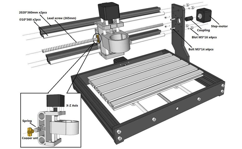
9, 7 Step4 X-Z Axis Assembly Installation Note: 1. First fix the coupling to the 42 stepper motor, and then fix the 42 stepper motor to the bakelite-C. 2. First fully insert the spring and brass nut into the Z-X axis assembly, and then tighten the X screw. Step5 Bakelite-D Installation
… -
19, CNC 3018-PRO 17 Click this button to start if use the computer control. Notice: speed and S value are different with material,it is recommended that the speed of engraving mode is 500~1000, the power is 500~800, the speed of cutting mode is 50~300, and the power is 900~1000. Tips: Enter «$32=1 in the control window ,It can be set to M4 laser mode for better engraving effect. 4.If you use offline controller, you can save the program as an «NC» file …
-
20, 18 Offline controller 1.Connect offline controller to computer via USB cable(can not connect offline controller line) Note: Use USB cable to transfer files, don’t insert SD card into card reader to transfer, it is easy to crash. 2.Copy the NC file to offline controller
… -
11, 9 Note: The screw M4*30mm here requires a 3mm hexagon wrench. When connecting the spindle motor cable, observe the direction of spindle rotation and turn clockwise to indicate that the connection is correct. Otherwise, change the connection position. Step7 Control Board Installation Note: only need to fix the screws in the upper row
… -
21, CNC 3018-PRO 19 3.Offline control connected to the control board Note: When using offline controller, you need to unplug the USB cable from the computer, because offline and computer cannot be used together. 4.Press the [X+/X-/Y+/Y-/Z+/Z-] key to move the spindle to the machine origin (tool setting method: the cutter just touches the object, press the [Exit] key), select the engraving file and click [ok ] Key to start carving 5.Interface introduction A.…
-
15, 13 Grblcontrol Use Toll setting Note: When performing knife setting, when the moving knife just touches the object, click «Zero xy» and
… -
18, 16 3.RASTER IMAGE IMPORT Raster import allows you to load an image of any kind in LaserGRBL and turn it GCode instructions without the need of other software. LaserGRBL supports photos, clip art, pencil drawings, logos, icons and try to do the best with any kind of image. It can be recalled from “File, Open File” menu by selecting an image of type jpg, png or bmp.
… -
16, 14 «Zero z», and finally click «Send». Getting Started After the machine is assembled, you can perform basic machine tests. The following is the recommended start up sequence for the system: 1.Confirm that the USB cable of the control board is plugged into your computer, and then start the computer. 2.Start the Candle software and verify in the status window that no errors are displayed. Under normal circumstances, when the control board is connected to the software, it will display «Idle». If a red erro…
-
3, 1 Parts list Serial number Name Type Qty Picture 1 working desk 15*180*300mm 1 2 Aluminum 20*40*290mm 2 3 Aluminum 20*20*290mm 2 4 X Linear guide Φ10*360mm 2 5 Y Linear guide Φ10*290mm 2 6 X screw T8(365mm) 2 7 Y screw T8(295mm) 2 8 Bakelite 1 9 Stepper motor 42*34mm 2 10 Spindle 775ER\100w\8000rmp 1 11 X Z-Parts 1 12 Y-Axis slider 10mm 4
… -
5, 3 4mm 1 25 Bolt M5*10mm 4 M5*16mm 43 M4*14mm 8 26 Copper Nut 2 27 T Nut M5*20 16 28 Slider Nut M5*30 10 29 Spring 0.8*12*30mm 2 30 Coupling& Set Screw 5*8mm 2 31 ER Wrench 13*87*2mm 1 17*88*2mm 1 32 Brush 1 33 Rolled Strip 1
… -
2, 1 Contents Parts list·························································1 Machine Installation·········································· 4 Grblcontrol····················································11 Getting Started··············································· 14 Lasergrbl·························�…
-
17, 15 Lasergrbl 1.Install lasergrbl software: Before installing the software, we have to install the CH340SER driver on the computer ,Then use the USB cable to connect to the computer (don’t plug it offline), open the Lasergrbl software (laser->Lasergrbl) and install . ● Console window print ” Grbl 1.1f [‘$’ for help] ” If the connection is successful. ●If the port selection is wrong, no information will be returned. 2.Turn on the laser, adjust the laser focus The laser will be turned on with low power mode…
-
13, 11 Grblcontrol 1 、 Install the driver(software->Drive->CH340SER.exe) Note: You need to exit the anti-virus software before installing the driver 2 、 Determine your Machine’s COM port: Windows XP: Right click on «My Computer», select «Properties», select «Device Manager». Windows 7: Click «Start» -> Right click «Computer» -> Select «Device Manager» -> «Ports (COM &…
-
8, 6 Step3 Base & Bakelite-C Installation Note: the distance between Bakelite-C and 2040 aluminum profile is 37.5mm, and Bakelite-C should be kept at 90 ° from the bottom Tips: First put the T-nut in the gap of 4040 aluminum profile, corresponding to the hole, and then tighten the screw Completed
… -
14, CNC 3018-PRO 12 3 、 Open GrblControl software(software -> Grblcontrol -> grblControl.exe) Tips: Right-click «Send to», select «Desktop Shortcut», and then you can open it directly on the desktop. ● Console window print ” [CTRL+X] < Grbl 1.1f [‘$’ for help]” If the connection is successful. ● Console window print ” Serial port error 1: No such file or directory “ indicate that the connection is failed.
… -
23, CNC 3018-PRO 21 Common Problem 1. What format files does the Grblcontrol(Candle) software support? Support Gcode files of nc, ncc, ngc, tap, txt 2.What file formats does the Lasergrbl software support? Support nc, cnc, tap, gcode, ngc, bmp, png, jpg, gif, svg 3.What should I do if the control board cannot be connected? Exit the software, unplug the wire, and reconnect it. Or update the firmware. 4.The X, y, and z axes of the machine cannot be moved, what should I do? First check whether the wires are correct…