

AVR 1700,AVR 170,AVR 170/230C
Audio/video receiver
Owner’s Manual
AVR
|
INTRODUCTION |
3 |
|
SUPPLIED ACCESSORIES |
3 |
|
IMPORTANT SAFETY INFORMATION |
3 |
|
PLACE THE AVR |
3 |
|
FRONT-PANEL CONTROLS |
4 |
|
REAR-PANEL CONNECTORS |
6 |
|
SYSTEM REMOTE CONTROL FUNCTIONS |
8 |
|
INTRODUCTION TO HOME THEATER |
10 |
|
TYPICAL HOME THEATER SYSTEM |
10 |
|
MULTICHANNEL AUDIO |
10 |
|
SURROUND MODES |
10 |
|
PLACE YOUR SPEAKERS |
10 |
|
PLACING THE LEFT, CENTER AND RIGHT SPEAKERS |
10 |
|
PLACING THE SURROUND SPEAKERS |
10 |
|
PLACING THE SUBWOOFER |
10 |
|
TYPES OF HOME THEATER SYSTEM CONNECTIONS |
11 |
|
SPEAKER CONNECTIONS |
11 |
|
SUBWOOFER CONNECTIONS |
11 |
|
SOURCE DEVICE CONNECTIONS |
11 |
|
VIDEO CONNECTIONS |
12 |
|
RADIO CONNECTIONS |
12 |
|
USB/iPod PORT |
12 |
|
MAKING CONNECTIONS |
13 |
|
CONNECT YOUR SPEAKERS |
13 |
|
CONNECT YOUR SUBWOOFER |
13 |
|
CONNECT YOUR TV OR VIDEO DISPLAY |
13 |
|
CONNECT YOUR AUDIO AND VIDEO SOURCE DEVICES |
13 |
|
CONNECT TO YOUR HOME NETWORK |
15 |
|
CONNECT THE RADIO ANTENNAS |
15 |
|
CONNECT IR EQUIPMENT |
15 |
|
CONNECT THE TRIGGER OUTPUT |
15 |
|
CONNECT TO AC POWER |
16 |
|
SET UP THE REMOTE CONTROL |
16 |
|
INSTALL THE BATTERIES IN THE REMOTE CONTROL |
16 |
|
PROGRAM THE REMOTE TO CONTROL YOUR SOURCE |
|
|
DEVICES AND TV |
16 |
Table of Contents
|
SET UP THE AVR |
17 |
|
TURN ON THE AVR |
17 |
|
USING THE ON-SCREEN MENU SYSTEM |
17 |
|
CONFIGURE THE AVR FOR YOUR SPEAKERS |
17 |
|
ASSIGN THE AVR INPUT CONNECTORS |
18 |
|
SET UP THE NETWORK |
18 |
|
ADDITIONAL SOURCE SETUP MENU ITEMS |
19 |
|
OPERATING YOUR AVR |
19 |
|
CONTROLLING THE VOLUME |
19 |
|
MUTING THE SOUND |
19 |
|
LISTENING THROUGH HEADPHONES |
19 |
|
SELECTING A SOURCE |
19 |
|
VIDEO TROUBLESHOOTING TIPS |
19 |
|
LISTENING TO FM AND AM RADIO |
20 |
|
LISTENING TO INTERNET RADIO (vTUNER) |
20 |
|
LISTENING TO AN iPod/iPhone/iPad DEVICE |
20 |
|
LISTENING TO MEDIA ON A USB DEVICE |
20 |
|
LISTENING TO MEDIA VIA YOUR HOME NETWORK |
21 |
|
LISTENING TO MEDIA VIA AIRPLAY |
22 |
|
SELECTING A SURROUND MODE |
22 |
|
ADVANCED FUNCTIONS |
23 |
|
AUDIO PROCESSING AND SURROUND SOUND |
23 |
|
MANUAL SPEAKER SETUP |
24 |
|
SYSTEM SETUP |
26 |
|
ADVANCED REMOTE CONTROL PROGRAMMING |
26 |
|
RECORDING |
27 |
|
SLEEP TIMER |
27 |
|
RESETTING THE REMOTE |
27 |
|
PROCESSOR RESET |
27 |
|
MEMORY |
27 |
|
TROUBLESHOOTING |
28 |
|
SPECIFICATIONS |
29 |
|
APPENDIX |
30 |
2
AVR
Introduction
Thank you for choosing this Harman Kardon® product!
For more than fifty years, the Harman Kardon mission has been to share a passion for music and entertainment, using leading-edge technology to achieve premium performance. Sidney Harman and Bernard Kardon invented the receiver, a single component designed to simplify home entertainment without compromising performance. Over the years, Harman Kardon products have become easier to use while offering more features and sounding better than ever.
The AVR 1700, AVR 170 and AVR 170/230C 5.1-channel digital audio/video receivers (AVRs) continue this tradition with some of the most advanced audio and video processing capabilities yet and a wealth of listening and viewing options.
To obtain the maximum enjoyment from your new AVR, please read this manual and refer back to it as you become more familiar with its features and their operation.
If you have any questions about this product, its installation or its operation, please contact your Harman Kardon retailer or custom installer, or visit our Web site at www. harmankardon.com.
Supplied Accessories
The following accessory items are supplied with your AVR. If any of these items are missing, please contact your Harman Kardon dealer, or Harman Kardon customer service at www.harmankardon.com.
ss3YSTEM REMOTEMCONTROL
ss%Z3ET %1™ microphone
ss!- LOOPLANTENNA
ss&- WIRE ANTENNA
ss4HREER!!!!BATTERIESR
ss!# POWERECORD
|
Introduction, Supplied Accessories, Important |
|
|
Safety Information and Place the AVR |
ENGLISH |
IMPORTANT SAFETY INFORMATION
Verify Line Voltage Before Use
The AVR 1700 has been designed for use with 120-volt alternating current (AC). The AVR 170 and AVR 170/230C have has been designed for use with 220 – 240-volt AC. Connection to a line voltage other than that for which your AVR is intended can create
AASAFETY ANDNlRERHAZARD ANDNMAYADAMAGE THEHUNIT )F YOUOHAVE ANY QUESTIONSTABOUTO the voltage requirements for your specific model or about the line voltage in your area, contact your selling dealer before plugging the unit into a wall outlet.
Do Not Use Extension Cords
4O AVOID SAFETY HAZARDS USESONLY THEHPOWERECORD SUPPLIED WITH YOUR UNIT 7EEDO NOTO recommend that extension cords be used with this product. As with all electrical devices, do not run power cords under rugs or carpets, or place heavy objects on them. Damaged
POWERECORDSRSHOULD BE REPLACED IMMEDIATELY BY AN AUTHORIZED SERVICE CENTER WITH AACORD meeting factory specifications.
Handle the AC Power Cord Gently
When disconnecting the power cord from an AC outlet, always pull the plug; never pull the cord. If you do not intend to use your AVR for any considerable length of time, disconnect the plug from the AC outlet.
Do Not Open the Cabinet
There are no user-serviceable components inside this product. Opening the cabinet may
PRESENTSAASHOCKOHAZARD ANDNANYYMODIlCATION TO THEHPRODUCTDWILL VOID YOUR WARRANTY )F water or any metal object such as a paper clip, wire or staple accidentally falls inside
THEHUNIT DISCONNECTOIT FROMCTHE !# POWERESOURCE IMMEDIATELY AND CONSULT ANSAUTHORIZED service center.
CATV or Antenna Grounding (AVR 1700)
If an outside antenna or cable system is connected to this product, be certain that it is grounded so as to provide some protection against voltage surges and static charges. Section 810 of the United States National Electrical Code, ANSI/NFPA No. 70-1984, provides information with respect to proper grounding of the mast and supporting
STRUCTURE GROUNDINGNOF THEHLEAD INDWIRE TO AN ANTENNAEDISCHARGEEUNIT SIZE OF GROUNDINGN conductors, location of antenna discharge unit, connection to grounding electrodes and requirements of the grounding electrode.
NOTE TO CATV SYSTEM INSTALLER: This reminder is provided to call the CATV (cable TV) system installer’s attention to article 820-40 of the NEC, which provides guidelines for proper grounding and, in particular, specifies that the cable ground shall be connected to the grounding system of the building, as close to the point of cable entry as possible.
Place the AVR
ss0LACEATHEH!62 ON AAlRMRANDNLEVELVSURFACE «E CERTAINTTHATTTHEESURFACEFANDNANYYMOUNTING hardware can support the AVR’s weight.
ss0ROVIDEV PROPER SPACEA ABOVEO ANDN BELOWW THEH !62 FORO VENTILATION 2ECOMMENDEDM clearance distances are 30cm above the unit, 30cm behind the unit and 30cm on each side of the unit.
ss)F YOU INSTALL THE !62 IN AACABINETBOR OTHER ENCLOSEDSAREA PROVIDEVCOOLING AIROWITHIN THE cabinet. Under some circumstances, a fan may be required.
ss$O NOTOOBSTRUCT THEHVENTILATION SLOTSOON THEHTOPOOF THEH!62 OR PLACEAOBJECTSEDIRECTLY over them.
ss$O NOT PLACE THE !62 DIRECTLYRON A CARPETEDOSURFACE
ss$O NOT PLACE THE !62 IN MOIST OR HUMID LOCATIONS INIEXTREMELY HOT OROCOLD LOCATIONS INI areas near heaters or heat registers, or in direct sunlight.
3
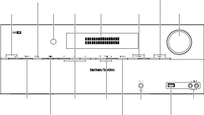
Front-Panel Controls
|
Channel |
Source Select |
||||
|
Level Control |
|||||
|
Buttons |
|||||
|
Button |
|||||
|
Power Indicator/ |
IR |
Set |
Message |
Surround Mode |
Volume |
|
Power Button |
Sensor |
Button |
Display |
Select Buttons |
Knob |
|
Tuning Mode Button/ |
Left/Right |
Up/Down Buttons/ |
Headphone Jack/ |
Aux Analog |
|
RDS Button |
Buttons |
Tuning Buttons |
%Z3ET %1 -IC |
Audio Input |
|
Connector |
Connector |
|||
|
Digital Input |
Surround-Mode |
USB Port |
||
|
Button |
Category Button |
4
AVR
Front-Panel Controls, continued
Power indicator/Power button: The AVR has four different power modes:
ssOff (Power indicator not illuminated): When the rear-panel Main Power switch is in the Off position or the power cord is unplugged the AVR is off and will not respond to any commands. Plugging the power cord into a live AC outlet and setting the Main Power switch in the On position will put the AVR into the Eco Standby mode.
ssEco Standby (Power indicator glows solid amber): 4HEH%COC3TANDBYNMODE MINIMIZESM energy consumption when you’re not using the AVR. When the AVR is in Eco Standby, it will not automatically turn on or play audio in response to an AirPlay signal from a networked device. When the AVR is in Eco Standby, pressing the Power button turns it on. To put the AVR into Eco Standby when it is on, press the Power button for more than three seconds. NOTE: The AVR will not automatically enter the Eco Standby mode.
ssStandby (Power indicator glows solid amber): The Standby mode mutes the AVR and shuts off its front-panel display, but allows the AVR to automatically turn on and play audio in response to an AirPlay signal from a networked device. See Listening to Media via AirPlay, on page 22, for more information. When the AVR is in Standby, pressing the Power button turns it on. To put the AVR into Standby when it is on, press the Power button for less than three seconds. NOTE: The AVR will automatically enter the Standby mode whenever no control buttons have been pressed and no audio signal has been present for 30 minutes.
ssOn (Power indicator glows solid white): When the AVR is on it is fully operational.
IMPORTANT NOTE: If the PROTECT message ever appears on the AVR’s frontpanel Message display, turn off the AVR and unplug it from the AC outlet. Check all speaker wires for a possible short circuit (the “+” and “–” conductors touching each other or both touching the same piece of metal). If a short circuit is not found, bring the unit to an authorized Harman Kardon service center for inspection and repair before using it again.
Tuning Mode button (AVR 1700 only): This button toggles between manual (one frequency step at a time) and automatic (seeks frequencies with acceptable signal strength) tuning mode. It also toggles between stereo and mono modes when an FM station is tuned in.
RDS button (AVR 170 only): When listening to an FM radio station that broadcasts RDS information, this button activates the various RDS functions. NOTE: RDS service may not be available in all areas.
Channel Level Control button: Press this button to activate the channel-level adjustment feature. After pressing this button, use the Up/Down buttons to select the channel for adjustment and use the Left/Right buttons to adjust the channel’s level.
Digital Input button: Press this button to change the audio input for the current source. Use the Left/Right buttons to cycle through the available input connections, and press the Set button to assign the currently-displayed connection to the source.
Front-Panel Controls, continued
IR sensor: This sensor receives infrared (IR) commands from the remote control. It is important to ensure that the sensor is not blocked.
Set button: Press this button to select the currently highlighted menu item.
Left/Right buttons: Use these buttons to navigate the AVR’s menus.
Message display: Various messages appear in this two-line display in response to commands and changes in the incoming signal. In normal operation, the current source name appears on the upper line, while the surround mode is displayed on the lower line. When the on-screen display menu system (OSD) is in use, the current menu settings appear.
Up/Down buttons/Tuning buttons: Use these buttons to navigate the AVR’s menus. When the radio is the active source, use these buttons to tune stations according to the setting of the Tuning Mode button (see above).
Surround-Mode Category button: Press this button to select a surround-sound category. Each press changes the surround-mode category: Auto Select, Virtual, Stereo, Movie, Music and Video Game. To change the specific surround-sound mode within the category, use the Surround Mode Select buttons. See Audio Processing and Surround Sound, on page 23, for more information on surround modes.
Surround-Mode Select buttons: After you have selected the desired surround-mode category, press these buttons to select a specific mode within the category, such as to change from Dolby® Pro Logic® II Movie mode to Logic 7® Movie mode. Surround-mode availability depends on the nature of the source input signal, i.e., digital versus analog, and the number of channels encoded within the signal.
Source Select buttons: Press these buttons to select the active source.
Headphone jack/EzSet/EQ Mic connector: Connect a 1/4″ stereo headphone plug to this jack for private listening. This jack is also used to connect the supplied microphone
FORO THEH %Z3ET %1 PROCEDUREE DESCRIBEDR IN Configure the AVR for Your Speakers, on page 17.
USB port: The USB port can be used to play audio files from an Apple iOS® device connected to the port, and can also be used to play MP3 and WMA audio files from a USB device inserted into the port. Insert the connector or device into the USB port oriented so it fits all the way into the port. You may insert or remove the connector or device at any time — there is no installation or ejection procedure.
You can also use the USB port to perform firmware upgrades. If an upgrade for the AVR’s operating system is released in the future, you will be able to download it to the AVR using this port. Complete instructions will be provided at that time.
IMPORTANT: Do not connect a PC or other USB host/controller to this port, or you may damage both the AVR and the other device. HDD is not supported.
Volume knob: Turn this knob to raise or lower the volume.
Aux Analog Audio Input connector: Connect an auxiliary source component that will be used only temporarily, such as a camcorder, portable music player or game console, here.
ENGLISH
5

AVR
Rear-Panel Connectors
Rear-Panel Connectors
|
Network |
HDMI Monitor Out |
Digital Audio |
|||
|
Connector |
Input Connectors |
||||
|
Connector |
|||||
|
Radio Antenna |
HDMI Input |
RS-232 |
|||
|
Connector |
|||||
|
Connectors |
Connectors |
||||
|
Analog Audio |
IR In & |
Composite |
Main Power |
AC Input |
|
|
Input/Output |
Trigger Out |
Video Input |
Switch |
Connector |
|
|
Connectors |
Connectors |
Connectors |
|||
|
Subwoofer |
Speaker |
Composite Video |
|||
|
Connector |
Connectors |
Monitor Output |
|||
|
Connectors |
6

AVR
Rear-Panel Connectors, continued
ENGLISH
Rear-Panel Connectors, continued
Radio Antenna connectors: Connect the included AM and FM antennas to their respective terminals for radio reception.
Analog Audio Input/Output connectors: Use the AVR’s Analog Audio Input/Output connectors for source devices that don’t have HDMI or digital audio connectors. Use the Rec Out connectors to connect to the audio inputs of a VCR or tape deck. See Connect Your Audio and Video Source Devices, on page 13, for more information.
Network connector: Use a Cat. 5 or Cat. 5E cable (not supplied) to connect the AVR’s Network connector to your home network to enjoy Internet radio and content from DLNAcompatible devices that are joined to the network. See Connect to Your Home Network, on page 15, for more information.
Subwoofer connector: Connect this jack to a powered subwoofer with a line-level input. See Connect Your Subwoofer, on page 13, for more information.
IR In and Trigger Out connectors: When the IR sensor on the front panel is blocked (such as when the AVR is installed inside a cabinet), connect an optional IR receiver to the IR In jack. The Trigger Out connector provides 12V DC whenever the AVR is on. Connect it to the trigger input of a device such as a powered subwoofer.
Speaker connectors: Use two-conductor speaker wire to connect each set of terminals to the correct speaker. See Connect Your Speakers, on page 13, for more information.
HDMI® Input connectors: The HDMI (High-Definition Multimedia Interface) feature is a connection for transmitting digital audio and video signals between devices. If your source devices have HDMI connectors, using them will provide the best possible video and audio performance quality. Since the HDMI cable carries both digital video and digital audio signals, you do not have to make any additional audio connections for devices you connect via HDMI connections. See Connect Your Audio and Video Source Devices, on page 13, for more information.
HDMI Monitor Out connector: If your TV has an HDMI connector and you have HDMI source devices, use an HDMI cable (not included) to connect it to the AVR’s HDMI Monitor Out connector.
Notes on using the HDMI Monitor Out connector:
ss7HEN CONNECTING AA$6) EQUIPPED DISPLAYPTO THEH($-) -ONITORI/UT CONNECTOR USES an HDMI-to-DVI adapter and make a separate audio connection.
ss-AKE SURE THEH($-) EQUIPPEDQDISPLAYPIS ($#0 COMPLIANT )F IT ISN T DO NOTOCONNECTN it via HDMI; use a composite analog video connection instead and make a separate audio connection.
Composite Video Input connectors: Use composite video connectors for video source devices that don’t have HDMI or component video connectors. You will also need to make an audio connection from the source device to the AVR. See Connect Your Audio and Video Source Devices, on page 13, for more information.
Composite Video Monitor Output connector: If your TV or video display does not have an HDMI connector, or if your TV does have an HDMI connector but you are connecting some source devices with only composite video connectors, use a composite video cable (not included) to connect the AVR’s Composite Video Monitor Out connector to your TV’s composite video input connector.
Digital Audio Input connectors: If your non-HDMI source devices have digital outputs, connect them to the AVR’s digital audio connectors. NOTE: Make only one type of digital connection (HDMI, optical or coaxial) from each device. See Connect Your Audio and Video Source Devices, on page 13, for more information.
RS-232 connector: This connector is used to connect to external control hardware. Consult a certified professional installer for more information.
Main Power switch: This mechanical switch turns the AVR’s power supply on or off. It is usually left on and cannot be turned on or off using the remote control.
AC Input connector: After you have made all other connections, plug the supplied AC power cord into this receptacle and into an unswitched wall outlet.
7

AVR
System Remote Control Functions
IR Transmitter Lens
Program Indicator LED
Power On Button
Power Off Button
AVR Button
Test Tone Button
Channel Up/Down Buttons
Tone Controls Button
Back Button
OSD Button
Direct Station Entry Button
Memory Button
Tuning Up/Down Buttons
Night Mode Button
Track Skip Up/Down Buttons
System Remote Control Functions
Mute Button
Source Selector Buttons
Channel Volume Adjust Button
Volume Up/Down Buttons
Delay Adjust Button
Options Button
 OK Button
Sleep Button
Left/Right/Up/Down Buttons
Number Buttons
Clear Button
Tuning Mode Button
Preset Station Up/Down Buttons
Disc Skip Button (AVR 1700)
RDS Button (AVR 170)
Macro Buttons
Display Dimmer Button
Transport Control Buttons
8

AVR
System Remote Control Functions, continued
In addition to controlling the AVR, the AVR remote is capable of controlling five other devices, plus your TV and an iPod/iPhone that is docked in the AVR’s front-panel USB port. During the installation process, you may program the codes for each of your source components into the remote. (See Program the Remote to Control Your Source Devices and TV, on page 16, for programming information.) To operate a component, press its Source Selector button to change the remote’s control mode.
A button’s function depends on which component is being controlled. See Table A9 in the Appendix for listings of the functions for each type of component. Most of the buttons on the remote have dedicated functions, although the precise codes transmitted vary depending on the specific device being controlled. Due to the wide variety of functions for various source devices, we have included only a few of the most often-used functions on the remote: alphanumeric keys, transport controls, television-channel control, menu access and power on and off. To return the remote to the AVR control mode at any time, press the AVR button.
IR Transmitter lens: As buttons are pressed on the remote, infrared codes are emitted through this lens.
Program Indicator LED: This LED lights up to indicate various procedures when the remote is in the Programming mode.
Power On/Off buttons: Press these buttons to turn the AVR or the device being controlled on and off. The Main Power switch on the AVR’s rear panel must be on for this button to turn the AVR on and off.
NOTE: When the AVR is on, pressing the Power Off button for more than three seconds will put it into the Eco Standby mode. See Power indicator/Power button, on page 5 for more information.
Mute button: Press this button to mute the AVR’s speaker-output connectors and Headphone jack. To restore the sound, press this button or adjust the volume.
AVR button: Press this button to switch the remote’s control mode to operate the AVR.
Source Selector buttons: Press one of these buttons to select a source device, e.g., cable/satellite tuner, radio, etc. This action will also turn on the AVR and switch the remote’s control mode to operate the selected source device.
ss4HEHlRST PRESSEOF THEH2ADIOD3OURCE 3ELECTOR BUTTON SWITCHESCTHEH!62 TO THEHLAST USED tuner band (AM or FM). Each successive press changes the band.
ss4HEHlRST PRESSEOF THEH53″3BUTTON SWITCHESCTHEH!62 TO THEHLAST USED SOURCE 53″ OR iPod). Each successive press cycles between the two sourcee.
ss4HEHlRST PRESSEOF THEH.ETWORKWBUTTON SWITCHESCTHEH!62 TO THE LAST USED SOURCE .ETWORK or vTuner). Each successive press cycles between the two sources.
Test Tone button: Press this button to activate the test tone for calibrating channel volume levels by ear.
Channel Volume Adjust button: Press this button to activate the individual channellevel adjustment. It lets you easily change the channel balance to suit different programs or seating arrangements. See Manual Speaker Setup, on page 24, for more information.
Channel Up/Down buttons: The Channel Up/Down buttons have no effect on the AVR but are used to change channels on TVs and some video sources.
Volume Up/Down buttons: Press these buttons to raise or lower the volume.
Tone Controls button: Press this button to access the bass and treble controls. Use the OK button to select an adjustment and use the Up/Down buttons to change the settings.
Delay Adjust button: Pressing this button lets you adjust two different types of delay settings (use the Up/Down buttons to cycle through the settings):
ss! 6 3YNC 4HIS SETTINGTLETS YOUORESYNCHRONIZEHTHEHAUDIODANDNVIDEODSIGNALSNFROM AASOURCE to eliminate a “lip sync” problem. Lip-sync issues can occur when the video portion of a signal undergoes additional processing in either the source device or the video display. Use the Left/Right buttons to delay the audio by up to 180ms.
ss&RONT , #ENTER &RONT 2 3URR 2 3URR , 3UBWOOFER 4HESEESETTINGS LETEYOUOSETETHEHDELAYLFORO each speaker to compensate for the different distances they may be from the listening position. Use the Up/Down buttons to cycle through each of the system’s speakers, and use the Left/Right buttons to set the distance each speaker is from the listening position. See Manual Speaker Setup, on page 24, for more information.
|
System Remote Control Functions, continued |
ENGLISH |
Back button: Press this button to return to the previous menu screen when you’re using the on-screen menu (OSD) system.
Options button: This button allows you to adjust playback and various other options for the AVR’s built-in sources and when controlling other components.
OSD button: Press this button to activate the on-screen display menu system.
OK button: This button is used to select items from the menu system.
Sleep button: Press this button to activate the sleep timer, which turns off the AVR after a programmed period of time (up to 90 minutes).
Left/Right/Up/Down buttons: These buttons are used to navigate the menu system.
Number buttons: Use these buttons to enter numbers for radio-station frequencies or to select station presets.
Direct Station Entry button: Press this button before using the Number buttons to enter a radio station frequency.
Clear button: Press this button to clear a radio station frequency you have started to enter.
Memory button: To save the currently tuned radio station as a preset, press this button, then a Number button.
Tuning Mode button: Press this button to toggle the radio between manual (one frequency step at a time) and automatic (seeks frequencies with acceptable signal strength) tuning mode. It also toggles between stereo and mono modes when an FM station is tuned in.
Tuning Up/Down buttons: Press these buttons to tune a radio station. Depending on whether the tuning mode has been set to manual or automatic, each press will either change one tuning frequency increment at a time or seek the next higher or lower station with acceptable signal strength.
Preset Station Up/Down buttons: Press these buttons to cycle through your preset radio stations.
Night Mode button: Press this button to activate Night mode with specially encoded Dolby Digital discs or broadcasts. Night mode compresses the audio so that louder passages are reduced in volume to avoid disturbing others, while dialogue remains intelligible. Each press of the button advances through the following settings:
ss/FF .O COMPRESSIONEIS APPLIED ,OUD PASSAGESEIN THEHPROGRAM REMAIN AS THEY WERE recorded.
ss-ID ,OUDOPASSAGESEIN THE PROGRAM ARE REDUCED MODERATELY INYVOLUME
ss-AX ,OUDOPASSAGESEIN THE PROGRAM ARE REDUCED MOREMIN VOLUME
Disc Skip button (AVR 1700): This button is used with some optical disc changers to skip to the next disc.
RDS button (AVR 170): When listening to an FM radio station that broadcasts RDS information, this button activates the various RDS functions.
Macro buttons: These buttons may be programmed to execute a series of up to 19 commands with a single button press. They are useful for programming the command
TO TURN ON OR OFFFALLLOF YOUR COMPONENTS OR FOROACCESSINGSSPECIALIZED FUNCTIONSTFOROAA different component from the one that you are currently operating. See Programming Macro Commands, on page 27, for information about programming macros.
Track Skip Up/Down buttons: These buttons are used with the AVR’s built-in sources (USB, iPod, Network, AirPlay, etc) and many source components to change tracks or chapters.
Display Dimmer button: Press this button to dim the AVR’s front-panel display partially or fully.
Transport Control buttons: These buttons have no effect on the AVR but are used to control many source components. By default, when the remote is operating the AVR, these buttons will control a Harman Kardon Blu-ray Disc™ player or DVD player.
9

AVR
Introduction to Home Theater and Place Your Speakers
Introduction to Home Theater
4HIS INTRODUCTORYYSECTIONTWILL HELP YOUOTO FAMILIARIZEIYOURSELF WITH SOME BASICSCONCEPTS unique to multichannel surround-sound AVRs, which will make it easier for you to set up and operate your AVR.
Typical Home Theater System
A home theater typically includes an audio/video receiver (AVR), which controls the system and supplies amplification for the loudspeakers; a disc player; a source component for television broadcasts (cable box, satellite dish AVR, HDTV tuner or antenna connected to the TV); a TV or video display; and multiple loudspeakers.
Multichannel Audio
The main benefit of a home theater system is its ability to produce “surround sound.” Surround sound uses multiple speakers and amplifier channels to immerse you in the audio/video presentation for a dramatically increased sense of realism.
Your AVR can have up to five main speakers connected directly to it, plus a subwoofer. Each main speaker is powered by its own amplifier channel inside the AVR. A system with more than two speakers is called a multichannel system. The different main speaker types in a home theater system are:
ss&RONTO,EFT ANDN2IGHT The front left and right speakers are used as in a 2-channel system. In many surround-sound modes, these speakers are secondary, while the main action, especially dialogue, is reproduced by the center speaker.
ss#ENTER TWhen you are watching movies and television programs, the center speaker reproduces most of the dialogue and other soundtrack information that occurs on the screen, anchoring it with the picture. When you are listening to a musical program, the center speaker helps to create a seamless front soundstage, creating a more realistic “you-are-there” listening experience.
ss3URROUND ,EFT ANDN2IGHT The surround left and right speakers produce ambient sounds that help create a realistic and immersive surround-sound environment. They als o help recreate directional sound effects such as aircraft flyovers.
Many people expect the surround speakers to play as loudly as the front speakers. Although you will calibrate all of the speakers in your system to sound equally loud at the listening position, most artists use the surround speakers for ambient effects only, and they create their programs to steer relatively little sound to these speakers.
ss3UBWOOFER A subwoofer is designed to play only the lowest frequencies (the deep bass). It augments smaller, limited-range main speakers that are usually used for the other channels. Many digital-format programs, such as movies recorded in Dolby Digital, contain a low-frequency effects (LFE) channel that is directed to the subwoofer. The LFE channel packs the punch of a rumbling train or airplane, or the power of an explosion, adding realism and excitement to your home theater. Some people use two subwoofers for additional power and for even distribution of the sound.
Surround Modes
There are different theories as to the best way to present surround sound and to distribute the individual channel information to the surround-sound system’s speakers. A variety of algorithms have been developed in an effort to recreate the way we hear sounds in the real world, resulting in a rich variety of options. Several companies have developed different surround-sound technologies, all of which can be accurately reproduced by your AVR:
ss$OLBYL,ABORATORIES TDolby TrueHD, Dolby Digital Plus, Dolby Digital, Dolby Digital EX, Dolby Pro Logic II.
ss$43 DTS-HD™ High Resolution Audio, DTS-HD Master Audio™, DTS, DTS 96/24™ DTS NEO: 6™.
ss(!2-!. )NTERNATIONAL ELogic 7, virtual speaker.
ss3TEREO -ODES 2-channel stereo and 5-channel stereo.
Appendix Table A8, on page 32, contains detailed explanations of the different surroundsound options available on your AVR. Digital surround-sound modes, such as Dolby Digital and DTS systems, are available only with specially encoded programs, such as those available via HDTV, DVD and Blu-ray Disc media and digital cable or satellite television. Other surround modes may be used with digital and analog signals to create a different surround presentation or to use a different number of speakers. Surround-mode selection depends upon the number of speakers in your system, the programs you are watching or listening to, and your personal tastes.
Place Your Speakers
Determine the locations for your system’s speakers according to their manufacturer’s directions and the layout of your listening room. Use the illustration below as a guide for 5.1-channel systems.
To create the most realistic surround-sound environment possible, you should place your speakers in a circle with the listening position at its center. You should angle each speaker so it directly faces the listening position. Use the diagram below as a guide.
Placing the Left, Center and Right Speakers
Place the center speaker either on top of, below or mounted on the wall above or below the TV or video-display screen. Place the front left and right speakers along the circle, about 30 degrees from the center speaker and angled toward the listener.
Place the front left, front right and center speakers at the same height, preferably at about the same height as the listener’s ears. The center speaker should be no more than 2 feet (0.6m) above or below the left/right speakers. If you’re using only two speakers with your AVR, place them in the front left and front right positions.
Placing the Surround Speakers
You should place the left and right surround speakers approximately 110 degrees from the center speaker, slightly behind and angled toward the listener. Alternatively, you can place them behind the listener, with each surround speaker facing the opposite-side front speaker. You should place the surround speakers 2 feet – 6 feet (0.6m – 1.8m) higher than the listener’s ears.
NOTE: Your AVR will sound its best when the same model or brand of loudspeaker is used for all positions.
Placing the Subwoofer
Because a room’s shape and volume can have a dramatic effect on a subwoofer’s performance, it is best to experiment with placement so that you will find the location that produces the best results in your particular listening room. With that in mind, these rules will help you get started:
ss0LACINGCTHEHSUBWOOFERONEXT TO AAWALL GENERALLYRWILL INCREASE THEHAMOUNT OF BASS IN THEH room.
ss0LACINGCTHEHSUBWOOFEROIN AACORNER GENERALLYRWILL MAXIMIZE THEEAMOUNT OF BASS IN THEH room.
ss)N MANYYROOMS PLACINGCTHEHSUBWOOFEROALONGOTHEHSAME PLANEAAS THEHLEFT ANDNRIGHTG speakers can produce the best integration between the sound of the subwoofer and that of the left and right speakers.
ss)N SOME ROOMS THEHBEST PERFORMANCERCOULDUEVEN RESULT FROM PLACING THEHSUBWOOFERO behind the listening position.
A good way to determine the best location for the subwoofer is by temporarily placing it in the listening position and playing music with strong bass content. Move around to various locations in the room while the system is playing (putting your ears where the subwoofer would be placed), and listen until you find the location where the bass performance is best. Place the subwoofer in that location.
10

AVR
Types of Home Theater
System Connections
ENGLISH
Types of Home Theater System Connections
There are different types of audio and video connections used to connect the AVR to your speakers, your TV or video display, and your source devices. The Consumer Electronics Association has established the CEA® color-coding standard.
Connection Color Guide Table
|
Analog Audio Connection |
Color |
|
Front Left/Right |
White/Red |
|
Center |
Green |
|
Surround Left/Right |
Blue/Gray |
|
Subwoofer |
Purple |
|
Digital Audio Connection |
Color |
|
Coaxial |
Orange |
|
Optical |
Black |
|
Analog Video Connection |
Color |
|
Composite Video |
Yellow |
Speaker Connections
Speaker cables carry an amplified signal from the AVR’s speaker terminals to each loudspeaker. Each cable contains two wire conductors, or leads, that are differentiated in some way, such as with colors or stripes.
The differentiation helps you maintain proper polarity, without which your system’s lowfrequency performance can suffer. Each speaker is connected to the AVR’s speakeroutput terminals using two wires, one positive (+) and one negative (–). Always connect the positive terminal on the speaker, which is usually colored red, to the positive terminal on the AVR, which is colored as indicated in the Connection Color Guide Table, above. The negative terminals on the speakers and the AVR are black.
Your AVR uses binding-post speaker terminals that can accept bare-wire cables or banana plugs. Bare-wire cables are installed as shown below:
|
1. Unscrew Cap |
2. Insert Bare Wire |
3. Tighten Cap |
Banana plugs are inserted into the hole in the middle of the terminal cap, as shown below:
|
A. Tighten Cap |
B. Insert Banana Connector |
|
into Hole in Cap |
Subwoofer Connections
The subwoofer is a speaker dedicated to reproducing only the low (bass) frequencies, which require more power. To obtain the best results, most speaker manufacturers offer powered subwoofers that contain their own amplifiers. Use a single RCA audio cable (not included) to make a line-level (non-amplified) connection from the AVR’s Subwoofer connector to a corresponding input jack on the subwoofer.
Although the AVR’s purple subwoofer output looks similar to a full-range analog audio jack, it is filtered so that only the low frequencies pass through it. Don’t connect this output to any device other than a subwoofer.
Source Device Connections
Audio and video signals originate in source devices (components where a playback signal originates) such as your Blu-ray Disc or DVD player, CD player, DVR (digital video recorder) or other recorder, tape deck, game console, cable or satellite television tuner, or a device docked in the AVR’s USB port. The AVR’s FM/AM tuner also counts as a source, even though no external connectors are needed other than the AVR’s FM and AM antennas. Separate connectors are required for the audio and video portions of the source device’s signal, except for digital HDMI connectors. The types of connectors you use will depend upon the capabilities of the source device and of your TV or video display.
Digital Audio Connections – HDMI
There are two types of audio connections – digital and analog. Digital audio signals are required for listening to sources encoded with digital surround modes, such as Dolby Digital and DTS, or for uncompressed PCM digital audio. Your AVR has three types of digital audio connectors: HDMI, coaxial and optical. Do not use more than one type of digital audio connector for each source device. However, it’s okay to make both analog and digital audio connections to the same source.
Your AVR is equipped with four rear-panel HDMI input connectors and one HDMI monitor output connector. HDMI technology enables digital audio and video information to be carried using a single cable, delivering the highest quality picture and sound. If your TV or video-display device has an HDMI input connector, make a single HDMI connection from each source device to the AVR.
The AVR’s HDMI Monitor Output connector contains an Audio Return Channel (ARC) that carries a digital audio signal from your TV or video display back to the AVR. It allows you to listen to HDMI devices that are connected directly to your TV (such as an Internet connection) without making an additional connection from the device to the AVR. The ARC signal is active when the TV source is selected. See System Setup, on page 26, for more information.
The HDMI connector is shaped for easy plug-in (see illustration, below), and HDMI cable runs are limited to about 10 feet (3m). If your video display has a DVI input and is HDCP-compliant, use an HDMI-to-DVI adapter (not included), and make a separate audio connection.
Always connect the colored (+) terminal on the AVR to the (+) terminal on the speaker (usually red), and the black (–) terminal on the AVR to the (–) terminal on the speaker (usually black).
IMPORTANT: Make sure the ( + ) and ( – ) bare wires do not touch each other or the other terminal. Touching wires can cause a short circuit that can damage your AVR or amplifier.
Digital Audio Connections – Coaxial
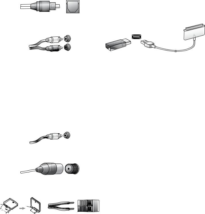
Coaxial digital audio jacks are usually color-coded orange. Although they look like standard RCA-type analog jacks, you should not connect coaxial digital audio outputs to analog inputs or vice versa.
11
AVR
Types of Home Theater System
Connections, continued
Digital Audio Connections – Optical
Optical digital audio connectors are normally covered by a shutter to protect them from dust. The shutter opens as the cable is inserted. Optical input connectors are color-coded using a black shutter.
Analog Audio Connections
Two-channel analog connections require a stereo audio cable, with one connector for the left channel (white) and one for the right channel (red). These two connectors are attached to each other.
For source devices that have both digital and analog audio outputs, you may make both connections.
Video Connections
Many source devices output both audio and video signals (e.g., Blu-ray Disc, DVD player, cable television box, HDTV tuner, satellite box, VCR, DVR). In addition to an audio connection as described above, make a video connection for each of these source devices. Make only one type of video connection for each device.
Digital Video Connections
If you have already connected a source device to one of the AVR’s HDMI input connectors, you have automatically made a video connection for that device, since the HDMI cable carries both digital audio and digital video signals.
Analog Video Connections – Composite Video
Composite video is the basic connection most commonly available. Both the chrominance (color) and the luminance (intensity) components of the video signal are transmitted using a single cable. The jack is usually color-coded yellow and looks like an analog audio jack. Do not connect a composite video jack to an analog audio or coaxial digital audio jack, or vice versa.
USB Port
The AVR can play audio files from an Apple iOS® device connected to the USB port, and allows you to control the iOS device via the AVR remote control. The AVR can also play MP3 and WMA audio files from a USB device inserted into the USB port. Insert the connector or device into the USB port oriented so it fits all the way into the port. You may insert or remove the connector or device at any time – there is no installation or ejection procedure.
The USB port on your AVR is also used to perform firmware upgrades. If an upgrade for the AVR’s operating system is released in the future, you will be able to download it to the AVR using this port. Complete instructions will be provided at that time.
IMPORTANT: Do not connect a PC or other USB host/controller to the AVR’s USB port, or you may damage both the AVR and the other device. HDD is not supported.
Radio Connections
Your AVR uses separate terminals for the included FM and AM antennas. The FM antenna uses a 75-ohm F-connector.
The AM antenna connector uses spring-clip terminals. After assembling the antenna as shown below, press the levers to open the connectors, insert the bare wires into the
OPENINGS ANDNRELEASEETHEHLEVERS TO SECURE THEHWIRES 4HEHANTENNA WIRESRARERNOTOPOLARIZED so you can insert either wire into either connector.
12

AVR
Making Connections
CAUTION: Before making any connections to the AVR, ensure that the AVR’s AC cord is unplugged from the AVR and the AC outlet. Making connections with the AVR plugged in and turned on could damage the speakers.
Connect Your Speakers
After you have placed your loudspeakers in the room as explained in Place Your Speakers, on page 10, connect each speaker to its color-coded terminal on the AVR as explained in Speaker Connections, on page 11. Connect the speakers as shown in the illustration.
Making Connections
Connect Your TV or Video Display
HDMI Monitor Out connector
If your TV has an HDMI connector and you have HDMI or component video source devices, use an HDMI cable (not included) to connect your TV to the AVR’s HDMI Monitor Out connector. It will provide the best possible picture quality.
|
AVR HDMI |
|
|
Monitor Out |
|
|
Connector |
TV |
|
HDMI Cable |
|
|
(not supplied) |
ENGLISH
Connect Your Subwoofer
Use a single RCA audio cable to connect the AVR’s Subwoofer Pre-Out connector to your subwoofer. Consult your subwoofer’s user manual for specific information about making connections to it.
|
Receiver |
|
|
Subwoofer |
Powered |
|
Connector |
Subwoofer |
|
Single |
|
|
RCA Audio Cable |
|
|
(not supplied) |
Composite Video Monitor Out connector
If your TV does not have an HDMI connector, or if your TV does have an HDMI connector but you are connecting some source devices with only composite video connectors, use a composite video cable (not included) to connect the AVR’s Composite Monitor Out connector to your TV’s composite video connector.
|
AVR Composite |
TV |
|
|
Monitor Out |
||
|
Connector |
Composite Video Cable
(not supplied)
Connect Your Audio and Video Source Devices
Source devices are components where a playback signal originates, e.g. a Blu-ray Disc or DVD player; a cable, satellite or HDTV tuner; etc. Your AVR has several different types of input connectors for your audio and video source devices: HDMI, composite video, optical digital audio, coaxial digital audio and analog audio.
Your AVR’s various Source Selector buttons have default assignments to different input connectors (listed in the “Default AVR Input Connector” column of the table below). For ease of setup and remote control programming, you should connect each source device to the connector where the corresponding default source button is assigned (e.g., connect your Cable/Satellite tuner box to HDMI 1).
However, you can connect your source devices as you wish and re-assign any of the video and audio input connectors to any of the Source Selector buttons listed in the table according to where you actually connect each of your source devices.
As you connect your various source components, fill out the “Connected Device” and “Assigned AVR Input Connector(s)” columns in the table – it will make it easier for you to assign the connectors to the Source Selector buttons after you have completed making all of the connections. (You will make any changes to the connector assignments later in the setup process.)
|
Source Selector |
Default AVR Input |
Connected |
Assigned AVR Input |
|
|
Button |
Connector |
Device |
Connector(s) |
|
|
Video |
Audio |
|||
|
Cable/Sat |
HDMI 1 |
|||
|
TV |
HDMI ARC |
|||
|
Disc |
HDMI 2 |
|||
|
Server |
HDMI 3 |
|||
|
Aux |
COMP. VID. 1/AUX AUDIO |
|||
|
Game |
HDMI 5 |
|||
|
STB |
HDMI 6 |
|||
|
Audio |
ANALOG AUDIO 2 |
|||
|
Network |
NETWORK |
Home Network |
–––– |
–––– |
Input Connections and Source Buttons
13

AVR
Making Connections, continued
HDMI devices
If any of your source devices have HDMI connectors, using those connectors will provide the best possible video and audio performance quality. Since the HDMI cable carries both digital video and digital audio signals, you do not have to make any additional audio connections for devices you connect via HDMI cables.
If you have a TV or other source device equipped with the HDMI Audio Return Channel function, you can feed its sound to the AVR via the HDMI Monitor Out connector’s Audio Return Channel, and it will not require additional audio connections to the AVR.
AVR
HDMI Connectors
HDMI Cable (not supplied)
To HDMI
Output
HDMI-Equipped Source Device
Composite video devices
Use composite video connectors for video source devices that don’t have HDMI connectors. You will also need to make an audio connection from the source device to the AVR.
AVR Component
Video Connectors
Composite Video
Cable (not supplied)
To Composite
 Video Output
Composite Video-Equipped
Source Device
14
Optical digital audio devices
If your non-HDMI source devices have optical digital outputs, connect them to the AVR’s Optical Digital Audio connectors. NOTE: Make only one type of digital connection (HDMI, optical or coaxial) from each device.
NOTE: Be sure to remove the caps from the tips of the optical cable before inserting them into the AVR and your source device.
|
AVR Digital Audio |
Remove Caps |
|||||
|
Connectors |
||||||
Optical Digital Audio
Cable (not supplied)
To Optical Digital
 Audio Output
Optical-Equipped Source Device
Coaxial digital audio devices
If your non-HDMI source devices have coaxial digital outputs, connect them to the AVR’s Coaxial Digital Audio connectors.
NOTE: Make only one type of digital connection (HDMI, optical or coaxial) from each device.
AVR Digital Audio
Connectors
Coaxial Digital Audio
Cable (not supplied)
To Coaxial Digital
Audio Output
Coaxial-Equipped Source Device
Analog audio devices
Make analog audio connections from your source devices that do not have HDMI or digital audio connectors.
AVR Analog Audio
Connectors
Stereo Audio Cable (not supplied)
To Stereo Analog
 Audio Output
Analog Source Device

AVR
Audio recorders
Connect an analog audio recorder’s inputs to the AVR’s analog audio Rec Out connectors. The recorded signal is determined by the source’s Record Out setting in the Source Setup menu. See Additional Source Setup Menu Items, on page 19, for more information.
AVR Analog Audio
Recorder Connectors
Stereo Audio Cable (not supplied)
To Stereo Analog
 Record Inputs
Analog Recording Device
Video recorders
Connect an analog video recorder’s video input connector to the AVR’s Composite Monitor Out connector. You can record any composite video signal. To record the audio and video from the source device, connect the AVR’s Analog Rec Out connectors to the analog video recorder’s audio inputs.
NOTE: If you have connected the AVR’s Composite Monitor Out video connector to your TV, you cannot connect a VCR to the AVR for recording.
|
AVR Analog |
AVR Analog |
|
|
Audio Recorder |
||
|
Video Recorder |
||
|
Connectors |
||
|
Connectors |
||
Analog Audio/Video
Cable (not supplied)
To Analog Audio/Video 


Record Inputs 


Analog Video Recording Device
Connect to Your Home Network
Use a Cat. 5 or Cat. 5E cable (not supplied) to connect the AVR’s Network connector to your home network to enjoy Internet radio and content from DLNA®-compatible devices that are connected to the network.
|
AVR |
|
|
Network |
|
|
Connector |
Network |
|
Modem |
|
|
To |
|
|
Cat. 5/5E Cable |
Home |
|
(not supplied) |
Network |
|
and |
|
|
Internet |
|
Making Connections, continued |
ENGLISH |
Connect the Radio Antennas
ss#ONNECTNTHEHSUPPLIED &- ANTENNAETO THEH!62 SS&- 1 Radio Antenna connector. For the best reception, extend the FM antenna as far as possible.
ss»END ANDNFOLD THEHBASE OF THEHSUPPLIED !- ANTENNAEAS SHOWN AND CONNECTNTHEHANTENNAE wires to the AVR’s AM and Gnd connectors. Rotate the antenna as necessary to
MINIMIZE BACKGROUNDBNOISE
AM Antenna
AVR (supplied)
Antenna
Connectors
Bend and fold base
FM Antenna (supplied)
Connect IR Equipment
If you place the AVR inside a cabinet or facing away from the listener so that the AVR’s IR sensor is not within line-of-sight of the remote control, connect an external IR receiver, such as the Harman Kardon HE 1000 (available separately) to the AVR’s IR In connector.
External IR
Receiver
|
AVR IR Remote |
IR IN |
|
In Connector |
AVR and Source
Devices Installed
Inside of Cabinet
Connect the Trigger Output
If your system has equipment that can be controlled by a DC trigger signal, connect it to the AVR’s Trigger Out connector with a mono 1/8-inch (3.5mm) mini-plug interconnect cable. The AVR will supply a 12V DC (100mA) trigger signal at this connection whenever it is powered on.
|
AVR |
||
|
Mono 1/8-inch |
||
|
(3.5mm) |
||
|
Device with Trigger |
Mini-Plug |
|
|
Interconnect |
||
|
in Connector |
||
|
(not supplied) |
||
15
 Loading…
-
Страница 1
Audio/video receiver A VR 1700, A VR 170, A VR 170/230C Owner’s Manual[…]
-
Страница 2
AV R 2 T able of Contents INTRODUCTION 3 SUPPLIED ACCESSORIES 3 IMPORT ANT SAFETY INFORMA TION 3 PLACE THE AVR 3 FRONT -PANEL CONTROLS 4 REAR-P ANEL CONNECTORS 6 SYSTEM REMOTE CONTROL FUNCTIONS 8 INTRODUCTION TO HOME THEA TER 10 TYPICAL HOME THEA TER SYSTEM 10 MUL TICHANNEL AUDIO 10 SURROUND MODES 10 PLACE YOUR SPEAKERS 10 PLACING THE LEFT , CENTER[…]
-
Страница 3
AV R 3 ENGLISH Introduction, Supplied Accessories, Important Safety Information and Place the AVR Introduction Thank you for choosing this Harman Kardon ® product! For more than fifty years, the Harman Kardon mission has been to share a passion for music and entertainment, using leading-edge technology to achieve premium performance. Sidney Harma[…]
-
Страница 4
AV R 4 Front-Panel Controls Front-P anel Controls Power Indicator/ Power Button Message Display Volume Knob Surround Mode Select Buttons Set Button IR Sensor Channel Level Control Button Source Select Buttons Left/Right Buttons Headphone Jack/ %Z3ET%1-IC Connector T uning Mode Button/ RDS Button Digital Input Button Surround-Mode Category But[…]
-
Страница 5
AV R 5 ENGLISH Front-Panel Controls, continued Front-P anel Controls, continued Power indicator/P ower button: The A VR has four different power modes: s Off (P ower indicator not illuminated): When the rear-panel Main P ower switch is in the Off position or the power cord is unplugged the A VR is off and will not respond to any commands. Plu[…]
-
Страница 6
AV R 6 Rear -Panel Connectors Rear -P anel Connectors HDMI Input Connectors HDMI Monitor Out Connector Radio Antenna Connectors Subwoofer Connector Analog Audio Input/Output Connectors Speaker Connectors Composite Video Input Connectors Composite Video Monitor Output Connectors Main Power Switch AC Input Connector IR In & T rigger Out Connector[…]
-
Страница 7
AV R 7 ENGLISH Rear -Panel Connectors, continued Rear -P anel Connectors, continued Radio Antenna connectors: Connect the included AM and FM antennas to their respective terminals for radio reception. Analog Audio Input/Output connectors: Use the AVR’ s Analog Audio Input/Output connectors for source devices that don’t have HDMI or digital audi[…]
-
Страница 8
AV R 8 System Remote Control Functions System Remote Control Functions IR T ransmitter Lens Mute Button Source Selector Buttons Channel Volume Adjust Button Volume Up/Down Buttons Options Button Sleep Button OK Button Delay Adjust Button Number Buttons T uning Mode Button RDS Button (AVR 170) Macro Buttons T ransport Control Buttons Display Dimmer […]
-
Страница 9
AV R 9 ENGLISH System Remote Control Functions, continued System Remote Control Functions, continued In addition to controlling the AVR, the AVR remote is capable of controlling five other devices, plus your TV and an iP od/iPhone that is docked in the A VR’ s front-panel USB port. During the installation process, you may program the codes for e[…]
-
Страница 10
AV R 10 Introduction to Home Theater and Place Y our Speakers Introduction to Home Theater 4HIS INTRODUCTORY SECTION WILL HELP YOU TO FAMILIARIZE YOURSELF WITH SOMEBASIC CONCEPTS unique to multichannel surround-sound AVRs, which will make it easier for you to set up and operate your A VR. T ypical Home Theater[…]
-
Страница 11
AV R 11 ENGLISH T ypes of Home Theater System Connections T ypes of Home Theater System Connections There are different types of audio and video connections used to connect the AVR to your speakers, your TV or video display , and your source devices. The Consumer Electronics Association has established the CEA ® color -coding standard. Connection […]
-
Страница 12
AV R 12 T ypes of Home Theater System Connections, continued Digital Audio Connections – Optical Optical digital audio connectors are normally covered by a shutter to protect them from dust. The shutter opens as the cable is inserted. Optical input connectors are color-coded using a black shutter . Analog Audio Connections T wo-channel analog con[…]
-
Страница 13
AV R 13 ENGLISH Making Connections Making Connections CAUTION: Before making any connections to the AVR, ensure that the AVR’ s AC cord is unplugged from the AVR and the AC outlet. Making connections with the AVR plugged in and turned on could damage the speakers. Connect Y our Speakers After you have placed your loudspeakers in the room as expla[…]
-
Страница 14
AV R 14 Making Connections, continued HDMI devices If any of your source devices have HDMI connectors, using those connectors will provide the best possible video and audio performance quality . Since the HDMI cable carries both digital video and digital audio signals, you do not have to make any additional audio connections for devices you connect[…]
-
Страница 15
AV R 15 ENGLISH Making Connections, continued Audio recorders Connect an analog audio recorder’ s inputs to the AVR’ s analog audio Rec Out connectors. The recorded signal is determined by the source’ s Record Out setting in the Source Setup menu. See Additional Source Setup Menu Items, on page 19, for more information. Stereo Audio Cable (no[…]
-
Страница 16
AV R 16 Making Connections, continued, and Set Up the Remote Control Connect to AC Power Connect the AC power cord to the A VR’ s AC Input connector and then to a working AC power outlet. AVR AC Input Connector AC Power Outlet Power Cord (supplied) Set Up the Remote Control Install the Batteries in the Remote Control Remove the remote control’ […]
-
Страница 17
AV R 17 ENGLISH Set Up the AVR Set Up the AVR T urn On the AVR 1. Set the rear-panel Main P ower switch to “On.” (The front-panel Power indicator will glow amber .) 2. Press the front-panel Power button. Power Button Main Power Switch Unless you will not be using the AVR for an extended period of time, leave the Main Power switch set to “On.?[…]
-
Страница 18
AV R 18 Set Up the AVR, continued 8. Select “5.1.” 9. The test will begin. Make sure that the room is quiet while the test noise is playing through the speakers. 10. When the test finishes, press the remote’ s OSD button to exit. Assign the AVR Input Connectors 1. Review the input connections you listed on the connection table, on page 13. N[…]
-
Страница 19
AV R 19 ENGLISH Operating Y our A VR c) When you have finished, select “Apply & Sa ve, ” and press the OK button. The AVR will refresh the network connection while it remains on. If the A VR cannot connect to the network using the manual settings, contact your ISP or network administrator for assistance. s 0ROXY#ONlG )F […]
-
Страница 20
AV R 20 Operating Y our A VR, continued Listening to FM and AM Radio Select the Radio source. Use the T uning Up/Do wn buttons to tune a station, which will be shown on the front-panel display and the TV screen. The AVR defaults to automatic tuning, meaning each press of the T uning Up/Do wn buttons scans until a station with acceptable signal stre[…]
-
Страница 21
AV R 21 ENGLISH Operating Y our A VR, continued Playing files on a USB device 1. Insert the USB drive into the AVR’ s front-panel USB port. IMPORT ANT : Do not connect a personal computer or peripheral to the USB port. USB hubs are not supported. 2. Select USB as the source device. (If “iPod” appears as the source, press the button a second […]
-
Страница 22
AV R 22 Operating Y our A VR, continued, and Advanced Functions Listening to Media via AirPlay If you have connected the A VR to a network router that has Wi-F i ® capability , you can wirelessly stream audio to it via AirPlay from compatible Apple devices with iOS 4.2 or newer that are joined on the same Wi-F i network, and from computers that ha[…]
-
Страница 23
AV R 23 ENGLISH Advanced Functions, continued Advanced Functions Much of the adjusting and configuration your A VR requires is handled automatically , with LITTLE INTER VENTION REQUIRED ON YOUR PART 9 OU CAN ALSO CUSTOMIZE YOUR !62 TO SUIT YOUR system and your tastes. In this section, we will describ[…]
-
Страница 24
AV R 24 Advanced Functions, continued Dolby Pro Logic II Music Mode Adjustments When you select Dolby PLII as the music surround mode, additional adjust m ents become available: Mode : Music Dolby PLII Music Center Width 3 Dimension 0 Panorama Off Center Width: This setting affects how vocals sound through the three front speakers. A lower number f[…]
-
Страница 25
AV R 25 ENGLISH Advanced Functions, continued Crossover After you return to the Manual Setup menu, navigate to the Crossover line and press the OK button to display the Crossover menu. Crossover Left/Right 100Hz Center 100Hz Surround 100Hz Sub 10inch Refer to T able A5 for each speaker’ s crossover frequency . NOTE: The A VR will let you adjust s[…]
-
Страница 26
AV R 26 Advanced Functions, continued T o set your levels using the A VR’ s internal test tone, select the menu’ s T est T one Seq line and use the Left/Right buttons to select between Auto and Manual. After selecting Auto or Manual, move the cursor to the T est T one line and use the Left/Right buttons to change the setting to On. Auto: The te[…]
-
Страница 27
AV R 27 ENGLISH Advanced Functions, continued T o program punch-through control while operating an y device: 1. For three seconds, press and hold the Source Selector button (or the AVR button) for the main device the remote will be operating. The Program Indicator LED will flash, indicating that the remote is in Program mode and that you may relea[…]
-
Страница 28
AV R 28 T roubleshooting Symptom Cause Solution Unit does not function when Main Power switch is turned on s.O!#POWER s %NSURETHATTHEPOWERCORDISPLUGGEDINTOALIVE!# power outlet s#HECK IFTHE !#OUTLET ISSWITCHCONTROLLED Front-panel Message display lights, but there’s no sound[…]
-
Страница 29
AV R 29 ENGLISH Specifications Specifications Audio Section Stereo power: 100W per channel, two channels driven @6/8 ohms, K(Z 4($ Multichannel power: 100 watts per channel two channels driven OHMS K(Z 4($ Input sensitivity/impedance: 250mV/27k ohms Signal-to-noise ratio[…]
-
Страница 30
AV R 30 Appendix T able A1 – Recommended Source Component Connections Device T ype AVR Source Default Audio Connection Default Video Connection Cable TV, Satellite, HDTV or other device that delivers television programs Cable/Sat s($-))NPUT s ($-))NPUT DVD player, Blu-ray Disc player Disc s($-))NPUT s($-)[…]
-
Страница 31
AV R 31 ENGLISH Appendix T able A5 – Speaker/Channel Settings Front Left Front Right Center Surround Left Surround Right Subwoofer Number of Speakers ON Crossover Distance Channel Level Adjust T able A6 – Remote Control Codes Source Selector Connected Device Remote Control Code Cable/Sat TV Disc Server Aux Game STB Audio T able A7 – System Se[…]
-
Страница 32
AV R 32 Appendix T able A8 – Surround Modes Surround Mode Description Incoming Bitstream or Signal Dolby Digital Provides up to five separate main audio channels and a dedicated low-frequency effects (LFE) channel. s$OLBY$IGITALOR OROR?[…]
-
Страница 33
AV R 33 ENGLISH Appendix Surround Mode Description Incoming Bitstream or Signal DTS-HD DTS-HD is a high-definition audio format that complements the high-definition video found on Blu-ray Disc and HD-DVD discs. It is transmitted using a DTS core with high-resolution extensions. Even when only DTS 5.1 surround sound is desired (or AVAILABLEIF?[…]
-
Страница 34
AV R 34 Appendix Refer to the numbered buttons when using the Remote Control Function List[…]
-
Страница 35
AV R 35 ENGLISH Appendix T able A9 – Remote Control Function List No. Button Name AVR Function DVD Blu-ray Disc Player Game TV TiV o/DVR DMC Music Server Cable T uner Satellite T uner iPod/USB 01 Power On Power On Power On Power On Power On Power On/Off Power On Power On Power On Power On 02 Power Off Power Off Power Off Power Off Power Off TV Po[…]
-
Страница 36
AV R 36 Appendix No. Button Name AVR Function DVD Blu-ray Disc Player Game TV TiV o/DVR DMC Music Server Cable T uner Satellite T uner iPod/USB 3 6 44444444444 3 7 55555555555 3 8 66666666666 3 9 77777777777 4 0 88888888888 41 Direct Direct T uner Entr y Chapter+ or Zoom 4 2 99999999999 4 3 00000000000 44 Clear Clear Clear Clear Clear Exit Clear Cl[…]
-
Страница 37
AV R 37 ENGLISH Appendix T able A10 – Remote Control Product Codes: TV TV Manuf acturer/Brand Setup Code Number A MARK 132 122 ACER 143 167 ADMIRAL 192 105 088 023 ADVENT 151 AIWA 027 110 AKAI 053 093 089 056 042 022 020 011 AKAL 160 123 AKURA 020 ALBA 040 020 AMPRO 164 ANAM 122 112 109 106 045 ANSONIC 049 144 145 146 147 148 AOC 128 123 122 037 […]
-
Страница 38
AV R 38 Appendix TV Manuf acturer/Brand Setup Code Number DIBOSS 186 DIGIFUSION 184 DIGI LINK 200 DIGITREX 192 DISH NETWORK 188 DIXI 022 DORIC 029 DUMONT 201 199 096 088 023 DUMONT-FINLUX 044 012 DYNASTY 045 DYNATECH 063 DYNATRON 022 020 DYNEX 014 083 107 189 ELBE 211 105 095 DYNATRON 022 020 DYNEX 014 083 107 189 ELBE 211 105 095 ELCIT 032 023 ELE[…]
-
Страница 39
AV R 39 ENGLISH Appendix T able A10 – Remote Control Product Codes: TV (cont.) TV Manuf acturer/Brand Setup Code Number HYTEK 016 HYUNDAI 220 236 IKASU 212 ILO 009 056 IMPERIAL 105 INFINITY 148 INKEL 120 INNO HIT 068 INSIGNIA 099 107 INTERFUNK 104 088 056 033 024 023 022 020 INTERVISION 121 111 119 118 117 116 115 114 113 ISIS 186 ITT 100 092 046[…]
-
Страница 40
AV R 40 Appendix T able A10 – Remote Control Product Codes: TV (cont.) TV Manuf acturer/Brand Setup Code Number MINERVA 084 200 096 077 076 075 011 MINTEK 065 MISAKI 195 MITSUBISHI 168 092 075 029 167 091 057 023 160 090 050 022 128 089 046 020 123 083 043 013 115 082 039 011 077 079 038 010 124 076 034 007 MTC 176 175 MURPHY 021 NATIONAL 182 181[…]
-
Страница 41
AV R 41 ENGLISH Appendix T able A10 – Remote Control Product Codes: TV (cont.) TV Manuf acturer/Brand Setup Code Number SELECO 078 199 198 195 025 022 SHARP 132 128 077 062 092 207 043 010 SHERWOOD 067 SIEMENS 084 077 076 075 015 011 010 SIGNATURE 069 SINGER 105 088 023 SINUDYNE 209 210 SOLE 068 233 SONY 212 093 038 194 106 016 136 102 010 130 09[…]
-
Страница 42
AV R 42 Appendix T able A11 – Remote Control Product Codes: DVD DVD Manuf acturer/Brand Setup Code Number APEX 033 APEX DIGITAL 061 ARCAM 029 BUSH 070 CALIFORNIA AUDIO 040 COBY 007 013 DENON 051 019 020 DYNEX 014 GE 004 103 HARMAN KARDON 001 002 003 032 INSIGNIA 050 046 JVC 006 KENWOOD 069 KLH 068 LG (GOLDSTAR) 066 064 055 005 010 047 LINN 031 MA[…]
-
Страница 43
AV R 43 ENGLISH Appendix SA T Manufacturer/Brand Setup Code Number CANAL PLUS (CANAL+) 313 CHANNEL MASTER 361 325 321 320 CHAPARRAL 451 316 315 CITOH 360 DIRECTV 302 303 305 309 310 314 DISH NETWORK 364 DRAKE 481 413 318 317 313 DX ANTENNA 483 379 352 331 ECHOSTAR 347 463 321 453 325 397 328 395 485 364 484 308 478 338 477 340 ELECTRO HOME 392 FERG[…]
-
Страница 44
AV R 44 Appendix SA T Manufacturer/Brand Setup Code Number RADIOLA 353 RADIX 347 RCA 335 490 465 439 301 458 358 367 REALISTIC 480 349 SAMSUNG 432 427 380 334 442 322 326 345 SAT 427 SATELLITE SERVICE 388 335 SCIENTIFIC ATLANTA 339 356 SCHNEIDER 353 SIEMENS 390 338 SKY 306 317 318 343 344 SKY MASTER 433 SKYLAB 421 SONY 329 405 362 341 STAR CHOICE D[…]
-
Страница 45
AV R 45 ENGLISH Appendix T able A13 – Remote Control Product Codes: Cable (cont.) Cable Manuf acturer/Brand Setup Code Number HITACHI 188 001 JASCO 111 JERROLD 210 002 188 001 162 097 096 073 017 011 LINSAY 118 MACOM 191 MAGNAVOX 068 019 017 MOTOROLA 022 023 026 031 034 035 036 038 MOVIE TIME 039 035 NSC 190 035 OAK 220 197 PACE 179 PANASONIC 214[…]
-
Страница 46
AV R 46 Appendix Music Server/Brand Setup Code Number IOMEGA 022 023 LOGITECH 012 MICROSOFT 003 NAIM 011 NETGEAR 020 021 NIXEUS 024 REQUEST 010 ROKU 015 SONOS 013 SONY 017 018 WESTERN DIGITAL 019 T able A17 – Remote Control Product Codes: TiV o TiV o/Brand Setup Code Number TiVo Series2 ™ DT DVR 302 TiVo HD DVR 304 TiVo HD XL DVR 310 TiVo Serie[…]
-
Страница 47
HARMAN International Industries, Incorporated 8500 Balboa Boulevard, Northridge, CA 91329 USA © 2012 HARMAN International Industries, Incorporated. All rights reserved. Harman Kardon and Logic 7 are trademarks of HARMAN International Industries, Incorporated, registered in the United States and/or OTHERCOUNTRIES%Z3ET%1ISATRADE[…]

Summary of Content for Harman Kardon AVR 170 Receiver Owner’s Manual PDF
Audio/video receiver
AVR 1700, AVR 170, AVR 170/230C
Owners Manual
AVR
2
Table of Contents
INTRODUCTION 3
SUPPLIED ACCESSORIES 3
IMPORTANT SAFETY INFORMATION 3
PLACE THE AVR 3
FRONT-PANEL CONTROLS 4
REAR-PANEL CONNECTORS 6
SYSTEM REMOTE CONTROL FUNCTIONS 8
INTRODUCTION TO HOME THEATER 10
TYPICAL HOME THEATER SYSTEM 10
MULTICHANNEL AUDIO 10
SURROUND MODES 10
PLACE YOUR SPEAKERS 10
PLACING THE LEFT, CENTER AND RIGHT SPEAKERS 10
PLACING THE SURROUND SPEAKERS 10
PLACING THE SUBWOOFER 10
TYPES OF HOME THEATER SYSTEM CONNECTIONS 11
SPEAKER CONNECTIONS 11
SUBWOOFER CONNECTIONS 11
SOURCE DEVICE CONNECTIONS 11
VIDEO CONNECTIONS 12
RADIO CONNECTIONS 12
USB/iPod PORT 12
MAKING CONNECTIONS 13
CONNECT YOUR SPEAKERS 13
CONNECT YOUR SUBWOOFER 13
CONNECT YOUR TV OR VIDEO DISPLAY 13
CONNECT YOUR AUDIO AND VIDEO SOURCE DEVICES 13
CONNECT TO YOUR HOME NETWORK 15
CONNECT THE RADIO ANTENNAS 15
CONNECT IR EQUIPMENT 15
CONNECT THE TRIGGER OUTPUT 15
CONNECT TO AC POWER 16
SET UP THE REMOTE CONTROL 16
INSTALL THE BATTERIES IN THE REMOTE CONTROL 16
PROGRAM THE REMOTE TO CONTROL YOUR SOURCE DEVICES AND TV 16
SET UP THE AVR 17
TURN ON THE AVR 17
USING THE ON-SCREEN MENU SYSTEM 17
CONFIGURE THE AVR FOR YOUR SPEAKERS 17
ASSIGN THE AVR INPUT CONNECTORS 18
SET UP THE NETWORK 18
ADDITIONAL SOURCE SETUP MENU ITEMS 19
OPERATING YOUR AVR 19
CONTROLLING THE VOLUME 19
MUTING THE SOUND 19
LISTENING THROUGH HEADPHONES 19
SELECTING A SOURCE 19
VIDEO TROUBLESHOOTING TIPS 19
LISTENING TO FM AND AM RADIO 20
LISTENING TO INTERNET RADIO (vTUNER) 20
LISTENING TO AN iPod/iPhone/iPad DEVICE 20
LISTENING TO MEDIA ON A USB DEVICE 20
LISTENING TO MEDIA VIA YOUR HOME NETWORK 21
LISTENING TO MEDIA VIA AIRPLAY 22
SELECTING A SURROUND MODE 22
ADVANCED FUNCTIONS 23
AUDIO PROCESSING AND SURROUND SOUND 23
MANUAL SPEAKER SETUP 24
SYSTEM SETUP 26
ADVANCED REMOTE CONTROL PROGRAMMING 26
RECORDING 27
SLEEP TIMER 27
RESETTING THE REMOTE 27
PROCESSOR RESET 27
MEMORY 27
TROUBLESHOOTING 28
SPECIFICATIONS 29
APPENDIX 30
AVR
3
EN GL
IS H
Introduction, Supplied Accessories, Important Safety Information and Place the AVR
Introduction
Thank you for choosing this Harman Kardon product! For more than fty years, the Harman Kardon mission has been to share a passion for music and entertainment, using leading-edge technology to achieve premium performance. Sidney Harman and Bernard Kardon invented the receiver, a single component designed to simplify home entertainment without compromising performance. Over the years, Harman Kardon products have become easier to use while offering more features and sounding better than ever.
The AVR 1700, AVR 170 and AVR 170/230C 5.1-channel digital audio/video receivers (AVRs) continue this tradition with some of the most advanced audio and video processing capabilities yet and a wealth of listening and viewing options.
To obtain the maximum enjoyment from your new AVR, please read this manual and refer back to it as you become more familiar with its features and their operation.
If you have any questions about this product, its installation or its operation, please contact your Harman Kardon retailer or custom installer, or visit our Web site at www. harmankardon.com.
Supplied Accessories
The following accessory items are supplied with your AVR. If any of these items are missing, please contact your Harman Kardon dealer, or Harman Kardon customer service at www.harmankardon.com.
microphone
IMPORTANT SAFETY INFORMATION
Verify Line Voltage Before Use The AVR 1700 has been designed for use with 120-volt alternating current (AC). The AVR 170 and AVR 170/230C have has been designed for use with 220 240-volt AC. Connection to a line voltage other than that for which your AVR is intended can create
the voltage requirements for your specic model or about the line voltage in your area, contact your selling dealer before plugging the unit into a wall outlet.
Do Not Use Extension Cords
recommend that extension cords be used with this product. As with all electrical devices, do not run power cords under rugs or carpets, or place heavy objects on them. Damaged
meeting factory specications.
Handle the AC Power Cord Gently When disconnecting the power cord from an AC outlet, always pull the plug; never pull the cord. If you do not intend to use your AVR for any considerable length of time, disconnect the plug from the AC outlet.
Do Not Open the Cabinet There are no user-serviceable components inside this product. Opening the cabinet may
water or any metal object such as a paper clip, wire or staple accidentally falls inside
service center.
CATV or Antenna Grounding (AVR 1700) If an outside antenna or cable system is connected to this product, be certain that it is grounded so as to provide some protection against voltage surges and static charges. Section 810 of the United States National Electrical Code, ANSI/NFPA No. 70-1984, provides information with respect to proper grounding of the mast and supporting
conductors, location of antenna discharge unit, connection to grounding electrodes and requirements of the grounding electrode.
NOTE TO CATV SYSTEM INSTALLER: This reminder is provided to call the CATV (cable TV) system installers attention to article 820-40 of the NEC, which provides guidelines for proper grounding and, in particular, species that the cable ground shall be connected to the grounding system of the building, as close to the point of cable entry as possible.
Place the AVR
hardware can support the AVRs weight.
clearance distances are 30cm above the unit, 30cm behind the unit and 30cm on each side of the unit.
cabinet. Under some circumstances, a fan may be required.
over them.
areas near heaters or heat registers, or in direct sunlight.
AVR
4
Front-Panel Controls
Front-Panel Controls
Power Indicator/ Power Button
Message Display
Volume Knob
Surround Mode Select Buttons
Set Button
IR Sensor
Channel Level Control
Button
Source Select Buttons
Left/Right Buttons
Headphone Jack/
Connector
Tuning Mode Button/ RDS Button
Digital Input Button
Surround-Mode Category Button
Up/Down Buttons/ Tuning Buttons
USB Port
Aux Analog Audio Input Connector
AVR
5
EN GL
IS HFront-Panel Controls, continued
Front-Panel Controls, continued
Power indicator/Power button: The AVR has four different power modes:
Off (Power indicator not illuminated): When the rear-panel Main Power switch is in the Off position or the power cord is unplugged the AVR is off and will not respond to any commands. Plugging the power cord into a live AC outlet and setting the Main Power switch in the On position will put the AVR into the Eco Standby mode.
Eco Standby (Power indicator glows solid amber): energy consumption when you’re not using the AVR. When the AVR is in Eco Standby, it will not automatically turn on or play audio in response to an AirPlay signal from a networked device. When the AVR is in Eco Standby, pressing the Power button turns it on. To put the AVR into Eco Standby when it is on, press the Power button for more than three seconds. NOTE: The AVR will not automatically enter the Eco Standby mode.
Standby (Power indicator glows solid amber): The Standby mode mutes the AVR and shuts off its front-panel display, but allows the AVR to automatically turn on and play audio in response to an AirPlay signal from a networked device. See Listening to Media via AirPlay, on page 22, for more information. When the AVR is in Standby, pressing the Power button turns it on. To put the AVR into Standby when it is on, press the Power button for less than three seconds. NOTE: The AVR will automatically enter the Standby mode whenever no control buttons have been pressed and no audio signal has been present for 30 minutes.
On (Power indicator glows solid white): When the AVR is on it is fully operational.
IMPORTANT NOTE: If the PROTECT message ever appears on the AVRs front- panel Message display, turn off the AVR and unplug it from the AC outlet. Check all speaker wires for a possible short circuit (the + and conductors touching each other or both touching the same piece of metal). If a short circuit is not found, bring the unit to an authorized Harman Kardon service center for inspection and repair before using it again.
Tuning Mode button (AVR 1700 only): This button toggles between manual (one frequency step at a time) and automatic (seeks frequencies with acceptable signal strength) tuning mode. It also toggles between stereo and mono modes when an FM station is tuned in.
RDS button (AVR 170 only): When listening to an FM radio station that broadcasts RDS information, this button activates the various RDS functions. NOTE: RDS service may not be available in all areas.
Channel Level Control button: Press this button to activate the channel-level adjustment feature. After pressing this button, use the Up/Down buttons to select the channel for adjustment and use the Left/Right buttons to adjust the channels level.
Digital Input button: Press this button to change the audio input for the current source. Use the Left/Right buttons to cycle through the available input connections, and press the Set button to assign the currently-displayed connection to the source.
IR sensor: This sensor receives infrared (IR) commands from the remote control. It is important to ensure that the sensor is not blocked.
Set button: Press this button to select the currently highlighted menu item.
Left/Right buttons: Use these buttons to navigate the AVRs menus.
Message display: Various messages appear in this two-line display in response to commands and changes in the incoming signal. In normal operation, the current source name appears on the upper line, while the surround mode is displayed on the lower line. When the on-screen display menu system (OSD) is in use, the current menu settings appear.
Up/Down buttons/Tuning buttons: Use these buttons to navigate the AVRs menus. When the radio is the active source, use these buttons to tune stations according to the setting of the Tuning Mode button (see above).
Surround-Mode Category button: Press this button to select a surround-sound category. Each press changes the surround-mode category: Auto Select, Virtual, Stereo, Movie, Music and Video Game. To change the specic surround-sound mode within the category, use the Surround Mode Select buttons. See Audio Processing and Surround Sound, on page 23, for more information on surround modes.
Surround-Mode Select buttons: After you have selected the desired surround-mode category, press these buttons to select a specic mode within the category, such as to change from Dolby Pro Logic II Movie mode to Logic 7 Movie mode. Surround-mode availability depends on the nature of the source input signal, i.e., digital versus analog, and the number of channels encoded within the signal.
Source Select buttons: Press these buttons to select the active source.
Headphone jack/EzSet/EQ Mic connector: Connect a 1/4″ stereo headphone plug to this jack for private listening. This jack is also used to connect the supplied microphone
Congure the AVR for Your Speakers, on page 17.
USB port: The USB port can be used to play audio les from an Apple iOS device connected to the port, and can also be used to play MP3 and WMA audio les from a USB device inserted into the port. Insert the connector or device into the USB port oriented so it ts all the way into the port. You may insert or remove the connector or device at any time — there is no installation or ejection procedure.
You can also use the USB port to perform rmware upgrades. If an upgrade for the AVRs operating system is released in the future, you will be able to download it to the AVR using this port. Complete instructions will be provided at that time.
IMPORTANT: Do not connect a PC or other USB host/controller to this port, or you may damage both the AVR and the other device. HDD is not supported.
Volume knob: Turn this knob to raise or lower the volume.
Aux Analog Audio Input connector: Connect an auxiliary source component that will be used only temporarily, such as a camcorder, portable music player or game console, here.
AVR
6
Rear-Panel Connectors
Rear-Panel Connectors
HDMI Input Connectors
HDMI Monitor Out Connector
Radio Antenna Connectors
Subwoofer Connector
Analog Audio Input/Output Connectors
Speaker Connectors
Composite Video Input Connectors
Composite Video Monitor Output Connectors
Main Power Switch
AC Input Connector
IR In & Trigger Out Connectors
Network Connector
RS-232 Connector
Digital Audio Input Connectors
AVR
7
EN GL
IS HRear-Panel Connectors, continued
Rear-Panel Connectors, continued
Radio Antenna connectors: Connect the included AM and FM antennas to their respective terminals for radio reception.
Analog Audio Input/Output connectors: Use the AVRs Analog Audio Input/Output connectors for source devices that dont have HDMI or digital audio connectors. Use the Rec Out connectors to connect to the audio inputs of a VCR or tape deck. See Connect Your Audio and Video Source Devices, on page 13, for more information.
Network connector: Use a Cat. 5 or Cat. 5E cable (not supplied) to connect the AVRs Network connector to your home network to enjoy Internet radio and content from DLNA- compatible devices that are joined to the network. See Connect to Your Home Network, on page 15, for more information.
Subwoofer connector: Connect this jack to a powered subwoofer with a line-level input. See Connect Your Subwoofer, on page 13, for more information.
IR In and Trigger Out connectors: When the IR sensor on the front panel is blocked (such as when the AVR is installed inside a cabinet), connect an optional IR receiver to the IR In jack. The Trigger Out connector provides 12V DC whenever the AVR is on. Connect it to the trigger input of a device such as a powered subwoofer.
Speaker connectors: Use two-conductor speaker wire to connect each set of terminals to the correct speaker. See Connect Your Speakers, on page 13, for more information.
HDMI Input connectors: The HDMI (High-Denition Multimedia Interface) feature is a connection for transmitting digital audio and video signals between devices. If your source devices have HDMI connectors, using them will provide the best possible video and audio performance quality. Since the HDMI cable carries both digital video and digital audio signals, you do not have to make any additional audio connections for devices you connect via HDMI connections. See Connect Your Audio and Video Source Devices, on page 13, for more information.
HDMI Monitor Out connector: If your TV has an HDMI connector and you have HDMI source devices, use an HDMI cable (not included) to connect it to the AVRs HDMI Monitor Out connector.
Notes on using the HDMI Monitor Out connector:
an HDMI-to-DVI adapter and make a separate audio connection.
it via HDMI; use a composite analog video connection instead and make a separate audio connection.
Composite Video Input connectors: Use composite video connectors for video source devices that dont have HDMI or component video connectors. You will also need to make an audio connection from the source device to the AVR. See Connect Your Audio and Video Source Devices, on page 13, for more information.
Composite Video Monitor Output connector: If your TV or video display does not have an HDMI connector, or if your TV does have an HDMI connector but you are connecting some source devices with only composite video connectors, use a composite video cable (not included) to connect the AVRs Composite Video Monitor Out connector to your TVs composite video input connector.
Digital Audio Input connectors: If your non-HDMI source devices have digital outputs, connect them to the AVRs digital audio connectors. NOTE: Make only one type of digital connection (HDMI, optical or coaxial) from each device. See Connect Your Audio and Video Source Devices, on page 13, for more information.
RS-232 connector: This connector is used to connect to external control hardware. Consult a certied professional installer for more information.
Main Power switch: This mechanical switch turns the AVRs power supply on or off. It is usually left on and cannot be turned on or off using the remote control.
AC Input connector: After you have made all other connections, plug the supplied AC power cord into this receptacle and into an unswitched wall outlet.
AVR
8
System Remote Control Functions
System Remote Control Functions
IR Transmitter Lens
Mute Button
Source Selector Buttons
Channel Volume Adjust Button
Volume Up/Down Buttons
Options Button
Sleep Button
OK Button
Delay Adjust Button
Number Buttons
Tuning Mode Button
RDS Button (AVR 170)
Macro Buttons
Transport Control Buttons
Display Dimmer Button
Disc Skip Button (AVR 1700)
Preset Station Up/Down Buttons
Clear Button
Left/Right/Up/Down Buttons
Program Indicator LED
AVR Button
Channel Up/Down Buttons
OSD Button
Tone Controls Button
Memory Button
Back Button
Direct Station Entry Button
Tuning Up/Down Buttons
Night Mode Button
Track Skip Up/Down Buttons
Test Tone Button
Power Off Button
Power On Button
AVR
9
EN GL
IS HSystem Remote Control Functions, continued
System Remote Control Functions, continued
In addition to controlling the AVR, the AVR remote is capable of controlling ve other devices, plus your TV and an iPod/iPhone that is docked in the AVRs front-panel USB port. During the installation process, you may program the codes for each of your source components into the remote. (See Program the Remote to Control Your Source Devices and TV, on page 16, for programming information.) To operate a component, press its Source Selector button to change the remotes control mode.
A buttons function depends on which component is being controlled. See Table A9 in the Appendix for listings of the functions for each type of component. Most of the buttons on the remote have dedicated functions, although the precise codes transmitted vary depending on the specic device being controlled. Due to the wide variety of functions for various source devices, we have included only a few of the most often-used functions on the remote: alphanumeric keys, transport controls, television-channel control, menu access and power on and off. To return the remote to the AVR control mode at any time, press the AVR button.
IR Transmitter lens: As buttons are pressed on the remote, infrared codes are emitted through this lens.
Program Indicator LED: This LED lights up to indicate various procedures when the remote is in the Programming mode.
Power On/Off buttons: Press these buttons to turn the AVR or the device being controlled on and off. The Main Power switch on the AVRs rear panel must be on for this button to turn the AVR on and off.
NOTE: When the AVR is on, pressing the Power Off button for more than three seconds will put it into the Eco Standby mode. See Power indicator/Power button, on page 5 for more information.
Mute button: Press this button to mute the AVRs speaker-output connectors and Headphone jack. To restore the sound, press this button or adjust the volume.
AVR button: Press this button to switch the remotes control mode to operate the AVR.
Source Selector buttons: Press one of these buttons to select a source device, e.g., cable/satellite tuner, radio, etc. This action will also turn on the AVR and switch the remotes control mode to operate the selected source device.
tuner band (AM or FM). Each successive press changes the band.
iPod). Each successive press cycles between the two sourcee.
or vTuner). Each successive press cycles between the two sources.
Test Tone button: Press this button to activate the test tone for calibrating channel volume levels by ear.
Channel Volume Adjust button: Press this button to activate the individual channel- level adjustment. It lets you easily change the channel balance to suit different programs or seating arrangements. See Manual Speaker Setup, on page 24, for more information.
Channel Up/Down buttons: The Channel Up/Down buttons have no effect on the AVR but are used to change channels on TVs and some video sources.
Volume Up/Down buttons: Press these buttons to raise or lower the volume.
Tone Controls button: Press this button to access the bass and treble controls. Use the OK button to select an adjustment and use the Up/Down buttons to change the settings.
Delay Adjust button: Pressing this button lets you adjust two different types of delay settings (use the Up/Down buttons to cycle through the settings):
to eliminate a lip sync problem. Lip-sync issues can occur when the video portion of a signal undergoes additional processing in either the source device or the video display. Use the Left/Right buttons to delay the audio by up to 180ms.
each speaker to compensate for the different distances they may be from the listening position. Use the Up/Down buttons to cycle through each of the systems speakers, and use the Left/Right buttons to set the distance each speaker is from the listening position. See Manual Speaker Setup, on page 24, for more information.
Back button: Press this button to return to the previous menu screen when youre using the on-screen menu (OSD) system.
Options button: This button allows you to adjust playback and various other options for the AVRs built-in sources and when controlling other components.
OSD button: Press this button to activate the on-screen display menu system.
OK button: This button is used to select items from the menu system.
Sleep button: Press this button to activate the sleep timer, which turns off the AVR after a programmed period of time (up to 90 minutes).
Left/Right/Up/Down buttons: These buttons are used to navigate the menu system.
Number buttons: Use these buttons to enter numbers for radio-station frequencies or to select station presets.
Direct Station Entry button: Press this button before using the Number buttons to enter a radio station frequency.
Clear button: Press this button to clear a radio station frequency you have started to enter.
Memory button: To save the currently tuned radio station as a preset, press this button, then a Number button.
Tuning Mode button: Press this button to toggle the radio between manual (one frequency step at a time) and automatic (seeks frequencies with acceptable signal strength) tuning mode. It also toggles between stereo and mono modes when an FM station is tuned in.
Tuning Up/Down buttons: Press these buttons to tune a radio station. Depending on whether the tuning mode has been set to manual or automatic, each press will either change one tuning frequency increment at a time or seek the next higher or lower station with acceptable signal strength.
Preset Station Up/Down buttons: Press these buttons to cycle through your preset radio stations.
Night Mode button: Press this button to activate Night mode with specially encoded Dolby Digital discs or broadcasts. Night mode compresses the audio so that louder passages are reduced in volume to avoid disturbing others, while dialogue remains intelligible. Each press of the button advances through the following settings:
recorded.
Disc Skip button (AVR 1700): This button is used with some optical disc changers to skip to the next disc.
RDS button (AVR 170): When listening to an FM radio station that broadcasts RDS information, this button activates the various RDS functions.
Macro buttons: These buttons may be programmed to execute a series of up to 19 commands with a single button press. They are useful for programming the command
different component from the one that you are currently operating. See Programming Macro Commands, on page 27, for information about programming macros.
Track Skip Up/Down buttons: These buttons are used with the AVRs built-in sources (USB, iPod, Network, AirPlay, etc) and many source components to change tracks or chapters.
Display Dimmer button: Press this button to dim the AVRs front-panel display partially or fully.
Transport Control buttons: These buttons have no effect on the AVR but are used to control many source components. By default, when the remote is operating the AVR, these buttons will control a Harman Kardon Blu-ray Disc player or DVD player.
AVR
10
Introduction to Home Theater and Place Your Speakers
Introduction to Home Theater
unique to multichannel surround-sound AVRs, which will make it easier for you to set up and operate your AVR.
Typical Home Theater System A home theater typically includes an audio/video receiver (AVR), which controls the system and supplies amplication for the loudspeakers; a disc player; a source component for television broadcasts (cable box, satellite dish AVR, HDTV tuner or antenna connected to the TV); a TV or video display; and multiple loudspeakers.
Multichannel Audio The main benet of a home theater system is its ability to produce surround sound. Surround sound uses multiple speakers and amplier channels to immerse you in the audio/video presentation for a dramatically increased sense of realism.
Your AVR can have up to ve main speakers connected directly to it, plus a subwoofer. Each main speaker is powered by its own amplier channel inside the AVR. A system with more than two speakers is called a multichannel system. The different main speaker types in a home theater system are:
The front left and right speakers are used as in a 2-channel system. In many surround-sound modes, these speakers are secondary, while the main action, especially dialogue, is reproduced by the center speaker.
When you are watching movies and television programs, the center speaker reproduces most of the dialogue and other soundtrack information that occurs on the screen, anchoring it with the picture. When you are listening to a musical program, the center speaker helps to create a seamless front soundstage, creating a more realistic you-are-there listening experience.
The surround left and right speakers produce ambient sounds that help create a realistic and immersive surround-sound environment. They als o help recreate directional sound effects such as aircraft yovers.
Many people expect the surround speakers to play as loudly as the front speakers. Although you will calibrate all of the speakers in your system to sound equally loud at the listening position, most artists use the surround speakers for ambient effects only, and they create their programs to steer relatively little sound to these speakers.
A subwoofer is designed to play only the lowest frequencies (the deep bass). It augments smaller, limited-range main speakers that are usually used for the other channels. Many digital-format programs, such as movies recorded in Dolby Digital, contain a low-frequency effects (LFE) channel that is directed to the subwoofer. The LFE channel packs the punch of a rumbling train or airplane, or the power of an explosion, adding realism and excitement to your home theater. Some people use two subwoofers for additional power and for even distribution of the sound.
Surround Modes There are different theories as to the best way to present surround sound and to distribute the individual channel information to the surround-sound systems speakers. A variety of algorithms have been developed in an effort to recreate the way we hear sounds in the real world, resulting in a rich variety of options. Several companies have developed different surround-sound technologies, all of which can be accurately reproduced by your AVR:
Dolby TrueHD, Dolby Digital Plus, Dolby Digital, Dolby Digital EX, Dolby Pro Logic II.
DTS-HD High Resolution Audio, DTS-HD Master Audio, DTS, DTS 96/24 DTS NEO: 6.
Logic 7, virtual speaker.
2-channel stereo and 5-channel stereo.
Appendix Table A8, on page 32, contains detailed explanations of the different surround- sound options available on your AVR. Digital surround-sound modes, such as Dolby Digital and DTS systems, are available only with specially encoded programs, such as those available via HDTV, DVD and Blu-ray Disc media and digital cable or satellite television. Other surround modes may be used with digital and analog signals to create a different surround presentation or to use a different number of speakers. Surround-mode selection depends upon the number of speakers in your system, the programs you are watching or listening to, and your personal tastes.
Place Your Speakers
Determine the locations for your systems speakers according to their manufacturers directions and the layout of your listening room. Use the illustration below as a guide for 5.1-channel systems.
To create the most realistic surround-sound environment possible, you should place your speakers in a circle with the listening position at its center. You should angle each speaker so it directly faces the listening position. Use the diagram below as a guide.
TV C
FL FR
SL SR
SUB
Placing the Left, Center and Right Speakers Place the center speaker either on top of, below or mounted on the wall above or below the TV or video-display screen. Place the front left and right speakers along the circle, about 30 degrees from the center speaker and angled toward the listener.
Place the front left, front right and center speakers at the same height, preferably at about the same height as the listeners ears. The center speaker should be no more than 2 feet (0.6m) above or below the left/right speakers. If youre using only two speakers with your AVR, place them in the front left and front right positions.
Placing the Surround Speakers You should place the left and right surround speakers approximately 110 degrees from the center speaker, slightly behind and angled toward the listener. Alternatively, you can place them behind the listener, with each surround speaker facing the opposite-side front speaker. You should place the surround speakers 2 feet 6 feet (0.6m 1.8m) higher than the listeners ears.
NOTE: Your AVR will sound its best when the same model or brand of loudspeaker is used for all positions.
Placing the Subwoofer Because a rooms shape and volume can have a dramatic effect on a subwoofers performance, it is best to experiment with placement so that you will nd the location that produces the best results in your particular listening room. With that in mind, these rules will help you get started:
room.
room.
speakers can produce the best integration between the sound of the subwoofer and that of the left and right speakers.
behind the listening position.
A good way to determine the best location for the subwoofer is by temporarily placing it in the listening position and playing music with strong bass content. Move around to various locations in the room while the system is playing (putting your ears where the subwoofer would be placed), and listen until you nd the location where the bass performance is best. Place the subwoofer in that location.
AVR
11
EN GL
IS H
Types of Home Theater System Connections
Types of Home Theater System Connections
There are different types of audio and video connections used to connect the AVR to your speakers, your TV or video display, and your source devices. The Consumer Electronics Association has established the CEA color-coding standard.
Connection Color Guide Table
Analog Audio Connection Color
Front Left/Right White/Red
Center Green
Surround Left/Right Blue/Gray
Subwoofer Purple
Digital Audio Connection Color
Coaxial Orange
Optical Black
Analog Video Connection Color
Composite Video Yellow
Speaker Connections Speaker cables carry an amplied signal from the AVRs speaker terminals to each loudspeaker. Each cable contains two wire conductors, or leads, that are differentiated in some way, such as with colors or stripes.
The differentiation helps you maintain proper polarity, without which your systems low- frequency performance can suffer. Each speaker is connected to the AVRs speaker- output terminals using two wires, one positive (+) and one negative (). Always connect the positive terminal on the speaker, which is usually colored red, to the positive terminal on the AVR, which is colored as indicated in the Connection Color Guide Table, above. The negative terminals on the speakers and the AVR are black.
Your AVR uses binding-post speaker terminals that can accept bare-wire cables or banana plugs. Bare-wire cables are installed as shown below:
1. Unscrew Cap 3. Tighten Cap2. Insert Bare Wire
Banana plugs are inserted into the hole in the middle of the terminal cap, as shown below:
A. Tighten Cap B. Insert Banana Connector into Hole in Cap
Always connect the colored (+) terminal on the AVR to the (+) terminal on the speaker (usually red), and the black () terminal on the AVR to the () terminal on the speaker (usually black).
IMPORTANT: Make sure the ( + ) and ( ) bare wires do not touch each other or the other terminal. Touching wires can cause a short circuit that can damage your AVR or amplier.
Subwoofer Connections The subwoofer is a speaker dedicated to reproducing only the low (bass) frequencies, which require more power. To obtain the best results, most speaker manufacturers offer powered subwoofers that contain their own ampliers. Use a single RCA audio cable (not included) to make a line-level (non-amplied) connection from the AVRs Subwoofer connector to a corresponding input jack on the subwoofer.
Although the AVRs purple subwoofer output looks similar to a full-range analog audio jack, it is ltered so that only the low frequencies pass through it. Dont connect this output to any device other than a subwoofer.
Source Device Connections Audio and video signals originate in source devices (components where a playback signal originates) such as your Blu-ray Disc or DVD player, CD player, DVR (digital video recorder) or other recorder, tape deck, game console, cable or satellite television tuner, or a device docked in the AVRs USB port. The AVRs FM/AM tuner also counts as a source, even though no external connectors are needed other than the AVRs FM and AM antennas. Separate connectors are required for the audio and video portions of the source devices signal, except for digital HDMI connectors. The types of connectors you use will depend upon the capabilities of the source device and of your TV or video display.
Digital Audio Connections HDMI
There are two types of audio connections digital and analog. Digital audio signals are required for listening to sources encoded with digital surround modes, such as Dolby Digital and DTS, or for uncompressed PCM digital audio. Your AVR has three types of digital audio connectors: HDMI, coaxial and optical. Do not use more than one type of digital audio connector for each source device. However, its okay to make both analog and digital audio connections to the same source.
Your AVR is equipped with four rear-panel HDMI input connectors and one HDMI monitor output connector. HDMI technology enables digital audio and video information to be carried using a single cable, delivering the highest quality picture and sound. If your TV or video-display device has an HDMI input connector, make a single HDMI connection from each source device to the AVR.
The AVRs HDMI Monitor Output connector contains an Audio Return Channel (ARC) that carries a digital audio signal from your TV or video display back to the AVR. It allows you to listen to HDMI devices that are connected directly to your TV (such as an Internet connection) without making an additional connection from the device to the AVR. The ARC signal is active when the TV source is selected. See System Setup, on page 26, for more information.
The HDMI connector is shaped for easy plug-in (see illustration, below), and HDMI cable runs are limited to about 10 feet (3m). If your video display has a DVI input and is HDCP-compliant, use an HDMI-to-DVI adapter (not included), and make a separate audio connection.
Digital Audio Connections Coaxial
Coaxial digital audio jacks are usually color-coded orange. Although they look like standard RCA-type analog jacks, you should not connect coaxial digital audio outputs to analog inputs or vice versa.
AVR
12
Types of Home Theater System Connections, continued
Digital Audio Connections Optical
Optical digital audio connectors are normally covered by a shutter to protect them from dust. The shutter opens as the cable is inserted. Optical input connectors are color-coded using a black shutter.
Analog Audio Connections
Two-channel analog connections require a stereo audio cable, with one connector for the left channel (white) and one for the right channel (red). These two connectors are attached to each other.
For source devices that have both digital and analog audio outputs, you may make both connections.
Video Connections Many source devices output both audio and video signals (e.g., Blu-ray Disc, DVD player, cable television box, HDTV tuner, satellite box, VCR, DVR). In addition to an audio connection as described above, make a video connection for each of these source devices. Make only one type of video connection for each device.
Digital Video Connections
If you have already connected a source device to one of the AVRs HDMI input connectors, you have automatically made a video connection for that device, since the HDMI cable carries both digital audio and digital video signals.
Analog Video Connections Composite Video
Composite video is the basic connection most commonly available. Both the chrominance (color) and the luminance (intensity) components of the video signal are transmitted using a single cable. The jack is usually color-coded yellow and looks like an analog audio jack. Do not connect a composite video jack to an analog audio or coaxial digital audio jack, or vice versa.
Radio Connections Your AVR uses separate terminals for the included FM and AM antennas. The FM antenna uses a 75-ohm F-connector.
The AM antenna connector uses spring-clip terminals. After assembling the antenna as shown below, press the levers to open the connectors, insert the bare wires into the
so you can insert either wire into either connector.
USB Port The AVR can play audio les from an Apple iOS device connected to the USB port, and allows you to control the iOS device via the AVR remote control. The AVR can also play MP3 and WMA audio les from a USB device inserted into the USB port. Insert the connector or device into the USB port oriented so it ts all the way into the port. You may insert or remove the connector or device at any time there is no installation or ejection procedure.
The USB port on your AVR is also used to perform rmware upgrades. If an upgrade for the AVRs operating system is released in the future, you will be able to download it to the AVR using this port. Complete instructions will be provided at that time.
IMPORTANT: Do not connect a PC or other USB host/controller to the AVRs USB port, or you may damage both the AVR and the other device. HDD is not supported.
AVR
13
EN GL
IS HMaking Connections
Making Connections
CAUTION: Before making any connections to the AVR, ensure that the AVRs AC cord is unplugged from the AVR and the AC outlet. Making connections with the AVR plugged in and turned on could damage the speakers.
Connect Your Speakers After you have placed your loudspeakers in the room as explained in Place Your Speakers, on page 10, connect each speaker to its color-coded terminal on the AVR as explained in Speaker Connections, on page 11. Connect the speakers as shown in the illustration.
FL
C
FR
SRSL
Connect Your Subwoofer Use a single RCA audio cable to connect the AVRs Subwoofer Pre-Out connector to your subwoofer. Consult your subwoofers user manual for specic information about making connections to it.
Receiver Subwoofer Connector
Powered Subwoofer
Single RCA Audio Cable (not supplied)
Connect Your TV or Video Display HDMI Monitor Out connector
If your TV has an HDMI connector and you have HDMI or component video source devices, use an HDMI cable (not included) to connect your TV to the AVRs HDMI Monitor Out connector. It will provide the best possible picture quality.
HDMI Cable (not supplied)
TV
AVR HDMI Monitor Out Connector
Composite Video Monitor Out connector
If your TV does not have an HDMI connector, or if your TV does have an HDMI connector but you are connecting some source devices with only composite video connectors, use a composite video cable (not included) to connect the AVRs Composite Monitor Out connector to your TVs composite video connector.
Composite Video Cable (not supplied)
TVAVR Composite Monitor Out Connector
Connect Your Audio and Video Source Devices Source devices are components where a playback signal originates, e.g. a Blu-ray Disc or DVD player; a cable, satellite or HDTV tuner; etc. Your AVR has several different types of input connectors for your audio and video source devices: HDMI, composite video, optical digital audio, coaxial digital audio and analog audio.
Your AVRs various Source Selector buttons have default assignments to different input connectors (listed in the Default AVR Input Connector column of the table below). For ease of setup and remote control programming, you should connect each source device to the connector where the corresponding default source button is assigned (e.g., connect your Cable/Satellite tuner box to HDMI 1).
However, you can connect your source devices as you wish and re-assign any of the video and audio input connectors to any of the Source Selector buttons listed in the table according to where you actually connect each of your source devices.
As you connect your various source components, ll out the Connected Device and Assigned AVR Input Connector(s) columns in the table it will make it easier for you to assign the connectors to the Source Selector buttons after you have completed making all of the connections. (You will make any changes to the connector assignments later in the setup process.)
Source Selector Button
Default AVR Input Connector
Connected Device
Assigned AVR Input Connector(s)
Video Audio
Cable/Sat HDMI 1
TV HDMI ARC
Disc HDMI 2
Server HDMI 3
Aux COMP. VID. 1/AUX AUDIO
Game HDMI 5
STB HDMI 6
Audio ANALOG AUDIO 2
Network NETWORK Home Network
Input Connections and Source Buttons
AVR
14
Making Connections, continued
HDMI devices
If any of your source devices have HDMI connectors, using those connectors will provide the best possible video and audio performance quality. Since the HDMI cable carries both digital video and digital audio signals, you do not have to make any additional audio connections for devices you connect via HDMI cables.
If you have a TV or other source device equipped with the HDMI Audio Return Channel function, you can feed its sound to the AVR via the HDMI Monitor Out connectors Audio Return Channel, and it will not require additional audio connections to the AVR.
AVR HDMI Connectors
HDMI-Equipped Source Device
HDMI Cable (not supplied)
To HDMI Output
Composite video devices
Use composite video connectors for video source devices that dont have HDMI connectors. You will also need to make an audio connection from the source device to the AVR.
AVR Component Video Connectors
Composite Video Cable (not supplied)
To Composite Video Output
Composite Video-Equipped Source Device
Optical digital audio devices
If your non-HDMI source devices have optical digital outputs, connect them to the AVRs Optical Digital Audio connectors. NOTE: Make only one type of digital connection (HDMI, optical or coaxial) from each device.
NOTE: Be sure to remove the caps from the tips of the optical cable before inserting them into the AVR and your source device.
Optical Digital Audio Cable (not supplied)
To Optical Digital Audio Output
Optical-Equipped Source Device
AVR Digital Audio Connectors Remove Caps
Coaxial digital audio devices
If your non-HDMI source devices have coaxial digital outputs, connect them to the AVRs Coaxial Digital Audio connectors.
NOTE: Make only one type of digital connection (HDMI, optical or coaxial) from each device.
Coaxial Digital Audio Cable (not supplied)
To Coaxial Digital Audio Output
Coaxial-Equipped Source Device
AVR Digital Audio Connectors
Analog audio devices
Make analog audio connections from your source devices that do not have HDMI or digital audio connectors.
Stereo Audio Cable (not supplied)
To Stereo Analog Audio Output
Analog Source Device
AVR Analog Audio Connectors
AVR
15
EN GL
IS HMaking Connections, continued
Audio recorders
Connect an analog audio recorders inputs to the AVRs analog audio Rec Out connectors. The recorded signal is determined by the sources Record Out setting in the Source Setup menu. See Additional Source Setup Menu Items, on page 19, for more information.
Stereo Audio Cable (not supplied)
To Stereo Analog Record Inputs
Analog Recording Device
AVR Analog Audio Recorder Connectors
Video recorders
Connect an analog video recorders video input connector to the AVRs Composite Monitor Out connector. You can record any composite video signal. To record the audio and video from the source device, connect the AVRs Analog Rec Out connectors to the analog video recorders audio inputs.
NOTE: If you have connected the AVRs Composite Monitor Out video connector to your TV, you cannot connect a VCR to the AVR for recording.
Analog Audio/Video Cable (not supplied)
To Analog Audio/Video Record Inputs
Analog Video Recording Device
AVR Analog Audio Recorder
Connectors
AVR Analog Video Recorder
Connectors
Connect to Your Home Network Use a Cat. 5 or Cat. 5E cable (not supplied) to connect the AVRs Network connector to your home network to enjoy Internet radio and content from DLNA-compatible devices that are connected to the network.
AVR Network
Connector Network Modem
Cat. 5/5E Cable (not supplied)
To Home
Network and
Internet
Connect the Radio Antennas Radio Antenna connector. For
the best reception, extend the FM antenna as far as possible.
wires to the AVRs AM and Gnd connectors. Rotate the antenna as necessary to
AVR Antenna
Connectors
AM Antenna (supplied)
FM Antenna (supplied) Bend and fold base
Connect IR Equipment If you place the AVR inside a cabinet or facing away from the listener so that the AVRs IR sensor is not within line-of-sight of the remote control, connect an external IR receiver, such as the Harman Kardon HE 1000 (available separately) to the AVRs IR In connector.
IR INAVR IR Remote In Connector
External IR Receiver
AVR and Source Devices Installed Inside of Cabinet
Connect the Trigger Output If your system has equipment that can be controlled by a DC trigger signal, connect it to the AVRs Trigger Out connector with a mono 1/8-inch (3.5mm) mini-plug interconnect cable. The AVR will supply a 12V DC (100mA) trigger signal at this connection whenever it is powered on.
Device with Trigger in Connector
AVR
Mono 1/8-inch (3.5mm) Mini-Plug Interconnect (not supplied)
AVR
16
Making Connections, continued, and Set Up the Remote Control
Connect to AC Power Connect the AC power cord to the AVRs AC Input connector and then to a working AC power outlet.
AVR AC Input Connector
AC Power Outlet
Power Cord (supplied)
Set Up the Remote Control
Install the Batteries in the Remote Control Remove the remote controls battery cover, insert the three supplied AAA batteries as shown in the illustration, and replace the battery cover.
NOTE: Remove the protective lm from the AVRs front panel to keep it from reducing the remote controls effectiveness.
Program the Remote to Control Your Source Devices and TV In addition to using the remote to control the AVR itself and the AM/FM radio, you can program the remote to control up to ve additional audio/video source devices plus your TV via the Cable/Sat, Disc, Server, Game, STB and TV Source Selector buttons. The remote is also ready to operate your iPod or iPhone device when the device is connected to the AVRs front-panel USB port.
Once you have programmed the remote, you can switch the remotes control mode to access the functions for a particular source device by pressing the remotes Source Selector button for that device. To control the AVR, press the remotes AVR button.
Before you begin programming the remote, review the connections you lled in on the Input Connections and Source Buttons table on page 13. The Source Selector buttons are assigned to the components that you listed in the tables Connected Device column.
Each of the programmable Source Selector buttons is set at the factory to control that specic type of device: the Cable/Sat button is set to control cable/satellite tuners, the Disc button is set to control DVD and Blu-ray Disc players, the Server button is set to control digital music servers, the Game button is set to control game consoles, the STB box is set to control DVRs and TiVo devices, and the TV button is set to control TVs.
You can program an unused Source Selector button to control a source device that is different from that buttons factory setting (such as programming the Server button to control a DVD player or a second TV), but completely different types of devices, such as CD players and VCRs, cannot be controlled at all. See Advanced Remote Control Programming, on page 26, for more information.
1. Turn on the source device you want to program the remote to control.
2. Look up the code numbers for the device in Tables A10 A17 in the Appendix. Write all the applicable code numbers in a convenient place.
3. Press and hold the Source Selector button for that source device until the Program Indicator LED on the remote starts to ash, then release it. (This procedure places the remote in the Programming mode.)
4. Aim the remote at the source device and use the remotes Number buttons to enter a code number from Step 2, above.
a) If the device turns off, press the Source Selector button again to save its code. The Source Selector button will ash, and the remote will exit the Programming mode.
b) If the device does not turn off, enter another code number.
c) If you run out of code numbers for a device, you can search through all of the codes in the remotes library for devices of its type by pressing the Up or Down button repeatedly until the device turns off. When it does, press the Source Selector button to save the code.
5. Check that other functions control the device correctly. Sometimes manufacturers use the same Power code for several models, while other function codes vary. Repeat this process until youve programmed a satisfactory code set that operates most of the devices functions.
6. If you searched through the remotes code library to nd the code, you can nd out which code number you have programmed by pressing and holding the Source Selector button to re-enter the Programming Mode. Then press the remotes OK button, and the Program Indicator LED will ash in the code sequence. One ash represents 1, two ashes represent 2, and so forth. A series of quick ashes represents 0. Record the code number programmed for each device in Table A6 in the Appendix.
Repeat Steps 3 6 for each source device you want to control with the AVR remote.
In general, the label for each button on the remote describes the buttons function when used to control the AVR. However, the button may perform a very different function when used to control another device. Refer to the Remote Control Function List, Table A9 in the Appendix, for each buttons functions with the various product types.
You can also program the remote to perform macros (preprogrammed code sequences that execute many code commands with a single button press) and punch-through programming (allowing the remote to operate a devices channel or transport controls when the remote is in another devices mode). See Advanced Remote Control Programming, on page 26, for instructions on these functions.
AVR
17
EN GL
IS HSet Up the AVR
Set Up the AVR
Turn On the AVR 1. Set the rear-panel Main Power switch to On. (The front-panel Power indicator will
glow amber.)
2. Press the front-panel Power button.
Power Button
Main Power Switch
Unless you will not be using the AVR for an extended period of time, leave the Main Power switch set to On. When the Main Power switch is turned off, any settings you have programmed will be preserved for up to four weeks.
IMPORTANT NOTE: If the PROTECT message ever appears in the Message display, turn off the AVR and unplug it. Check all speaker wires for a short circuit (+ and wires touching). If none is found, bring the unit to an authorized Harman Kardon service center for inspection and repair before using it again.
Using the On-Screen Menu System Although its possible to congure the AVR using only the remote and the front-panel Message display, it is easier to use the on-screen menu system.
To access the menus, press the OSD button on the remote. The Master Menu will appear. (Note: If you have only used a composite video connection to your TV, the OSD menus will not appear on your TV. Follow the steps below using the receivers front-panel display.)
NOTE: The OSD screens shown in this manual may differ slightly from the actual screens.
M A S T E R M E N U
S o u r c e S e l e c t
S o u r c e S e t u p
S u r r o u n d M o d e
E z S e t / E Q
M a n u a l S e t u p
N e t w o r k
S y s t e m S e t u p
The Master menu consists of seven submenus: Source Select, Source Setup, Surround
Use the Up/Down/Left/Right buttons on the remote to navigate the menu system, and press the OK button to select a menu or setting line, or to enter a new setting.
The current menu, setting line or setting will appear in the front-panel Message display, as well as on screen.
To return to the previous menu, press the remote controls Back button.
Most users should follow the instructions in this Set Up the AVR section to congure a basic home theater system. You may return to these menus at any time to make additional adjustments, such as those described in the Advanced Functions section, on pages 23 through 27.
Before you begin initial setup, all loudspeakers, a video display and all source devices should be connected to the AVR. You should be able to turn on the AVR and view the Master menu when you press the OSD button. If necessary, reread the Making Connections section and the beginning of this section before continuing.
Configure the AVR for Your Speakers NOTE: If there are fewer than ve main speakers in your system, do not use the EzSet/ EQ process. Instead, proceed as described in Manual Speaker Setup, on page 24.
AVR Headphone Connector
(supplied)
2. Place the microphone at ear height in your listening position. The microphone features a threaded insert on the bottom for mounting on a camera tripod.
3. Set the volume control on your subwoofer to approximately the halfway point.
4. Turn on your TV and select the TV input where you connected the AVR in Connect Your TV or Video Display, on page 13.
5. Press the remote controls OSD button. The AVRs on-screen display (OSD) Master Menu will appear on the TV.
M A S T E R M E N U
S o u r c e S e l e c t
S o u r c e S e t u p
S u r r o u n d M o d e
E z S e t / E Q
M a n u a l S e t u p
N e t w o r k
S y s t e m S e t u p
E z S e t / E Q
P l a c e t h e m i c r o p h o n e a t t h e
l i s t e n i n g p o s i t i o n a n d p l u g i t i n t o
t h e H e a d p h o n e J a c k .
D o y o u w a n t t o s t a r t E z S e t / E Q ?
Y e s
N o
7. Select YES. The Speaker Conguration menu will appear.
E z S e t / E Q
S p e a k e r c o n f i g u r a t i o n .
5 . 1
C a n c e l
AVR
18
Set Up the AVR, continued
8. Select 5.1.
9. The test will begin. Make sure that the room is quiet while the test noise is playing through the speakers.
10. When the test nishes, press the remotes OSD button to exit.
Assign the AVR Input Connectors 1. Review the input connections you listed on the connection table, on page 13. Note what
changes (if any) you have made from the default AVR Input Connector assignments that appear on the list. If you connected your so urce devices according to the entries in the Default AVR Input Connector column of the table on page 13, you can skip this section.
2. Turn on your TV and select the TV input where you connected the AVR in Connect Your TV or Video Display, on page 13.
3. Press the remote controls OSD button. The AVRs on-screen display (OSD) Master Menu will appear on the TV.
NOTE: If you have used a composite video connection to your TV, the OSD menus will not appear on your TV. Follow the steps below using the AVRs front-panel display.
M A S T E R M E N U
S o u r c e S e l e c t
S o u r c e S e t u p
S u r r o u n d M o d e
E z S e t / E Q
M a n u a l S e t u p
N e t w o r k
S y s t e m S e t u p
4. Use the remotes arrow and OK buttons to select Source Setup. If there is a Source Selector for which you want to assign different video or audio connections. use the left/ right arrow buttons to select it, and press the OK button.
S o u r c e S e t u p
S o u r c e < C a b l e / S a t e l l i t e >
T i t l e
V i d e o I n H D M I 1
A u d i o I n H D M I 1
T o n e O u t
B a s s 0
T r e b l e 0
N i g h t M o d e O f f R e c o r d O u t A n a l o g
5. Select Video In and use the left/right arrow buttons to select the video input connector you want to assign to the Source Selector button. Press the OK button.
NOTE: If you select an HDMI connector for the Video connection the Audio connection will automatically change to the same HDMI connector.
S o u r c e S e t u p
S o u r c e < C a b l e / S a t e l l i t e >
T i t l e
V i d e o I n H D M I 2
A u d i o I n H D M I 2
T o n e O u t
B a s s 0
T r e b l e 0
N i g h t M o d e O f f R e c o r d O u t A n a l o g
6. Select Audio In and use the left/right arrow buttons to select the audio input connector you want to assign to the Source button.
NOTE: If you have assigned an HDMI Video connector for the Source button you cannot assign a different Audio connector.
S o u r c e S e t u p
S o u r c e < C a b l e / S a t e l l i t e >
T i t l e
V i d e o I n C o m p o s i t e 1
A u d i o I n O p t i c a l 1
T o n e O u t
B a s s 0
T r e b l e 0
N i g h t M o d e O f f R e c o r d O u t A n a l o g
7. Repeat steps 4 6 for the remaining audio/video connections that you want to re- assign.
Set Up the Network To play MP3 or WMA media located on DLNA-compatible devices connected to the network, to use the AVRs internal Internet radio tuner (vTuner) to listen to audio streams or to stream audio to the AVR via AirPlay, connect the AVRs Network connector to the Ethernet port on a router or modem that has Internet access, to a home network, or to a PC. (See Connect to Your Home Network, on page 15.)
We recommend that you connect the AVR directly to a home-network router so that it can directly access the Internet for Internet radio and access other devices on the network for playback of shared content (see Listening to Media on Your Home Network, on page 21, for more information).
If your network uses an automatic IP address, you should not have to perform any network setup procedures. Once you connect the AVR to your home network, the network should automatically assign the AVR an IP address, and the AVR should automatically connect to your network. If your AVR does not automatically connect to your network (in which case the AVR will display a Not Connected message when you press the Network source button):
1. Press the OSD button and select Network. The Network setup menu will appear.
N e t w o r k
I P C o n f i g u r a t i o n A u t o
I P A d d r e s s 0 0 0 . 0 0 0 . 0 0 0 . 0 0 0
S u b n e t M a s t 2 5 5 . 0 0 0 . 0 0 0 . 0 0 0
G a t e w a y 0 0 0 . 0 0 0 . 0 0 0 . 0 0 0
P r i m a r y D N S 0 0 0 . 0 0 0 . 0 0 0 . 0 0 0
S e c o n d a r y D N S 0 0 0 . 0 0 0 . 0 0 0 . 0 0 0
P r o x y C o n f i g O f f
I P A d d r e s s 0 0 0 . 0 0 0 . 0 0 0 . 0 0 0
P o r t 0 0 0
2. Select IP Conguration, then press the Left or Right button twice to cycle the setting from Auto to Manual and back to Auto.
3. Scroll to the bottom of the list and select Apply & Save. The AVR will enter the Standby mode. When you turn the AVR back on, it will attempt to connect to the network.
4. If the AVR again fails to connect to the network, you may need to enter your networks settings manually. In this case, you must obtain these settings from your ISP or network administrator. After obtaining your networks settings:
a) Select IP Address and use the Left or Right button to change the setting to Manual. The following settings will become active: IP Address, Subnet Mask, Gateway, Primary DNS and Secondary DNS.
b) Use the Up/Down arrow buttons to select the correct numbers and make the entries for all of these settings.
AVR
19
EN GL
IS HOperating Your AVR
c) When you have nished, select Apply & Save, and press the OK button. The AVR will refresh the network connection while it remains on. If the AVR cannot connect to the network using the manual settings, contact your ISP or network administrator for assistance.
use the Left/Right buttons to set this to On, and use the number buttons to enter tne proxy networks IP address and port.
(Connected/Not Connected/Network Problem).
Save line will become available. Select this line and press the OK button. The AVR will go into the Standby mode. After you turn the AVR back on, the new network settings will be in effect. IMPORTANT: You must select Apply & Save for your network settings to take effect.
NOTE: If you have trouble connecting to the network at any time, cycle the AVR into the Standby mode, and then turn it back on.
Additional Source Setup Menu Items You can also adjust the following settings independently for each source:
Title: You may change the display name for any source (except the radio). This feature may help you to select the correct source device even when you have forgotten which physical connections you used.
1. Move the cursor to the Title line and press the OK button. A block cursor will blink.
2. Use the Up/Down buttons to scroll through the alphabet in upper and lower case, the numbers and many punctuation marks. When you have selected the desired character, press the Right button to move to the next space. Press the Right button twice to leave a blank space.
3. Press the OK button when you have nished.
Tone: This setting determines whether the treble and bass controls are active. When this line is set to Out, the tone controls are out of the circuit, with no changes to the sound. When this line is set to In, the bass and treble frequencies are boosted or cut, depending upon the Bass and Treble settings (see below).
Bass and Treble: Boost or cut the low or high frequencies by up to 10dB by using the Left/Right buttons to change the setting by 2dB at a time.
Night Mode: This setting activates Night mode with specially encoded Dolby Digital discs or broadcasts. Night mode compresses the audio so that louder passages are reduced in volume to avoid disturbing others, while dialogue remains intelligible. Each press of the right arrow button advances through the following settings:
recorded.
Record Out: This setting determines the source of the signal that appears at the Analog Audio Rec Out connectors for the Cable/Sat, TV, Disc, Server, Aux, Game, STB and Audio sources:
optical, coaxial) and analog audio input connections (Analog 1/2, Aux).
1/2, Aux).
NOTE: Although the USB, FM/AM, AirPlay, DLNA, and Internet Radio sources do not have Record Out settings, they are also available for recording.
When youre nished, press the remotes OSD button to turn off the on-screen menu.
Operating Your AVR
Now that you have installed your components and completed a basic conguration, you are ready to begin enjoying your home theater system.
Controlling the Volume Adjust the volume either by turning the front-panel Volume knob (clockwise to increase volume or counterclockwise to decrease volume) or by pressing the Volume Up/Down buttons on the remote. The volume is displayed as a negative number of decibels (dB) below the 0dB reference point.
0dB is the maximum recommended volume for your AVR. Although its possible to turn the volume to a higher level, doing so may damage your hearing and your speakers. For certain more dynamic audio materials, even 0dB may be too high, allowing for damage to equipment. Use caution with regard to volume levels.
Muting the Sound To mute all speakers and the headphones, press the Mute button on the remote. Any recording in progress will not be affected. The MUTE message will appear in the front- panel display as a reminder. To restore the sound, press the Mute button again, or adjust the volume.
Listening Through Headphones Plug the 1/4-inch stereo plug on a pair of headphones into the front-panel Phones jack for private listening. The default headphone surround mode for all sources except FM and AM is HARMAN Headphone, which will emulate a 5.1-channel speaker system. The default surround mode for FM and AM is 2-Ch Stereo. Press the Surround Mode button on the front panel or use the remote and OSD to switch between HARMAN Headphone and 2-Ch Stereo. No other surround modes are available for headphone listening.
Selecting a Source There are three different ways to select a source:
The AVR selects the audio and video inputs you assigned to the source and any other settings you made during setup.
The source name and the surround mode will appear on the front panel.
Video Troubleshooting Tips If there is no picture:
Additional Tips for Troubleshooting HDMI Connections
continuing with the cables between the AVR and each source device.
cable from the AVR to the TV last.
NOTE: Depending upon the particular components involved, the complexity of the required communication between HDMI components may cause delays of up to a minute in the completion of some actions, such as input switching or switching between SD and HD channels.
AVR
20
Operating Your AVR, continued
Listening to FM and AM Radio Select the Radio source. Use the Tuning Up/Down buttons to tune a station, which will be shown on the front-panel display and the TV screen.
The AVR defaults to automatic tuning, meaning each press of the Tuning Up/Down buttons scans until a station with acceptable signal strength is found. To switch to manual tuning, in which each press of a Tuning button steps through a single frequency increment, press the Tuning Mode button. Each press of the Tuning Mode button toggles between the automatic and manual tuning modes.
Once you have tuned an FM station, toggling the Tuning Mode setting also switches the radio between stereo and monaural reception. (Mono reception may improve reception of weaker stations.)
Preset Stations
A total of 30 stations (AM and FM combined) may be stored as presets. When the desired station has been tuned in, press the Memory button on the remote, and two dashes will ash on the front-panel Message display. Use the Number buttons to enter the desired preset number.
To tune a preset station, press the Preset Up/Down buttons or enter the preset number using the Number buttons.
Listening to Internet Radio (vTuner) Your AVRs Network connection brings you a world of MP3- and WMA-format streams via the Internet. After you have successfully connected to your home network as described in Connect to Your Home Network, on page 15, and set up the network as described in Set Up the Network, on page 18, press the Network Source Selector button on the remote until Internet Radio appears on the AVRs front-panel display. (Each press cycles between the Network and Internet Radio sources.)
v T u n e r
F a v o r i t e
A d d e d S t a t i o n s
L o c a t i o n
G e n r e
N e w S t a t i o n s
P o d c a s t s b y L o c a t i o n
P o d c a s t s b y G e n r e
S e a r c h
With the vTuner screen (above) displayed, the AVR will automatically connect to the Internet via the www.radioharmankardon.com portal. To select a stream, use the Up/ Down buttons to select a category.
NOTE: The categories displayed may vary by region.
Once you select a stream, the OSD will display the vTuner playback screen, which contains information about the currently playing song.
v T u n e r
J u g a l b a n d i
T h e M a d a g a s c a r W o m b a t
L a y d o w n D e l i v e r y
2 : 1 2
Favorites: To create a Favorites list:
1) Write down your AVRs MAC Address number, which is found in the Network Setup menu. See Set Up the Network, on page 18, for more information.
2) Log onto www.radioharmankardon.com from your computer. Create an account using your AVRs MAC address as its ID number.
Favorites that you select on the Web site will be available when you listen to vTuner on the AVR.
Listening to an iPod/iPhone/iPad Device When a compatible iPod, iPhone or iPad is connected to the AVRs USB port, you may play the audio materials on the device through your high-quality audio/video system, operate the iPod, iPhone or iPad using the AVR remote, view navigation messages on the AVRs front panel or a connected video display and charge the connected device.
After connecting your iPod, iPhone or iPad to the AVRs USB port, press the USB Source Selector button. (If USB appears as the source, press the button a second time to switch from the USB source to the iPod source.) The iPod menu screen will appear.
M u s i c
P l a y l i s t s
A r t i s t
A l b u m s
S o n g s
G e n r e s
C o m p o s e r s
A u d i o B o o k s
P o d c a s t s
Use the Up/Down and OK buttons to navigate through the list and select the desired category. When the categorys screen appears, use the Up/Down and OK buttons to navigate within the category and make selections. NOTE: Not all categories may appear with all iPod/iPhone /iPad devices.
Once you select a song the iPod playback screen will appear on the OSD.
i P o d
J u g a l b a n d i
P r e v i o u s l y D i s e n c h a n t e d
Y e l l o w S t a r M a i l i n g L i s t
3 : 2 1
The screen will show the currently playing song, artist, album, elapsed time and total track time. Use the remotes Transport Control buttons to control playback.
Listening to Media on a USB Device Your AVR is compatible with USB 2.0 or USB 1.1 media in the FAT 16 or FAT 32 le format and is compatible with the following MP3 and WMA media:
recommended. Variable bit-rates (VBR) are playable, but playing time may be displayed incorrectly. Files must have an .mp3 le extension.
NOTE: Bit rates of 80kbps and 256kbps are not compatible. Files must have a .wma le extension.
A maximum number of 65,536 folders and les can be supported.
AVR
21
EN GL
IS HOperating Your AVR, continued
Playing les on a USB device
1. Insert the USB drive into the AVRs front-panel USB port.
IMPORTANT: Do not connect a personal computer or peripheral to the USB port. USB hubs are not supported.
2. Select USB as the source device. (If iPod appears as the source, press the button a second time to switch from the iPod source to the USB source.) The USB screen will appear.
U S B
F o l d e r 1
F o l d e r 2
F o l d e r 3
F o l d e r 4
3. Use the remotes Up, Down and OK buttons to select a folder and display its contents.
4. Use the remotes Up, Down and OK buttons to select a song. The song will play and the USB playback screen will appear on the OSD.
U S B
J u g a l b a n d i
T h e L o s t T r a n s i t C e n t e r
N i g h t C r a z y
9 : 1 7
When the song is nished playing the remaining contents of the folder will play.
Listening to Media via Your Home Network Your AVR can play MP3 and WMA audio media that is stored on a PC or Mac computer when both the computer and the AVR are connected to your home network router.
MP3 compatibility: Mono or stereo, constant bit rates (CBR) from 8kbps to 320kbps,
WMA compatibility:
NOTE: Player version 11 or higher, Windows
Media Center version 2.0 or 3.0, or Intel Media Server. We recommend that any rewalls be turned off, although Windows Media Player may automatically make any necessary adjustments to the rewall settings to allow media sharing.
Alliance)-compliant software such as HARMAN Media Manager. To download the free HARMAN Media Manager software, go to http://www.locale. harmankardon.com/en-US/hmm/mediamanager.html.
IMPORTANT: Before you can access les located on other devices via the network, each device must rst give permission to share les with the AVR:
To share media on PCs:
1. Open Windows Media Player.
2. Open the Library menu and select Media Sharing. The Media Sharing window will appear.
3. Check the Share My Media box. An icon for the AVR will appear in the window.
4. Select the AVR icon, select Allow, then select OK.
The computers WMA and MP3 media should now be available to the AVR.
To share media on other types of computers, operating systems or media software, check the instructions for the computer, operating system or media player.
To listen to shared media:
1. Press the Network Source Selector button. (If Internet Radio appears as the source, press the button a second time to switch from the Internet Radio source to the Network source.) The Network screen will appear.
H o m e N e t w o r k
S e r v e r 1
S e r v e r 2
S e r v e r 3
The screen should list by name all devices on the network that allow sharing.
2. Use the remotes Up, Down and OK buttons to select a device. The screen will display the devices folder structure.
3. Use the Up and Down buttons to browse the content stored in the devices media player library. Scroll to the desired item and press the OK button to select it. The song will play and the Network playback screen will appear on the OSD.
H o m e N e t w o r k
J u g a l b a n d i
S u c c e s s f u l l y A s s i m i l a t e d
N i g h t C r a z y
5 : 4 4
When the song is nished playing the remaining contents of the folder will play.
NOTE:
Changing these settings for one of these sources will change the other sources settings as well.
video playback from the Network connection.
AVR
22
Operating Your AVR, continued, and Advanced Functions
Listening to Media via AirPlay If you have connected the AVR to a network router that has Wi-Fi capability, you can wirelessly stream audio to it via AirPlay from compatible Apple devices with iOS 4.2 or newer that are joined on the same Wi-Fi network, and from computers that have iTunes 10.1 or newer that are joined on the same Wi-Fi or wired network.
To initiate AirPlay streaming to the AVR:
AirPlay button that appears at the bottom of the computers iTunes window, and select HK AVR170 in the pop-up list that appears.
Select HK AVR170 From Pop-Up List
AirPlay Button
HK AVR170
on the devices screen and select HK AVR 170 in the speaker-selection list that appears.
The AirPlay audio stream will break in and interrupt the source that is currently playing through the AVR. The AirPlay screen will appear on the OSD.
A i r P l a y
J u g a l b a n d i
T h e M a d a g a s c a r W o m b a t
L a y d o w n D e l i v e r y
2 : 1 2 / 0 0 : 0 0
Use the remotes Transport Control buttons to control playback.
To terminate AirPlay streaming and return to the previously playing source, press the remotes Back button at any time while the AirPlay screen is displayed.
Selecting a Surround Mode Selecting a surround mode can be as simple or sophisticated as your individual system and tastes. Feel free to experiment, and you may nd a few favorites for certain sources or program types. You can nd more detailed information on surround modes in Audio Processing and Surround Sound, page 23.
To select a surround mode, press the OSD Button on the remote to display the Master menu:
M A S T E R M E N U
S o u r c e S e l e c t
S o u r c e S e t u p
S u r r o u n d M o d e
E z S e t / E Q
M a n u a l S e t u p
N e t w o r k
S y s t e m S e t u p
Use the Up/Down and OK buttons to select Surround Mode. The Surround Mode menu will appear:
S U R R O U N D M O D E
A u t o S e l e c t
V i r t u a l S u r r o u n d
S t e r e o
M o v i e
M u s i c
V i d e o G a m e
Use the Up/Down and OK buttons to select the desired surround-mode category.
Auto Select: For a digital program, such as a movie recorded with a Dolby Digital or DTS soundtrack, the AVR will automatically use the soundtracks native surround format. For 2-channel analog and PCM programs, the AVR uses the Logic 7 Movie, Logic 7 Music or Logic 7 Game mode, depending on the source.
Virtual Surround: When only two main speakers are present in the system, you can use
speakers.
Stereo: When you want 2-channel playback, select the number of speakers you want to use for playback:
speakers, the right-channel signal through the front right and surround right speakers, and a summed mono signal through the center speaker.
Movie: Select from the following when you want a surround mode for movie playback: Logic 7 Movie, DTS NEO:6 Cinema or Dolby Pro Logic II Movie.
Music: Select from the following when you want a surround mode for music playback: Logic 7 Music, DTS NEO:6 Music or Dolby Pro Logic II Music. The Dolby Pro Logic II Music mode provides some additional settings. See Audio Processing and Surround Sound, on page 23, for more information.
Video Game: Select from the following when you want a surround mode for game playback: Logic 7 Game or Dolby Pro Logic II Game.
After you select the Surround Mode Categopry, use the Left/Right buttons to change the surround mode.
You can also select surround modes using the AVRs front-panel buttons:
1. Press the Surr Mode button. The Message display will show the surround-mode category and surround mode.
2. To change the surround mode within the surround-mode category, press the Surround Select Up/Down buttons. Each press will change to the next surround mode.
3. To change the surround-mode category, press the Surr Mode button. Each press will change to the next surround-mode category.
AVR
23
EN GL
IS HAdvanced Functions, continued
Advanced Functions
Much of the adjusting and conguration your AVR requires is handled automatically, with
system and your tastes. In this section, we will describe some of the more advanced adjustments available to you.
Audio Processing and Surround Sound Audio signals can be encoded in a variety of formats that can affect not only the quality of the sound but also the number of speaker channels and the surround mode. You may also manually select a different surround mode, when available.
Analog Audio Signals
Analog audio signals usually consist of two channels left and right. Your AVR offers several options for analog playback:
Stereo: When you want conventional 2-channel playback, select 2-CH STEREO as the surround mode. Sound will be output from the front left and right speakers (and subwoofer, if your system has one).
5-Ch Stereo: When you want to hear stereo sound through all of the systems speakers (such as during a party), select 5CH STEREO as the surround mode. This plays the left-channel signal through the front left and surround left speakers, the right-channel signal through the front right and surround right speakers, and a summed mono signal through the center speaker (in addition to the subwoofer, if your system has one).
Your AVR is able to process 2-channel audio signals to produce multichannel surround sound, even when no surround sound has been encoded in the recording. Among the available modes are the Dolby Pro Logic II, Virtual Surround, DTS NEO:6, and Logic 7 modes. To select one of these modes, see Selecting a Surround Mode, on page 22.
Digital Audio Signals
Digital audio signals offer greater exibility and capacity than analog signals and allow the encoding of discrete channel information directly into the signal. The result is improved sound quality and startling directionality, since each channels information is transmitted discretely. High-resolution recordings sound extraordinarily distortion-free, especially in the high frequencies.
Surround Modes
Surround-mode selection depends upon the format of the incoming audio signal as well as your personal taste. Although there is never a time when all of the AVRs surround modes are available, there is usually a wide variety of modes available for a given input. Table A8 in the Appendix, on page 32, offers a brief description of each mode and indicates the types of incoming signals or digital bitstreams the mode may be used with. Additional information about the Dolby and DTS modes is available on the companies Web sites: www.dolby.com and www.dtsonline.com.
When in doubt, check the jacket of your disc for more information on which surround modes are available. Usually, nonessential sections of the disc, such as trailers, extra materials or the disc menu, are available only in Dolby Digital 2.0 (2-channel) or PCM 2-channel mode. If the main title is playing and the display shows one of these surround modes, look for an audio or language setup section in the discs menu. Also, make sure your disc players audio output is set to the original bitstream rather than 2-channel PCM. Stop play and check the players output setting.
The channels included in a typical 5.1-channel recording are front left, front right, center, surround left, surround right and LFE (low-frequency effects). The LFE channel is denoted as .1 to represent the fact that it is limited to the low frequencies.
Digital formats include Dolby Digital 2.0 (two channels only), Dolby Digital 5.1, Dolby Digital Plus (7.1), Dolby TrueHD (7.1), DTS-HD High-Resolution Audio (7.1), DTS-HD
surround back-channel information in 6.1-channel and 7.1-channel recordings into your systems surround left and surround right channels.)
When the AVR receives a digital bitstream, it detects the encoding method and the number of channels, which is displayed briey as three numbers, separated by slashes (e.g., 3/2/.1).
The rst number indicates the number of front channels in the signal: 1 represents a monophonic recording (usually an older program that has been digitally remastered or, more rarely, a modern program for which the director has chosen mono as a special effect). 2 indicates the presence of the left and right channels but no center channel. 3 indicates that all three front channels (left, right and center) are present.
The second number indicates whether any surround channels are present: 0 indicates that no surround information is present. 1 indicates that a matrixed surround signal is present. 2 indicates discrete surround left and right channels. (Bitstreams with discrete surround back left and right channel signals will be indicated by a 4, although the AVR downmixes the surround back-channel information into the surround left and right channels.)
The third number is used for the LFE channel: 0 indicates no LFE channel. .1 indicates that an LFE channel is present.
Dolby Digital 2.0 signals may include a Dolby Surround ag indicating DS-ON or DS-OFF, depending on whether the 2-channel bitstream contains only stereo information or a downmix of a multichannel program that can be decoded by the AVRs Dolby Pro Logic decoder. By default, these signals are played in Dolby Pro Logic II Movie mode.
When only two channels left and right are present, the analog surround modes may be used to decode the signal into multiple channels. If you would prefer a different surround format than the native signals digital encoding, press the Surround Modes button to display the Surround Modes menu (see Selecting a Surround Mode, on page 22).
The Auto Select option sets the surround mode to the native signals digital encoding, e.g., Dolby Digital, DTS, Dolby TrueHD or DTS-HD Master Audio. For analog 2-channel materials, the AVR defaults to the Logic 7 Movie mode. For Dolby Digital 2.0 programs, the AVR defaults to the Dolby Pro Logic II Movie mode, which creates a 5.1-channel surround-sound presentation from the 2-channel program. If you prefer a different surround mode, select the surround-mode category: Virtual Surround, Stereo, Movie, Music or Video Game. Press the OK button to change the mode.
Each surround-mode category is set to a default surround mode:
You may select a different mode for each category. Below is a complete list of available surround modes. (The actual surround modes available will depend on the number of speakers in your system.)
Once you have programmed the surround mode for each type of audio, select the line from the Surround Modes menu to override the AVRs automatic surround-mode selection. The AVR will use the same surround mode the next time you select that source.
Please refer to Table A8 in the Appendix for more information on which surround modes are available with different bitstreams.
AVR
24
Advanced Functions, continued
Dolby Pro Logic II Music Mode Adjustments
When you select Dolby PLII as the music surround mode, additional adjustments become available:
M o d e : M u s i c
D o l b y P L I I M u s i c
C e n t e r W i d t h 3
D i m e n s i o n 0
P a n o r a m a O f f
Center Width: This setting affects how vocals sound through the three front speakers. A lower number focuses the vocal information tightly on the center channel. Higher numbers (up to 7) broaden the vocal soundstage. Use the Left/Right buttons to adjust this setting.
Dimension: This setting affects the depth of the surround presentation, allowing you to move the sound toward the front or rear of the room. The setting of 0 is a neutral default. Setting F-3 moves the sound toward the front of the room, while setting R-3 moves the sound toward the rear. Use the Left/Right buttons to adjust it.
Panorama: With the Panorama mode turned on, some of the sound from the front speakers is moved to the surround speakers, creating an enveloping wraparound effect. Each press of the OK button toggles the setting On or Off.
Manual Speaker Setup Your AVR is exible and may be congured to work with most speakers and to compensate for the acoustic characteristics of your room.
EQ calibration, or if you wish to set up your AVR for your speakers manually, use the Manual Setup on-screen menus.
Before beginning, place your loudspeakers as explained in the Place Your Speakers section, on page 10, and connect them to the AVR. Consult the owners guide for the speakers or the manufacturers Web site for their frequency-range specication. Although you may set the AVRs individual channel levels by ear, an SPL (sound-pressure level) meter purchased at a local electronics store will provide greater accuracy.
Record your conguration settings in Tables A3 and A5 in the Appendix for easy re-entry after a system reset or after the AVRs Master Power switch has been turned off or the unit has been unplugged for more than four weeks.
Step One Determine Your Speakers Crossover Frequencies
connected to it; nor can it determine their capabilities. Consult the technical specications for all of your speakers and locate the frequency response, usually given as a range, e.g.,
Appendix.
NOTE: This frequency is not the same as the Crossover Frequency that may be listed in the speakers specications.
determines which speakers will be used to play back the low-frequency (bass) portion of the source program. Sending the lowest notes to small satellite speakers will result in bad sound and may even damage the speakers. The highest notes may not be heard at all through the subwoofer.
With proper bass management, the AVR divides the source signal at a crossover point. All information above that crossover point is played through your systems speakers, and all information below the crossover point is played through the subwoofer. This way, each loudspeaker in your system will perform at its best, delivering a more powerful and enjoyable sound experience.
Step Two Measure the Speaker Distances
Ideally, all of your speakers would be placed in a circle, with the listening position at the center. However, you may have had to place some speakers a little farther away from the listening position than others. Sounds that are supposed to arrive simultaneously from different speakers may blur, due to different arrival times.
Your AVR provides a Distance adjustment that compensates for these real-world speaker- placement differences.
Measure the distance from each speaker to the listening position, and write it down in Table A3 in the Appendix. Even if all of your speakers are the same distance from the listening position, enter your speaker distances as described in Set the Speaker Distances, on this page 25.
Step Three Manual Setup Menu
Now you are ready to program the AVR. Sit in your usual listening position, and make the room as quiet as possible.
With the AVR and video display turned on, press the OSD button to display the menu system and select Manual Setup. The Manual Setup menu will appear:
M a n u a l S e t u p
N u m b e r o f S p k r s
S u b M o d e
C r o s s o v e r
D i s t a n c e
L e v e l A d j u s t
NOTE: To save your settings, press the remotes Back button
For best results, adjust the submenus in this order: Number of Spkrs (Speakers), Crossover, Sub Mode, Distance and Level Adjust.
Number of Spkrs
This selection lets you program the correct setting for each speaker group. The settings in this menu affect the remainder of the speaker-setup process and the availability of various surround modes at any time.
Select On when the speakers are present in the system; select Off for positions where no speakers are installed. The Front Left & Right setting is always On and may not be disabled.
N u m b e r o f S p k r s
L e f t / R i g h t O n
C e n t e r O n
S u r r o u n d O n
S u b W o o f e r O n
When you have nished, press the remotes Back button.
AVR
25
EN GL
IS HAdvanced Functions, continued
Crossover
After you return to the Manual Setup menu, navigate to the Crossover line and press the OK button to display the Crossover menu.
C r o s s o v e r
L e f t / R i g h t 1 0 0 H z
C e n t e r 1 0 0 H z
S u r r o u n d 1 0 0 H z
S u b 1 0 i n c h
Refer to Table A5 for each speakers crossover frequency.
NOTE: The AVR will let you adjust settings only for those speaker groups you set to On in the Number of Speakers menu.
Write down the settings in Table A5 in the Appendix.
When you have nished entering the settings, press the remotes Back button.
Sub Mode
After you return to the Manual Setup menu, navigate to the Sub Mode line and press the OK button to display the Sub Mode menu. This setting depends upon the Crossover setting you selected for the left and right speakers.
setting will always be SUB. All low-frequency information will always be sent to the subwoofer. If you dont have a subwoofer, either upgrade to full-range front left and right speakers or add a subwoofer at the earliest opportunity.
the subwoofer:
L/R+LFE: This setting sends all low-frequency information to the subwoofer, including a) low-frequency information that is also played through the front left and right speakers and b) the special low-frequency effects (LFE) channel information.
OFF: Select this setting when no subwoofer is in use. All low-frequency information will be sent to the front left and right speakers.
LFE: This setting plays low-frequency information contained in the full-range program channels through the front left and right speakers, and directs only the LFE-channel information to the subwoofer.
When you have nished entering the settings, press the remotes Back button.
Set the Speaker Distances
As described above in Step Two, when you measured the distances from each of your speakers to the listening position, your AVR provides an adjustment that compensates for the different distances so that the sound from each speaker will reach the listening position at the proper time. This process will improve the clarity and detail of the sound.
After you return to the Manual Setup menu, navigate to the Distance line and press the OK button to display the Distance menu.
D i s t a n c e
F L 3 . 0 M
C E N 3 . 0 M
F R 3 . 0 M
S R 3 . 0 M
S L 3 . 0 M
S u b 3 . 0 M
D e l a y R e s e t O f f
U n i t M e t e r
Enter the distance from each speaker to the listening position that you measured in Step Two and recorded in Table A3 in the Appendix (see page 30). Select a speaker, then use the Left/Right buttons to change the measurement. You can enter distances between 0 and 30 feet (9m). The default distance for all speakers is 10 feet (3m).
The default unit of measurement is meters. To change the unit to feet, scroll down to the Unit line and press the Left/Right buttons.
When you have nished entering the settings, press the remotes Back button.
Step Four Setting Channel Output Levels Manually
For a conventional stereo AVR, a simple balance control adjusts the stereo imaging by varying the relative loudness of the left and right channels. In a home theater system with up to ve main channels plus a subwoofer, achieving proper imaging becomes both more critical and more complex. The goal is to ensure that each channel is heard at the listening position with equal loudness (when signals of equal loudness are played through them).
automatically. However, the AVRs Level Adjust menu allows you to calibrate the levels manually, either using the systems built-in test tone or while playing source material.
After you return to the Manual Setup menu, navigate to the Level Adjust line and press the OK button to display the Level Adjust menu.
L e v e l A d j u s t
T e s t T o n e O f f
F L 0 d B
C E N 0 d B
F R 0 d B
S R 0 d B
S L 0 d B
S u b 0 d B
C h a n n e l R e s e t O f f
T e s t T o n e S E Q M a n u a l
All of the systems speakers will appear with their current level settings. You can adjust each speakers level between 10dB and +10dB in 1dB increments.
While making adjustments, you can measure the channel levels in one of these ways:
speaker so that the meter reads 75dB when the AVRs built-in test noise is playing.
through each speaker.
AVR
26
Advanced Functions, continued
To set your levels using the AVRs internal test tone, select the menus Test Tone Seq line and use the Left/Right buttons to select between Auto and Manual. After selecting Auto or Manual, move the cursor to the Test Tone line and use the Left/Right buttons to change the setting to On.
Auto: The test tone will automatically circulate to all speakers, as indicated by the highlight bar. Use the Left/Right buttons to adjust the level for any speaker when the test tone is paused there. Use the Up/Down buttons to move the cursor to another line, and the test tone will follow the cursor. To stop the test tone, use the Up/Down buttons to move the cursor out of the screens speaker-listings area.
Manual: The test tone will stay on the current speaker until you use the Up/Down buttons to move it to another speaker. Use the Left/Right buttons to adjust the level for the speaker through which the test tone is playing.
If you are listening to an external source while you set your output levels, set Test Tone to Off, use the Up/Down buttons to navigate to each speaker, and use the Left/Right buttons to adjust the speakers level while the source plays.
NOTE: If you are using a handheld SPL meter with external source material, such as a test disc or an audio selection, play it and adjust the AVRs master volume control until the meter measures 75dB. Then adjust the individual speaker levels.
Channel Reset: To reset all channel levels to their factory defaults of 0dB, select this line and press the Left/Right buttons.
When you have nished adjusting the speaker levels, record the settings in Table A5 in the Appendix. Then press the remotes Back button to return to the previous menu screen, or press the remotes OSD button to exit the menu system.
Notes on Setting Speaker Volumes in Home Theater Systems:
While setting your systems individual speaker volume levels is ultimately up to your personal taste, here are some ideas you may nd helpful:
enveloping, realistic sound eld that draws you into the lm or music program without drawing your attention away from the action on the screen.
places the musicians all around you; others will create a sound eld that places the musicians in front of you, with more subtle ambience in the surround speakers (as you would experience in a concert hall).
as loud or as active as the front speakers. Adjusting the surround speakers so they are always as loud as the front speakers could make dialogue difcult to understand and will make some sound effects sound unrealistically loud.
Notes on Setting Subwoofer Volume:
ideal setting for lms is too quiet for music. When setting the subwoofer volume, listen to both music and lms with strong bass content and nd a middle ground volume level that works for both.
different location. Placing the subwoofer in a corner will always tend to increase its bass output, while placing it away from any walls or corners will always tend to lessen its bass output.
System Setup
operate. Press the OSD button and navigate to the System Setup line. Press the OK button to display the System Setup menu.
VFD Fade Time Out: Some people nd the brightness of the AVRs front-panel display distracting during movies or listening sessions. Its possible to dim the front-panel display completely using the remotes Display Dimmer button (see System Remote Control Functions, on pages 8 and 9). The VFD Fade Time Out sets the display to remain dark most of the time, lighting up only when a button is pressed or a remote command is received, and going dark again ve seconds after the last command. The feature also causes the display to light up only when a button is pressed but the display immediately begins to fade to dark. This setting allows you to program the length of the fade time. Select a time-out period of between three and ten seconds, or select Off if you prefer to leave the displays on at all times or to use the Display Dimmer button.
Volume Default and Default Volume Set: These two settings are used together to program the volume level the AVR defaults to when you turn it on. Set Volume Default to On, and then set the Default Volume Set to the desired turn-on volume. When Volume Default is set to Off, the AVR will turn on at the last-used volume setting from the previous listening session.
HDMI Audio To TV: This setting determines whether HDMI audio signals are passed through the HDMI Monitor Out connector to the video display. In normal operation, leave this setting at Off, as audio will be played through the AVR. To use the TV by itself, without the home theater system, turn this setting to On. In this case, you will need to mute the TVs speakers (or switch the setting to Off) when using the AVR for audio.
Semi OSD Time Out: Program the amount of time (2 to 5 seconds) the two-line semi- OSD status messages remain on screen, or deactivate the semi-OSD display altogether if you nd it distracting. These messages will continue to appear on the AVRs front-panel display.
Full OSD Time Out: Program the amount of time (20, 30, 40 or 50 seconds) the full OSD menus remain visible on screen. The full OSD system may not be deactivated.
HDMI Link: This setting allows the communication of control information among the HDMI devices in your system. Turn this setting to On to allow control communication among the HDMI devices; turn the setting to Off to forbid control communication.
Adjust Lip Sync: a source to eliminate a lip sync problem. Lip sync issues can occur when the video portion of a signal undergoes additional processing in either the source device or the video display. Use the Left/Right buttons to delay the audio by up to 180ms.
Upgrade Software: If a software upgrade is released for your AVR, installation instructions will be available in the Product Support section of the Web site or from Harman Kardon customer service. At that time, access this submenu to install the software upgrade.
IMPORTANT: During a system upgrade, do not power off the AVR or use any of its controls. Doing so could permanently damage the AVR.
Advanced Remote Control Programming Programming an Unused Source Selector Button to Control a Different Device
You can program unused Source Selector buttons to control devices that are different than they are set up for at the factory. For example, you can program the Server button to control a second TV set.
1. Locate the code numbers for the device you want to control from the tables in Appendices 10 18, on pages 37 46.
2. Turn on the device you want to control.
3. Press the unused Source Selector button that you want to program for three seconds. The buttons LED will turn on and Program Indicator LED will ash.
4. Press the Source Selector button that corresponds to the type of device you want to control. (For example, if you want to control a TV, press the TV Source Selector button.) The unused Source Selector buttons LED will ash once.
5. Aim the remote toward the device you want to control and use the Number buttons to enter rst code number. The Program Indicator LED will ash. If you have selected the correct code number the device will turn off. If it does not turn off, enter the next code number from the table. When the device turns off, proceed to step 6.
6. Press the unused Source Selector button from Step 3. That Source Selector buttons LED will turn off and the Program Indicator LED will ash green three times.
The remote will now control the device when the formerly unused Source Selector button is pressed.
Remote Channel-Control Punch-Through
The punch-through feature allows you to operate one component while setting certain groups of controls to operate another component. For example, while using the AVR controls for surround modes and other audio functions, you may also use the remote to operate the transport controls of your Blu-ray Disc player. Or while using the remote to control video functions on your TV, you may also use the remote to change channels on your cable box.
AVR
27
EN GL
IS HAdvanced Functions, continued
To program punch-through control while operating any device:
1. For three seconds, press and hold the Source Selector button (or the AVR button) for the main device the remote will be operating. The Program Indicator LED will ash, indicating that the remote is in Program mode and that you may release the button.
2. Select the type of punch-through programming.
a) To program volume-control punch-through, press the Volume Up button.
b) To program channel-control punch-through, press the Volume Down button.
c) To program transport-control punch-through, press the Play transport-control button.
3. Press the Source Selector button for the device whose volume, channel or transport- controls you will use while operating the device selected in the rst step. The Program Indicator LED will ash to conrm.
To undo punch-through programming, follow the same steps as above, but press the same Source Selector button in Steps 1 and 3.
Programming Macro Commands
Each of the AVR remotes four Macro buttons and the Power On button (see System Remote Control Functions, on pages 8 and 9) can be programmed to send out up to 19 commands at one time from a single button push. Any AVR remote control buttons function from any mode (except the Mute button, the Dim button and the Channel Up/ Down buttons) can be programmed into a macro.
NOTE: Use caution when programming complicated macros. It isnt possible to program a pause or delay before sending additional commands after a Power On command, and the component may not be ready to respond to commands immediately after powering on.
To program a macro:
1. Simultaneously press one of the four Macro buttons, or the Power On button, and the Mute button to enter the Programming mode.
2. Press in up to 19 commands that you want stored in that Macro button. Press the Source Selector button for each device (or AVR button for the AVR itself) before you enter individual commands. This step counts as one of the 19 commands allowed for each Macro.
3. For the Power On command, DO NOT press the Power On button. Press the Mute button instead.
4. Press the Power Off button to program the Power Off command.
5. Press the CH+ button to end the programming process and save the macro.
It isnt possible to edit a command within a macro. However, you may erase the macro as follows:
1. Simultaneously press and hold the Mute button and the Macro button containing the macro until the Program Indicator LED ashes.
2. Press the Channel Down button to erase the macro.
To execute a macro, press the Macro button (or the Power On button) into which you programmed the macro. Aim the remote at the AVR and the other components until all of the macro commands have been executed.
Recording Depending on the Record Out settings you made for each source in the Source Setup menu (see System Setup, on page 26, for more information), analog or digital audio signals, as well as composite video signals, are normally available at the appropriate recording output connectors. To make a recording, connect your audio or video recorder to the appropriate AVR output connectors as described in the Making Connections section, on page 13, insert blank media in the recorder and make sure the recorder is turned on and recording while the source is playing. Refer to the recording devices instructions for complete information about making recordings.
NOTE: Please make certain that you are aware of any copyright restrictions on any material you record. Unauthorized duplication of copyrighted materials is prohibited by law.
Sleep Timer The sleep timer sets the AVR to play for up to 90 minutes and then turn off automatically.
Press the Sleep button on the remote, and the time until turn-off will be displayed on the front-panel Message display and on a connected TV. Each additional press of the Sleep button decreases the play time by 10 minutes, with a maximum of 90 minutes. The SLEEP OFF setting disables the sleep timer.
When the sleep timer has been set, the front-panel display will automatically dim to half brightness.
If you press the Sleep button after the timer has been set, the remaining play time will be displayed. Press the Sleep button again to change the play time.
Resetting the Remote To reset the remote to its factory-default condition, simultaneously press and hold any Source Selector button and the 0 Number button. When the Program Indicator LED ashes amber, enter the code 333. When the green LED goes out, the remote control will be reset.
Processor Reset If the AVR behaves erratically after a power surge, rst turn off the rear-panel Main Power switch and unplug the AC power cord for at least 3 minutes. Plug the cord back in and turn the AVR on. If this procedure doesnt help, reset the AVRs processor as described below.
NOTE: A processor reset erases all user congurations, including video resolution, speaker and level settings, and tuner presets. After a reset, reenter all of these settings from your notes in the Appendix worksheets.
To reset the AVRs processor:
1. Press the front-panel Standby/On switch to place the unit in the Standby mode (the Power Indicator LED will turn amber).
2. Press and hold the front-panel Surround Mode button for at least 5 seconds until the RESET message appears on the front-panel Message display.
by visiting our Web site at www.harmankardon.com.
Memory If the AVR is unplugged or experiences a power outage, it will retain your user settings for up to four weeks.
AVR
28
Troubleshooting
Symptom Cause Solution
Unit does not function when Main Power switch is turned on power outlet
Front-panel Message display lights, but there’s no sound or picture
No sound from any speaker; PROTECT message appears on Message display circuit connections for crossed wires
No sound from center or surround speakers
surround-channel information from nonencoded stereo programs
Unit does not respond to remote control commands
the line of sight of the remote
uorescent lights, motors or other electrical appliances
Unable to activate remote control Programming mode 3 seconds
Additional information on troubleshooting possible problems with your AVR and installation-related issues may be found in the list of Frequently Asked Questions, which is located in the Product Support section of our Web site: www.harmankardon.com
Troubleshooting
AVR
29
EN GL
IS HSpecifications
Specifications
Audio Section
Stereo power: 100W per channel, two channels driven @6/8 ohms,
Multichannel power: 100 watts per channel two channels driven
Input sensitivity/impedance: 250mV/27k ohms
Signal-to-noise ratio (IHF-A): 100dB
Surround system adjacent-channel separation: Dolby Pro Logic/PLII: 40dB Dolby Digital: 55dB DTS: 55dB
Frequency response:
High instantaneous-current capability (HCC):
Transient intermodulation distortion (TIM): Unmeasurable
FM Tuner Section
Frequency range:
Usable sensitivity IHF: 1.3V/13.2dBf
Signal-to-noise ratio (mono/stereo): 70dB/68dB
Distortion (mono/stereo):
Stereo separation:
70dB
Image rejection: 80dB
IF rejection: 80dB
AM Tuner Section
Frequency range: (AVR 1700)
(AVR 170/AVR 170/230C)
Signal-to-noise ratio: 38dB
Usable sensitivity (loop): 500V
30dB
Video Section
Television format: NTSC (AVR 1700); PAL (AVR 170/AVR 170/230C)
Input level/impedance: 1Vp-p/75 ohms
Output level/impedance: 1Vp-p/75 ohms
Video frequency response (composite video):
HDMI: witn 3D and 12-bit Deep Color
General Specifications
Power requirement: (AVR 1700);
(AVR 170/AVR 170/230C)
Power consumption (maximum): 260W (AVR 1700) 240W (AVR 170/ AVR 170/230C)
Dimensions (W x H x D): 17-5/16″ x 6-1/2″ x 14-13/16″ (440mm x 165mm x 377mm)
Weight 12.8 lb (5.8kg)
AVR
30
Appendix
Table A1 Recommended Source Component Connections
Device Type AVR Source Default Audio Connection Default Video Connection
Cable TV, Satellite, HDTV or other device that delivers television programs
Cable/Sat
DVD player, Blu-ray Disc player Disc
HDMI-capable music server Server
HDMI-capable game console Game
HDMI-capable DVR or set-top box STB
Analog audio device Audio
Home network Network
iPod or iPhone USB
Auxiliary source device Aux
Note: Table A1 is a guideline; you may need to make adjustments to fit your system.
Appendix Default settings, worksheets, remote product codes
Table A3 Distance Settings
Speaker Positions Your Distances from Speaker to Listening Position
Front Left
Center
Front Right
Surround Right
Surround Left
Subwoofer
A/V Sync Delay 0mS
Table A2 Speaker/Channel Setting Defaults
Speaker Default Setting Your Setting
Left/Right Speaker ON
Center Speaker ON
Surround Speaker ON
Subwoofer ON
Left/Right Speaker Crossover
Center Speaker Crossover
Surround Speaker Crossover
LFE PRESENT
Sub Mode SUB
Table A4 Source Settings
Source Cable/Sat TV Disc Server Aux Game STB Audio Radio USB Network
Title
Video Input N/A N/A N/A
Audio Input HDMI Audio Return Channel
Internal Tuner
Network Connector
Record Out N/A N/A N/A
AVR
31
EN GL
IS HAppendix
Table A5 Speaker/Channel Settings
Front Left Front Right Center Surround Left Surround Right Subwoofer
Number of Speakers ON
Crossover
Distance
Channel Level Adjust
Table A6 Remote Control Codes
Source Selector Connected Device Remote Control Code
Cable/Sat
TV
Disc
Server
Aux
Game
STB
Audio
Table A7 System Settings
Feature Default Setting Your Setting
VFD Fade Time-Out OFF
Volume Default OFF
Default Vol Set 25dB
HDMI Audio to TV OFF
Semi-OSD Time-Out 5 Seconds
Full-OSD Time-Out 20 Seconds
HDMI Link OFF
HDMI ARC OFF
AVR
32
Appendix
Table A8 Surround Modes
Surround Mode Description Incoming Bitstream or Signal
Dolby Digital Provides up to five separate main audio channels and a dedicated low-frequency effects (LFE) channel.
2/1/.0 or .1, 2/2/.0 or .1, 3/2/.0 or .1
connection
Dolby Digital Plus An enhanced version of Dolby Digital encoded more efficiently, Dolby Digital Plus has the capacity for additional discrete channels and for streaming audio from the Internet, all with enhanced audio quality. Source material may be delivered via an HDMI connection or decoded to Dolby Digital or PCM and transmitted via coaxial or optical digital audio.
Dolby Digital when a coaxial or optical connection is used)
Dolby TrueHD Dolby TrueHD is an expansion of MLP Lossless audio, the same format used on DVD-Audio discs. Dolby TrueHD adds the features found in Dolby Digital, such as night mode settings, while delivering fully lossless audio that is a true reproduction of studio master recordings.
via HDMI
Dolby Digital Stereo Delivers a 2-channel downmix of Dolby Digital materials. 2/1/.0 or .1, 2/2/.0 or .1, 3/2/.0 or .1
Dolby Pro Logic II Mode Group Analog decoder that derives five full-range, discrete main audio channels from matrix surround-encoded or 2-channel analog sources. Four variants are available.
See below
Dolby Pro Logic II Movie
Dolby Pro Logic II Music adjustment of sound-field presentation in three dimensions:
Dolby Pro Logic II Game subwoofer for total immersion in the video gaming experience.
Dolby Pro Logic Original version of Dolby Pro Logic that steered a mono signal containing
Virtual Speaker Simulates 5.1 channels when only two speakers are present or a more enveloping sound field is desired.
DTS Digital Using a different encoding/decoding method from Dolby Digital, DTS Digital also provides up to five discrete main channels, plus an LFE channel. .1, 3/2/.0 or .1
AVR
33
EN GL
IS HAppendix
Surround Mode Description Incoming Bitstream or Signal
DTS-HD DTS-HD is a high-definition audio format that complements the high-definition video found on Blu-ray Disc and HD-DVD discs. It is transmitted using a DTS core with high-resolution extensions. Even when only DTS 5.1 surround sound is desired (or
discs serves up DTS at twice the bit rate used on DVD-Video discs.
delivered via HDMI connection
DTS-HD Master Audio DTS-HD Master Audio technology delivers bit-for-bit reproductions of studio master recordings for an incredibly accurate performance. Audio technology, delivered via HDMI connection
DTS Stereo Delivers a 2-channel downmix of DTS Digital materials or presents a matrix- encoded surround presentation.
or .1, 3/2/.0 or .1
DTS Neo:6 Cinema Delivers an enhanced 5.1-channel surround-sound experience for movies
DTS Neo:6 Music Delivers an enhanced 5.1-channel surround-sound experience for music
Logic 7 Mode Group
A HARMAN proprietary technology, Logic 7 enhances two-channel and matrix- encoded recordings by deriving separate information for the surround back channels. It provides more accurate placement of sound, improves panning and expands the sound field, even when used with 5.1-channel systems. Logic 7
available.
See below
Logic 7 Movie
Especially suited to two-channel sources containing Dolby Surround or matrix encoding, Logic 7 Movie mode increases center-channel intelligibility.
Logic 7 Music
The AVR is programmed at the factory to default to this mode for two- channel signals. Logic 7 Music mode is well suited to conventional two- channel music recordings.
Logic 7 Game
Use Logic 7 Game mode to enhance enjoyment of video-game consoles.
5-Channel Stereo Useful for parties, the left- and right-channel information is played through both the front and surround speakers on each side, while the center speaker plays a summed mono mix.
2-Channel Stereo Turns off all surround processing and plays a pure 2-channel signal or a downmix
applied, making it appropriate when a subwoofer is used.
Table A8 Surround Modes (cont.)
AVR
34
Appendix
Refer to the numbered buttons when using the Remote Control Function List
AVR
35
EN GL
IS HAppendix
Table A9 Remote Control Function List
No. Button Name
AVR Function DVD Blu-ray Disc
Player Game TV TiVo/DVR DMC Music Server
Cable Tuner
Satellite Tuner iPod/USB
01 Power On Power On Power On Power On Power On Power On/Off Power On Power On Power On Power On
02 Power Off Power Off Power Off Power Off Power Off TV Power Power Off Power Off Power Off Power Off
03 Mute Mute Mute Mute Mute Mute Mute Mute Mute Mute Mute
04 AVR AVR Select AVR Select AVR Select AVR Select AVR Select AVR Select AVR Select AVR Select AVR Select AVR Select
05 Cable/Sat Cable/Sat Select Cable/Sat Select Cable/Sat Select Cable/Sat Select Cable/Sat Select Cable/Sat Select Cable/Sat Select Cable Select Sat Select Cable/Sat Select
06 TV TV Select TV Select TV Select TV Select TV Select TV Select TV Select TV Select TV Select TV Select
07 Disc Disc Select Disc Select Disc Select TV Select Disc Select Disc Select Disc Select Disc Select Disc Select Disc Select
08 Server Server Select Server Select Server Select Server Select Server Select Server Select Server Select Server Select Server Select Server Select
09 Aux Aux Select Aux Select Aux Select Aux Select Aux Select Aux Select Aux Select Aux Select Aux Select Aux Select
10 Game Game Select Game Select Game Select Game Select Game Select Game Select Game Select Game Select Game Select Game Select
11 STB STB Select STB Select STB Select STB Select STB Select STB Select STB Select STB Select STB Select STB Select
12 Audio Audio Select Audio Select Audio Select Audio Select Audio Select Audio Select Audio Select Audio Select Audio Select Audio Select
13 Radio Radio Select Radio Select Radio Select Radio Select Radio Select Radio Select Radio Select Radio Select Radio Select Radio Select
14 USB USB Select USB Select USB Select USB Select USB Select USB Select USB Select USB Select USB Select USB Select
15 Network Network Select Network Select Network Select Network Select Network Select Network Select Network Select Network Select Network Select Network Select
16 CH+ Audio Channel + Channel + Audio Channel + Channel + Channel +
17 Test Tone Test Tone Find Find
18 CH. Channel Audio or Playlist Audio Status
19 Vol Up Volume Up Volume Up Volume Up Volume Up Volume Up Volume Up Volume Up Volume Up Volume Up Volume Up
20 CH- Disc Menu or Title Disc Menu or Top Menu Scan Down Channel — Channel — Title Channel — Channel — Channel —
21 Tone Tone Controls PIP Audio or PopUp Menu V-Off Tone Controls
22 Delay Delay Adjust Repeat Repeat Delay Adjust
23 Vol Down Volume Down Volume Down Volume Down Volume Down Volume Down Volume Down Volume Down Volume Down Volume Down Volume Down
24 Back/Last Back Return or Status Return or Exit Enter Previous Channel Prev CH or Instant Replay Return or Back Previous Channel Previous Channel Back
25 Options/Menu Options Menu or Setup Options or Popup/ Title Menu Start Menu Menu Setup Menu Menu Options
26 Up Move/Adust Up Up Up Up Up Up Up Up Up Up
27 Left Move/Adjust Left Left Left Left Left Left Left Left Left Left
28 OK OK Enter Enter Select Enter Select Enter Enter Enter Enter
29 Right Move/Adjust Right Right Right Right Right Right Right Right Right Right
30 Down Move/Adjust Down Down Down Down Down Down Down Down Down Down
31 OSD OSD HD Mode/SUB On/Off Home/Subtitle OSD Info OSD OSD
32 Sleep/Guide Sleep Disc Menu/Title Status/Display DVD menu Disc Menu Info Info Sleep
33 1 1 1 1 1 1 1 1 1 1 1
34 2 2 2 2 2 2 2 2 2 2 2
35 3 3 3 3 3 3 3 3 3 3 3
AVR
36
Appendix
No. Button Name
AVR Function DVD Blu-ray Disc
Player Game TV TiVo/DVR DMC Music Server
Cable Tuner
Satellite Tuner iPod/USB
36 4 4 4 4 4 4 4 4 4 4 4
37 5 5 5 5 5 5 5 5 5 5 5
38 6 6 6 6 6 6 6 6 6 6 6
39 7 7 7 7 7 7 7 7 7 7 7
40 8 8 8 8 8 8 8 8 8 8 8
41 Direct Direct Tuner Entry Chapter+ or Zoom
42 9 9 9 9 9 9 9 9 9 9 9
43 0 0 0 0 0 0 0 0 0 0 0
44 Clear Clear Clear Clear Clear Exit Clear Clear
45 Tuning Up Tuning Up Next Chapter Program (Red) Cancel Mark/Window PPV Cancel
46 Memory Direct Tuner Entry Angle Bookmark (Green) Repeat/Live TV Angle FAV FAV
47 TUN-M Tuning Mode Thumbnail (Yellow) Jump Up/Slow A-B Bypass Next
48 Preset Up Preset Tune Up Slow Forward Zoom (Blue) X Jump Down/Skip Source/Menu Music Alt
49 Tuning Down Tuning Down Prev Chapter Setup/Settings Sleep
50 Night Night Mode Subtitle Find/Subtitle Subtitle Subtitle
51 D. Skip
(AVR 1700); RDS (AVR 170)
Disc Skip (AVR 1700); RDS Mode
(AVR 170) Disc Skip Angle Play Mode
52 Preset Down Preset Tune Down Slow Rev A-B Zoom
53 M1 Macro 1 Macro 1 Macro 1 Macro 1 Macro 1 Macro 1 Macro 1 Macro 1 Macro 1 Macro 1
54 M2 Macro 2 Macro 2 Macro 2 Macro 2 Macro 2 Macro 2 Macro 2 Macro 2 Macro 2 Macro 2
55 M3 Macro 3 Macro 3 Macro 3 Macro 3 Macro 3 Macro 3 Macro 3 Macro 3 Macro 3 Macro 3
56 M4 Macro 4 Macro 4 Macro 4 Macro 4 Macro 4 Macro 4 Macro 4 Macro 4 Macro 4 Macro 4
57 Skip Down Skip Step Skip Scan Thumbs Down Skip Skip (DVD) Skip (DVD) Skip
58 Skip Up Skip + Step + Skip + Scan + Thumbs Up Skip + Skip + (DVD) Skip + (DVD) Skip +
59 Dim Dimmer Dimmer Dimmer
60 Rewind R. Search R. Search R. Search Rewind Rewind R. Search R. Search R. Search R. Search R. Search
61 Play Play Play Play R. Play/F. Play Play Play Play Play (DVD) Play (DVD) Play
62 FF F. Search F. Search F. Search Fast Fwd Fast Fwd F. Search F. Search F. Search F. Search F. Search
63 Record Open/Close Open/Close Record/Pause Record Record Record Record Record Record
64 Stop Stop Stop Stop Stop Stop Stop Stop Stop Stop Stop
65 Pause Pause Pause Pause Pause Pause Pause Pause Pause Pause Pause
Table A9 Remote Control Function List (cont.)
AVR
37
EN GL
IS HAppendix
Table A10 Remote Control Product Codes: TV
TV Manufacturer/Brand Setup Code Number
A MARK 132 122
ACER 143 167
ADMIRAL 192 105 088 023
ADVENT 151
AIWA 027 110
AKAI 053 093 089 056 042 022 020 011
AKAL 160 123
AKURA 020
ALBA 040 020
AMPRO 164
ANAM 122 112 109 106 045
ANSONIC 049 144 145 146 147 148
AOC 128 123 122 037 146 150
APEX 154
ARC EN CIEL 059 056 024 019 017
ARCAM 017
ARISTONA 086 060 048 047 033 025 023 022
ASA 201 096 088 023 012
AUDIOVOX 012 155
AUTOVOX 088 044 025
BANG & OLUFSEN 088
BARCO 202
BASICLINE 020
BAUR 102 077 076 075
BEKO 022
BENQ 166 170 165
BLAUPUNKT 084 077 076 075 011
BLU:SENS 174 170
178 171
185 175
098 109 112 120 138
BLUE SKY 144 155
148 156
149 157
150 158
151 152 153 154
BRANDT ELECTRONIQUE 059 056 024 019 017
BRION VEGA 203 088 023
BROCKSONIC 206 205 072
TV Manufacturer/Brand Setup Code Number
BRUNS 088 023
BUSH 092 043 040 020 010
BUSH (UK) 044
CANDLE 128 123
CAPEHART 059
CELLO 178 182
CENTURION 171 123
CENTURY 088 023
CETRONIC 045
CGE 105
CIHAN 032
CITIZEN 132 128 123 045
CLASSIC 045
COBY 104
COMTEL 032
CONCERTO 128
CONTEC 045 010
CONTINENTAL EDISON 059 056 024 019 017
CORANDO 172
CORONADO 132
CRAIG 159 158 157 045
CROSLEY 088 023
CROWN 132 045
CURTIS MATHES 128 123 132 080 082
CXC 045
DAEWOO 132 106
128 105
127 102
119 087
116 045
114 022
111 108
DANSAI 022
DAYTRON 132 128
DECCA 091 022
DECCA (UK) 038
DEGRAAF 015
DELL 075
DGM 190
AVR
38
Appendix
TV Manufacturer/Brand Setup Code Number
DIBOSS 186
DIGIFUSION 184
DIGI LINK 200
DIGITREX 192
DISH NETWORK 188
DIXI 022
DORIC 029
DUMONT 201 199 096 088 023
DUMONT-FINLUX 044 012
DYNASTY 045
DYNATECH 063
DYNATRON 022 020
DYNEX 014 083 107 189
ELBE 211 105 095
DYNATRON 022 020
DYNEX 014 083 107 189
ELBE 211 105 095
ELCIT 032 023
ELECTROGRAPH 064
ELECTROHOME 132 115
ELEMENT 048 113
EMERSON 205 123
162 045
159 126
158 195
157 096
139 088
132 023
128
EMOTION 189
EPSON 074
ERRES 033 022
FENNER 022
FERGUSON 197 024
196 001
099 077 076 075 062 047
FIDELITY 047
FIDELITY (UK) 099
FINHER 204
FINLANDIA 018
FINLUX 201 199 096 088 044 012
TV Manufacturer/Brand Setup Code Number
FIRST LINE 157 169
159 160 161 163 164 166 168
FISHER 088 043 023
FORGESTONE 099 047
FORMENTI 088
FORMENTI-PHOENIX 088
FUNAI 045 195
FUJITSU 041 042 249 250 195
FUTURETECH 045
GATEWAY 198 199
GBC 043
GE 163 029
159 145 133 128 123 121 087
GEC (UK) 061
GOODMANS 043 022 010 036 041
GORENJE 124 034
GRANADA 104 033 029 022 018 010
GRANADA (UK) 043
GRUNDIG 193 203 200 096 077 076 075 011
GVA 131
HAIER 135 213 028
HALL MARK 128
HANNSPREE 185
HANSEATIC 043 022 020 010
HARMAN KARDON 201
HIFIVOX 080 059 056 024 019 017
HINARI 195 043 020 010
HISENSE 137 140 216
HITACHI
147 093 056 012
144 085 055 010
132 082 043
128 080 035
123 066 026
206 061 024
101 059 018
094 058 015
HP 076 218
HUMAX 217 030
HYPER 206
HYPERION 073
Table A10 Remote Control Product Codes: TV (cont.)
AVR
39
EN GL
IS HAppendix
Table A10 Remote Control Product Codes: TV (cont.)
TV Manufacturer/Brand Setup Code Number
HYTEK 016
HYUNDAI 220 236
IKASU 212
ILO 009 056
IMPERIAL 105
INFINITY 148
INKEL 120
INNO HIT 068
INSIGNIA 099 107
INTERFUNK 104 088 056 033 024 023 022 020
INTERVISION 121 111
119 118 117 116 115 114 113
ISIS 186
ITT 100 092 046 040
ITT-NOKIA 100 092 058 040
JBL 148
JCPENNY 145 132 128 123 115
JENSEN 019
JET POINT 208
JOHN LEWIS 193
JVC 134 010
087 079 092 056 053 047 043
KARCHER 068 012
KATHREIN 124 034
KAWASHO 173
KEC 045
KENMARK 183
KENNEDY 025
KENWOOD 204 123
KLEGG 066
KLH 006
KMC 132
KNEISSEL 105
KNOLL SYSTEMS 224
TV Manufacturer/Brand Setup Code Number
KOGAN 180
KONKA 225
KORTING 088 023
KRIESLER 060 048 047 033 025 023 022
KTV 162 132 123 045
LEVEL 191
LG (GOLDSTAR) 132 022
128 073
122 110 101 002 013 086
LINSAR 187
LLOYTRON 173 172
LODGENET 069
LOEWE 227 027
LOEWE OPTA 088 023 022 020
LOGIK 069 099 091 047 038
LUMA 022
LUXMAN 128
LUXOR 058
LXI 148 145 077
M ELECTRONIC 201
MADNADYNE 088 023
MAGNASONIC 015
MAGNAVOX 148 138
145 132 128 123 030 040 088
MANESTH 022
MARANTZ 148 123 115 022
MARELLI 088
MARK 022
MARKS & SPENCER 182
MATSUI 148 091 043 040 038 020 001
MAXENT 199
MEDION 031
MEMOREX 128 069
METZ 084 088 077 076 075 023 011
MGA 128 123 115
AVR
40
Appendix
Table A10 Remote Control Product Codes: TV (cont.)
TV Manufacturer/Brand Setup Code Number
MINERVA 084 200 096 077 076 075 011
MINTEK 065
MISAKI 195
MITSUBISHI
168 092 075 029
167 091 057 023
160 090 050 022
128 089 046 020
123 083 043 013
115 082 039 011
077 079 038 010
124 076 034 007
MTC 176 175
MURPHY 021
NATIONAL 182 181 180 179 177 148 018
NEC 125 123 121 115 010 043
NECKERMANN 102 088 078 023
NEON 182
NIKEI 045
NOBLEX 204 205
NOKIA 100 092 046 040
NORDMENDE 094 019
093 017
080 009
069 059 056 053 024
OKI 045 049 081 087 097
OLEVIA 007
ONKING 045
ONWA 045
OPTOMA 229
OPTONICA 077
ORION 211 038
210 209 208 207 230 091 040
OTTO VERSAND 207 022
102 020
092 010
078 077 076 075 043
PANASONIC 169 133
148 132
087 131
061 130
137 129
136 128
135 002
134 004
PATHE MARCONI 059 056 024 019 017
PHILCO 148 023
132 128 123 115 045 105 088
PHILIPS
148 033 086 060 025 179
145 089 084 054 023 181
132 108 078 048 022 213
128 107 071 047 020
123 104 070 046 014
036 100 068 033 008
035 099 067 032 176
034 095 061 027 177
PHOENIX 088
TV Manufacturer/Brand Setup Code Number
PIONEER 128 123 024 069 056 024 022 020
POLAROID 003 004 005 006 043
PORTLAND 132 128 231
PROLINE 209 020
PROSCAN 133
PROTECH 022
PROTON 165 132 128 122 059 008
QUELLE 200 020
096 012
077 011
076 075 044 038 022
QUASAR 087 032
RADIO SHACK 197 196 180 132 128 045
RADIOLA 078 060 048 047 033 025 023 022
RADIOMARELLI 088 083 082 029 023 022
RBM (UK) 044
RCA 163 089
161 188
145 133 128 123 115 021
REALISTIC 196 167 045
REDIFFUSION 083 082 029
REX 198 025 022
RFT 127 126 125 124 123 122
RTF 023
RUNCO 153 152 044 046
SAA 183
SABA 094 023
093 019
088 017
080 009
069 059 056 024
SALORA 058 018
SAMPO 128 123 059
SAMSUNG 226 208
145 205
132 204
128 068
124 022 020 226
SANYO 054 010
026 091 092 043 038 023 012
SBR 086 084 061 047 046 033 022
SCEPTRE 232
SCHNEIDER 196 022
086 078 060 048 033 025 023
SCOTT 132 128 045 195
SEARS 145 132 128
AVR
41
EN GL
IS HAppendix
Table A10 Remote Control Product Codes: TV (cont.)
TV Manufacturer/Brand Setup Code Number
SELECO 078 199 198 195 025 022
SHARP 132 128 077 062 092 207 043 010
SHERWOOD 067
SIEMENS 084 077 076 075 015 011 010
SIGNATURE 069
SINGER 105 088 023
SINUDYNE 209 210
SOLE 068 233
SONY 212 093 038
194 106 016
136 102 010
130 091 006
117 065 172
031 064 173
028 062 174
060 043 103
SOUND WAVE 020
SOUNDESIGN 128 045
SPECTRICON 122
SSS 045
STERN 198 025 022
SUNKAI 210
SUPERSCAN 195
SUPRATECH 139 140 141 142 143
SYLVANIA 148 142
145 128 123 025 057 094 098
SYMPHONIC 184 195
TANDBERG 080 056 023
TANDY 077
TATUNG 063
TCL 234
TEAC 095 244
TECHNICS 181
TECHWOOD 128
TEKNIKA 132 128 123 115 069 045 195
TELEFUNKEN 069 059 056 024
TELERENT 069
TENSAI 022
TERA 156
TV Manufacturer/Brand Setup Code Number
THOMSON 191 069 017
190 059 009
094 056 005
093 053 003
082 044
080 040
074 024
072 09
THORN 099 047
THORN-FERGUSON 196 197 201 103 102 099 047 024
TiVo 051 052
TMK 128
TOSHIBA 202 092
129 063
063 043
058 042
096 037
103 010
105 001
044 162
TOTEVISION 132
TRISTAR 099
TRIUMPH 199 044
TRUTECH 055
UHER 044
ULTRAVOX 088 023
UNIVERSUM 201 102 077 076 075 012
VIDEO CONCEPTS 160
VIDEOCON 188
VIDIKRON 235 253
VIDTECH 128
VIEWSONIC 011 038 047 254 255
VIORE 245 237
VISTRON 194
VISUAL INNOVATIONS 183
VITO 070
VIZIO 001 002 049 050 246
VOXSON 088 023
WARDS 148 132 128 069
WATSON 077 076 075
WEGA 088 043 010
WEGA COLOR 023
WELTBLICK 022
WESTINGHOUSE 017 018 023 060 100 022
WINBOOK 071
WINTERNITZ 206
AVR
42
Appendix
Table A11 Remote Control Product Codes: DVD
DVD Manufacturer/Brand Setup Code Number
APEX 033
APEX DIGITAL 061
ARCAM 029
BUSH 070
CALIFORNIA AUDIO 040
COBY 007 013
DENON 051 019 020
DYNEX 014
GE 004 103
HARMAN KARDON 001 002 003 032
INSIGNIA 050 046
JVC 006
KENWOOD 069
KLH 068
LG (GOLDSTAR) 066 064 055 005 010 047
LINN 031
MAGNAVOX 056 022 025
MARANTZ 059
MITSUBISHI 036 023
NAD 062
ONKYO 048 009
PANASONIC 044 035 030 024 008 042
PHILIPS 056 016
DVD Manufacturer/Brand Setup Code Number
PIONEER 065 041 038 018 027
PROCEED 060
PROSCAN 004 103 037
RCA 004 103 037
SAMSUNG 054 053 017 034
SHARP 028 049
SONY 167 045 043 011 012 015 052 057
THOMSON 004 103
TOSHIBA 067 058 009 021 026
XENTA 071
YAMAHA 063 030
ZENITH 064 055 005
ZENITH DIVX 039
Table A12 Remote Control Product Codes: SAT
SAT Manufacturer/Brand Setup Code Number
AIWA 441
AKAI 333
ALBA 411 301
ALPHASTAR 472
ALPHASTAR DBS 450
ALPHASTAR DSR 442
AMSTRAD 432
ANKARO 421
ASTRO 483 482 481 480 479 478 477 476
BARCOM 421
BIRDVIEW 425
BLAUPUNKT 390 338
BUSH 406 348
BUSH(UK) 353
CANAL 313 378
CANAL DIGITAL 313
TV Manufacturer/Brand Setup Code Number
YAMAHA 128 123 238 239
YORK 128
YUPITERU 045
ZANUSSI 198 025 022
ZENITH 090 069 240
ZONDA 122
Table A10 Remote Control Product Codes: TV (cont.) Table A11 Remote Control Product Codes: DVD (cont.)
AVR
43
EN GL
IS HAppendix
SAT Manufacturer/Brand Setup Code Number
CANAL PLUS (CANAL+) 313
CHANNEL MASTER 361 325 321 320
CHAPARRAL 451 316 315
CITOH 360
DIRECTV 302 303 305 309 310 314
DISH NETWORK 364
DRAKE 481 413 318 317 313
DX ANTENNA 483 379 352 331
ECHOSTAR 347 463
321 453
325 397
328 395
485 364
484 308
478 338
477 340
ELECTRO HOME 392
FERGUSON 424 348
411 345
406 367 364 363 353 352
FINLUX 310 309
FOXTEL 316 376
FTE 380
FUBA 421 347 314
FUJITSU 334 329 324
GOLDEN INTERSTAR 320
GOODMANS 411
GRUNDIG 390 367 353 338 315 374
HITACHI 411 406 455 304
HOUSTON TRACKER 463
HUGHES 489 437 305 306
HUMAX 307 372
ITT 367
ITT-NOKIA 367
JANIEL 366
JERROLD 484 468 454
KATHREIN 390 380 333 301 410
KCPI 337 380
KOSMOS 380
KYOTO GMI ATLAN 443
LEGEND 453
SAT Manufacturer/Brand Setup Code Number
LEMON 474
LOEWE 475
LORENZEN 474 465 464 463 461
MACOM 371 370 369 365 317
MAGNAVOX 473 461
MARANTZ 333
MASPRO 406 353
MEMOREX 453
METZ 390
MINERVA 390
MITSUBISHI 390 307
MOTOROLA 312 319
MULTISTAR 380
NEC 373 346 336 330
NETA P562 440
NEXTWAVE 423
NOKIA 367
NORSAT 346 373
OPTIMUS 466
OTTO VERSAND 390
PACE 424 487
367 328
364 343
363 382
353 348 317 339
PACE MSS SERIES 367
PANASONIC 424 331 469 366 457 353
PANSAT 420
PERSONAL CABLE 418
PHILIPS 424 421 353 333 332 319 375
PICO 407
PREMIERE 308 357
PRESIDENT 404 381
PRIMESTAR 475 468 454 412 302
QUADRAL 473 472 471 470 469 468 467 466
QUELLE 390
Table A12 Remote Control Product Codes: SAT (cont.)
AVR
44
Appendix
SAT Manufacturer/Brand Setup Code Number
RADIOLA 353
RADIX 347
RCA 335 490 465 439 301 458 358 367
REALISTIC 480 349
SAMSUNG 432 427 380 334 442 322 326 345
SAT 427
SATELLITE SERVICE 388 335
SCIENTIFIC ATLANTA 339 356
SCHNEIDER 353
SIEMENS 390 338
SKY 306 317 318 343 344
SKY MASTER 433
SKYLAB 421
SONY 329 405 362 341
STAR CHOICE DBS 459
STARCAST 347
SUPER GUIDE 423 327
TECHNISAT 347
TEECOM 409 393 391 390 333 330
TELECOM 341
TELEFUNKEN 383
THORN-FERGUSON 367 364 348 363 353 352 345 323
TOPFIELD 311 363
TOSHIBA 470 462 461 460 426 302
UNIDEN 480 351
479 350
466 349
403 348
389 332
381 323
355 354
VIASAT 312 377
VORTEC 442 432
WISI 427 347 326 327 322 304
ZEHNDER 427 380
ZENITH 344 488 419 394 387 385 384 359
Table A13 Remote Control Product Codes: Cable
Cable Manufacturer/Brand Setup Code Number
ABC 011 001
ALLEGRO 111
AMERICAST 212
AMINO 015 031
ARCHER 112
BELCOR 113
BT CABLE 007
CABLE STAR 113 033
CABLETIME 016 012 011 008
CISCO 016 021 032 033
CITIZEN 111
CLYDE CABLE VISION 017
COLOUR VOICE 090 085
COMCAST 007 040 054 014 015
DESCAT CANAL 010
DIGI LINK 114
EAGLE 186
EASTERN 070 066
ELECTRICORD 039
EMERSON 112
FILMNET 020 018
FOCUS 116
FOXTEL 043 019
FRANCE TELECOM 021 013
GEC 017
G.I 097 096 017 011 001
GC ELETRONICS 113
GEMINI 060 032
GENERAL 210
GENERAL INSTRUMENT 210 054 040
GOODMIND 112
HANLIN 208 175 117 101 100 099 056
Table A12 Remote Control Product Codes: SAT (cont.)
AVR
45
EN GL
IS HAppendix
Table A13 Remote Control Product Codes: Cable (cont.)
Cable Manufacturer/Brand Setup Code Number
HITACHI 188 001
JASCO 111
JERROLD 210 002
188 001
162 097 096 073 017 011
LINSAY 118
MACOM 191
MAGNAVOX 068 019 017
MOTOROLA 022 023 026 031 034 035 036 038
MOVIE TIME 039 035
NSC 190 035
OAK 220 197
PACE 179
PANASONIC 214 189 177 176 053
PANTHER 114
PHILIPS 090 085 020 019 013 023
PIONEER 216 215 209 171 119 041 001 002
POPULAR MECHANIC 116
PRELUDE 120
PRIMESTAR 162
QUEST 037 041
RADIOSHACK 213 112 111
RCA 214 053
RECOTON 116
REGAL 208 101 100 099 056
REMBRANT 032
SAGEM 028
SAMSUNG 003 186 072 002 024
SATBOX 004
SCIENTIFIC ATLANTA 222 006
221 005
203 183 038 039 026 025
SEAM 121
SIGNATURE 188 001
SPRUCER 189 177 081 053
STARCOM 163 011 002
Table A14 Remote Control Product Codes: Game Console
Game Console/Brand Setup Code Number
MS (X-BOX, XBOX360) 001 003
NYKO (PS3) 005
SONY (PS2, PS3) 002 004
Table A15 Remote Control Product Codes: Music Server
Music Server/Brand Setup Code Number
APPLE 008 009 014
ASUS 016
BEYOND 003
ESCIENT (FIREBALL) 004 005 006 007
HARMAN KARDON 001 002
Cable Manufacturer/Brand Setup Code Number
STARGATE 120
TANDY 024
TELECAPATION 028
TELESERVICE 011
TEXSCAN 036
TFC 122
TIMELESS 123
TiVo 029 030
TOCOM 205 170
TUDI 027
UNITED CABLE 011 001
UNIVERSAL 113 042 039 034 033
VIDEOWAY 211 124
VISIOPASS 009
VIEWSTAR 190 089 086 053 025 019
WESTMINSTER CABLE 007
ZENITH 219 211 125 065
ZENTEK 116
AVR
46
Appendix
Music Server/Brand Setup Code Number
IOMEGA 022 023
LOGITECH 012
MICROSOFT 003
NAIM 011
NETGEAR 020 021
NIXEUS 024
REQUEST 010
ROKU 015
SONOS 013
SONY 017 018
WESTERN DIGITAL 019
Table A17 Remote Control Product Codes: TiVo
TiVo/Brand Setup Code Number
TiVo Series2 DT DVR 302
TiVo HD DVR 304
TiVo HD XL DVR 310
TiVo Series3 309
TiVo Series4 309
PREMIERE 309
DIRECTV TiVo 306 312
PIONEER TiVo 301
TOSHIBA TiVo 303
HUMAX TiVo 303
COMCAST TiVo 311
Nero LiquidTV TiVo 303
RCN TiVo 309
SUDDENLINK TiVo 309
ONO TiVo 309
VIRGIN MEDIA TiVo 313
OTHER TiVo 305 307 308
Table A16 Remote Control Product Codes: DVR
DVR/Brand Setup Code Number
DAEWOO 004 001
ECHOSTAR 016 015 014
EXPRESSVU 014
HUGHES 027 017
HYUNDAI 018
KEEN 009
PANASONIC 023 010
PHILIPS 024 017 011 027
PROSCAN 019
RCA 019 027
REPLAYTV 026 025 012 010 008
SONICBLUE 012 010
SONY 024 023 022 021 020 013 007
Table A15 Remote Control Product Codes: Music Server (cont.)
HARMAN International Industries, Incorporated 8500 Balboa Boulevard, Northridge, CA 91329 USA
2012 HARMAN International Industries, Incorporated. All rights reserved.
Harman Kardon and Logic 7 are trademarks of HARMAN International Industries, Incorporated, registered in the United States and/or
and Mac are trademarks of Apple Inc., registered in the U.S. and other countries. Blu-ray Disc is a trademark of the Blu-ray Disc Asso- ciation. DLNA is a registered trademark of the Digital Living Network Alliance. Dolby and Pro Logic are registered trademarks of Dolby Laboratories. MLP Lossless is a trademark of Dolby Laboratories. DTS is a registered trademark, and DTS 96/24, DTS-HD and DTS-HD Master Audio and DTS Neo:6 are trademarks of DTS, Inc. HDMI is a registered trademark of HDMI Licensing LLC in the United States and other countries. Intel is a registered trademark of Intel Corporation. iOS is a registered trademark of Cisco Systems, Inc., and/or its affiliates in the United States and certain other countries. TiVo is a registered trademark of TiVo Inc. Series2 is a trademark of TiVo Inc. vTuner is a trademark of Nothing Else Matters Software, Ltd., Inc. Wi-Fi is a registered trademark of the Wi-Fi Alliance. Windows Media is a registered trademark of Microsoft Corporation in the United States and/or other countries.
Features, specifications and appearance are subject to change witho
Manualsnet FAQs
If you want to find out how the AVR 170 Harman Kardon works, you can view and download the Harman Kardon AVR 170 Receiver Owner’s Manual on the Manualsnet website.
Yes, we have the Owner’s Manual for Harman Kardon AVR 170 as well as other Harman Kardon manuals. All you need to do is to use our search bar and find the user manual that you are looking for.
The Owner’s Manual should include all the details that are needed to use a Harman Kardon AVR 170. Full manuals and user guide PDFs can be downloaded from Manualsnet.com.
The best way to navigate the Harman Kardon AVR 170 Receiver Owner’s Manual is by checking the Table of Contents at the top of the page where available. This allows you to navigate a manual by jumping to the section you are looking for.
This Harman Kardon AVR 170 Receiver Owner’s Manual consists of sections like Table of Contents, to name a few. For easier navigation, use the Table of Contents in the upper left corner.
You can download Harman Kardon AVR 170 Receiver Owner’s Manual free of charge simply by clicking the “download” button in the upper right corner of any manuals page. This feature allows you to download any manual in a couple of seconds and is generally in PDF format. You can also save a manual for later by adding it to your saved documents in the user profile.
To be able to print Harman Kardon AVR 170 Receiver Owner’s Manual, simply download the document to your computer. Once downloaded, open the PDF file and print the Harman Kardon AVR 170 Receiver Owner’s Manual as you would any other document. This can usually be achieved by clicking on “File” and then “Print” from the menu bar.
-
Page 1: Harman Kardon AVR 170
Audio/video receiver A VR 1700, A VR 170, A VR 170/230C Owner’s Manual[…]
-
Page 2: Harman Kardon AVR 170
AV R 2 T able of Contents INTRODUCTION 3 SUPPLIED ACCESSORIES 3 IMPORT ANT SAFETY INFORMA TION 3 PLACE THE AVR 3 FRONT -PANEL CONTROLS 4 REAR-P ANEL CONNECTORS 6 SYSTEM REMOTE CONTROL FUNCTIONS 8 INTRODUCTION TO HOME THEA TER 10 TYPICAL HOME THEA TER SYSTEM 10 MUL TICHANNEL AUDIO 10 SURROUND MODES 10 PLACE YOUR SPEAKERS 10 PLACING THE LEFT , CENTER[…]
-
Page 3: Harman Kardon AVR 170
AV R 3 ENGLISH Introduction, Supplied Accessories, Important Safety Information and Place the AVR Introduction Thank you for choosing this Harman Kardon ® product! For more than fifty years, the Harman Kardon mission has been to share a passion for music and entertainment, using leading-edge technology to achieve premium performance. Sidney Harma[…]
-
Page 4: Harman Kardon AVR 170
AV R 4 Front-Panel Controls Front-P anel Controls Power Indicator/ Power Button Message Display Volume Knob Surround Mode Select Buttons Set Button IR Sensor Channel Level Control Button Source Select Buttons Left/Right Buttons Headphone Jack/ %Z3ET%1-IC Connector T uning Mode Button/ RDS Button Digital Input Button Surround-Mode Category But[…]
-
Page 5: Harman Kardon AVR 170
AV R 5 ENGLISH Front-Panel Controls, continued Front-P anel Controls, continued Power indicator/P ower button: The A VR has four different power modes: s Off (P ower indicator not illuminated): When the rear-panel Main P ower switch is in the Off position or the power cord is unplugged the A VR is off and will not respond to any commands. Plu[…]
-
Page 6: Harman Kardon AVR 170
AV R 6 Rear -Panel Connectors Rear -P anel Connectors HDMI Input Connectors HDMI Monitor Out Connector Radio Antenna Connectors Subwoofer Connector Analog Audio Input/Output Connectors Speaker Connectors Composite Video Input Connectors Composite Video Monitor Output Connectors Main Power Switch AC Input Connector IR In & T rigger Out Connector[…]
-
Page 7: Harman Kardon AVR 170
AV R 7 ENGLISH Rear -Panel Connectors, continued Rear -P anel Connectors, continued Radio Antenna connectors: Connect the included AM and FM antennas to their respective terminals for radio reception. Analog Audio Input/Output connectors: Use the AVR’ s Analog Audio Input/Output connectors for source devices that don’t have HDMI or digital audi[…]
-
Page 8: Harman Kardon AVR 170
AV R 8 System Remote Control Functions System Remote Control Functions IR T ransmitter Lens Mute Button Source Selector Buttons Channel Volume Adjust Button Volume Up/Down Buttons Options Button Sleep Button OK Button Delay Adjust Button Number Buttons T uning Mode Button RDS Button (AVR 170) Macro Buttons T ransport Control Buttons Display Dimmer […]
-
Page 9: Harman Kardon AVR 170
AV R 9 ENGLISH System Remote Control Functions, continued System Remote Control Functions, continued In addition to controlling the AVR, the AVR remote is capable of controlling five other devices, plus your TV and an iP od/iPhone that is docked in the A VR’ s front-panel USB port. During the installation process, you may program the codes for e[…]
-
Page 10: Harman Kardon AVR 170
AV R 10 Introduction to Home Theater and Place Y our Speakers Introduction to Home Theater 4HIS INTRODUCTORY SECTION WILL HELP YOU TO FAMILIARIZE YOURSELF WITH SOMEBASIC CONCEPTS unique to multichannel surround-sound AVRs, which will make it easier for you to set up and operate your A VR. T ypical Home Theater[…]
-
Page 11: Harman Kardon AVR 170
AV R 11 ENGLISH T ypes of Home Theater System Connections T ypes of Home Theater System Connections There are different types of audio and video connections used to connect the AVR to your speakers, your TV or video display , and your source devices. The Consumer Electronics Association has established the CEA ® color -coding standard. Connection […]
-
Page 12: Harman Kardon AVR 170
AV R 12 T ypes of Home Theater System Connections, continued Digital Audio Connections – Optical Optical digital audio connectors are normally covered by a shutter to protect them from dust. The shutter opens as the cable is inserted. Optical input connectors are color-coded using a black shutter . Analog Audio Connections T wo-channel analog con[…]
-
Page 13: Harman Kardon AVR 170
AV R 13 ENGLISH Making Connections Making Connections CAUTION: Before making any connections to the AVR, ensure that the AVR’ s AC cord is unplugged from the AVR and the AC outlet. Making connections with the AVR plugged in and turned on could damage the speakers. Connect Y our Speakers After you have placed your loudspeakers in the room as expla[…]
-
Page 14: Harman Kardon AVR 170
AV R 14 Making Connections, continued HDMI devices If any of your source devices have HDMI connectors, using those connectors will provide the best possible video and audio performance quality . Since the HDMI cable carries both digital video and digital audio signals, you do not have to make any additional audio connections for devices you connect[…]
-
Page 15: Harman Kardon AVR 170
AV R 15 ENGLISH Making Connections, continued Audio recorders Connect an analog audio recorder’ s inputs to the AVR’ s analog audio Rec Out connectors. The recorded signal is determined by the source’ s Record Out setting in the Source Setup menu. See Additional Source Setup Menu Items, on page 19, for more information. Stereo Audio Cable (no[…]
-
Page 16: Harman Kardon AVR 170
AV R 16 Making Connections, continued, and Set Up the Remote Control Connect to AC Power Connect the AC power cord to the A VR’ s AC Input connector and then to a working AC power outlet. AVR AC Input Connector AC Power Outlet Power Cord (supplied) Set Up the Remote Control Install the Batteries in the Remote Control Remove the remote control’ […]
-
Page 17: Harman Kardon AVR 170
AV R 17 ENGLISH Set Up the AVR Set Up the AVR T urn On the AVR 1. Set the rear-panel Main P ower switch to “On.” (The front-panel Power indicator will glow amber .) 2. Press the front-panel Power button. Power Button Main Power Switch Unless you will not be using the AVR for an extended period of time, leave the Main Power switch set to “On.?[…]
-
Page 18: Harman Kardon AVR 170
AV R 18 Set Up the AVR, continued 8. Select “5.1.” 9. The test will begin. Make sure that the room is quiet while the test noise is playing through the speakers. 10. When the test finishes, press the remote’ s OSD button to exit. Assign the AVR Input Connectors 1. Review the input connections you listed on the connection table, on page 13. N[…]
-
Page 19: Harman Kardon AVR 170
AV R 19 ENGLISH Operating Y our A VR c) When you have finished, select “Apply & Sa ve, ” and press the OK button. The AVR will refresh the network connection while it remains on. If the A VR cannot connect to the network using the manual settings, contact your ISP or network administrator for assistance. s 0ROXY#ONlG )F […]
-
Page 20: Harman Kardon AVR 170
AV R 20 Operating Y our A VR, continued Listening to FM and AM Radio Select the Radio source. Use the T uning Up/Do wn buttons to tune a station, which will be shown on the front-panel display and the TV screen. The AVR defaults to automatic tuning, meaning each press of the T uning Up/Do wn buttons scans until a station with acceptable signal stre[…]
-
Page 21: Harman Kardon AVR 170
AV R 21 ENGLISH Operating Y our A VR, continued Playing files on a USB device 1. Insert the USB drive into the AVR’ s front-panel USB port. IMPORT ANT : Do not connect a personal computer or peripheral to the USB port. USB hubs are not supported. 2. Select USB as the source device. (If “iPod” appears as the source, press the button a second […]
-
Page 22: Harman Kardon AVR 170
AV R 22 Operating Y our A VR, continued, and Advanced Functions Listening to Media via AirPlay If you have connected the A VR to a network router that has Wi-F i ® capability , you can wirelessly stream audio to it via AirPlay from compatible Apple devices with iOS 4.2 or newer that are joined on the same Wi-F i network, and from computers that ha[…]
-
Page 23: Harman Kardon AVR 170
AV R 23 ENGLISH Advanced Functions, continued Advanced Functions Much of the adjusting and configuration your A VR requires is handled automatically , with LITTLE INTER VENTION REQUIRED ON YOUR PART 9 OU CAN ALSO CUSTOMIZE YOUR !62 TO SUIT YOUR system and your tastes. In this section, we will describ[…]
-
Page 24: Harman Kardon AVR 170
AV R 24 Advanced Functions, continued Dolby Pro Logic II Music Mode Adjustments When you select Dolby PLII as the music surround mode, additional adjust m ents become available: Mode : Music Dolby PLII Music Center Width 3 Dimension 0 Panorama Off Center Width: This setting affects how vocals sound through the three front speakers. A lower number f[…]
-
Page 25: Harman Kardon AVR 170
AV R 25 ENGLISH Advanced Functions, continued Crossover After you return to the Manual Setup menu, navigate to the Crossover line and press the OK button to display the Crossover menu. Crossover Left/Right 100Hz Center 100Hz Surround 100Hz Sub 10inch Refer to T able A5 for each speaker’ s crossover frequency . NOTE: The A VR will let you adjust s[…]
-
Page 26: Harman Kardon AVR 170
AV R 26 Advanced Functions, continued T o set your levels using the A VR’ s internal test tone, select the menu’ s T est T one Seq line and use the Left/Right buttons to select between Auto and Manual. After selecting Auto or Manual, move the cursor to the T est T one line and use the Left/Right buttons to change the setting to On. Auto: The te[…]
-
Page 27: Harman Kardon AVR 170
AV R 27 ENGLISH Advanced Functions, continued T o program punch-through control while operating an y device: 1. For three seconds, press and hold the Source Selector button (or the AVR button) for the main device the remote will be operating. The Program Indicator LED will flash, indicating that the remote is in Program mode and that you may relea[…]
-
Page 28: Harman Kardon AVR 170
AV R 28 T roubleshooting Symptom Cause Solution Unit does not function when Main Power switch is turned on s.O!#POWER s %NSURETHATTHEPOWERCORDISPLUGGEDINTOALIVE!# power outlet s#HECK IFTHE !#OUTLET ISSWITCHCONTROLLED Front-panel Message display lights, but there’s no sound[…]
-
Page 29: Harman Kardon AVR 170
AV R 29 ENGLISH Specifications Specifications Audio Section Stereo power: 100W per channel, two channels driven @6/8 ohms, K(Z 4($ Multichannel power: 100 watts per channel two channels driven OHMS K(Z 4($ Input sensitivity/impedance: 250mV/27k ohms Signal-to-noise ratio[…]
-
Page 30: Harman Kardon AVR 170
AV R 30 Appendix T able A1 – Recommended Source Component Connections Device T ype AVR Source Default Audio Connection Default Video Connection Cable TV, Satellite, HDTV or other device that delivers television programs Cable/Sat s($-))NPUT s ($-))NPUT DVD player, Blu-ray Disc player Disc s($-))NPUT s($-)[…]
-
Page 31: Harman Kardon AVR 170
AV R 31 ENGLISH Appendix T able A5 – Speaker/Channel Settings Front Left Front Right Center Surround Left Surround Right Subwoofer Number of Speakers ON Crossover Distance Channel Level Adjust T able A6 – Remote Control Codes Source Selector Connected Device Remote Control Code Cable/Sat TV Disc Server Aux Game STB Audio T able A7 – System Se[…]
-
Page 32: Harman Kardon AVR 170
AV R 32 Appendix T able A8 – Surround Modes Surround Mode Description Incoming Bitstream or Signal Dolby Digital Provides up to five separate main audio channels and a dedicated low-frequency effects (LFE) channel. s$OLBY$IGITALOR OROR?[…]
-
Page 33: Harman Kardon AVR 170
AV R 33 ENGLISH Appendix Surround Mode Description Incoming Bitstream or Signal DTS-HD DTS-HD is a high-definition audio format that complements the high-definition video found on Blu-ray Disc and HD-DVD discs. It is transmitted using a DTS core with high-resolution extensions. Even when only DTS 5.1 surround sound is desired (or AVAILABLEIF?[…]
-
Page 34: Harman Kardon AVR 170
AV R 34 Appendix Refer to the numbered buttons when using the Remote Control Function List[…]
-
Page 35: Harman Kardon AVR 170
AV R 35 ENGLISH Appendix T able A9 – Remote Control Function List No. Button Name AVR Function DVD Blu-ray Disc Player Game TV TiV o/DVR DMC Music Server Cable T uner Satellite T uner iPod/USB 01 Power On Power On Power On Power On Power On Power On/Off Power On Power On Power On Power On 02 Power Off Power Off Power Off Power Off Power Off TV Po[…]
-
Page 36: Harman Kardon AVR 170
AV R 36 Appendix No. Button Name AVR Function DVD Blu-ray Disc Player Game TV TiV o/DVR DMC Music Server Cable T uner Satellite T uner iPod/USB 3 6 44444444444 3 7 55555555555 3 8 66666666666 3 9 77777777777 4 0 88888888888 41 Direct Direct T uner Entr y Chapter+ or Zoom 4 2 99999999999 4 3 00000000000 44 Clear Clear Clear Clear Clear Exit Clear Cl[…]
-
Page 37: Harman Kardon AVR 170
AV R 37 ENGLISH Appendix T able A10 – Remote Control Product Codes: TV TV Manuf acturer/Brand Setup Code Number A MARK 132 122 ACER 143 167 ADMIRAL 192 105 088 023 ADVENT 151 AIWA 027 110 AKAI 053 093 089 056 042 022 020 011 AKAL 160 123 AKURA 020 ALBA 040 020 AMPRO 164 ANAM 122 112 109 106 045 ANSONIC 049 144 145 146 147 148 AOC 128 123 122 037 […]
-
Page 38: Harman Kardon AVR 170
AV R 38 Appendix TV Manuf acturer/Brand Setup Code Number DIBOSS 186 DIGIFUSION 184 DIGI LINK 200 DIGITREX 192 DISH NETWORK 188 DIXI 022 DORIC 029 DUMONT 201 199 096 088 023 DUMONT-FINLUX 044 012 DYNASTY 045 DYNATECH 063 DYNATRON 022 020 DYNEX 014 083 107 189 ELBE 211 105 095 DYNATRON 022 020 DYNEX 014 083 107 189 ELBE 211 105 095 ELCIT 032 023 ELE[…]
-
Page 39: Harman Kardon AVR 170
AV R 39 ENGLISH Appendix T able A10 – Remote Control Product Codes: TV (cont.) TV Manuf acturer/Brand Setup Code Number HYTEK 016 HYUNDAI 220 236 IKASU 212 ILO 009 056 IMPERIAL 105 INFINITY 148 INKEL 120 INNO HIT 068 INSIGNIA 099 107 INTERFUNK 104 088 056 033 024 023 022 020 INTERVISION 121 111 119 118 117 116 115 114 113 ISIS 186 ITT 100 092 046[…]
-
Page 40: Harman Kardon AVR 170
AV R 40 Appendix T able A10 – Remote Control Product Codes: TV (cont.) TV Manuf acturer/Brand Setup Code Number MINERVA 084 200 096 077 076 075 011 MINTEK 065 MISAKI 195 MITSUBISHI 168 092 075 029 167 091 057 023 160 090 050 022 128 089 046 020 123 083 043 013 115 082 039 011 077 079 038 010 124 076 034 007 MTC 176 175 MURPHY 021 NATIONAL 182 181[…]
-
Page 41: Harman Kardon AVR 170
AV R 41 ENGLISH Appendix T able A10 – Remote Control Product Codes: TV (cont.) TV Manuf acturer/Brand Setup Code Number SELECO 078 199 198 195 025 022 SHARP 132 128 077 062 092 207 043 010 SHERWOOD 067 SIEMENS 084 077 076 075 015 011 010 SIGNATURE 069 SINGER 105 088 023 SINUDYNE 209 210 SOLE 068 233 SONY 212 093 038 194 106 016 136 102 010 130 09[…]
-
Page 42: Harman Kardon AVR 170
AV R 42 Appendix T able A11 – Remote Control Product Codes: DVD DVD Manuf acturer/Brand Setup Code Number APEX 033 APEX DIGITAL 061 ARCAM 029 BUSH 070 CALIFORNIA AUDIO 040 COBY 007 013 DENON 051 019 020 DYNEX 014 GE 004 103 HARMAN KARDON 001 002 003 032 INSIGNIA 050 046 JVC 006 KENWOOD 069 KLH 068 LG (GOLDSTAR) 066 064 055 005 010 047 LINN 031 MA[…]
-
Page 43: Harman Kardon AVR 170
AV R 43 ENGLISH Appendix SA T Manufacturer/Brand Setup Code Number CANAL PLUS (CANAL+) 313 CHANNEL MASTER 361 325 321 320 CHAPARRAL 451 316 315 CITOH 360 DIRECTV 302 303 305 309 310 314 DISH NETWORK 364 DRAKE 481 413 318 317 313 DX ANTENNA 483 379 352 331 ECHOSTAR 347 463 321 453 325 397 328 395 485 364 484 308 478 338 477 340 ELECTRO HOME 392 FERG[…]
-
Page 44: Harman Kardon AVR 170
AV R 44 Appendix SA T Manufacturer/Brand Setup Code Number RADIOLA 353 RADIX 347 RCA 335 490 465 439 301 458 358 367 REALISTIC 480 349 SAMSUNG 432 427 380 334 442 322 326 345 SAT 427 SATELLITE SERVICE 388 335 SCIENTIFIC ATLANTA 339 356 SCHNEIDER 353 SIEMENS 390 338 SKY 306 317 318 343 344 SKY MASTER 433 SKYLAB 421 SONY 329 405 362 341 STAR CHOICE D[…]
-
Page 45: Harman Kardon AVR 170
AV R 45 ENGLISH Appendix T able A13 – Remote Control Product Codes: Cable (cont.) Cable Manuf acturer/Brand Setup Code Number HITACHI 188 001 JASCO 111 JERROLD 210 002 188 001 162 097 096 073 017 011 LINSAY 118 MACOM 191 MAGNAVOX 068 019 017 MOTOROLA 022 023 026 031 034 035 036 038 MOVIE TIME 039 035 NSC 190 035 OAK 220 197 PACE 179 PANASONIC 214[…]
-
Page 46: Harman Kardon AVR 170
AV R 46 Appendix Music Server/Brand Setup Code Number IOMEGA 022 023 LOGITECH 012 MICROSOFT 003 NAIM 011 NETGEAR 020 021 NIXEUS 024 REQUEST 010 ROKU 015 SONOS 013 SONY 017 018 WESTERN DIGITAL 019 T able A17 – Remote Control Product Codes: TiV o TiV o/Brand Setup Code Number TiVo Series2 ™ DT DVR 302 TiVo HD DVR 304 TiVo HD XL DVR 310 TiVo Serie[…]
-
Page 47: Harman Kardon AVR 170
HARMAN International Industries, Incorporated 8500 Balboa Boulevard, Northridge, CA 91329 USA © 2012 HARMAN International Industries, Incorporated. All rights reserved. Harman Kardon and Logic 7 are trademarks of HARMAN International Industries, Incorporated, registered in the United States and/or OTHERCOUNTRIES%Z3ET%1ISATRADE[…]
- Manuals
- Brands
- Harman Kardon Manuals
- Receiver
- AVR 170/230C
Manuals and User Guides for Harman Kardon AVR 170/230C. We have 2 Harman Kardon AVR 170/230C manuals available for free PDF download: Quick Setup Manual, Owner’s Manual
Harman Kardon AVR 170/230C Quick Setup Manual (141 pages)
Brand: Harman Kardon
|
Category: Receiver
|
Size: 32.48 MB
Table of Contents
-
Connect Your Audio and Video Source Devices
4
-
Connect the Radio Antennas
6
-
Positionnement de Vos Enceintes
12
-
Positionnement du Récepteur
12
-
Raccordement de Vos Enceintes
13
-
Raccordement de Votre Téléviseur
13
-
Raccordement À Votre Réseau Domestique
16
-
Raccordement des Antennes Radio
16
-
Caractéristiques Techniques Générales
19
-
Colocación de Los Altavoces
22
-
Conexión de Los Altavoces
23
-
Conexión del Televisor
23
-
Conexión a la Red Doméstica
26
-
Conexión de la Alimentación de CA
27
-
Especificaciones Generales
29
-
Conecte os Alto-Falantes
33
-
Conecte as Antenas de Rádio
36
-
Conecte a Energia de CA
37
-
Aufstellen der Lautsprecher
42
-
Anschluss der Lautsprecher
43
-
Anschluss des Subwoofers
43
-
Anschluss an Ihr Heimnetzwerk
46
-
Anschluss an das Stromnetz
47
-
Collegamento Dei Diffusori
53
-
Collegamento Delle Antenne Radio
56
-
Uw Luidsprekers Aansluiten
73
-
Uw Subwoofer Aansluiten
73
-
Uw Audio- en Videobronapparaten Aansluiten
74
-
De Radioantennes Aansluiten
76
-
Aansluiten Op Netspanning
77
-
Algemene Specificaties
79
-
Plassering Av Mottakeren
82
-
Kaiuttimien Sijoittaminen
92
-
Kaiuttimien Liittäminen
93
-
Ääni- Ja Videolähdelaitteiden Liittäminen
94
-
Radioantennien Liittäminen
96
-
Virtajohdon Liittäminen
97
-
Yleiset Tekniset Tiedot
99
-
Подключение Динамиков
103
-
Подключение Сабвуфера
103
-
Подключение Телевизора
103
-
Подключение К Электросети
107
-
Основные Технические Характеристики
109
-
Ansluta Ljud- Och Videokällenheter
114
-
Installera Ljud-/Videomottagaren
117
-
Allmänna Specifikationer
119
-
Tilslutning Af Strømmen
127
-
Generelle Specifikationer
129
-
Rozmieszczenie Głośników
132
-
Podłączanie Głośników
133
-
Podłączanie Telewizora
133
-
Podłączanie Urządzeń ŹróDłowych Audio I Wideo
134
-
Podłączanie Do Sieci Domowej
136
-
Podłączanie Anteny Radiowej
136
-
Podłączanie Zasilania
137
-
Konfiguracja Odbiornika AVR
137
-
Ogólne Dane Techniczne
139
Advertisement
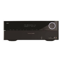
Harman Kardon AVR 170/230C Owner’s Manual (47 pages)
Owners Manual
Brand: Harman Kardon
|
Category: Receiver
|
Size: 5.49 MB
Table of Contents
-
Important Safety Information
3
-
System Remote Control Functions
8
-
Introduction to Home Theater
10
-
Typical Home Theater System
10
-
-
-
Placing the Left, Center and Right Speakers
10
-
Placing the Surround Speakers
10
-
-
Types of Home Theater System Connections
11
-
Source Device Connections
11
-
-
Connect Your Subwoofer
13
-
Connect Your Tv or Video Display
13
-
Connect Your Audio and Video Source Devices
13
-
Connect to Your Home Network
15
-
Connect the Radio Antennas
15
-
Connect the Trigger Output
15
-
Set up the Remote Control
16
-
Install the Batteries in the Remote Control
16
-
Program the Remote to Control Your Source Devices and Tv
16
-
-
-
Using the On-Screen Menu System
17
-
Configure the Avr for Your Speakers
17
-
Assign the Avr Input Connectors
18
-
Additional Source Setup Menu Items
19
-
-
Controlling the Volume
19
-
Listening through Headphones
19
-
Video Troubleshooting Tips
19
-
Listening to Fm and am Radio
20
-
Listening to Internet Radio (Vtuner)
20
-
Listening to an Ipod/Iphone/Ipad Device
20
-
Listening to Media on a Usb Device
20
-
Listening to Media VIA Your Home Network
21
-
Listening to Media VIA Airplay
22
-
Selecting a Surround Mode
22
-
-
-
Audio Processing and Surround Sound
23
-
Remote Channel-Control Punch-Through
26
-
Advanced Remote Control Programming
26
-
Programming Macro Commands
27
-
Advertisement
Related Products
-
Harman Kardon AVR 1700
-
Harman Kardon AVR 170
-
Harman Kardon AVR 1710S
-
Harman Kardon AVR 171S
-
Harman Kardon AVR 171 OS
-
Harman Kardon AVR 1710
-
Harman Kardon AVR 171/230C
-
Harman Kardon AVR 171
-
Harman Kardon AVR 141/230
-
Harman Kardon AVR 1566
Harman Kardon Categories
Receiver
Amplifier
Stereo Receiver
Speakers

CD Player
More Harman Kardon Manuals
Посмотреть инструкция для Harman Kardon AVR 170 бесплатно. Руководство относится к категории приемники, 1 человек(а) дали ему среднюю оценку 9.2. Руководство доступно на следующих языках: английский. У вас есть вопрос о Harman Kardon AVR 170 или вам нужна помощь? Задайте свой вопрос здесь
Не можете найти ответ на свой вопрос в руководстве? Вы можете найти ответ на свой вопрос ниже, в разделе часто задаваемых вопросов о Harman Kardon AVR 170.
Когда звук считается слишком громким?
Могут ли устройства разных марок подключаться друг к другу при помощи Bluetooth?
Как лучше всего выполнять чистку приемник?
Какой вес Harman Kardon AVR 170?
Какая высота Harman Kardon AVR 170?
Какая ширина Harman Kardon AVR 170?
Какая толщина Harman Kardon AVR 170?
Инструкция Harman Kardon AVR 170 доступно в русский?
Не нашли свой вопрос? Задайте свой вопрос здесь
В представленном списке руководства для конкретной модели Усилителя — Harman/Kardon AVR 170. Вы можете скачать инструкции к себе на компьютер или просмотреть онлайн на страницах сайта бесплатно или распечатать.
- Инструкции и файлы
- Характеристики
- Основные поломки
- Сервисы по ремонту
В случае если инструкция на русском не полная или нужна дополнительная информация по этому устройству, если вам нужны
дополнительные файлы: драйвера, дополнительное руководство пользователя (производители зачастую для каждого
продукта делают несколько различных документов технической помощи и руководств), свежая версия прошивки, то
вы можете задать вопрос администраторам или всем пользователям сайта, все постараются оперативно отреагировать
на ваш запрос и как можно быстрее помочь. Ваше устройство имеет характеристики:Тип: AV-ресивер, 5.1, Количество каналов: 5, Схемотехника: полупроводниковый, Мощность фронтальных каналов: 100 Вт (6 Ом, 1 кГц, 1% КГИ), Мощность фронтальных каналов (многоканальный режим): 100 Вт, Мощность центрального канала: 100 Вт, полные характеристики смотрите в следующей вкладке.
Для многих товаров, для работы с Harman/Kardon AVR 170 могут понадобиться различные дополнительные файлы: драйвера, патчи, обновления, программы установки. Вы можете скачать онлайн эти файлы для конкретнй модели Harman/Kardon AVR 170 или добавить свои для бесплатного скачивания другим посетителями.
Если вы не нашли файлов и документов для этой модели то можете посмотреть интсрукции для похожих товаров и моделей, так как они зачастую отличаются небольшим изменениями и взаимодополняемы.
Обязательно напишите несколько слов о преобретенном вами товаре, чтобы каждый мог ознакомиться с вашим отзывом или вопросом. Проявляйте активность что как можно бльше людей смогли узнать мнение настоящих людей которые уже пользовались Harman/Kardon AVR 170.

Александр
2017-11-28 19:23:27
не могу разобраться, почему перестал показывать домашний кинотеатр,проектор SONI
Основные и самые важные характеристики модели собраны из надежных источников и по характеристикам можно найти похожие модели.
| Общие характеристики | ||
| Тип | AV-ресивер, 5.1 | |
| Количество каналов | 5 | |
| Схемотехника | полупроводниковый | |
| Параметры усилителя | ||
| Мощность фронтальных каналов | 100 Вт (6 Ом, 1 кГц, 1% КГИ) | |
| Мощность фронтальных каналов (многоканальный режим) | 100 Вт | |
| Мощность центрального канала | 100 Вт | |
| Мощность тыловых каналов | 100 Вт | |
| Воспроизводимый диапазон частот | 10 — 100000 Гц | |
| Отношение сигнал/шум | 100 дБ | в режиме FM моно: 70 дБ, в режиме FM стерео: 68 дБ |
| Линейный вход/выход | ||
| Чувствительность | 250 мВ | |
| Входное сопротивление | 27 кОм | |
| Цифровая обработка звука | ||
| DSP | есть | |
| Интерфейсы | ||
| Входы | композитный x2, HDMI x6, коаксиальный x1, оптический x2, линейный x2 | |
| Выходы | сабвуфер x1, композитный x1, HDMI x1, наушники x1, линейный x1 | |
| Интерфейсы | RS-232, Ethernet RJ-45, внешний ИК-датчик | |
| Разъемы на передней панели | наушники, линейный вход, USB Type A | |
| Разъем для подключения наушников | 6.3 мм | |
| Разъемы для акустики | винтовые | |
| Функции | ||
| Экранное меню | есть | |
| Сетевые возможности | AirPlay, DLNA | |
| Декодеры | ||
| Dolby Digital | есть | |
| Dolby Digital Plus | есть | |
| Dolby TrueHD | есть | |
| Dolby Pro Logic | есть | |
| Dolby Pro Logic II | есть | |
| DTS | есть | |
| DTS-HD High Resolution Audio | есть | |
| DTS-HD Master Audio | есть | |
| Тюнер | ||
| Тип тюнера | цифровой | |
| Режимы | AM/FM | |
| Диапазон частот FM | 87.5 — 108.0 МГц | |
| Отношение сигнал/шум | 100 дБ | в режиме FM моно: 70 дБ, в режиме FM стерео: 68 дБ |
| Коэффициент гармоник | в режиме FM моно: 0.20 %, в режиме FM стерео: 0.30 % | |
| Функции | автоматическая настройка, ручная настройка, RDS | |
| Питание | ||
| Блок питания | встроенный | |
| Потребляемая мощность | 240 Вт | |
| Конструкция | ||
| Дисплей | есть | |
| Цветовое оформление | черный | |
| Размеры (ШхВхГ) | 440x165x377 мм | |
| Вес | 5.8 кг | |
| Дополнительная информация | ||
| Пульт ДУ | есть, управление другими компонентами |
Здесь представлен список самых частых и распространенных поломок и неисправностей у Усилителей. Если у вас такая поломка то вам повезло, это типовая неисправность для Harman/Kardon AVR 170 и вы можете задать вопрос о том как ее устранить и вам быстро ответят или же прочитайте в вопросах и ответах ниже.
| Название поломки | Описание поломки | Действие |
|---|---|---|
| Перегорают Защитные Предохранители | ||
| Автоусилитель Уходит В Защиту | ||
| При Включении Усилителя Загорается Красный Светодиод | ||
| Усилитель Включается, Но Звука Нет | ||
| Str-De698 | При Включении На Дисплее Protect | |
| После Сбоя При Обновлении Не Работает Кнопка Menu | Во Время Обновления Произошел Сбой В Эл/Сети И Процесс Обновления Был Нарушен. После Включения Ресивера Перестала Работать Кнопка Меню. Причем Сделать Сброс Удалось, Зажав И Удерживая Одновременно Кнопки Power И Menu. Но Это Не Помогло. Всё Остальное — Зв | |
| Не Работает Вход По Usb. | Усилитель Работает Нормально. При Подключении В Качестве Цап Компьютер Не Реагирует На Подключение Юсб Устройства, С Телефона Нет Вывода Сигнала. Другой Цап С Телефоном Работает Без Проблем. Е18 Был Куплен На Тайване, Под Воздействием Пары Пива В Надежде | |
| Туго Вращается Регулятор Громкости На Yamaha Rx-V459 | Очень Туго Вращается Регулятор Громкости На Yamaha Rx-V459. Пластиковая Ручка Просто Прокручивается … Невольно Хочется Смазать Как Ось Вращения | |
| Тюнер Работает. Все Остальные Входы:hdmi, Опто, Видео Не Работают | ||
| Нет Выхода Hdmi | На Hdmi Выходе Нет Сигнала. Иногда Проскакивает Изображение На Зеленом Фоне. Сильно Греется Микросхема Is 3850 (Adv 7322). Не Могу Найти Прошивку. | |
| Не Работают Каналы Мощности На Фронтальные Колонки | При Включении Усилителя Не Работают Фронтальные Колонки, При Запуске Теста Выдает Code 33 | |
| Vsx 520 K | Не Включается. Ничего Не Сгорели Не Щелкнет | |
| При Ресивер | ||
| Хлопок В Колонках После Включения Усилителя Musical Fidelity M6Si | После Включения Усилителя Musical Fidelity M6Si Примерно Через Минуту Слышен Сильный Хлопок В Колонках . После Этого Усилительработае Хорошо . Это Происходит Не Каждый День . Один Раз В Три Дня . Но Это Не Всегда . Иногда При Каждом Включении В Тот Же Ден |
В нашей базе сейчас зарегестрированно 18 353 сервиса в 513 города России, Беларусии, Казахстана и Украины.

МТЕХНИК
⭐
⭐
⭐
⭐
⭐
Адресс:
Острякова ул., д. 6
Телефон:
74991572252
Сайт:
n/a
Время работы
Время работы не указано
РАДИО СЕРВИС
⭐
⭐
⭐
⭐
⭐
Адресс:
ул. Новослободская, д. 48
Телефон:
79268522278
Сайт:
n/a
Время работы
Будни: с 1000 до 1800
Суббота: выходной
Воскресенье: выходной
СЕРВИСНЫЙ ЦЕНТР
⭐
⭐
⭐
⭐
⭐
Адресс:
Генерала Кузнецова, 28 к1
Телефон:
74957048101
Сайт:
n/a
Время работы
Будни: с 1000 до 2200
Суббота: с 1000 до 2200
Воскресенье: с 1000 до 2000
БРИКС
⭐
⭐
⭐
⭐
⭐
Адресс:
Новощукинская, 1
Телефон:
74991930137
Сайт:
n/a
Время работы
Время работы не указано
ГЛАВКОМП
⭐
⭐
⭐
⭐
⭐
Адресс:
22-ой км. Киевского шоссе
Телефон:
74952369676
Сайт:
n/a
Время работы
Ежедневно: с 0930 до 2200
HARMAN KARDON AVR-170 5.1 A/V Receiver (Unboxing+kleines Review)
16:37
Очень доволен
хочу
авпваы
Хочу купить
ирлдоьвап ькеьпрлджыкеь дзьакерджь щзрбкежбрь апкыезрбкыеджрбеджр щзапбкерл
Только приобрела,а инструкции нет
Только приобрела,а инструкции нет
Отвалился распрыскиватель
Хорошее руководство по эксплуатации
Законодательство обязывает продавца передать покупателю, вместе с товаром, руководство по эксплуатации Harman Kardon AVR 170. Отсутствие инструкции либо неправильная информация, переданная потребителю, составляют основание для рекламации в связи с несоответствием устройства с договором. В законодательстве допускается предоставлении руководства в другой, чем бумажная форме, что, в последнее время, часто используется, предоставляя графическую или электронную форму инструкции Harman Kardon AVR 170 или обучающее видео для пользователей. Условием остается четкая и понятная форма.
Что такое руководство?
Слово происходит от латинского «instructio», тоесть привести в порядок. Следовательно в инструкции Harman Kardon AVR 170 можно найти описание этапов поведения. Цель инструкции заключается в облегчении запуска, использования оборудования либо выполнения определенной деятельности. Инструкция является набором информации о предмете/услуге, подсказкой.
К сожалению немного пользователей находит время для чтения инструкций Harman Kardon AVR 170, и хорошая инструкция позволяет не только узнать ряд дополнительных функций приобретенного устройства, но и позволяет избежать возникновения большинства поломок.
Из чего должно состоять идеальное руководство по эксплуатации?
Прежде всего в инструкции Harman Kardon AVR 170 должна находится:
— информация относительно технических данных устройства Harman Kardon AVR 170
— название производителя и год производства оборудования Harman Kardon AVR 170
— правила обслуживания, настройки и ухода за оборудованием Harman Kardon AVR 170
— знаки безопасности и сертификаты, подтверждающие соответствие стандартам
Почему мы не читаем инструкций?
Как правило из-за нехватки времени и уверенности в отдельных функциональностях приобретенных устройств. К сожалению само подсоединение и запуск Harman Kardon AVR 170 это слишком мало. Инструкция заключает ряд отдельных указаний, касающихся функциональности, принципов безопасности, способов ухода (даже то, какие средства стоит использовать), возможных поломок Harman Kardon AVR 170 и способов решения проблем, возникающих во время использования. И наконец то, в инструкции можно найти адресные данные сайта Harman Kardon, в случае отсутствия эффективности предлагаемых решений. Сейчас очень большой популярностью пользуются инструкции в форме интересных анимаций или видео материалов, которое лучше, чем брошюра воспринимаются пользователем. Такой вид инструкции позволяет пользователю просмотреть весь фильм, не пропуская спецификацию и сложные технические описания Harman Kardon AVR 170, как это часто бывает в случае бумажной версии.
Почему стоит читать инструкции?
Прежде всего здесь мы найдем ответы касательно конструкции, возможностей устройства Harman Kardon AVR 170, использования отдельных аксессуаров и ряд информации, позволяющей вполне использовать все функции и упрощения.
После удачной покупки оборудования/устройства стоит посвятить несколько минут для ознакомления с каждой частью инструкции Harman Kardon AVR 170. Сейчас их старательно готовят или переводят, чтобы они были не только понятными для пользователя, но и чтобы выполняли свою основную информационно-поддерживающую функцию.
Покупал агрегат исключительно из-за внешнего вида и цены. Мне понравился минималистичный дизайн, который очень подходил к LP-проигрывателю Music Hall, в паре с которым и предполагалась его работа. Но, пожалуй, заменю его на что то более приятное в использовании, а не только красивое, а этот, скорее всего, пущу на озвучку комнат и для интернет-радио, штука удобная.
Провода кидать не хотелось, поэтому я его подключил к МГТС-овскому GPON модему через Wi-Fi, настроив роутер, как Wi-Fi повторитель. Повозившись изрядно.
Если кому станет интересно как, ищите «Роутер, как репитер»
Достоинства: 1. Стильный внешний вид. Этого не отнять, хоть и впечатление сгладилось неприятными тактильными ощущениями в работе.
2. Просторный корпус.
3. Лёгкий (в нём используется импульсный блок питания).
4. Цена.
Недостатки: 1. Встроенный в аппарат Wi-Fi модуль ограничен применением только с продукцией Apple в качестве Air-play.
2. На пульте куча кнопок (65! и по больше части довольно мелких), но при этом с пульта недоступны некоторые нужные функции, например настройки работы декодера (stereo/dolby и т.д.), нужно жать кнопки на корпусе. Хотя это можно сделать один раз для каждого источника и забыть или пользоваться редко.
3. Эти самые кнопки на корпусе подписаны очень мелким шрифтом, который, вопреки моим ожиданиям, не подсвечивается во включенном состоянии, из-за чего они плохо читаемы. Сами кнопки не очень приятны на ощупь, а тактильные ощущения от нажатия, как от дешёвой китайской игрушки.
4. Регулятор громкости утоплен почти заподлицо и не выдвигается при включении, на что я тоже рассчитывал. Непривычно и
Никита Г.8 лет назад
яндекс маркет
До этого я являлся счастливым владельцем «Pioneer VSX422». Счастливым был до тех пор, пока он не сломался, а за ремонт заломили 2 стоимости ресивера. Пока он был рабочий, настраивал я его по всякому, и с помощью MCACC калибровки, и вручную, и режимы разные пробовал, но звук особо улучшить не удавалось. Грешил на акустику «Sony SS-FCR6000», но после покупки Harman/Kardon я понял что акустика нормальная. Даже тыловые колонки не такое днище как я думал, они буквально ожили с новым ресивером. Возможно я неправильно настроил пионер.
Также использовал автоматическую калибровку, в настройках ресивера особо не лазил, да и настроек там мало. Звук из коробки очень хороший, что важно для тех кто не умеет толково настраивать подобную технику.
Достоинства: Чистый звук
Минимум настроек, для нубов типа меня
Офигительный минималистичный дизайн и подсветка крутилки просто великолепны!
Легкий. Возможно с точки зрения технической начинки это и минус, но я в ней не шарю, поэтому для меня плюс
Недостатки: Возможно кому-то не понравится то, что ресивер уходит в сон ночью, когда на него не идут сигналы. Насколько я знаю это поведение настраивается.
Для меня лично это плюс т.к. предыдущий ресивер вместо ухода в сон посреди ночи начинал противно шипеть тыловыми колонками у изголовья кровати, что дико бесило и приходилось ставить mute вручную.
роман п.8 лет назад
яндекс маркет
Не хотел покупать обычный усилитель, потому что это уже не современно. Опробовал все фишки данного аппарата и очень доволен (DLNA, Windows media player, USB (только fat32), AirPlay, HK Remote, Интернет радио (очень большой выбор на различные тематики разных стран). Подключил через него домашнюю TV приставку билайна. Пробовал по сетке запускать mp3 320 и flac (хотя в официальной доке он не значился), воспроизводит нормально. Прикольно лежа на диване рулить с iphone или Андроида аудио файлами, которые расположены на DLNA сервере (на компе). Звук чистый, но кажется средних не хватает для просмотра телевизора (возможно не до настроил). И еще кажется мощности не особо хватает для 100вт колонок Jamo (2шт.). При подключении 5.1 вообще очень тихо будет. До того как отключил лишние каналы и не включил virtual surround (увеличивает громкость) выкручивал громкость почти на всю.
Достоинства: Очень много функций и хороший звук.
Недостатки: Слабоват для моей акустики. И со средними пока не разобрался.
Игорь Алюшкевич8 лет назад
яндекс маркет
не советую обновлять по.
Достоинства: Чистейший звук, стильный дизайн, airplay, Hdmi — ARC возможность управлять пультом от телевизора (включение — выключение, громкость)
Недостатки: не обнаружено
Пользователь удален9 лет назад
яндекс маркет
просто посмотрите на его вес — менее 6 кило ! и больше вопроса купит его или нет не возникнет. это худшее что можно представить. удивлен что такая фирма такое творение вообще выпустило на рынок
Достоинства: симпатичный дизайн
Недостатки: это худшее творение от харман кардон. почти не читает музыку по ЮСБ, отвратительная эргономика, уход в спящий режим.
Андрей М.9 лет назад
яндекс маркет
Оставлял здесь коммент о Yamaha rx-v 473 писал о ней положительно, но наверное был не в себе.Потому как спустя полгода стало невозможным слушать это инженерное чудо японских мастеров. поэтому буду писать исходя из опыта обладателя 2-х моделей.Harman- божественнен.Наконец-то я услышал высокие.Как yamahe удалось почти полностью убрать высокие, я не знаю.я думал у меня пищалки сгорели.Детализация хармана прекрасная.четкая передача тылов,центров,фронтов в кино.В музыке-в режиме стерео раскладывает сигнал как и задумывал музыкант.картина на слух может раскладываться на несколько слоёв(внизу шуршат тарелки,в середине гитара и в целом звуковом пространстве- мелодия и по комнате перестукиваются бонго-божественно)саб- не особо нужен,бассы приличные, но для кино вещь необходимая, так как придаёт более ощутимый эффект.Читает USB флешки,хард 250(только в fat32).СД пускал по аналогу и HDMI.В принципе разница не очень сильная.Аналог имеет чуть лучшую мягкость,стерео эффект,цифра более сбалансированный звук.не очень понравился пульт и навигация.здесь ямаха вне конкуренции.с другой стороны с ямахой сидишь и пытаешся вымучить звук, а харман просто играет и играет прекрасно.кстати хармановский пульт можно программировать,но инструкции на русском нет,а мне это представляется не очень лёгким делом.очень понравился режим Logic7 Music.Звук добавляется в тылы, но не сильно, в результате получается приятный окружающий звук.В общем, по сравнению с Ямахой, открываю для себя новое звучание старых сд.МП3 также хороши,но всё-таки сд мощнее.Кино в DolbyDigital- идеально.Достаточный сигнал как в тылах, так и в центре,фронтах.Дизайн-по мне один из лучших.В общем, я действительно очень доволен и этот ресивер я ещё очень не скоро захочу обновить.устраивает на все 100, тем более, что в Москве появился по цене в 13900р..в будущем хочу обновить акустику от harman corp.
p.s прошло 2 месяца-божественен.давно такого не встречал.внутри душевный спокой.НЕ ХОЧУ менять.
Достоинства: Потрясающее качество звука, отменная детализация и прорисовка звуковой картины
Недостатки: не очень удобный пульт
Валерий Т.9 лет назад
яндекс маркет
Все хорошо в этом ресивере, НО, если бы не глюк который меня уже достал, я бы не выражался столь отрицательно о нем. В режиме AUX апарат через 20-30 минут уходит в sleep и я не могу это победить ничем. Перепрошивал, перенастрйвал, но ничего не помогло.
Достоинства: Хороший звук
Недостатки: Неудобная эргономика, неудобный пульт, сам уходит в спящий режим
Алексей К.10 лет назад
яндекс маркет
Работает в купе с акустикой Варфадейл даймонд 9.5 — 2 фронтальных колонки. Сабик и не нужен. Звук наилудший. Выбирал более месяца между пионером 822 и ямахой 471.
Достоинства: Звук, ЮСБ и мн. другое. Все кроме работы по сети. Подключен к маршрутизатору АЗУС N66U. По сетке видит жесткий диск, подключенный к маршрутизатору, песни читает с горем пополам, можно сказать не читает. Виснет по полной.
Недостатки: Сеть тупит, интернет радио вообще не работает, потоковое аудио воспроизводит с горем пополам