
Скачать
S-7000DD
INSTRUCTION MANUAL
Please read this manual before using the machine.
Please keep this manual within easy reach for quick reference.
SINGLE NEEDLE STRAIGHT LOCK STITCHER
WITH THREAD TRIMMER
Page 1 — S-7000DD
S-7000DD INSTRUCTION MANUAL Please read this manual before using the machine. Please keep this manual within easy reach for quick reference. SINGLE
Page 2
S-7000DD 1. MACHINE SPECIFICATIONS1 1. MACHINE SPECIFICATIONS 3 4 Quick reverse ○ ○ Thread wiper ○ 3 3A 5 0540DUse For light to medium-
Page 3 — CAUTION
S-7000DD 2. INSTALLATION22. INSTALLATION CAUTION Machine installation should only be carried out by a qualified technician. Contact your
Page 4 — WARNING
S-7000DD 2. INSTALLATION3 2-1. Table processing diagram ・ The top of the table should be 40 mm in thickness and should be strong enough to hold the
Page 5
S-7000DD 2. INSTALLATION43. Rubber cushions (1) Rubber cushions [2 pcs] ) Rubber cushions [2 pcs] (2) Nails [4 pcs] (2) Nails [4 pcs] (3) Head
Page 6 — [3] Warning labels
S-7000DD 2. INSTALLATION5 5. Knee lifter plate <Knee lifter adjustment> 1. Turn the machine pulley so that the feed dog is below the top of t
Page 7 — (100 V/400 V system only)
S-7000DD 2. INSTALLATION62-3. Lubrication CAUTION Do not connect the power cord until lubrication has been completed, otherwise the machine may ope
Page 8 — CONTENTS
S-7000DD 2. INSTALLATION7 2-4. Connecting the cords CAUTION Contact your Brother dealer or a qualified electrician for any electrical work tha
Page 9
S-7000DD 2. INSTALLATION82-4-2. Other cords For Europe specifications, Americas 220V specifications and 100 V/400 V system specifications, connect t
Page 10 — 1. MACHINE SPECIFICATIONS
S-7000DD 2. INSTALLATION9 3. Install the cores (10) in the two places shown in the illustration. 0588D (10) Core [2 pcs] (11) Screws [2 pcs] (12) Wa
Page 11 — 2. INSTALLATION
S-7000DD 2. INSTALLATION10<For Americas 220V specifications> (1) Power switch (2) Screws [2 pcs] (3) 3-pin power supply connector (
Page 12 — 2-2. Installation
S-7000DD Thank you very much for buying a BROTHER sewing machine. Before using your new machine, please read the safety instructions and the explana
Page 13 — 3. Rubber cushions
S-7000DD 2. INSTALLATION11 <For 100V/400V system specifications> (1) Power switch (2) Screws [2 pcs] Operator 4145M(3) Transformer
Page 14 — 5. Knee lifter plate
S-7000DD 3. USING THE OPERATION PANEL (BASIC OPERATIONS) 123. USING THE OPERATION PANEL (BASIC OPERATIONS) 3-1. Names and functions ・ The operation
Page 15 — CAUTION
S-7000DD 3. USING THE OPERATION PANEL (BASIC OPERATIONS) 13 Power indicator 0489D (7) Thread trimming disable/F1 key When this ke
Page 16 — CAUTION
S-7000DD 3. USING THE OPERATION PANEL (BASIC OPERATIONS) 143-2. Sewing start and end backtack stitches 0841M 1 Setting start backtack stitc
Page 17 — 2-4-2. Other cords
S-7000DD 3. USING THE OPERATION PANEL (BASIC OPERATIONS) 15 3-3. Sewing continuous backtack stitches 3655M 1 Setting continuous backtack st
Page 18
S-7000DD 4. USING THE OPERATION PANEL (ADVANCED OPERATIONS) 164. USING THE OPERATION PANEL (ADVANCED OPERATIONS) The operations described in this se
Page 19
S-7000DD 4. USING THE OPERATION PANEL (ADVANCED OPERATIONS) 17 4-2-2. Setting the start backtack sewing speed 1 Press the SEL key so that the SPEED
Page 20
S-7000DD 4. USING THE OPERATION PANEL (ADVANCED OPERATIONS) 184-3. Setting the counters The lower thread counter, thread trimming counter and needle
Page 21 — (BASIC OPERATIONS)
S-7000DD 4. USING THE OPERATION PANEL (ADVANCED OPERATIONS) 19 4-3-2. Thread trimming counter The lower thread counter can be used to let you know a
Page 22 — Power indicator
S-7000DD 4. USING THE OPERATION PANEL (ADVANCED OPERATIONS) 204-3-3. Needle replacement counter <Setting the needle replacement counter initial v
Page 23 — Example:
SAFETY INSTRUCTIONS [1] Safety indications and their meanings This instruction manual and the indications and symbols that are used on the machine
Page 24
S-7000DD 4. USING THE OPERATION PANEL (ADVANCED OPERATIONS) 21 4-4. Setting basic functions If you turn on the power switch while pressing the threa
Page 25 — (ADVANCED OPERATIONS)
S-7000DD 4. USING THE OPERATION PANEL (ADVANCED OPERATIONS) 224-4-2. Correction sewing When correction sewing is enabled, sewing will be carried out
Page 26
S-7000DD 4. USING THE OPERATION PANEL (ADVANCED OPERATIONS) 23 4-4-3. Setting thread wiping The initial setting value is ON. If the thread wiper is
Page 28
S-7000DD 4. USING THE OPERATION PANEL (ADVANCED OPERATIONS) 25 4-6. Resetting all settings to their defaults If the sewing machine stops operating n
Page 29
S-7000DD 5. CLEANING265. CLEANING CAUTION Turn off the power switch before carrying out cleaning. The machine may operate if the tre
Page 31 — 4-4-2. Correction sewing
S-7000DD 7. STANDARD ADJUSTMENTS287. STANDARD ADJUSTMENTS CAUTION Maintenance and inspection of the sewing machine should only be carried
Page 33
S-7000DD 7. STANDARD ADJUSTMENTS307-3. Adjusting of the feed dog height The standard height of the feed dog (1) when it is raised as far as possible
Page 34
[2] Notes on safety DANGER Wait at least 5 minutes after turning off the power switch and disconnecting the power cord from the wall outlet before o
Page 35 — 5. CLEANING
S-7000DD 7. STANDARD ADJUSTMENTS31 7-5. Adjusting the needle bar height Reference line (a), which is the second line from the bottom of the needle b
Page 36
S-7000DD 7. STANDARD ADJUSTMENTS327-7. Adjusting the needle and rotary hook timing The tip of the rotary hook (3) should be aligned with the center
Page 37 — 7. STANDARD ADJUSTMENTS
S-700033 DD 7. STANDARD ADJUSTMENTS7-8. Adjusting the rotary hook lubrication amount CAUTION Be careful not to touch your fingers or the lubricatio
Page 38
S-7000DD 8. TROUBLESHOOTING 348. TROUBLESHOOTING ・ Please check the following points before calling for repairs or service. ・ If the following remed
Page 39
S-7000DD 8. TROUBLESHOOTING 35 Problem Possible cause Page 5 Skipped stitches at sewing start Thread unravelling at sewing start ・ Is the thread t
Page 40
S-7000DD 8. TROUBLESHOOTING 36 Problem Possible cause Page 8 Material slippage ・ Is the presser foot pressure too strong? Adjust the presser foot pr
Page 41
S-7000DD 8. TROUBLESHOOTING 37 Problem Possible cause Page 13 Broken needles ・ Is the material being pushed or pulled with excessive force during s
Page 42
S-7000DD 8. TROUBLESHOOTING 388-2. Error code displays If an error code appears on the operation panel display 1. Make a note of the error code and
Page 43 — 8. TROUBLESHOOTING
S-7000DD 8. TROUBLESHOOTING 39 Error code Possible cause Page E090 Treadle connector is not connected. ・ Is the 3-pin treadle connector inside th
Page 44
S-7000DD 8. TROUBLESHOOTING 40 Error code Possible cause Page E150 Motor is overheating. ・ This is displayed when the motor becomes abnormally hot
Page 45
CAUTION Sewing This sewing machine should only be used by operators who have received the necessary training in safe use beforehand. The s
Page 46
S-7000DD 8. TROUBLESHOOTING 41 Error code Possible cause Page E701 Abnormally high power supply voltage. ・ Does the power supply voltage match th
Page 48
INSTRUCTION MANUAL * Please note that the contents of this manual may differ slightly from the actual product pur
Page 49
[3] Warning labels The following warning labels appear on the sewing machine. Please follow the instructions on the labels at all times when using th
Page 50
Control box Oil tank Transformer box (100 V/400 V system only)0591DS-7000DD v
![]()
|
S-7000DD |
INSTRUCTION MANUAL |
Please read this manual before using the machine.
Please keep this manual within easy reach for quick reference.
SINGLE NEEDLE STRAIGHT LOCK STITCHER
WITH THREAD TRIMMER
Thank you very much for buying a BROTHER sewing machine. Before using your new machine, please read the safety instructions and the explanations given in the instruction manual.
With industrial sewing machines, it is normal to carry out work while positioned directly in front of moving parts such as the needle and thread take-up, and consequently there is always a danger of injury that can be caused by these parts. Follow the instructions from training personnel and instructors regarding safe and correct operation before operating the machine so that you will know how to use it correctly.
S-7000DD
SAFETY INSTRUCTIONS
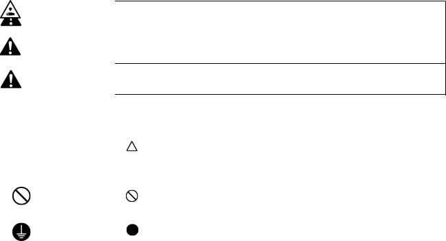
[1] Safety indications and their meanings
This instruction manual and the indications and symbols that are used on the machine itself are provided in order to ensure safe operation of this machine and to prevent accidents and injury to yourself or other people.
The meanings of these indications and symbols are given below.
Indications
|
DANGER |
The instructions which follow this term indicate situations where failure to follow the |
|
instructions will result in death or serious injury. |
|
|
WARNING instructions could result in death or serious injury. |
|
|
The instructions which follow this term indicate situations where failure to follow the |
|
|
instructions may result in minor or moderate injury. |
|
|
CAUTION |
|
|
The instructions which follow this term indicate situations where failure to follow the |
|
Symbols
|
· · · · · |
This symbol ( |
) indicates something that you should be careful of. The picture inside the triangle |
|
indicates the nature of the caution that must be taken. |
||
|
(For example, the symbol at left means “beware of injury”.) |
||
|
· · · · · |
This symbol ( |
) indicates something that you must not do. |
|
· · · · · |
This symbol ( |
) indicates something that you must do. The picture inside the circle indicates the |
|
nature of the thing that must be done. |
(For example, the symbol at left means “you must make the ground connection”.)
[2] Notes on safety
 DANGER
Wait at least 5 minutes after turning off the power switch and disconnecting the power cord from the wall outlet before opening the cover of the control box. Touching areas where high voltages are present can result in severe injury.
 WARNING
Do not allow any liquids to get onto this sewing machine, otherwise fire, electric shocks or operating problems may occur.
If any liquid gets inside the sewing machine (machine head or control box), immediately turn off the power and disconnect the power plug from the electrical outlet, and then contact the place of purchase or a qualified technician.
 CAUTION
Environmental requirements
Use the sewing machine in an area which is free from sources of strong electrical noise such as electrical line noise or static electric noise.
Sources of strong electrical noise may cause problems with correct operation.
Any fluctuations in the power supply voltage should be within 10% of the rated voltage for the machine.
Voltage fluctuations which are greater than this may cause problems with correct operation.
The power supply capacity should be greater than the requirements for the sewing machine’s power consumption.
Insufficient power supply capacity may cause problems with correct operation.
The ambient temperature should be within the range of 5 C to 35 C during use.
Temperatures which are lower or higher than this may cause problems with correct operation.
The relative humidity should be within the range of 45% to 85% during use, and no dew formation should occur in any devices.
Excessively dry or humid environments and dew formation may cause problems with correct operation.
In the event of an electrical storm, turn off the power and disconnect the power cord from the wall outlet. Lightning may cause problems with correct operation.
Installation
Machine installation should only be carried out by a qualified technician.
Contact your Brother dealer or a qualified electrician for any electrical work that may need to be done.
The sewing machine weighs approximately 32 kg (70lb). The installation should be carried out by two or more people.
Do not connect the power cord until installation is complete. The machine may operate if the treadle is depressed by mistake, which could result in injury.
Turn off the power switch before inserting or removing the plug, otherwise damage to the control box could result.
Be sure to connect the ground. If the ground connection is not secure, you run a high risk of receiving a serious electric shock, and problems with correct operation may also occur.
When securing the cords, do not bend the cords excessively or fasten them too hard with staples, otherwise there is the danger that fire or electric shocks could occur.
If using a work table which has casters, the casters should be secured in such a way so that they cannot move.
Secure the table so that it will not move when tilting back the machine head. If the table moves, it may crush your feet or cause other injuries.
Use both hands to hold the machine head when tilting it back or returning it to its original position. If only one hand is used, the weight of the machine head may cause your hand to slip, and your hand may get caught.
Be sure to wear protective goggles and gloves when handling the lubricating oil and grease, so that they do not get into your eyes or onto your skin, otherwise inflammation can result.
Furthermore, do not drink the oil or eat the grease under any circumstances, as they can cause vomiting and diarrhea.
Keep the oil out of the reach of children.
 CAUTION
Sewing
This sewing machine should only be used by operators who have received the necessary training in safe use beforehand.
The sewing machine should not be used for any applications other than sewing.
Be sure to wear protective goggles when using the machine.
If goggles are not worn, there is the danger that if a needle breaks, parts of the broken needle may enter your eyes and injury may result.
Turn off the power switch at the following times. The machine may operate if the treadle is depressed by mistake, which could result in injury.
When threading the needle
When replacing the bobbin and needle
When not using the machine and when leaving the machine unattended
If using a work table which has casters, the casters should be secured in such a way so that they cannot move.
Attach all safety devices before using the sewing machine. If the machine is used without these devices attached, injury may result.
Do not touch any of the moving parts or press any objects against the machine while sewing, as this may result in personal injury or damage to the machine.
Secure the table so that it will not move when tilting back the machine head. If the table moves, it may crush your feet or cause other injuries.
Use both hands to hold the machine head when tilting it back or returning it to its original position. If only one hand is used, the weight of the machine head may cause your hand to slip, and your hand may get caught.
If an error occurs in machine operation, or if abnormal noises or smells are noticed, immediately turn off the power switch. Then contact your nearest Brother dealer or a qualified technician.
If the machine develops a problem, contact your nearest Brother dealer or a qualified technician.
Cleaning
Turn off the power switch before carrying out cleaning. The machine may operate if the treadle is depressed by mistake, which could result in injury.
Secure the table so that it will not move when tilting back the machine head. If the table moves, it may crush your feet or cause other injuries.
Use both hands to hold the machine head when tilting it back or returning it to its original position. If only one hand is used, the weight of the machine head may cause your hand to slip, and your hand may get caught.
Be sure to wear protective goggles and gloves when handling the lubricating oil and grease, so that they do not get into your eyes or onto your skin, otherwise inflammation can result.
Furthermore, do not drink the oil or eat the grease under any circumstances, as they can cause vomiting and diarrhea.
Keep the oil out of the reach of children.
Maintenance and inspection
Maintenance and inspection of the sewing machine should only be carried out by a qualified technician.
Ask your Brother dealer or a qualified electrician to carry out any maintenance and inspection of the electrical system.
Turn off the power switch and disconnect the power cord from the wall outlet at the following times, otherwise the machine may operate if the treadle is depressed by mistake, which could result in injury.
When carrying out inspection, adjustment and maintenance
When replacing consumable parts such as the rotary hook and knife
Always be sure to turn off the power switch and then wait one minute before opening the motor cover. If you touch the surface of the motor, it may cause burns.
If the power switch needs to be left on when carrying out some adjustment, be extremely careful to observe all safety precautions.
Secure the table so that it will not move when tilting back the machine head. If the table moves, it may crush your feet or cause other injuries.
Use both hands to hold the machine head when tilting it back or returning it to its original position.
If only one hand is used, the weight of the machine head may cause your hand to slip, and your hand may get caught.
When replacing parts and installing optional accessories, be sure to use only genuine Brother parts.
Brother will not be held responsible for any accidents or problems resulting from the use of non-genuine parts.
If any safety devices have been removed, be absolutely sure to re-install them to their original positions and check that they operate correctly before using the machine.
To prevent accidents and problems, do not modify the machine yourself.
Brother will not be held responsible for any accidents or problems resulting from modifications made to the machine.

[3] Warning labels
The following warning labels appear on the sewing machine.
Please follow the instructions on the labels at all times when using the machine. If the labels have been removed or are difficult to read, please contact your nearest Brother dealer.
1
|
2 |
Touching areas where high voltages are present can |
|
result in severe injury. Turn off the power before |
opening the cover.
3
|
* Safety devices: (A) Finger guard |
(C) Motor cover |
|
(B) Thread take-up cover |
|
4 |
Be careful not to get your hands |
||||
|
caught |
when |
returning the |
|||
|
machine head to its original |
|||||
|
5 |
position after it has been tilted. |
||||
|
Be careful to avoid injury from |
|||||
|
the moving thread take-up. |
|||||
|
6 |
High temperature warning |
||||
|
display |
|||||
|
7 |
Be sure to connect the ground. If |
||||
|
the ground connection is not |
|||||
|
secure, you run a high risk of |
|||||
|
receiving |
a |
serious electric |
|||
|
shock, and problems with correct |
|||||
|
operation may also occur. |
|
8 |
Direction of operation |
|
9
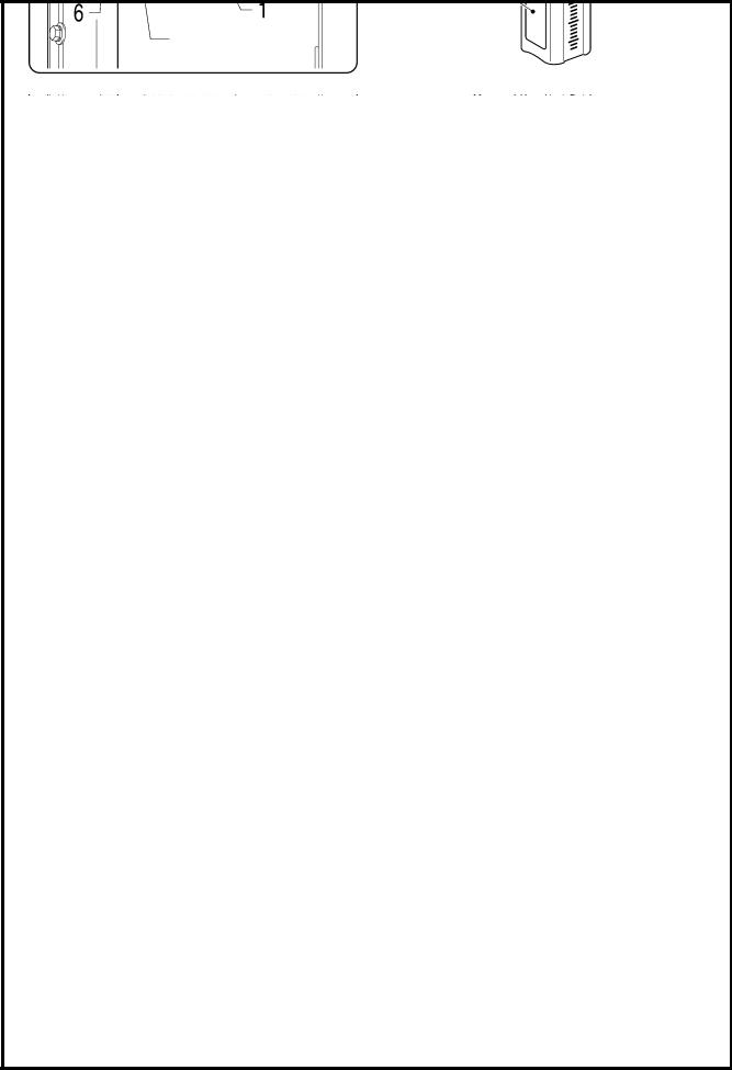
Transformer box
(100 V/400 V system only)
Control box
Oil tank
0591D

CONTENTS
|
1. MACHINE SPECIFICATIONS ……………… |
1 |
|
2. INSTALLATION …………………………………….. |
2 |
|
2-1. Table processing diagram……………………….. |
3 |
|
2-2. Installation ……………………………………………. |
3 |
|
2-3. Lubrication ……………………………………………. |
6 |
|
2-4. Connecting the cords………………………………. |
7 |
|
2-4-1. Connecting the cords ………………………….. |
7 |
|
2-4-2. Other cords…………………………………………. |
8 |
|
3. USING THE OPERATION PANEL |
|
|
(BASIC OPERATIONS)……………………….. |
12 |
|
3-1. Names and functions ……………………………… |
12 |
|
3-2. Sewing start and end backtack stitches …… |
14 |
|
3-3. Sewing continuous backtack stitches ………. |
15 |
|
4. USING THE OPERATION PANEL |
|
|
(ADVANCED OPERATIONS)……………… |
16 |
|
4-1. Switching the 4-column display ………………. |
16 |
|
4-2. Setting the sewing speed ………………………… |
16 |
|
4-2-1. Setting the maximum sewing speed …… |
16 |
|
4-2-2. Setting the start backtack |
|
|
sewing speed………………………………………. |
17 |
|
4-3. Setting the counters……………………………….. |
18 |
|
4-3-1. Lower thread counter…………………………. |
18 |
|
4-3-2. Thread trimming counter…………………… |
19 |
|
4-3-3. Needle replacement counter……………….. |
20 |
|
4-4. Setting basic functions……………………………. |
21 |
|
4-4-1. Changing the needle stop position………. |
21 |
|
4-4-2. Correction sewing ………………………………. |
22 |
|
4-4-3. Setting thread wiping…………………………. |
23 |
|
4-5. Adjusting the needle up stop position………. |
24 |
|
4-6. Resetting all settings to their defaults …….. |
25 |
|
5. CLEANING……………………………………………… |
26 |
|
6. REPLACING THE FIXED KNIFE |
|
|
AND MOVABLE KNIFE ………………………… |
27 |
|
7. STANDARD ADJUSTMENTS……………… |
28 |
|
7-1. Adjusting arm thread guide R…………………. |
28 |
|
7-2. Adjusting the presser foot height…………….. |
29 |
|
7-3. Adjusting of the feed dog height ……………… |
30 |
|
7-4. Adjusting the feed dog angle …………………… |
30 |
|
7-5. Adjusting the needle bar height………………. |
31 |
|
7-6. Adjusting the needle and feed |
|
|
mechanism timing …………………………………. |
31 |
|
7-7. Adjusting the needle and rotary hook |
|
|
timing……………………………………………………. |
32 |
|
7-8. Adjusting the rotary hook lubrication |
|
|
amount …………………………………………………. |
33 |
|
8. TROUBLESHOOTING………………………….. |
34 |
|
|
8-1. |
Sewing ………………………………………………….. |
34 |
|
8-2. |
Error code displays ………………………………… |
38 |
|
9. 7-SEGMENT DISPLAY…………………………. |
42 |
S-7000DD

S-7000DD
1. MACHINE SPECIFICATIONS
1. MACHINE SPECIFICATIONS
|
3 |
4 |
|
|
Quick reverse |
○ |
○ |
|
Thread wiper |
○ |
0540D
|
3 |
3A |
5 |
||||
|
Use |
For light to |
For medium-weight |
For heavy-weight |
|||
|
medium-weight materials |
materials |
materials |
||||
|
Max. sewing speed |
4,500 sti/min |
4,500 sti/min |
4,000 sti/min |
|||
|
Sewing speed at the time of shipment |
4,000 sti/min |
|||||
|
Start backtacking and continuous |
220 — 3,000 sti/min |
|||||
|
backtacking speed |
||||||
|
End backtacking speed |
1,800 sti/min |
|||||
|
Max. stitch length |
4.2 mm |
5 mm |
||||
|
Presser foot height |
Lifting lever |
6 mm |
||||
|
Knee lifter |
13 mm |
|||||
|
Feed dog height |
0.8 mm |
1.0 mm |
1.2 mm |
|||
|
Needle (DB x 1, DP x 5) |
#11 — #18 |
#19 — #22 |
||||
|
Motor |
AC servo motor (4-pole, 450 |
W) |
||||
|
Control circuit |
Microprocessor |
![]()
2. INSTALLATION
2. INSTALLATION
 CAUTION
Machine installation should only be carried out by a qualified technician.
Contact your Brother dealer or a qualified electrician for any electrical work that may need to be done.
The sewing machine weighs approximately 32 kg (70lb). The installation should be carried out by two or more people.
Do not connect the power cord until installation is complete. The machine may operate if the treadle is depressed by mistake, which could result in injury.
Secure the table so that it will not move when tilting back the machine head. If the table moves, it may crush your feet or cause other injuries.
Use both hands to hold the machine head when tilting it back or returning it to its original position. If only one hand is used, the weight of the machine head may cause your hand to slip, and your hand may get caught.
About the machine set-up location
Do not set up this sewing machine near other equipment such as televisions, radios or cordless telephones, otherwise such equipment may be affected by electronic interference from the sewing machine.
The sewing machine should be plugged directly into an AC wall outlet. Operation problems may result if extension cords are used.
0475D
Carrying the machine
The sewing machine should be carried by the arm and the motor cover by two people as shown in the illustration.
*Do not hold by any part other than the motor cover. If this is not observed, it may result in damage to the sewing machine.
0476D
Tilting back the machine head
Hold section (A) with your foot so that the table does not move, and then push the arm with both hands to tilt back the machine head.
2101B
Returning the machine head to the upright position
1.Clear away any tools, etc. which may be near the table holes.
2.While holding the face plate with your left hand, gently return the machine head to the upright position with your right hand.
2089M
2. INSTALLATION
2-1. Table processing diagram
The top of the table should be 40 mm in thickness and should be strong enough to hold the weight and with-stand the vibration of the sewing machine.
Drill holes as indicated in the illustration below.
|
Head rest hole |
Cotton stand hole |
Cord hole
Control box mounting hole
0592D
2-2. Installation
1. Control box + Oil pan
(1) Control box
(2) Bolts [4 pcs]
(3) Nuts [4 pcs]
(4) Spring washers [4 pcs]
(5) Washers [4 pcs]
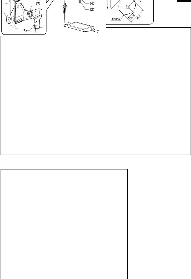
2. Connecting rod
(6) Connecting rod
(7) Nut
0478D
2. INSTALLATION
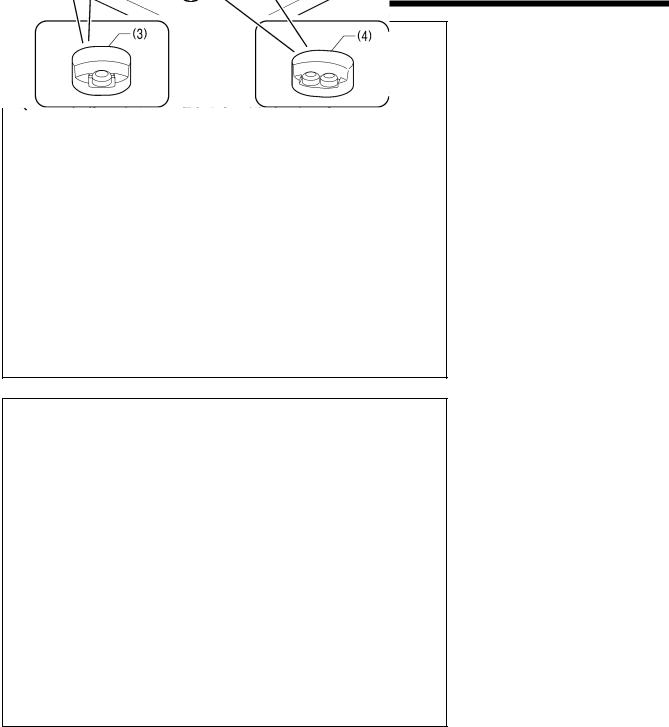
3. Rubber cushions
(1)Rubber cushions [2 pcs]
(2)Nails [4 pcs]
(3)Head cushions (left) [2 pcs]
(4)Head cushions (right) [2 pcs]
0479D
4. Machine head
(1)Hinges [2 pcs]
(2)Machine head
(3)Head rest
NOTE:
Bind the cords together and pass them through the cord hole
Tap the head rest (3) securely into the table hole. If the head rest (3) is not pushed in as far as it will go, the machine head will not be sufficiently stable when it is tilted back.
0480D
2. INSTALLATION
0481D 5. Knee lifter plate
<Knee lifter adjustment>
1. Turn the machine pulley so that the feed dog is below the top of the needle plate.
2. Lower the presser foot (1) by using the lifting lever (2).
3. Loosen the nut (3).
4. Turn the screw (5) to adjust so that the amount of play in the knee lifter is approximately 2 mm when the knee lifter plate (4) is gently pressed.
5. Securely tighten the nut (3).
6. Loosen the nut (6).
7. Turn the adjusting screw (8) to adjust so that the presser foot (7) is at the desired position within a distance of 13 mm of the needle plate when the knee liter plate is fully pressed.
8. After adjustment is completed, securely tighten the nut
(6).
Within 13 mm
0482D
2. INSTALLATION
2-3. Lubrication
 CAUTION
Do not connect the power cord until lubrication has been completed, otherwise the machine may operate if the treadle is depressed by mistake, which could result in injury.
Be sure to wear protective goggles and gloves when handling the lubricating oil, so that it does not get into your eyes or onto your skin.
If care is not taken, inflammation can result. Furthermore, do not drink the lubricating oil. Diarrhea or vomiting may result.
Keep the oil out of the reach of children.
When cutting the nozzle of the oil tank, hold the base of the nozzle securely.
If you hold the end of the nozzle, injury from the scissors may result.
The sewing machine should always be lubricated and the oil supply replenished before it is used for the first time, and also after long periods of non-use.
1. Hold the base of the nozzle of the accessory oil tank (1), and use scissors to cut about half-way along the straight section (A) of the nozzle.
2. Loosen and remove the nozzle, and then remove the seal
(2).
3. Tighten the nozzle.
4. Tilt back the machine head.
5. Remove the rubber cap (3), and pour lubricating oil into the oil tank (4) until it reaches the upper reference line (5). (Approx. 150 ml)
6. Replace the rubber cap (3).
7. Return the machine head to its original position.
NOTE:
When the machine head is tilted back at times such as the following, lubricating oil may leak out from the oil pan (6). 1) If the machine head is tilted back immediately after
sewing;
2) If the machine head is tilted back a long way when the head rest has been removed;
3) If lubricating oil is added until the oil level goes above the upper reference line (5) on the oil tank (4).
<Lubrication oil replenishment interval>
If the oil level drops below the lower reference line (7) on the oil tank (4), be sure to replenish the oil.
0483D
2. INSTALLATION
2-4. Connecting the cords
 CAUTION
Contact your Brother dealer or a qualified electrician for any electrical work that may need to be done.
Do not connect the power cord until all cords have been connected.
The machine may operate if the treadle is depressed by mistake, which could result in injury.
When securing the cords, do not bend the cords excessively or fasten them too hard with staples, otherwise there is the danger that fire or electric shocks could occur.
Be sure to connect the ground. If the ground connection is not secure, you run a high risk of receiving a serious electric shock, and problems with correct operation may also occur.
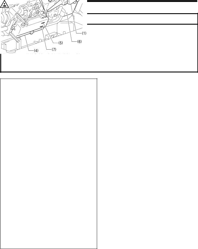
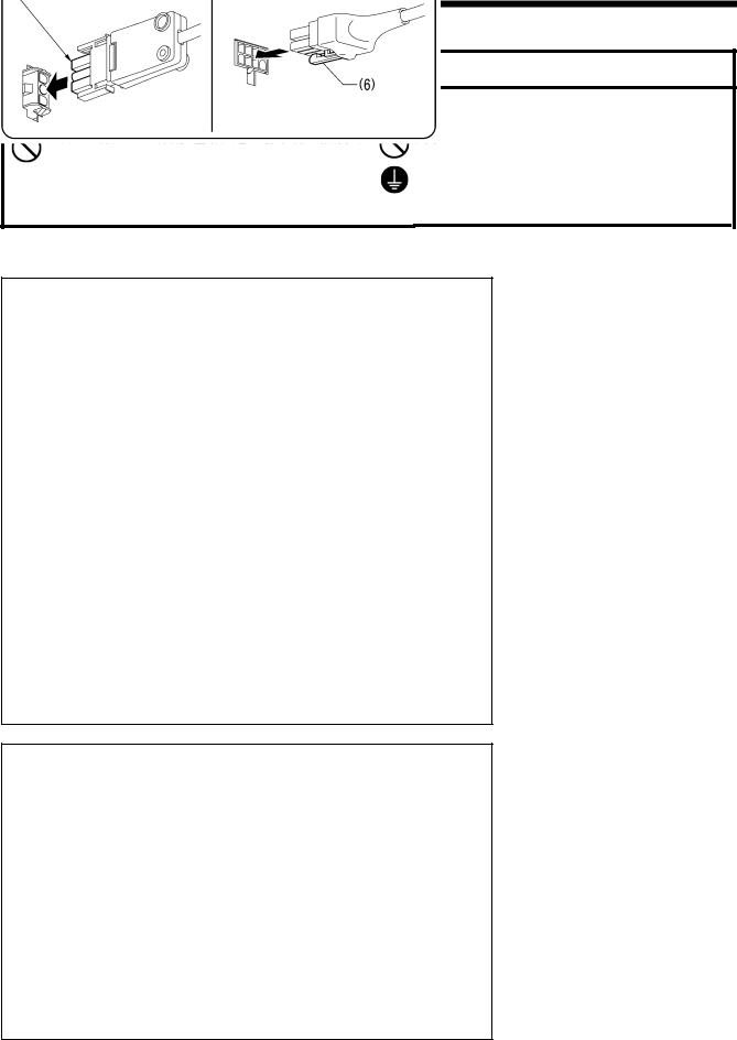
2-4-1. Connecting the cords
0586D 1. Cords
(1) 8-pin operation panel connector
(2) 10-pin resolver connector
(3) 12-pin solenoid connector
(4) 4-pin motor connector
(5) 3-pin power supply connector
|
Align the flat edges |
Lower the tab (6). |
Push in securely until the tabs (6) engage.
Ground symbol
Green and yellow wire (ground wire)
2.Ground wire
(1)Ground wire
(2)Screw
(3)Power cord
1.Attach an appropriate plug to the power cord (3). (The green and yellow wire is the ground wire.)
2.Insert the power plug into a properly-grounded electrical outlet.
NOTE:
For Europe specifications, Americas 220 V specifications and 100 V/400 V system specifications, refer to “2-4-2. Other cords”.
0587D
 Loading…
-
Страница 1
S-7000DD INSTRUCTION MANUAL Please read this manual before using the machine. Please keep this manual within easy reach for quick reference. SINGLE NEEDLE STRAIG HT LOCK STITCHER WITH THREAD TRIMMER[…]
-
Страница 2
S-7000DD Thank you very much for buying a BROTHER sewing machine. Bef ore using your new machine, please read the safety instructions and the ex planations given in the instruction manual. With industrial sewing machines, it is normal to carry out work while positioned directly in front of moving part s such as the needle and thread take-up , and c[…]
-
Страница 3
SAFETY INSTRUCTIONS [1] Safety indications and the ir meanings This instruction manual and the indications and sy mbols that are used on the machine i tself are provided in order to ensure safe operation of this machine and to prevent a ccidents and injury to yourself or other people. The meanings of these indications and symbols are given below. I[…]
-
Страница 4
[2] Notes on safety DANGER Wait at least 5 minutes after turning off the power sw it ch and disconnecting the power cord from the w all outlet before opening the cover of t he control box. Touching areas where high volt ages are present can result in severe injury. WARNING Do not allow any liquids to get onto this sew ing machine, otherwise fire, e[…]
-
Страница 5
CAUTION Sewing This sewing machine should only be used b y operators who have received the necessary training in safe use beforehand. The sewing machine should not be used for any applications other than sewing. Be sure to wear protective goggles when using the machine. If goggles are not worn, ther e is the danger that if a needle breaks, parts of[…]
-
Страница 6
[3] Warning labels The following warning labels appear on the sewing machine. Please follow the instructions on the labels at all times w h en using the machine. If the labels have been removed o r are difficult to read, please cont act your nearest Brother dealer. 1 2 Touching areas where high voltages are p resent can result in severe injury . Tu[…]
-
Страница 7
Control box Oil tank Transformer box (100 V/400 V system only) 0591D S-7000DD v[…]
-
Страница 8
CONTENTS 1. MACHINE SPECIFICATIONS ……………… 1 2. INSTALLATION …………………………………….. 2 2-1. Table processing diagram ……………………….. 3 2-2. Installati on ……………………………………………. 3 2-3. Lubrication ……………………………………………. 6 2-4. Connecting the cor[…]
-
Страница 9
S-7000DD S-7000DD[…]
-
Страница 10
S-7000DD 1. MACHINE SPECIFICATIONS 1 1 . MACHINE SPECIFICA TIONS 3 4 Quick reverse ○ ○ Thread wiper ○ 3 3A 5 0540D Use For light to medium-weight materials For medium-weight materials For heavy-weight materials Max. sewing speed 4,500 sti/mi n 4,500 sti/min 4,000 sti/min Sewing speed at the time o f shipment 4,000 sti/min Start backtacking an[…]
-
Страница 11
S-7000DD 2. INSTALLATION 2 2 . INST ALLA TION C A U T I O N Machine installation should only be carried out by a qualified technician. Contact your Brother dealer or a qualified electrician for any electrical work that ma y need to be done. The sewing machine weighs approximately 32 kg (70lb). The installation should be carried out by two or more p[…]
-
Страница 12
S-7000DD 2. INSTALLATION 3 2-1 . Table processing diagram ・ The top of the table should be 40 mm in thickness and s hould be strong enough to hold the weight and with-stand the vibration of the sewing machine. ・ Drill holes as indicated in the illustration below . Control box mounting hole Cotton stand hole Head rest hole Cord hole 0592D 2-2 . […]
-
Страница 13
S-7000DD 2. INSTALLATION 4 3. Rubber cushions (1) Rubber cushions [2 pcs] ) Rubber cushions [2 pcs] (2) Nails [4 pcs] (2) Nails [4 pcs] (3) Head cushions (left) [2 pcs] (3) Head cushions (left) [2 pcs] (4) Head cushions (right) [2 pcs] (4) Head cushions (right) [2 pcs] 4. Machine head 4. Machine head (1) Hinges [2 pcs] (1) Hinges [2 pcs] (2) Machin[…]
-
Страница 14
S-7000DD 2. INSTALLATION 5 5. Knee lifter plate <Knee lifter adjustmen t> 1. Turn the machine pulley so that the feed dog is below the top of the needle plate. 2. Lower the presser foot (1) by using the lifting lever (2). 0481D 3. Loosen the nut (3). 4. T urn the screw (5) to adjust so that the amo unt of play in the knee lifter is approximat[…]
-
Страница 15
S-7000DD 2. INSTALLATION 6 2-3 . Lubrication CAUTION Do not connect the power cord until lubrication has been co mpleted, otherw ise the machine may operate if the treadle is depressed by mistake, which could result in injury. Be sure to wear protective goggles and gloves when handling the lubric ating oil, so that it does not get into your eyes or[…]
-
Страница 16
S-7000DD 2. INSTALLATION 7 2-4 . Connecting the cords C A U T I O N Contact your Brother dealer or a qualified electrician for any electrical work that ma y need to be done. Do not connect the power cord until all cords have been connected. The machine may operate if the treadle is depressed by mistake, which could result in injury. When securing t[…]
-
Страница 17
S-7000DD 2. INSTALLATION 8 2-4-2 . Other cor ds For Europe specifications, Amer icas 220V specifications and 100 V/400 V system specifications , connect the cords according to the respective specifications. <Europe s pecificatio ns> (1) Filter box (2) Screws [4 pcs] (3) Connector (4) CE bush plate (5) Screws [2 pcs] (6) CE D cord cover (7) Sc[…]
-
Страница 18
S-7000DD 2. INSTALLATION 9 3. Install the cores (10) in the tw o places shown in the illustration. 0588D (10) Core [2 pcs] (11) Screws [2 pcs] (12) Washers [2 pcs] (13) Nuts [2 pcs][…]
-
Страница 19
S-7000DD 2. INSTALLATION 10 <For Americas 220V specifications> (1) Power switch (2) Screws [2 pcs] (3) 3-pin power supply connector (4) Power cord (5) Staples [5 pcs] 1. Attach an appropriate plug to the power cord (4). (The green and yellow wire is the ground wire.) 2. Insert the power plug into a properly-grounded electrical outlet. Operato[…]
-
Страница 20
S-7000DD 2. INSTALLATION 11 <For 100V/400V system specifications> (1) Power s witch (2) Screws [2 pcs] Operato r 4145M (3) Transformer box (4) Transformer box plates [2 pcs] (5) Screw [ with washer] (6) 3-pin power supply connector (7) Staples [5 pcs] (8) Cord clamps [2 pcs] (9) Power cord 1. Attach an appropriate plug to the power cord (9). […]
-
Страница 21
S-7000DD 3. USING THE OPERATION PA NEL (BASIC OPERATIONS) 12 3 . USING THE OPERA TION P ANEL (BASIC OPERA TIONS) 3-1 . Names and functions ・ The operation panel keys cannot be operated while sewing is in progress. Select the keys and set the number of stitches before startin g sewing. ・ In the case of keys w ith indicators, the indicator illumi[…]
-
Страница 22
S-7000DD 3. USING THE OPERATION PA NEL (BASIC OPERATIONS) 13 Power indicator 0489D (7) Thread trimming disable/F1 key When this key is pressed so that the indica tor illuminates, the sewing machine stops in the needle up position without thread trimming being carried out even if the treadle is depressed backward. (8) Slow start/F2 k ey When this ke[…]
-
Страница 23
S-7000DD 3. USING THE OPERATION PA NEL (BASIC OPERATIONS) 14 3-2 . Sewing start and end backtack stitches 0841M 1 Setting start backtack stitches 2 Setting end backtack stitches 3 Start backtacking is carried out. After it has fi nished, normal sew ing continues for as long as the treadle remains depressed. NOTE: If the treadle is returned to the n[…]
-
Страница 24
S-7000DD 3. USING THE OPERATION PA NEL (BASIC OPERATIONS) 15 3-3 . Sewing continuous backtack stitches 3655M 1 Setting continuous backtack stitches 2 If the treadle is simply depressed continuously , the number of stitches set for A, B, C and D will be sewn in a single cycle, the thread will be trimmed automatical ly and then the needle bar will st[…]
-
Страница 25
S-7000DD 4. USING THE OPERATION PA NEL (ADVA NCED OPERATIONS) 16 4 . USING THE OPERA TION P ANEL (ADV ANCED OPERA TIONS) The operations described in this section should only be carried out by a technician. 4-1 . Switching the 4-column display ・ T he 4-column data in the display can be changed to one of the following three statuses each time the S[…]
-
Страница 26
S-7000DD 4. USING THE OPERATION PA NEL (ADVA NCED OPERATIONS) 17 4-2-2 . Setting the start backtack sewing speed 1 Press the SEL key so that the SPEED indicator is illuminated. ・ The maximum sewing speed setting value will appear in the four columns of the display. 2 Press the FUNC key . ・ The ABCD indicator will illuminate and the start backta[…]
-
Страница 27
S-7000DD 4. USING THE OPERATION PA NEL (ADVA NCED OPERATIONS) 18 4-3 . Setting the counters The lower thread counter, thread trimming counter and needle replacement counter can be display ed. The three counters can be operated at the same time. 4-3-1 . Lower thread counter The lower thread counter can be used to let you know approximately how much […]
-
Страница 28
S-7000DD 4. USING THE OPERATION PA NEL (ADVA NCED OPERATIONS) 19 4-3-2 . Thread trim ming counter The lower thread counter can be used to let you know approximately how many items can be sewn. 1 Press the SEL key so that the COUNT indicator is illuminated. ・ The lower thread counter value will appear in the four columns of the display. 2 When the[…]
-
Страница 29
S-7000DD 4. USING THE OPERATION PA NEL (ADVA NCED OPERATIONS) 20 4-3-3 . Needle replacement counter <Setting the needle replacement counter initial value> 1 Press the SEL key so that the COUNT indicator is illuminated. ・ The lower thread counter value will appear in the four columns of the display. 2 When the FUNC key is pressed tw o times,[…]
-
Страница 30
S-7000DD 4. USING THE OPERATION PA NEL (ADVA NCED OPERATIONS) 21 4-4 . Setting basic functions If you turn on the power switch w hile pressing the thread tri mming disable/F1 key , you can then make the following settings. Setting item Four colum ns display Initial v alue Reference item Needle stop position Updn Needle down stop Refer to”4-4-1”[…]
-
Страница 31
S-7000DD 4. USING THE OPERATION PA NEL (ADVA NCED OPERATIONS) 22 4-4-2 . Correction sewing When correction sewing is enabled, sewing will be carried out at sl ow speed (220 sti/min) w hile t he actuator switch is being pressed when the sewing machine is stopped. 1 Activating setting mode (While pressing the thread trimming disable/F1 key , turn on […]
-
Страница 32
S-7000DD 4. USING THE OPERATION PA NEL (ADVA NCED OPERATIONS) 23 4-4-3 . Setting thread wiping The initial setting value is ON. If the thread wiper is connected but thread w iping is not to be carried out, change this setting to OFF. 1 Activating setting mode (While pressing the thread trimming disable/F1 key , turn on the power switch.) 2 Selectin[…]
-
Страница 33
S-7000DD 4. USING THE OPERATION PA NEL (ADVA NCED OPERATIONS) 24 4-5 . Adjusting the needle up stop position 1 (While pressing the key (1) , turn on the pow er switch.) “MorG” will appear in the display (2). 2 Selecting “UPoS” 3 Needle up stop position setting ・ If the D key is pressed, the setting value will increase and the needle up st[…]
-
Страница 34
S-7000DD 4. USING THE OPERATION PA NEL (ADVA NCED OPERATIONS) 25 4-6 . Resetting all settings to their defaults If the sewing machine stops operating normally, the cause ma y be that an incorrect setting may have been made for the memory data by means of memory switches, for instance. In such cases, it may be possible to restore normal operation by[…]
-
Страница 35
S-7000DD 5. CLEANING 26 5 . CLEANING CAUTION Turn off the power switch before carrying out cleaning. The machine may operate if the treadle is depress ed by mistake, which could result in injury. Be sure to w ear protective goggles and gloves when handling the lubricating oil and grease, so that the y do not get into your eyes or onto your skin, ot[…]
-
Страница 36
S-7000DD 6. REPLACING THE FIXED KNIFE AND MOVABLE KNIFE 27 6 . REPLACING THE FIXED KNIFE AND MOVABLE KNIFE CAUTION Replacement of parts should only be carried out by a qualified technician. Turn off the power switch and disconnect the pow er cord from the wall outlet before r eplacing any parts, otherwise the machine may operate if the treadle is p[…]
-
Страница 37
S-7000DD 7. STANDARD A DJUSTMENTS 28 7 . ST ANDARD ADJUSTMENTS CAUTION Maintenance and inspection of the sew ing machine should only be carried out by a qualified technician. Ask your Brother dealer or a qualified electrician to carry out any maintenance and inspection of the electrical system. If any safety devices have been removed, be absolutely[…]
-
Страница 38
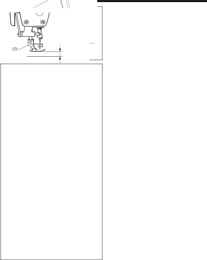
S-7000DD 7. STANDARD A DJUSTMENTS 29 7-2 . Adjusting the presser foot height The standard height of the presser foot (1) is 6 mm w hen the presser foot (1) is raised by means of the lifti ng lever (2). 1. Loosen the nut (3) of the adj ustment screw (4), and then turn the adjustment screw (4) so that there is no pressure applied to the presser foot.[…]
-
Страница 39
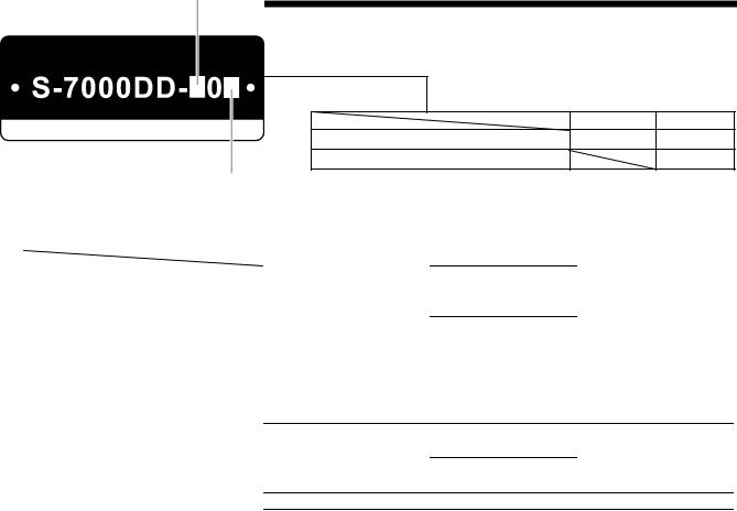
S-7000DD 7. STANDARD A DJUSTMENTS 30 7-3 . Adjusting of the feed dog height The standard height of the feed dog (1) when it is raised as far as possible above the surfac e of the needle plate is 0.8 mm for -[]03 specifications, 1.0 mm for -[]03A specifications and 1.2 mm for -[]05 specifications. Becomes highe r Becomes lowe r 0543 D <-[]03> […]
-
Страница 40
S-7000DD 7. STANDARD A DJUSTMENTS 31 7-5 . Adjusting the needle bar height Reference line (a), which is the second line from the bottom of the needle bar (1) (fourth line from the bottom when using a DA x 1 needle) should be aligned with the lower edge of the needle bar bush D (2) as shown in the illustration when the needle bar (1) is at its lowes[…]
-
Страница 41
S-7000DD 7. STANDARD A DJUSTMENTS 32 7-7 . Adjusting the needle and rotary hook timing The tip of the rotary hook (3) should be aligned with the center of the needle (4) when the needle bar (1) moves up 1.8 mm (2.2 mm for –[]03A and –[]05 specifications) from its lowest position to the positio n where reference line (b) is aligned with the lowe[…]
-
Страница 42
S-7000 33 DD 7. STANDARD A DJUSTMENTS 7-8 . Adjusting the rotary hook lubrication amount CAUTION Be careful not to touch y our fingers or the lubrication amount check sheet against moving parts such a s the rotary hook or the feed mechanism when checki ng the amount of oil supplied to t he rotary hook, otherwise injury may result. Use the following[…]
-
Страница 43
S-7000DD 8. TROUBLESHOOTING 34 8 . TROUBLESHOOTING ・ Please check the following points before calling for repairs or service. ・ If the following remedies do not fix the probl em, turn off the pow er switch and consul t a qualified technician or the place of purchase. C A U T I O N Turn off the power switch and disconnect the power cord before c[…]
-
Страница 44
S-7000DD 8. TROUBLESHOOTING 35 Problem Possible cause Page 5 Skipped stitches at sewing start Thread unravelling at sewing start ・ Is the thread take-up spring tension too strong? Reduce the tension of the thread take-up spring. ・ Is the thread take-up spri ng operating range too large? Lower the position of the thread take-up spring. ・ Are t[…]
-
Страница 45
S-7000DD 8. TROUBLESHOOTING 36 Problem Possible cause Page 8 Material slippage ・ Is the presser foot pressure too strong? Adjust the presser foot pressure. 9 Lower thread is tangled at the sewing start. Spinning of bobbin during thread trimming ・ Is the bobbin spinning direction correct when the lower thread is being pulled? Set the bobbin so t[…]
-
Страница 46
S-7000DD 8. TROUBLESHOOTING 37 Problem Possible cause Page 13 Broken needles ・ Is the material being pushed or pulled with excessive force during sewing? ・ Is the needle properly installed? If it is incorrect, install the needle correctly. ・ Is the needle bent, is the needle tip broken, or is the ne edle hole blocked? Replace the needle. ・ […]
-
Страница 47
S-7000DD 8. TROUBLESHOOTING 38 8-2 . Error code displays If an error code appears on the operation panel display 1. Make a note of the error c ode and then turn off the power. 2. After the operation panel display has turned off, eliminate the c ause of the error and then turn the power back on. 0538D ・ Items with a “ * ” in the “P age” co[…]
-
Страница 48
S-7000DD 8. TROUBLESHOOTING 39 Error code Possible cause Page E090 Treadle connector is not connected. ・ Is the 3-pin tre adle connector in side the control box disconnected? Turn off the power switch, and then che ck that the 3-pin tr eadle connector is connected to connector P3 on the main PCB. ・ Problem with treadle unit. If there is a broke[…]
-
Страница 49
S-7000DD 8. TROUBLESHOOTING 40 Error code Possible cause Page E150 Motor is overheating. ・ This is displayed when the motor bec omes abnormally hot and the te mperature protection has activated. After the temperature has dropped, turn on the power switch and operate the sewing machine as normal. E151 Problem with motor overheating sensor. ・ The[…]
-
Страница 50
S-7000DD 8. TROUBLESHOOTING 41 Error code Possible cause Page E701 Abnormally high power supply voltage. ・ Does the power supply voltage match t he control box volt age specifications? Check that the voltage matches. Check the connection of the 5-pin transfo rmer connector inside the control box. (220 V AC: P12, 230 V AC: P13) ・ Is the pow er s[…]
-
Страница 51
S-7000DD 9. 7-SEGMENT DISPLAY 42 9 . 7-SEGMENT DISPLA Y 4268M[…]
-
Страница 52
INSTRUCTION MANUAL * Please note that the content s of this manual may differ slightly from the actual product purchased as a result of product imp rovements. S-7000DD SB4299-001 E 2013.05. D (1-1) © 2013 Brother Industries, Lt d. All Rights Reserved. http://www .brother .com/ 1-5, Kitajizoyama, Noda-cho, Kariya 44 8-0803, Japan. This is the origi[…]