
Описание:
Набор Remote Control Smart Robot Car 4WD для Arduino в коробке для начального освоения основ программирования и конструирования в среде Ардуино.
Данный комплект для обучения состоит из набора элементов для сборки робота поможет Вам на практике познакомиться с основными принципами конструирования и программирования Arduino. Набор Remote Control Smart Robot Car 4WD содержит в себе все необходимые для начального изучения Arduino элементы: колёса, платформу сервоприводы и многие другие. Набор будет интересен не только для личного использования, но и будет являться оригинальным и познавательным подарком.
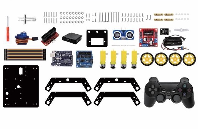
Комплектация:
Thanks for your support on our products, we will continue to provide you better quality and service!
*About keyestudio
Keyestudio is a best-selling brand owned by KEYES Corporation, our product lines range from controller boards, shields and sensor modules to smart car and complete starter kits for Arduino, Raspberry Pi and BBC micro:bit, which designed for customers of any level to learn electronics and programming knowledge. All of our products comply with international quality standards and are greatly appreciated in a variety of different markets throughout the world.
You can obtain the details and the latest information through visiting the following web sites:http://www.keyestudio.com
*References and After-sales Service
1.Download Profile:https://fs.keyestudio.com/KS0428
2.Feel free to contact us please, if there is missing part or you encounter some troubles. Welcome to send email to us:service@keyestudio.com.
We will update projects and products continuously based on your sincere advice.
*Warning
1.This product contains tiny parts(screws, copper pillars), keep it out of reach of children under 7 years old please.
2. This product contains conductive parts (control board and electronic module). Please operate according to the requirements of this tutorial. Improper operation may cause overheating and damage parts. Do not touch and immediately disconnect the circuit power.
*Copyright
The keyestudio trademark and logo are the copyright of KEYES DIY ROBOT co.,LTD. All products under keyestudio brand can’t be copied, sold and resold without authorization by anyone or company. If you’re interested in our items, please contact to our sales representatives: fennie@keyestudio.com
Introduction
Nowadays, technological education such as VR, kids programming, and artificial intelligence, has become mainstream in educational industry. Thereby, people attach importance to STEAM education. Arduino is pretty notable in Maker education.
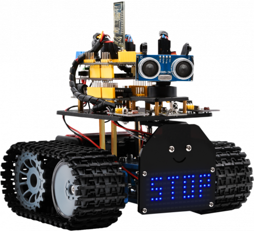
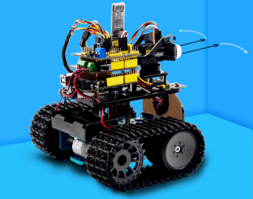
So what is Arduino? Arduino is an open-source electronics platform based on easy-to-use hardware and software. Arduino boards are able to read inputs — light on a sensor, a finger on a button, or a Twitter message — and turn it into an output — activating a motor, turning on an LED, publishing something online. Based on this, Keyestudio team has designed a mini tank robot. The tank robot has a processor which is programmable using the Arduino IDE, to mapped its pins to sensors and actuators by a shield that plug in the processor, it reads sensors and controls the actuators and decides how to operate.
15 learning projects, from simple to complex, will guide you how to make a smart tank robot on you own and introduce the detailed knowledge about sensors and modules.
Simultaneously, it is the best choice if you intend to obtain a DIY robot for learning programming, entertainment and competition requirement.
Features
1.Multi-purpose: Obstacle avoidance, follow, IR remote control, Bluetooth control, light following, ultrasonic follow and displayed face emoticons.
2.Simple assembly: No soldering circuit required, complete assembly easily.
3. High Tenacity:Aluminum alloy bracket, metal motors, high quality wheels and tracks.
4. High extension: expand other sensors and modules through motor driver shield and sensor shield
5. Multiple controls: IR remote control, App control(IOS and Android system)
6.Basic programming:C language code of Arduino IDE.
Specification
- Working voltage: 5v
- Input voltage: 7-12V
- Maximum output current: 2A
- Maximum power dissipation: 25W (T=75℃)
- Motor speed: 5V 200 rpm/min
- Motor drive mode: dual H bridge drive (L298P)
- Ultrasonic induction angle: <15 degrees
- Ultrasonic detection distance: 2cm-400cm
- Infrared remote control distance: 10 meters (measured)
- Bluetooth remote control distance: 50 meters (measured)
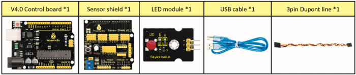
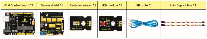
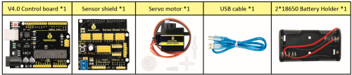
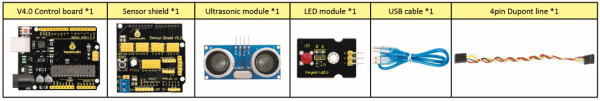
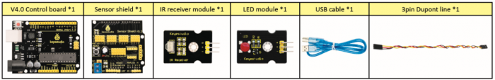
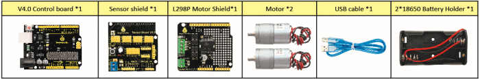
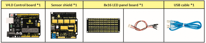
Product List
Make sure no any parts missing please when you get this robot kit. And if it is, please feel free to contact us.
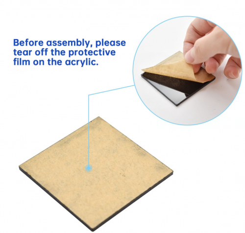
Please tear off the protective film on the acrylic board before mounting the kit
Assembly Guide
Note: Remove the Bluetooth module before uploading test code, otherwise, you will fail to upload test code
Note: Peel the plastic film off the board first when installing the smart car. To be honest, we never intend to send wood to you.
After making an inventory all the parts in this kit, then we need to mount the tank robot. Let’s install smart car in compliance with the following instructions.
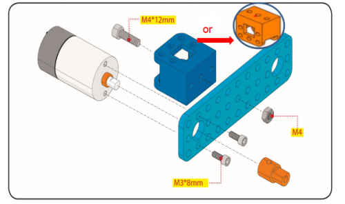
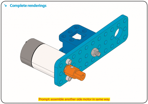
Step 1: Install Bottom Motor
Prepare the parts as follows:
- M4 Nut * 2
- Metal Motor *2
- Metal Holder *2
- Copper Coupler *2
- Blue Supportive Parts *2
- M4*12MM Inner Hex Screw * 2
- M1.5 Hex Key Nickel Plated Allen Wrench *1
- M3 Hex Key Nickel Plated Allen Wrench *1
- M2.5 Hex Key Nickel Plated Allen Wrench *1
- M3*8MM Inner Hex Screw * 4
Step 2: Install Driver Wheel
Prepare the parts as follows:
- M4*12MM Inner Hex Screw * 2
- M4*50MM Inner Hex Screw * 2
- Tank Load-bearing Wheel * 2
- Flange Bearing * 4
- Copper Bush *2
- Caterpillar Band *2
- M4 Self-locking Nut * 2
- M3 Hex Key Nickel Plated Allen Wrench *1
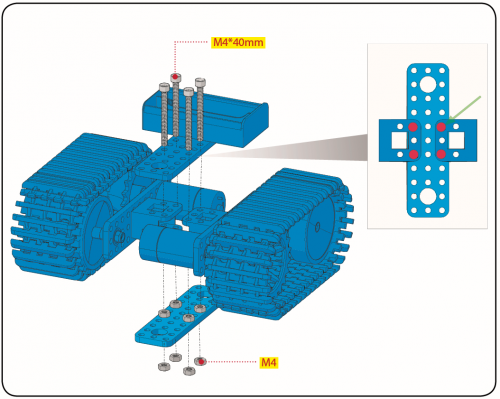
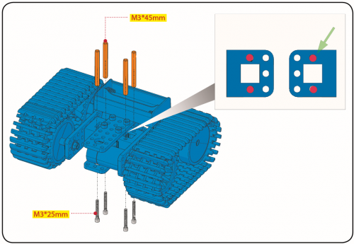
Step 3: Install the Battery Holder
Prepare the parts as follows:
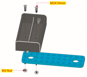
- Battery Holder *1
- M3 Nut * 2
- Blue Metal holder *2
- M4 Nut *8
- M3*10MM Flat Head Screw * 2
- M4*40MM Inner Hex Screw *4
- M2.5 Hex Key Nickel Plated Allen Wrench*1
- M3 Hex Key Nickel Plated Allen Wrench *1
- M3*25MM Inner Hex Screw *4
Finish the mount process. Go to fix the metal holder on the motor wheel with four M4*40MM inner hex screws and four M4 nuts.
Step 4: Mount Acrylic Board and Sensors
- Acrylic Board * 2
- L- type Black Bracket *1
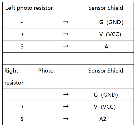
- Photocell Sensor *2
- IR Receiver Module *1
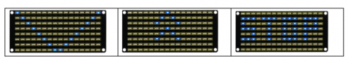
- 8X16 LED Panel *1
- M2 Nut *4
- M3 Nut *10
- M3*6MM Inner Hex Screw * 8
- M2.5 Hex Key Allen Wrench *1
- M3*12MM Round Head Screw *7
- M3*10MM Hexagon Copper Bush *8
- M2*10MM Round Head Screw * 4
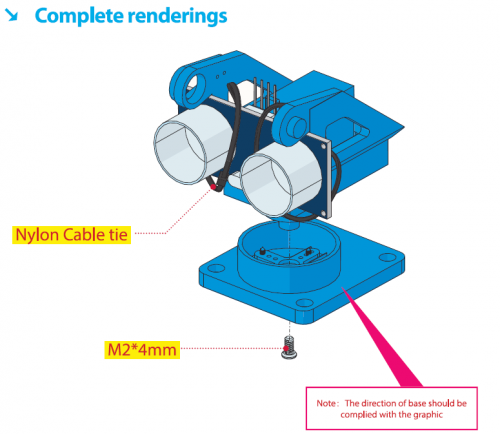
Step 5: Install the Servo Platform
Prepare the parts as follows:
- Servo *1
- Black Gimbal *1
- Cable Tie *2
- M2x8 Round Head Cross Tapping Screw *2
- Ultrasonic Sensor *1
- M2*4 Screw *1
- M1.2*5 Screw *4
Note: for convenient debugging, keep the ultrasonic module straight ahead and the angle of servo motor 90°. Therefore, we need to set servo to 90° before installing the servo platform.
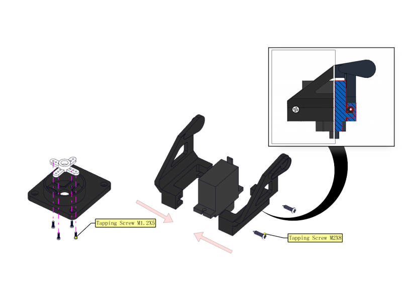
You can find M1.2*5 Screws inside the bag of Plastic Platform.
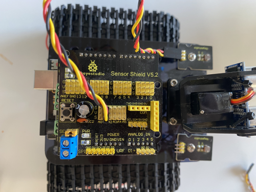
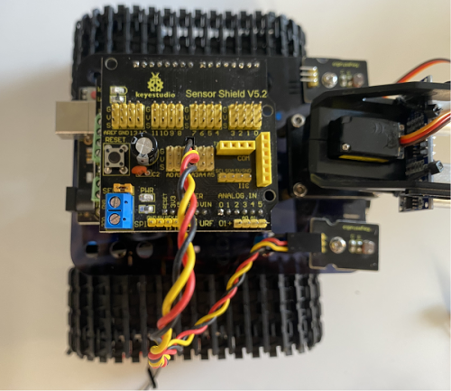
Step 6: Install Sensors and Boards
Prepare the parts as follows:
- M3*6MM Round Head Screw *12
- L298P Shield *1
- V4.0 Board *1
- V5 Sensor Shield *1
- Screwdriver *1
- Bluetooth Module *1
Step 7: Hook-up Guide
Step 8: Wire up LED Panel
Step 9: install all parts of Acrylic plate
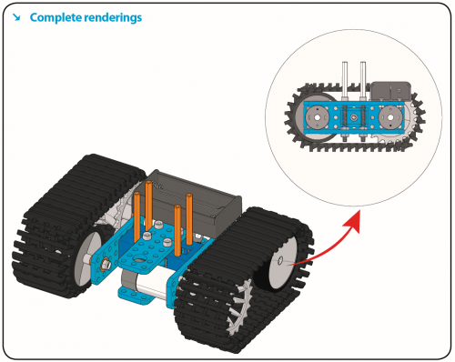
Step 10: Final Renderings
Note: Remove the Bluetooth module before uploading test code, otherwise, you will fail to upload test code.
Install Arduino IDE and Driver
Download software
When we get control board, we need to download Arduino IDE and driver firstly.
You could download Arduino IDE from the official website:
https://www.arduino.cc/, click the SOFTWARE on the browse bar, click “DOWNLOADS” to enter download page, as shown below:
There are various versions for Arduino, just download a suitable version for your system, we will take WINDOWS system as an example to show you how to download and install.
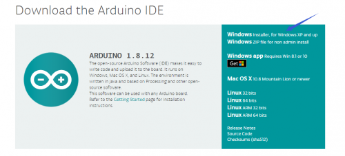
There are two versions for WINDOWS system, one is installed version, another one is download version, you just need to download file to computer directly and unzip it. These two versions can be used normally. Choose one and download on your computer.

You just need to click JUST DOWNLOAD, then click the downloaded file to install it. And when the ZIP file is downloaded, you can directly unzip and start it.
Keyestudio V4.0 Development Board
We need to know keyestudio V4.0 development board, as a core of this smart car.
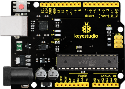
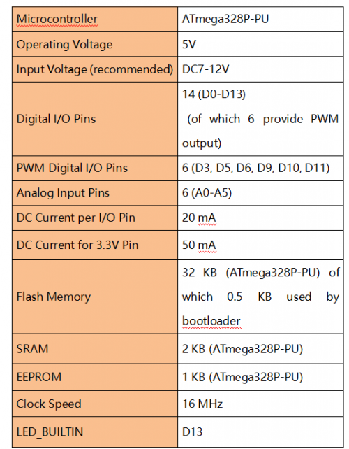
keyestudio V4.0 development board is an Arduino uno-compatible board, which is based on ATmega328P MCU, and with a cp2102 Chip as a UART-to-USB converter.
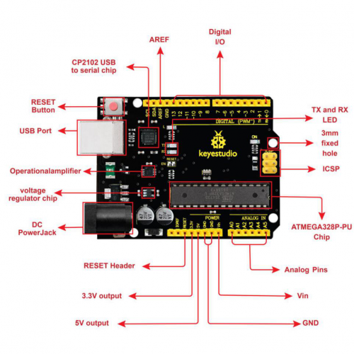
It has 14 digital input/output pins (of which 6 can be used as PWM outputs), 6 analog inputs, a 16 MHz quartz crystal, a USB connection, a power jack, 2 ICSP headers and a reset button.
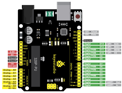
It contains everything needed to support the microcontroller; simply connect it to a computer with a USB cable or power it via an external DC power jack (DC 7-12V) or via female headers Vin/ GND(DC 7-12V) to get started.
Installing driver
Let’s install the driver of keyestudio PLUS control board. The USB-TTL chip on PLUS board adopts CP2102 serial chip. The driver program of this chip is included in Arduino 1.8 version and above, which is convenient. Plug on USB port of board, the computer can recognize the hardware and automatically install the driver of CP2102.
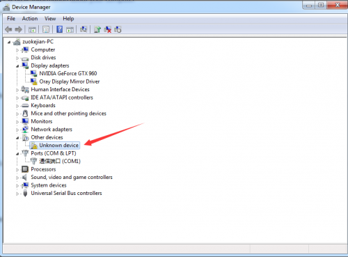
If install unsuccessfully, or you intend to install manually, open the device manager of computer. Right click Computer—— Properties—— Device Manager.
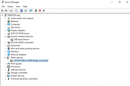
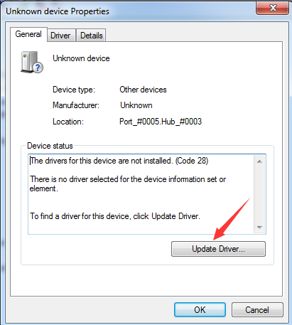
There is a yellow exclamation mark on the page, which implies installing the driver of CP2102 unsuccessfully. Then we double click the hardware and update the driver.
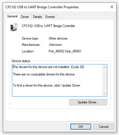
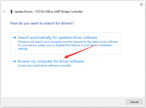
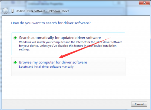
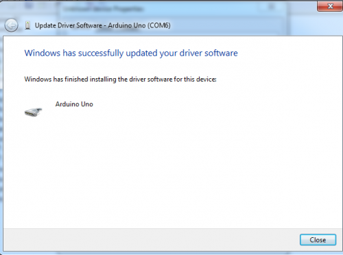
Click “OK” to enter the following page, click “browse my computer for updated driver software”, find out the installed or downloaded ARDUINO software. As shown below:
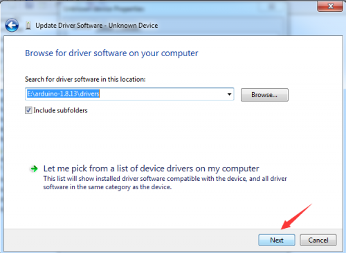
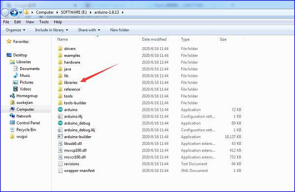
There is a DRIVERS folder in Arduino software installed package(![]() ), open driver folder and you can see the driver of CP210X series chips.
), open driver folder and you can see the driver of CP210X series chips.
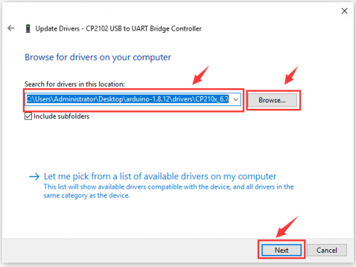
We click “Browse”, then find out the driver folder, or you could enter “driver” to search in rectangular box, then click “next”, the driver will be installed successfully. (I place Arduino software folder on the desktop, you could follow my way)
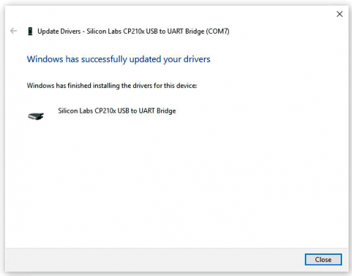
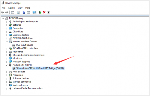
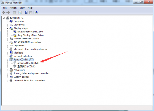
Open device manager, we will find the yellow exclamation mark disappear. The driver of CP2102 is installed successfully.
Install other visions of driver
If your development board is Arduino UNO board, install the driver as follows:
Step 1: Plug in the development board, click Computer—— Properties—— Device Manager, you could see the unknown device is shown.
Step 2: Update the driver
Step 3: click“browse my computer for updated driver software”
Step 4: find out the folder where the ARDUINO software is installed, click drivers folder and tap“Next”
Step 5: the driver is installed successfully.
The device manager shows the serial port of Arduino.
Arduino IDE Setting
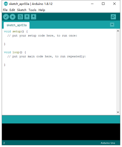
Click icon,open Arduino IDE.
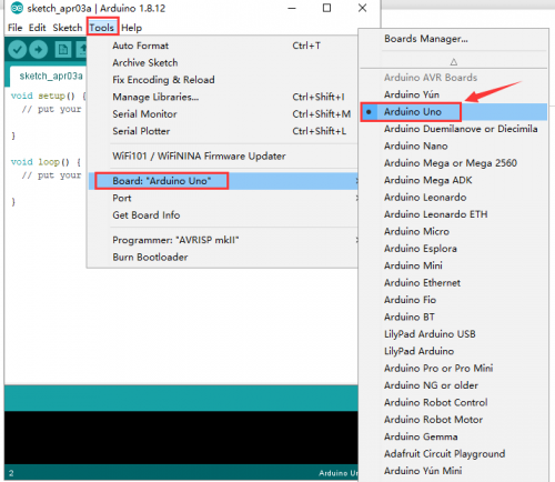
To avoid the errors when uploading the program to the board, you need to select the correct Arduino board that matches the board connected to your computer.
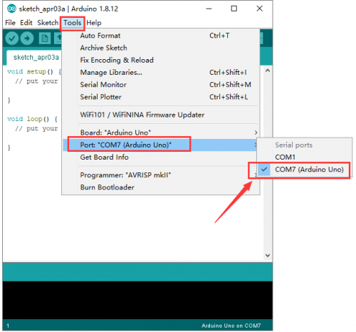
Then come back to the Arduino software, you should click Tools→Board, select the board. (as shown below)
Then select the correct COM port (you can see the corresponding COM port after the driver is successfully installed)
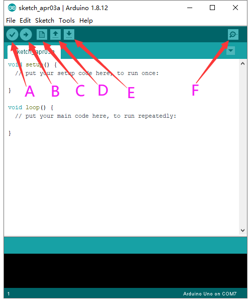
Before uploading the program to the board, let’s demonstrate the function of each symbol in the Arduino IDE toolbar.
A- Used to verify whether there is any compiling mistakes or not.
B- Used to upload the sketch to your Arduino board.
C- Used to create shortcut window of a new sketch.
D- Used to directly open an example sketch.
E- Used to save the sketch.
F- Used to send the serial data received from board to the serial monitor.
Start your first program
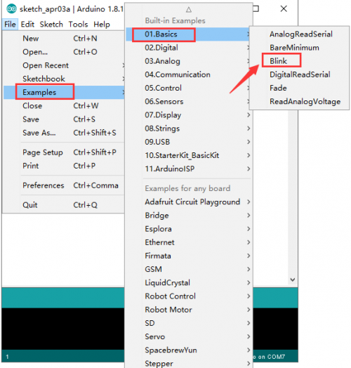
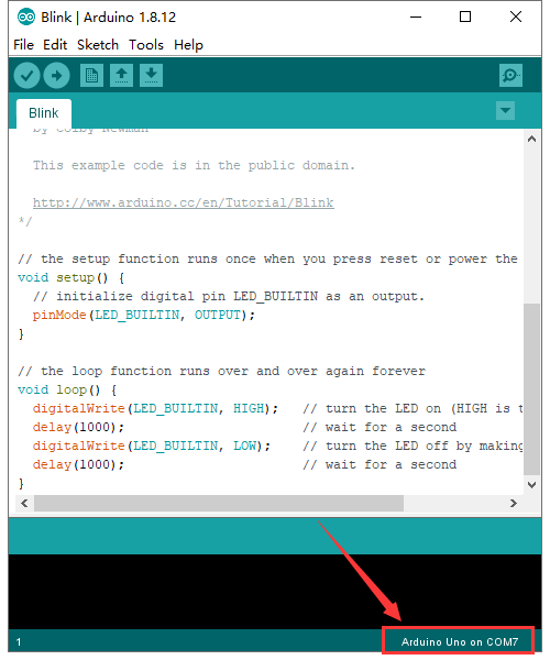
Open the file to select Example, choose BLINK from BASIC, as shown below:
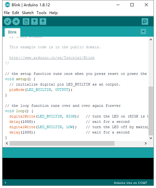
Set board and COM port, the corresponding board and COM port are shown on the lower right of IDE.
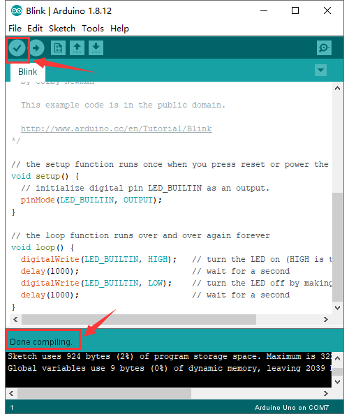
Click ![]() to start compiling the program, check errors.
to start compiling the program, check errors.
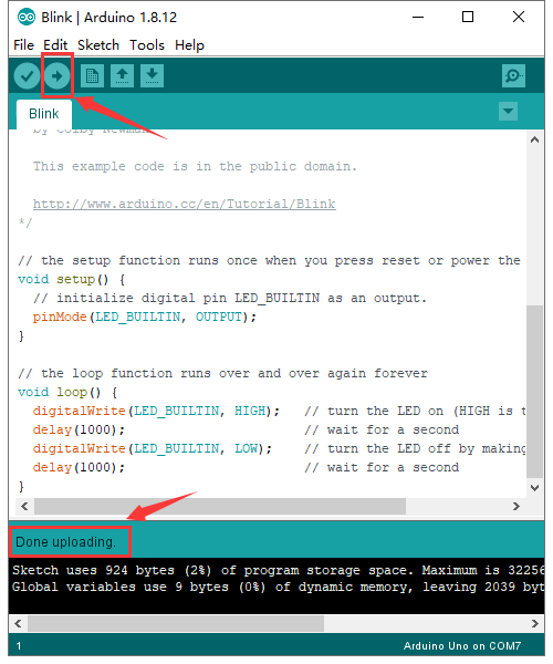
Click ![]() to upload the program, upload successfully.
to upload the program, upload successfully.
Upload the program successfully, the onboard LED lights on for 1s, lights off for 1s. Congratulation, you finish the first program.
How to Add a Library?
What are Libraries ?
Libraries are a collection of code that makes it easy for you to connect to a sensor,display, module, etc.
For example, the built-in LiquidCrystal library helps talk to LCD displays. There are hundreds of additional libraries available on the Internet for download.
The built-in libraries and some of these additional libraries are listed in the reference.
Here we will introduce the most simple way for you to add libraries .
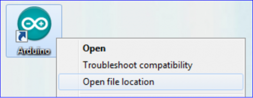
Step 1:After downloading well the Arduino IDE, you can right-click the icon of Arduino IDE.
Find the option «Open file location» shown as below:
Step 2: Enter it to find out libraries folder which is the library file of Arduino.
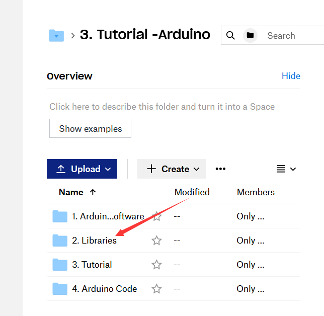
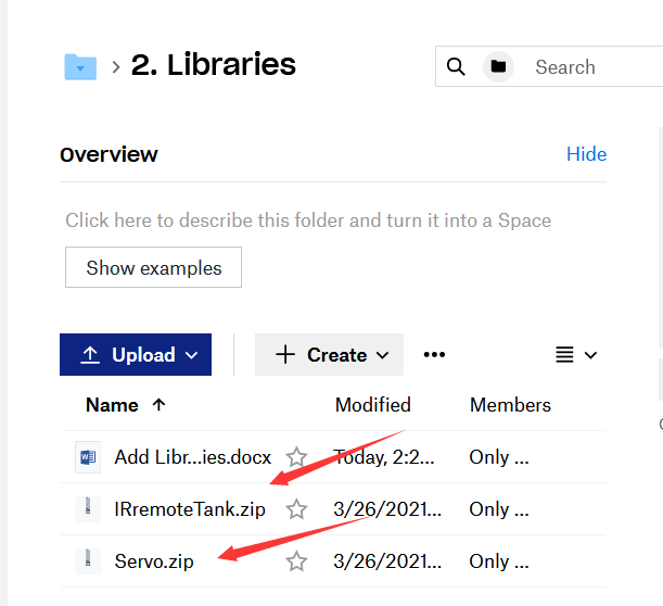
Step 3:Next to find out the“libraries”of tank robot(seen in the link: https://fs.keyestudio.com/KS0428), you just need to replicate and paste into the libraries folder of Arduino IDE.
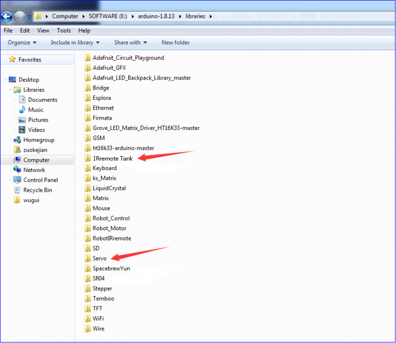
Then the libraries of tank robot are installed successfully, as shown below:
Projects
Project 1: LED Blink
(1)Description
For the starter and enthusiast, this is a fundamental program—LED Blink.
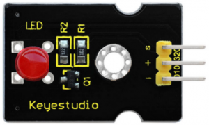
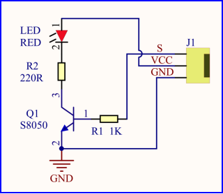
LED, the abbreviation of light emitting diodes, consist of Ga, As, P, N chemical compound and so on. The LED can flash diverse color by altering the delay time in the test code. When in control, power on GND and VCC, the LED will be on if S end is high level; nevertheless, it will go off.
(2)Specification
- Control interface: digital port
- Working voltage: DC 3.3-5V
- Pin spacing: 2.54mm
- LED display color: red
(3)Equipment
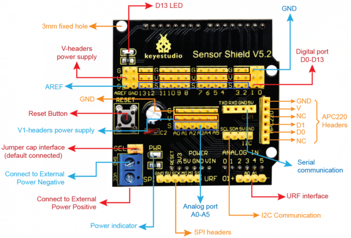
(4) V5 Sensor Shield
There will be troublesome when we combine Arduino development boards with numerous sensors. However, the V5 sensor shield, compatible with Arduino development board, address this problem perfectly. Just stack V5 board on it.
This sensor shield can be inserted into 3pin sensor modules and breaks out some some communication pins, like serial, IIC, and SPI communication as well.
Pins Description
Connection Diagram:
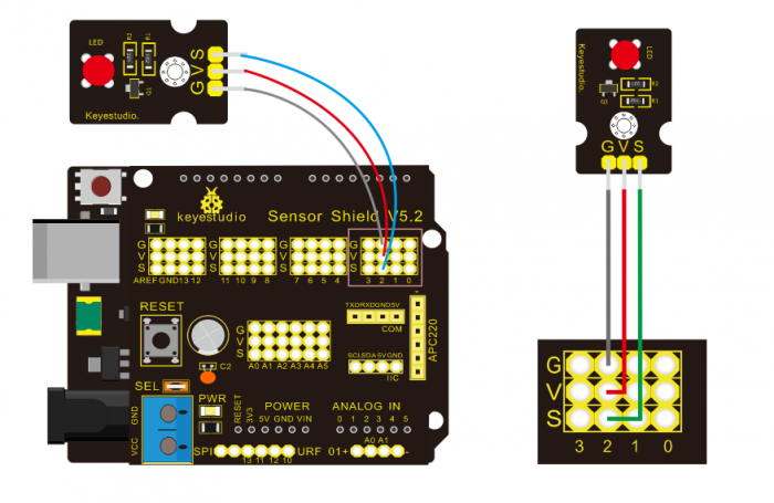
Seen from the above diagram, LED is linked with D2
(5) Test Code
/*
 keyestudio Mini Tank Robot V2
 lesson 1.1
 Blink
 http://www.keyestudio.com
*/
void setup()
 {
    pinMode(2, OUTPUT);// initialize digital pin 2 as an output.
}
void loop() // the loop function runs over and over again forever

{
   digitalWrite(2, HIGH); // turn the LED on (HIGH is the voltage level)
   delay(1000); // wait for a second
   digitalWrite(2, LOW); // turn the LED off by making the voltage LOW
   delay(1000); // wait for a second
}
//****************************************************************
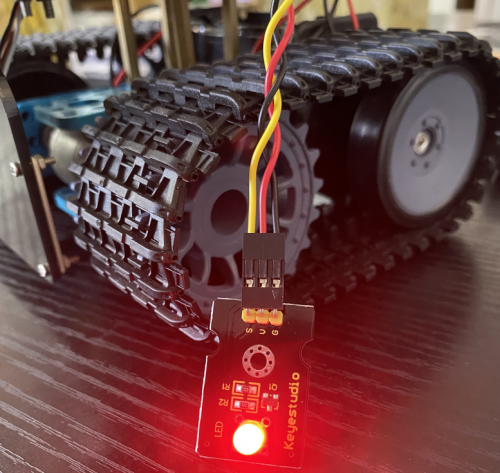
(6) Test Result
(There will be contradict about serial communication between code and Bluetooth when uploading code, therefore, don’t link with Bluetooth module before uploading code.)
Upload the program on the development board, LED flicker with the interval of 1s.
(7)Code Explanation
pinMode(2,OUTPUT) — Set pin2 to OUTPUT
digitalWrite(2,HIGH) — When set pin2 to HIGH level(output 5V) or to LOW level(output 0V)
(8)Extension Practice
We succeed to blink LED. Next, let’s observe what LED will change if we modify pins and delay time.
Connection Diagram
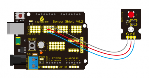
We’ve altered pins and connected LED to D10.
Test Code:
/*
 keyestudio Mini Tank Robot V2
 lesson 1.2
 delay
 http://www.keyestudio.com
*/
void setup() {  // initialize digital pin 10 as an output.
   pinMode(10, OUTPUT);
}
// the loop function runs over and over again forever
void loop() {
   digitalWrite(10, HIGH); // turn the LED on (HIGH is the voltage level)
   delay(100); // wait for 0.1 second
   digitalWrite(10, LOW); // turn the LED off by making the voltage LOW
   delay(100); // wait for 0.1 second
}
//****************************************************************
The LED flickers faster than before through the test result, therefore, pins and delay time affect flash frequency.
Project 2: Adjust LED Brightness
(1)Description
In previous lesson, we control LED on and off and make it blink.
In this project, we will control LED brightness through PWM to simulate breathing effect. Similarly, you can change the step length and delay time in the code so as to demonstrate different breathing effect.
PWM is a means of controlling the analog output via digital means. Digital control is used to generate square waves with different duty cycles (a signal that constantly switches between high and low levels) to control the analog output.In general, the input voltage of port are 0V and 5V. What if the 3V is required? Or what if switch among 1V, 3V and 3.5V? We can’t change resistor constantly. For this situation, we need to control by PWM.
For the Arduino digital port voltage output, there are only LOW and HIGH, which correspond to the voltage output of 0V and 5V. You can define LOW as 0 and HIGH as 1, and let the Arduino output five hundred 0 or 1 signals within 1 second.
If output five hundred 1, that is 5V; if all of which is 1, that is 0V. If output 010101010101 in this way then the output port is 2.5V, which is like showing movie. The movie we watch are not completely continuous. It actually outputs 25 pictures per second. In this case, the human can’t tell it, neither does PWM. If want different voltage, need to control the ratio of 0 and 1. The more 0,1 signals output per unit time, the more accurately control.
(2) Specification
- Control interface: digital port
- Working voltage: DC 3.3-5V
- Pin spacing: 2.54mm
- Display color: red
(3) Equipment

(4) Connection Diagram
(5) Test Code
/*
 keyestudio Mini Tank Robot V2
 lesson 2.1
 pwm
 http://www.keyestudio.com
*/
int ledPin = 10; // Define the LED pin at D10
int value;
void setup ()
{
pinMode (ledPin, OUTPUT); // initialize ledpin as an output.
}
void loop ()
{
for (value = 0; value <255; value = value + 1)
{
analogWrite (ledPin, value); // LED lights gradually light up
delay (5); // delay 5MS
}
for (value = 255; value> 0; value = value-1)
{
analogWrite (ledPin, value); // LED gradually goes out
delay (5); // delay 5MS
}}//**********************************************************
(6)Test Result
Upload test code successfully, LED gradually becomes brighter then darker, like human breath, rather than light on and off immediately.
(7)Code Explanation
When we need to repeat some statements, we could use FOR statement.
FOR statement format is shown below:
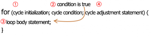
FOR cyclic sequence:
Round 1:1 → 2 → 3 → 4
Round 2:2 → 3 → 4
…
Until number 2 is not established, “for”loop is over,
After knowing this order, go back to code:
for (int value = 0; value < 255; value=value+1){
...
}
for (int value = 255; value >0; value=value-1){
...
}
The two“for”statements make value increase from 0 to 255, then reduce from 255 to 0, then increase to 255,….infinitely loop
There is a new function in the following —— analogWrite()
We know that digital port only has two state of 0 and 1. So how to send an analog value to a digital value? Here,this function is needed. Let’s observe the Arduino board and find 6 pins marked“~”which can output PWM signals.
Function format as follows:
analogWrite(pin,value)
analogWrite() is used to write an analog value from 0~255 for PWM port, so the value is in the range of 0~255. Attention that you only write the digital pins with PWM function, such as pin 3, 5, 6, 9, 10, 11.
PWM is a technology to obtain analog quantity through digital method. Digital control forms a square wave, and the square wave signal only has two states of turning on and off (that is, high or low levels). By controlling the ratio of the duration of turning on and off, a voltage varying from 0 to 5V can be simulated. The time turning on(academically referred to as high level) is called pulse width, so PWM is also called pulse width modulation.
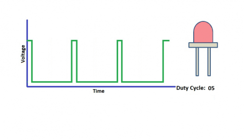
Through the following five square waves, let’s acknowledge more about PWM.
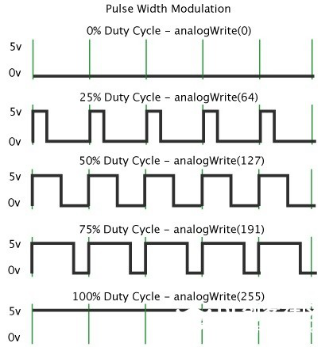
In the above figure, the green line represents a period, and value of analogWrite() corresponds to a percentage which is called Duty Cycle as well. Duty cycle implies that high-level duration is divided by low-level duration in a cycle. From top to bottom, the duty cycle of first square wave is 0% and its corresponding value is 0. The LED brightness is lowest, that is, turn off. The more time high level lasts, the brighter the LED.
Therefore, the last duty cycle is 100%, which correspond to 255, LED is brightest. 25% means darker.
PWM mostly is used for adjusting the LED brightness or rotation speed of motor.
It plays vital role in controlling smart robot car. I believe that you can’t wait to enter next project.
(8) Extension Practice:
Let’s modify the value of delay and remain the pin unchanged, then observe how LED changes.
/*
 keyestudio Mini Tank Robot V2
 lesson 2.2
 pwm-slow
 http://www.keyestudio.com
*/
int ledPin = 10; // Define the LED pin at D10
int value;
void setup ()
{
pinMode (ledPin, OUTPUT); // initialize ledpin as an output.
}
void loop ()
{
for (value = 0; value <255; value = value + 1)
{
analogWrite (ledPin, value); // LED lights gradually light up
delay (30); // delay 30MS
}
for (value = 255; value> 0; value = value-1)
{
analogWrite (ledPin, value); // LED gradually goes out
delay (30); // delay 30MS
}}//**********************************************************
Upload code on the development board and LED gradually get brighter then darker.
Project 3: Photoresistor Sensor
(1)Description
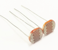
The photoresistor is a special resistor made of semiconductor materials such as CdS or Selenide septum. The surface is also coated with moisture-proof resin, which has a photoconductive effect. It is sensitive to ambient light. Its resistance varies from different light intensities.
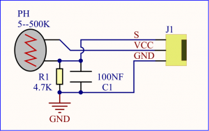
We use the characteristics of the photo-resistor to design the circuit and generate the photo-resistor module.
Connecting the signal pin of photocell module to Analog port, when the stronger the light intensity, the greater the voltage of analog port, the greater the analog value is.
On the contrary, the weaker the light intensity, the smaller the voltage of analog port, the smaller the analog value is.
Based on that, we can use the photocell module to read the analog value, so get the ambient light intensity.
(2)Specification
- Resistance:5K ohm-0.5Mohm
- Interface Type: analog
- Working Voltage: 3.3V-5V
- Easy installation: with screw fixing holes
- Pin spacing: 2.54mm
(3)Equipment
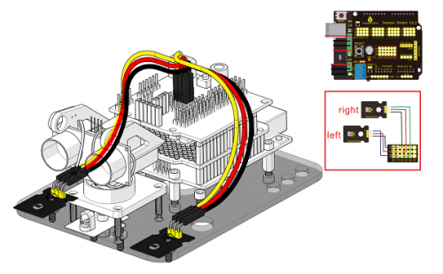
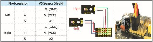
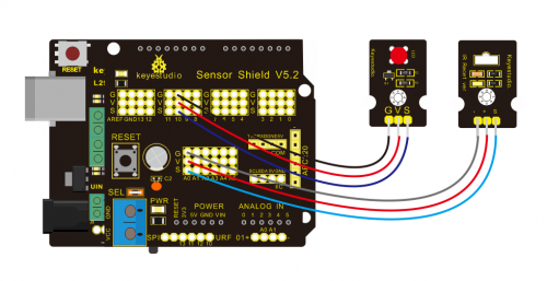
Connection Diagram:
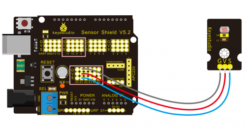
The two photoresistor sensors are linked with A1 and A2, then finish the experiment via photoresistor connected to A1. Then finish the following experiment via photoresistor connected A1. Let’s read its analog value.
(4)Test Code
/*
 keyestudio Mini Tank Robot V2
 lesson 3.1
 photocell
 http://www.keyestudio.com
*/
int sensorPin = A1;    // select the input pin for the photocell
int sensorValue = 0;  // variable to store the value coming from the sensor
void setup() {
Serial.begin(9600);
}
void loop() {
sensorValue = analogRead(sensorPin);  // read the value from the sensor:
Serial.println(sensorValue);  //Serial port prints the resistance value
delay(500);
}
//******************************************************
(5)Test Result
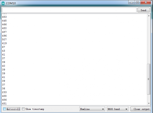
Upload code on development board, open serial monitor, check if its value diminishes when covering photoresistor. However, the value increases when uncovered.
(6)Code Explanation
analogRead(sensorPin):read the analog value of photoresistor via analog ports.
Serial.begin(9600): Initialize the serial port, baud rate of serial communication is 9600
Serial.println : Serial port prints and word wrap.
(7)Extension Practice
We’ve known how to read the value of photoresistor. Let’s combine photoresistor with LED and view the status of LED.
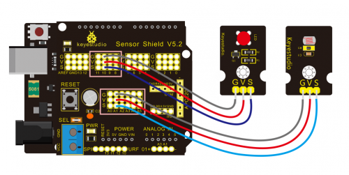
PWM restrains the brightness, so LED is linked with PWM pins, connect LED to pin 10, keep pin of photoresistor unchanged, then design the code:
/*keyestudio Mini Tank Robot V2
lesson 3.2
photocell-analog output
http://www.keyestudio.com
*/
int analogInPin = A1;  // Analog input pin that the photocell is attached to
int analogOutPin = 10; // Analog output pin that the LED is attached to
int sensorValue = 0;        // value read from the pot
int outputValue = 0;        // value output to the PWM (analog out)
void setup() {
Serial.begin(9600);
 }
void loop() {
  // read the analog in value:
  sensorValue = analogRead(analogInPin);
  // map it to the range of the analog out:
  outputValue = map(sensorValue, 0, 1023, 0, 255);
  // change the analog out value:
  analogWrite(analogOutPin, outputValue);
  // wait 2 milliseconds before the next loop for the analog-to-digital
  // converter to settle after the last reading:
 Serial.println(sensorValue);  //serial port prints the value of photoresistor
delay(2);
}
//***************************************************************
Upload code, press it by hand and see the the LED brightness.
Project 4: Servo Control
(1)Description
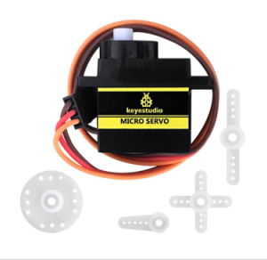
Servo motor is a position control rotary actuator. It mainly consists of housing, circuit board, core-less motor, gear and position sensor. Its working principle is that the servo receives the signal sent by MCU or receiver and produces a reference signal with a period of 20ms and width of 1.5ms, then compares the acquired DC bias voltage to the voltage of the potentiometer and obtain the voltage difference output.
When the motor speed is constant, the potentiometer is driven to rotate through the cascade reduction gear, which leads that the voltage difference is 0, and the motor stops rotating. Generally, the angle range of servo rotation is 0° —180 °
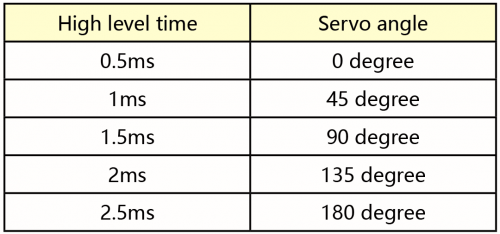
The rotation angle of servo motor is controlled by regulating the duty cycle of PWM (Pulse-Width Modulation) signal. The standard cycle of PWM signal is 20ms (50Hz). Theoretically, the width is distributed between 1ms-2ms, but in fact, it’s between 0.5ms-2.5ms. The width corresponds the rotation angle from 0° to 180°. But note that for different brand motor, the same signal may have different rotation angle.
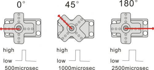
The corresponding servo angles are shown below:
(2)Specification
- Working voltage: DC 4.8V ~ 6V
- Operating angle range: about 180 ° (at 500 → 2500 μsec)
- Pulse width range: 500 → 2500 μsec
- No-load speed: 0.12 ± 0.01 sec / 60 (DC 4.8V) 0.1 ± 0.01 sec / 60 (DC 6V)
- No-load current: 200 ± 20mA (DC 4.8V) 220 ± 20mA (DC 6V)
- Stopping torque: 1.3 ± 0.01kg · cm (DC 4.8V) 1.5 ± 0.1kg · cm (DC 6V)
- Stop current: ≦ 850mA (DC 4.8V) ≦ 1000mA (DC 6V)
- Standby current: 3 ± 1mA (DC 4.8V) 4 ± 1mA (DC 6V)
(3)Equipment
(4)Connection Diagram:
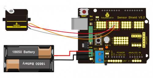
Wiring note: the brown line of servo is linked with Gnd(G), the red line is connected to 5v(V) and orange line is attached to digital 9.
The servo have to be connected to external power, due to its high demand for driving servo current. Generally, the current of development board is not enough. If without connected power, the development board could be burnt.
(5)Test Code1
/*
keyestudio Mini Tank Robot V2
lesson 4.1
Servo
http://www.keyestudio.com
*/
#define servoPin 9  //servo Pin
int pos; //angle variable of servo
int pulsewidth; // pulse width variable of servo
void setup() {
  pinMode(servoPin, OUTPUT);  //set servo pin to OUTPUT
  procedure(0); //set the angle of servo to 0°
}
void loop() {
  for (pos = 0; pos <= 180; pos += 1) { // goes from 0 degrees to 180 degrees
    // in steps of 1 degree
    procedure(pos);              // tell servo to go to position in variable 'pos'
    delay(15);                   //control the rotation speed of servo
  }
  for (pos = 180; pos >= 0; pos -= 1) { // goes from 180 degrees to 0 degrees
    procedure(pos);              // tell servo to go to position in variable 'pos'
    delay(15);
  }
}
// function to control servo
void procedure(int myangle) {
  pulsewidth = myangle * 11 + 500;  //calculate the value of pulse width
  digitalWrite(servoPin,HIGH);
  delayMicroseconds(pulsewidth);   //The duration of high level is pulse width
  digitalWrite(servoPin,LOW);
  delay((20 - pulsewidth / 1000));  // the cycle is 20ms, the low level last for the rest of time
}
//********************************************************************
Upload code successfully, servo swings back in the range of 0° to 180°
There is another guide for restraining servo—- servo library file, the following link of official website is for your reference.
https://www.arduino.cc/en/Reference/Servo
Servo library file
(6)Test Code2
/*
 keyestudio Mini Tank Robot V2
 lesson 4.2
 servo
 http://www.keyestudio.com
*/
#include <Servo.h>
Servo myservo;  // create servo object to control a servo
// twelve servo objects can be created on most boards
int pos = 0;    // variable to store the servo position
void setup() {
  myservo.attach(9);  // attaches the servo on pin 9 to the servo object
}
void loop() {
  for (pos = 0; pos <= 180; pos += 1) { // goes from 0 degrees to 180 degrees
    // in steps of 1 degree
    myservo.write(pos);              // tell servo to go to position in variable 'pos'
    delay(15);                       // waits 15ms for the servo to reach the position
  }
  for (pos = 180; pos >= 0; pos -= 1) { // goes from 180 degrees to 0 degrees
    myservo.write(pos);              // tell servo to go to position in variable 'pos'
    delay(15);                       // waits 15ms for the servo to reach the position
  }
}
//****************************************************************
(7)Test Result
Upload code successfully and power on, servo rotates in the range of 0° to 180°. The result is same. We usually control it by library file.
(8)Code Explanation
Arduino comes with #include <Servo.h> (servo function and statement)
The following are some common statements of the servo function:
1. attach(interface)——Set servo interface, port 9 and 10 are available
3.write(angle)——The statement to set rotation angle of servo, the angle range is from 0° to 180°
3. read()——The statement to read angle of servo, read the command value of “write()”
4. Note: The above written format is “servo variable name, specific statement()”, for instance: myservo.attach(9)
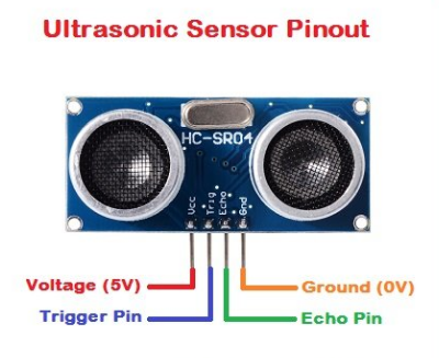
Project 5: Ultrasonic Sensor
(1)Description
The HC-SR04 ultrasonic sensor uses sonar to determine distance to an object like bats do. It offers excellent non-contact range detection with high accuracy and stable readings in an easy-to-use package. It comes complete with ultrasonic transmitter and receiver modules.
The HC-SR04 or the ultrasonic sensor is being used in a wide range of electronics projects for creating obstacle detection and distance measuring application as well as various other applications. Here we have brought the simple method to measure the distance with arduino and ultrasonic sensor and how to use ultrasonic sensor with arduino.
(2)Specification
- Power Supply :+5V DC
- Quiescent Current : <2mA
- Working Current: 15mA
- Effectual Angle: <15°
- Ranging Distance : 2cm – 400 cm
- Resolution : 0.3 cm
- Measuring Angle: 30 degree
- Trigger Input Pulse width: 10uS
(3)Equipment
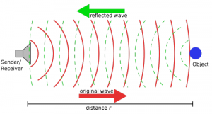
(4)The principle of ultrasonic sensor
As the above picture shown, it is like two eyes. One is transmitting end, the other is receiving end.
The ultrasonic module will emit the ultrasonic waves after trigger signal. When the ultrasonic waves encounter the object and are reflected back, the module outputs an echo signal, so it can determine the distance of object from the time difference between trigger signal and echo signal.
The t is the time that emitting signal meets obstacle and returns.
and the propagation speed of sound in the air is about 343m/s, therefore, distance = speed * time, because the ultrasonic wave emits and comes back, which is 2 times of distance, so it needs to be divided by 2, the distance measured by ultrasonic wave = (speed * time)/2
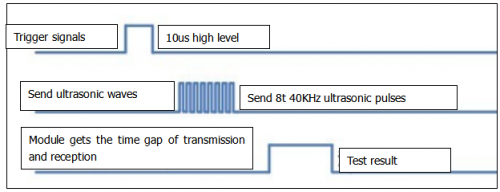
1.Use method and timing chart of ultrasonic module:
Setting the delay time of Trig pin of SR04 to 10μs at least, which can trigger it to detect distance.
2. After triggering, the module will automatically send eight 40KHz ultrasonic pulses and detect whether there is a signal return. This step will be completed automatically by the module.
3. If the signal returns, the Echo pin will output a high level, and the duration of the high level is the time from the transmission of the ultrasonic wave to the return.
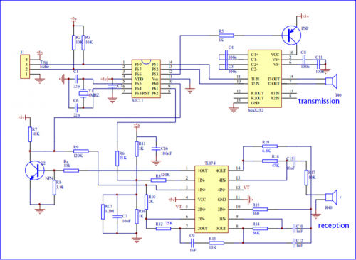
Circuit diagram of ultrasonic sensor:
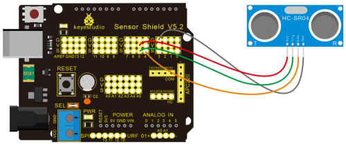
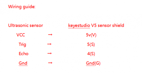
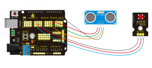
(5)Connection Diagram
(6)Test Code
/*
keyestudio Mini Tank Robot V2
lesson 5
Ultrasonic sensor
http://www.keyestudio.com
*/
int trigPin = 5; // Trigger
int echoPin = 4; // Echo
long duration, cm, inches;
void setup() {
//Serial Port begin
Serial.begin (9600);
//Define inputs and outputs
pinMode(trigPin, OUTPUT);
pinMode(echoPin, INPUT);
}
void loop() {
// The sensor is triggered by a HIGH pulse of 10 or more microseconds.
// Give a short LOW pulse beforehand to ensure a clean HIGH pulse:
digitalWrite(trigPin, LOW);
delayMicroseconds(2);
digitalWrite(trigPin, HIGH);
delayMicroseconds(10);
digitalWrite(trigPin, LOW);
// Read the signal from the sensor: a HIGH pulse whose
// duration is the time (in microseconds) from the sending
// of the ping to the reception of its echo off of an object.
duration = pulseIn(echoPin, HIGH);
// Convert the time into a distance
cm = (duration/2) / 29.1; // Divide by 29.1 or multiply by 0.0343
inches = (duration/2) / 74; // Divide by 74 or multiply by 0.0135
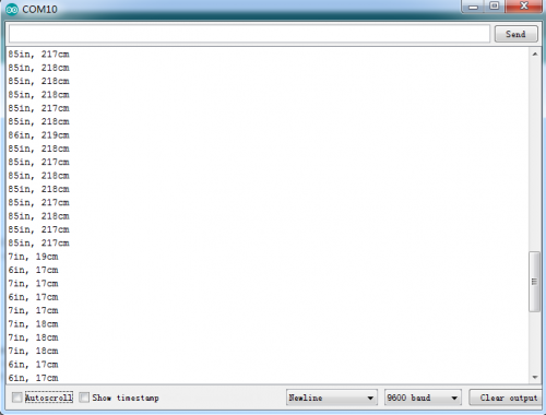
Serial.print(inches);
Serial.print("in, ");
Serial.print(cm);
Serial.print("cm");
Serial.println();
delay(250);
}
//****************************************************************
(7)Test Result
Upload test code on the development board, open serial monitor and set baud rate to 9600. The detected distance will be displayed, unit is cm and inch. Hinder the ultrasonic sensor by hand, the displayed distance value is smaller.
(8)Code Explanation
int trigPin = 5; this pin is defined pin to transmit ultrasonic waves, generally output.
int echoPin = 4; this is defined as the pin of reception, generally input
cm = (duration/2) / 29.1; inches = (duration/2) / 74; by 0.0135
We can calculate the distance by using the following formula:
distance = (traveltime/2) x speed of sound
The speed of sound is: 343m/s = 0.0343 cm/uS = 1/29.1 cm/uS
Or in inches: 13503.9in/s = 0.0135in/uS = 1/74in/uS
We need to divide the traveltime by 2 because we have to take into account that the wave was sent, hit the object, and then returned back to the sensor.
(9)Extension Practice:
We have just measured the distance displayed by the ultrasonic. How about controlling the LED with the measured distance? Let’s try it, connect an LED light module to the D10 pin.
/*
 keyestudio Mini Tank Robot V2
 lesson 5
 Ultrasonic LED
 http://www.keyestudio.com
*/
int trigPin = 5;    // Trigger
int echoPin = 4;    // Echo
long duration, cm, inches;
void setup() {
  //Serial Port begin
  Serial.begin (9600);
  //Define inputs and outputs
  pinMode(trigPin, OUTPUT);
  pinMode(echoPin, INPUT);
}
 void loop()
{
  // The sensor is triggered by a HIGH pulse of 10 or more microseconds.
  // Give a short LOW pulse beforehand to ensure a clean HIGH pulse:
  digitalWrite(trigPin, LOW);
  delayMicroseconds(2);
  digitalWrite(trigPin, HIGH);
  delayMicroseconds(10);
  digitalWrite(trigPin, LOW);
  // Read the signal from the sensor: a HIGH pulse whose
  // duration is the time (in microseconds) from the sending
  // of the ping to the reception of its echo off of an object.
  duration = pulseIn(echoPin, HIGH);
  // Convert the time into a distance
  cm = (duration/2) / 29.1;     // Divide by 29.1 or multiply by 0.0343
  inches = (duration/2) / 74;   // Divide by 74 or multiply by 0.0135
  Serial.print(inches);
  Serial.print("in, ");
  Serial.print(cm);
  Serial.print("cm");
  Serial.println();
  delay(250);
if (cm>=2 && cm<=10)
digitalWrite(10, HIGH);
delay(1000);
digitalWrite(10, LOW);
delay(1000);
}
//****************************************************************
Upload test code to development board and block ultrasonic sensor by hand, then check if LED is on
Project 6: IR Reception
(1)Description
There is no doubt that infrared remote control is ubiquitous in daily life. It is used to control various household appliances, such as TVs, stereos, video recorders and satellite signal receivers. Infrared remote control is composed of infrared transmitting and infrared receiving systems, that is, an infrared remote control and infrared receiving module and a single-chip microcomputer capable of decoding.
The 38K infrared carrier signal emitted by remote controller is encoded by the encoding chip in the remote controller. It is composed of a section of pilot code, user code, user inverse code, data code, and data inverse code. The time interval of the pulse is used to distinguish whether it is a 0 or 1 signal and the encoding is made up of these 0, 1 signals.
The user code of the same remote control is unchanged. The data code can distinguish the key.
When the remote control button is pressed, the remote control sends out an infrared carrier signal. When the IR receiver receives the signal, the program will decode the carrier signal and determines which key is pressed. The MCU decodes the received 01 signal, thereby judging what key is pressed by the remote control.
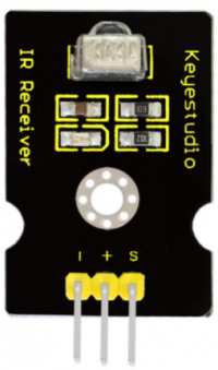
Infrared receiver we use is an infrared receiver module. Mainly composed of an infrared receiver head, it is a device that integrates reception, amplification, and demodulation. Its internal IC has completed demodulation, and can achieve from infrared reception to output and be compatible with TTL signals. Additionally, it is suitable for infrared remote control and infrared data transmission. The infrared receiving module made by the receiver has only three pins, signal line, VCC and GND. It is very convenient to communicate with arduino and other microcontrollers.
(2)Specification
- Operating Voltage: 3.3-5V(DC)
- Interface: 3PIN
- Output Signal: Digital signal
- Receiving Angle: 90 degrees
- Frequency: 38khz
- Receiving Distance: 10m
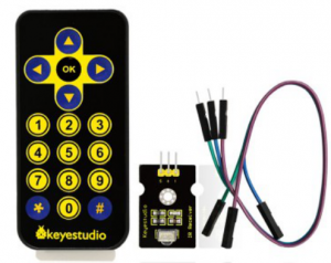
(3)Equipment
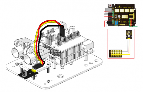
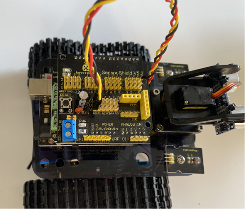
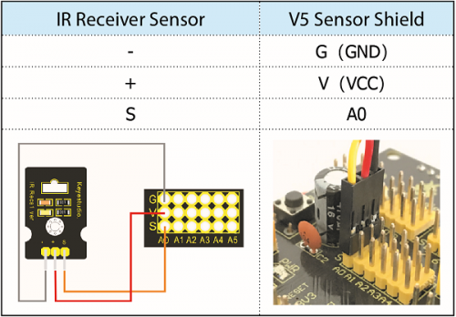
(4)Connection Diagram
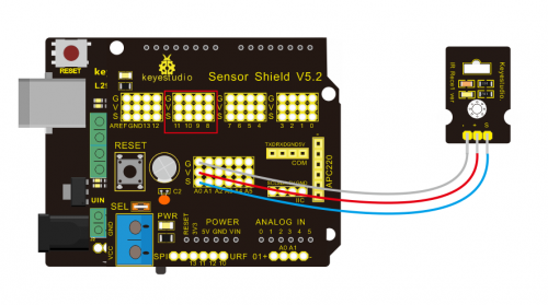
Respectively link “-”、“+” and S of IR receiver module with G(GND), V(VCC)and A0 of keyestudio development board.
Attention: On the condition that digital ports are not available, analog ports can be regarded as digital ports. A0 equals to D14, A1 is equivalent to digital 15.
(5)Test Code
Firstly import library file of IR receiver module(refer to how to import Arduino library file) before designing code.
/*
keyestudio Mini Tank Robot V2
lesson 6
IRremote
http://www.keyestudio.com
*/
#include <IRremoteTank.h>     // IRremote library statement
int RECV_PIN = A0;        //define the pins of IR receiver as A0
IRrecv irrecv(RECV_PIN);
decode_results results;   // decode results exist in the “result” of “decode results”
void setup()
	{
      Serial.begin(9600);
      irrecv.enableIRIn(); //Enable receiver
	}
 void loop() {
	  if (irrecv.decode(&results))//decode successfully, receive a set of infrared signals
	  {
	    Serial.println(results.value, HEX);//Wrap word in 16 HEX to output and receive code
	    irrecv.resume(); // Receive the next value
	  }
	  delay(100);
	}
//*******************************************************
(6)Test Result
Upload test code, open serial monitor and set baud rate to 9600, point remote control to IR receiver and the corresponding value will be shown, if pressing so long, the error codes will appear.
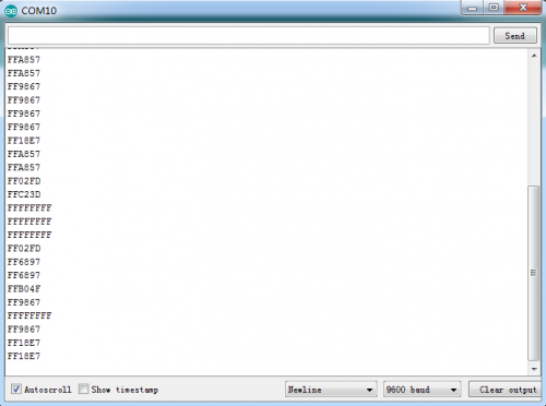
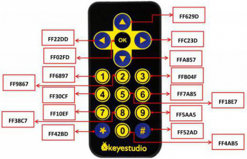
Below we have listed out each button value of keyestudio remote control. So you can keep it for reference.
(7)Code Explanation
irrecv.enableIRIn(): after enabling IR decoding, the IR signals will be received, then function“decode()”will check continuously if decode successfully.
irrecv.decode(&results): after decoding successfully, this function will come back to “true”, and keep result in “results”. After decoding a IR signals, run the resume()function and receive the next signal
(8)Extension Practice
We decoded the key value of IR remote control. How about restrain LED by the measured value? We could operate an experiment to affirm. Attach a LED to D10. When keep the pin of IR receiver unchanged, LED will be on when pressing the key of remote control; press again, LED will be off.
/* keyestudio Mini Tank Robot V2
lesson 6.2
IRremote
http://www.keyestudio.com
*/
#include <IRremoteTank.h>
int RECV_PIN = A0;//define the pin of IR receiver as A0
int LED_PIN=10;//define the pin of LED
int a=0;
IRrecv irrecv(RECV_PIN);
decode_results results;
void setup()
{
  Serial.begin(9600);
  irrecv.enableIRIn(); // Initialize the IR receiver
  pinMode(LED_PIN,OUTPUT);//set LED_pin to OUTPUT
}
void loop() {
  if (irrecv.decode(&results)) {
if(results.value==0xFF02FD &a==0) // according to the above key value, press“OK”on remote control , LED will be controlled
{
    digitalWrite(LED_PIN,HIGH);//LED will be on
a=1;
}
else if(results.value==0xFF02FD &a==1) //press again
{
digitalWrite(LED_PIN,LOW);//LED will go off
a=0;
}
    irrecv.resume(); //receive the next value
  }
}
//*******************************************************
Upload code to development board, press“OK”key on remote control to make LED on and off.
Project 7: Bluetooth Remote Control
(1)Description
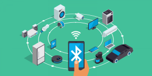
Bluetooth, a simple wireless communication module most popular since the last few decades and easy to use are being used in most of the battery-powered devices.
Over the years, there have been many upgrades of Bluetooth standard to keep fulfil the demand of customers and technology according to the need of time and situation.
Over the few years, there are many things changed including data transmission rate, power consumption with wearable and IoT Devices and Security System.
Here we are going to learn about HM-10 BLE 4.0 with Arduino Board. The HM-10 is a readily available Bluetooth 4.0 module. This module is used for establishing wireless data communication. The module is designed by using the Texas Instruments CC2540 or CC2541 Bluetooth low energy (BLE) System on Chip (SoC).
(2)Specification
- Bluetooth protocol: Bluetooth Specification V4.0 BLE
- No byte limit in serial port Transceiving
- In open environment, realize 100m ultra-distance communication with iphone4s
- Working frequency: 2.4GHz ISM band
- Modulation method: GFSK(Gaussian Frequency Shift Keying)
- Transmission power: -23dbm, -6dbm, 0dbm, 6dbm, can be modified by AT command.
- Sensitivity: ≤-84dBm at 0.1% BER
- Transmission rate: Asynchronous: 6K bytes ; Synchronous: 6k Bytes
- Security feature: Authentication and encryption
- Supporting service: Central & Peripheral UUID FFE0, FFE1
- Power consumption: Auto sleep mode, stand by current 400uA~800uA, 8.5mA during transmission.
- Power supply: 5V DC
- Working temperature: –5 to +65 Centigrade
(3)Equipment

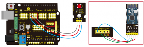
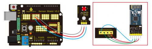
(4)Connection Diagram
- 1. STATE: state test pins, connected to internal LED, generally keep it unconnected.
- 2. RXD: serial interface, receiving terminal.
- 3. TXD: serial interface, transmitting terminal.
- 4. GND: Ground.
- 5. VCC: positive pole of the power source.
- 6. EN/BRK: break connect, it means breaking the Bluetooth connection, generally, keep it unconnected.
(5)Test Code
/*
 keyestudio Mini Tank Robot v2.0
 lesson 7.1
 bluetooth
http://www.keyestudio.com
*/

char ble_val; //character variable: save the value of Bluetooth reception

void setup() {
  Serial.begin(9600);
}
void loop() {
  if(Serial.available() > 0)  //Judge if there is data in serial buffer
  {
    ble_val = Serial.read();  //Read data from serial buffer
    Serial.println(ble_val);  //Print
  }}
//*******************************************
(There will be contradiction between serial communication of code and communication of Bluetooth when uploading code, therefore, don’t link with Bluetooth module before uploading code.)
After uploading code on development board, then insert Bluetooth module, wait for the command from cellphone.
(6)Download APP
Allow APP to access “location” in settings of your cellphone when connecting to Bluetooth module.
The code is reading the received signal, and we also need a stuff to send signal. In this project, we send signal to control robot car via cellphone.
Then we need to download the APP.
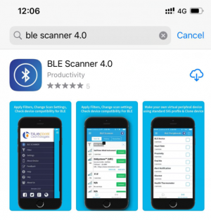
1.For iOS system
Enter APP STORE to search BLE Scanner 4.0, then download it.
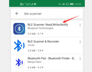
2.For Android system
Enter Google Play to find out BLE Scanner, then download.
And allow APP to access“location”, you could enable “location”in settings of your cellphone.
- 3.After installation, open App and enable “Location and Bluetooth” permission.
- 4.We take iOS version as example. The operation method of Android version is almost same as it.
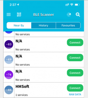
- 5.Scan Bluetooth module to get Bluetooth BLE 4.0. Its name is HMSoft.
Then click“connect”to link with Bluetooth and use it.
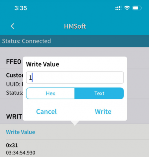
6. After connecting to HMSoft, click it to get multiple options, such as device information, access permission, general and custom service. Choose “CUSTOM SERVICE”
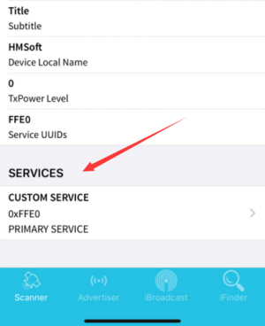
7.Then pop up the following page
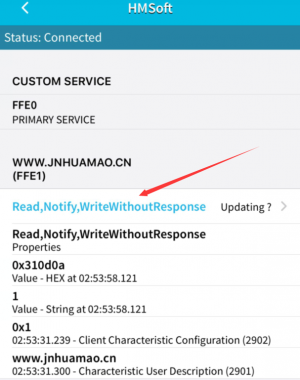
8. Click(Read,Notify,WriteWithoutResponse)to enter the following page
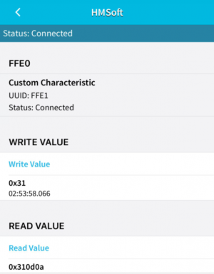
9.Click Write Value, appear the interface to enter HEX or Text.
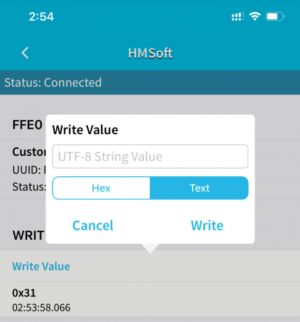
10.Open the serial monitor on Arduino,enter a 0 or other character at Text interface.
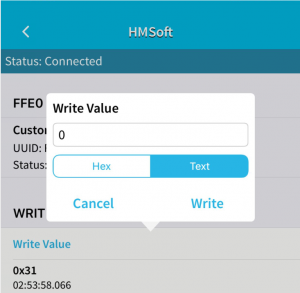
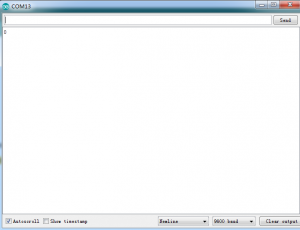
Then click“Write”, open serial monitor to view if there is a “0” signal
(7)Code Explanation
Serial.available() : The current rest characters when return to buffer area. Generally, this function is used to judge if there is data in buffer. When Serial.available()>0, it means that serial receives the data and can be read
Serial.read():Read a data of a Byte in buffer of serial port, for instance, device sends data to Arduino via serial port, then we could read data by “Serial.read()”
(8)Extension Practice
We could send a command via cellphone to turn on and off a LED.
D10 is connected to a LED, as shown below:
/*
 keyestudio Mini Tank Robot v2.0
 lesson 7.2
 Bluetooth
 http://www.keyestudio.com
*/
int ledpin=11;
void setup()
{Serial.begin(9600);
 pinMode(ledpin,OUTPUT);
}
void loop()
{ int i;
  if (Serial.available())
  {i=Serial.read();
    Serial.println("DATA RECEIVED:");
    if(i=='1')
    { digitalWrite(ledpin,1);
      Serial.println("led on");
    }
    if(i=='0')
    { digitalWrite(ledpin,0);
      Serial.println("led off");
}}}//*******************************************
Click “Write” on APP, when you enter 1, LED will be on, when you input 0, LED will be off. (Remember to remove the Bluetooth module after finishing experiment, otherwise, burning code will be affected)
Project 8: Motor Driving and Speed Control
(1) Description
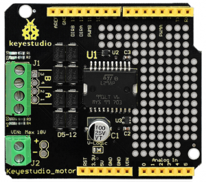
There are many ways to drive the motor. Our tank robot uses the most commonly used L298P solution. L298P is an excellent high-power motor driver IC produced by STMicroelectronics. It can directly drive DC motors, two-phase and four-phase stepping motors. The driving current up to 2A, and output terminal of motor adopts eight high-speed Schottky diodes as protection.
We designed a shield based on the circuit of L298p.
The stacked design reduces the technical difficulty of using and driving the motor.
(2)Specification
Circuit Diagram for L298P Board
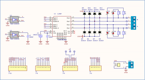
- 1)Logic part input voltage: DC5V
- 2)Driving part input voltage: DC 7-12V
- 3)Logic part working current: <36mA
- 4)Driving part working current: <2A
- 5)Maximum power dissipation: 25W (T=75℃)
- 6)Working temperature: -25℃~+130℃
- 7)Control signal input level: high level 2.3V<Vin<5V, low level -0.3V<Vin<1.5V
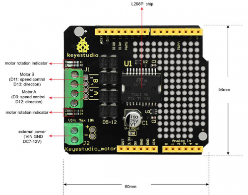
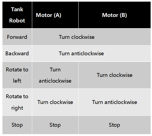
(3)Drive Robot to Move
Through the above circuit diagram, the direction pin of A motor is D12, and speed pin is D3; D13 is the direction pin of B motor, D11 is speed pin.
We know how to control digital ports according to the following chart.
PWM decides 2 motors to turn so as to drive robot car. The PWM value is in the range of 0-255, the larger the number, the faster the motor rotates.
(4)Equipment
(5)Connection Diagram
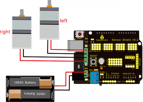
Note: the 4Pin terminal block is marked with silkscreen 1234. The red line of right rear motor is connected to terminal 1, black line is linked with end 2. The red line of left front motor is attached to terminal 3, black line is linked with port 4.
(6)Test Code
/*
 keyestudio Mini Tank Robot v2.0
 lesson 8.1
 motor driver
 http://www.keyestudio.com
*/

#define ML_Ctrl 13  //define the direction control pin of left motor
#define ML_PWM 11   //define the PWM control pin of left motor
#define MR_Ctrl 12  //define direction control pin of right motor
#define MR_PWM 3   // define the PWM control pin of right motor

void setup()
{
  pinMode(ML_Ctrl, OUTPUT);//define direction control pin of left motor as output
  pinMode(ML_PWM, OUTPUT);//define PWM control pin of left motor as output
  pinMode(MR_Ctrl, OUTPUT);//define direction control pin of right motor as output.
  pinMode(MR_PWM, OUTPUT);//define the PWM control pin of right motor as output
}

void loop()
{
  digitalWrite(ML_Ctrl,LOW);//set the direction control pin of left motor to LOW
  analogWrite(ML_PWM,200);//set the PWM control speed of left motor to 200
  digitalWrite(MR_Ctrl,LOW);//set the direction control pin of right motor to LOW
  analogWrite(MR_PWM,200);//set the PWM control speed of right motor to 200

  //front
  delay(2000);//delay in 2s
   digitalWrite(ML_Ctrl,HIGH);//set the direction control pin of left motor to HIGH
  analogWrite(ML_PWM,200);//set the PWM control speed of left motor to 200
digitalWrite(MR_Ctrl,HIGH);//set the direction control pin of right motor to HIGH
  analogWrite(MR_PWM,200);//set the PWM control speed of right motor to 200

   //back
  delay(2000);//delay in 2s
  digitalWrite(ML_Ctrl,HIGH);//set the direction control pin of left motor to HIGH
  analogWrite(ML_PWM,200);//set the PWM control speed of left motor to 200
  digitalWrite(MR_Ctrl,LOW);//set the direction control pin of right motor to LOW
  analogWrite(MR_PWM,200);//set the PWM control speed of right motor to 200

    //left
  delay(2000);//delay in 2s
   digitalWrite(ML_Ctrl,LOW);//set the direction control pin of left motor to LOW
  analogWrite(ML_PWM,200);//set the PWM control speed of left motor to 200
  digitalWrite(MR_Ctrl,HIGH);//set the direction control pin of right motor to HIGH
  analogWrite(MR_PWM,200);//set the PWM control speed of right motor to 200

   //right
  delay(2000);//delay in 2s
  analogWrite(ML_PWM,0);//set the PWM control speed of left motor to 0
  analogWrite(MR_PWM,0);//set the PWM control speed of right motor to 0

    //stop
  delay(2000);//delay in 2s
}//*****************************************
(7)Test Result
Hook up by connection diagram, upload code and power on, smart car goes forward and back for 2s, turns left and right for 2s, stops for 2s and alternately.
(8) Code Explanation
digitalWrite(ML_Ctrl,LOW): the rotation direction of motor is decided by the high/low level and and the pins that decide rotation direction are general pins.
analogWrite(ML_PWM,200): the speed of motor is regulated by PWM, The speed of motor is regulated by PWM, and the pins that decide the speed of motor have to be PWM pins.
(9)Extension Practice
Hook up in same way
/*
 keyestudio Mini Tank Robot v2.0
 lesson 8.2
 motor driver pwm
 http://www.keyestudio.com
*/
#define ML_Ctrl 13  //define the direction control pin of left motor
#define ML_PWM 11   //define the PWM control pin of left motor
#define MR_Ctrl 12  //define the control pin of right motor
#define MR_PWM 3   //define the PWM control pin of right motor
void setup()
{ pinMode(ML_Ctrl, OUTPUT);//define the direction control pin of left motor as OUTPUT
  pinMode(ML_PWM, OUTPUT);//define the PWM control pin of left motor as OUTPUT
  pinMode(MR_Ctrl, OUTPUT);//define the direction control pin of right motor as OUTPUT
  pinMode(MR_PWM, OUTPUT);//define the PWM control pin of right motor as OUTPUT

}
void loop()
{ digitalWrite(ML_Ctrl,LOW);//Set direction control pin of left motor to LOW
  analogWrite(ML_PWM,100);// Set the PWM control speed of left motor to 100
  digitalWrite(MR_Ctrl,LOW);//Set the direction control pin of right motor to LOW
  analogWrite(MR_PWM,100);//Set the PWM control speed of right motor to 100
  //front
  delay(2000);//define 2s
  digitalWrite(ML_Ctrl,HIGH);//Set direction control pin of left motor to HIGH level
  analogWrite(ML_PWM,100);//Set the PWM control speed of left motor to 100
  digitalWrite(MR_Ctrl,HIGH);//Set direction control pin of right motor to HIGH level
  analogWrite(MR_PWM,100);//Set the PWM control speed of right motor to 100
   //back
  delay(2000);//define 2s
  digitalWrite(ML_Ctrl,HIGH);//Set direction control pin of left motor to HIGH level
  analogWrite(ML_PWM,100);//Set the PWM control speed of left motor to 100
  digitalWrite(MR_Ctrl,LOW);//Set direction control pin of right motor to LOW level
  analogWrite(MR_PWM,100);//Set the PWM control speed of right motor to 100
    //left
  delay(2000);//define 2s
   digitalWrite(ML_Ctrl,LOW);//set the direction control pin of left motor to LOW
  analogWrite(ML_PWM,100);//set the PWM control speed of left motor to 200
  digitalWrite(MR_Ctrl,HIGH);//set the direction control pin of right motor to HIGH
  analogWrite(MR_PWM,100);//set the PWM control speed of right motor to 100
   //right
  delay(2000);//define 2s
  analogWrite(ML_PWM,0);//set the PWM control speed of left motor to 0
  analogWrite(MR_PWM,0);// set the PWM control speed of right motor to 0

    //stop
  delay(2000);//define 2s
}//******************************************************************
Upload code successfully, the motors rotate faster.
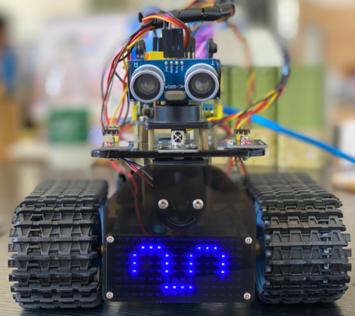
Project 9: LED Expression Panel
(1)Description
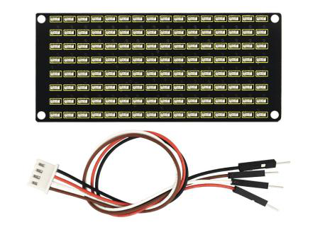
If we add an expression panel to the robot, it will be amazing. Keyestudio’s 8*16 dot matrix can meet your requirements. You can create facial expressions, patterns or other interesting displays yourself. 8*16 LED light board comes with 128 LEDs. The data of the microprocessor (arduino) communicates with the AiP1640 through the two-wire bus interface, so as to control the 128 LEDs on the module, which produce the patterns you need on dot matrix. To facilitate wiring, we also provide a HX-2.54 4Pin wiring.
(2)Specification
- Working voltage: DC 3.3-5V
- Power loss: 400mW
- Oscillation frequency: 450KHz
- Drive current: 200mA
- Working temperature: -40~80℃
- Communication method: two-wire bus
(3)Equipment
(4)8*16 Dot Matrix Display
Circuit Graphic
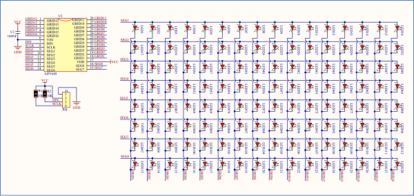
The principle of 8*16 dot matrix:
How to control each led light of 8*16 dot matrix? We know that a byte has 8 bits, each bit is 0 or 1. When a bit is 0, turn off LED and when a bit is 0, turn on LED.
Thereby, one byte can control the LED in a row of dot matrix, so 16 bytes can control 16 columns of led lights, that is, 8*16 dot matrix.
Interface Description and Communication Protocol:
The data of the microprocessor (arduino) communicates with the AiP1640 through the two-wire bus interface.
The communication protocol diagram is shown below:
(SCLK) is SCL, (DIN) is SDA:
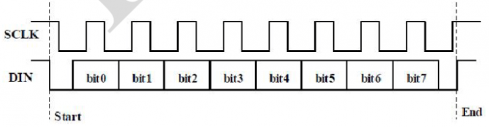
①The starting condition for data input: SCL is high level and SDA changes from high to low.
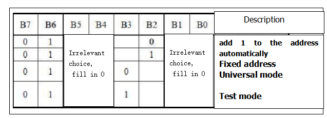
②For data command setting, there are methods as shown in the figure below.
In our sample program, select the way to add 1 to the address automatically, the binary value is 0100 0000 and the corresponding hexadecimal value is 0x40.
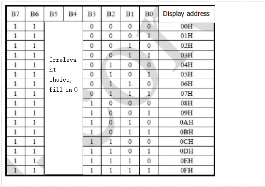
③For address command setting, the address can be selected as shown below.
The first 00H is selected in our sample program, and the binary number 1100 0000 corresponds to the hexadecimal 0xc0
- ④The requirement for data input is that SCL is high level when inputting data, the signal on SDA must remain unchanged. Only when the clock signal on SCL is low level, the signal on SDA can be altered. The data input is low-order first, high-order is behind
- ⑤ The condition to end data transmission is that when SCL is low, SDA is low, and when SCL is high, the SDA level also becomes high.
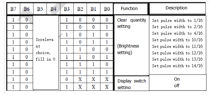
- ⑥ Display control, set different pulse width, the pulse width can be selected as shown below
- In the example, we choose pulse width 4/16, and the hexadecimal corresponds to 1000 1010 is 0x8A
4. Introduction for Modulus Tool
The online version of dot matrix modulus tool:
http://dotmatrixtool.com/#
①Open links to enter the following page.
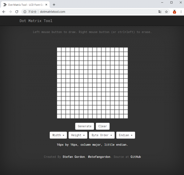
②The dot matrix is 8*16 in this project, so set the height to 8, width to 16, as shown below.
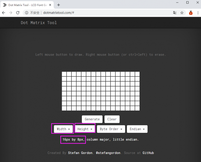
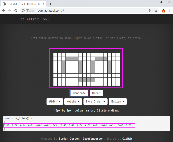
③ Generate hexadecimal data from the pattern
As shown below, press the left mouse button to select, the right button to cancel, draw the pattern you want, click Generate, and the hexadecimal data we need will be produced.
(5)Connection Diagram
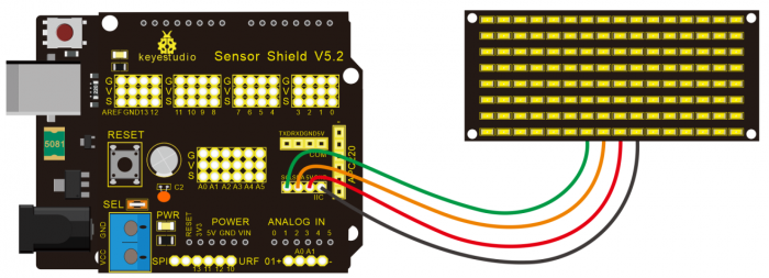
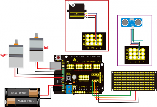
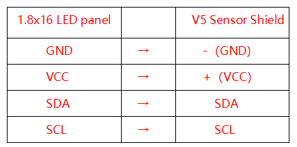
Wiring note: The GND, VCC, SDA, and SCL of the 8×16 LED panel are respectively connected to -(GND), + (VCC), A4 and A5 of the keyestudio sensor expansion board for two-wire serial communication. (Note: This pin is connected to arduino IIC, but this module is not IIC communication, it can be linked with any two pins.)
(6)Test Code
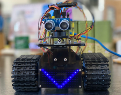
The code that shows smile face
/*
 keyestudio Mini Tank Robot v2.0
 lesson 9.1
 Matrix  face
 http://www.keyestudio.com
*/
//the data of smiley from modulus tool
unsigned char smile[] = {0x00, 0x00, 0x1c, 0x02, 0x02, 0x02, 0x5c, 0x40, 0x40, 0x5c, 0x02, 0x02, 0x02, 0x1c, 0x00, 0x00};

#define SCL_Pin  A5  //Set clock pin to A5
#define SDA_Pin  A4  //Set data pin to A4

void setup(){
  //Set pin to output
  pinMode(SCL_Pin,OUTPUT);
  pinMode(SDA_Pin,OUTPUT);
  //clear the display
  //matrix_display(clear);
}
void loop(){
  matrix_display(smile);  // display smile face
}
// the function for dot matrix display
void matrix_display(unsigned char matrix_value[])
{
  IIC_start();  // use the function of the data transmission start condition
  IIC_send(0xc0);  //select address

  for(int i = 0;i < 16;i++) //pattern data has 16 bits
  {
     IIC_send(matrix_value[i]); //convey the pattern data
  }

  IIC_end();   //end the transmission of pattern data
  IIC_start();
  IIC_send(0x8A);  //display control, set pulse width to 4/16 s
  IIC_end();
}

//the condition to start conveying data
void IIC_start()
{
  digitalWrite(SCL_Pin,HIGH);
  delayMicroseconds(3);
  digitalWrite(SDA_Pin,HIGH);
  delayMicroseconds(3);
  digitalWrite(SDA_Pin,LOW);
  delayMicroseconds(3);
}
//Convey data
void IIC_send(unsigned char send_data)
{
  for(char i = 0;i < 8;i++)  //Each byte has 8 bits 8bit for every character
  {
      digitalWrite(SCL_Pin,LOW);  // pull down clock pin SCL_Pin to change the signal of SDA
      delayMicroseconds(3);
      if(send_data & 0x01)  //set high and low level of SDA_Pin according to 1 or 0 of every bit
      {
        digitalWrite(SDA_Pin,HIGH);
      }
      else
      {
        digitalWrite(SDA_Pin,LOW);
      }
      delayMicroseconds(3);
      digitalWrite(SCL_Pin,HIGH); //pull up the clock pin SCL_Pin to stop transmission
      delayMicroseconds(3);
      send_data = send_data >> 1;  // detect bit by bit, shift the data to the right by one
  }
}

//The sign of ending data transmission
void IIC_end()
{
  digitalWrite(SCL_Pin,LOW);
  delayMicroseconds(3);
  digitalWrite(SDA_Pin,LOW);
  delayMicroseconds(3);
  digitalWrite(SCL_Pin,HIGH);
  delayMicroseconds(3);
  digitalWrite(SDA_Pin,HIGH);
  delayMicroseconds(3);
}
//******************************************************
(7)Test Result
Wire according to connection diagram. The DIP switch is dialed to right end and power on, the smile face appears on dot matrix.
(8)Extension Practice
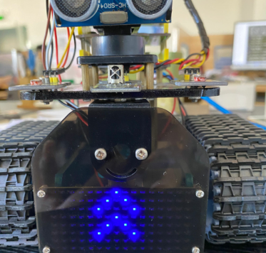
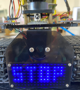
We use the modulo tool (http://dotmatrixtool.com/#)to make the dot matrix alternately display start, go front and stop patterns then clear the patterns, the time interval is 2000 milliseconds.
Get the graphical code to be displayed via modulus tool
- Start:
- 0x01,0x02,0x04,0x08,0x10,0x20,0x40,0x80,0x80,0x40,0x20,0x10,0x08,0x04,0x02,0x01
- Go front:
- 0x00,0x00,0x00,0x00,0x00,0x24,0x12,0x09,0x12,0x24,0x00,0x00,0x00,0x00,0x00,0x00
- Go back:
- 0x00,0x00,0x00,0x00,0x00,0x24,0x48,0x90,0x48,0x24,0x00,0x00,0x00,0x00,0x00,0x00
- Turn left:
- 0x00,0x00,0x00,0x00,0x00,0x00,0x44,0x28,0x10,0x44,0x28,0x10,0x44,0x28,0x10,0x00
- Turn left:
- 0x00,0x10,0x28,0x44,0x10,0x28,0x44,0x10,0x28,0x44,0x00,0x00,0x00,0x00,0x00,0x00
- Stop:
- 0x2E,0x2A,0x3A,0x00,0x02,0x3E,0x02,0x00,0x3E,0x22,0x3E,0x00,0x3E,0x0A,0x0E,0x00
- Clear the displayed code:0x00,0x00,0x00,0x00,0x00,0x00,0x00,0x00,0x00,0x00,0x00,0x00,0x00,0x00,0x00,0x00
The code that the multiple patterns shift:
/* keyestudio Mini Tank Robot v2.0
 lesson 9.2
 Matrix loop
 http://www.keyestudio.com
*/
//Array, used to store the data of the pattern, can be calculated by yourself or obtained from the modulus tool
unsigned char start01[] =
{0x01,0x02,0x04,0x08,0x10,0x20,0x40,0x80,0x80,0x40,0x20,0x10,0x08,0x04,0x02,0x01};
unsigned char front[] =
{0x00,0x00,0x00,0x00,0x00,0x24,0x12,0x09,0x12,0x24,0x00,0x00,0x00,0x00,0x00,0x00};
unsigned char back[] =
{0x00,0x00,0x00,0x00,0x00,0x24,0x48,0x90,0x48,0x24,0x00,0x00,0x00,0x00,0x00,0x00};
unsigned char left[] =
{0x00,0x00,0x00,0x00,0x00,0x00,0x44,0x28,0x10,0x44,0x28,0x10,0x44,0x28,0x10,0x00};
unsigned char right[] =
{0x00,0x10,0x28,0x44,0x10,0x28,0x44,0x10,0x28,0x44,0x00,0x00,0x00,0x00,0x00,0x00};
unsigned char STOP01[] =
{0x2E,0x2A,0x3A,0x00,0x02,0x3E,0x02,0x00,0x3E,0x22,0x3E,0x00,0x3E,0x0A,0x0E,0x00};
unsigned char clear[] =
{0x00,0x00,0x00,0x00,0x00,0x00,0x00,0x00,0x00,0x00,0x00,0x00,0x00,0x00,0x00,0x00};
#define SCL_Pin  A5  //Set clock pin to A5
#define SDA_Pin  A4  //Set data pin to A4
void setup(){
  //Set pins to output
  pinMode(SCL_Pin,OUTPUT);
  pinMode(SDA_Pin,OUTPUT);
  //Clear the display
  matrix_display(clear);
}
void loop(){
  matrix_display(start01);  // Display start pattern
  delay(2000);
  matrix_display(front);    //Front pattern
  delay(2000);
  matrix_display(STOP01);   //Stop pattern
  delay(2000);
  matrix_display(clear);    //Clear the display Clear the screen
  delay(2000);
}
// This function is used to display of dot matrix
void matrix_display(unsigned char matrix_value[])
{
  IIC_start();  //call the function that data transmission start
  IIC_send(0xc0);  //Choose address

  for(int i = 0;i < 16;i++) //pattern data has 16 bits
  {
     IIC_send(matrix_value[i]); //data to convey patterns
  }
  IIC_end();   //end the transmission of pattern dataEnd
  IIC_start();
  IIC_send(0x8A);  //display control, set pulse width to 4/16
  IIC_end();
}
//The condition starting to transmit data
void IIC_start()
{
  digitalWrite(SCL_Pin,HIGH);
  delayMicroseconds(3);
  digitalWrite(SDA_Pin,HIGH);
  delayMicroseconds(3);
  digitalWrite(SDA_Pin,LOW);
  delayMicroseconds(3);
}
//Convey data
void IIC_send(unsigned char send_data)
{
  for(char i = 0;i < 8;i++)  //Each byte has 8 bits
  {
      digitalWrite(SCL_Pin,LOW);  //pull down clock pin SCL Pin to change the signals of SDA
delayMicroseconds(3);
      if(send_data & 0x01)  //set high and low level of SDA_Pin according to 1 or 0 of every bit
      {
        digitalWrite(SDA_Pin,HIGH);
      }
      else
      {
        digitalWrite(SDA_Pin,LOW);
      }
      delayMicroseconds(3);
      digitalWrite(SCL_Pin,HIGH); //pull up clock pin SCL_Pin to stop transmitting data
      delayMicroseconds(3);
      send_data = send_data >> 1;  //detect bit by bit, so shift the data right by one
  }}
//The sign that data transmission ends
void IIC_end()
{
  digitalWrite(SCL_Pin,LOW);
  delayMicroseconds(3);
  digitalWrite(SDA_Pin,LOW);
  delayMicroseconds(3);
  digitalWrite(SCL_Pin,HIGH);
  delayMicroseconds(3);
  digitalWrite(SDA_Pin,HIGH);
  delayMicroseconds(3);}
//*****************************************************
Upload code on development board, 8*16 dot matrix display go front and back and stop patterns, alternately.
Project 10: Light Follow Robot
(1)Description
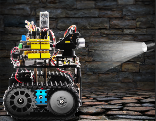
We’ve introduce how to use various sensors, modules.
In this lesson, we combine with hardware knowledge — photoresistor module, motor driving, to build a light-following robot!
Just need to use 2 photoresistor modules to detect the light intensity at the both side of robot. Read the analog value to rotate the 2 motors, thus drive the tank robot run.
The specific logic of light following robot is shown as the table below:
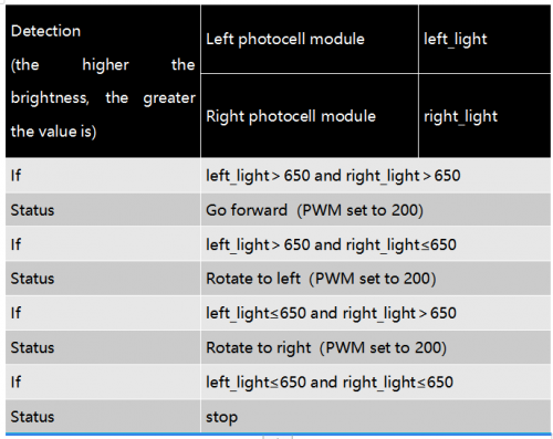
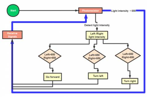
We make a flow chart based on the above logic table, as shown below:
(2)Connection Diagram
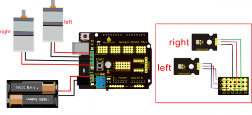
Hook-up Attention:
The 4Pin terminal block is marked with silkscreen 1234. The red line of right rear motor is connected to terminal 1, black line is linked with end 2. The red line of left front motor is attached to terminal 3, black line is linked with port 4.
(3)Test Code
/*
 keyestudio Mini Tank Robot v2.0
 lesson 10
 Light-following tank
 http://www.keyestudio.com
*/
#define light_L_Pin A1   //define the pin of left photo resistor
#define light_R_Pin A2   //define the pin of right photo resistor
#define ML_Ctrl 13  //define the direction control pin of left motor
#define ML_PWM 11   //define the PWM control pin of left motor
#define MR_Ctrl 12  //define the direction control pin of right motor
#define MR_PWM 3   //define the PWM control pin of right motor
int left_light;
int right_light;
void setup(){
  Serial.begin(9600);
  pinMode(light_L_Pin, INPUT);
  pinMode(light_R_Pin, INPUT);
  pinMode(ML_Ctrl, OUTPUT);
  pinMode(ML_PWM, OUTPUT);
  pinMode(MR_Ctrl, OUTPUT);
  pinMode(MR_PWM, OUTPUT);
}
void loop(){
  left_light = analogRead(light_L_Pin);
  right_light = analogRead(light_R_Pin);
  Serial.print("left_light_value = ");
  Serial.println(left_light);
  Serial.print("right_light_value = ");
  Serial.println(right_light);
  if (left_light > 650 && right_light > 650) //the value detected photo resistor,go front
  {
    Car_front();
  }
  else if (left_light > 650 && right_light <= 650)  //the value detected photo resistor,turn left
  {
    Car_left();
  }
  else if (left_light <= 650 && right_light > 650) //the value detected photo resistor,turn right
  {
    Car_right();
  }
  else  //other situations, stop
  {
    Car_Stop();
  }
}
void Car_front()
{
  digitalWrite(MR_Ctrl,LOW);
  analogWrite(MR_PWM,200);
  digitalWrite(ML_Ctrl,LOW);
  analogWrite(ML_PWM,200);
}
void Car_left()
{
  digitalWrite(MR_Ctrl,LOW);
  analogWrite(MR_PWM,200);
  digitalWrite(ML_Ctrl,HIGH);
  analogWrite(ML_PWM,200);
}
void Car_right()
{
  digitalWrite(MR_Ctrl,HIGH);
  analogWrite(MR_PWM,200);
  digitalWrite(ML_Ctrl,LOW);
  analogWrite(ML_PWM,200);
}
void Car_Stop()
{
  digitalWrite(MR_Ctrl,LOW);
  analogWrite(MR_PWM,0);
  digitalWrite(ML_Ctrl,LOW);
  analogWrite(ML_PWM,0);
}
//****************************************************************
(4)Test Result
Upload code on keyestudio V4.0 development board, DIP switch is dialed to right end and power on, the smart robot follows light to move.
Project 11: Ultrasonic Avoid Tank
(1)Description
In this program, the ultrasonic sensor detects the distance of obstacle to send signals that control the robot car. Next, let’s show you how to make an obstacle avoidance car.
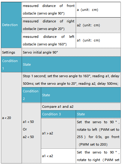
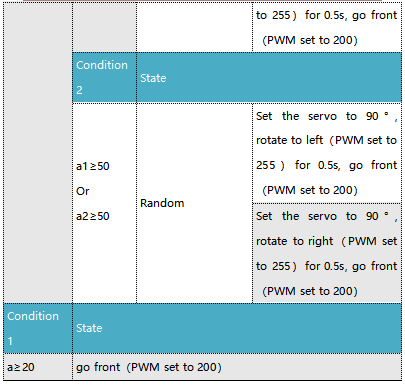
The specific logic of ultrasonic avoiding robot is as shown below:
(2)Flow chart
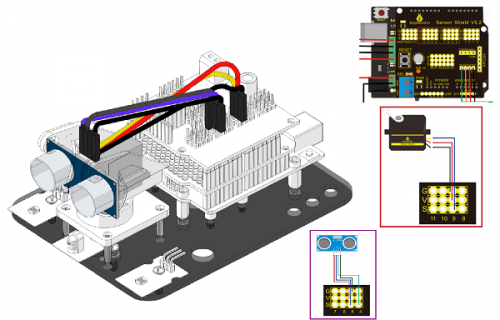
(3)Connection Diagram:
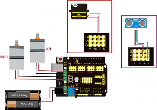
Note: “-”、“+” and “S” pins of servo are respectively attached to G(GND), V(VCC)and D9 of expansion board. The VCC, Trig, Echo and Gnd of ultrasonic sensor are linked with 5v(V), 5(S), Echo and Gnd(G) of expansion board.
(4)Test Code:
/*
 keyestudio Mini Tank Robot v2.0
 lesson 11
 ultrasonic_avoid_tank
 http://www.keyestudio.com
*/
int random2;
int a;
int a1;
int a2;
#define ML_Ctrl 13  //define the direction control pin of left motor
#define ML_PWM 11   //define PWM control pin of left motor
#define MR_Ctrl 12  //define the direction control pin of right motor
#define MR_PWM 3   //define PWM control pin of right motor

#define Trig 5  //ultrasonic trig Pin
#define Echo 4  //ultrasonic echo Pin
int distance;
#define servoPin 9  //servo Pin
int pulsewidth;
/************the function to run motor**************/
void Car_front()
{
  digitalWrite(MR_Ctrl,LOW);
  analogWrite(MR_PWM,200);
  digitalWrite(ML_Ctrl,LOW);
  analogWrite(ML_PWM,200);
}
void Car_back()
{
  digitalWrite(MR_Ctrl,HIGH);
  analogWrite(MR_PWM,200);
  digitalWrite(ML_Ctrl,HIGH);
  analogWrite(ML_PWM,200);
}
void Car_left()
{
  digitalWrite(MR_Ctrl,LOW);
  analogWrite(MR_PWM,255);
  digitalWrite(ML_Ctrl,HIGH);
  analogWrite(ML_PWM,255);
}
void Car_right()
{
  digitalWrite(MR_Ctrl,HIGH);
  analogWrite(MR_PWM,255);
  digitalWrite(ML_Ctrl,LOW);
  analogWrite(ML_PWM,255);
}
void Car_Stop()
{
  digitalWrite(MR_Ctrl,LOW);
  analogWrite(MR_PWM,0);
  digitalWrite(ML_Ctrl,LOW);
  analogWrite(ML_PWM,0);
}

//The function to control servo
void procedure(int myangle) {
  for (int i = 0; i <= 50; i = i + (1)) {
    pulsewidth = myangle * 11 + 500;
    digitalWrite(servoPin,HIGH);
    delayMicroseconds(pulsewidth);
    digitalWrite(servoPin,LOW);
    delay((20 - pulsewidth / 1000));
  }
}
//The function to control ultrasonic sensor
float checkdistance() {
  digitalWrite(Trig, LOW);
  delayMicroseconds(2);
  digitalWrite(Trig, HIGH);
  delayMicroseconds(10);
  digitalWrite(Trig, LOW);
  float distance = pulseIn(Echo, HIGH) / 58.00;  //58.20, that is, 2*29.1=58.2
  delay(10);
  return distance;
}
  //****************************************************************
void setup(){
  pinMode(servoPin, OUTPUT);
  procedure(90); //set servo to 90°

  pinMode(Trig, OUTPUT);
  pinMode(Echo, INPUT);
  pinMode(ML_Ctrl, OUTPUT);
  pinMode(ML_PWM, OUTPUT);
  pinMode(MR_Ctrl, OUTPUT);
  pinMode(MR_PWM, OUTPUT);
}
void loop(){
  random2 = random(1, 100);
  a = checkdistance();  //assign the front distance detected by ultrasonic sensor to variable a

  if (a < 20) //when the front distance detected is less than 20
  {
      Car_Stop();  //robot stops
      delay(500); //delay in 500ms
      procedure(160);  //Ultrasonic platform turns left
      for (int j = 1; j <= 10; j = j + (1)) { //for statement, the data will be more accurate if ultrasonic sensor detect a few times.
        a1 = checkdistance();  //assign the left distance detected by ultrasonic sensor to variable a1
      }
      delay(300);
      procedure(20); //Ultrasonic platform turns right
      for (int k = 1; k <= 10; k = k + (1)) {
        a2 = checkdistance(); //assign the right distance detected by ultrasonic sensor to variable a2
      }

      if (a1 < 50 || a2 < 50)  //robot will turn to the longer distance side when left or right distance is less than 50cm.
      {
        if (a1 > a2) //left distance is greater than right side
        {
          procedure(90);  //Ultrasonic platform turns back to right ahead
Car_left();  //robot turns left
          delay(500);  //turn left for 500ms
          Car_front(); //go front
        }
        else
        {
          procedure(90);
          Car_right(); //robot turns right
          delay(500);
          Car_front();  //go front
        }
      }
      else  //If both side is greater than or equal to 50cm, turn left or right randomly
      {
        if ((long) (random2) % (long) (2) == 0)  //When the random number is even
        {
          procedure(90);
          Car_left(); //tank robot turns left
          delay(500);
          Car_front(); //go front
        }
        else
        {
          procedure(90);
          Car_right(); //robot turns right
          delay(500);
          Car_front(); //go front
       }
     }
  }
  else  //If the front distance is greater than or equal to 20cm, robot car will go front
  {
      Car_front(); //go front
  }
}
  //****************************************************************
(5)Test Result
Upload code successfully, DIP switch is dialed to right end and power on, tank robot goes forward. It can automatically avoid barrier.
Project 12: Ultrasonic Follow Tank
(1)Description
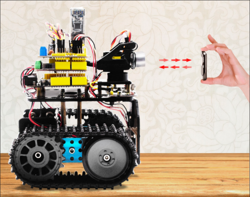
In project 11, we made an obstacle avoidance car. In fact, we only need to alter a test code to transform an obstacle avoidance car into following car. In this lesson, we will make an ultrasonic follow robot. The ultrasonic sensor detects the distance between smart car and the obstacle to drive tank car to move.
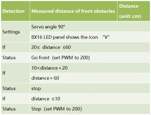
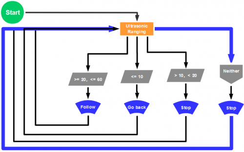
The specific logic of ultrasonic follow robot is as shown below:
(2)Flow chart
(3)Connection Diagram
Wire-up note:
(4)Test Code
 /*
 keyestudio Mini Tank Robot v2.0
 lesson 12
 ultrasonic follow tank
 http://www.keyestudio.com
*/
//Array, used to store the data of the pattern, can be calculated by yourself or obtained from the modulus tool
unsigned char start01[] = {0x01,0x02,0x04,0x08,0x10,0x20,0x40,0x80,0x80,0x40,0x20,0x10,0x08,0x04,0x02,0x01};
unsigned char front[] = {0x00,0x00,0x00,0x00,0x00,0x24,0x12,0x09,0x12,0x24,0x00,0x00,0x00,0x00,0x00,0x00};
unsigned char back[] = {0x00,0x00,0x00,0x00,0x00,0x24,0x48,0x90,0x48,0x24,0x00,0x00,0x00,0x00,0x00,0x00};
unsigned char left[] = {0x00,0x00,0x00,0x00,0x00,0x00,0x44,0x28,0x10,0x44,0x28,0x10,0x44,0x28,0x10,0x00};
unsigned char right[] = {0x00,0x10,0x28,0x44,0x10,0x28,0x44,0x10,0x28,0x44,0x00,0x00,0x00,0x00,0x00,0x00};
unsigned char STOP01[] = {0x2E,0x2A,0x3A,0x00,0x02,0x3E,0x02,0x00,0x3E,0x22,0x3E,0x00,0x3E,0x0A,0x0E,0x00};
unsigned char clear[] = {0x00,0x00,0x00,0x00,0x00,0x00,0x00,0x00,0x00,0x00,0x00,0x00,0x00,0x00,0x00,0x00};
#define SCL_Pin  A5  //Set clock pin to A5
#define SDA_Pin  A4  //Set data pin to A4

#define ML_Ctrl 13  //define the direction control pin of left motor
#define ML_PWM 11   //define PWM control pin of left motor
#define MR_Ctrl 12  //define the direction control pin of right motor
#define MR_PWM 3   //define PWM control pin of right motor
#define Trig 5  //ultrasonic trig Pin
#define Echo 4  //ultrasonic echo Pin
int distance;
int pulsewidth;
#define servoPin 9  //servo Pin
void setup(){
  Serial.begin(9600);
  pinMode(SCL_Pin,OUTPUT);
  pinMode(SDA_Pin,OUTPUT);
  matrix_display(clear); //Clear the display
  matrix_display(start01);  //display start pattern
  pinMode(servoPin, OUTPUT);
  procedure(90); //set servo to 90°
  pinMode(Trig, OUTPUT);
  pinMode(Echo, INPUT);
  pinMode(ML_Ctrl, OUTPUT);
  pinMode(ML_PWM, OUTPUT);
  pinMode(MR_Ctrl, OUTPUT);
  pinMode(MR_PWM, OUTPUT);
}
void loop(){
  distance = checkdistance();  //assign the distance detected by ultrasonic sensor to distance
  if (distance >= 20 && distance <= 60) //range to go front
  {
    Car_front();
  }
  else if (distance > 10 && distance < 20)  //range to stop
  {
    Car_Stop();
  }
  else if (distance <= 10)  //range to go back
  {
    Car_back();
  }
  else  //other situations, stop
  {
    Car_Stop();
  }
}
/***********the function for motor running****************/
void Car_front()
{
  digitalWrite(MR_Ctrl,LOW);
  analogWrite(MR_PWM,200);
  digitalWrite(ML_Ctrl,LOW);
  analogWrite(ML_PWM,200);
}
void Car_back()
{
  digitalWrite(MR_Ctrl,HIGH);
  analogWrite(MR_PWM,200);
  digitalWrite(ML_Ctrl,HIGH);
  analogWrite(ML_PWM,200);
}
void Car_left()
{
  digitalWrite(MR_Ctrl,LOW);
  analogWrite(MR_PWM,200);
  digitalWrite(ML_Ctrl,HIGH);
  analogWrite(ML_PWM,200);
}
void Car_right()
{
  digitalWrite(MR_Ctrl,HIGH);
  analogWrite(MR_PWM,200);
  digitalWrite(ML_Ctrl,LOW);
  analogWrite(ML_PWM,200);
}
void Car_Stop()
{
  digitalWrite(MR_Ctrl,LOW);
  analogWrite(MR_PWM,0);
  digitalWrite(ML_Ctrl,LOW);
  analogWrite(ML_PWM,0);
}

/******************dot matrix********************/
// the function for dot matrix display
void matrix_display(unsigned char matrix_value[])
{
  IIC_start(); // call the function that data transmission start
  IIC_send(0xc0);  //Choose address

  for(int i = 0;i < 16;i++) //pattern data has 16 bits
  {
     IIC_send(matrix_value[i]); //data to convey patterns
  }

  IIC_end();   //end to convey data pattern

  IIC_start();
  IIC_send(0x8A);  //select pulse width4/16, control display
  IIC_end();
}

//The condition starting to transmit data
void IIC_start()
{
  digitalWrite(SCL_Pin,HIGH);
  delayMicroseconds(3);
  digitalWrite(SDA_Pin,HIGH);
  delayMicroseconds(3);
  digitalWrite(SDA_Pin,LOW);
  delayMicroseconds(3);
}

// transmit data
void IIC_send(unsigned char send_data)
{
  for(char i = 0;i < 8;i++)  //Each byte has 8 bits
  {
      digitalWrite(SCL_Pin,LOW);  //pull down clock pin SCL Pin to change the signals of SDA
delayMicroseconds(3);
      if(send_data & 0x01)  //set high and low level of SDA_Pin according to 1 or 0 of every bit
      {
        digitalWrite(SDA_Pin,HIGH);
      }
      else
      {
        digitalWrite(SDA_Pin,LOW);
      }
      delayMicroseconds(3);
      digitalWrite(SCL_Pin,HIGH); //pull up clock pin SCL_Pin to stop transmitting data
      delayMicroseconds(3);
      send_data = send_data >> 1;  // detect bit by bit, so move the data right by one
  }
}
//The sign that data transmission ends
void IIC_end()
{
  digitalWrite(SCL_Pin,LOW);
  delayMicroseconds(3);
  digitalWrite(SDA_Pin,LOW);
  delayMicroseconds(3);
  digitalWrite(SCL_Pin,HIGH);
  delayMicroseconds(3);
  digitalWrite(SDA_Pin,HIGH);
  delayMicroseconds(3);
}
/***************end dot matrix display******************/
//The function to control servo
void procedure(int myangle) {
  for (int i = 0; i <= 50; i = i + (1)) {
    pulsewidth = myangle * 11 + 500;
    digitalWrite(servoPin,HIGH);
    delayMicroseconds(pulsewidth);
    digitalWrite(servoPin,LOW);
    delay((20 - pulsewidth / 1000));
  }}
//The function to control ultrasonic sensor function controlling ultrasonic
float checkdistance() {
  digitalWrite(Trig, LOW);
  delayMicroseconds(2);
  digitalWrite(Trig, HIGH);
  delayMicroseconds(10);
  digitalWrite(Trig, LOW);
  float distance = pulseIn(Echo, HIGH) / 58.20;  //58.20, that is , 2*29.1=58.2
  delay(10);
  return distance;
}
//****************************************************************
(5)Test Result
Upload code successfully, DIP switch is dialed to right end, the servo rotates to 90°, “V” is shown on 8X16 LED panel and smart car moves as the obstacle moves.
Project 13: IR Remote Robot Tank
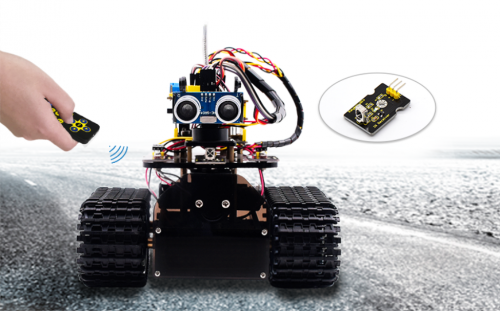
(1)Description
IR remote control is one of most ubiquitous control, applied in TV, electric fan and some household appliances. In this project, we will make an IR remote smart car. And we’ve known every key value on IR remote control. Thus, we could control smart car via and display the patterns on dot matrix via corresponding key value
The specific logic of infrared remote control robot is shown below:
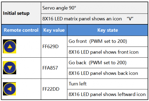
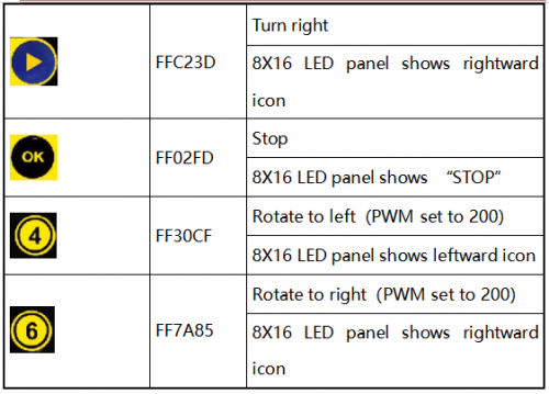
(2)Flow Chart
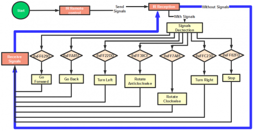
(3)Connection Diagram
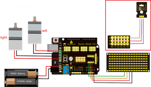
Attention:GND,VCC, SDA, SCL of 8×16 LED panel are respectively linked with -(GND), +(VCC), SDA ,SCL. And “-”、“+” and S of IR receiver module are attached to G(GND), V(VCC) and A0 on sensor shield. On the condition of insufficient digital ports, the analog ports can be treat as digital ports. A0 equals to digital 14, A1 is like digital 15.
(4)Test Code
/*
 keyestudio Mini Tank Robot v2.0
 lesson 13
 IR remote tank
 http://www.keyestudio.com
*/

#include <IRremoteTank.h>
IRrecv irrecv(A0);  //set IRrecv irrecv to A0
decode_results results;
long ir_rec;  //save the IR value received

//Array, used to store the data of the pattern, can be calculated by yourself or obtained from the modulus tool
unsigned char start01[] = {0x01,0x02,0x04,0x08,0x10,0x20,0x40,0x80,0x80,0x40,0x20,0x10,0x08,0x04,0x02,0x01};
unsigned char front[] = {0x00,0x00,0x00,0x00,0x00,0x24,0x12,0x09,0x12,0x24,0x00,0x00,0x00,0x00,0x00,0x00};
unsigned char back[] = {0x00,0x00,0x00,0x00,0x00,0x24,0x48,0x90,0x48,0x24,0x00,0x00,0x00,0x00,0x00,0x00};
unsigned char left[] = {0x00,0x00,0x00,0x00,0x00,0x00,0x44,0x28,0x10,0x44,0x28,0x10,0x44,0x28,0x10,0x00};
unsigned char right[] = {0x00,0x10,0x28,0x44,0x10,0x28,0x44,0x10,0x28,0x44,0x00,0x00,0x00,0x00,0x00,0x00};
unsigned char STOP01[] = {0x2E,0x2A,0x3A,0x00,0x02,0x3E,0x02,0x00,0x3E,0x22,0x3E,0x00,0x3E,0x0A,0x0E,0x00};
unsigned char clear[] = {0x00,0x00,0x00,0x00,0x00,0x00,0x00,0x00,0x00,0x00,0x00,0x00,0x00,0x00,0x00,0x00};
#define SCL_Pin  A5  //Set clock pin to A5
#define SDA_Pin  A4  //Set data pin to A4

#define ML_Ctrl 13  //define the direction control pin of left motor
#define ML_PWM 11   //define PWM control pin of left motor
#define MR_Ctrl 12  //define the direction control pin of right motor
#define MR_PWM 3    //define PWM control pin of right motor

#define servoPin 9 //pin of servo
int pulsewidth; //save the pulse width value of servo

void setup(){
  Serial.begin(9600);
  irrecv.enableIRIn();  //Initialize the IR reception library

  pinMode(ML_Ctrl, OUTPUT);
  pinMode(ML_PWM, OUTPUT);
  pinMode(MR_Ctrl, OUTPUT);
  pinMode(MR_PWM, OUTPUT);

  pinMode(SCL_Pin,OUTPUT);
  pinMode(SDA_Pin,OUTPUT);
  matrix_display(clear); //Clear Screen
  matrix_display(start01);  //show start picture

  pinMode(servoPin, OUTPUT);
  procedure(90);  //Servo rotates to 90°
}

void loop(){
  if (irrecv.decode(&results)) //receive the IR remote value
  {
    ir_rec=results.value;
    String type="UNKNOWN";
    String typelist[14]={"UNKNOWN", "NEC", "SONY", "RC5", "RC6", "DISH", "SHARP", "PANASONIC", "JVC", "SANYO", "MITSUBISHI", "SAMSUNG", "LG", "WHYNTER"};
    if(results.decode_type>=1&&results.decode_type<=13){
      type=typelist[results.decode_type];
    }
    Serial.print("IR TYPE:"+type+"  ");
    Serial.println(ir_rec,HEX);
    irrecv.resume();
  }

  if (ir_rec == 0xFF629D) //Go forward
  {
    Car_front();
    matrix_display(front);  //Display front image
  }
  if (ir_rec == 0xFFA857)  //Robot car goes back
  {
    Car_back();
    matrix_display(front);  //Go back
  }
  if (ir_rec == 0xFF22DD)   //Robot car turns left
  {
    Car_T_left();
    matrix_display(left);  //Display left-turning image
  }
  if (ir_rec == 0xFFC23D)   //Robot car turns right
  {
    Car_T_right();
    matrix_display(right);  //Display right-turning image
  }
  if (ir_rec == 0xFF02FD)   //Robot car stops
  {
    Car_Stop();
    matrix_display(STOP01);  //show stop image
  }
  if (ir_rec == 0xFF30CF)   //robot car rotates anticlockwise
  {
    Car_left();
    matrix_display(left);  //show anticlockwise rotation picture
  }
  if (ir_rec == 0xFF7A85)  //robot car rotates clockwise
  {
    Car_right();
    matrix_display(right);  //show clockwise rotation picture
 }
}
/******************Control Servo*******************/
void procedure(int myangle) {
  for (int i = 0; i <= 50; i = i + (1)) {
    pulsewidth = myangle * 11 + 500;
    digitalWrite(servoPin,HIGH);
    delayMicroseconds(pulsewidth);
    digitalWrite(servoPin,LOW);
    delay((20 - pulsewidth / 1000));
  }
}

/******************Dot Matrix****************/
// this function is used for dot matrix display
void matrix_display(unsigned char matrix_value[])
{
  IIC_start();
  IIC_send(0xc0);  //Choose address
   for(int i = 0;i < 16;i++) //The picture has 16 bits
  {
     IIC_send(matrix_value[i]); //data to convey patterns
  }
  IIC_end();   //end to convey data pattern

  IIC_start();
  IIC_send(0x8A);  //display control, set pulse width to 4/16
  IIC_end();
}

//The condition starting to transmit data
void IIC_start()
{
  digitalWrite(SCL_Pin,HIGH);
  delayMicroseconds(3);
  digitalWrite(SDA_Pin,HIGH);
  delayMicroseconds(3);
  digitalWrite(SDA_Pin,LOW);
  delayMicroseconds(3);
}
//传输数据
void IIC_send(unsigned char send_data)
{
  for(char i = 0;i < 8;i++)  //Each byte has 8 bits 8bits for every character
  {
      digitalWrite(SCL_Pin,LOW);  //pull down clock pin SCL Pin to change the signals of SDA
      delayMicroseconds(3);
      if(send_data & 0x01)  //set high and low level of SDA_Pin according to 1 or 0 of every bit
      {
        digitalWrite(SDA_Pin,HIGH);
      }
      else
      {
        digitalWrite(SDA_Pin,LOW);
      }
      delayMicroseconds(3);
      digitalWrite(SCL_Pin,HIGH); //pull up clock pin SCL_Pin to stop transmitting data
      delayMicroseconds(3);
      send_data = send_data >> 1;  // detect bit by bit, so move the data right by one
  }
}
//The sign that data transmission ends
void IIC_end()
{
  digitalWrite(SCL_Pin,LOW);
  delayMicroseconds(3);
  digitalWrite(SDA_Pin,LOW);
  delayMicroseconds(3);
  digitalWrite(SCL_Pin,HIGH);
  delayMicroseconds(3);
  digitalWrite(SDA_Pin,HIGH);
  delayMicroseconds(3);
}
/***************the function to run motor***************/
void Car_front()
{
  digitalWrite(MR_Ctrl,LOW);
  analogWrite(MR_PWM,200);
  digitalWrite(ML_Ctrl,LOW);
  analogWrite(ML_PWM,200);
}
void Car_back()
{
  digitalWrite(MR_Ctrl,HIGH);
  analogWrite(MR_PWM,200);
  digitalWrite(ML_Ctrl,HIGH);
  analogWrite(ML_PWM,200);
}
void Car_left()
{
  digitalWrite(MR_Ctrl,LOW);
  analogWrite(MR_PWM,255);
  digitalWrite(ML_Ctrl,HIGH);
  analogWrite(ML_PWM,255);
}
void Car_right()
{
  digitalWrite(MR_Ctrl,HIGH);
  analogWrite(MR_PWM,255);
  digitalWrite(ML_Ctrl,LOW);
  analogWrite(ML_PWM,255);
}
void Car_Stop()
{
  digitalWrite(MR_Ctrl,LOW);
  analogWrite(MR_PWM,0);
  digitalWrite(ML_Ctrl,LOW);
  analogWrite(ML_PWM,0);
}
void Car_T_left()
{
  digitalWrite(MR_Ctrl,LOW);
  analogWrite(MR_PWM,255);
  digitalWrite(ML_Ctrl,LOW);
  analogWrite(ML_PWM,180);
}
void Car_T_right()
{
  digitalWrite(MR_Ctrl,LOW);
  analogWrite(MR_PWM,180);
  digitalWrite(ML_Ctrl,LOW);
  analogWrite(ML_PWM,255);
}
 //****************************************************************
(5)Test Result
Upload code successfully and power on, the smart robot can be controlled by IR remote, at same time, the corresponding pattern is shown on 8X16 LED panel.
Project 14: Bluetooth Control Robot
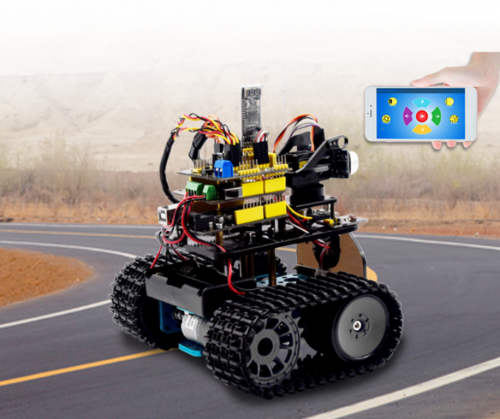
(1)Description
We’ve learned the basic knowledge of Bluetooth, in this lesson, we will make a Bluetooth remote smart car. In the experiment, we default the HM-10 Bluetooth module as a Slave and the cellphone as a Host.
keyes BT car is an APP rolled out by keyestudio team. You could control the robot car by it readily.
There is a guide to how to download and install APP in the document as for your reference. The interface is shown below.
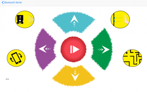
(2)Test Code
/*
 keyestudio Mini Tank Robot v2.0
 lesson 14.1
 bluetooth test
 http://www.keyestudio.com
*/
char ble_val; //character variables, used to save the value of Bluetooth reception
void setup() {
  Serial.begin(9600);
}
void loop() {
  if(Serial.available() > 0)  //judge if there is data in buffer area
  { ble_val = Serial.read();  //read the data from serial buffer
    Serial.println(ble_val);  //print out
  }}
Pull off the Bluetooth module, upload test code, reconnect Bluetooth module, open serial monitor and set baud rate to 9600. Point at Bluetooth module and press keys on APP, the corresponding character is shown below.
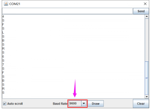
The detected character and corresponding function:
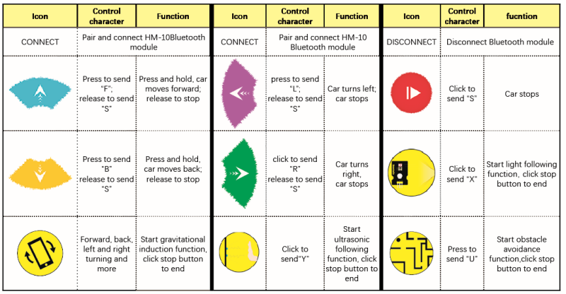
In compliance with the above table, we make a flow chart to assist you to understand well. The flow chart is below:
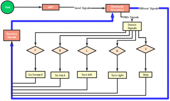
(3)Connection Diagram
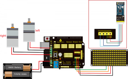
Wiring Attention:
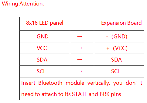
(4)Test Code
Note: Remove the Bluetooth module before uploading test code, otherwise, you will fail to upload test code
/*
 keyestudio Robot Car v2.0
 lesson 14.2
 bluetooth car
 http://www.keyestudio.com
*/

//Array, used to store the data of pattern, can be calculated by yourself or obtained from the modulus tool
unsigned char start01[] = {0x01,0x02,0x04,0x08,0x10,0x20,0x40,0x80,0x80,0x40,0x20,0x10,0x08,0x04,0x02,0x01};
unsigned char front[] = {0x00,0x00,0x00,0x00,0x00,0x24,0x12,0x09,0x12,0x24,0x00,0x00,0x00,0x00,0x00,0x00};
unsigned char back[] = {0x00,0x00,0x00,0x00,0x00,0x24,0x48,0x90,0x48,0x24,0x00,0x00,0x00,0x00,0x00,0x00};
unsigned char left[] = {0x00,0x00,0x00,0x00,0x00,0x00,0x44,0x28,0x10,0x44,0x28,0x10,0x44,0x28,0x10,0x00};
unsigned char right[] = {0x00,0x10,0x28,0x44,0x10,0x28,0x44,0x10,0x28,0x44,0x00,0x00,0x00,0x00,0x00,0x00};
unsigned char STOP01[] = {0x2E,0x2A,0x3A,0x00,0x02,0x3E,0x02,0x00,0x3E,0x22,0x3E,0x00,0x3E,0x0A,0x0E,0x00};
unsigned char clear[] = {0x00,0x00,0x00,0x00,0x00,0x00,0x00,0x00,0x00,0x00,0x00,0x00,0x00,0x00,0x00,0x00};
#define SCL_Pin  A5  //Set clock pin to A5
#define SDA_Pin  A4  //Set data pin to A4

#define ML_Ctrl 13  //define direction control pin of left motor
#define ML_PWM 11   //define PWM control pin of left motor
#define MR_Ctrl 12  //define direction control pin of right motor
#define MR_PWM 3    //define PWM control pin of right motor

char bluetooth_val; //save the value of Bluetooth reception

void setup(){
  Serial.begin(9600);

  pinMode(SCL_Pin,OUTPUT);
  pinMode(SDA_Pin,OUTPUT);
  matrix_display(clear);    //Clear the display
  matrix_display(start01);  //display start pattern

  pinMode(ML_Ctrl, OUTPUT);
  pinMode(ML_PWM, OUTPUT);
  pinMode(MR_Ctrl, OUTPUT);
  pinMode(MR_PWM, OUTPUT);
}

void loop(){
  if (Serial.available())
  {
    bluetooth_val = Serial.read();
    Serial.println(bluetooth_val);
  }
  switch (bluetooth_val)
  {
     case 'F':  //forward command
        Car_front();
        matrix_display(front);  // show forward design
        break;
     case 'B':  //Back command
        Car_back();
        matrix_display(back);  //show back pattern
        break;
     case 'L':  // left-turning instruction
        Car_left();
        matrix_display(left);  //show “left-turning” sign
        break;
     case 'R':  //right-turning instruction
        Car_right();
        matrix_display(right);  //display right-turning sign
       break;
     case 'S':  //stop command
        Car_Stop();
        matrix_display(STOP01);  //show stop picture
        break;
  }
}

/**************The function of dot matrix****************/
//this function is used for dot matrix display
void matrix_display(unsigned char matrix_value[])
{
  IIC_start();
  IIC_send(0xc0);  //Choose address

  for(int i = 0;i < 16;i++) //pattern data has 16 bits
  {
     IIC_send(matrix_value[i]); //data to convey patterns
  }
  IIC_end();   //end to convey data pattern

  IIC_start();
  IIC_send(0x8A);  //display control, set pulse width to 4/16
  IIC_end();
}
//The condition starting to transmit data
void IIC_start()
{
  digitalWrite(SCL_Pin,HIGH);
  delayMicroseconds(3);
  digitalWrite(SDA_Pin,HIGH);
  delayMicroseconds(3);
  digitalWrite(SDA_Pin,LOW);
  delayMicroseconds(3);
}
//transmit data
void IIC_send(unsigned char send_data)
{
  for(char i = 0;i < 8;i++)  //Each byte has 8 bits
  {
      digitalWrite(SCL_Pin,LOW);  //pull down clock pin SCL Pin to change the signals of SDA
      delayMicroseconds(3);
      if(send_data & 0x01)  //set high and low level of SDA_Pin according to 1 or 0 of every bit
      {
        digitalWrite(SDA_Pin,HIGH);
      }
      else
      {
        digitalWrite(SDA_Pin,LOW);
      }
      delayMicroseconds(3);
      digitalWrite(SCL_Pin,HIGH); //pull up clock pin SCL_Pin to stop transmitting data
      delayMicroseconds(3);
      send_data = send_data >> 1;  // Detect bit by bit, so move the data right by one
  }
}
//The sign that data transmission ends
void IIC_end()
{
  digitalWrite(SCL_Pin,LOW);
  delayMicroseconds(3);
  digitalWrite(SDA_Pin,LOW);
  delayMicroseconds(3);
  digitalWrite(SCL_Pin,HIGH);
  delayMicroseconds(3);
  digitalWrite(SDA_Pin,HIGH);
  delayMicroseconds(3);
}
/*************the function to run motor**************/
void Car_front()
{
  digitalWrite(MR_Ctrl,LOW);
  analogWrite(MR_PWM,200);
  digitalWrite(ML_Ctrl,LOW);
  analogWrite(ML_PWM,200);
}
void Car_back()
{
  digitalWrite(MR_Ctrl,HIGH);
  analogWrite(MR_PWM,200);
  digitalWrite(ML_Ctrl,HIGH);
  analogWrite(ML_PWM,200);
}
void Car_left()
{
  digitalWrite(MR_Ctrl,LOW);
  analogWrite(MR_PWM,255);
  digitalWrite(ML_Ctrl,HIGH);
  analogWrite(ML_PWM,255);
}
void Car_right()
{
  digitalWrite(MR_Ctrl,HIGH);
  analogWrite(MR_PWM,255);
  digitalWrite(ML_Ctrl,LOW);
  analogWrite(ML_PWM,255);
}
void Car_Stop()
{
  digitalWrite(MR_Ctrl,LOW);
  analogWrite(MR_PWM,0);
  digitalWrite(ML_Ctrl,LOW);
  analogWrite(ML_PWM,0);
}
void Car_T_left()
{
  digitalWrite(MR_Ctrl,LOW);
  analogWrite(MR_PWM,255);
  digitalWrite(ML_Ctrl,LOW);
  analogWrite(ML_PWM,180);
}
void Car_T_right()
{
  digitalWrite(MR_Ctrl,LOW);
  analogWrite(MR_PWM,180);
  digitalWrite(ML_Ctrl,LOW);
  analogWrite(ML_PWM,255);
}
  //****************************************************************
(5)Test Result
Upload code successfully, DIP switch is dialed to right end and power on. After connecting Bluetooth, we could drive smart car to move by Bluetooth App.
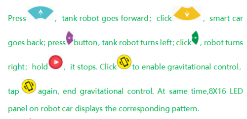
Project 15: Multi-purpose Robot Car
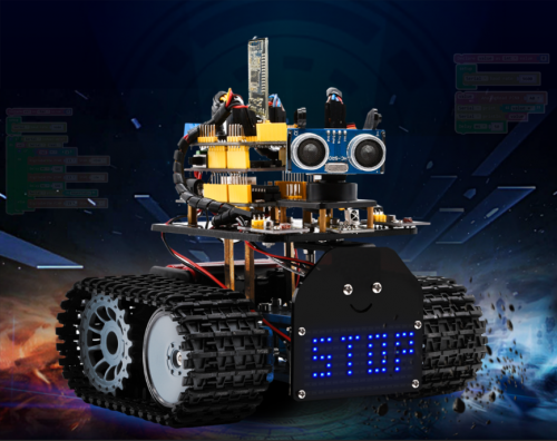
(1)Description
In previous projects, the tank car only performs single function, however, in this lesson, we integrate all of function to control smart car via Bluetooth control.
Here is a simple flow chart of multi-purpose robot car as for your reference.
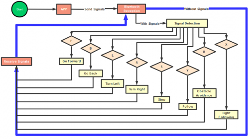
(2)Connection Diagram
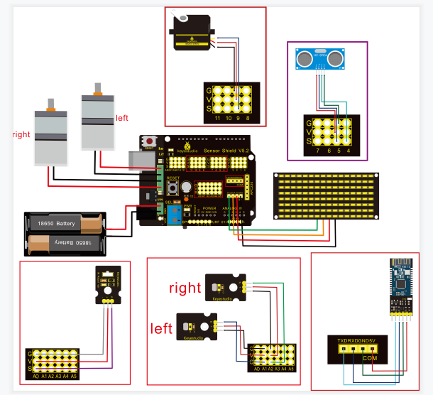
Attention:Confirm that every component is connected.
Wire-up Guide:
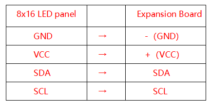
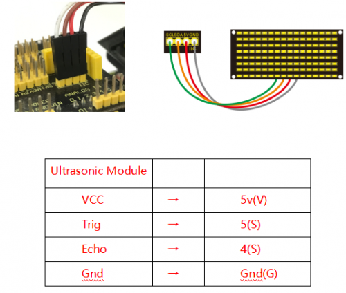
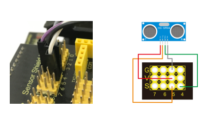
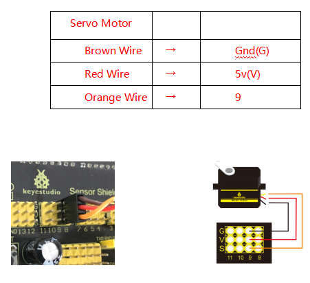
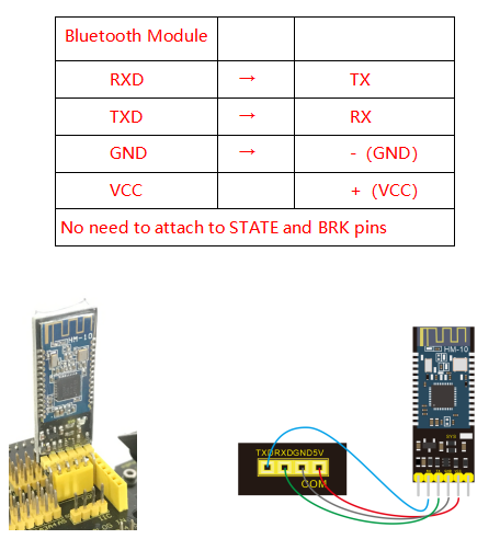
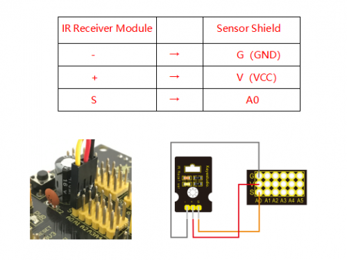
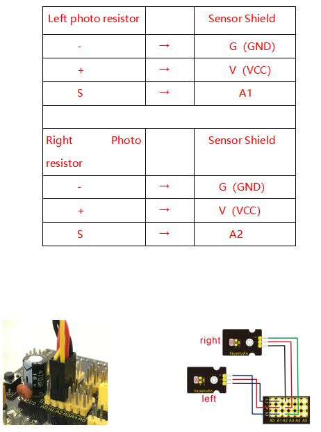
(3)Test Code
    /*
 keyestudio Mini Tank Robot v2.0
 lesson 15
 multiple functions
 http://www.keyestudio.com
*/

//Array, used to store the data of the pattern, can be calculated by yourself or obtained from the modulus tool
unsigned char start01[] = {0x01,0x02,0x04,0x08,0x10,0x20,0x40,0x80,0x80,0x40,0x20,0x10,0x08,0x04,0x02,0x01};
unsigned char front[] = {0x00,0x00,0x00,0x00,0x00,0x24,0x12,0x09,0x12,0x24,0x00,0x00,0x00,0x00,0x00,0x00};
unsigned char back[] = {0x00,0x00,0x00,0x00,0x00,0x24,0x48,0x90,0x48,0x24,0x00,0x00,0x00,0x00,0x00,0x00};
unsigned char left[] = {0x00,0x00,0x00,0x00,0x00,0x00,0x44,0x28,0x10,0x44,0x28,0x10,0x44,0x28,0x10,0x00};
unsigned char right[] = {0x00,0x10,0x28,0x44,0x10,0x28,0x44,0x10,0x28,0x44,0x00,0x00,0x00,0x00,0x00,0x00};
unsigned char STOP01[] = {0x2E,0x2A,0x3A,0x00,0x02,0x3E,0x02,0x00,0x3E,0x22,0x3E,0x00,0x3E,0x0A,0x0E,0x00};
unsigned char clear[] = {0x00,0x00,0x00,0x00,0x00,0x00,0x00,0x00,0x00,0x00,0x00,0x00,0x00,0x00,0x00,0x00};
#define SCL_Pin  A5  //Set clock pin to A5
#define SDA_Pin  A4  //Set data pin to A4

#define ML_Ctrl 13  //define direction control pin of left motor
#define ML_PWM 11   //define PWM control pin of left motor
#define MR_Ctrl 12  //define direction control pin of right motor
#define MR_PWM 3   //define PWM control pin of right motor

#define Trig 5  //ultrasonic trig Pin
#define Echo 4  //ultrasonic echo Pin
int distance; //save the distance value detected by ultrasonic, follow function
int random2; //save the variable of random numberssave the variable of random numbers
//save the distance value detected by ultrasonic, obstacle avoidance function
int a;
int a1;
int a2;

#define servoPin 9  //servo Pin
int pulsewidth;

#define light_L_Pin A1   //define the pin of left photo resistor sensor
#define light_R_Pin A2   //define the pin of right photo resistor sensor
int left_light;
int right_light;

char bluetooth_val; //save the value of Bluetooth reception
int flag;  //flag variable, it is used to entry and exist function
void setup(){
  Serial.begin(9600);
  pinMode(Trig, OUTPUT);
  pinMode(Echo, INPUT);
  pinMode(ML_Ctrl, OUTPUT);
  pinMode(ML_PWM, OUTPUT);
  pinMode(MR_Ctrl, OUTPUT);
  pinMode(MR_PWM, OUTPUT);

  pinMode(servoPin, OUTPUT);
  procedure(90); //set servo to 90°
 pinMode(SCL_Pin,OUTPUT);
  pinMode(SDA_Pin,OUTPUT);
  matrix_display(clear);    //Clear the display
  matrix_display(start01);  //display start pattern
  pinMode(light_L_Pin, INPUT);
  pinMode(light_R_Pin, INPUT);
}

void loop(){
  if (Serial.available())
  {
    bluetooth_val = Serial.read();
    Serial.println(bluetooth_val);
  }
  switch (bluetooth_val)
  {
    case 'F':  //Forward instruction
      Car_front();
      matrix_display(front);  //display forward pattern
      break;
    case 'B':  //Back instruction
      Car_back();
      matrix_display(back);  // display back pattern
      break;
    case 'L':  //left-turning instruction
      Car_left();
      matrix_display(left);  //show left-turning pattern
      break;
    case 'R':  //right-turning instruction
      Car_right();
      matrix_display(right);  //show right-turning pattern
      break;
    case 'S':  //stop instruction
      Car_Stop();
      matrix_display(STOP01);  //display stop pattern
      break;
   case 'Y':
      matrix_display(start01);  //show start pattern
      follow();
      break;
   case 'U':
      matrix_display(start01);  //show start pattern
      avoid();
      break;
   case 'X':
      matrix_display(start01);  //show start pattern
      light_track();
      break;
  }}
/*****************Obstacle Avoidance Function**************/
void avoid()
{
  flag = 0;  //the design that enter obstacle avoidance function
  while (flag == 0)
  {
    random2 = random(1, 100);
    a = checkdistance();  //assign the front distance detected by ultrasonic sensor to variable a

    if (a < 20) //when the front distance detected is less than 20cm
    {
      Car_Stop();  //robot stops
      delay(200); //delay in 200ms

      procedure(160);  //Ultrasonic platform turns left
      for (int j = 1; j <= 10; j = j + (1)) { ///for statement, the data will be more accurate if ultrasonic sensor detect a few times.
        a1 = checkdistance();  //assign the left distance detected by ultrasonic sensor to variable a1
      }
      delay(200);
      procedure(20); //Ultrasonic platform turns right
      for (int k = 1; k <= 10; k = k + (1)) {
        a2 = checkdistance(); //assign the right distance detected by ultrasonic sensor to variable a2
      }
      if (a1 < 50 || a2 < 50)  //robot will turn to the longer distance side when left or right distance is less than 50cm.if the left or right distance is less than 50cm, the robot will turn to the greater distance
      {
        if (a1 > a2) //left distance is greater than right
        {
          procedure(90);  //Ultrasonic platform turns back to right ahead ultrasonic platform turns front
          Car_left();  //robot turns left
          delay(500);  //turn left 500ms
          Car_front(); //go forward
        }
        else
        {
          procedure(90);
          Car_right(); //robot turns right
          delay(500);
          Car_front();  //go forward
        }
      }
      else  //both distance on two side is greater than or equal to 50cm, turn randomly
      {
        if ((long) (random2) % (long) (2) == 0)  //when the random number is even
        {
          procedure(90);
          Car_left(); //robot turns left
          delay(500);
          Car_front(); //go forward
        }
        else
        {
          procedure(90);
          Car_right(); //robot turns right
          delay(500);
          Car_front(); ///go forward
       } } }
  else  //If the front distance is greater than or equal to 20cm, robot car will go front
  {
      Car_front(); //go forward
  }
  // receive the Bluetooth value to end the obstacle avoidance function
  if (Serial.available())
  {
    bluetooth_val = Serial.read();
    if (bluetooth_val == 'S')  //receive S
    {
      flag = 1;  //when assign 1 to flag, end loop
    }}}}
/*******************Follow****************/
void follow() {
  flag = 0;
  while (flag == 0) {
    distance = checkdistance();  //assign the distance detected by ultrasonic sensor to distance
    if (distance >= 20 && distance <= 60) //the range to go front
    {
      Car_front();
    }
    else if (distance > 10 && distance < 20)  //the range to stop
    {
      Car_Stop();
    }
    else if (distance <= 10)  // the range to go back
    {
      Car_back();
    }
    else  //other situations, stop
    {
      Car_Stop();
    }
    if (Serial.available())
    {
      bluetooth_val = Serial.read();
      if (bluetooth_val == 'S')
      {
        flag = 1;  //end loop
      }}}}
//The function to control ultrasonic sensor the function controlling ultrasonic sensor
float checkdistance() {
  digitalWrite(Trig, LOW);
  delayMicroseconds(2);
  digitalWrite(Trig, HIGH);
  delayMicroseconds(10);
  digitalWrite(Trig, LOW);
  float distance = pulseIn(Echo, HIGH) / 58.00;  //58.20 means 2*29.1=58.2
  delay(10);
  return distance;
}
//The function to control servo the function controlling servo
void procedure(int myangle) {
  for (int i = 0; i <= 50; i = i + (1)) {
    pulsewidth = myangle * 11 + 500;
    digitalWrite(servoPin,HIGH);
    delayMicroseconds(pulsewidth);
    digitalWrite(servoPin,LOW);
    delay((20 - pulsewidth / 1000));
  }}

/****************Light Follow******************/
void light_track() {
  flag = 0;
  while (flag == 0) {
    left_light = analogRead(light_L_Pin);
    right_light = analogRead(light_R_Pin);
    if (left_light > 650 && right_light > 650) //the value detected by photo resistor, go forward
    {
      Car_front();
    }
    else if (left_light > 650 && right_light <= 650)  //the value detected by photo resistor, turn left
    {
      Car_left();
    }
    else if (left_light <= 650 && right_light > 650) //the value detected by photo resistor, turn right
    {
      Car_right();
    }
    else  //other situations, stop
    {
      Car_Stop();
    }
    if (Serial.available())
    {
      bluetooth_val = Serial.read();
      if (bluetooth_val == 'S') {
        flag = 1;
     }}}}
/***************Dot Matrix *****************/
// this function is used for dot matrix display
void matrix_display(unsigned char matrix_value[])
{
  IIC_start();
  IIC_send(0xc0);  //Choose address

  for(int i = 0;i < 16;i++) //pattern data has 16 bits
  {
     IIC_send(matrix_value[i]); //convey the pattern data
  }
  IIC_end();   //end the transmission of pattern data
  IIC_start();
  IIC_send(0x8A);  //display control, set pulse width to 4/16
  IIC_end();
}
//The condition starting to transmit data
void IIC_start()
{
  digitalWrite(SCL_Pin,HIGH);
  delayMicroseconds(3);
  digitalWrite(SDA_Pin,HIGH);
  delayMicroseconds(3);
  digitalWrite(SDA_Pin,LOW);
  delayMicroseconds(3);
}
//convey data
void IIC_send(unsigned char send_data)
{
  for(char i = 0;i < 8;i++)  //each byte has 8 bits
  {
      digitalWrite(SCL_Pin,LOW);  //pull down clock pin SCL Pin to change the signals of SDA
      delayMicroseconds(3);
      if(send_data & 0x01)  //set high and low level of SDA_Pin according to 1 or 0 of every bit
      {
        digitalWrite(SDA_Pin,HIGH);
      }
      else
      {
        digitalWrite(SDA_Pin,LOW);
      }
      delayMicroseconds(3);
      digitalWrite(SCL_Pin,HIGH); //pull up clock pin SCL_Pin to stop transmitting data
      delayMicroseconds(3);
      send_data = send_data >> 1;  // detect bit by bit, so move the data right by one
  }}
//The sign that data transmission ends
void IIC_end()
{
  digitalWrite(SCL_Pin,LOW);
  delayMicroseconds(3);
  digitalWrite(SDA_Pin,LOW);
  delayMicroseconds(3);
  digitalWrite(SCL_Pin,HIGH);
  delayMicroseconds(3);
  digitalWrite(SDA_Pin,HIGH);
  delayMicroseconds(3);
}
/*************the function to run motor*************/
void Car_front()
{
  digitalWrite(MR_Ctrl,LOW);
  analogWrite(MR_PWM,200);
  digitalWrite(ML_Ctrl,LOW);
  analogWrite(ML_PWM,200);
}
void Car_back()
{
  digitalWrite(MR_Ctrl,HIGH);
  analogWrite(MR_PWM,200);
  digitalWrite(ML_Ctrl,HIGH);
  analogWrite(ML_PWM,200);
}
void Car_left()
{
  digitalWrite(MR_Ctrl,LOW);
  analogWrite(MR_PWM,255);
  digitalWrite(ML_Ctrl,HIGH);
  analogWrite(ML_PWM,255);
}
void Car_right()
{
  digitalWrite(MR_Ctrl,HIGH);
  analogWrite(MR_PWM,255);
  digitalWrite(ML_Ctrl,LOW);
  analogWrite(ML_PWM,255);
}
void Car_Stop()
{
  digitalWrite(MR_Ctrl,LOW);
  analogWrite(MR_PWM,0);
  digitalWrite(ML_Ctrl,LOW);
  analogWrite(ML_PWM,0);
}
void Car_T_left()
{
  digitalWrite(MR_Ctrl,LOW);
  analogWrite(MR_PWM,255);
  digitalWrite(ML_Ctrl,LOW);
  analogWrite(ML_PWM,180);
}
void Car_T_right()
{
  digitalWrite(MR_Ctrl,LOW);
  analogWrite(MR_PWM,180);
  digitalWrite(ML_Ctrl,LOW);
  analogWrite(ML_PWM,255);
}
(4)Test Result
Note:Remove the Bluetooth module before uploading test code, otherwise, you will fail to upload test code. Reconnect Bluetooth module after uploading test code
Upload test code successfully, insert Bluetooth module, power on, and connect to Bluetooth. The tank robot can show distinct function by App.
Alright, the whole projects are finished. Please feel free to contact us if you confront some problems.
There are some hot-selling items below. You could log in our website to browse them if you’re interested.
9. Resources
Wiki page:https://wiki.keyestudio.com/Ks0428_keyestudio_Mini_Tank_Robot_V2
Official website: https://keyestudio.com/
Assembly Video Link: http://video.keyestudio.com/ks0428/
If you want to try with Mixly software, enter https://fs.keyestudio.com/KS0428.
Показаны 1 — 30 из 1 430 товаров
Показаны 1 — 30 из 1 430 товаров
Доставка remote control robot smart
Оформив покупку у нас Вы 100% заберете свой заказанный товар в самые короткие сроки !
Ведь купить товар из-за рубежа не так просто, а мы с легкостью организуем почтовую пересылку по всей России (доставка организована в Казахстан,Украину,Беларусию и т.д.) .
На этой странице указаны особенности и техническая спецификация товара, доставка бесплатна и цена (указана в рублях) на все товары на нашем сайте окончательна (доплачивать при получении посылки не нужно).
Страхование всех посылок заказанных у нас является гарантией получения товара , а грамотные специалисты помогут Вам купить remote control robot smart без особых проблем и получить только радость от покупки .
Вы также можете воспользоваться нашим онлайн-каталогом для поиска других товаров (более 300 миллионов товаров со всего мира ) , которые мы тоже можем заказать для Вас . Уже более 60 000 человек оценили убоство работы с нашей компанией.
Купить remote control robot smart
Если Вы ищите сайт, где можно найти много разных remote control robot smart то Вы попали по адресу! У нас можно купить с доставкой по России.
Все посылки заказываемые через нашу компанию застрахованы и это 100% гарантия получения товара . Квалифицированная служба поддержки поможет Вам, проконсультирует по потребительским свойствам , что позволит получить только радость и хорошие эмоции от покупки.
Если Вы пролистаете страницу Выше, то найдете таблицу,где указаны все технические характеристики и особенности.
Доставка в Ваш город бесплатна, а ценовое предложение указанно в рублях (на все товары в нашем огромном онлайн-каталоге) — окончательна(доплата при получении заказа на почте не потребуется).
Мы занимаемся доставкой товаров из-за рубежа уже более 10 лет , что позволяет со 100% гарантией утверждать ,
что мы купим remote control robot smart и сделаем его пересылку до Вас быстрой и безопасной, без затягивания сроков и любых проблем.
Воспользуйтесь нашим онлайн-каталогом, чтобы найти другие товары т.к. в них находится больше чем 300 000 000 лотов со всего мира,
которые мы тоже можем заказать для Вас.
Гарантия на remote control robot smart
Купив у нас Вы гарантированно получите свою покупку как указано в описании и в самые короткие сроки! Мы организуем доставку по всей России.
Вы также можете воспользоваться нашим каталогом для поиска других товаров ( более 300 миллионов товаров со всего мира ) , которые мы тоже можем заказать для Вас.
Мы предлагаем супер-цену на remote control robot smart, а также Вы бесплатно получаете возможность воспользоваться нашей расширенной программой защиты покупателя и бесплатной доставкой. Цена указана в рублях на все товары в этой категории окончательна .
Все заказы застрахованы на 5 000 000 (пять миллионов рублей) в СК «Гелиос».
Случайный отзыв о нашей работе
На удивление очень быстро! Боялся, вдруг сломают иглу для проигрывателя… но, упаковка такая, что можно её сломать- уничтожить, если специально лупить по упаковку молотком.
С П А С И Б О ! ! !. Автор Михаил Анатольевич. Дата 2021-01-11. Населенный пункт: Москва
На данной странице представлены и доступны для скачивания и печати инструкции по настройке, установке и эксплуатации устройств Xiaomi на русском языке , а также руководства пользователя. Данный материал является вспомогательным и ознакомительным для пользователя.
(!) Для того, чтобы открыть и скачать (распечатать) инструкцию, найдите название нужного товара в списке и нажмите «Инструкция тут» справа от названия.
(!) Для того, чтобы скачать для личного пользования или распечатать инструкцию, откройте её, нажав на «Инструкция тут» и, в открывшемся окне, нажмите на кнопку нужного действия в верхней правой части экрана.
Инструкции к разделу «Бытовая техника»:
• Беспроводной ручной пылесос JIMMY Handheld Wireless Powerful Vacuum Cleaner JV51 — Инструкция тут
• Беспроводной ручной пылесос Jimmy Lake Mites Vacuum Cleaner JV71 — Инструкция тут
• Беспроводной ручной пылесос Viomi A9 Handheld Wireless Vacuum Cleaner — Инструкция тут
• Беспроводная электрическая швабра (полотёр) SWDK WOW Electric Mop (D260) — Инструкция тут
• Вертикальный беспроводной пылесос Xiaomi Roidmi F8 Storm Vacuum Cleaner Handheld Wireless (XCQ01RM) — Инструкция тут
• Мотор умного электро-карниза Xiaomi Aqara Smart Curtain Controller — Инструкция тут
• Обогреватель конвекторный Xiaomi SmartMi Electric Heater Smart Edition (DNQZNB03ZM) — Инструкция тут
• Ручной отпариватель Deerma Portable Steam Ironing DEM-HS200 — Инструкция тут
• Стационарный блендер Xiaomi Pinlo Little Monster Cooking Machine — Инструкция тут
• Сушилка для белья Xiaolang Intelligent Clothes Disinfection Dryer 35L — Инструкция тут
• Умная рисоварка (мультиварка) Xiaomi MiJia Induction Heating Pressure Rice Cooker — Инструкция тут
• Умное мусорное ведро Xiaomi Mijia Townew Smart Trash Smart Bin 15.5 — Инструкция тут
• Умный дверной замок Mijia Smart Door Lock — Инструкция тут
• Умный робот-пылесос Xiaomi Mi Robot Vacuum Cleaner — Инструкция тут
• Умный робот-пылесос Xiaomi Mi Robot Vacuum Mop — Инструкция тут
• Умный робот-пылесос Xiaomi Mi Robot Vacuum Mop 1C — Инструкция тут
• Умный робот-пылесос Xiaomi Mi Robot Vacuum Cleaner 1S — Инструкция тут
• Умный чайник c контролем температуры Xiaomi MiJia Smart Temperature Control Kettle — Инструкция тут
• Умный чайник Viomi Smart Kettle Bluetooth Pro — Инструкция тут
• Чайник-заварник Xiaomi Deerma Multi Function Electric HeatK ettle — Инструкция тут
• Фильтр-кувшин для воды Xiaomi Viomi Kettle L1 UV — Инструкция тут
• Электрический чайник Xiaomi MiJia Electric Water Kettle (v.2) 1.5L — Инструкция тут
• Робот-пылесос с базой самоочистки Viomi Robot Vacuum Cleaner S9 — Инструкция тут
• Моющий умный робот-пылесос Xiaomi Mi Robot Vacuum Mop Pro — Инструкция тут
• Обогреватель конвекторный SmartMi Zhimi Electric Warmer Chi Meters Heater White (DNQ01ZM) — Инструкция тут
• Моющий умный робот-пылесос Roborock Smart Sweeping Vacuum Cleaner S7 — Инструкция тут
• Моющий умный робот-пылесос Roborock Sweep One S5 MAX — Инструкция тут
• Швабра Blue Fish Rotating Mop — Инструкция тут
• Беспроводной пылесос Xiaomi Mi Handheld Vacuum Cleaner Pro G10 — Инструкция тут
• Швабра Deerma Mop Up Body Mop (DEM-TB900) — Инструкция тут
• Беспроводной ручной пылесос Roborock H6 (H6M1A) — Инструкция тут
• Блендер Jimmy B32 Cooking Machine — Инструкция тут
• Беспроводной ручной пылесос Jimmy Handheld Cordless Vacuum Cleaner JV85 — Инструкция тут
• Беспроводной ручной пылесос Deerma Wireless Vacuum Cleaner VC01 — Инструкция тут
• Беспроводной ручной пылесос Jimmy Lake Mites Vacuum Cleaner JV71 — Инструкция тут
• Беспроводной ручной пылесос Jimmy Handheld Vacuum Cleaner H9 Pro — Инструкция тут
• Беспроводной ручной пылесос Jimmy Wireless Vacuum Cleaner JV53 — Инструкция тут
• Блендер Jimmy B53 Cooking Machine — Инструкция тут
• Многофункциональный пароочиститель Deerma Steam Cleaner DEM-ZQ610 — Инструкция тут
• Беспроводной ручной пылесос Dreame Cordless Stick Vacuum P10 — Инструкция тут
• Беспроводной ручной пылесос Dreame Cordless Stick Vacuum P10 Pro — Инструкция тут
Инструкции к разделу «Роботы-пылесосы»:
• Моющий умный робот-пылесос Smartmi A1 VortexWave Robot Vacuum Cleaner — Инструкция тут
• Моющий умный робот-пылесос Dreame Robot Vacuum Cleaner L10 Pro — Инструкция тут
• Робот-пылесос с базой самоочистки Dreame Bot Z10 Pro — Инструкция тут
• Моющий умный робот-пылесос Dreame Robot Vacuum Cleaner F9 — Инструкция тут
• Моющий умный робот-пылесос Dreame Robot Vacuum Cleaner D9 — Инструкция тут
• Моющий умный робот-пылесос Dreame Robot Vacuum Cleaner D9 Pro — Инструкция тут
• Моющий умный робот-пылесос Roborock Smart Sweeping Vacuum Cleaner S6 (T65) — Инструкция тут
• Моющий умный робот-пылесос Xiaomi Mi Robot Vacuum-Mop Essential G1(MJSTG1) — Инструкция тут
• Моющий умный робот-пылесос Xiaomi Mi Roborock Sweep One — Инструкция тут
• Моющий умный робот-пылесос Xiaomi Mi Robot Vacuum Mop Pro — Инструкция тут
• Моющий умный робот-пылесос Xiaowa Sweeper Robot Planning E202 — Инструкция тут
• Робот-пылесос Viomi Cleaning Robot V2 (V-RVCLM21B) — Инструкция тут
Инструкции к разделу «Умные часы, фитнес браслеты, GPS трекеры»:
• Умные часы (фитнес трекер) Amazfit Bip — Инструкция тут
• Фитнес браслет с пульсометром Xiaomi Mi Band 3 — Инструкция тут
• Фитнес браслет с пульсометром Xiaomi Mi Smart Band 6 — Инструкция тут
• Фитнес браслет с пульсометром Xiaomi Huami Amazfit Arc — Инструкция тут
• Фитнес браслет Xiaomi Mi Amazfit — Инструкция тут
• Фитнес-браслет с пульсометром Xiaomi Mi Smart Band 5 — Инструкция тут
• Фитнес браслет с пульсометром Xiaomi Mi Smart Band 4 — Инструкция тут
• Фитнес браслет с пульсометром Xiaomi Mi Smart Band 4C — Инструкция тут
• Фитнес-браслет с пульсометром Amazfit Band 5 (A2005) — Инструкция тут
Инструкции к разделу «Умное освещение»:
• Настольная лампа Yeelight Smart Adjustable Desk Lamp — Инструкция тут
• Потолочная лампа Yeelight Smart LED Ceiling Lamp 400mm (YLXD07YL) — Инструкция тут
• Потолочная лампа Yeelight Smart LED Ceiling Lamp — Инструкция тут
• Потолочная лампа Yeelight Smart LED Ceiling Lamp Pro — Инструкция тут
• Прикроватная лампа Xiaomi Yeelight LED Bedside Lamp D2 (YLCT01YL) — Инструкция тут
• Пульт дистанционного управления для потолочной лампы Mijia/YeelightRemoteControl — Инструкция тут
• Умная лампа Aqara LED Light Bulb E27 — Инструкция тут
• Умная лампа Xiaomi Mi LED Smart Bulb IPL E27 — Инструкция тут
• Умная настольная лампа-ночник Xiaomi MiJia Bedside Lamp — Инструкция тут
• Умная настольная лампа-ночник Xiaomi Mijia Bedside Lamp 2 (MJCTD02YL) — Инструкция тут
• Умная настольная лампа Xiaomi Mi Led Desk Lamp 1S (MUE4105GL) — Инструкция тут
• Умная настольная лампа Xiaomi Philips EyeCare Smart Lamp 2 — Инструкция тут
• Умная настольная лампа Xiaomi Mi LED White — Инструкция тут
• Умная настольная лампа Yeelight Led Table Lamp — Инструкция тут
• Умная потолочная лампа (люстра) Xiaomi Mi MiJia LED Ceiling Light (MJXDD01YL) — Инструкция тут
• Умная светодиодная лента Yeelight Google Home Lightstrips Plus IPL — Инструкция тут
• Умный ночник с датчиком движения Xiaomi MiJia LED Corridor Night Light — Инструкция тут
• Умный ночник-свеча Yeelight Candela Ambiance Lamp Smart Atmosphere Light (YLFW01YL) — Инструкция тут
• Умный ночник Xiaomi Mi Motion-Activated Night Light 2 (MUE4115GL) — Инструкция тут
• Умный потолочный светильник-люстра Yeelight Smart Meteorite LED — Инструкция тут
• Умный потолочный светильник Xiaomi Philips LED Ceiling Lamp — Инструкция тут
• Умная светодиодная лампочка Xiaomi Mi Smart LED Bulb Essential (GPX4021GL) — Инструкция тут
• Потолочная лампа Xiaomi Mi Smart LED Ceiling Light 450mm (MJXDD01SYL) — Инструкция тут
• Умный ночник-свеча Yeelight Candela Lamp (YLFW01YL) — Инструкция тут
Инструкции к разделу «Mi Wifi»:
• WiFi Усилитель сигнала Xiaomi Mi WiFi Amplifier 2 — Инструкция тут
• WiFi усилитель сигнала Xiaomi Mi Wi-Fi Range Extender Pro — Инструкция тут
• WiFi Роутер Xiaomi Mi WiFi Router 4a Gigabit Edition — Инструкция тут
Инструкции к разделу «Видеорегистраторы»:
• Автомобильный видеорегистратор Xiaomi Yi Smart Dash Camera DVR — Инструкция тут
• Автомобильный видеорегистратор Xiaomi MiJia Car DVR Driving Recorder Camera — Инструкция тут
• Видеорегистратор 70mai Dash Cam A800 (Midrive D09) — Инструкция тут
Инструкции к разделу «Экшен камеры»:
• Сферическая экшен камера Xiaomi MiJia 360 Sphere Panoramic Camera — Инструкция тут
• Экшн камера Xiaomi Yi 4K Action Camera 2 — Инструкция тут
• Экшн камера Xiaomi MiJia 4K Action Camera — Инструкция тут
• Экшн камера Xiaomi Yi Action Camera — Инструкция тут
Инструкции к разделу «IP камеры»:
• IP камера видеонаблюдения Xiaomi Yi Mijia 360° Home Camera — Инструкция тут
• IP камера с панорамной съемкой Xiaomi Mi Home Security Camera 360° 1080P — Инструкция тут
• IP камера видеонаблюдения Xiaomi Yi Home Camera (720p) — Инструкция тут
• IP камера с панорамной съемкой Xiaomi Mi Home Security Camera 360° 2K Pro (MJSXJ06CM) — Инструкция тут
• Уличная IP камера видеонаблюдения IMILAB EC3 Outdoor Security Camera (CMSXJ25A) — Инструкция тут
Инструкции к разделу «Сенсоры и датчики»:
• Автомобильный датчик давления в шинах 70 Mai Tire Pressure Monitor T01 — Инструкция тут
• Беспроводной контроллер Xiaomi Mi Smart Home Cube — Инструкция тут
• Датчик протечки Xiaomi Aqara Flood Sensor — Инструкция тут
• Датчик вибрации Aqara Vibration Sensor — Инструкция тут
• Датчик освещенности Xiaomi Mijia Light Sensor — Инструкция тут
• Датчик температуры, давления и влажности Aqara Temperature Humidity Sensor (WSDCGQ11LM) — Инструкция тут
• Набор датчиков для умного дома Xiaomi Mi Smart Sensor Set — Инструкция тут
• Умная розетка Xiaomi Aqara Smart Wall Socket — Инструкция тут
• Умный выключатель Aqara Smart Light Control — Инструкция тут
• Унивеpсальный пульт ДУ Xiaomi Mi Smart Home All-In-One Media Control Center — Инструкция тут
• Универсальный анализатор для растений Xiaomi Mi Smart Flower and Plant Monitor Huahuacaocao — Инструкция тут
• Часы с датчиком температуры и влажнлсти Xiaomi Mijia Temperature and Humidity Electronic Watch — Инструкция тут
• Центр управления умным домом Aqara Hub M2 (HM2-G01) — Инструкция тут
• Умный дверной замок Aqara Smart Door Lock N100 — Инструкция тут
• Датчик температуры и влажности Xiaomi Mi Temperature and Humidity Monitor 2 — Инструкция тут
• Умный мотор для штор с карнизом Yeelight Smart Electric Curtain Motor & Stitching Track (YLDJ001) — Инструкция тут
• Умная розетка Aqara Smart Plug (SP-EUC01) — Инструкция тут
• Беспроводная кнопка (коммутатор) Aqara Smart Wireless Switch — Инструкция тут
• Умный выключатель Aqara Wireless Remote Switch Single Rocker — Инструкция тут
• Мотор для рулонных штор Aqara Roller Shade Controller — Инструкция тут
• Двухканальный модуль-реле Aqara Wireless Relay — Инструкция тут
• Центр управления умным домом Aqara Hub M1S (HM1S-G01) — Инструкция тут
• Датчик движения с креплением Aqara Smart Home Human Body Sensor & Light Intensity Sensors — Инструкция тут
• Беспроводной датчик движения Xiaomi Mi Smart Home Occupancy Sensor — Инструкция тут
Инструкции к разделу «Красота и здоровье»:
• Беспроводной ирригатор для полости рта Soocas W3 — Инструкция тут
• Детский термометр Xiaomi Smart Thermometer Miaomiaoce — Инструкция тут
• Портативная электробритва Soocas Smooth Electric Shaver Ling Lang S3 — Инструкция тут
• Умная крышка-биде Xiaomi Smart toilet Cover — Инструкция тут
• Умные напольные весы Xiaomi Mi Smart Scale — Инструкция тут
• Умные напольные весы Xiaomi Mi Body Composition Scale — Инструкция тут
• Электрическая зубная щетка Xiaomi Oclean One Smart Sonic Eleсtric Toothbrush — Инструкция тут
• Электрическая зубная щетка Xiaomi MiJia SOOCAS X3 Clean Smart Electric Toothbrush — Инструкция тут
• Электрический термометр Xiaomi iHealth Smart Thermometer — Инструкция тут
• Электрическая зубная щетка Soocas X5 Smart Electric Toothbrush — Инструкция тут
• Электробритва c плавающей головкой Xiaomi MiJia 360 Degree Float Electric Shaver (MJTXD01SKS) — Инструкция тут
• Бесконтактный дозатор (диспенсер) для жидкого мыла Xiaomi Mijia Automatic Foam Soap Dispenser — Инструкция тут
• Умные напольные весы Xiaomi Mi Smart Scale 2 — Инструкция тут
• Дозатор для жидкого мыла Enchen Coco Hand Washer — Инструкция тут
• Электрическая зубная щётка Xiaomi Mi Sonic Electric Toothbrush T500 — Инструкция тут
• Аппарат для ультразвуковой чистки лица Inface Electronic Sonic Beauty Facial (MS2000) — Инструкция тут
• Умные напольные весы Xiaomi Mi Body Composition Scale 2 — Инструкция тут
• Электробритва Xiaomi Mijia Electric Shaver S500 — Инструкция тут
• Беспроводной ирригатор для полости рта Soocas W3 — Инструкция тут
• Беспроводной ирригатор для полости рта Soocas W3 PRO — Инструкция тут
Инструкции к разделу «Наушники»:
• Вакуумные наушники Xiaomi Mi In-Ear Headphones Pro Hybrid — Инструкция тут
• Беспроводные наушники Xiaomi Mi True Wireless Earbuds Basic 2 (AirDots 2) — Инструкция тут
Инструкции к разделу «Контроль воздуха»:
• Увлажнитель Smartmi Humidifier Rainforest CJJSQ06ZM — Инструкция тут
• Очиститель воздуха Smartmi Air Purifier P1 — Инструкция тут
• Очиститель воздуха Xiaomi Mi Air Purifier Pro — Инструкция тут
• Очиститель воздуха Xiaomi Mi Air Purifier 2S — Инструкция тут
• Очиститель воздуха Xiaomi Mi Air Purifier 3H — Инструкция тут
• Увлажнитель воздуха Xiaomi Deerma Air Humidifier 5L — Инструкция тут
• Увлажнитель воздуха Deerma Air Humidifier DEM-F600 — Инструкция тут
• Увлажнитель воздуха Deerma Air Humidifier DEM-F628 — Инструкция тут
• Увлажнитель воздуха Xiaomi Mijia Intelligent Sterilization Humidifier (SCK0A45) — Инструкция тут
• Увлажнитель воздуха Xiaomi Smartmi Evaporative Humidifier (CJXJSQ02ZM) — Инструкция тут
Инструкции к разделу «Качество воды»:
Инструкции к разделу «Аксессуары для умного дома»:
• Сменный полипропиленовый фильтр №1 PP для Xiaomi Mi Water Purifier — Инструкция тут
• Сменный угольный фильтр предварительной очистки №2 CI для Xiaomi Mi Water Purifier — Инструкция тут
Инструкции к разделу «TV box»:
• Цифровая TV приставка для телевизора Xiaomi Mi Miui TV Box S (MDZ-22-AB) — Инструкция тут
• Цифровая TV приставка для телевизора Xiaomi Mi Box Pro 4K — Инструкция тут
Инструкции к разделу «Телевизоры и проекторы»:
• Лазерный проектор Xiaomi MiJia Laser Projection TV 150 inches — Инструкция тут
• Телевизор Xiaomi Mi TV 2 55 — Инструкция тут
Инструкции к разделу «Электросамокаты, гироскутеры, моноколеса»:
• Умный электросамокат Xiaomi MiJia Electric Scooter — Инструкция тут
• Умный электросамокат Xiaomi Mijia Electric Scooter Pro — Инструкция тут
Инструкции к разделу «Стиль жизни»:
• Автомобильный компрессор 70mai Air Compressor (Midrive TP01) — Инструкция тут
• Портативный фонарик Xiaomi LED Minimalist Portable Electric Torch Flashlight (LPB01ZM) — Инструкция тут
• Чемодан Xiaomi Mi Trolley 90 Points 24 дюйма — Инструкция тут
• Чемодан Xiaomi Suitcase Luggage Classic Series 20 дюймов — Инструкция тут
• Чемодан Xiaomi RunMi 90 Points Smart Metal Suitcase 20 дюймов — Инструкция тут
• Храповая отвертка с набором бит (16 в 1) Xiaomi Mi Ratchet Screwdriver — Инструкция тут
Инструкции к разделу «Портативные зарядные устройства»:
• Зарядно-пусковое устройство Power Bank 11100mAh 70mai Jump Starter (Midrive PS01) — Инструкция тут
• Портативное зарядное устройство Xiaomi ZMI 10 Power Bank 20000 mAh Type-C (QB820) — Инструкция тут
• Портативное зарядное устройство Xiaomi Mi Power Bank 20.000 mAh — Инструкция тут
• Портативное зарядное устройство Xiaomi Mi Power Bank Pro 10.000 mAh — Инструкция тут
• Портативное зарядное устройство Xiaomi Mi Power Bank 2i 10000 mAh 2 USB (PLM09ZM) — Инструкция тут
• Портативное зарядное устройство Xiaomi Mi Power Bank ZMI Standard Edition 10000 mAh — Инструкция тут
• Портативное зарядное устройство Xiaomi Mi Power Bank 10400 mAh — Инструкция тут
• Портативное зарядное устройство Xiaomi Redmi Universal Power Bank 20.000 mAh — Инструкция тут
• Портативное зарядное устройство Xiaomi Mi Power Bank 3 10.000 mAh 2 USB (PLM13ZM) — Инструкция тут
Инструкции к разделу «Портативные колонки»:
• Портативная колонка Xiaomi Mi Square Box 2 Bluetooth Speaker — Инструкция тут
• Портативная колонка Xiaomi Mi Round 2 Bluetooth Speaker — Инструкция тут
• Портативная колонка Xiaomi Mi Internet Speaker 2 — Инструкция тут
• Портативная колонка Xiaomi Mi Portable Bluetooth Speaker — Инструкция тут
Инструкции к разделу «Блютуз гарнитура»:
• Беспроводная Bluetooth-гарнитура Xiaomi Mi Bluetooth Headset — Инструкция тут
• Адаптер для наушников Xiaomi Bluetooth Audio Receiver — Инструкция тут
Инструкции к разделу «Сетевые фильтры (удлинители)»:
• Умный удлинитель Xiaomi Mi Power Strip 3 розетки / 3 USB порта — Инструкция тут
• Умный удлинитель Xiaomi Mi Power Strip 3 розетки / 3 USB порта Русская версия — Инструкция тут
Инструкции к разделу «Аксессуары для камер»:
• Селфи монопод + пульт ДУ для экшен камеры Xiaomi Yi Action Camera — Инструкция тут
• Портативный трёхосевой электронный стабилизатор Handheld Gimbal (MJWDQ01FM) для MiJia Action Camera — Инструкция тут
• Аккумулятор для экшен камеры Xiaomi MiJia 4K Action Camera (RLDC01FM) — Инструкция тут
Инструкции к разделу «Мобильные аксессуары»:
• Беспроводное зарядное устройство Qi Xiaomi Universal Wireless Fast Charger — Инструкция тут
• Монопод Xiaomi Mi Wireless Monopod Bluetooth Selfie Stick — Инструкция тут
• Монопод-трипод Xiaomi Mi Selfie Stick Tripod — Инструкция тут
• Селфи монопод Xiaomi Mi Wired Monopod Selfie Stick — Инструкция тут
Инструкции к разделу «Аксессуары для ноутбуков и планшетов»:
• Беспроводная мышь Xiaomi Mi Portable Mouse (Wi-Fi + Bluetooth) — Инструкция тут
• Беспроводная мышь Xiaomi Mi Wireless Mouse (Wi-Fi) — Инструкция тут
• Мультисетевое зарядное устройство Xiaomi Multi Port USB Power Adapter — Инструкция тут
• Беспроводная мышь Xiaomi Mi Dual Mode Wireless Mouse Silent Edition — Инструкция тут
Инструкции к разделу «Аккумуляторы и батарейки»:
• Зарядное устройство Xiaomi ZI для перезаряжаемых батареек Ni-MH AA/AAA — Инструкция тут
Инструкции к разделу «Аксессуары для TV»:
• Пульт ДУ Xiaomi Box Remote Сontrol Bluetooth 2 — Инструкция тут
• Приставка Xiaomi Mi TV Stick (Android TV)
— Инструкция тут
Инструкции к разделу «Товары для животных»:
• Умная кормушка для животных Xiaowan Kitten&Puppy Smart Pet Feeder — Инструкция тут
Для работы проектов iXBT.com нужны файлы cookie и сервисы аналитики.
Продолжая посещать сайты проектов вы соглашаетесь с нашей
Политикой в отношении файлов cookie
Здравствуйте друзья
В этом обзоре я вернусь к уже неоднократно затрагиваемой мной тематике — управлением устройствами, которые изначально не поддерживают прямую интеграцию в умный дом. А посредником между ними и умным домом — будет служить универсальный пульт дистанционного управления, способный заменить собой любые инфракрасные и радио пульты.
Также мы рассмотрим пример добавления в Home Assistant не поддерживаемого штатно устройства из интеграции Broadlink. Будет много примеров, а в конце видео приведен рабочий кейс по управлению кондиционером из Home Assistant.
Содержание
- Где купить?
- Параметры
- Поставка
- Внешний вид
- Broadlink
- Добавление пультов
- Автоматизации
- Google Home
- Home Assistant
- Добавляем поддержку
- Подключение
- Отправка команд
- Удаление команд
- Кондиционер
- Видеоверсия обзора
- Вывод
Где купить?
Aliexpress — цена на момент публикации $31.90
Локально в Украине — INSTOR — цена на момент публикации 795 грн + Промокод на скидку 10% для покупки этого пульта (его надо сообщить менеджеру при покупке: KvazisRM4C
Параметры
- Модель — Broadlink BestCon RM4C Pro
- Беспроводный интерфейс — wi-fi 2.4 Ghz
- Частота для ИК диапазона — 38 kHz
- Частота для RF диапазона — 315 и 433 MHz
- Дальность работы ИК — до 8 метров
- Дальность работы RF — до 50 метров
- Питание — micro USB
- Потребляемая мощность — около 1 Ватта
- Условия работы — влажность до 85%, температура 0 — 50 С
- Размер — 45,7 х 50,1 мм
Поставка
В данном случае пульт был доставлен из локального украинского магазина, ссылку вы найдете в описании, так как стоимость была более чем конкурентна с Aliexpress. На белой коробке изображено устройство и указан бренд — BestCon
На задней стороне перечислены краткие технические параметры и есть еще одно важное упоминание — о работе с BroadLink, собственно поэтому я и вынес это слово в заглавие обзора. По сути это и есть BroadLink.
В коробке, кроме собственно универсального пульта, нашелся кабель питания USB — micro USB и пара инструкций, одна от производителя, другая от BroadLink. Блок питания в комплекте не идет, этот момент нужно учитывать.
Внешний вид
Устройство имеет вид небольшой бочки, однако в отличии от, так сказать, родных моделей BroadLink — дизайн тут немного сложнее и интереснее. Верхняя часть выполнена из темного, прозрачного для инфракрасных лучей, материала.
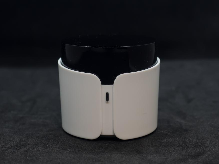
ИК диоды внутри — направлены по все стороны, так что как повернуть гаджет — разницы нет. Рядом с разъемом питания находится кнопка перевода и изменения режима сопряжения.
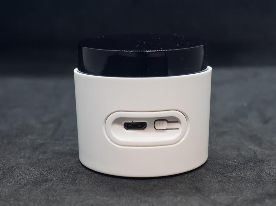
В нижней части по кругу сделана перфорация, хотя устройство совершенно не греется. В центре находится что-то вроде замка — защелки, хотя никаких креплений в комплекте нет.
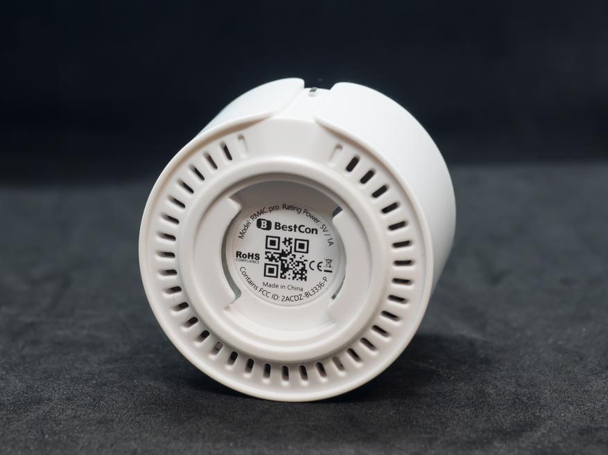
Для включения устройства — нужно при помощи комплектного кабеля подключить его к любому подходящему источнику питания — зарядке от телефона, удлинителю с USB, зарядной станции и т.п.
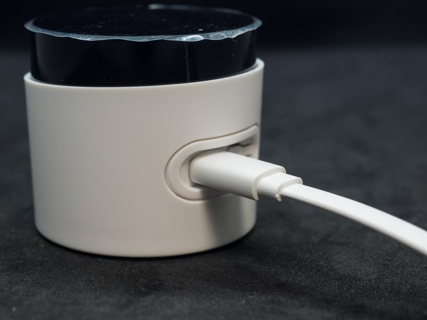
Индикатором активности служит светодиод, на противоположной от порта питания стороне. В режиме сопряжения он светит синим, в режиме обучения и отправки команд — желтым.
Broadlink
Приложение Intellectual Home Centre, которое у меня стояло ранее, отправило меня устанавливать обновленное приложение Broadlink. Еще раньше, помнится, использовалось приложение e-control. Ну да ладно. Переходим к добавлению нового устройства.
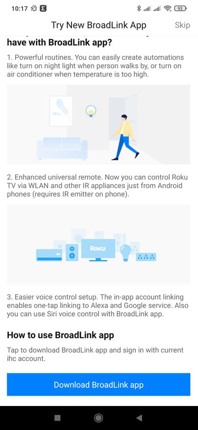
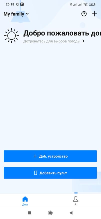
По умолчанию устройство находится в режиме точки доступа — его светодиод мигает не очень часто небольшими сериями. Для переключения в режим умной настройки, нужно удерживать нажатой кнопку возле разъема питания, пока светодиод не начнет мигать часто. Я подключил в режиме по умолчанию, для этого нужно найти новую сеть Broadlink wifi device.
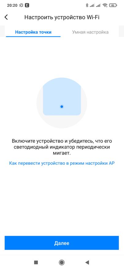
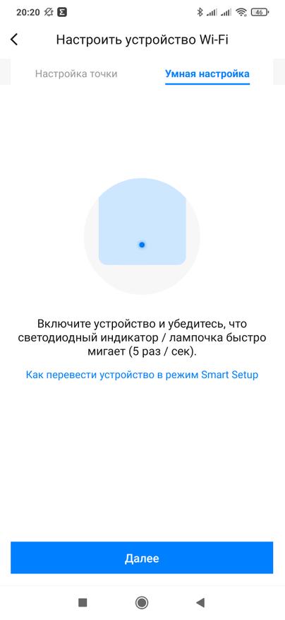
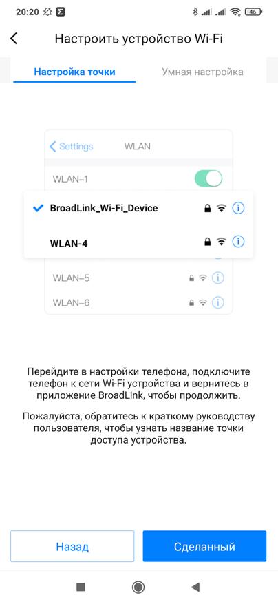
Действительно нашлась такая, без пароля. Подключаемся к ней, а при сообщении — что сеть не имеет подключения к Интернет — указываем, все равно использовать ее. Согласно указаниям мастера подключения, нужно временно отключить и мобильный доступ к сети.
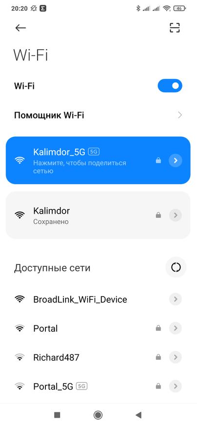
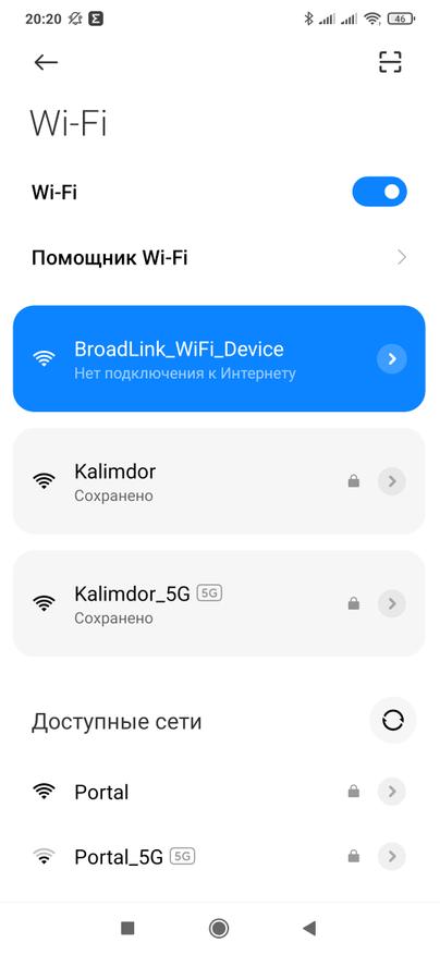
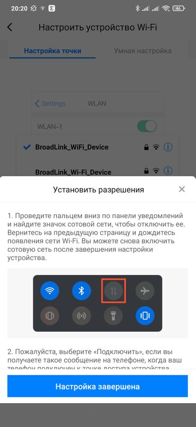
Далее указываем параметры своей домашней сети и ждем пока завершится процесс подключения.
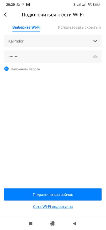
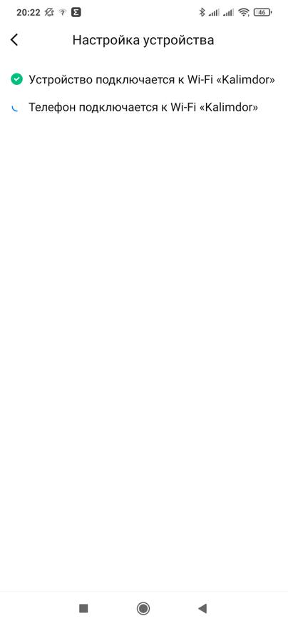
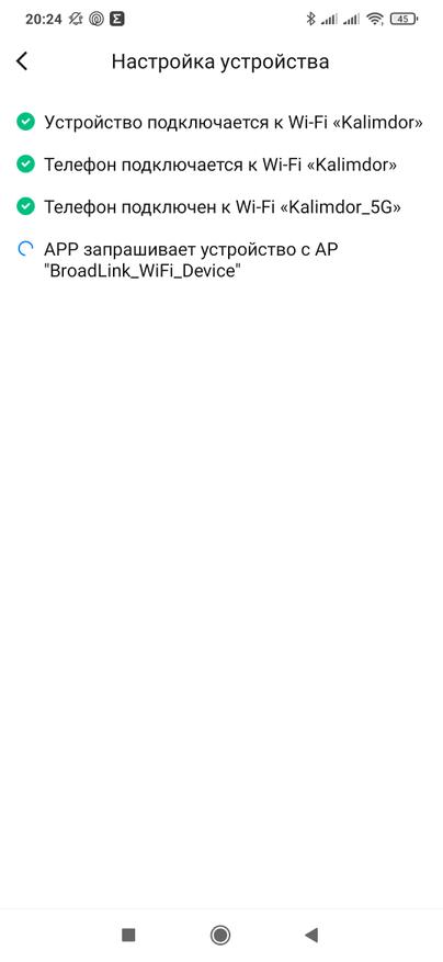
И в конце — необходимо указать комнату в которой будет находится пульт, а также можно изменить его название. Эти установки можно поменять в любой момент.
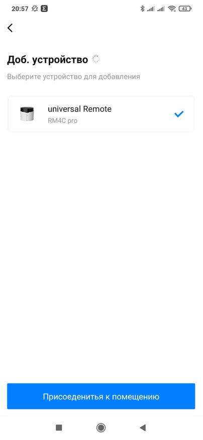
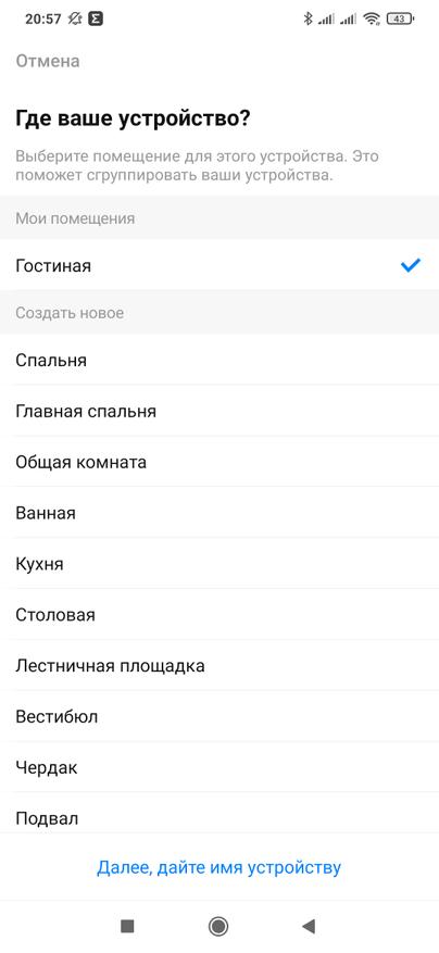
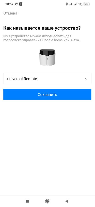
Теперь устройство добавлено в систему. Пока тут нет ни одного пульта, совсем скоро мы начнем разбираться с тем, как их сюда добавлять.
А пока зайдем в настройки — тут есть один очень важный переключатель, который отвечает за видимость устройства в локальной сети. Для интеграции в Home Assistant — его обязательно нужно отключить. Также стоит проверить версию прошивки.
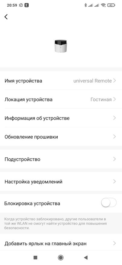
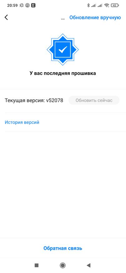
Добавление пультов
Перейдем к добавлению пультов для управления устройствами. Выбираем соответствующий пункт меню, далее — ИК и РФ устройства и, наконец выбираем героя обзора.
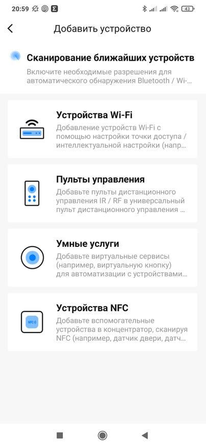
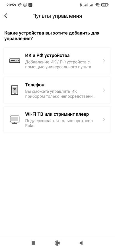
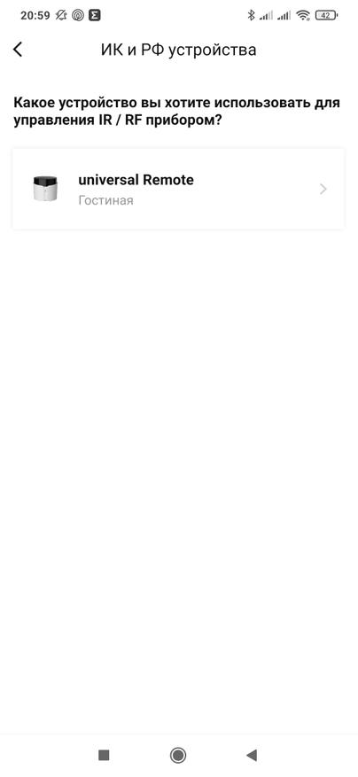
Теперь у нас появилось большое меню с различными классами устройств, а также с возможностью обучения с существующего пульта. Для начала добавим телевизор. В первом окне, мастер подключения просит проверить, что телевизор управляется не с bluetooth пульта
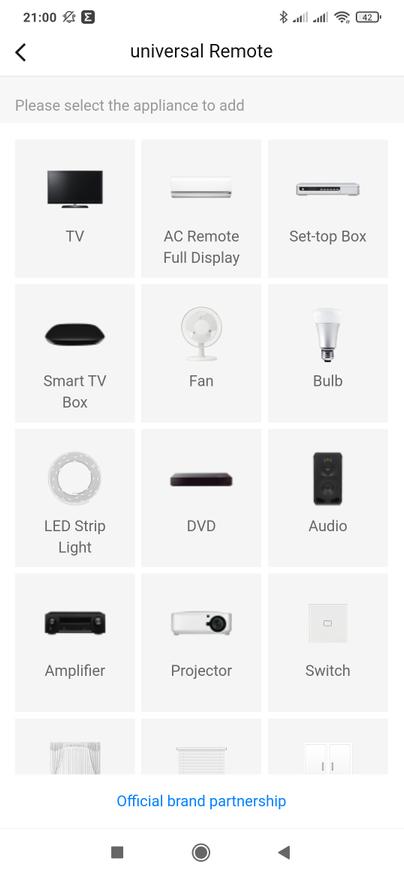
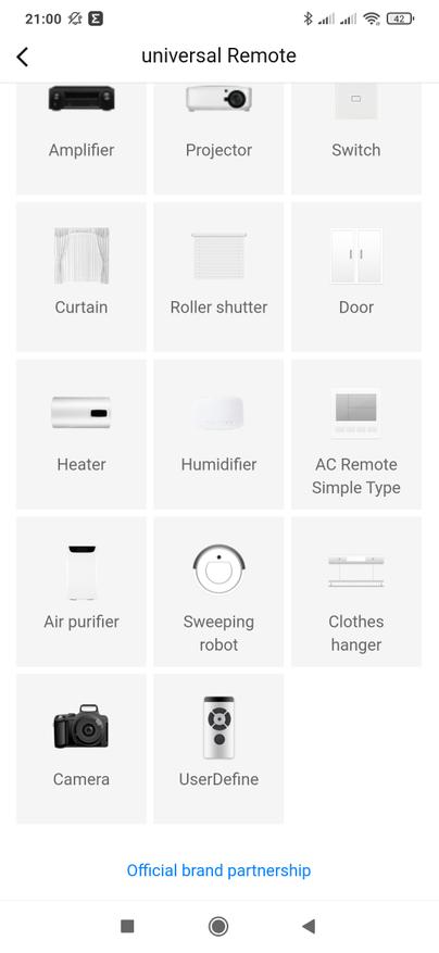
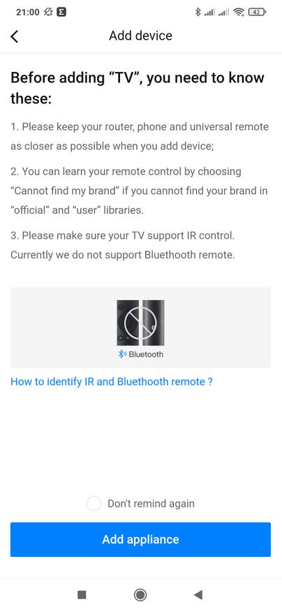
Мой телевизор Xiaomi Mi4 — хотя и комплектуется как раз bluetooth пультом с микрофоном, но при этом прекрасно управляется по ИК каналу. Первая же предложенная схема заработала — телевизор включался, корректно регулировал громкость. Нажимаем внизу на кнопку — работает хорошо и пульт добавляется в систему.
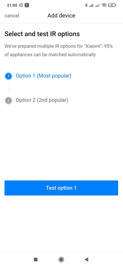
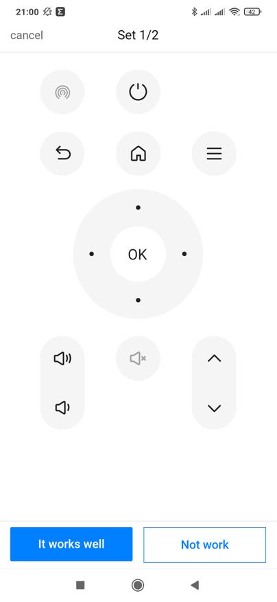
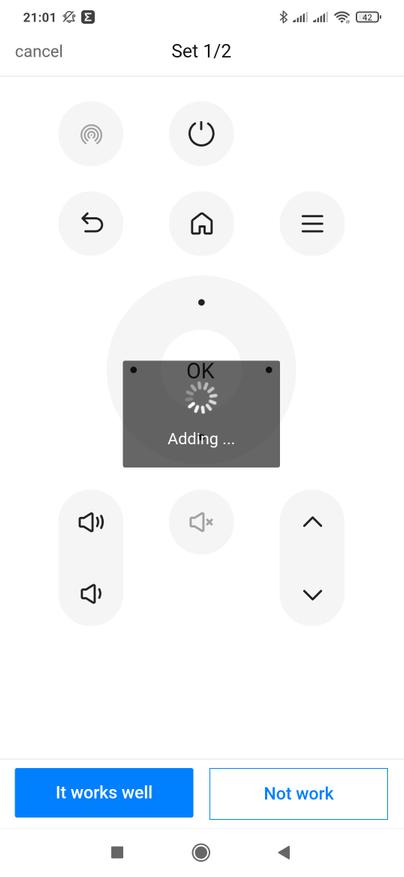
Остается указать локацию для устройства и название — теперь у нас есть один пульт и одна новая строка в общем списке.
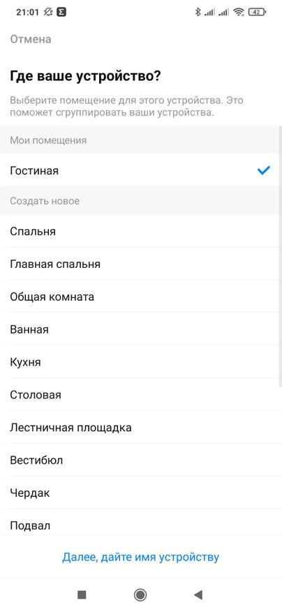
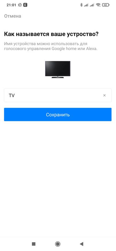
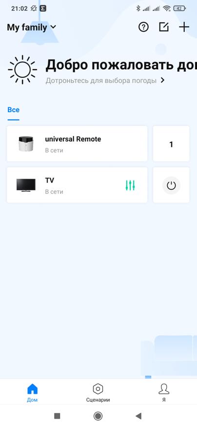
Теперь перейдем к кондиционерам. Тут тоже есть предупреждение — что в этой категории можно подключать пульты с экраном на котором отображается полная информация о состоянии, которые отправляют одной командой сразу все настройки — температуру, режим, скорость вентилятора и т.п. Для других — есть отдельная категория. Мой кондиционер попадает под Full State. Далее выбираем производителя и тестируем предложенные схемы.
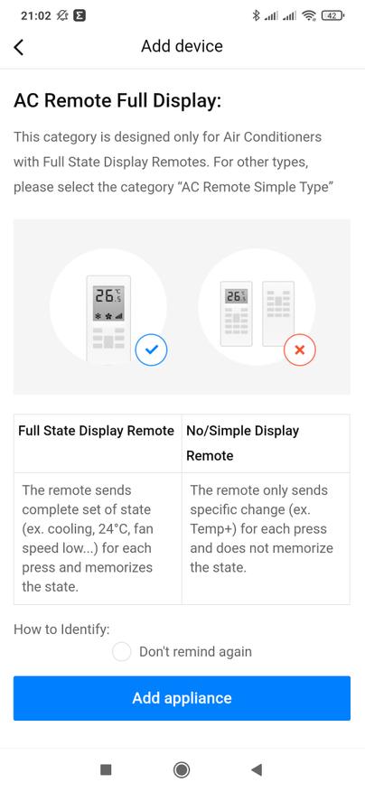
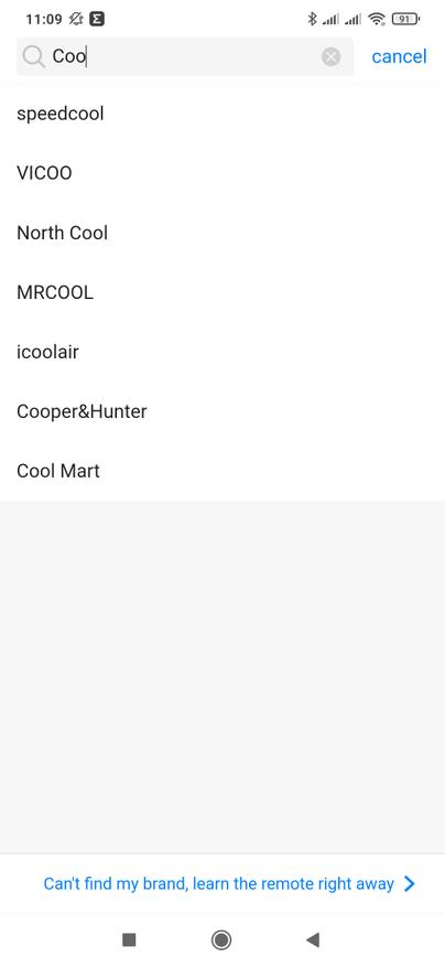
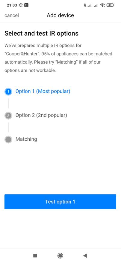
Проверяем реакцию кондиционера на экранные кнопки — у меня он завелся на первой же схеме, подтверждаем выбор аналогично как мы это делали с телевизором. Теперь в списке уже два устройства, которые изначально не предполагались для управления умным домом.
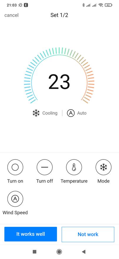
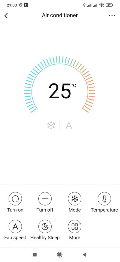
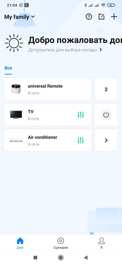
Добавим обучаемый пульт, для устройства которое не находится в предложенных категориях или производителях. Изначально добавляется просто пустой пульт, в который необходимо будет добавить кнопки.
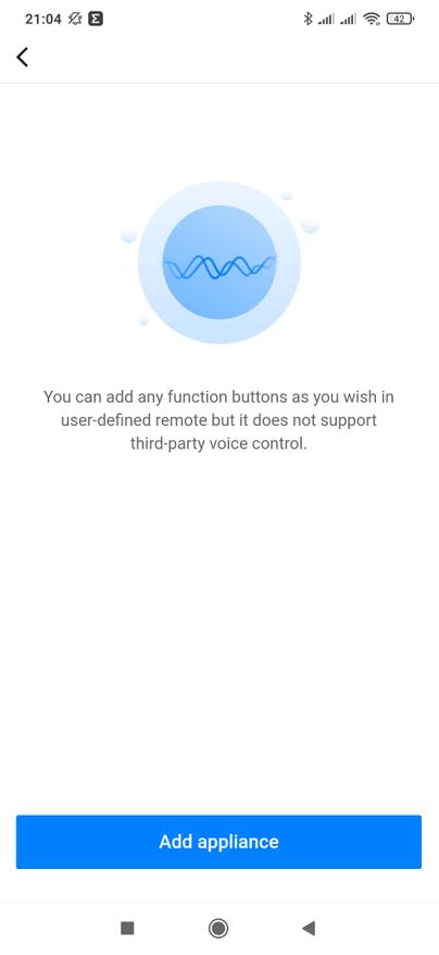
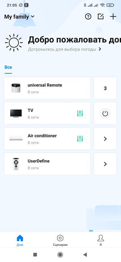
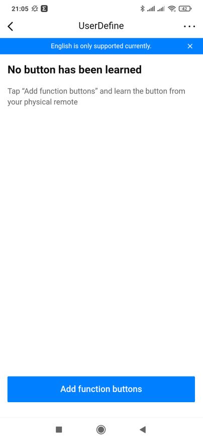
Далее предлагается выбрать тип пульта и его интерфейс — ИК или радио. Для начала обучим командам с ИК пульта. Тут все довольно просто, включаем режим обучения, направляем пульт-донор в сторону нашего героя и нажимаем, не удерживая, нужную кнопку. После этого можно проверить корректность отправки считанной команды.

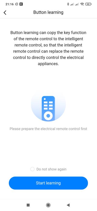
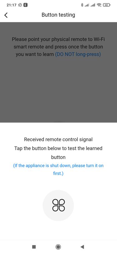
Если устройство корректно отработало полученную с универсального пульта команду, подтверждаем это и затем выбираем подходящую иконку и названию для новой кнопки. Для всех последующих команд на этот пульт — его тип уже указывать не надо. Таким образом обучаем всем необходимым командам, которые сможем теперь повторять.
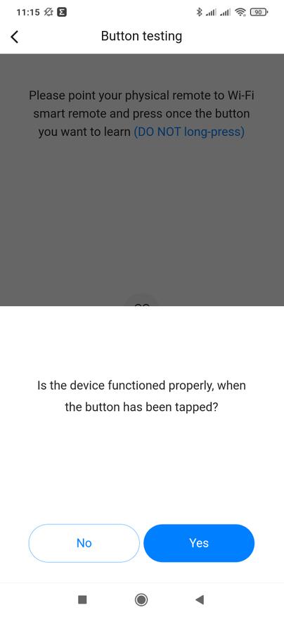
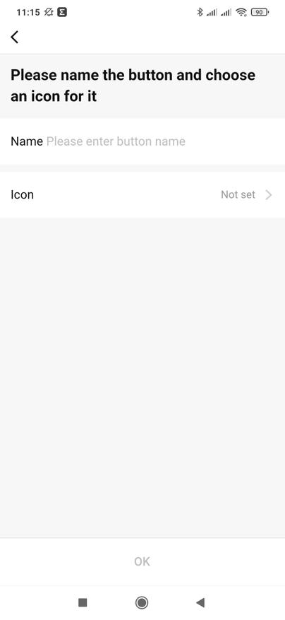

Теперь разберемся с радиопультами. Создаем новый обучаемый пульт и в меню выбора интерфейса указываем радио. Далее запускаем режим обучения и тут у нас есть две опции — исходный пульт есть в наличии или нет.
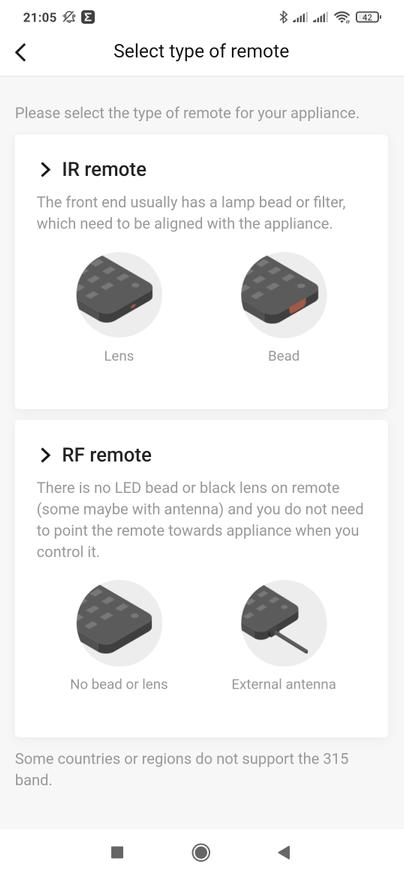
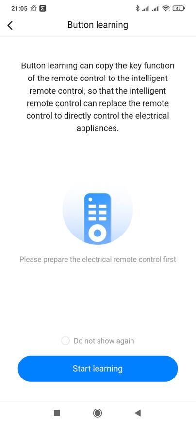
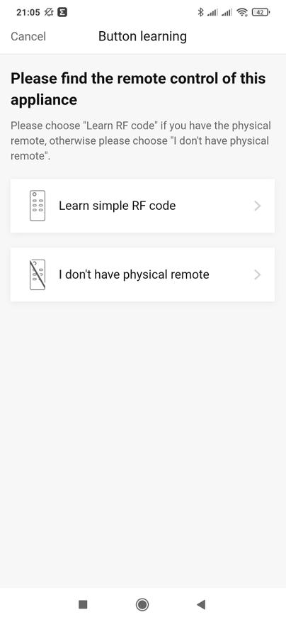
Если выбрать что пульта в наличии нет, то далее нужно будет подобрать вручную, либо найти в инструкции, на какой частоте работает управляемое устройство и попробовать спарить с ним универсальный пульт. Насколько я понимаю — он будет перебирать пока устройство не отреагирует на него.
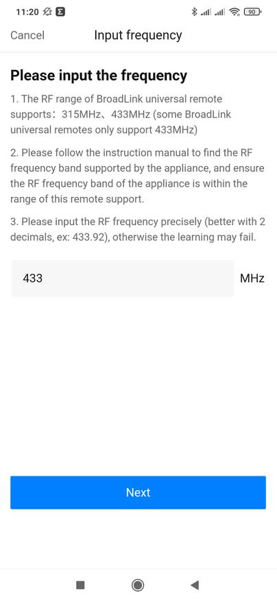
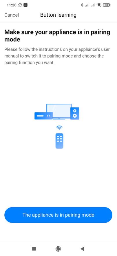
Все проще когда у вас все-же пульт есть. Тогда не надо угадывать частоту его работы, а запустить — ссылка внизу под кнопкой, режим сканирования частоты. При этом надо нажать и удерживать любую из кнопок пульта — донора, пока герой обзора не определит и покажет его частоту.
Далее все аналогично ИК командам. Указываем найденную частоту, уже без удержания — коротким нажатием обучаем команде, тестируем реакцию устройства, выбираем имя и иконку.

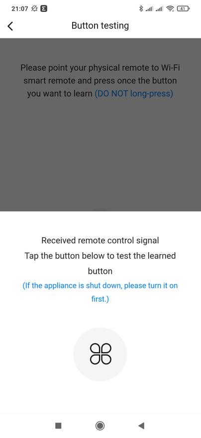
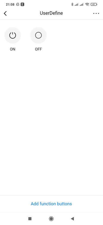
Автоматизации
В базовом приложении есть и автоматизации. Других устройств этой экосистемы у меня сюда не добавлено, поэтому смогу поэкспериментировать только с этим пультом. Логика тут привычная — есть триггер — то что вызывает сработку автоматизации, действие — то что автоматизация делает, и при необходимости — условие, это дополнительные параметры при соответствии которым автоматизация будет работать.
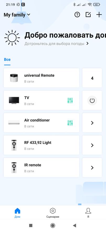
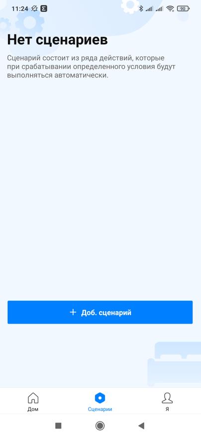
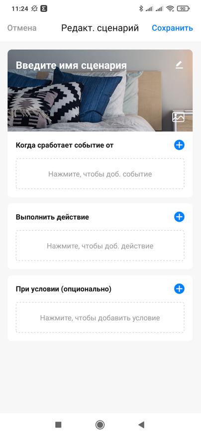
Вот вариант включения охлаждения кондиционера по заданному времени — в 6 часов вечера в будние дни. Например чтобы возвращаясь домой с работы — воздух уже был прохладным.
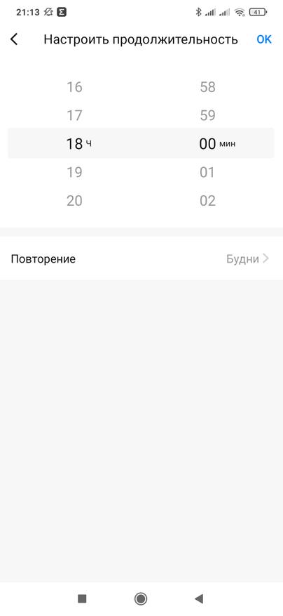
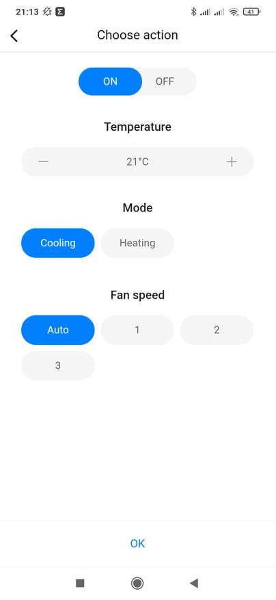
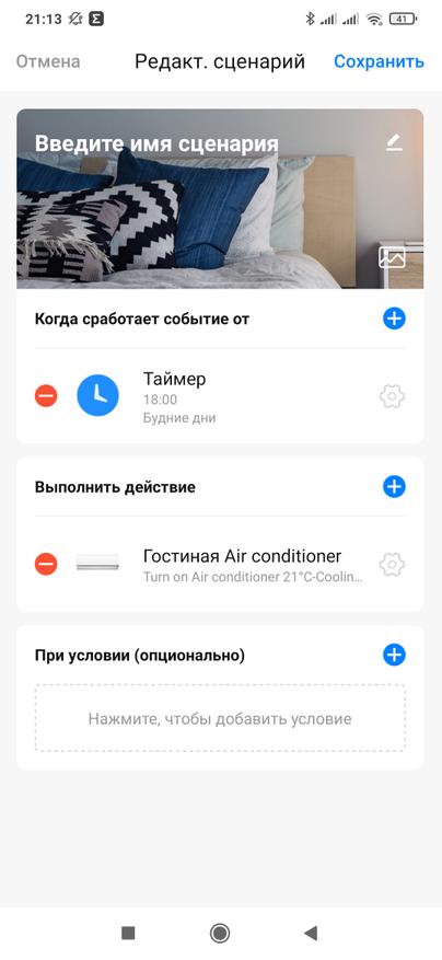
И нечто подобное — включение телевизора, вместо него может быть например музыкальный центр, по утрам, что-то вроде будильника который сложно проигнорировать.

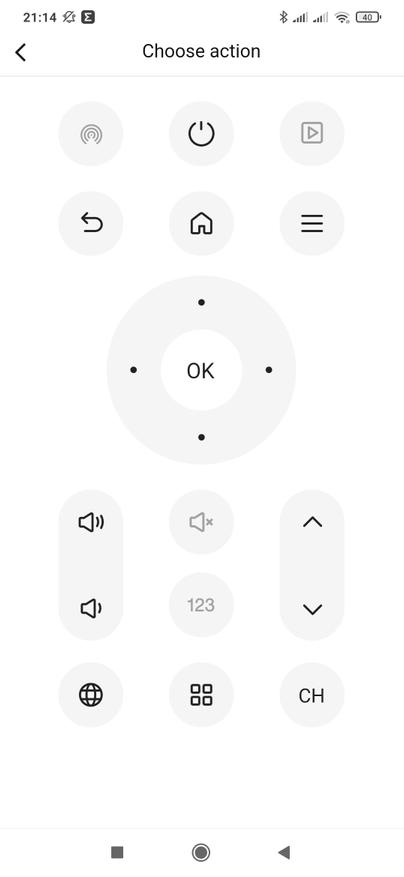
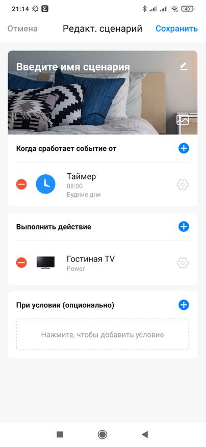
Google Home
Так как на коробке была указана совместимость с Google Assistant — я решил проверить и это. Взаимодействие построено стандартно — на уровне подключения аккаунта, который перебрасывает в Дом те устройства, которые могут с ним взаимодействовать. В этой случае — пульт телевизора и кондиционера. Добавленные и обученные вручную — не пробросились.
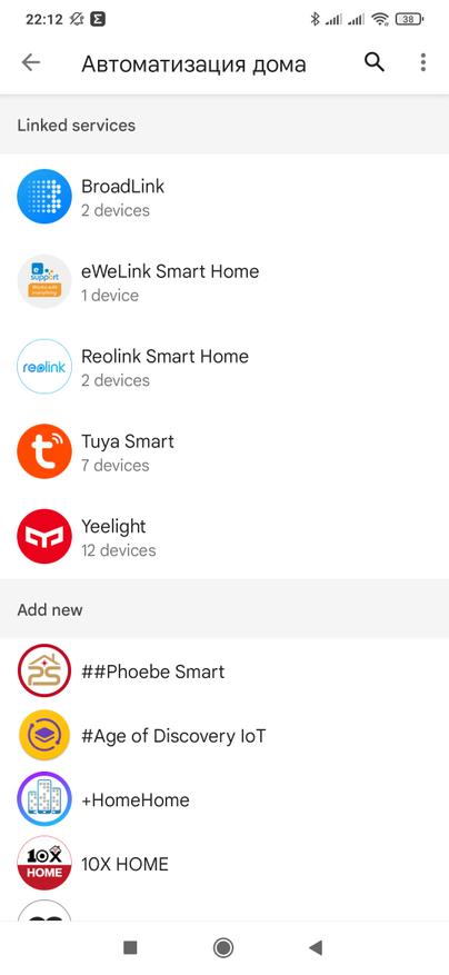
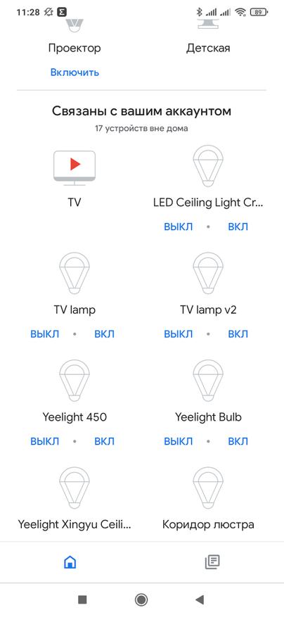
Ручное управление тут очень лаконичное — только включить и выключить, как для телевизора, так и для кондиционера, который будет активироваться в последнем настроенном режиме. А вот голосом — можно попросить Ассистента убавить пару градусов, добавить звук или переключить канал.
Home Assistant
Теперь перейдем к работе устройства в Home Assistant. Для этого нам понадобится выяснить его IP адрес и очень желательно закрепить его, чтобы при очередной перезагрузке роутера или его обновлении — он не поменялся.
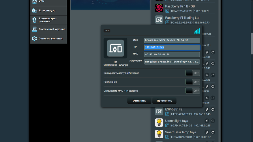
Через меню настройки — интеграции, ищем ту, что называется Broadlink, она штатная, отдельно добавлять не нужно.
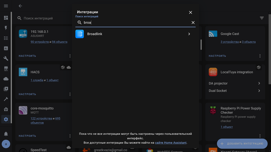
В следующем окне — необходимо ввести IP адрес подключаемого устройства, поэтому я и сказал о необходимости его закрепления на роутере.
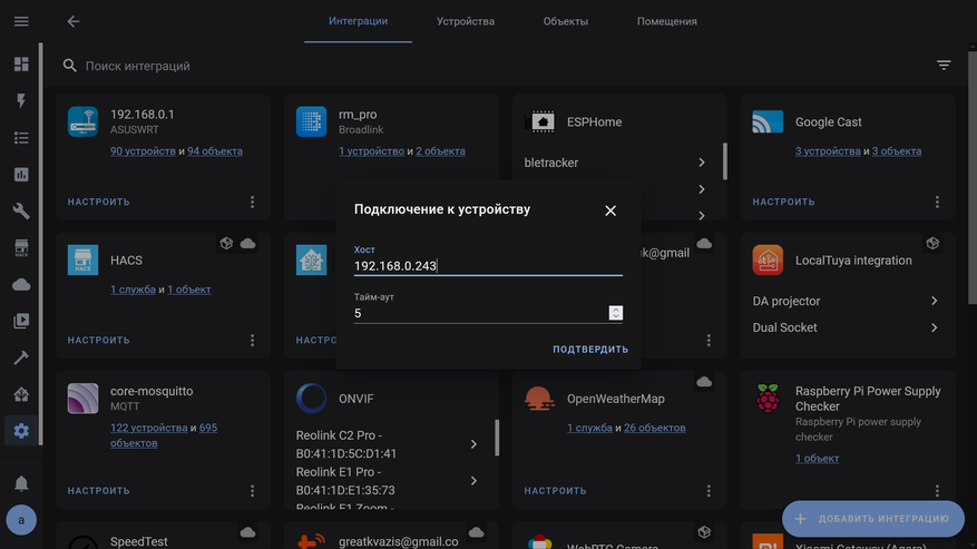
По состоянию на дату этого видео, интеграция Broadlink не поддерживает RM4C Pro. В следующем разделе мы добавим эту поддержку вручную, если у вас устройство добавилось нормально, то эту процедуру вы можете смело пропустить.
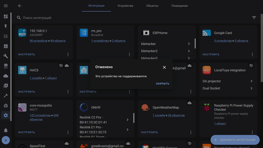
Для того чтобы начать что-то делать, нужно сначала выяснить все подробности — в журнале Home Assistant видим запись, что устройство 0х6184 — не поддерживается интеграцией Broadlink.
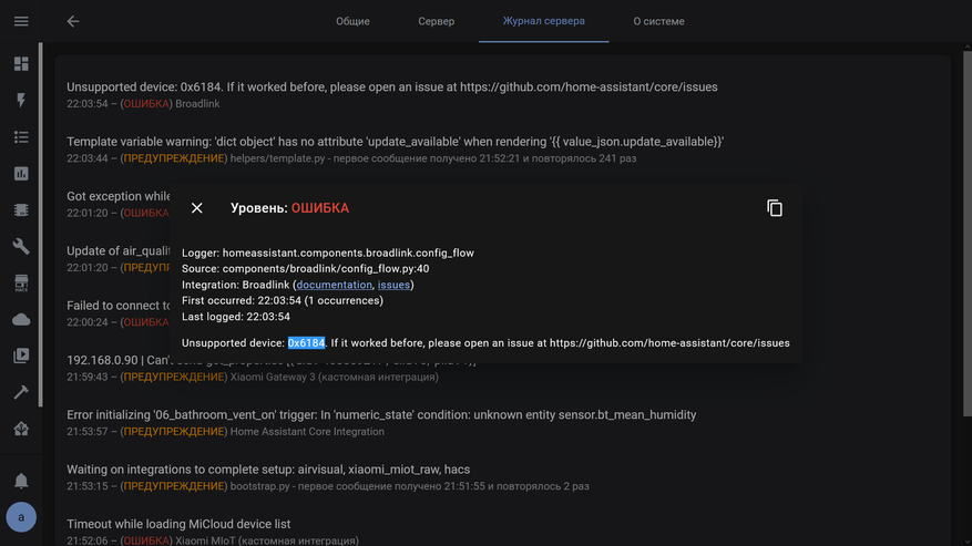
Не буду утомлять вас историей своих поисков и экспериментов, скажу лишь что необходимые запросы на добавление уже открыты. А мы перейдем к практической части — как сделать так, неподдерживаемая модель заработала в Home Assistant
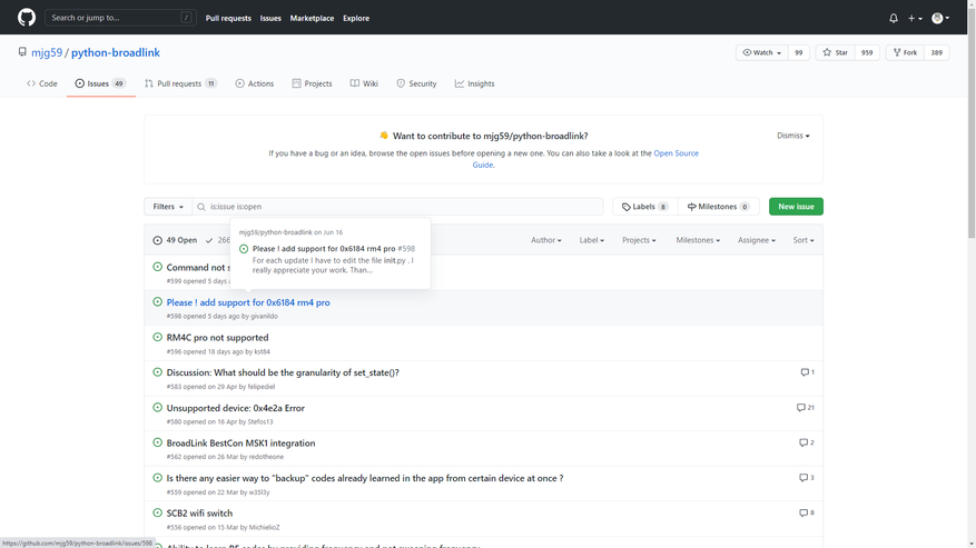
Добавляем поддержку
Сразу опишу готовый рецепт — нам необходимо зайти по SSH на консоль сервера c Home Assistant, тут показана версия с Raspbian и Supervised установкой. И забраться в внутренности контейнера home assistant. Все команды и примеры вы найдете по по этой ссылке.
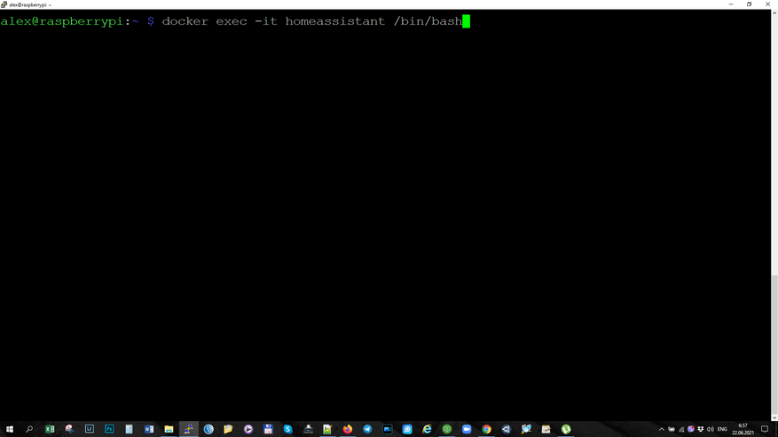
Внутри контейнера нам нужно перейти в папку с файлами штатной интеграции broadlink
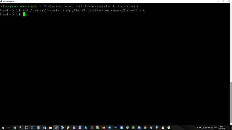
Вывод списка файлов — не обязателен для решения нашей задачи, просто для иллюстрации. Нам нужен файл init
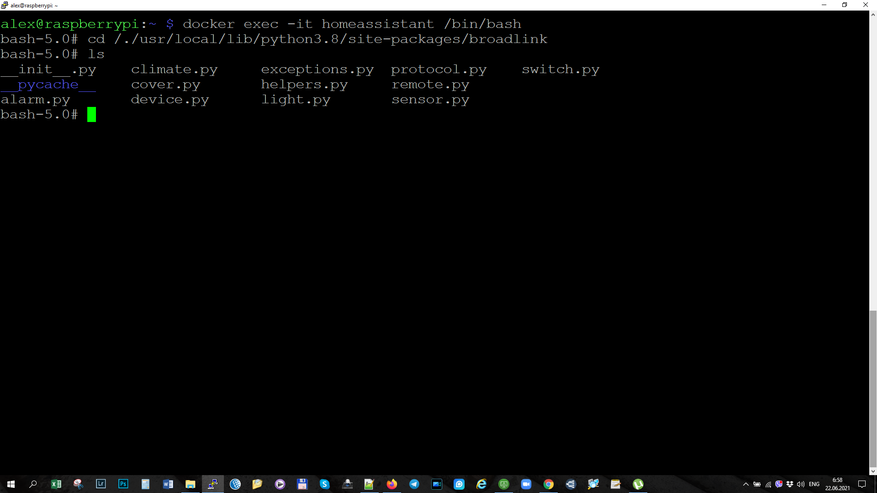
Открываем его при помощи редактора для настоящих Unix админов — vi. С каждой минутой работы в нем — вы будете чувствовать как у вас отрастает борода и свитер.
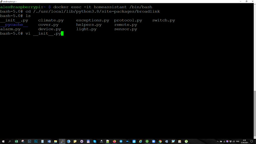
Вся задача сводится к добавлению еще одной строки в перечень поддерживаемого оборудования. Так как все остальное для героя обзора — стандартно.
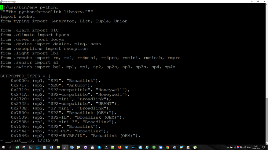
Для перехода в режим редактирования надо нажать клавишу i. После этого из приложенного мной текстового файла — копируем строку устройства 0х6184 и вставляем ее в этот файл при помощи правой клавиши мыши. Проверяем корректность, выравниваем.
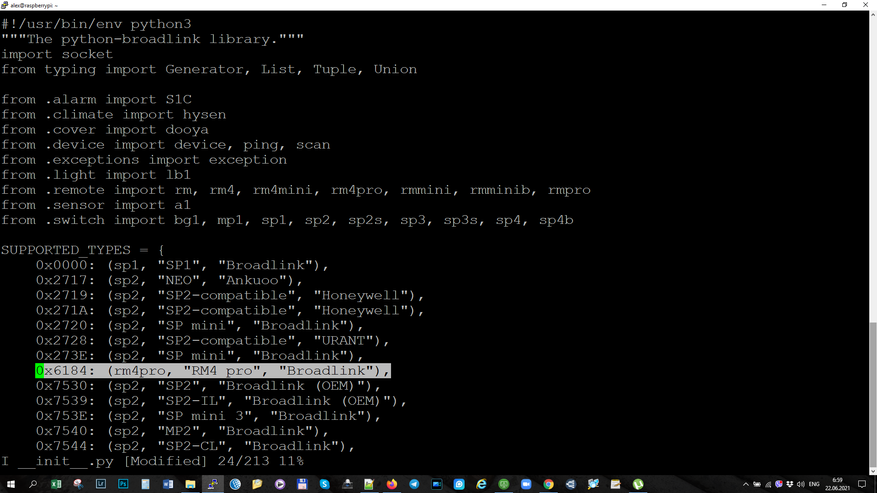
Для выхода из режима редактирования нажимаем Esc, а для сохранения изменений — двоеточие и w.
Для выхода из редактора — двоеточие, q и восклицательный знак. Вот так настоящие админы редактируют свои конфиги.
Для выхода из контейнера — набираем команду exit. После этого нужно перезагрузить Home Assistant. Есть один момент — после каждого обновления Home Assistant, эту процедуру придется обновлять до тех пор, пока не будет добавлена штатная поддержка.
Подключение
Возвращаемся к подключению устройства, теперь его поддержка есть в системе, повторюсь что предыдущий шаг — временный, пока эту поддержку не сделают штатной.
Интеграция предложила сложно читаемое имя написанное иероглифами. Меняем, по своему усмотрению, на более осмысленное и понятное.
Запись для устройства добавлена, при необходимости можем указать для него помещение.
Добавленный гаджет относится к домену remote, когда для Broadlink использовались свои специфические службы, теперь они стандартизированы.
Обучение командам
Приступим к обучению командам, для этого я буду использовать скрипты. Напомню что все рассмотренные примеры есть в текстовом виде в приложенном файле.
Для обучения используется специальная служба remote learn.
Далее указываем какое устройство будет обучаться команде.
Следующие настройки задают описание обучаемой команде — имя устройство, указываем как хотим, например tv
И название команды — например power. Сохраняем, перегружаем и запускаем скрипт
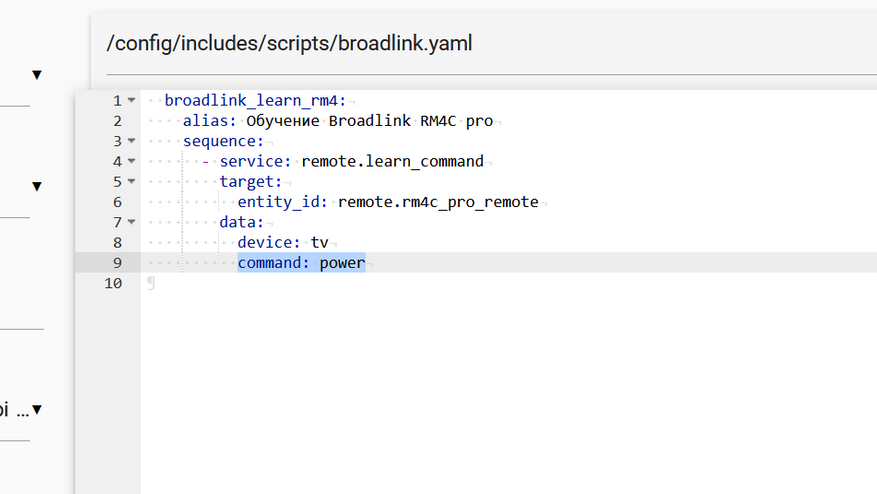
На универсальном пульте на 30 секунд загорается желтый светодиод, в меню уведомлений приходит сообщение о том, что нужно нажать указанную клавишу на пульте — доноре. После нажатия — светодиод гаснет, команда сохранена.
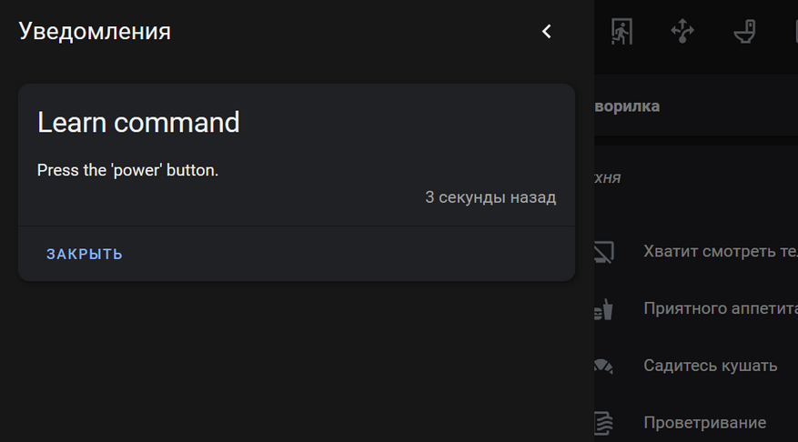
Давайте выясним где она физически хранится. Для доступа к ней при помощи штатного редактора File Editor, нам, через меню Supervisor нужно зайти в его конфигурацию, и найти папку storage в списке игнорируемых.
Убираем ее, сохраняем, после чего аддон перезагружается.
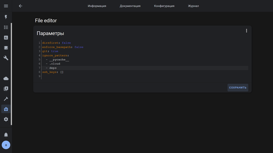
Теперь в папке config у нас отображается ранее скрытая папка storage в которой ищем файл который называется на broadlink remote.
В нем и видим информацию о устройстве, команде и сохраненный код в виде набора символов. Этим набором, кстати можно делится с другими владельцами пультов broadlink — как отправлять команды в виде сырого кода, я покажу далее.
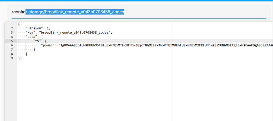
Аналогично добавляем и другие клавиши — например повышение уровня громкости. Новый код добавится к этому устройству. Обратите внимание, что ИК коды имеют одинаковый набор символов в начале команды.
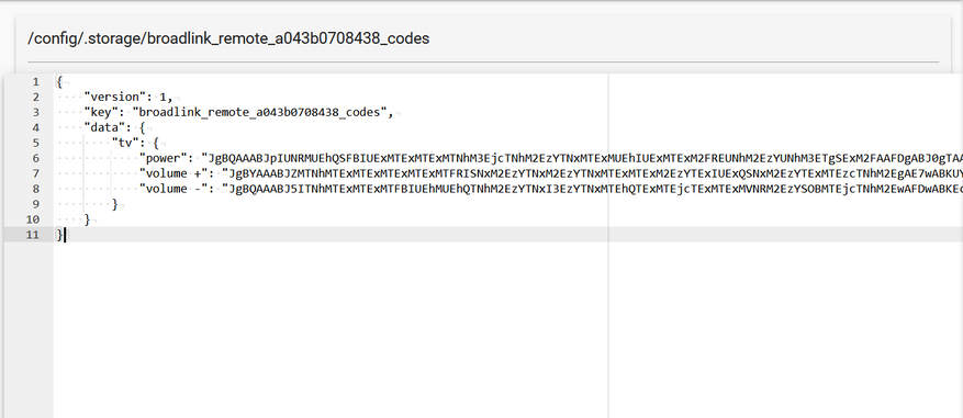
Теперь добавим код с радиопульта. Основной синтаксис тут такой же, служба remote learn, указываем название устройства, команды, но в конце добавляем ее тип — rf
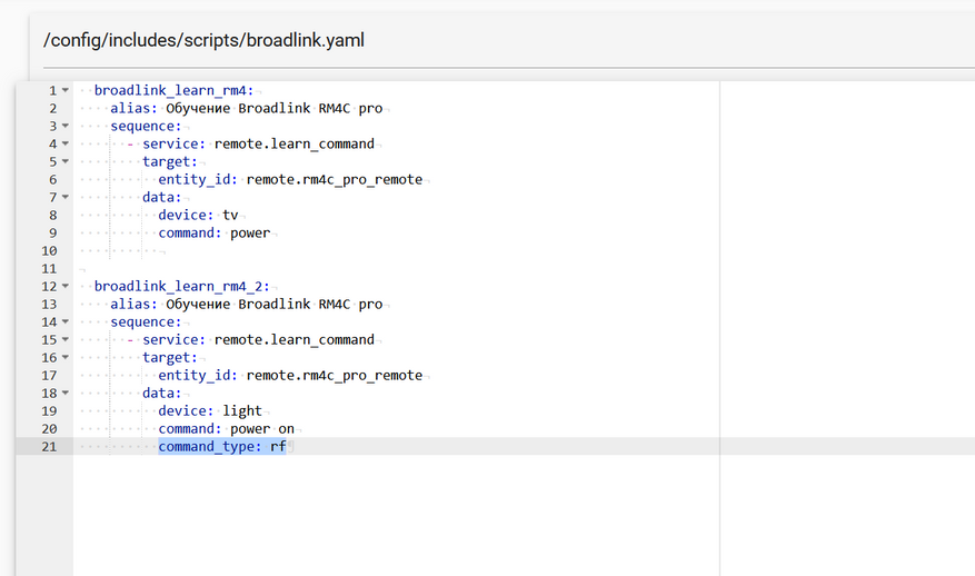
Тут обучение происходит в два этапа — сначала сканирование, на broadlink загорается желтый диод, на пульте доноре нажимаем и удерживаем кнопку. В течении секунд 30 — база определяет частоту, диод гаснет — отпускаем кнопку.
Диод загорается снова, на пульте теперь коротко нажимаем и отпускаем кнопку, команде с которой хотим обучить .
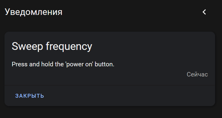
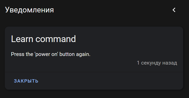
В файле появляется новое устройство и команда. Обратите внимание что ее код кардинально отличается от ИК команд. Именно символы в начале и позволяют понять базе — как отправлять этот код, по ИК или радиоканалу.
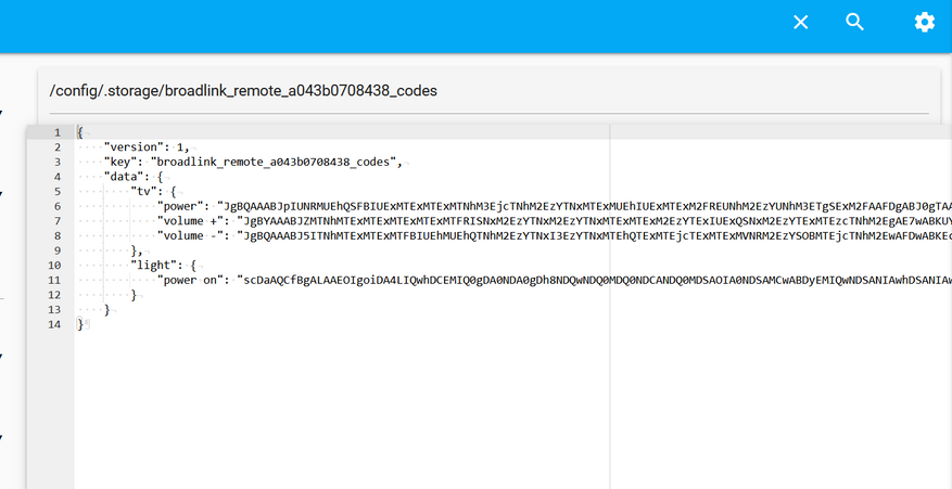
Конечно если нужно обучить нескольким командам с одного пульта — удобнее сделать это за один раз. В таком случае в скрипте просто перечисляем названия тех команды которые мы хотим сохранить.
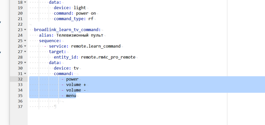
Далее, просто следуем за подсказками в уведомлениях, нажимая поочередно все команды из перечня.
Вот все команды сохранены в той очередности в которой мы указали в скрипте. При повторном обучении — старая команда заменяется новой.
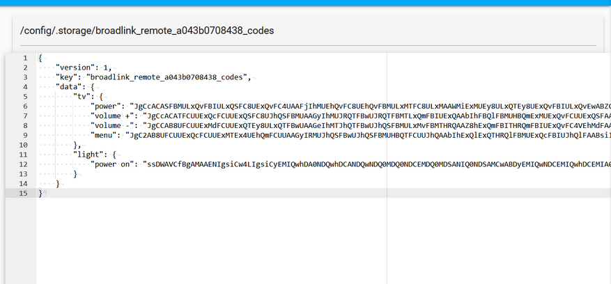
Отправка команд
Логика отправки команд подобна обучению. Для этого используется сервис remote send и указываем с какого устройства слать.
Далее — указываем устройство и название команды, пишем тоже что и при обучении. Данные берутся с уже рассмотренного нами файла.
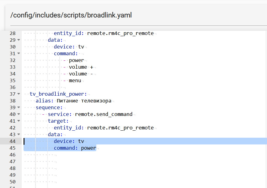
Если команду нужно повторить несколько раз, например актуально для громкости, указываем число повторов в параметре repeat.
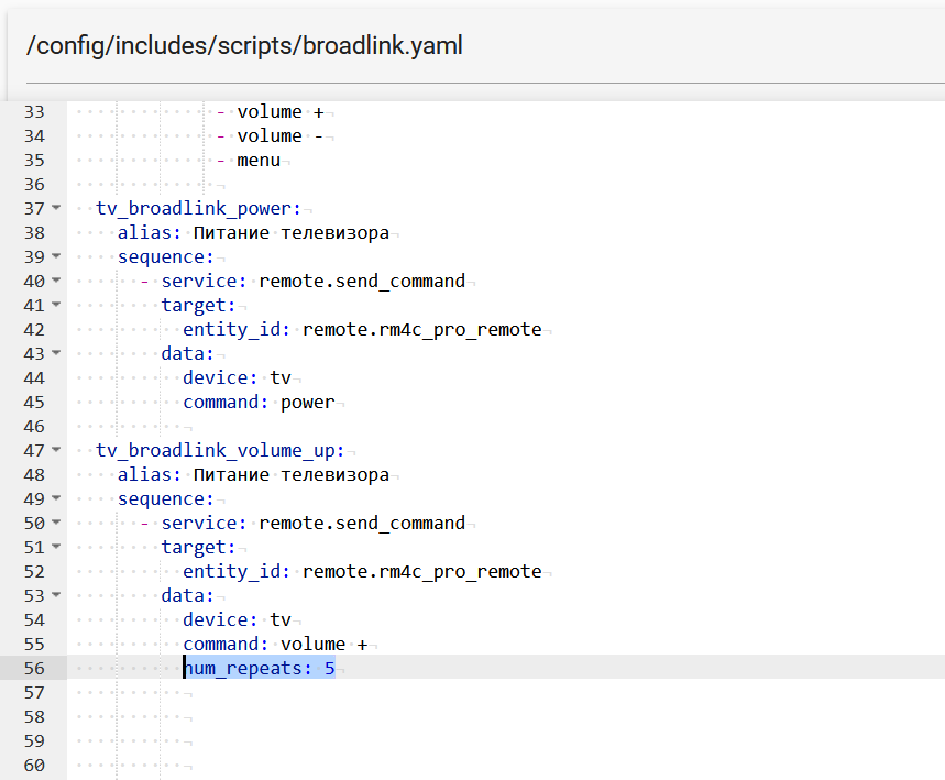
Можно и просто задать список команд… Это удобно для кейсов, где нужно повторять одну и ту же последовательность, которую можно забить например на одну кнопку.
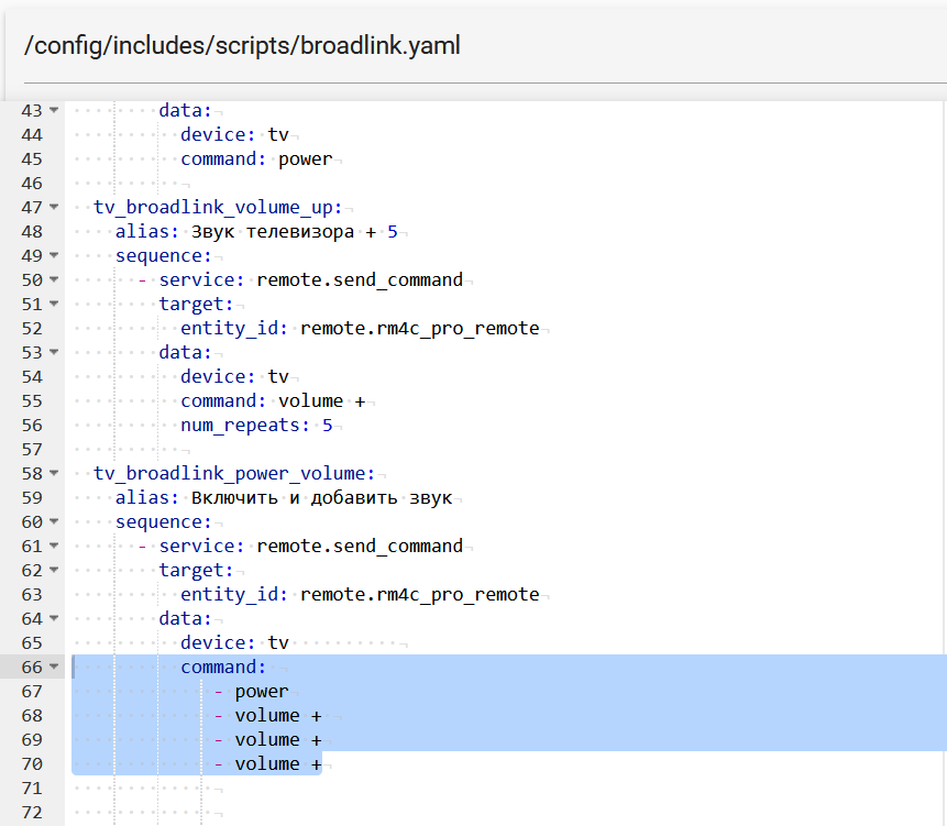
Как я упоминал вначале — команды можно отправлять с сыром виде, копируя код, указанный в кавычках, в файле storage. В начале такой команды нужно указать префикс b64.
Для такого формата работает и последовательность команд. Еще раз уточню, что выучить команду вы можете на одном пульте broadlink — причем даже другой модели, а воспроизвести на другом. Это позволяет даже передавать свои команды другим пользователям аналогичных устройств.
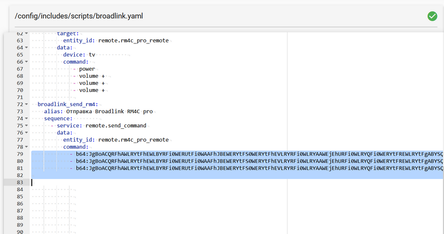
Удаление команд
Если вы по какой-то причине захотите удалить сохраненную команду, вручную это сделать не удастся, она все равно появится в файле, да и можно случайно прихватить лишнее. Лучше использовать специальный сервис — remote delete,
и пульт — чтобы система знала в каком файле ее искать
Далее, как и при обучении и отправке, указываем из какого устройства и какую команду удалять.
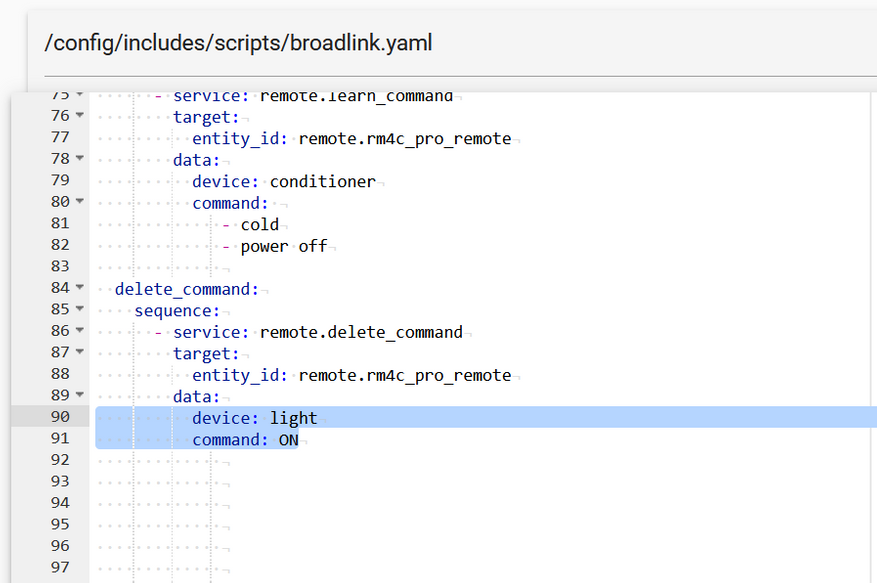
Кондиционер
В качестве практики приведу кейс управления кондиционером. В моем случае, при нажатии любой кнопки — пульт передает сразу все параметры — температуру, скорость, режим и так далее. Поэтому, я заранее настроил нужный мне режим работы и теперь мне нужно выучить всего два кода, причем с одной кнопки on off. В одном случае на устройство передаются полностью все настройки работы, во втором — команда на выключение.
Создаю скрипт для обучения, в котором перечисляю команды — охлаждение и выключение для устройства кондиционер.
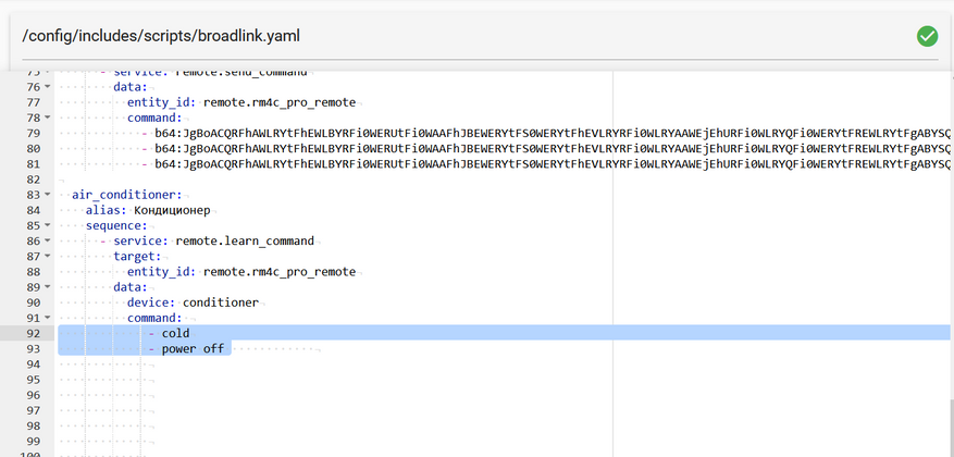
Обучаю пульт и проверяю что в файле появились две строки — одна команда для включения режима охлаждения с заданными параметрами, вторая — для выключения.
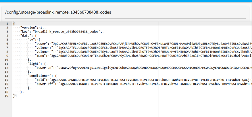
Создам для удобства отдельный пакадж, его вы тоже найдете в приложенном файле, тут создам раздел switch, буду использовать платформу шаблонов
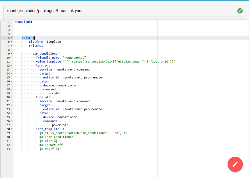
Для получения обратной связи от кондиционера я буду использовать счетчик потребления питания, если мощность более 10 ватт — значит он включен. Как вариант — можно использовать установленный на закрылках геркон.
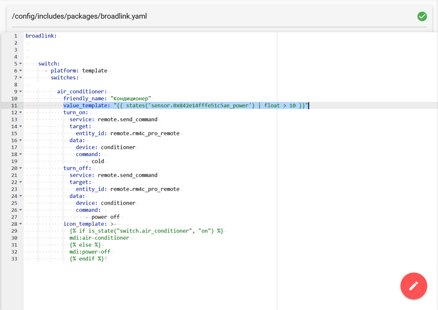
При включении этого свича, будет срабатывать сервис отправки команды кондиционеру на охлаждение.
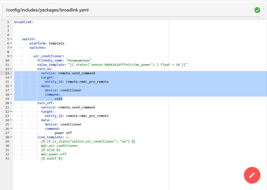
Соответственно при выключении — команда которая отключает кондиционер. Все довольно просто.
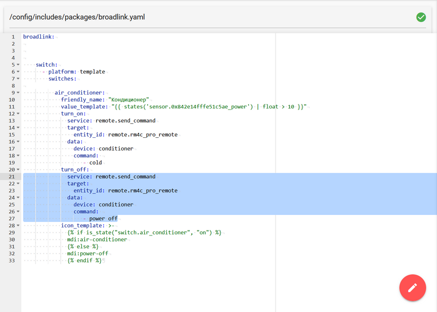
При желании, это необязательно, можно украсить свич иконкой, которая будет менять свой вид, в зависимости от его статуса.
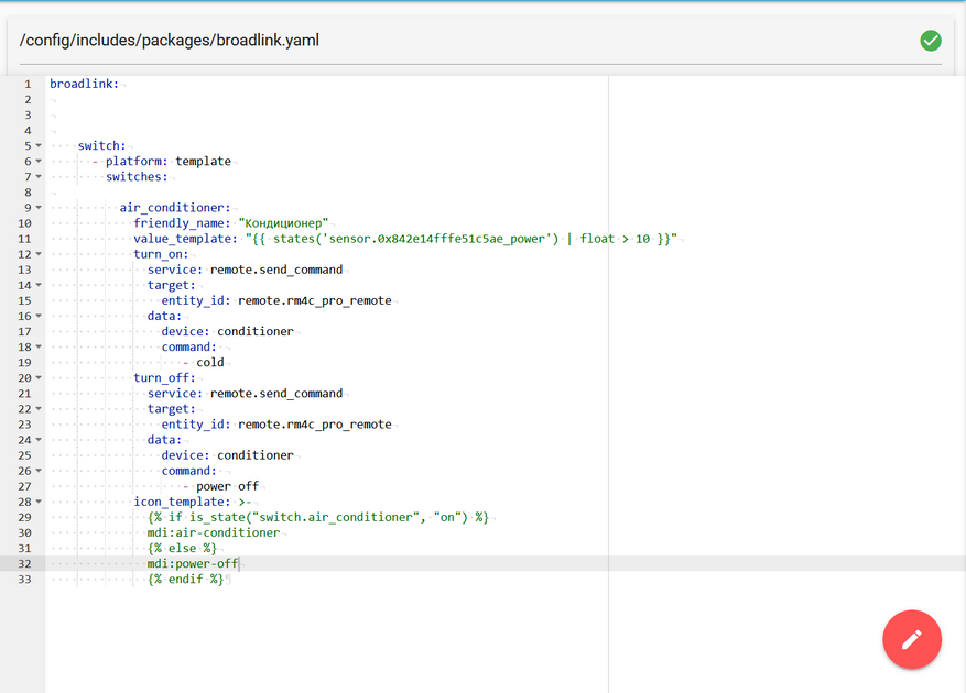
Имея свич, который управляет кондиционером — можно сделать и сущность climate
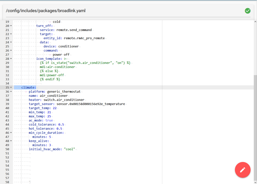
Это термостат, который будет поддерживать заданную температуру в комнате и управлять кондиционером.

Указываем созданный нами шаблонный свич
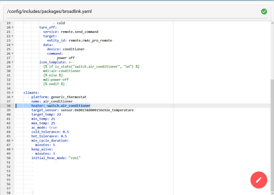
Сенсор температуры, на показания которого будет ориентироваться созданная нами сущность, затем целевую температуру — которую он будет поддерживать, максимальную и минимальную температуры для ползунка
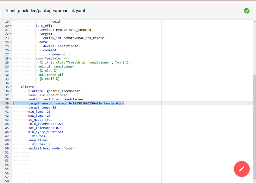
А в этом разделе устанавливаем значение true — тогда термостат, по умолчанию настроенный на нагрев, будет заниматься охлаждением. Указываем значения температурного коридора — в примере полградуса вверх и вниз от целевой температуры.
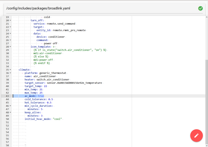
Режим инициализации — охлаждение. Можно поставит выключено, как нужно для вашего кейса.
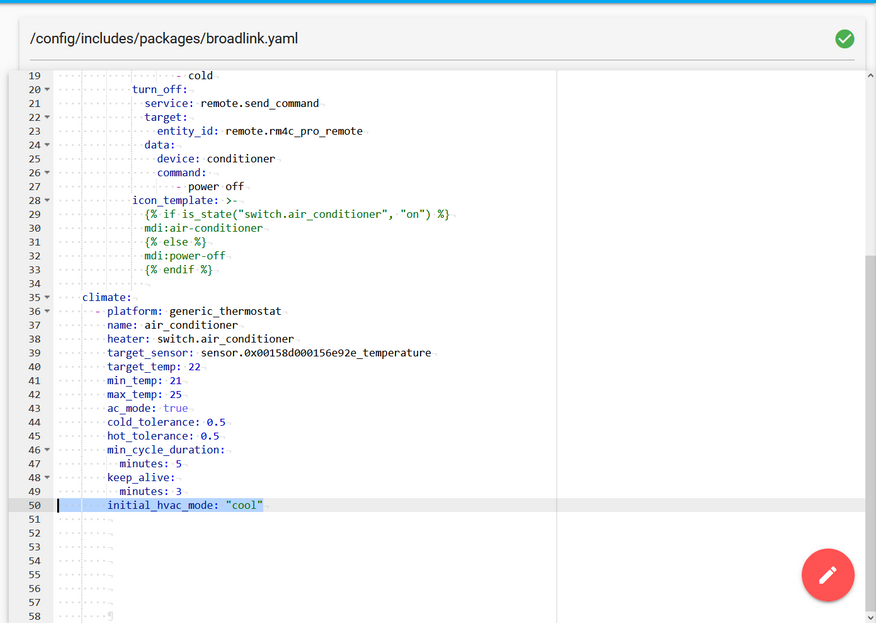
А так будет выглядеть эта сущность при визуализации стандартной картой lovelace — термостат. Полностью в автоматическом режиме она будет включать кондиционер при достижении верхней границы температурного коридора, и выключать при достижении нижней.
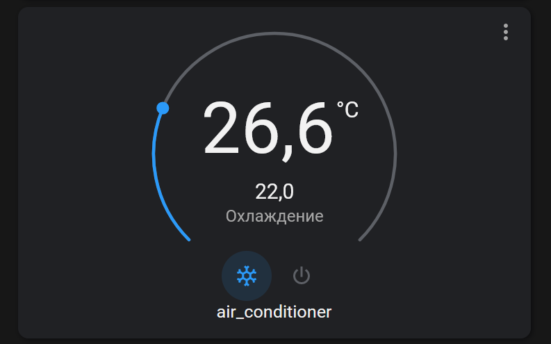
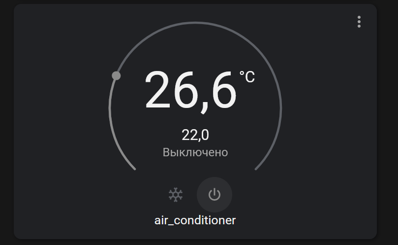
Обычно подобные кейса имеют обвес из дополнительных автоматизаций — которые, например будут отключать термостат и кондиционер в ночное время, при открытии окон, при обнаружении людей и так далее. Но это уже тема для отдельного обзора.
Видеоверсия обзора
Вывод
На этом все, сегодня у меня получился наполовину обзор, наполовину — очередной урок по работе с Home Assistant. Показанные примеры — актуальны для всех моделей ИК РФ контролеров Broadlink, ссылку на текстовый файл вы найдете в описании.
Досвидания, до новых встреч.

Робо-советник CADY WILE с интеллектуальным пультом дистанционного управления 2.4 ГГц

ВОЗРАСТ: 8+
* Пожалуйста, внимательно прочтите руководство пользователя перед работой и сохраните его в надлежащем месте для использования в будущем.
АКСЕССУАРЫ

Ноты:
Пожалуйста, внимательно проверьте количество аксессуаров (как показано выше).
Предоставьте подтверждение покупки и обратитесь в магазин для замены, если какие-либо детали отсутствуют.
Сборка и зарядка аккумулятора
1. Сборка аккумулятора для пульта дистанционного управления

Откройте крышку батарейного отсека, вставьте две батарейки AAA (не входят в комплект).
Ноты:
- Убедитесь, что символы полярности на батареях совпадают с символами внутри батарейного отсека.
- Не смешивайте новые и старые батареи.
- Не используйте одновременно батарейки разных типов.
2. Зарядка аккумулятора для робота.

Подключите USB-кабель для зарядки с роботом на одном конце и USB-интерфейсом для зарядки на другом конце.

Ноты:
Полная зарядка занимает около 55-70 минут, а время работы робота составляет около 60-80 минут после полной зарядки.
 Инструкции по использованию аккумулятора
- При использовании литиевой батареи существует определенный риск. Это может привести к пожару, телесным повреждениям или материальному ущербу. Пользователи должны осознавать риски и нести полную ответственность за неправильное использование батареи.
- В случае протечки батареи избегайте попадания электролита в глаза или на кожу. Как только это произойдет, промойте глаза чистой водой и немедленно обратитесь за медицинской помощью.
- Немедленно выньте вилку из розетки, если почувствуете странный запах, шум или смог.
Зарядка батареи
- Пожалуйста, используйте зарядное устройство от оригинального завода, чтобы обеспечить вашу безопасность.
- Не заряжайте дилатант или изношенную батарею.
- Не заряжайте аккумулятор слишком сильно. После полной зарядки отключите зарядное устройство.
- Не заряжайте аккумулятор рядом с легковоспламеняющимися материалами, такими как ковер, деревянный пол или деревянная мебель, или на поверхности электропроводящих предметов. Пожалуйста, всегда следите за аккумулятором во время зарядки.
- Не заряжайте еще не остывший аккумулятор.
- Температура зарядки должна быть от 0 ° C до 40 ° C.
Утилизация батарей
- Не выбрасывайте аккумулятор вместе с обычным мусором. Ознакомьтесь с местным методом утилизации мусора и утилизируйте его в соответствии с особыми требованиями.
ЗНАЙТЕ СВОЙ ПУЛЬТ ДИСТАНЦИОННОГО УПРАВЛЕНИЯ

- вперед
- назад
- Повернуть налево
- Поверните направо
- Монстр Beats
- суррогатного материнства
- Включение / выключение подсветки ушей
- Изменение цвета подсветки ушей
- Музыка
- Интерактивное управление звуком
- Оригинальный звук
- Послать подарки
- Start / Stop
- Отображение основного движения
- Volume +
- Объем-
- Танцевальные песни
- Запись
- Светодиодный индикатор
- Переключатель мощности света
УПРАВЛЯЙТЕ ВАШИМ РОБОТОМ
- Выключатель
Здравствуйте, меня зовут Робот Кэди Уайл. Я ваш личный финансовый советник. Вы найдете меня полезным и талантливым, потому что я могу не только хорошо петь и танцевать, но также рассказывать истории и играть музыку. Я готов предложить почти все, что вы ожидаете, и даже больше, например, отыграть чудовище, отправить подарки или выполнить поручения, если вам нужно. Я тебе понравлюсь. Я сначала покажу тебе танцевальное представление. Присоединяйтесь ко мне и танцуйте со мной. Музыка! - Резервный
Робот будет разговаривать с вами каждые 20 секунд в режиме ожидания.- Привет? Есть там кто-нибудь?
- Поиграй со мной!
- Давайте танцевать вместе.
- выключение
Система будет отключена. Увидимся в следующий раз. До свидания! - Отображение основного движения
Начало: Я собираюсь показать основные движения. Готов идти!
Стоп: Спектакль окончен! Присоединяйтесь ко мне и давайте играть вместе! - Сдвинуть вперед / назад

- Повернуть налево повернуть направо

- Запись
Нажмите кнопку «Запись», чтобы начать запись, и нажмите еще раз, чтобы закончить и воспроизвести. - Монстр Beats
Нажмите кнопку «Monster Beats», чтобы изменить содержимое записи тремя способами. - Start / Stop
Нажмите кнопку «Старт / Стоп», чтобы остановиться и перейти в режим ожидания. Нажмите еще раз, чтобы перезапустить - Громкость +/-
Есть пять уровней томов (дефектный объем на 3-м уровне). Увеличьте громкость звука во время голосовых подсказок. - Программа Нажмите кнопку «Программа», чтобы запустить программу (шесть кнопок для программирования движений, включая вперед, назад, поворот налево, поворот вправо, музыку, танцевальные песни и другие кнопки, чтобы остановить программу) и нажмите еще раз, чтобы отобразить запрограммированные движения. .
- Изменение цвета подсветки ушей
После включения робота его глазная подсветка RGB станет многоцветной и постепенно меняет цвета. После успешного сопряжения нажмите кнопку «Изменение цвета подсветки уха», чтобы изменить цвет подсветки уха. Нажмите один раз, чтобы изменить цвет подсветки уха с одного цвета на другой, и нажмите более двух раз, чтобы включить многоцветный свет и постепенно менять цвета. - Включение / выключение подсветки ушей
Когда робот запускается, в его ухе загорается лампочка. Коснитесь наушника, чтобы выключить его, и коснитесь еще раз, чтобы включить его. Пожалуйста, обратитесь к пункту 12 для получения дополнительной информации об изменении цвета подсветки уха. - Послать подарки
После нажатия кнопки «Отправить подарки» вы услышите голосовое сообщение с напоминанием «А вот и подарок». Получив сообщение, робот пройдет 1 метр вперед, повернется на 90 градусов вправо и скажет: «Это ваш подарок. Пожалуйста, проверьте и получите свой подарок ». (Если вы дотронетесь до головы робота, когда он идет вперед, робот скажет: «Успокойся. Скоро прибудет», а затем перестанет двигаться.) После того, как робот повернулся на 90 градусов вправо, он продолжит идти один метр вперед и скажите: «Я много работал в течение долгого дня. Есть ли какая-нибудь награда, которая утешит меня? « - Вход для монет
Если вставить монеты, робот отреагирует звуком:
Звук 1: «Отличный парень! Рад снова видеть, что ты экономишь здесь свои деньги ». После проигрывания случайной музыки.
Звук 2: «Ваши сбережения неуклонно растут день ото дня». Воспроизвести музыку в произвольном порядке.
Звук 3: «Привет. Вы можете купить то, что вам нравится, когда накопите приличную сумму ». После случайного воспроизведения музыкального произведения. - Музыка
- Отдохните и послушайте расслабляющую музыку со звуками природы.
- Невероятный!
Всего семь песен:- Барный балет
- Братья объединяются
- Вы старый, отец Уильям
- Колокольчики Эдгара — движение 1 серебро
- Зима
- Импомпту ре мажор
- Прекрасная фортепианная песня
- Танцевальные песни
- Давайте потанцуем.
- Давай! Продолжайте соревноваться.
Всего пять танцев:- И здесь мы идем
- Улучшенный грузовик с мороженым
- Спокойной ночи
- Ле Багет
- Электронная кнопка B Demo
- Три режима управления
- Режим дистанционного управления: управление осуществляется с помощью кнопок в одно касание на пульте дистанционного управления.
- Интерактивный звуковой режим: после записи нажмите кнопку «Интерактивный звук», глаза робота станут красными, хлопните в ладоши, измените голос воспроизведения (три волшебных звука по очереди, хлопайте, когда глаза робота с красного на желтый и красный), затем нажмите кнопку « Интерактивный звук », глаза робота становятся красными, дважды хлопают в ладоши, чтобы петь или танцевать в случайном порядке (хлопая в ладоши, измените цвет человеческого глаза с красного на красный и 2 раза на красный).

Ноты:
После того, как глазные индикаторы станут красными, дайте роботу пять, чтобы включить интерактивный режим управления звуком. И только после того, как исходный звук будет записан, робот может начать воспроизводить исходный звук и проигрывать биты монстров. - Сенсорный режим: прикоснитесь к голове робота, и робот издаст забавные звуки и расскажет вам кое-что о финишном управлении.

Если вы прикоснетесь к роботу по его направлению, робот отреагирует движением и звуком:
FQY1: Вау! Подойди и коснись моей головы, я расскажу тебе полезные знания о том, как управлять своими финансами. Вы знаете, как заработать много денег? Ваши родители должны это знать, потому что они понимают, что только тяжелым трудом они зарабатывают много денег. Лучший способ распорядиться имеющимися у вас деньгами — это разумно тратить и регулярно копить. Здесь можно положить деньги в копилку.
FQY 2: Вау! Подойди и коснись моей головы, я расскажу тебе полезные знания о том, как управлять своими финансами. Вы знаете, как заработать много денег?
FQY 3: Вау! Подойди и коснись моей головы, я расскажу тебе полезные знания о том, как управлять своими финансами. Вы знаете, как выглядят деньги? Деньги в наших кошельках — это банкноты и монеты. Оба они имеют разную стоимость: монеты стоят 50 центов и 1 доллар, а бумажные банкноты — 1, 5, 20, 50 и 100 долларов. Вы можете попросить у родителей несколько монет и банкнот, которые помогут распознать и идентифицировать графику и стоимость различных монет и банкнот.
- Низкая громкостьtage Будильник
Низкая громкостьtagе. Пожалуйста, немедленно помогите мне получить заряд!


ТЕХНИЧЕСКАЯ ПОДДЕРЖКА JJRC
Уважаемый клиент,
Благодарим вас за выбор продукта JJRC. Посетите официальный сайт JJRC webсайт для получения дополнительных часто задаваемых вопросов и информации, если есть какие-либо проблемы с использованием нашего продукта.
- Работа с продуктом: посетите колледж JJRC, чтобы просмотреть обучающее видео или руководство пользователя.
- Характеристики продукта: см. Описание на странице продукта или брошюру по продукту.
- Послепродажное обслуживание: См. Условия и сроки послепродажного обслуживания.
Право на окончательную интерпретацию принадлежит JJRC.
Если у вас возникнут дополнительные вопросы, посетите сайт обратной связи JJRC и оставьте свое сообщение.
Еще раз спасибо за вашу поддержку!
JIANJIAN TECHNOLOGY CO., LTD.
www.jjrc.com
Документы / Ресурсы
Здравствуйте!
Проблема подарков на День варенья очень сложна. Особенно для шестилетней девочки, любительницы кошек. А раз так, то решили подарить ей собаку. Смешно выходит. Но мы сначала искали кошку. Хотели, чтобы подарок был интерактивный, а не просто «ленивый кот». Но приличного не нашли. Пришлось заказать собаку. Таксу. Duchshund. На то время, сентябрь 2021 года, она стоила 2400 рублей, а сейчас, на время написания отзыва, 5348 рублей. Наверное, прошедшая черная пятница повлияла. У меня к этим пятницам такое же и доверие. Не надо покупать что-либо в суе. Потом опять цена упала.
Ладно, заказ пришел довольно быстро, но в слегка видавшей виды коробке.
Кой-какая информация есть уже на коробке.
Игрушка называется — Следуй за таксой. Follow the dachshund.

На сайте — такое описание. Лучше на английском. На пиджин-рашен это не переводится.
Note: remote control battery: two AAA batteries (need to bring your own)
[Name] Remote control smart dachshund
【Packing】color box
【Product size】33X10X19CM
【Packing size】46X16X23CM
【color: White
[Function] Smart follow: After pressing the «Follow» button, the follow function will be triggered, and the dachshund will follow your remote control to walk.
Action programming: The young master can freely edit the remote control buttons to control the dachshund to display the corresponding content.
Interesting sound effect touch interaction: touch the touch point on the dachshund with your hand, and a variety of actions and barking will appear.
Story English:
Freely adjust the volume and protect the ear speakers.
Tough and resilient
Как мы видим, не за таксой надо следовать, а такса следует за обладателем пульта управления. Ну да ладно, потом посмотрим в действии.
Дочь строго приказала, — Вы тут все проверьте, чтобы работало.
Ладно, потихоньку посмотрим будущий подарок.
Коробка мятая, но такса защищена.
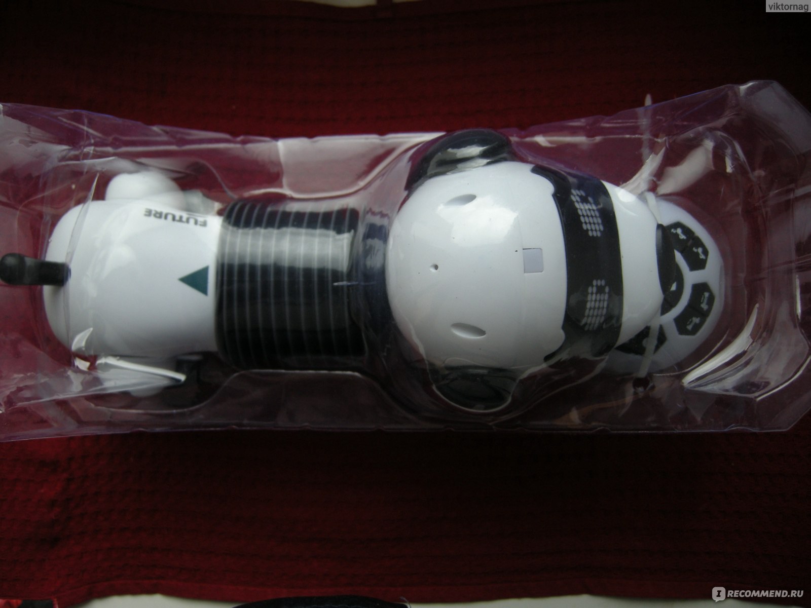
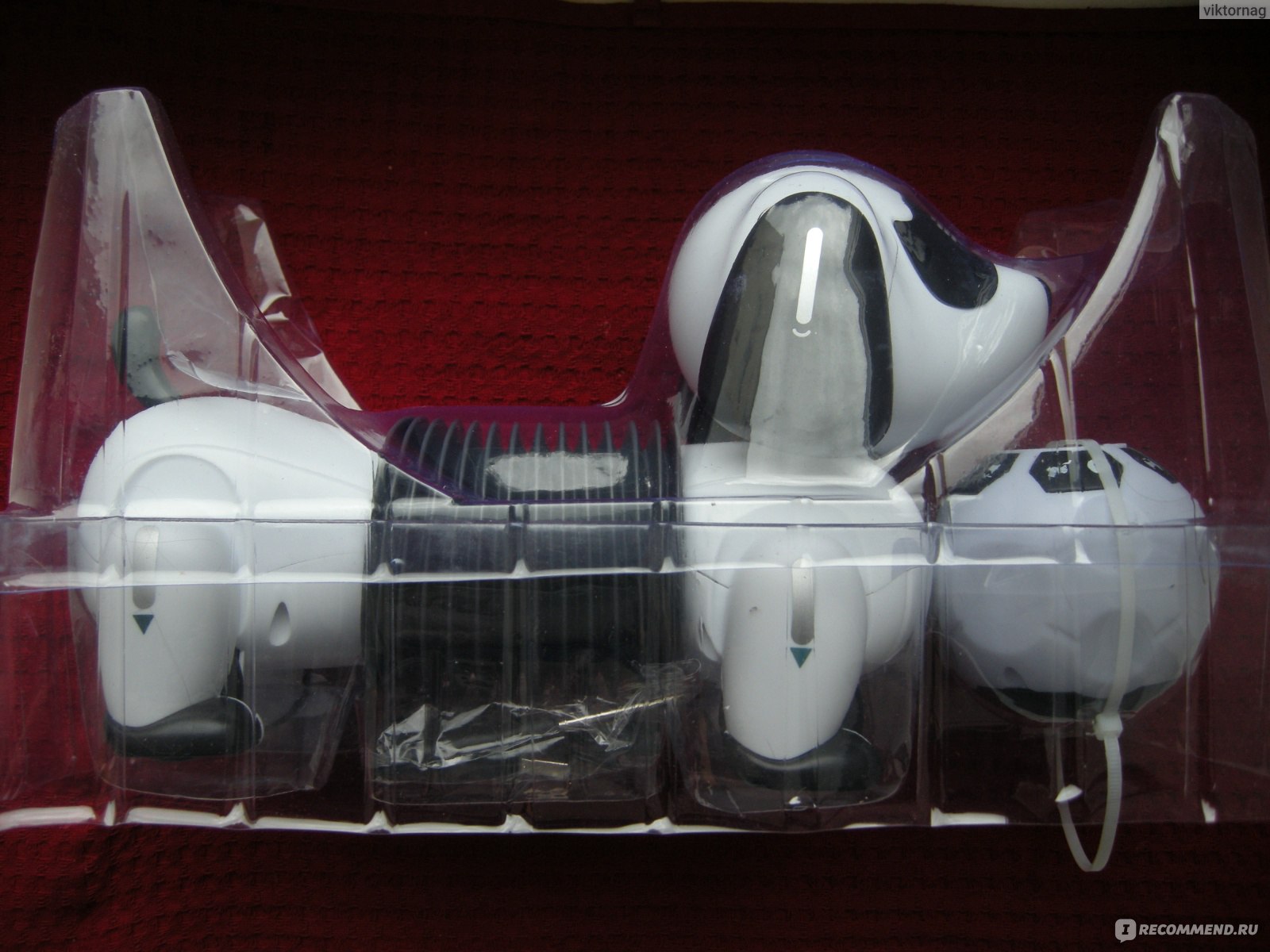
Достаем.
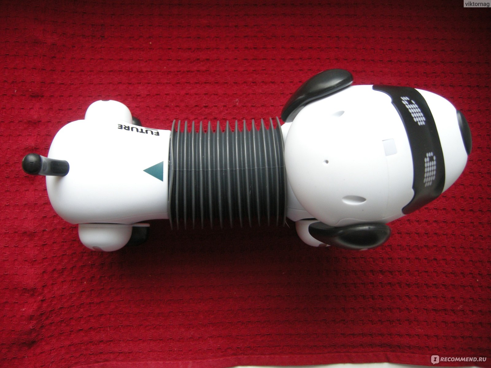
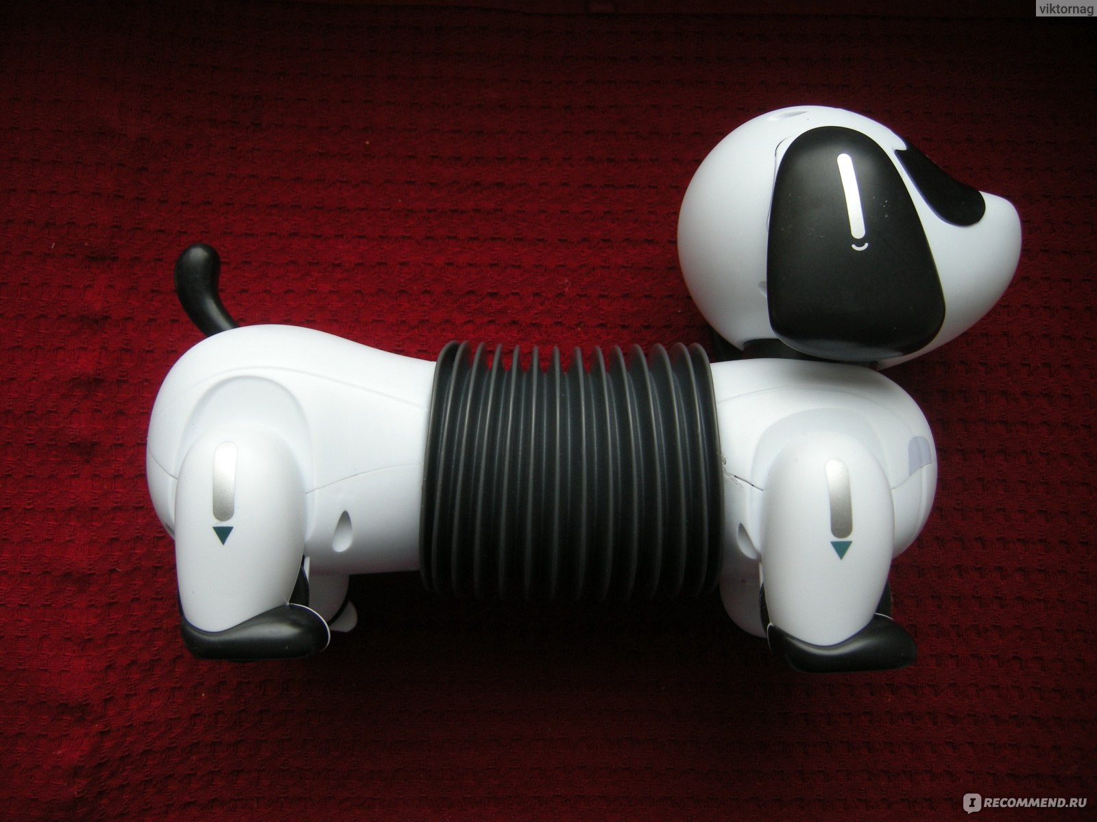
Пёс сделан из АБС-пластика. Это — ударопрочная термопластическая смола. Может спокойно падать со стола.
Довольно симпатичная зверюга.
Кнопка включения, динамик.
Будущее, то есть FUTURE.
Пульт управления в виде шарика.
Соединительный кабель зарядки через USB.
Мятый листочек, который должен изображать инструкцию.
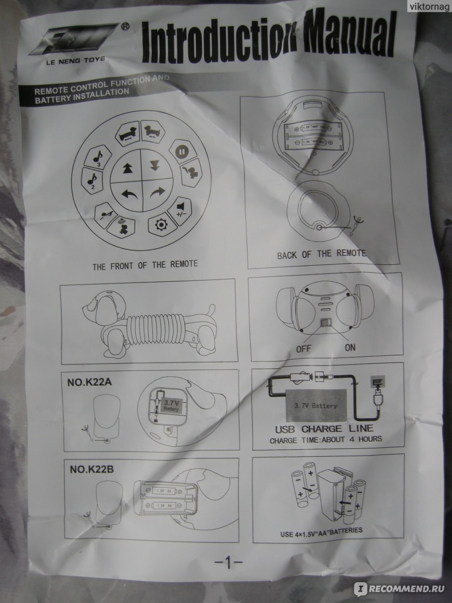
Есть два варианта роботов: с питанием от аккумулятора, № К22А, и от батарей, № К22В. У нас на коробке отмечена модель №К22А. (См. выше).
В пульт управления необходимо вставить две батарейки ААА.
При нажатии на клавишу видно срабатывание.
Да пульт и сам мигает в режиме включено.
Сделано в Китае. Это само-собой.
Разберемся с таксой. Кнопка включения.
Но сначала надо подзарядить аккумулятор. Хотя он пришел не совсем разряженный.
Энергетическая установка таксы находится в ухе. Или за ухом.
В комплекте есть отвертка.
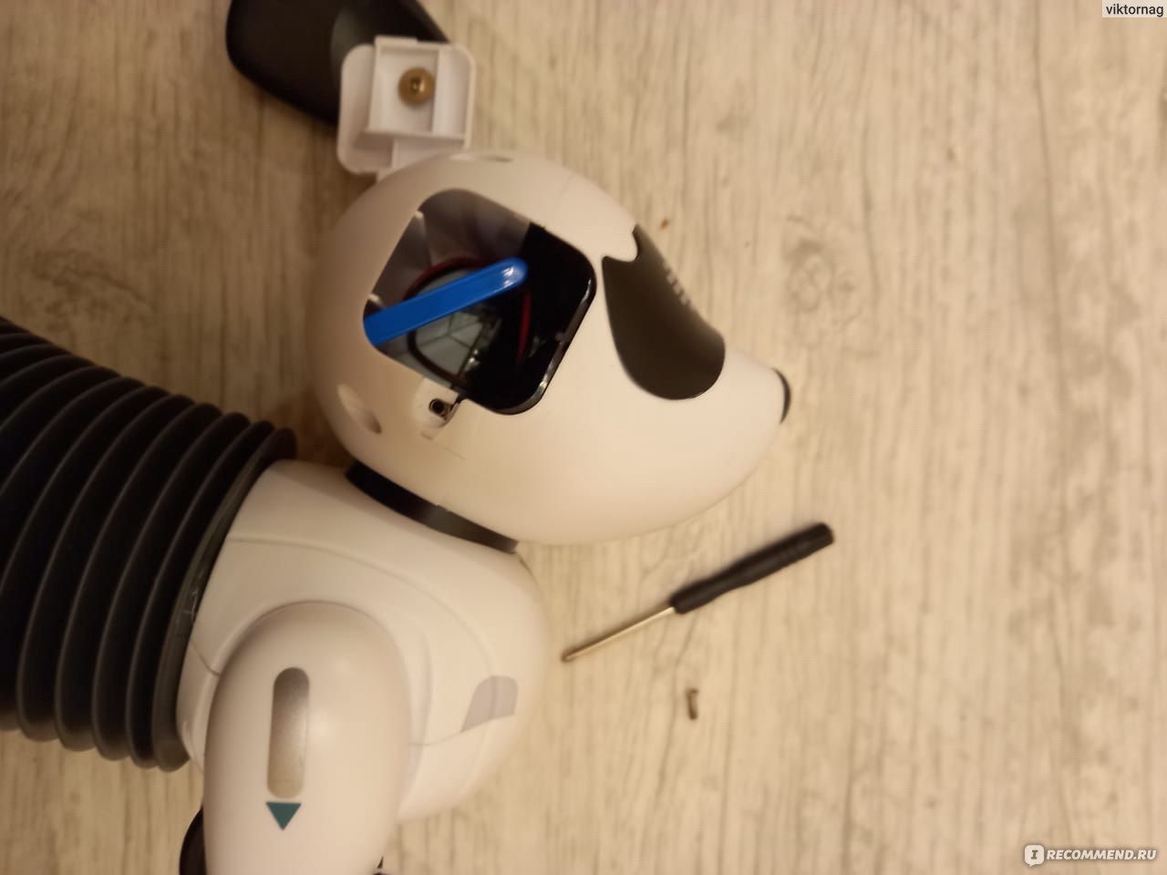
Энергетическая установка — аккумулятор.
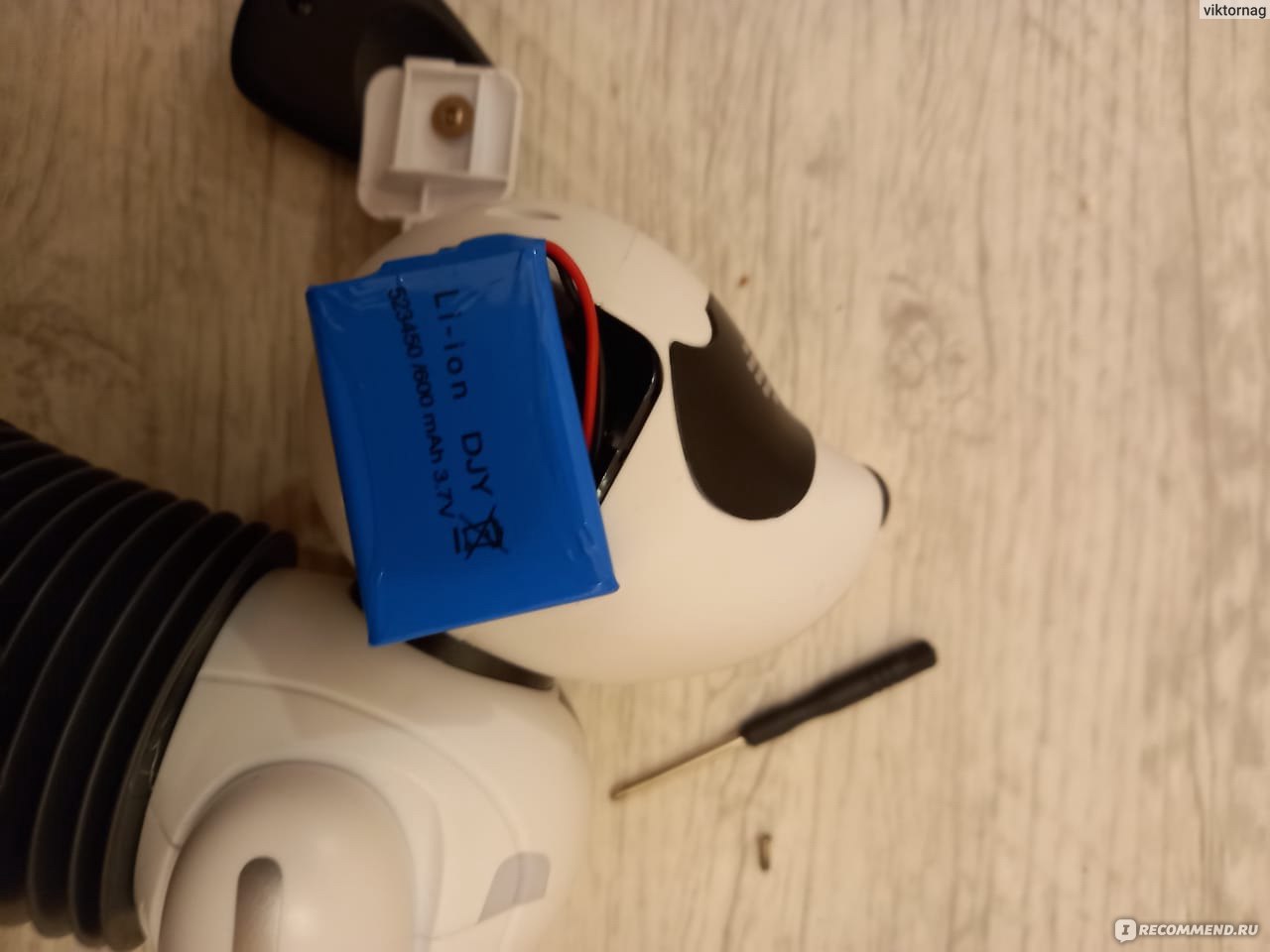
Вот такой марки.
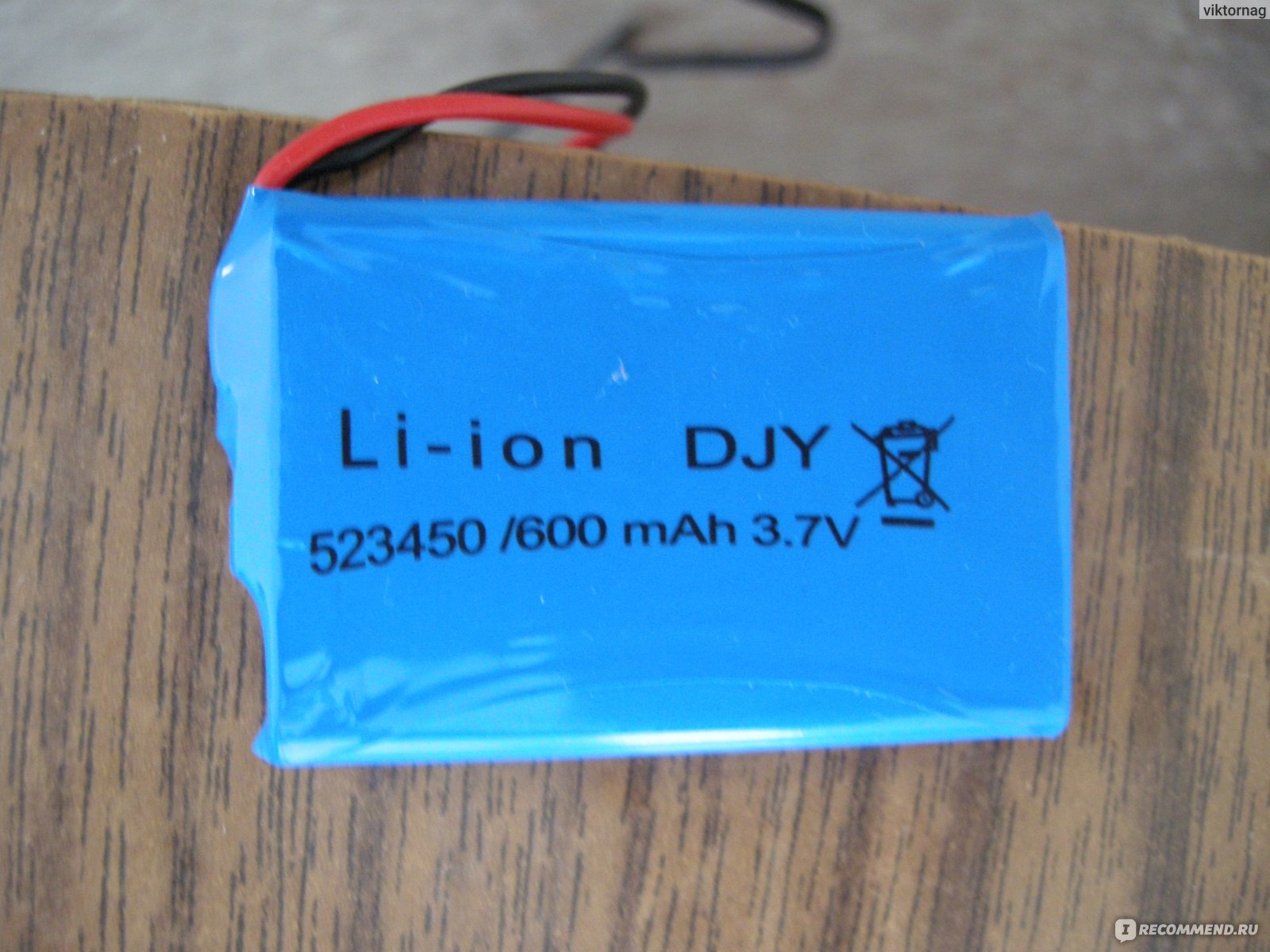
Заряжаем, подключив кабель к любому блоку питания от смартфона.
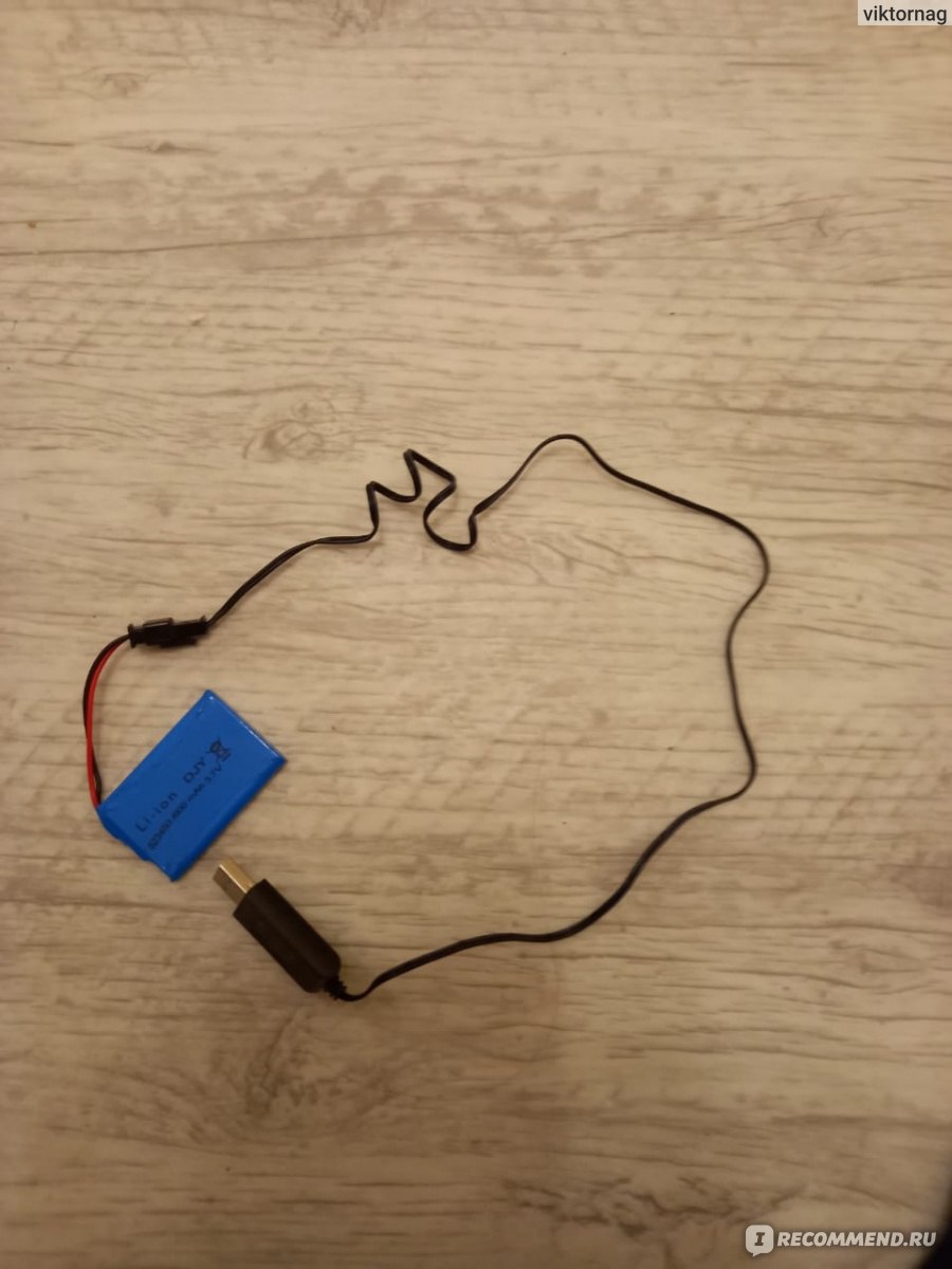
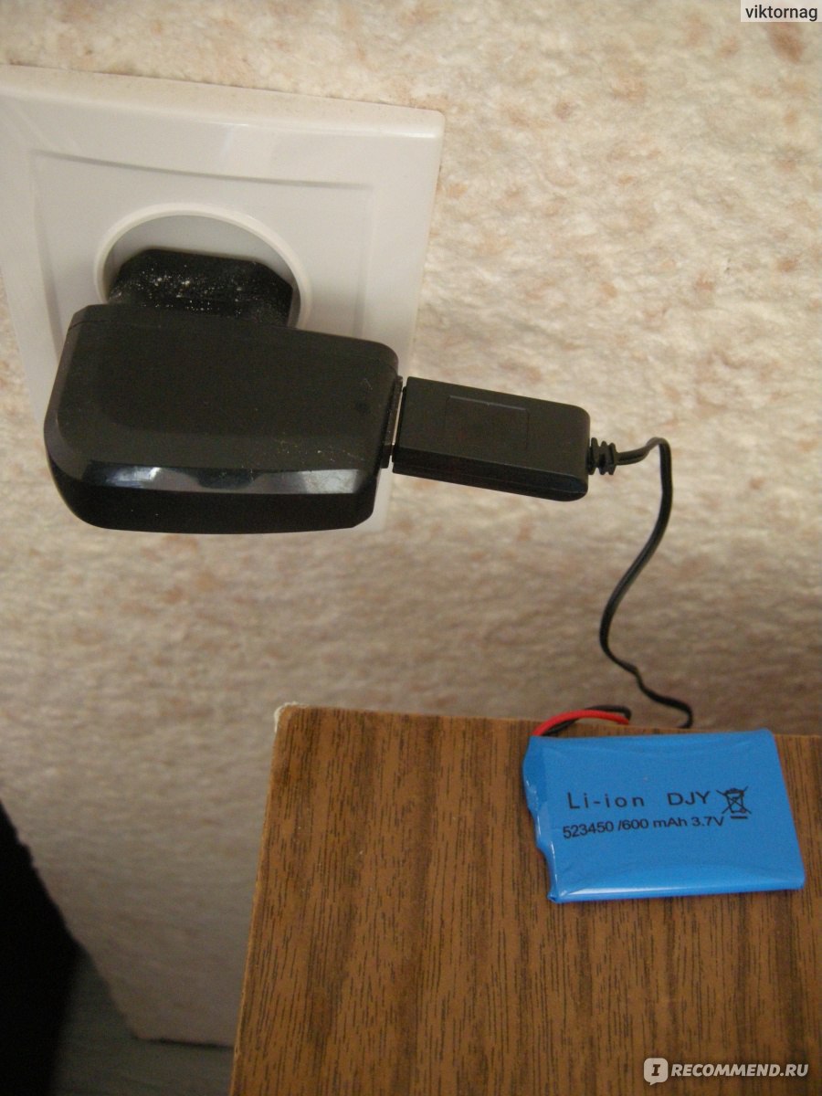
Степень зарядки определяю по нагреву блока питания. Как стал холодным, значит аккумулятор зарядился.
Проверим некоторые функции.
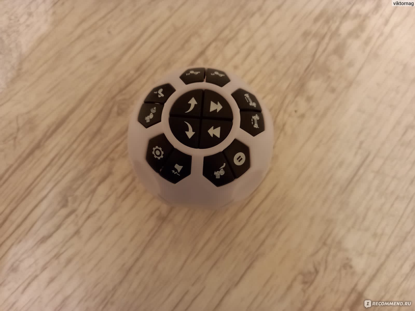
Смотрим нашу мятую инструкцию с другой стороны листа.
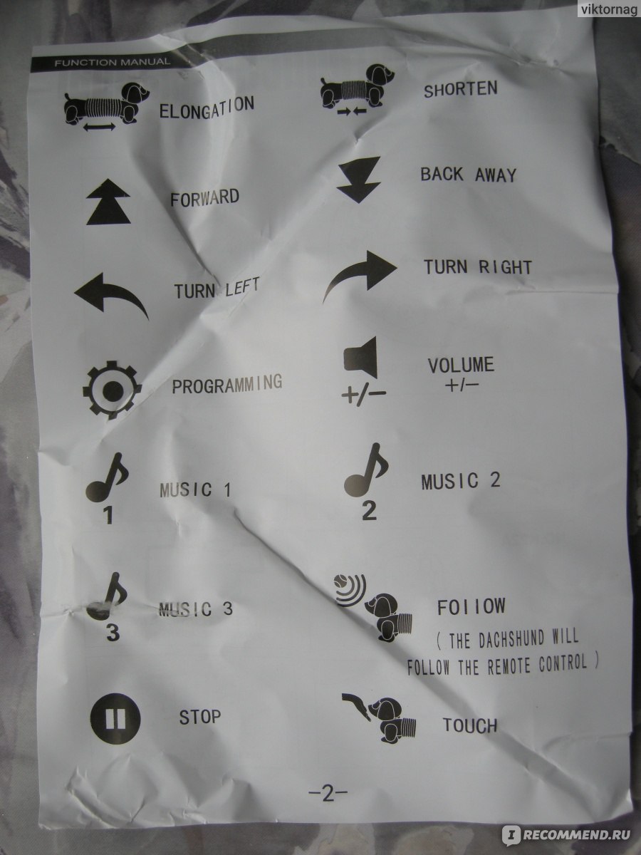
В принципе, тут указаны все функции. Включаем собаку-робота.
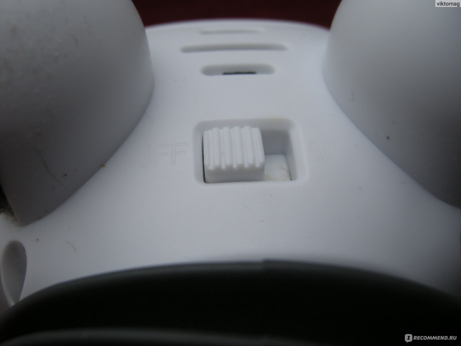
Тут же отверстия для динамика.
Она сразу подает признаки жизни. Но мы нажимаем кнопку «стоп».
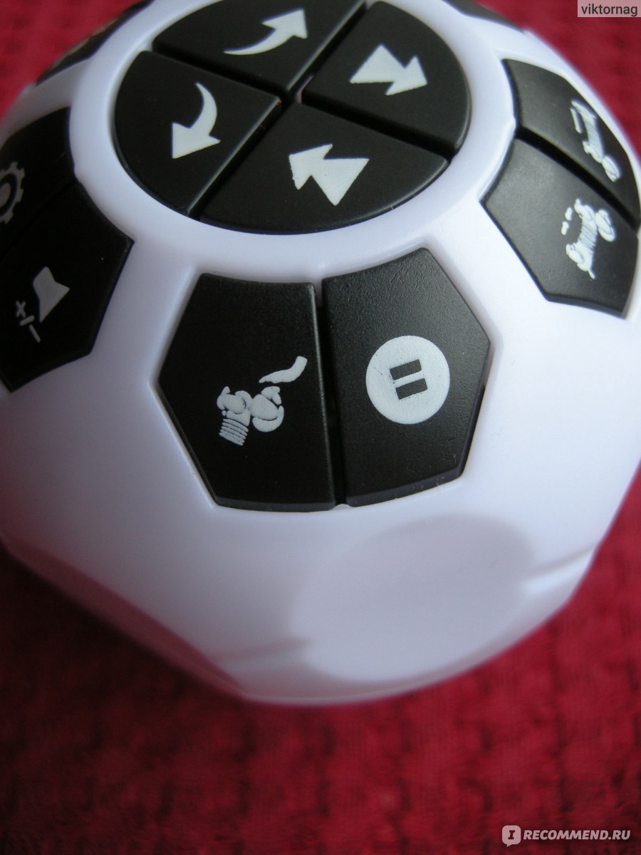
Рядом кнопка управления собакой путем касания носа. Обе функции работают.
Кнопки «увеличения/уменьшения» таксы.
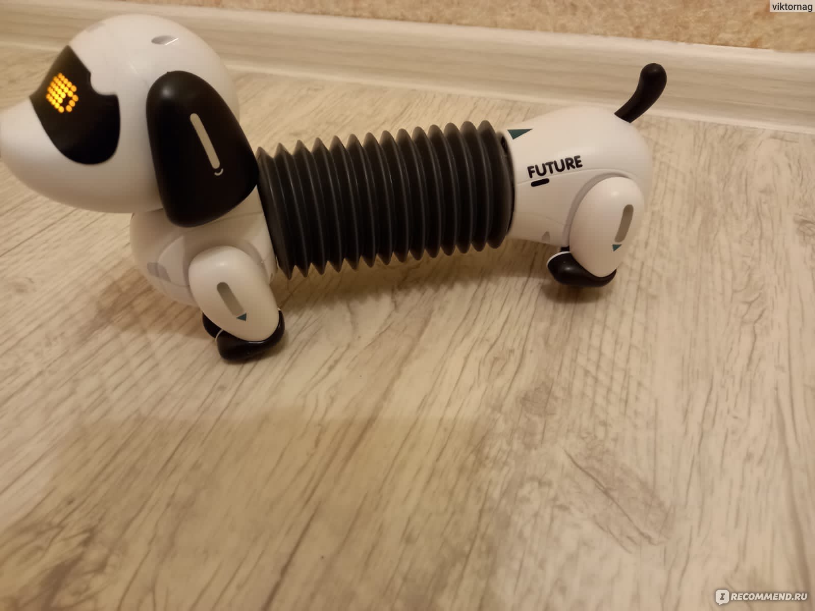
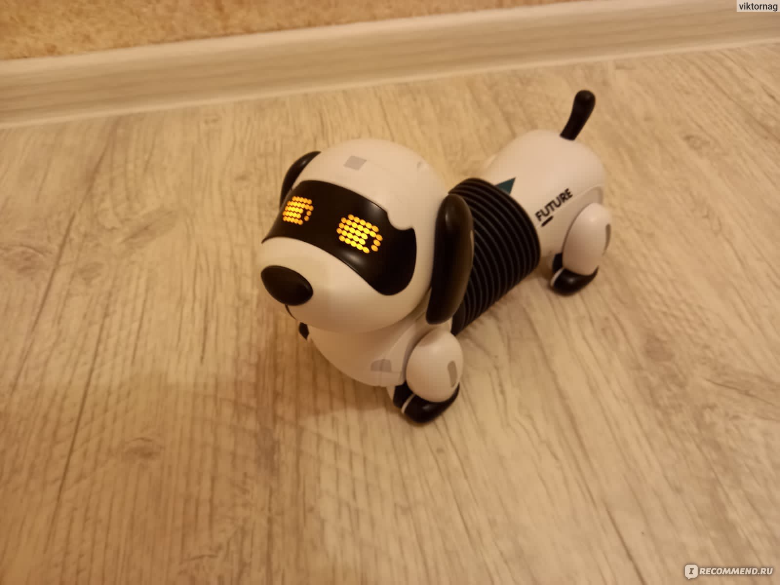
Работают.
Кнопки движения вперед/назад, повороты.
Работают.
Выбор мелодии, три кнопки.
И кнопка следования за пультом. Работают.
Громкость. Работает.
И кнопка настройки. Срабатывает. Но что она делает, мне не понятно.
И как программировать, тоже инструкции нет. И на сайте не объяснено.
Собака ходит за пультом, то есть, его обладателем. Если ее оставить в покое, то через некоторое время напоминает о себе голосом.
Глаза собачьи светятся.
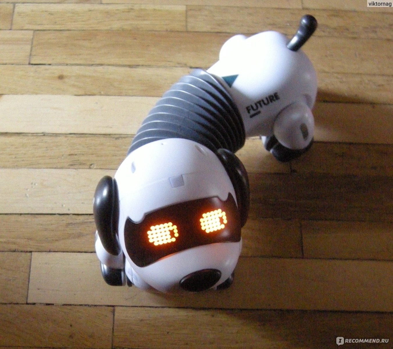
Как движутся ее части, показано стрелочками.
Даже контроль качества есть.
Ладно. Наигрались. Подарим внучке, пока такса цела.
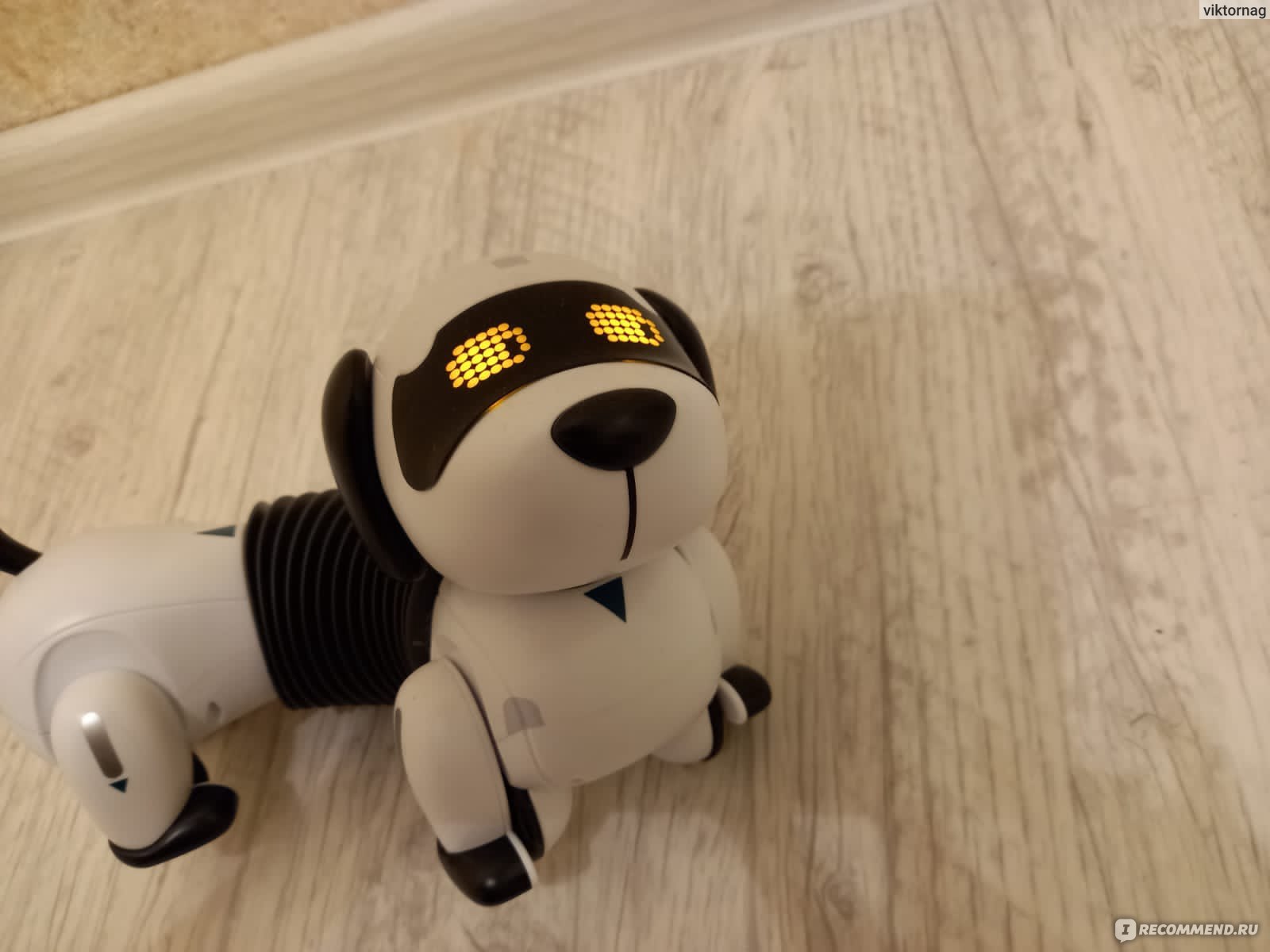
Конечно. Сразу интерес. Все остальные безмолвные подарки побоку.
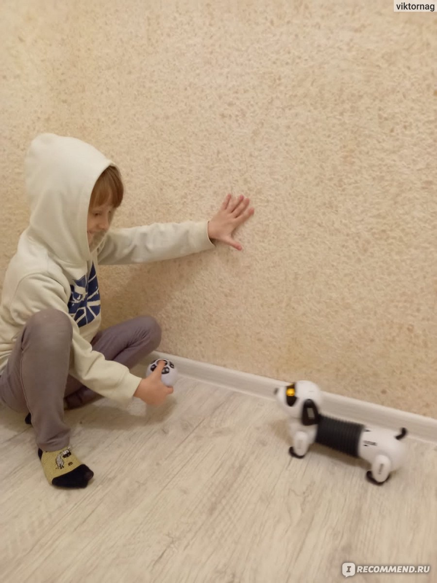
Голос!
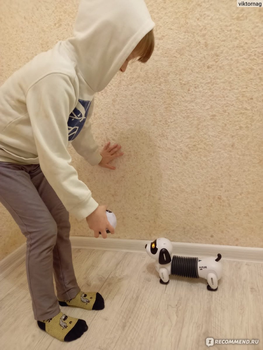
Ко мне!
Все вроде работает.
Через некоторое время я спросил,
— Как собака?
— Иногда играет с ней.
— А сказки?
— Какие сказки?
Принесли мне ее опять. Так как инструкции нет, то читаем на сайте. Собака должна помочь изучать английские слова. По крайней мере, слова CAT и DOG, что указано на сайте даже на рисунке. И на ночь должна рассказывать колыбельную, или какой другой рассказ по-английски. Но добиться членораздельной речи я от этого блохастого не смог.
Так и запишем.
Минусы.
1. Инструкции нет. Тот мятый листочек, который они в запальчивости назвали мануалом, не дает ответа по поводу программирования. Сайт тоже хранит спокойствие по этому вопросу.
2. Такса английский язык не знает. Или не хочет.
3. Сказку на ночь не читает. Не тетя Валя.
А в остальном, прекрасная маркиза, все хорошо, все хорошо.
1. Описанные выше функции собака выполняет.
2. Позволяет себя гладить.
3. Прочная.
4.Мигает глазами.
Возможно, с чем-то и не разобрались. Но мы как-то не пазл покупали. Хочется, чтобы все работало, а не было бы просто рекламой. Тем не менее, вещица забавная. Ребенку прибавило немного радости и занятости.
Рекомендую. Когда есть скидки, то можно и купить.
Но звезд подскостим.
Небольшой обзор на необычную игрушку — программируемого робота на дистанционном управлении.
Робот имеет множество функций, очень интересный для занятий с ребенком, имеет возможность запрограммировать в память последовательность действий.
Дополнительно робот оснащен «ракетницей», что позволяет устраивать игровые баталии)))
Игрушка интересная, неоднозначная, за подробностями под кат.
Всем доброго времени суток! Хотелось бы рассказать всем о моей покупке – о роботе Alpha Smart Robot или, как его уже назвал мой ребенок — робот Никитос)))
Честно говоря, когда ребенок в очередной раз попросил купить ему робота, я задумался т.к. до этого были три неудачные покупки некачественных и дешевых роботов в магазинах города, а тратить более крупную сумму на очередную игрушку не очень хотелось… Решено было искать на просторах интернета, а выбор то огромный! Когда наткнулся на данную модель на китайском сайте, взгляд остановился сразу, потому что подобный, который я видел в магазинах, был с меньшим количеством функций, но почти в два раза дороже. Решено было брать)))
Дополнительная информация — скрин из личного кабинета
Характеристики с сайта:
— Type: intelligent robot
— Frequency: 2.4GHz
— Charging Time: 2 — 3 hours
— Charging Way: USB cable
— Active Time: 30 — 40mins
— Control Distance: 30m
— Battery for Robot: 1 x 3.7V 600mA li-po battery ( built-in )
— Battery for Transmitter: 2 x AA battery ( not included )
— Product weight: 1.004 kg
— Package weight: 1.581 kg
— Package size (L x W x H): 45.50 x 32.00 x 13.50 cm
Посылка шла чуть больше двух недель. Упаковка была из плотного картона, которым так же было обложено прозрачное окно самой упаковки игрушки для дополнительной защиты от нашей почты. Габариты коробки 44 х 30 х 12 см.
Коробка чуть помялась, но не критично, вверху нее удобная для переноски ручка
На коробке присутствует название робота Alpha Robot. Внутри пластиковая вставка белого цвета с роботом
Под роботом уложен остальной комплект: пульт дистанционного управления, стрелы для ракетницы, отвертка и зарядный провод для USB
Внешний вид распакованного робота. Высота игрушки чуть меньше полметра.
В коробке так же прилагались инструкция на английском языке, пульт, отвертка для открытия пульта, 5 стрел с присосками для ракетницы (хотя для заряда требуется три, видимо, пара запасных) и… о, чудо!!! USB-зарядка для самого робота, эту информацию я пропустил, при выборе игрушки, потому и был приятно удивлен, что робот не на пальчиковых аккумуляторах и не батарейках.
А теперь рассмотрим все детально и подробнее))) Сам робот сделан из приличного на вид пластика.
На голове у робота расположен шлем, который в ходе игры можно опускать или поднимать.
Глаза мигают синим цветом (с имитацией движения). А на тыльной стороне головы расположен динамик для передачи звуковых эффектов.
Сзади на спине находится переключатель on/off, индикатор окончания зарядки батареи и входное отверстие, собственно говоря, для самого USB-провода
Спереди на груди присутствует основная кнопка включения дистанционного режима управления
В ногах у робота присутствуют колесики для передвижения
Глаза имеют несколько режимов мигания, в зависимости от активированной функции
Вот фотография катапульты на правой руке робота. можно зарядить до 3х стрел
Обе руки сгибаются помимо трех положений (по бокам, прямо на уровне груди и вверх), так еще и в плече и локтевом суставе.
Вот несколько положений суставов рук для оценки возможностей робота
Можно разводить руки в стороны…
… поднимать их вверх
Так как робот «боевой», то можно устроить бокс ))) Правда нужен второй робот для спарринга)))
Можно сделать прикольный жест руками типа «увы…»
На правой руке зеленый световой сигнал размещен сбоку, а в самой конечности руки есть ракетница на три отверстия, для заряда пульками-стрелами
На левой руке световой эффект так же зеленый, но находится он спереди, подсвечивая перчатку.
При включении переключателя питания сзади, робот начинает работать в Demo-режиме, при этом он сначала на английском произносит, какие конкретно команды он будет выполнять (соответственно названиям кнопок на пульте управления), после чего их выполняет. Для того, чтобы управлять роботом, нужно нажать большую кнопку спереди на груди робота.
Далее подробно опишу пульт. Надеюсь станет понятно, на что собственно способен этот прикольный робот. Для работы пульта необходимы 2 батарейки типа АА (пальчиковые), которые в комплект не входят. Не забывайте выключать пульт и робота по окончанию игры.
Пульт выглядит как большой джойстик с увеличенным количеством кнопок
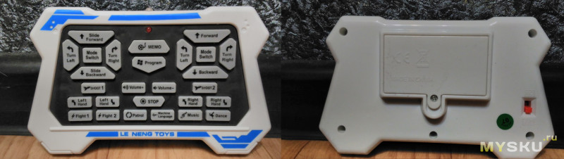
Батарейки для пульта устанавливаются сзади, крышка батарейного отсека сделана под винт, отвертка есть в комплекте
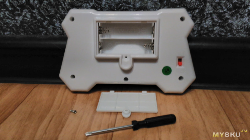
Спереди расположен красный индикатор, который загорается при нажатии любой из кнопок.
Кнопок, кстати целых 27 шт!!!
На фото крупным планом передняя панель пульта. Кнопки сгруппированы в два блока наподобие крестовин джойстика, плюс нижний блок кнопок в три ряда. В центре есть кнопка режимов демо и программирования
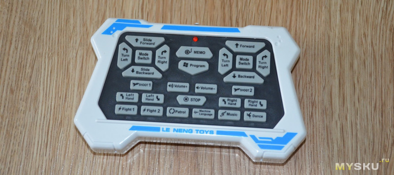
Рассмотрим каждую из них.
— MEMO — запуск Demo версии;
— Program — при первом нажатии запускается режим программирования, после чего ты нажимаешь любые кнопки, затем вторым нажатием завершаешь программирование, и робот выполняет все команды поочередно, что ты задал;
— Volume+ — прибавить громкость;
— Volume– — убавить громкость;
— Stop — остановить все команды.
Группа кнопок езды:
— Slide Forward – робот едет вперед;
— Slide Backward – едет назад;
— Turn Left – разворачивается влево;
— Turn Right – разворачивается вправо;
— Mode Switch – при нажатии этой кнопки можно ускорить или замедлить выполнение команд езды.
Группа кнопок ходьбы:
— Forward – робот идет вперед;
— Backward – идет назад;
— Turn Left – поворачивает влево на 90 градусов;
— Turn Right – поворачивает вправо на 90 градусов;
— Mode Switch – при нажатии этой кнопки можно ускорить или замедлить выполнение команд ходьбы.
— Left Hand (стрелка вверх) – левая рука поднимается вверх, работает в трех положениях;
— Left Hand (стрелка вниз) – левая рука опускается вниз соответственно;
— Right Hand (стрелка вверх) – правая рука поднимается вверх, работает в трех положениях;
— Right Hand (стрелка вниз) – правая рука опускается вниз соответственно;
— SHOOT 1 и SHOOT 2 – два разных режима стрельбы, при которых он выполняет разные движения и звуки;
— Fight 1 и Fight 2 – так же два разных режима боя, при которых он едет в разные стороны, издает звуки, поднимает и опускает руки, имитируя сам бой;
— Patrol – включается сирена, совсем новый звуковой эффект, не похожий ни на какой из других режимов, робот ходит, патрулирует по всем сторонам;
— Machine Language – разговорная речь становится похожа на звуки инопланетян из мультфильмов;
— Music – играет красивая музыка (сколько всего песен, так и не смогла понять), при этом робот хаотично двигается;
— Dance – играет музыка, робот танцует в ритм.
Как вы уже поняли, движений очень много, игра долгая и интересная получается.
Пара фотографий робота при игре. Вид справа
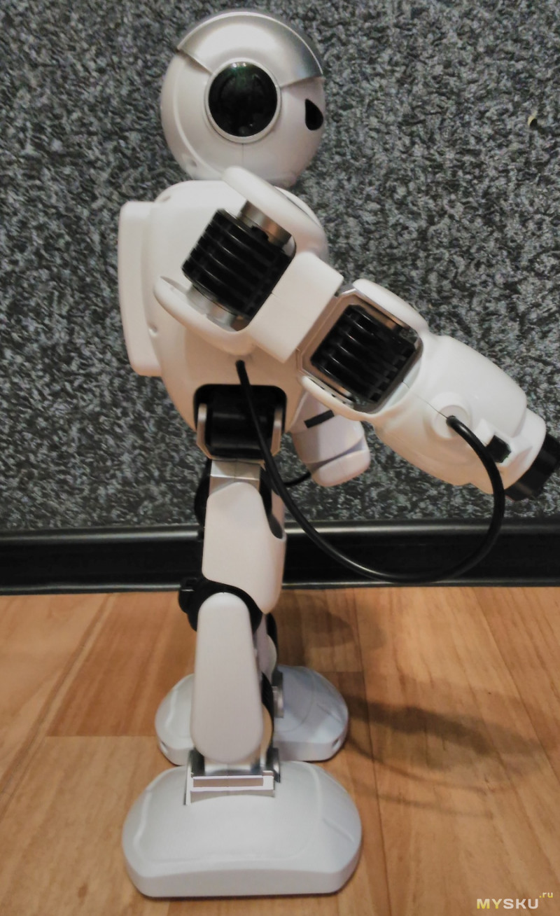
Вид слева
Робот патрулирует в поисках цели, вооружен и опасен
Устранили нарушителя в виде стиральной машинки
Робот поднял руки вверх — сдается. Боекомплект расстрелян))))
Робот заряжен опять
Анимация подъема и опускания шлема
Анимация мигания глаз робота
Небольшое видео, иллюстрирующее функциональность робота
Как вы уже поняли, движений очень много, игра долгая и интересная получается. У нас с ребенком всегда были проблемы с игрушками на дистанционном управлении, вечно они не вписывались в поворот, с трудом обходили препятствия и т.д.
Но с этим — другое дело)) Во-первых, робот очень устойчив перед препятствиями, во-вторых, способен маневрировать, как говорится, на высшем пилотаже.
Не смотря на большое количество кнопок, ребенок с ним разобрался легко и быстро. Особое веселье у моего ребенка вызывает то, что у этой модели робота можно стрелять прицельно. То есть, не просто запускаешь режим стрельбы, и он стреляет в одну точку, а наводишь руку и имеешь возможность прицелиться в то место, куда тебе нужно попасть. Это хорошо просматривается на видео. Так что этот робот по всей квартире охотился за мной)))
Еще его преимущество для меня, как для родителя, заключается в том, что звук можно регулировать от тихого режима до существенно громкого. А плюс в том, что ребенок, проснувшись и схватив свою любимую игрушку с самого утра, все-таки дает мне время еще чуток поспать)))
Так же хочу отметить, что полного заряда нам хватило на три дня игры, при этом передвигается робот по ковру так же хорошо, как и по линолеуму/ламинату. Мы с ребенком в полном восторге, особенно если учесть, что я долго не отдавал ребенку в первый раз пульт, увлеченный игрой, то еще не известно кто больше в восторге)))
Подведу итог.
Плюсы: довольно быстрая доставка; качество действительно на высоте; большое количество режимов игры; игра, как на полу, так и на ковре, продолжительный заряд; красивый дизайн; достаточно низкая цена сравнительно с другими роботами данной функциональной линейки по сравнению с магазинами.
Минусы: несколько сложное управление (много функций), перед игрой надо разбираться что к чему
Всем пока! Хороших вам игрушек и занимательных игр)))
Робот-пылесос — это действительно удобный девайс. Он не заменит полностью обычный пылесос, но существенно снизит количество необходимых генеральных уборок в жилом помещении. Если верить отзывам, то в большинстве случаев этим приходится заниматься всего 1 раз в 2 – 3 месяца. Без робота-пылесоса — практически каждые 2 недели. Так что такую технику покупать все же имеет смысл. Но у потребителей нередко возникают сложности с первичной настройкой робота. Как это сделать и с какими нюансами можно столкнуться?
Содержание:
- Как подготовить квартиру
- Как определить место для установки зарядной станции
- Подключение к WiFi
- Подключение робота-пылесоса к приложению
- Что делать, если не подключается
- Как настроить робот-пылесос без приложения
- Функционал приложения для синхронизации робота-пылесоса
- Голосовое управление
- Выбор зон для уборки
- Расписание
- Выбор режима уборки
- Самодиагностика пылесоса
- Распространенные проблемы и их решения
- Пылесос не подключается к WiFi
- Приложение выдает ошибку типа «поднесите смартфон ближе к роутеру»
- Робот-пылесос пропускает темные участки на карте
Как подготовить квартиру
Перед запуском уборки роботом-пылесосом потребуется:
- Установить зарядную станцию и полностью зарядить робот-пылесос.
- Убрать с пола все хрупкие предметы, которые пылесос теоретически может столкнуть. Различные вазы, цветочные горшки. В некоторых моделях для этого предусмотрена функция добавления «виртуальных стен». Но для её использования пылесос должен составить предварительную карту помещения, то есть выполнить хотя бы одну уборку.
- Установить фильтр, пылесборник.
Перед покупкой робота-пылесоса рекомендуется замерять высоту от пола до нижней грани имеющихся диванов, шкафов, постелей. И выбирать ту модель, которая «сможет» убраться под ними.
Рекомендуем посетить рейтинг: ТОП-15 лучших роботов-пылесосов 2022-2023 года.

Как определить место для установки зарядной станции
Зарядную станцию следует размещать в таком месте, чтобы на расстоянии в 30 – 40 сантиметров с её боков, а также спереди было свободное пространство. Только в этом случае пылесос сможет самостоятельно становиться на подзарядку. В противном случае он может банально застрять, что приведет к его полному разряду. Ну и при таком раскладе назвать робот-пылесос автономным не получится. А ведь именно для этого его приобретают: для уборки помещения без необходимости контроля со стороны человека за его работой.
Подключение к WiFi
Подключать робот-пылесос к WiFi не обязательно. Он может выполнять уборку и без этого. Но синхронизация с мобильным приложением существенно расширяет его функционал. В частности, у пользователя появится возможность задать расписание, отредактировать интерактивную карту, задействовать голосовое управление и так далее.
Алгоритм подключения к WiFi у большинства роботов-пылесосов следующий:
- На мобильный телефон установить фирменное приложение от производителя. Ссылка на него чаще всего указывается в руководстве пользователя (может приводиться в форме QR-кода).
- Авторизоваться в мобильном приложении. Выбрать «Добавить устройство». В этот момент включить робот-пылесос (с помощью кнопки на корпусе).
- Из списка обнаруженных девайсов указать пылесос.
- Ввести пароль от WiFi-сети.
Перед синхронизацией пылесос рекомендуется полностью зарядить. Это может занять от 2 до 5 часов, в зависимости от емкости установленной аккумуляторной батареи.
Рекомендуем посетить рейтинг: ТОП-10 лучших роботов-пылесосов Xiaomi 2022-2023 года.

Подключение робота-пылесоса к приложению
С подключением проблем, как правило, не возникает. Самое главное установить программу, которую рекомендует использовать производитель. А далее останется только запустить её и следовать пошаговой инструкции. При первом запуске приложения могут запрашиваться разрешения на доступ к внутренней памяти смартфона, к GPS-координатам и так далее. Рекомендуется все эти запросы предоставлять. Всё это нужно для более правильного позиционирования пылесоса в пространстве.
Что делать, если не подключается
Чаще всего это происходит по следующим причинам:
- Установлено не рекомендуемое приложение. Нужно уточнить, какое следует использовать.
- Домашний WiFi имеет шифрование, отличное от WPA2 (выставляется в настройках маршрутизатора).
- Приложению для синхронизации предоставлены не все необходимые разрешения.
- Ранее робот-пылесос уже был синхронизирован с другим устройством. Рекомендуется выполнить сброс его настроек WiFi. А как это выполняется указано в инструкции. Как правило, нужно зажать одновременно кнопку включения и клавишу автоматической постановки пылесоса на зарядную станцию.
Как настроить робот-пылесос без приложения
Робот-пылесос можно использовать и без приложения. Функционал от этого будет ограничен, но уборку он все же сможет выполнять. Как именно настраивать пылесос конкретной модели детально описывается в инструкции.
В большинстве случаев работают следующие алгоритмы:
- Нажатие кнопки включения переводит пылесос в рабочий режим.
- Ещё одно нажатие кнопки включения запускает проведение уборки в стандартном режиме.
- Двойное нажатие кнопки включение переключает мощность всасывания.
- Зажатие кнопки включения на 3 – 4 секунды активирует режим локальной уборки. То есть пылесос принимается убирать участок примерно 1,5 на 1,5 метра.
- Нажатие кнопки постановки на зарядку отправляет пылесос на зарядную базу.
Рекомендуем посетить рейтинг: ТОП-12 лучших роботов-пылесосов с влажной уборкой 2022-2023 года.
Функционал приложения для синхронизации робота-пылесоса
С помощью приложения потребитель может воспользоваться следующими функциями:
- голосовое управление;
- выбор зон для уборки;
- расписание;
- выбор режима уборки (траектория движения, мощность);
- самодиагностика пылесоса.
Голосовое управление
Доступно не во всех моделях. Позволяет запускать или останавливать уборку, планировать её при помощи голосового ассистента смартфона (например, Google ассистент, Яндекс Алиса).
Выбор зон для уборки
Данная функция предусмотрена в тех моделях, где есть составление интерактивной карты. На экране смартфона пользователь может указать, какие комнаты нужно убирать, какие места — пропускать. В более простых моделях для этого используется магнитная лента.
Расписание
Данная функция позволяет составить расписание для проводимых уборок на 7 – 10 дней вперед. Удобно, ведь можно задать, что пылесос будет убираться в доме только тогда, когда все на работе (или на учебе). То есть он никому не будет мешать.
Выбор режима уборки
Позволяет задать траекторию движения (по периметру, зигзагом), а также мощность всасывания. В некоторых моделях ещё имеется возможность активировать автоматическую подзарядку для последующего завершения уборки в помещении.
Самодиагностика пылесоса
Приложение «напомнит» пользователю, когда нужно опустошить пылесборник, очистить фильтр или снять насадку для влажной уборки помещения. Также через приложение можно узнать текущий уровень заряда, примерное оставшееся время до окончания уборки помещения.
Рекомендуем посетить рейтинг: ТОП-10 лучших бюджетных роботов-пылесосов 2022-2023 года.

Распространенные проблемы и их решения
Самые распространенные проблемы, с которыми сталкиваются пользователи:
- пылесос не подключается к WiFi;
- приложение выдает ошибку типа «поднесите смартфон ближе к роутеру»;
- робот-пылесос пропускает темные участки на интерактивной карте.
Пылесос не подключается к WiFi
В большинстве случаев решается выбором метода шифрования беспроводной сети WPA2. А также сбросом настроек WiFi самого пылесоса. Если это не помогает, то рекомендуется также переустановить приложение. И в дальнейшем, если проблема повторяется, обращаться в сервисный центр производителя.
Приложение выдает ошибку типа «поднесите смартфон ближе к роутеру»
Чаще всего эта ошибка возникает в пылесосах от Xiaomi. И в 99% случаев устраняется выставлением в настройках приложения MiHome региона «Материковый Китай» или «Сингапур». После успешной синхронизации настройки можно поменять обратно.
Робот-пылесос пропускает темные участки на карте
А это означает, что пользователь случайно добавил зоны, которые пылесос будет пропускать. Или же у него банально загрязнились оптические датчики, размещенные внизу и по бокам. Их рекомендуется очищать от пыли сухой мягкой тряпкой.
Итого, настроить робот-пылесос после покупки может показаться сложно. Но на практике все это занимает 5 – 10 минут. И после этого пылесос будет работать почти в полностью автономном режиме. Нужно лишь не забывать опустошать его пылесборник и регулярно чистить датчики от пыли.

Для работы проектов iXBT.com нужны файлы cookie и сервисы аналитики.
Продолжая посещать сайты проектов вы соглашаетесь с нашей
Политикой в отношении файлов cookie
Для тех, кто не хочет настраивать китайское облако и использовать смартфоны – достаточно выбрать подходящую модель робота пылесоса, управляемого … с помощью привычного пульта дистанционного управления (ДУ). Далеко не во всех случаях возможно развернуть WiFi сеть с полным покрытием по всем комнатам и одновременным доступом в интернет, да и людям старшего возраста будет сложно научиться управлять через приложение. В таких случаях проще подобрать модель робота-пылесоса с теми же функциями и дополнительным управлением с помощью пульта ДУ. На что обращайте внимание при выборе: наличие функции влажной уборки, наличие лазерного лидара. На самом пульте должен быть запуск автоматического режима уборки, ручного управления/перемещения, режим контурной уборки, отмена/пауза/возврат на базу. Ряд продвинутых пультов позволяет активировать уборку по расписанию (по таймеру) непосредственно с пульта ДУ.
Робот-пылесос REDMOND RV-R650S
Одна из доступных моделей — это умный робот-пылесос REDMOND RV-R650S с режимом сухой/влажной уборки. Модель примечательна дополнительной стерилизацией с помощью ультрафиолетовой лампы, расположенной на нижней части корпуса. Управление осуществляется как с помощью приложения и голосовых помощников (умных колонок), так и с помощью пульта дистанционного управления из комплекта.
Робот-пылесос Liectroux XR500
Доступны и более дешевые варианты. Хорошим примером будет свежая модель робота-пылесоса XR500 от Liectroux. Модель оснащена лазерным лидаром, работает с приложением, умеет строить карты и избегать падения с лестниц. Также, как и у предыдущей модели, предусмотрена функция сухой и влажной уборки. А самое главное — имеется удобный пульт ДУ с дисплеем, позволяющий не только активировать автоматический режим уборки, но и выбрать интенсивность, установить таймер работы. Тестирование и обзор доступны по ссылке.
Робот-пылесос Midea I5C
Еще один бюджетный вариант робота-пылесоса с пультом дистанционного управления предлагает Midea. Модель Midea I5C умеет выполнять не только сухую, но и влажную уборку. Предусмотрено подключение к смартфону через WiFi и управление из приложения. А вот лазерная навигация отсутствует. С другой стороны Midea I5C стоит всего около 7’500 рублей (~ $150), что весьма неплохо для подобного функционала.
Робот-пылесос ILIFE V80 MAX
Довольно интересную модель предлагает ILIFE. Это робот-пылесос V80 MAX с пультом управления в комплекте. С пульта доступно управление автоматической уборкой, контурной уборкой, регулировкой интенсивности, а также установка расписания уборки. Вместительные резервуары для мусора и воды позволяют работать длительное время в автономном режиме. Высота профиля всего 8 см, что позволяет перемещаться под мебелью на ножках. Выступающих надстроек нет, лазерного лидара нет. Тестирование и обзор доступны по ссылке.
Роботы-полотёры iLife W400 и W450
Довольно оригинальный вариант есть у ILIFE — это модели роботов серии W400 с функцией влажной уборки. Представляет собой роликовый полотёр с управлением с помощью пульта ДУ. Моет и протирает качественно, если полы сильно грязные. Механизм с вращающимся роликом позволяет проводить очистку напольных покрытий на большой площади в автоматическом режиме, а достаточно объемный бак для отходов даёт возможность длительное время работать без обслуживания. Подробные обзоры доступны по ссылкам: тестирование ILIFE W400 и тестирование ILIFE W455/450.
Таким образом, даже недорогие модели роботов-пылесосов могут быть не только удобны в управлении, но и простыми в освоении для людей без опыта работы с умной техникой, особенно для людей старшего возраста. Подобные модели будут востребованы как для собственного использования, так и в качестве презента маме/бабушке. Сохраняйте себе эту подборку, рекомендуйте друзьям! С другими тестами и обзорами смарт-гаджетов и техники, а также подборками вы можете ознакомиться по ссылкам ниже и в моем профиле.
Сейчас на главной
Новости
Публикации
Сегодня мы вновь поговорим о беспроводных микрофонных системах в лице Kimafun KM-G70. Которая, как обычно, может сама выступать в роли микрофона или же работать через петличку на 3.5 мм. В…

Обновленный аккумуляторный пылесос Dreame T20 — это отличная модель легкого и компактного вертикального пылесоса с двигателем 450 Вт и временем работы более 1 часа. В комплекте предлагается…
Сегодня удивить кого-то наличием беспроводных
наушников уже невозможно. Но существуют линейки, в которых каждая новинка
становится интересней, а их функционал расширяется. В данном обзоре…

Небоскребы появились в США сто лет назад, сейчас их строят по всему миру. Некоторые высотные здания хорошо известны, и часто посещаются туристами, как 828 метровая башня Бурдж-Халифа в Дубае, а…

Популярность бьюти-гаджетов для ухода за кожей в домашних условиях набирает обороты. Именно они сделали аппаратные процедуры для лица и тела доступными широкому кругу пользователей и позволили…

Мы
продолжаем рассказывать про серию небольших музыкальных колонок от бренда ELTRONIC.
Сегодня наше внимание привлекла ELTRONIC LIVE 20-74. Назвать ее совсем
компактной нельзя, при высоте 11 см и…
Программа дистанционного управления роботом пылесосом через смартфон или айфон требует предварительной установки. Непременное условие для дистанционного управления гаджетом – наличие Wifi в доме. Назначение приложения Xiaomi (MiHome) -связать владельца с инструментом дистанционно. После этого можно управлять роботом из любой точки планеты, где есть интернет связь.

Содержание
- 1 Приложение для пылесоса Xiaomi
- 2 Подключение пылесоса Xiaomi к приложению на русском языке
- 3 Как подключить робот пылесос Xiaomi к приложению «Умный дом»
- 4 Видео
Имеющиеся в продаже роботы пылесосы Xiaomi с управлением Smart снабжены программой, которая не распознает российские регионы. Для обеспечения связи необходимо использовать азиатские или европейские домены. Информация на гаджете после установки подается на китайском языке. А сама программа MiHome совмещается с ОС Андроид, подходит для установки на смартфон.
Чтобы установить на телефон приложение для робота пылесоса Xiaomi, нужно выполнить следующие действия. Руководствуясь инструкцией к аппарату, подключить базовую станцию, поставить робот на зарядку и дождаться, когда светодиод на корпусе будет гореть ровным белым светом – устройство готово к работе. На телефоне активировать функции GPS, Bluetooth и Wi-Fi. Скачать приложение к роботу пылесосу Ксиаоми можно в магазинах приложений, например, «Play Market». Здесь нужно найти иконку пылесоса и кликнуть. В это время пылесос должен быть включен.
Дальше следует авторизация, получение запрашиваемых разрешений и добавление устройства вручную, если в меню таковой не значится. После успешного контакта откроется меню, здесь нужно указать наименование сети и пароль Wifi. При подключении поднести телефон как можно ближе к маршрутизатору. Пылесосу следует задать имя и определить его место дислокации, например, кухня. Рабочий стол приложения.

Если синхронизация программы пылесоса Ксиаоми прошла успешно, на экране появится пылесос. Уже можно воспользоваться кнопками Clean и Dock. Для управления процессом уборки нужно перейти в раздел «Настройки» — 3 точки в верхнем углу и выбрать нужные опции:
- Timer – настройка уборки по расписанию с указанием дня и часа.
- Cleanup mode – режимы уборки от малошумного до максимального.
- Care – износ расходников в %.
- Remote Control – дистанционное ручное управление роботом.
Не все в подключении проходит гладко, бывают сбои, приложение Xiaomi Mi Robot может не видеть пылесос, а связь временами пропадать. Причина в неустойчивости соединения и отсутствии адаптации. Поможет перезагрузка, смена региона с переустановкой программы или VPN. Запуская приложение, нужно выбрать регион. Для российских пользователей Xiaomi Robot Vacuum Cleaner Lite подходит только Южная Корея. Для других роботов пылесосов Сяоми можно подключить программу через Германию или Китай.

Подключение пылесоса Xiaomi к приложению на русском языке
Чтобы сменить язык общения через смартфон с роботом пылесосом, нужно воспользоваться переведенной программой. Для перехода на русскую версию приложения Xiaomi, выполняются действия.
- Установить новую версию MiHome на русском языке – MiHome1.39_ru_Opel.ark. Открыть можно с помощью приложения ZIP Extractor.
- Закачать нужные плагины на русском языке.
- Файлы заложить в память телефона используя проводник, например, ES. Путь – plugin/install/mpk.
- Найти папку по присвоенному цифровому имени и заменить плагины в основной программе на русскую версию.
- Запустить Xiaomi пылесос с приложением на русском и проверить правильность установки.
Голосовой ответчик продолжает использовать непонятный язык? Следует найти соответствующее приложение и обучить пылесос Xiaomi общаться на русском. Скачать программу MiHomeот vevs. Под спойлером «Языковые пакеты» выбрать пакет «Максим универсальный». Потребуется скачать улиту для прошивки Win, распаковать ее и поместить в каталог voicepacks.
Поместить улиту нужно на диск С в раздел, где пылесос и ПК находятся в одной сети. Выбрать и прошить голосовой пакет из приложения. Таким образом, голосовой помощник робота пылесоса Xiaomi обучается русскому языку.

Как подключить робот пылесос Xiaomi к приложению «Умный дом»
При всех достоинствах системы умного дома Xiaomi, она ориентирована на пользователей, владеющих китайским языком. Нет даже англоязычной версии программы. Как добавить пылесос Xiaomi в приложении? В системе управления умным домом для подключения гаджетов используется шлюз HomeKit от Apple для совместимости различных приборов с управлением через телефон.
Основой управления умным домом лежит система управления инструментами MiHome разработчика Xiaomi. Все интеллектуальные домашние приборы объединяются в сеть, управляются из общего центра. Программа для пылесоса Xiaomi адаптирована для использования в блоке. Для каждого прибора отведено место в программном обеспечении. Нажав на иконку, пользователь получает доступ к панели управления конкретным прибором.
Приложение MiHome, в момент установки связи с пылесосом роботом Сяоми, отводит место гаджету в системе умного дома. Это происходит в момент, когда прибор определяется в меню или добавляется, с указанием дислокации. Никаких дополнительных действий не требуется.

Возможно, программа пылесоса Xiaomi станет первым обитателем системы умный дом. Но в будущем ядро примет на себя регулирование освещения, температурного режима и управление другими роботизированными системами.
Основным недостатком комплекса является неприятие языков. Регулируется процессор по часовому поясу Китая, в России официально нет магазинов, сервисного обслуживания, гарантии от производителя. Включенная в умный дом программа для управления пылесосом Xiaomi должна быть официальной, только на китайском языке.
Производитель заявил, с 2018 года начнет локализацию на российский рынок. Здесь обещается открыть специализированные магазины, а приложение для управления пылесосом Xiaomi выпускать на русском языке.
Видео
Порядок подключения пылесоса Xiaomi Mi к умному дому.