
Edit on GitHub
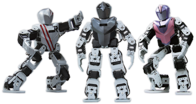
- Excellent walking humanoid (Self-Adjusts posture while walking)
- Various sensors including Gyro, Distance, and IR
- Remote control capability (IR-default, Bluetooth-optional)
- C-style programming & motion teaching with RoboPlus S/W (USB interface included)
- Semi-transparent humanoid skin for customization
- Digital packet communication with daisy chain topology
- Build various robots through versatile expansion mechanism
Getting Started
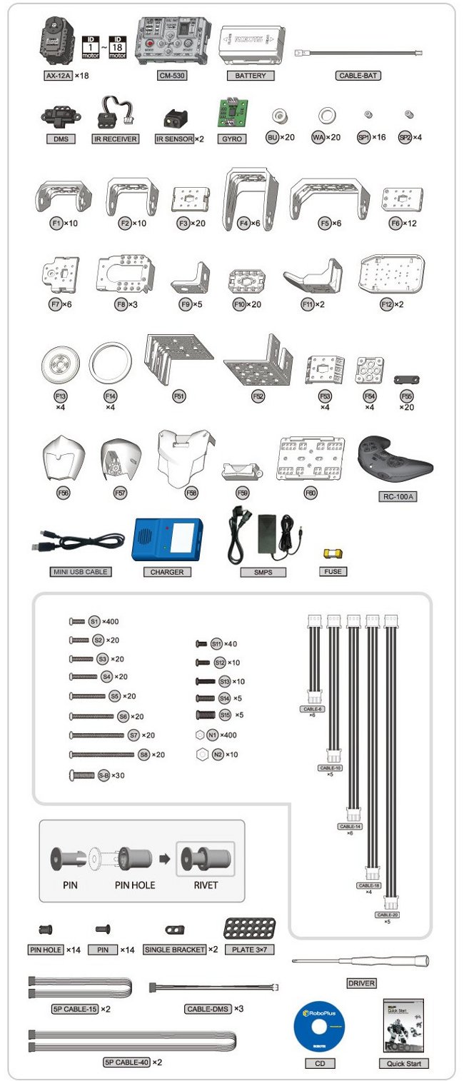
Part List
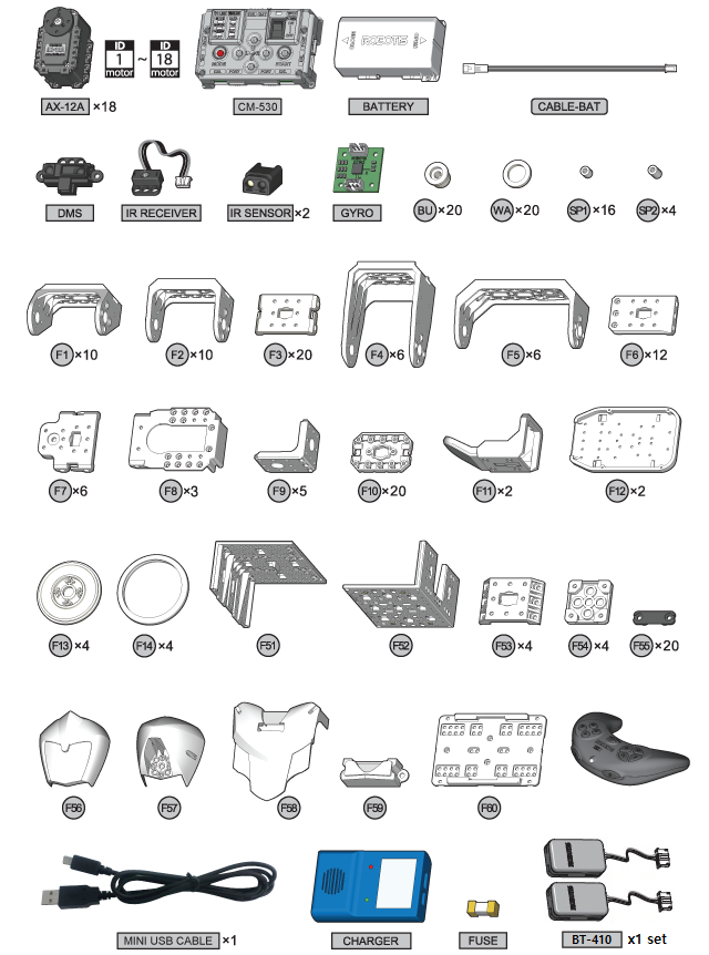
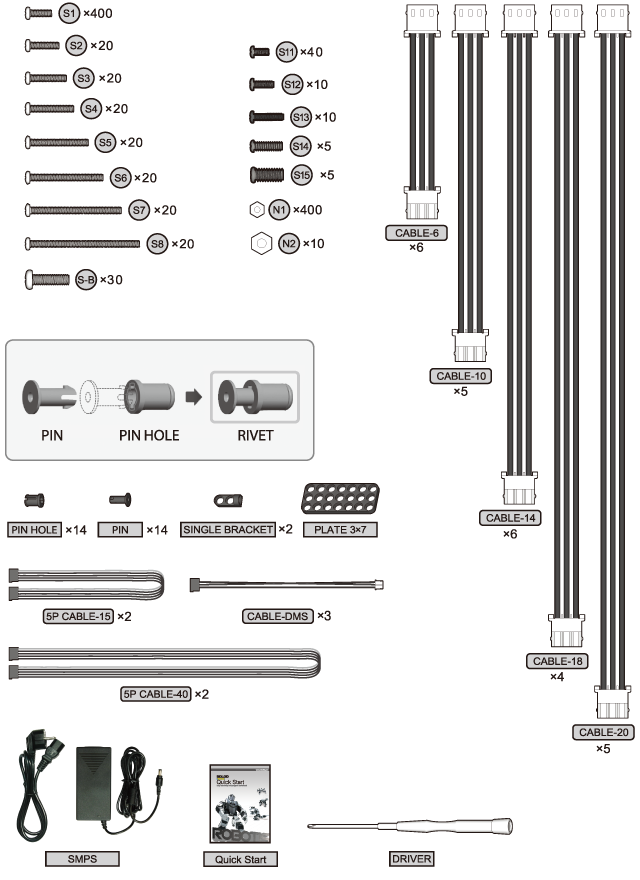
- CM-530
- AX-12A
- DMS Sensor
- IR Sensor
- Gyro Sensor
- USB2DYNAMIXEL
Operating
Downloading the Program
- Program for type A is installed by default in CM-530.
- You can find task codes and motion files for other actions on the Default Program page.
Turning the Robot on
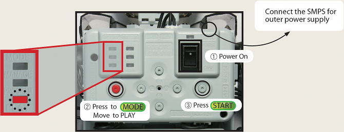
- Turn the power switch on and the LED will start blinking.
- Use the MODE button to move the LED to “PLAY”. (The LED will move each time you press the MODE button)
- Press the START button. (Check whether the LED on “PLAY” is blinking)
- If the LED does not turn on, check the power cable/connection.
- If there are no problems with cable, recharge your battery. (Please refer to Charging for more information)
The power does not turn on.
- Is the battery properly connected?
- Is the battery fully charged?
- Is the battery fuse intact?
- Please refer Fuse Replacement for information on how to replace the fuse.
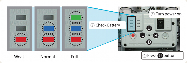
I want to check how much battery I have left.
Turn the CM-530 on and press the U button. The LED will turn on to show how much battery you have left as seen in the figure below.
The robot makes a continuous warning sound while moving.
- The alarm indicates that the robot is low on batteries. Immediately recharge your battery(Refer to Charge).
- If you do not replace the battery right away, the robot may turn off without warning and fall, which can cause severe damage.
Checking the robot’s basic posture (To check whether the robot has been assembled correctly)
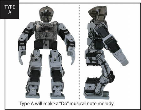
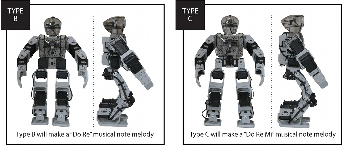
- The robot should stand in the basic stance and play a melody according to its type as in the picture below.
- Make sure to hold the robot in its basic posture for 1 minute.
This is to allow the robot to automatically configure its gyro sensors so that it can walk properly.
- Check the angles of the arms and legs. If they are different from the picture, go back to “Check Assembly Mode”
- Check whether the cables have been assembled on the outer part of the leg.
If the robot has been incorrectly assembled to an extent where it may be severely damaged, a warning sound will be activated. Also, the LED of the motor with the problem will turn on and release its torque to prevent damage.
The robot’s basic posture and movements are awkward.
- Awkward Basic Posture?
Go back to “Check Assembly Mode” and re-check whether all the dynamixels have been properly assembled.
- Unable to detect obstacles while in Free Walk Mode?
Check whether the absolute distance measurement sensor’s cables are properly in place.
The robot falls down easily while walking or is otherwise unstable.
- The gyro sensor used to detect the robot’s posture is not working
Please refer to the Assembly Manual to check whether the gyro sensor has been properly assembled.
The torque is released and the dynamixel’s LED turns on after a warning sound.
- If the motor and frames have not been properly assembled or if the robot’s joints can not move properly, a warning sound will be activated to prevent damage.
Find the motor indicated by the LED and refer to the Assembly Manual to check whether it has been assembled correctly.
Make sure that the joints are free of cables or other debris. Please refer to “Check Assembly Mode”
The robot type and melody do not match.
- Check whether the motors with ID 7 ~ 10 are assembled properly. Check for loose connections
| Robot Type | “Do” | “Do Re” | “Do Re Mi” | Repeat “Do Re Mi” |
|---|---|---|---|---|
| TYPE A | O(Correctly Assembled) | Check cables for ID 9~10 | Check cables for ID 7~8 | Some of the cables have not been connected properly. Please refer to the Assembly Manual and check again. |
| TYPE B | — | O(Correctly Assembled) | ID 9 and10 connected where ID 7 and 8 should be connected | Some of the cables have not been connected properly. Please refer to the Assembly Manual and check again. |
| TYPE C | — | ID 7 and 8 connected where ID 9 and 10 should be connected | O(Correctly Assembled) | Some of the cables have not been connected properly. Please refer to the Assembly Manual and check again. |
Robot in Action
R: Remote Control ModeD: Demo ModeL: Autonomous Walking ModeU: Check Assembly Mode
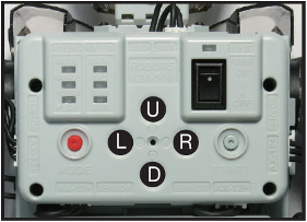
NOTE : If you press a button on RC-100 before choosing a mode, the robot will enter remote control mode.
Remote Control Mode
The RC-100 is used to control the robot.
- Press the POWER/MODE button for 2 seconds.
- Press the buttons below to control the robot.
- Walking : U / L / D / R
- Change Posture : 1 + U / L / D / R
- Demonstration Moves : 2 + U / L / D / R
- Soccer Moves : 3 + U / L / D / R
- Battle Moves : 4 + U / L / D / R
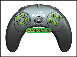
Walking Motions
| Buttons | Motion |
|---|---|
| U | Forward |
| D | Backward |
| L | Turn Left |
| R | Turn Right |
| U + L | Walk Forward + Left |
| D + L | Walk Left Sideways |
| U + R | Walk Forward + Right |
| D + R | Walk Right Sideways |
Change Postures
| Buttons | Motion |
|---|---|
| 1 + U | Getting up Backward (When lying on stomach) |
| 1 + D | Getting up Forward (When lying on back) |
| 1 + L | Push-up |
| 1 + R | Handstand |
| 2 + U | Pound Chest |
| 2 + D | Scratch Head |
| 2 + L | Cheer |
| 2 + R | Bow |
Soccer Motions
| Buttons | Motion |
|---|---|
| 3 + U | Block Right (Release button to return to normal position) |
| 3 + D | Block Left (Release button to return to normal position) |
| 3 + L | Shoot with left foot |
| 3 + R | Shoot with right foot |
Battle Motions
| Buttons | Motion |
|---|---|
| 4 + U | Attack |
| 4 + D | Defend (Release button to return to normal position) |
| 4 + L | Attack Left |
| 4 + R | Attack Right |
Setting the CM-530 IR Channels
After mounting the IR receiver on CM-530 under control mode, you can set the channels to control it remotely by pressing the Aux button. If you change the channel of the controller, you must also change the channel of RC-100. On how to change the channel of RC-100, please refer to Changing RC-100’s Channel.
| Buttons | Motion |
|---|---|
| Start + U | Set the RC-100 channel as 1 |
| Start + D | Set the RC-100 channel as 3 |
| Start + L | Set the RC-100 channel as 2 |
| Start + R | Set the RC-100 channel as 4 |
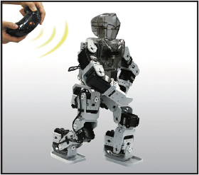
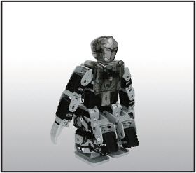
- If the robot does not receive commends for a period of time, it will standby in a seated position.
 |
 |
 |
|---|---|---|
| When being controlled | Seated in a standby position |
My remote controller does not work properly.
- Set to control mode.
- Check whether the IR receiver has been properly connected.
- Check whether the remote controller is on. Replace the battery and try again.
Point towards the IR receiver and try again.
Check if there are others controlling robots nearby, which may cause wireless interferences.
We want to play soccer or battle with several robots.
- In order to play a game with several users, you must install the ZIG-110 set.
- ZIG-110 set is available at the Robotis shopping mall.
- Please refer to Controller and RC-100 for installation information.
Demo Mode
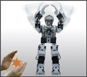
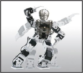
The robot will clap depending on how many times you clap.
When DMS senor detects an object, the robot greets the user.
If the robot does not sense any sound or object for a while, it performs various motions on its own.
 |
|
 |
|---|---|---|
| Claps depending on how many times you clap | Shows various movements |
Autonomous Walking Mode
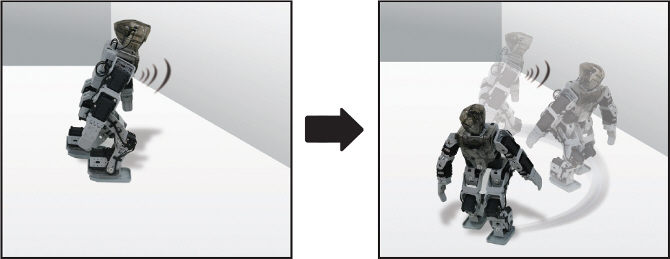
The robot will walk by itself while avoiding obstacles. When absolute distance sensor detects an obstacle, the robot will stop and turn left until the obstacle is no longer detected. If it falls down while walking, it will get back up in the direction it was moving.
Check Assembly Mode
You may use the Check Assembly Mode to see whether your robot has been properly assembled. Isolate each motor and compare it to the standard posture.
- Start the Check Assembly Mode. It will release the torque.
- Press the U or D button and check one motor at a time. The selected motor’s LED will turn on and move to its basic position. ( U : Increases the ID by 1, D : Decreases the ID by 1 )
- Check the ID of the motor with the LED and compare it with the ID in the Assembly Manual.
If the ID does not exist in the robot, a warning sound will be activated.
- Compare the position of the motors you have assembled to the basic posture.
If the LED is on but the torque is released, check the cables or the motor’s assembly status.
Battery Charge
You may obtain Lithium polymer batteries from www.robotis-shop-en.com.
If the robot alarm sounds off during operations then recharge the battery.
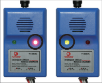
During charging the charger’s red LED turns on. When complete the green LED turns on.
-
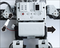
Take the battery out

-
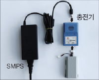
Connect the charger
-
Charge
Charging(Red LED), Complete(Green LED)
-
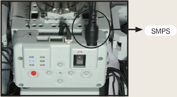
You can connect the robot to an external power source through SMPS.
-
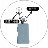
The battery is equipped with a connector to charge the battery and another to move the robot
Charging Time and Battery Life/Operating
Charging Time
- When fully discharged : 1~1.5 hour
- Leaving the battery fully discharged for too long may reduce its lifespan drastically.
- Time to charge the battery depends on the status of the battery(If the charging time or battery life becomes too short, you may need to replace your battery).
Caution
- Do NOT keep the battery connected with a robot or a charger.
- If you will not use the battery for a long time from now on, please keep it HALF-CHARGED.
- Do NOT put the battery with an environment with high temperature or humidity.
Tutorial
Screen Output
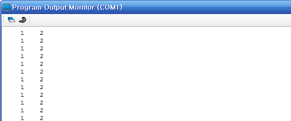
Objective for this tutorial is to print 1 and 2 on the output screen as below.
Write Task Code
-
Execute RoboPlus Task Program.
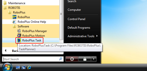
As seen in the picture below, go to
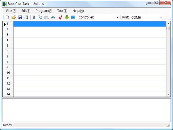
Start > All Programs > ROBOTIS > RoboPlus > Software > RoboPlus Taskto execute RoboPlus Task.- RoboPlus Task Initial Screen
-
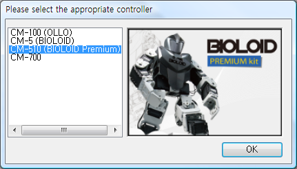
Select a Controller.
Double click an empty line or press
Enter, In theSelect Controlwindow, select the controller to use, then press theOKbutton. -
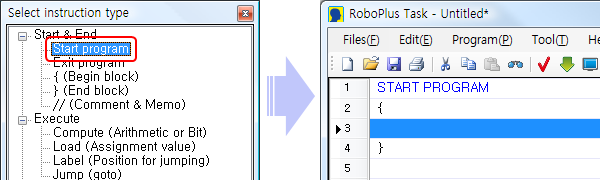
Generating
Start Program.Select
Start Programfrom theSelect Instruction Typewindow,Start Programwill be automatically generated in RoboPlus Task. -
Input
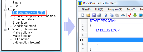
Endless LoopcommandTo print the numbers on the screen endlessly, use the
Endless Loopcommand(Create a command line).
Double click or pressEnteron an empty line between{and}of Start Program to invoke theSelect Instruction Typewindow. SelectLoop > Endless Loop(while(1))from the list. -
Input
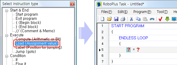
LoadcommandUse
Loadcommand to input aPrintcommand, which is needed to print numbers on the screen.
InsertExecute > Load (Assignment value)into an empty line between{and}ofEndless Loop. -
Load
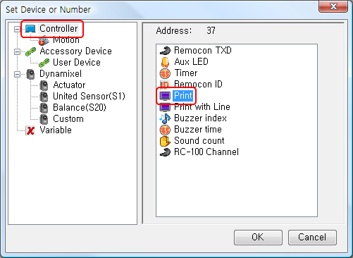
1intoPrintChoose the left parameter ( ? ) among the
Loadparameters(Explanation on the parameter).
The left parameter receives input from the right parameter.
Double click the left parameter ( ? ), or pressEnterkey after clicking it once to invoke theSelect Parameter Window.
SelectController > Printthen pressOK.Select
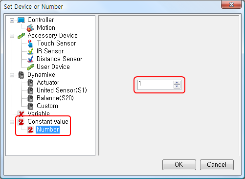
Constant Numbers > Number > 1for the right parameter ( ? ) in the same way.When both parameters of the
Loadcommand have been set, it should look like below. -
Load
2intoPrint with LineSelect
}underPrintcommand (at the end of the endless loop section), and add new lines by pressing theSpacekey. Repeat Steps 5 and 6 to input theLoadcommand and to inputController > Print with Lineand2. The final task code is shown below. -
Save Task Code
Press Ctrl + S or the Save icon.
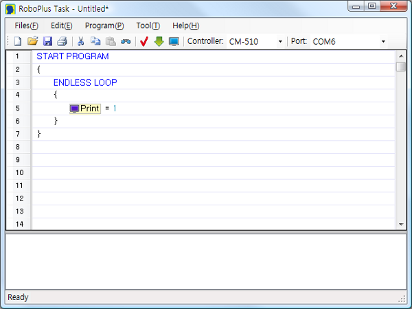
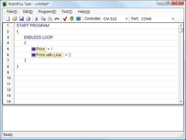
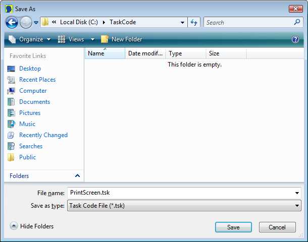
Download Task Code
Download the task code created above.(How to Download Task Code)
Execute Task Code
-
Open the Program Output Monitor
To see the output of the program, you must open the Program Output Monitor BEFORE executing the program.
There are three ways to open the Program Output Monitor.-
Click on the View Print of Program in the Download Program window
- Click on the
View Print of Programbutton in TOOLS. - Press
F5or click on View Print of Program (V) menu under Program (P).
-
-
Executing the Program
When you turn on the controller, the LED will blink, showing it is in standby mode.
Press the MODE button to move it to PLAY, then press START to execute the downloaded task code.
You should see “1” and “2” being printed on the Program Output Monitor.
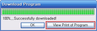
Button & LED
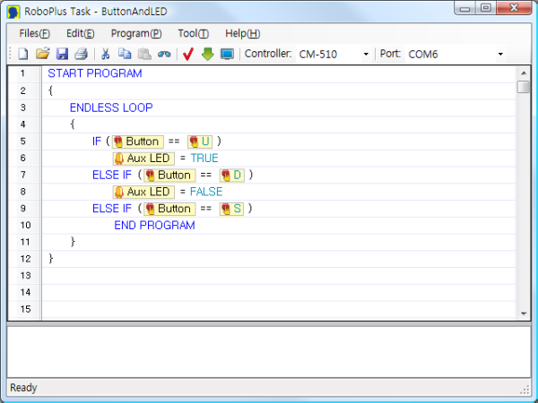
Objective for this tutorial is to program the U button to turn the AUX LED on and the D button to turn it off. Pressing the START button will end the program.
Write Task Code
Download Task Code
Download the task code created above.(How to Download Task Code)
Execute Task Code
Execute the program and check whether the AUX LED turns on when you press the U button and turns off when you press the D button. Press START button to end.
Walking Machine
Objective for this tutorial is to learn how to use the Walking Machine.
Waking Machine is a combination of a walking motion file made up of specific patterns and a task code that plays theh role of smoothly connecting the walking motions in this motion file.
- Download Walking Motion File
- Download Walking Task Code
Let’s use the Walking Machine to learn about how walking motions are converted smoothly.
Motion File Overview
Walking Motion File
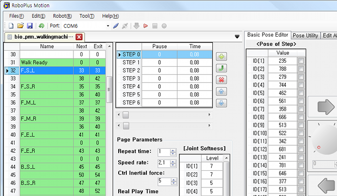
The walking motion files used in the Walking Machine can be found on pages 31~224. Several motion pages are gathered and repeatedly played to make up one walking pattern (forward, backward, etc). Each page is made to be conveniently converted to the next walking pattern’s motion page.
The walking patterns written in the Walking Motion File
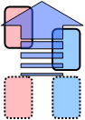
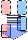
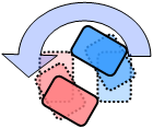
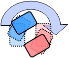
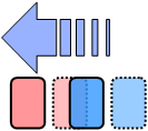
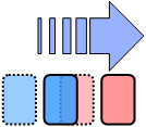
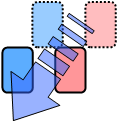
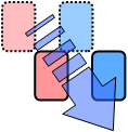
The walking motion files used in the Walking Machine contain 16 different walking patterns shown below.
| Forward | Backward | Left Turn | Right Turn |
|---|---|---|---|
 |
 |
 |
 |
| Walk Sideways + Left | Walk Sideways + Right | Turn Left + Forward | Turn Right + Forward |
|---|---|---|---|
 |
 |
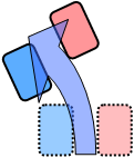 |
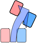 |
| Backward + Left | Backward + Right | Avoid Left | Avoid Right |
|---|---|---|---|
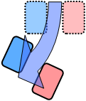 |
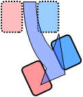 |
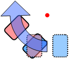 |
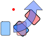 |
| Forward + Left Diagonally | Forward + Right Diagonally | Backward + Left Diagonally | Backward + Right Diagonally |
|---|---|---|---|
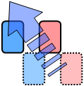 |
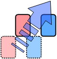 |
 |
 |
Task Code Overview
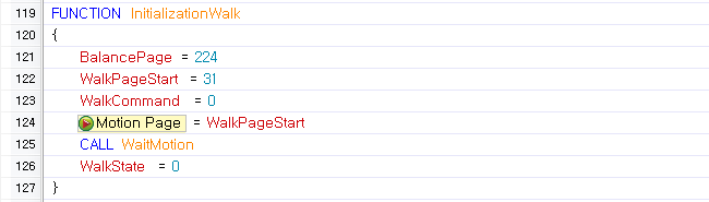
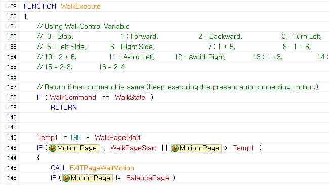
The walking machine task code includes a InitializationWalk Function and a WalkExecute function. There are samples that use these 2 functions to control the robot with a remote controller.
InitializationWalk Function
The InitializationWalk function initializes the variables and brings the robot to its default position.
WalkExecute Function
The WalkExecute function executes each walking pattern and smoothly joins the walking pattern.
Walk Command No.
| No. | Walking Pattern | No. | Walking Pattern | No. | Walking Pattern | No. | Walking Pattern |
|---|---|---|---|---|---|---|---|
| 1 | Forward | 2 | Backward | 3 | Left Turn | 4 | Right Turn |
| 5 | Walk Sideways + Left | 6 | Walk Sideways + Right | 7 | Turn Left + Forward | 8 | Turn Right + Forward |
| 9 | Backward + Left | 10 | Backward + Right | 11 | Avoid Left | 12 | Avoid Right |
| 13 | Forward + Left Diagonally | 14 | Forward + Right Diagonally | 15 | Backward + Left Diagonally | 16 | Backward + Right Diagonally |
Start Program
Let’s try writing a simple “Start Program” sample using the “InitializationWalk” function and “WalkExecute” functions to smoothly connect walking patterns.
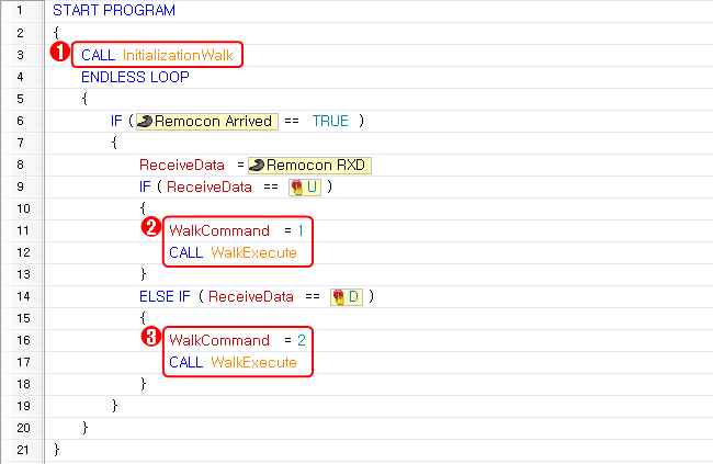
- First, call the
InitializationWalkfunction to initialize the variable and to bring the robot to its default position. - Select and input a walking pattern between 0 and 16 for the
WalkCommandvariable, then call theWalkExecutefunction to run the selected walking pattern. - When you input a different number in the
WalkCommandvariable and call theWalkExecutefunction, it will convert to the new walking pattern as naturally as possible.
There are 16 different walking pattern sample codes to control via remote control in the walking machine’s task code file. Change the Start Program function in the sample codes to suit your needs.
Gyro Sensor Calibration
- Prerequisite : Walking Machine
Code to control the gyro sensor will be added to the task code used in the [Walking Machine] section. Review the [Walking Machine] section before getting started.
Objective for this tutorial is to learn how to adjust a humanoid’s posture using a gyro sensor.
A Gyro sensor is used to determine angular velocity (angular variation per second). When the robot tilts and angular velocity increases in a specific direction, the servo motor’s value can be adjusted in the opposite direction to straighten the robot.
Download TASK Code(BIO_PRM_GyroSensorExam_EN.tsk)
Things to Prepare
- The gyro sensor’s X-axis value should be connected to port #3, and Y-axis value should be connected to port #4.
- Other than that, modify the task code to suit your robot.
Concept
-
Callback Function
A humanoid with a gyro uses the Callback Function to determin the posture adjustment value.
The callback function is a function that runs independently of the main program routine and is automatically executed at fixed intervals. Therefore, by calculating the adjustment value and using the value in a callback function to adjust the posture at regular intervals, the robot can adjust its posture automatically.
-
Joint Offset
The joint off set is added to the adjustment value from the gyro sensor before being used to adjust the humanoid’s posture. (More information on Joint Offset) This is a parameter that gives an offset to the specific actuator’s joint position value. Thus, the actuator with joint offset execute their motions using the position value + joint offset value, which are designated in the motion file.
Task Code Overview
InitializationGyroCall Function
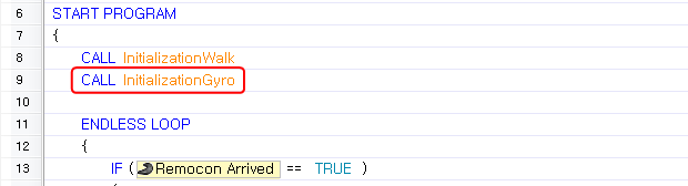
- Execute
BalancePageto Apply Joint Offset
In order to apply the joint offset a motion must be executed. When no motion is being played, the joint offset will not be applied even if a value is input by the gyro sensor. The BalancePage is used to apply the joint when no motion is being executed.

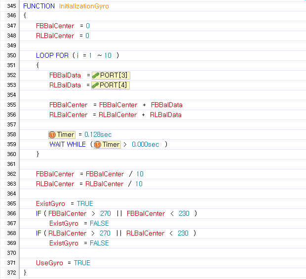
InitializationGyroFunction
The InitializeGyro function reads the gyro sensor value 10 times in a 0.128 second intervals and saves the average value as a gyro sensor standard value. (The standard value is Approximate 250 degrees.) If the gyro sensor value is less than 230 or greater than 270, it assumes there is no gyro sensor and does not use adjustment (when there is no gyro sensor or the robot has moved during initialization).
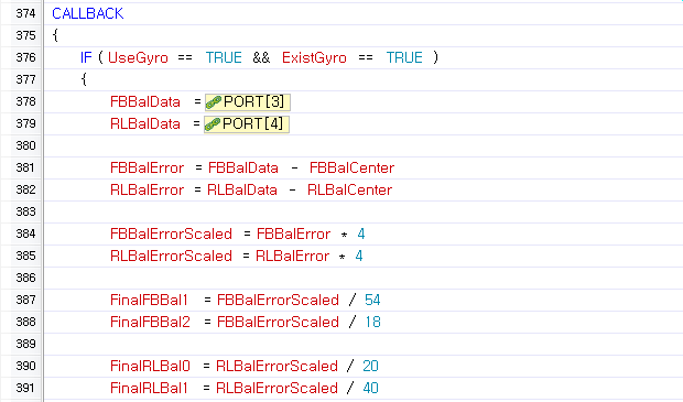
- Calculating the adjustment value in the
Callback Function
At regular intervals, the callback function reads the current gyro sensor value and compares it to the standard value to calculate the adjustment value. If the UseGyro variable is false, the robot it will not adjust itself. Thus, set the UseGyro variable to false where you do not wish to use the gyro adjustment.
Apply the calculated adjustment value to the joint offset and adjust the robot’s posture. To adjust the front/back tilt, you must use the joints in the knees and ankle, which are actuators 13-16. To adjust the left/right tilt, you must use the joints in the ankle and waist, which are actuators 9-10 and 17-18.
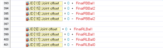
Adjustment Test
- Download the task code to your robot(How to Download Task Code).
- In order to initialize the gyro, you must leave your robot on flat ground for at least 1.5 seconds after executing the task code. If the gyro sensor is not connected or if there is movement while initializing the gyro, the gyro will not make any adjustments.
- Check whether the robot attempts to adjust itself when its posture is changed by a strong outside force while standing straight.
- Compare the robot’s actions when it uses and does not use a gyro while stanind on a slope.
Custom Motions(Create)
Prerequisite : [Walking Machine]
Motions will be added to the motion file used in the “Walking Machine” section. Review the “Walking Machine” section before getting started.
Objective for this tutorial is to add a new motion using RoboPlus Motion.
Let’s learn how to add 4 motions below using the RoboPlus Motion program.
| Motion Page No | Movement Description | Motion Page No | Movement Description |
|---|---|---|---|
| 14 | Block ball on the right | 27 | Get up while lying on stomach |
| 16 | Block ball on the left | 28 | Get up while lying on back |
Download Motion File(BIO_PRM_UserMotionExam_EN.mtn)
Make a motion to block a ball on the right
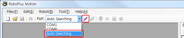
- Execute RoboPlus Motion, then connect it to the controller(Please refer to Connect Robot)
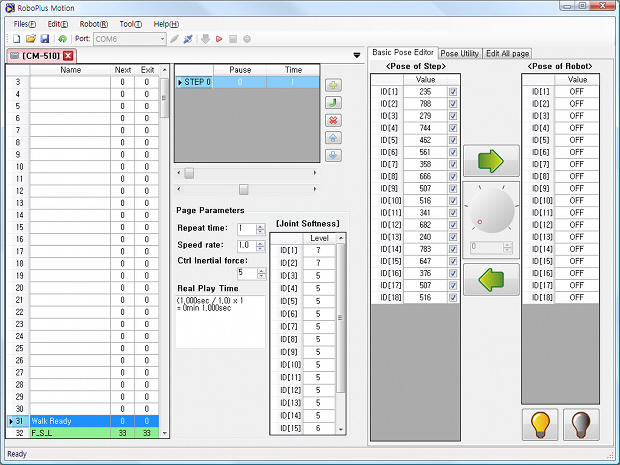
- To add the “Block Ball” motion in page 14, input a name and step.

- Turn off all motors, then set the robot’s pose. The “Block ball on the right” pose is shown below.
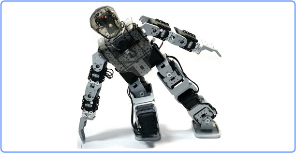
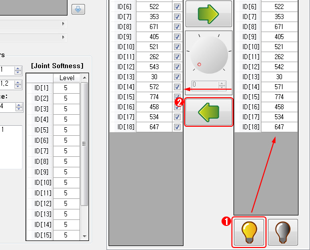
- Set the robot’s pose as above. When you press the “torque on” button, the robot’s current actuator values will automatically be saved. When you press the left arrow button, you can read the robot’s current input actuator values into Step’s Pose column.
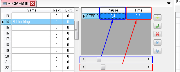
- You can adjust the pause and play durations. (Please refer for more information about STEP STOP/PLAY)
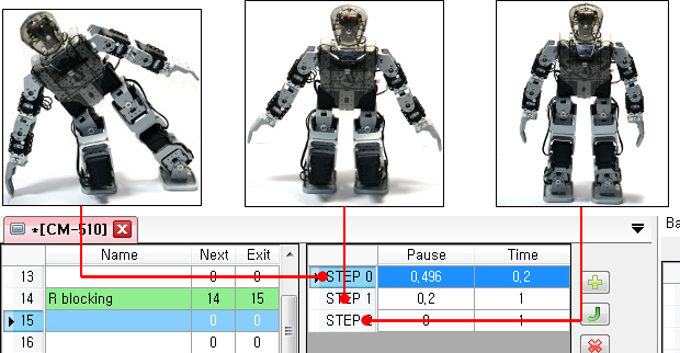
- Designating the NEXT page as itself(14) will cause the robot to enter an infinite loop and maintain its pose. Also designate an EXIT page for the robot to smoothly transiton into when it exits the infinite loop.

- Make a motion to return to the standard position on the page designated as the Exit page (15). Add the following 3 steps and poses to page 15.
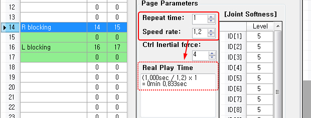
- Additional settings (Number of Repeats, Play Speed, etc)
You can also set the number of repeats, entire speed, etc. for each page.
Make a motion to block a ball on the left
Repeat STEP 1 to make a motion to block a ball on the left on pages 16 and 17.
Make motions to get up when the robot lying on its back and chest.
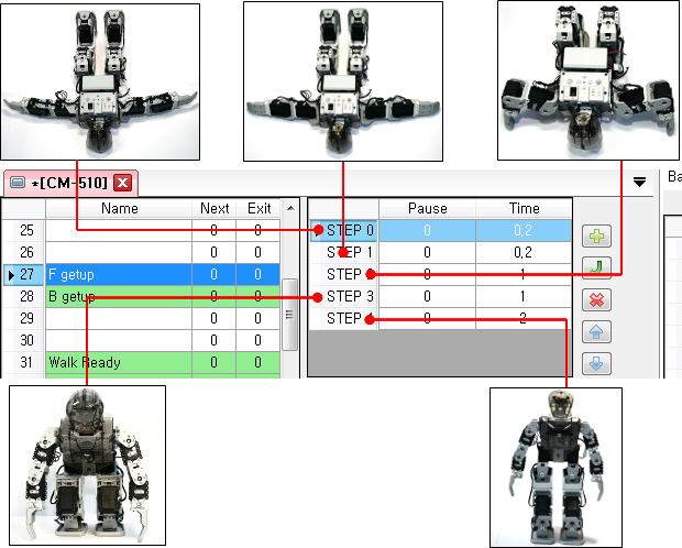
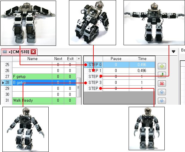
Add the following steps in motion page 27 and 28 to make a “Get up while lying on stomach” and “Get up while lying on back” motions.
-
Get up while lying on the stomach
-
Get up while lying on the back
Save
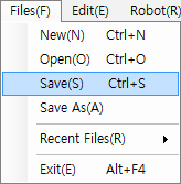
Use the Save(S) command to save your work in the robot or use Save As(A) to save as a .mtn file in your PC.
Custom Motions(Task Code)
Prerequisite : Adjustment using the Gyro Sensor, Custom Motions: Create
Code to execute user-defined motions will be added to the task code used in the Adjustment using the Gyro Sensor section. The motion file is from the Custom Motions: Create section. Review the two sections before getting started.
Write task code to execute user-defined motions.
Let’s learn how to run the motion added on “ User-defined Motions 1 : Create Motion “ with the RC-100.
- Download Motion File(BIO_PRM_UserMotionExam_KR.mtn)
- Download TASK Code(BIO_PRM_UserMotionExam_KR.tsk)
Task Code Overview
Code to execute user-defined motions has been added to the task code written in “Adjusting using the Gyro Sensor.”
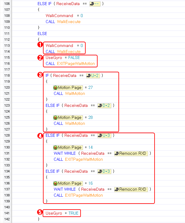
- Set
WalkCommandas 0 to make the robot stop. - If the motion added by the user does not require the gyro sensor to maintain posture, you must turn off the gyro sensor adjustment to prevent motion variation due to the offset. Set the
UseGyrovariable as FALSE. Then call theEXITPageWaitMotionfunction and wait for the robot to come to a complete stop. - The
Getting Upmotions added in motion pages 27 and 28 can be played just once. Thus, execute the motion, and wait for the motion to finish before executing another motion. - The
Block Ballmotions added in motion page 14 and 16 are endlessly repeating motions. Thus, in order to end the motion, an EXIT page is needed. Using theWAIT WHILEcommand so that if the button is not pressed and held, theEXITPageWaitMotionfunction will execute the EXIT to end the motion
(For more information, please refer to the Motion Page). - After the user’s motion ends, set the
UseGyrovariable back to TRUE to restore gyro adjustment.
Gripper Control
Prerequisite : Custom Motions: Create, Custom Motions: Task Code
Review the two sections before getting started.
Objective for this tutorial is to learn how to control the grippers regardless of the motions.
When you add a gripper to your robot, there is a need to keep the robot’s arm fixed regardless of the motion.
In this case, it is not necessary to revise the motions to keep the arm still. Instead, let’s learn to control the gripper using the task code, while preventing specific actuators from being controlled by the motion data.
- Download Motion File(BIO_PRM_HumanoidTypeB_EN.mtn)
- Download TASK Code(BIO_PRM_GripperExam_EN.tsk)
Background Knowledge
Setting priorities to control the gripper and motions separately.
-
Normal Control Priorities
Normally, motion data has the highest priority and task code has the next highest priority. Thus, under normal circumstances, if a motion is executed, it is impossible to control specific dyanmixels using task code.
-
Changing Control Priorities
There are 2 methods to control the motor (entire arm including the gripper) with a task code while a motion is being executed.
- Uncheck the “Using Now/Not Using” checkbox for the acutator’s ID in the motion data.
- Set the actuator’s “Joint Offset” parameter to 1024.
The first method disables the actuator in the entire page. Even If there is a motion requiring the corresponding actuator, there is no way to control it with the motion data. Therefore, the second method, which allows you to activate /deactivate the application of the motion data for the specific actuator depending on your needs, may be the better option.
Assembly
Please refer to the [Gripper Assembly].
Writing Task Code
- Initializing Gripper Control
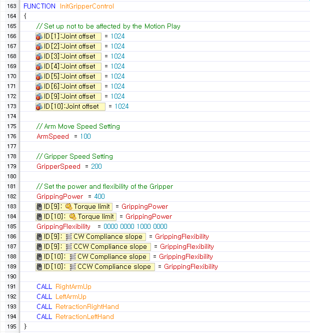
Set the joint offsets of the actuatorsfor both arms to 1024, so that they are not controlled by the motion data. Initialize the other data , such as the arms’ and grippers’ movement speeds, and gripper’s grasping power and flexibility, then place the arms in their default position.
- Revise Callback Function (Gyro Adjustment)
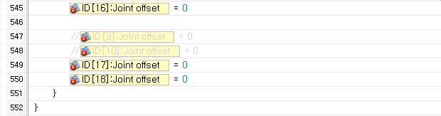
If the joint offset is used in the callback function to apply the gyro adjustment value, the joint offset should not be set for the joints used by the grippers. This is to prevent the values set as 1024 in STEP 1 from being changed.
- Gripper/Arm Control Function
Copy the following fuction to control the gripper and arm. This function can control the gripper’s and arm’s movements, regardless of the motion status.
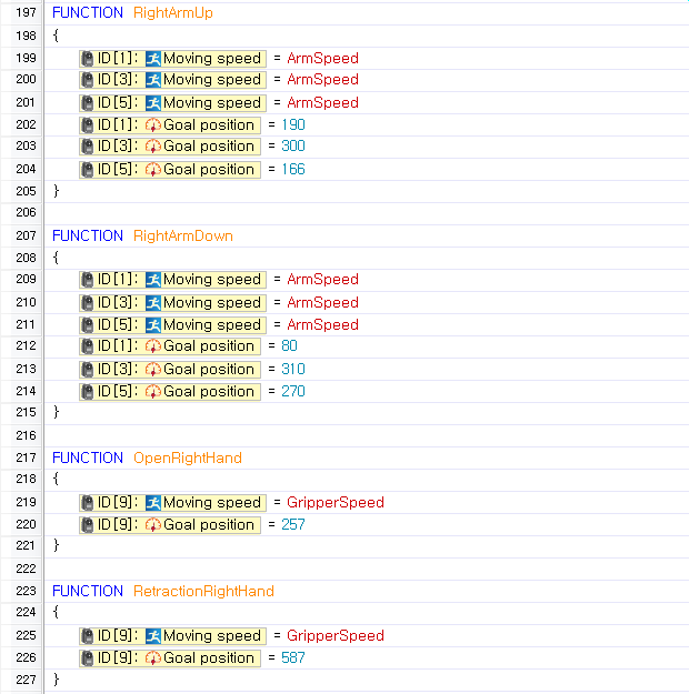
Write a function for the left arm and gripper as above.
- Controlling the arm and gripper with a remote controller
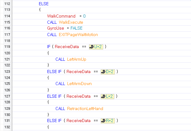
Add code to control the gripper and arm using the remote controller. Reviewing [Custom Motions: Task Code] will help you understand the code below.
Download and Verify Result
- Download the task code written in STEP 2 (How to Download of task code).
- While controlling the robot’s motion with the remote controller, check whether the gripper and arm are fixed.
- Control the gripper with the remote controller.
Download
Default Program
- How to Download of task code
- How to Download motion file
| Robot Type | File Type | Download |
|---|---|---|
| Assembly Manual | PDF File | Download |
| A Type | Task Code | Download |
| A Type | Motion File | Download |
| B Type | Task Code | Download |
| B Type | Motion File | Download |
| C Type | Task Code | Download |
| C Type | Motion File | Download |
Humanoid Fight
| Robot Type | File Type | Download |
|---|---|---|
| A Type | Humanoid Fight Task Code | Download |
| A Type | Humanoid Fight Motion File | Download |
Walking
| Buttons | Motion | Buttons | Motion |
|---|---|---|---|
| U | Move Forward | D | Move Backward |
| L | Turn Left | R | Turn Right |
| U + L | Move Forward and Turn Left | U + R | Move Forward and Turn Right |
| L + 5 | Move Leftward | L + 5 + 6 | Move Leftward Quickly |
| L + U + 5 | Move Forward and Leftward | L + D + 5 | Move Backward and Leftward |
| R + 5 | Move Rightward | R + 5 + 6 | Move Rightward Quickly |
| R + U + 5 | Move Forward and Rightward | R + D + 5 | Move Backward and Rightward |
Attack
| Buttons | Motion | Buttons | Motion |
|---|---|---|---|
| 1 + L | Attack Diagonal Left | 6 + 2 | Strong Left Attack |
| 1 + R | Attack Diagonal Right | 6 + 4 | Strong Right Attack |
| 2 + U | Attack Front | 6 + 1 | Strong Front Attack |
| 2 + L | Attack Left | 4 + U(4 + L) | Grab 1 |
| 2 + R | Attack Right | 4 + D(4 + R) | Grab 2 |
| 3 | Attack Left and Right | — | — |
ETC
| Buttons | Motion | Buttons | Motion |
|---|---|---|---|
| 5+6+D+3 | Torque Off | 5+6+U+1 | Torque On |
| 1 + U | Stand Up from face down | 1 + D | Stand Up from back down |
Humanoid Soccer
| Robot Type | File Type | Download |
|---|---|---|
| A Type | Humanoid Soccer Task Code | Download |
| A Type | Humanoid Soccer Motion File | Download |
Walking
| Buttons | Motion | Buttons | Motion |
|---|---|---|---|
| U | Move Forward | D | Move Backward |
| L | Turn Left | R | Turn Right |
| U + L | Move Forward and Turn Left | U + R | Move Forward and Turn Right |
| L + 5 | Move Leftward | L + 5 + 6 | Move Leftward Quickly |
| L + U + 5 | Move Forward and Leftward | L + D + 5 | Move Backward and Leftward |
| R + 5 | Move Rightward | R + 5 + 6 | Move Rightward Quickly |
| R + U + 5 | Move Forward and Rightward | R + D + 5 | Move Backward and Rightward |
Offense
| Buttons | Motion | Buttons | Motion |
|---|---|---|---|
| 2 + U | Left Kick Forward | 4 + U | Right Kick Forward |
| 2 + 6 + U | Strong Left Kick Forward | 4 + 6 + U | Strong Right Kick Forward |
| 2 + D | Kick Backward | 4 + D | Kick Backward |
| 2 + L | Kick Left | 4 + L | Kick Left |
| 2 + R | Kick Right | 4 + R | Kick Right |
Defense
| Buttons | Motion | Buttons | Motion |
|---|---|---|---|
| 3 | Prepare for Blocking | 3 + L | Block Left |
| 3 + U | Block Front | 3 + R | Block Right |
ETC
| Buttons | Motion | Buttons | Motion |
|---|---|---|---|
| 5+6+D+3 | Torque Off | 5+6+U+1 | Torque On |
| 1 + U | Stand Up from face down | 1 + D | Stand Up from back down |
| 1 + L | Chest Beat | 1 + R | Cheer |
Examples
Beginner
| Examples | Description |
|---|---|
1. Crossing Gate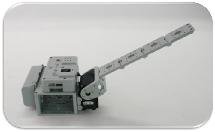 |
Download Assembly Manual Download Task Code Download Video Devices CM-530(x1), AX-12+(x1)DYNAMIXEL Setting AX-12+ ID[1]: Joint ModeRoboPlus Language Function, Call, Load, Endless Loop, If, Wait WhileAlgorithm Control DYNAMIXEL’s position using the buttons on the CM-530Operation Guide— Press the U button on the CM-530 to open the bar.— Press the D button on the CM-530 to lower the bar. |
2. Universal Gauge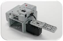 |
Download Assembly Manual Download Task Code Download Video Devices CM-530(x1), AX-12+(x1)DYNAMIXEL Setting: AX-12+ ID[1]: Joint ModeRoboPlus Language Function, Call, Return, Load, Calculate, Endless Loop, If, Else ifAlgorithm Control DYNAMIXEL’s speed using the buttons on the CM-530Operation Guide— Press the U button on the CM-530 to increase the gauge’s speed.— Press the D button on the CM-530 to decrease the gauge’s speed. |
3. Crocodile Mouth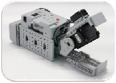 |
Download Assembly Manual Download Task Code Download Video Devices CM-530(x1), AX-12+(x1), IR Sensor(x1)DYNAMIXEL Setting: AX-12+ ID[1]: Joint ModeRoboPlus Language Function, Call, Load, Endless Loop, If, Else If, Wait WhileAlgorithm Control DYNAMIXEL position and Buzzer with the value from the IR Sensor and TimerOperation Guide— The mouth opens when the front sensor detects something, and close when nothing is detected. — It will open its mouth when it detects something. — A melody will activate if nothing is detected for 10 seconds. |
4. Pan Tilt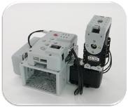 |
Download Assembly Manual Download Task Code Download Video Devices CM-530(x1), AX-12+(x2)DYNAMIXEL Setting: AX-12+ ID[1, 2]: Joint ModeRoboPlus Language Function, Call, Load, Calculate,Endless Loop,If, Else If, Wait WhileAlgorithm Control the Pan Tilt using the buttons on the CM-530Operation Guide— Press the U button on the CM-530 to move the tilt actuator (Up, Down) up.— Press the D button on the CM-530 to move the tilt actuator (Up, Down) down.— Press the R button on the CM-530 to turn the pan actuator (Sideways) right.— Press the L button on the CM-530 to turn the pan actuator (Sideways) left. |
5. Parking Gate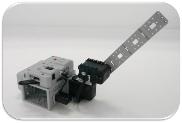 |
Download Assembly Manual Download Task Code Download Video Devices CM-530(x1), AX-12+(x2), IR Sensor(x1)DYNAMIXEL Setting: AX-12+ ID[1, 2]: Joint ModeRoboPlus Language Function, Call, Load, Endless Loop, If, Else If, Wait While, Break LoopAlgorithm Control DYNAMIXEL’s position using the IR Sensor and DYNAMIXEL’s load value.Operation Guide— When an object is detected, the parking gate opens perpendicularly. — When an object is detected and the bar is pushed, the parking gate opens horizontally. — When an object is not detected, the parking gate closes. |
6. Smart Car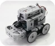 |
Download Assembly Manual Download Task Code Download Video Devices CM-530(x1), AX-12+(x4), IR sensor(x2)DYNAMIXEL Setting: AX-12+ ID[1 ~ 4]: Wheel ModeRoboPlus Language Function, Call, Load, Calculate, Jump, Lable, Endless Loop, If, Else If, Wait WhileAlgorithm Use the CM-530’s buttons to set the mode and use the buttons and sensor value to control the rotation direction.Operation Guide— Press the U button together with the START button on the CM-530 to change to CONTROL mode.— Press the D button together with the START button on the CM-530 to change to FREE mode.— When you press the L button in CONTROL mode, it moves forward. The R button moves backward, U button moves rights, and the D button moves left. A melody will play each time it moves.— When front sensor detects an object in FREE mode, it will turn right. When the lower sensor detects something, it will avoid the edge and turn right. |
7. Clapping Crab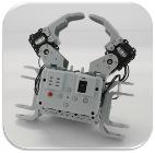 |
Download Assembly Manual Download Task Code Download Video Devices CM-530(x1), AX-12+(x2)DYNAMIXEL Setting: AX-12+ ID[1, 2]: Joint ModeRoboPlus Language Load, Calculate, Endless Loop, If, Wait WhileAlgorithm Control DYNAMIXEL position using the number of times the MIC detects a sound.Operation Guide— The robot will standby with its arm open. — The robot the number of time it detects a sound. |
8. Attacking Duck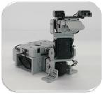 |
Download Assembly Manual Download Task Code Download Video Devices CM-530(x1), AX-12+(x3), IR Sensor(x2)DYNAMIXEL Setting: AX-12+ ID[1, 2, 3]: Joint ModeRoboPlus Language Function, Call, Load, Endless Loop, If, Loop While, Wait WhileAlgorithm Use the sensor detecting to control DYNAMIXEL’sOperation Guide— The robot moves sideways continuously and watches for objects. — The robot follows the direction in which an object is detected then attacks when both sensors detect an object. |
9. Distance Level Meter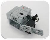 |
Download Assembly Manual Download Task Code Download Video Devices CM-530(x1), AX-12+(x1), DMS Sensor(x1)DYNAMIXEL Setting: AX-12+ ID[1]: Joint ModeRoboPlus Language Function, Call, Load, Calculate, Endless LoopAlgorithm Control DYNAMIXEL position using the distance detected by the sensor.Operation Guide The bar moves depending on the distance detected by the sensor. |
10. Line Tracer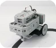 |
Download Assembly Manual Download Task Code Download Video Devices CM-530(x1), AX-12+(x2), IR Sensor(x2)DYNAMIXEL Setting: AX-12+ ID[1, 2]: Wheel ModeRoboPlus Language Function, Call, Load, Calculate, Endless Loop, If, Else If, Else, Wait WhileAlgorithm Control the line tracer using the sensor’s detection value.Operation Guide The robot traces the black line. |
11. Walking Droid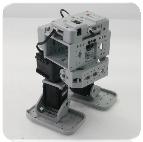 |
Download Assembly Manual Download Task Code Download Motion File Download Video Devices CM-530(x1), AX-12+(x4), IR Sensor(x1)DYNAMIXEL Setting: AX-12+ ID[1 ~ 4]: Joint ModeRoboPlus Language Function, Call, Load, Endless Loop, If, Loop While, Wait WhileAlgorithm Control various motions using the IR Sensor’s value.Operation Guide— Place an object in the robot’s path and start your robot. — Checks whether the robot avoids obstacles while walking. |
Intermediate
| Examples | Description |
|---|---|
1. Probing Robot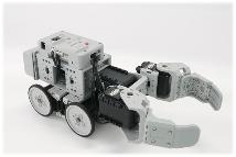 |
Download Assembly Manual Download Task Code Download Video Devices CM-530(1), AX-12+(7),IR Sensor(1), DMS Sensor(1)DYNAMIXEL Setting AX-12+ ID[1~4] : Wheel Mode, AX-12+ ID[5~7] : Joint ModeRoboPlus Language Function, Call, Return, Load, Calculate, Endless Loop, If, Else, Wait While, Break LoopAlgorithm Object sensing and processing depending on IR Sensor’s and DMS Sensor’s valueOperation Guide— Place objects of various sizes in the robot’s path, then turn the robot on. — If the obstacle is too big, it will avoid it. — If the obstacle is not too big, it will move it then proceed going its way. |
2. Excavator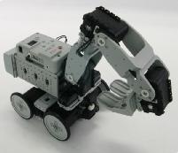 |
Download Assembly Manual Download Task Code Download Motion File Download Video Devices CM-530(1), AX-12+(8), IR Sensor(1), DMS Sensor(1)DYNAMIXEL Setting AX-12+ ID[1~4] : Wheel Mode, AX-12+ ID[5~8] : Joint ModeRoboPlus Language Function, Call, Load, Calculate, Endless Loop, If, Else, Wait WhileAlgorithm DYNAMIXEL Position control depending on IR Sensor’s and DMS Sensor’s value.Operation Guide— Place an object in the robot’s path, then turn the robot on. — When an object is detected in front of it, it will begin excavating. — If an object is detected while carrying an object, the robot will turn in that direction and put the object it was carrying down. |
3. Robot Flower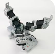 |
Download Assembly Manual Download Task Code Download Motion File Download Video Devices CM-530(1)(Sound Detection), AX-12+(6)DYNAMIXEL Setting AX-12+ ID[1~6] : Joint ModeRoboPlus Language Function, Call, Load,Endless Loop, If, Else, Wait WhileAlgorithm Motion control depending on the number of time sound is detected.Operation Guide— When the power is turned on, the flower blooms and moves as though it is dancing. — If one clap is detected, the petals will pucker up slowly. — If several claps are detected, the petals will pucker up quickly. |
4. Fawn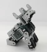 |
Download Assembly Manual Download Task Code Download Motion File Download Video Devices CM-530(1)(Sound Detection), AX-12+(7), IR Sensor(1)DYNAMIXEL Setting AX-12+ ID[1~7] : Joint ModeRoboPlus Language Function, Call, Load, Endless Loop, If, Else If, Else, Wait WhileAlgorithm Object sensing using IR Sensor’s value.Operation Guide— When no change is detected, the fawn sits down and looks around. — If an object is detected in front of the face, the fawn will follow the object. |
5. Turtle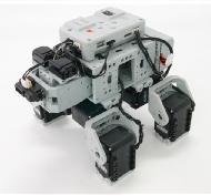 |
Download Assembly Manual Download Task Code Download Motion File Download Video Devices CM-530(1), AX-12+(8), IR Sensor(2), DMS Sensor(1)DYNAMIXEL Setting AX-12+ ID[1~8] : Joint ModeRoboPlus Language Function, Call, Load, Endless Loop, If, Else If, Else, Wait WhileAlgorithm Avoids obstacles depending on the IR Sensor and DMS Sensor value.Operation Guide— Place an obstacle in the robots path and turn the robot on. — The turtle avoids obstacles in front of it. |
6. GerWalk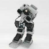 |
Download Assembly Manual Download Task Code Download Motion File Download Video Devices CM-530(1), AX-12+(7), IR Sensor(2), DMS Sensor(1)DYNAMIXEL Setting AX-12+ ID[1~7] : Joint ModeRoboPlus Language Function, Call, Load, Endless Loop, If, Else If, Else, Loop WhileAlgorithm Control the Bird’s walking pattern using the IR Sensor and DMS Sensor value.Operation Guide— Place an obstacle in the robots path and turn the gerwalk robot on. — The robot avoids obstacles in front of it and on the sides. |
7. Battle Droid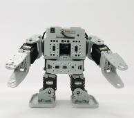 |
Download Assembly Manual Download Task Code Download Motion File Download Video Devices CM-530(1), AX-12+(8), IR Sensor(1)DYNAMIXEL Setting AX-12+ ID[1~8] : Joint ModeRoboPlus Language Variables, Function, Call, Load, Calculate, Endless Loop, If, Else If, Else, Wait WhileAlgorithm DYNAMIXEL control using the IR Sensor’s valueOperation Guide— Place an obstacle in the robots path and turn the battle droid robot on. — When the robot detects an object while walking, it will attack with both arms. — When battle droid falls down, it will know which side it has fallen up and get up on its own. |
8. Quadruped Robot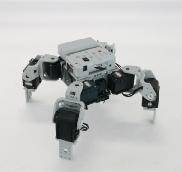 |
Download Assembly Manual Download Task Code Download Motion File Download Video Devices CM-530(1), AX-12+(8), IR Sensor(1), DMS Sensor(1)DYNAMIXEL Setting AX-12+ ID[1~8] : Joint ModeRoboPlus Language Function, Call, Load, Endless Loop, If, Wait WhileAlgorithm Control the walking using the IR Sensor and DMS Sensor valueOperation Guide— Place an obstacle in the robots path and turn the quadruped robot on. — The robot avoids obstacles in front of it. |
9. Biped Walking Robot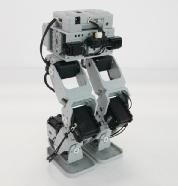 |
Download Assembly Manual Download Task Code Download Motion File Download Video Devices CM-530(1), AX-12+(8), IR Sensor(1), DMS Sensor(1)DYNAMIXEL Setting AX-12+ ID[11~18] : Joint ModeRoboPlus Language Function, Call, Load, Endless Loop, If, Else If, Else, Wait While, Loop WhileAlgorithm Control the walking using the IR Sensor and DMS Sensor valueOperation Guide— Place an obstacle in the robots path and turn the robot on. — The robot avoids obstacles in front of it and on the sides. |
10. Robot Arm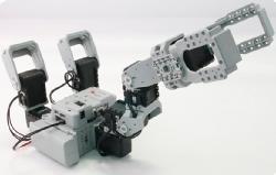 |
Download Assembly Manual Download Task Code Download Video Devices CM-530(1), AX-12+(8)DYNAMIXEL Setting AX-12+ ID[1~8] : Joint ModeRoboPlus Language Function, Call, Load, Calculate, Endless Loop, If, Else, Loop WhileAlgorithm DYNAMIXEL Communication for Position ValueOperation Guide Check whether the responding motor reacts to the control motor’s movement. |
Advanced
| Examples | Description |
|---|---|
1. Dinosaur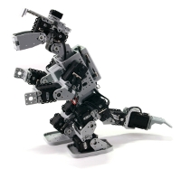 |
Download Assembly Manual Download Task Code Download Motion File Download Video Devices CM-530(1), AX-12+(15), IR Sensor(1)DYNAMIXEL Setting AX-12+ ID[1~15] : Joint ModeRoboPlus Language Function, Call, Load, Lable, Jump, If, Else If, Else, Wait WhileAlgorithm Object detection and motion control using IR Sensor value.Operation Guide— Place an obstacle in the robots path and turn the dinosaur robot on. — The dinosaur robot attacks. — When the obstacle disappears, it continues walking. — When nothing is detected for a while, it will sleep. |
2. Puppy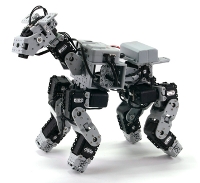 |
Download Assembly Manual Download Task Code Download Motion File Download Video Devices CM-530(1)(Sound Detection, Timer), AX-12+(17), IR Sensor(1)DYNAMIXEL Setting AX-12+ ID[1~17] : Joint ModeRoboPlus Language Function, Call, Load, Lable, Jump, If, Else If, Wait WhileAlgorithm Motion control depending on the sound detection of the IR Sensor and Timer.Operation Guide— Place an obstacle in the robots path and turn the puppy robot on. — When a sound is detected, it will walk avoiding obstacles. — If you touch its mouth, it will do cute things. — It will do different things depending on the number of claps. — When nothing is detected for a while, it will sleep. |
3. King Spider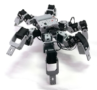 |
Download Assembly Manual Download Task Code Download Motion File Download Video Devices CM-530(1)(Timer), AX-12+(18), IR Sensor(2)DYNAMIXEL Setting AX-12+ ID[1~18] : Joint ModeRoboPlus Language Function, Call, Load, Lable, Jump, If, Wait WhileAlgorithm Application motion control depending on the sound detection of the IR Sensor and Timer.Operation Guide— When it detects an object while walking, it will avoid it. — It will attack when something is detected near the front. — When an object is detected above it, it will crumple up its body. — When nothing is detected for a while, it will sleep. |
4. Scorpion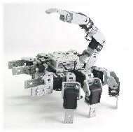 |
Download Assembly Manual Download Task Code Download Motion File Download Video Devices CM-530(1)(Sound detection), AX-12+(18), DMS Sensor(1)DYNAMIXEL Setting AX-12+ ID[1~18] : Joint ModeRoboPlus Language Function, Call, Load, Lable, Jump, If, Else If, Loop For, Wait WhileAlgorithm Application motion control depending on the number of sounds detected and DMS Sensor value.Operation Guide— The robot sleeps when you first turn it on. — The robot will awake when you clap. — If you clap twice when the robot is awake, it will run away. — The closer your hand gets to the sensor, the tail will rise to threaten you. — If you get too close, it will attack. |
5. Lizard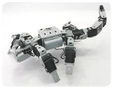 |
Download Assembly Manual Download Task Code Download Motion File Download Video Devices CM-530(1), AX-12+(14), IR Sensor(1),DMS Sensor(1)DYNAMIXEL Setting AX-12+ ID[1~14] : Joint ModeRoboPlus Language Function, Call, Load, Calculate, Endless Loop, If, Else If, Else, Wait WhileAlgorithm Obstacle avoidance motion control using the IR Sensor and DMS Sensor value.Operation Guide— It will being crawling once turned on, and will stop when it detects an object then avoid it. — When the tail is caught, it will try to escape. |
References
Replacing Fuse
The fuse in the CM-510/CM-530 prevents it from overloading,which can damage the circuit.
If the CM-510/CM-530 does not turn on with the battery but turns on when connected to the SMPS, replace your fuse.
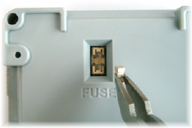
※ The size of the fuse is shown below. Use a 125V/5A~10A fuse.
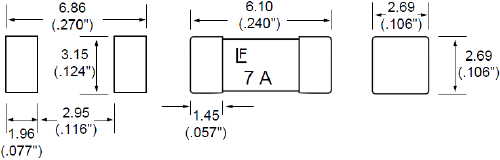
※ How to replace the fuse
-
Find the fuse on the back of the CM-510/CM-530.
-
Use a pincette to replace the fuse with a new one.
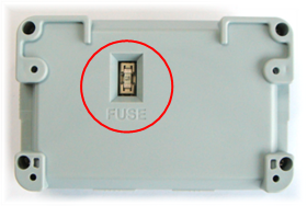
DYNAMIXEL Management
DYNAMIXEL used as robot actuators possess many functions. This section explains how to change the dynamixel’s settings.
Changing the ID
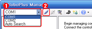
- Select the port the controller is connected to.
-
Click “Connect”.
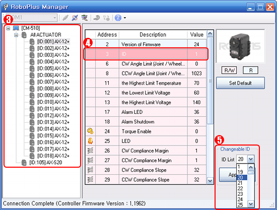
- A list of connected dynamixels is shown on the left. Click on the dynamixel you wish to change the ID of.
- Click on the ID row in the Control Table.
-
Click on the ID List combo box to see a list of possible ID’s. Select the ID, then click Apply.
- To use in RoboPlus Motion and RoboPlus Task, the ID must be within the following ranges.
- The DYNAMIXEL’s ID must be between 0 and 25.
- The ID for AX-S1 should be set between 100 and 109.
Changing the Movement Mode
The dynamixel can operate in 2 different modes.
- Wheel Mode : Rotates 360 degrees like a regular motor.
- Joint Mode : Moves at a set angle with normal servo motors.
The mode can be changed using RoboPlus Manager. Once the mode is set, it will be maintained, even when turned off.
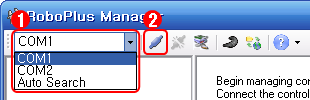
- Select the port the controller is connected to.
-
Click “Connect”.
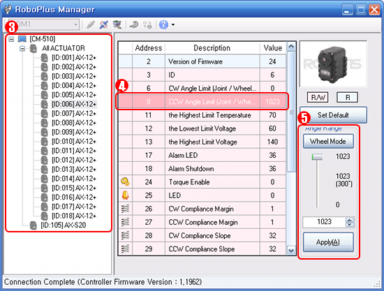
- A list of connected DYNAMIXEL is shown on the left. Click on the DYNAMIXEL you wish to change the mode of. Then, click on the CW/CCW Angle Limit line in the Control Table.
-
To set to Wheel Mode, change the CW/CCW Angle Limit value to “0.” Or, simply click on the “Wheel Mode” button.
- To set to Joint Mode again, set the CW/CCW Angle Limit value to any number other than “0”. The initial values for Joint Mode are “0” for CW Angle Limit, and “1023” for CCW Angle Limit.
Troubleshooting
If you cannot find the dynamixel you are looking for using RoboPlus Manager, try the following :
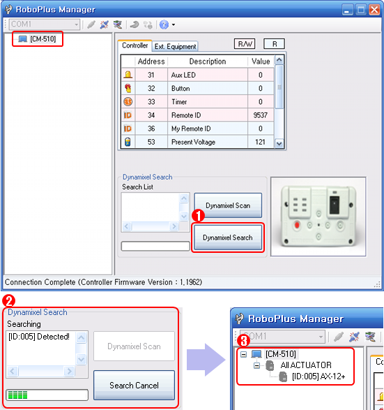
- Connect just 1 DYNAMIXEL and check if there are any duplicate IDs. If you see a DYNAMIXEL on the left even though only 1 DYNAMIXEL is connected, there is a high probability of a duplicate ID. Change the ID immediately.
- If you are unable to find any DYNAMIXEL as in the image below, click on “DYNAMIXEL Search”. If the communication speed is not set to 1Mbps, the “DYNAMIXEL Search” function automatically resets the controller’s communication speed to 1Mbps to enable it to be recognized.
If the problem persists, your dynamixel may need repair. Please contact the service department of the company you purchased from.
ZIGBee Wireless Control
ZIGBee
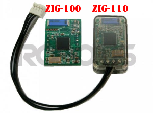
ZIG-100/110 uses ZIGBee for wireless communication. ZIGBee, like Bluetooth, is the communication technology commonly used in Personal Area Network (PAN). The communication quality of ZIGBee is better than that of IR, so it allows many users to control their robots without interferences.
CAUTION : Please note that not all products include a zigbee module and may need to be purchased separately.
Controller & ZIGBee
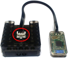
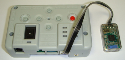
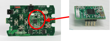
OLLO and Bioloid both use the RC-100, which uses IR communication method. To upgrade to the Zigbee communication method, you must purchase the ZIG-110 set separately. The ZIG-110 set includes one Zig-100 module, which is attached to the RC-100, and one Zig-110 module which is attached to the Controller.
NOTE : The modules in a single Zigbee set have been preconfigured to communicate with each other. Therefore, a module from one set may not work with a module from another set. Please be careful not to mix them up.
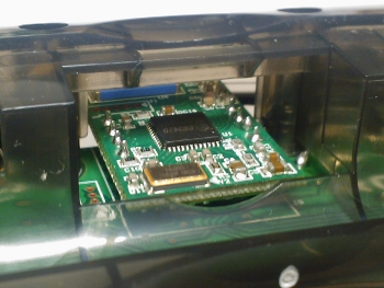
| ZIG-100 installed in RC-100 | ZIG-110 installed in CM-100 |
|---|---|
 |
 |
| ZIG-110 installed in CM-510 | ZIG-100 installed in CM-5 |
|---|---|
 |
 |
Control Multiple Robots
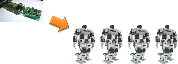
This method is to give out commands at once to several robots being used for dance or demonstration
Gives out commands to the robot at once using the zigbee module’s broadcast mode
Bioloid(Entry/Advanced)
-
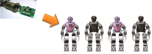
Communication with the Zig2Serial and various robots
-
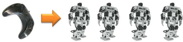
Communication with the RC-100 and various robots
- To use the CM-5, connect the controller and ZIG-100 module together.
- Use the RoboPlus Manager to set the wireless ID of ZIG-100 module on the opposite party’s robot to 65535.
- No need to set the broadcast channel for communication.
- Use the RC-100 to give commands directly or use the Zig2Serial to give commands using the PC.
| Device | Channel Default Value | Whether or not the channel can be changed |
|---|---|---|
| CM-5 | 1 | Unchangeable |
| Zig2Serial | 1 | Changeable |
| RC-100 | 1 | Changeable |
The channel for the ZIG-100 mounted on the CM-5 is unchangeable. Thus, all users must set their channel to #1 for broadcast communication. All channels for the devises must pair to communicate.
Bioloid Premium Kit
-
Communication with the Zig2Serial and various robots
-
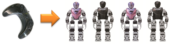
Communication with the RC-100 and various robots
- When using the CM-510, connect the ZIG-100 module with the controller.
- Use the RoboPlus Manager to change the opposite party’s wireless ID to 65535.
- The channel on the ZIG-110 connected to the controller it set to #4, so the channels on the Zig2Serial and RC-100 must be set to #4.
- How to change the RC-100 channel
- How to change the Zig2Serial channel
| Device | Channel Default Value | Whether or not the channel can be changed |
|---|---|---|
| CM-510 CM530 |
4 | Unchangeable |
| Zig2Serial | 1 | Changeable |
| RC-100 | 1 | Changeable |
The channel for the zigbee connected to the controller is not changeable. Thus, all users must set their channel to #4 for broadcast communicationAll channels for the devises must pair to communicate.
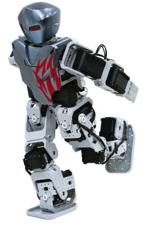
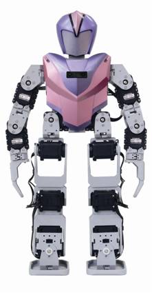
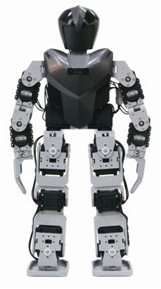
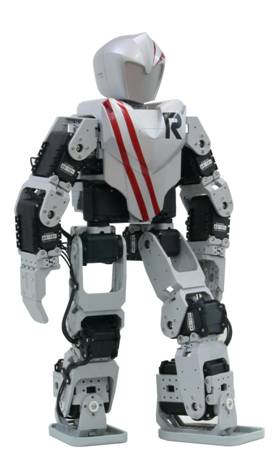
Customizing Robot
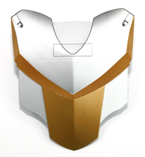
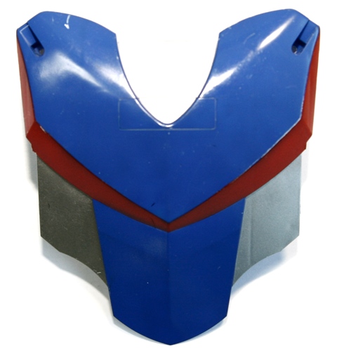
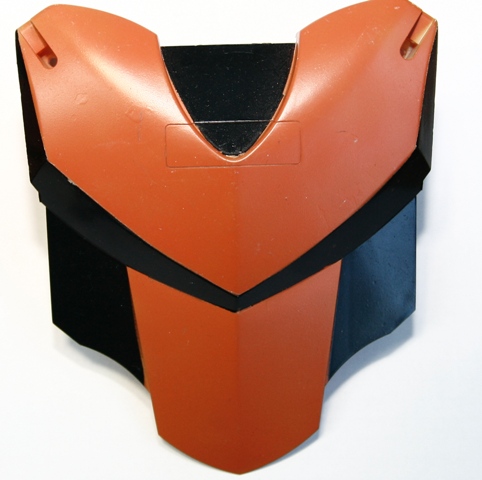
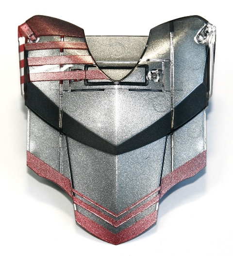
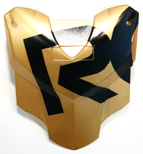
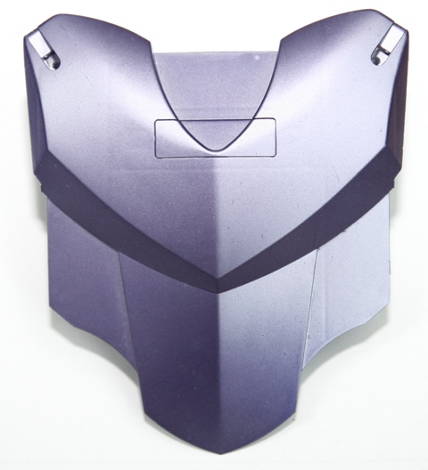
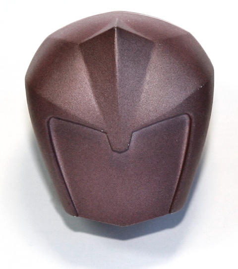
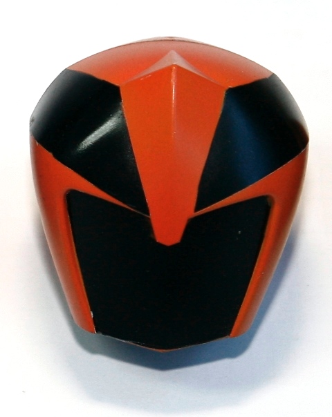
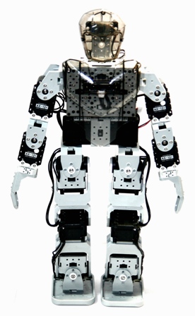
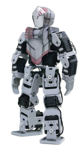
Use the semi-transparent skins provided only in the Premium Kit to make your humanoid unique.
Customizing your semi-transparent skins
Samples of customized chest skins
 |
 |
|---|---|
 |
 |
 |
 |
Samples of customized head skins
Samples of robots with customized skins
 |
 |
 |
|---|---|---|
 |
 |
 |
Adding Sensors
With the Bioloid Premium Kit, you can connect additional IR Sensor and Touch Sensor to the CM-530.
For more information on each sensors, please click on the names of the sensors.
IR Sensor
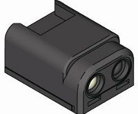
- IR Sensor Applications
- The IR sensor can detects objects in front of the robot.
- It can also be used to detect object on the side when walking or moving.
More information
Touch Sensor
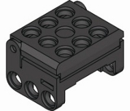
- Touch Sensor Applications
- The touch sensor enables the robot to feel when it has been touched.
- For example, the sensor can be used to make the robot react to certain touches.
More information
Make Your Own Sensor
You can make your own sensor with simple control functions using the ADC port and OUT port on CM-510/CM-530.
CAUTION : Connecting poorly designed circuits may damage the controller. Please be sure to acquire sufficient knowledge about circuits beforehand.
PIN Information
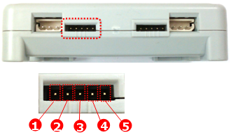
- Below is a pin diagram of CM-510’s external port.
- OUT : 5V Output
- VCC (5V)
- ADC : Can read analog signals made by users.
- GND
- NC : Not used
- Below is a pin diagram of CM-530’s external port.
- OUT1 : 3.3V Output (Maximum Allowed Current 0.3A)
- VCC (5V)
- ADC : Can read analog signals made by users.
- GND
- OUT2 : 3.3V Output (Maximum Allowed Current 0.3A)
NOTE : Please use the 5P Cable when using other sensors. The 5P cable can be purchased from ROBOTIS.
Controlling User’s Device
External Output Control
Below is an example of an LED circuit to turn the LED on and off using the OUT port (Pin 1).
You need to adjust the amound of resistance depending on the type of controller and/or the type of LED.
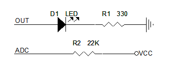
A high signal can be sent to the OUT port using RoboPlus Task.
- Select the user’s device in the writable parameter such as LOAD and CALCULATE, then select the port on which the device is connected.
- Then, set the high signal to the readable parameter using a constant.
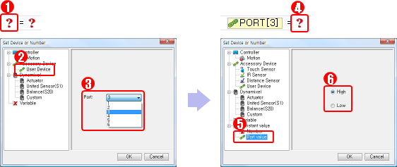

When the code above is executed, high signal will be sent to the OUT port of the device connected to PORT 3, and the LED will turn on.
Reading the ADC Value
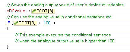
Most of the sensors used in robots, such as IR sensors and distance sensors, support analog output. The CM-510/CM-530 can use its external ports to read the sensor’s analog output signals. These sensors may be designed by the user or bought from a store.
- Below is an image of a tilt sensor. When the sensor is tilted, it prints the tilted value as the analog singal.
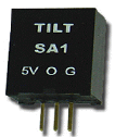
- The left pin of the tilt sensor is 5V VCC. The center is an analog signal output pin, and the right pin is GND. This sensor can be used by connecting its pins to the corresponding pins on CM-530’s/CM-510’s external port. To try for yourself, please refer to the pin information for CM-530’s/CM-510’s external ports.
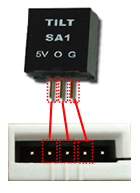
- You can incorporate the sensor’s analog output to your robot’s movements as in the example below.
Gripper Assembly
- Users can add grippers to humanoid robots to fit their needs.
- Grippers are useful when holding or throwing things.
Materials
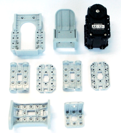
There are 2 spare AX-12+’s when assembling a humanoid Type B or Type C using the Bioloid Premium Kit.
You can use these spare parts to make a gripper to your humanoid.
Below are the parts required to make a gripper.
Making a gripper
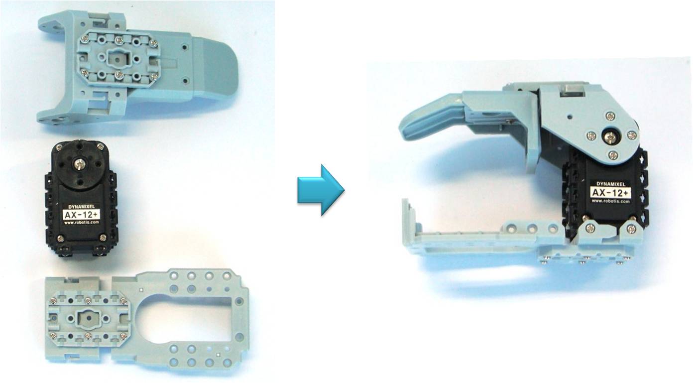
The image above shows how to make a gripper using frames and an AX-12+. Make two of these if you want to attach a gripper on both hands.
Attaching Grippers
By making a robot with grippers, you can expand the things you can do with the robot.
For more information on controlling the gripper robot, please refer to gripper control.
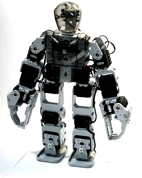
Below is an image of a Type B humanoid with a grippers.
AX-12+ #9 was used for the right gripper and AX-12+ #10 was used for the left.
Описание товара Образовательный робототехнический набор ROBOTIS Premium (Bioloid Premium)
Образовательный робототехнический набор ROBOTIS Premium (Bioloid Premium)
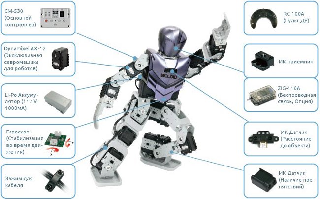
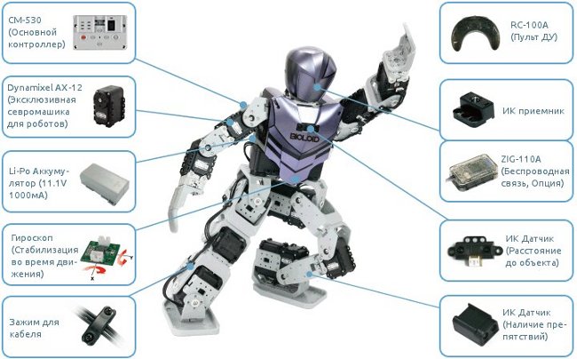
Bioloid Premium — человекоподобный робот, обладающий самостабилизацией положения тела, обеспечивающей идеальную устойчивость при ходьбе. Набор позволяет собрать гуманоида, паука, динозавра и другие модели.
Bioloid Premium оснащен различными датчиками, включая гироскоп, датчик расстояния и инфракрасный модуль. Есть возможность дистанционного управления через ИК-модуль или bluetooth модули. В комплект включено программное обеспечение RoboPlus для обучения робота новым движениям, а так же ПО, дающее возможность низкоуровневого программирования на языке С. Для придания уникального вида корпусу, имеется специальный полупрозрачный пластик. Робот построен на основе сервомоторов Dynamixel, объединенных в единую сеть, обеспечивающую точность управления и простоту подключения новых модулей.
Особенности
- Идеальная устойчивость и сохранение положения тела при ходьбе
- Наличие различных датчиков и портов для расширения
- Удаленное управление с помощью радиоканала на базе протокола Bluetooth
- Программирование на языке семейства C, а также в среде RoboPlus
- Возможность создания разнообразных моделей роботов
Комплектация
- AX-12 (Сервопривод) Dynamixel : 18 шт.
- Двухосный гироскоп: 1 шт.
- ИК дальномер: 1 шт.
- ИК датчик препятствия: 2 шт.
- RC-100(Пульт ДУ): 1 шт.
- Набор обшивки для корпуса робота
- Li-Po аккумулятор (11.1V, 1000mA/PCM) : 1 шт.
- Зарядное устройство
- CD-диск с программным обеспечением
- Самоучитель (3-и комплексных примера человекоподобных роботов)
- Отвертка, Зажим для кабеля
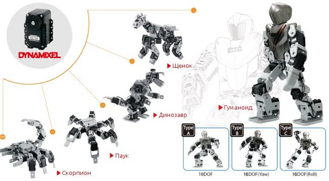
Примеры проектов
BIOLOID Premium Kit включает все необходимое для создания шагающих роботов
Микроконтроллер CM530
CM530 — микроконтроллер с портами для датчиков и сервомоторов DYNAMIXEL
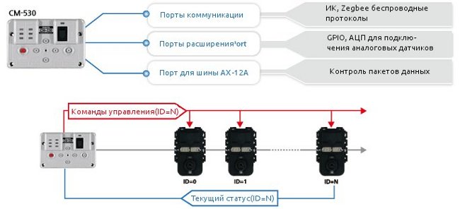
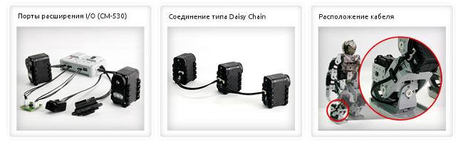
Подключение периферийных устройств к контроллеру CM-530
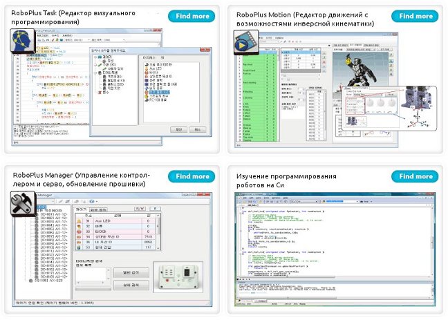
RoboPlus — удобная среда разработки для BIOLOID
Список деталей
47912620
ОБРАЗОВАТЕЛЬНАЯ-РОБОТОТЕХНИКА.РФ (Роботоехнические конструкторы для образования).
Дистрибьюция программного обеспечения и учебного оборудования, для создания непрерывной развивающей образовательной среды..
Выгодные цены на Образовательный робототехнический набор ROBOTIS Premium (Bioloid Premium)
Минимальная сумма заказа 10000 рублей.
Уважаемые покупатели! На нашем сайте ведутся работы по обновлению ассортимента продукции. Наличие и цены интересующего Вас товара уточняйте у менеджера.
Отличный набор. Все заявленное в описании верно. Собрал сразу гуманойда с максимальным числом степеней свободы. Есть богатые возможности программирования как на оригинальном блоке: проверил и графическую среду и загрузку своих прошивок, так и с других устройств: Windows, или Raspberry Pi. Советую сразу брать преобразователь USB2Dynamixel, когда захочется порулить двигателями из своей программы его может не оказаться под рукой. Кроме того, можно докупать дополнительные совместимые с протоколом Dynamixel чуть более дешёвые сервы для клешней (т.к. с макс. числом степеней свободы сервы тратятся на ноги) SR-508H, а они имеют интерфейс не TTL, а RS-485, переходник позволяет сразу их протестировать (хотя можете попытать счастья с USB2TTL преобразователями и RS485 трансивером. Родной аккумулятор по неизвестным причинам сдох лёжа на столе будучи нормально заряженным (изначально он уже был каким то вздувшимся), но я заменил его аккумулятором большей ёмкости, пересадив разъемчик со старого, даже устройство балансирующей зарядки подошло. Рекомендую между забегами переводить заряд аккумулятора в режим хранения (~40% от макс заряда).
-
4
Potential
To say this kit is not for children under ages, but has the potential to do more. Like the engineer kit robotis should have included a vision with the raspberry pi. It’s a good kit to start with I think, but only for mature kids to adults not bad Robotis
-
5
Happy with the product.
Posted by Marco Sarmiento on 25th Jun 2019
This robot was acquired to work with children in a robotics center in Ecuador, an excellent product to motivate and initiate them in the exciting world of robotics.
-
5
Satisfied with the recent order
Posted by Venkat on 20th Oct 2018
This robot can do almost everything I wanted to do. Well build quality and amazing performance by servo motors. It is better to have more example codes to perform different actions inbuilt.
BIOLOID Premium kit – набор для создания различных шагающих роботов на основе моторов Dynamixel и контроллера СМ-530, для образования, игр и соревнований. BIOLOID – это популярная серия программируемых робототехнических конструкторов компании Robotis. Серия представлена разнообразными универсальными наборами, которые подойдут как начинающим робототехникам, так и специалистам, работающим над решением актуальных робототехнических задач.
Показать описание полностьюСкрыть описание
Конструктор состоит из 18 серводвигателей, контроллера, набора датчиков – гироскопического, инфракрасного для определения расстояния, двух инфракрасных для обеспечения безопасности при ходьбе и аккумулятора. Все это соединено в единую сеть посредством системы шлейфов. Также в наборе есть пульт для управления роботом и набор пластиковых элементов для придания уникального вида собранным моделям.
Сборка роботов
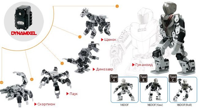
Сама по себе сборка роботов из набора BIOLOID Premium трудоемкий, но увлекательный процесс. В набор конструктора входят специальные соединительные скобы и крепежные элементы, с помощью которых сервомоторы собираются сначала последовательно, потом в узлы, а затем узлы компонуются в единый механизм. Вы можете собрать паука, который очень правдоподобно передвигается на шести лапах и встает в оборонительную позу, динозавра, собаку и человекоподобного робота, который обладает системой самостабилизации, что дает отличную устойчивость при ходьбе и других движениях робота.
Управление и программирование
После сборки всех узлов робота и подсоединения аккумулятора можно произвести пробный запуск механизма. По умолчанию робот имеет четыре основных режима:
— тестовый, для проверки правильности сборки
— демонстрационный, когда робот, стоя на месте, машет руками, делает поклоны и другие движения;
— режим автономного передвижения, в котором робот передвигается и обходи препятствия, обнаружив их при помощи инфракрасного датчика;
— режим дистанционного управления, в котором роботом можно управлять посредством пульта, всего запрограммировано 16 действий кроме ходьбы, это разные акробатические движения, например, стойка на голове, приветствия, поклоны, а также движения для боев с соперниками и игры в футбол.
В комплект набора BIOLOID Premium входит программное обеспечение, с помощью которого можно управлять движениями и программировать любые линии поведения робота.
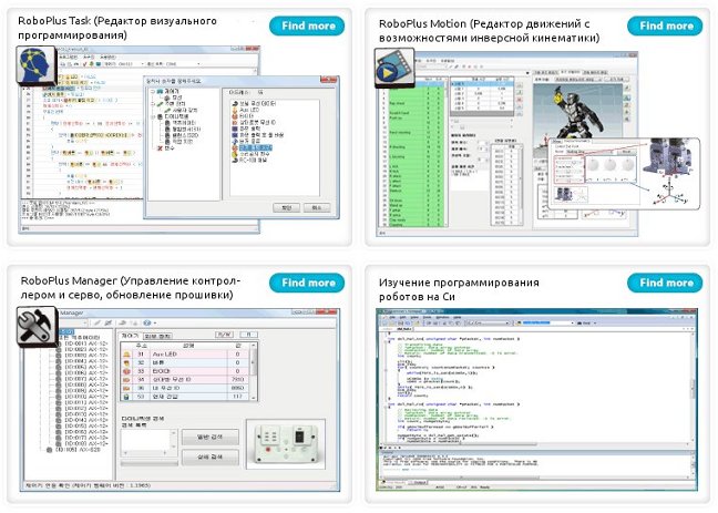
Для программирования используется среда RoboPlus, где разнообразные движения роботу задаются с помощью редактора RoboPlus Motion и программируются в визуальном редакторе RoboPlus Task.
Также доступно программирование на языке семейства «С».
Обновлено: 27.11.2023
Bioloid Premium Kit от корейской компании Robotis – это набор создания продвинутого двуного робота, способного на различные действия. Этот образовательный конструктор направлен на возрастную категорию от 15 лет, позволяющий юным и взрослым техникам собрать не только яркого внешне робота, но и достаточно умного.
В данном обзоре мы рассмотрим особенности, достоинства и недостатки этого набора, а также его основные возможности.
Сборка
Bioloid Premium Kit – довольно сложный технически комплект, из которого можно собрать до 26 различных роботов.
Итак, для начала рассмотрим состав набора:
- полный комплект корпусных деталей, крепежей, предохранителей;
- комплект датчиков (ИК-дальномер, ИК-бампер, гироскоп);
- контроллер СМ-510;
- Li-Po аккумулятор;
- зарядные и интерфейсные кабели;
- 18 серводвигателей Dynamixel AX-12;
- джойстик ДУ.
Естественно, к комплекту прилагается подробная инструкция о том, как правильно собирать модели.
Сама сборка Bioloid – утомительный, но достаточно увлекательный процесс. Главная особенность здесь в соединении сервоприводов Dynamixel и специальных скоб. Корпус серво разработан таким образом, что с трех его сторон (по бокам и снизу) находятся специальные пазы для гаек. Устанавливаемые в эти пазы, гайки фиксируются надежно и дают возможность установки на корпусе крепежных скоб. Чтобы получить основные узлы робота, нужно последовательно соединить моторчики и крепежные скобы.
Функционал
Основные возможности конструктора рассмотрим на примере самого продвинутого робота, которого можно здесь собрать – гуманоида. Данный аппарат отличается своими функциональными возможностями. Поражает, но он способен выполнять до 16 запрограммированных действий. В демонстрационном режиме робот делает поклоны, машет руками, поворачивает голову, в автономном механизм может свободно ходить, удерживать равновесие и даже танцевать, благодаря двухосному гироскопу. Под дистанционным управлением он уже выполняет запрограммированные действия.
Это могут быть акробатические трюки, как стойка на руках или отжимание. Или игровые действия, например, футбол.
Программирование
Робот управляется с пульта управления RC-100A и работает на контроллере СМ-510. Чтобы добавить ему немного интеллекта, нужно просто его запрограммировать либо на выполнение команд оператора, либо на автономию. Диск с программным обеспечением также идет в коробке с конструктором. Программа называется RoboPlus и содержит заготовки для уже собранных по инструкции моделей. Интерфейс программы визуально понятен. Редактор движения также интересен за счет возможности инверсной кинематики. Конечно, здесь есть возможность программировать робота на C и С++.
Преимущества
- высокое качество деталей
- продвинутые элементы электроники
- широкий функционал
- простое программирование.
Недостатки
- нет возможностей расширения и совмещения с деталями из других наборов
- сервоприводы довольно медленные
- высокая стоимость – около $1200.
Можем сделать вывод: Bioloid Premium – это очень качественный робототехнический комплект, который является не только игровым инструментарием, а расширенным пособием по проектированию, электронике и программированию.
BIOLOID Premium kit – набор для создания различных шагающих роботов на основе моторов Dynamixel и контроллера СМ-530, для образования, игр и соревнований. BIOLOID – это популярная серия программируемых робототехнических конструкторов компании Robotis. Серия представлена разнообразными универсальными наборами, которые подойдут как начинающим робототехникам, так и специалистам, работающим над решением актуальных робототехнических задач.
Конструктор состоит из 18 серводвигателей, контроллера, набора датчиков – гироскопического, инфракрасного для определения расстояния, двух инфракрасных для обеспечения безопасности при ходьбе и аккумулятора. Все это соединено в единую сеть посредством системы шлейфов. Также в наборе есть пульт для управления роботом и набор пластиковых элементов для придания уникального вида собранным моделям.
Сборка роботов
Сама по себе сборка роботов из набора BIOLOID Premium трудоемкий, но увлекательный процесс. В набор конструктора входят специальные соединительные скобы и крепежные элементы, с помощью которых сервомоторы собираются сначала последовательно, потом в узлы, а затем узлы компонуются в единый механизм. Вы можете собрать паука, который очень правдоподобно передвигается на шести лапах и встает в оборонительную позу, динозавра, собаку и человекоподобного робота, который обладает системой самостабилизации, что дает отличную устойчивость при ходьбе и других движениях робота.
Управление и программирование
После сборки всех узлов робота и подсоединения аккумулятора можно произвести пробный запуск механизма. По умолчанию робот имеет четыре основных режима:
— тестовый, для проверки правильности сборки
— демонстрационный, когда робот, стоя на месте, машет руками, делает поклоны и другие движения;
— режим автономного передвижения, в котором робот передвигается и обходи препятствия, обнаружив их при помощи инфракрасного датчика;
— режим дистанционного управления, в котором роботом можно управлять посредством пульта, всего запрограммировано 16 действий кроме ходьбы, это разные акробатические движения, например, стойка на голове, приветствия, поклоны, а также движения для боев с соперниками и игры в футбол.
В комплект набора BIOLOID Premium входит программное обеспечение, с помощью которого можно управлять движениями и программировать любые линии поведения робота.
Для программирования используется среда RoboPlus, где разнообразные движения роботу задаются с помощью редактора RoboPlus Motion и программируются в визуальном редакторе RoboPlus Task.
Образовательный робототехнический комплект представляет собой двухуровневую образовательную систему для изучения базовых основ проектирования робототехнических систем и развития углубленных профориентационных знаний в области многокомпонентных робототехнических систем.
Данное предложение не является публичной офертой и носит рекомендательный характер с целью подбора оптимальной комплектации оборудования. Комплектация оборудования может изменяться в соответствие с запросом Заказчика. Стоимость и состав предложения могут изменяться в соответствие с предложением Поставщика. Срок и условия поставки определяются индивидуально в зависимости от комплектации и количества запрашиваемого оборудования.
Образовательный робототехнический комплект «СТЕМ Академия. Расширенная версия» представляет собой набор, позволяющий организовать двухуровневый образовательный процесс: на первом уровне обучения предлагается изучение базовых основ проектирования и управления роботами и робототехническими комплексами (в т.ч. манипуляционными роботами и роботами со сложной кинематикой), а на втором уровне обучения — развитие углубленных профориентационных знаний в области многокомпонентных робототехнических систем.
Комплект позволяет сконструировать не менее 25 различных моделей роботов, начиная от простейших моделей и до моделей со сложной кинематикой с использованием большого числа сервоприводов. Благодаря этому становится возможным разрабатывать модели роботов со сложной кинематикой, в том числе различные шагающие шасси и человекоподобных роботов.
Образовательный комплект также может применяться в большинстве различных робототехнических соревнований — в рамках ВРО, РобоФест (PROFEST), Робофинист и т.д., а так же в специализированных соревнованиях по боям, танцам, футболу и гонкам человекоподобных роботов. Функционал робототехнического комплекта «СТЕМ Академия. Расширенная версия» позволяет студентам младших курсов и бакалаврам технических ВУЗов использовать его для глубокого изучения робототехники и исследовательской деятельности.
Состав комплекта «СТЕМ Академия. Расширенная версия»:
— Сервомодуль (мощный) — 22 шт;
— Мотор со встроенным абсолютным энкодером — 4 шт;
— Комплект конструктивных элементов (скобы, пластины,фланцы,шестерни);
— Комплект колес;
— Комплект корпусных элементов;
— Инфракрасный дальномер — 1 шт;
— ИК-датчик — 2 шт;
— Гироскоп 2х-осевой — 1шт;
— Программируемый контроллер — 1шт;
— Модуль технического зрения — 1 шт;
— Модуль стереозрения — 1 шт;
— Аккумуляторная батарея типа LIPO 11,1V 1000mAh — 1 шт;
— Зарядное устройство — 1 шт;
— Сетевой адаптер — 1 шт;
— Инфракрасный приемник — 1шт;
— Инфракрасный джойстик — 1шт;
— Модуль беспроводной связи WiFi;
— Учебное пособие для преподавателя;
— Программируемый контроллер ( совместим с микрокомпьютером на базе ОС Linux ) — 1 шт;
— Аккумуляторная батарея типа LIPO 11,1V 1000mAh — 1 шт.
Образовательный набор для изучения многокомпонентных робототехнических систем и манипуляционных роботов «Образовательный робототехнический комплект «СТЕМ Мастерская». Расширенный» предназначен для изучения робототехнических технологий, основ информационных технологий и технологий промышленной автоматизации, а также технологий прототипирования и аддитивного производства.
Данное предложение не является публичной офертой и носит рекомендательный характер с целью подбора оптимальной комплектации оборудования. Комплектация оборудования может изменяться в соответствие с запросом Заказчика. Стоимость и состав предложения могут изменяться в соответствие с предложением Поставщика. Срок и условия поставки определяются индивидуально в зависимости от комплектации и количества запрашиваемого оборудования.

Образовательный набор для изучения многокомпонентных робототехнических систем и манипуляционных роботов «Образовательный робототехнический комплект «СТЕМ Мастерская». Расширенный» предназначен для изучения основ разработки и конструирования моделей промышленных манипуляционных роботов различного типа и автономных мобильных роботов. В состав комплекта входят сервомодули, представляющие собой модели промышленных автоматизированных приводов со встроенной системой управления. Применение данного типа сервомодулей позволяет разрабатывать модели манипуляционных роботов с различными типами кинематической схемы, обладающих высокой точностью и динамикой движения.
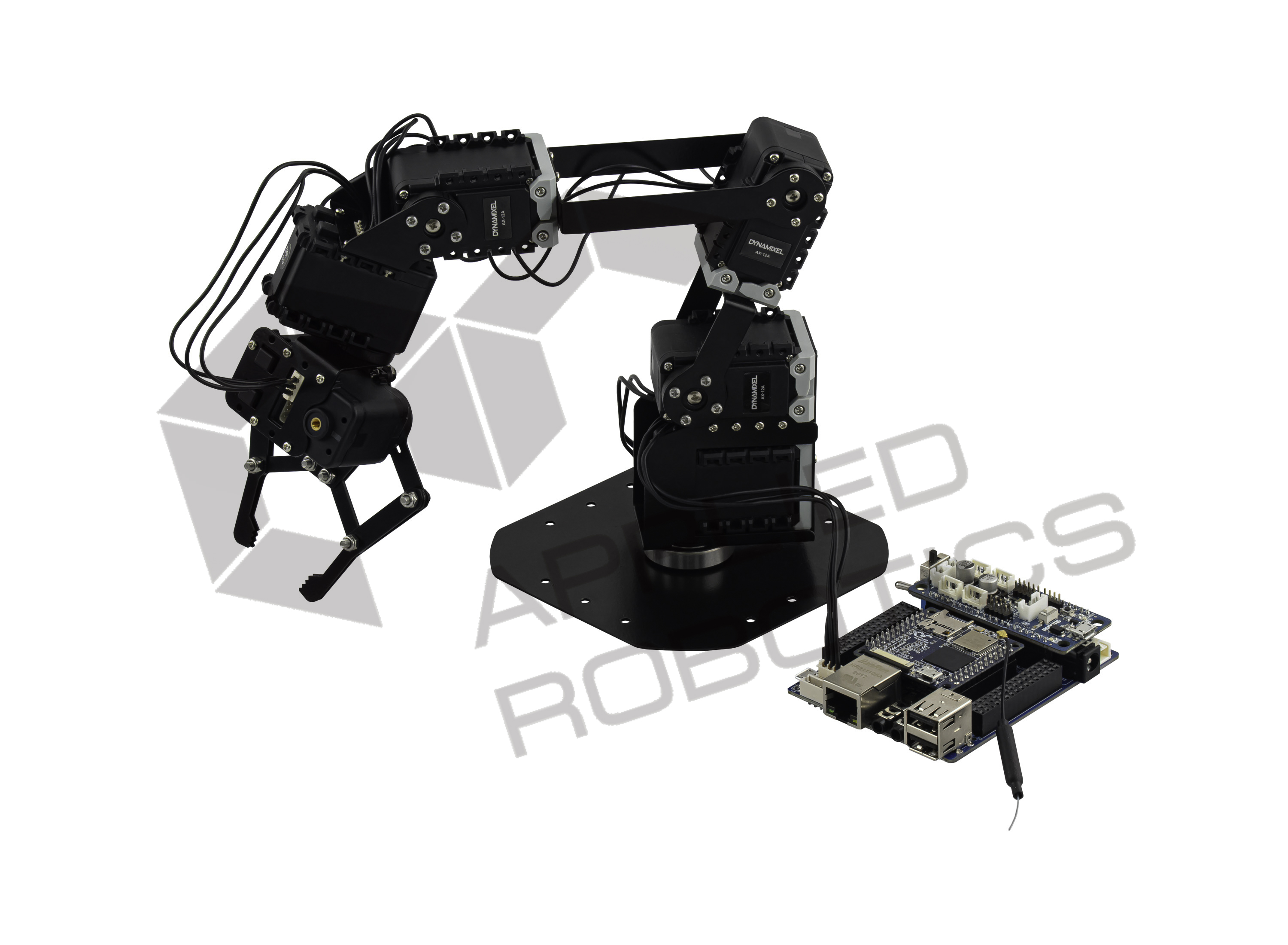
Образовательный набор для изучения многокомпонентных робототехнических систем и манипуляционных роботов «Образовательный робототехнический комплект «СТЕМ Мастерская». Расширенный» позволит учащимся на примере собираемых из набора манипуляционных роботов ознакомиться с основными технологическими принципами, применяемыми на современном производстве, и научиться выполнять различные технологические операции с использованием ручных инструментов и специализированного оборудования. Путем использования данного комплекта в проектной деятельности и работе в команде, учащиеся изучат виды технологических операций на производстве, основы проектирования гибких производственных ячеек и разработки систем управления манипуляционными роботами. Также они узнают об инженерных профессиях и специальностях, необходимых на современном производстве и в Индустрии 4.0.

Комплектация
- Конструктивные элементы из металла для сборки модели манипуляционного робота с угловой кинематикой, 23 шт
- Конструктивные элементы из металла для сборки модели манипуляционного робота с плоско-параллельной кинематикой, 30 шт
- Конструктивные элементы из металла для сборки модели манипуляционного робота с DELTA кинематикой, 10 шт
- Крепежные элементы (винты различного номинала и длины), 64 шт
- Крепежные элементы (гайки различного номинала), 64 шт
- Элементы для создания шарнирных соединений, 7 шт
- Соединительные кабели различной длины, 7 шт
- Интеллектуальный сервомодуль с интегрированной системой управления, 7 шт
Сервомодуль представляет собой единый электромеханический модуль, включающий в себя привод на базе двигателя постоянного тока, понижающий редуктор, встроенную систему управления. Сервомодуль обладает интегрированной системой управления, обеспечивающей обратную связь, контроль параметров — положение вала, скорость вращения, нагрузка привода, а также обеспечивающей возможность последовательного подключения друг с другом и управления сервомодулями по последовательному полудуплексному асинхронному интерфейсу. Имеется режим постоянного вращения выходного вала.
Технические характеристики привода:
Нижняя граница диапазона допустимого напряжения питания — 9 В. Верхняя граница диапазона допустимого напряжения питания — 12 В. Передаточное отношение редуктора — 254. Максимальный момент — 1,5 Н*м. Нижняя граница диапазона номинальной скорости вращения в режиме постоянного вращения — 0 об/мин. Верхняя граница диапазона номинальной скорости вращения в режиме постоянного вращения — 59 об/мин. Максимальная величина угла поворота в режиме позиционного управления — 300 угловых градусов. Разрешающая способность — 0,29 угловых градусов. Размеры сервомодуля (ДхШхВ) — 32х50х40 мм. - Робототехнический контроллер, 1 шт
Робототехнический контроллер представляет собой модульное устройство, включающее в себя одноплатный микрокомпьютер для выполнения сложных вычислительных операций, периферийный контроллер для управления внешними устройствами и плату расширения для подключения внешних устройств. Модули робототехнического контроллера обладают одновременной конструктивной, аппаратной и программной совместимостью друг с другом. Имеется конструктивная, интерфейсная и электрическая совместимость робототехнического контроллера с опционально встраиваемым внешним микрокомпьютером.
Робототехнический контроллер обеспечивает возможность программирования с помощью средств языков С/С++, Python и свободно распространяемой среды Arduino IDE, а также управления моделями робототехнических систем с помощью среды ROS. Количество портов для подключения опционально встраиваемого внешнего микрокомпьютера — 48 шт. Имеется встроенный опциональный микрокомпьютер.
Технические характеристики робототехнического контроллера:
Нижняя граница диапазона питания внешней аккумуляторной батареи — 6,8 В. Верхняя граница диапазона питания внешней аккумуляторной батареи — 12 В. Порты для подключения внешних цифровых устройств — 16 шт. Порты для подключения внешних аналоговых устройств — 10 шт. Интерфейс 1-wire TTL для подключения по последовательному интерфейсу — 1 шт. Кол-во портов тип 4pin для подключения сервомодулей по последовательному интерфейсу — 2 шт. Программируемые кнопки — 1 шт. Интерфейс PWM — 1 шт. Интерфейс UART — 4 шт. Интерфейс I2C — 2 шт. Интерфейс SPI — 2 шт. Интерфейс для подключения микрофона — 1 шт. Интерфейс для подключения динамиков — 1 шт.
Технические характеристики встроенного опционального микрокомпьютера:
Количество вычислительных процессорных ядер — 4 шт. Оперативная память — 512 МБайт. Имеется встроенные интерфейсы WiFi и Bluetooth. Количество слотов для подключения карты памяти microSD — 1 шт. Встроенный микрофон — 1 шт.
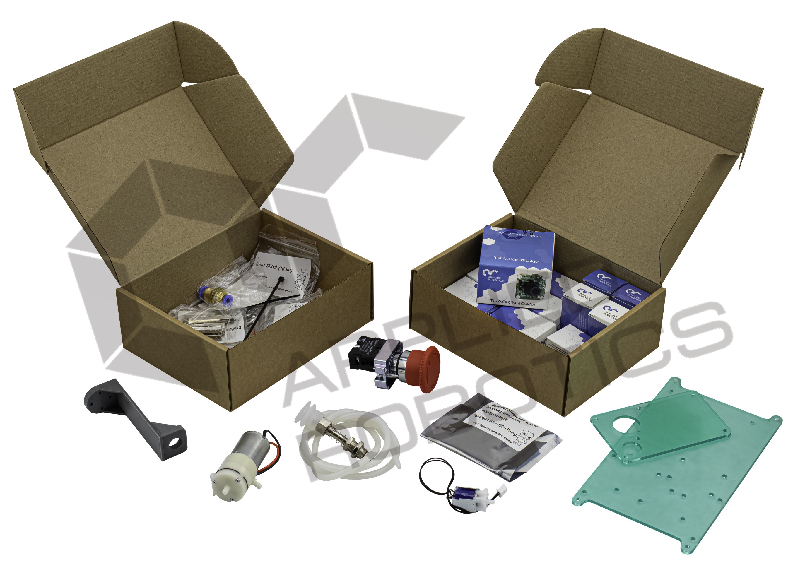
В состав набора входит учебный комплект, включающий в себя учебное пособие, набор библиотек трехмерных элементов для прототипирования моделей манипуляционных роботов, а также программное обеспечение для работы с набором. Учебное пособие содержит материалы по разработке трехмерных моделей мобильных роботов, манипуляционных роботов с различными типами кинематики (угловая кинематика, плоско-параллельная кинематика, дельта-кинематика, SCARA (рычажная кинематика), платформа Стюарта), инструкции по проектированию роботов, инструкции и методики осуществления инженерных расчетов при проектировании (расчеты нагрузки и моментов, расчет мощности приводов, расчет параметров кинематики), инструкции по разработке систем управления и программного обеспечения для управления роботами, инструкции и методики по разработке систем управления с элементами искусственного интеллекта и машинного обучения.
На начальном этапе учащиеся могут разрабатывать модели роботов и программировать их с использованием блочно-графической среды программирования.
На среднем этапе учащиеся могут программировать модели роботов с использованием среды программирования Arduino IDE, используя отечественный робототехнический контроллер.
В рамках начального и среднего этапа учащиеся могут применять аддитивные технологии в процессе разработки и изготовления конструкции робота. Начиная с начального этапа, учащиеся могут также разрабатывать модели автономных роботов с использованием различных сенсорных устройств, в том числе систем технического зрения на базе отечественного модуля.
В рамках старшего этапа учащиеся могут расширить функционал программируемого контроллера за счет установки модуля расширения на базе микрокомпьютера с ОС Linux. Благодаря этому появляется возможность изучать основы разработки робототехнических систем с системами управления на базе ОС реального времени или типа Linux, а также изучать методы сбора и анализа визуальной информации, принципы дистанционного управления и интеграции робототехнических комплексов в системы типа Индустрия 4.0 и Интернет Вещей.
Сложно определиться с выбором?
Укажите ваш номер телефона, мы свяжемся с вами и поможем найти решение!
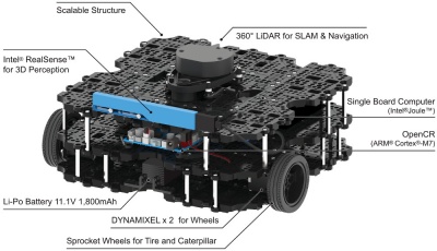

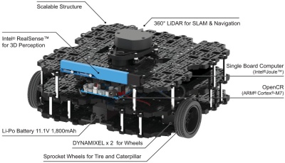
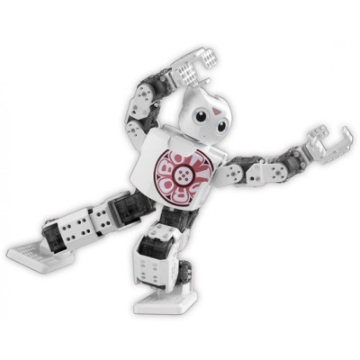
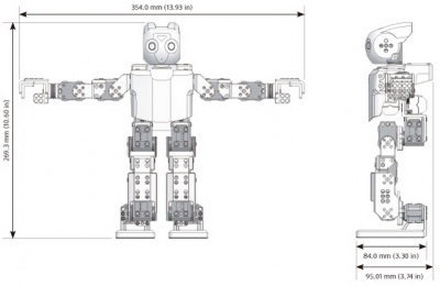
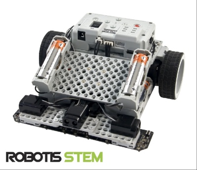
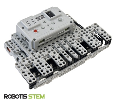
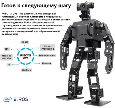
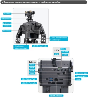




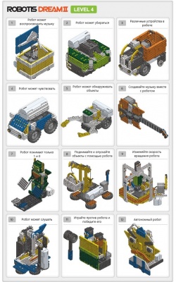

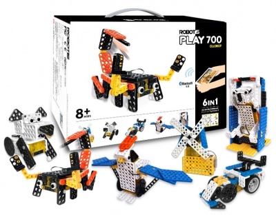
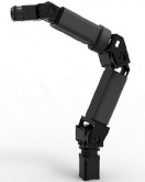
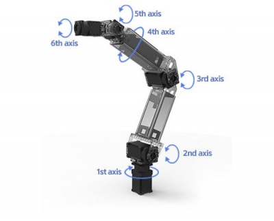
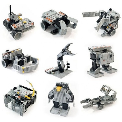
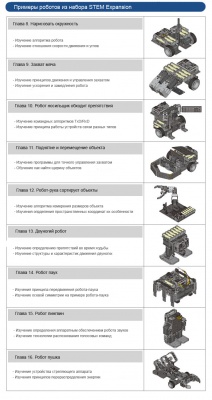


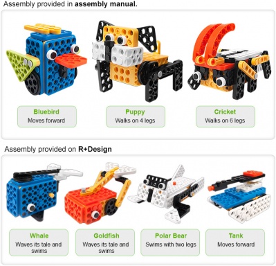
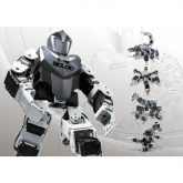
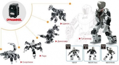
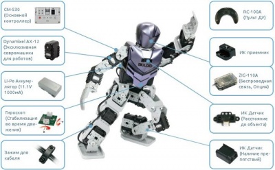
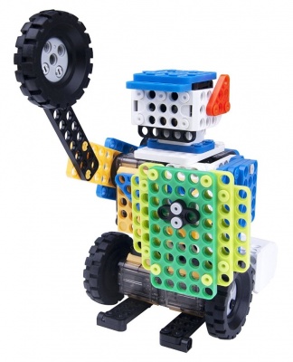
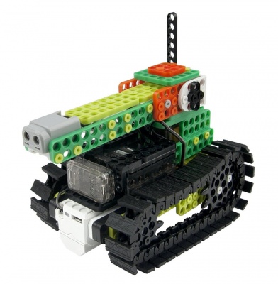


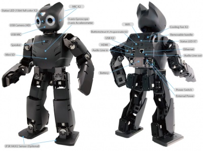
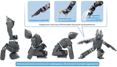
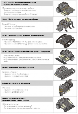
Robotis – это семейство образовательных робототехнических конструкторов, производимых одноименной южнокорейской фирмой. Для увлекающегося техникой ребенка наборы Robotis станут великолепной возможностью получить навыки непосредственного обращения с довольно сложными техническими устройствами. Создать своими руками пусть небольшого, но настоящего и работающего робота – такая задача заинтересует не только подавляющее большинство мальчишек, но и многих девчонок.
Серия Robotis Play, состоящая из двух наборов (Dino и Pet), предназначается для самых маленьких робототехников. Из конструктора Pet можно собрать модели домашних животных, а из Dino – динозавров. Благодаря электромотору собранные фигурки смогут передвигаться на своих собственных ногах. Данная серия отлично подойдет ребятам 6-8 лет.
Линейка Robotis Dream представляет собой настоящую образовательную программу с несколькими уровнями сложности. От простого конструирования по заданной схеме серия плавно подводит ребят к базовым навыкам программирования, изучению использования датчиков и сложных устройств управления роботами. Эти наборы отлично подходят как для комплектования учебных робототехнических кабинетов школьников младшего и среднего возраста, так и для домашних занятий робототехникой.
Robotis Bioloid – самая продвинутая серия от Robotis, позволяющая создавать программируемые робототехнические устройства высокой сложности, имитирующие живые существа. Роботы из наборов этой линейки обладают огромным числом степеней свободы и способны работать абсолютно автономно, с помощью датчиков реагируя на изменение окружающей обстановки. Из таких конструкторов можно создать человекоподобного робота-танцора, прыгающего паука, лающую при приближении человека собаку. Линейка Robotis Bioloid прекрасно подойдет как старшим школьникам, так и взрослым.
Читайте также:
- Детский столик с конструктором
- Игровое поле лего зеленое
- Лего френдс пиццерия детский мир
- Инструкция по сборке лего брик хедс
- Коды на лего бэтмен 2 dc super heroes