

Руководство по эксплуатации и техническому обслуживанию автомобилей Renault Premium DXi 11 330/370/380/410/440/450.
- Автор: —
- Издательство: Диез
- Год издания: —
- Страниц: 256
- Формат: —
- Размер: —

Руководство по эксплуатации и техническому обслуживанию автомобилей Renault Premium.
- Автор: —
- Издательство: Motorist
- Год издания: —
- Страниц: 285
- Формат: —
- Размер: —

Руководство по ремонту автомобиля Renault Premium dCi.
- Автор: —
- Издательство: Терция
- Год издания: —
- Страниц: 184
- Формат: —
- Размер: —

Сборник руководств на английском языке по ремонту автомобиля Renault Premium.
- Автор: —
- Издательство: —
- Год издания: —
- Страниц: —
- Формат: PDF
- Размер: 13,2 Mb
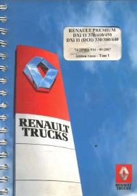
Руководство по эксплуатации и техническому обслуживанию автомобиля Renault Premium.
- Автор: —
- Издательство: Renault
- Год издания: 2007
- Страниц: 156
- Формат: PDF
- Размер: 54,9 Mb

Руководство по эксплуатации, техническому обслуживанию и ремонту автомобилей Renault Kerax 1996-2013 и Renault Premium 1996-2006 годов выпуска.
- Автор: —
- Издательство: Арус
- Год издания: —
- Страниц: 792
- Формат: —
- Размер: —

Руководство по эксплуатации и техническому обслуживанию автомобиля Renault Premium dCi.
- Автор: —
- Издательство: Терция
- Год издания: —
- Страниц: 180
- Формат: —
- Размер: —

Руководство по эксплуатации и ремонту автомобиля Renault Premium.
- Автор: —
- Издательство: Терция
- Год издания: —
- Страниц: 270
- Формат: —
- Размер: —
Руководство по ремонту электрооборудования автомобиля Renault Premium.
- Автор: —
- Издательство: Renault
- Год издания: 1997
- Страниц: 265
- Формат: DjVu
- Размер: 106,3 Mb

Renault Premium owner’s, operators, service and maintenance manuals, error codes list, DTC, spare parts manuals & catalogues, wiring diagrams, schematics free download PDF
See also:
| Title | File Size | Download Links |
| Renault Premium 320 / 370 / 420 dCi Service Manual rus [PDF] | 21.1Mb | Download |
| Renault Premium 330 DXi 11 Service Manual [PDF] | 17.1Mb | Download |
| Renault Premium 380 DXi 11 Service Manual [PDF] | 17.1Mb | Download |
| Renault Premium 440 DXi 11 Service Manual [PDF] | 17.1Mb | Download |
| Renault Premium Bodywork manual [PDF] | 4.2Mb | Download |
| Renault Premium Braking system devices [PDF] | 4.3Mb | Download |
| Renault Premium DXi 11 Service Manual [PDF] | 17.1Mb | Download |
| Renault Premium DXI450 fuse box diagrams [PDF] | 71.2kb | Download |
| Renault Premium DXI450 Wirings Diagrams [PDF] | 6.2Mb | Download |
| Renault Premium EDC BOSH Wiring Diagrams [PDF] | 144.4kb | Download |
| Renault Premium Route 460 4×2 Specifications [PDF] | 367.8kb | Download |
| Renault Trucks – Premium DXi Engine Control Error Codes MID128 [PDF] | 36.6kb | Download |
Comfortable Renault Premium trucks guarantee the driver a pleasant driving experience on any route and flawless work in the transportation of various goods (by the way, the body can be installed under the needs of the enterprise). Reliable and practical design, ergonomic dashboards, and a high level of safety have provided these French trucks with well-deserved popularity. With this technique, you can rely on a difficult situation and be sure that the cargo will be transported on time, even under adverse external conditions. Since the number of owners and drivers of Renault trucks is increasing every year, there was a need for a professional source of information where everything related to the repair, electrical features, use, and maintenance of these machines would be collected and visually presented. Moreover, such a competent Renault Premium repair manual is available on this page, and the manuals will interest readers, regardless of the level of initial knowledge and skills in the field of auto mechanics, from drivers to car service specialists.
Clear illustrations distinguish this Renault Premium workshop manual PDF – there is not a single spread without drawings and diagrams. There are also tables and drawings. In a word, everything that is needed in addition to the main text so that the reader can easily understand any, even not the easiest, topics for him. However, at the same time, the content is well thought out, and you can quickly find exactly what you need on the pages of the manual.
Renault Premium service manuals were informative and convenient, and maximum attention was paid to these trucks’ repair and electrical equipment. At the beginning of the manual, the technical characteristics of the truck, the features of its design, and all its constituent elements are given. For example, everything about the engine, clutch, gearbox, shafts, axles, wheels and other important units, assemblies and systems. At the same time, the instruction manual for Renault Premium is not given in a separate form, but this is not necessary, given the high information content of the guide. The reader who has mastered this manual is unlikely to have questions on this topic because as you study the manual, it becomes clear how to use the equipment in various conditions with maximum working efficiency. The manuals also consider the rules for maintaining a Renault Premium truck by the regulations and prescribed test procedures – settings, inspections, and so on.
In general, headlights, lighting, and electrical equipment are separate topics in the proposed manuals. All Renault Premium wiring diagrams must be available here. The rules for its repair, competent troubleshooting and possible defects are given for each element of the car considered in the manual. Each stage of solving the repair problem is presented clearly and clearly, so even a novice master can competently and effectively repair one or another Renault Premium element. And, as you know, a practical and expedient repair always saves time and money for the car owner.

Renault Premium
-
Каталог
-
Renault
- Renault Premium

Практическое техническое пособие по ремонту Renault Premium Distribution, оборудованных двигателями DXi мощностью 240, 280 и 340 л.с с 2006 года выпуска. Электричесие схемы Рено Премиуи Дистрибьюшен.

Справочно-иллюстрированное пособие по ремонту Renault Premium / Kerax, а также инструкция по техническому обслуживанию и эксплуатации грузовых автомобилей Рено Премиум / Керакс, оснащенных дизельными двигателями MIDR, DCI 6, DCI 11. Рассматриваемые в книге автомобили Renault Premium выпускались в период с 1996 по 2006 гг., Renault Kerax – с 1996 по 2013 гг. Ремонт Рено Премиум. Эксплуатация, обслуживание, схемы электрооборудования.

Информационно-справочное иллюстрированное издание Руководство по ремонту Renault Premium DXi 11, а также руководство по техобслуживанию и схемы электрооборудования (электросхемы) Renault Premium модели DXi 11. Ремонт Рено Премиум

Руководство по ремонту грузовых автомобилей Renault Premium dCi.
ISBN 5-98305-068-0

Профессиональное издание Электрические схемы и электрооборудование Renault Premium с 1997 года выпуска.

Руководство по ремонту и эксплуатации грузовых автомобилей Renault Premium, плюс Каталог деталей и сборочных единиц двигателей.
ISBN 5-902682-04-5

Руководство по эксплуатации, техническое обслуживание грузовых автомобилей Renault Premium DXi.

Руководство по эксплуатации и техническому обслуживанию, а также электрические схемы грузового автомобиля Renault Premium dCi.
ISBN 5-98305-069-9

Руководство по эксплуатации и техническому обслуживанию грузовых автомобилей Renault Premium моделей DXI 11 и DXI 11 (DOI). Эксплуатация и обслуживание Рено Премиум.

Руководство по ремонту и эксплуатации грузовых автомобилей Renault Premium, плюс Каталог деталей и сборочных единиц двигателей.

Руководство по ремонту и эксплуатации грузовых автомобилей Renault Premium.

DT 1/370 AN
english version
GUIDE FOR THE FITTING
OF BODYWORK FOR THE
RENAULT PREMIUM
SERIES
50 21 001 985 — 06/01
édition anglaise
RENAULT V.I.
S.A. au capital de 327 978 500 F.
Siège social : 99, route de Lyon — 69802 Saint-Priest
IMPORTANT
Reading the “Guide for the Fitting of Bodywork for the RENAULT PREMIUM series”
The “Guide for the Fitting of Bodywork for the RENAULT PREMIUM series” ushers in a new
type of presentation for bodywork fitting guides.
This new presentation sets out in one single document all those details which are necessary for
the bodybuilder and equipment manufacturer to have available.
The data given in the “Guide for the Fitting of Bodywork” ref. (DT 6/354) has been included in
the present document under the “General Features” section at the beginning.
You therefore no longer have to refer separately to the “Guide for the Fitting of Bodywork” ref.
(DT 6/354) in order to use and understand this document.
The present document consists of two sections:
A — “General features”:This describes the relevant general principles and basic rules applica-
ble for the conversion and fitting of equipment to vehicles in most cases for the majority of
applications.
B — “RENAULT PREMIUM special bodybuilding features”:This deals in greater detail with
presentation of the vehicle, attachment of the body, electrical pre-arrangements, trade
vehicles and trade packs.
C — “Supplementary information on the RENAULT PREMIUM vehicle”:This deals in greater
detail with power take-offs, air-operated and specific equipment, assembly of equipment to
chassis and cab.
If a topic is dealt with in the three sections, the relative information may be:
— complementary: in this case the “Special features” section provides details or values relat-
ing to the topic dealt with in “General features”.
— partially or fully contradictory: when the RENAULT PREMIUM vehicle is endowed with a
special feature whose characteristics go against general principles.In such case, the ele-
ments regarding this specificity in the “Special features”section supersede those dealing
with the same topic in the “General features” section.
You may need, when looking for information on a specific point, to consult the three “General
features”, “Specific Features” and “Supplementary information on the RENAULT PREMIUM
vehicle” sections, so as to ensure that you have obtained all the relevant details.
RENAULT V.I. — 06/01 — Imprimé en France

DT 1/370 1 RENAULT V .I. 06/01
Page
1. GENERAL FEATURES
1.1 Scope of liability . . . . . . . . . . . . . . . . . . . . . . . . . . . . . . . . . . . . . . . . . . . . . . . . . . . . . . . . . . . . .A2
1.2 Regulations . . . . . . . . . . . . . . . . . . . . . . . . . . . . . . . . . . . . . . . . . . . . . . . . . . . . . . . . . . . . . . . . .A2
1.3 Safety . . . . . . . . . . . . . . . . . . . . . . . . . . . . . . . . . . . . . . . . . . . . . . . . . . . . . . . . . . . . . . . . . . . . .A3
1.4 Quality assurance . . . . . . . . . . . . . . . . . . . . . . . . . . . . . . . . . . . . . . . . . . . . . . . . . . . . . . . . . . . .A4
1.5 Documentation . . . . . . . . . . . . . . . . . . . . . . . . . . . . . . . . . . . . . . . . . . . . . . . . . . . . . . . . . . . . . .A4
1.6 General instructions . . . . . . . . . . . . . . . . . . . . . . . . . . . . . . . . . . . . . . . . . . . . . . . . . . . . . . . . . .A5
1.7 Safety on tilt cabs . . . . . . . . . . . . . . . . . . . . . . . . . . . . . . . . . . . . . . . . . . . . . . . . . . . . . . . . . . . .A6
1.8 Chassis markings . . . . . . . . . . . . . . . . . . . . . . . . . . . . . . . . . . . . . . . . . . . . . . . . . . . . . . . . . . . .A6
1.9 Adjustments to the vehicle settings . . . . . . . . . . . . . . . . . . . . . . . . . . . . . . . . . . . . . . . . . . . . . .A7
1.10 Cleaning . . . . . . . . . . . . . . . . . . . . . . . . . . . . . . . . . . . . . . . . . . . . . . . . . . . . . . . . . . . . . . . . . .A7
1.10.1 Bodywork . . . . . . . . . . . . . . . . . . . . . . . . . . . . . . . . . . . . . . . . . . . . . . . . . . . . . . . . . . . . . . .A7
1.10.2 Chassis/Underbodies . . . . . . . . . . . . . . . . . . . . . . . . . . . . . . . . . . . . . . . . . . . . . . . . . . . . .A7
1.10.3 Cleaning of the cab . . . . . . . . . . . . . . . . . . . . . . . . . . . . . . . . . . . . . . . . . . . . . . . . . . . . . . .A7
1.10.4 Cleaning of the instrument panel . . . . . . . . . . . . . . . . . . . . . . . . . . . . . . . . . . . . . . . . . . . .A7
1.11 Safety and protection of components . . . . . . . . . . . . . . . . . . . . . . . . . . . . . . . . . . . . . . . . . . . .A7
1.12 Summary of definitions . . . . . . . . . . . . . . . . . . . . . . . . . . . . . . . . . . . . . . . . . . . . . . . . . . . . . . . .A8
1.13 Certificate of approval o f th e c onve rs i on o f a vehicle . . . . . . . . . . . . . . . . . . . . . . . . . . . . . . . .A9
1.13 . 1 A p p li c at i on fo r ap p roval . . . . . . . . . . . . . . . . . . . . . . . . . . . . . . . . . . . . . . . . . . . . . . . . . . .A9
1.13.2 O Body fitting certificate . . . . . . . . . . . . . . . . . . . . . . . . . . . . . . . . . . . . . . . . . . . . . . . . . . .A9
1.13.3 Responsibility for installation . . . . . . . . . . . . . . . . . . . . . . . . . . . . . . . . . . . . . . . . . . . . . .A9
1.14 Painting . . . . . . . . . . . . . . . . . . . . . . . . . . . . . . . . . . . . . . . . . . . . . . . . . . . . . . . . . . . . . . . . . . .A10
1.14.1 Precautions . . . . . . . . . . . . . . . . . . . . . . . . . . . . . . . . . . . . . . . . . . . . . . . . . . . . . . . . . . . .A10
1.14.2 Major units . . . . . . . . . . . . . . . . . . . . . . . . . . . . . . . . . . . . . . . . . . . . . . . . . . . . . . . . . . . . .A10
1.14.3 Chassis frame and accessories . . . . . . . . . . . . . . . . . . . . . . . . . . . . . . . . . . . . . . . . . . . .A11
1.14.4 Recommended products . . . . . . . . . . . . . . . . . . . . . . . . . . . . . . . . . . . . . . . . . . . . . . . . . .A12
1.14.5 Marking of polymer components (recycling of plastics) . . . . . . . . . . . . . . . . . . . . . . . . .A13
1.15 Electrical equipment . . . . . . . . . . . . . . . . . . . . . . . . . . . . . . . . . . . . . . . . . . . . . . . . . . . . . . . . .A15
1.15.1 General . . . . . . . . . . . . . . . . . . . . . . . . . . . . . . . . . . . . . . . . . . . . . . . . . . . . . . . . . . . . . . .A15
1.15.2 Wiring Harnesses . . . . . . . . . . . . . . . . . . . . . . . . . . . . . . . . . . . . . . . . . . . . . . . . . . . . . . .A15
1.15.3 Electrical connections . . . . . . . . . . . . . . . . . . . . . . . . . . . . . . . . . . . . . . . . . . . . . . . . . . . .A16
1.15.4 Available power supplies . . . . . . . . . . . . . . . . . . . . . . . . . . . . . . . . . . . . . . . . . . . . . . . . .A16
1.15.5 Flasher units . . . . . . . . . . . . . . . . . . . . . . . . . . . . . . . . . . . . . . . . . . . . . . . . . . . . . . . . . . .A16
1.15.6 List of standard power sockets . . . . . . . . . . . . . . . . . . . . . . . . . . . . . . . . . . . . . . . . . . . . .A17
1.15.7 Additional direction indicator lamps . . . . . . . . . . . . . . . . . . . . . . . . . . . . . . . . . . . . . . . . .A17
1.16 Air-operated equipment . . . . . . . . . . . . . . . . . . . . . . . . . . . . . . . . . . . . . . . . . . . . . . . . . . . . . .A20
1.16.1 Regulations . . . . . . . . . . . . . . . . . . . . . . . . . . . . . . . . . . . . . . . . . . . . . . . . . . . . . . . . . . . .A20
1.16.2 Polyamide pipes . . . . . . . . . . . . . . . . . . . . . . . . . . . . . . . . . . . . . . . . . . . . . . . . . . . . . . . .A20
— Identification marking . . . . . . . . . . . . . . . . . . . . . . . . . . . . . . . . . . . . . . . . . . . . . . . . . . . . . . . .A20
— Coding used on polyamide pipes (RENAULT V.I. Standard) . . . . . . . . . . . . . . . . . . . . . . . . . . .A20
— Brakes code . . . . . . . . . . . . . . . . . . . . . . . . . . . . . . . . . . . . . . . . . . . . . . . . . . . . . . . . . . . . . .A20
— Coding used on pneumatic appliances (DIN Standard) . . . . . . . . . . . . . . . . . . . . . . . . . . . . . . .A21
— Replacement of a brake line . . . . . . . . . . . . . . . . . . . . . . . . . . . . . . . . . . . . . . . . . . . . . . . . . .A21
— Modification to the length of the chassis . . . . . . . . . . . . . . . . . . . . . . . . . . . . . . . . . . . . . . . . .A21
— Connections for ratchet type pneumatic brake pipes type “RILAX 2000” . . . . . . . . . . . . . . . . . .A21
CONTENTS
GENERAL RULES FOR CONVERSIONS
CHAPTER -A-
GENERAL FEATURES

RENAULT V .I. 06/01 2 DT 1/370
2. GENERAL RULES TO BE OBSERVED WHEN FITTING BODYWORK
2.1 General welding principles . . . . . . . . . . . . . . . . . . . . . . . . . . . . . . . . . . . . . . . . . . . . . . . . . . . . .A22
2.1.1 Precautions . . . . . . . . . . . . . . . . . . . . . . . . . . . . . . . . . . . . . . . . . . . . . . . . . . . . . . . . . . . . .A22
— Protection of the batteries . . . . . . . . . . . . . . . . . . . . . . . . . . . . . . . . . . . . . . . . . . . . . . . . . . . .A22
— Soundproofing screens . . . . . . . . . . . . . . . . . . . . . . . . . . . . . . . . . . . . . . . . . . . . . . . . . . . . . .A22
— Protection of electrical and mechanical components . . . . . . . . . . . . . . . . . . . . . . . . . . . . . . . . .A22
2.1.2 Preparation of parts for welding . . . . . . . . . . . . . . . . . . . . . . . . . . . . . . . . . . . . . . . . . . . . .A22
— Preparation of specific edges on chassis frames . . . . . . . . . . . . . . . . . . . . . . . . . . . . . . . . . . .A23
— Method of welding to be specifically used on chassis frames . . . . . . . . . . . . . . . . . . . . . . . . . .A23
— Slave butts . . . . . . . . . . . . . . . . . . . . . . . . . . . . . . . . . . . . . . . . . . . . . . . . . . . . . . . . . . . . . . . .A23
2.1.3 Welding process . . . . . . . . . . . . . . . . . . . . . . . . . . . . . . . . . . . . . . . . . . . . . . . . . . . . . . . . .A24
— Static or rotary arc welding set . . . . . . . . . . . . . . . . . . . . . . . . . . . . . . . . . . . . . . . . . . . . . . . . .A24
— Relevant standards . . . . . . . . . . . . . . . . . . . . . . . . . . . . . . . . . . . . . . . . . . . . . . . . . . . . . . . . .A24
— MIG or MAG semi-automatic welding set . . . . . . . . . . . . . . . . . . . . . . . . . . . . . . . . . . . . . . . . .A24
2.1.4 Equivalent steel grades . . . . . . . . . . . . . . . . . . . . . . . . . . . . . . . . . . . . . . . . . . . . . . . . . . . .A25
2.2 Reinforcement, extension, reduction of sidemembers . . . . . . . . . . . . . . . . . . . . . . . . . . . . . . .A26
2.2.1 Bans . . . . . . . . . . . . . . . . . . . . . . . . . . . . . . . . . . . . . . . . . . . . . . . . . . . . . . . . . . . . . . . . .A26
2.2.2 Reinforcement of sidemembers . . . . . . . . . . . . . . . . . . . . . . . . . . . . . . . . . . . . . . . . . . . . .A26
— Examples of reinforcements . . . . . . . . . . . . . . . . . . . . . . . . . . . . . . . . . . . . . . . . . . . . . . . . . . .A26
— Method of joining . . . . . . . . . . . . . . . . . . . . . . . . . . . . . . . . . . . . . . . . . . . . . . . . . . . . . . . . . . .A27
— Extension, shortening of sidemembers in the wheelbase . . . . . . . . . . . . . . . . . . . . . . . . . . . . .A28
2.2.3 Modification of the rear overhang . . . . . . . . . . . . . . . . . . . . . . . . . . . . . . . . . . . . . . . . . . . .A29
— Attachment of cross-members . . . . . . . . . . . . . . . . . . . . . . . . . . . . . . . . . . . . . . . . . . . . . . . . .A29
— Towing cross-members . . . . . . . . . . . . . . . . . . . . . . . . . . . . . . . . . . . . . . . . . . . . . . . . . . . . . .A29
— Intermediate cross-members . . . . . . . . . . . . . . . . . . . . . . . . . . . . . . . . . . . . . . . . . . . . . . . . . .A29
2.3 Attachment of bodywork . . . . . . . . . . . . . . . . . . . . . . . . . . . . . . . . . . . . . . . . . . . . . . . . . . . . . . .A30
2.3.1. Bans . . . . . . . . . . . . . . . . . . . . . . . . . . . . . . . . . . . . . . . . . . . . . . . . . . . . . . . . . . . . . . . . .A30
2.3.2 Protection against exhaust heat radiation . . . . . . . . . . . . . . . . . . . . . . . . . . . . . . . . . . . . .A30
2.4 Sub-frames . . . . . . . . . . . . . . . . . . . . . . . . . . . . . . . . . . . . . . . . . . . . . . . . . . . . . . . . . . . . . . . . .A31
2.4.1 Finishing of sub-frames behind the cab . . . . . . . . . . . . . . . . . . . . . . . . . . . . . . . . . . . . . . .A31
2.5 Nuts and bolts, tightening torque for parts in steel and cast iron . . . . . . . . . . . . . . . . . . . . . .A32
2.6 Addition of equipment to the bodywork . . . . . . . . . . . . . . . . . . . . . . . . . . . . . . . . . . . . . . . . . .A33
2.7 Rear run-under guard . . . . . . . . . . . . . . . . . . . . . . . . . . . . . . . . . . . . . . . . . . . . . . . . . . . . . . . . .A34
3. SPECIFIC EQUIPMENT FEATURES
3.1 Running the engine when vehicle stationary . . . . . . . . . . . . . . . . . . . . . . . . . . . . . . . . . . . . . . .A34
3.2 Mounting of power take-offs and flanged pumps . . . . . . . . . . . . . . . . . . . . . . . . . . . . . . . . . . .A34
3.3 Front power take-offs (crankshaft nose) (except RENAULT PREMIUM / KERAX) . . . . . . . . . . .A35
3.4 Front and rear power take-offs . . . . . . . . . . . . . . . . . . . . . . . . . . . . . . . . . . . . . . . . . . . . . . . . . .A35
3.4.1 Propeller shaft alignment . . . . . . . . . . . . . . . . . . . . . . . . . . . . . . . . . . . . . . . . . . . . . . . . . .A35
— Angularity criteria . . . . . . . . . . . . . . . . . . . . . . . . . . . . . . . . . . . . . . . . . . . . . . . . . . . . . . . . . . .A35
— Angular acceleration criteria . . . . . . . . . . . . . . . . . . . . . . . . . . . . . . . . . . . . . . . . . . . . . . . . . . .A36
— Transversal stress criteria for prop shaft tubes and bearings . . . . . . . . . . . . . . . . . . . . . . . . . . .A36
3.4.2 Propeller shaft balancing . . . . . . . . . . . . . . . . . . . . . . . . . . . . . . . . . . . . . . . . . . . . . . . . . .A37
3.4.3 Maximum permissible length of a prop shaft as a function of the rotating speed . . . . .A37
3.5 Vehicle driveline (powertrain) . . . . . . . . . . . . . . . . . . . . . . . . . . . . . . . . . . . . . . . . . . . . . . . . . . .A37
3.6 Mounting of handling cranes . . . . . . . . . . . . . . . . . . . . . . . . . . . . . . . . . . . . . . . . . . . . . . . . . . .A38
3.6.1 Mounting on the sub-frame . . . . . . . . . . . . . . . . . . . . . . . . . . . . . . . . . . . . . . . . . . . . . . . . .A38
3.6.2 Graph of the moment of inertia of the sub-frame as a function of the lifting torque . . . .A39
3.6.3 Crane in the rear overhang . . . . . . . . . . . . . . . . . . . . . . . . . . . . . . . . . . . . . . . . . . . . . . . . .A40

DT 1/370 3 RENAULT V .I. 06/01
3.7 T ail lifts . . . . . . . . . . . . . . . . . . . . . . . . . . . . . . . . . . . . . . . . . . . . . . . . . . . . . . . . . . . . . . . . . . . .A41
3.7.1 Sub-frames . . . . . . . . . . . . . . . . . . . . . . . . . . . . . . . . . . . . . . . . . . . . . . . . . . . . . . . . . . . . .A41
3.7.2 Attachment . . . . . . . . . . . . . . . . . . . . . . . . . . . . . . . . . . . . . . . . . . . . . . . . . . . . . . . . . . . . .A41
3.7.3 Electrical connections for a tail lift . . . . . . . . . . . . . . . . . . . . . . . . . . . . . . . . . . . . . . . . . . .A41
3.7.4 Special recommendations for tail lifts from 1500 to 2000 kg without landing legs . . . . .A41
3.7.5 Graph of the moment of inertia of the sub-frame as a function of the lifting torque . . . .A42
3.8 Sub-frame box sections . . . . . . . . . . . . . . . . . . . . . . . . . . . . . . . . . . . . . . . . . . . . . . . . . . . . . . .A43
3.9 Fitting of specific equipment . . . . . . . . . . . . . . . . . . . . . . . . . . . . . . . . . . . . . . . . . . . . . . . . . . .A43
3.9.1 Electrical connections . . . . . . . . . . . . . . . . . . . . . . . . . . . . . . . . . . . . . . . . . . . . . . . . . . . . A43
3.9.2 Installation of receivers or generators with a voltage of more than 24 V . . . . . . . . . . . . .A43
3.10 Tapping on the diesel fuel tank . . . . . . . . . . . . . . . . . . . . . . . . . . . . . . . . . . . . . . . . . . . . . . . . .A43
3.11 Hitch coupling for drawbar rigid trailers (only on RENAULT MIDLUM) . . . . . . . . . . . . . . . . . .A44
3.11.1 Fitting of an additional cross-member . . . . . . . . . . . . . . . . . . . . . . . . . . . . . . . . . . . . . . .A44
3.11.2 Minimum thickness of reinforcing plates . . . . . . . . . . . . . . . . . . . . . . . . . . . . . . . . . . . . .A44
3.12 Fifth wheels . . . . . . . . . . . . . . . . . . . . . . . . . . . . . . . . . . . . . . . . . . . . . . . . . . . . . . . . . . . . . . . .A44
3.12.1 Mounting standards . . . . . . . . . . . . . . . . . . . . . . . . . . . . . . . . . . . . . . . . . . . . . . . . . . . . .A44
— Kingpin 50 mm (2”) dia. . . . . . . . . . . . . . . . . . . . . . . . . . . . . . . . . . . . . . . . . . . . . . . . . . . . . . .A44
— Kingpin 90 mm (3.5”) dia . . . . . . . . . . . . . . . . . . . . . . . . . . . . . . . . . . . . . . . . . . . . . . . . . . . . .A44
CHAPTER -B-
RENAULT PREMIUM SPECIAL BODYBUILDING FEATURES
1. PRESENTING THE “RENAULT PREMIUM” SERIES . . . . . . . . . . . . . . . . . . . . . . . . . . . . . . . . . . . .B3
1.1 Changes to “RENAULT PREMIUM” . . . . . . . . . . . . . . . . . . . . . . . . . . . . . . . . . . . . . . . . . . . . . . . .B3
1.2 Make-up of the series . . . . . . . . . . . . . . . . . . . . . . . . . . . . . . . . . . . . . . . . . . . . . . . . . . . . . . . . . .B4
1.3 Electronic management of “RENAULT PREMIUM” vehicles . . . . . . . . . . . . . . . . . . . . . . . . . . . .B6
1.3.1 Operating principle . . . . . . . . . . . . . . . . . . . . . . . . . . . . . . . . . . . . . . . . . . . . . . . . . . . . . . . .B6
1.3.2 Bodybuilders’electrical pre-arrangements . . . . . . . . . . . . . . . . . . . . . . . . . . . . . . . . . . . . . .B7
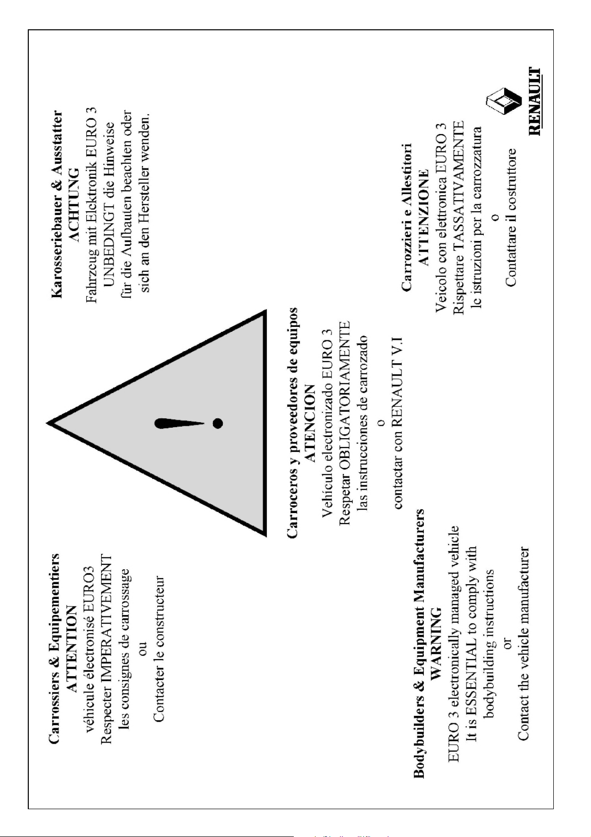
1.4 Warning . . . . . . . . . . . . . . . . . . . . . . . . . . . . . . . . . . . . . . . . . . . . . . . . . . . . . . . . . . . . . . . . . . . . .B7
2. GENERAL REMARKS ON THE “RENAULT PREMIUM” SERIES . . . . . . . . . . . . . . . . . . . . . . . . . . .B8
2.1 Identification of the vehicle . . . . . . . . . . . . . . . . . . . . . . . . . . . . . . . . . . . . . . . . . . . . . . . . . . . . .B8
2.2 General drilling principles . . . . . . . . . . . . . . . . . . . . . . . . . . . . . . . . . . . . . . . . . . . . . . . . . . . . .B10
2.2.1 Drilling cab panels for fitting accessories . . . . . . . . . . . . . . . . . . . . . . . . . . . . . . . . . . . . .B10
2.2.2 Drilling in sidemembers . . . . . . . . . . . . . . . . . . . . . . . . . . . . . . . . . . . . . . . . . . . . . . . . . . .B11
2.3 Precautions prior to welding . . . . . . . . . . . . . . . . . . . . . . . . . . . . . . . . . . . . . . . . . . . . . . . . . . .B12
2.3.1 Protection of wiring harnesses . . . . . . . . . . . . . . . . . . . . . . . . . . . . . . . . . . . . . . . . . . . . . .B12
2.3.2 Welding on vehicles equipped with an electromagnetic master switch . . . . . . . . . . . . . .B12
2.4 Minimum load on front axle . . . . . . . . . . . . . . . . . . . . . . . . . . . . . . . . . . . . . . . . . . . . . . . . . . . .B13
2.5 Soundproofing screens and heat shields . . . . . . . . . . . . . . . . . . . . . . . . . . . . . . . . . . . . . . . . .B13
2.5.1 Instructions for soundproofing screens . . . . . . . . . . . . . . . . . . . . . . . . . . . . . . . . . . . . . . .B13
2.5.2 Instructions for heat shields . . . . . . . . . . . . . . . . . . . . . . . . . . . . . . . . . . . . . . . . . . . . . . . .B13
2.6 Side impact beams . . . . . . . . . . . . . . . . . . . . . . . . . . . . . . . . . . . . . . . . . . . . . . . . . . . . . . . . . . .B13
3. INSTALLATION OF BODYWORK . . . . . . . . . . . . . . . . . . . . . . . . . . . . . . . . . . . . . . . . . . . . . . . . . .B14
3.1 Use of 1/20th scale drawings and calculation sheets . . . . . . . . . . . . . . . . . . . . . . . . . . . . . . . .B14
3.2 Example of a search . . . . . . . . . . . . . . . . . . . . . . . . . . . . . . . . . . . . . . . . . . . . . . . . . . . . . . . . . .B14
3.3 Body entrance dimension . . . . . . . . . . . . . . . . . . . . . . . . . . . . . . . . . . . . . . . . . . . . . . . . . . . . .B17
3.3.1 Behind-cab surrounds . . . . . . . . . . . . . . . . . . . . . . . . . . . . . . . . . . . . . . . . . . . . . . . . . . . . .B17
3.3.2 Body entrances with vertical exhaust . . . . . . . . . . . . . . . . . . . . . . . . . . . . . . . . . . . . . . . .B19
3.3.3 Presentation of the different air intakes . . . . . . . . . . . . . . . . . . . . . . . . . . . . . . . . . . . . . . .B20
3.4 Finishing of sub-frame entrance dimensions . . . . . . . . . . . . . . . . . . . . . . . . . . . . . . . . . . . . . .B21

RENAULT V .I. 06/01 4 DT 1/370
3.5 Sub-frame sections . . . . . . . . . . . . . . . . . . . . . . . . . . . . . . . . . . . . . . . . . . . . . . . . . . . . . . . . . .B23
3.5.1 Minimum height according to range of suspension movement . . . . . . . . . . . . . . . . . . . .B23
3.5.2 Sub-frame minimum inertia . . . . . . . . . . . . . . . . . . . . . . . . . . . . . . . . . . . . . . . . . . . . . . . . .B23
3.5.3 Discontinuous sub-frames (2-part) . . . . . . . . . . . . . . . . . . . . . . . . . . . . . . . . . . . . . . . . . . .B25
3.5.4 Continuous sub-frames . . . . . . . . . . . . . . . . . . . . . . . . . . . . . . . . . . . . . . . . . . . . . . . . . . . .B27
3.6 Attachment of bodywork . . . . . . . . . . . . . . . . . . . . . . . . . . . . . . . . . . . . . . . . . . . . . . . . . . . . . . .B27
3.7 Attachment of sub-frames to brackets . . . . . . . . . . . . . . . . . . . . . . . . . . . . . . . . . . . . . . . . . . . .B28
3.7.1 Day cab guiding and fastening zone . . . . . . . . . . . . . . . . . . . . . . . . . . . . . . . . . . . . . . . . .B28
3.7.2 Sleeper cab guiding and fastening zone . . . . . . . . . . . . . . . . . . . . . . . . . . . . . . . . . . . . . .B28
3.7.3 Vertical positioning of brackets . . . . . . . . . . . . . . . . . . . . . . . . . . . . . . . . . . . . . . . . . . . . .B30
3.7.4 Transversal positioning of brackets . . . . . . . . . . . . . . . . . . . . . . . . . . . . . . . . . . . . . . . . . .B30
3.7.5 Types of bodywork attachment . . . . . . . . . . . . . . . . . . . . . . . . . . . . . . . . . . . . . . . . . . . . . .B32
3.8 Longitudinal positioning of brackets on chassis . . . . . . . . . . . . . . . . . . . . . . . . . . . . . . . . . . . .B36
4. ELECTRICAL PRE-ARRANGEMENTS . . . . . . . . . . . . . . . . . . . . . . . . . . . . . . . . . . . . . . . . . . . . . .B52
4.1 Available power supplies . . . . . . . . . . . . . . . . . . . . . . . . . . . . . . . . . . . . . . . . . . . . . . . . . . . . . .B52
4.2 Electrical pre-arrangements . . . . . . . . . . . . . . . . . . . . . . . . . . . . . . . . . . . . . . . . . . . . . . . . . . . .B52
4.3 Management of engine speed . . . . . . . . . . . . . . . . . . . . . . . . . . . . . . . . . . . . . . . . . . . . . . . . . . .B57
4.3.1 Choice of engine speed by default . . . . . . . . . . . . . . . . . . . . . . . . . . . . . . . . . . . . . . . . . . .B57
4.3.2 Use of the steering wheel fast idling control . . . . . . . . . . . . . . . . . . . . . . . . . . . . . . . . . . .B58
4.3.3 Vehicle fitted with a power take-off . . . . . . . . . . . . . . . . . . . . . . . . . . . . . . . . . . . . . . . . . . .B58
4.3.4 Use of the chassis-mounted fast idling control . . . . . . . . . . . . . . . . . . . . . . . . . . . . . . . . .B59
4.3.5 Use of the chassis-mounted fast idling variable speed control . . . . . . . . . . . . . . . . . . . .B59
4.4 Electrical diagram for available power supplies . . . . . . . . . . . . . . . . . . . . . . . . . . . . . . . . . . . .B60
5. REFUSE COLLECTOR VEHICLE . . . . . . . . . . . . . . . . . . . . . . . . . . . . . . . . . . . . . . . . . . . . . . . . . .B66
5.1 Longitudinal positioning of brackets on chassis . . . . . . . . . . . . . . . . . . . . . . . . . . . . . . . . . . . .B66
5.2 Available power supplies at in cab on connection unit . . . . . . . . . . . . . . . . . . . . . . . . . . . . . .B68
5.3 Management of engine speed . . . . . . . . . . . . . . . . . . . . . . . . . . . . . . . . . . . . . . . . . . . . . . . . . . .B69
5.4 Speed limitation . . . . . . . . . . . . . . . . . . . . . . . . . . . . . . . . . . . . . . . . . . . . . . . . . . . . . . . . . . . . .B69
5.5 Electrical diagram for refuse collector vehicles available power supplies . . . . . . . . . . . . . . . .B70
6. HANDLING CRANES . . . . . . . . . . . . . . . . . . . . . . . . . . . . . . . . . . . . . . . . . . . . . . . . . . . . . . . . . . .B74
6.1 Handling crane with lifting torque outside graph limits . . . . . . . . . . . . . . . . . . . . . . . . . . . . . .B74
6.2 Handling crane in rear overhang . . . . . . . . . . . . . . . . . . . . . . . . . . . . . . . . . . . . . . . . . . . . . . . .B74
6.3 Plate mounting recommendations . . . . . . . . . . . . . . . . . . . . . . . . . . . . . . . . . . . . . . . . . . . . . . .B74
6.4 RENAULT PREMIUM behind-cab handling crane . . . . . . . . . . . . . . . . . . . . . . . . . . . . . . . . . . .B75
7.TIPPERS . . . . . . . . . . . . . . . . . . . . . . . . . . . . . . . . . . . . . . . . . . . . . . . . . . . . . . . . . . . . . . . . . . . . .B86
8.TANKERS . . . . . . . . . . . . . . . . . . . . . . . . . . . . . . . . . . . . . . . . . . . . . . . . . . . . . . . . . . . . . . . . . . .B88

DT 1/370 5 RENAULT V .I. 06/01
CHAPTER -C-
SUPPLEMENTARY INFORMATION ON THE “RENAULT PREMIUM”VEHICLE
1. MOUNTING OF POWER TAKE-OFFS . . . . . . . . . . . . . . . . . . . . . . . . . . . . . . . . . . . . . . . . . . . . . . .C3
1.1 Mechanical receiver . . . . . . . . . . . . . . . . . . . . . . . . . . . . . . . . . . . . . . . . . . . . . . . . . . . . . . . . . . .C3
1.1.1 Gearbox-mounted PTO . . . . . . . . . . . . . . . . . . . . . . . . . . . . . . . . . . . . . . . . . . . . . . . . . . . . .C3
1.2 Instructions for the assembly of auxiliary hydraulic pumps to ZF type “C” PTOs . . . . . . . . . . .C6
1.2.1 Supplementary instructions . . . . . . . . . . . . . . . . . . . . . . . . . . . . . . . . . . . . . . . . . . . . . . . . .C6
1.2.2 Calculation of the weight torque . . . . . . . . . . . . . . . . . . . . . . . . . . . . . . . . . . . . . . . . . . . . .C6
1.3 Access to gearbox . . . . . . . . . . . . . . . . . . . . . . . . . . . . . . . . . . . . . . . . . . . . . . . . . . . . . . . . . . . .C7
2. AIR-OPERATED EQUIPMENT . . . . . . . . . . . . . . . . . . . . . . . . . . . . . . . . . . . . . . . . . . . . . . . . . . . . .C8
2.1 Connection of extra auxiliary equipment . . . . . . . . . . . . . . . . . . . . . . . . . . . . . . . . . . . . . . . . . . .C8
2.1.1 Coupling for extra auxiliary equipment to chassis . . . . . . . . . . . . . . . . . . . . . . . . . . . . . . .C8
3. ELECTRICS . . . . . . . . . . . . . . . . . . . . . . . . . . . . . . . . . . . . . . . . . . . . . . . . . . . . . . . . . . . . . . . . . C11
3.1. Earths . . . . . . . . . . . . . . . . . . . . . . . . . . . . . . . . . . . . . . . . . . . . . . . . . . . . . . . . . . . . . . . . . . . .C11
3.1.1 Cab earths . . . . . . . . . . . . . . . . . . . . . . . . . . . . . . . . . . . . . . . . . . . . . . . . . . . . . . . . . . . . . .C11
3.1.2 Chassis earths . . . . . . . . . . . . . . . . . . . . . . . . . . . . . . . . . . . . . . . . . . . . . . . . . . . . . . . . . .C12
3.2 Passage of wiring harnesses and compressed air pipes . . . . . . . . . . . . . . . . . . . . . . . . . . . . .C15
4. CHASSIS . . . . . . . . . . . . . . . . . . . . . . . . . . . . . . . . . . . . . . . . . . . . . . . . . . . . . . . . . . . . . . . . . . .C15
4.1 Steel classes for sidemembers . . . . . . . . . . . . . . . . . . . . . . . . . . . . . . . . . . . . . . . . . . . . . . . . .C15
4.2 Sections of sidemembers . . . . . . . . . . . . . . . . . . . . . . . . . . . . . . . . . . . . . . . . . . . . . . . . . . . . . .C15
4.3 Reinforcement, extension, shor tening of sidemembers in the rear overhang . . . . . . . . . . . . .C16
4.3.1 Modification to the rear overhang . . . . . . . . . . . . . . . . . . . . . . . . . . . . . . . . . . . . . . . . . . .C16
4.4 Intermediate cross-member . . . . . . . . . . . . . . . . . . . . . . . . . . . . . . . . . . . . . . . . . . . . . . . . . . . .C17
5. CHANGING THE POSITION OF EQUIPMENT ON CHASSIS . . . . . . . . . . . . . . . . . . . . . . . . . . . . .C18
5.1 Rear run-under guard . . . . . . . . . . . . . . . . . . . . . . . . . . . . . . . . . . . . . . . . . . . . . . . . . . . . . . . .C18
6. HITCH COUPLING FOR DRAWBAR RIGID TRAILERS . . . . . . . . . . . . . . . . . . . . . . . . . . . . . . . . .C19
6.1 Mounting principle . . . . . . . . . . . . . . . . . . . . . . . . . . . . . . . . . . . . . . . . . . . . . . . . . . . . . . . . . . .C20
6.2 Rear bevelling of sidemembers . . . . . . . . . . . . . . . . . . . . . . . . . . . . . . . . . . . . . . . . . . . . . . . . .C21
6.3 Attachment of towing hook to 40-44 tonne and 50-60 tonne cross-member . . . . . . . . . . . . . .C22
7. ASSEMBLY OF EQUIPMENT TO CAB . . . . . . . . . . . . . . . . . . . . . . . . . . . . . . . . . . . . . . . . . . . . . .C24
7.1 Roof catwalk . . . . . . . . . . . . . . . . . . . . . . . . . . . . . . . . . . . . . . . . . . . . . . . . . . . . . . . . . . . . . . . .C24
7.1.1 Attachment of catwalk to day cab . . . . . . . . . . . . . . . . . . . . . . . . . . . . . . . . . . . . . . . . . . .C24
7.1.2 Attachment of catwalk to sleeper cab . . . . . . . . . . . . . . . . . . . . . . . . . . . . . . . . . . . . . . . .C25
7.2 Ladder . . . . . . . . . . . . . . . . . . . . . . . . . . . . . . . . . . . . . . . . . . . . . . . . . . . . . . . . . . . . . . . . .C26
7.2.1 Attachment of ladder to day cab . . . . . . . . . . . . . . . . . . . . . . . . . . . . . . . . . . . . . . . . . . . .C26
7.2.2 Attachment of ladder to sleeper cab . . . . . . . . . . . . . . . . . . . . . . . . . . . . . . . . . . . . . . . . .C27
7.3 Assembly of accessories on roof . . . . . . . . . . . . . . . . . . . . . . . . . . . . . . . . . . . . . . . . . . . . . . . .C28
7.3.1 Installation of antennae . . . . . . . . . . . . . . . . . . . . . . . . . . . . . . . . . . . . . . . . . . . . . . . . . . .C28
7.3.2 Installation of revolving beacons . . . . . . . . . . . . . . . . . . . . . . . . . . . . . . . . . . . . . . . . . . . .C28
7.3.3 Installation of air horns . . . . . . . . . . . . . . . . . . . . . . . . . . . . . . . . . . . . . . . . . . . . . . . . . . . .C29
7.3.4 Installation of roof deflector . . . . . . . . . . . . . . . . . . . . . . . . . . . . . . . . . . . . . . . . . . . . . . . .C30
7.3.5 Installation of frontview mirror . . . . . . . . . . . . . . . . . . . . . . . . . . . . . . . . . . . . . . . . . . . . . .C31
7.3.6 Installation of sunshade . . . . . . . . . . . . . . . . . . . . . . . . . . . . . . . . . . . . . . . . . . . . . . . . . . .C32
7.3.7 Installation of gantry . . . . . . . . . . . . . . . . . . . . . . . . . . . . . . . . . . . . . . . . . . . . . . . . . . . . . .C33
7.4 Fastening of accessories . . . . . . . . . . . . . . . . . . . . . . . . . . . . . . . . . . . . . . . . . . . . . . . . . . . . . .C34
8. AIRBAG . . . . . . . . . . . . . . . . . . . . . . . . . . . . . . . . . . . . . . . . . . . . . . . . . . . . . . . . . . . . . . . . .C35
8.1 Identification of a vehicle equipped with an airbag system . . . . . . . . . . . . . . . . . . . . . . . . . . .C35
8.2 Work on the vehicle (excluding the airbag) requiring precautions
to be taken to avoid inadvertent deployment of the airbag . . . . . . . . . . . . . . . . . . . . . . . . . . . .C35

RENAULT V .I. 06/01 6 DT 1/370

DT 1/370 A1 RENAUL T V.I. 06/01
CHAPTER -A-
GENERAL FEATURES

RENAULT V .I. 06/01 A2 DT 1/370
1. GENERAL FEATURES
1.1 Scope of liability
RENAULT V.I. vehicles are merchandized at the end of corroborated technical designwork and endurance tes-
ting, taking the various laws, regulations, standards… involved into consideration.
Modifications to a RENAULT V.I. vehicle for the fitting of bodywork and equipment should be carried out in
accordance with the rules and recommendations set out in this bodywork fitting guide and require an
“Agreement in Principle”, issued by the Product Applications Department.
Guarantee and responsibility
Any intervening party is responsible for his services in terms of guarantee and responsibility, including any dam-
age caused by his work and/or the equipment installed on-vehicle or the basic product.
In the event of RENAULT V.I. (or its network) being prime contractor for its own equipment (in relation to the end
customer), the guarantee is considered as being at least that of the warranty offered by RENAULT V.I. to its cus-
tomer.
Unless clearly specified otherwise in the order, the equipment warranty shall be negotiated directly between the
end customer and the equipment manufacturer.
The meeting of recommendations contained in the present document can in no way be considered as relieving
the equipment manufacturer’s responsibility, but simply as complying with the basic rules for professional trade
practice.
Any breach of these recommendations must be considered as shortcoming in respect of the rules and shall relieve
RENAULT V.I. of its liability in the event of damage connected directly or indirectly to such non-compliance.
All the equipment is considered to comply with these recommendations and shall not require any acceptance test-
ing upon delivery to check the conformity.
RENAULT V.I. guarantees non-modified original parts and components.
Interventions, conversions, adaptations of fittings carried out by the intervening par ty involves his responsibility,
even if they are authorized administratively (Conversion appendix II).
Such conversions must not under any circumstance lead to any impairment of the quality or of the primary func-
tions of the component elements of the vehicle (whether these elements are affected directly or not by the inter-
vention).
Any modification, changing of position of constituent vehicle parts or elements must be covered b y an “Ag reement
in Principle”, issued by the RENAULT V.I. Product Applications Department.
For further information or assembly agreement, contact:
TO OBTAIN ANY INFORMATION OR APPROVAL OF MOUNTING, PLEASE CONTACT:
For France:
SERVICE TECHNICO-COMMERCIAL
RENAULT V .I.
API. COM 00A 238
69806 ST PRIEST CEDEX
Tel.: 04 72 96 68 14
Telex: 300 265 UDCF +
Fax:04 72 96 81 93
1.2 Regulations
The bodybuilder must meet:
— the different European and/or destination country laws, regulations and standards governing dr iving and
vehicle building,
— the stipulations of the highway code and its various amendments and appendices,
— the different laws, regulations and standards governing road traffic in force in the country of destination.
For the United Kingdom:
Product Applications Department
RENAULT V.I. UNITED KINGDOM LIMITED
Boscombe Road,
Dunstable
Bedfordshire LU5 4LX
Tel. (Switchboard): (+44) (0)1582 471 122
Fax (Marketing) (+44) (0)1582 479 146

DT 1/370 A3 RENAUL T V.I. 06/01
The scope of this compliance must cover:
— Lighting and signalling,
— Weight and dimensions,
— The field of vision and rear view,
— The regulation protection devices (e.g. side beams, anti-spray, run-under guard),
— The hitch coupling and towing systems, (compliance with standards and regulations),
— Specific clauses concerning the transport of dangerous goods (ADR, COSHH etc.),
— Sun-roofs,
— Pollution control standards,
— Electromagnetic compatibility standards for electronic equipment.
1.3 Safety
All components having an influence on:
— The control of the driver of the trajector y and the ability to stop the vehicle and its trailer,
— The load distribution on the front or the rear, the left or the right,
— The risk of fire,
— and any other risk for the vehicle and its surrounding environment.
Among the components, we would mention, among others:
— The cab tilt mechanism,
— The wheels (tightening of the bolts),
— Seats and seat belts (anchorage points),
— The attachment of bodywork or equipment to be in conformity with the technical instruction document in force,
(i.e. the Guide for the Fitting of Bodywork),
— The hitch coupling and towing systems, (i.e. anchorages),
— Electrical systems (protection of circuitry, the electrical rating, attachment, conformity of the connections with
the technical instruction document, (i.e. the Guide for the Fitting of Bodywork),
— Warning systems and dr iver information systems, (i.e. no interference with the information given by the instru-
ment panel on the dashboard),
— Information for use affixed by the manuf acturer to the vehicle (i.e .decals for tilting of the cab, drilling points, wel-
ding points, batteries, etc.)
— Extension and reduction of the length of the wheelbase and the rear overhang.
— Re-location or replacement of the crossmembers.
— Circuits for ancillary equipment.
In order to guarantee the safety and the satisfactory operation of the vehicle, modification of the follo-
wing components is strictly forbidden:
— Brakes: circuits, controls and anchorages,
— Steering: circuits, controls, anchorages and geometry,
— Axle and axle housing assemblies,
— The air-bag system and pretensioning systems on the seat belts,
— The electronics.

RENAULT V .I. 06/01 A4 DT 1/370
1.4 Quality assurance
Our permanent objective is to give satisfaction to our customers and we must achieve this in full on the final
product consisting of a chassis, bodywork and/or an item of equipment.
In order to achieve this objective, RENAULT V.I. expects from all those co-operating with it in the field of
mounting bodywork and equipment supply to implement a Quality Assurance System.
RENAULT V.I. can demand proof for the execution of all bodywork, the fitting of equipment or modification of
a basic truck, in accordance with Standard ISO 9000, of:
— The conformity with all legislation, EC Directives and national regulations,
— The compliance with the manufacturers’ directions,
— The control of quality of the execution of the work.
This is done with the knowledge that, on the face of it, the vehicle is considered as complying with the
whole of the regulations.
1.5 Documentation
In all cases involving equipment, the installer is obliged to supply a manual covering the use, service, main-
tenance and safety of his installation.

Tension aux bornes de l’accumulateur
batterie 6 Volts batterie 12 Volts
arge
6,3 Volts 12,7 Volts 1,27 100 %
6,2 Volts 12,5 Volts 1,24 80 %
DT 1/370 A5 RENAUL T V.I. 06/01
1.6 General instructions
When building and fitting a body (including such equipment as rear run-under guards), a certain number of
requirements and a certain number of vital requirements specific to each type of vehicle must be taken into
consideration.These various points relate to maintenance, accessibility and the circulation of fluids.
Examples:
— Ease of access to the various maintenance and lubrication points, to the fuel tank and fuel gauge, to the
batteries and the various electrical terminal boxes.
— The ability to easily dismantle the various component par ts of the transmission and the suspension.
— Access to the circuits for air-intake, exhaust, and fuel supply.
— Taking into account the wheel movement detailed on the bodywork drawing (i.e.take care to allow for snow
chains; extra clearance must be provided).
— Ventilation of the brake drums and discs and the batter y compar tment.
— The radiator inlet and outlet areas, which must not be modified.
— Complete compliance with the dimensions and weights specified in our technical documents. Under all cir-
cumstances, the bodybuilder must ensure free movement and safe operation of all the moving component
parts of the chassis (i.e. spr ings, prop shaft, etc.)
— The addition of a body must not affect the vehicle running and driving safety. Take care to ensure that a
balanced distribution of the loads on the right and the left hand sides of the vehicle is obtained.
— For any bodywork installation, a calculation of load distribution must be made for each axle, in order to check
that the weight imbalance between the right and the left hand side is below 4%.
— The flow of the coolant must be maintained at all times. It is, therefore, not allowed to blank off, even par-
tially, the air intakes provided (on the radiator grille or the front end). Orange ADR or similar “Hazardous
Substances” plates should be affixed to solid surfaces (i.e. without vent holes).
On the arrival of a vehicle in your workshop for body fitting, we recommend that you should check one hour
after the arrival of the vehicle, the state of charge of the batteries.
During the period for the fitting of the bodywork, you should particularly check that:
— The vehicle is not run without a batter y.
— Do not move the vehicle on the starter motor.
— Do not use a booster starter.
— Ensure that the tyre pressure is checked and tyres inflated to the correct value where necessary.
— Protect body components or items of trim against all damage.
— Refit the original batteries, where these have been taken off.
IMPORTANT
— Whatever work you are doing on the vehicle, you must switch off the electrical circuit at the master switch or
by disconnecting the batteries in order to avoid any risk of electric shock during work.
— When a vehicle is laid up (i.e.at a standstill for longer than 10 days), disconnect the electrical circuit by remo-
ving the fuse or by the circuit-breaker so as to avoid discharge of the batteries through the tachograph.
Voltage at the battery terminals
Specific gravity
of the electrolyte
State of charge
6 V olt battery 12 V olt battery
6.3
6.2
12.5
12.7
1.24
1.27

RENAULT V .I. 06/01 A6 DT 1/370
The information contained in this manual is only applicable to bodywork in steel. For aluminium bodies, refer
to the Product Applications Department of RENAULT V.I.
It is forbidden to weld, grind, cut up, drill or heat the sidemembers or crossmembers unless the contrar y is
clearly stated. These operations may only be carried out in conformity with the recommendations laid down
in the present document.
Any special case, any bodywork fasteners and fittings not described in this manual must be submitted for our
approval prior to use.
Before commencing the fitting of any bodywork, you must consult:
— The V ehicle Technical Data Sheet,
— The bodybuilders drawing and the relevant calculation sheets which relate to the body to be fitted,
— The vehicle driving and maintenance handbook.
If you do not have these items available, you should obtain them from RENAULT V.I. Dealers or the Product
Applications Department.
In the technical manual and on the bodywork drawing is stated the permitted maximum and minimum length
of body; we would strongly advise you to stay within these limits.
Furthermore, it should be noted that the changing of position of a component such as spare wheel, tank, etc.,
the modification of a chassis without uniform weight distribution or the fitting of an over-cab extension, causes
a modification of the load distribution of a fully equipped chassis in every single case.
Modification to load distribution must be compensated for by an alteration in the permitted length for body-
work. It then becomes necessar y to calculate the new position of the centre of gravity of the bodywork.
The weights specified in our technical data sheets refer to standard vehicles , ready f or the road, without optio-
nal extras.
Furthermore, the weight of chassis cab is given with a tolerance of plus or minus 4%.
Optional equipment such as reinforced springs, power take-offs, different tyre fitments, will cause an increa-
se in weight for the basic chassis.
For these reasons, when weighing the chassis cab, bodybuilders should weigh:
— The front axle(s),
— The rear axle(s),
— The complete vehicle,
without driver, without passenger, but with full fuel tanks and with vehicle on-board tool kit.
For the preparation and attachment of the various types of bodywork, it is pref erab le not to take off the wheels ,
unless absolutely necessary.
Nevertheless, you must take the precautions set out below:
— It is forbidden to paint the bearing surfaces of the wheel rim hubs and the seating for wheel nuts.
— During fitting, make certain that the par ts are perfectly clean prior to fitting.
— Tighten the wheel nuts to the torque recommended (cf. vehicle driving and maintenance handbook)
Installation fitted with keys: the section of such keys must be very different to that used for the vehicle keys.
Indeed, these keys should not be able to be put into the vehicle locks by mistake, thus avoiding any risk of
damage to the barrels of the locks.
1.7 Safety on tilt cabs
After the conversion of standard cabs by the bodybuilders, (i.e. extension, bunk adaptation, over-cab exten-
sion, etc.) because the weight distribution has changed, the tilt system may no longer meet the requirements
of the safety standards.
Under these circumstances, and without prior agreement from the manufacturer, the full and entire responsi-
bility rests with the bodybuilder.
1.8 Chassis markings
The identification number of the vehicle is on the sidemember (refer to the vehicle driving handbook).
The identity markings of the vehicle must remain visible and accessible without having to remove any part of
the body.

DT 1/370 A7 RENAUL T V.I. 06/01
1.9 Adjustments to the vehicle settings
Under no circumstance may bodybuilder or converters make any alteration to the original settings of
RENAULT V.I. vehicles.
1.10 Cleaning
1.10.1 Bodywork
So as not to cause any damage to the condition of the paintwork and the seals:
— Avoid using a high temperature jet of steam.
— Restrict the use of brushes.They must be in good condition and well maintained.
— We advise against the use of brushes, during the first month of vehicle use.
— If you are using a high pressure jet wash unit, limit the pressure to 80 bars maximum.
— Keep the lance well away from the bodywork; do not spray fluidtight joints.
— Use neutral soap based products.
— In order to remove grease spots, use cleaning fluid (not petrol).
— Par ts in aluminium must be cleaned with water to which a non-alkaline washing product has been added,
and rinsed with clean water.
— Spread a coat of Vaseline or talcum powder over the seals.
1.10.2 Chassis/Underbodies
Use a high pressure unit. Limit the pressure of the jet to 80 bars maximum and the time of use to the strict
minimum necessary.
In order to prevent any risk of a problem, do not spray:
— electronic or electrical boxes,
— the seals of link rods,
— hinge pins,
— air inlets for the heater, the engine air intake and air filter,
— pneumatic and electrical apparatus,
— absorbent materials and soundproofing screens,
— the fuel gauge.
1.10.3 Cleaning of the cab
Spray lightly or use a cloth dipped in a cleaning agent (i.e.soapy water, methylated spirits, etc.).Products with
a petroleum and trichlorethylene base are not to be used.
Spread talcum powder lightly onto the door seals and the windows, as well as any link rods.
1.10.4 Cleaning of the instrument panel
Only use soapy water. Any other product is not allowed.
1.11 Safety and protection of components
Before any operation of grinding, drilling, or welding, ensure that the following are effectively protected or
taken off:
— Plastic pipework and tubes,
— Electrical wiring harnesses,
— Suspension springs (particular ly for the protection against corrosion),
— The bags for the air suspension,
— The soundproofing screens,
— Any other component sensitive to heat, to the discharge of incandescent matter, to ultraviolet rays (i.e.elec-
tronic control units, electronic components, items in plastic material, flexible anti-vibration mountings, pain-
ted items, etc.)
— For welding work, comply with the other recommendations described in the chapter entitled “Protection of
electrical and mechanical components”.

RENAULT V .I. 06/01 A8 DT 1/370
1.12 Summary of definitions
Maximum body length (Dimension W on technical data sheets and bodywork drawings).
This is the bracket of lengths for bodies (not including fittings and accessories) worked out in relation to the
extreme positions of a given centre of gravity for a load which is taken to be evenly distributed and taking into
account the space which must be left to the aft of the cab, laid down by the manufacturer, and the maximum
permitted loads per axle on a chassis cab without options.
Body entrance (Dimension B on technical data sheets)
Minimum distance between the front axle centre-line and the front end plane of the body.
Load distribution calculations
Comply with the regulatory constraints for each country and the load limits given per axle for each model by
RENAULT V.I.
We remind you that these values are given for uniformly distributed loads.
The lateral imbalance of the loads should not exceed a maximum of 4% between the LH and RH roadwheel
of each axle.
Chassis rear overhang (Dimension N on technical data sheets)
Horizontal distance between the centre-line of the rear roadwheels and the rear extremity of the body (exclu-
ding fittings and accessories).
In the case of vehicles with 3 or 4 axles: distance between the centre-line of the rearmost axle and the extre-
mity of the chassis.
Body rear overhang (Dimension X on technical data sheets)
Horizontal distance between the centre-line of the rear roadwheels and the rear extremity of the body (exclu-
ding fittings and accessories).
In the case of vehicles with 3 or 4 axles: distance between the technical centre-line of the tandem and the
rear extremity of the body.
Wheelbase (Dimension F or F’ on technical data sheets).
Distance between the centre-lines of the front and rear roadwheels (vehicle laden).
In the case of vehicles with 3 or 4 axles: distance between the centre-line of the front roadwheels and the
centre-line of the foremost rear axle — for calculations take dimension F’ (technical wheelbase).
Tandem
Solely in the case of vehicles with 3 or 4 axles: the 2 rear axles taken together, regardless of whether they
are driving axles or trailing axles.
Maximum axle weight
Carrying weights are stipulated on each axle for each type of vehicle.These values are indicated on the tech-
nical data sheets and on the VIN plate and must be complied with on all v ehicles fitted with bodies when laden
and when empty.
Driver and cab passengers weight
The weight of the driver and passenger (passengers) in the cab is applied to the front axle in the case of a
forward control cab.
For cabs of the semi-forward control type, 2/3 of the weight should be applied to the front axle and 1/3 to the
rear axle.
Weight of driver or each passenger: 75 kg (calculated on the basis of the cab seating capacity), unless sti-
pulated otherwise: i.e. Export, Army, Fire Brigade, etc.
For cabs with a seating capacity of more than 3 persons, calculate the weight distribution of the persons on
the basis of the seats layout.
For equipment intended for the Army or for Civil Administrations, take the specific specifications into account.

DT 1/370 A9 RENAUL T V.I. 06/01
1.13 Certificate of approval of the conversion of a vehicle
1.13.1 Application for approval
1 If the body or the equipment fitted do not modify the weight and dimensional characteristics of the chas-
sis entered in the descriptive sheet, the vehicle can be submitted to the Type Approval Department without
any action by RENAULT V.I. being necessary (within the permitted limits in force).
2 The maximum rear overhang is equal to 60% of the wheelbase.However, for special cases, we can grant
higher percentages — for this, consult us.
3 If the layout requires modification to the wheelbase, it is essential to consult the Product Applications
Department. Each case has to be covered by a specific design.
4 The certificate will be issued in accordance to the legislation in force regarding modifications made by and
under the responsibility of the bodybuilder, within the limits stipulated by the Manufacturer and relative to:
— the wheelbase
— the distribution of loads
— the cab characteristics.
5 For more accuracy in your calculations, we recommend you to introduce into the data the weighed weight
of the chassis cab to be equipped (capable of varying according to manufacturing tolerances and the
various options available). The same applies to equipment for which the manufacturers can accurately
define the weight and the position of the centre of gravity.
1.13.2 Body fitting certificate
This defines the installation of the equipment on the chassis cab and the unladen weight imposed on the axles
and then the weight when fully laden.
It must be attached to all applications relating to the equipment which do not comply with any of the dimen-
sions set out in the descriptive sheet.
1.13.3 Responsibility for installation
The building and fitting of a body on a vehicle is the sole responsibility of the bodybuilder, who must comply
with the recommendations in the present document.
He must ensure that the installation of the body does not affect the functions or the reliability of the compo-
nents or the road behaviour of the vehicle.

RENAULT V .I. 06/01 A10 DT 1/370
1.14 Painting
1.14.1 Precautions
— Protect the RENAULT V.I. equipment (i.e. by using screens, self-adhesive tape, cab cover etc.)
— Never put vehicles into drying ovens at a temperature of more than 80° C.
— The chassis of the vehicle must be electrically earthed to allow static electricity to run away to earth (protec-
tion of electronic boxes).
— The vehicle must be protected against corrosion by paints compatible with those used by our Company and
conforming to RENAULT V.I. Specification No 4702 441 (protection of bodywor k and equipment adapted to
RENAULT V.I. vehicles) available from the Product Applications Department.
— Thinner solvents must never be used on cables and electrical sheaths.
— Protect the identification marking of electrical wires and compressed air pipes.
Never paint bearing surfaces of brake drums and disc wheels, or with twin tyre fitment, the assembly surfaces
between the disc wheels. As a general rule, do not repaint the support surfaces of original fitment nut and bolt
hardware and comply with the specification.
NOTE
Our Product Applications Department holds the reference numbers for paint colour shades for chassis and cabs
at your disposal.These paint colours can be procured as “spare parts” and can be ordered from our dealers.
The cab colour shade is indicated on the front end of the cab.
Since 1994, chassis and accessories are no longer sprayed with the customer’s shade of paint at the time of ori-
ginal fitment.
To preser ve the aspect and original quality, it is essential to observe the following methods after fitting equip-
ment, body, sub-frames and various adaptations to major units or chassis frame:
1.14.2 Major units (gearboxes, drive axles, engines, axles, etc.)
Works paint: GLYCEROPHTHALIC
Retouch (after fitting PTO, charge indicator, etc.)
Retouch method
— Clean with a universal cleaner or using a high-pressure cleaner.
— Wipe down, then apply a primer.
— Let the product cure until mat (about 15 minutes at 20° C), then apply the corresponding polyurethane lacquer.

DT 1/370 A11 RENA UL T V.I. 06/01
1.14.3 Chassis frame and accessories (sidemembers, crossmembers, fittings, lockers,
etc.)
Works paint: POLYURETHANE or POLYESTER powder.
Retouch method:
Superficial scratches (the metal is not affected).
— Clean with a universal cleaning product.
— Wipe down, then apply the corresponding undiluted b ut catalyzed polyurethane lacquer, using a small brush.
Deep and fine scratches (down to the bare metal).
— Clean with a universal cleaning product.
— Wipe down, then apply the primer, using a small brush.
— Let the product cure (about 15 minutes at 20° C), then apply the corresponding undiluted but catalyzed poly-
urethane lacquer.
Deep and wide scratches (down to the bare metal, drilling of sidemembers for attaching tail lifts and acces-
sories) due to drilling.
— Rub down.
— Clean with a universal cleaning product.
— Let the product cure until mat (about 15 minutes at 20° C), then apply the corresponding polyurethane lac-
quer.
Making good after conversion (after converting wheelbase and overhang).
— Grind, rub down; prepare the area in question (bur nt paint, welding scale, etc.).
— Clean with a universal cleaning product or using a high-pressure cleaner.
— Mask with tape (electrical wiring harnesses, air and fuel pipes, labels, etc.)
— Wipe down, then apply the primer.
— Let the product cure until mat (about 15 minutes at 20° C), then apply the corresponding polyurethane lac-
quer.
— After drying, put back the electrical wiring harnesses, air and fuel pipes and accessories.
Spraying chassis and accessories (with customers colour shade).
— The bodybuilder undertakes to preserve the aspect and quality of the original fitment vehicle (except for nut
and bolt hardware).
— Clean with a universal cleaning product or using a high-pressure cleaner.
— Mask with tape (electrical wiring harnesses, air and fuel pipes, labels, etc.)
— Wipe down, then apply the primer.
— Let the product cure until mat (about 15 minutes at 20° C), then apply the corresponding polyurethane lac-
quer.
— After drying, put back the electrical wiring harnesses, air and fuel pipes and accessories.
NOTE
All spray gun operations are to be carried out in a painting booth.
Since August 1999, the chassis are painted grey as replacement for Enduro red. For paint retouches on grey
chassis, use a grey paint aerosol ref. N° 50 01 848 147.

Finish paint
Two-component polyurethane paint and corresponding thinner.
1.14.4 Ingredients
Nettoyage manuel
Nettoyant universel, nettoyant équivalent, solvant.
Produits homologués RENAULT V.I.
Fournisseur Appellation commerciale Réf. RENAULT V.I. Réf. fournisseur
BASF PK 900 50 01 821 758 SV 20023F
ICI AUTOCOLOR Slow Spirit Wipe 50 01 854 983 P850–1402
STANDOX Agent ENTFERNER 50 01 825 985 FA 931 2002
Nettoyage haute pression
Dégraissant, dégraissant phosphatant
Apprêtage
Produits homologués RENAULT V.I.
Fournisseur Appellation commerciale Réf. RENAULT V.I. Réf. fournisseur
STANDOX apprêt “EPOXY”
durcisseur “EPOXY”
diluant “EPOXY”
diluant lent “EPOXY”
diluant 2KS
50 01 826 019
50 01 825 990
50 01 826 005
50 01 829 256
50 01 825 992
FA 931 5203
FA 931 5204
FA 931 5205
FA 931 5213
FA 020 7810
ICI AUTOCOLOR apprêt “EPOXY”
durcisseur “EPOXY”
diluant
50 01 829 477
50 01 829 480
50 01 829 481
P580–2100
P210––833
P850–3091
RENAULT V .I. 06/01 A12 DT 1/370
1.14.4 Recommended products
Manual cleaning
Universal cleaning product or equivalent solvent
Products approved by RENAULT V.I.
High-pressure cleaning
Degreaser, phosphater degreaser
Filing and sealing
Products approved by RENAULT V.I.
“EPOXY”filler-sealer
“EPOXY”hardener
“EPOXY”thinner
“EPOXY”slow thinner
thinner 2KS
“EPOXY”filler-sealer
“EPOXY”hardener
thinner
Supplier Commercial name RENAULT V .I. Ref. Supplier Ref.
Supplier Commercial name RENAULT V .I. Ref. Supplier Ref.
ENTFERNER Agent

> A B – C D <
Variante du polymère de base
Séparateur
Désignation des charges et renforts
Pourcentage de charges
Terme abrégé du ou des polymères
DT 1/370 A13 RENA UL T V.I. 06/01
1.14.5 Marking of polymer components (recycling of plastics)
Plastic parts are marked so as to simplify their sor ting dur ing recycling at the time when the vehicle is scrap-
ped at the end of its life.
Marking of the plastic parts is done by placing abbreviated terms for the polymer components between the
symbols “>“ and “<“.The parts are marked on a face which the customers cannot see and when it is possible
the marking is indelible. Marking is done in the following manner:
Marking of single component products
The abbreviated term for the material is enclosed in symbols “>“ and “<“.
For example:“>PP<“ or “PP” indicates polypropylene.
Marking of copolymers
The abbreviated terms for the polymers are separated by a “/”.
For example:“>P/E<” indicates the copolymer propylene ethylene.
Marking of mixtures or blends of polymers
The abbreviated terms are separated by a “+” (heterogeneous structure).
For example:“>PP + EPDM<“ stands for a blend of polypropylene and EPDM.
Marking of polymers with fillers (additives)
The abbreviated term for the polymer is separated from that for the filler by a dash “—”.
The number following the abbreviated term for the filler relates to its percentage in the mixture.
For example:“>PA66 — (GF25 + MD15)<“ indicates polyamide 66 with 25% filler and 15% reinforcement with
mineral fillers (in decreasing order of percentage).
Marking of multi-component products
The abbreviated terms for the components are separated by commas, in order of appearance (firstly the
surface material).
For example:“>PVC, PUR, ABS<“ indicates skin surface PVC on PUR foam with an ABS insert.
Marking of special features
Abbreviated terms for the polymers can be added up to 4 symbols, in order to indicate a modification.
The symbols are put in after the abbreviated terms.
For example:“>PE — C<“ indicates chlorinated polyethylene, “>PE — LLD” stands for linear low density
polyethylene.
Abbreviation for the polymer(s)
Variant of the base polymer
Separator
Designation of the fillers and additives
Percentage of fillers

Tableau des principaux polymères
Terme abrégé
Variante Matériaux
A.B.S Acrylonitrile/butadiène/styrène
A.S.A Acrylonitrile/styrène/acrylate
E/P Ethylène/propylène
E.P.D.M copolymère éthylène/propylène/diène
P.A Polyamide
P.A 6 Polyamide 6
P.A 66 Polyamide 66
P.C Polycarbonate
P/E Propylène/éthylène
P.E Polyéthylène
P.E – HD Polyéthylène haute densité
P.E – LD Polyéthylène basse densité
P.E – LLD Polyéthylène linéaire basse densité
P.E – X Polyéthylène réticulé
P.M.M.A Poly(méthacrylate de méthyle)
P.O.M Polyoxométhylène
P.P Polypropylène
P.P.E Poly(phénylène éther)
P.P.O.X Poly(oxyde de propylène)
P.S Polystyrène
P.S – HI Polystyrène choc
P.T.F.E Poly(tétrafluorométhylène)
P.U.R Polyuréthanne
P.V.C Polychlorure de vinyle
P.V.C – C Polychlorure de vinyle chloré
P.V.C – P Polychlorure de vinyle plastifié
RENAULT V .I. 06/01 A14 DT 1/370
Abbreviated term Variant Materials
Acrylonitrile/butadiene/styrene
Acrylonitrile/styrene/acrylate
Ethylene/propylene
Copolymer ethylene/propylene/diene
Polyamide
Polyamide 6
Polyamide 66
Polycarbonate
Propylene/ethylene
Polyethylene
High density polyethylene
Low density polyethylene
Linear low density polyethylene
Cross-linked polyethylene
Poly(methacrylate of methyl)
Polyoxomethylene
Polypropylene
Poly(phenylene ether)
Poly(oxide of propylene)
Polystyrene
Impact polystyrene
Poly(tetrafluoroethylene)
Polyurethane
Polyvinyl chloride
Chlorinated polyvinyl chloride
Plasticized polyvinyl chloride
Table of the principal polymers

DT 1/370 A15 RENA UL T V.I. 06/01
1.15 Electrical equipment
1.15.1 General
— Any mounting of a specific item of equipment on a commercial vehicle must be in conformity with the recom-
mendations of RENAULT V.I. and the legislation in force. Its execution remains the entire responsibility of the
bodybuilder, both with regard to the suitability for the vehicle being equipped and any possible electromagnetic
interference.
— For reference to wiring diagrams, consult the electrical equipment workshop manual for the vehicle (available
from the Spare Parts Department of RENAULT V.I.).
— Check that the electrical consumption of this equipment is appropriate for the capacity of the batteries and also
the charging current rate of the alternator (if not, refer to the recommendations of the manufacturer CIC 1081).
For the fitting of any particular equipment, consult the Product Applications Department of RENAULT V.I.
— A schematic diagram should be submitted for the approval of RENAULT V.I., when raising any specific question.
— A wiring diagram for the bodybuilder’s or equipment manufacturer’s installation must be incorporated into the
vehicle driving and maintenance handbook.The electrical connection points for the equipment being supplied
should be clearly and precisely indicated on this wiring diagram (even after the agreement of RENAULT V.I. has
been obtained).
— Follow the electrical protection recommendations of RENAULT V.I.; it is forbidden to change the rating of fuses.
— In order to harmonize vehicle equipment, you should use in preference such items as are identical to those fit-
ted in the basic vehicle (i.e.indicator lamps, controls, relays, etc.).
— Assembly of a protective shield on the electric retarder is compulsory for ADR (Transport of Hazardous
Substances) vehicles (refer to regulations in force).
— It is compulsory for the supply voltage for the equipment installed to be equal to the rated v oltage of the vehicle.
The installation of equipment with a 12 volt power rating on our vehicles (24 volt rated voltage) is not permitted
unless a voltage dropper is added.
— Under the circumstances that additional lamps are fitted, the installation must not damage the fluidtight sealing
of the junction boxes.
— Operating without a battery is forbidden.
1.15.2 Wiring harnesses
— Use to the full the wiring runs already set up by the manufacturer (i.e. conduits, tubes, sleeves, etc.) and com-
ply with the limit of their capacity.
— Any wiring harness added by the bodybuilder must be protected by a sealed sheath (smooth and thick or rin-
ged) and can be routed along with the original wiring runs for the vehicle provided that it does not adversely
affect the mechanical mountings for the original harnesses. For vehicles for the transpor t of hazardous goods,
use the protective equipment authorized by the regulations covering the transpor t of hazardous goods.
— If you are obliged to route wires close to a source of heat (i.e.engine, exhaust system, etc.), the minimum clea-
rance to be complied with is 200 mm.
— Never route a wiring harness over projecting angles.
— Never attach a wiring harness to moving parts (even slight movement).
— The section of the cables being used must be suitable for the use in question. Their cross-section should be
selected in accordance with the maximum current on-line (5 amperes per mm2).
— The length of the wiring harnesses should be long enough to allow the electrical appliance which is connected
to be taken off (i.e.principal display unit, tachograph, etc.).
— The numbering of the wires must be in accordance with the manufacturer’s standard.
— The link between the sheath and the connector must be fluidtight.

RENAULT V .I. 06/01 A16 DT 1/370
1.15.3 Electrical connections
— Any additional connection requires protection that is suitable for the use for which it is intended (even if the
power supply provided for the customer by RENAULT V.I. is already protected by a fuse).
— Any electrical connection must be properly wired on the power lines supplied by the manufacturer to the
bodybuilder’s equipment (refer to the servicing and maintenance handbook for the vehicle in question).
— Tapping into the various wiring harnesses supplied by RENAULT V.I. is completely FORBIDDEN (for
example vehicle rear lamps, external marker lamps, contactors, pressure switches, relays, electronic box
inputs and outputs, etc.)
Reminder: a 12 V tapping at the middle point between the two batteries is str ictly FORBIDDEN.
— The electrical connections of the various wiring har nesses of the bodybuilder must be made using a fluid-
tight junction box or otherwise using sealed connectors.If connections have to be made on circuits hooked
up to electronic equipment:
— Ensure that you comply with the polarity recommended.
— No inductance current must pass through the circuits which have been added.
— All the earths must be connected up to the available “EARTH” points provided and not to the bodywork of
the vehicle.
— After work on junction boxes, the seal must always be as integrally effective as the original seal.
— Any power supply requiring a direct connection to the batteries must be capable of being isolated by a bat-
tery cut-out (for example:tail lifts) and protected by a fuse sited as near as possib le to the batteries.Suitable
connection terminals should be used.
— The + power supply is taken from the master switch, or failing this, from the battery terminal for vehicles
without a master switch, but in no case from the alternator or starter motor terminal.
— Power supplies to auxiliary equipment:i.e. telephone, fax, etc.The quality of the installation is the responsi-
bility of the installer (i.e. reception, static, interference, etc.)
— Preferably, you should use connectors approved and distributed by RENAULT V.I. (i.e. type, sealing proper-
ties, rating, number of channels, etc.)
— Connectors for equipment should be positioned near the bottom, whilst avoiding areas subject to splashing
(i.e. wheelarches, etc.).
1.15.4 Available power supplies
All our vehicles are equipped with the available power supply protected by fuses and these are at the dispo-
sal of bodybuilders and equipment manufacturers.
These power supplies are described in the vehicle driving and maintenance handbook (supplied with every
vehicle), in the Workshop Repair Electrical Manual, and in this document (all these documents are available
from the RENAULT V.I. dealer network).
1.15.5 Flasher units
Should the flasher unit become inoperative due to failure to comply with the instructions contained in this
document, the coverage granted by the warranty will be lost.
The flasher units are designed for a maximum rating which is marked on the unit.
Do not exceed this power rating.
Connection
In order to make the connections correctly, consult either the identification mar ks which are located close to
the terminals, or the wiring diagram on the label which is affixed to the flasher unit cover.
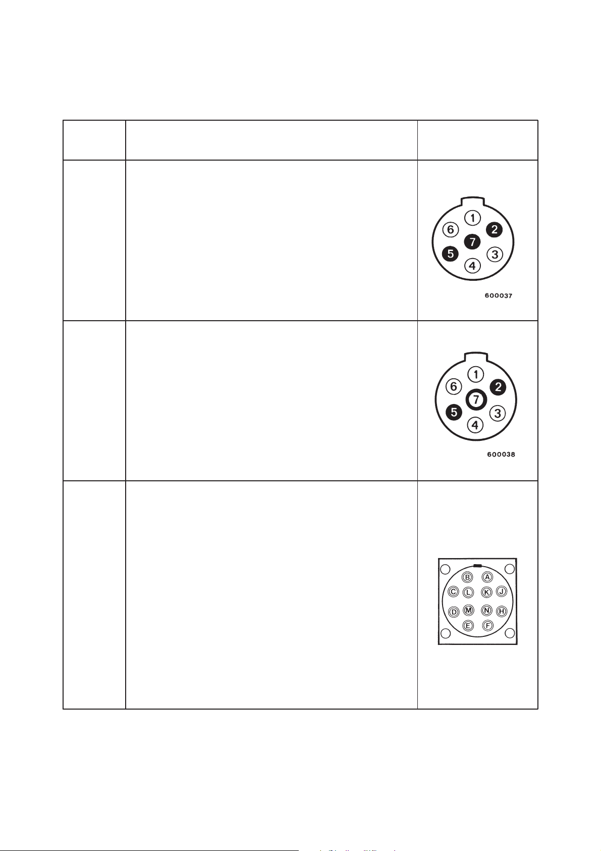
1.15.6 Tableaux récapitulatifs des prises de courants normalisees
12 Volts Socle type 12 N
(Norme – BNA.R.43.407 d’Avril 1982
– ISO 1724)
1 – Feux indicateurs de direction gauche
2 – Feu arrière de brouillard
3 – Masse
4 – Feux indicateurs de direction droit
5 – Feux de position arrière et encombrement droit
et éclairage plaque d’immatriculation
6 – Feux de stop
7 – Feux de position arrière et encombrement gauche et
éclairage plaque d’immatriculation
TENSION DESIGNATION ET NORME SCHEMA DU SOCLE
(vue de face)
12 Volts Socle type 12 S
(Norme – BNA.R.43.410 d’Août 1984
– ISO 3732)
C’est un socle supplémentaire qui se monte en plus du
socle 12 N.
1 – Feux de recul
2 – Sans affectation
3 – Masse
4 – Alimentation “+” supplémentaire
5 – Contrôle par mise à la masse
6 – Alimentation “+”
7 – Sans affectation
24 Volts Socle 12 broches
(Norme – BNA.R.43.405 de Mars 1961
– DEFA 1457 b
– DCEA 5.556.
– NATO)
A –Feu de position gauche black–out
B –Feux indicateurs de direction gauche
C –Feu de position droit black–out
D –Masse
E –Feux de position arrière, encombrement et éclairage
plaque d’immatriculattion
F – Feux de stop black–out
H –Sans affectation
J – Feux indicateurs de direction droit
K –Alimentation “+” batterie
L – Masse
M –Feux de stop
N –Sans affectation
DT 1/370 A17 RENA UL T V.I. 06/01
1.15.6 List of standard power sockets
SUPPLY
VOLTAGE
DESCRIPTION AND STANDARDS
12 N type socket
(Standard: — BNA.R.43.407 dated April 1982
— ISO 1724).
1 — LH direction indicator lamp.
2 — Rear fog lamp.
3 — Earth.
4 — RH direction indicator lamp.
5 — RH rear side and marker lamp and number plate
illumination lamp.
6 — Stop lamp.
7 — LH rear side and marker lamp and number plate
illumination lamp.
12 S type socket
(Standard: — BNA.R.43.410 dated August 1982
— ISO 3732).
This is a supplementary socket which is assembled in
addition to the 12 N socket.
1 — Reversing lamp.
2 — Not allocated.
3 — Earth.
4 — Supplementary + power supply.
5 — Earthing monitor.
6 — Positive (+) power supply.
7 — Not allocated.
12-pin socket
(Standard: — BNA.R.43.405 dated March 1961
— DEFA 1457 b
— DCEA 5.556
— NATO).
A — LH black-out side lamp.
B — LH direction indicator lamps.
C — RH black-out side lamp.
D — Earth
E — Rear side and marker lamps and number plate illumina-
tion lamp.
F — Black-out stop lamp.
H — Not allocated.
J — RH direction indicator lamps.
K — Battery + power supply.
L — Earth.
M — Stop lamps.
N — Not allocated
SOCKET DIAGRAM
(front view)
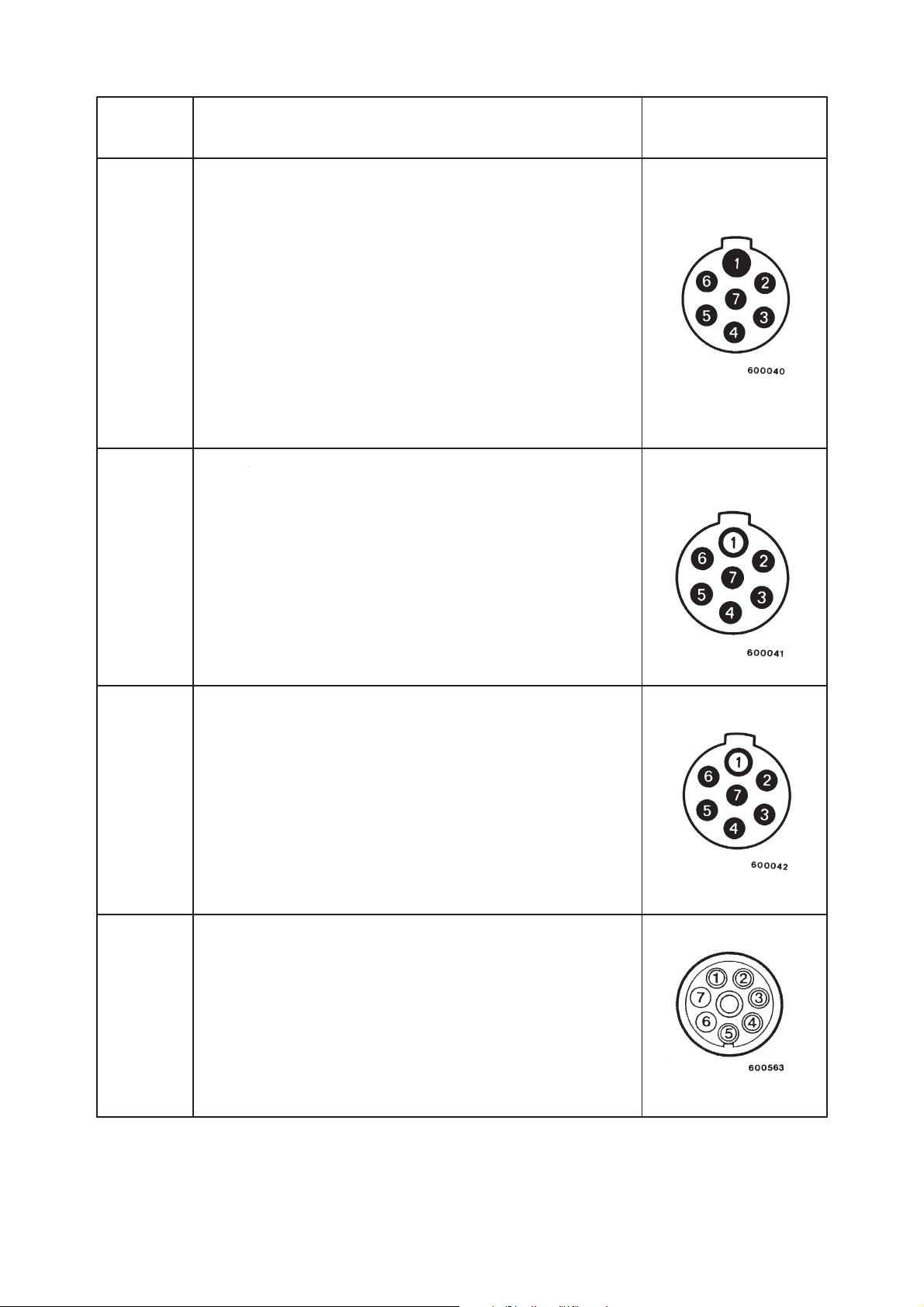
TENSION DESIGNATION ET NORME SCHEMA DU SOCLE
(vue de face)
24 Volts Socle type 24 S
(Norme – BNA.R.43.409 d’Avril 1982
– ISO 3731)
C’est un socle supplémentaire qui se monte en plus du
socle 24 N.
1 – Masse
2 – Sans affectation
3 – Feux de recul
4 – Alimentation “+”
5 – Contrôle par mise à la masse
6 – Alimentation “+” supplémentaire
7 – Feu arrière de brouillard
24 Volts Socle 24 P (Pétrolier)
(Norme – BNA.R.10.120 de Juin 1977)
Socle pour véhicules TMD–ADR se monte en
plus du socle 24N.
1 – Masse
2 – Eclairage des vannes
3 – Feux de recul
4 – Alimentation “+”
5 – Masse isolée
6 – Sans affectation
7 – Feu arrière de brouillard
24 Volts Prise ABS spécifique
(Norme ISO 7638)
1 – Alimentation puissance (30A)
2 – Alimentation commande (2A)
3 – Masse commande (2A)
4 – Masse puissance (30A)
5 – Information (2A)
6 – Libre
7 – Libre
24 Volts Socle type 24 N
(Norme – BNA R 43 406 de janvier 1976
– ISO 1185)
1 – Masse
2 – Feux de position arrière et encombrement gauche
et éclairage plaque d’immatriculation
3 – Feux indicateurs de direction gauche
4 – Feux de stop remorque
5 – Feux indicateurs de direction droit
6 – Feux de position arrière et encombrement droit
et éclairage plaque d’immatriculation
7 – Disponible
La broche 7 est prévue dans certains pays pour le contrôle
frein de remorque.
RENAULT V .I. 06/01 A18 DT 1/370
24 N type socket
(Standard: — BNA.R43.406 dated January 1976
— ISO 1185).
1 — Earth.
2 — LH rear side and marker lamp and number plate illumi-
nation lamp.
3 — LH direction indicator lamps.
4 — Stop lamps.
5 — RH direction indicator lamps.
6 — rear side and marker lamps and number plate illumina-
tion lamp.
7 — Trailer braking lamp.
Ter minal 7 is scheduled in certain countries for supplying
power to regulation trailer brakes. Under no circumstances
must it be used as an earth terminal.
24 S type socket
(Standard: — BNA.R43.409 dated April 1982
— ISO 3731).
This is a supplementary socket which is assembled in
addition to the 24 N socket.
1 — Earth.
2 — Not allocated.
3 — Reversing lamp.
4 — Power supply.
5 — Earthing monitor.
6 — Supplementary power supply.
7 — Rear fog lamp.
24 P (oil tanker) type socket
(Standard: — BNA.R.10.120 dated June 1977)
This is the socket for ADR (Transport of Hazardous
Substances) vehicles which is assembled in addition to the
24 N socket.
1 — Earth.
2 — Valve lighting.
3 — Reversing lamp.
4 — Positive (+) power supply.
5 — Insulated earth.
6 — Not allocated.
7 — Rear fog lamp.
ABS specific type socket
(Standard: — ISO 7638)
1 — Power (30A).
2 — Control power supply (2A).
3 — Control earth (2A).
4 — Power ear th (30A).
5 — Information (2A).
6 — Free.
7 — Free.
SUPPLY
VOLTAGE
DESCRIPTION AND STANDARDS SOCKET DIAGRAM
(front view)

La prise 15 voies peut être montée sur un véhicule équipé de prises 24N et 24P en utilisant un adaptateur
24N/24P – 15 voies réf. : 50 01 851 060 disponible au département pièces de rechange Renault V.I.
1.15.7 Feux indicateurs de direction supplémentaires
– Sur tracteurs ou camions
Dans le cas où les feux prévus ne remplissent pas entièrement les conditions de la réglementation, le carrossier
doit rajouter des feux supplémentaires alimentés par le même circuit que le feu avant ou par un circuit spécial
si la centrale en est munie. Respecter la puissance admissible.
Le montage de tout autre feu non exigé par les impératifs de la réglementation est interdit.
– Sur remorque et semi-remorque
Les normes actuelles concernant les prises de remorque ne prévoient que deux circuits pour les clignotants,
un pour le côté droit et un pour le côté gauche. Le montage de feux supplémentaires sur remorque ou semi–re-
morque est interdit à partir des feux contrôlés remorque.
L’addition de feux supplémentaires nécessite la mise en place de nouvelles lignes tirées des feux non-
contrôlés de la centrale.
Surcharge
Le montage de feux supplémentaires au-delà de la puissance indiquée sur la centrale est formellement
interdit ; cette surcharge a pour conséquence notamment (suivant les cas) :
– de réduire notablement la durée de vie de la centrale, même si le fonctionnement paraît normal,
– de perturber le fonctionnement de la centrale clignotante (les feux restent allumés sans clignoter),
– de mettre l’appareil hors circuit tant que dure la surcharge.
Protection de la centrale clignotante (selon équipement du véhicule)
En cas de surintensité, la centrale ne fonctionne plus. Pour la remise en service :
– ramenez la commande des feux clignotants à la position 0,
– recherchez et supprimez la cause de surintensité (lignes ou feux).
Vous pourrez alors réutiliser les feux clignotants normalement.
TENSION DESIGNATION ET NORME SCHEMA DU SOCLE
(vue de face)
24 Volts Socle type 24 N
(Norme – ADR 1999 IP54 et anti–décrochement
– ISO 12098)
1 – Feux indicateurs de direction gauche
2 – Feux indicateurs de direction droit
3 – Feu arrière de brouillard
4 – Masse
5 – Feux de position arrière et encombrement gauche et
éclairage plaque de police
6 – Feux de position arrière et encombrement droit
et éclairage plaque d’immatriculation
7 – Feux de stop
8 – Feux de recul
9 – Alimentation “+” 24 V
La prise 15 voies remplace depuis juillet 1999 les prises
24N et 24P.
Les voies 10, 11, 12, 13, 14, 15 ne sont pas affectées.
DT 1/370 A19 RENA UL T V.I. 06/01
15-pin trailer socket
(Standard: — ADR 1999 IP54 and anti-unhooking
— ISO 12098).
1 — LH direction indicator lamps
2 — RH direction indicator lamps
3 — Rear fog lamp
4 — Earth
5 — RH rear side/parking and marker and registration plate
lamps
6 — LH rear side/parking and marker and registration plate
lamps
7 — Stop lamps
8 — Reversing lamps
9 — 24V positive (+) power supply
Since July 1999, the 15-way socket replaces 24N and 24P
sockets.
Channels 10, 11, 12, 13, 14, 15 are unaffected.
The 15-way socket can be mounted on vehicles equipped with 24N and 24P sockets with the use of a 15-way
24N/24P adapter ref. N° 50 01 851 060 available from the RENAULT V.I. Spare Parts department.
1.15.7 Additional direction indicator lamps
— On tractors and rigids
Should the lamps provided not meet all the requirements of the legislation in force, the bodybuilder may add
extra lamps supplied with power by the same circuit as the front lamp or by a special circuit should one be
available from the flasher unit.In all cases, comply with the power rating.
We strongly advise you to refrain from fitting any other lamp not required by the regulations.
— On trailers and semi-trailers
The standards in force concerning trailers require only two circuits for the flasher units:one circuit for the RH
side and the other for the LH side. No additional lamps must be fitted on the trailer or semi-trailer which run
from the monitored trailer lamps.
The addition of extra lamps entails the fitting of new wire runs which have to be drawn from the non-
monitored lamp terminals in the flasher unit.
Overloading
Under no circumstances must extra lamps be fitted that exceed the power rating on the flasher unit.The main
consequences of such overloading are as follows:
— The service life of the flasher unit is shortened, even when it would appear to be operating nor mally in spite
of the overload.
— Operation is adversely affected by intermittent or permanent sticking of the contacts (the lamps remain lit
without flashing)
— The appliance may be off-circuit for the duration of the overload.
Protection of the flasher unit (depending on the vehicle equipment)
In the event of excess current, the flasher unit will cease to operate.To retur n it to ser vice:
— Move the flashing lights control switch to the 0 “off” position.
— Find the cause of the overcurrent (lines or lamps) and remedy it.
You will then be able to use the flashing lights again normally.
SUPPLY
VOLTAGE
DESCRIPTION AND STANDARDS SOCKET DIAGRAM
(front view)
1.16 Equipement pneumatique
L’adjonction d’une servitude supplémentaire non prévue par le constructeur doit se raccorder impérativement
au circuit spécifique servitudes.
La consommation en air comprimé de cette servitude ne doit en aucun cas compromettre le temps de remplis-
sage des circuits de freinage imposé par la législation en vigueur.
Les services technico-commerciaux RENAUL T V.I. sont à votre disposition pour tous renseignements complé—
mentaires.
1.16.1 Réglementation
Il est interdit de modifier le circuit de freinage qui est homologué et conforme aux normes prescrites par le code
de la route.
Toute modification sans accord préalable de RENAULT V.I. engage la seule responsabilité du réalisateur.
1.16.2 Tubes polyamide
Repérage
Avant toute intervention de dépose d’appareils ou de débranchement de canalisations polyamide, repérer le tube
par rapport à l’orifice de raccordement sur l’appareil.
Codification utilisée sur les tubes polyamide (norme RENAULT V.I.).
Les tubes polyamide sont repérés par un code couleur matérialisé par du ruban adhésif ou par des anneaux
élastiques.
Code freinage :
RENAULT V .I. 06/01 A20 DT 1/370
1.16 Air-operated equipment
Should it be necessary to add auxiliary equipment not provided by the manufacturer, it must compulsorily be
connected to the circuit specifically provided for auxiliary equipment on the vehicle.
The compressed air consumption of such auxiliary equipment should under no circumstances compromise
the filling times of the brake circuits laid down by the legislation in force.
The RENAULT V.I. Product Applications Depar tment is at your disposal for any further information you may
require.
1.16.1 Regulations
It is forbidden to modify officially approved braking circuits which conform with the standards set out by the
Highway Code.
Any modification, without prior agreement from RENAULT V.I., is done under the sole responsibility of the
author of such a modification.
1.16.2 Polyamide pipes
Identification marking
Before removing any equipment or disconnecting polyamide pipes, mark the pipe in relation to the connec-
tion port on the equipment.
Coding system used on polyamide pipes (RENAULT V.I. standard):
Polyamide pipes are identified with a colour code marked with adhesive tape or by elastic rings.
Brakes code:
Constant
pressure
Delivered pressure
Sub-functions
Signalling pressure
Main functions
Front service brake Orange Orange — White Orange — Yellow
Rear service brake Blue Blue — White Blue — Yellow
Parking brake Green Green — White Green — Yellow
Trailer brake Red Red — White Red — Yellow
Extra brake Yellow Yellow — White Yellow — Yellow
DT 1/370 A21 RENA UL T V.I. 06/01
Coding used on pneumatic appliances (DIN standard)
0 — Air intake 5 — Free
1 — Pressurized supply 6 — Free
2 — Delivered pressure 7 — Antifreeze
3 — Air vent 8 — LubricatIon. 81 — Inlet. 82 — Outlet
4 — Signalling pressure 9 — Water cooling. 91 — Inlet. 92 — Outlet
When the figure is followed by a second figure, the latter figure indicates the sequence number.
Example: 41, 42, 43: The figure 4 indicates the signalling function, the figures 1, 2, 3 indicate a sequence
number in that function.
Replacement of a brake line
The entire length of a damaged polyamide pipe should be replaced by a pipe with identical characteristics
(length and diameter), and corresponding with the standard in force.(See technical memo 8655 group 53000,
part N° 50 20 034 156 available with spare parts).It must also be provided with coloured rings which are iden-
tical to those of the tube replaced.
Use an original manufacturer’s pipe available from the RENAULT V.I. Spare Parts warehouse.
The routing of a polyamide pipe must be carefully executed. Ensure there is no interference with sharp-edged
metal parts and there is no routing close to high temperature units. The pipes must be held at regular inter-
vals by plasticized clamps or run in existing ducting. Non-plasticized attachment clamps are absolutely for-
bidden.Take care to ensure the minimum radius of curvature of polyamide pipes is observed.
Modification to the length of the chassis
Modification to brake pipe lengths requires braking response times to be checked out, in accordance with the
legislation in force, and with agreement from the Type Approvals Department.
Connections for ratchet type pneumatic brake pipes type “RILAX 2000”
For the fitting of this type of connector, refer to and comply absolutely with the technical instruction sheet NT
8852 (method and tooling) available from the RENAULT V.I. Spare Parts Depar tment.
Dimension
Radius of curvature

RENAULT V .I. 06/01 A22 DT 1/370
2. GENERAL RULES TO BE OBSERVED WHEN FITTING BODYWORK
Before carrying out any work, protect the cab with a cover.
Our vehicles are equipped with plates, U-bolts or brac kets. Preparation work may involve extra drilling or wel-
ding.
The principles described below must be adhered to.
2.1 General principles of welding
2.1.1 Precautions
Protection of the batteries
A battery at the end of its charge produces a mixture of oxygen and hydrogen gas.The ignition of this gas
presents dangers of battery explosion in the case of the presence of a source of heat nearby. As a result,
during a welding operation near the batteries (i.e. engine compartment, front end of the vehicle), take out the
batteries and store them in a well-aired location away from the place where welding is being done. This
recommendation applies equally for grinding operations.
Soundproofing screens
In the case of welding or use of a disk sander, either provide effective protection or remove the soundproo-
fing screens, if necessary.
Protection of electrical and mechanical components
The vehicle is equipped with numerous electronic circuits: alternator, regulator, flasher units, speed limiter,
ABS, etc.
Before any operation in v olving electric arc welding, make an earth connection by disconnecting the two nega-
tive (-) and positive (+) cables from the batter y (starting with the earth cable) and connecting them to the
frame earth. If the vehicle is equipped with a master switch, this should kept engaged (circuit closed). Place
the earthing clamp as near as possible to the point of welding, but never on rotating parts (prop shaft, fan
hub, etc.) or on a subassembly having moving parts (i.e. air compressor, turbocharger, etc.)
Nearby plastic pipes and electrical cables, springs and air-suspension bags are to be protected or removed.
This also applies when grinding or drilling.
When reconnecting the battery, obser ve the polarities, commencing with the positive (+) terminal. Reversal
of polarity may cause irreparable damage to electronic components.
2.1.2 Preparation of parts for welding
Clean the parts, primarily at the location of the weld and at the connection of the ear thing wire. This allows:
— free and regular electrical current flow (regularity of weld bead),
— avoidance of inclusion of impurities in the molten metal (weld quality),
— avoidance of spatter and emission of smoke (safety for the welder).
For conversions (extensions, reductions and reinforcement gussets), we recommend arc welding with elec-
trode type B.When semi-automatic welding is use, the bodybuilder must be able to guarantee weld quality.

Préparation des bords spécifiques aux cadres–châssis
A – Avec soudure à arc électrique
B – Avec soudure sous protection gazeuse (MIG – MAG)
Méthode de soudage spécifique aux cadres–châssis
– préparation des bords à 45°
– pointage
– mise en place des abouts
– soudure d’un seul côté
– soudure du deuxième côté
– meulage des deux côtés
Abouts de cratère terminal
Les abouts ont pour but d’éviter une amorce de rupture aux extrémités du joint de soudure.
Positionner impérativement avant soudure des abouts (1) de même épaisseur que les tôles à assembler mainte-
nus par des dispositifs de serrage rapide.
Ils ne doivent être en aucun cas maintenus par des points de soudure sur les éléments à assembler.
DT 1/370 A23 RENA UL T V.I. 06/01
Preparation of specific edges on chassis frames
A — With electric arc welding
B — With weld under gas shield (MAG or MIG)
Method of welding to be specifically used on chassis frames
– Preparation of the edges at 45°
– Tack
– Position slave butts
– Weld on one single side
– Weld on second side
– Welds ground flush on both sides
Slave butts
The object of slave butts is to avoid the starting of cracks at the outside edges of the weld joint. Before final
welding align butts with plates of the same thickness as the plates to be joined, holding them in position using
quick action clamping devices.
They must not under any circumstances be held in position by weld tacks on the plates to be joined.

2.1.3 Procédés de soudure
Poste de soudure ARC statique ou rotatif
– poste de soudage à courant continu conseillé.
– baguettes enrobées.
Tableau d’utilisation des baguettes de soudure
Diamètre des électrodes (en mm)
2,5 3,15 (*) 4 (*) 5
Intensité (en ampères) 75 à 90 95 à 110 120 à 140 150 à 175
(*) Diamètres les plus fréquemment utilisés.
Electrodes enrobées conseillées : Norme NF EN 499 (Janvier 1995)
EN 499 E 38 2 1 NI B pour classe A – B – C
EN 499 E 46 2 1 NI B pour classe D – E
EN 499 E 50 2 1 NI B pour classe F
E 515/5 B 26 BH pour aciers classe F
Si mixage des aciers, prendre la catégorie d’électrode de l’acier le plus performant.
La norme NF EN 499 remplace la norme NF A 81–309.
Normes correspondantes
AFNOR
A 81.309
(12.1975)
ISO 2560
ASME (SFA 5.1)
AWS (AS.1.69)
DIN 1913 BS 639
E 435/4 B 26 BH E 435 B 26 (H) E 7016 E 453/4 B 10 E 435 B 26 (H)
E 515/5 B 26 BH E 515 B 26 (H) E 7018 E 515/5 B 10 E 515/6 B 26 (H)
Poste semi–auto MIG ou MAG
MIG : – Métal Inerte Gaz
– soudage avec fil électrode sous protection de gaz inerte (argon, hélium…)
– utilisé pour le soudage des aciers inoxydables et métaux non ferreux.
MAG : – Métal Active Gaz
– soudage avec fil électrode sous protection de gaz actif (CO
2,
argon + CO
2,
argon + CO
2
+ O
2)
– utilisé pour le soudage des aciers doux.
Diamètre du fil (en mm) Epaisseur à souder (en mm)
0, 8 Jusqu’à 2 mm
1, 0 de 2 à 8 mm
RENAULT V .I. 06/01 A24 DT 1/370
2.1.3 Welding process
Static or rotary arc welding set
— dc welding set recommended
— coated welding rods
Welding rod usage table
(*) Most frequently used diameters
Coated welding rods recommended: standard NF EN 499 (January 1995)
EN 499 E 38 2 1 NI B for class: A — B — C
EN 499 E 46 2 1 NI B for class: D — E
EN 499 E 50 2 1 NI B for class: F
E 515/5 B 26 BH for steels class F
If steels are mixed, take the best performing steel electrode categor y.
Standard NF EN 499 replaces standard NF A 81-309.
Relevant standards
MIG or MAG semi-automatic welding set
MIG: — Metal Inert Gas
— for welding with electrode wire under inert gas shield (Argon, Helium…)
MAG: — Metal Active Gas
— for welding with electrode wire under active gas shield (CO
2
, Argon + CO
2
, Argon + CO
2
+ O
2
).
— used for welding mild steels.
Electrode diameter (in mm)
Average current (in amperes)
Wire diameter (in mm) Thickness to be welded (in mm)
2.5
3.15
75 to 90
95 to 110
120 to 140
150 to 175
0.8
up to 2 mm
from to 8 mm
1.0

2.1.4 Correspondance des aciers
Les quatre classes concernent les produits plats laminés à chaud en acier à haute limite d’élasticité pour formage
à froid, définis aujourd’hui dans la norme française et européenne NF EN 10149–2 qui a remplacé la norme NF
A 36.231.
Cahier des charges RENAULT V.I. 31.09–402
KCV à — 20°C
J/cm
2
sens long mini
= correspondance
européenne NFEN 10149–2
Normes françaises
= correspondance
DIN
Normes allemandes
= correspondance
BS
Normes britanniques
= correspondance
ASTM
Normes américaines
= correspondance
Normes EURONORM
149-80
DT 1/370 A25 RENA UL T V.I. 06/01
UTS in N/mm
2
min.
YP at 0.2% in
N/mm
2
min.
E % min.
KCV at — 20°C
J/cm
2
min., longitudinal
Bending, transversal
Grain size
= European
equivalent
French standards
= German standards
equivalent
DIN
= British standards
equivalent
BS
= American standards
equivalent
ASTM
= EURONORM
standards equivalent
149-80
2.1.4 Equivalent steel grades
The four classes relate to hot rolled steel plate with a high yield strength for cold forming, as currently set out
in the French and European Standard NF EN 10149-2, which has replaced French Standard NF A 36.231.
High yield strength sheet steel (dispersed carbon)
RENAULT V .I. Specification 31.09-402
Class C Class D Class E Class F
1.5
Fe
1.5

A : Déport du renfort par rapport à la face extérieure du longeron
B : Déport du renfort par rapport au bord du longeron
e : Epaisseur du longeron
1 : Soudures par trous ou boutonnières à souder en quinconce
Epaisseur du longeron A B
e t 6 mm 10 mm 15 mm
e w 6 mm 15 mm 15 mm
RENAULT V .I. 06/01 A26 DT 1/370
2.2 Reinforcement, extension, reduction of sidemembers
2.2.1 Bans
It is absolutely forbidden to weld onto sidemembers, except for reinforcement, extension, reduction, and the
following instructions must be observed:
— Do not weld on the edges of flanges.
— Do not weld in sidemember bending radii.
— In the case of flat irons: no directly opposing welds on the two faces of the same web — only “alternate” or
“plug” welds are authorized.
— No welds which are less than 15 mm from the edge of a hole.
Insofar as possible, we advise you to have modifications of the lengths of sidemembers carried out by spe-
cialists.
— The general rules for welding in the paragraph entitled “General Principles of Welding” must be strictly fol-
lowed.
Only conversions (extensions or reductions) rendering the modified vehicle completely in conformity with a
type approved chassis are permitted without additional testing, with certification from the vehicle manufactu-
rer.
2.2.2 Reinforcement of sidemembers
— For inner reinforcements and chassis flange stiffeners, the thickness should be the same as the thickness
of the sidemember.
NOTE
The steel grade must be identical to that used for the sidemember.
Examples of reinforcements
Sidemember upper and lower stiffeners
A: Offset of the stiffener in relation to the external face of the sidemember
B: Offset of the stiffener in relation to the edge of the sidemember
e:Thickness of the sidemember
1: Welds through round or slotted holes, staggered
Thickness of the sidemember

Renforts supérieurs et inférieurs par cornière :
Modes de liaison
Dans le cas de renforts constitués de plats (sur l’aile supérieure ou sous l’aile inférieure des longerons) nous
préconisons la fixation par :
Cordons intermittents de soudure électrique : à titre indicatif, cordons de 80 mm espacés de 120 mm et dispo—
sés en quinconce.
Soudures “BOUCHON’’ : à titre Indicatif, trous de diamètre 14 à 18 mm ou boutonnières (1) diamètre 14 x 50
mm à 18 x 5 0 mm “au pas’’ de 200 mm mini à 300 mm maxi, disposées en quinconce, avec soudure de bonne
qualité.
ATTENTION
Pas de soudure verticale sur l’âme des longerons, pas de soudure transversale sur les ailes des longerons.
DT 1/370 A27 RENA UL T V.I. 06/01
Upper and lower stiffeners using angle-irons :
Method of joining
In the case of stiffeners made from flats (on the upper flange or under the lower flange of sidemembers), we
recommend attachment by:
Intermittent beads by electric welding: as guidance, 80 mm beads spaced 120 mm apart and staggered.
“PLUG” welds: as guidance, round holes diameter 14 to 18 mm or slotted (1) holes diameter 14 x 50 mm to
18 x 50 mm at a “pitch” of 200 mm min. to 300 mm. max., staggered, with good quality weld.
WARNING
No vertical welds on sidemember webs. No transversal welds on sidemember flanges.

Longeron avec plat de renfort sur l’aile
RENAULT V .I. 06/01 A28 DT 1/370
Extension, shortening of sidemembers in the wheelbase
Key
A – piece of sidemember added,
B – sidemember,
C – reconstituted stiffener,
D – welds projecting beyond flanged edge with butt-ends then longitudinal grinding (elimination of sharp
edges),
e – thickness of the sidemember,
F – angle-iron of thickness (E) max.: E ≤ (e — 1 mm),
h – height of the sidemember,
J – weld penetration clearance (about 2 mm),
L – max. length of extension,
X – max. length of projection of the stiffener measured on the edge of the flange (extension),
Y – min. length of support of the stiffener measured on the edge of the flange of the sidemember (extension),
Z – min. length of support of the stiffener measured on the edge of the flange (stiffener without extension).
Extension of the sidemembers in the wheelbase
Sidemember without stiffener flat on the flange
Sidemember with stiffener flat on the flange

Raccourcissement des longerons dans l’empattement
DT 1/370 A29 RENA UL T V.I. 06/01
2.2.3 Modification of the rear overhang
If the bodywork or the equipment fitted do not alter the weight and dimensional characteristics of the chassis
entered on the description sheet, the vehicle can be submitted to the Type Approval Department without any
action being necessary on the par t of RENAULT V.I. (within the permitted limits in force).
— W elding stiffeners are required for drawbar rigids or if the extension is longer than 400 mm for a solo vehicle.
Examples: Drawbar rigid; tail lift; crane at the rear of the chassis; tipper; etc.
— Extension of the rear overhang will also be required when the rear extremities of the bodywork project
beyond the maximum authorized value which is indicated on the bodybuilder’s drawing and calculation
sheets relating to the vehicle.
Attachment of crossmembers
Crossmembers should be attached with nut and bolt hardware of the 10.9 S2S protected class as per stan-
dard 01714002 and distributed by RENAULT V.I.
Towing crossmembers
Please refer to the chapter on “Drawbar crossmembers” in the section entitled “SPECIFIC FEATURES OF
THE MIDLUM VEHICLE”.
Intermediate crossmembers
In the case of extension of the wheelbase or the rear ov erhang, it is essential to add crossmembers , so as not
to weaken the rigidity of the frame.
Observe the following instructions:
— Between two crossmembers, the spacing must be no greater than the original spacing.
— If the extension to the overhang is longer than 500 mm, the rear crossmember must be moved and an inter-
mediate crossmember fitted which is identical to the others.
Shortening of sidemembers in the wheelbase

RENAULT V .I. 06/01 A30 DT 1/370
2.3 Attachment of bodywork
The bodywork must be correctly attached so that both the static and dynamic stresses are freely transmitted
without causing excessive local strain, which could prejudice the reliability of the chassis frame or affect the
road behaviour of the vehicle.
The following rules apply to the fastening of various standard bodies fitted to our chassis cabs, such as plat-
forms, vans, tippers, and tankers. For special cases, contact the Product Applications Department.
For body design (i.e.length, load distribution, location of accessories on sidemembers, etc.) refer to the CD-
ROM “Information for Bodybuilders” or the 1:20 scale bodywork drawing which we supply upon simple
request.
Fastenings should always be tightened progressively and alternately.
The shape of sub-frames or underbodies should always be tapered towards the front (i.e. at the back of the
cab), so as to avoid sudden variations in iner tia (refer to chapter entitled “Finishing of sub-frame behind the
cab”.
2.3.1 Bans
— The use, drilling or welding of spring hangers.
— Any modification of: the chassis, the driveline, or the suspension.
— Fastening of sub-frames to our sidemembers by welding.
— The drilling of stiffener gussets.
— The notching of sidemembers, gussets or crossmembers.
— With the exception of special cases described in this document, the use or modification of our nut and bolt
hardware and our riveting for the attachment of a body or sub-frame.
— The attachment of sub-frames by hooks (use U-bolts).
All bodies attached by clamps and brackets must mandatorily have 1 inertia stop to the aft of each side-
member to stop the body from moving in the event of fierce braking, as well as 4 body guides 2 at the front,
2 at the rear).
For bolted fastenings, comply with the following instructions:
— By preference use brackets attached to the chassis.
— Use the fixing bolt holes 11, 13 or 15 mm diameter depending on the particular vehicle, spread out along
the length of the sidemembers of the chassis frame.
— Take good note of the attachment principles, set out in the chapter on the “Attachment of sub-frames”.
2.3.2 Protection against exhaust heat radiation
Depending on the features of your bodywork or equipment, the fitting of a heat shield on the original protec-
tion is recommended.

Nous proposons également, lorsque le faux-châssis est constitué par du tube carré ou rectangulaire, la coupe
ci-dessous.
A : plaque d’obturation d’épaisseur 1,5 mm
DT 1/370 A31 RENA UL T V.I. 06/01
2.4 Sub-frame
In order to attach bodywork to the frame of the chassis, you should allow for the fitting of a sub-frame whose
module of inertia (I/V) is determined in accordance with the vehicle series in question (refer to the section
entitled “MIDLUM special bodybuilding features”.
In order to ensure better distribution of the stresses along the sidemembers, you must allow for a cut-out as
far forward as possible under the cab.
2.4.1 Finishing of sub-frames behind the cab
When the sub-frame is constructed of square or rectangular tube section, we also suggest the cut-out shown
below.
A: Blank off with 1.5 mm thick sheet metal

2. 5 Visserie et couples de serrage pour pièces en acier et en fonte
Les couples indiqués dans le tableau sont des couples nominaux (valeur moyenne calculée à partir du couple
minimal et du couple maximal).
La classe III est la classe de précision de serrage (± 20 % du couple nominal) suivant la norme 01504002
(coefficient de frottement 0,15 ± 0,03).
Les couples de serrage sont donnés pour une visserie sèche et traitée dacromet.
Désignation
Caractéristique Classe acier Réf. P.R. Couple de serrage
Vis
Vis à embase
H 10 x 125 L 30
H 10 x 125 L 50
H 12 x 125 L 40
H 12 x 125 L 45
H 12 x 125 L 50
H 12 x 125 L 60
H 14 x 150 x 40
H 14 x 150 x 50
H 14 x 150 x 60
H 14 x 150 x 90
H 14 x 150 x 100
H 14 x 150 x 110
H14 x 150 x 120
H14 x 150 x 130
H14 x 150 x 140
H 16 x 150 x 50
H 10 x 125 L 30
H 12 x 125 L 40
10.9
10.9
10.9
10.9
10.9
10.9
10.9
10.9
10.9
10.9
10.9
10.9
10.9
10.9
10.9
10.9
10.9
10.9
50 03 101 460
50 03 101 148
50 03 101 151
50 03 101 749
77 03 101 679
50 03 101 153
50 03 101 161
50 03 101 162
50 03 101 163
50 03 101 169
50 03 101 660
50 03 101 171
50 03 101 172
50 03 101 887
50 03 101 173
50 03 101 103
50 03 002 048
50 03 002 049
60 N.m
60 N.m
110 N.m
110 N.m
110 N.m
110 N.m
170 N.m
170 N.m
170 N.m
170 N.m
170 N.m
170 N.m
170 N.m
170 N.m
170 N.m
220 N.m
60 N.m
110 N.m
Désignation Caractéristique Réf.P.R.
Rondelle conique
Rondelle plate
Rondelle conique BELLEVILLE
10 x 20 x 2,2
10 x 24 x 2,8
10 x 27 x 2,8
12 x 30 x 3, 2
14 x 28 x 3
16 x 32 x 3,4
16 x 39 x 3,6
10 x 22 x 3
10 x 27 x 3
10 x 24 x 2,5
12 x 28 x 5
12 x 32 x 2,5
14 x 30 x 5
14,5 x 35 x 1,8
50 03 058 081
50 03 058 071
50 03 058 076
50 03 058 075
50 03 058 069
50 03 058 034
50 03 058 070
50 03 053 453
50 03 053 455
50 03 053 026
50 10 054 526
50 03 053 441
50 03 053 014
00 21 721 040
Désignation Caractéristique Classe acier Réf. P.R . Couples de serrage
Ecrou
Ecrou frein DRH
(à embase)
10 x 125
12 x 125
14 x 150
16 x 150
10 x 125
12 x 125
14 x 150
10
10
10
10
10
10
10
50 03 032 156
50 03 032 157
50 03 032 159
50 03 032 236
50 03 034 246
50 03 034 248
50 03 034 250
60 N.m
110 N.m
170 N.m
220 N.m
60 N.m
110 N.m
170 N.m
RENAULT V .I. 06/01 A32 DT 1/370
2.5 Nuts and bolts, tightening torques for parts in steel and cast iron
The torques indicated in the table are the nominal torques (i.e. average value calculated on the basis of the
minimum and maximum torque).
Class III is the class covering precision tightening (± 20 % of nominal torque) in accordance with Standard
01504002 (coefficient of friction 0.15 ± 003).
The tightening torques are given for nut and bolt hardware that is dry and coated with Dacromet.
Description Characteristics Class of Steel Part Nos.
Part Nos.
Tightening torque
Description
Description
Characteristics
Characteristics
Class of Steel Part Nos. Tightening torque
Cone washer
Flat washer
Cone washer “BELLEVILLE”
type
Nut
Locknut DRH
(flanged)
Screw
Collar screw
2.6
2.8
2.8
3.2
3
3.4
3.6
3
3
2.5
5
2.5
5
1.8
14.5

2.6 Adjonction d’équipement sur carrosserie
La fixation d’équipements sur carrosserie est à réaliser avec des écrous à sertir étanches.
Outillage et écrous à sertir
Ecrou à sertir M6 – fût hexagonal
Réf. : 50 03 043 050
Méthode :
– Percer au Ø 9,2 (voir chapitre “Perçage éléments de carrosserie pour montage d’accessoires”).
– Utiliser l’outillage OPEX de OTALU SA (N° Agrément Renault V.I. 9824).
– Réaliser le poinçonnage hexagonal.
– Poser l’écrou à sertir.
Indications :
– Couple de serrage maxi 10 Nm
– Longueur du fût dépassant sous support après sertissage : 17 mm.
Ecrou à sertir M8 – fût hexagonal
Réf. : 50 30 043 052
Méthode :
– Percer au Ø 11,2 (voir chapitre “Perçage éléments de carrosserie pour montage d’accessoires”).
– Utiliser l’outillage OPEX de OTALU SA.
– Réaliser le poinçonnage hexagonal.
– Poser l’écrou à sertir.
Indications :
– Couple de serrage maxi 24 Nm
– Longueur du fût dépassant sous support après sertissage : 21 mm
DT 1/370 A33 RENA UL T V.I. 06/01
2.6 Addition of equipment to the bodywork
The attachment of equipment to the bodywork must be done with fluidtight crimping nuts.
Tooling and crimping nuts
Method:
— Drill a 9.2 mm diameter hole (refer to chapter entitled “Drilling of bodywork members for the fitting of acces-
sories”).
— Use the OPEX tooling from OTALU S.A.
— Punch out the hexagonal.
— Insert the nut for crimping.
Information:
— Tightening torque max.10 Nm.
— Length of barrel projecting under bracket after crimping: 17 mm.
Method:
— Drill a 11.2 mm diameter hole (refer to chapter entitled “Drilling of bodywork members for the fitting of acces-
sories”).
— Use the OPEX tooling from OTALU S.A.
— Punch out the hexagonal.
— Insert the nut for crimping.
Information:
— Tightening torque max.24 Nm.
— Length of barrel projecting under bracket after crimping: 21 mm.
M8 crimp nut — hexagonal barrel
Part N °: 50 03 043 052
M6 crimp nut — hexagonal barrel
Part N °: 50 03 043 050

RENAULT V .I. 06/01 A34 DT 1/370
2.7 Rear run-under guard
RENAULT V.I. obtains approval for its equipment to cover the requirements of its range. Their attachment
being by means of bolts, this allows them to be moved down along the sidemembers to suit such modifica-
tions that the chassis may undergo. This must be observed, along with the maintenance of the attachment
method detailed on the 1:20 scale bodywork drawing and compliance with the dimensional requirements
under the regulations.
A vehicle which is not equipped at the time of delivery can be fitted afterwards, f ollo wing a conversion making
the fitting compulsory, using items which can be supplied from the Parts Stores of our dealers.
Changing of position of items of equipment
Modifications of a RENAULT V.I. vehicle for the fitting of bodywork and equipment requires technical appro-
val to be obtained from the Product Applications Department of RENAULT V.I.
3. SPECIFIC EQUIPMENT FEATURES
3.1 Running the engine when vehicle stationary
Under the conditions of running an engine for a long period under load, it is vital to fit an additional cooler unit
in order to keep the temperature of the engine at a normal level (water temperature approx. 80° C).
The prolonged use of the engine under these conditions can cause malfunctions which could adversely affect
the life of the engine.
3.2 Mounting of power take-offs and flanged pumps
RENAULT V.I. power take-offs (PTOs) and their adapter kits should be ordered from the RENAULT V.I. Spare
Parts Department. In order to carry out the fitting, refer to the specific information circulars that are available
from the Product Applications Department.
Bearing in mind the weight and the large overhang required for certain PTOs having flanged pumps, the rear
of these units should be supported by a suitable bracket attached to the rear of the gearbox.
Comply with the standard NF ISO 7653
IMPORTANT
It is compulsory at the time of fitting a power take-off to ensure that there is a certain amount of play in the
setting adjustment, so as to allow an ideal backlash of 0.15 to 0.25 mm then to fit a gasket or apply paste in
order to achieve a good seal and also to top-up the oil level. (Refer to the vehicle maintenance handbook).
Refer to our Product Information Sheet and 1:20 scale bodywork drawing on “power take-offs”, which can be
requested from our Product Applications Department.

3.3 Prise de mouvement avant (nez de vilebrequin)
Prédisposition de montage RENAULT V.I.
Dans le cas d’un entraînement par courroie, des poulies avec gorges supplémentaires peuvent exister en fonc—
tion des motorisations.
Consulter le service technico–commercial pour obtenir les informations correspondantes et un accord technique
de montage.
3.4 Prises de mouvement avant et arrière
3.4.1 Alignement des transmissions
Plusieurs critères minimum de base doivent être respectés simultanément pour réaliser un bon alignement des
transmissions.
Critères d’angularité (ou Angle b
E
équivalent admissible de toutes les articulations)
b
E
doit respecter la condition suivante :
Règle pour le signe b
On considère que la fourche 1 est la fourche de référence.
b > 0 lorsque les fourches menantes sont parallèles à la première fourche menante (Ma).
Exemple 1 :
b
E
+
|
b
a
2
) b
b
2
) b
c
2
– b
d
2
|
Ǹ
M – Fourches menantes
N – Fourches menées
b < 0 lorsque les fourches menantes sont perpendiculaires à la première fourche menante (Ma).
Exemple 2 :
b
E
+
|
b
a
2
) b
b
2
– b
c
2
) b
d
2
|
Ǹ
b
E+
|
b
a
2
« b
b
2
« b
c
2
«
Ǹ
…
|
b
E
v 3°
DT 1/370 A35 RENA UL T V.I. 06/01
3.3 Front power take-offs (crankshaft nose)
RENAULT V .I. pre-arrangement
For belt drive units, pulleys with extra grooves fitted to the engine may be available.
Consult the Product Applications Department to obtain the relevant information and technical approval for the
assembly.
3.4 Front and rear power take-offs
3.4.1 Propeller shaft alignment
In order to achieve satisfactory propeller shaft alignment, several minimum basic criteria have to be obser-
ved.
Angularity criteria (or: equivalent angle of inclination β
E
permissible for all articulations).
This angle β
E
must comply with the following condition:
Rule for sign β:
Yoke N° 1 is to be considered as the reference yoke.
ββ
> 0 when the leading yokes are parallel to the first leading yoke (Ma).
Example 1:
M — Leading yokes
N — Trailing yokes
ββ
< 0 when the leading yokes are perpendicular to the first leading yoke (Ma).
Example 2:

Critères d’accélération angulaire q
1
Critères calculés pour une vitesse de rotation maximale d’utilisation de l’arbre de transmission (N)
q
1
: critère d’accélération angulaire en rd/s
2
N : vitesse de rotation maximale en tr/min
NOTA
Cette valeur est calculée sans amplification dynamique des tubes de transmission et des paliers.
Critère mesuré q
2
:
La valeur Critère q
2
d’accélération angulaire ou de vibrations de torsion ne doit pas excéder 1500 rd/s
2
en sorti
prise de mouvement et en un quelconque point de la chaîne cinématique pour une inertie avale “I” telle que “
< 0,2 m
2
kg.
q
2
v 1500
rd
s
2
NOTA
Cette valeur limite q
2
tient compte d’une amplification dynamique éventuelle de la chaîne cinématique.
Critères des sollicitations transversales des tubes de transmission et des paliers
Exemple ba et bb maximum à ne pas dépasser.
– b
a
t2° pour une transmission à palier
– b
b
t7° pour une transmission coulissante
NOTA
Si cette valeur de 7° doit être dépassée pour des raisons d’encombrement, le constructeur du véhicule doit êt
consulté.
q
1
+
ǒ
b
E
p
180
Ǔ
2
ǒ
p N
30
Ǔ
2
q
1
v 270
RENAULT V .I. 06/01 A36 DT 1/370
Angular acceleration criteria
ΘΘ
1
Calculated criterion for a theoretical maximum speed of rotation (N).
NOTE
This value is calculated without dynamic amplification of the prop shaft tubes and bearings.
Measured criteria
ΘΘ
2:
The angular acceleration or torsional vibrations criteria value Θ2 must not exceed 1500 rd/s
2
at the PTO out-
put or at any point whatsoever of the driveline for a downstream inertia of I such that I ≤ 0.2 kg/m
2
.
NOTE
This limit value Θ2 takes into account possible dynamic amplification of the driveline.
Transversal stress criteria for prop shaft tubes and bearings.
Example β1 and β2 maximum not to be exceeded.
—
ββ
a < 2° for a prop shaft with bearing.
—
ββ
b < 7° for a prop shaft with sliding yoke.
NOTE
If this 7° value has to be exceeded for space or clearance reasons, the vehicle manufacturer must be consulted.
Θ1: criter ion of acceleration in rd/s
2
N: max. speed of rotation in rpm
O
O
O
O
O

3.4.2 Equilibrage des transmissions
Valeur du balourd admissible (B) :
B v 3
g cm
kg
par plan dȀéquilibrage
1 – demi–transmission
2 – transmission
NOTA
g = 10m/s
2
3.4.3 Calcul de la longueur maximale admissible d’une transmission en fonction d
son régime de rotation (L, L1 ou L2).
L : entraxe entre centres d’articulation d’une transmission
L1 : entraxe entre soudures d’articulation d’une demi–transmission
L2 : entraxe entre centres d’articulation d’une demi–transmission
L1 = L2
Nt : régime maximal d’utilisation de la transmission
1,2 : coefficient de sécurité
D : grand diamètre du tube de transmission
d : petit diamètre du tube de transmission
3.5 Chaîne cinématique du véhicule
T oute modification de la chaîne cinématique est interdite. Pour les cas particuliers, un accord technique doit êtr
demandé auprès du sevice technico–commercial RENAULT V.I.
Toute modification de transmission doit être réalisée en respectant les paragraphes 3.4.2 et 3.4.3.
L +
K
Nt 1, 2
Ǹ
K + 0,75 1, 22 10
5
D
2
) d
2Ǹ
avec
DT 1/370 A37 RENA UL T V.I. 06/01
3.4.2 Propeller shaft balancing
Permissible imbalance value (B):
1 — 1/2 prop shaft
2 — prop shaft
per balancing plane
NOTE
g = m = 10 m/s
2
3.4.3 Maximum permissible length of a prop shaft as a function of the rotating speed
(L, L1 or L2)
L: Distance between centres of ar ticulation of a prop shaft.
L2:Distance between centres of articulation welds of a half prop shaft.
L1: Distance between centres of ar ticulations of a half prop shaft.
L1 = L2
Nt = prop shaft maximum operating speed
1.2 = safety coefficient
D = prop shaft large diameter
d = prop shaft small diameter
3.5 Vehicle driveline (powertrain)
Any modification to the driveline is forbidden. For special cases, agreement must be obtained from the
RENAULT V.I. Product Applications Department.
Any propeller shaft modifications must only be carried out in conformity with the requirements of paragraphs
3.4.2 and 3.4.3.
with
1.22

RENAULT V .I. 06/01 A38 DT 1/370
3.6 Mounting of handling cranes
The installer of the crane is responsible with regard to compliance with the regulations, and also for the stabi-
lity of the vehicle. The recommendations of RENAULT V.I. are only concerned with the attachment of the
equipment.
3.6.1 Mounting on the sub-frame
The mounting of a crane on the chassis behind the cab or in the rear overhang requires the fitting of a speci-
fic sub-frame.
The sub-frame module is defined in the graph of inertia in accordance with the lifting torque only for a crane
mounted behind the cab and on rigid or drawbar rigid vehicles (refer to the next page).
For all mountings of cranes in the rear overhang, off-limits and on tractors, consult the RENAULT V.I. Product
Applications Department.
The sub-frame must be in one single piece, starting from the rear of the cab, and extending as far back as the
rear tip of the overhang.The front end must be finished in a single or double bevel (refer to the chapter 2.4.1
entitled “Finishing of the sub-frame behind the cab”).
Should the crane be mounted in conjunction with another item of mobile equipment, one single sub-frame shall
be designed in accordance with that item of equipment which places the most strain on the sidemembers.

3.6.2 Abaque de l’inertie du faux–châssis en fonction du couple de levage
Exemple :
Un châssis avec longerons de 252 mm, équipé d’une grue d’une capacité de levage de 10 tonnes /mètre.
Il nécessite donc un faux-châssis construit en UPN de 160 (— sens de lecture).
L’UPN peut être remplacé par tout autre profilé donnant une inertie totale équivalente.
PORTEUR – PORTEURS-REMORQUEURS SANS FAUX-CHÂSSIS
HORS LIMITES
COUPLE LEV AGE de la grue en Tonnes /Mètre
Hauteur longeron
Le profilé UPN peut être remplacé par tout autre profilé donnant une inertie équivalente (I/V).
UPN 100 : I/V = 41200 mm
3
UPN 160 : I/V = 116000 mm
3
UPN 220 : I/V = 245000 mm
3
UPN 120 : I/V = 60700 mm
3
UPN 180 : I/V = 150000 mm
3
UPN 240 : I/V = 300000 mm
3
UPN 140 : I/V = 86400 mm
3
UPN 200 : I/V = 191000 mm
3
UPN 260 : I/V = 371000 mm
3
ATTENTION
Avant d’entreprendre la réalisation d’un montage de grue, il est indispensable de vérifier par le calcul la répar
tion des charges et de déterminer la nouvelle longueur maximale carrossable du véhicule en respectant :
– le poids total autorisé en charge (P.T.A.C.) du véhicule,
– les charges maximales autorisées sur les essieux,
– le porte-à-faux arrière maximal indiqué sur la notice descriptive du service des Mines ainsi que le schéma
la carrosserie.
En cas de dépassement et dans tous les cas de non conformité avec la notice descriptive des Mines, demand
l’autorisation au service technico-commercial RENAULT V.I.
En outre, la mise en service du matériel doit être assurée par le carrossier.
DT 1/370 A39 RENA UL T V.I. 06/01
3.6.2 Graph of the moment of inertia of the sub-frame as a function of the lifting
torque
Example:
A chassis with sidemembers 252 mm long, fitted with a crane having a lifting capacity of 10 tonnes per metre.
The chassis requires a sub-frame built of size 160 U-section beams (—— direction of reading).
The U-section can be replaced by any other steel section offering equivalent total iner tia.
The U-section beams (UPN) can be replaced by any other steel section offering equivalent total iner tia (I/V).
WARNING
Before undertaking the mounting of a crane on a vehicle, it is essential to make calculations to chec k the load
distribution, and to determine the new maximum body length of the vehicle, whilst complying with:
— The plated gross vehicle weight (GVW).
— The maximum plated axle loads.
— The maximum rear overhang indicated in the Type Approval Department’s descriptive sheet and the body-
work diagram.
Should such limits be exceeded and in all cases where the work does not comply with the type approval
department descriptive sheet, special authorization must be requested from the RENAULT V.I. Product
Applications Department.
In addition to this, the bodybuilder will be responsible for commissioning the equipment.
RIGIDS — DRAWBAR RIGIDS WITHOUT SUB-FRAME
Height of sidemember
Crane LIFTING TORQUE in tonnes/metre
OFF-LIMITS
:
:
:
:
:
:
:
:
:

RENAULT V .I. 06/01 A40 DT 1/370
3.6.3 Crane in the rear overhang (except RENAULT PREMIUM / KERAX)
The installer of the crane is responsible with regard to compliance with the regulations, and also for the sta-
bility of the vehicle. The recommendations of RENAULT V.I. are only concer ned with the attachment of the
equipment.
The sub-frame required for such assemblies must be diagonally braced in accordance with the diagram
below, using U-section beams with a module that is immediately lower than that recommended for the sub-
frames.
Example: A sub-frame made of size 140 U-section beams shall be diagonally braced with size 120 U-sec-
tion beams.
For a crane mounted in the rear overhang, in addition to the recommendations contained in the “WARNING”
paragraph above, the following must also be observed:
— The minimum front axle load, for a vehicle fitted with a body and equipped with crane.
1 — Sub-frame
2 — Vehicle chassis

DT 1/370 A41 RENA UL T V.I. 06/01
3.7 T ail lifts
3.7.1 Sub-frames
In the majority of cases, the mounting of a tail lift involv es the fitting of a sub-frame to the vehicle.Such a sub-
frame must reinforce the entire length of the chassis, with the bevelled front end being located as far forward
as possible under the cab.
The module to be used for the sub-frame must be determined for tail lifts:
— without landing legs, for a capacity of 400 to 2,000 kg
— with landing legs, for a capacity of 1,000 to 2,000 kg
— by referring to the graph of inertia of the sub-frame depending on the load to be lifted, plus the information
contained in the paragraph entitled “Special Recommendations”, which also deals with tail lifts with a capa-
city of 1,500 kg without landing legs and tail lifts with a capacity of 2,000 kg with or without landing legs.
3.7.2 Attachment
The tail lift is to be fastened in position with bolted plates. In all cases, the design of the attachment should
involve that of the body sub-frame as well. Nut and bolt hardware is to be of class 10.9 fine pitch with a dia-
meter of 12 mm. The plates are to be fastened in position with at least 6 nuts and bolts on each side of the
chassis and by 3 bolts and nuts or only by welding to the sub-frame.
If necessary, it may be necessary to wedge the tail lift beam or plate on the lower flange chassis sidemem-
ber, so as to avoid flexing of the sidemember.
NOTE
Do not weld the bolted plate to the chassis.
WARNING
In all cases of conversions for tail lifts, it is absolutely essential to calculate the new length of body, to ensu-
re compliance with:
— The maximum plated gross vehicle weight (GVW).
— The maximum load on the front axle, with the vehicle fitted with its body and equipped with tail lift.
— The maximum plated loads on the front and rear axles.
— The maximum rear overhang indicated in the Type Approval Department’s descriptive sheet and the body-
work diagram.
If any loads are exceeded, you should consult the Product Applications Department.
3.7.3 Electrical connections for a tail lift
Electrical connections should comply with the recommendations set out in the chapters entitled “Fitting of
specific equipment” and “Electr ical equipment”.
3.7.4 Special recommendations for tail lifts from 1500 to 2000 kg without landing legs
1,500 kg tail lift
— This is only possible using our chassis with a GVW equal to or greater than 16 tonnes.
2,000 kg tail lift
— This is only possible using our chassis with a GVW equal to or greater than 19 tonnes.
— For off-limits and for vehicles with a lower capability, consult the Product Applications Department.
Should the run-under guard have to be modified, care should be taken to ensure compliance with regulations
in force.

HAUTEUR DE FAUX-CHÂSSIS
Capacité hayon avec béquilles
Capacité hayon sans béquille
Hauteur de longeron
HORS
LIMITE
UPN 80 : I/V = 26500 mm
3
UPN 120 : I/V = 60700 mm
3
UPN 100 : I/V = 41200 mm
3
UPN 140 : I/V = 86400 mm
3
RENAULT V .I. 06/01 A42 DT 1/370
3.7.5 Graph of the moment of inertia of the sub-frame as a function of the lifting
torque
How to use the graph
— Draw a straight line joining the type of tail lift in question (lower part of the graph) to the mark corresponding
with the height of the sidemember in mm.
— Draw a straight line from the value of the sidemember height.
— Read the value for the sub-frame at the intersection of these two lines.
NOTE
For the mounting of tail lifts on 6×2 vehicles, it is essential to consult the RENAULT V.I. Product Applications
Department.
Example:
Take a chassis with 234 mm high sidemembers, equipped with a 750 kg tail lift.
It requires a sub-frame made of size 80 U-section beams.
NOTE
The size 80 U-section beams can be replaced by any other section which gives an equivalent inertia (I/V).
Height of sidemember
HEIGHT OF SUB-FRAME
OFF-LIMIT
Capacity of the tail lift with landing legs
Capacity of the tail lift without landing legs
:
:
:
:
 Loading…
-
nekesha
- Администратор
- Сообщения: 1668
- Зарегистрирован: 17 дек 2014, 03:43
- Благодарил (а): 2 раза
- Поблагодарили: 6 раз
Renault Premium
Руководство по эксплуатации, техобслуживанию и ремонту Renault Premium

- Дизельные двигатели: DCI 6, DCi 11, MIDR 06.20.45, MIDR 06.02.26, MIDR 06.23.56, MIDR 06.35.40
Модификации моделей: 400,280 DXi,320 DXi, 370 DXi, 420DCI, 410 DXi, 450 DXi
Выпуск: с 1996 по 2013 год
- Язык: Русский, English, Français
Формат: PDF
Размер: 1,22 Гб
Скачать документацию Renault Premium
для распаковки архива используйте пароль — avtoproblem-net.ru
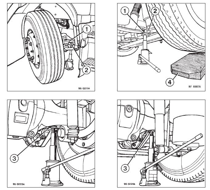 На нашем сайте Вы можете бесплатно скачать (22,6 Mb) справочное пособие по эксплуатации Renault Trucks PREMIUM с моторами 220 dCi, 270 dCi, 320 dCi, 370 dCi, 420 dCi.

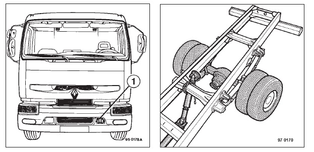
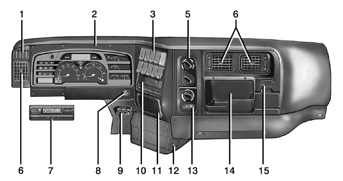
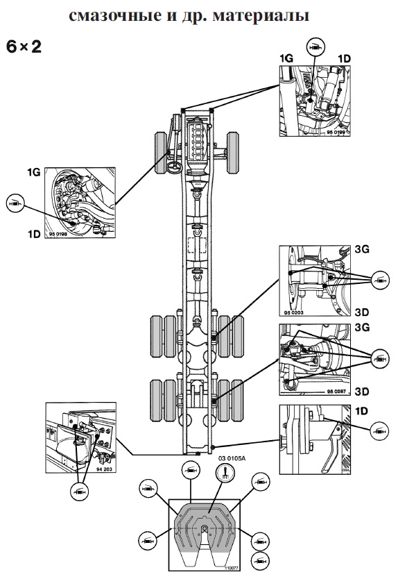
- < Назад
- Вперёд >