
INSTALLATION
C3461M (7/09)
Spectra IV IP Series
Dome System
In-Ceiling
Heavy-Duty In-Ceiling
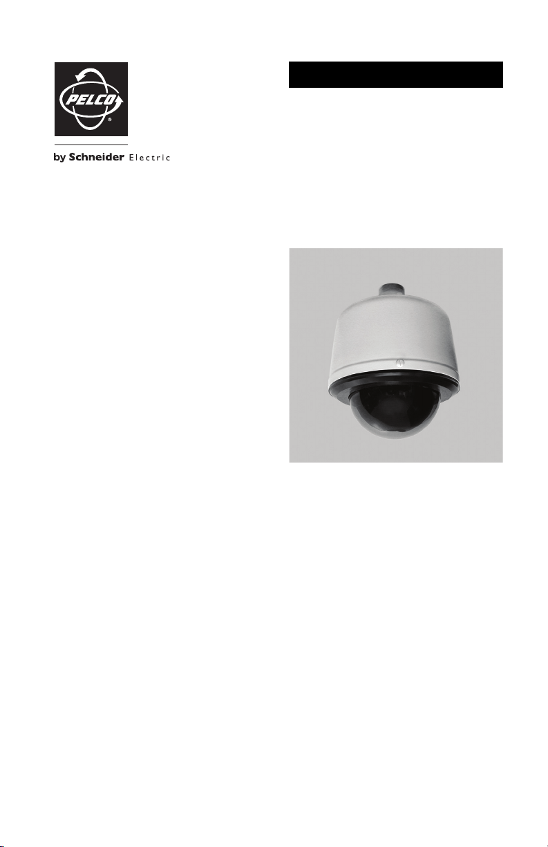
Pendant (shown)
Heavy-Duty Pendant
Stainless Steel Pendant

2 C3461M (7/09)

C3461M (7/09) 3
Contents
Regulatory Notices. . . . . . . . . . . . . . . . . . . . . . . . . . . . . . . . . . . . . . . . . . . . . . . . . . . . . . . . . . . . . . . . . . . . . 6
Legal Notice . . . . . . . . . . . . . . . . . . . . . . . . . . . . . . . . . . . . . . . . . . . . . . . . . . . . . . . . . . . . . . . . . . . . . 6
Open Source Software Notice . . . . . . . . . . . . . . . . . . . . . . . . . . . . . . . . . . . . . . . . . . . . . . . . . . . . . . . 6
Description . . . . . . . . . . . . . . . . . . . . . . . . . . . . . . . . . . . . . . . . . . . . . . . . . . . . . . . . . . . . . . . . . . . . . . . . . . . 7
Models . . . . . . . . . . . . . . . . . . . . . . . . . . . . . . . . . . . . . . . . . . . . . . . . . . . . . . . . . . . . . . . . . . . . . . . . . 7
Parts List. . . . . . . . . . . . . . . . . . . . . . . . . . . . . . . . . . . . . . . . . . . . . . . . . . . . . . . . . . . . . . . . . . . . . . . . 7
Mounting . . . . . . . . . . . . . . . . . . . . . . . . . . . . . . . . . . . . . . . . . . . . . . . . . . . . . . . . . . . . . . . . . . . . . . . . . . . . 8
In-Ceiling . . . . . . . . . . . . . . . . . . . . . . . . . . . . . . . . . . . . . . . . . . . . . . . . . . . . . . . . . . . . . . . . . . . . . . . 8
Heavy-Duty In-Ceiling. . . . . . . . . . . . . . . . . . . . . . . . . . . . . . . . . . . . . . . . . . . . . . . . . . . . . . . . . . . . . . 9
Pendant, Heavy-Duty Pendant, and Stainless Steel . . . . . . . . . . . . . . . . . . . . . . . . . . . . . . . . . . . . . 11
Wiring. . . . . . . . . . . . . . . . . . . . . . . . . . . . . . . . . . . . . . . . . . . . . . . . . . . . . . . . . . . . . . . . . . . . . . . . . . . . . . 12
Installing the Dome Drive. . . . . . . . . . . . . . . . . . . . . . . . . . . . . . . . . . . . . . . . . . . . . . . . . . . . . . . . . . . . . . . 18
Installing the Lower Dome . . . . . . . . . . . . . . . . . . . . . . . . . . . . . . . . . . . . . . . . . . . . . . . . . . . . . . . . . . . . . . 19
In-Ceiling . . . . . . . . . . . . . . . . . . . . . . . . . . . . . . . . . . . . . . . . . . . . . . . . . . . . . . . . . . . . . . . . . . . . . . 19
Heavy-Duty In-Ceiling. . . . . . . . . . . . . . . . . . . . . . . . . . . . . . . . . . . . . . . . . . . . . . . . . . . . . . . . . . . . . 20
Pendant. . . . . . . . . . . . . . . . . . . . . . . . . . . . . . . . . . . . . . . . . . . . . . . . . . . . . . . . . . . . . . . . . . . . . . . . 21
Heavy-Duty Pendant. . . . . . . . . . . . . . . . . . . . . . . . . . . . . . . . . . . . . . . . . . . . . . . . . . . . . . . . . . . . . . 22
Stainless Steel . . . . . . . . . . . . . . . . . . . . . . . . . . . . . . . . . . . . . . . . . . . . . . . . . . . . . . . . . . . . . . . . . . 24
Troubleshooting . . . . . . . . . . . . . . . . . . . . . . . . . . . . . . . . . . . . . . . . . . . . . . . . . . . . . . . . . . . . . . . . . . . . . . 26
Switch Settings . . . . . . . . . . . . . . . . . . . . . . . . . . . . . . . . . . . . . . . . . . . . . . . . . . . . . . . . . . . . . . . . . . . . . . 28
Specifications. . . . . . . . . . . . . . . . . . . . . . . . . . . . . . . . . . . . . . . . . . . . . . . . . . . . . . . . . . . . . . . . . . . . . . . . 37

4 C3461M (7/09)
List of Illustrations
1 Preparing the Ceiling . . . . . . . . . . . . . . . . . . . . . . . . . . . . . . . . . . . . . . . . . . . . . . . . . . . . . . . . . . . . . . 8
2 Attaching the Conduit Fitting, Lock Nut, and Safety Chain Bracket . . . . . . . . . . . . . . . . . . . . . . . . . . 8
3 Marking the Screw Hole Pattern . . . . . . . . . . . . . . . . . . . . . . . . . . . . . . . . . . . . . . . . . . . . . . . . . . . . . 9
4 Installing the Plates . . . . . . . . . . . . . . . . . . . . . . . . . . . . . . . . . . . . . . . . . . . . . . . . . . . . . . . . . . . . . . 10
5 Installing the Heavy-Duty In-Ceiling Back Box. . . . . . . . . . . . . . . . . . . . . . . . . . . . . . . . . . . . . . . . . . 10
6 Attaching the Pendant Back Box to the Mount . . . . . . . . . . . . . . . . . . . . . . . . . . . . . . . . . . . . . . . . . 11
7 Back Box Door . . . . . . . . . . . . . . . . . . . . . . . . . . . . . . . . . . . . . . . . . . . . . . . . . . . . . . . . . . . . . . . . . . 12
8 Removing the TXB-IP . . . . . . . . . . . . . . . . . . . . . . . . . . . . . . . . . . . . . . . . . . . . . . . . . . . . . . . . . . . . . 13
9 Connect the Wiring to the Circuit Board . . . . . . . . . . . . . . . . . . . . . . . . . . . . . . . . . . . . . . . . . . . . . . 14
10 Connecting Audio to the TXB-IP. . . . . . . . . . . . . . . . . . . . . . . . . . . . . . . . . . . . . . . . . . . . . . . . . . . . . 15
11 Routing the Cables in the Back Box. . . . . . . . . . . . . . . . . . . . . . . . . . . . . . . . . . . . . . . . . . . . . . . . . . 16
12 Setting the DIP Switches . . . . . . . . . . . . . . . . . . . . . . . . . . . . . . . . . . . . . . . . . . . . . . . . . . . . . . . . . . 18
13 Installing the In-Ceiling Lower Dome. . . . . . . . . . . . . . . . . . . . . . . . . . . . . . . . . . . . . . . . . . . . . . . . . 19
14 Installing the Heavy-Duty In-Ceiling Lower Dome. . . . . . . . . . . . . . . . . . . . . . . . . . . . . . . . . . . . . . . 20
15 Attaching the Leash to the Pendant Lower Dome . . . . . . . . . . . . . . . . . . . . . . . . . . . . . . . . . . . . . . . 21
16 Installing the Pendant Lower Dome. . . . . . . . . . . . . . . . . . . . . . . . . . . . . . . . . . . . . . . . . . . . . . . . . . 21
17 Installing the O-Ring. . . . . . . . . . . . . . . . . . . . . . . . . . . . . . . . . . . . . . . . . . . . . . . . . . . . . . . . . . . . . . 22
18 Installing the Heavy-Duty Pendant Lower Dome . . . . . . . . . . . . . . . . . . . . . . . . . . . . . . . . . . . . . . . . 23
19 Attaching the Leash to the Stainless Steel Lower Dome . . . . . . . . . . . . . . . . . . . . . . . . . . . . . . . . . 24
20 Installing the Stainless Steel Lower Dome . . . . . . . . . . . . . . . . . . . . . . . . . . . . . . . . . . . . . . . . . . . . 25

C3461M (7/09) 5
List of Tables
A Video Coaxial Cable Requirements . . . . . . . . . . . . . . . . . . . . . . . . . . . . . . . . . . . . . . . . . . . . . . . . . . 17
B 24 VAC/24 VDC Wiring Distances . . . . . . . . . . . . . . . . . . . . . . . . . . . . . . . . . . . . . . . . . . . . . . . . . . . 17
C Troubleshooting the Spectra IV IP Dome System . . . . . . . . . . . . . . . . . . . . . . . . . . . . . . . . . . . . . . . 26
D Switch Settings for SW2 . . . . . . . . . . . . . . . . . . . . . . . . . . . . . . . . . . . . . . . . . . . . . . . . . . . . . . . . . . 28
E Switch Settings for SW1, Pelco P-Type Control . . . . . . . . . . . . . . . . . . . . . . . . . . . . . . . . . . . . . . . . 29
F Switch Settings for SW1, Pelco D-Type Control . . . . . . . . . . . . . . . . . . . . . . . . . . . . . . . . . . . . . . . . 30

6 C3461M (7/09)
Regulatory Notices
This device complies with Part 15 of the FCC Rules. Operation is subject to the following two conditions:
(1) this device may not cause harmful interference, and (2) this device must accept any interference
received, including interference that may cause undesired operation.
RADIO AND TELEVISION INTERFERENCE
This equipment has been tested and found to comply with the limits of a Class B digital device, pursuant to
Part 15 of the FCC Rules. These limits are designed to provide reasonable protection against harmful
interference in a residential installation. This equipment generates, uses, and can radiate radio frequency
energy and, if not installed and used in accordance with the instructions, may cause harmful interference
to radio communications. However there is no guarantee that the interference will not occur in a particular
installation. If this equipment does cause harmful interference to radio or television reception, which can
be determined by turning the equipment off and on, the user is encouraged to try to correct the
interference by one or more of the following measures:
• Reorient or relocate the receiving antenna.
• Increase the separation between the equipment and the receiver.
• Connect the equipment into an outlet on a circuit different from that to which the receiver is
connected.
• Consult the dealer or an experienced radio/TV technician for help.
You may also find helpful the following booklet, prepared by the FCC: “How to Identify and Resolve
Radio-TV Interference Problems.” This booklet is available from the U.S. Government Printing Office,
Washington D.C. 20402.
Changes and modifications not expressly approved by the manufacturer or registrant of this equipment can
void your authority to operate this equipment under Federal Communications Commission’s rules.
This Class B digital apparatus complies with Canadian ICES-003.
Cet appareil numérique de la classe B est conforme à la norme NMB-003 du Canada.
LEGAL NOTICE
SOME PELCO EQUIPMENT CONTAINS, AND THE SOFTWARE ENABLES, AUDIO/VISUAL AND RECORDING
CAPABILITIES, THE IMPROPER USE OF WHICH MAY SUBJECT YOU TO CIVIL AND CRIMINAL PENALTIES.
APPLICABLE LAWS REGARDING THE USE OF SUCH CAPABILITIES VARY BETWEEN JURISDICTIONS AND
MAY REQUIRE, AMONG OTHER THINGS, EXPRESS WRITTEN CONSENT FROM RECORDED SUBJECTS.
YOU ARE SOLELY RESPONSIBLE FOR INSURING STRICT COMPLIANCE WITH SUCH LAWS AND FOR
STRICT ADHERENCE TO ANY/ALL RIGHTS OF PRIVACY AND PERSONALTY. USE OF THIS EQUIPMENT
AND/OR SOFTWARE FOR ILLEGAL SURVEILLANCE OR MONITORING SHALL BE DEEMED UNAUTHORIZED
USE IN VIOLATION OF THE END USER SOFTWARE AGREEMENT AND RESULT IN THE IMMEDIATE
TERMINATION OF YOUR LICENSE RIGHTS THEREUNDER.
OPEN SOURCE SOFTWARE NOTICE
This product includes certain open source or other software originated from third parties that is subject to
the GNU General Public License (GPL), GNU Library/Lesser General Public License (LGPL) and different
and/or additional copyright licenses, disclaimers and notices.
The exact terms of GPL, LGPL and some other licenses are provided to you with this product. Please refer
to the exact terms of the GPL and LGPL at www.fsf.org (Free Software Foundation) and
www.opensource.org (Open Source Initiative) regarding your rights under said license. You may obtain a
complete corresponding machine-readable copy of the source code of such software under the GPL or
LGPL by sending your request to digitalsupport@pelco.com and the subject line should read Source Code
Request. You will then receive a link in the e-mail for you to download the source code.
This offer is valid for a period of three (3) years from the date of the distribution of this product by Pelco.

C3461M (7/09) 7
Description
Spectra
®
IV IP was designed with ease of installation and ease of maintenance in mind. Each dome
system consists of three components: a back box, a dome drive, and a lower dome. Spectra IV IP back box
options include the following models: environmental in-ceiling (ideal for outdoor soffits), indoor in-ceiling,
standard and environmental pendant, heavy-duty, and stainless steel. Depending on the dome drive model
with which it will be used, a back box can be ordered with or without built-in back box memory. This
memory can be used to store camera and location-specific dome settings, including labels, presets,
patterns, and zones.
MODELS
PARTS LIST
BB4N-F In-ceiling, black, with back box memory
BB4N-F-E In-ceiling, black, environmental, with back box memory
BB4N-PB Pendant mount, black, standard, with back box memory
BB4N-PG Pendant mount, gray, standard, with back box memory
BB4N-PG-E Pendant mount, gray, environmental, with back box memory
BB4NT-F In-ceiling, black
BB4NT-F-E In-ceiling, black, environmental
BB4NT-PB Pendant mount, black, standard
BB4NT-PG Pendant mount, gray, standard
BB4NT-PG-E Pendant mount, gray, environmental
BB4NHD-F Heavy-duty, in-ceiling, gray, with back box memory
BB4NHD-PG Heavy-duty, pendant, gray, with back box memory
BB4NHD-PG-E Heavy-duty, environmental pendant, gray, with back box memory
BB4N-PSG-E Stainless steel, environmental pendant, gray 316 SS, with back box memory
Qty Description
1 Back box
1 Thread compound (pendant, heavy-duty pendant, and stainless steel models only)
8 Screws, 10-32 x 3-inch, Phillips flat head (heavy-duty in-ceiling model only)
1 Important Safety Instructions manual
1 Installation manual
1 Operation/Configuration manual
1 Resource disc
8 C3461M (7/09)
Mounting
IN-CEILING
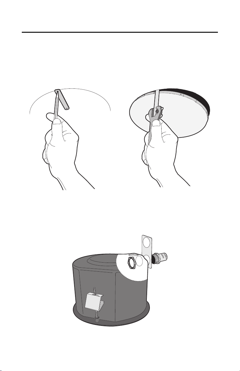
1. Prepare the ceiling (refer to Figure 1):
a. Locate the center point of the mounting location, and insert the compass tool into the ceiling.
b. Place the end of a pencil in the hole on the end of the compass tool, and draw a circle.
c. Cut out the circle.
Figure 1. Preparing the Ceiling
2. Attach a conduit fitting (not supplied), lock nut (not supplied), and safety chain bracket (refer to
Figure 2).
3. Install a safety chain/cable (not supplied), which will support up to 16 pounds (7.3 kg).
Figure 2. Attaching the Conduit Fitting, Lock Nut, and Safety Chain Bracket
C3461M (7/09) 9
4. Open the hinged door to the back box by pushing the tab lock toward the wall of the unit and lifting
the door open.
5. Pull the wiring into the back box through the conduit fitting.
6. Connect all required wiring (refer to Wiring on page 12).
7. Install the back box by compressing the spring clips and pushing the back box through the hole.
8. Tighten the screws until you hear a clicking noise.
HEAVY-DUTY IN-CEILING
1. Prepare the ceiling (refer to Figure 1 on page 8):
a. Locate the center point of the mounting location, and insert the compass tool into the ceiling.
b. Place the end of a pencil in the hole on the end of the compass tool, and draw a circle.
c. Cut out the circle.
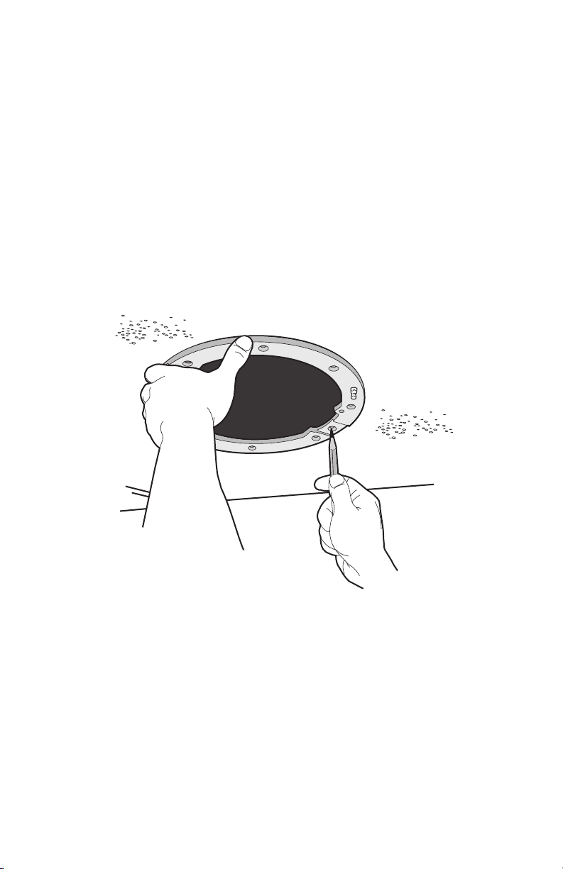
2. Use the mounting ring as a template to mark the screw hole pattern onto the mounting surface.
3. Prepare the holes.
Figure 3. Marking the Screw Hole Pattern
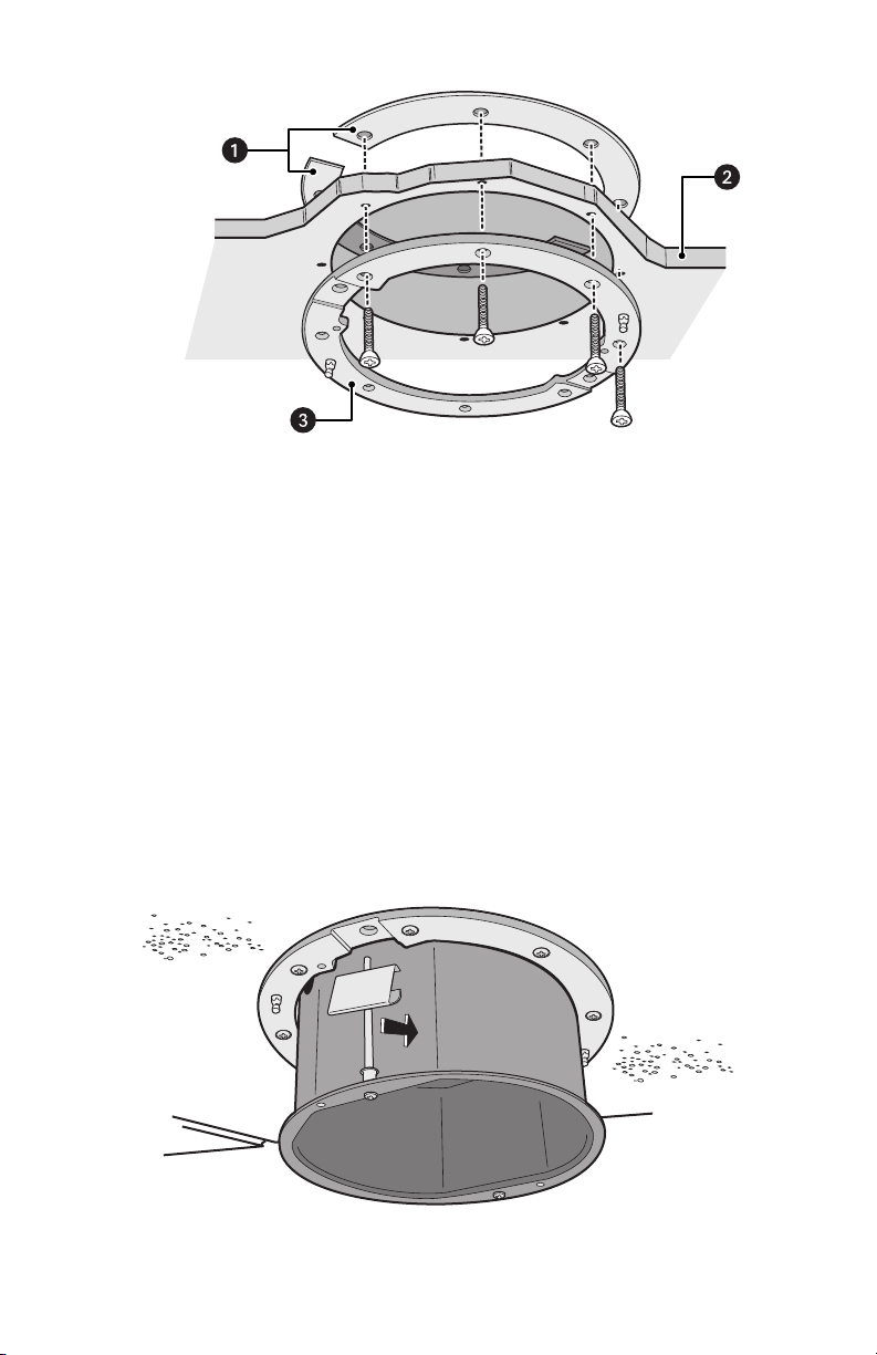
4. Install the mounting plates (refer to Figure 4 on page 10). Use the eight 10-32 x 3-inch screws
(supplied) to install the mounting ring and the two back mounting plates.
a. Line up the mounting ring with the eight fastener holes.
b. Feed one back mounting plate through the hole in the ceiling. Line up the plate with the four
fastener holes.
c. Install fasteners through the mounting ring, ceiling, and out the back mounting plate.
d. Install the second back mounting plate.
10 C3461M (7/09)
Figure 4. Installing the Plates
5. Attach a conduit fitting (not supplied), lock nut (not supplied), and safety chain bracket (refer to
Figure 2 on page 8).
6. Install a safety chain/cable (not supplied), which will support up to 16 pounds (7.3 kg).
7. Open the hinged door to the back box by pushing the tab lock toward the wall of the unit and lifting
the door open.
8. Pull the wiring into the back box through the conduit fitting.
9. Connect all required wiring (refer to Wiring on page 12).
10. Install the back box by compressing the spring clips and pushing the back box through the hole (refer
to Figure 5).
11. Tighten the screws until you hear a clicking noise.
Figure 5. Installing the Heavy-Duty In-Ceiling Back Box
ì
Back Mounting Plates
î
Ceiling
ï
Mounting Ring
C3461M (7/09) 11
PENDANT, HEAVY-DUTY PENDANT, AND STAINLESS STEEL
1. Install the mount for the pendant dome. Refer to the instructions supplied with the mount.
NOTE: If the mount is outdoors, make sure it is properly sealed to keep moisture out.
2. Open the hinged door to the back box by pushing the tab lock towards the wall of the unit and lifting
the door open.
3. Pull the wiring into the back box.
4. Connect all required wiring (refer to Wiring on page 12).
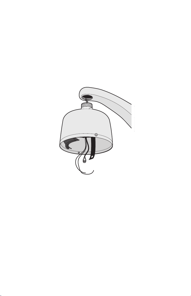
5. Screw the back box onto the mount (refer to Figure 6). If outdoors, apply thread compound (supplied)
to the threads on the back box.
NOTE: Thread compound must be applied. Not doing so may prevent the units from being separated
in the future.
Figure 6. Attaching the Pendant Back Box to the Mount
12 C3461M (7/09)
Wiring
1. Open the hinged door to the back box by pushing the tab lock toward the wall of the unit and lifting
the door open (refer to Figure 7).
Figure 7. Back Box Door
C3461M (7/09) 13
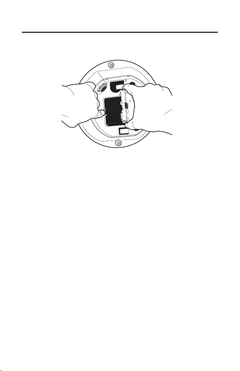
2. Remove the TXB-IP from the back box circuit board (refer to Figure 8):
a. Loosen the captive screw on the TXB-IP.
b. Carefully unplug the TXB-IP from the back box circuit board.
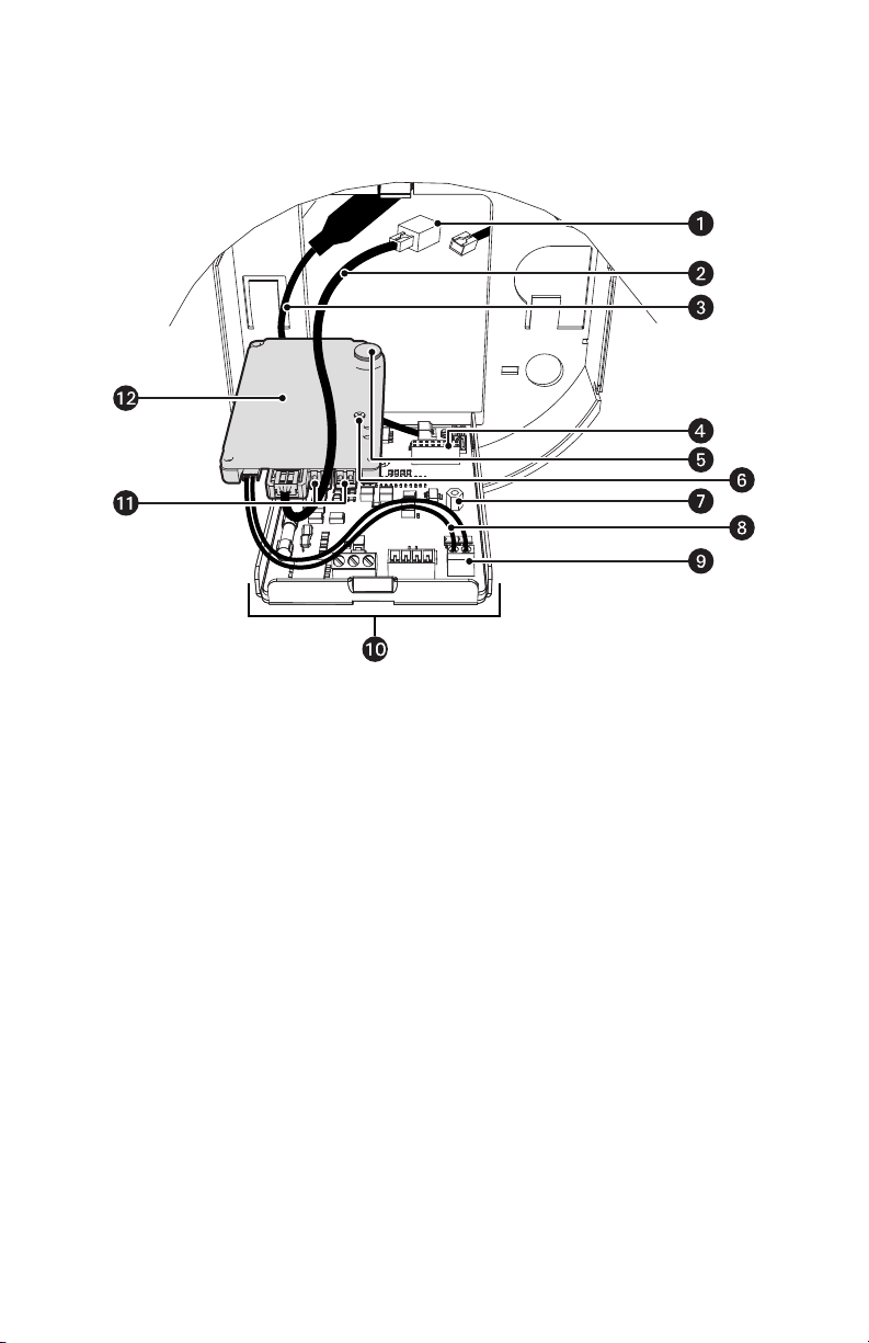
Figure 8. Removing the TXB-IP
ì
RJ-45 Coupler
s
Standoff
î
Ethernet Cable
t
Video UTP Cable
ï
Video Coaxial Cable
u
UTP Connector
ñ
16-Pin Connector
~í
Back Box Circuit Board
ó
Heat Sink Standoff
~â
Audio Connectors
r
Captive Screw
~ä
TXB-IP
+ —
14 C3461M (7/09)
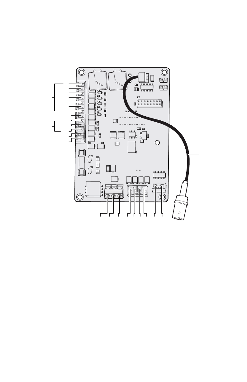
3. Connect the auxiliary, alarm, and other wiring to the back box circuit board (refer to Figure 9).
NOTES:
• Aux 1: Maximum 2 A at low voltage (<40 V)
Aux 2: Maximum 30 mA at 32 VDC
• If you are installing an environmental back box in a railway application, attach a ground wire
from the circuit board power connector to a structural ground using at least 18-gauge wire.
Figure 9. Connect the Wiring to the Circuit Board
VIDEO
UTP+ UTP-RX- RX+ TX+TX-PWR- PWR+GND
AUX2
GND
GND
NO
NC
COM
7
6
5
4
3
2
1
ALARMS
AUX1
 Loading…
- camfil farr gold series dust collector manual
- A&D – FX-120i/FX-200i/FX-300i/FX1200i/FX2000i/FX3000i
- Acer – XD1270
- KANSAI DX9902-3U-LK-UTC pdf manual
- mamiya 645 pro tl manual
- AudioSource AudioSource Home Audio Powered Subwoofer Manual
- AeroGarden – PRO100
- z4z24ua aba
- ryobi 14.4 volt battery charger manual
- Autostart AS-1221 Manual
- ltr 450 stator
- 2008 ltr 450
- Audio-Technica ATH-M35 Manual
- Atlantis Land A05-19BM-F02 Manual
- SINGER 211U257A pdf manual
- Belkin F6C350ZSER-SB Manual
- hp 2580 solvent ink
- blackmagic studio 4k manual
- 1999 rm 125 top speed
- 2004 suzuki eiger specs

OPERATOR’S MANUAL
MANUEL de L’UTILISATEUR
MANUAL del OPERADOR
Catalog No.
No de Catalogue
Catálogo No.
48-59-0245
POWER-PLUS 9.6V — 18V UNIVERSAL CHARGER CHARGEUR UNIVERSEL 9.6 V — 18 V POWER PLUS CARGADOR UNIVERSAL POWER-PLUS DE 9.6V — 18V
TO REDUCE THE RISK OF INJURY, USER MUST READ AND UNDERSTAND OPERATOR’S MANUAL.
AFINDERÉDUIRELERISQUEDEBLESSURES,L’UTILISATEURDOITLIREETBIENCOMPRENDRELEMANUELDE L’UTILISATEUR.
PARA REDUCIR EL RIESGO DE LESIONES, EL USUARIO DEBE LEER Y ENTENDER EL MANUAL DEL OPERADOR.

IMPORTANT SAFETY INSTRUCTIONS
SAVE THESE INSTRUCTIONS
This manual contains important safety and operating instructions for battery chargers. Before using the battery charger, read this manual as well as any labels on the charger, battery pack and tool.
1.CAUTION! To reduce the risk of injury, charge only MILWAUKEE 9.6, 12, 14.4 and 18 Volt Power Plus Battery packs in this charger. Other types of batteries may explode, causing personal injury or damage.
2.AVOID DANGEROUS ENVIRONMENTS. Do not use charger in rain, snow, damp or wet locations. Do not use battery pack or charger in the presence of explosive atmospheres (gaseous fumes, dust or flammable materials) because sparks may be generated when inserting or removing battery pack, possibly causing fire.
3.CHARGE IN A WELL VENTILATED AREA. Do not block charger vents. Keep them clear to allow proper ventilation. Do not allow smoking or open flames near a charging battery pack. Vented gases may explode.
4.MAINTAIN CHARGER CORD. When unplugging charger, pull plug rather than cord to reduce the risk of damage to the electrical plug and cord. Never carry charger by its cord. Keep cord from heat, oil and sharp edges. Make sure cord will not be stepped on, tripped over or subjected to damage or stress. Do not use charger with damaged cord or plug. Have a damaged cord replaced immediately with identical replacement parts (see “Maintenance”).
5.DO NOT USE CHARGER OR BATTERY PACK IF it has received a sharp blow, been dropped or damaged in any way. Do not disassemble. Incorrect reassembly may result in the risk of electric shock, fire or exposure to battery fluids. If it is damaged, take it to a MILWAUKEE service facility.
6.CHARGER IS RATED FOR 120 VOLT AC ONLY. Charger must be plugged into an appropriate receptacle.
7.USE ONLY RECOMMENDEDATTACHMENTS. Use of an attachment not recommended or sold by the battery charger manufacturer may result in a risk of fire, electric shock or personal injury.
8.DO NOT USE AN EXTENSION CORD UNLESS IT IS ABSOLUTELY NECESSARY. Using the wrong, damaged or improperly wired exten-
sion cord could result in the risk of fire and electrical shock. If an extension cord must be used, plug the charger into a properly wired 16 gauge or larger extension cord with pins that are the same number, size and shape as the pins on the charger. Make sure that the extension cord is in good electrical condition.
9.DO NOT BURN, MUTILATE OR DISASSEMBLE BATTERY PACK.
The battery pack can explode in a fire. Mutilation may expose battery fluids, causing burns.
10.BATTERY FLUIDS CAUSE SERIOUS CHEMICAL BURNS. Never allow contact with skin or eyes. If a damaged battery pack leaks battery fluids, use rubber or neoprene gloves to dispose of it. If skin is exposed to battery fluids, wash with soap and water and rinse with vinegar. Remove and dispose of contaminated clothing. If eyes are affected, immediately flush with water for 15 minutes and seek medical attention.
11.DO NOT SHORT CIRCUIT. A battery pack will short circuit if a metal object makes a connection between the positive and negative contacts on the battery pack. Do not place a battery pack near anything that may cause a short circuit, such as coins or keys in your pocket. A short circuited battery pack may cause fire and personal injury.
12.UNPLUG CHARGER when not in use.
13.TO REDUCE THE RISK OF ELECTRIC SHOCK, always unplug charger before cleaning or maintenance, turning off controls will not reduce this risk. Use a Ground Fault Circuit Interrupter (GFCI) to reduce shock hazards.
14.STORE YOUR BATTERY PACK AND CHARGER in a cool, dry place. Do not store battery pack where temperatures may exceed 120°F (50°C) such as in a vehicle or metal building during the summer. Charger will charge the battery at the most rapid rate when the temperature is between 41°F (5°C) and 113°F (45°C). When the battery temperature is outside that range, charging will take longer.
READ AND SAVE ALL INSTRUCTIONS FOR
FUTURE REFERENCE.
FUNCTIONAL DESCRIPTION
|
1. |
Red control light |
||||
|
2 |
3 |
4 |
Light off indicates: |
Charger is ready for operation |
|
|
Battery pack is charged |
|||||
|
1 |
|||||
|
5 |
Maintenance charging |
||||
|
Continuous light indicates: |
Charging (Fast, if battery |
||||
|
temperature is between 41°F |
|||||
|
(5°C) and 113°F (45°C) |
|||||
|
6 |
Flashing light indicates: |
Battery pack is too hot or too cold |
|||
|
(Charging will begin automatically |
|||||
|
when battery reaches correct |
|||||
|
charging temperature) |
|||||
|
2. |
Instruction label |
||||
|
3. |
Electrical contacts |
||||
|
7 |
4. |
Battery pack port |
|||
|
8 |
5. |
Vents |
|||
|
6. |
Nameplate (on back of charger) |
||||
|
7. |
Key hole slots: |
Mounts charger vertically |
|||
|
(on bottom of charger) |
|||||
|
8. |
Cord wrap: |
Stores excess cord |
|||
|
(on bottom of charger) |
Page 2
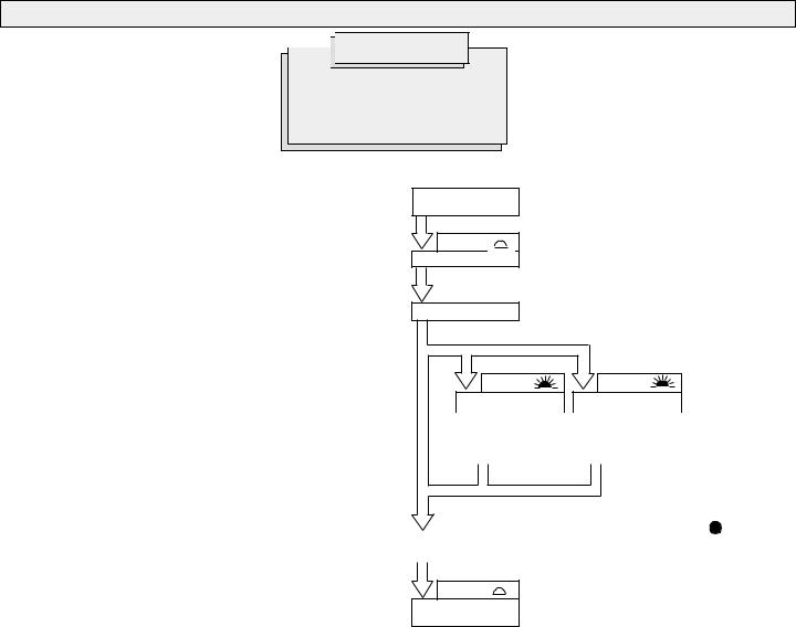
OPERATION


 WARNING!
Charge only MILWAUKEE 9.6, 12, 14.4 and 18 Volt Power Plus battery
packs in this charger. Other types of batteries may explode causing personal injury and damage.
When to charge the Power Plus battery pack
Charge your battery pack before you use your tool for the first time and when your tool no longer performs with the power and torque needed for the job. Never completely discharge the battery pack.
New battery packs reach full loading capacity after 4-5 chargings and dischargings. Battery packs which have not been used for some time should be recharged before use.
Standard charging times
Standard charging time is approximately one hour. Charging time varies depending on the battery temperature, charge needed and the type of battery pack being charged. For example, if the battery pack does not require a full charge, the charging time will be less than one hour.
Effects of temperature on charging
Battery packs are affected by temperature. The charger will sense battery temperature and will charge the battery at the most rapid rate when its temperature is between 41°F (5°C) and 113°F (45°C). When the battery temperature is outside of this range, charging will occur at a slower rate to prevent damage to battery.
Automatic start
When a hot or cold battery pack is inserted into the charger, charging will begin automatically once the battery reaches the correct charging temperature.
Maintenance charge
Batteries discharge at a rate of about 1% per day. The Maintenance Charge feature keeps the battery pack fully charged when the battery pack is stored in a charger that is plugged in. The Maintenance Charge automatically begins after the battery pack is fully charged. During Maintenance Charge, the control light will be off.
Charging the Power Plus Battery Pack
Connect Charger to AC
Power Source
ChargerReady
Insert Battery
|
Flashing |
Flashing |
|
Light |
Light |
|
Battery too hot |
Battery too cold |
|
|
over140°F (60°C) |
less than 14°F (-10°C) |
|
|
Charge pending until |
Charge pending until |
|
|
battery temperature is |
battery temperature is |
|
|
below 140°F (60°C). |
above 14°F (-10°C). |
|
|
Continuous |
|||
|
Light |
|||
|
Batterytemperature |
Batterytemperature |
||
|
41°F — 113°F (5°C — 45°C) |
14°F — 41°F (-10°C — 5°C) or 113°F — 140°F (45°C — 60°C) |
||
|
Fast charging |
Charging at a slower rate |
Battery is charged/
Maintenance charging
Page 3

MAINTENANCE


 WARNING!
To reduce the risk of injury, always unplug the charger and remove the battery pack from the charger or tool before performing any maintenance. Never disassemble the tool, battery pack or charger. Contact a
MILWAUKEE service facility for ALL repairs.
Keep your tool, battery pack and charger in good repair by adopting a regular maintenance program. After six months to one year, depending on use, return the tool, battery pack and charger to a MILWAUKEE service facility for:
•Lubrication
•Mechanical inspection and cleaning (gears, spindles, bearings, housing, etc.)
•Electrical inspection (battery pack, charger, motor)
•Testing to assure proper mechanical and electrical operation
Maintaining tool
If the tool does not start or operate at full power with a fully charged battery pack, return the tool, charger and battery pack to a MILWAUKEE service facility for repairs (see “Repairs”).
Maintaining battery pack
MILWAUKEE Nickel-Cadmium and Nickel-Metal Hydride battery packs will operate for many years and/or hundreds of cycles when they are maintained and used according to these instructions.
A battery pack that is stored for six months without being used will discharge itself. Batteries discharge at a rate of about 1% per day. Charge the battery every six months even if it is unused to maximize battery life. Do not tape the tool’s trigger in the ON position and leave the tool unattended as this may discharge the battery to a point where it will no longer be able to recharge. If the battery pack will not recharge, leave the battery removed from the charger for 24 hours. This allows the battery pack to recover from deep discharge. Reinsert the battery pack onto the charger to recharge to full capacity. Use a MILWAUKEE battery pack only until it no longer performs with the power and torque needed for your application.
Store your battery pack in a cool, dry place. Do not store it where the temperature may exceed 120° F (50° C) such as in a vehicle or metal building during the summer. High temperatures will overheat the battery pack, reducing battery life. If it is stored for several months, the battery pack will gradually lose its charge. One to three cycles of charging and discharging through normal use will restore the capacity of the battery pack. During the life of the battery pack, the operating time between charges becomes shorter. If the operating time becomes extremely short after a proper charge, the usable life of the battery pack has been reached and it should be replaced.
WARNING!
To reduce the risk of injury and damage, never immerse your tool, battery pack or charger in liquid or allow a liquid to flow inside them.
Cleaning
Clean dust and debris from charger and tool vents. Keep tool handles clean, dry and free of oil or grease. Use only mild soap and a damp cloth to clean the tool, battery pack and charger since certain cleaning agents and solvents are harmful to plastics and other insulated parts. Some of these include gasoline, turpentine, lacquer thinner, paint thinner, chlorinated cleaning solvents, ammonia and household detergents containing ammonia. Never use flammable or combustible solvents around tools.
WARNING!
To reduce the risk of explosion, never burn a battery pack even if it is damaged, dead or completely discharged.
Disposing of nickel-cadmium battery packs
Nickel-Cadmium battery packs are recyclable. Under various state and local laws, it may be illegal to dispose of this battery into the municipal waste stream. Return the battery pack to the nearestMILWAUKEE Branch Office/ Service Center or dispose of your battery pack according to federal, state and local regulations.
Disposing of nickel-metal hydride battery packs
Nickel-Metal Hydride battery packs are recyclable but may also be disposed into the municipal waste stream. To recycle, return the battery pack to the nearest MILWAUKEE Branch Office/Service Center. Always dispose of your battery pack according to federal, state and local regulations.
Repairs
For repairs, return the tool, battery pack and charger to the nearest service center listed on the back cover of this operator’s manual.
Battery pack warranty
Battery packs for cordless tools are warranted for one year from the date of purchase.
WARRANTY
EveryMILWAUKEE tool is thoroughly inspected and tested before leaving our manufacturing facilities. Should any trouble develop, return the complete tool prepaid to our Corporate Office, Branch Office/Service Center or nearest Authorized MILWAUKEE Service Station. If inspection shows the trouble is caused by defective workmanship or material, all repairs will be made without charge, and the tool will be returned, transportation prepaid. Battery packs for cordless tools are warranted for one year from the date of purchase.
This warranty does not apply where: (1) repairs or attempted repairs have been made by persons other than MILWAUKEE personnel or Authorized Service Station personnel; (2) repairs are required because of normal wear; (3) the tool has been abused or involved in an accident;
(4) misuse is evident, such as caused by overloading the tool beyond its rated capacity; (5) the tool has been used after partial failure or (6) the tool has been used with an improper accessory. No other warranty, written or verbal, is authorized.
Page 4
Loading…
 Loading…
C3468M-RU (4/10)
9
Описание
Система Spectra
®
IV IР рассчитана на простоту установки и простоту в эксплуатации. Каждая
купольная система состоит из трех элементов: монтажная коробка, купольный привод и плафон.
Для системы Spectra IV IР предлагаются следующие модели монтажных коробок: для установки
в потолке с защитой от внешних воздействий (идеально для наружных софитов), для установки
в потолке в помещениях, подвесные модели стандартного исполнения и с защитой от внешних
воздействий, модель для тяжелых условий эксплуатации и модель из нержавеющей стали.
В зависимости от используемой модели купольного привода, монтажная коробка может быть
заказана как с запоминающим устройством, так и без него. Эта память может использоваться
для хранения данных о настройке телекамеры и данной конкретной купольной системы,
включая метки, предустановки, циклограммы и зоны.
МОДЕЛИ
BB4E-F
Модель для установки внутри потолка, черного цвета, с запоминающим
устройством
BB4E-F-E
Модель для установки внутри потолка, черного цвета, с запоминающим
устройством, с защитой от внешних воздействий
BB4E-PB
Модель для подвесного исполнения, черного цвета, стандартная,
с запоминающим устройством
BB4E-PG
Модель для подвесного исполнения, серого цвета, стандартная,
с запоминающим устройством
BB4E-PG-E
Модель для подвесного исполнения, серого цвета, с защитой от внешних
воздействий, с запоминающим устройством
BB4EHD-F
Модель для установки внутри потолка, для эксплуатации в тяжелых
условиях, серого цвета, с запоминающим устройством
BB4EHD-PG
Модель для подвесного исполнения, для эксплуатации в тяжелых
условиях, серого цвета, с запоминающим устройством
BB4EHD-PG-E Модель для подвесного исполнения, для эксплуатации в тяжелых
условиях, с защитой от внешних воздействий, серого цвета,
с запоминающим устройством
BB4E-PSG-E
Модель для подвесного исполнения, из нержавеющей стали марки 316,
с защитой от внешних воздействий, серого цвета, с запоминающим
устройством
КОМПЛЕКТАЦИЯ
Описание
Монтажная коробка
Состав для резьбы (только в подвесных моделях для обычных и тяжелых условий
эксплуатации и в моделях из нержавеющей стали)
Винты, 10-32 x 3″, с крестообразным шлицем, с потайной головкой
(только в моделях для тяжелых условий эксплуатации, устанавливаемых в потолке)
Инструкция по важнейшим правилам техники безопасности
Руководство по установке
Руководство по эксплуатации и настройке конфигурации
Компакт-диск с ресурсами
Кол-во
1
1
8
1
1
1
1
User Manual for Pelco BB4NHD-PG-E Heavy Duty Spectra IV IP Environmental Pendant Mount Back BoxClick to enlarge the picture Contents of the user manual for the Pelco BB4NHD-PG-E Heavy Duty Spectra IV
|
||||||||||||||||||||||
|
User manual for the Pelco BB4NHD-PG-E Heavy Duty Spectra IV contain basic instructions that need to be followed during installation and operation. Before starting your appliance, the user manual should be read through carefully. Follow all the safety instructions and warnings, and be guided by the given recommendations. User manual is an integral part of any Pelco product, and if it is sold or transferred, they should be handed over jointly with the product. Following the instructions for use is an essential prerequisite for protecting health and property during use, as well as recognition of liability on the part of the manufacturer for possible defects should you make a warranty claim. Download an official Pelco user manual in which you will find instructions on how to install, use, maintain and service your product. And do not forget – unsuitable use of a Pelco product will considerably shorten its lifespan! |
||||||||||||||||||||||
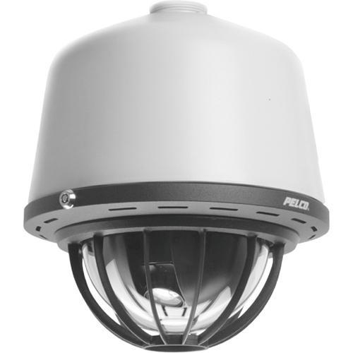
Product descriptionThe Pelco BB4NHD-PG-E is the back box portion of a Heavy-Duty Spectra IV IP Series PTZ dome camera system. All Pelco Spectra series camera systems are made up of three key components — a back box (body), dome drive (camera) and lower dome (bubble). This type of configuration will allow you to easily swap, replace or upgrade a part of the camera without having to purchase a whole new system.
In the Box Pelco BB4NHD-PG-E Heavy Duty Spectra IV IP Environmental Pendant Mount Back Box (Gray) Table of Contents |
||||||||||||||||||||||
Upload User Manual Have you got an user manual for the Pelco BB4NHD-PG-E Heavy Duty Spectra IV IP Environmental Pendant Mount Back Box in electronic form? Please send it to us and help us expand our library of instruction manuals. To upload the product manual, we first need to check and make sure you are not a robot. After that, your «Submit Link» or «Upload File» will appear.
Contents of the user manual for the Pelco BB4NHD-PG-E Heavy Duty Spectra IV
|
||||||||||||||||||||||
|
User manual for the Pelco BB4NHD-PG-E Heavy Duty Spectra IV contain basic instructions that need to be followed during installation and operation. Before starting your appliance, the user manual should be read through carefully. Follow all the safety instructions and warnings, and be guided by the given recommendations. User manual is an integral part of any Pelco product, and if it is sold or transferred, they should be handed over jointly with the product. Following the instructions for use is an essential prerequisite for protecting health and property during use, as well as recognition of liability on the part of the manufacturer for possible defects should you make a warranty claim. Download an official Pelco user manual in which you will find instructions on how to install, use, maintain and service your product. And do not forget – unsuitable use of a Pelco product will considerably shorten its lifespan! |
||||||||||||||||||||||
Product descriptionThe Pelco BB4NHD-PG-E is the back box portion of a Heavy-Duty Spectra IV IP Series PTZ dome camera system. All Pelco Spectra series camera systems are made up of three key components — a back box (body), dome drive (camera) and lower dome (bubble). This type of configuration will allow you to easily swap, replace or upgrade a part of the camera without having to purchase a whole new system.
In the Box Pelco BB4NHD-PG-E Heavy Duty Spectra IV IP Environmental Pendant Mount Back Box (Gray) Table of Contents |
||||||||||||||||||||||
Upload User Manual Have you got an user manual for the Pelco BB4NHD-PG-E Heavy Duty Spectra IV IP Environmental Pendant Mount Back Box in electronic form? Please send it to us and help us expand our library of instruction manuals. To upload the product manual, we first need to check and make sure you are not a robot. After that, your «Submit Link» or «Upload File» will appear.
Please enter here the link to the user manual of this product:
Enter here the file with the user manual of this product from your computer/phone:(60MB max; Permitted formats: PDF)
0%
Technical parametersPelco BB4NHD-PG-E Specs
Rating70% users recommend this product to others. And what about you? Please enter here the link to the user manual of this product:
Enter here the file with the user manual of this product from your computer/phone:(60MB max; Permitted formats: PDF)
0% Technical parametersPelco BB4NHD-PG-E Specs
Rating70% users recommend this product to others. And what about you? This product has already been rated by 68 owners. Add your rating and experience with the product. Discussion Ask our technicians if you have a problem with your settings, The discussion is empty — enter the first post Post a new topic / query / comment: Items marked with * are required. Your name *: E-mail : Subject *: Message *: Your email address will not be displayed. Do not forget to fill it in if you want to receive a reply to your enquiry/contribution. Processing of personal data in accordance with GDPR |




| Request for user manual |
|
You can’t find the operation manual you are looking for? Let us know and we will try to add the missing manual:
I’m looking for a manual / Request for manual Current requests for instruction manuals: Epson -Expression 12000XL… User manual for Toyo-View 8×10 810MII Field View Camera… I just ordered this tv and it didn’t come with instructions. I need some assistance figuring out all of the capabilities. But I love it so far! I j… CyberPowerPC — Gamer Xtreme Gaming Desktop — Intel Core i7-10700F — 16GB Memory — NVIDIA GeForce RTX 2060 SUPER — 1TB HDD + 500GB SSD — Black… Riviera pocket quadcopter 2.4ghz… |
| Discussion |
|
Latest contributions to the discussion:
Password — Change Foot bedal fsb 106a RCF 8003 The Manual to repair Bulbs & batteries Can I use the pom gear power2go 10400 in a foreign country? Thanks, |
What our users say about us:
Peter Morgan: «Thanks for this website! With help from your instructions I’ve got my dishwasher working again.»
Nick Jackson: «Your site’s been a massive help because the user manual didn’t come with the product. Thanks a lot.»
Leslie Scott: «I finally found the user’s guide with you that I couldn’t find anywhere else! Totally happy!»

Ask our technicians if you have a problem with your settings,
or if anything is unclear in the user manual you have downloaded.
You can make use of our moderated discussion.
The discussion is public and helps other users of our website who may be encountering similar problems.
The discussion is empty — enter the first post
Post a new topic / query / comment:
Items marked with * are required.
Your name *:
E-mail :
Subject *:
Your email address will not be displayed. Do not forget to fill it in if you want to receive a reply to your enquiry/contribution.
Processing of personal data in accordance with GDPR
| Request for user manual |
|
You can’t find the operation manual you are looking for? Let us know and we will try to add the missing manual:
I’m looking for a manual / Request for manual Current requests for instruction manuals: Epson -Expression 12000XL… User manual for Toyo-View 8×10 810MII Field View Camera… I just ordered this tv and it didn’t come with instructions. I need some assistance figuring out all of the capabilities. But I love it so far! I j… CyberPowerPC — Gamer Xtreme Gaming Desktop — Intel Core i7-10700F — 16GB Memory — NVIDIA GeForce RTX 2060 SUPER — 1TB HDD + 500GB SSD — Black… Riviera pocket quadcopter 2.4ghz… |
| Discussion |
|
Latest contributions to the discussion:
Password — Change Foot bedal fsb 106a RCF 8003 The Manual to repair Bulbs & batteries Can I use the pom gear power2go 10400 in a foreign country? Thanks, |
What our users say about us:
Peter Morgan: «Thanks for this website! With help from your instructions I’ve got my dishwasher working again.»
Nick Jackson: «Your site’s been a massive help because the user manual didn’t come with the product. Thanks a lot.»
Leslie Scott: «I finally found the user’s guide with you that I couldn’t find anywhere else! Totally happy!»
Всемирная
штаб
—
квартира
компании
Pelco, Inc.:
3500 Pelco Way, Clovis, California 93612-5699 USA
США
и
Канада
Тел
.: (800) 289-9100 •
Факс
: (800) 289-9150
Международный
Тел
.: +1 (559) 292-1981 •
Факс
: +1 (559) 348-1120
www.pelco.com
МОДЕЛИ
СИСТЕМ
И
СОСТАВНЫХ
ЧАСТЕЙ
НОМЕРА
МОДЕЛЕЙ
СИСТЕМЫ
НОМЕРА
МОДЕЛЕЙ
КОМПОНЕНТОВ
Pelco,
логотип
Pelco, Coaxitron, Digital Sentry, Endura
и
Spectra
являются
зарегистрированными
товарными
знаками
компании
Pelco, Inc.
LowLight
является
товарным
знаком
компании
Pelco, Inc.
Все
наименования
изделий
и
услуг
,
указанные
в
настоящем
документе
,
являются
товарными
знаками
или
зарегистрированными
товарными
знаками
соответствующих
компаний
.
Отсутствие
товарного
знака
или
зарегистрированного
товарного
знака
в
настоящем
документе
не
представляет
собой
отказа
от
прав
интеллектуальной
собственности
.
Технические
характеристики
и
сведения
о
наличии
изделия
могут
быть
изменены
без
уведомления
.
© 2009 Pelco, Inc.
Все
права
защищены
.
Тип
Цвет
монтажной
коробки
Плафон
23X,
для
дневного
и
ночного
наблюдения
*
Установка
на
поверхности
Белый
Дымчатый
SD423-SMW-0
Прозрачный
SD423-SMW-1
Хромированный
SD423-SMW-2
Золотистый
SD423-SMW-3
Черный
Дымчатый
SD423-SMB-0
Прозрачный
SD423-SMB-1
Хромированный
SD423-SMB-2
Золотистый
SD423-SMB-3
Установка
в
потолке
,
в
помещении
Черный
Дымчатый
SD423-F0
Прозрачный
SD423-F1
Хромированный
SD423-F2
Золотистый
SD423-F3
Для
установки
в
потолке
,
с
защитой
от
внешних
воздействий
†
Черный
Дымчатый
SD423-F-E0
Прозрачный
SD423-F-E1
Стандартное
подвесное
крепление
Черный
Дымчатый
SD423-PB-0
Прозрачный
SD423-PB-1
Хромированный
SD423-PB-2
Золотистый
SD423-PB-3
Светло
—
серый
Дымчатый
SD423-PG-0
Прозрачный
SD423-PG-1
Хромированный
SD423-PG-2
Золотистый
SD423-PG-3
Подвесная
модель
с
защитой
от
атмосферных
воздействий
†
Светло
—
серый
Дымчатый
SD423-PG-E0
Прозрачный
SD423-PG-E1
Монтажная
коробка
Привод
купольной
телекамеры
*
Плафон
‡
BB4-SMB
Для
установки
на
поверхности
,
черного
цвета
BB4-SMW
Для
установки
на
поверхности
,
белого
цвета
BB4-F
Для
установки
в
потолке
,
черного
цвета
BB4-F-E
Потолочная
модель
,
черного
цвета
,
с
защитой
от
внешних
воздействий
BB4-PB
Подвесная
модель
,
черного
цвета
,
стандартная
BB4-PG
Подвесная
модель
,
серого
цвета
,
стандартная
BB4-PG-E
Подвесная
модель
,
серого
цвета
,
с
защитой
от
внешних
воздействий
DD423
Телекамера
для
дневного
и
ночного
наблюдения
(N
Т
S
С
), 23X
DD5-FM
Только
съемный
неподвижный
кронштейн
(
без
телекамеры
и
объектива
).
Подходит
ко
всем
приводам
купольных
телекамер
Spectra IV.
LD53SMB-0
Дымчатый
,
для
установки
на
поверхности
,
черного
цвета
LD53SMB-1
Прозрачный
,
для
установки
на
поверхности
,
черного
цвета
LD53SMB-2
Хромированный
,
для
установки
на
поверхности
,
черного
цвета
LD53SMB-3
Золотистый
,
для
установки
на
поверхности
,
черного
цвета
LD53SMW-0
Дымчатый
,
для
установки
на
поверхности
,
белого
цвета
LD53SMW-1
Прозрачный
,
для
установки
на
поверхности
,
белого
цвета
LD53SMW-2
Хромированный
,
для
установки
на
поверхности
,
белого
цвета
LD53SMW-3
Золотистый
,
для
установки
на
поверхности
,
белого
цвета
LD5F-0
Дымчатый
,
для
установки
в
потолке
LD5F-1
Прозрачный
,
для
установки
в
потолке
LD5F-2
Хромированный
,
для
установки
в
потолке
LD5F-3
Золотистый
,
для
установки
в
потолке
LD53PB-0
Дымчатый
,
подвесная
модель
,
черного
цвета
LD53PB-1
Прозрачный
,
подвесная
модель
,
черного
цвета
LD53PB-2
Хромированный
,
подвесная
модель
,
черного
цвета
§
LD53PB-3
Золотистый
,
подвесная
модель
,
черного
цвета
§
Примечания
:
Для
того
чтобы
заказать
купольную
систему
со
стационарной
телекамерой
,
ознакомьтесь
с
вышеописанными
моделями
компонентов
и
выберите
по
одному
из
следующих
вариантов
:
монтажная
коробка
(BB4-F),
привод
купольной
телекамеры
(DD5-FM),
а
также
плафон
(LD5F-0, LD5F-1, LD5F-2
или
LD5F-3).
Если
требуется
защита
от
внешних
воздействий
,
закажите
монтажную
коробку
с
защитой
от
внешних
воздействий
(BB4-F-E)
или
(BB4-PG-E).
Привод
DD5-FM
идеален
для
использования
с
телекамерами
Pelco C10DN-6, C10DN-6X, C10CH-6, C10CH-6X,
CCC1390H-6
и
CCC1390H-6X
и
с
определенными
объективами
Pelco.
*
В
названиях
моделей
со
стандартами
PAL
и
CCIR
добавляется
суффикс
«-X». (
Пример
: SD423-SMW-0
-X
)
†
Системы
с
куполом
,
защищенным
от
внешних
воздействий
,
снабжены
нагревателем
и
вентилятором
,
а
подвесные
системы
с
защитой
от
внешних
воздействий
,
кроме
этого
,
снабжены
солнцезащитным
экраном
.
‡
Подвесные
плафоны
используются
с
потолочными
и
подвесными
монтажными
коробками
с
защитой
от
внешних
воздействий
.
§
Не
рекомендуются
для
наружной
установки
,
поскольку
могут
отражать
свет
.

ТЕХНИЧЕСКИЕ ХАРАКТЕРИСТИКИ
МЕХАНИЧЕСКИЕ ХАРАКТЕРИСТИКИ
(Только привод купольной телекамеры)
Панорамирование
Бесступенчатое вращение на 360°
Наклон по вертикали
Беспрепятственно от +2° до -92°
Скорости панорамирования
и наклона в ручном режиме
Панорамирование
0,1° …80°/сек в ручном режиме,
150°/с в режиме «турбо»
Наклон
0,1° … 40°/с в ручном режиме
Предустановленные скорости
Панорамирование 400°/с
Наклон 200°/с
Для работы с переменной скоростью
требуется соответствующий контроллер.
(При отсутствии регулятора скорости,
скорость панорамирования и наклона в
системе Spectra IV равна 20°/с)
ЭЛЕКТРИЧЕСКИЕ ХАРАКТЕРИСТИКИ
Напряжение питания
18 … 32 В переменного тока,
номинально 24 В переменного тока
22 … 27 В постоянного тока;
номинально 24 В постоянного тока
Входная мощность
24 В переменного тока
23 ВА, номинально (без нагревателя);
73 ВА, номинально (с нагревателем)
24 В постоянного тока
0,7 А, номинально (без нагревателя);
3 А, номинально (с нагревателем)
Плавкий предохранитель
1,25 A
СЕРТИФИКАЦИЯ/СТАНДАРТЫ/ПАТЕНТЫ
• CE (Евросоюз), класс B
• FCC (Федеральная комиссия по связи), класс B
• Зарегистрировано в UL /cUL
• Австралийская сертификация C-Tick
• Марка S для Аргентины
• Соответствует стандарту NEMA тип 4X, IP66 при правильной установке
(BB4-F-E, BB4-PB, BB4-PG и BB4-PG-E)
• Соответствует стандарту NEMA, тип 1, IP40 (BB4-SMW, BB4-SMB и
BB4-F)
• Патенты США 5,931,432; 6,793,415 B2; 6,802,656 B2; 6,821,222 B2;
7,161,615 B2
ОБЩИЕ ХАРАКТЕРИСТИКИ
Материал
Монтажная коробка
Установка на
поверхности
Пластмасса
Потолочная
Алюминий
Подвесная
Алюминий
Привод купольной
телекамеры
Алюминий, термопластик
Плафон
Акриловый
Ослабление света
Дымчатый
Ослабление света на 0,5 ступени
экспозиции (f/0.5)
Прозрачный
Без ослабления света
Хромированный
Ослабление света на 2,0 ступени
экспозиции (f/2.0)
Золотистый
Ослабление света на 2,0 ступени
экспозиции (f/2.0)
Кабельный ввод (монтажная коробка)
Потолочная и
на поверхности
Фитинг кабелепровода 0,75″
Подвесная модель
Через подвесной узел крепления с трубной
резьбой 1,5″ NPT
Масса (приблизительно)
Нетто
Брутто
Монтажная коробка
Монтаж на
поверхности
0,7 фунт. (0,32 кг)
2 фунт. (0,90 кг)
Монтаж в потолке 1,5
фунт. (0,68 кг) 2
фунт. (0,90 кг)
Монтаж в потолке с
защитой от внешних
воздействий 2,1
фунт. (0,95 кг) 3
фунт. (1,36 кг)
Стандартная
подвесная 2,4
фунт. (1,09 кг) 4
фунт. (1,81 кг)
Подвесная с защитой
от внешних
воздействий
3,5 фунт. (1,59 кг)
5 фунт. (2,27 кг)
Купольный привод 3,3
фунт. (1,48 кг) 5
фунт. (2,27 кг)
Плафон
Монтаж на
поверхности
0,4 фунт. (0,18 кг)
1 фунт. (0,45 кг)
Для установки в
потолке
0,2 фунт. (0,09 кг) 1
фунт. (0,45 кг)
Подвесной монтаж и в
потолке с защитой от
внешних воздействий 0,6 фунт. (0,27 кг) 2
фунт. (0,90 кг)
Окружающая среда
Установка на
поверхности
В помещении
Установка в потолке
В помещении
Установка в потолке,
с защитой от внешних
воздействий
Для наружной установки
С подвесным
креплением,
стандартная и с защитой
от внешних воздействий В помещении/снаружи
Рабочая температура
установка на
поверхности и
Установка в потолке
в помещении
32° … 122°F (0° … 50°C)
Стандартная подвесная
модель
(Без учета влияния охлаждения ветром)
Максимально 113°F
(45°C)
абсолютный максимум;
95°F (35°C) долговременный максимум
Минимально
25°F (-4°С) долговременный минимум
С защитой от внешних
воздействий
потолочная и
подвесная модель
с защитой от внешних
воздействий
(Без учета влияния охлаждения ветром)
Максимально 140°F
(60°С) абсолютный максимум;
122°F (50°C) долговременный максимум
Минимально -60°F
(-51°C)
абсолютный минимум;
предотвращает обледенение при
долговременном минимуме -50°F (-45°C);
лед толщиной 0,1″ (2,5 мм) тает в течение
3 часов после включения
Эффективная
площадь проекции (EPA)
20,5 кв. дюйм. (без крепления)
47 кв. дюйм. (с креплением серии IWM)
Pelco BB4-PG-E
Spectra IV SE Back Box, environmental pendant, gray. Built-in memory to store camera and location specific dome settings. Pendant 10.6-inch overall Length (including dome).
Pelco BB4-PG-E
Компания ООО «ТД Редут СБ» представляет Вам Pelco BB4-PG-E BB4-PG-E — это корпус Spectra IV SE от Pelco, разработанный для систем купольных PTZ-камер Spectra IV. Серая задняя часть BB4-PG-E имеет 10,6 длина подвесной подвески, встроенная функция памяти, встроенный нагреватель / воздуходувка, корпус из нержавеющей стали, устойчивый к коррозии, и рейтинг NEMA. Этот качественный задний бокс предназначен для мест наблюдения, которые могут испытывать экстремальные погодные или температурные условия.
Характеристики
- Back Box Memory
- Нагреватель / Воздуходувка с Солнцезащитным экраном
Покупая Pelco BB4-PG-E в компании ООО «ТД Редут СБ» Вы покупаете не только оборудование отличного качества по лучшим ценам, но и официальную гарантию производителя, а так же полное гарантийное и сервисное обслуживание.
Читать далее
Всемирная
штаб
—
квартира
компании
Pelco, Inc.:
3500 Pelco Way, Clovis, California 93612-5699 USA
США
и
Канада
Тел
.: (800) 289-9100 •
Факс
: (800) 289-9150
Международный
Тел
.: +1 (559) 292-1981 •
Факс
: +1 (559) 348-1120
www.pelco.com
МОДЕЛИ
СИСТЕМ
И
СОСТАВНЫХ
ЧАСТЕЙ
НОМЕРА
МОДЕЛЕЙ
СИСТЕМЫ
НОМЕРА
МОДЕЛЕЙ
КОМПОНЕНТОВ
Pelco,
логотип
Pelco, Coaxitron, Digital Sentry, Endura
и
Spectra
являются
зарегистрированными
товарными
знаками
компании
Pelco, Inc.
LowLight
является
товарным
знаком
компании
Pelco, Inc.
Все
наименования
изделий
и
услуг
,
указанные
в
настоящем
документе
,
являются
товарными
знаками
или
зарегистрированными
товарными
знаками
соответствующих
компаний
.
Отсутствие
товарного
знака
или
зарегистрированного
товарного
знака
в
настоящем
документе
не
представляет
собой
отказа
от
прав
интеллектуальной
собственности
.
Технические
характеристики
и
сведения
о
наличии
изделия
могут
быть
изменены
без
уведомления
.
© 2009 Pelco, Inc.
Все
права
защищены
.
Тип
Цвет
монтажной
коробки
Плафон
23X,
для
дневного
и
ночного
наблюдения
*
Установка
на
поверхности
Белый
Дымчатый
SD423-SMW-0
Прозрачный
SD423-SMW-1
Хромированный
SD423-SMW-2
Золотистый
SD423-SMW-3
Черный
Дымчатый
SD423-SMB-0
Прозрачный
SD423-SMB-1
Хромированный
SD423-SMB-2
Золотистый
SD423-SMB-3
Установка
в
потолке
,
в
помещении
Черный
Дымчатый
SD423-F0
Прозрачный
SD423-F1
Хромированный
SD423-F2
Золотистый
SD423-F3
Для
установки
в
потолке
,
с
защитой
от
внешних
воздействий
†
Черный
Дымчатый
SD423-F-E0
Прозрачный
SD423-F-E1
Стандартное
подвесное
крепление
Черный
Дымчатый
SD423-PB-0
Прозрачный
SD423-PB-1
Хромированный
SD423-PB-2
Золотистый
SD423-PB-3
Светло
—
серый
Дымчатый
SD423-PG-0
Прозрачный
SD423-PG-1
Хромированный
SD423-PG-2
Золотистый
SD423-PG-3
Подвесная
модель
с
защитой
от
атмосферных
воздействий
†
Светло
—
серый
Дымчатый
SD423-PG-E0
Прозрачный
SD423-PG-E1
Монтажная
коробка
Привод
купольной
телекамеры
*
Плафон
‡
BB4-SMB
Для
установки
на
поверхности
,
черного
цвета
BB4-SMW
Для
установки
на
поверхности
,
белого
цвета
BB4-F
Для
установки
в
потолке
,
черного
цвета
BB4-F-E
Потолочная
модель
,
черного
цвета
,
с
защитой
от
внешних
воздействий
BB4-PB
Подвесная
модель
,
черного
цвета
,
стандартная
BB4-PG
Подвесная
модель
,
серого
цвета
,
стандартная
BB4-PG-E
Подвесная
модель
,
серого
цвета
,
с
защитой
от
внешних
воздействий
DD423
Телекамера
для
дневного
и
ночного
наблюдения
(N
Т
S
С
), 23X
DD5-FM
Только
съемный
неподвижный
кронштейн
(
без
телекамеры
и
объектива
).
Подходит
ко
всем
приводам
купольных
телекамер
Spectra IV.
LD53SMB-0
Дымчатый
,
для
установки
на
поверхности
,
черного
цвета
LD53SMB-1
Прозрачный
,
для
установки
на
поверхности
,
черного
цвета
LD53SMB-2
Хромированный
,
для
установки
на
поверхности
,
черного
цвета
LD53SMB-3
Золотистый
,
для
установки
на
поверхности
,
черного
цвета
LD53SMW-0
Дымчатый
,
для
установки
на
поверхности
,
белого
цвета
LD53SMW-1
Прозрачный
,
для
установки
на
поверхности
,
белого
цвета
LD53SMW-2
Хромированный
,
для
установки
на
поверхности
,
белого
цвета
LD53SMW-3
Золотистый
,
для
установки
на
поверхности
,
белого
цвета
LD5F-0
Дымчатый
,
для
установки
в
потолке
LD5F-1
Прозрачный
,
для
установки
в
потолке
LD5F-2
Хромированный
,
для
установки
в
потолке
LD5F-3
Золотистый
,
для
установки
в
потолке
LD53PB-0
Дымчатый
,
подвесная
модель
,
черного
цвета
LD53PB-1
Прозрачный
,
подвесная
модель
,
черного
цвета
LD53PB-2
Хромированный
,
подвесная
модель
,
черного
цвета
§
LD53PB-3
Золотистый
,
подвесная
модель
,
черного
цвета
§
Примечания
:
Для
того
чтобы
заказать
купольную
систему
со
стационарной
телекамерой
,
ознакомьтесь
с
вышеописанными
моделями
компонентов
и
выберите
по
одному
из
следующих
вариантов
:
монтажная
коробка
(BB4-F),
привод
купольной
телекамеры
(DD5-FM),
а
также
плафон
(LD5F-0, LD5F-1, LD5F-2
или
LD5F-3).
Если
требуется
защита
от
внешних
воздействий
,
закажите
монтажную
коробку
с
защитой
от
внешних
воздействий
(BB4-F-E)
или
(BB4-PG-E).
Привод
DD5-FM
идеален
для
использования
с
телекамерами
Pelco C10DN-6, C10DN-6X, C10CH-6, C10CH-6X,
CCC1390H-6
и
CCC1390H-6X
и
с
определенными
объективами
Pelco.
*
В
названиях
моделей
со
стандартами
PAL
и
CCIR
добавляется
суффикс
«-X». (
Пример
: SD423-SMW-0
-X
)
†
Системы
с
куполом
,
защищенным
от
внешних
воздействий
,
снабжены
нагревателем
и
вентилятором
,
а
подвесные
системы
с
защитой
от
внешних
воздействий
,
кроме
этого
,
снабжены
солнцезащитным
экраном
.
‡
Подвесные
плафоны
используются
с
потолочными
и
подвесными
монтажными
коробками
с
защитой
от
внешних
воздействий
.
§
Не
рекомендуются
для
наружной
установки
,
поскольку
могут
отражать
свет
.
Описание:
Корпус для камеры Pelco BB4-PG-E — корпус для камеры, уличный, установка на кронштейне.
Краткие характеристики:
| Артикул | 209884 |
| Гарантия | 12 месяцев. |
| Страна производства | Китай |
| Инструкция | В комплекте. |
| Сертификат | Посмотреть |
Технические характеристики:
| Тип устройства | База для кронштейна |
* Информация о технических характеристиках, комплекте поставки, стране изготовления, внешнем виде и цвете товара в
интернет-магазине Борн носит справочный характер и основывается на последних доступных к моменту публикации сведениях.