
Руководства Panasonic SA-AK630EE Размер файлов: 3168 KB, Язык: English, Формат: pdf, Платформа: Windows/Linux, Дата: 2017-04-04
На данной странице вы можете скачать руководства Panasonic SA-AK630EE. Мы предлагаем вам ознакомиться с руководством пользователя, инструкцией по сервисному обслуживанию и ремонту.
Также здесь вы найдете список заказных номеров на комплектующие Panasonic SA-AK630EE.
Все файлы предоставляются исключительно в ознакомительных целях. И не являютя руководством по ремонту, а направлены лишь на то чтобы помочь вам более детально ознакомиться с принципом построения устройства.
Содержимое представленных здесь руководств требуют от вас знания технического английского языка.
Если вы собираетесь скачать руководство по сервисному обслуживанию Panasonic SA-AK630EE, иными словами сервис мануал, вы дожны обладать хотя бы минимальными познаниями в области электроники и пониманием базовых принципов работы электромеханических устройств.
Для просмотра руководств вам понадобится Adobe Acrobat Reader версии 9 и выше либо другая программа для просмотра pdf файлов.
В связи с популярностью информации представленной на сайте и ее бесплатного предоставления конечному пользователю, убедительная просьба использовать специальные программные продукты для многопотокового скачивания файлов.
Руководства для Panasonic SA-AK630EE
- Руководство пользователя (User manual)
- Руководство по сервисному обслуживанию (Service manual)
- Руководство по ремонту (Repair manual)
- Перечень комплектующих (PartList)
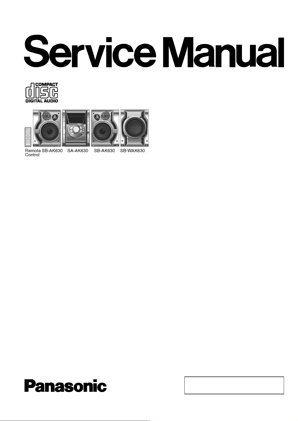
n AMPLIFIER SECTION
RMS output power
THD 10%, both channels driven
1 kHz
(Low channel) 75 W per channel (5 Ω)
10 kHz
(High channel) 70 W per channel (5 Ω)
80 Hz
(Subwoofer channel) 160 W (8 Ω)
Total power output 450 W
For GC only
PMPO 4000 W
n FM/AM TUNER, TERMINALS SECTION
Preset station FM 15 stations
AM 15 stations
Frequency Modulation (FM)
Frequency range
87.50 — 108.00 MHz (50 kHz steps)
Sensitivity 2.5 µV (IHF)
S/N 26 dB 2.2 µV
ntenna terminal(s) 75 Ω (unbalanced)
mplitude Modulation (AM)
Frequency range
For GC only 522 — 1629 kHz (9 kHz steps)
520 — 1630 kHz (10 kHz steps)
For GN only 522 — 1629 kHz (9 kHz steps)
Sensitivity
S/N 20 dB (at 999 kHz) 560 µV/m
© 2005 Matsushita Electric Industrial Co. Ltd.. All
rights reserved. Unauthorized copying and
distribution is a violation of law.
SA-AK630GC
SA-AK630GN
Colour
(S)… Silver Type
udio performance (Amplifier)
Input sensitivity/Input impedance
ux 250 mV,14.7 kΩ
Phone jack
Terminal Stereo, 3.5 mm jack
n CASSETTE DECK SECTION
Track system 4 track, 2 channel
Heads
Record/playback Solid permalloy head
Erasure Double gap ferrite head
Motor DC servo motor
Recording system AC bias 100 kHz
Erasing system AC erase 100 kHz
Tape speed 4.8 cm/s
Overall frequency response (+3 dB, -6 dB at DECK OUT)
NORMAL 35 Hz — 14 kHz
S/N ratio 50 dB (A weighted)
Wow and flutter 0.18 % (WRMS)
Fast forward and rewind time Approx. 120 seconds with
C-60 cassette tape
n DISC SECTION
Discs played [8 cm or 12 cm]
(1) CD-Audio (CD-DA)
(2) CD-R/RW (CD-DA, MP3 formatted disc)
(3) MP3
Bit rate
MP3 32 kbps — 320 kbps
CD Stereo System
Specifications
ORDER NO. MD0501043C3
Sampling frequency
MP3 32 kHz, 44.1 kHz, 48 kHz
CD 44.1 kHz
Decoding 16 bit linear
Digital filter 8fs
D/A converter MASH (1 bit DAC)
Pickup
Wavelength 780 nm
Beam Source Semiconductor laser
udio output (Disc)
Number of channels 2(Stereo)(FL,FR)
n GENERAL
Power Supply
For GC only AC 220-240V, 50/60Hz
For GN only AC 230-240V, 50Hz
Power consumption 260 W
1 Before Repair and Adjustment
4
2 Protection Circuitry
4
3 Prevention of Electro Static Discharge (ESD) to
Electrostatically Sensitive (ES) Devices
5
4 Handling the Lead-free Solder
5
4.1. About lead free solder (PbF)
5
5 Handling Precautions For Traverse Deck
6
6 Precaution of Laser Diode
7
7 Accessories
8
8 Operation Procedures
9
9 Disassembly and Assembly of Main Component
11
9.1. Disassembly flow chart
11
9.2. Gear for servicing (jig) Information
12
9.3. Disassembly of Top Cabinet
13
9.4. Disassembly of CD Lid
13
9.5. Disassembly of Rear Panel
15
9.6. Disassembly of CD Mechanism Unit
15
9.7. Disassembly of Main P.C.B.
16
9.8. Disassembly of Sub-Power P.C.B.
16
9.9. Disassembly of Power P.C.B.
17
9.10. Disassembly of Transformer P.C.B.
18
9.11. Disassembly of Front Panel Unit
19
9.12. Disassembly of Deck Mechanism Unit
19
9.13. CD Mechanism Main Component Replacement
Procedures
20
9.14. Replacement for the pinch roller ass 馳 and head block
34
Power consumption in standby
mode
0.7 W
Dimensions (W x H x D) 250 x 330 x 341 mm
Mass 7.1 kg
Operating temperature range +5 to +35°C
Operating humidity range 5 to 90% RH (no condensation)
n SYSTEM
SC-AK630 (GC) Music center: SA-AK630 (GC)
Speaker: SB-AK630 (GC)
Subwoofer: SB-WAK630 (GC)
SC-AK630 (GN) Music center: SA-AK630 (GN)
Speaker: SB-AK630 (GC)
Subwoofer: SB-WAK630 (GC)
Notes:
1. Specifications are subject to change without notice. Mass and
dimensions are approximate.
2. Total harmonic distortion is measured by the digital spectrum
analyzer.
9.15. Replacement for the Deck motor ass 馳, capstan belt A,
capstan belt B and winding belt
35
9.16. Replacement for the cassette lid ass 馳
38
9.17. Rectification for tape jam problem
39
10 Checking for major P.C.Bs
40
10.1. Checking of Main P.C.B.
40
10.2. Checking of Transformer P.C.B.
41
10.3. Checking of Panel, Deck & Deck Mechanism P.C.B.
42
10.4. Checking of Power P.C.B.
43
11 Self-Diagnostic Function
44
11.1. Self-diagnostic display
44
11.2. How to enter the Self-Diagnostic Function
44
11.3. Cassette Mechanism Test (For error code H01, H02, H03,
F01)
44
11.4. CD Mechanism Test (F15, F26, F16, F17, F27, F28, F29,
F30, H15 & H16)
44
11.5. To clear all Error code
45
11.6. To exit from Self-Diagnostic function
45
11.7. Power Amplifier Failure (F61)
45
11.8. Description of Error Code
45
12 CD Test Mode Function
47
12.1. How to set CD test mode
47
12.2. CD Automatically Adjustment result indication
47
12.3. CD Mecha Aging Test Mode (CR20)
47
12.4. Micon ROM Checksum and Version Display Mode
48
13 Measurements and Adjustments
49
13.1. Cassette Deck Section
49
CONTENTS
Page Page
2
SA-AK63 0GC / SA-AK63 0GN

13.2. Tuner Section 49
13.3. Alignment Points
50
14 Block Diagram
51
15 Voltage Measurement
59
16 Schematic Diagram
61
16.1. (A) CD Servo Circuit
62
16.2. (B) Main (Tuner) Circuit
64
16.3. (B) Main Circuit
65
16.4. (C) Panel Circuit
70
16.5. (D) Transformer Circuit
72
16.6. (E) CD Detect Circuit, (F) Spindle Position Circuit, (G) CD
Loading Circuit & (L) Sub-Power Circuit
73
16.7. (H) Power Circuit
74
16.8. (I) Deck Circuit & (J) Deck Mechanism Circuit
75
17 Printed Circuit Board
77
17.1. (A) CD Servo P.C.B.
77
17.2. (B) Main P.C.B.
78
17.3. (C) Panel P.C.B.
80
17.4. (D) Transformer P.C.B.
82
17.5. (E) CD Detect P.C.B., (F) Spindle Position P.C.B., (G) CD
Loading P.C.B. & (K) Tuner Pack P.C.B.
83
17.6. (H) Power P.C.B. & (L) Sub-Power P.C.B.
84
17.7. (I) Deck P.C.B. & (J) Deck Mechanism P.C.B.
86
18 Wiring Connection Diagram
87
19 Illustration of IC 痴, Transistors and Diodes
88
20 Terminal Function of IC 痴
89
20.1. IC7002 (MN6627953HB) Servo processor/ Digital signal
processor/ Digital filter/ D/A converter
89
20.2. IC7003 (AN8739SBTE2) Focus coil/ Tracking coil/
Traverse motor/ Spindle motor drive
89
20.3. IC2801 (C2CBJG000561) System Microprocessor
90
21 Troubleshooting Guide
92
22 Parts Location and Replacement Parts List
93
22.1. Deck Mechanism (RAA4502-S)
94
22.2. CD Loading Mechanism (RD-DAC026-S)
97
22.3. Cabinet
100
22.4. Electrical Parts List
102
22.5. Packing Materials & Accessories Parts List
111
22.6. Packaging
112
3
SA-AK63 0GC / SA-AK63 0GN

1 Before Repair and Adjustment
Disconnect AC power, discharge Power Supply Capacitors C5820 and C5840 through a 10Ω, 5W resistor to ground.
DO NOT SHORT-CIRCUIT DIRECTLY (with a screwdriver blade, for instance), as this may destroy solid state devices.
After repairs are completed, restore power gradually using a variac, to avoid overcurrent.
For GC only
Current consumption at AC 220-240V, 50/60 Hz in NO SIGNAL mode (volume min at CD mode) should be ~350mA.
For GN only
Current consumption at AC 230-240V, 50 Hz in NO SIGNAL mode (volume min at CD mode) should be ~350mA.
2 Protection Circuitry
The protection circuitry may have operated if either of the following conditions are noticed:
·
No sound is heard when the power is turned on.
·
Sound stops during a performance.
The function of this circuitry is to prevent circuitry damage if, for example, the positive and negative speaker connection wires are
“shorted”, or if speaker systems with an impedance less than the indicated rated impedance of the amplifier are used.
If this occurs, follow the procedure outlines below:
1. Turn off the power.
2. Determine the cause of the problem and correct it.
3. Turn on the power once again after one minute.
Note :
When the protection circuitry functions, the unit will not operate unless the power is first turned off and then on again.
4
SA-AK63 0GC / SA-AK63 0GN

3 Prevention of Electro Static Discharge (ESD) to
Electrostatically Sensitive (ES) Devices
Some semiconductor (solid state) devices can be damaged easily by electricity. Such components commonly are called
Electrostatica lly Sensitive (ES) Devices. Examples of typical ES devices are integrated circuits and some field- effect transistors and
semiconductor “chip” components. The following techniques should be used to help reduce the incidence of component damage
caused by electro static discharge (ESD).
1. Immediately before handling any semiconductor component or semiconductor-equipped assembly, drain off any ESD on your
body by touching a known earth ground. Alternatively, obtain and wear a commercially available discharging ESD wrist strap,
which should be removed for potential shock reasons prior to applying power to the unit under test.
2. After removing an electrical assembly equipped with ES devices, place the assembly on a conductive surface such as
aluminium foil, to prevent electrostatic charge build up or exposure of the assembly.
3. Use only a grounded-tip soldering iron to solder or unsolder ES devices.
4. Use only an anti-static solder remover device. Some solder removal devices not classified as “anti- static (ESD protected)” can
generate electrical charge to damage ES devices.
5. Do not use freon-propelled chemicals. These can generate electrical charges sufficient to damage ES devices.
6. Do not remove a replacement ES device from its protective package until immediately before you are ready to install it. (Most
replacement ES devices are packaged with leads electrically shorted together by conductive foam, aluminium foil or
comparable conductive material).
7. Immediately before removing the protective material from the leads of a replacement ES device, touch the protective material
to the chassis or circuit assembly into which the device will be installed.
Caution
Be sure no power is applied to the chassis or circuit, and observe all other safety precautions.
8. Minimize body motions when handling unpackaged replacement ES devices. (Otherwise harmless motion such as the brushing
together of your clothes fabric or the lifting of your foot from a carpeted floor can generate static electricity (ESD) sufficient to
damage an ES device).
4 Handling the Lead-free Solder
4.1. About lead free solder (PbF)
Distinction of PbF P.C.B.:
P.C.B.s (manufacture d) using lead free solder will have a PbF stamp on the P.C.B.
Caution:
·
Pb free solder has a higher melting point than standard solder; Typically the melting point is 50 — 70°F (30 — 40°C) higher. Please
use a high temperature soldering iron. In case of soldering iron with temperature control, please set it to 700 ± 20°F (370 ±
10°C).
·
Pb free solder will tend to splash when heated too high (about 1100°F/600°C).
·
W hen soldering or unsoldering, please completely remove all of the solder on the pins or solder area, and be sure to heat the
soldering points with the Pb free solder until it melts enough.
5
SA-AK63 0GC / SA-AK63 0GN
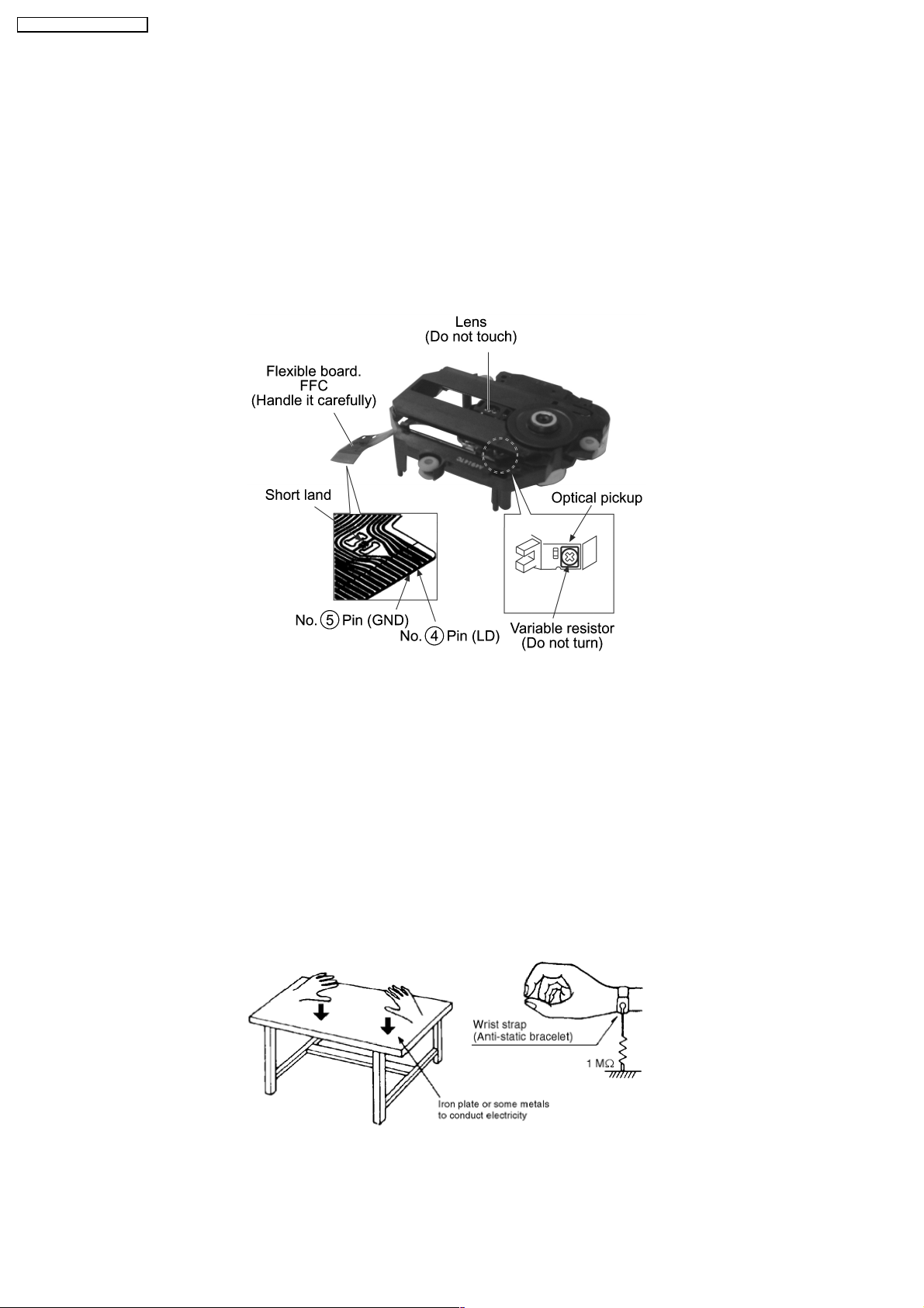
5 Handling Precautions For Traverse Deck
The laser diode in the traverse deck (optical pickup) may break down due to potential difference caused by static electricity of
clothes or human body.
So, be careful of electrostatic breakdown during repair of the traverse deck (optical pickup).
·
Handling of traverse deck (optical pickup)
1. Do not subject the traverse deck (optical pickup) to static electricity as it is extremely sensitive to electrical shock.
2. To prevent the breakdown of the laser diode, an antistatic shorting pin is inserted into the flexible board (FFC board).
3. Take care not to apply excessive stress to the flexible board (FFC board). When removing or connecting the short pin, finish
the job in as short time as possible.
4. Do not turn the variable resistor (laser power adjustment). It has already been adjusted.
Grounding for electrostatic breakdown prevention
1. Human body grounding
Use the anti-static wrist strap to discharge the static electricity from your body.
2. Work table grounding
Put a conductive material (sheet) or steel sheet on the area where the traverse deck (optical pickup) is place, and ground the
sheet.
Caution :
The static electricity of your clothes will not be grounded through the wrist strap. So, take care not to let your clothes touch the
traverse deck (optical pickup).
Caution when replacing the Traverse Deck
The traverse deck has a short point shorted with solder to protect the laser diode against electrostatics breakdown. Be sure to
remove the solder from the short point before making connections.
6
SA-AK63 0GC / SA-AK63 0GN
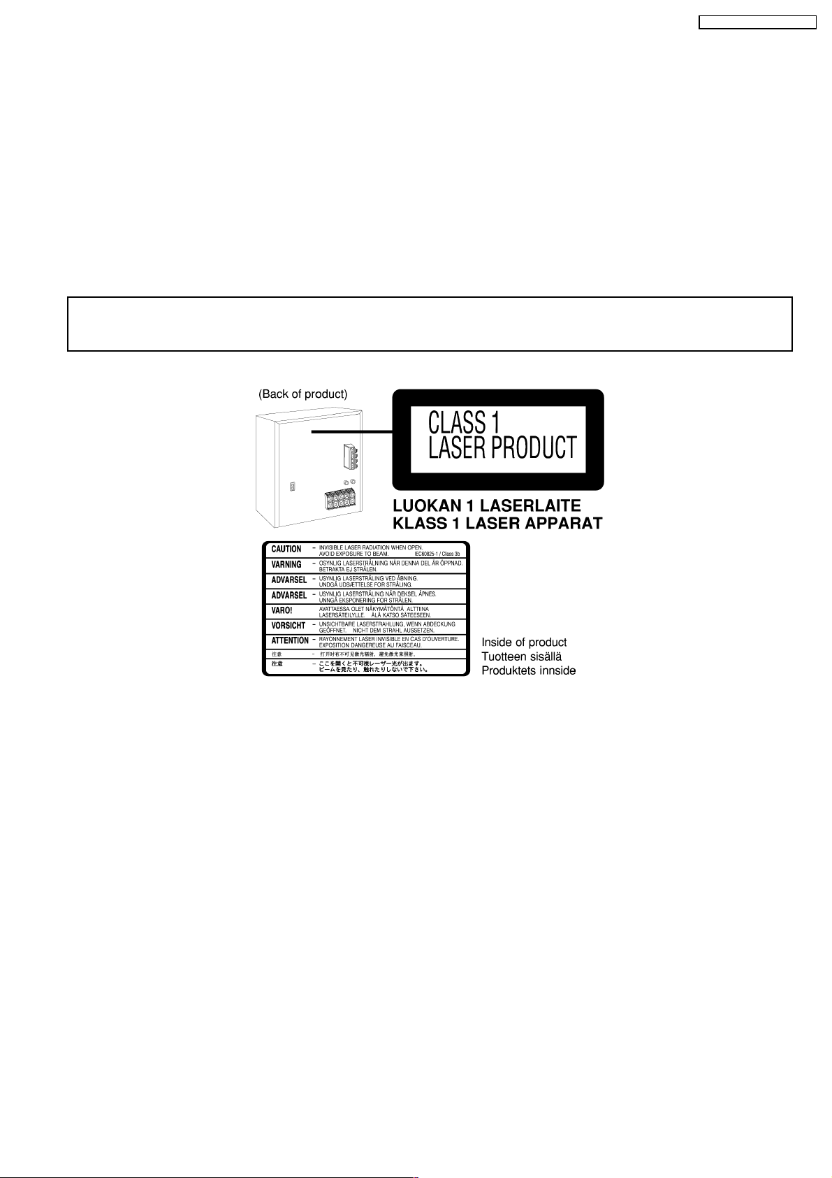
6 Precaution of Laser Diode
Caution :
This product utilizes a laser diode with the unit turned «ON», invisible laser radiation is emitted from the pick up lens.
Wavelength : 780 nm
Maximum output radiation power from pick up : 100 µW/VDE
Laser radiation from pick up unit is safety level, but be sure the followings:
1. Do not disassemble the optical pick up unit, since radiation from exposed laser diode is dangerous.
2. Do not adjust the variable resistor on the pick up unit. It was already adjusted.
3. Do not look at the focus lens using optical instruments.
4. Recommend not to look at pick up lens for a long time.
CAUTION!
THIS PRODUCT UTILIZES A LASER.
USE OF CONTROLS OR ADJUSTMENTS OR PERFORMANCE OF PROCEDURES OTHER THAN THOSE SPECIFIED HEREIN MAY RESULT
IN HAZARDOUS RADIATION EXPOSURE.
n Use of Caution Labels
7
SA-AK63 0GC / SA-AK63 0GN
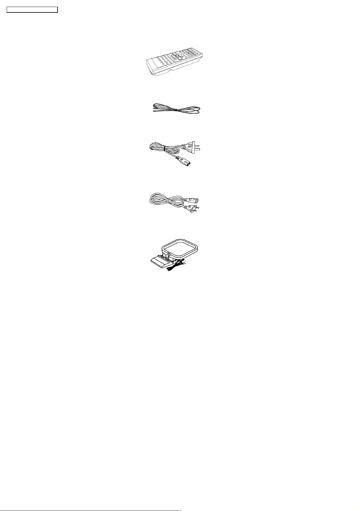
7 Accessories
Remote Control
FM Antenna
AC Cord (For GN only)
AC Cord (For GC only)
AM Loop Antenna
8
SA-AK63 0GC / SA-AK63 0GN
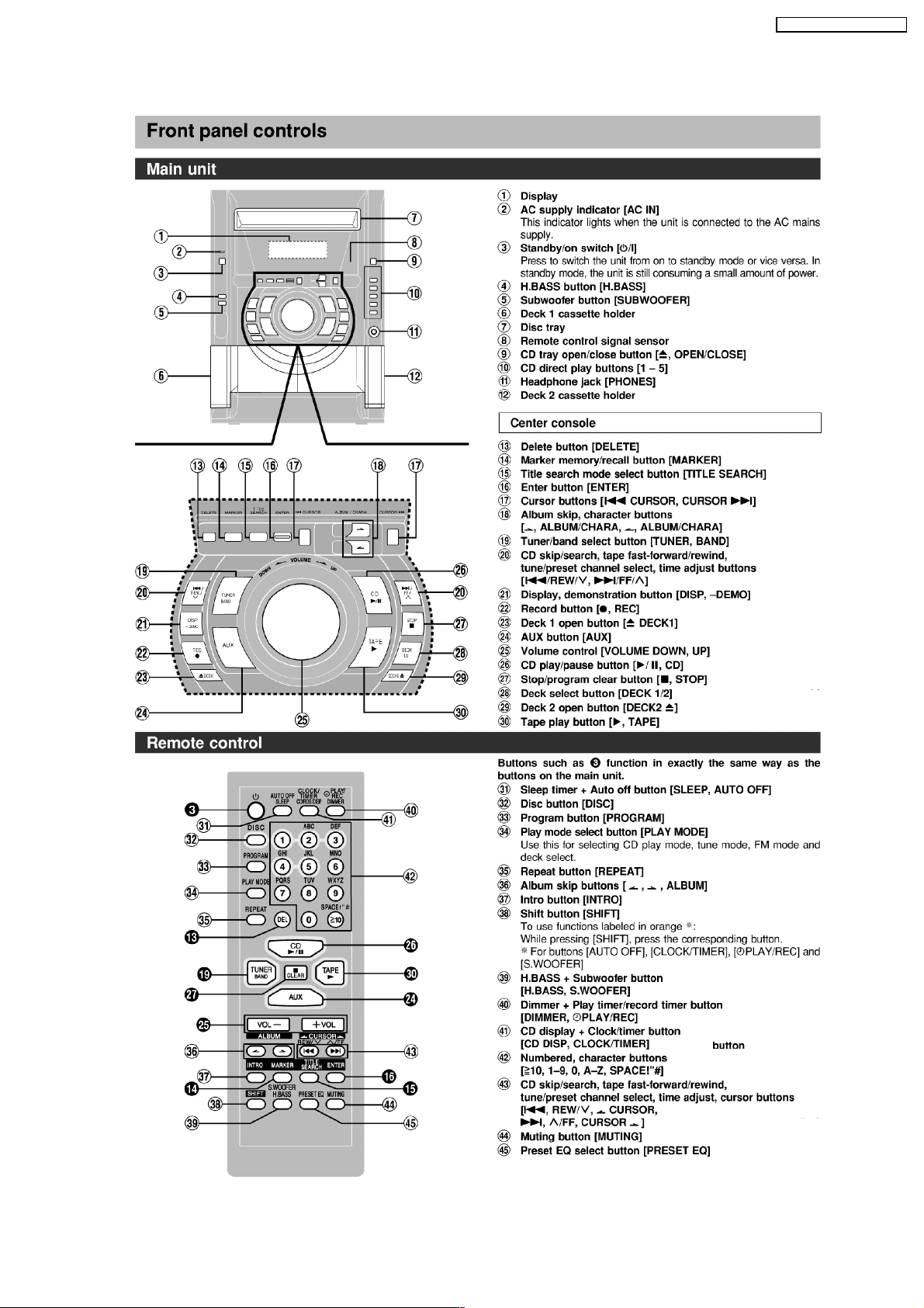
8 Operation Procedures
9
SA-AK63 0GC / SA-AK63 0GN
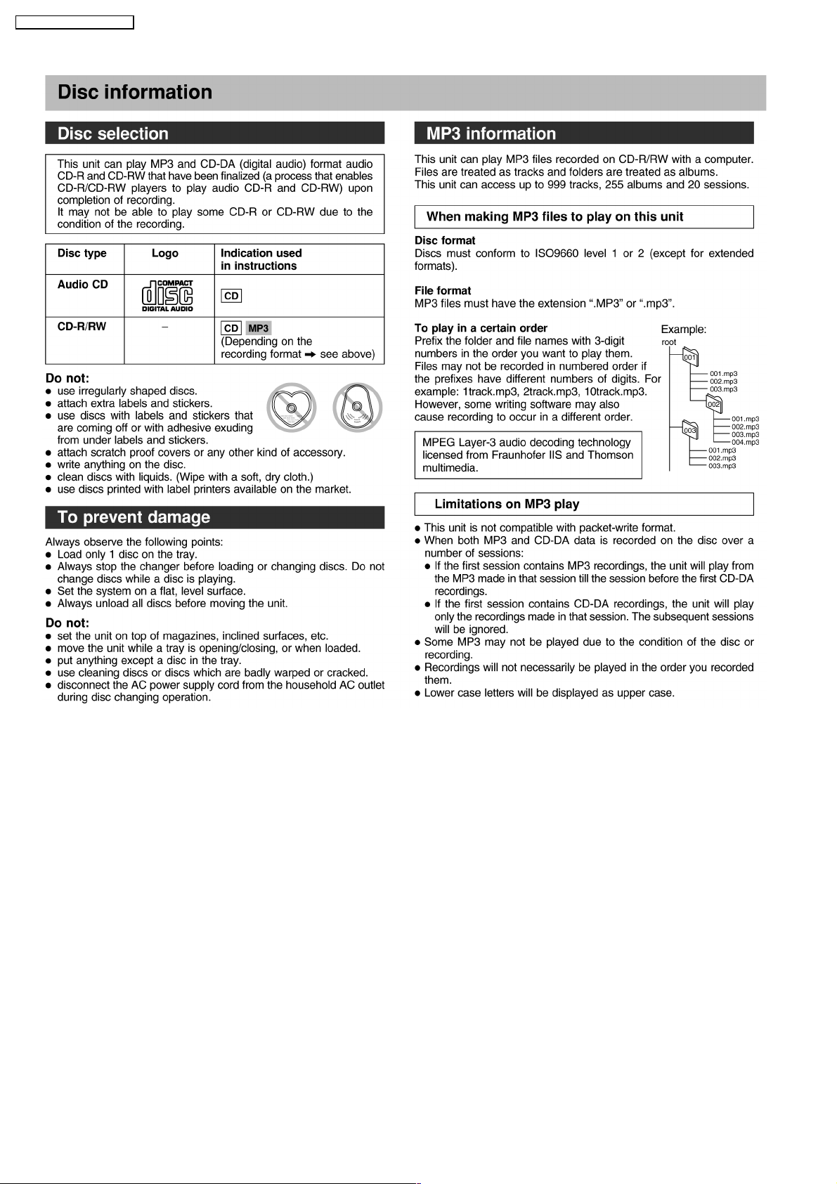
10
SA-AK63 0GC / SA-AK63 0GN
9 Disassembly and Assembly of Main Component
“ATTENTION SERVICER”
Some chassis components may have sharp edges. Be careful when disassemblin g and servicing.
1. This section describes procedures for checking the operation of the major printed circuit boards and replacing the main
components.
2. For reassembly after operation checks or replacement, reverse the respective procedures.
Special reassembly procedures are described only when required.
3. Select items from the following index when checks or replacement are required.
4. Refer to the Parts No. on the page of “Parts Location and Replacement Parts List” (Section 22), if necessary.
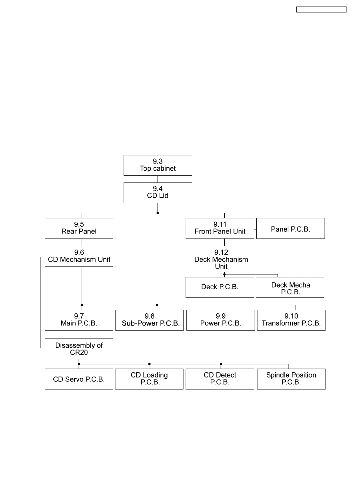
9.1. Disassembly flow chart
The following chart is the procedure for disassemblin g the casing and inside parts for internal inspection when carrying out the
servicing.
To assemble the unit, reverse the steps shown in the chart as below.
11
SA-AK63 0GC / SA-AK63 0GN

9.2. Gear for servicing (jig) Information
1. This unit has a gear which is used for checking items (Open/Close of disc tray, up/down operation of traverse unit by manually)
when servicing.
2. For preparation of gear (for servicing), perform the procedures as follows.
3. In case of re-servicing the same set, the “gear for servicing” may has been taken off because it has been used. The “gear for
servicing” must be stored.
·
Remove the gear provided with mecha cover as shown below.
·
Insert the hexagonal screwdriver (2mm) into the gear, and then project the tip of screwdriver for 1~ 2 mm in length.
12
SA-AK63 0GC / SA-AK63 0GN
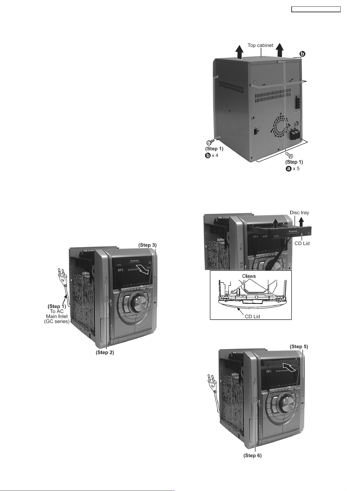
Step 1 Remove 2 screws at each side and 5 screws at rear
panel.
Step 2 Lift up both sides of the top cabinet, push the top
cabinet towards the rear and remove the top cabinet.
·
Opening the disc tray automatically (Using Power
Supply)
Step 1 Connect the AC power cord.
Step 2 Press the POWER button to power up the main unit.
Step 3 Press the OPEN/CLOSE button, the disc tray will open
automatically .
Step 4 Release the 2 claws, and then remove the CD Lid.
Step 5 Press the OPEN/CLOSE button, the disc tray will close.
9.3. Disassembly of Top Cabinet
9.4. Disassembly of CD Lid
(The CD changer unit can be removed after the CD Lid is removed)
·
Follow the (Step 1) — (Step 2) of Item 9.3 — Disassembly of Top Cabinet
13
SA-AK63 0GC / SA-AK63 0GN
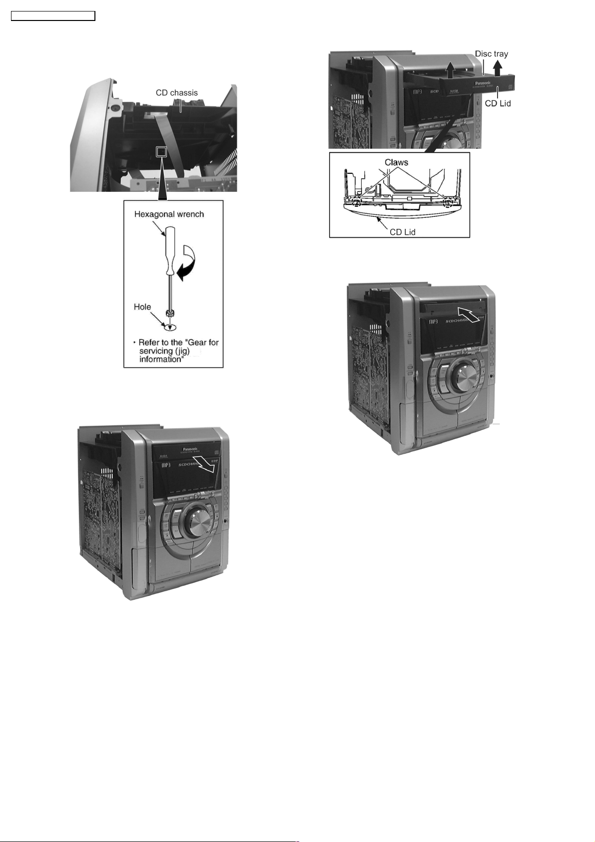
Step 6 Press the POWER button to turn the power off.
·
[Opening the disc tray manually (Using service tools)]
Step 1 Insert the gear tool into the hole on the underside of CD
chassis and then rotate in the direction of arrow. The disc tray
will be opened.
Step 2 Release the 2 claws, and then remove the CD lid cover.
Step 3 Repeat Step 2 but rotate the gear tools in anti- clockwise
direction.
Step 4 The disc tray will be closed.
14
SA-AK63 0GC / SA-AK63 0GN
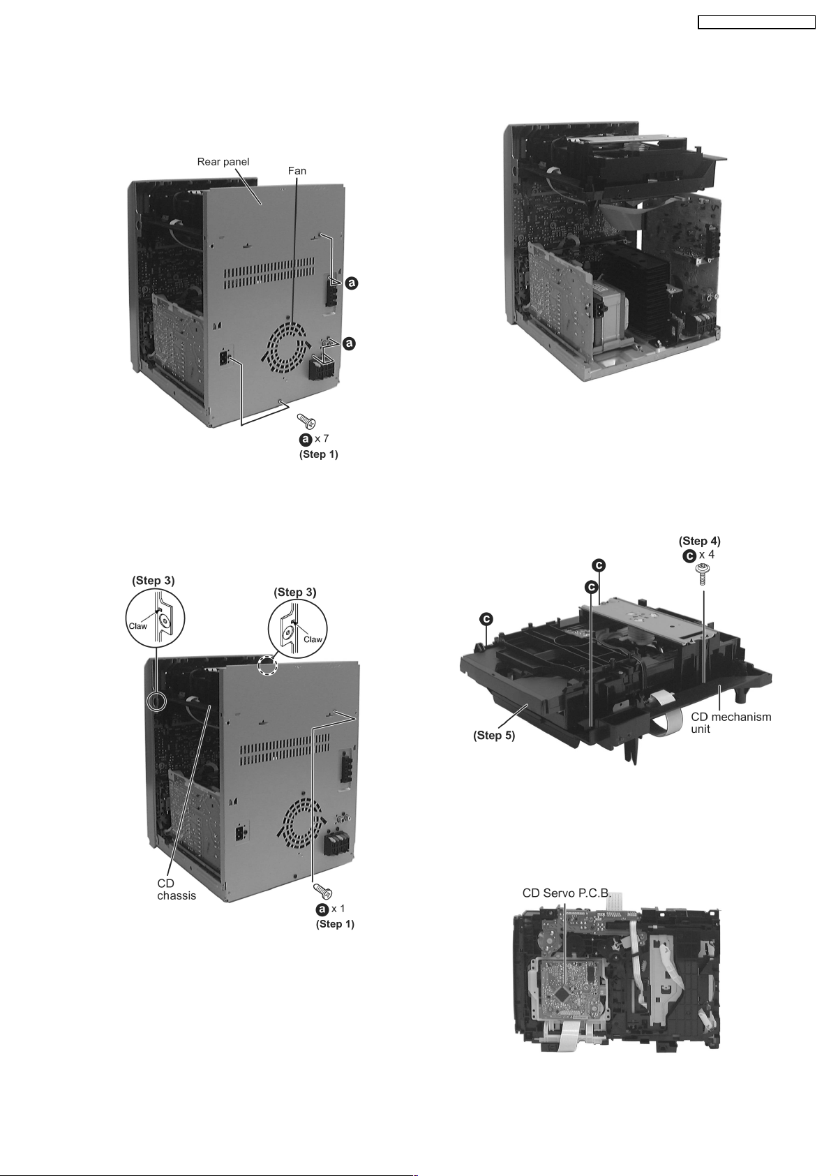
Step 1 Remove 7 screws and disconnect wire CN2810 (Fan) at
rear cabinet as shown.
Step 1 Remove one screw at rear panel.
Step 2 Detach the FFC wires (CN2801 & CN2805).
Step 3 Release the claws of both ends, and then lift up the CD
Mechanism Unit.
Step 4 Remove 4 screws.
Step 5 Remove the CD chassis.
Step 6 Lay the CD mechanism unit as shown.
·
For disassembly of CD mechanism unit, please refer to
Section 9.13 of this manual.
9.5. Disassembly of Rear Panel
·
Follow the (Step 1) — (Step 2) of Item 9.3 — Disassembly of Top Cabinet
9.6. Disassembly of CD Mechanism Unit
·
Follow the (Step 1) — (Step 2) of Item 9.3 — Disassembly of Top Cabinet
15
SA-AK63 0GC / SA-AK63 0GN
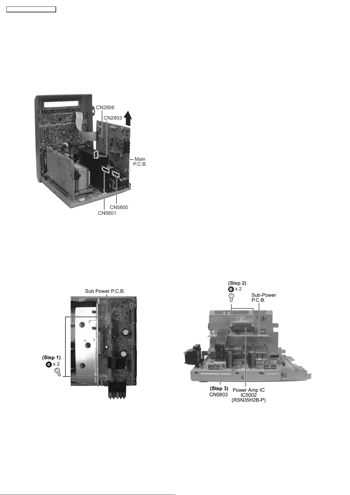
Step 1 Disconnect FFC wires CN2803 & CN2806 from Main
P.C.B.
Step 1 Remove the 2 screws fixed at Sub Power P.C.B..
Step 2 Lift up Main P.C.B. by disconnecting connectors
CN5800 & CN5801 as arrow shown above.
Step 2 Remove 2 screws at Power Amplifier IC.
Step 3 Disconnect connector CN5803
Step 4 Lift up the Sub Power P.C.B. to remove it.
9.7. Disassembly of Main P.C.B.
·
Follow the (Step 1) — (Step 2) of Item 9.3 — Disassembly of Top Cabinet
·
Follow the (Step 1) — (Step 6) of Item 9.4 — Disassembly of CD Lid
·
Follow the (Step 1) of Item 9.5 — Disassembly of Rear Panel
·
Follow the (Step 1) — (Step 3) of Item 9.6 — Disassembly of CD Mechanism Unit
9.8. Disassembly of Sub-Power P.C.B.
·
Follow the (Step 1) — (Step 2) of Item 9.3 — Disassembly of Top Cabinet
·
Follow the (Step 1) — (Step 6) of Item 9.4 — Disassembly of CD Lid
·
Follow the (Step 1) of Item 9.5 — Disassembly of Rear Panel
·
Follow the (Step 1) — (Step 3) of Item 9.6 — Disassembly of CD Mechanism Unit
·
Follow the (Step 1) — (Step 2) of Item 9.7 — Disassembly of Main P.C.B.
16
SA-AK63 0GC / SA-AK63 0GN
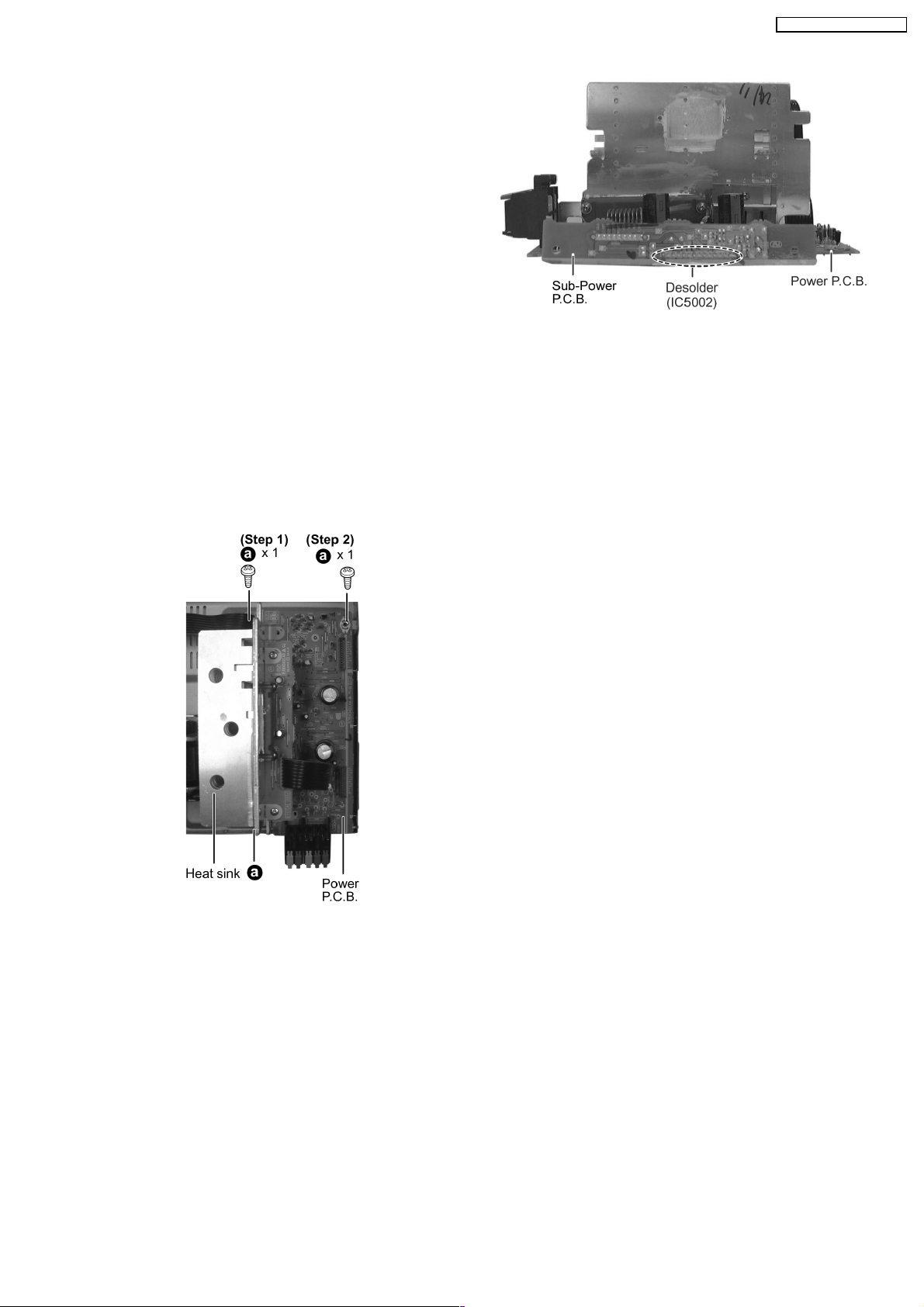
·
Replacement of Power Amplifier IC
Step 1 Desolder the terminals of Power Amplifier IC and
replace the component.
Step 1 Remove the 2 screws fixed at heat sink.
Step 2 Remove 1 screw fixed at Power P.C.B..
Note:
Insulate the Power P.C.B. with insulation material to avoid short
circuit.
9.9. Disassembly of Power P.C.B.
·
Follow the (Step 1) — (Step 2) of Item 9.3 — Disassembly of Top Cabinet
·
Follow the (Step 1) — (Step 6) of Item 9.4 — Disassembly of CD Lid
·
Follow the (Step 1) of Item 9.5 — Disassembly of Rear Panel
·
Follow the (Step 1) — (Step 3) of Item 9.6 — Disassembly of CD Mechanism Unit
·
Follow the (Step 1) — (Step 2) of Item 9.7 — Disassembly of Main P.C.B.
17
SA-AK63 0GC / SA-AK63 0GN
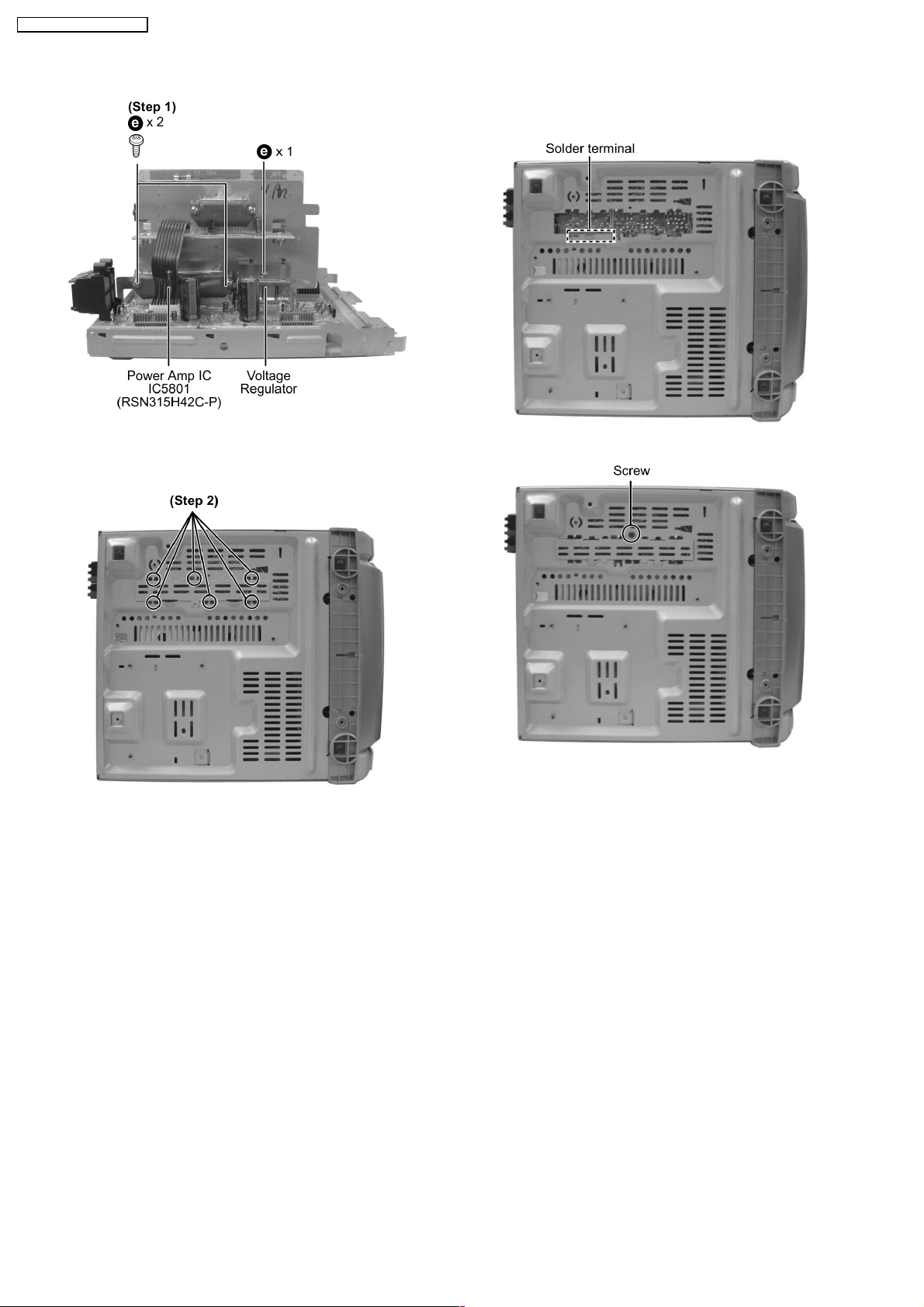
Step 1 Remove 2 screws fixed to the Power Amplifier IC and 1
screw to Voltage Regulator.
Step 2 Break the joint with a metal cutter as shown below.
Step 1 Remove 3 screws, disconnect connector CN5950.
Step 3 Unsolder the terminals of Power Amp IC, transistor and
replace the components.
Step 4 Fix back the cut portion with a screw as shown.
·
Replacement of the Power Amplifier IC/ Voltage Regulator
9.10. Disassembly of Transformer P.C.B.
·
Follow the (Step 1) — (Step 2) of Item 9.3 — Disassembly of Top Cabinet
·
Follow the (Step 1) — (Step 6) of Item 9.4 — Disassembly of CD Lid
·
Follow the (Step 1) of Item 9.5 — Disassembly of Rear Panel
·
Follow the (Step 1) — (Step 3) of Item 9.6 — Disassembly of CD Mechanism Unit
18
SA-AK63 0GC / SA-AK63 0GN

Step 1 Lay the unit as shown below.
Step 2 Release 2 claws at bottom and 2 claws each side, draw
the front panel ass’y forward.
Step 3 Remove volume knob and adaptor.
·
Disassembly of Panel P.C.B.
Step 4 Remove 10 screws.
Step 5 Disconnect connectors (CN2806, CN2803 and
CN5950).
9.11. Disassembly of Front Panel Unit
·
Follow the (Step 1) — (Step 2) of Item 9.3 — Disassembly of Top Cabinet
·
Follow the (Step 1) — (Step 6) of Item 9.4 — Disassembly of CD Lid
·
Follow the (Step 1) — (Step 3) of Item 9.6 — Disassembly of CD Mechanism Unit
9.12. Disassembly of Deck Mechanism Unit
·
Follow the (Step 1) — (Step 2) of Item 9.3 — Disassembly of Top Cabinet
·
Follow the (Step 1) — (Step 6) of Item 9.4 — Disassembly of CD Lid
·
Follow the (Step 1) — (Step 3) of Item 9.6 — Disassembly of CD Mechanism Unit
19
SA-AK63 0GC / SA-AK63 0GN
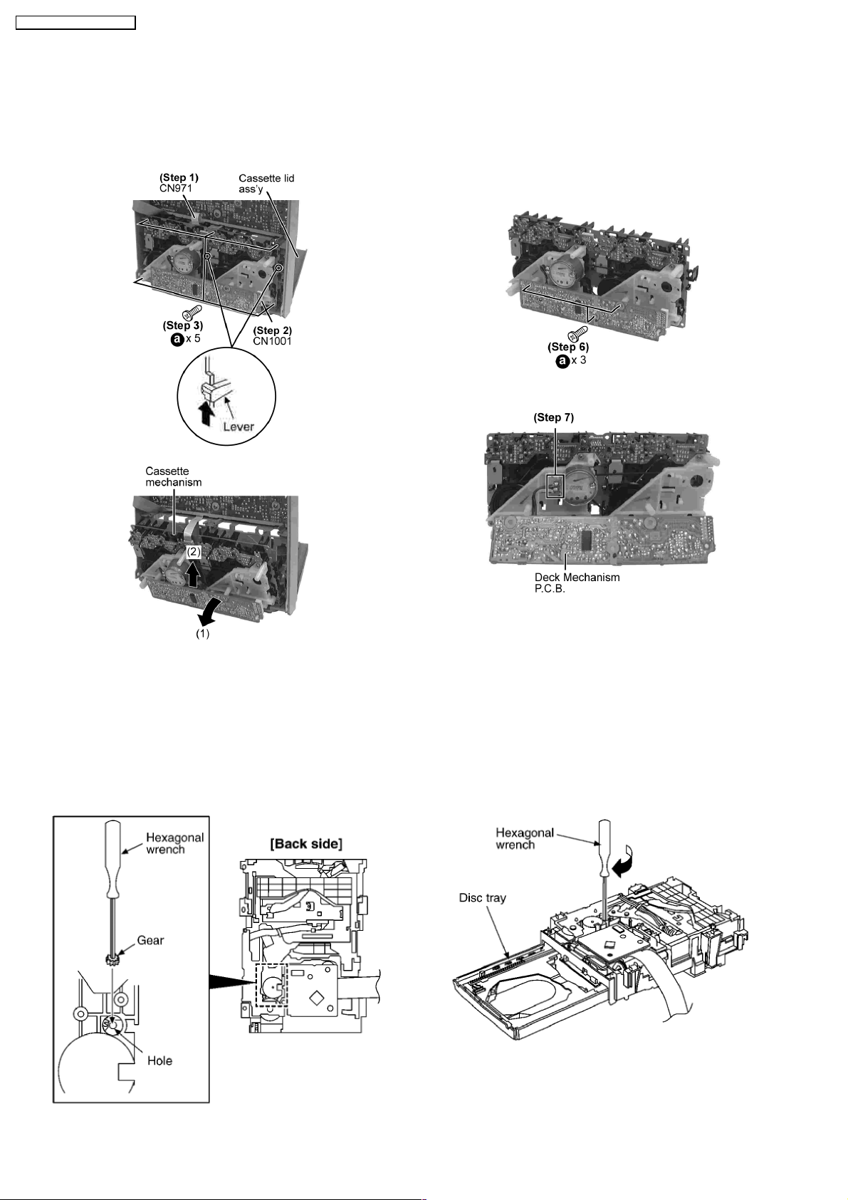
Step 1 Detach FFC wire (CN971).
Step 2 Disconnect FFC flat cable from the connector
(CN1001).
Step 3 Remove the 5 screws.
Step 1 Remove the CD changer unit.
Step 4 Push the lever upward, and then open the cassette lid
ass’y (For DECK1 and DECK2).
Step 5 Tilt the cassette mechanism unit in the direction of
arrow (1), and then remove it in the direction of arrow (2).
·
For replacement of Deck Mechanism P.C.B.
Step 6 Remove 3 screws.
Step 7 Unsolder the motor terminals.
Step 8 Remove Deck Mechanism P.C.B.
Step 2 Insert the gear with hexagonal wrench into the hole.
Step 3 Rotate the hexagonal wrench in the direction of arrow
(clockwise), and then open the disc tray fully.
·
Follow the (Step 1) — (Step 3) of Item 9.11 — Disassembly of Front Panel Unit
9.13. CD Mechanism Main Component Replacement Procedures
·
Follow the (Step 1) — (Step 2) of Item 9.3 — Disassembly of Top Cabinet
·
Follow the (Step 1) — (Step 6) of Item 9.4 — Disassembly of CD Lid
·
Follow the (Step 1) — (Step 6) of Item 9.6 — Disassembly of CD Mechanism Unit
9.13.1. Replaceme nt of the Traverse Deck
20
SA-AK63 0GC / SA-AK63 0GN
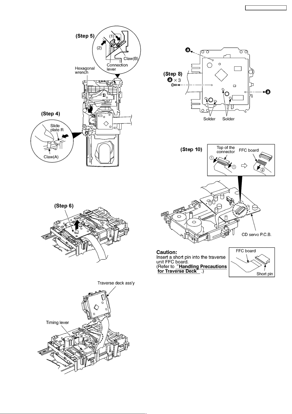
Step 4 With pressing the claw (A), rotate the hexagonal wrench
clockwise. (The slide plate R moves for a little amount.)
Step 5 Pressing the claw (B) in the direction of arrow (1), the
connection lever moves in the direction of arrow (2).
Step 6 Lift up the traverse deck ass’y.
Step 7 Remove the traverse deck ass’y from the timing lever.
Caution:
When removing or inserting the traverse deck avoid touching
the OPU lens and pressing onto the turntable.
Step 8 Remove 3 screws.
Step 9 Unsolder the motor terminals (4 points).
Step 10 Remove the FFC board from the connector, and then
remove the CD Servo P.C.B.
21
SA-AK63 0GC / SA-AK63 0GN
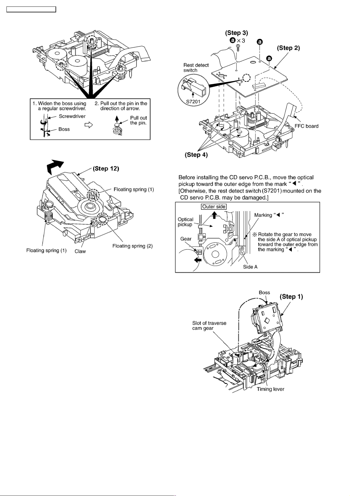
Step 11 Remove the pin.
Step 12 Release the claw, and then remove the traverse deck
ass’y.
Note:
Be careful not to lose the 3 floating spring because those will
also be removed on removal of the traverse deck ass’y.
·
Installation of the CD Servo P.C.B. after replacement
Step 1 Connect the FFC board.
Step 2 Install the CD servo P.C.B. in the traverse deck ass’y.
Step 3 Remove 3 screws.
Step 4 Solder.
·
Note for installation of the CD servo P.C.B.
·
Installation for traverse deck ass’y
Step 1 Install the traverse deck ass’y to the timing lever.
Step 2 Align the boss of traverse deck ass’y with the slot of
traverse cam gear.
22
SA-AK63 0GC / SA-AK63 0GN
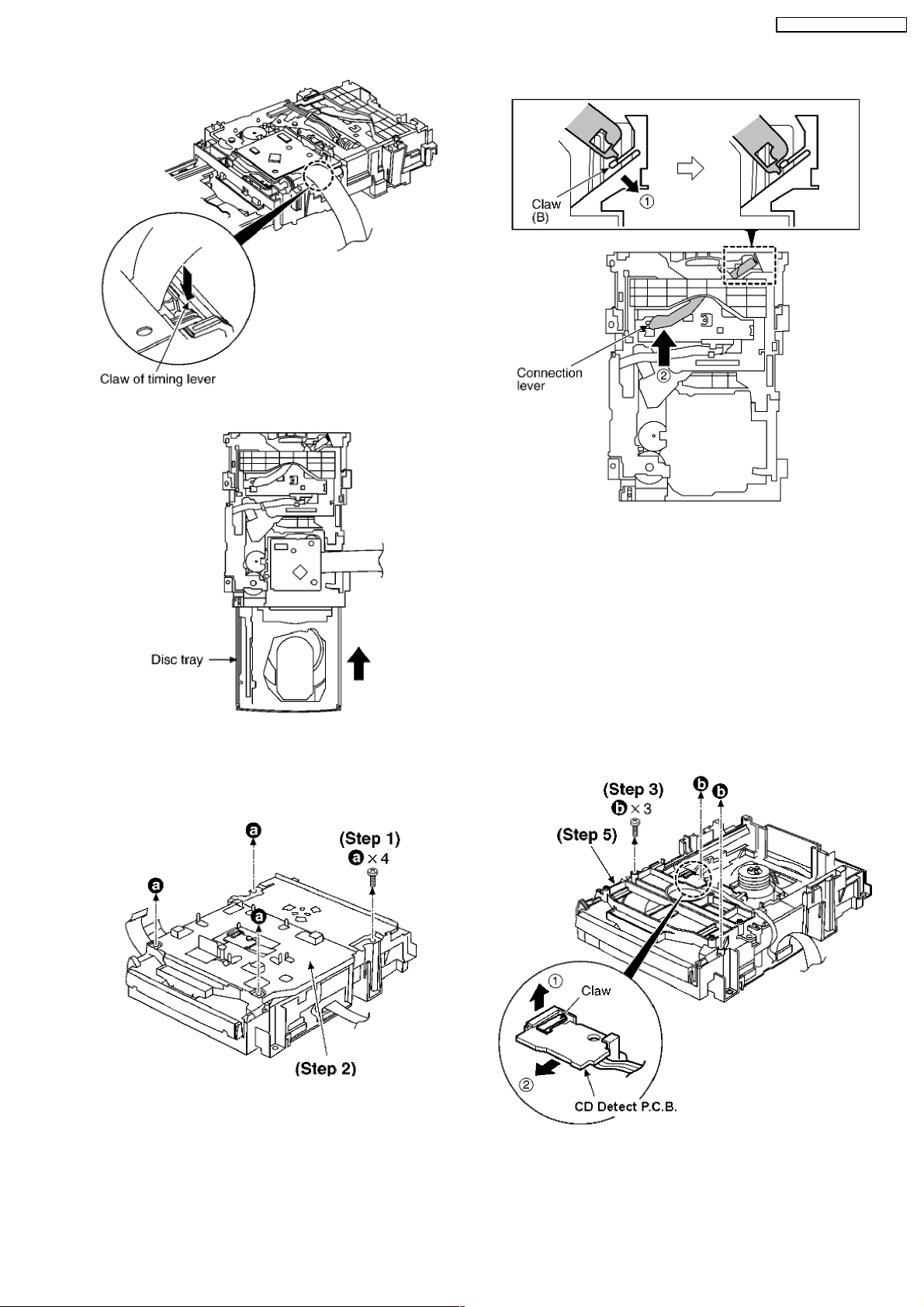
Step 3 Force the claw of timing lever.
Step 1 Remove 4 screws.
Step 2 Remove the upper plate.
Step 3 Remove 3 screws.
Step 4 With lifting the claw in the direction of (1), draw the CD
Detect P.C.B. in the direction of arrow (2).
Step 4 Force the disc tray fully.
Step 5 With pressing the claw (B) in the direction of arrow (1),
force the connection lever in the direction of arrow (2).
Step 5 Remove the mechanism cover.
9.13.2. Replaceme nt for the Disc Tray
23
SA-AK63 0GC / SA-AK63 0GN
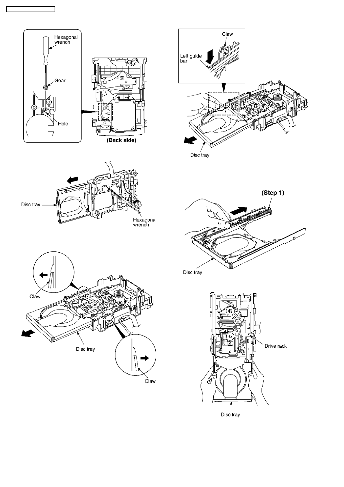
Step 6 Insert the gear with hexagonal wrench into the hole.
Step 7 Rotate the hexagonal wrench in the direction of arrow,
and then open the disc tray fully.
Step 8 Release the both claws, and then draw the disc tray.
Step 9 With forcing the left guide bar manually because the left
guide bar interfers with claw, draw the disc tray.
[Installation of the disc tray after replacement]
Step 1 Slide the drive rack fully in the direction of arrow.
Step 2 Holding the drive rack not to move, install the disc tray.
Step 3 Align the drive rack with the drive gear.
24
SA-AK63 0GC / SA-AK63 0GN
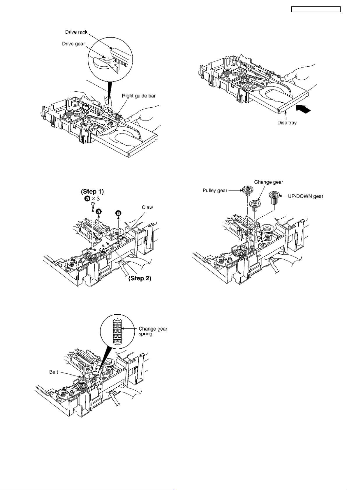
Step 1 Remove 3 screws.
Step 2 Release the claw, and then remove the gear holder.
Step 3 Remove the belt and change gear spring.
NOTE:
Take care not to lose the change gear spring.
Step 4 Remove the pulley gear, change gear and UP/DOWN
gear.
NOTE:
Force the right guide bar of tray base manually not to move
upwards.
Step 4 Holding the disc tray manually, push the disc tray in the
direction of the arrow.
Step 5 Release the 2 claws, and then remove the bottom SW
P.C.B..
9.13.3. Disassemb ly and reassembly for mechanism base drive unit
25
SA-AK63 0GC / SA-AK63 0GN
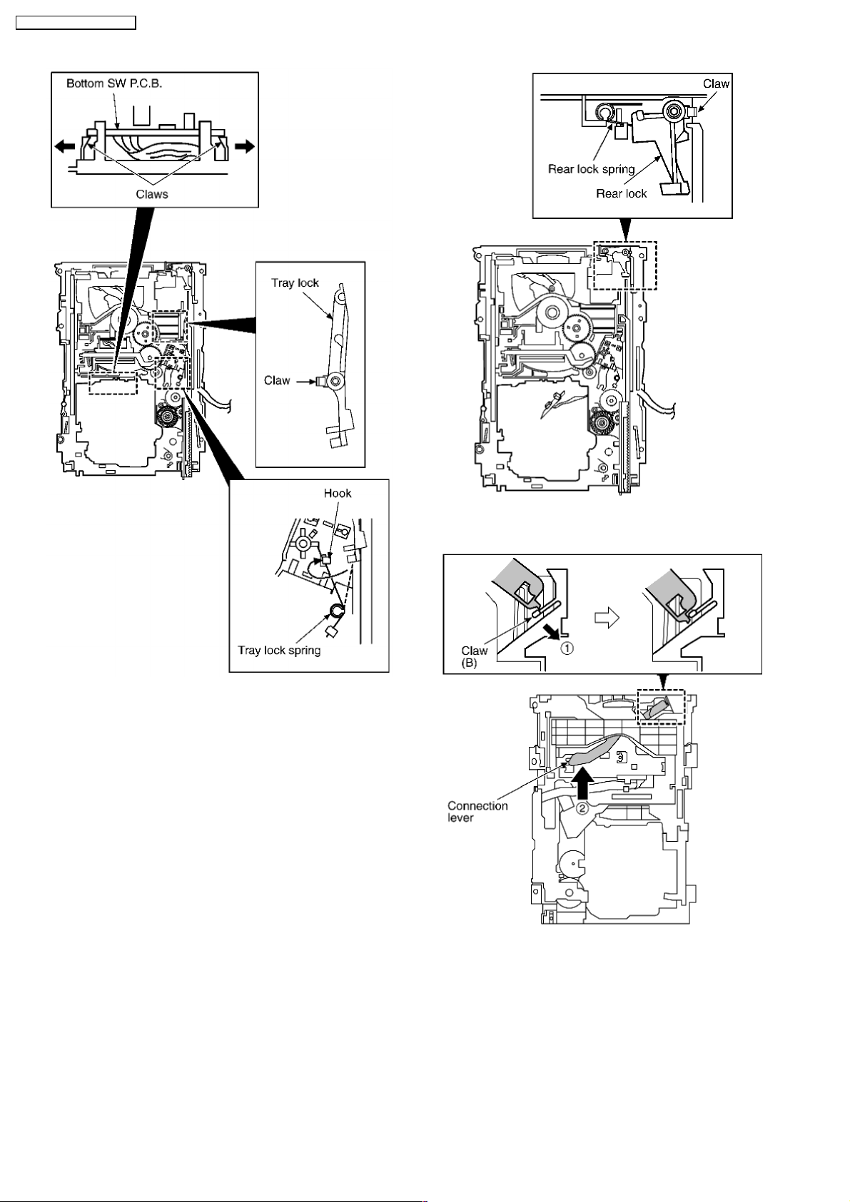
Step 6 Install the tray lock spring to hook temporary.
Step 7 Release the claw, and then remove the tray lock.
Step 8 Release the claw, and then remove the rear lock.
Step 9 Pressing the claw (B) in the direction of arrow (1), force
the connection lever in the direction of arrow (2).
Step 10 Move the slide plate 1 to the end of stock side.
26
SA-AK63 0GC / SA-AK63 0GN
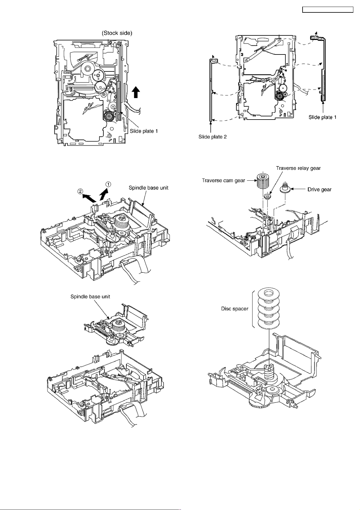
Step 11 Lift up the left end of spindle base unit in the direction
of arrow (1), and then remove the unit in the direction of arrow
(2).
Step 12 Remove slide plate 1 and slide plate 2.
Step 13 Remove the traverse relay gear, traverse cam gear
and drive gear.
[Dissassembly/reassembly for the spindle base unit]
Step 1 Draw the 5 disc spacers.
Step 2 Pushing the claw, slide the support plate in the direction
of arrow, and then remove it.
27
SA-AK63 0GC / SA-AK63 0GN
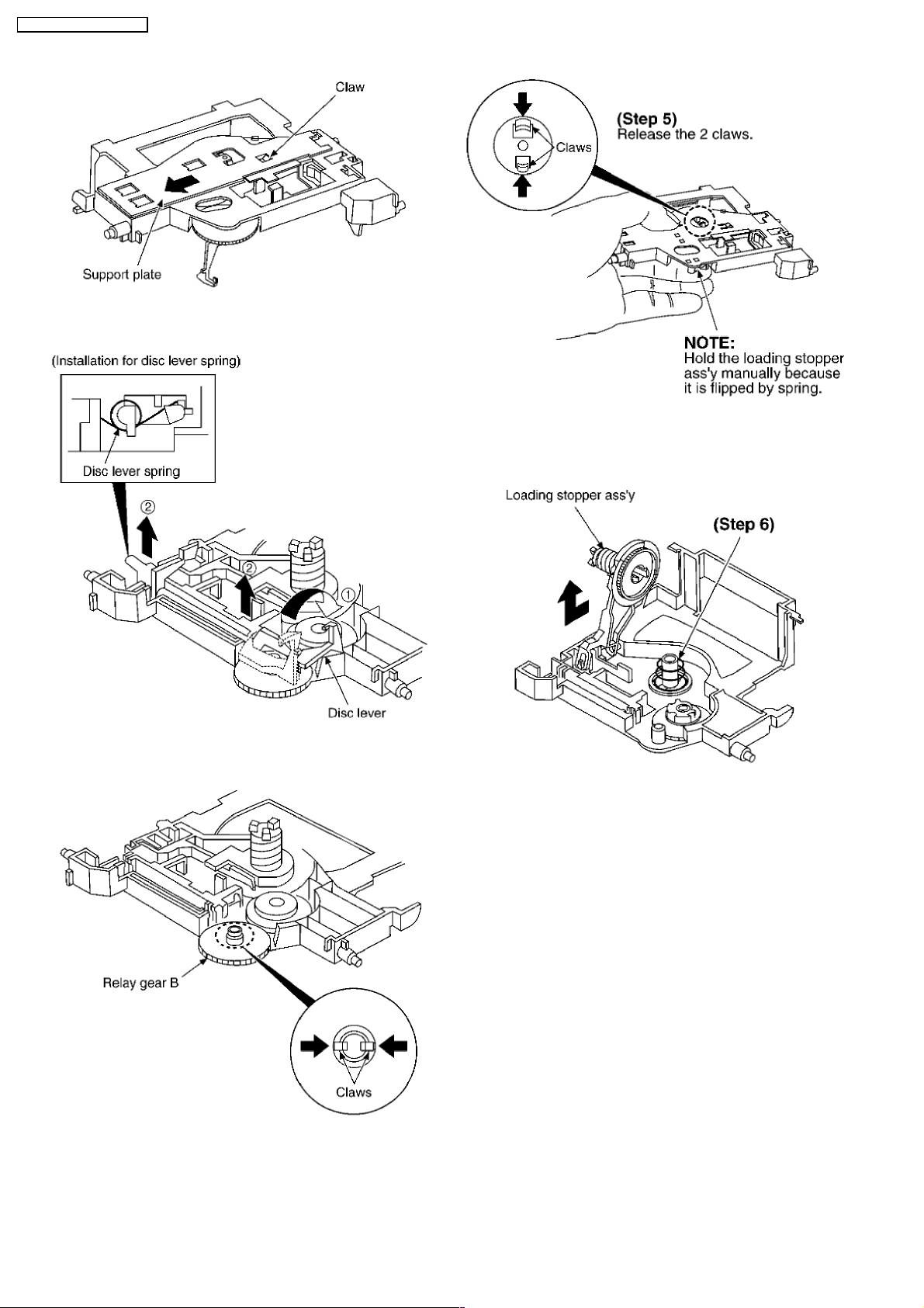
Step 3 Rotate the disc lever in the direction of arrow (1), draw
the disc lever.
NOTE:
Take care not to lose the disc lever spring.
Step 4 Release the 2 claws, and then draw the relay gear B.
Step 5 Release the 2 claws as shown below.
NOTE:
Hold the loading stopper ass’y manually bacause it is flipped by
spring.
Step 6 Remove the cushion spring.
Step 7 Remove the loading stopper ass’y in the direction of
arrow.
28
SA-AK63 0GC / SA-AK63 0GN
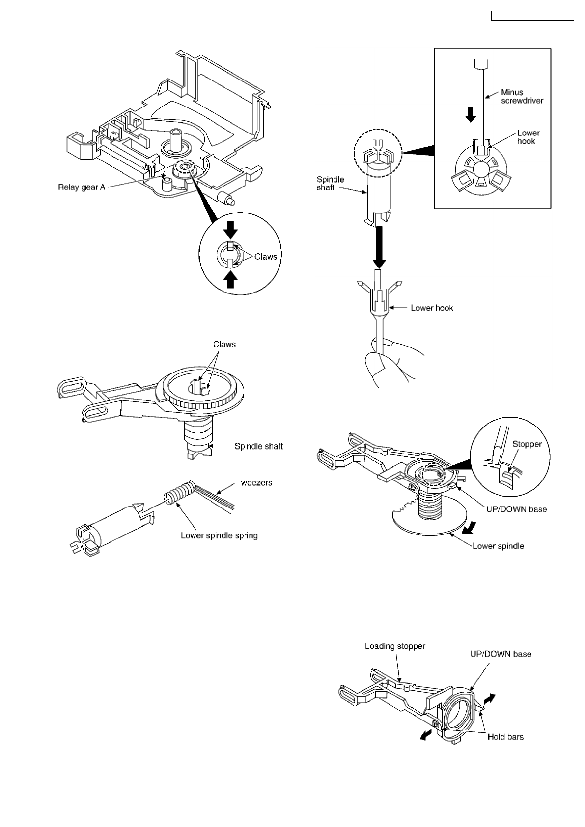
Step 8 Release the 2 claws, and then remove the relay gear A.
Step 9 Release the 2 claws, and then remove the spindle shaft.
Step 10 Remove the lower spindle spring with tweezers.
Step 11 Force the lower hook with thin tip of minus screwdriver.
Step 12 Squeeze the shaft of lower hook, and then draw it.
Step 13 Rotate the lower spindle in the direction of arrow until
the lower spindle interferes with stopper.
Step 14 Insert the thin tip of minus screwdriver between the
lower spindle and UP/DOWN base, and then slacken the lower
spindle to release the stopper. Then, rotate the lower spindle
and remove it.
Step 15 Rotate the UP/DOWN base at a 90° angle. Then,
29
SA-AK63 0GC / SA-AK63 0GN
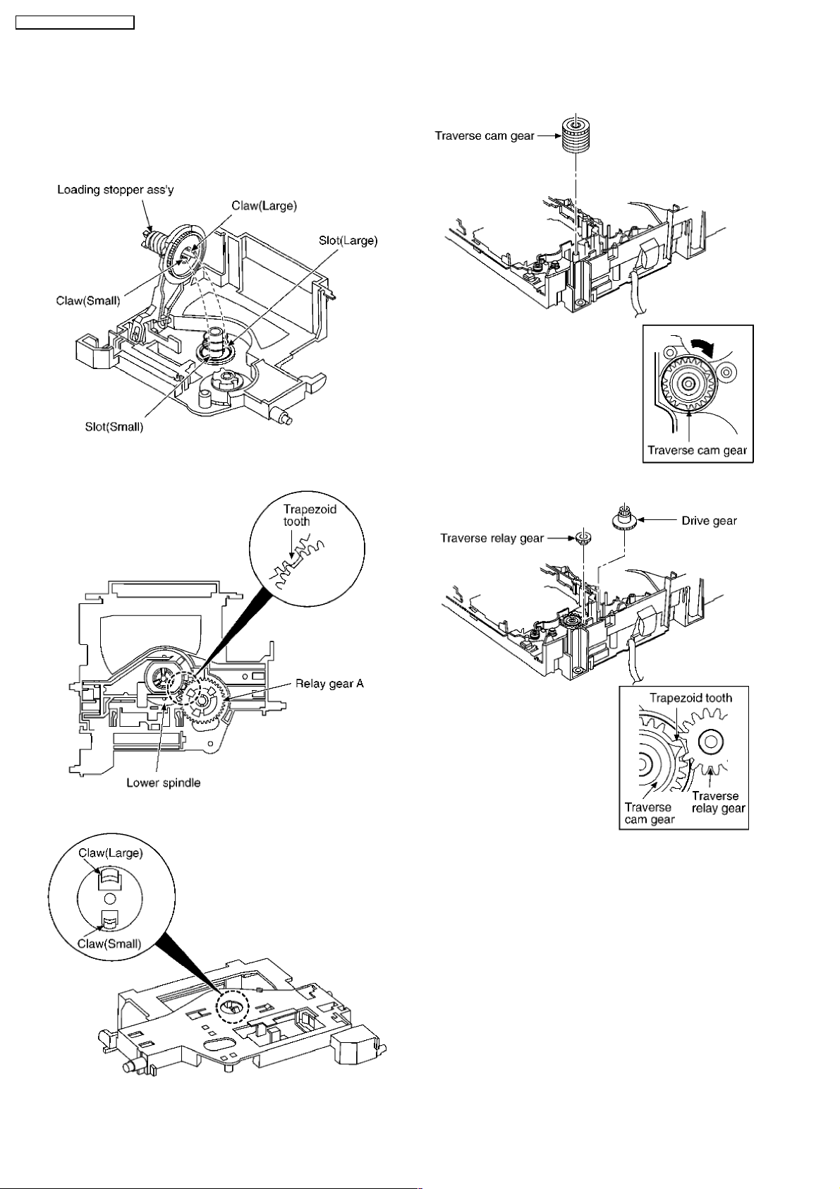
spread the hold bars of loading stopper and remove the
UP/DOWN base.
[Installation for loading stopper ass’y]
Step 1 Align the claw of loading stoppers ass’y with the slot of
spindle base. (Caution should be exercised when alignment of
claw due to the size of claws.)
Step 2 Lower the loading stopper ass’y, and then align the
lower spindle with the trapezoid tooth of relay gear A.
Step 3 Force the loading stopper ass’y, latch the claw firmly.
[Reassembly for mechanism base drive unit]
Step 1 Install the traverse cam gear.
Step 2 Rotate the traverse cam gear to the direction of arrow.
Step 3 Install the drive gear and traverse relay gear.
*When installing the traverse relay gear, align the trapezoid
tooth of gear with tooth of traverse cam gear.
30
SA-AK63 0GC / SA-AK63 0GN

Step 4 Install the slide plate 2 to the mechanism base, and
then match to the connection lever.
Step 5 Install the slide plate 1 to the mechanism base, and
then match to the connection leve and align the trapezoid tooth
of traverse relay gear with the slide plate 1.
Step 6 Install the spindle base unit. (First, slide plate 1.)
Step 7 Move the slide plate 1 to forward fully.
Step 8 Install the rear lock. (The claw should be latched.)
Step 9 Install the Spindle Position P.C.B.. (The claw should be
latched.)
Step 10 Install the tray lock. (The claw should be latched.)
31
SA-AK63 0GC / SA-AK63 0GN

Step 11 Remove the tray lock spring from hook,and then latch
to the tray lock.
Step 12 Install the UP/DOWN gear, change gear, change gear
spring, pulley gear and belt in the order of (1) — (5).
Step 13 Install the gear holder, and then tighten the screw (a).
Step 14 Install the tray base, traverse ass’y, mechanism cover
and upper plate.
[Operation check after servicing]
Check the proper operation of following items with gear and
hexagonal screwdriver.
1. Open/close of tray base.
2. Moving the tray base to the stock side.
3. UP/DOWN operation of spindle base unit.
4. UP/DOWN operation of traverse ass’y.
32
SA-AK63 0GC / SA-AK63 0GN

Step 1 Install the belt temporarily.
NOTE:
Take care not apply the grease to the belt.
Step 2 Upset the CD loading unit.
Step 3 Remove 3 screws.
Step 4 Unsolder the plunger terminals (2 points).
Step 5 Unsolder the motor terminals (2 points).
Step 6 Release the 2 claws (A), and then remove the Motor
P.C.B.
Step 7 Release the claw (B), and then remove the motor ass’y.
[Notice for motor ass’y installation]
1. Locate the name plate of motor to the traverse ass’y.
2. Align the hole of motor with the ribs.
9.13.4. Replaceme nt for the motor ass’y
33
SA-AK63 0GC / SA-AK63 0GN

* The mechanism as shown below is for DECK1. For DECK
2, perform the same procedures.
Step 1 Release the 2 claws, and then remove the pinch roller
(R), (F).
Step 2 Release the 2 claws, and then remove the head
connector.
Step 3 Remove 2 screws.
9.14. Replacement for the pinch roller ass’y and head block
·
Follow the (Step 1) — (Step 2) of Item 9.3 — Disassembly of Top Cabinet
·
Follow the (Step 1) — (Step 6) of Item 9.4 — Disassembly of CD Lid
·
Follow the (Step 1) — (Step 3) of Item 9.6 — Disassembly of CD Mechanism Unit
·
Follow the (Step 1) — (Step 3) of Item 9.11 — Disassembly of Front Panel Unit
·
Follow the (Step 1) — (Step 5) of Item 9.12 — Disassembly of Deck Mechanism Unit
34
SA-AK63 0GC / SA-AK63 0GN
 Loading…
n
AMPLIFIER SECTION
RMS output power
THD 10%, both channels driven
1 kHz
(Low channel)
75 W per channel (5
Ω
)
10 kHz
(High channel)
70 W per channel (5
Ω
)
80 Hz
(Subwoofer channel)
160 W (8
Ω
)
Total power output
450 W
n
FM/AM TUNER, TERMINALS SECTION
Preset station
FM 15 stations
AM 15 stations
Frequency Modulation (FM)
Frequency range
87.50 — 108.00 MHz (50 kHz steps)
Sensitivity
1.8 µV (IHF)
S/N 26 dB
1.5 µV
Antenna terminal(s)
75
Ω
(unbalanced)
Amplitude Modulation (AM)
Frequency range
522 — 1629 kHz (9 kHz steps)
Sensitivity
S/N 20 dB (at 999 kHz)
560 µV/m
Audio performance (Amplifier)
Input sensitivity/Input impedance
Aux
250 mV,14.7 k
Ω
Phone jack
Terminal
Stereo, 3.5 mm jack
©
2005 Matsushita Electric Industrial Co. Ltd.. All
rights
reserved.
Unauthorized
copying
and
distribution is a violation of law.
SA-AK630EE
Colour
(S)… Silver Type
n
CASSETTE DECK SECTION
Track system
4 track, 2 channel
Heads
Record/playback
Solid permalloy head
Erasure
Double gap ferrite head
Motor
DC servo motor
Recording system
AC bias 100 kHz
Erasing system
AC erase 100 kHz
Tape speed
4.8 cm/s
Overall frequency response (+3 dB, -6 dB at DECK OUT)
NORMAL
35 Hz — 14 kHz
S/N ratio
50 dB (A weighted)
Wow and flutter
0.18 % (WRMS)
Fast forward and rewind time
Approx. 120 seconds with
C-60 cassette tape
n
DISC SECTION
Discs played [8 cm or 12 cm]
(1) CD-Audio (CD-DA)
(2) CD-R/RW (CD-DA, MP3 formatted discs)
(3) MP3
Bit rate
MP3
32 kbps — 320 kbps
Sampling frequency
MP3
32 kHz, 44.1 kHz, 48 kHz
CD
44.1 kHz
Decoding
16 bit linear
Digital filter
8 fs
CD Stereo System
Specifications
ORDER NO. MD0503063C3
-
Инструкции по эксплуатации
1

Panasonic SC-AK630 инструкция по эксплуатации
(16 страниц)
- Языки:Русский
-
Тип:
PDF -
Размер:
1.93 MB -
Описание:
Музыкальный центр
Просмотр
На NoDevice можно скачать инструкцию по эксплуатации для Panasonic SC-AK630. Руководство пользователя необходимо для ознакомления с правилами установки и эксплуатации Panasonic SC-AK630. Инструкции по использованию помогут правильно настроить Panasonic SC-AK630, исправить ошибки и выявить неполадки.