
Контроллер Geco G-202-P04 предназничен для управления простыми низкотемпературными и среднетемпературными холодлильными установками, а особенно удобен для использования в холодильных шкафах с дополнотельной подсвечиваемой рекламой выполнен в двухмодульном исполнении. Контроллер имеет два датчика температуры и два релейных выхода к которым можно непосредственно прдключить исполняющие устройства, работающие под напряжением 230В.
Документация
G-202-P04 стабилизирует температуру и управляет процессом автоматического размораживания, параметры которого можно приспособить к специфическим условиям данной окружающей среды. Имеется кнопка для ручного запуска процесса размораживания. Устройство имеет компьютерный интерфейс, при помощи которого можно организовать мониторинг температуры на работающем холодильном оборудовании, а так же процесс автоматизированого программирования системных параметров на этапе продукции ХО. Програмное обеспечение на русском языке.
G202-P04 был запроектирован, как универсальный холодильный контроллер для широкого применения в самых разнообразных холодильных установках: простые торговые холодильные витрины, шкафы, шкафы с двумя независимыми освещениями.
G202-P04 Стабилизирует температуру внутри камеры путем включения и выключения подключенных к контроллеру электрических исполняющих устройств (компрессор, вентилятор, и т. п.) Алгоритм имеет функцию исключающую частое включение и выключение компрессора.
Раз на какое то время устройство автоматически управляет режимом оттайки испарителя. В зависимости от того как ранее была зпрогаммирована функция втотрого реле, пероцесс оттайки будет проходить разными путями. G202-P04 имеет кнопку для ручного включения режима оттайки. Ручное включение режима оттайки значительно облегчает работу холодильной установки в тяжелых, теплых климатических условиях. Имеется главный выключатель. В
режиме „Выключено” все нагрузки обесточены. Имеется кнопка выключения освещения, действующим независимо от главного выключателя. Котроллер индицирует температуру измеренную камерным датчиком. Имеется возможность просмотра температуры испарительного датчика.
В случае аварии камерного датчика температуры, контроллер выводит на дисплей код аварии, и продолжает работу в часовом режиме. В случае аварии испарительного датчика датчика температуры, контроллер выводит на дисплей код аварии. Выключается режим автиматического размораживания, а ручное размораживание реализируется по времени. Имеется компьютерный интерфейс, позволяющий программировать системные параметры, и реализировать мониторинг температуры на работающем оборудовании.
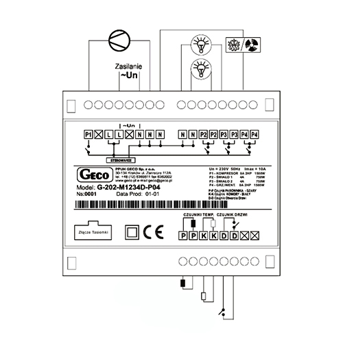
P1– компрессор; P2 – освещение 1; P3 – освещение 2; P4 – тэн/клапан.
|
Geco 20X-P00 Контроллер для холодильных систем три реле, два датчика, цифровой вход. Используется для холодильного оборудования с активным охлаждением (вентилятор испарителя). |
|
|
Geco 201 Контроллер для холодильных систем одно или два реле (зависит от комплектации), два датчика. |
|
|
Geco G-201-P07 Geco G-201-P07 микропроцессорный контроллер, состоящий из двух независимых логических каналов. Каждый из этих каналов можно запрограммировать на управление нагревом либо на управление холодильной установкой. Контроллер может управлять нагревающе- холодильным процессом. В зависимости от конкретного применения к G-201-P07 можно подключать один либо два датчика температуры. Термоконтроллер имеет два выхода к которым можно подключать нагрузку работающую под напряжэением 230 В. G-201-P07 контроллер имеет возможность отдельно для каждого канала программировать функции управления нагрузками, что значительно расширяет спектр его применения. |
|
|
Geco G-202-P00 Geco G-202-P00 контроллер предназничен для управления простыми низкотемпературными и среднетемпературными холодлильными установками, выполнен в двухмодульном исполнении. G-202-P00 стабилизирует температуру и управляет процессом автоматического размораживания, параметры которого можно приспособить к специфическим условиям данной окружающей среды. Имеется кнопка для ручного запуска процесса размораживания. Контроллер имеет два датчика температуры и четыре релейных выхода к которым можно непосредственно подключить исполняющие устройства, работающие под напряжением 230В. |
|
|
Geco G-202-P04 Контроллер Geco G-202-P04 предназничен для управления простыми низкотемпературными и среднетемпературными холодлильными установками, а особенно удобен для использования в холодильных шкафах с дополнотельной подсвечиваемой рекламой выполнен в двухмодульном исполнении. Контроллер имеет два датчика температуры и два релейных выхода к которым можно непосредственно прдключить исполняющие устройства, работающие под напряжением 230В. |
|
|
Geco G-202-P05 Контроллер Geco G-202-P05 предназничен для управления простыми низкотемпературными и среднетемпературными холодлильными установками, выполнен в двухмодульном исполнении. Geco G-202-P05 стабилизирует температуру и управляет процессом автоматического размораживания, параметры которого можно приспособить к специфическим условиям данной окружающей среды. Контроллер имеет два датчика температуры и два релейных выхода к которым можно непосредственно прдключить исполняющие устройства, работающие под напряжением 230В. |
|
|
Geco G-203-P00 Контроллер Geco G-203-P00 предназничен для управления простыми низкотемпературным и среднетемпературными холодлильными установками и камерами, выполнен в двухмодульном исполнении. Контроллер имеет два датчика температуры и два релейных выхода к которым можно непосредственно подключить исполняющие устройства, работающие под напряжением 230В. |
|
|
Geco G-203-P01 Контроллер Geco G-203-P01 предназничен для управления низкотемпературными холодильными установками, выполнен в двухмодульном исполнении. Предназначен для применения в холодильных установках с тэном оттайки размещенном в испарителе – замораживающие установки. Контроллер имеет три датчика температуры и четыре релейных выхода к которым можно непосредственно подключить исполняющие устройства, работающие под напряжением 230В. |
|
|
Geco G-203-P02 Контроллер Geco G-203-P02 контроллер предназничен для управления низкотемпературными и холодлильными установками, c тэном подогрева поддона либо дренажного желоба, выполнен в двухмодульном исполнении. Контроллер имеет три датчика температуры и в зависимости от версии, три, либо четыре релейных выхода к которым можно непосредственно подключить исполняющие устройства, работающие под напряжением 230В. |
|
|
Geco G-203-P07 Контроллер Geco G-203-P07 — микропроцессорный контроллер, состоящий из двух независимых логических каналов. Каждый из этих каналов можно запрограммировать на управление нагревом либо на управление холодильной установкой. Контроллер может управлять нагревающе-холодильным процессом. В зависимости от конкретного применения к G-203-P07 можно подключать один либо два датчика температуры. |
|
|
Geco G-204-P00 Контроллер Geco G-204-P00 предназничен для управления простыми низкотемпературными и среднетемпературными холодлильными установками и камерами, выполнен в одномодульном, щитовом исполнении. Контроллер имеет два датчика температуры и два релейных выхода к которым можно непосредственно подключить исполняющие устройства, работающие под напряжением 230В. |
|
|
Geco G-204-P09 Контроллер Geco G-204-P09 разработан специально для применения в больших конденсаторных системах. Позволяет реализовать охлаждение конденсатора при помощи каскада вентиляторов. Контроллер имеет встроенный термостат температуры масла в поддоне и датчик перегрева поршневой группы компрессора. В зависимости от схемы холодильной установки, можно управлять одним до четырех вентиляторов. |
|
|
Geco G-205-P00 Контроллер Geco G-205-P00 предназничен для управления простыми низкотемпературными и среднетемпературными холодлильными шкафами, выполнен в двухмодульном исполнении. Контроллер имеет два датчика температуры и три релейных выхода к которым можно непосредственно подключить исполняющие устройства, работающие под напряжением 230В. |
|
Инструкция по эксплуатации для контроллеров Geсo представляет из себя ценный материал, позволяющий обеспечить правильное и эффективной функционирование установке. Если Вы впервые столкнулись с установкой и работой данного технического оборудования, инструкция — Ваша настольная книга на ближайшие несколько дней.
Мануал можно скачать бесплатно, без регистраций и прочих не нужных процедур, которые оттягивают момент получения желаемого. Весь материал предоставляется на русском языке. Специалисты пытались максимально просто донести информацию, чтобы потребитель, который никогда не имел дела с данной установкой понял о чем идет речь.
Название
Инструкция
Комментарий

Geco G-20X-P00
Geco G-20X-P00
Контроллер Geco G-20X-P00 для управления простыми низко- и среднетемпературными холодильными установками с активным охлаждением (вентилятор испарителя), выполнен в двухмодульном исполнении. Имеет три реле, два датчика NTC, цифровой вход

Geco G-201
Geco G-201
Контроллер Geco G-201 предназначен для управления простыми низкотемпературными и среднетемпературными холодильными установками. Стабилизирует температуру и управляет процессом автоматического размораживания посредством двух датчиков температуры. Имеется кнопка для ручного запуска процесса размораживания

Geco G-201-P07
Geco G-201-P07
Контроллер Geco G-201-P07 состоящий из двух независимых логических каналов. Каждый из этих каналов можно запрограммировать на управление нагревом, либо на управление холодильной установкой. Контроллер может управлять нагревающе- холодильным процессом. В зависимости от конкретного применения к G-201-P07 можно подключать один либо два датчика температуры. Контроллер имеет два выхода к которым можно подключать нагрузку. Контроллер G-201-P07 имеет возможность отдельно для каждого канала программировать функции управления нагрузками

Geco G-202-P00
Geco G-202-P00
Контроллер Geco G-202-P00 — для управления простыми низко- и среднетемпературными холодильными установками, выполнен в двухмодульном исполнении. G-202-P00 стабилизирует температуру и управляет разморозкой. Контроллер имеет два датчика температуры и четыре реле выхода

Geco G-202-P04
Geco G-202-P04
Контроллер Geco G-202-P04 — для управления низко- и среднетемпературными холодильными установками. Может использован в холодильных шкафах с дополнительной подсвечиваемой рекламой и выполнен в двухмодульном исполнении. Контроллер имеет два датчика температуры и два релейных выхода

Geco G-202-P05
Geco G-202-P05
Контроллер Geco G-202-P05 — для управления простыми низко- и среднетемпературными холодильными установками, выполнен в двухмодульном исполнении. Geco G-202-P05 регулирует температуру и управляет оттайкой. Контроллер имеет два датчика температуры и два релейных выхода

Geco G-203-P00
Geco G-203-P00
Контроллер Geco G-203-P00 — для управления простыми низко- и среднетемпературными холодильным оборудованием, выполнен в двухмодульном исполнении. Контроллер имеет два датчика температуры и управляет компрессором, вентилятором испарителя и оттайкой

Geco G-203-P01
Geco G-203-P01
Контроллер Geco G-203-P01 — для управления низкотемпературными холодильными установками. Контроллер имеет три датчика температуры и четыре релейных выхода

Geco G-203-P02
Geco G-203-P02
Контроллер Geco G-203-P02 — для управления низкотемпературными и холодильными установками, c ТЭНом дренажа. Контроллер имеет три датчика температуры и четыре релейных выхода

Geco G-203-P07
Geco G-203-P07
Контроллер Geco G-203-P07 — состоит из двух независимых логических каналов. Каждый из этих каналов можно запрограммировать на управление нагревом или компрессором.

Geco G-204-P00
Geco G-204-P00
Контроллер Geco G-204-P00 — для управления простыми низко- и среднетемпературными холодильными установками и камерами. Контроллер имеет два датчика температуры и два релейных выхода

Geco G-204-P09
Geco G-204-P09
Контроллер Geco G-204-P09 — реализует охлаждение конденсатора при помощи каскада вентиляторов. Контроллер имеет встроенный термостат температуры масла в поддоне и датчик перегрева поршневой группы компрессора. В зависимости от схемы, можно управлять от одного до четырех вентиляторов

Geco G-205-P00
Geco G-205-P00
Контроллер Geco G-205-P00 — для управления простыми низко- и среднетемпературными холодильными шкафами, выполнен в двухмодульном исполнении. Контроллер имеет два датчика температуры и три релейных выхода

P.P.U.H. „Geco” spółka z o. o.
112A Zarzecze Street, 30-134 Cracow, Poland
tel. +48 (12) 6369811,6361290
fax. +48 (12) 6362002
e-mail: [email protected]
http://www geco.pl
G-202-P00…
G-203-P00…
SELF-CONTAINED CONTROL BLOCK
MAINTENANCE MANUAL (S.C.C.B.)
REFRIGERATION UNITS ORIENTED VERSION
For Programme Version 01
We kindly request that you study this manual carefully PRIOR to connecting and starting up any of
our equipment. Should you have any queries or doubts, please contact us between 8 a.m. and 4
p.m. Any comments e-mailed will be appreciated.
Note !!! The date of the last update is given at the bottom of the consecutive pages, while
information regarding the consecutive changes in the programme version and operation
method are given at the end of page XVI.
Please, use only the most recent version of our manual. You will receive this version free, by post,
after prior order.
Maintenance Manual for Manufacturers,
Page 2
I.
SCCB TYPE G-202
GENERAL CHARACTERISTICS
NOTE: Due to the fact that this manual refers to two similar types of thermostats, the more developed G-202
thermostat will be referred to in further parts of this manual.
The self-contained control block, hereafter called G-202, constitutes a modern, convenient and easyto-use equipment and has been made using microprocessor techniques with the application of automatic
surface assembly process.
Owing to the twin part case and revolutionary technical design, the G-202 can be applied to any
refrigerated counters or refrigeration chambers. The safe voltage operated control panel (5 V) may be
installed in any place, without the necessity of cutting any additional openings or running a number of power
supply cables far away from the equipment being controlled.
The G-202 has been equipped with two temperature sensors, which provides for the capability of
connecting doors opening sensors to the control panel or to the actuating module, which are safe voltage
operated (5 V), as well as four outputs allowing direct connecting of the 230 V operated equipment, with
loading ability as summarized in table 1.
At the special request of the Customer, the G-202 may also be equipped with an additional
evaporator frosting detection system, connected to the thermostat, causing the unit to automatically enter the
defrosting mode.
If the G-202 is used in refrigeration chambers, it stabilizes the temperature, as well as controls
automatic defrosting, the period of which may be adjusted to specific surrounding parameters; it is also
equipped with a pushbutton for activating manual defrosting. As distinct from G-18-2, the G-202 has also
been equipped with lighting system switch over that operates independently of the main circuit breaker
(main isolator).
No special maintenance measures are required for these thermostats; the keyboard has been made
from the special kind of oil, high temperatures resistant as well as resistant to most chemicals. However,
cleaning this oil with sharp objects is not allowed. Instead, use the damp cloth and clean the front panel with
it from time to time.
II.
DENOTATION METHOD AND TECHNICAL DATA
Table 1 - Denotation method for GECO controllers.
Geco
G2
0X
-P
00
K
Denotation
Position:
1
2
3
4
5
6
X
X
-M
XXXX
X
7
8
9
10
11
Nr
Description
Denotation
1
Thermostat.
G
“Geco”
2
Range of operation.
2
3
Case type:
Refrigeration systems.
02-Minipanel; 03- Big keyboard (also
with potentiometer)
0X
Meaning
P
(Keyboard)
5
The beginning of denotation that
refers to the panel configuration
Software version.
00
00 universal, operating like G21
6
Type input user temperature:
K
К- keyboard, P-Potentiometer
7
Equipped with light button
X
L – yes, 0 – not.
8
Sound Beep - buzzer:
X
В – yes, 0 – not
4
PPUH „GECO”, G-202-P00 and G-203-P00 Program version 01 PRINTOUT DATED 2003-03-24
Page3
9
10
Start denotation that refers to the
executive module configuration
Which relays are installed.
M
XXXX Detailed description below.*
D- mechanical or magnetic door sensor;
11 Door open sensor
X
Y – optical door sensor; 0 –no
possibility to connect door sensor;
* Additional information concerning relays denotation
Digits means existence of the relay, 0 – no relay
1 – compressor relay (must exist)
2 – light relay,
3 – fan relay
4 - heater/valve relay
The simplest thermostats are equipped with the following:
• 1000 – compressor
• 1200 - compressor and lighting system
While the mostly developed ones are equipped with the following:
• 1034 - compressor, fan, heater,
• 1234 - compressor, lighting system, fan, heater,
Another examples:
• 1030 - compressor and fan
• 1004 - compressor and heater
• 1230 - compressor, lighting system, and fan
• 1204 - compressor, lighting system and heater
Operating Voltage
Ambient Temperature
Relative humidity
Protection degree
-
230V +10% -15%
+5°C to +40°C
20% to 80%
IP65 on the front side of the control panel
Table 1 – Relays Denotation and Outputs Loads
Output
Load
P1 – compressor
8A
2HP 1500W
P2 – lighting system
4A
750W
P3 – fan
4A
1HP 750W
P4 – heater/valve
8A
1500W
Note !!!
• Currents as specified in the Table are currents consumed by particular
equipment during normal operation and include starting currents of
this equipment !!!
•
III.
The aggregate current consumed simultaneously may not exceed 10A !!!
ORDERING METHOD
The following parameters need to be given in the order, namely:
Page 4
1.
2.
3.
4.
5.
6.
7.
8.
IV.
Maintenance Manual for Manufacturers,
SCCB TYPE G-202
Controller type, e.g. G-20X-P00
Relays to be installed 1 2 3 4
If the terminal in the executive module is to be connected to the door opening sensor – Letter D
after the four digits
If the buzzer is to be installed – Letter B at the end of the description
The length of tape linking the actuating module and keyboard panel
Temperature sensors lengths
Length of the cable leading to the door opening sensor - if it is to be connected to the control
panel (keyboard)
Also, door opening sensors can be ordered, operating fully without contact:
• magnetic sensor with the range of 1 to 2 cm.
• optical sensor with the range 1-2 cm.
DELIVERY, INSTALLATION AND HOOKUP
1. In the appropriate place within the unit cut a hole of 20x30mm in size, however if masking frame of
the panel is not used the size of the hole should be 58x109mm.
2. Mount the actuator on the rail and latch it. For store equipment the SCCB actuator module MUST
be fixed to the floor!!!
3. Any metal elements, through which the G-202 or its cables are run should be ground or protected
otherwise. Fitting G-202 to enable direct action of water on it (e.g. water condensating on the bottom
cover of the shop window), touching the outlet pipe from the evaporator etc. and changing
considerably its temperature in relation to the ambient temperature (e.g. fitting in the immediate
proximity of the compressor and its accessories, cooled and heated elements) is not allowed.
4. Cut the ribbon connecting the panel with the actuator into the desired length plus 2-3cm. Then, after
running it through all penetrations, cut it once more by cutting its ends at right-angle and clip the
plugs on it so that the end of the ribbon be hidden to approx. 0.5mm. The ribbon must be introduced
perpendicular to the plug and clipped so as to make its twisting or non-parallel layout impossible.
Connecting the ribbon to the connectors see figure at the end of the instructions.
5. After fastening the G-202, connect the power cables according to the description provided on the
actuator wall. Depending on the G-202 version some outputs may be not used - on the label with the
description they will not be described and the type symbol in the corresponding places will contain
zeroes - do not connect any conductors to these outputs!!!
6. The applied connectors are certified for continuous load of 16A!!! They incorporate fine thread and
special lamellae, which prevent the wires from being cut, therefore only light tightening ensures
maximum good contact and the use of greater force may lead to stripping out of the thread. In the
result this may lead to the socket melting and short-circuit !!!
7. Any cable surplus should be cut down or winded up and clamped using special plastic bands. The
cables must be firmly secured on its entire length and must not get in contact with the compressor
and its equipment
8. After connecting the unit to the power source there can be voltage across the lighting cable
regardless of switching on or off the unit with the button
therefore the starter or the
fluorescent lamp should be replaced only with the power cord disconnected from the plug!!!
THE SAME APPLIES WHEN CARRYING OUT ANY OTHER REPAIRS !!!
9. If heaters are used, their power must be fitted correctly, which means that during failure of the G-202
or of the external contactor and switching them on for good, there were no possibility of fire or the
device damage.
PPUH „GECO”, G-202-P00 and G-203-P00 Program version 01 PRINTOUT DATED 2003-03-24
Page5
If great power heaters are used then the safety thermostat must be absolutely applied on the
evaporator. This thermostat must operate on the different principle, for instance: mechanical
thermostat.
V.
1.
2.
3.
4.
VI.
THE PRINCIPLE FOR INSTALLATION OF SENSORS, TYPES OF
PROTECTIVE CASES
For each type of the manufactured equipment a place for securing the sensors and the SCCB settings
should be determined experimentally. Absolutely do not change the fastening location nor the way the
sensors are secured nor modify SCCB settings without prior carrying out new tests relating to
temperature stabilization and equipment defrosting cycle !!!
Fastening of the chamber sensor must be done in such a way so that it does not get in contact with food
products and is not exposed to damage when cleaning the equipment. The sensor can be fixed using a
special plastic bracket. This solution causes fast (on/off time delays see VI p. and 6 and 7) response of
the sensor and the entire thermostat to the change in the air temperature in the unit. When desired or
necessary to slow down and "smooth" the time of sensor response to the temperature changes we
recommend to fix it to the metal part of the unit.
Fasten the evaporator sensor in the way to ensure maximum and good contact with the evaporator
lamella and in place where ice remains for the longest time during defrosting. Its fastening should
prevent it from being pushed out by the growing ice. The sensors, wherever possible, should be fixed
vertically so that the cable exits from the bottom of the sensor.
Sensor cables can be shortened or extended in any way, however with respect to the following
rules:
- do not cut the sensor cable at a section smaller than 0.5 m. From the case
- it is not recommended to extend the sensor cable to more than 20 m.
- THE SENSOR CABLES CAN BE CONNECTED TO THE TERMINALS OF THE ACTUATOR
SENSORS IN ANY WAY!!!
(in the same way as you connect the plug to the ~230V outlet)
- for cable extension we recommend using OMY 2x0.5 mm type conductor
- connect the extended cables with great care, by soldering each pair of cores and put thermally
shrinkable jackets on them. Then apply water-proof silicone on the joint and clamp one more
thermally shrinkable jacket on it.
- whiten the ends of the conductors connected to SCCB with tin
OPERATION METHOD
Page 6
Maintenance Manual for Manufacturers,
SCCB TYPE G-202
A - General Information
1. Having turned the equipment on, the three-second starting procedure is activated, during which the
display will show two dashes, for the period of two seconds, and then for the period of one second, the
version of the controller program will be displayed, as well as two to dashes. No activation of the
equipment under control takes place then.
2. Following the completion of the starting procedure, two horizontal dashes signalling the energizing
status will light up on the central segments of the display - if the unit has not been in “on” mode
before!!!. The unit will be activated after pressing the pushbutton
temperature value of the chamber sensor.
. The display will show the
3. Having pressed and held down the pushbutton
for the period of a half second, the display will start
blinking and showing the evaporator temperature, while after the consecutive five seconds, the G-202
will automatically re-enter the chamber temperature readout mode. Note!!! This function is also
activated during the defrosting time, when the display shows the „dF” symbol. The temperature of the
4.
5.
6.
7.
chamber sensor can also be seen by pressing
for 0,5 second, which will make the display show the
chamber temperature (without blinking) to automatically re-enter the displaying of the „dF” symbol
mode after the consecutive five seconds.
The compressor activation is signalled by the small red diode in the right, bottom corner of the display
showing the temperature. This allows easier check of possible damage and mall functions to the system.
If the compressor should have turned on, but the compressor has not been turned on due to the activation
of any of the protection systems (see points 6, 7, 10 and 11), the dot signalling the compressor's
operation will be blinking. When the protection system preset time preset elapses, the daughter will stop
blinking and will be lit permanently, while the compressor will be activated .
The delay in turning the compressor on after its activation temperature is reached (user set
temperature minus bottom value of the hysteresis) is equal to 30 seconds. If the temperature drops again
during this time. The condition of exceeding 30 seconds will be verified again. This is designed to
protect the compressor against unnecessary activation due to e.g. articles placement, droughts, etc.
After every reaching of the preset temperature (user set temperature minus bottom value of the
hysteresis), as well as following any power failure or voltage drops below 175 volts, the G-202 will
make impossible for the compressor to be activated for the period as specified by the ‘c2’ parameter. If,
however, ‘c2’=0min, the protection time will last 60 seconds following any power failure.
pushbutton, the 5-second delay will appear in the
8. Having turned the equipment on using the
compressor activation. This is to cancel the power failure protection from point 7 – this will also pertain
to the time specified by the ‘c2’ parameter, following the compressor’s prior deactivation. This allows
faster compressor operation check.
9. The controller has been equipped with alarm features, providing information regarding sensor’s damage.
Depending on the sensor(s)’ status, the controller performance will be different.
• The mall function to the chamber temperature sensor will make the display show the A1 symbol.
The controller will activate the compressor in the time cycle (clock-based control) in accordance
with times specified in ‘c8’ i ‘c9’ parameters. The defrosting process will function as usual.
• If the evaporator sensor is damaged, the display will show the A2 symbol. The manual and
automatic defrosting is blocked then!!! The only possibility of defrosting the unit is to press the
pushbutton
in order to turn off the unit, and then wait for the ice to thaw.
• If the sensors have been damaged, only the A1 symbol will be displayed.
Having repaired the chamber sensor, the A2 symbol will start to be displayed.
10. If the buzzer has been installed in the controller – see p. II, the buzzer will signal any pressing of any
button. If the controller is turned off (two horizontal dashes on the display are seen then), the buzzer will
signal only if the following pushbuttons are pressed, namely:
and
.
PPUH „GECO”, G-202-P00 and G-203-P00 Program version 01 PRINTOUT DATED 2003-03-24
Page7
11. The lighting system activation and deactivation will take place after pressing the
pushbutton. This
will be signalled by the green LED. If the door opening is reason for lighting system activation, the
green LED will not light up.
The button
will operate independently of the thermostat current switch over -
.
B - Defrosting
1. If the necessity for the additional defrosting occurs, due to difficult operating conditions, press the
pushbutton. This will make the green LED light constantly on the
pushbutton, while the „dF” symbol
will appear on the display, rather than temperature measurement symbol, and this is where the unit will
enter the defrosting cycle.
2. If the defrosting occurs, and the temperature on the evaporator is higher than set in the ‘d2’ parameter,
the unit, after some 10 seconds, will enter the defrosting exiting mode, to resume the operation when the
said mode terminates.
3. If the defrosting occurs, and the temperature on the evaporator is lower than set in the ‘d2’ parameter, the
G-202 will activate the defrosting process, and after reaching the temperature as specified in the ‘d2’
parameter, the unit will enter the defrosting exiting mode (this status is signalled by the green LED,
which blinks on the
pushbutton). The heaters version will then enter the defrosting exiting mode,
comprising two consecutive Phases:
• Thawing Phase – where the compressor and fans are turned off for the period as specified by the‘c3’
parameter;
• Evaporator Freezing Phase – where only the compressor is operated, in order to lower the
temperature of the evaporator to the temperature as specified by the ‘c4’ parameter, prior to
reactivating the fans. The maximal freezing time can not be exceeded, regardless of whether the
evaporator has achieved the temperature of ‘d4’, specified by the ‘c4’ parameter.
4. The procedure of exiting the defrosting mode is terminated with the activation of fans, turning off the
5.
6.
7.
8.
„dF” symbol on the display and turning off the green LED blinking on the pushbutton
.
Should the fans be absent or not connected to the S.C.C.B. system, the unit will act as if they are
installed.
The defrosting process will be terminated following the achieving of the evaporator temperature as preset
in the ‘d2’ parameters, or if the time preset by the ‘c1’ parameter has been exceeded.
Having turned off the „dF” symbol and terminated the defrosting process, the display will show the
temperature as stored right before the defrosting commencement, for the period of time as specified by
the ‘c7’ parameter – this is intended for preventing claims with respect to “violent temperature
fluctuations in the unit”.
The unit performance is the same as in the case of manual and automatic defrosting.
C – The Door Opening Sensor Operation Principle
1. If the door has been opened, the fan will be stopped immediately. In addition to the above, depending on
the ‘r7’ parameter setting, the light may be turned on in the G-202 unit. The display shows the
temperature.
2. If the door has not been closed, after 30 seconds, the “dr” symbol will be constantly lit on the display. If
the buzzer is installed in the controller, the short lasting sound signal will be repeated every 30 seconds.
3. If the door continues to be open after the time as specified in the ‘r8’ parameter, the alarm will be
activated, which will be signalled by the display blinking with “dr” symbol, and with the sound signal if
the buzzer is installed. This is when the compressor will be turned off.
4. If the R8 = 0 the alarm will be activated immediately after opening the door.
5. The alarm may be silenced through pressing any pushbutton. Closing the door deactivates the alarm and
normal operation is resumed.
Page 8
Maintenance Manual for Manufacturers,
SCCB TYPE G-202
6. The controller allows connecting both the door opening mechanical sensor (R6=01), and the mechanical
or magnetic sensor, disconnected in the course of door opening (R6=02).
Hysteresis
When programming the‘d0’ i ‘d1’ parameters (the minimal and maximal user preset temperature) attention
should be paid to the fact that the ‘d3’ hysteresis value causes additional shifting of the temperature to
higher or lower values with relation to the user preset temperature level.
This is particularly significant with regard to the so-called “plus” equipment which should always be
operated at the temperatures above 0oC.
As the Manufacturer of the refrigeration unit (refrigerated counter) (temperatures above 0oC), we require the
unit to allow the operation within the temperature range that does not exceed the values specified below:
Deactivation min: 2ºC. Activation max: 10ºC
Symmetric hysteresis for ‘d3’ even values
Symmetric hysteresis for ‘d3’ odd values
Example No. 1.
The ‘d3’ hysteresis it set at, for example
2ºC
For this hysteresis value, the parameters should
be set as follows: ‘d0’ at 3ºC and‘d1’ at 9ºC
Example No. 2.
The ‘d3’ hysteresis it set at, for example
4ºC
For this hysteresis value, the parameters should
be set as follows: ‘d0’ at 4ºC and ‘d1’ at 8ºC
Example No. 3.
The ‘d3’ hysteresis it set at, for example
3ºC
For this hysteresis value, the parameters should
be set as follows: ‘d0’ at 3ºC and‘d1’ at 8ºC
Example No. 4.
The ‘d3’ hysteresis it set at, for example
5ºC
For this hysteresis value, the parameters should
be set as follows: ‘d0’ at 4ºC and ‘d1’ at 7ºC
Deact. Temp.
½‘d3’
‘d3’
User Preset Temp.
½‘d3’+0.5ºC
‘d3
½‘d3’-
½‘d3’
Activation Temp.
PPUH „GECO”, G-202-P00 and G-203-P00 Program version 01 PRINTOUT DATED 2003-03-24
Page9
VII.
UNIT PARTICULAR COMPONENTS ACTIVATION GRAPHS
A thick line denotes activation, while the dashed one means deactivation of the particular equipment. The
defrosting exiting mode comprises two Phases – see Chapter V p.3.
The “Stop” field denotes deactivation, while the “Operation” field denotes the compressor’s activation
due to exceeding the preset temperature, taking account of the “d3’ preset hysteresis value. The heater on the
figure 1 is intended for heating the tray and/or the water discharge hose from the evaporator. The heater on
figure 4 is intended only for heating the water discharge hose from the evaporator.
ª
IF ERRONEOUS PARAMETERS ARE SET, THE UNIT WILL FAIL TO OPERATE PROPERLY !!!
1. Defrosting through the compressor stop, ‘r1’=01, fans operate only together with the compressor, ‘r2’=00
t= 0
(c3 a n d c4 im m a ter ia l)
CO M PRESSO R
TRAY HEATER
FA N
S to p
O p er a tio n D E F R O S T IN G
D E F R O S T IN G E X IT T IN G
O p er a t.
S to p
2. Defrosting through the heater, ‘r1’=02, fans operate only together with the compressor ‘r2’=00
t= c3
t= c4
CO M PRESO R
HEATER
FA N
S to p
O p er a tio n
D E F R O S T IN G
D E F R O S T IN G E X IT IN G
O p er a tio n S to p
3. Warm vapour defrosting ‘r1’=03, fans operate only together with the compressor ‘r2’=00
t= c3
t= c4
CO M PRESO R
VALVE
FA N
S to p
O p er a tio n
D E F R O S T IN G
D E F R O S T IN G E X IT IN G
O p er a tio n S to p
4. Warm vapour defrosting ‘r1’=03, fans operate permanently after turning on the unit, ‘r2’=01
t= c3
t= c4
CO M PRESO R
VALVE
FA N
S to p
O p er a tio n
D E F R O S T IN G
D E F R O S T IN G E X IT IN G
O p er a tio n S to p
5. Defrosting through the compressor stop ‘r1’=01, fans operate permanently after turning on the unit
‘r2’=01
t= 0
(c3 i c4 b ez z n a cz en ia )
CO M PRESO R
O UTFL. HEA TER
FA N
S to p
O p er a tio n
D E F R O S T IN G
D E F R O S T IN G E X IT IN G
O p er a tio n S to p
6. Defrosting through the heater, ‘r1’=02, fans operate permanently after turning on the unit
‘r2’=01
t= c3
t= c4
CO M PRESO R
HEATER
FA N
S to p
O p er a tio n
D E F R O S T IN G
D E F R O S T IN G E X IT IN G
O p er a tio n S to p
Page 10
Maintenance Manual for Manufacturers,
SCCB TYPE G-202
VIII. SYSTEM PARAMETERS PROGRAMMING
Having activated and checked the unit operation (standard settings are factory set), start entering system
parameters to the G-202 unit.
For this purpose, turn off the unit by pressing the
pushbutton. Then press the buttons
and
,
depress and hold, at the same time press the
pushbutton. All the three pushbuttons need to be
depressed and held for at least the period of 3 seconds. If any of these buttons has been released during the
said time, the unit will abandon the programming mode. When the unit has assumed the programming mode,
the LEDs on the
and
pushbuttons will start to blink, while the display will show the ‘c0’ per one
second. Then, the value of this parameter most recently programmed will be shown. Enter the required
settings, using the
pushbuttons, any longer pushbutton holding time causing the data “fast
rewinding/forwarding”. Then press
, in order to approve the data entered and start entering the next
parameter.
Partial entering of the settings is also possible. If any alteration of the particular setting is not required,
simply press the
pushbutton and the G-202 unit will assume the next parameter setting mode.
Note !!!
The refrigeration unit Manufacturer may block access to a portion of or even to all
parameters available from the keyboard, by means of the computer programming unit. If
this is the case, and the alteration of any of the blocked parameters is attempted, the
display will show the ‘bL’ symbol for the period of 1 second.
Remarks on SCCB programming.
1. IT IS THE RESPONSIBILITY OF THE MANUFACTURER OF THE REFRIGERATING UNIT
AND THE SERVICE ENGINEER TO ENTER NEW SETTINGS REQUIRED FOR NORMAL
FUNCTIONING OF THE UNIT !!!
2. Do the programming carefully, preferably writing down earlier the values of the particular parameters on
a sheet of paper. Remember that any error made when programming some parameters will have very
serious consequences including damage of the product and the refrigerating unit.
3. Having programmed and started the unit check it for proper operation and recheck if the settings of the
system parameters are correct.
4. Transfer of the Service Instructions or any information regarding the mode of programming the SCCB
system parameters to the end user is absolutely not allowed. The end user should receive only and
exclusively a copy of the section IX of these instructions.
PPUH „GECO”, G-202-P00 and G-203-P00 Program version 01 PRINTOUT DATED 2003-03-24
Page11
Table 2: Parameters Denotation
ParaMete
r
Description
Min
c0
Max
Step
Factory
setting
24
1h
6h
99
1min
30min
15
15
25
1min
1min
1min
3min
2min
10min
99
1min
40min
99
1min
10min
The defrosting frequency. Note!!! If this parameter is set to 0
“0”only manual defrosting will be available, while any automatic
defrosting will be unavailable!!! If this parameter is set to”-01”, -01
neither manual nor automatic defrosting will be available!!!
c1 Maximal defrosting time if the evaporator has net reached the 10
preset temperature (d2 parameter) Note!!! If this parameter is set
-01
to „-01” no time limit will be available
c2 Minimal compressor stopping time
0
c3 Evaporator thawing time
0
c4 Evaporator freezing time, after which the fans will start to operate 1
regardless of whether the evaporator has reached the temperature as
set in ‘d5’ setting
c5 Maximal compressor operation time
0
0 – denotes the absence of test
c6 Compressor stopping time following the activation of the
0
protection system as set by the ‘c5’ parameter
c7 Time for which the temperature measured directly prior to the 0
defrosting commencement will be shown after the defrosting
completion (‘c4’ parameter).
c8 Compressor operation time if controlling sensor has been damaged
1
c9 Compressor stopping time if controlling sensor has been damaged
1
60
1min
5min
99
60
1min
1min
25min
5min
d0 User set minimal temperature
-40
20
1°C
1°C
d1 User set maximal temperature
d0+1
40
1°C
10°C
d2 Evaporator temperature at which the defrosting terminates
0
40
1°C
5°C
d3 Hysteresis value
1
10
1°C
2°C
d4 Chamber sensor rescaling with relation to actually measured -10
temperature
10
1°C
0°C
d5 Evaporator temperature at which fans will start their operation after -30
the defrosting process completion.
10
1°C
-5°C
Page 12
Maintenance Manual for Manufacturers,
SCCB TYPE G-202
r1
Evaporator defrosting method, the parameter set as follows:
01 – defrosting through the compressor stop
02 – heater assisted defrosting
03 – warm vapour defrosting (reversed cycle)
01
03
1
02
r2
Evaporator fans operation method, the parameter set as follows:
00 – fans operate only together with the compressor
01 – fans operate permanently after activating the power supply
NOTE!!! This parameter does not affect the cycle and method
of evaporator defrosting
00
01
1
01
r3
Temperature control method, the parameter set as follows:
00 – normal control
01 – the temperature is controlled in accordance with the
evaporator sensor measurements; the programmed temperature
and D0, D1, D2 i D3 parameters pertain to the evaporator
sensor and the chamber sensor measurements are displayed.
00
01
1
00
r5
Defrosting activation conditions during the unit start.
00 – operation commencement without defrosting
01 – if the power failure has occurred during defrosting, the
defrosting process will be activated
02 – defrosting after each power supply activation.
00
02
1
00
r6
Door opening sensor option.
00
00 – no door opening sensor present
01 – door opening sensor available, connected when door is
open
02 – door opening sensor available, disconnected when door is
open
02
1
01
r7
Lighting system activation method
01 – only door sensor assisted lighting system control
02 – only pushbutton assisted lighting system control
03 –door sensor and pushbutton assisted lighting system control
01
03
1
03
r8
Time from the door opening to the alarm activation.
The dr” symbol will be displayed 30 seconds after opening of
the door. If the controller has been equipped with a buzzer, a
short sound signal is emitted, repeated every 30 seconds.
When the time as specified by the R8 parameter has elapsed,
the alarm will be activated and signalled through the dr”
symbol blinking on the display, and, if the buzzer is present in
the controller, the sound signal will be emitted. The compressor
will be stopped.
0 – denotes the immediate alarm activation
0
10
1min
1min
r9
Place where the door opening sensor is installed:
01 – sensor connected to the module accommodating relays
00 – sensor connected to the control module –Note: A special
cable with a plug should be ordered !!!
00
01
1
01
PPUH „GECO”, G-202-P00 and G-203-P00 Program version 01 PRINTOUT DATED 2003-03-24
Page13
IX.
G-202 MAINTENANCE – USER PART
1. Having turned the equipment on, the display will show two dots, for the period of one second, and then
the version of the controller program will be displayed as well as dots for the period of one second.
Following the completion of the starting procedure, two horizontal dashes signaling the energizing
status will light up on the central segments of the display. The unit will be activated after pressing the
pushbutton
. The display will show the temperature value in the device (temperature readings
from the cold room sensor)
2. Setting of the user temperature of the stabilization in the counter.
•
To change settings press the
button. The LED green diode lights on the button and recently
entered value of the temperature is displayed.
•
Buttons:
are used to set the temperature. Each longer holding of the button causes faster
“changes” of the temperature settings.
•
After setting desired temperature one should press the
button again. After that the green LED
diode on the button will light off, and the G-202 will exit the programming mode and start operating
using a new program.
•
If the
button is not pressed the G-202 will automatically exit the programming mode after 5
seconds from the last button press. The temperature value will not be stored in that case.
3. Turning on/off the lighting system.
The lighting system activation and deactivation will take place after pressing the
will be signaled by the green LED diode. The button
current switch
pushbutton. This
operate independently from the thermostat
.
IMPORTANT !!!
. The green LED
If extra defrosting is necessary due to severe operating conditions then press button
will light up on the button, and "dF" will appear on the display instead of the temperature measurement
and the unit will enter the defrosting cycle.
Defrosting will end automatically after the preset time elapses or on reaching the factory preset
temperature.
Carrying out any repairs on one own causes loss of warranty and may bring to en electric
shock and other threat. Therefore all kinds of repairs should be carried out by authorized
and qualified personnel!!!
X.
TROUBLESHOOTING
Page 14
Failure symptoms
1. The display is off
even if G-202 is
connected to the
power supply
Maintenance Manual for Manufacturers,
SCCB TYPE G-202
Check
Check:
- if 220V voltage is present on the power supply terminals L and N
- correct connection of the actuator to the control panel
- remove and reinsert the ribbon sockets
- connect another ribbon
2. The compressor Check:
will not start despite - 220V voltage presence on terminals K and N - If present, then check
its power-on
the compressor
signaling
- if not, then check correct connection of the actuator with the control
- red LED
panel
- connect another ribbon
3. Defrosting heater Check:
does not switch on - if there is voltage 230V on clamps as described on the casing of the
controller
- if there is, check the heater
- if not then check the connection of the executive module with a
control panel
- connect another ribbon
5. Wrong
Check:
temperature
- connections of the sensors to the connectors
indications
- value of the parameter ‘d4’
- correct fastening of the sensor
- condition of the sensor cable – the cable can not show any damages
- carefully the appearance of the external surface of the sensor case
for any signs of mechanical damages.
6. The desired
Check:
temperature cannot value of the parameter ‘d0’ and ‘d1’ (d0<d1)
be set
7. Blinking of dots
Check :
on the display,
- power supply voltage value
cannot be turned
- condition of the power supply connectors
off
- tightening of the power supply connectors
- correct connection of the actuator to the control panel
- connect another ribbon
8. ‘Abnormal’, Check:
PPUH „GECO”, G-202-P00 and G-203-P00 Program version 01 PRINTOUT DATED 2003-03-24
Page15
- if 230V voltage is present on the power supply terminals L and N
- condition of the power supply connectors
- grounding of the refrigerating unit
- condition of the electrical installation and number of the units connected
to one phase
- if you have the type of thermostat (label with output scheme) designed
for your unit
- if the control panel, actuator or the ribbon plugs have been exposed to
water or any other liquid
- if the control panel, actuator or ribbon plugs are exposed to moisture or
rapid temperature fluctuations
- correct connection of the actuator to the control panel
- connect another ribbon
9. Problems
Check:
with defrosting - value of the parameter ‘d2’ and ‘c0’, ‘c1’
the unit
- value of the parameter ‘c1’. This is the maximum unit defrosting time,
whether the evaporator has reached the programmed temperature of the
end of defrosting, or not (parameter ‘d2’). If this time is too short complete
defrosting of the unit will not be possible
- correct fastening of the sensor to the evaporator lamella.
IT MUST BE FIXED SECURELY AND ADHERE CLOSELY TO THE
LAMELLA!!!
- if the evaporator sensor is fixed in place, where the ice remains for the
longest time, if not, check the temperature on the sensor at the moment,
when the last ice lumps fall off the evaporator. THIS IS THE
TEMPERATURE WHICH SHOULD BE ENTERED AS PARAMETER ‘d2’
10. The unit
Check:
does not
- the temperature programmed by the user
reach the
- value of the individual parameters, and in particular 'c2', 'c5', 'd0', 'd1'
preset
- section 9 - Problems with defrosting the unit. If unit defrosting is not
temperature
complete, the unit will not be able to reach the programmed temperature
and does not
!!!
‘refrigerate’
- the way and place of securing the chamber sensor
- if any side panes have been fitted in the rack or sliding panes in the glass
case
- IF THE UNIT IS LEFT IN THE DRAFT OR IN THE SUN !!!
- if there are no fans or air conditioning units installed on the ceiling or
nearby
- if condenser is clean
- temperature in the store (each manufacturer specifies max. working
temperature of the unit)
- gas volume, fans, evaporator heater, hose draining water from the
evaporator
11. Wrong
Check:
operation of
- ‘r6’ and ‘r7’, ‘r9’ parameter value
the door open - sensor connection correctness
sensor
- if the sensor is connected to the actuator then check the connection
between executive module with the control panel
- connect another tape
‘strange’
behavior of
the unit.
Page 16
XI.
Maintenance Manual for Manufacturers,
SCCB TYPE G-202
RETURNS FOR REPAIR
In case of failure and returning SCCB for repair, it is absolutely required to completely
fill in the replacement application form enclosed at the end of this instructions. We
suggest making a Xerox copy of the form rather than cutting it.
PPUH ‘GECO’ reserves the right to refuse a free repair of the unit, if
there is no form, the form is not filled in completely or the seals are
broken !!!
P.P.U.H. ‘Geco’ Sp. z o. o. is not responsible for loses and damages resulting
from provision of information on the method of making changes in the system
data of G-201 by the producer or its service to the final client, incorrect or nonprofessional assembly and for loses caused by defective operation of the
appliance.
PPUH „GECO”, G-202-P00 and G-203-P00 Program version 01 PRINTOUT DATED 2003-03-24
Page17
XII.
SCHEME OF CONNECTIONS. ACTUATOR (EXECUTIVE MODULE) VIEW.
THE METHOD OF CONNECTION OF THE EXECUTIVE MODULE WITH A
CONTROL PANEL USING THE TAPE.
Un = 230V 50Hz
P1 P2 P3 P4 -
COMPRESSOR
LIGHT
FAN
HEATER
Imax = 10A
8A 2HP 1500W
4A
750W
4A 1HP 750W
8A
1500W
90 mm
P-P Evaporator Sensor - Gray
K-K Cold Room Sensor - White
D-D Open Door Sensor
TEMPERATURE SENSORS DOOR SENSOR
Tape Connection
106 mm
T H E D I A G R A M S H O W S TA P E
CONNECTIONS FROM THE INPUT
HOLES VIEW. DIAGRAM SHOWS ALSO
THEIRS PLACEMENT BETWEEN EACH
OTHER, AND ALSO AFTER CORRECT
REALIZATION OF THE CONNECTION.
G 203 CONTROL PANEL FRONT VIEW
G 202 CONTROL PANEL FRONT VIEW
Page 18
Fa ilure:
Maintenance Manual for Manufacturers,
PANEL
SCCB TYPE G-202
AC TUATOR .
V
PPUH „GECO”, G-202-P00 and G-203-P00 Program version 01 PRINTOUT DATED 2003-03-24
Page19
Page 20
Fa ilure:
Maintenance Manual for Manufacturers,
PANEL
SCCB TYPE G-202
AC TUATOR .
V
PPUH „GECO”, G-202-P00 and G-203-P00 Program version 01 PRINTOUT DATED 2003-03-24
G202PLUS GSM 4G Пульт дистанционного управления воротами
информация о продукте
Продукт представляет собой устройство, обеспечивающее многоуровневую авторизацию
для безопасного доступа. Имеет порты для подключения антенн, питания
питания и проводных выключателей. Устройство имеет реле с нормально
Открытый (NO), общий (COM) и нормально закрытый (NC) порты. Он также имеет
сухой контакт, который можно подключить к проводному выключателю. Устройство
поддерживает основные коммуникационные функции для SMS и звонков с помощью
нано-SIM-карта.
Инструкции по использованию продукта
- Авторизация: Авторизовать супер(админа)
Пользователи, отправьте команду «pwd1234» (без кавычек) по SMS. К
авторизуйте обычных пользователей, отправьте команду «pwd0000 1234#TELphone
номер#идентификатор пользователя#» (без кавычек) по SMS. Обратите внимание, что только G203
поддерживает обычных пользователей. - Подключение: Подключите устройство в соответствии с
схема подключения приведена в руководстве пользователя. - Условия эксплуатации: Следуйте предоставленному списку команд
в руководстве по эксплуатации устройства. - Сброс: Чтобы перезагрузить устройство, нажмите кнопку
кнопку сброса на 5 секунд. Это удалит все параметры до
авторизация. Если сброс выполнен успешно, индикатор RUN будет мигать 4
раз быстро, и устройство отключит питание и перезапустится. К
войдите в беззвучный режим, дважды быстро нажмите кнопку сброса. Для сброса
устройство четыре раза быстро, нажмите кнопку сброса четыре раза.
После успешного перезапуска устройство отправит информацию на
суперадминистратора через SMS. - Команды: Используйте список команд, представленный в
руководство пользователя для авторизации пользователей, реле доступа, сохранения реле
вкл/выкл, проверьте состояние реле и проверьте значение сигнала.
1. Инструкция по продукции
Основан на протоколе связи GSM/3G/4G, поддерживает 1001 авторизованного пользователя. Авторизованные пользователи могут удаленно управлять оборудованием, системами и машинами, подключенными к продукту, с помощью SMS-команд и бесплатных звонков. Он широко используется в системах контроля доступа, гаражных воротах, распашных дверях, складных дверях, раздвижных дверях, парковочных системах и оборудовании, которое может быть подключено к релейному управлению, контроллер ворот G202PLUS и контроллер ворот G203 отправят уведомление (через SMS). ) пользователю результата дистанционного управления (например, состояния открытия и закрытия ворот).
С реальной авторизацией и многоуровневой авторизацией, больше безопасности. нет авторизации нет доступа, даже если вы знаете пароль.
2. Физическая компоновка
Порт подключения и освещение
ANT Антенный порт Сигнальная лампочка 1 Регистрация сетевого сигнала: быстро мигает, один раз в секунду
Сигнал 2 Регистрация в сети прошла успешно: быстро мигает, мигает каждые 2 секунды
3 Успешный сброс Быстрое мигание 4 раза Индикатор работы 1 Устройство загружает функцию SMS: горит долго около 2 секунд
Запустите 2 Загрузка и обработка SMS успешно: медленно мигает, мигает каждые 2 секунды
Реле
3Успешный сброс быстрая вспышка 4 раза Свет реле: реле включено освещение реле выключено: выключено Кнопка сброса 1. Нажмите и удерживайте в течение 5 секунд для сброса, он удалит все параметры до авторизации.
успешно, индикатор RUN быстро мигнет 4 раза, затем устройство выключится и перезапустится.
Кнопка сброса
2. Быстро нажмите кнопку сброса 2 раза, индикатор запуска и сигнала перейдет в состояние slient, быстро нажмите кнопку сброса 1 раз, индикатор вернется к нормальной вспышке. После сброса устройства или повторного включения свет также вернется нормальная вспышка.
3. Быстро нажмите 4 раза, чтобы перезагрузить устройство. После успешного перезапуска устройство отправит информацию супер
администратор по смс
DC
+
Вход питания, положительный провод.
— 1 —
9 ~ 36V
–
НЕТ реле
COM-выход
NC
Проводной переключатель
Вход питания, отрицательный провод.
Нормально открытый порт. Реле 3A/240VAC. Подключить к выключателю электрозамка или устройства. Общий порт. Реле 3A/240VAC. Подключить к выключателю электрозамка или устройства. Нормально закрытый порт. Реле 3A/240VAC. Подключение к выключателю электрического замка или устройства. Сухой контакт, который раньше подключался к проводному выключателю, например кнопочному. Примечание: это не должно быть связано с voltagе ввод
3. технические параметры
Номинальный объемtage: DC 9V~36V/1A Рабочая температура: -10+60 Температура хранения: -20+60 Относительная влажность: 10-90%, без конденсации Рабочая частота: GSM: 850/900/1800/1900MHz 3G WCDMA: 900/2100 МГц UMTS 3G CDMA2000:850/1900 МГц UMTS 3G: 850/2100 МГц UMTS 4G: C:GSM:900/1800,LTE-FDD B1/B3/B5/B8 LTE-TDD:B34/B38/B39/B40/B41 E: GSM:900/1800,LTE-FDD B1/B3/B5/B7/B8/B20 SA:GSM:850/900/1800/1900M LTE-FDD B1/B3/B5/B7/B8/B28/B66 Протокол связи: GSM PHASE 2/2+ (включая службу передачи данных) Связанный объемtagВыходное реле: 3A/240V AC SIM-карта типа Nano, 3V Антенна: 50 SMA Проводной переключатель: Поддерживает Размеры: 96.5*50*31.5 мм Вес нетто: 88 г Релейный порт: Контактная емкость 5 Ampс при 250 В переменного тока, Cos=1. 20 Ampс при 14 В постоянного тока
4. Установка
1 Нано-SIM-карта поддерживает базовую функцию связи для SMS и звонков, закрыть блокировку PIN-кода
2 Схема подключения 3 Следуйте списку команд для работы 4 После первой успешной авторизации следуйте списку команд и руководству пользователя для
сделать другие настройки
— 2 —
Схема подключения:
— 3 —
— 4 —
5. Список команд и примечание
Имя команды
Авторизовать супер (администраторов) пользователей
Авторизация обычных пользователей (поддержка G203 только для обычных пользователей)
Звонок для доступа Реле включено Всегда включено реле
Список команд, Все команды не присоединяют «[]»
супер(администратор) pwd1234 обычные пользователи pwd0000
1234#НОМЕР ТЕЛЕФОНА#DEF#
1234#номер телефона#идентификатор пользователя#
1234#Номер телефона NORTEL#DEF#
1234#номер телефона NORTEL#идентификатор пользователя#
1234#ВКЛ# 0000#ВКЛ#
Внимание
Эта команда разрешает новому пользователю быть суперпользователем (администратором) и автоматически назначать идентификатор пользователя, идентификатор пользователя — 001-999 (первым авторизованным пользователем по умолчанию является суперадминистратор). Эта команда разрешает новому пользователю быть суперпользователем (администратором), вам нужно отредактировать идентификатор пользователя самостоятельно (правила идентификатора пользователя: английские буквы, цифры или комбинации, если это чистое число в пределах 3 цифр, это будет идентификатор пользователя.) Эта команда авторизует новый номер телефона, чтобы быть обычным пользователем, и автоматически назначать идентификатор пользователя, диапазон идентификаторов пользователей составляет 001-999. Эта команда разрешает новому пользователю быть обычным пользователем, вам необходимо отредактировать идентификатор пользователя самостоятельно (правила идентификатора пользователя: английский буквы, цифры или комбинации, если это чистое число в пределах 3 цифр, это будет идентификатор пользователя.) При вызове для доступа к устройству устройство автоматически повесит трубку Реле включается по SMS, если есть настройки времени задержки реле, реле по времени следуйте настройке задержки реле.
Кто может использовать команды
Супер (администраторы) пользователи
Супер (администраторы) пользователи
Супер (администраторы) пользователи
Супер (администраторы) пользователи
Все авторизованные пользователи Все авторизованные пользователи
1234#КПОН# 0000#КПОН#
Держите реле включенным, пока не выключите его по SMS или звонку.
Все авторизованные пользователи
Реле выключено
1234#ВЫКЛ# 0000#ВЫКЛ#
Реле выключено
Все авторизованные пользователи
— 5 —
Проверьте состояние реле
1234#РЕЛЕ? 0000#РЕЛЕ?
Проверьте состояние реле включено или выключено
Все авторизованные пользователи
Проверьте значение сигнала
1234#CSQ? 0000#CSQ?
Проверьте значение сигнала
Все авторизованные пользователи
1234#TELID пользователя
Проверьте номер телефона пользователя по идентификатору пользователя
Супер (администраторы) пользователи
Проверить пользователей
1234#QRYTELномер телефона
Проверка пользователей по номеру телефона
Супер (администраторы) пользователи
1234# ТЕЛОЛЛ
Проверить всех пользователей
Супер (администраторы) пользователи
Удалить пользователей
Изменить пароль супер(администратора)
Изменить обычный пароль пользователя (поддерживается только G203)
1234#TEL#идентификатор пользователя#
Удалить пользователей по идентификатору пользователя, пользователя суперадминистратора нельзя удалить
Супер (администраторы) пользователи
1234#DELTEL#номер телефона#
1234#PWDновый пароль#PWDновый пароль#
1234#NORPWDновый пароль #NORPWDновый пароль#
Удалите пользователя по номеру телефона, пользователя суперадминистратора нельзя удалить. Измените правила пароля супер(администратора): количество цифр составляет 4-12 символов, с учетом регистра, поддерживаются буквы и цифры. Измените обычные правила пароля пользователя: число цифр составляет 4–12 символов, с учетом регистра, поддерживаются буквы и цифры.
Супер (администраторы) пользователи
Только супер админ
Только супер админ
Установите время задержки реле G202PLUS
1234#ВРЕМЯ ПОЛУЧИЛОСЬ#
Установите время закрытия реле, реле будет следовать этому времени настройки после закрытия, а затем отключится, время задержки может быть установлено 0-999 с.
Супер (администраторы) пользователи
Установите время задержки реле G203.
1234#ВРЕМЯ ПОЛУЧИЛОСЬ#
Установите время закрытия реле, реле будет следовать этому времени настройки после закрытия, а затем отключится, время задержки может быть установлено 0-9999 с.
Супер (администраторы) пользователи
— 6 —
Проверьте время задержки реле
1234# ПОНЯЛ?
Супер (администраторы) пользователи
Разрешить всем звонкам по телефонным номерам доступ к реле
1234#АА#
Разрешить всем звонкам по номеру телефона доступ к нему
Супер (администраторы) пользователи
Разрешить доступ к нему только авторизованным пользователям
1234#AU#
Супер (администраторы) пользователи
Проверьте, кто может получить доступ к устройству
1234#АС?
добавить push-уведомления для пользователей, только поддержка G203
1234#PUSHномер телефона#
Проверить всех пользователей push-уведомлений
Удалить пользователей push-уведомлений (поддерживается только G203)
1234#PUSHALL 1234#DELPUSH#номер телефона#
Разрешить обратную связь по SMS
1234#Р#
Супер (администраторы) пользователи
Добавьте не более 3 дополнительных пользователей, чтобы получать все отзывы о ретрансляционных действиях (по умолчанию суперадминистратор является пользователем push-уведомлений), остальные 2 пользователя уведомлений не включаются в число 999 пользователей.
Супер (администраторы) пользователи
Супер (администраторы) пользователи
После удаления не будет получать обратную связь о действии реле
Супер (администраторы) пользователи
По умолчанию открыть SMS-отзыв
Супер (администраторы) пользователи
Не разрешать смс-отзывы
1234#Н#
Супер (администраторы) пользователи
Проверьте статус push-уведомлений. Измените свой собственный номер телефона.
Удаленный сброс
Удаленная перезагрузка
1234#М? 1234#MODTEL#новый номер телефона# новый номер телефона#
1234#СБРОС#
1234#ПЕРЕЗАГРУЗКА#
Супер (администраторы) пользователи
Измените свой номер телефона на новый, ваш старый номер телефона потеряет все права доступа после изменения Удалить все настройки, суперадминистратор получит одно SMS, чтобы сообщить об успешном сбросе
Перезагрузите устройство, но
Супер (администраторы) пользователи
Только суперадминистратор
Только суперадминистратор
— 7 —
общая проблема: 1.После авторизации, почему устройство не отвечает на команды или звонки? Из-за разных способов связи операторов в разных странах фактический номер, распознаваемый устройством, может отличаться. Для бывшегоample, ваш авторизованный номер — +86 12345678, а фактический номер приобретения устройства может быть 12345678, что приведет к недействительной авторизации. Если авторизованный номер для отправки инструкции и набора телефонного устройства не соответствует, вы можете использовать этот номер для отправки инструкции по проверке на устройство, чтобы проверить правильность введенного вами авторизованного номера. Инструкции следующие: 0000#CHECKTHEPHONE# Устройство ответит: YOUR Phone Num:XXXXXXXXX для повторной авторизации номера.
— 8 —