
Видео расскажет вам о том, что такое гильотина металл мастер от мастеров СибСталь: Программирование и настройка контроллера ЧПУ Estun E22.
Подробная инструкция по использованию контроллера ЧПУ Estun E22.
Особенности системы ЧПУ ESTUN E22:
Диагностика неисправностей
Управление осями с точностью 0,1 мм
Пошаговое программирование
Автоматический, полуавтоматический и ручной режим работы
Библиотека матриц
Корректировка угла гибки в градусах на каждом шаге программы
Работа в метрической и дюймовой системе
Сохранение в памяти 30 программ по 15 шагов гибки
Наличие библиотеки матриц позволяет производить быструю корректировку угла гибки в градусах на каждом шаге программы.
Это позволяет оператору производить изменение угла гибки без дополнительных вычислений вручную, тем самым снижая риск ошибки оператора.
Компания Metal Master является одним из ведущих производителей и поставщиков металлообрабатывающих станков на рынке РФ.
Станки Metal Master достойно занимают лидирующие позиции во многих сегментах металлообрабатывающего рынка и отвечают критериям: качество, надежность, высокие стандарты..
-
Page 1
E21 Installation Manual (Version: V1.09) -
Page 2: Table Of Contents
E21 Installation Manual Contents Preface ………………….1 Chapter 1 Specification ………………… 3 1.1 Display ………………….3 1.2 Internal memory ………………..3 1.3 Electrical specification ………………3 Chapter 2 Installation ………………..5 2.1 Announcements before installation …………..5 2.2 Installation space and direction …………… 5 2.3 Installation environment ………………
-
Page 3
7.2.2 Equipment grounding design …………….33 7.3 Protective measures ………………34 7.3.1 Measures to ensure electromagnetic compatibility ……….34 7.3.2 Instructions to E21 electromagnetic capability installation ……..36 7.3.3 Install freewheeling diode on relay …………..36 7.4 Demonstration of AC Asynchronies motor wiring ………. 37… -
Page 4: Preface
E21 Installation Manual Preface Target reader This manual guides the following operators to install, configure and maintain the E21 press break numerical control device: Machine tool operators Installation and maintenance personnel Range of application Installation and maintenance personnel can install and operate this device properly by referring to this manual.
-
Page 5
E21 Installation Manual Low temperature; refer to JB-T 8832-2001 General requirements for numerical control device of machine tools, 0 ℃, 2hours. Low temperature store -20℃. Criteria: normal start up, normal operation. High temperature, refer to JB-T 8832-2001 General requirements for numerical control device of machine tools, 40 ℃, 2hours. -
Page 6: Chapter 1 Specification
E21 Installation Manual Chapter 1 Specification 1.1 Display LCD display Dimension of display window: 54.38mm*54.38mm Dot matrix: 160*160 Status light Green indicates running Red indicates stop 1.2 Internal memory Capable of storing 40 programs, each program includes 25 steps at most.
-
Page 7
E21 Installation Manual Storage temperature: -20~55℃ Encoder specification Power supply: DC 12V Incremental encoder: single-ended output, with Z/C phase Output: voltage-type… -
Page 8: Chapter 2 Installation
Therefore, before turning on the power supply, check the connection of input output grounding and power supply wire. Grounding terminal of E21 digital control device must be grounded in correct way, with low impedance lower than 0.3Ω. Do not dismantle the device without authorization so as to avoid malfunction.
-
Page 9: Installation Dimension
E21 Installation Manual 2.4 Installation dimension The installation method is panel mounting. Installation dimension and drawings are shown in Figure 2-1. Unit: mm 4-M4 pressure riveting screws High 8 mm Figure 2-1 Panel Installation Dimension…
-
Page 10: Installation Layout
E21 Installation Manual 2.5 Installation layout 2.5.1 Layout of rear panel Rear panel block diagram is as shown in Figure 2-2, consisting of power port (POWER), input port (INPUT), output port (OUTPUT), encoder port (X, Y), and communication port (COMM).
-
Page 11
E21 Installation Manual Socket number External port name External port description 7 pin. 24VDC, maximum load 10mA, INPUT opto-coupler isolation, maximum withstanding voltage 40V. Incremental encoder is 12V single-ended output, with pulse frequency up to 100KHz. Meanwhile, the port supplies power externally X-ENCODER (as input power of encoder). -
Page 12: Overall Wiring Scheme
E21 Installation Manual 2.5.3 Overall wiring scheme Overall wiring scheme is as shown in Figure 2-3. Figure 2-3 Overall wiring schemes…
-
Page 13: Electrical Wiring Scheme
E21 Installation Manual 2.5.4 Electrical wiring scheme Electrical wiring scheme is as shown in Figure 2-4. 12V single-point 12V single-point incremental encoder incremental encoder Shell Encoder cable Encoder cable grounding shield layer shield layer Y-ENCODER X-ENCODER Shell grounding terminal … ……
-
Page 14: Definition Of Device Interface
E21 Installation Manual 2.6 Definition of device interface 2.6.1 Definition of power interface Definition of terminal is as shown in Table 2-2. Table 2-2 Description of power terminal Terminal No. Signal Description Input terminal of device power, connect to DC +24V.
-
Page 15: Definition Of External Output Interface
E21 Installation Manual Terminal No. Signal Description Y-axis reference point signal, DC +24V signal input, connect Y-EOT to low limit signal of Y-axis block generally. Block touches reference point switch, +24V signal is connected. Count Retain Retain The pump signal must be connected to DC 24V when the MRDY machine is normally running.
-
Page 16: Definition Of Encoder Interface
E21 Installation Manual Terminal No. Signal Description COM2 Common port of system output signal must connect to 0V of I/O power supply. 2.6.4 Definition of encoder interface Encoder interface is DB-9 plug (female), definition of terminal is as shown in Table 2-5.
-
Page 17: Chapter 3 Parameter Description Of Machine Tool
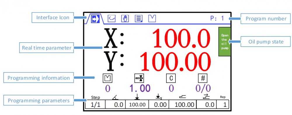
E21 Installation Manual Chapter 3 Parameter Description of Machine Tool 3.1 Enter parameter page Steps to entering parameter page are as below. Step 1 Power on, and press two times to enter Programming Constant page, as shown in Figure 3-1. On this page, program constant can be set.
-
Page 18: Parameter Description
E21 Installation Manual <Note>: You can directly enter Teach Page by input password “1212” and press on Program Constant page. Step 4 Input password 36987 on the CONST page to enter Motor-Speed Detection page, as shown in Figure 3-4. 1.X Motor Dec.
-
Page 19
E21 Installation Manual Name Default value Range Description mm/inch 0 or 1 0: Metric 1: inch 中文/English 0 or 1 0: Chinese 1: English Release Time 0~99.99s Interval between valid yield signal and unloading output when system starts. -
Page 20
E21 Installation Manual Name Default value Range Description X-Enable 0 or 1 0:disable 1:enable Encoder Dir. 0 or 1 0:decreasing 1:increasing Teach. En. 0 or 1 0:disable, enable the orientation function. 1:enable, enable the teaching function. -
Page 21
E21 Installation Manual Name Default value Range Description Repeat Enable 1~99999999 0:disable 1:enable Repeat Time 0~99.99s Interval of back gauge reposition when repeat position Mute Dis. 0~9999.999mm Conversion distance between high speed and low speed. Motor lowers speed when enter this range. -
Page 22
In general, the fixed frequency is 50Hz. [Note] The parameter description of X-axis and Y-axis are the same. If the Vacon transducer is used, the parameter setting for communicating E21 device is as below: E21 Communication Parameter Setting of Vacon P2.1 →… -
Page 23
E21 Installation Manual The parameter description of Motor-Speed Detection is as shown in Table 3-1. Table 3-1 Parameter description of Motor-Speed Detection Name Default Range Description Whether to enable the Motor-Speed Detection function. X-Motor Det. 0 or 1 0: Disabled … -
Page 24
E21 Installation Manual Name Default Range Description X-axis motor begins accelerate from High-speed to the detection end. It will not detect X-axis T3 0~9.99s the motor speed in this setting value. This parameter applies to only the inverter. [Note] The parameter description of X-axis and Y-axis are the same. -
Page 25: Chapter 4 Diagnosis
E21 Installation Manual Chapter 4 Diagnosis When diagnosis is in progress, do not start oil pump. 4.1 Enter diagnosis page This system provides diagnosis tests for input, output, keyboard, FRAM, encoder and LCD, etc. Steps to enter diagnosis page are as follows: Step 1 Power on, the device displays the single-step programming page, Stop Indicator lights.
-
Page 26: Output Diagnosis
E21 Installation Manual 4.3 Output diagnosis When you enter the DIAGNOSE page, select 2. OUT DIAG. to enter OUT DIAG. page, as shown in Figure 4-3. [Operation Guide] Using the Arrow Key to move the cursor to the corresponding port…
-
Page 27: Fram Diagnosis
E21 Installation Manual 4.5 FRAM diagnosis When you enter the DIAGNOSE page, select 4. FRAM DIAG. to enter FARM DIAG. page, as shown in Figure 4-5. , the page displays “Diagnosing”. When the diagnosis is [Operation Guide] Press success, the page will display “The result is: OK”. However, if the page long displays “Diagnosing”, it indicates the memory is failure.
-
Page 28: Lcd Diagnosis
E21 Installation Manual 4.7 LCD diagnosis When you enter the DIAGNOSE page, select 6. LED DIAG. to enter LED DIAG. page, as shown in Figure 4-7. [Operation Guide] Press , the device will star to diagnose the LCD. To stop the diagnosis, press LCD DIAG.
-
Page 29: Chapter 5 Commissioning
If necessary, cut down motor power immediately to avoid accident. 5.1 Preparation before Commissioning Check E21 power line, ground wire, input/output signal wire and encoder plug for reliable and accurate connection. Check whether output voltage of 24V switch power is normal or not.
-
Page 30: Action Commissioning
E21 Installation Manual Over.Dis.: 5.00 Repeat Enable: 1 Repeat Time: 1.00 Stop Dis.: 100 Mute Dis.: 4000 Overrun En.: 0 (Bilateral orientation is enabled) Y-Axis parameter setting Y-axis parameter setting: the method is similar to the setting of X axis parameter 5.2.2 Action commissioning…
-
Page 31: Counting Commissioning
E21 Installation Manual 5.2.4 Counting commissioning Edit multistep program on programming page (setting number of work piece is over 1, single step is excluded), press “Start”, depress pedal to dry running when X, Y axis are in position (note Y axis position and pressure), observe whether counting has increased;…
-
Page 32: Chapter 6 Maintenance
E21 Installation Manual Chapter 6 Maintenance 6.1 Instructions to maintenance In order to use this system safely and properly, follow the instructions. When power is on or system operates normally, do not open cover plate or panel as it may damage the components.
-
Page 33: Periodic Inspection
E21 Installation Manual Inspection item Standard content Standard Treatment specification Connection status Check terminal Screw is not loose Fastening screw for loosening terminal screw. LED display status Check whether LED LED (green) indicate display is correct. system running, LED (red) indicate system stop.
-
Page 34
E21 Installation Manual Inspection item Standard Standard Treatment content specification Install Tension, Mobile module Module must Secure the mobility be installed screw. If securely. CPU and I/O module loses, fasten them by screws. Dust and Visual No dust or Remove and… -
Page 35: Chapter 7 Appendix
7.2.1 Ground classification in equipment cabinet Ground in equipment cabinet is divided into three categories: Signal ground: for example, signal reference in E21 controller; Shield ground: the shield layer of communication cable can prevent the system from external interference and hinder internal noise interfere other equipment. The ground shield layer connected to be called shield ground must connect to protective ground.
-
Page 36: Equipment Grounding Design
RC net. RC network of E21 is integrated inside the product with one end connect to signal ground, and the other end connect to ground (three pins of POWER terminal), as shown in Figure 7-1.
-
Page 37: Protective Measures
7.3 Protective measures 7.3.1 Measures to ensure electromagnetic compatibility E21 and its components are specially designed for industrial environment with strong electromagnetic compatibility. But when install and operate, take possible interference by the outside into account, and improve reliability and stability of the system.
-
Page 38
E21 Installation Manual Coupling mode Cause Typical cases Inductive Changing current flows Transformer; coupling through current loop. Contactor and relay pull-in or disconnect; High frequency signal cable, etc. Radio frequency Space electromagnetic field coupling makes guide line generate induced voltage current. -
Page 39: Instructions To E21 Electromagnetic Capability Installation
E21 Installation Manual 7.3.2 Instructions to E21 electromagnetic capability installation E21 may be installed outside the cabinet. If work environment is poor, keep E21 close to cabinet as much as possible; Metal housing shall connect to protective ground via earth conductor, and ground resistance shall be no higher than 0.3 ohm;…
-
Page 40: Demonstration Of Ac Asynchronies Motor Wiring
E21 Installation Manual 7.4 Demonstration of AC Asynchronies motor wiring Demonstration of AC asynchronism motor wiring is as shown in the following figure. Power COMMUNICATION ENCODER 1, 6 2, 7 RS485A RS485B Others 8, 9 Shell EARTH Shell EARTH…
-
Page 41
E21 Installation Manual…

Похожие видео 📸
💥 Дополнительные видео 🌟
-
Ответить в тему
-
Создать тему
- Назад
- 1
- 2
- Вперёд
-
Страница 2 из 2
Рекомендованные сообщения
homolud
0
-
- Жалоба
- Рассказать
Полтора года проработал листогибочный пресс на чпу E22. (длина 1500мм, 30тонн)
Сегодня перестал поднимать ось Y . Прошерстили педаль — релюхи — контроллер — клапаны, оказалось, контроллер не включает реле, отвечающее за подъем.
Не подает туда 24v. Кое кто писал на этом форуме, что E22 это не Estun.
На задней стенки панели управления написано:
Model: E22D
s/n: E222D03356
www.njtianyuan.com
Вопрос такой. Что это за контроллеры? Где их можно купить / поремонтировать?
- Цитата
Ссылка на сообщение
Поделиться на других сайтах
- 2 недели спустя…
UnPinned posts

vad0000
388
-
- Жалоба
- Рассказать
1 час назад, homolud сказал:
А как это делается? У контроллера есть какие то режимы, где это прописывается
Т.к. контроллер no-name, то хорошей инструкции, естественно нет.
А так в двух словах.
Нажимаете F, пока не попадете в режим Параметры
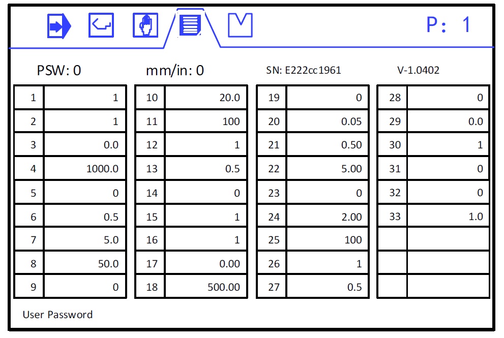
Далее вводите PSW — 9639, и Вы перейдете режим настройки клапанов.
Больше картинок нет, скиньте фотки — подскажу.
Изменено пользователем vad0000
- Цитата
Ссылка на сообщение
Поделиться на других сайтах
homolud
0
- Автор
-
- Жалоба
- Рассказать
Спасибо большое. Получается вся вкуснота у него спрятана под разными паролями.
- Цитата
Ссылка на сообщение
Поделиться на других сайтах
vad0000
388
-
- Жалоба
- Рассказать
9 минут назад, homolud сказал:
Получается вся вкуснота у него спрятана под разными паролями
Это не только у него.
У ESTUN тоже самое. Только пароли другие 
- Цитата
Ссылка на сообщение
Поделиться на других сайтах
- 1 месяц спустя…
papa56
0
-
- Жалоба
- Рассказать
Имею такой же листогиб. Один в один.
Тоже одна скорость опускания траверсы. Концевик рабочего хода есть, заведён в шкаф.
Для появления рабочего хода нужно поменять гидравлику заменив плиту и пр.
Схема есть, есть китайцы с плитами и пр. Но что бы сделать заказ нужна какая то спецификация с маркировкой плиты, соленоидов, как я понимаю. С китайцами сложно это обсуждать, опасаюсь ошибки.
Никак не могу найти человека, который в этом разбирается и смог бы помочь купить и собрать.
Может чего не догоняю… Засада какая то…
Прошу отозваться понимающего в этом деле и дать совет или собрать эту шнягу.
- Цитата
Ссылка на сообщение
Поделиться на других сайтах
homolud
0
- Автор
-
- Жалоба
- Рассказать
А можно схему и китайцев с плитами?
- Цитата
Ссылка на сообщение
Поделиться на других сайтах
- Назад
- 1
- 2
- Вперёд
- Страница 2 из 2
Присоединяйтесь к обсуждению
Вы можете опубликовать сообщение сейчас, а зарегистрироваться позже.
Если у вас есть аккаунт, войдите в него для написания от своего имени.
Примечание: вашему сообщению потребуется утверждение модератора, прежде чем оно станет доступным.
-
Сейчас на странице
0 пользователей
Нет пользователей, просматривающих эту страницу.
-
Сообщения
-
Автор:
Bot · Опубликовано:
Компания C3D Labs объявляет о расширении набора форматов, поддерживаемых модулем обмена данными C3D Converter. Впервые ими стали нативные форматы зарубежных CAD-систем: NX и SolidWorks. C3D Converter отвечает за чтение и запись 3D-моделей в различных обменных форматах. Модуль конвертации входит в состав C3D Toolkit — набора инструментов для разработчиков инженерного программного обеспечения. Именно C3D Converter обеспечивает возможность обмена данными между САПР, построенными на ядре C3D, и другими сложными программными продуктами. Традиционно C3D Labs делала ставку на популярные обменные форматы, такие как STEP или JT. В компании была накоплена существенная компетенция по форматам геометрических ядер ACIS и Parasolid. Сегодня, в условиях реального импортозамещения, поддержка только обменных форматов оказывается недостаточной. В случае работы в мульти-CAD среде, а также в случае миграции с зарубежных САПР на отечественные гораздо удобнее работать напрямую с […]
View the full article
-
Автор:
Toni Galuzo · Опубликовано:
Я попробовал, даже небольшую программку скинул, которая последовательно переходит между СК с 54 по 58. Тот же результат.
-

Автор:
Ninja · Опубликовано:
интересная мысль, осталось только «ГЛЯНУТЬ» )) Будет время погляди пожалуйста!@vanek77777 , одна надежда на тебя…
@maxx2000 ну куда ты лезешь со своими 2-я классами церковно-приходской школы, которую так и не окончил в следствии врождённого слабоумия ))))
Вот у меня конкретно файл turning.prt изменёт так как надо! НО, настройки из него не передаются во вновь созданный проект! И чё теперь делать?
Создаёшь новый проект, из turning создаёшь новую операцию а настройки в ней старые, в то же время в самом turning.prt настройки новые. -
Автор:
DuS · Опубликовано:
Нет. Посмотрите ЕСКД.
Я в вашем случае руками ужимал графы и занимал графу примечания.
Автоматически вы ничего не сделаете.
Если исполнений больше 9 то используется такая форма записи
-
Автор:
Udav817 · Опубликовано:
ни разу не встречал, чтобы у SE именно так работало. Либо, либо — да. Он или сжимает текст, но не переносит, либо переносит, но не сжимает.
В графе «наименование» на чертеже очень не хватает именно такого функционала. в спецификашке такого тоже не видел. приходится каждый раз вручную всякими «%RT» переносы делать.
-
Автор:
Alemix · Опубликовано:
Именно так и хотелось бы, чтоб плиты были в допуске. Только не +, а -0,02. Обычно так делаем.
-
Автор:
Bot · Опубликовано:
Оригинал в блоге компании C3D Labs
Компания Иторум выбрала инструмент C3D Toolkit — специализированную библиотеку для разработки инженерного программного обеспечения, отвечающую за построение, редактирование, визуализацию и конвертацию геометрических моделей — для создания отечественного решения Technical Documentation Editor 3D (TDE 3D). Компоненты C3D Vision (включающий также функционал web-визуализации) и C3D Converter помогают создавать 2D и 3D-графику для интерактивной электронной технической документации и средств обучения.
Модуль визуализации C3D Vision дает возможность не только разрабатывать и использовать 2D и 3D-графику в десктопных приложениях под управлением ОС Windows и Linux, но и размещать ее на специализированном web-сервере для технической документации Technical Documentation Server. Это обеспечивает интерактивное взаимодействие с 3D-моделями посредством любого интернет-браузера.
За счет […]
View the full article -
Автор:
lem_on · Опубликовано:
Свершилось, друг спас друга, поехал на замену уплотнений револьвера и там как раз то что нужно. Пока револьвер раскидан, выдернул евойный блок и прислал мне фотки. Навесным монтажем прилепил резистор, взял обычный, смд ждать надо было, межслойные отверстия рассверлил и продел жилку провода, убрал отслоившийся текстолит и залил все зелёнкой. Блок проснулся сразу после контрольного подачи напряжения и заработал непосредственно в станке.
Фото исправной платы, если кто будет иметь подобное удовольствие. В январе станок уедет ко мне на ПМЖ.
-
Автор:
lem_on · Опубликовано:
Не знаю есть ли там меню обслуживания магазина, но надо вручную забить номера инструмента в магазине, освободить шпиндель.
-
-


Главное содержание
Контроллеры станков с ЧПУ
- Контроллер ESTUN E21 v. 1.06 (русский) — Руководство по эксплуатации (инструкция) контроллера для гидравлических листогибов.

- Контроллер ESTUN E21S v. 1.06 (русский) — Руководство по эксплуатации (инструкция) контроллера для гидравлических листорезных станков.

- Контроллер ESTUN E210 v. 1.02 (русский) — Руководство по эксплуатации (инструкция) контроллера для гидравлических листогибов.

- Контроллер DELEM DA-52s V0812 для ПО Вер.3.2 (русский) — Руководство по эксплуатации (инструкция) контроллера для гидравлических листогибов.

- JQ LASER BCS100 (русский) V.2.25 — Руководство пользователя контроллера высоты для станков лазерной резки металла с ЧПУ

- Контроллер PA 8000 Ред.04.09 Вер.ПО 3.Х (русский) — Руководство по эксплуатации (инструкция) контроллера.

Контроллер распределенного мониторинга температуры OTS3/LHD3
-
Контроллеры серии OTS3/LHD3 — инструкции по безопасности
-
Контроллеры серии OTS3/LHD3 — руководство по установке
-
Контроллеры серии OTS3/LHD3 — руководство по эксплуатации