
Подбор рекомендованного аналога
Заполните форму, и мы обязательно с Вами свяжемся
Похожая группа товаров
Контроллеры производительности Р-КП Ридан
Основной функцией контроллера давления и температуры является управление центральной холодильной машиной таким образом, чтобы система постоянно работала в наиболее энергетически выгодном режиме охлаждения.
Бренд:Ридан
Предприятие обеспечивает полный производственный цикл,
включая производство пластин, плит, элементов рам и других комплектующих.
Локализация достигает 95%, мощность предприятия составляет более 20 тыс.
изделий в год.
- Напряжение питания
- 24 В перем.тока 50Гц;
- Количество цифровых входов
- 6
- Поддержка сети передачи данных
- Модбас
- Количество цифровых выходов
- 6
- Количество аналоговых выходов
- 2
Руководство
Скачать
Письмо о замене
Письмо о замене
Письмо о замене
Скачать
- Поддержка сетевых карт
- нет
- Температура хранения
- от -40 до 70
- Класс защиты корпуса
- IP20
- Количество цифровых выходов
- 6
- Количество аналоговых выходов
- 2
- Управление Компрессорами
- 4
- Управление Двумя группами всасывания
- нет
- Управление скоростью лидерного компрессора
- да
- Управление компрессором ШИМ сигналом
- да
- Входов защиты на компрессор
- 1
- Общая защита всей централи
- да
- Управление вентиляторами Конденсатора
- да
- Максимальное число ступеней вентиляторов
- 4
- Плавное управление производительностью вентиляторов
- да
- Защитный мониторинг вентиляторов конденсатора
- общий вход
- Дополнительные датчики
- да
- Дополнительные входы аварийного мониторинга
- 1
- Встроенный дисплей
- да
- Подключение дисплея MMIGR
- да
- Поддержка сети передачи данных
- Модбас
- Рабочая температура
- от — 20 до 60 С
- Количество цифровых входов
- 6
- Напряжение питания
- 24 В перем.тока 50Гц;
- Модель
- AK-PC 351
- Назначение изделия
- Основной функцией контроллера давления и температуры является управление центральной холодильной машиной таким образом, чтобы система постоянно работала в наиболее энергетически выгодном режиме охлаждения.Управление ступенями производительности компрессоров;
Управление ступенями производительности вентиляторов;
Управление скоростью вращения одного из компрессоров;
Управление скоростью вращения вентиляторов конденсатора;
Управление компрессорами с ШИМ сигналом. - Комплектность
- В комплект поставки входят:- контроллер давления и температуры типа AK-PC;
— упаковочная коробка;
— инструкция. - Гарантийные обязательства
- Изготовитель/продавец гарантирует соответствие контроллеров давления и температуры типа AK-PC техническим требованиям при соблюдении потребителем условий транспортирования, хранения и эксплуатации.Гарантийный срок эксплуатации и хранения контроллеров – 12 месяцев с даты продажи, указанной в транспортных документах, или 18 месяцев с даты производства.
Срок службы контроллеров давления и температуры типа AK-PC при соблюдении рабочих диапазонов согласно паспорту/инструкции по эксплуатации и проведении сервисных работ – 10 лет с даты продажи, указанной в транспортных документах. - Количество аналоговых входов
- 4
- Встроенная сетевая карта
- Модбас
- Количество реле
- 6
Руководство
Скачать
Письмо о замене
Письмо о замене
Письмо о замене
Скачать
![]()
User Guide
Capacity Controller
AK-PC 351
ADAP-KOOL® Refrigeration Control System

Introduction
Application
The controller is used for capacity regulation of compressors
and condensers in small refrigeration applications. A maximum of 4 compressors and one condenser can be regulated. For example:
•One suction group + one condenser group, max. 6 steps total
•One compressor group, max. 4 steps
•One condenser group, max. 4 steps
Advantages
•Energy savings via:
—Optimisation of suction pressure
—Night set back
—Floating condensing pressure
Input and output
There are a limited number of available inputs and outputs. For each signal type, though, the following can be connected:
• Analogue inputs, max. 4 pcs.
Signal from 2 pressure transmitters and 2 temperature sensors
• Digital inputs, max. 8 pcs.
Signal from automatic safety control, external start stop, night signal, general alarm.
• Relay outputs, max. 5 pcs.
Connection of compressors, condenser fans, alarm relay
• Solid state outputs, max. 1 pcs.
Control of bypass on a digital scroll or for controlling unloader on a stream compressor. If the output is not used for this function, it can be used as ordinary relay output
• Analogue outputs, max. 2 pcs.
Speed control of compressors and condenser fans.
Operation
The daily operation can be set up directly on the controller. During set-up, the display images will be adjusted so that only the relevant images are opened for additional setting and end-user operation.
The operation is password protected, and three levels of access can be granted.
The controller contains several languages. Select the preferred language at start-up.
Data communication
The controller has built-in Modbus data communication, and it can be connected to an AK-SM 800 type system device.
|
2 |
User Guide RS8GZ402 © Danfoss 2017-04 |
AK-PC 351 |
Suction Group
Compressor types
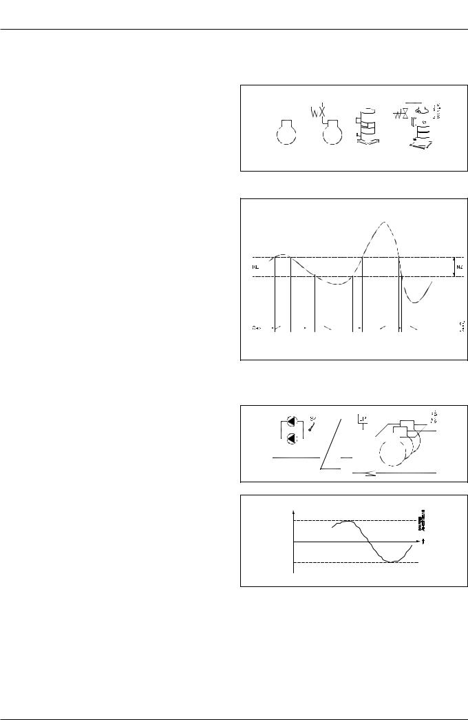
The following types of compressor combinations can be used for regulation:
•Single-step compressors
•Speed controlled compressor together with single-step
•Digital scroll compressor together with single-step
•Stream 4 cylinder compressor together with single-step
•Compressors with an equal number of unloaders.
Capacity regulation
The cut-in capacity is controlled by signals from the connected pressure transmitter/temperature sensor and the set reference. Set a neutral zone around the reference .
In the neutral zone the pressure is controlled by the regulating compressor. When it can no longer maintain the pressure within the neutral zone, the controller will cut out or cut in the next compressor in the sequence.
When further capacity is either cut out or cut in, the capacity from the regulating compressor will be modified accordingly to maintain the pressure within the neutral zone (only where the compressor has variable capacity).
–When the pressure is higher than the “reference + a half neutral zone”, cut-in of the next compressor (arrow up) is permitted.
–When the pressure is lower than the “reference — a half neutral zone”, cut-out of a compressor (arrow down) is permitted.
–When the pressure is within the neutral zone, the process will continue with the currently activated compressors.
Control sensor
Normally, a suction group is controlled based on a signal from the Po pressure transmitter.
If control on a brine, the S4 sensor must be the control sensor.
An external, low-pressure switch can be connected to DI7 for frost protection.
The reference
At set or variable reference can be used for regulation. For example, the variable reference can be used for a night time increase or Po optimisation. Enter a set point here so that a contribution from the Po optimisation or night time increase is added. This contribution can raise or lower the reference, as determined by the momentary cooling need.
To limit the reference from values that are too high or too low, set a max. and min. limit.
|
AK-PC 351 |
User Guide RS8GZ402 © Danfoss 2017-04 |
3 |
Condenser
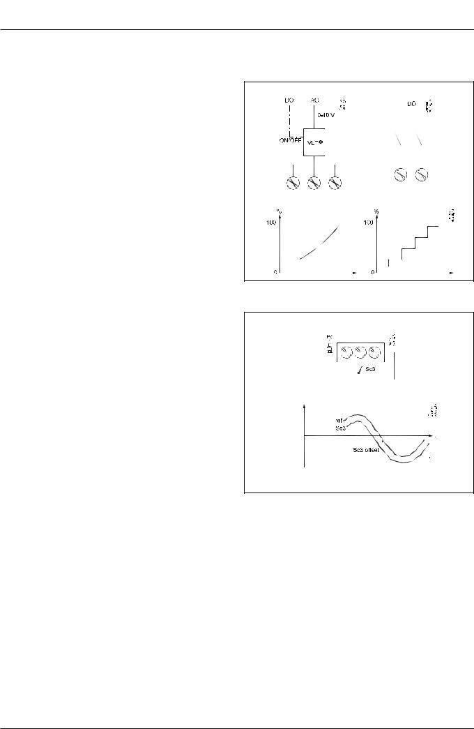
Fan control
The fans can be controlled incrementally using the controller’s relays, or they can be speed-controlled via the controller’s analogue output.
Speed control can be via a frequency VLT-type transformer.
If the fans have EC motors, the 0-10 V signal can be used directly.
Control
Regulation is carried out based on a signal from the Pc pressure transmitter or an S7 media temperature sensor. The signal is compared with the regulation reference.
The regulation reference can originate from one or more of the following functions:
•Fixed reference
•Variable reference, which follows the outdoor temperature. When the outdoor temperature drops, the reference will drop by a corresponding amount.
This variable reference requires the installation of an Sc3 outdoor temperature sensor. The sensor must be positioned so that it registers the correct outdoor temperature. In other words, it must be shielded from direct sunlight and located near the airway of the condenser.
This regulation requires setting a min. and max. reference, so that the regulation process is kept within the given limits.
Media temperature
If controlling a media temperature, the control sensor must be set to S7. This temperature sensor must be located in the desired medium.
High-pressure monitoring can occur with an external, high-pres- sure switch on DI8.
|
4 |
User Guide RS8GZ402 © Danfoss 2017-04 |
AK-PC 351 |

Safety functions
Min./max. suction pressure Po
The suction pressure is recorded continuously.
If the measured value falls below the set minimum limit, the compressors will immediately cut out.
If it exceeds the max. value, an alarm will be generated once the time delay has elapsed.
Max. condensing pressure Pc
If the condensing pressure reaches the upper permissible value, the controller will connect all condenser fans to keep the pressure down. At the same time, a portion of the compressor capacity will be disconnected. If the pressure remains near the threshold value, even more compressors will be disconnected.
All compressors will be disconnected immediately if the threshold value is exceeded.
LP switch
On/off signal on a DI7 input
If a signal is received, all compressors will immediately be stopped. When the signal is removed again, the capacity is regulated up again.
HP switch
On/off signal on a DI8 input
If a signal is received, all compressors will immediately be stopped. Fan capacity will increase depending on how much the
Pc measurement exceeds the reference.
When the signal is removed again, the capacity is regulated up again.
Max. discharge gas temperature Sd for digital scroll / stream
Temperature sensor on an AI input.
A signal can be received from a Pt 1000 Ohm sensor on the pressure pipe.
If the temperature nears the set max. temperature, the capacity of the compressor will be increased so that the compressor can cool down itself.
The compressors will be stopped if the temperature reaches up to the set max. temperature value.
Sensor failure
If lack of signal from one of the connected temperature sensors or pressure transmitters is registered an alarm will be given.
•In the event of a Po error (S4 error), regulation will continue with a set capacity in daytime operation (e.g. 50%), and a set capacity in night operation (e.g. 25%), but with a minimum of one step.
•In the event of a Pc error, the condenser capacity that corresponds to how much compressor capacity is connected will cut in. Compressor regulation will remain normal.
•When there is an error on the Sd sensor the safety monitoring of the discharge gas temperature will be discontinued.
•In the event of an error on the outdoor temperature sensor,
Sc3, the permanent setting value will be used as a reference.
NB: A faulty sensor must be OK within 10 minutes before a sensor alarm is cancelled.
General DI alarm
On/off signal on a DI8 input
If the input is used as general alarm input alarm text and delay times can be connected.
Alarm and text will appear when the delay time has elapsed.
|
AK-PC 351 |
User Guide RS8GZ402 © Danfoss 2017-04 |
5 |

Display overview
End-user overview
The images in this daily user interface will depend on how the set-up is made. They will illustrate what is regulated. For example: One suction group, one condenser group, or a combination. See examples below:
1suction groupe
1condenser group
1suction group and
1condenser group
Press «Enter»
to get to the overview
When an alarm is sent from the controller, you must advance to this
display to see the alarm text.
Select a line and press «Enter»
|
Status = either 1 suction group or |
1 condenser group |
or |
Both suction group |
|
and condenser group |
|
Parameters |
Access to the menus requires pass- |
|
word. |
|
|
Level 1: Only view (100) |
|
|
Level 2: Change values (200) |
|
|
Level 3: Change configuration (300). |
|
6 |
User Guide RS8GZ402 © Danfoss 2017-04 |
AK-PC 351 |
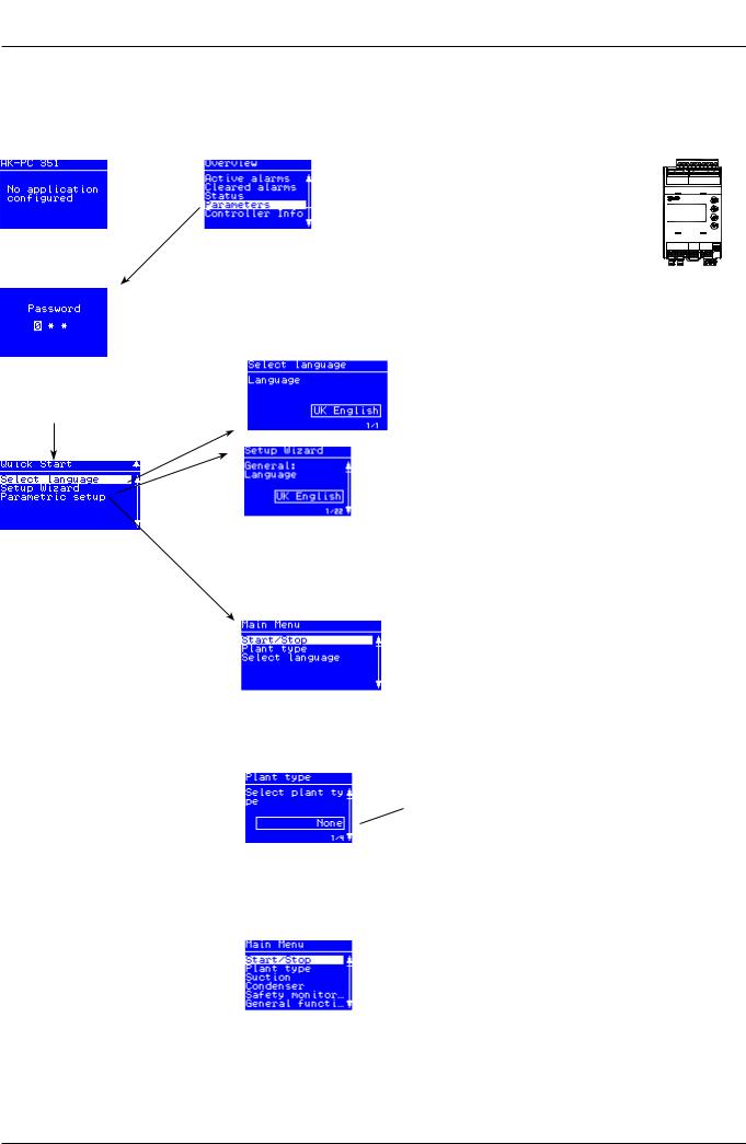
Set-up overview
There are two ways in which the controller can be set up. Select the one that is easiest for you: either “Wizard” or a review of “all parameters”.
Start screen upon delivery
Operating principles
1. Select position using arrow keys
2. Select using “Enter”
3. Use the “X” to return
|
Press “Enter” |
Hold “Enter” down for 2 sec- |
|
onds to come to password entry |
The default password upon delivery is 300. Use the arrow keys to set the password. End by pressing “Enter”
Wizard
Here you will be led through a series of settings, after which the controller will be ready for start.
Image 1 of 22 is displayed here.
Select a set-up method. End by pressing “Enter”
|
Main Menu |
||
|
The first setting is the |
The following options are available here: |
|
|
Plant type |
||
|
• Comp. + Cond. = suction group and condenser |
||
|
• Condenser = ondenser only |
||
|
• Compressor = suction group only |
||
|
• None |
||
|
When the Plant type has |
||
|
been selected, it will al- |
||
|
low several settings to be |
||
|
made. |
||
|
For example: |
Continue to the next menus.
All settings are explained on the pages that follow
|
AK-PC 351 |
User Guide RS8GZ402 © Danfoss 2017-04 |
7 |
 Loading…
You can only view or download manuals with
Sign Up and get 5 for free
Upload your files to the site. You get 1 for each file you add
Get 1 for every time someone downloads your manual
Buy as many as you need
Настройка может осуществляться непосредственно с кнопок контроллера. Во время настройки параметры на дисплее могут задаваться таким образом, что только необходимые параметры будут открываться для дополнительных настроек и выполнения операций пользователем. Функции управления защищены паролем, и может быть предоставлено три уровня доступа. В контроллере предусматривается использование нескольких языков. Требуемый язык может быть выбран при вводе в эксплуатацию.
Регулирование холодопроизводительности
Холодопроизводительность включения определяется сигналами от подключенного датчика давления / датчика температуры и заданной уставкой. Вблизи уставки должна быть задана нейтральная зона. Внутри нейтральной зоны холодопроизводительность компрессора регулируется таким образом, чтобы можно было поддерживать давление. Когда станет невозможным поддержание давления в пределах нейтральной зоны, контроллер выключит или включит следующий компрессор. При дальнейшем подключении или отключении дополнительной холодопроизводительности, холодопроизводительность регулируемого компрессора будет соответствующим образом изменяться, чтобы поддерживать давление в пределах нейтральной зоны (только в том случае, если можно плавно регулировать холодопроизводительность компрессора).
– Если давление выше величины “уставка + половина нейтральной зоны”, разрешается включение следующего компрессора (стрелка вверх).
– Если давление ниже величины “уставка — половина нейтральной зоны”, разрешается выключение компрессора (стрелка вниз).
– Если давление находится в нейтральной зоне, продолжается работа с включенными в данное время компрессорами.
| Напряжение питания | 24 В пер. тока +/-15% 50/60 Гц, 17ВА 24 В пост. тока (20-60 В), 17ВА |
|
| 4 аналоговых входа | Измерение давления: Измерительный преобразователь давления модель AKS 32R Измерительный преобразователь давления 1-5 В, модель AKS 32 Измерительный преобразователь давления 0-20 (4-20) мА, модель AKS 33 |
|
| Измерение температуры Pt 1000 Ом / 0 °C или NTC — 86K для компрессоров типа Digital Scroll / Stream |
||
| 8 дискретных входов | Сигнал от сухих контактов для выполнения, например, следующих функций: Пуск / останов регулирования Мониторинг цепей защиты Предупредительный сигнал общего назначения |
|
| Релейный выход для регулирования холодопроизводительности | 5 шт. SPDT (5 А) | AC-1: 5 A (активная нагрузка) AC-15: 2 А (индуктивная нагрузка) |
| 1 полупроводниковое реле ШИМ для Scroll-разгрузки | Imax. = 0,5 А Imin. = 50 мА Leak<1,5 мА |
|
| 2 выхода напряжения | 0-10 В Ri = 1 кОм | |
| Выход для дисплея | Для типа MMIGRS2 | |
| Передача данных | Modbus для AK-SC 355 или AK-SM 850 | |
| Условия окружающей среды | -20 — 60 °C при эксплуатации -40 — 70 °C при перевозке |
|
| Относительная влажность 20 — 80%, без конденсации | ||
| Отсутствие ударов и вибрации | ||
| Степень защиты | IP 20 | |
| Масса | 0,2 кг | |
| Монтаж | На DIN-рейку | |
| Клеммы подключения | Для многожильных проводов сечением макс. 2,5 мм2 | |
| Сертификация | Выполнение требований директив ЕС для низковольтного оборудования и электромагнитной совместимости с целью маркировки знаком CE Испытания на соответствие требованиям директивы для низковольтного оборудования в соответствии с EN 60730-1 и EN 60730-2-9 Испытания на соответствие требованиям директивы для электромагнитной совместимости в соответствии с EN61000-6-2 и 3 |
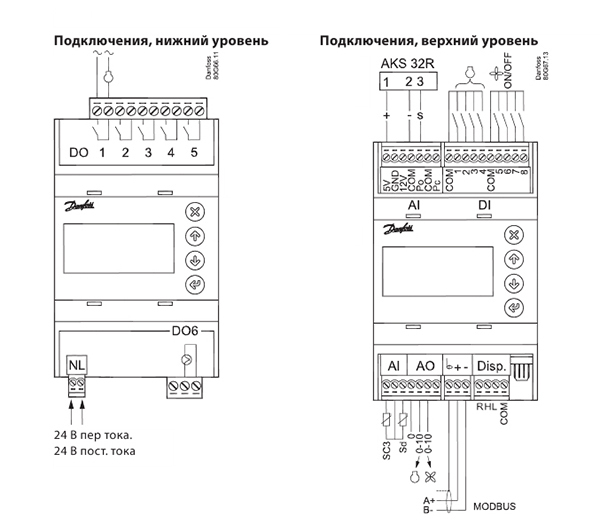
Table of Contents: Danfoss AK-PC 351 Controller Owner’s Manual
-
AK-PC 351 User Guide RS8GZ302 © Danfoss 2015-06 19 The capacity is divided into period times as «PWM per». 100% capacity is delivered when cooling takes place for the whole period. An o time is required by the bypass valve within the period and an on time is also permitted. There is «no cooling» when the valve is on. The controller itself calculates the capacity needed and will then vary it according to the cut-in time of the capacity control valve. A limit is intro
-
Danfoss AK-PC 351 AK-PC 351 User Guide RS8GZ302 © Danfoss 2015-06 17 Connections when using Setup Wizard The assignment of functions on the respective inputs and outputs can be regulated in “IO conguration”. Here is an example of 3 compressors and 2 fans: Digital outputs (DO1-DO6): If you have used the Setup Wizard for the conguration, the control- ler will automatically assign the outputs in accordance with the following prioritised order: • PWM outputs for digital scroll or Stream compressor will be lo- cated on solid state outputs DO6 • Compressor start and unloaders • Fans • Alarm Digital
-
18 User Guide RS8GZ302 © Danfoss 2015-06 AK-PC 351 Connections AKS 32 AKS 33 AKS 32R Connection, lower level Connection, upper level Supply Voltage. 24 V a.c. or 24 V d.c. DO — Digital outputs, 6 pcs. DO1 — DO6 DO6 is solid state relay. The relays are de-rated to the specied values. If an alarm relay is dened, it will be driven under normal op- eration and it will drop in the event of alarms and insucient power to the controller. DO DO1-DO5 DO6 I Max. 5 A (2) 0.5 A min. 50 mA Io < 1.5 mA U All 24 V or all 230 V A
-
AK-PC 351 User Guide RS8GZ302 © Danfoss 2015-06 21 Ordering Type Function Operation Supply voltage Code no. AK-PC 351 Capacity controller With buttons and display 24 V 080G0289
-
Danfoss AK-PC 351 22 User Guide RS8GZ302 © Danfoss 2015-06 AK-PC 351 List of literature Installation guide for extended operation RC8AC Here you can see how a data communication connection to ADAP-KOOL® Refrigeration control systems can be establis- hed. ADAP-KOOL® Danfoss can accept no responsibility for possible errors in catalogues, brochures and other printed material. Danfoss reserves the right to alter its products without notice. This also applies to products already on order provided that such alternations can be made without subsequential changes being necessary in specications already agreed. All trademarks in this material are property of t
-
Danfoss AK-PC 351 4 User Guide RS8GZ302 © Danfoss 2015-06 AK-PC 351 Condenser Fan control The fans can be controlled incrementally using the controller’s relays, or they can be speed-controlled via the controller’s analogue output. Speed control can be via a frequency VLT-type transformer. If the fans have EC motors, the 0-10 V signal can be used directly. Control Regulation is carried out based on a signal from the Pc pressure transmitter or an S7 media temperature sensor. The signal is com- pared with the regulation reference. The regulation reference can originate from one or more of the followin
-
10 User Guide RS8GZ302 © Danfoss 2015-06 AK-PC 351 Compressor mode Set the type of compressor to be used for regulation: None; 1 single, 2 single, 3 single, 4 single 1 speed, 2 speed, 3 speed, 4 speed, 1 digital, 2 digital, 3 digital 1 stream, 2 stream, 3 stream 1×1 unload, 1×2 unload, 1×3 unload, 2×1 unload Application Single step 1 single 2 single 3 single 4 single Speed on the rst. Then single step 1 speed 2 speed 3 speed 4 speed Digital scroll (stream) on the rst. Then single step 1 digital 2 digital 3 digital Compressors with unloader 1×1 unload 1×2 unload 1×3 unload
-
Danfoss AK-PC 351 14 User Guide RS8GZ302 © Danfoss 2015-06 AK-PC 351 General functions Digital input Digital input There are two general digital inputs that can be used by the controller. DI7 cong The DI7 input can be set to: • Not used • Receive night signal. The signal will raise the suction pressure with set oset. • Register signal from an LP switch. The signal will cause the controller to stop all compressors. DI-demand Night / LP switch Fac: Not used DI8 cong The DI8 input can be set to: • Not used • Register sig
-
Danfoss AK-PC 351 Capacity Controller AK-PC 351 User Guide ADAP-KOOL® Refrigeration Control System
-
Danfoss AK-PC 351 16 User Guide RS8GZ302 © Danfoss 2015-06 AK-PC 351 Alarm priorities General Standby mode: Sensor error: Refrigerant: Output in MANUAL: General alarm; Alarm priorities The controller will issue an alarm notication if a specic incident occurs. Each incident is set to indicate the importance of each alarm, but it is possible to modify the importance of each. Choose from between the following priority levels: Critical: Important alarms that require a high level of attention. Severe: Alarms of intermediate importance Normal: No important alarms
-
AK-PC 351 User Guide RS8GZ302 © Danfoss 2015-06 3 Suction Group Compressor types The following types of compressor combinations can be used for regulation: • Single-step compressors • Speed controlled compressor together with single-step • Digital scroll compressor together with single-step • Stream 4 cylinder compressor together with single-step • Compressors with an equal number of unloaders. Capacity regulation The cut-in capacity is controlled by signals from the connected pressure transmitter/temperature sensor and the set reference. Set a
-
Danfoss AK-PC 351 AK-PC 351 User Guide RS8GZ302 © Danfoss 2015-06 11 PWM Max cycle For scroll Limitation of capacity during time period. There is no limit if the setting in 100%. Min: 60% Max: 100% Fac: 100% Comp. 1 Sd temp. For “Scroll” and “Stream” Dene whether the controller should monitor the discharge gas temperature Sd from a digital scroll or a stream compressor (NTC 86K or Pt 1000 Ohm). AI-demand No / Yes Fac: No Comp. 1 Sd max. For scroll and Stream and yes to “Comp.1 Sd temp” Set the maximum Sd temperature Min: 0°C Max: 195°C Fac: 125°C Compressor timers Compressor timers Lead comp
-
Danfoss AK-PC 351 8 User Guide RS8GZ302 © Danfoss 2015-06 AK-PC 351 Start/stop Main switch Main switch Start and stop regulating here. The conguration settings will require that regulating is stopped. If you try to enter a conguration setting when regulating has started, the controller will ask if regulating should be stopped. When all settings have been made and the main switch is set to “ON”, the controller will enable the display of the various measurements. Regulation will start. (If an external main switch has been dened, it must also be “ON” b
-
Danfoss AK-PC 351 AK-PC 351 User Guide RS8GZ302 © Danfoss 2015-06 7 Start screen upon delivery Set-up overview There are two ways in which the controller can be set up. Select the one that is easiest for you: either “Wizard” or a review of “all parameters”. Hold “Enter” down for 2 sec- onds to come to password entry Press “Enter” Operating principles 1. Select position using arrow keys 2. Select using “Enter” 3. Use the “X” to return Wizard Here you will be led through a series of settings, after which the controller will be ready for start. Image 1 of 22 is displayed here. T
-
AK-PC 351 User Guide RS8GZ302 © Danfoss 2015-06 9 No. of running comp. The number of compressors in operation can be read here Po Pressure The measured pressure for the Po pressure transmitter can be read here To Saturated temp. The measured Po pressure converted to temperature can be read here S4 media temp. The measured S4 sensors actual value can be read here MC Po oset The size of a reference displacement on Po required from the system unit (suct
-
Danfoss AK-PC 351 20 User Guide RS8GZ302 © Danfoss 2015-06 AK-PC 351 Mounting /Dimensions For DIN rail mounting only (IP 20) Supply voltage 24 V a.c. +/-15% 50/60 Hz, 9 VA 24 V d.c. (20-60 V), 9 VA 4 analog Input Pressure meauring: Ratiometric pressure transmitter type AKS 32R 1-5 volt pressure transmitter type AKS 32 0-20 (4-20) mA pressure transmitter type AKS 33 Temperature measurement Pt 1000 ohm/0°C NTC — 86K from digital scroll / stream 8 digital input From contact function E.g. to: Start/stop of regulation Monitoring of safety circuits General alarm function Relay output to capacity control 5 pcs. SPDT (5A) AC-1: 5 A (ohmic) AC-15: 2 A (indu
-
Danfoss AK-PC 351 AK-PC 351 User Guide RS8GZ302 © Danfoss 2015-06 15 I/O conguration Here you can see which outputs and inputs your settings have established. The connection points shown cannot be changed, but the analog input measurements can be adjusted. Digital outputs 1: 2: 3: . 6: On/o outputs The outputs are set up automatically in the following order: a) If a PWM output is needed, place it on DO6 b) Compressors and unloader valves from DO1 and above c) Next, fans d) Alarm (One output can be on or o with an activated relay.) On O Digital inputs 1: 2: 3: .. 8: O
-
2 User Guide RS8GZ302 © Danfoss 2015-06 AK-PC 351 Introduction Application The controller is used for capacity regulation of compressors and condensers in small refrigeration applications. A maximum of 4 compressors and one condenser can be regulated. For example: • One suction group + one condenser group, max. 6 steps total • One compressor group, max. 4 steps • One condenser group, max. 4 steps Advantages • Energy savings via: — Optimisatio
-
Danfoss AK-PC 351 AK-PC 351 User Guide RS8GZ302 © Danfoss 2015-06 13 Fan mode Conguration of fans: Fan speed & DO: Speed controled fans via AO2 and start/stop via DO output. Fan speed: Speed controlled fans via AO2 4 Fan step: step-by-step . Start/stop via 4 pcs. DO outputs 3 Fan step: step-by-step . Start/stop via 3 pcs. DO outputs 2 Fan step: step-by-step . Start/stop via 2 pcs. DO outputs 1 Fan step: step-by-step . Start/stop via 1 pcs. DO outputs Not used For step-by-step connection, the fans cut in and out sequentially (e.g. 123-321). DO-demand AO-demand Fac: Fan speed&DO Control type Normally, PI-regulation is u
-
Danfoss AK-PC 351 AK-PC 351 User Guide RS8GZ302 © Danfoss 2015-06 5 Safety functions Min./max. suction pressure Po The suction pressure is recorded continuously. If the measured value falls below the set minimum limit, the compressors will immediately cut out. If it exceeds the max. value, an alarm will be generated once the time delay has elapsed. Max. condensing pressure Pc If the condensing pressure reaches the upper permissible value, the controller will connect all condenser fans to keep the pressure down. At the same time, a portion of the compressor capacity will be disconnected. If the pressure remains
-
12 User Guide RS8GZ302 © Danfoss 2015-06 AK-PC 351 Condenser Control status Regulation status Control status Here you can read the status of the condenser circuit, e.g.: • Main switch = OFF • Capacity control is ready • Capacity control is in normal run mode • Capacity control is set in manual control mode • Capacity forced to 100% due to High Pc/High Sd prevention functions • Capacity forced to 100% due to external HP switch/HP safety/Sd safety limit violation Control temp./press
Questions, Opinions and Exploitation Impressions:
You can ask a question, express your opinion or share our experience of Danfoss AK-PC 351 device using right now.
 |
[Page 1] Danfoss AK-PC 351 Capacity Controller AK-PC 351 User Guide ADAP-KOOL® Refrigeration Control System |
 |
[Page 2] Danfoss AK-PC 351 2 User Guide RS8GZ302 © Danfoss 2015-06 AK-PC 351 Introduction Application The controller is used for capacity regulation of compressors and condensers in small refrigeration applications. A maximum of 4 compressors and one condenser can be re… |
 |
[Page 3] Danfoss AK-PC 351 AK-PC 351 User Guide RS8GZ302 © Danfoss 2015-06 3 Suction Group Compressor types The following types of compressor combinations can be used for regulation: • Single-step compressors • Speed controlled compressor together with single-step • … |
 |
[Page 4] Danfoss AK-PC 351 4 User Guide RS8GZ302 © Danfoss 2015-06 AK-PC 351 Condenser Fan control The fans can be controlled incrementally using the controller’s relays, or they can be speed-controlled via the controller’s analogue output. Speed control can be via … |
 |
[Page 5] Danfoss AK-PC 351 AK-PC 351 User Guide RS8GZ302 © Danfoss 2015-06 5 Safety functions Min./max. suction pressure Po The suction pressure is recorded continuously. If the measured value falls below the set minimum limit, the compressors will immediately cut out. I… |
 |
[Page 6] Danfoss AK-PC 351 6 User Guide RS8GZ302 © Danfoss 2015-06 AK-PC 351 Display overview End-user overview The images in this daily user interface will depend on how the set-up is made. They will illustrate what is regulated. For example: One suction group, one conde… |
 |
[Page 7] Danfoss AK-PC 351 AK-PC 351 User Guide RS8GZ302 © Danfoss 2015-06 7 Start screen upon delivery Set-up overview There are two ways in which the controller can be set up. Select the one that is easiest for you: either “Wizard” or a review of “all parameters”… |
 |
[Page 8] Danfoss AK-PC 351 8 User Guide RS8GZ302 © Danfoss 2015-06 AK-PC 351 Start/stop Main switch Main switch Start and stop regulating here. The conguration settings will require that regulating is stopped. If you try to enter a conguration setting when regulating… |
 |
[Page 9] Danfoss AK-PC 351 AK-PC 351 User Guide RS8GZ302 © Danfoss 2015-06 9 No. of running comp. The number of compressors in operation can be read here Po Pressure The measured pressure for the Po pressure transmitter can be read here To Saturated temp. The measured Po p… |
 |
[Page 10] Danfoss AK-PC 351 10 User Guide RS8GZ302 © Danfoss 2015-06 AK-PC 351 Compressor mode Set the type of compressor to be used for regulation: None; 1 single, 2 single, 3 single, 4 single 1 speed, 2 speed, 3 speed, 4 speed, 1 digital, 2 digital, 3 digital 1 stream, 2 s… |
 |
[Page 11] Danfoss AK-PC 351 AK-PC 351 User Guide RS8GZ302 © Danfoss 2015-06 11 PWM Max cycle For scroll Limitation of capacity during time period. There is no limit if the setting in 100%. Min: 60% Max: 100% Fac: 100% Comp. 1 Sd temp. For “Scroll” and “Stream” Den… |
 |
[Page 12] Danfoss AK-PC 351 12 User Guide RS8GZ302 © Danfoss 2015-06 AK-PC 351 Condenser Control status Regulation status Control status Here you can read the status of the condenser circuit, e.g.: • Main switch = OFF • Capacity control is ready • Capacity control is … |
 |
[Page 13] Danfoss AK-PC 351 AK-PC 351 User Guide RS8GZ302 © Danfoss 2015-06 13 Fan mode Conguration of fans: Fan speed & DO: Speed controled fans via AO2 and start/stop via DO output. Fan speed: Speed controlled fans via AO2 4 Fan step: step-by-step . Start/stop via … |
 |
[Page 14] Danfoss AK-PC 351 14 User Guide RS8GZ302 © Danfoss 2015-06 AK-PC 351 General functions Digital input Digital input There are two general digital inputs that can be used by the controller. DI7 cong The DI7 input can be set to: • Not used • Receive night sign… |
 |
[Page 15] Danfoss AK-PC 351 AK-PC 351 User Guide RS8GZ302 © Danfoss 2015-06 15 I/O conguration Here you can see which outputs and inputs your settings have established. The connection points shown cannot be changed, but the analog input measurements can be adjusted. Digi… |
 |
[Page 16] Danfoss AK-PC 351 16 User Guide RS8GZ302 © Danfoss 2015-06 AK-PC 351 Alarm priorities General Standby mode: Sensor error: Refrigerant: Output in MANUAL: General alarm; Alarm priorities The controller will issue an alarm notication if a specic incident occurs…. |
 |
[Page 17] Danfoss AK-PC 351 AK-PC 351 User Guide RS8GZ302 © Danfoss 2015-06 17 Connections when using Setup Wizard The assignment of functions on the respective inputs and outputs can be regulated in “IO conguration”. Here is an example of 3 compressors and 2 fans: … |
 |
[Page 18] Danfoss AK-PC 351 18 User Guide RS8GZ302 © Danfoss 2015-06 AK-PC 351 Connections AKS 32 AKS 33 AKS 32R Connection, lower level Connection, upper level Supply Voltage. 24 V a.c. or 24 V d.c. DO — Digital outputs, 6 pcs. DO1 — DO6 DO6 is solid state relay. The rel… |
 |
[Page 19] Danfoss AK-PC 351 AK-PC 351 User Guide RS8GZ302 © Danfoss 2015-06 19 The capacity is divided into period times as «PWM per». 100% capacity is delivered when cooling takes place for the whole period. An o time is required by the bypass valve within the… |
 |
[Page 20] Danfoss AK-PC 351 20 User Guide RS8GZ302 © Danfoss 2015-06 AK-PC 351 Mounting /Dimensions For DIN rail mounting only (IP 20) Supply voltage 24 V a.c. +/-15% 50/60 Hz, 9 VA 24 V d.c. (20-60 V), 9 VA 4 analog Input Pressure meauring: Ratiometric pressure transmitter … |
 |
[Page 21] Danfoss AK-PC 351 AK-PC 351 User Guide RS8GZ302 © Danfoss 2015-06 21 Ordering Type Function Operation Supply voltage Code no. AK-PC 351 Capacity controller With buttons and display 24 V 080G0289 |
 |
[Page 22] Danfoss AK-PC 351 22 User Guide RS8GZ302 © Danfoss 2015-06 AK-PC 351 List of literature Installation guide for extended operation RC8AC Here you can see how a data communication connection to ADAP-KOOL® Refrigeration control systems can be establis- hed. ADAP-KO… |