
Представленные на сайте изображения автомобилей могут отличаться от автомобилей, доступных в дилерских центрах. Отображение цветов на экранах различных устройств может незначительно отличаться от цвета реального автомобиля. В стандартное оборудование автомобилей могут входить не все опции и варианты отделки интерьера и экстерьера, видимые на изображениях. Некоторые опции могут быть доступны за дополнительную плату.
Любая информация, размещенная на данном сайте, носит исключительно справочный характер и ни при каких обстоятельствах не является публичной офертой, определяемой положениями Статьи 437 (2) Гражданского кодекса Российской Федерации. Все цены, указанные на сайте, не являются окончательными и устанавливаются дилерскими центрами на индивидуальной основе. Для получения подробной информации, обращайтесь в официальные дилерские центры.
Бренд Opel не гарантирует своевременность, точность и полноту информации на сайте, а также беспрепятственный доступ к сайту в любое время. Опубликованная на данном сайте информация может быть изменена в любое время без предварительного уведомления.
Manufacturer: OPEL, Model Year: 2020,
Model line: GRANDLAND X,
Model: OPEL GRANDLAND X 2020
Pages: 335, PDF Size: 21.95 MB
Trending: Неисправности, Рулевое колесо, Круиз контроль, очистка газов, Багажник, stop start, Индикатор
Page 1 of 335

Page 2 of 335

Page 3 of 335

Page 4 of 335

Page 5 of 335

Page 6 of 335
Page 7 of 335

Page 8 of 335

Page 9 of 335

Page 10 of 335

- Load next 10 pages
Trending: stop start, Круиз контроль, Неисправности, adblue, Индикатор, автомат, очистка газов
View, print and download for free: OPEL GRANDLAND X 2020 Инструкция по эксплуатации (in Russian), 335 Pages, PDF Size: 21.95 MB. Search in OPEL GRANDLAND X 2020 Инструкция по эксплуатации (in Russian) online. CarManualsOnline.info is the largest online database of car user manuals. OPEL GRANDLAND X 2020 Инструкция по эксплуатации (in Russian) PDF Download.
All product names, logos, and brands are property of their respective owners.
Privacy Policy | About Us & Contact

Summary of Content for Opel Grandland X 2019 Owner’s Manual PDF
Introduction ……………………………… 2 In brief …………………………………….. 6 Keys, doors and windows ………… 21 Seats, restraints ……………………… 44 Storage …………………………………. 68 Instruments and controls …………. 78 Lighting ……………………………….. 113 Climate control ……………………… 123 Driving and operating …………….. 134 Vehicle care …………………………. 201 Service and maintenance ………. 240 Technical data ……………………… 246 Customer information ……………. 259 Index …………………………………… 270
Contents
2 Introduction
Introduction
Introduction 3
Vehicle specific data Please enter your vehicle’s data on the previous page to keep it easily accessible. Please refer to the sections «Service and maintenance», «Technical data», the vehicles identification plate and national registration documents.
Introduction Your vehicle is a designed combination of advanced technology, safety, environmental friendliness and economy. This Owner’s Manual provides you with all the necessary information to enable you to drive your vehicle safely and efficiently. Make sure your passengers are aware of the possible risk of accident and injury which may result from improper use of the vehicle. You must always comply with the specific laws and regulations of the country that you are in. These laws may differ from the information in this Owner’s Manual.
Disregarding the description given in this manual may affect your warranty. When this Owner’s Manual refers to a workshop visit, we recommend your Opel Service Partner. All Opel Service Partners provide first-class service at reasonable prices. Experienced mechanics trained by Opel work according to specific Opel instructions. The customer literature pack should always be kept ready to hand in the vehicle.
Using this manual This manual describes all options
and features available for this model. Certain descriptions, including those for display and menu functions, may not apply to your vehicle due to model variant, country specifications, special equipment or accessories.
The «In brief» section will give you an initial overview.
The table of contents at the beginning of this manual and within each section shows where the information is located.
The index will enable you to search for specific information.
This Owner’s Manual depicts left- hand drive vehicles. Operation is similar for right-hand drive vehicles.
The Owner’s Manual uses the engine identifier code. The corresponding sales designation and engineering code can be found in the section «Technical data».
Directional data, e.g. left or right, or front or back, always relate to the direction of travel.
Displays may not support your specific language.
Display messages and interior labelling are written in bold letters.
4 Introduction
Danger, Warnings and Cautions
9 Danger
Text marked 9 Danger provides information on risk of fatal injury. Disregarding this information may endanger life.
9 Warning
Text marked 9 Warning provides information on risk of accident or injury. Disregarding this information may lead to injury.
Caution
Text marked Caution provides information on possible damage to the vehicle. Disregarding this information may lead to vehicle damage.
Symbols Page references are indicated with 3. 3 means «see page». Page references and index entries refer to the indented headings given in the section table of content. We wish you many hours of pleasurable driving. Your Opel Team
6 In brief
In brief
Initial drive information
Vehicle unlocking
Press c to unlock the vehicle. Open the doors by pulling the handles. Press P to unlock the tailgate only.
Tailgate
After unlocking, press the tailgate button and open the tailgate. Radio remote control 3 22. Central locking system 3 24. Electronic key system 3 23. Load compartment 3 30.
In brief 7
Seat adjustment Longitudinal adjustment
Pull handle, slide seat, release handle. Try to move the seat back and forth to ensure that the seat is locked in place. Seat position 3 45. Manual seat adjustment 3 46.
Backrests inclination
Turn handwheel. Do not lean on backrest when adjusting. Seat position 3 45. Manual seat adjustment 3 46.
Seat height
Lever pumping motion up : seat higher down : seat lower
Seat position 3 45. Manual seat adjustment 3 46.
8 In brief
Seat inclination
Press switch top : front end higher bottom : front end lower
Seat position 3 45. Manual seat adjustment 3 46.
Head restraint adjustment
Press release button, adjust height, engage. Head restraints 3 44.
Seat belt
Pull out the seat belt and fasten in belt buckle. The seat belt must not be twisted and must fit close against the body. The backrest must not be tilted back too far (maximum approx. 25). To unfasten belt, press red button on belt buckle. Seat position 3 45. Seat belts 3 51. Airbag system 3 54.
In brief 9
Mirror adjustment Interior mirror
To adjust the mirror, move the mirror housing in the desired direction. Manual anti-dazzle interior mirror 3 39. Automatic anti-dazzle interior mirror 3 39.
Exterior mirrors
Select the relevant exterior mirror by pushing the mirror button to the left or right. Adjust respective mirror by the four-way control. Convex mirrors 3 37. Electric adjustment 3 37. Folding mirrors 3 38. Heated mirrors 3 38.
Steering wheel adjustment
Unlock lever, adjust steering wheel, then engage lever and ensure it is fully locked. Do not adjust steering wheel unless vehicle is stationary and steering wheel lock has been released. Seat position 3 45. Ignition positions 3 135.
10 In brief
Instrument panel overview
In brief 11
1 Power windows ………………… 40 2 Exterior mirrors ………………… 37 3 Side air vents …………………. 131 4 Turn lights, headlight
flash, low / high beam, high beam assist …………….. 118
Exit lighting ……………………. 122
Parking lights …………………. 119
Buttons for Driver Information Centre ………….. 100
5 Cruise control ………………… 157
Speed limiter ………………….. 160
Heated steering wheel ………. 79 6 Instruments ……………………… 90
Driver Information Centre …. 100 7 Infotainment controls 8 Windscreen wiper and
washer, rear wiper and washer …………………………… 80
9 Power button ………………….. 136 10 Centre air vents ……………… 131 11 Hazard warning flashers …. 118 12 Info Display …………………… 102
13 Anti-theft alarm system status LED ……………………… 35
14 Central locking system ………. 24 15 Glovebox ………………………… 68 16 Controls for Info Display
operation ……………………….. 102 17 Climate control system …….. 124 18 USB charging port ……………. 84 19 Power outlet …………………….. 84 20 Parking assist / Advanced
parking assist ………………… 175
Lane departure warning ….. 188
Eco button for stop-start system …………………………… 139
Electronic Stability Control and Traction Control ……….. 154
Sport mode ……………………. 157 21 Manual transmission ………. 150
Automatic transmission …… 147 22 Electric parking brake ……… 151 23 Selective ride control ………. 155 24 Ignition switch ………………… 135 25 Steering wheel adjustment . . 79
26 Horn ………………………………. 80 27 Storage …………………………… 68 28 Bonnet release lever ………. 203 29 Light switch …………………… 113
Headlight range adjustment ……………………. 115
Front / rear fog lights ………. 119
Instrument illumination ……. 120
In brief 13
Exterior lighting
AUTO : automatic light control switches automatically between daytime running light and headlight
8 : sidelights 9 : headlights
Automatic light control 3 114.
Fog lights Press button in light switch: > : front fog lights
: rear fog light
Headlight flash and high beam
pull stalk : headlight flash push stalk : high beam
High beam 3 114. High beam assist 3 115. Headlight flash 3 114. LED headlights 3 115.
Turn lights
stalk up : right turn light stalk down : left turn light
Turn lights 3 118. Parking lights 3 119.
14 In brief
Hazard warning flashers
Operated by pressing . Hazard warning flashers 3 118.
Horn
Press j.
Washer and wiper systems Windscreen wiper
HI : fast LO : slow INT : interval wiping
or AUTO : automatic wiping with rain
sensor OFF : off
For single wipe when the wiper is off, press stalk down to position 1x. Windscreen wiper 3 80.
In brief 15
Windscreen washer
Pull stalk. Windscreen washer system 3 80. Washer fluid 3 206. Wiper blade replacement 3 208.
Rear window wiper
Turn outer cap to activate the rear window wiper: OFF : off INT : intermittent operation ON : continuous operation
Rear window washer
Push stalk. Washer fluid is sprayed on the rear window and the wiper wipes a few times. Rear window wiper / washer 3 82.
16 In brief
Climate control Heated rear window Heating and ventilation system, air conditioning system
The heating is operated by pressing b.
Electronic climate control system
The heating is operated by pressing b. Heated rear window 3 41.
Heated exterior mirrors Pressing b also activates the heated exterior mirrors. Heated exterior mirrors 3 38.
Demisting and defrosting the windows
Heating and ventilation system, air conditioning system
press , the air distribution is directed towards the windscreen
set temperature controller to warmest level
switch on air conditioning A/C, if required
set fan speed Z to highest level switch on heated rear window b
In brief 17
switch on heated windscreen , open side air vents as required
and direct them towards the door windows
Heating and ventilation system 3 123. Air conditioning system 3 124. Heated windscreen 3 42.
Electronic climate control system
press , the LED in the button illuminates to indicate activation
temperature and air distribution are set automatically and the fan runs at high speed
switch on air conditioning by pressing A/C, if required
switch on heated rear window b switch on heated windscreen , to return to previous mode, press again
to return to automatic mode, press AUTO
Electronic climate control system 3 127.
18 In brief
Transmission Manual transmission
To engage reverse on 6-speed transmission, depress the clutch pedal, pull the ring under the selector lever and move the selector lever quite to the left and front. Manual transmission 3 150.
Automatic transmission
P : park position R : reverse N : neutral mode D : automatic mode M : manual mode < : upshift ] : downshift
Automatic transmission 3 147.
Starting off Check before starting off tyre pressure 3 221 and
condition 3 257 engine oil level and fluid levels
3 204 all windows, mirrors, exterior
lighting and number plates are free from dirt, snow and ice and are operational
proper position of mirrors 3 37, seats 3 45 and seat belts 3 52
brake function at low speed, particularly if the brakes are wet
In brief 19
Starting the engine
Ignition switch
turn key to position 1 move the steering wheel slightly
to release the steering wheel lock manual transmission: operate
clutch and brake pedal automatic transmission: operate
brake pedal and move selector lever to P or N
do not operate accelerator pedal turn key to position 2 and release
after engine has been started
Diesel engine starts after control indicator ! for preheating extinguishes. Starting the engine 3 138.
Start power button
manual transmission: operate clutch and brake pedal
automatic transmission: operate brake pedal and move selector lever to P or N
do not operate accelerator pedal press Start/Stop button release button after starting
procedure begins
20 In brief
Stop-start system
If the vehicle is at a low speed or at a standstill and certain conditions are fulfilled, an Autostop is activated. An Autostop is indicated by control indicator D. Manual transmission: to restart the engine, depress the clutch pedal again. Control indicator D extinguishes. Automatic transmission: to restart the engine, release the brake pedal. Control indicator D extinguishes. Stop-start system 3 139.
Parking
9 Warning
Do not park the vehicle on an easily ignitable surface. The high temperature of the exhaust system could ignite the surface.
Always apply the parking brake.
If the vehicle is on a level surface or uphill slope, engage first gear or set the selector lever to position P. On an uphill slope, turn the front wheels away from the kerb. If the vehicle is on a downhill slope, engage reverse gear or set the selector lever to position P. Turn the front wheels towards the kerb.
Close the windows. Switch off the engine. Remove the ignition key from
the ignition switch or switch off ignition on vehicles with power
button. Turn the steering wheel until the steering wheel lock is felt to engage.
Lock the vehicle with e on the radio remote control. Activate the anti-theft alarm system 3 35.
The engine cooling fans may run after the engine has been switched off 3 203.
Caution
After running at high engine speeds or with high engine loads, operate the engine briefly at a low load or run in neutral for approx. 30 seconds before switching off, in order to protect the turbocharger.
Keys, locks 3 21. Laying-up the vehicle for a long period of time 3 202.
Keys, doors and windows 21
Keys, doors and windows
Keys, locks …………………………….. 21 Keys …………………………………… 21 Radio remote control …………….. 22 Electronic key system ……………. 23 Central locking system ………….. 24 Automatic locking …………………. 28 Child locks …………………………… 29
Doors ……………………………………. 30 Load compartment ……………….. 30
Vehicle security ………………………. 35 Anti-theft locking system ……….. 35 Anti-theft alarm system ………….. 35 Immobiliser ………………………….. 37
Exterior mirrors ………………………. 37 Convex shape ……………………… 37 Electric adjustment ……………….. 37 Folding mirrors …………………….. 38 Heated mirrors ……………………… 38
Interior mirrors ……………………….. 39 Manual anti-dazzle ……………….. 39 Automatic anti-dazzle ……………. 39
Windows ……………………………….. 39 Windscreen …………………………. 39
Power windows ……………………. 40 Heated rear window ……………… 41 Heated windscreen ……………….. 42 Sun visors ……………………………. 42 Roller blinds …………………………. 42
Roof ……………………………………… 43 Glass panel …………………………. 43
Keys, locks Keys
Caution
Do not attach heavy or bulky items to the ignition key.
Replacement keys The key number is specified on a detachable tag. The key number must be quoted when ordering replacement keys as it is a component of the immobiliser system. Locks 3 236. Central locking 3 24. Starting the engine 3 138. Radio remote control 3 22. Electronic key 3 23. The code number of the adapter for the locking wheel nuts is specified on a card. It must be quoted when ordering a replacement adapter. Wheel changing 3 228.
22 Keys, doors and windows
Key with foldaway key section
Press button to extend. To fold the key, first press the button.
Radio remote control
Enables operation of the following functions via the use of the remote control buttons: central locking system 3 24 anti-theft locking system 3 35 anti-theft alarm system 3 35 tailgate unlocking and opening power windows 3 40 mirrors folding 3 38
The remote control has a range of up to 100 m, but may also be much less due to external influences. The hazard warning flashers confirm operation. Handle with care, protect from moisture and high temperatures and avoid unnecessary operation.
Replacing battery in radio remote control Replace the battery as soon as the range reduces.
Batteries do not belong in household waste. They must be disposed of at an appropriate recycling collection point.
Keys, doors and windows 23
1. Remove the back cover from the remote control.
2. Extract the flat battery from its location.
3. Replace battery with a battery of the same type. Pay attention to the installation position.
4. Clip the back cover in place.
Fault If the central locking system cannot be operated with the radio remote control, the cause may be one of the following: Fault in radio remote control. Electronic key is out of reception
range. The battery voltage is too low. Overload of the central locking
system by operating at frequent intervals, the power supply is interrupted for a short time.
Interference from higher-power radio waves from other sources.
Manual unlocking 3 24.
Electronic key system
Enables a keyless operation of the following functions: central locking system 3 24 power tailgate 3 30 ignition switching on and starting
the engine 3 138 The electronic key simply needs to be on the driver’s person. Additionally, the electronic key includes the functionality of the radio remote control 3 22. Handle with care, protect from moisture and high temperatures and avoid unnecessary operation.
24 Keys, doors and windows
Replacing battery in electronic key Replace the battery as soon as the system no longer operates properly or the range is reduced. The need for battery replacement is indicated by a message in the Driver Information Centre 3 104.
Batteries do not belong in household waste. They must be disposed of at an appropriate recycling collection point.
1. Remove the cover. 2. Extract the flat battery from its
location. 3. Replace battery with a battery of
the same type. Pay attention to the installation position.
4. Clip the cover in place.
Fault If the central locking cannot be operated or the engine cannot be started, the cause may be one of the following: Fault in electronic key. Electronic key is out of reception
range.
The battery voltage is too low. Overload of the central locking
system by operating at frequent intervals, the power supply is interrupted for a short time.
Interference from higher-power radio waves from other sources.
To rectify the cause of the fault, change the position of the electronic key. Manual unlocking 3 24.
Central locking system Unlocks and locks doors, load compartment and fuel filler flap. A pull on an interior door handle unlocks the respective door. Pulling the handle once more opens the door. Note In the event of an accident in which airbags or belt pretensioners are deployed, the vehicle is automatically unlocked. Note A short time after unlocking with the remote control the doors are locked automatically if no door has been
Keys, doors and windows 25
opened. A precondition is that the setting is activated in the vehicle personalisation 3 105.
Remote control operation
Unlocking
Press O.
Unlocking mode can be set in the vehicle personalisation menu in the Info Display. Two settings are selectable: All doors, load compartment and
fuel filler flap will be unlocked by pressing O once.
Only the driver’s door and fuel filler flap will be unlocked by pressing O once. To unlock all doors, load compartment and fuel filler flap, press O twice.
Select the relevant setting in the Vehicle personalisation. Vehicle personalisation 3 105.
Unlocking the tailgate Press P longer to unlock the tailgate only. Unlocking and opening the tailgate 3 30.
Locking Close doors, load compartment and fuel filler flap.
Press N. If the driver’s door is not closed properly, the central locking system will not work.
Confirmation Operation of the central locking system is confirmed by the hazard warning flashers. A precondition is that the setting is activated in the vehicle personalisation 3 105.
26 Keys, doors and windows
Electronic key system operation
The electronic key must be outside the vehicle, within a range of approx. 1 m of the relevant door side.
Unlocking
Pass a hand behind the door handle of one of the front doors to unlock the vehicle or press the tailgate button. Unlocking mode can be set in the vehicle personalisation menu in the Info Display. Two settings are selectable: Only the driver’s door and fuel
filler flap will be unlocked by passing a hand behind the driver’s door handle.
All doors, load compartment and fuel filler flap will be unlocked by passing a hand behind the passenger’s door handle or by pressing the tailgate button.
Only the tailgate will be unlocked by pressing the tailgate button.
Vehicle personalisation 3 105.
Locking
Press with a finger or thumb on one of the door handles (at the markings) or press the tailgate button. All doors, load compartment and fuel filler flap will be locked.
Keys, doors and windows 27
The system locks if any door has been opened and all doors are now closed. If the driver’s door is not closed properly, the electronic key remains in the vehicle or the ignition is not off, locking will not be permitted and a warning chime sounds. Keep the hand behind the door handle or keep the tailgate button pressed to close the windows. If there have been two or more electronic keys in the vehicle and the ignition was on once, the doors will be locked even if just one electronic key is taken out of the vehicle.
Unlocking and opening the tailgate The tailgate can be unlocked and opened hands-free by pushing the touchpad switch under the tailgate moulding when the electronic key is in range. The doors remain locked. Load compartment 3 30.
Operation with buttons on the electronic key
The central locking system can also be operated with the buttons on the electronic key. Press O to unlock. Press N to lock. Press P longer to unlock and open only the power tailgate. Remote control operation 3 24.
Confirmation Operation of central locking system is confirmed by the hazard warning flashers. A precondition is that the setting is activated in the vehicle personalisation 3 105.
Central locking button Locks or unlocks all doors, the load compartment and fuel filler flap from inside the passenger compartment.
Press Q to lock. The LED in the button illuminates. Press Q again to unlock. The LED in the button extinguishes.
28 Keys, doors and windows
Operation with the key in case of a central locking system fault In case of a fault, e.g. vehicle battery or remote control / electronic key battery is discharged, the driver’s door can be locked or unlocked with the mechanical key.
Manual unlocking Electronic key: press and hold the latch to extract the integral key.
Manually unlock the driver’s door by inserting and turning the key in the lock cylinder.
The other doors can be opened by pulling the interior handle. The load compartment and fuel filler flap will possibly not be unlocked. By switching on the ignition, the anti- theft locking system is deactivated.
Manual locking
Manually lock the driver’s door by inserting and turning the key in the lock cylinder.
To lock the other doors, remove the black cover by using a key. Insert key carefully and move to the inner side of the door without turning the key. Remove key and attach black cover. The fuel filler flap and tailgate are possibly not locked.
Automatic locking Automatic locking after driving off This system allows automatic locking of the doors and tailgate as soon as the speed of the vehicle exceeds a certain speed.
Keys, doors and windows 29
If one of the doors or the tailgate is open, the automatic central locking does not take place. This is signalled by the sound of the locks rebounding, accompanied by illumination of h in the instrument cluster, an audible signal and the display of an alert message.
This function can be activated or deactivated at any time. With the ignition on, press Q until an audible signal starts and a corresponding message is displayed. The state of the system stays in memory when switching off the ignition.
Automatic relock after unlocking This feature automatically locks all doors, load compartment and fuel filler flap a short time after unlocking with the remote control or electronic key, provided no door has been opened.
Child locks
9 Warning
Use the child locks whenever children are occupying the rear seats.
Mechanical child locks
Turn the red child lock in the rear door to the horizontal position by using a key. The door cannot be opened from the inside. To deactivate, turn the child lock to the vertical position.
30 Keys, doors and windows
Electric child locks
Remotely operated system to prevent opening of the rear doors via the interior door handles and the use of the rear power windows.
Switching on Press R. The indicator lamp in the button comes on, accompanied by a confirmation message. This indicator lamp remains on until the child lock is switched off.
Switching off Press R again. The indicator lamp on button goes off, accompanied by a confirmation message. This indicator lamp remains on while child lock is switched on.
Doors Load compartment Tailgate
Opening
After unlocking, press the tailgate button and open the tailgate.
Keys, doors and windows 31
Closing
Use the interior handle. Do not push the touchpad switch whilst closing as this will unlock the tailgate again. Central locking system 3 24.
Power tailgate
9 Warning
Take care when operating the power tailgate. Risk of injury, particularly to children.
Keep a close watch on the movable tailgate when operating. Ensure that nothing becomes trapped during operating and no one is standing within the moving area.
The power tailgate can be operated by: Pressing P longer on the
electronic key. Hands-free operation with motion
sensor below the rear bumper. The tailgate button and T in the
open tailgate. On vehicles with automatic transmission, the tailgate can only be operated when the vehicle is stationary and automatic transmission in P. The turn signal lights flash and a chime sounds when the power tailgate is operating. Note Operating the power tailgate does not operate the central locking system. To open the tailgate with the button on the electronic key, or with
the tailgate button or via hands-free operation, it is not necessary to unlock the vehicle. A precondition is that the electronic key is outside the vehicle, within a range of approx. 1 m of the tailgate. Do not leave the electronic key in the load compartment. Lock the vehicle after closing if it was unlocked previously.
Central locking system 3 24.
Operation with the electronic key
Press P longer to open or close the tailgate.
32 Keys, doors and windows
Hands-free operation with motion sensor below the rear bumper
To open or close the tailgate move the foot below the rear bumper back and forth in the area below the number plate. The key must be within a range of 1 m. Do not hold the foot longer or move too slow below the bumper. The electronic key must be outside the vehicle, within a range of approx. 1 m of the tailgate. Activation or deactivation of hands- free operation can be set in the menu Settings I Vehicle in the Info Display. Info Display 3 102. Vehicle personalisation 3 105.
9 Danger
Do not touch any vehicle parts below the vehicle during hands- free operation. There is a risk of injury from hot engine parts.
Automatic locking after hands-free operation
Press button S in the open tailgate, the whole vehicle will be locked after hands-free closing of the tailgate.
Operation with the tailgate button
To open the tailgate, press the tailgate button until the tailgate starts to move. If the vehicle is locked, the electronic key must be outside the vehicle, within a range of approx. 1 m of the tailgate.
Keys, doors and windows 33
To close, press T in the open tailgate until the tailgate starts to move.
Stop or change direction of movement Stop movement of the tailgate immediately: press P longer on the
electronic key, or press the tailgate button, or press T on the open tailgate
Pressing one of the switches again will reverse the direction of movement.
Adjust reduced opening height 1. Open power tailgate with any
operation switch. 2. Stop movement at the desired
height by pressing T. If required, manually move the stopped tailgate to the desired position.
3. Press and hold the button T on the inside of the open tailgate for 3 seconds.
Note Adjusting opening height should be programmed at ground level.
A chime sound indicates the new setting and the turn signal lights will flash. The reduced height can only set at an opening angle of above 30. To delete reduced height position, open tailgate in half position and press T for 3 seconds. The tailgate can only be held open if a minimum height is exceeded (minimum opening angle from 30). The opening height cannot be programmed below that height.
Safety function If the power tailgate encounters an obstacle during opening or closing, the direction of movement will automatically be reversed slightly. Multiple obstacles in one power cycle will deactivate the function. In this case, close or open the tailgate manually. The power tailgate has pinch sensors on the side edges. If the sensors detect obstacles between tailgate and chassis, the tailgate will open, until it is activated again or closed manually. The safety function is indicated by a warning chime.
34 Keys, doors and windows
Remove all obstacles before resuming normal power operation. If the vehicle is equipped with factory- fitted towing equipment and a trailer is electrically connected, the power tailgate can only be opened with the tailgate button or closed with T in the open tailgate. Ensure that there are no obstacles in the moving area.
Overload If the power tailgate is repeatedly operated at short intervals, the function is disabled for some time. Move tailgate manually into end position to reset the system.
Initialising power tailgate If the power tailgate cannot be operated automatically (e.g. after disconnecting the vehicle battery), a warning message is displayed in the Driver Information Centre. Activate electronics as follows: 1. Open tailgate manually. 2. Close tailgate manually. 3. Switch on ignition.
Seek the assistance of a workshop if the problem is not solved.
General hints for operating tailgate
9 Danger
Do not drive with the tailgate open or ajar, e.g. when transporting bulky objects, since toxic exhaust gases, which cannot be seen or smelled, could enter the vehicle. This can cause unconsciousness and even death.
Caution
Before opening the tailgate, check overhead obstructions, e.g. a garage door, to avoid damage to the tailgate. Always check the moving area above and behind the tailgate.
Note The installation of certain heavy accessories onto the tailgate may affect its ability to remain open.
Note The operation of the power tailgate is disabled under low vehicle battery conditions. In this case, the tailgate may not even by manually operable. Note With the power tailgate disabled and all doors unlocked, the tailgate can only be operated manually. In this event, manually closing the tailgate requires significantly greater force. Note At low outside temperatures the tailgate may not open fully by itself. In this case lift the tailgate manually to its normal end position.
Keys, doors and windows 35
Vehicle security Anti-theft locking system
9 Warning
Do not use the system if there are people in the vehicle! The doors cannot be unlocked from the inside.
The system deadlocks all the doors. All doors must be closed otherwise the system cannot be activated. Unlocking the vehicle disables the mechanical anti-theft locking system. This is not possible with the central locking button.
Activating
Press N on the radio remote control twice within 5 seconds.
Anti-theft alarm system The anti-theft alarm system is combined with the anti-theft locking system. It monitors: doors, tailgate, bonnet passenger compartment
including adjoining load compartment
vehicle inclination, e.g. if it is raised
ignition
Activation All doors, the load compartment and the engine compartment must be closed and the electronic key must not remain in the vehicle. Radio remote control: self-
activated 45 seconds after locking the vehicle by pressing e once.
Electronic key system: self- activated 45 seconds after locking the vehicle by pressing with a finger or thumb on one of the front door handles at the markings.
If a door, the tailgate or the bonnet is not properly closed, the vehicle is not locked. However, the anti-theft alarm is self-activated after 45 seconds.
36 Keys, doors and windows
Note Changes to the vehicle interior such as the use of seat covers and open windows, could impair the function of passenger compartment monitoring.
Activation without monitoring of passenger compartment and vehicle inclination
Switch off the monitoring of passenger compartment and vehicle inclination when animals are being left in the vehicle, because of high volume ultrasonic signals or
movements triggering the alarm. Also switch off when the vehicle is on a ferry or train. 1. Close tailgate, bonnet, windows. 2. Switch off ignition and press o
within 10 seconds until the LED in the button o illuminates.
3. Close doors. 4. Activate the anti-theft alarm
system.
Indication LED in the o button flashes if the anti-theft alarm system is activated. The hazard warning lights illuminates for a few seconds.
Deactivation Radio remote control: Unlocking the vehicle by pressing c deactivates the anti-theft alarm system.
Electronic key system: Unlocking the vehicle by pressing on one of the front door handles at the markings deactivates the anti-theft alarm system. The electronic key must be outside the vehicle, within a range of approx. 1 m of the relevant door side. The system is not deactivated by unlocking the driver’s door with the key or with the central locking button in the passenger compartment. The hazard warning lights flash for a few seconds.
Keys, doors and windows 37
Alarm When triggered, the alarm siren sounds and the hazard warning lights flash simultaneously. The number and duration of alarm signals are stipulated by legislation. The anti-theft alarm system can be deactivated by pressing c, by pressing on one of the front door handles at the markings with electronic key system or switching on the ignition. A triggered alarm, which has not been interrupted by the driver, will be indicated by the LED in the button o. The LED will flash quickly the next time the vehicle is unlocked with the radio remote control. If the battery has been reconnected (e.g. after maintenance work), wait for 10 minutes to restart the engine.
Fault If the LED in the button o illuminates permanently when switching on the ignition, seek the assistance of a workshop.
Locking the vehicle without activation of the anti-theft alarm Lock the vehicle by locking the driver’s door with the integral key.
Immobiliser The system is part of the ignition switch and checks whether the vehicle is allowed to be started with the key being used. The immobiliser is activated automatically after the key has been removed from the ignition switch. Note Radio Frequency Identification (RFID) tags may cause interference with the key. Do not have it placed near the key when starting the vehicle. Note The immobiliser does not lock the doors. Always lock the vehicle after leaving it 3 24 and switch on the anti- theft alarm system 3 35.
Exterior mirrors Convex shape The shape of the mirror makes objects appear smaller, which will affect the ability to estimate distances. Side blind spot alert 3 182.
Electric adjustment
Select the relevant exterior mirror by pushing the mirror button to the left or right. Then swivel the control to adjust the mirror.
38 Keys, doors and windows
Folding mirrors
For pedestrian safety, the exterior mirrors will swing out of their normal mounting position if they are struck with sufficient force. Reposition the mirror by applying slight pressure to the mirror housing.
Electric folding
Pull mirror button rearwards. Both exterior mirrors will fold. Pull mirror button rearwards again to return both exterior mirrors to their original position. If an electrically folded mirror is manually extended, pulling mirror button rearwards will only electrically extend the other mirror.
Heated mirrors
Operated by pressing b. Heating works with the engine running and is switched off automatically after a short time. Heated rear window 3 41.
Keys, doors and windows 39
Interior mirrors Manual anti-dazzle
To reduce dazzle, adjust the lever on the underside of the mirror housing.
Automatic anti-dazzle
Dazzle from following vehicles is automatically reduced, when driving in the dark.
Windows Windscreen Windscreen stickers Do not attach stickers such as toll road stickers or similar on the windscreen in the area of the interior mirror. Otherwise the detection zone of the sensor and the view area of the camera in the mirror housing could be restricted.
Windscreen replacement
Caution
If the vehicle has a front-looking camera sensor for the driver assistance systems, it is very important that any windscreen replacement is performed accurately according to Opel specifications. Otherwise, these systems may not work properly and there is a risk of unexpected behaviour and / or messages from these systems.
40 Keys, doors and windows
Power windows
9 Warning
Take care when operating the power windows. Risk of injury, particularly to children. If there are children on the rear seats, switch on the child safety system for the power windows. Keep a close watch on the windows when closing them. Ensure that nothing becomes trapped in them as they move.
Switch on ignition to operate power windows.
Operate the switch for the respective window by pushing to open or pulling to close. Pushing or pulling gently to the first detent: window moves up or down as long as the switch is operated. Pushing or pulling firmly to the second detent then releasing: window moves up or down automatically with safety function enabled. To stop movement, operate the switch once more in the same direction.
Safety function If the window glass encounters resistance above the middle of the window during automatic closing, it is immediately stopped and opened again.
Override safety function In the event of closing difficulties due to frost or the like, switch on the ignition, then pull the switch to the first detent and hold. The window moves up without safety function enabled. To stop movement, release the switch.
Child safety system for rear windows
Press V to deactivate rear door power windows; the LED illuminates. To activate, press V again.
Operating windows from outside The windows can be operated remotely from outside the vehicle.
Keys, doors and windows 41
Press and hold e to close windows. Release button to stop window movement. If the windows are fully closed, the hazard warning lights will flash twice.
Overload If the windows are repeatedly operated within short intervals, the window operation is disabled for some time.
Initialising the power windows If the windows cannot be closed automatically (e.g. after disconnecting the vehicle battery), a warning message is displayed in the Driver Information Centre. Vehicle messages 3 104. Activate the window electronics as follows: 1. Close doors. 2. Switch on ignition. 3. Pull switch until the window is
closed and keep pulling for additional 2 seconds.
4. Push switch until the window is completely open and keep pushing for additional 2 seconds.
5. Repeat for each window.
Heated rear window Operated by pressing b together with heated exterior mirrors. Heating works with the engine running and is switched off automatically after a short time.
Depending on climate control system, b is located at a different position.
Vehicles with heating and ventilation system or air conditioning system
42 Keys, doors and windows
Vehicles with electronic climate control system
Heated windscreen Operated by pressing ,. LED in button illuminates. Heating works with the engine running and is switched off automatically after a short time. Depending on climate control system, , is located at a different position.
Vehicles with electronic climate control system
Vehicles with air conditioning system
Sun visors The sun visors can be folded down or swivelled to the side to prevent dazzling. If the sun visors have integral mirrors, the mirror covers should be closed when driving. A ticket holder is located on the backside of the sun visor.
Roller blinds
To reduce sunlight at the second row seats, pull the blind upwards using the grip and engage it at the top of the door frame.
Keys, doors and windows 43
Roof Glass panel Sunblind
Press N gently to the first detent at the rear: the sunblind is opened as long as the switch is operated. Press N firmly to the second detent and then release at the rear: the sunblind is opened as long as the switch is operated. Press N gently to the first detent at the front: the sunblind is closed as long as the switch is operated.
Press N firmly to the second detent and then release at the front: the sunblind is closed as long as the switch is operated.
Safety function If the sunblind encounters resistance during automatic closing, it is immediately stopped and opened again.
Function standby In ignition switch position 1 the sunblind is operational 3 135.
Initialising after a power failure After a power failure, it may only be possible to operate the sunblind to a limited extent. Initialise the system as follows: 1. Turn key in ignition switch to
position 1. 2. Press N twice gently to the first
detent at the rear, the sunblind opens slightly.
3. Immediately press N twice gently to the first detent at the front, the sunblind closes slightly.
After step 3 the sunblind is in initialising mode without safety function.
4. Press N gently to the first detent at the rear until the sunblind is completely opened.
5. Press N gently to the first detent at the front until the sunblind is completely closed.
After this procedure, the sunblind is initialised with safety function activated. When N is pressed firmly to the second detent during initialising, the procedure is cancelled.
44 Seats, restraints
Seats, restraints
Head restraints ………………………. 44 Front seats …………………………….. 45
Seat position ………………………… 45 Manual seat adjustment ………… 46 Power seat adjustment ………….. 48 Armrest ……………………………….. 50 Heating ……………………………….. 50 Ventilating ……………………………. 50
Rear seats …………………………….. 51 Armrest ……………………………….. 51 Heating ……………………………….. 51
Seat belts ………………………………. 51 Three-point seat belt …………….. 52
Airbag system ………………………… 54 Front airbag system ………………. 58 Side airbag system ……………….. 58 Curtain airbag system …………… 59 Airbag deactivation ……………….. 59
Child restraints ……………………….. 61 Child restraint systems ………….. 61 Child restraint installation locations …………………………….. 64
Head restraints
Position
9 Warning
Only drive with the head restraint set to the proper position.
The upper edge of the head restraint should be at upper head level. If this is not possible for extremely tall people, set to highest position, and set to lowest position for small people.
Adjustment
Head restraints on front seats
Height adjustment Pull the head restraint upwards or press the catch to release and push the head restraint downwards.
Seats, restraints 45
Head restraints on rear seats
Height adjustment Pull the head restraint upwards or press the catch to release and push the head restraint downwards.
Removal Press catch, pull the respective head restraint upwards and remove.
Front seats Seat position
9 Warning
Only drive with the seat correctly adjusted.
9 Warning
Never adjust seats while driving as they could move uncontrollably.
9 Danger
Do not sit closer than 25 cm to the steering wheel, to permit safe airbag deployment.
9 Warning
Never store any objects under the seats.
Sit with buttocks as far back against the backrest as possible. Adjust the distance between the seat and the pedals so that legs are slightly angled when pressing the pedals. Slide the front passenger seat as far back as possible.
Set seat height high enough to have a clear field of vision on all sides and of all display instruments. There should be at least one hand of clearance between head and the roof frame. Your thighs should rest lightly on the seat without pressing into it.
46 Seats, restraints
Sit with shoulders as far back against the backrest as possible. Set the backrest rake so that it is possible to easily reach the steering wheel with arms slightly bent. Maintain contact between shoulders and the backrest when turning the steering wheel. Do not angle the backrest too far back. We recommend a maximum rake of approx. 25.
Adjust seat and steering wheel in a way that the wrist rests on top of the steering wheel while the arm is fully extended and shoulders are on the backrest.
Adjust the steering wheel 3 79. Adjust the head restraint 3 44. Adjust the height of the seat belt
3 52. Adjust the thigh support so that
there is a space approx. two fingers wide between the edge of the seat and the hollow of the knee.
Adjust the lumbar support so that it supports the natural shape of the spine.
Manual seat adjustment Drive only with engaged seats and backrests.
Longitudinal adjustment
Pull handle, slide seat, release handle. Try to move the seat back and forth to ensure that the seat is locked in place.
Backrest inclination
Turn handwheel. Do not lean on backrest when adjusting.
Seats, restraints 47
Seat height
Lever pumping motion up : seat higher down : seat lower
Seat inclination
Press switch at the rear : front end higher at the front : front end lower
Lumbar support
Adjust lumbar support using the four- way switch to suit personal requirements. Moving support up and down: push switch up or down. Increasing and decreasing support: push switch forwards or backwards.
48 Seats, restraints
Adjustable thigh support
Pull the lever and slide the thigh support.
Power seat adjustment
9 Warning
Care must be taken when operating the power seats. There is a risk of injury, particularly for children. Objects could become trapped.
Keep a close watch on the seats when adjusting them. Vehicle passengers should be informed accordingly.
Longitudinal adjustment
Move switch forwards / backwards.
Seat height
Move switch upwards / downwards.
Seat inclination
Seats, restraints 49
Move front of switch upwards / downwards.
Backrest inclination
Turn switch forwards / backwards. Lumbar support, adjustable thigh support, see manual seat adjustment 3 46.
Memory function for power seat adjustment Two different driver’s seat settings can be stored. Vehicle personalisation 3 105.
Storing memory position Adjust driver’s seat to desired
position. Press and hold M and 1 or 2
simultaneously until a chime sounds.
Recall of memory positions Press and hold 1 or 2 until the stored seat position has been reached. Releasing the button during seat movement cancels the recall.
Safety function If the driver’s seat encounters resistance during movement, the recall may stop. After removing the
obstruction, press and hold the appropriate memory position button for 2 seconds. Try recalling the memory position again. If the recall does not operate, consult a workshop.
Overload If the seat setting is electrically overloaded, the power supply is automatically cut-off for a short time. Note After an accident in which airbags have been deployed, the memory function for each position button will be deactivated.
50 Seats, restraints
Armrest
The armrest can be slid forwards by 10 cm. Pull the handle to slide the armrest. Under the armrest there is a storage compartment.
Heating
Adjust heating to the desired setting by pressing for the respective seat one or more times. The control indicator in the button indicates the setting. Prolonged use of the highest setting for people with sensitive skin is not recommended. Seat heating is operational when engine is running and during an Autostop. Stop-start system 3 139.
Ventilating
Activate ventilation by pressing A for the respective front seat. Ventilated seats are operational when engine is running and during an Autostop. Stop-start system 3 139.
Seats, restraints 51
Rear seats Armrest
Fold armrest down. The armrest contains cupholders.
Heating
Adjust seat heating by turning thumb wheel for the respective rear outer seat to the desired setting. Prolonged use of the highest setting for people with sensitive skin is not recommended. Seat heating is operational when engine is running and during an Autostop.
Seat belts
The seat belts are locked during heavy acceleration or deceleration of the vehicle, holding the occupants in the seat position. Therefore the risk of injury is considerably reduced.
9 Warning
Fasten seat belt before each trip. In the event of an accident, people not wearing seat belts endanger their fellow occupants and themselves.
52 Seats, restraints
Seat belts are designed to be used by only one person at a time. Child restraint system 3 61. Periodically check all parts of the belt system for damage, soiling and proper functionality. Have damaged components replaced. After an accident, have the belts and triggered belt pretensioners replaced by a workshop. Note Make sure that the belts are not damaged by shoes or sharp-edged objects or trapped. Prevent dirt from getting into the belt retractors.
Seat belt reminder Each seat is equipped with a seat belt reminder, indicated by a control indicator X for the respective seat in the roof console 3 93.
Belt force limiters Stress on the body is reduced by the gradual release of the belt during a collision.
Belt pretensioners In the event of a head-on, rear-end or side-on collision of a certain severity, the front and rear seat belts are tightened. The front seat belts are tightened by two pretensioners per seat. The outer rear seat belts are tightened by one pretensioner per seat.
9 Warning
Incorrect handling (e.g. removal or fitting of belts) can trigger the belt pretensioners.
Deployment of the belt pretensioners is indicated by continuous illumination of control indicator v 3 93. Triggered belt pretensioners must be replaced by a workshop. Belt pretensioners can only be triggered once. Note Do not affix or install accessories or other objects that may interfere with the operation of the belt pretensioners. Do not make any
modifications to belt pretensioner components as this will invalidate the operating permit of your vehicle.
Three-point seat belt Fasten
Withdraw the belt from the retractor, guide it untwisted across the body and insert the latch plate into the buckle. Tighten the lap belt regularly whilst driving by pulling the shoulder belt.
Seats, restraints 53
Loose or bulky clothing prevents the belt from fitting snugly. Do not place objects such as handbags or mobile phones between the belt and your body.
9 Warning
The belt must not rest against hard or fragile objects in the pockets of your clothing.
Seat belt reminder X 3 93.
Height adjustment
1. Pull belt out slightly. 2. Press the button to disengage the
height adjuster and push it upwards or downwards.
Adjust the height so that the belt lies across the shoulder. It must not lie across the throat or upper arm. Do not adjust while driving.
54 Seats, restraints
Unfasten
To release belt, press red button on belt buckle.
Using seat belts while pregnant
9 Warning
The lap belt must be positioned as low as possible across the pelvis to prevent pressure on the abdomen.
Airbag system The airbag system consists of a number of individual systems depending on the scope of equipment. When triggered the airbags inflate within milliseconds. They also deflate so quickly that it is often unnoticeable during the collision.
9 Warning
The airbag system deploys in an explosive manner, repairs must be performed by skilled personnel only.
9 Warning
Adding accessories that change the vehicle’s frame, bumper system, height, front end or side sheet metal, may keep the airbag system from working properly. The operation of the airbag system can also be affected by changing any parts of the front seats, seat belts,
Seats, restraints 55
airbag sensing and diagnostic module, steering wheel, instrument panel, inner door seals including the speakers, any of the airbag modules, ceiling or pillar trim, front sensors, side impact sensors or airbag wiring.
Note The airbag systems and belt pretensioner control electronics are located in the centre console area. Do not put any magnetic objects in this area. Do not affix any objects onto the airbag covers and do not cover them with other materials. Have damaged covers replaced by a workshop. Each airbag is triggered only once. Have deployed airbags replaced by a workshop. Furthermore, it may be necessary to have the steering wheel, the instrument panel, parts of the panelling, the door seals, handles and the seats replaced. Do not make any modifications to the airbag system as this will invalidate the vehicle operating permit.
Control indicator v for airbag systems 3 93.
Child restraint systems on front passenger seat with airbag systems Warning according to ECE R94.02:
EN: NEVER use a rearward-facing child restraint on a seat protected by an ACTIVE AIRBAG in front of it; DEATH or SERIOUS INJURY to the CHILD can occur. DE: Nach hinten gerichtete Kindersitze NIEMALS auf einem Sitz verwenden, der durch einen davor befindlichen AKTIVEN AIRBAG
geschtzt ist, da dies den TOD oder SCHWERE VERLETZUNGEN DES KINDES zur Folge haben kann. FR: NE JAMAIS utiliser un sige d’enfant orient vers l’arrire sur un sige protg par un COUSSIN GONFLABLE ACTIF plac devant lui, sous peine d’infliger des BLESSURES GRAVES, voire MORTELLES l’ENFANT. ES: NUNCA utilice un sistema de retencin infantil orientado hacia atrs en un asiento protegido por un AIRBAG FRONTAL ACTIVO. Peligro de MUERTE o LESIONES GRAVES para el NIO. RU: , , ! .
56 Seats, restraints
NL: Gebruik NOOIT een achterwaarts gericht kinderzitje op een stoel met een ACTIEVE AIRBAG ervoor, om DODELIJK of ERNSTIG LETSEL van het KIND te voorkomen. DA: Brug ALDRIG en bagudvendt autostol p et forsde med AKTIV AIRBAG, BARNET kan komme i LIVSFARE eller komme ALVORLIGT TIL SKADE. SV: Anvnd ALDRIG en baktvnd barnstol p ett ste som skyddas med en framfrvarande AKTIV AIRBAG. DDSFALL eller ALLVARLIGA SKADOR kan drabba BARNET. FI: L KOSKAAN sijoita taaksepin suunnattua lasten turvaistuinta istuimelle, jonka edess on AKTIIVINEN TURVATYYNY, LAPSI VOI KUOLLA tai VAMMAUTUA VAKAVASTI. NO: Bakovervendt barnesikringsutstyr m ALDRI brukes p et sete med AKTIV KOLLISJONSPUTE foran, da det kan fre til at BARNET utsettes for LIVSFARE og fare for ALVORLIGE SKADER.
PT: NUNCA use um sistema de reteno para crianas voltado para trs num banco protegido com um AIRBAG ACTIVO na frente do mesmo, poder ocorrer a PERDA DE VIDA ou FERIMENTOS GRAVES na CRIANA. IT: Non usare mai un sistema di sicurezza per bambini rivolto all’indietro su un sedile protetto da AIRBAG ATTIVO di fronte ad esso: pericolo di MORTE o LESIONI GRAVI per il BAMBINO! EL: , . PL: NIE WOLNO montowa fotelika dziecicego zwrconego tyem do kierunku jazdy na fotelu, przed ktrym znajduje si WCZONA PODUSZKA POWIETRZNA. Niezastosowanie si do tego zalecenia moe by przyczyn MIERCI lub POWANYCH OBRAE u DZIECKA.
TR: Arkaya bakan bir ocuk emniyet sistemini KESNLKLE nnde bir AKTF HAVA YASTII ile korunmakta olan bir koltukta kullanmaynz. OCUK LEBLR veya AIR EKLDE YARALANABLR. UK: , , , . HU: SOHA ne hasznljon htrafel nz biztonsgi gyereklst ellrl AKTV LGZSKKAL vdett lsen, mert a GYERMEK HALLT vagy KOMOLY SRLST okozhatja. HR: NIKADA nemojte koristiti sustav zadravanja za djecu okrenut prema natrag na sjedalu s AKTIVNIM ZRANIM JASTUKOM ispred njega, to bi moglo dovesti do SMRTI ili OZBILJNJIH OZLJEDA za DIJETE. SL: NIKOLI ne nameajte otrokega varnostnega sedea, obrnjenega v nasprotni smeri vonje, na sede z
Seats, restraints 57
AKTIVNO ELNO ZRANO BLAZINO, saj pri tem obstaja nevarnost RESNIH ali SMRTNIH POKODB za OTROKA. SR: NIKADA ne koristiti bezbednosni sistem za decu u kome su deca okrenuta unazad na seditu sa AKTIVNIM VAZDUNIM JASTUKOM ispred sedita zato to DETE moe da NASTRADA ili da se TEKO POVREDI. MK: , . BG: , , , — . RO: Nu utilizai NICIODAT un scaun pentru copil ndreptat spre partea din spate a mainii pe un scaun protejat de un AIRBAG ACTIV n faa sa;
acest lucru poate duce la DECESUL sau VTMAREA GRAV a COPILULUI. CS: NIKDY nepouvejte dtsk zdrn systm instalovan proti smru jzdy na sedadle, kter je chrnno ped sedadlem AKTIVNM AIRBAGEM. Mohlo by dojt k VNMU PORANN nebo MRT DTTE. SK: NIKDY nepouvajte detsk sedaku otoen vzad na sedadle chrnenom AKTVNYM AIRBAGOM, pretoe me djs k SMRTI alebo VNYM ZRANENIAM DIEAA. LT: JOKIU BDU nemontuokite atgal atgrtos vaiko tvirtinimo sistemos sdynje, prie kuri rengta AKTYVI ORO PAGALV, nes VAIKAS GALI TI arba RIMTAI SUSIALOTI. LV: NEKD GADJUM neizmantojiet uz aizmuguri vrstu brnu sdeklti sdviet, kas tiek aizsargta ar ts priek uzstdtu AKTVU DROBAS SPILVENU, jo pretj gadjum BRNS var gt SMAGAS TRAUMAS vai IET BOJ.
ET: RGE kasutage tahapoole suunatud lapseturvaistet istmel, mille ees on AKTIIVSE TURVAPADJAGA kaitstud iste, sest see vib phjustada LAPSE SURMA vi TSISE VIGASTUSE. MT: QATT tua train gat-tfal li jares lejn in-naa ta wara fuq sit protett bAIRBAG ATTIV quddiemu; dan jista jikkawa l-MEWT jew RIEI SERJI lit-TFAL. GA: N hsid srian sbhilteachta linbh cil RIAMH ar shuochn a bhfuil mla aeir ag feidhmi os a chomhair. T baol BIS n GORT DONA don PHISTE ag baint leis. Beyond the warning required by ECE R94.02, for safety reasons a forward-facing child restraint system must only be used subject to the instructions and restrictions in the table 3 64. The airbag label is located on both sides of the front passenger sun visor. Airbag deactivation 3 59.
58 Seats, restraints
Front airbag system The front airbag system consists of one airbag in the steering wheel and one in the instrument panel on the front passenger side. These can be identified by the word AIRBAG. The front airbag system is triggered in the event of a front-end impact of a certain severity. The ignition must be switched on.
The inflated airbags cushion the impact, thereby reducing the risk of injury to the upper body and head of the front seat occupants considerably.
9 Warning
Optimum protection is only provided when the seat is in the proper position. Seat position 3 45. Keep the area in which the airbag inflates clear of obstructions. Fit the seat belt correctly and engage securely. Only then is the airbag able to protect.
Side airbag system
The side airbag system consists of an airbag in each front seat backrest. This can be identified by the word AIRBAG. The side airbag system is triggered in the event of a side impact of a certain severity. The ignition must be switched on.
The inflated airbags cushion the impact, thereby reducing the risk of injury to the upper body and pelvis in the event of a side-on collision considerably.
Seats, restraints 59
9 Warning
Keep the area in which the airbag inflates clear of obstructions.
Note Only use protective seat covers that have been approved for the vehicle. Be careful not to cover the airbags.
Curtain airbag system The curtain airbag system consists of an airbag in the roof frame on each side. This can be identified by the word AIRBAG on the roof pillars. The curtain airbag system is triggered in the event of a side-on impact of a certain severity. The ignition must be switched on.
The inflated airbags cushion the impact, thereby reducing the risk of injury to the head in the event of a side-on impact considerably.
9 Warning
Keep the area in which the airbag inflates clear of obstructions. The hooks on the handles in the roof frame are only suitable for hanging up light articles of clothing, without coat hangers. Do not keep any items in these clothes.
Airbag deactivation The front passenger airbag system must be deactivated for child restraint system on the passenger seat according to the instructions in the table 3 64. The side airbag and curtain airbag systems, the belt pretensioners and all driver airbag systems will remain active.
The front passenger airbag system can be deactivated via a key- operated switch in the glovebox.
60 Seats, restraints
Use the ignition key to choose the position: OFF* : front passenger airbag is
deactivated and will not inflate in the event of a collision, control indicator OFF* illuminates continuously in the centre console
ON : front passenger airbag is active
9 Danger
Deactivate passenger airbag only in combination with the use of a child restraint system, subject to the instructions and restrictions in the table 3 64. Otherwise, there is a risk of fatal injury for a person occupying a seat with a deactivated front passenger airbag.
If the control indicator illuminates for approx. 60 seconds after the ignition is switched on, the front passenger airbag system will inflate in the event of a collision. If the control indicator * illuminates after the ignition is switched on, the front passenger airbag system is deactivated. It stays on while the airbag is deactivated. If both control indicators are illuminated at the same time, there is a system failure. The status of the system is not discernible, therefore no person is allowed to occupy the front passenger seat. Contact a workshop immediately.
Consult a workshop immediately if neither of the two control indicators are illuminated. Change status only when the vehicle is stopped with the ignition off. Status remains until the next change. Control indicator for airbag deactivation 3 94.
Seats, restraints 61
Child restraints Child restraint systems
9 Danger
If using a rear-facing child restraint system on the front passenger seat, the airbag system for the front passenger seat must be deactivated. This also applies to certain forward-facing child restraint systems as indicated in the tables 3 64.
Airbag deactivation 3 59. Airbag label 3 54. We recommend a child restraint system which is tailored specifically to the vehicle. For further information, contact your workshop. Before fastening a child seat adjust the head restraint 3 44. When a child restraint system is being used, pay attention to the following usage and installation instructions and also those supplied with the child restraint system.
Always comply with local or national regulations. In some countries, the use of child restraint systems is forbidden on certain seats. Child restraint systems can be fastened with: Three-point seat belt ISOFIX brackets Top-tether
Three-point seat belt Child restraint systems can be fastened by using a three-point seat belt. After fastening the child restraint system the seat belt has to be tightened 3 64.
ISOFIX brackets
Fasten vehicle-approved ISOFIX child restraint systems to the ISOFIX mounting brackets. Specific vehicle ISOFIX child restraint system positions are marked in the ISOFIX table 3 64. ISOFIX mounting brackets are indicated by a label on the backrest. An i-size child restraint system is an universal ISOFIX child restraint system according UN Regulation No. 129. All i-size child restraint systems can be used on any vehicle seat suitable for i-size, i-size table 3 64.
62 Seats, restraints
Either a Top-tether strap or a support leg must be used in addition to the ISOFIX mounting brackets.
i-size child seats and vehicle seats with i-size approval are marked with i-size symbol, see illustration.
Top-tether anchors Top-tether anchors are marked with the symbol : for a child seat.
In addition to the ISOFIX mounting brackets, fasten the Top-tether strap to the Top-tether anchors. ISOFIX child restraint systems of universal category positions are marked in the table by IUF 3 64.
Selecting the right system The rear seats are the most convenient location to fasten a child restraint system. Children should travel facing rearwards in the vehicle as long as possible. This makes sure that the child’s backbone, which is still very weak, is under less strain in the event of an accident. Suitable are child restraint systems that comply with valid UN ECE regulations. Check local laws and regulations for mandatory use of child restraint systems.
The following child restraints are recommended for the following weight classes: Group 0, Group 0+:
Maxi Cosi Cabriofix with or without ISOFIX base for children up to 13 kg
Group I: Duo Plus with ISOFIX and Top-tether for children from 9 kg to 18 kg
Group II, Group III: Kidfix XP with or without ISOFIX for children from 15 kg to 36 kg
Group III: Graco Booster for children from 22 kg to 36 kg
Ensure that the child restraint system to be installed is compatible with the vehicle type. Ensure that the mounting location of the child restraint system within the vehicle is correct, see following tables. Allow children to enter and exit the vehicle only on the side facing away from the traffic. When the child restraint system is not in use, secure the seat with a seat belt or remove it from the vehicle.
Seats, restraints 63
Note Do not affix anything on the child restraint systems and do not cover them with any other materials. A child restraint system which has been subjected to stress in an accident must be replaced.
64 Seats, restraints
Child restraint installation locations Permissible options for fastening a child restraint system with a three-point seat belt
Weight class On front passenger seat
On rear outboard seats On rear centre seatactivated airbag deactivated airbag
Group 0: up to 10 kg X U/L1,2 U/L3 U
Group 0+: up to 13 kg X U/L1,2 U/L3 U
Group I: 9 to 18 kg X U/L1,2 U/L3,4 U4
Group II: 15 to 25 kg U/L1,2 X U/L3,4 U4
Group III: 22 to 36 kg U/L1,2 X U/L3,4 U4
U : universal suitability in conjunction with three-point seat belt L : suitable for particular child restraint systems of the ‘specific-vehicle’, ‘restricted’ or ‘semi-universal’ categories. The
child restraint system must be approved for the specific vehicle type (refer to the vehicle type list of the child restraint system)
X : no child restraint system permitted in this weight class 1 : move seat forwards as far as necessary and adjust seat backrest inclination as far as necessary to a vertical position
to ensure that the belt runs forwards from the upper anchorage point 2 : move seat height adjustment upwards as far as necessary and adjust seat backrest inclination as far as necessary
to a vertical position to ensure that the belt is tight on the buckle side 3 : move the respective front seat ahead of the child restraint system forwards as far as necessary 4 : adjust the respective headrest as necessary or remove if required
Seats, restraints 65
Permissible options for fitting an ISOFIX child restraint system with ISOFIX brackets
Weight class Size class Fixture On front passenger seat On rear outboard
seats On rear centre seatactivated airbag deactivated airbag
Group 0: up to 10 kg G ISO/L2 X X X X
F ISO/L1 X X X X
E ISO/R1 X IL IL3 X
Group 0+: up to 13 kg E ISO/R1 X IL IL3 X
D ISO/R2 X IL IL3 X
C ISO/R3 X IL IL3 X
Group I: 9 to 18 kg D ISO/R2 X IL IL3,4 X
C ISO/R3 X IL IL3,4 X
B ISO/F2 X IL, IUF IL, IUF3,4 X
B1 ISO/F2X X IL, IUF IL, IUF3,4 X
A ISO/F3 X IL, IUF IL, IUF3,4 X
Group II: 15 to 25 kg X X IL3,4 X
Group III: 22 to 36 kg X X IL3,4 X
66 Seats, restraints
IL : suitable for particular ISOFIX restraint systems of the ‘specific-vehicle’, ‘restricted’ or ‘semi-universal’ categories. The ISOFIX restraint system must be approved for the specific vehicle type (refer to the vehicle type list of the child restraint system)
IUF : suitable for ISOFIX forward-facing child restraint systems of universal category approved for use in this weight class X : no ISOFIX child restraint system approved in this weight class 1 : move seat forwards as far as necessary and adjust seat backrest inclination as far as necessary to a vertical position
to ensure that the belt runs forwards from the upper anchorage point 2 : move seat height adjustment upwards as far as necessary and adjust seat backrest inclination as far as necessary
to a vertical position to ensure that the belt is tight on the buckle side 3 : move the respective front seat ahead of the child restraint system forwards as far as necessary 4 : adjust the respective headrest as necessary or remove if required
ISOFIX size class and seat device A ISO/F3 : forward-facing child restraint system for children of maximum size in the weight class 9 to 18 kg B ISO/F2 : forward-facing child restraint system for smaller children in the weight class 9 to 18 kg B1 ISO/F2X : forward-facing child restraint system for smaller children in the weight class 9 to 18 kg C ISO/R3 : rear-facing child restraint system for children of maximum size in the weight class up to 18 kg D ISO/R2 : rear-facing child restraint system for smaller children in the weight class up to 18 kg E ISO/R1 : rear-facing child restraint system for young children in the weight class up to 13 kg F ISO/L1 : left lateral facing position child restraint system (carry-cot) G ISO/L2 : right lateral facing position child restraint system (carry-cot)
Permissible options for fitting an i-Size child restraint system with ISOFIX brackets
On front passenger seat On rear outboard seats On rear centre seatactivated airbag deactivated airbag
i-Size child restraint systems X i — U i — U X
Seats, restraints 67
i — U : suitable for i-Size ‘universal’ forward and rearward facing child restraint systems X : seating position not suitable for i-Size ‘universal’ child restraint systems.
68 Storage
Storage
Storage compartments ……………. 68 Glovebox …………………………….. 68 Cupholders ………………………….. 68 Centre console storage …………. 69
Load compartment ………………….. 69 Load compartment cover ……….. 71 Rear floor storage cover ………… 72 Lashing eyes ……………………….. 73 Safety net ……………………………. 73 Warning triangle …………………… 75 First aid kit …………………………… 75
Roof rack system ……………………. 75 Roof rack …………………………….. 75
Loading information ………………… 76
Storage compartments
9 Warning
Do not store heavy or sharp objects in the storage compartments. Otherwise, the storage compartment lid could open and vehicle occupants could be injured by objects being thrown around in the event of hard braking, a sudden change in direction or an accident.
Glovebox
On some versions the glovebox is ventilated. Air ventilation and temperature depend on the settings of the climate control system. The air vent in the glovebox can be closed 3 131. Other versions may have a CD player in the glovebox. The glovebox should be closed whilst driving.
Cupholders
Cupholders are located in the centre console.
Storage 69
Additional cupholders are located in the rear armrest. Fold down armrest.
Centre console storage
The storage container can be used to store small items. Depending on the version, the storage compartment is located under a cover.
Load compartment The rear seat backrest is divided into 2/3 to 1/3 parts. Both parts can be folded down individually to increase the size of the load compartment. Before folding rear seat backrests, execute the following if necessary: Move front seats forward if
necessary. Remove the load compartment
cover 3 71. Press and hold the catch to push
the head restraints down 3 44.
Load compartment extension Check that the outer seat belts
are lying correctly on the backrests.
70 Storage
Pull the release lever on one or both outer sides and fold down the backrests onto the seat cushion.
Alternatively fold seat backrests from the load compartment: pull switch on left or right sidewall of the load compartment to fold the corresponding part of the rear seat backrest.
9 Warning
Take care when operating the rear backrests from the load compartment. The backrest is folded with considerable power. Risk of injury, particularly to children. Ensure that nothing is attached to the rear seats or located on the seat cushion.
To fold up, raise the backrests and guide them into an upright position until they engage audibly.
9 Warning
When folding up, ensure that backrests are securely locked in position before driving. Failure to do so may result in personal injury or damage to the load or vehicle in the event of hard braking or a collision.
Storage 71
Opening the pass through in the centre backrest
Fold down the rear armrest.
Pull grip and open the cover.
Suitable for loading long, narrow objects.
Load compartment cover Do not place any objects on the cover.
Removing cover
Unhook retaining straps from tailgate.
Lift cover at the rear and push it upwards at the front. Remove the cover.
Fitting cover Engage cover in side guides and fold downwards. Attach the retaining straps to the tailgate.
72 Storage
Rear floor storage cover
The rear floor cover can be lifted and removed. Raise cover at the loop and remove.
To hold the load compartment cover in an upright positon, lift it up past the retractable stops.
Double load floor The double load floor can be inserted in the load compartment in two positions:
lower position above the spare wheel well cover
upper position interlocked with the grab handle into back panel trim
To remove, press the handle to unlock the load floor and lift it up while using the handle. If mounted in the upper position, the space between the load floor and the spare wheel well cover can be used as a storage compartment. In this position, if the rear seat backrests are folded forwards, an almost completely flat load bay is created. In the upper position, the double load floor is able to withstand a maximum load of 100 kg. In the lower position, the double load floor is able to withstand the maximum load of 150 kg.
Storage 73
Lashing eyes
The lashing eyes are designed to secure items against slippage, e.g. using lashing straps or luggage net.
Safety net The safety net can be installed behind the rear seats or, if the rear seat backrests are folded, behind the front seats. Passengers must not be transported behind the safety net.
Installation
Behind the rear seats
There are installation openings on both sides in the roof frame above the rear seats: suspend and engage rod of net at one side, compress rod and suspend and engage at the other side.
Attach the hooks of safety net straps in the lashing eyes behind the rear seats.
Tension both straps by pulling at the loose end.
Rear seat backrests must be raised up.
74 Storage
Behind the front seats
There are installation openings on both sides in the roof frame above the front seats: suspend and engage rod of net at one side, compress rod and suspend and engage at the other side.
Attach hooks of safety net straps to loops in the floor in front of the rear seats. To get access to the loops, push in the perforated parts in the floor cover on both sides.
Tension both straps by pulling at the loose end.
Push down head restraints and fold down rear seat backrests 3 69.
Removal
Pull the flap at the tightener on both sides to release the straps. Detach hooks from the loops. Unhook the safety net rods from the installation openings in the roof frame. Roll up the net and secure with a strap.
Storage 75
Warning triangle
Stow the warning triangle in the space on the inside of the tailgate and secure it with the Velcro fastener.
First aid kit
Stow the first aid kit in the stowage compartment on the right side of the load compartment.
Roof rack system Roof rack For safety reasons and to avoid damage to the roof, the vehicle- approved roof rack system is recommended. Follow the installation instructions and remove the roof rack when not in use.
Vehicles with roof railing
Fasten the roof rack in the roof railing above the mounting points located in each door frame of the vehicle body.
76 Storage
Vehicles without roof railing
Open all doors. Mounting points are located in each door frame of the vehicle body. Detach the cover from each mounting point and fasten the roof rack with the attached screws.
Loading information
Heavy objects in the load compartment should be placed against the seat backrests. Make sure that the backrests are securely engaged. If objects can be stacked, heavier objects should be placed at the bottom.
Prevent sliding of loose objects by securing them with straps attached to the lashing eyes 3 73.
Do not allow the load to protrude above the upper edge of the backrests.
Do not place any objects on the load compartment cover or the instrument panel, and do not cover the sensor on top of the instrument panel.
The load must not obstruct the operation of the pedals, parking brake and gear selector, or hinder the freedom of movement of the driver. Do not place any unsecured objects in the interior.
Do not drive with an open load compartment.
9 Warning
Always make sure that the load in the vehicle is securely stowed. Otherwise objects can be thrown around inside the vehicle and cause personal injury or damage to the load or car.
The payload is the difference between the permitted gross vehicle weight (see identification plate 3 246) and the EC kerb weight.
Storage 77
To calculate the payload, enter the data for your vehicle in the weights table at the front of this manual. The EC kerb weight includes weights for the driver (68 kg), luggage (7 kg) and all fluids (fuel tank 90% full). Optional equipment and accessories increase the kerb weight.
Driving with a roof load increases the sensitivity of the vehicle to cross-winds and has a detrimental effect on vehicle handling due to the vehicle’s higher centre of gravity. Distribute the load evenly and secure it properly with retaining straps. Adjust the tyre pressure and vehicle speed according to the load conditions. Check and retighten the straps frequently. Do not drive faster than 120 km/h. The permissible roof load is 85 kg. The roof load is the combined weight of the roof rack and the load.
78 Instruments and controls
Instruments and controls
Controls ………………………………… 79 Steering wheel adjustment …….. 79 Steering wheel controls …………. 79 Heated steering wheel …………… 79 Horn ……………………………………. 80 Windscreen wiper and washer . . 80 Rear window wiper and washer ……………………………….. 82
Outside temperature ……………… 82 Clock ………………………………….. 83 Power outlets ……………………….. 84 Inductive charging ………………… 86 Cigarette lighter ……………………. 86 Ashtrays ……………………………… 87
Warning lights, gauges and indi cators ……………………………………. 87
Instrument cluster …………………. 87 Speedometer ……………………….. 90 Odometer ……………………………. 90 Trip odometer ………………………. 90 Tachometer …………………………. 90 Fuel gauge ………………………….. 91 Engine coolant temperature gauge ………………………………… 91
Engine oil level monitor …………. 91 Service display …………………….. 92 Control indicators …………………. 92 Turn lights ……………………………. 93 Seat belt reminder ………………… 93 Airbag and belt tensioners ……… 93 Airbag deactivation ……………….. 94 Charging system ………………….. 94 Malfunction indicator light ………. 94 Service vehicle soon …………….. 94 Stop engine …………………………. 95 System check ………………………. 95 Brake and clutch system ……….. 95 Electric parking brake ……………. 95 Electric parking brake fault …….. 95 Antilock brake system (ABS) ….. 96 Gear shifting ………………………… 96 Lane departure warning ………… 96 Lane keep assist ………………….. 96 Electronic Stability Control and Traction Control system ……….. 96
Engine coolant temperature …… 96 Preheating …………………………… 97 Exhaust filter ………………………… 97 AdBlue ………………………………… 97 Deflation detection system …….. 97 Engine oil pressure ……………….. 97 Low fuel ………………………………. 98 Autostop ……………………………… 98 Exterior light ………………………… 98
Low beam ……………………………. 98 High beam …………………………… 98 High beam assist ………………….. 98 LED headlights …………………….. 98 Front fog lights ……………………… 99 Rear fog light ……………………….. 99 Rain sensor …………………………. 99 Cruise control ………………………. 99 Adaptive cruise control ………….. 99 Vehicle detected ahead …………. 99 Side blind spot alert ………………. 99 Active emergency braking ……… 99 Speed limiter ……………………… 100 Door open ………………………….. 100
Displays ………………………………. 100 Driver Information Centre …….. 100 Info Display ………………………… 102
Vehicle messages …………………. 104 Warning chimes ………………….. 104 Battery voltage …………………… 104
Vehicle personalisation ………….. 105 Telematics service ………………… 108
OnStar ………………………………. 108
Instruments and controls 79
Controls Steering wheel adjustment
Unlock lever, adjust steering wheel, then engage lever and ensure it is fully locked. Do not adjust steering wheel unless vehicle is stationary and steering wheel lock has been released.
Steering wheel controls
Cruise control and speed limiter are operated via the controls on the left side of the steering wheel. Additionally, adaptive cruise control can be set by using the controls on the left side of the steering wheel. Infotainment system can be operated via the controls on the right side of the steering wheel. Driver assistance systems 3 157. Further information is available in the Infotainment manual.
Heated steering wheel
Activate heating by pressing *. Activation is indicated by the LED in the button.
80 Instruments and controls
The recommended grip areas of the steering wheel are heated quicker and to a higher temperature than the other areas. Heating is operational when the engine is running and during an Autostop. Stop-start system 3 139.
Horn
Press j.
Windscreen wiper and washer Windscreen wiper with adjustable wiper interval
HI : fast LO : slow INT : interval wiping OFF : off
For a single wipe when the windscreen wiper is off, press the lever down to position 1x. Do not use if the windscreen is frozen. Switch off in car washes.
To activate interval wiping mode the next time ignition is switched on, press the lever downwards to position OFF and back to INT.
Adjustable wiper interval
Wiper lever in position INT. Turn the adjuster wheel to adjust the desired wipe interval.
Instruments and controls 81
Windscreen wiper with rain sensor
HI : fast LO : slow AUTO : automatic wiping with rain
sensor OFF : off
In AUTO position, the rain sensor detects the amount of water on the windscreen and automatically regulates the frequency of the windscreen wiper. If ignition is switched off, automatic wiping mode is deactivated. To activate automatic wiping mode the next time ignition is
switched on, press the lever downwards to position OFF and back to AUTO. For a single wipe when the windscreen wiper is off, press the lever downwards to position 1x. Do not use if the windscreen is frozen. Switch off in car washes.
Adjustable sensitivity of the rain sensor
Turn the adjuster wheel to adjust the sensitivity.
Keep the sensor free from dust, dirt and ice. Control indicator < 3 80.
Windscreen washer
82 Instruments and controls
Pull lever. Washer fluid is sprayed onto the windscreen and the wiper wipes a few times. Washer fluid 3 206.
Rear window wiper and washer Rear window wiper
Turn outer cap to activate the rear window wiper: OFF : off INT : intermittent operation ON : continuous operation
Do not use if the rear window is frozen. Switch off in car washes. The rear window wiper comes on automatically when the windscreen wiper is switched on and reverse gear is engaged. Activation or deactivation of this function can be changed in the Vehicle personalisation menu 3 105.
Rear window washer
Push lever. Washer fluid is sprayed onto the rear window and the wiper wipes a few times.
The rear window washer system is deactivated when the fluid level is low. Washer fluid 3 206.
Outside temperature A drop in temperature is indicated immediately and a rise in temperature after a time delay.
Illustration shows an example. If outside temperature drops to 3 C, a warning message is displayed in the Driver Information Centre.
Instruments and controls 83
9 Warning
The road surface may already be icy even though the display indicates a few degrees above 0 C.
Clock Date and time are shown in the Info Display. Info Display 3 102.
Graphic Info Display Press MENU to open the menu page.
Select .
Select Display configuration. Select Date and time adjustment. Set successively the respective values for date and time by using the four way switch. Confirm with OK.
7» Colour Info Display Press ; and then select Settings. Select Time and Date to display the respective submenu.
Set Time Format To select the desired time format, touch 12h or 24h.
Set Date Format To select the desired date format, select Set Date Format and choose between the available options in the submenu.
Auto Set To choose whether time and date are to be set automatically or manually, select Auto Set. For time and date to be set automatically, select On — RDS. For time and date to be set manually, select Off — Manual. If Auto Set is set to Off — Manual, the submenu items Set Time and Set Date become available.
Set time and date To adjust the time and date settings, select Set Time or Set Date. Touch + or — to adjust the settings.
8» Colour Info Display Press SET and then select OPTIONS.
84 Instruments and controls
Select Setting the time-date. To change the time and date formats, select the respective tabs and then select the desired formats. By default the displayed time and date are automatically adjusted by the system. To manually adjust the displayed time and date: Select the Time tab. Set Synchronization with GPS (UTC) to Off and then select the Time field to set the desired time. Select the Date tab and then select the Date: field to set the desired date.
Power outlets
A 12 V power outlet is located behind the storage cover. Press cover to open.
A 12 V power outlets is also located in the rear console.
At the left sidewall in the load compartment, another 12 V power outlet is located. Do not exceed the maximum power consumption of 120 W.
Instruments and controls 85
A 230 V power outlet may also be located in the rear console. Do not exceed the maximum power consumption of 150 W. With ignition off, the power outlets are deactivated. Additionally the power outlets are deactivated in the event of low vehicle battery voltage. Electrical accessories that are connected must comply with the electromagnetic compatibility requirements laid down in DIN VDE 40 839. Do not connect any current-delivering accessories, e.g. electrical charging devices or batteries.
Do not damage the outlet by using unsuitable plugs. Stop-start system 3 139.
USB ports
A USB port is located behind the storage cover. Press cover to open.
A further USB port may be located in the rear console. The USB ports are prepared for charging external devices and provide a data connection to the Infotainment system. For further information, see Infotainment manual. Note The sockets must always be kept clean and dry.
86 Instruments and controls
Inductive charging
9 Warning
Inductive charging can affect the operation of implanted pacemakers or other medical devices. If applicable, seek medical advice before using the inductive charging device.
9 Warning
Remove any metal objects from the charging device before charging a mobile device, as these objects could become very hot.
To charge a device, the ignition must be switched on. To charge a mobile device: 1. Remove all objects from the
charging device. 2. Place the mobile device with the
display facing upwards on the charging device in the storage. Use the elastic band to secure the mobile device.
Charging status is indicated in the LED: illuminates green, when mobile device is charging. PMA or Qi compatible mobile devices can be charged inductively.
On some mobile devices, a back cover with an integrated coil or a jacket may be required to use inductive charging. Protective cover for the mobile device could have impact on the inductive charging. In the event that the mobile device is not charging properly, rotate it 180 and place it on the charging device again.
Cigarette lighter
The cigarette lighter is located behind the storage cover. Press cover to open.
Instruments and controls 87
Press in cigarette lighter. It switches off automatically once the element is glowing. Pull out cigarette lighter.
Ashtrays
Caution
To be used only for ash and not for combustible rubbish.
A portable ashtray can be placed in the cupholders.
Warning lights, gauges and indicators Instrument cluster The following instrument cluster is available:
88 Instruments and controls
Instruments and controls 89
Overview
O Turn lights 3 93
X Seat belt reminder 3 93
v Airbag and belt tensioners 3 93
V Airbag deactivation 3 94
p Charging system 3 94
Z Malfunction indicator light 3 94
H Service vehicle soon 3 94
STOP Stop engine 3 95
J System check 3 95
R Brake and clutch system 3 95
m, o
Electric parking brake 3 95
E Electric parking brake fault 3 95
u Antilock brake system (ABS) 3 96
R Gear shifting 3 96
) Lane departure warning 3 96
L Lane keep assist 3 96
b Electronic Stability Control and Traction Control system 3 96
W o Engine coolant temperature high 3 96
! Preheating 3 97
% Exhaust filter 3 97
Y AdBlue 3 97
w Deflation detection system 3 97
I Engine oil pressure 3 97
Y o Low fuel 3 98
D Autostop 3 98
8 Exterior light 3 98
9 Low beam 3 98
C High beam 3 98
f High beam assist 3 98
> Front fog lights 3 99
Rear fog light 3 99
< Rain sensor 3 99
m Cruise control 3 99
B Side blind spot alert 3 99
Active emergency braking 3 99
Speed limiter 3 100
h Door open 3 100
90 Instruments and controls
Speedometer
Indicates vehicle speed.
Odometer The total recorded distance is displayed in km.
Driver Information Centre
Trip odometer
The recorded distance since the last reset is displayed in the Driver Information Centre. Trip odometer counts up to 9,999 km and then restarts at 0. Press L for 2 seconds to reset trip odometer. Two trip odometer pages are selectable in the trip / fuel information menu for different trips 3 100.
Tachometer
Displays the engine speed. Drive in a low engine speed range for each gear as much as possible.
Instruments and controls 91
Caution
If the needle is in the red warning zone, the maximum permitted engine speed is exceeded. Engine at risk.
Fuel gauge
Displays the level in the fuel tank. Control indicator o illuminates if the level in the tank is low. Never run the fuel tank dry. Because of the fuel remaining in the tank, the top-up quantity may be less than the specified fuel tank capacity.
Engine coolant temperature gauge
Displays the coolant temperature. 50 : engine operating temperature
not yet reached 90 : normal operating temperature 130 : temperature too high
Control indicator o illuminates if coolant temperature is too high. Switch off engine immediately.
Caution
If engine coolant temperature is too high, stop vehicle, switch off engine. Danger to engine. Check coolant level.
Engine oil level monitor The state of the engine oil level is displayed in the Driver Information Centre for a few seconds following the service information after switching on the ignition. A proper state of oil level is indicated by a message. If oil level is low, I flashes and a message is indicated, accompanied by the H indicator. Confirm oil level by using the oil dipstick and top up engine oil respectively. Engine oil 3 204. A fault of measurement is indicated by a message. Check oil level manually by using the dipstick.
92 Instruments and controls
Service display The service system informs when to change the engine oil and filter or a vehicle service is required. Based on driving conditions, the interval at which an engine oil and filter change is required can vary considerably. Service information 3 241. A required service due is displayed in the Driver Information Centre for 7 seconds after switching on the ignition. If no service is required for the next 3000 km or more no service information appears in the display. If service is required within the next 3000 km, the remaining distance or time duration is indicated for several seconds. Simultaneously symbol < lights up permanently as reminder. If service is required in less than 1000 km, < flashes and then lights up permanently. Remaining distance or time duration is indicated for several seconds.
Overdued service is indicated by a message in the Driver Information Centre which indicates the overdued distance. < flashes and then lights up permanently until service is executed.
Reset of service interval After each service, the service indicator must be reset to ensure proper functionality. It is recommended to seek the assistance of a workshop. If service is executed by yourself, operate as following: switch off ignition press and hold button CHECK switch on ignition, the distance
indication begins a countdown when the display indicates =0,
release the button The symbol < disappears.
Retrieving service information
To retrieve the status of the service information at any time press button CHECK. The service information is displayed for a few seconds. Service information 3 241.
Control indicators The control indicators described are not present in all vehicles. The description applies to all instrument versions. Depending on the equipment, the position of the control indicators may vary. When the
Instruments and controls 93
ignition is switched on, most control indicators will illuminate briefly as a functionality test. The control indicator colours mean: red : danger, important reminder yellow : warning, information, fault green : confirmation of activation blue : confirmation of activation white : confirmation of activation
See all control indicators on different instrument clusters 3 87.
Turn lights O illuminates or flashes green.
Illuminates briefly The parking lights are switched on.
Flashes Turn lights or the hazard warning flashers are activated. Rapid flashing: failure of a turn light or associated fuse, failure of turn light on trailer. Bulb replacement 3 209. Turn lights 3 118.
Seat belt reminder Seat belt reminder on all seats X illuminates or flashes red in the instrument cluster together with the indication in the roof console for each seat belt.
When the ignition is switched on, X in the instrument cluster and the symbol for the respective seat in the roof console comes
on, if the seat belt of any occupied seat has not been fastened.
After driving off, X in the instrument cluster and the symbol for the respective seat in the roof console flashes for a certain time together with a chime. After a certain time of driving X illuminates constantly until the seat belt of the respective seat has been fastened or if any passenger has unfastened the seat belt.
Seat belts 3 51.
Airbag and belt tensioners v illuminates red. When the ignition is switched on, the control indicator illuminates for approx. 4 seconds. If it does not illuminate, does not extinguish after 4 seconds or illuminates whilst driving, there is a fault in the airbag system. Seek the assistance of a workshop. The airbags and belt pretensioners may fail to trigger in the event of an accident.
94 Instruments and controls
Deployment of the belt pretensioners or airbags is indicated by continuous illumination of v.
9 Warning
Have the cause of the fault remedied immediately by a workshop.
Belt pretensioners 3 51. Airbag system 3 54.
Airbag deactivation
ON illuminates yellow.
The front passenger airbag is activated. *OFF illuminates yellow. The front passenger airbag is deactivated. Airbag deactivation 3 59.
Charging system p illuminates red. Illuminates when the ignition is switched on and extinguishes shortly after the engine starts.
Illuminates when the engine is running Stop, switch off engine. Vehicle battery is not charging. Engine cooling may be interrupted. The brake servo unit may cease to be effective. Seek the assistance of a workshop.
Malfunction indicator light Z illuminates or flashes yellow.
Illuminates when the ignition is switched on and extinguishes shortly after the engine starts.
Illuminates when the engine is running Fault in the emission control system. The permitted emission limits may be exceeded. Seek the assistance of a workshop immediately.
Flashes when the engine is running Fault that could lead to catalytic converter damage. Ease up on the accelerator until the flashing stops. Seek the assistance of a workshop immediately.
Service vehicle soon H illuminates yellow. Illuminates briefly when the ignition is switched on. May illuminate together with other control indicators and a corresponding message in the Driver Information Centre.
Instruments and controls 95
Seek the assistance of a workshop immediately.
Stop engine Y illuminates red. Illuminates briefly when the ignition is switched on. Illuminates together with other control indicators, accompanied by a warning chime and a corresponding message in the Driver Information Centre. Stop engine immediately and seek the assistance of a workshop.
System check J illuminates yellow or red.
Illuminates yellow A minor engine fault has been detected.
Illuminates red A major engine fault has been detected. Stop engine as soon as possible and seek the assistance of a workshop.
Brake and clutch system R illuminates red. The brake and clutch fluid level is too low.
9 Warning
Stop. Do not continue your journey. Consult a workshop.
Brake fluid 3 206.
Electric parking brake m illuminates or flashes red.
Illuminates Electric parking brake is applied 3 151.
Flashes Electric parking brake is not applied automatically. The application or the release are faulty.
9 Warning
Have the cause of the fault remedied immediately by a workshop.
o illuminates yellow.
Illuminates Automatic operation is deactivated or faulty. Activate automatic operation again or have the cause remedied by a workshop in the event of a fault. Automatic operation 3 151.
Electric parking brake fault E illuminates yellow.
Illuminates Electric parking brake has a fault 3 151.
9 Warning
Have the cause of the fault remedied immediately by a workshop.
96 Instruments and controls
Antilock brake system (ABS) u illuminates yellow. Illuminates for a few seconds after the ignition is switched on. The system is ready for operation when the control indicator extinguishes. If the control indicator does not extinguish after a few seconds, or if it illuminates while driving, there is a fault in the ABS. The brake system remains operational but without ABS regulation. Antilock brake system 3 151.
Gear shifting R with the number of a higher gear is indicated, when upshifting is recommended for fuel saving reasons.
Lane departure warning ) illuminates green or flashes yellow.
Illuminates green System is switched on and ready to operate.
Flashes yellow System recognises an unintended lane change. Lane departure warning 3 188.
Lane keep assist a illuminates green or yellow, or flashes yellow.
Illuminates green The system is switched on and ready to operate.
Illuminates yellow The system approaches a detected lane marking without using the turn signal in that direction.
Flashes yellow The system recognizes that the lane is departed significantly. Lane keep assist 3 189.
Electronic Stability Control and Traction Control system b illuminates or flashes yellow.
Illuminates A fault in the system is present. Continued driving is possible. Driving stability, however, may deteriorate depending on road surface conditions. Have the cause of the fault remedied by a workshop.
Flashes The system is actively engaged. Engine output may be reduced and the vehicle may be braked automatically to a small degree. Electronic Stability Control and Traction Control system 3 154. Selective ride control 3 155.
Engine coolant temperature o illuminates red.
Instruments and controls 97
Illuminates when the engine is running Stop, switch off engine.
Caution
Coolant temperature too high.
Check coolant level immediately 3 205. If there is sufficient coolant, consult a workshop.
Preheating ! illuminates yellow. Preheating of diesel engine is activated. Only activates when outside temperature is low. Start the engine when control indicator extinguishes. Starting the engine 3 138.
Exhaust filter % or H illuminates yellow. The exhaust filter requires cleaning.
Continue driving until the control indicator extinguishes.
Illuminates temporarily Start of saturation of the exhaust filter. Start cleaning process as soon as possible by driving at a vehicle speed of at least 60 km/h.
Illuminates constantly Indication of a low additive level. Seek the assistance of a workshop. Exhaust filter 3 143.
AdBlue Y flashes or illuminates yellow.
Illuminates yellow The remaining driving range is between 600 km and 2400 km.
Flashes yellow The remaining driving range is between 0 and 600 km.
AdBlue level is low. Refill AdBlue soon to avoid prevention of the engine start. Up to 10 l of AdBlue can be added. AdBlue 3 144.
Deflation detection system w illuminates or flashes yellow.
Illuminates Tyre pressure loss in one or more wheels. Stop immediately and check tyre pressure.
Flashes Fault in system. Consult a workshop. Deflation detection system 3 222.
Engine oil pressure I illuminates red. Illuminates when the ignition is switched on and extinguishes shortly after the engine starts.
98 Instruments and controls
Illuminates when the engine is running
Caution
Engine lubrication may be interrupted. This may result in damage to the engine and / or locking of the drive wheels.
1. Depress clutch. 2. Select neutral gear, set selector
lever to N. 3. Move out of the flow of traffic as
quickly as possible without impeding other vehicles.
4. Switch off ignition.
9 Warning
When the engine is off, considerably more force is needed to brake and steer. During an Autostop the brake servo unit will still be operational.
Do not remove key until vehicle is stationary, otherwise the steering wheel lock could engage unexpectedly.
Keep engine turned off and let the vehicle be towed to a workshop.
Low fuel o illuminates yellow. Level in fuel tank is too low. Refuelling 3 194. Bleeding the diesel fuel system 3 208.
Autostop D illuminates or flashes green.
Illuminates green Engine is in an Autostop.
Flashes green Autostop is temporarily unavailable, or Autostop mode is invoked automatically. Stop-start system 3 139.
Exterior light 8 illuminates green. The exterior lights are on 3 113.
Low beam 9 illuminates green. Illuminated when low beam is on.
High beam C illuminates blue. Illuminates when high beam is on, during headlight flash 3 114.
High beam assist f illuminates green. The high beam assist is activated 3 115.
LED headlights H illuminates and a warning message is displayed in the Driver Information Centre. Seek the assistance of a workshop.
Instruments and controls 99
Front fog lights > illuminates green. The front fog lights are on 3 119.
Rear fog light r illuminates yellow. The rear fog light is on 3 119.
Rain sensor < illuminates green. Illuminated when rain sensor position on wiper stalk is selected. Windscreen wiper and washer 3 80.
Cruise control m illuminates white or green.
Illuminates white The system is on.
Illuminates green Cruise control is active. Set speed is indicated in the Driver Information Centre. Cruise control 3 157.
Adaptive cruise control m illuminates white or green. C illuminates in the Driver Information Centre.
m illuminates white The system is on.
m illuminates green Adaptive cruise control is active. When adaptive cruise control is on or active, C with the set speed is indicated in the Driver Information Centre. Adaptive cruise control 3 162.
Vehicle detected ahead A illuminates green.
Illuminates green A vehicle ahead is detected in the same lane. Adaptive cruise control 3 162. Forward collision alert 3 169.
Side blind spot alert B illuminates green. The system is active 3 182.
Active emergency braking m illuminates or flashes yellow.
Illuminates The system has been deactivated or a fault has been detected. Additionally, a warning message is displayed in the Driver Information Centre. Check the reason of the deactivation 3 170 and in case of a system fault, seek the assistance of a workshop.
Flashes The system is actively engaged. Depending on the situation, the vehicle may automatically brake moderately or hard. Forward collision alert 3 169. Front pedestrian protection 3 174.
100 Instruments and controls
Speed limiter illuminates in the Driver Information Centre when speed limiter is active. Set speed is indicated alongside symbol. Speed limiter 3 160.
Door open h illuminates red. A door or the tailgate is open.
Displays Driver Information Centre The Driver Information Centre is located in the instrument cluster. Driver Information Centre indicates: overall and trip odometer digital speed indication trip / fuel information menu gear shift indication service information vehicle and warning messages driver assistance messages pop-up messages AdBlue information
Selecting menus and functions The menus and functions can be selected via the buttons on the left steering wheel stalk.
Turn the adjuster wheel to select a page in the trip / fuel information menu. Press SET / CLR to confirm or reset a function. Vehicle and service messages are popped up in the Driver Information Centre if required. Scroll messages by turning the adjuster wheel. Confirm messages by pressing SET / CLR. Additionally, some menus can be selected via the CHECK button.
Instruments and controls 101
Press CHECK to switch between the respective menus. Vehicle messages 3 104.
Trip / fuel information menu
Differerent pages with combined information can be selected. Turn the adjuster wheel to select a page.
Information page: Fuel range Range is calculated from current fuel level and current consumption. The display shows average values. After refuelling, the range is updated automatically after a brief delay. When the level in the fuel tank is low, a message appears on the display and the control indicator o in the fuel gauge illuminates 3 98. Instantaneous Fuel Consumption Display of the instantaneous consumption.
Trip 1 page: Average speed Display of average speed. The measurement can be reset at any time. Average fuel consumption
Display of average consumption. The measurement can be reset at any time and starts with a default value. Distance travelled Displays the current distance for trip 1 since the reset. The values of trip 1 page can be reset by pressing SET / CLR for a few seconds.
Trip 2 page: Average speed Display of average speed. The measurement can be reset at any time. Average fuel consumption Display of average consumption. The measurement can be reset at any time and starts with a default value. Distance travelled Displays the current distance for trip 2 since a certain reset. The values of trip 2 page can be reset by pressing SET / CLR for a few seconds.
102 Instruments and controls
Digital speed page Digital display of the instantaneous speed.
Autostop time counter A time counter calculates the time spent in Autostop during a journey. It resets to zero every time the ignition is switched on.
Compass page Displays the geographic direction of driving.
Blank page No trip / fuel information is displayed.
AdBlue Press CHECK repeatedly until the AdBlue menu is shown.
AdBlue range Indicates an estimate of the AdBlue level. A message indicates whether the level is sufficient or low. 3 144.
Info Display The Info Display is located in the instrument panel near the instrument cluster. Depending on the vehicle configuration the vehicle has a Graphic Info Display
or 7» Colour Info Display with
touchscreen functionality or
8» Colour Info Display with touchscreen functionality
The Info Displays can indicate: time 3 83 outside temperature 3 82 date 3 83 Infotainment system, see
description in the Infotainment manual
indication of rear view camera 3 187
indication of panoramic view system 3 184
indication of parking assist instructions 3 175
navigation, see description in the Infotainment manual
vehicle and system messages 3 104
settings for vehicle personalisation 3 105
Graphic Info Display
Press X to switch on the display. Press MENU to select main menu page. Press to select a menu page. Press OK to confirm a selection.
Instruments and controls 103
Press BACK to exit a menu without changing a setting.
7» Colour Info Display
Selecting menus and settings Menus and settings are accessed via the display.
Press X to switch on the display. Press ; to display the homepage. Touch required menu display icon with the finger. Touch a respective icon to confirm a selection. Touch 9 to return to the next higher menu level.
Press ; to return to the homepage. For further information, see Infotainment manual. Vehicle personalisation 3 105.
8» Colour Info Display
Selecting menus and settings There are three options to operate the display: via buttons below the display by touching the touchscreen with
the finger via speech recognition
Button and touch operation
Press X to switch on the display. Press SET to select system settings (units, language, time and date). Press to select vehicle settings or driving functions. Touch required menu display icon or a function with the finger. Confirm a required function or selection by touching. Touch r on the display to exit a menu without changing a setting. For further information, see Infotainment manual. Speech recognition Description see Infotainment manual. Vehicle personalisation 3 105.
104 Instruments and controls
Vehicle messages Messages are indicated in the Driver Information Centre, in some cases together with a warning chime.
Press SET / CLR to confirm a message.
Vehicle and service messages The vehicle messages are displayed as text. Follow the instructions given in the messages.
Messages in the Colour Info Display Some important messages may appear additionally in the Info Display. Some messages only pop-up for a few seconds.
Warning chimes If several warnings appear at the same time, only one warning chime will sound.
When starting the engine or whilst driving The warning chime regarding not fastened seat belts has priority over any other warning chime. If a seat belt is not fastened. If a door or the tailgate is not fully
closed. If a certain speed is exceeded
with parking brake applied. If cruise control deactivates
automatically. If a programmed speed or speed
limit is exceeded.
If a warning message appears in the Driver Information Centre.
If the electronic key is not in the passenger compartment.
If the parking assist detects an object.
If an unintended lane change occurs.
If the exhaust filter has reached the maximum filling level.
When the vehicle is parked and / or the driver’s door is opened With exterior lights on.
During an Autostop If the driver’s door is opened. If any condition for a restart of the
engine is not fulfilled.
Battery voltage When the vehicle battery voltage is running low, a warning message will appear in the Driver Information Centre.
Instruments and controls 105
When the vehicle is being driven, the load reduction function temporarily deactivates certain functions, such as the air conditioning, the heated rear window, heated steering wheel, etc. The deactivated functions are reactivated automatically as soon as conditions permit.
Vehicle personalisation The vehicle’s behaviour can be personalised by changing the settings in the Info Display. Depending on vehicle equipment and country-specific regulations some of the functions described below may not be available. Some functions are only displayed or active when the engine is running.
Graphic Info Display
Press MENU to open the menu page. Use four-way button to operate the display:
Select Personalisation- configuration I OK.
Unit settings Select Display configuration I OK. Select Choise of units I OK. Select desired settings I OK.
Language settings Select Display configuration I OK. Select Choise of language I OK. Select desired language I OK.
Vehicle settings Select Define vehicle parameters I OK. In the corresponding submenus the following settings can be changed: Lighting
Follow me home headlamps: Activation and setting duration time. Welcome lighting: Activation and setting duration time.
Comfort Ambient lighting: Activation / deactivation.
106 Instruments and controls
Rear wiper in reverse gear: Activation / deactivation.
Vehicle Unlocking boot only: Activation / deactivation. Plip action: Driver / all doors.
Driving assistance Fatigue Detection system: Activation / deactivation. Speed recommendation: Activation / deactivation.
7″ Colour Info Display
Unit settings Select Units.
Change units for Consumption and Distance and Temperature.
Language settings Select Language. Change language by touching the respective entry.
Vehicle settings Select Vehicle. In the corresponding submenus the following settings can be changed: Collision / Detection Systems
Side Blind Spot Alert: Activates or deactivates side blind spot alert. Drowsy Driver Alert : Activates or deactivates the driver drowsiness system. Speed Limit Information: Activates or deactivates the speed limit information by traffic sign recognition. Rear View Camera Guidelines: Activates or deactivates the rear view camera guidelines on the Info Display.
Forward Collision Alert : Activates or deactivates the forward collision alert auto brake, adjusts the sensitivity of the forward collision alert.
Comfort and Convenience Auto Wipe in Reverse Gear: Activates or deactivates automatic switching on of the rear window wiper when reverse gear is engaged.
Lighting Ambient Lighting: Activates or deactivates the ambient lighting and adjusts its brightness. Welcome Lighting: Activates or deactivates and changes the duration of welcome lighting. Exit Lighting: Activates or deactivates and changes the duration of exit lighting.
Remote Lock, Unlock, Start Remote Door Unlock: Changes the configuration to unlock the driver’s door only or all doors when pressing O on the remote control.
Instruments and controls 107
Unlock boot only: Activates or deactivates unlocking the tailgate only when pressing T on the remote control.
8″ Colour Info Display
Press SET to open settings menu. Use touch buttons to operate the display.
Unit settings Select System settings. Change units for Distance and fuel consumption and Temperature. Confirm with G.
Language settings Select Languages. Change language by touching the respective entry. Confirm with G.
Vehicle settings
Press . Select Vehicle settings. In the corresponding submenus the following settings can be changed: Vehicle access
Door unlock: Driver only: Changes the configuration to unlock the driver’s door only or all
doors when pressing O on the remote control. Door unlock: Boot only: Activates or deactivates unlocking the tailgate only when pressing T on the remote control. Motorised tailgate/door: Activates or deactivates the opening or closing of the power tailgate. Hands-Free opening: Activates or deactivates the function.
Safety Recommended speed display: Activates or deactivates the speed limit information by traffic sign recognition. Active safety brake: Activates or deactivates active emergency braking and the forward collision alert, the alert sensitivity can be selected. Mirror adaptation in reverse: Adjusts the exterior mirrors if reverse gear is engaged to facilitate sidewalks visibility.
108 Instruments and controls
Drivers attention warning: Activates or deactivates the driver drowsiness system. Rear wiper in reverse: Activates or deactivates automatic switching on of the rear window wiper when reverse gear is engaged.
Driving lighting Directional headlamps: Activates or deactivates the function.
Comfort lighting Guide-me-home lighting: Activates or deactivates the function and adjusts its duration. Welcome lighting: Activates or deactivates the function and adjusts its duration. Mood lighting: Adjusts the brightness of the ambient lighting.
Driving functions
Press . Select Driving functions. In the corresponding submenus the following settings can be changed: Park Assist: Activates advanced
park assist, a parking maneuver can be selected.
Blind spot sensors: Activates or deactivates side blind spot alert.
Panoramic view system: Activation / deactivation of the function.
Telematics service OnStar OnStar is a personal connectivity and service assistant with integrated Wi-Fi hotspot. The OnStar service is available 24 hours a day, seven days a week. Note OnStar is not available for all markets. For further information, contact your workshop. Note In order to be available and operational, OnStar needs a valid OnStar subscription, functioning vehicle electrics, ignition on, mobile service and GPS satellite link.
To activate the OnStar services and set up an account, press Z and speak with an advisor.
Instruments and controls 109
Depending on the equipment of the vehicle, the following services are available: Emergency services and support
in the case of a vehicle breakdown
Wi-Fi hotspot Smartphone application Remote control, e.g. location of
the vehicle, activation of horn and lights, control of central locking system
Stolen vehicle assistance Vehicle diagnostics Note The OnStar module of the vehicle is deactivated after ten days without an ignition cycle. Functions requiring a data connection will be available again after switching on the ignition.
OnStar buttons
Privacy button Press and hold j until a message is heard to activate or deactivate the transmission of the vehicle location. Press j to answer a call or to end a call to an advisor. Press j to access the Wi-Fi settings.
Service button Press Z to establish a connection to an advisor.
SOS button Press [ to establish a priority emergency connection to a specially trained emergency advisor.
Status LED Green: The system is ready with activated transmission of the vehicle location. Green flashing: The system is on a call. Red: A problem arose. Off: The system is ready with deactivated transmission of the vehicle location or the system is in standby mode. Red / green flashing for a short period of time: The transmission of the vehicle location has been deactivated.
OnStar services
General services If you need any information e.g. opening hours, points of interest and destinations or if you need any support e.g. in the case of a vehicle
110 Instruments and controls
breakdown, a flat tyre and empty fuel tank, press Z to establish a connection to an advisor.
Emergency services In the case of an emergency situation, press [ and talk to an advisor. The advisor then contacts emergency or assistance service providers and directs them to your vehicle. In the case of an accident with activation of airbags or belt tensioners, an automatic emergency call is established. The advisor is immediately connected to your vehicle to see whether help is needed. Note Establishing an emergency call may not be possible in areas without sufficient network availability or due to hardware damage during an accident.
Wi-Fi hotspot The Wi-Fi hotspot of the vehicle provides internet connectivity with a maximum speed of 4G/LTE.
Note The Wi-Fi hotspot functionality is not available for all markets. Note Some mobile devices connect to Wi- Fi hotspots automatically and use mobile data capacity in the background, even if they are not in use. This includes automatic updates, downloads, as well as programme or app synchronisation traffic. The data volume purchased via OnStar might be consumed rapidly. Turn off automatic synchronisations in the settings of your device.
Up to seven devices may be connected. To connect a mobile device with the Wi-Fi hotspot: 1. Press j and then select Wi-Fi
settings on the Info Display. The settings displayed include the Wi- Fi hotspot name (SSID), password and connection type.
2. Start a Wi-Fi network search on your mobile device.
3. Select your vehicle hotspot (SSID) when listed.
4. When prompted, enter the password on your mobile device.
Note To change the SSID or password, press Z and talk to an advisor or log in to your account.
To switch off the Wi-Fi hotspot functionality, press Z to call an advisor.
Smartphone app With the myOpel smartphone app, some vehicle functions can be operated remotely. The following functions are available: Lock or unlock vehicle. Honk horn or flash lights. Check fuel level. Locate vehicle on a map. Manage Wi-Fi settings.
To operate these functions, download the app from App Store or Google Play Store.
Instruments and controls 111
Remote control If desired, use any phone to call an advisor, who can remotely operate specific vehicle functions. Find the respective OnStar phone number on our country-specific website. The following functions are available: Lock or unlock vehicle. Provide information on the
vehicle location. Honk horn or flash lights.
Stolen vehicle assistance If the vehicle is stolen, report the theft to the authorities and request OnStar stolen vehicle assistance. Use any phone to call an advisor. Find the respective OnStar phone number on our country-specific website. OnStar can provide support in locating and recovering the vehicle. Theft alert When the anti-theft alarm system is triggered, a notification is sent to OnStar. You are then informed about this event by text message or email.
Restart prevention By sending remote signals, OnStar can prevent the vehicle from restarting once it has been turned off.
On-demand diagnostics At any time e.g. if the vehicle displays a vehicle message, press Z to contact an advisor and ask to complete a real-time diagnostic check to directly determine the issue. Depending on the results, the advisor will provide further support.
Diagnostic report The vehicle automatically transmits diagnostic data to OnStar which sends a monthly email report to you and your preferred workshop. Note The workshop notification function can be disabled in your account.
The report contains the status of key operating systems of the vehicle like engine, transmission, airbags, ABS, and other major systems. It also provides information on possible
maintenance items and tyre pressure (only with tyre pressure monitoring system). To look at the information in greater detail, select the link within the email and log in to your account.
OnStar settings
OnStar PIN To have full access to all OnStar services, a four-digit PIN is required. The PIN has to be personalised when first talking to an advisor. To change the PIN, press Z to call an advisor.
Account data An OnStar subscriber has an account where all the data is stored. To request a change of the account information, press Z and talk to an advisor or log in to your account. If the OnStar service is used on another vehicle, press Z and request that the account be transferred to the new vehicle.
112 Instruments and controls
Note In any case, if the vehicle is disposed of, sold or otherwise transferred, immediately inform OnStar about the changes and terminate the OnStar service on this vehicle.
Vehicle location The vehicle location is transmitted to OnStar when service is requested or triggered. A message on the Info Display informs about this transmission. To activate or deactivate the transmission of the vehicle location, press and hold j until an audio message is heard. The deactivation is indicated by the status light flashing red and green for a short period of time and each time the vehicle is started. Note If the transmission of the vehicle location is deactivated, some services are no longer available. Note The vehicle location always remains accessible to OnStar in the case of an emergency.
Find the privacy policy in your account.
Software updates OnStar may remotely carry out software updates without further notice or consent. These updates are to enhance or maintain safety and security or the operation of the vehicle. These updates may concern privacy issues. Find the privacy policy in your account.
Lighting 113
Lighting
Exterior lighting …………………….. 113 Light switch ………………………… 113 Automatic light control …………. 114 High beam …………………………. 114 Headlight flash ……………………. 114 Headlight range adjustment …. 115 Headlights when driving abroad ……………………………… 115
Daytime running lights …………. 115 LED headlights …………………… 115 Hazard warning flashers ………. 118 Turn lights ………………………….. 118 Front fog lights ……………………. 119 Rear fog light ……………………… 119 Parking lights ……………………… 119 Reversing lights ………………….. 120 Misted light covers ………………. 120
Interior lighting ……………………… 120 Instrument panel illumination control ………………………………. 120
Interior lights ………………………. 120 Reading lights …………………….. 121 Sunvisor lights ……………………. 121
Lighting features …………………… 121 Centre console lighting ………… 121
Entry lighting ………………………. 121 Exit lighting ………………………… 122 Battery discharge protection …. 122
Exterior lighting Light switch
Turn light switch: AUTO : automatic light control
switches automatically between daytime running light and headlight
8 : sidelights 9 : headlights
When switching on the ignition, automatic light control is active. Control indicator 8 3 98.
114 Lighting
Tail lights Tail lights are illuminated together with low / high beam and sidelights.
Automatic light control
When the automatic light control function is switched on and the engine is running, the system switches between daytime running lights and headlights automatically depending on the external lighting conditions and information given by the wiper system. Daytime running light 3 115.
Automatic headlight activation During poor lighting conditions the headlights are switched on. Additionally, headlights are switched on if the windscreen wipers have been activated for several wipes.
Tunnel detection When a tunnel is entered, headlights are switched on immediately.
High beam
Push stalk to switch from low to high beam. Pull stalk to deactivate high beam.
High beam assist 3 115.
Headlight flash
To activate the headlight flash, pull stalk. Pulling stalk deactivates high beam.
Lighting 115
Headlight range adjustment Manual headlight range adjustment
To adapt headlight range to the vehicle load to prevent dazzling, turn thumb wheel ? to required position. 0 : front seats occupied 1 : all seats occupied 2 : all seats occupied and load
compartment laden 3 : driver’s seat occupied and load
compartment laden
Headlights when driving abroad When driving in countries where traffic drives on the opposite side of the road, the headlights do not have to be adjusted.
Daytime running lights Daytime running lights increase visibility of the vehicle during daylight. They are switched on automatically when the engine is running. The system switches between daytime running lights and low beam automatically, depending on the lighting conditions.
LED headlights LED headlight system contains a variety of particular LEDs in each headlight which enables the control of the adaptive forward lighting functions. Light distribution and intensity of light are variably triggered depending on the lighting conditions, road type and driving situation. The vehicle adapts
the headlights automatically to the situation to enable optimal light performance for the driver. Some adaptive forward lighting functions of the LED headlights can be deactivated or activated in the vehicle personalisation menu. Select the relevant setting in Settings I Vehicle in the Info Display. Vehicle personalisation 3 105. The lighting functions are only available with light switch in position AUTO.
Country light
Activated automatically at a speed between 55 km/h and 115 km/h when driving in rural areas. The illumination of the current lane and the side of the road is improved. Oncoming and preceding vehicles are not dazzled.
116 Lighting
Motorway light
Activated automatically at a speed above 115 km/h. Illumination is adapted to the higher speed driven on motorways. If there is no oncoming traffic, the visibility on the side of the vehicle is increased. The visibility range raises from 70 m to 140 m allowing distant objects to be recognised across the entire width of the road.
Town light
Activated automatically at a speed up to approx. 55 km/h and in situations with exterior ambient light. The light is
wide and symmetrical. If the speed is below 30 km/h, the headlamps are slightly swiveled to the outside to allow an earlier recognition of of pedestrians and objects on each side of the road. A special beam pattern is designed to avoid glare for other road users.
Corner light
Activated at a speed of up to 40 km/h when turning off. The light consists of particular LEDs which illuminate the direction of travel. These LEDs are triggered depending on the steering angle or the activation of the turn lights.
Adverse weather light
Controlled by wiper or rain sensor. The wide light distribution slightly swiveled to the outside enables improved orientation at the edge of the road. The intensity of the light in the far distance is increased in order to recognise objects and markings on the front passenger road side and obstacles on the lane despite the weather condition. By lowering the reflection on wet roads the oncoming traffic is less dazzled. Adverse weather light is activated up to a speed to 70 km/h.
Lighting 117
Curve light
Particular LEDs, based on steering angle and speed, are additionally triggered to improve lighting in curves. This function is activated at speeds from 40 km/h to 70 km/h.
High beam assist This feature activates the high beam at night when the vehicle speed is faster than 25 km/h. The camera in the windscreen detects the lights of oncoming or preceding vehicles. Each LED on right or left side can be triggered or faded out particularly according to the traffic situation. This gives the best light distribution without dazzling other road users. Once activated, high beam assist remains active and switches high beam on and off depending on surrounding
conditions. The latest setting of the high beam assist will remain after the ignition is switched on again.
High beam assist includes a special motorway mode. When driving faster than 115 km/h on motorways, the light beam becomes smaller to avoid dazzling of oncoming traffic. When following vehicles ahead or passing, dazzling for these vehicles is reduced.
Activation
Activate the high beam assist by pressing f. The LED of the button illuminates if the high beam assist is activated. High beam is switched on automatically at a speed above 25 km/h. High beam is switched off at a speed below 15 km/h, but high beam assist remains active. The green control indicator f illuminates continuously when the high beam assist is activated, the blue 7 illuminates when high beam is on. Control indicator f 3 98, 7 3 98.
118 Lighting
Pushing left steering wheel stalk once switches on manual high beam without high beam assist. High beam assist switches automatically to low beam when: Driving in urban areas. Camera detects heavy fog. Front or rear fog lights are
switched on. If there are no restrictions detected, the system switches back to high beam.
Deactivation Deactivate the high beam assist by pressing f. If a headlight flash is activated when the high beam assist is activated and low beam is on, the high beam assist will be deactivated. The system changes to high beam. If a headlight flash is activated when the high beam assist is activated and high beam is on, the high beam assist will be deactivated. The system changes to low beam. To reactivate the high beam assist, flash the headlights again.
Fault in LED headlight system When the system detects a failure in the LED headlight system, it selects a preset position to avoid dazzling of oncoming traffic. A warning is displayed in the Driver Information Centre.
Hazard warning flashers
Operated by pressing . When braking in an emergency, the hazard warning flashers are switched on automatically depending on the
force of deceleration. They are switched off automatically the first time you accelerate.
Turn lights
stalk up : right turn lights stalk down : left turn lights
A resistance point can be felt when moving the stalk. Constant flashing is activated when the stalk is being moved beyond the resistance point. It is deactivated when the steering wheel is moved in
Lighting 119
the opposite direction or stalk is manually moved back to its neutral position. Activate temporary flashing by holding the stalk just before the resistance point. Turn lights will flash until stalk is being released. To activate three flashes, tap the stalk briefly without passing the resistance point. If you forget to cancel the turn lights for more than 20 seconds, the volume of the audible signal will increase if the speed is above 60 km/h.
Front fog lights
Operated by pressing >. Light switch in position AUTO: switching on front fog lights will switch headlights on automatically.
Rear fog light
Operated by pressing r. Light switch in position AUTO: switching on rear fog light will switch headlights on automatically. Light switch in position 8: rear fog light can only be switched on with front fog lights.
The vehicle rear fog light is deactivated when towing a trailer or a plug is connected with the socket, e.g. when a bicycle carrier is used.
Parking lights
When the vehicle is parked, the parking lights on one side can be activated: 1. Switch off ignition. 2. Move stalk all the way up (right
parking lights) or down (left parking lights).
Confirmed by a signal and the corresponding turn lights control indicator.
120 Lighting
Reversing lights The reversing light comes on when the ignition is on and reverse gear is selected.
Misted light covers The inside of the light housing may mist up briefly in poor, wet and cold weather conditions, in heavy rain or after washing. The mist disappears quickly by itself. To help, switch on the headlights.
Interior lighting Instrument panel illumination control
Brightness of the following lights can be adjusted when the exterior lights are on: instrument panel illumination Info Display illuminated switches and
operation elements Turn thumb wheel A and hold until the desired brightness is obtained.
Interior lights During entry and exit of the vehicle, the front and rear courtesy lights automatically switch on and then off after a delay. Note In the event of an accident with airbag deployment the courtesy lights are turned on automatically.
Front courtesy light
w : automatic switching on and off
press u : on press v : off
Lighting 121
Rear courtesy lights Illuminate in conjunction with the front courtesy light.
Reading lights
Operated by pressing s and t in the courtesy lights.
Illustration shows rear courtesy lights.
Sunvisor lights Illuminates when the cover is opened.
Lighting features Centre console lighting A spotlight integrated in the overhead console illuminates the centre console when headlights are switched on.
Entry lighting Welcome lighting Some or all of the following lights are switched on for a short time by unlocking the vehicle with the radio remote control: headlights puddle lights interior lights
The number of activated lights depends on the surrounding light conditions. The lighting switches off immediately when the ignition is switched on. Starting off 3 18.
122 Lighting
This function can be activated or deactivated in the vehicle personalisation. Vehicle personalisation 3 105. The following lights will additionally switch on when the driver’s door is opened: illumination of some switches Driver Information Centre door pocket lights
Exit lighting The following lights are switched on when the ignition is switched off: headlights interior lights centre consol lighting
They will switch off automatically after a delay. This function works only in the dark.
Battery discharge protection To prevent discharge of the vehicle battery when the ignition is switched off, some interior lights are switched off automatically after some time.
Climate control 123
Climate control
Climate control systems …………. 123 Heating and ventilation system 123 Air conditioning system ……….. 124 Electronic climate control system ……………………………… 127
Auxiliary heater …………………… 131 Air vents ………………………………. 131
Adjustable air vents …………….. 131 Fixed air vents ……………………. 132 Glovebox cooler …………………. 132
Maintenance ………………………… 132 Air intake …………………………… 132 Air conditioning regular operation ………………………….. 133
Service ……………………………… 133
Climate control systems Heating and ventilation system
Controls for: temperature air distribution l, M and K fan speed Z demisting and defrosting heated rear window and exterior
mirrors b heated seats
Heated rear window b 3 41.
Heated exterior mirrors b 3 38. Heated seats 3 50.
Temperature Adjust the temperature by turning to the desired temperature. red area : warmer blue area : colder
Heating will not be fully effective until the engine has reached normal operating temperature.
Air distribution l : to windscreen and front door
windows M : to head area via adjustable air
vents K : to foot well and windscreen
All combinations are possible.
Fan speed Adjust the air flow by turning Z to the desired speed. clockwise : increase anticklockwise : decrease
124 Climate control
Demisting and defrosting
Press : the air distribution is directed towards the windscreen.
Set temperature controller to warmest level.
Set fan speed Z to highest level. Switch on heated rear window b. Open side air vents as required
and direct them towards the door windows.
Heated rear window, windscreen and exterior mirrors b 3 41. Heated seats 3 50.
Air conditioning system
Controls for: temperature air distribution l, M and K fan speed Z demisting and defrosting cooling A/C air recirculation 4 heated rear window and exterior
mirrors b heated windscreen , heated seats
Heated rear windowb3 41.
Heated exterior mirrors b3 38. Heated windscreen , 3 42. Heated seats 3 50.
Some setting changes are indicated briefly in the Info Display. Activated functions are indicated by the LED in the respective button.
Temperature Adjust the temperature by turning to the desired temperature. red area : warmer blue area : colder
Climate control 125
Heating will not be fully effective until the engine has reached normal operating temperature.
Air distribution l : to windscreen and front door
windows M : to head area via adjustable air
vents K : to foot well and windscreen
All combinations are possible.
Fan speed Adjust the air flow by turning Z to the desired speed. clockwise : increase anticlockwise : decrease
Cooling A/C
Press A/C to switch on cooling. The LED in the button illuminates to indicate activation. Cooling is only functional when the engine is running and fan is switched on. Press A/C again to switch off cooling. The air conditioning system cools and dehumidifies (dries) as soon as the outside temperature is slightly above the freezing point. Therefore, condensation may form and drip from under the vehicle. If no cooling or drying is required, switch off the cooling system for fuel saving reasons.
Activated cooling may inhibit Autostops. Stop-start system 3 139.
Air recirculation system
Press 4 to activate air recirculation mode. The LED in the button illuminates to indicate activation. Press 4 again to deactivate air recirculation mode.
9 Warning
The exchange of fresh air is reduced in air recirculation mode. In operation without cooling the air
126 Climate control
humidity increases, so the windows may mist up from inside. The quality of the passenger compartment air deteriorates, which may cause the vehicle occupants to feel drowsy.
In warm and very humid ambient air conditions, the windscreen may mist up from outside when cold air is directed towards it. If windscreen mists up from outside, activate windscreen wiper and deactivate l.
Maximum cooling
Briefly open the windows so that hot air can disperse quickly.
Switch on cooling A/C. Press 4 for air recirculation
system on. Press M for air distribution. Set temperature control to
coldest level. Set fan speed Z to highest level. Open all vents.
Heated rear window, windscreen and exterior mirrors b 3 41. Heated seats 3 50.
Demisting and defrosting the windows
Press : the air distribution is directed towards the windscreen.
Set temperature controller to warmest level.
Switch on cooling A/C, if required.
Set fan speed Z to highest level. Switch on heated rear window b. Switch on heated
windscreen ,. Open side air vents as required
and direct them towards the door windows.
Note If is pressed while the engine is running, an Autostop will be inhibited until is pressed again. If is pressed while the engine is in an Autostop, the engine will restart automatically.
Stop-start system 3 139.
Climate control 127
Electronic climate control system The dual zone climate control allows different temperatures for driver side and front passenger side. In automatic mode, temperature, fan speed and air distribution are regulated automatically.
Controls for: temperature on driver side MENU enters the Climate setting
menu in the Info Display fan speed Z automatic mode AUTO
temperature on front passenger side
cooling A/C manual air recirculation 4 demisting and defrosting heated rear window and exterior
mirrors b heated windscreen , heated seats ventilated seats A
Heated rear window 3 41. Heated exterior mirrors 3 38. Heated seats 3 50. Ventilated seats A 3 50. Activated functions are indicated by the LED in the respective control. The electronic climate control system is only fully operational when the engine is running.
Climate control settings menu
Press MENU to manually set the following climate control funtions: air distribution l, M, K fan speed Z temperature for driver and
passenger side dual zone temperature
synchronisation MONO cooling A/C automatic mode AUTO
128 Climate control
Climate setting menu can also be displayed: by selecting Climate on the
7» Colour Info Display or by pressing and then selecting
Climate from the menu on the 8» Colour Info Display.
Automatic mode AUTO
Basic setting for maximum comfort: Press AUTO, the air distribution
and fan speed are regulated automatically.
Open all air vents to allow optimised air distribution in automatic mode.
Air conditioning must be activated for optimal cooling and demisting. Press A/C to switch on air conditioning. The LED in the button indicates activation.
Set the preselected temperatures for driver and front passenger using the left and right rotary ring. Recommended temperature is 22 C.
Manual settings Climate control system settings can be changed by activating the following functions:
Fan speed Z
Adjust the air flow by turning rotary ring to the desired speed. Turn anticlockwise to decrease or turn clockwise to increase. Fan speed can also be changed in the climate settings menu. Press MENU to enter the menu. Turn rotary ring anticlockwise as far as it will go: fan and cooling are switched off. To return to automatic mode, press AUTO.
Air distribution l, M, K
Press MENU to enter the menu.
Climate control 129
Touch in the Colour Info Display: l : to windscreen and front door
windows M : to head area and rear seats via
adjustable air vents K : to front and rear foot well and
windscreen
To return to automatic air distribution, press AUTO.
Temperature preselection
Set the preselected temperatures separately for the driver and the front passenger to the desired value using the left and right rotary ring. The rotary ring on the passenger side
changes the temperature of the passenger side. The rotary ring on the driver’s side changes the temperature of the driver’s side or of both sides, depending on activation of synchronisation MONO in the climate settings menu. Press MENU to enter the menu. Recommended temperature is 22 C. Temperature is indicated in displays beside the rotary rings and in the climate settings menu. If the minimum temperature Lo is set, the climate control system runs at maximum cooling, if cooling A/C is switched on. If the maximum temperature Hi is set, the climate control system runs at maximum heating. Note If A/C is switched on, reducing the set cabin temperature can cause the engine to restart from an Autostop or inhibit an Autostop.
Stop-start system 3 139.
Dual zone temperature synchronisation MONO or SYNC Press MENU to enter the menu. Touch MONO or SYNC to link passenger side temperature setting to the driver side. When passenger side control dial will be adjusted, synchronisation is deactivated.
Air conditioning A/C
Press A/C to switch on cooling. The LED in the button illuminates to indicate activation. Cooling is only functional when the engine is running and climate control fan is switched on.
130 Climate control
Press A/C again to switch off cooling. The air conditioning system cools and dehumidifies (dries) when outside temperature is above a specific level. Therefore condensation may form and drip from under the vehicle. If no cooling or drying is required, switch off the cooling system for fuel saving reasons.
Manual air recirculation 4
Press 4 to activate the air recirculation mode. The LED in the button illuminates to indicate activation.
Press 4 again to deactivate recirculation mode.
9 Warning
The exchange of fresh air is reduced in air recirculation mode. In operation without cooling, the air humidity increases, so the windows may mist up from inside. The quality of the passenger compartment air deteriorates, which may cause the occupants to feel drowsy.
In warm and very humid ambient air conditions, the windscreen may mist up from outside, when cold air is directed towards it. If windscreen mists up from outside, activate windscreen wiper and deactivate l.
Demisting and defrosting the windows
Press . The LED in the button illuminates to indicate activation.
Temperature and air distribution are set automatically and the fan runs at high speed.
Switch on air conditioning by pressing A/C, if required.
Switch on heated rear window b. Switch on heated
windscreen ,. To return to previous mode,
press again. To return to automatic mode, press AUTO.
Climate control 131
Note If is pressed while the engine is running, an Autostop will be inhibited until is pressed again. If is pressed while the engine is in an Autostop, the engine will restart automatically.
Stop-start system 3 139.
Deactivation of electronic climate control system Cooling, fan and automatic mode can be switched off by turning the rotary ring around the AUTO button anticlockwise. Activation by switching on the fan or pressing AUTO. Heated rear window, windscreen and exterior mirrors b 3 41. Heated seats 3 50.
Auxiliary heater Air heater Quickheat is an electric auxiliary air heater which automatically warms up the passenger compartment more quickly.
Air vents Adjustable air vents Centre air vents in the instrument panel
Direct the flow of air by tilting and swivelling the slats. To close the vent, swivel the slats inwards.
132 Climate control
Outer air vents in the instrument panel
Direct the flow of air by tilting and swivelling the slats. To close the vent, swivel the slats outwards. At least two air vents must be open while cooling is on.
9 Warning
Do not attach any objects to the slats of the air vents. Risk of damage and injury in case of an accident.
Fixed air vents Additional air vents are located beneath the windscreen and door windows and in the foot wells.
Glovebox cooler The air conditioning system draws cooled air into the glovebox through a noozle.
Move the slider back or forth in order to enable or disable glovebox cooling.
Maintenance Air intake
The air intake in front of the windscreen in the engine compartment must be kept clear to allow air intake. Remove any leaves, dirt or snow.
Climate control 133
Air conditioning regular operation In order to ensure continuously efficient performance, cooling must be operated for a few minutes once a month, irrespective of the weather and time of year. Operation with cooling is not possible when the outside temperature is too low.
Service For optimal cooling performance, it is recommended to annually check the climate control system, starting three years after initial vehicle registration, including: functionality and pressure test heating functionality leakage check check of drive belts cleaning of condenser and
evaporator drainage performance check
134 Driving and operating
Driving and operating
Driving hints …………………………. 135 Control of the vehicle …………… 135 Steering …………………………….. 135
Starting and operating …………… 135 New vehicle running-in ………… 135 Ignition switch positions ……….. 135 Power button ……………………… 136 Power saving mode …………….. 137 Starting the engine ……………… 138 Overrun cut-off …………………… 139 Stop-start system ……………….. 139 Parking ……………………………… 142
Engine exhaust …………………….. 143 Exhaust filter ………………………. 143 Catalytic converter ………………. 143 AdBlue ………………………………. 144
Automatic transmission ………….. 147 Transmission display …………… 147 Selector lever …………………….. 147 Manual mode ……………………… 148 Electronic driving programmes 149 Fault …………………………………. 149 Interruption of power supply …. 149
Manual transmission ……………… 150 Brakes …………………………………. 151
Antilock brake system …………. 151 Parking brake …………………….. 151 Brake assist ……………………….. 153 Hill start assist ……………………. 154
Ride control systems …………….. 154 Electronic Stability Control and Traction Control system ……… 154
Selective ride control …………… 155 Sport mode ………………………… 157
Driver assistance systems ……… 157 Cruise control …………………….. 157 Speed limiter ……………………… 160 Adaptive cruise control ………… 162 Forward collision alert …………. 169 Active emergency braking ……. 170 Front pedestrian protection ….. 174 Parking assist …………………….. 175 Advanced parking assist ……… 178 Side blind spot alert …………….. 182 Panoramic view system ……….. 184 Rear view camera ………………. 187 Lane departure warning ………. 188 Lane keep assist ………………… 189 Driver alert …………………………. 191
Fuel …………………………………….. 193 Fuel for petrol engines …………. 193
Fuel for diesel engines ………… 193 Refuelling ………………………….. 194
Trailer hitch ………………………….. 196 General information …………….. 196 Driving characteristics and towing tips ………………………… 196
Trailer towing ……………………… 197 Towing equipment ………………. 197 Trailer stability assist …………… 200
Driving and operating 135
Driving hints Control of the vehicle Never coast with engine not running Many systems will not function in this situation (e.g. brake servo unit, power steering). Driving in this manner is a danger to yourself and others. All systems function during an Autostop. Stop-start system 3 139.
Idle boost If charging of the vehicle battery is required due to battery condition, the power output of the generator must be increased. This will be achieved by an idle boost which may be audible. A message appears in the Driver Information Centre.
Pedals To ensure the pedal travel is uninhibited, there must be no mats in the area of the pedals.
Use only floor mats, which fit properly and are fixed by the retainers on the driver side.
Steering If power steering assist is lost because the engine stops or due to a system malfunction, the vehicle can be steered but may require increased effort.
Starting and operating New vehicle running-in Do not brake unnecessarily hard for the first few journeys. During the first drive, smoke may occur because of wax and oil evaporating off the exhaust system. Park the vehicle in the open for a while after the first drive and avoid inhaling the fumes. During the running-in period, fuel and engine oil consumption may be higher. Additionally, the cleaning process of the exhaust filter may take place more often. Exhaust filter 3 143. Autostop may be inhibited to allow charging of the vehicle battery.
Ignition switch positions Turn key:
136 Driving and operating
0 : ignition off: some functions remain active until key is removed or driver’s door is opened, provided the ignition was on previously
1 : ignition on power mode: ignition is on, diesel engine is preheating, control indicators illuminate and most electrical functions are operable
2 : engine start: release key after engine has been started
Steering wheel lock Remove key from ignition switch and turn steering wheel until it engages.
9 Danger
Never remove the key from ignition switch during driving as this will cause steering wheel lock.
Power button
The electronic key must be inside the vehicle. Engine start Operate the clutch pedal (manual transmission), the brake pedal and press Start/Stop.
Ignition on power mode without starting the engine Press Start/Stop without operating clutch or brake pedal. Control indicators illuminate and most electrical functions are operable. Engine and ignition off Press Start/Stop briefly in each mode or when engine is running and vehicle is stationary. Some functions remain active until driver’s door is opened, provided the ignition was on previously. Emergency shut off during driving Press Start/Stop for 5 seconds 3 138. Steering wheel locks as soon as vehicle is stationary.
Steering wheel lock The steering wheel lock activates automatically when: The vehicle is stationary. The ignition has been switched
off. To release steering wheel lock, open and close driver’s door and switch the ignition on power mode or start the engine directly.
Driving and operating 137
9 Warning
If the vehicle battery is discharged, the vehicle must not be towed, tow-started or jump-started as the steering wheel lock cannot be disengaged.
Operation on vehicles with electronic key system in case of failure If either the electronic key fails or the battery of the electronic key is weak, a message may be displayed in the Driver Information Centre.
Hold the electronic key with buttons outside at the marking on the steering column cover as shown in the illustration. Operate the clutch pedal (manual transmission), the brake pedal and press Start/Stop. This option is intended for emergencies only. Replace the electronic key battery as soon as possible 3 23. For unlocking or locking the doors, see fault in radio remote control unit or electronic key system 3 24.
Power saving mode This mode deactivates electrical consumers to avoid excessive discharging of the vehicle battery. These consumers, such as the Infotainment system, windscreen wipers, low beam headlights, courtesy light, etc. can be used for a total maximum time of about 40 minutes after ignition is switched off.
Changing into power saving mode When power saving mode is activated, a message appears in the Driver Information Centre. An active telephone call using the hands-free option will be maintained for around 10 minutes longer.
Deactivating power saving mode Power saving mode is deactivated automatically when the engine is restarted. Run the engine for a sufficient charge: for less than 10 minutes to use
the consumers for approx. 5 minutes
for more than 10 minutes to use the consumers for up to approx. 30 minutes
138 Driving and operating
Starting the engine Vehicles with ignition switch
Turn key to position 1 to release the steering wheel lock. Manual transmission: operate clutch and brake pedal. Automatic transmission: operate brake pedal and move selector lever to P or N. Do not operate accelerator pedal. Diesel engines: wait until control indicator ! extinguishes.
Turn key briefly to position 2 and release after engine has been started. Manual transmission: during an Autostop, the engine can be started by depressing the clutch pedal 3 139. Automatic transmission: during an Autostop, the engine can be started by releasing the brake pedal 3 139.
Vehicles with power button
Manual transmission: operate clutch and brake pedal.
Automatic transmission: operate brake pedal and move selector lever to P or N.
Do not operate accelerator pedal. Press Start/Stop button. Release button after starting
procedure begins. Diesel engine starts after control indicator ! for preheating extinguishes.
Before restarting or to switch off the engine when vehicle is stationary, press Start/Stop once more briefly.
To start the engine during an Autostop: Manual transmission: during an
Autostop, the engine can be started by depressing the clutch pedal 3 139.
Automatic transmission: during an Autostop, the engine can be started by releasing the brake pedal 3 139.
Driving and operating 139
Emergency shut off during driving If the engine needs to be switched off during driving in case of emergency, press Start/Stop for 5 seconds.
9 Danger
Switching off the engine during driving may cause loss of power support for brake and steering systems. Assistance systems and airbag systems are disabled. Lighting and brake lights will extinguish. Therefore power down the engine and ignition while driving only when required in case of emergency.
Starting the vehicle at low temperatures Starting the engine without additional heaters is possible down to -25 for diesel engines and -30 C for petrol engines. Required is an engine oil with the correct viscosity, the correct fuel, performed services and a sufficiently charged vehicle battery. With temperatures below -30 C the automatic transmission requires a warming phase of approx. 5 minutes. The selector lever must be in position P.
Heating functionalities Note Individual heating functionalities, such as heated seats or heated steering wheel, may be temporarily unavailable in the event of electrical loading constraints. Functions will be resumed after some minutes.
Turbo engine warm-up Upon start-up, engine available torque may be limited for a short time, especially when the engine temperature is cold. The limitation is to allow the lubrication system to fully protect the engine.
Overrun cut-off The fuel supply is automatically cut off during overrun, i.e. when the vehicle is driven with a gear engaged but accelerator pedal is released. Depending on driving conditions, the overrun cut-off may be deactivated.
Stop-start system The stop-start system helps to save fuel and to reduce the exhaust emissions. When conditions allow, it switches off the engine as soon as the vehicle is at a low speed or at a standstill, e.g. at a traffic light or in a traffic jam.
140 Driving and operating
Activation The stop-start system is available as soon as the engine is started, the vehicle starts-off and the conditions as stated below in this section are fulfilled.
Deactivation
Deactivate the stop-start system manually by pressing . The deactivation is indicated when the LED in the button illuminates.
Autostop Vehicles with manual transmission An Autostop can be activated at a standstill. Activate an Autostop as follows: Depress the clutch pedal. Set the selector lever to neutral. Release the clutch pedal.
The engine will be switched off while the ignition stays on. Vehicles with automatic transmission If the vehicle is at a standstill with depressed brake pedal, Autostop is activated automatically. The engine will be switched off while the ignition stays on. The stop-start system will be disabled on inclines of 12% or more.
Indication
An Autostop is indicated by control indicator D. During an Autostop, the heating and brake performance will be maintained.
Conditions for an Autostop The stop-start system checks if each of the following conditions is fulfilled. The stop-start system is not
manually deactivated. The driver’s door is closed or the
driver’s seat belt is fastened. The vehicle battery is sufficiently
charged and in good condition. The engine is warmed up. The engine coolant temperature
is not too high. The engine exhaust temperature
is not too high, e.g. after driving with high engine load.
The ambient temperature is not too low or too high.
The climate control system allows an Autostop.
The brake vacuum is sufficient.
Driving and operating 141
The self-cleaning function of the exhaust filter is not active.
The vehicle was driven at least at walking speed since the last Autostop.
Otherwise an Autostop will be inhibited. Note The Autostop may be inhibited for several hours after a battery replacement or reconnection.
Certain settings of the climate control system may inhibit an Autostop. Climate control 3 124. Immediately after higher speed driving an Autostop may be inhibited. New vehicle running-in 3 135.
Vehicle battery discharge protection To ensure reliable engine restarts, several vehicle battery discharge protection features are implemented as part of the stop-start system.
Power saving measures During an Autostop, several electrical features such as auxiliary electric heater or rear window heating are
disabled or switched to a power saving mode. The fan speed of the climate control system is reduced to save power.
Restart of the engine by the driver
Vehicles with manual transmission Depress the clutch pedal without depressing the brake pedal to restart the engine.
Vehicles with automatic transmission The engine is restarted if the brake pedal is released while
the selector lever is in position D or M
or the brake pedal is released or the selector lever is in position N when the selector lever is moved to position D or M
or the selector lever is moved to position R.
Restart of the engine by the stop- start system The selector lever must be in neutral to enable an automatic restart.
If one of the following conditions occurs during an Autostop, the engine will be restarted automatically by the stop-start system: The stop-start system is
manually deactivated. The driver’s seat belt is
unfastened and the driver’s door is opened.
The engine temperature is too low.
The charging level of the vehicle battery is below a defined level.
The brake vacuum is not sufficient.
The vehicle is driven at least at walking speed.
The climate control system requests an engine start.
The air conditioning is manually switched on.
If an electrical accessory, e.g. a portable CD player, is connected to the power outlet, a brief power drop during the restart might be noticeable.
142 Driving and operating
Parking
9 Warning
Do not park the vehicle on an easily ignitable surface. The high temperature of the exhaust system could ignite the surface.
Always apply the parking brake.
If the vehicle is on a level surface or uphill slope, engage first gear or set the selector lever to position P. On an uphill slope, turn the front wheels away from the kerb. If the vehicle is on a downhill slope, engage reverse gear or set the selector lever to position P. Turn the front wheels towards the kerb.
Close the windows. Switch off the engine. Remove the ignition key from
the ignition switch or switch off ignition on vehicles with power
button. Turn the steering wheel until the steering wheel lock is felt to engage.
Lock the vehicle. Activate the anti-theft alarm
system. The engine cooling fans may run
after the engine has been switched off 3 203.
Caution
After running at high engine speeds or with high engine loads, operate the engine briefly at a low load or run in neutral for approx. 30 seconds before switching off, in order to protect the turbocharger.
Note In the event of an accident with airbag deployment, the engine is switched off automatically if the vehicle comes to a standstill within a certain time.
Emergency operation under extreme cold temperatures
9 Warning
This emergency operation may only be carried out in case of extremely cold temperatures and if the vehicle is parked on a level surface.
In countries with extreme cold temperatures it may be necessary to park the vehicle without applied parking brake. This is an emergency operation to avoid freezing of the parking brake.
Driving and operating 143
Engine exhaust
9 Danger
Engine exhaust gases contain poisonous carbon monoxide, which is colourless and odourless and could be fatal if inhaled. If exhaust gases enter the interior of the vehicle, open the windows. Have the cause of the fault rectified by a workshop. Avoid driving with an open load compartment, otherwise exhaust gases could enter the vehicle.
Exhaust filter Automatic cleaning process The exhaust filter system filters soot particles out of the exhaust gases. The start of saturation of the exhaust filter is indicated by the temporary illumination of % or H, accompanied by a message in the Driver Information Centre.
As soon as the traffic conditions permit, regenerate the filter by driving at a vehicle speed of at least 60 km/h until the control indicator extinguishes. Note On a new vehicle, the first exhaust filter regeneration operations may be accompanied by a burning smell, which is normal. Following prolonged operation of the vehicle at very low speed or at idle, water vapour can be emitted at the exhaust on acceleration. This does not affect the behaviour of the vehicle or the environment.
Cleaning process not possible If % or H stays on, accompanied by an audible signal and a message, this indicates that the exhaust filter additive level is too low. The reservoir must be topped-up without delay. Seek the assistance of a workshop.
Catalytic converter The catalytic converter reduces the amount of harmful substances in the exhaust gases.
Caution
Fuel grades other than those listed on pages 3 193, 3 251 could damage the catalytic converter or electronic components. Unburnt petrol will overheat and damage the catalytic converter. Therefore avoid excessive use of the starter, running the fuel tank dry and starting the engine by pushing or towing.
In the event of misfiring, uneven engine running, a reduction in engine performance or other unusual problems, have the cause of the fault rectified by a workshop as soon as possible. In an emergency, driving can be continued for a short period, keeping vehicle speed and engine speed low.
144 Driving and operating
AdBlue General information The selective catalytic reduction (BlueInjection) is a method to substantially reduce the nitrogen oxides in the exhaust emission. This is achieved by injecting a Diesel Exhaust Fluid (DEF) into the exhaust system. The ammonia released by the fluid reacts with nitrous gases (NOx) from the exhaust and turns it into nitrogen and water. The designation of this fluid is AdBlue. It is a non-toxic, non- flammable, colourless and odourless fluid which consists of 32% urea and 68% water.
9 Warning
Avoid contact of your eyes or skin with AdBlue. In case of eye or skin contact, rinse off with water.
Caution
Avoid contact of the paintwork with AdBlue. In case of contact, rinse off with water.
AdBlue freezes at a temperature of approx. -11 C. As the vehicle is equipped with an AdBlue pre-heater, the emissions reduction at low temperatures is ensured. The AdBlue pre-heater works automatically. The typical AdBlue consumption is approx. 0.85 l per 1000 km, but can also be higher depending on driving behaviour (e.g. high load or towing).
Level warnings Depending on the calculated range of AdBlue, different messages are displayed in the Driver Information Centre. The messages and the restrictions are a legal requirement. 1. The first possible warning is Top
up emissions additive: Starting prevented in 2400 km.
When switching on the ignition, this warning will show up once briefly with the calculated range. Additionally, control indicator u will illuminate and a chime will sound. Driving is possible without any restrictions. When driving, the message is displayed every 300 km until the additive tank has been topped-up.
2. The next warning level is entered with a range below 600 km. The message with the current range will always be displayed when ignition is switched on. Additionally, control indicator u will flash and a chime will sound. Refill AdBlue before entering the next warning level. When driving, the message is displayed every 30 seconds until the additive tank has been topped-up.
3. The last warning level is entered when the AdBlue tank is empty. Restart of the engine is not possible. The following warning message will be displayed:
Driving and operating 145
Top up emissions additive: Starting prevented Additionally, control indicator u will flash and a chime will sound. Refill the tank to a level of at least 5 l of AdBlue, otherwise restarting of the engine is not possible.
High emission warnings In the event of a fault with the emissions control system, different messages are displayed in the Driver Information Centre. The messages and the restrictions are a legal requirement. 1. If a fault is detected for the first
time, the warning Emissions fault is displayed. Additionally, control indicators u, R and Z will illuminate and a chime will sound. Driving is possible without any restrictions. If it is a temporary fault, the alert disappears during the next journey, after self-diagnosis of the emissions control system.
2. If the fault is confirmed by the emission control system, the following message will be displayed: Emissions fault: Starting prevented in 1100 km. Additionally, control indicators u, R and Z will illuminate and a chime will sound. When driving, the message is displayed every 30 seconds while the fault persists.
3. If the last warning level is entered, the following warning message will be displayed: Emissions fault: Starting prevented Additionally, control indicators u, R and Z will illuminate and a chime will sound. Consult a workshop for assistance.
Refilling AdBlue
Caution
Only use AdBlue that complies with European standards DIN 70 070 and ISO 22241-1. Do not use additives. Do not dilute AdBlue. Otherwise the selective catalytic reduction system could be damaged.
Note Whenever a filling pump with a nozzle for passenger cars is not available at a filling station, use only AdBlue bottles or canisters with a sealed refill adapter for refilling, to prevent splashback and overspill, and in order to ensure that the fumes from the tank are captured and do not emerge. AdBlue in bottles or canisters is available in many filling
146 Driving and operating
stations and can be purchased e.g. at Opel dealers and other retail outlets. Since AdBlue has a limited durability, check the date of expiry before refilling. Note Refill the tank to a level of at least 5 l to ensure that the new AdBlue level is being detected. In case AdBlue refill is not successfully detected: 1. Continuously drive the vehicle
for 10 min making sure that vehicle speed is always higher than 20 km/h.
2. If AdBlue refill is detected successfully, AdBlue supply- driven warnings or limitations will disappear.
If AdBlue refill is still not detected, seek the assistance of a workshop. If AdBlue must be refilled at temperatures below -11 C, the refilling of AdBlue may not be detected by the system. In this
event, park the vehicle in a space with a higher ambient temperature until AdBlue is liquified. Note When unscrewing the protective cap from the filler neck, ammonia fumes may emerge. Do not inhale as the fumes have a pungent smell. The fumes are not harmful by inhalation.
The AdBlue tank should be filled completely. This must be done if the warning message regarding prevention of an engine restart is already displayed. The vehicle must be parked on a level surface. The filler neck for AdBlue is located behind the fuel filler flap, which is located at right rear side of the vehicle. The fuel filler flap can only be opened if the vehicle is unlocked. 1. Remove key from ignition switch. 2. Close all doors to avoid ammonia
fumes entering the interior of the vehicle.
3. Release the fuel filler flap by pushing the flap 3 194.
4. Unscrew protective cap from the filler neck.
5. Open AdBlue canister. 6. Mount one end of the hose on the
canister and screw the other end on the filler neck.
7. Lift the canister until it is empty, or until the flow from the canister has stopped. This can take up to 5 minutes.
8. Place the canister on the ground to empty the hose, wait 15 seconds.
Driving and operating 147
9. Unscrew the hose from the filler neck.
10. Mount the protective cap and turn clockwise until it engages.
Note Dispose of AdBlue canister according to environmental requirements. Hose can be reused after flushing with clear water before AdBlue dries out.
Automatic transmission The automatic transmission permits automatic gearshifting (automatic mode) or manual gearshifting (manual mode). Manual shifting is possible in manual mode by tapping the selector lever to + or — 3 148.
Transmission display
The mode or selected gear is shown in the Driver Information Centre. In automatic mode, the driving programme is indicated by D.
In manual mode, M and the number of the selected gear is indicated. R indicates reverse gear. N indicates neutral position. P indicates park position.
Selector lever
Move the selector lever in the shifting gate as shown in the illustration above.
148 Driving and operating
P : park position, front wheels are locked, engage only when the vehicle is stationary and the parking brake is applied
R : reverse gear, engage only when the vehicle is stationary
N : neutral D : automatic mode M : manual mode < : upshift in manual mode ] : downshift in manual mode
The selector lever is locked in P and can only be moved when the ignition is on and the brake pedal is applied. The engine can only be started with the selector lever in position P or N. When position N is selected, press the brake pedal or apply the parking brake before starting. Do not accelerate while engaging a gear. Never depress the accelerator pedal and brake pedal at the same time. When a gear is engaged, the vehicle slowly begins to creep when the brake is released.
Engine braking To utilise the engine braking effect, select a lower gear in good time when driving downhill, see manual mode.
Rocking the vehicle Rocking the vehicle is only permissible if the vehicle is stuck in sand, mud or snow. Move the selector lever between D and R in a repeat pattern. Do not race the engine and avoid sudden acceleration.
Parking Apply the parking brake and engage P.
Manual mode
Move selector lever out of position D towards the left in position M. Tap the selector lever to the front + to shift to a higher gear. Tap the selector lever to the rear — to shift to a lower gear. If a higher gear is selected when vehicle speed is too low, or a lower gear when vehicle speed is too high, the shift is not executed. This can cause a message in the Driver Information Centre.
Driving and operating 149
In manual mode, no automatic shifting to a higher gear takes place at high engine revolutions.
Gear shift indication The symbol R or S with a number beside it is indicated when gearshifting is recommended for fuel saving reasons. Shift indication appears only in manual mode.
Electronic driving programmes Following a cold start, the
operating temperature programme increases engine speed to quickly bring the catalytic converter to the required temperature.
Special programmes automatically adapt the shifting points when driving up inclines or down hills.
In snowy or icy conditions or on other slippery surfaces, the electronic transmission control
enables the driver to select manually first, second or third gear for starting off.
Kickdown Pressing down the accelerator pedal beyond the kickdown detent will lead to maximum acceleration independent of selected driving mode. The transmission shifts to a lower gear depending on engine speed.
Fault In the event of a fault a message is displayed in the Driver Information Centre. Vehicle messages 3 104. Electronic transmission control enables only third gear. The transmission no longer shifts automatically. Do not drive faster than 100 km/h. Have the cause of the fault remedied by a workshop.
Interruption of power supply In the event of an interruption of power supply, the selector lever cannot be moved out of the P position. If the vehicle battery is discharged, start the vehicle using jump leads 3 233. If the vehicle battery is not the cause of the fault, release the selector lever. 1. Apply the parking brake. 2. Release the selector lever trim
from the centre console. Poke with a finger into the leather socket below the selector lever and push the trim upwards.
150 Driving and operating
3. Push down the button and move the selector lever out of P. Have the cause of the power supply interruption remedied by a workshop.
4. Mount the selector lever trim onto the centre console and refit.
Manual transmission
To engage reverse on 6-speed transmission, depress the clutch pedal, pull the ring under the selector lever and move the selector lever quite to the left and front. If the gear does not engage, set the selector lever to neutral, release the clutch pedal and depress again. Then repeat gear selection. Do not slip the clutch unnecessarily. When operating, depress the clutch pedal completely. Do not use the pedal as a foot rest.
When clutch slip is detected for a specific time, the engine power will be reduced. A warning is displayed in the Driver Information Centre. Release the clutch.
Caution
It is not advisable to drive with the hand resting on the selector lever.
Gear shift indication 3 96. Stop-start system 3 139.
Driving and operating 151
Brakes The brake system comprises two independent brake circuits. If a brake circuit fails, the vehicle can still be braked using the other brake circuit. However, braking effect is achieved only when the brake pedal is depressed firmly. Considerably more force is needed for this. The braking distance is extended. Seek the assistance of a workshop before continuing the journey. When the engine is not running, the support of the brake servo unit disappears once the brake pedal has been depressed once or twice. Braking effect is not reduced, but braking requires significantly greater force. It is especially important to bear this in mind when being towed. Control indicator m 3 95.
Antilock brake system Antilock brake system (ABS) prevents the wheels from locking.
ABS starts to regulate brake pressure as soon as a wheel shows a tendency to lock. The vehicle remains steerable, even during hard braking. ABS control is made apparent through a pulse in the brake pedal and the noise of the regulation process. For optimum braking, keep the brake pedal fully depressed throughout the braking process, despite the fact that the pedal is pulsating. Do not reduce the pressure on the pedal. When braking in an emergency, the hazard warning flashers are switched on automatically depending on the force of deceleration. They are switched off automatically the first time you accelerate. After starting off, the system performs a self-test which may be audible.
Control indicator u 3 96.
Fault
9 Warning
If there is a fault in the ABS, the wheels may be liable to lock due to braking that is heavier than normal. The advantages of ABS are no longer available. During hard braking, the vehicle can no longer be steered and may swerve.
Have the cause of the fault remedied by a workshop.
Parking brake
9 Warning
Before leaving the vehicle, check parking brake status. Control indicator m must illuminate constantly.
152 Driving and operating
Electric parking brake
Applying when vehicle is stationary
9 Warning
Pull switch m for a minimum of 1 second until control indicator m illuminates constantly and electric parking brake is applied 3 95. The electric parking brake operates automatically with adequate force. Before leaving the vehicle, check the electric parking brake status. Control indicator m 3 95.
The electric parking brake can always be activated, even if the ignition is off. Do not operate electric parking brake system too often without engine running as this will discharge the vehicle battery.
Releasing Switch on ignition. Keep foot brake pedal depressed and then push switch m.
Drive away function Vehicles with manual transmission: Depressing the clutch pedal and then slightly releasing the clutch pedal and slightly depressing the accelerator pedal releases the electric parking brake automatically. This is only possible if the automatic operation of the electric parking brake is activated. It is not possible when switch m is pulled at the same time. Vehicles with automatic transmission: Engaging D and then depressing the accelerator pedal releases the electric parking brake automatically. This is only possible if the automatic
operation of the electric parking brake is activated. It is not possible when switch m is pulled at the same time.
Braking when vehicle is moving When the vehicle is moving and the switch m is kept pulled, the electric parking brake system will decelerate the vehicle. As soon as the switch m is released, braking will be stopped. The antilock brake system and the Electronic Stability Control stabilise the vehicle while the switch m is kept pulled. If an error of the electric parking brake occurs, a warning message is displayed in the driver information centre. If the antilock brake system and the Electronic Stability Control fail, one or both indicators i and J illuminate in the instrument cluster. In this case, stability can only be provided by repeatedly pulling and pushing the switch m until the vehicle is immobilised.
Driving and operating 153
Automatic operation Automatic operation includes automatic application and automatic release of the electric parking brake. The electric parking brake can also be applied or released manually by using the switch m. Automatic application: The electric parking brake is
automatically applied when the vehicle is stationary and the ignition is switched off.
j illuminates in the instrument cluster and a display message pops up to confirm the application.
Automatic release: Parking brake releases
automatically after moving off. j extinguishes in the instrument
cluster and a display message pops up to confirm the release.
If the vehicle is equipped with an automatic transmission and the brake is not released automatically, make sure the front doors are correctly closed.
Deactivation of automatic operation 1. Start the engine. 2. If the parking brake is released,
apply the parking brake pulling the switch m.
3. Take your foot off the brake pedal. 4. Press the switch m for at least
10 seconds and maximum 15 seconds.
5. Release the switch m. 6. Press and hold the brake pedal. 7. Pull the switch m for 2 seconds.
The deactivation of the automatic operation of the electric parking brake is confirmed by o illuminating in the instrument cluster 3 95. The electric parking brake can only be applied and released manually. To reactivate the automatic operation, repeat the steps described above.
Functionality check When the vehicle is not moving, the electric parking brake might be applied automatically. This is done to check the system.
Fault Failure mode of electric parking brake is indicated by a control indicator j and by a vehicle message which is displayed in the Driver Information Centre. Vehicle messages 3 104. Apply electric parking brake: pull and hold the switch m for more than 5 seconds. If control indicator m illuminates, electric parking brake is applied. Release electric parking brake: push and hold the switch m for more than 2 seconds. If control indicator m extinguishes, electric parking brake is released. Control indicator m flashes: electric parking brake is not fully applied or released. When continuously flashing, release electric parking brake and retry applying.
Brake assist If brake pedal is depressed quickly and forcefully, maximum brake force is automatically applied.
154 Driving and operating
Operation of brake assist might become apparent by a pulse in the brake pedal and a greater resistance when depressing the brake pedal. Maintain steady pressure on the brake pedal as long as full braking is required. Maximum brake force is automatically reduced when brake pedal is released.
Hill start assist The system helps prevent unintended movement when driving away on inclines. When releasing the brake pedal after stopping on an incline, brakes remain on for further 2 seconds. The brakes release automatically as soon as the vehicle begins to accelerate.
Ride control systems Electronic Stability Control and Traction Control system Electronic Stability Control (ESC) improves driving stability when necessary, regardless of the type of road surface or tyre grip. As soon as the vehicle starts to swerve (understeer / oversteer), engine output is reduced and the wheels are braked individually. ESC operates in combination with the Traction Control system (TC). It prevents the driven wheels from spinning. The TC is a component of the ESC. Traction Control improves driving stability when necessary, regardless of the type of road surface or tyre grip, by preventing the driven wheels from spinning. As soon as the driven wheels starts to spin, engine output is reduced and the wheel spinning the most is braked
individually. This considerably improves the driving stability of the vehicle on slippery road surfaces.
ESC and TC are operational after each engine start as soon as the control indicator b extinguishes. When ESC and TC operate, b flashes.
9 Warning
Do not let this special safety feature tempt you into taking risks when driving. Adapt speed to the road conditions.
Control indicator b 3 96.
Driving and operating 155
Deactivation
ESC and TC can be deactivated, everytime it is required: press a. The LED in the button a illuminates. A status message appears in the Driver Information Centre when ESC and TC are deactivated. ESC and TC are reactivated by pressing the a button again, by applying the brake or in the case that the vehicle is driven faster than 50 km/h. The LED in the button a extinguishes when ESC and TC are reactivated.
ESC and TC are also reactivated the next time the ignition is switched on.
Fault If there is a fault in the system, the control indicator b illuminates continuously and a message appears in the Driver Information Centre. The system is not operational. Have the cause of the fault remedied by a workshop.
Selective ride control
Caution
The vehicle is designed to drive principally on-road, but it also enables driving off-road occasionally. However, do not drive on terrain where the vehicle could be damaged due to obstacles, such as stones among others and on terrain with steep inclines and poor grip. Do not cross waters.
Caution
When driving off-road, sudden motion and manoeuvres can cause a collision or losing control.
Selective ride control is designed to optimise traction in low-grip conditions (snow, mud and sand). It adapts to the terrain by acting on the front wheels, in doing so this saves the weight normally associated with a more conventional four wheel drive system.
156 Driving and operating
Selective ride control allows to choose between five driving modes: ESC off mode 9 standard mode 2 snow mode 3 mud mode 4 sand mode 1
The several modes can be activated by turning the control. A LED illuminates and a status message appears in the Driver Information Centre to confirm the chosen mode.
ESC off mode 9 The ESC and Traction Control are deactivated in this mode. A LED in the button a illuminates. ESC and Traction Control are reactivated automatically from 50 km/h or everytime the ignition is switched on.
Standard mode 2 This mode is calibrated for a low level of wheel spin, based on the different types of grip generally encountered in normal day to day driving. Everytime the ignition is switched off, the system is automatically reset to this mode.
Snow mode 3 This mode adapts to the grip conditions encountered by each wheel when starting. When advancing, the system optimises wheel spin to guarantee the best acceleration based on the available traction. Recommended in cases of deep snow and steep inclines. This mode is active up to a speed of 50 km/h.
Mud mode 4 This mode allows considerable wheel spin at start-up for the wheel with the least grip, this removes mud and re- establishes traction.
Simultaneously, the wheel with the most grip is provided with the most torque possible. This mode is active up to a speed of 80 km/h.
Sand mode 1 This mode allows a small amount of simultaneous wheel spin on the two drive wheels, enabling the vehicle to advance and reduce the risk of sinking. This mode is active up to a speed of 120 km/h.
Caution
Do not use the other modes on sand as the vehicle may become stuck.
Driving and operating 157
Sport mode
Sport mode adapts the settings of some vehicle systems to a sportier driving style.
Activation Press SPORT when engine is running. LED in the button illuminates when sport mode is active and a status message appears in the Driver Information Centre.
Deactivation Briefly press SPORT. Sport mode is deactivated the next time the ignition is switched on.
Driver assistance systems
9 Warning
Driver assistance systems are developed to support the driver and not to replace the driver’s attention. The driver accepts full responsibility when driving the vehicle. When using driver assistance systems, always take care regarding the current traffic situation.
Cruise control The cruise control can store and maintain speeds above 40 km/h. Additionally at least the third gear must be engaged on manual transmission, on automatic transmission position D or the second or a higher gear in position M must be selected.
158 Driving and operating
Deviations from the stored speeds may occur when driving uphill or downhill. The system maintains the vehicle speed at the preset speed by the driver, without any action on the accelerator pedal. The preset speed can be exceeded temporarily by pressing the accelerator pedal firmly. The status and preset speed is displayed in the Driver Information Centre. Do not use the cruise control if it is not advisable to maintain a constant speed. Control indicator m 3 99.
Switching on the system
Press m, symbol m and a message are displayed in the Driver Information Centre. The system is still not active.
Activation of the functionality
Setting speed by the driver
Driving and operating 159
Accelerate to the desired speed and move thumb wheel once briefly to SET/-. The current speed is stored and maintained. Accelerator pedal can be released. The preset speed can then be changed by moving thumb wheel to RES/+ to increase or SET/- to decrease the speed. Move thumb wheel repeatedly to change speed in small steps, move and hold to change speed in large steps.
Speed value is indicated in the Driver Information Centre.
Adopting speed by the speed limit recognition The intelligent speed adaptation informs the driver when a speed limit is detected by the speed limit recognition. The detected speed limit can be used as new value for the cruise control. Using the camera at the top of the windscreen, this system detects and reads speed limit and end of speed limit signs. If the cruise control is active, the recognised speed limit will be displayed in the Driver Information Centre and MEM illuminates. Press MEM on the steering wheel to request saving of the suggested speed. Press MEM on the steering wheel once more to confirm and save the new speed setting. This speed is the new value for the cruise control. The function can be deactivated or activated in the personalisation menu 3 105.
Exceeding the set speed Vehicle speed can be increased by depressing the accelerator pedal. When the accelerator pedal is released, the previously stored speed is resumed.
Deactivation of the functionality Press , cruise control is in pause mode and a message is displayed. The vehicle is driven without cruise control. Cruise control is deactivated, but not switched off. Last stored speed remains in memory for later speed resume. Cruise control is deactivated automatically: The brake pedal is depressed. The clutch pedal is depressed. Vehicle speed is below 40 km/h.
160 Driving and operating
The Traction Control system or Electronic Stability Control is operating.
The selector lever is in N (automatic transmission), first or second gear (manual transmission).
Resume stored speed Move thumb wheel to RES/+ at a speed above 40 km/h. The stored speed will be obtained.
Switching off the system Press m, the cruise control mode is deselected and the cruise control indication extinguishes in the Driver Information Centre. Pressing to activate the speed limiter deactivates cruise control. Switching off the ignition cancels any programmed speed value.
Fault In the event of a cruise control fault, the speed is cleared resulting in flashing of the dashes.
The speed limit recognition may not operate correctly if traffic signs do not comply with the Vienna Convention on Road Signs and Signals.
Speed limiter The speed limiter prevents the vehicle from exceeding a preset maximum speed. The maximum speed can be set at speeds above 30 km/h. The driver can accelerate the vehicle up to the preset speed. Deviations from the limited speed may occur when driving downhill. The preset speed can be exceeded temporarily by pressing the accelerator pedal firmly. The status and preset speed limit are displayed in the Driver Information Centre.
Switching on the system
Press , symbol and a message are displayed in the Driver Information Centre. The system is still not active.
Driving and operating 161
Activation of the functionality
Setting speed by the driver
Accelerate to the desired speed and move thumb wheel once briefly to SET/-. The current speed is stored as maximum speed. The preset maximum speed can be set by pressing thumb wheel to RES/+ to increase or SET/- to decrease the desired maximum speed. Move thumb wheel repeatedly to change speed in small steps, move and hold to change speed in large steps.
Speed value is indicated in the Driver Information Centre.
Press to activate speed limiter.
Adopting speed by the speed limit recognition The intelligent speed adaptation informs the driver when a speed limit is detected by the speed limit recognition. The detected speed limit can be used as new value for the speed limiter. Using the camera at the top of the windscreen, this system detects and reads speed limit and end of speed limit signs.
162 Driving and operating
If the speed limiter is active, the recognised speed limit will be displayed in the Driver Information Centre and MEM illuminates. Press MEM on the steering wheel to request saving of the suggested speed limit. Press MEM on the steering wheel once more to confirm and save the new speed setting. This speed is the new value for the speed limiter. The function can be activated or deactivated in the personalisation menu 3 105.
Exceeding the speed limit In the event of an emergency, it is possible to exceed the speed limit by depressing the accelerator pedal firmly nearly to the final point. In this case the preset speed value flashes. Release the accelerator pedal and the speed limiter function is reactivated once a speed lower than the limit speed is obtained.
Deactivation of the functionality Press , speed limiter is in pause mode and a message is displayed. The vehicle is driven without speed limiter. Speed limiter is deactivated, but not switched off. Last stored speed remains in memory for later speed resume.
Resume limit speed Press , the stored speed limit will be obtained.
Switching off the system Press , the speed limiter mode is deselected and the speed limit indication extinguishes in the Driver Information Centre. Pressing m to activate cruise control deactivates speed limiter. The preset speed remains in the memory when the ignition is switched off.
Fault In the event of a speed limiter fault, the speed is cleared resulting in flashing of the dashes. The speed limit recognition may not operate correctly if traffic signs do not comply with the Vienna Convention on Road Signs and Signals.
Adaptive cruise control The adaptive cruise control is an enhancement to the conventional cruise control with the additional feature of maintaining a certain following distance to the vehicle ahead. It uses radar and camera sensors to detect the vehicles ahead. If no vehicle is detected in the driving path, the adaptive cruise control will behave like a conventional cruise control. The adaptive cruise control automatically decelerates the vehicle when approaching a slower moving vehicle. It then adjusts the vehicle speed to follow the vehicle ahead at the selected following distance. The
Driving and operating 163
vehicle speed increases or decreases to follow the vehicle ahead, but will not exceed the set speed. It may apply limited braking with activated brake lights. If the vehicle ahead accelerates or changes lane, the adaptive cruise control progressively accelerates the vehicle to return to the stored set speed. If the driver operates a the turn lights to overtake a slower vehicle, the adaptive cruise control allows the vehicle to temporarily approach the vehicle ahead to help passing it. However, the set speed will never be exceeded. The adaptive cruise control can store set speeds over 30 km/h for manual transmission. If the vehicle ahead is moving too slowly and the selected following distance cannot be maintained anymore, a warning chime is given and a message is displayed in the Driver Information Centre. The message prompts the driver to take back control of the vehicle. On vehicles with automatic transmission, the system can brake the vehicle until a full stop.
9 Warning
The complete driver attention is always required while driving with adaptive cruise control. The driver stays fully in control of the vehicle because the brake pedal, the accelerator pedal and the button have priority over any adaptive cruise control operation.
Switching on the system
Press C, the symbol C is indicated in the Driver Information Centre. The system is still not active.
Activation of the functionality
Setting speed by the driver The adaptive cruise control has to be switched on manually at a speed between 30 km/h and 180 km/h. For vehicles with automatic transmission, the automatic selector lever must be in position D or M. Accelerate to the desired speed and move the thumb wheel to SET/-. The current speed is stored and maintained.
164 Driving and operating
The speed value is indicated in the Driver Information Centre. The preset speed can then be changed by moving thumb wheel to RES/+ to increase or SET/- to decrease the speed. Move thumb wheel repeatedly to change speed in small steps, move and hold to change speed in large steps. When the adaptive cruise control is operating, the stop-start system is automatically deactivated.
Adopting speed by the speed limit recognition The intelligent speed adaptation informs the driver when a speed limit is detected by the speed limit recognition. The detected speed limit can be taken over as new set speed for the adaptive cruise control. Using the camera at the top of the windscreen, this system detects and reads speed limit and end of speed limit signs. If the adaptive cruise control is active, the recognised speed limit will be displayed in the Driver Information Centre and MEM illuminates. Press MEM on the steering wheel to request saving of the suggested speed. Press MEM on the steering wheel once more to confirm and save the new speed setting. This speed limit is now the new set speed of the adaptive cruise control. The function can be activated or deactivated in the personalisation menu 3 105.
Overriding set speed It is always possible to drive faster than the selected set speed by depressing the accelerator pedal. When the accelerator pedal is released, the vehicle returns to the stored speed. If a slower moving vehicle is ahead, the following distance selected by the driver is restored. If the set speed is exceeded, the indicated speed setting flashes in the Driver Information Centre and a warning message appears.
9 Warning
Accelerating by the driver deactivates automatic braking by the system. This is indicated as a pop-up warning in the Driver Information Centre.
Resuming stored speed Move the thumb wheel to RES/+ at a speed above 30 km/h. The adaptive cruise control is activated with the stored set speed.
Driving and operating 165
Adaptive cruise control on vehicles with automatic transmission For vehicles with automatic transmission, adaptive cruise control allows to maintain the selected distance behind a stopping vehicle until a complete stop is reached. If the system has stopped your vehicle behind another vehicle, then the set speed is replaced by a green control indicator .. This symbol notifies, that the vehicle is hold automatically in stop position. If the stopped vehicle ahead was stopped for a longer time and then begins to move forward, the green illuminated vehicle ahead control indicator . will flash and a warning chime will sound as a reminder to check traffic before resuming. When the vehicle ahead drives away, press the accelerator pedal until 30 km/h and then move the thumb wheel to SET- or RES+ to resume adaptive cruise control. If the vehicle stays stopped for more than 5 minutes or if the driver’s door is
opened and the driver’s seat belt is unfastened, then the electric parking brake is applied automatically to hold the vehicle. Control indicator m will illuminate. To release electric parking brake, press the accelerator pedal. Electric parking brake 3 151.
9 Warning
When the system is deactivated or cancelled, the vehicle will no longer be held at a stop and can start moving. Be always prepared to manually apply the brake to hold the vehicle stationary. Do not leave the vehicle while it is being held at a stop by adaptive cruise control. Always move selector lever to park position P and switch off the ignition before leaving the vehicle.
Setting the following distance When adaptive cruise control detects a slower moving vehicle in the driving path, it will adjust the vehicle speed to maintain the following distance selected by the driver.
The following distance can be set to close (1 bar), normal (2 bars) or far (3 bars). If the engine is running and the adaptive cruise control is enabled (grey), you can modify the following distance setting: Press , the current setting is shown in the Driver Information Centre. Press again to change the following distance: The new setting is displayed in the Driver Information Centre. The selected following distance is indicated by full bars in the adaptive cruise control page.
9 Warning
The driver accepts full responsibility for the appropriate following distance based on traffic, weather and visibility conditions. Following distance must be adjusted or the system switched off when required by the prevailing conditions.
166 Driving and operating
Detecting the vehicle ahead If the system detects a vehicle in the driving path, the adaptive cruise control symbol displayed in the Driver Information Centre changes: — is changed to w.
Deactivation of the functionality
Press , the adaptive cruise control is in pause mode and a message is displayed. The vehicle is driven without adaptive cruise control. The adaptive cruise control is deactivated, but not disabled. The last stored set speed remains in memory for later usage.
The adaptive cruise control is deactivated automatically when: The brake pedal is depressed. The vehicle accelerates above
180 km/h or slows down below 30 km/h.
The electric parking brake is applied.
The Traction Control system or Electronic Stability Control is deactivated or operating.
The selector lever of automatic transmissions is neither in D nor in M.
A fault is detected in the Electronic Stability Control or the radar system.
Switching off the system Press C, the adaptive cruise control mode is disabled and the adaptive cruise control indication extinguishes in the Driver Information Centre. Pressing to activate the speed limiter deactivates adaptive cruise control.
Switching off the ignition deletes the stored set speed.
Driver’s attention Use the adaptive cruise control
carefully on bends or mountain roads, as it can lose the vehicle ahead and needs time to detect it again.
Do not use the system on slippery roads as it can create rapid changes in tyre traction (wheel spinning), so that you could lose control of the vehicle.
Do not use the adaptive cruise control during rain, snow or heavy dirt, as the radar sensor can be covered by a water film, dust, ice or snow. This reduces or suppresses completely the visibility. In case of sensor blockage, clean the sensor cover.
Do not use the system when the spare wheel is in use.
Driving and operating 167
System limits
9 Warning
The system’s automatic brake force does not permit hard braking and the braking level may not be sufficient to avoid a collision.
After a sudden lane change, the system needs a certain time to detect the next preceding vehicle. So if a new vehicle is detected, the system may accelerate instead of braking.
The adaptive cruise control does ignore the oncoming traffic.
The adaptive cruise control does not consider pedestrians and animals for braking and driving off.
The adaptive cruise control considers stopped vehicles only at low speed.
Do not use the adaptive cruise control when towing a trailer.
Do not use the adaptive cruise control on roads with an incline of more than 10%.
As the radar’s field of detection is quite narrow, it is possible that the system may not detect: vehicles of reduced width, e.g.
motorcycles, scooters vehicles not running in the middle
of the lane vehicles entering a corner vehicles suddenly pulling out
Bends
The adaptive cruise control calculates a predicted path based on the centrifugal force. This predicted path considers the current bend characteristic, but cannot consider a
future bend change. The system may lose the current vehicle ahead or consider a vehicle which is not in the actual lane. This can happen when entering or exiting a bend or if the bend gets stronger or weaker. If it no longer detects any vehicle ahead, then control indicator A will extinguish. If the centrifugal force is too high in a bend, the system slows down the vehicle slightly. This braking level is not designed to avoid spinning-off the bend. The driver is responsible for reducing the selected speed before entering a bend and in general to adapt the speed to the road type and to existing speed limits.
168 Driving and operating
Motorways On motorways, adapt the set speed to the situation and the weather. Always consider that adaptive cruise control has a limited visibility range, a limited braking level and a certain reaction time to verify if a vehicle is on the driving path or not. Adaptive cruise control may not be able to brake the vehicle in time to avoid a collision with a much slower vehicle or after a lane change. This is particularly true while driving fast or if the visibility is reduced due to weather conditions. While entering or exiting a motorway, adaptive cruise control may lose the vehicle ahead and accelerate up to the set speed. For this reason, decrease the set speed before the exit or before the entry.
Vehicle path changes
If another vehicle enters your driving path, adaptive cruise control will first consider the vehicle when it is completely in your path. Be ready to take action and depress the brake pedal, if you need to brake more quickly.
Hill considerations
9 Warning
Do not use the adaptive cruise control on steep hill roads.
System performance on hills depends on vehicle speed, vehicle load, traffic conditions and the road gradient. It may not detect a vehicle in your path while driving on hills. On steep hills, you may have to use the accelerator pedal to maintain your vehicle speed.
When going downhill you may have to brake to maintain or reduce your speed. Note that applying the brake deactivates the system.
Radar unit
The radar unit is located in the middle of the front bumper.
9 Warning
The radar unit was aligned carefully during manufacture. Therefore, in the event of a front- end impact, do not use the system.
Driving and operating 169
The front bumper may appear to be intact, however the sensor behind may be affected and react incorrectly. After an accident, consult a workshop to verify and adjust the radar unit position.
Fault In the event of a fault with the adaptive cruise control, you are alerted by the illumination of a warning light and the display of a message in the instrument panel, accompanied by an audible signal. The adaptive cruise control may not operate correctly if traffic signs do not comply with the Vienna Convention on Road Signs and Signals. Have the system checked by a dealer or a qualified workshop. As a safety measure, do not use the system if the brake lights are faulty. Do not use the system if the front bumper is damaged.
Forward collision alert The forward collision alert may help to avoid or reduce the harm caused by front-end crashes. The forward collision alert uses the front camera in the windscreen and a radar unit located behind the front bumper of the vehicle to detect a vehicle directly ahead, in your path. If a vehicle directly ahead is approached too quickly, a warning chime and alert in the Driver Information Centre is provided.
9 Warning
Forward collision alert is just a warning system and does not apply the brakes. When approaching a vehicle ahead too rapidly, it may not provide you enough time to avoid a collision. The driver accepts full responsibility for the appropriate following distance based on traffic, weather and visibility conditions.
The complete attention of the driver is always required while driving. The driver must always be ready to take action and apply the brakes.
Activation Forward collision alert detects vehicles and operates automatically at all speeds between 5 km/h and 140 km/h.
Alerting the driver The driver is warned by following alerts: Symbol , illuminates and a
warning message is displayed in the Driver Information Center, when the distance to the vehicle ahead gets to small.
Symbol , illuminates, a warning message is displayed in the Driver Information Center and a warning chime sounds, when a collision is imminent and immediate driver’s action is required.
170 Driving and operating
9 Warning
Forward collision alert is just a warning system and does not apply the brakes. When approaching a vehicle ahead too rapidly, it may not provide you enough time to avoid a collision. The driver accepts full responsibility for the appropriate following distance based on traffic, weather and visibility conditions. The complete attention of the driver is always required while driving. The driver must always be ready to take action and apply the brakes.
Caution
The colour lighting of this control indicator does not correspond to local traffic laws on following distance. The driver bears full responsibility for maintaining safe following distance according to
applicable traffic rules, weather and road conditions etc. at all times.
Selecting the alert sensitivity 7» Colour Info Display: Adjust the alert sensitivity in the vehicle personalisation 3 105. 8» Colour Info Display: Adjust the alert sensitivity in the settings of the active safety brake in the vehicle personalisation 3 105. The chosen setting will remain until it is changed. The alert timing will vary based on vehicle speed. The faster the vehicle speed, the farther away the alert will occur. Consider traffic and weather conditions when selecting the alert timing.
Deactivation The system can only be deactivated by deactivating the active emergency braking in the vehicle personalisation 3 105.
System limitations Forward collision alert is designed to warn on vehicles only, but may react also to other objects. In the following cases, forward collision alert may not detect a vehicle ahead or sensor performance is limited: driving on winding or hilly roads driving during nighttime weather limits visibility, such as
fog, rain, or snow the sensor in the windscreen or
the radar unit behind the front bumper are blocked by snow, ice, slush, mud, dirt etc.
the windscreen is damaged or affected by foreign objects, e.g. stickers
Active emergency braking Active emergency braking can help to reduce the damage and injury from crashes with vehicles, pedestrians and obstacles directly ahead, when a collision can no longer be avoided
Driving and operating 171
either by manual braking or by steering. Before the active emergency braking applies, the driver is warned by the forward collision alert or the front pedestrian protection alert. Forward collision alert 3 169 Front pedestrian protection 3 174 Active emergency braking can be deactivated in the personalisation menu 3 105. If deactivated, m illuminates in the instrument cluster and a warning message is displayed in the Driver Information Centre. The feature uses various inputs (e.g. camera sensor, radar sensor, brake pressure, vehicle speed) to calculate the probability of a frontal collision.
9 Warning
This system is not intended to replace the driver responsibility for driving the vehicle and looking ahead. Its function is limited to supplemental use only to reduce the vehicle speed before a collision.
The system may not react to animals. After a sudden lane change, the system needs a certain time to detect the next preceding vehicle. The driver must always be ready to take action and apply the brakes and steer to avoid collisions.
Functionality If equipped only with front camera the active emergency braking operates in forward gear above walking speed up to 85 km/h. With radar sensor and front camera active emergency braking operates in forward gear in the range between walking speed and 140 km/h. A precondition is that forward collision alert with front camera system is not deactivated in the vehicle personalisation menu and the seat belts of the front passengers are fastened 3 105. The system includes: brake preparation system emergency automatic braking
forward looking brake assist intelligent brake assist (only with
radar sensor) forward collision alert front pedestrian protection
Brake preparation system When approaching a vehicle ahead or a pedestrian so quickly that a collision is likely, the brake preparation system slightly pressurises the brakes. This reduces the response time, when a manual or automatic braking is requested.
Emergency automatic braking After activation of brake preparation system and just before the imminent collision, this function automatically applies limited braking to reduce the impact speed of the collision or prohibit a crash. If active emergency braking is applied, m flashes in the instrument cluster. Depending on the situation, the vehicle may automatically brake moderately or hard. Front automatic braking can only occur if a vehicle ahead is
172 Driving and operating
detected. On vehicles with front pedestrian protection, front automatic braking can also occur when a pedestrian ahead is detected. Forward collision alert 3 169 Front pedestrian protection 3 174 Emergency automatic braking may slow the vehicle to a complete stop to try to avoid a potential crash. If this happens, emergency automatic braking may engage the electric parking brake to hold the vehicle at a stop. To release press the electric parking brake button or firmly press the accelerator pedal.
9 Warning
Emergency automatic braking is an emergency crash preparation feature and is not designed to avoid crashes. Do not rely on the system to brake the vehicle. Emergency automatic braking will not brake outside of its operating speed range and only responds to detected vehicles and pedestrians.
Forward looking brake assist In addition to the brake preparation system and emergency automatic braking, the forward looking brake assist function makes the brake assist more sensitive. Therefore, pressing the brake pedal less strongly results in immediate hard braking. This function helps the driver brake quicker and harder before the imminent collision.
9 Warning
Active emergency braking is not designed to apply hard autonomous braking or to automatically avoid a collision. It is designed to reduce the vehicle speed before a collision. It may not react to animals. After a sudden lane change, the system needs a certain time to detect the next preceding vehicle. The complete attention of the driver is always required while driving. The driver must always be
ready to take action and apply the brakes and steer to avoid collisions.
The system is designed to work with all occupants wearing their seat belts.
Intelligent brake assist If the vehicle is equipped with radar sensor, intelligent brake assist may be available. Intelligent brake assist provides a boost to braking when the brake pedal is quickly applied. The braking is based on the speed of approach and distance to a vehicle ahead. Minor brake pedal pulsations or pedal movement during this time is normal and the brake pedal should continue to be applied as needed. Intelligent brake assist will automatically disengage only when the brake pedal is released.
Driving and operating 173
9 Warning
Intelligent brake assist may increase vehicle braking in situations when it may not be necessary. You could block the flow of traffic. If this occurs, take your foot off the brake pedal and then apply the brakes as needed.
Forward collision alert 3 169. Front pedestrian protection 3 174.
System limitations In some cases, the active emergency braking system may provide an automatic braking in situations that seem to be unnecessary, for instance in parking garages, due to traffic signs in a curve or due to vehicles in another lane. This is normal operation, the vehicle does not need service. Firmly apply the accelerator pedal to override the automatic braking if the situation and the surroundings permit.
In the following cases, active emergency braking performance is limited: driving on winding or hilly roads detecting all vehicles, especially
vehicles with a trailer, tractors, muddy vehicles, etc.
detecting a vehicle when weather limits visibility, such as in fog, rain, or snow
driving during nighttime sensor in the windscreen or radar
unit behind the front bumper blocked by snow, ice, slush, mud, dirt, etc.
windscreen damaged or affected by foreign objects, e.g. stickers
Complete attention is always required while driving, and you should be ready to take action and apply the brakes and / or steer the vehicle to avoid crashes.
We recommend to deactivate the system in the vehicle personalisation in the following cases: when towing a trailer or caravan when carrying long objects on
roof bars or a roof rack when the vehicle is being towed
with the engine running when a spare wheel is fitted that
is smaller than the other wheels before using an automatic car
wash with the engine running before placing the vehicle on a
rolling road in a workshop if the windscreen has been
damaged close to the camera if the front bumper has been
damaged if the brake lamps are not working
Fault In case the system requires a service, a message is displayed in the Driver Information Centre.
174 Driving and operating
If the system does not work as it should do, vehicle messages are displayed in the Driver Information Centre. Vehicle messages 3 104.
Front pedestrian protection Front pedestrian protection may help to avoid or reduce the harm caused by front-end crashes with pedestrians when driving forward. The system uses the front camera in the windscreen and a radar unit in the front bumper to detect a pedestrian directly ahead in your path. Front pedestrian protection can detect and alert to pedestrians in a forward gear at speeds between 5 km/h and 60 km/h. Additionally front pedestrian protection can provide a boost to braking or automatically brake the vehicle. During nighttime driving, system performance is limited.
9 Danger
Front pedestrian braking does not provide an alert or automatically brake the vehicle, unless it detects a pedestrian. The system may not detect pedestrians, including children, when the pedestrian is not directly ahead, not fully visible, not standing upright, or when part of a group.
Front pedestrian protection includes: detecting front pedestrian ahead front pedestrian alert
Front pedestrian protection is activated together with forward collision alert. Forward collision alert 3 169.
Detecting front pedestrian ahead A pedestrian ahead up to a distance of approx. 40 m is indicated by a symbol in the instrument cluster.
Front pedestrian alert When approaching a detected pedestrian too quickly, a warning message is displayed in the Driver Information Centre. A warning chime is provided. Cruise control or adaptive cruise control may be disengaged when the front pedestrian alert occurs.
System limitations In the following cases, front pedestrian protection may not detect a pedestrian ahead or sensor performance is limited: vehicle speed is out of range from
5 km/h to 60 km/h in forward gear the distance to an pedestrian
ahead is more than 40 m driving on winding or hilly roads driving during nighttime weather limits visibility, such as
fog, rain, or snow
Driving and operating 175
the sensor in the windscreen or the radar unit behind the front bumper are blocked by snow, ice, slush, mud, dirt etc.
the windscreen is damaged or affected by foreign objects, e.g. stickers
Parking assist General information When attaching a trailer or bicycle carrier to the trailer hitch, the parking assist is deactivated.
9 Warning
The driver bears full responsibility for the parking manoeuvre. Always check the surrounding area when driving backwards or forwards while using parking assist system.
Rear parking assist The system warns the driver with acoustic signals and display indication against potentially
hazardous obstacles behind the vehicle in a distance range up to 50 cm while reverse gear is engaged.
The system operates with ultrasonic parking sensors in the rear bumper.
Activation Rear parking assist is activated when reverse gear is engaged and ignition is switched on. The system is ready to operate when the LED in the parking assist button is not illuminated.
Indication Depending on which side of the vehicle is closer to an obstacle, you will hear acoustic warning signals in the vehicle on the respective side. The interval between the sounds becomes shorter as the vehicle gets closer to that obstacle. When the distance is less than approx. 30 cm, the sound is continuous.
Additionally, the distance to rear obstacles is displayed by changing distance lines in the Info Display 3 102. When the obstacle is very close, 9 for danger is displayed.
176 Driving and operating
Deactivation
The system is switched off when reverse gear is disengaged. Press to deactivate the system manually. The LED in the button illuminates when the system is deactivated. If the system has been deactivated manually, it is not reactivated automatically the next time the ignition is switched on.
Front-rear parking assist The front-rear parking assist measures the distance between the vehicle and obstacles in front and
behind the vehicle. It informs and warns the driver by giving acoustic signals and display indication. It uses two different acoustic warning signals for the front and rear monitoring areas, each with a different tone frequency.
The system operates with ultrasonic parking sensors in the rear and front bumper.
Activation In addition to the rear parking assist, the front parking assist is triggered when an obstacle is detected in front and the speed of the vehicle is below 10 km/h.
The system is ready to operate when the LED in the parking assist button is not illuminated. When the system is deactivated, the LED in the button illuminates.
Indication The system warns the driver with acoustic signals against potentially hazardous obstacles in front of the vehicle and behind the vehicle. Depending on which side of the vehicle is closer to an obstacle, you will hear acoustic warning signals in the vehicle on the respective side. The interval between the sounds becomes shorter as the vehicle gets
Driving and operating 177
closer to that obstacle. When the distance is less than approx. 30 cm, the sound is continuous.
Additionally, the distance to rear and front obstacles is displayed by changing distance lines in the Info Display 3 102. If the vehicle stops for more than 3 seconds in a forward gear, if automatic transmission is in P or if no further obstacles are detected, no acoustic warning signals are given.
Deactivation The system is deactivated automatically when vehicle speed exceeds 10 km/h, by applying the electric parking brake or by pressing the parking assist button . When the system is deactivated manually, the LED in the button illuminates. If the system has been deactivated manually, it is not reactivated automatically the next time the ignition is switched on.
System limitations In the event of a fault or if the system does not work temporarily, e.g. because of high external noise level or other interference factors, H illuminates in the instrument cluster. A message is displayed in the Driver Information Centre.
9 Warning
Under certain circumstances, various reflective surfaces on objects or clothing as well as
external noise sources may cause the system to fail to detect obstacles. Special attention must be paid to low obstacles which can damage the lower part of the bumper.
Caution
Performance of the system can be reduced when sensors are covered, e.g. by ice or snow. Performance of the parking assist system can be reduced due to heavy loading. Special conditions apply if there are taller vehicles in the vicinity (e.g. off-road vehicles, mini vans, vans). Object identification and correct distance indication in the upper part of these vehicles cannot be guaranteed. Objects with a very small reflection cross-section, e.g. objects of narrow size or soft materials, may not be detected by the system.
178 Driving and operating
Parking assist systems do not detect objects outside the detection range.
Advanced parking assist
9 Warning
The driver bears full responsibility for accepting the parking slot suggested by the system and the parking manoeuvre. Always check the surrounding area in all directions when using the advanced parking assist.
The advanced parking assist measures a suitable parking slot while passing, calculates the trajectory and automatically steers the vehicle while parking. Advanced parking assist provides assistance for the following manoeuvres: entry into a parallel parking slot entry into a perpendicular parking
slot exit from a parallel parking slot
The driver must control acceleration, braking and gear shifting, while steering is done automatically. The driver can take control at any time by gripping the steering wheel. It may be necessary to move forwards and backwards more than once. Instructions are given in the Info Display 3 102. Advanced parking assist can only be activated when driving forwards.
Advanced parking assist is always combined with front-rear parking assist.
The system has six ultrasonic parking sensors each in both the rear and front bumper.
Entry into a parallel parking slot
Activation Slow down the vehicle speed below 20 km/h. 7» Colour Info Display: to search for a parking slot, activate the system by selecting Park Assist on the Info Display. Then select Enter parallel parking space. 8» Colour Info Display: to search for a parking slot, activate the system by pressing . Select Driving functions on the Info Display and then Park Assist. Select Enter parallel parking space. Select parking side by switching on the turn light on the respective side. The allowed parallel distance between the vehicle and a row of parked cars is between 0.5 m and 1.5 m. The system will not identify slots that are clearly smaller or larger than the vehicle.
Driving and operating 179
When a free slot is detected, a visual feedback on the Info Display and a first acoustic signal are given. Drive slowly forwards. When the second acoustic signal is given, stop the vehicle, select reverse gear, release the steering wheel and start moving slowly. A visual feedback is given on the Info Display.
Move forwards and backwards while observing the warnings of the Parking assist until the end of manoeuvre is indicated.
Entry into a perpendicular parking slot
Activation 7» Colour Info Display: to search for a parking slot, activate the system by selecting Park Assist on the Info Display. Then select Enter perpendicular parking space. 8» Colour Info Display: when search for a parking slot, activate the system by pressing . Select Driving
functions on the Info Display and then Park Assist. Select Enter bay parking space. Slow down the vehicle speed below 20 km/h. Select parking side by switching on the turn light on the respective side. The allowed parallel distance between the vehicle and a row of parked cars is between 0.5 m and 1.5 m. When several successive slots are found, the vehicle will be directed towards the last one.
180 Driving and operating
When a free slot is detected, a visual feedback on the Info Display and an acoustic signal are given. Stop the vehicle, select reverse gear, release the steering wheel and start moving without exceeding 7 km/h.
Move forwards and backwards as instructed by observing the warnings of the parking assist and paying attention to the acoustic signals until the end of manoeuvre is indicated. When finished, $ extinguishes in the instrument cluster. During the parking manoeuvre, the system is automatically deactivated once the rear of the vehicle is within 50 cm of an obstacle.
Exiting a parallel parking slot
Activation 7» Colour Info Display: when exiting a parallel parking slot, activate the system by selecting Park Assist on the Info Display. Then select Exit parallel parking space. 8» Colour Info Display: when exiting a parallel parking slot, activate the system by pressing . Select Driving functions on the Info Display and then Park Assist. Select Exit parallel parking space. Select exit side by switching on the respective turn light. Engage reverse or forward gear, release the steering wheel and start moving without exceeding 5 km/h.
Move forwards and backwards while observing the warnings of the Parking assist until the end of manoeuvre is indicated. The manoeuvre is complete when the vehicle’s front wheels are out of the parking slot. After deactivation check control over the vehicle.
Display indication The instructions on the display show: general hints and warning
messages the demand to stop the vehicle,
when a parking slot is detected
Driving and operating 181
the direction of driving during the parking manoeuvre
the demand to shift into reverse or first gear
the demand to stop or to drive slowly
the successful completion of the parking manoeuvre indicated by a pop-up symbol and a chime
the cancelling of a parking manoeuvre
Deactivation The current park assist manoeuvre is cancelled via the button to return to the previous screen in the Info Display. To deactivate the system completely, press in the centre console. The system is deactivated automatically: if the ignition is switched off if stalling the engine if no manoeuvre is started within
5 minutes of selection of the type of manoeuvre
after a prolonged stop of the vehicle during a manoeuvre
if the Electronic Stability Control is triggered
if the speed of the vehicle exceeds the stated limit
when the driver interrupts movement of the steering wheel
after four manoeuvre cycles (a manoeuvre cycle consists of one rear move and one forward move)
on opening the driver’s door if one of the front wheels
encounters an obstacle parking manoeuvre successfully
ended Deactivation by the driver or by the system during manoeuvring will be indicated on the display. Additionally, an acoustic signal sounds. The system is switched off automatically when towing an electrically connected trailer, bicycle carrier, etc. Contact your dealer to switch off the system for a prolonged period.
Fault In the event of a fault, a message is displayed in the Colour Info Display, accompanied by an acoustic signal. In the event of a fault in the power steering, H illuminates and a message is displayed in the Driver Information Centre.
9 Warning
Under certain circumstances, various reflective surfaces on objects or clothing as well as external noise sources may cause the system to fail to detect obstacles. Special attention must be paid to low obstacles which can damage the lower part of the bumper.
182 Driving and operating
Caution
Performance of the system can be reduced when sensors are covered, e.g. by ice or snow. Performance of the parking assist system can be reduced due to heavy loading. Special conditions apply if there are taller vehicles in the vicinity (e.g. off-road vehicles, mini vans, vans). Object identification and correct distance indication in the upper part of these vehicles cannot be guaranteed. Objects with a very small reflection cross-section, e.g. objects of narrow size or soft materials, may not be detected by the system. Parking assist systems do not detect objects outside the detection range.
Note It is possible that the sensor detects a non-existing object caused by echo disturbance from external
acoustic noise or mechanical misalignments (sporadic false warnings may occur). Make sure that the front number plate is properly mounted (not bent and no gaps to the bumper on the left or right side) and the sensors are firmly in place. Advanced parking assist system may not respond to changes in the available parking space after initiating a parking manoeuvre. The system may recognize an entry, a gateway, a courtyard or even a crossing as a parking slot. After selecting reverse gear the system will start a parking manoeuvre. Take care regarding the availability of the suggested parking slot. Surface irregularities, e.g. on construction zones, are not detected by the system. The driver accepts responsibility.
Side blind spot alert The side blind spot alert system detects and reports objects on either side of the vehicle, within a specified blind spot zone. The system displays
a visual alert in each exterior mirror, when detecting objects that may not be visible in the interior and exterior mirrors. Side blind spot alert uses some of the advanced parking assist sensors which are located in the front and rear bumper on both sides of the vehicle.
9 Warning
Side blind spot alert does not replace driver vision. The system does not detect:
vehicles outside the side blind zones which may be rapidly approaching
pedestrians, cyclists or animals Before changing a lane, always check all mirrors, look over the shoulder and use the turn light.
Activation 7» Colour Info Display: select Blind spot monitoring on the Info Display and activate the function.
Driving and operating 183
8» Colour Info Display: press . Select Driving functions on the Info Display and then Blind spot sensors. Activate the function. B illuminates continously green in the instrument cluster to confirm the function.
Functionality
When the system detects a vehicle in the side blind zone while driving forwards, an LED will illuminate in the relevant exterior mirror. The LED comes on immediately when being passed.
The LED comes on after a delay when passing another vehicle slowly.
Operation conditions The following conditions must be fulfilled for proper operation: all vehicles are moving in the
same direction and in adjacent lanes
the speed of your vehicle is between 12 and 140 km/h
passing a vehicle with a speed difference of less than 10 km/h
another vehicle is passing with a speed difference of less than 25 km/h
the traffic flow is normal driving on a straight or slightly
curved road the vehicle is not pulling a trailer
No alert will be given in the following situations: in the presence of non-moving
objects, e.g. parked vehicles, barriers, street lamps, road signs
with vehicles moving in the opposite direction
driving on a winding road or a sharp corner
when passing or being passed by a very long vehicle, e.g. lorry, coach, which is at the same time detected at the rear in the blind spot angle and present in the driver’s forward field of vision
in very heavy traffic, vehicles detected in front and behind are confused with a lorry or a stationary object
when passing too quickly
Deactivation The system is deactivated in the vehicle personalisation 3 105. B extinguishes in the instrument cluster. Additionally, an acoustic signal sounds. The state of the system is stored when switching off the ignition. The system is automatically deactivated when towing an electrically connected trailer. Due to adverse weather conditions such as heavy rain, false detections may occur.
184 Driving and operating
Fault In the event of a fault, B flashes for a few moments in the instrument panel, accompanied by R and a display message. Contact a dealer or a qualified workshop to have the system checked.
Panoramic view system This system allows views of the vehicle’s surroundings to be displayed as a nearly 360 picture in the Info Display, like a bird’s eye view. The system uses: rear camera, installed in the
tailgate ultrasonic parking sensors in the
rear bumper front camera, installed in the front
grill below the enblem ultrasonic parking sensors in the
front bumper
The screen in the Info Display is divided into two parts. On the right there is a view from above the vehicle and on the left there is the view from the rear or the front displayed. The parking sensors complete the information on the view from above the vehicle.
Activation The panoramic view system is activated by: engaging a gear or gearbox in a
neutral position (front view) engaging reverse gear (rear
view) manual activation in the Info
Display when driving not more than 20 km/h
Functionality Different views can be selected in the left part of the display. Change the type of view at any time during a manoeuvre by pressing the touch field in the left lower zone of the display and selecting a view from the view selection menu: Standard view Auto mode Zoom view 180 view
The display is immediately updated with the type of view selected.
Driving and operating 185
Auto mode is activated by default. In this mode, the system selects the best view, standard, or zoom, to display according to the information from the parking sensors. The state of the system is not kept in memory when the ignition is switched off.
Standard view The standard view consists of a rear view and a front view. Rear view
The area behind the vehicle is displayed in the screen. The vertical lines represent the width of the
vehicle with mirrors unfolded. The direction of the lines changes with the position of the steering wheel. The first horizontal line represents a distance of about 30 cm beyond the edge of vehicle’s rear bumper. The upper horizontal lines represent distances of about 1 m and 2 m. This view is available in auto mode or in the view selection menu. Front view The area in front the vehicle is displayed in the screen. The vertical lines represent the width of the vehicle with mirrors unfolded. The direction of the lines changes with the position of the steering wheel. The first horizontal line represents a distance of about 30 cm beyond the edge of vehicle’s front bumper. The upper horizontal lines represent distances of about 1 m and 2 m. This view is available in auto mode or in the view selection menu.
Auto mode This mode is activated by default. Using sensors in the rear or in the front bumper, the automatic view
changes from rear view or front view to a view from above, as an obstacle is approached during a manoeuvre.
Zoom view
The camera records the vehicle’s surroundings during the manoeuvre in order to reconstruct a view from above the rear or the front of the vehicle in its near surroundings.Thus, the vehicle can be manoeuvred around obstacles nearby. This view is available with auto mode or in the view selection menu.
186 Driving and operating
180 view
The 180 view facilitates reversing out of a parking bay, making it possible to see the approach of vehicles, pedestrians and cyclists. This view is not recommended for carrying out a complete manoeuvre. It is made up of three areas: left 1, centre 2 and right 3. This view is available from the view selection menu only.
Deactivation Panoramic view system is deactivated when: driving faster than 20 km/h 7 seconds after disengaging
reverse gear by pressing the icon q in the left
upper corner of the touch screen opening the tailgate
General information
9 Warning
The panoramic view system does not replace driver vision. It will not display children, pedestrians, cyclists, crossing traffic, animals, or any other objects outside of the camera view area, e. g. below the bumper, or underneath the vehicle. Do not drive or park the vehicle using only the panoramic view system. Always check the surrounding of the vehicle before driving.
Displayed images may be further or closer than they appear. The area displayed is limited and objects that are close to either edge of the bumper or under the bumper are not displayed on the screen.
System limitations
Caution
For optimal operation of the system, it is important to keep the lense of the camera in the tailgate between the number plate lights and the lense in the front grill below the emblem always clean. Rinse the lenses with water and wipe with a soft cloth. Do not clean the lenses with a steam-jet or high-pressure jet cleaner.
Driving and operating 187
The panoramic view system may not operate properly when: The surrounding is dark. The sun or the beam of
headlights is shining directly into the camera lenses.
Weather limits visibility, such as fog, rain, or snow.
The camera lenses are blocked by snow, ice, slush, mud, dirt.
The vehicle is towing a trailer. The vehicle had an accident. There are extreme temperature
changes.
Rear view camera The rear view camera assists the driver when reversing by displaying a view of the area behind the vehicle. The view of the camera is displayed in the Info Display.
9 Warning
The rear view camera does not replace driver vision. Note that objects that are outside the camera’s field of view and the parking assist sensors, e.g. below the bumper or underneath the vehicle, are not displayed. Do not reverse or park the vehicle using only the rear view camera. Always check the surrounding of the vehicle before driving.
Switching on Rear view camera is automatically activated when reverse gear is engaged.
Functionality
The camera is mounted in the tailgate. The area displayed by the camera is limited. The distance of the image that appears on the display differs from the actual distance.
Guidelines Dynamic guidelines are horizontal lines at 1 m intervals projected onto the picture to define the distance to displayed objects.
188 Driving and operating
Trajectory lane of the vehicle is shown in accordance with the steering angle.
Deactivation of guidelines Guidelines can be deactivated in the Info Display. Select Settings I Vehicle I Collision / Detection Systems I Rear View Camera Guidelines I . Info Display 3 102. Vehicle personalisation 3 105.
Switching off The camera is switched off when a forward gear is engaged.
System limitations The rear view camera may not operate properly when: the surrounding is dark the beam of headlights is shining
directly into the camera lenses weather limits visibility, such as
fog, rain, or snow the camera lenses are blocked
by snow, ice, slush, mud, dirt. Clean the lense, rinse with water, and wipe with a soft cloth
the tailgate will be opened the vehicle is towing an
electrically connected trailer, bicycle carrier, etc.
the vehicle had a rear end accident
there are extreme temperature changes
Lane departure warning The lane departure warning system observes the lane markings between which the vehicle is driving via a front camera located at the top of the
windscreen. The system warns the driver in the event of an unintendend lane departure via visual and acoustic signals. There is no lane departure warning when the turn lights are operated and during 20 seconds after turn lights have been switched off.
9 Warning
This system is a driving aid that cannot, in any circumstances, replace the need for vigilance on the part of the driver.
Activation
Driving and operating 189
After ignition is switched on, the lane departure warning system is activated. If the system is activated, the LED in the button is not illuminated. To activate the system when the system is deactivated, press . The system is only operable at vehicle speeds above 60 km/h and if lane markings are available. When the system recognises an unintended lane departure, the control indicator ) flashes yellow. Simultaneously a chime sound is activated.
Deactivation To deactivate the system, press and hold . The LED in the button is illuminated and illuminates yellow in the instrument cluster.
At speeds below 60 km/h the system is inoperable.
Fault In the event of a fault, H appears in the instrument panel, accompanied by a display message and a warning chime. Contact a dealer or a qualified workshop to have the system checked.
System limitations The system performance may not operate properly when: Vehicle speed is below 60 km/h. Windscreen is not clean or
affected by foreign objects, e.g. stickers.
Driving on winding or hilly roads. During nighttime driving. Adverse environmental
conditions like heavy rain, snow, direct sunlight or shadows.
The sensor in the windscreen is blocked by snow, ice, slush, mud, dirt, windscreen damage or affected by foreign objects, e.g. stickers.
The sun is shining directly into the camera lens.
Close vehicles ahead. Driving on banked roads. Driving on road edges. Driving on roads with poor lane
markings. Sudden lighting changes.
The system can not operate when no lane marking is detected.
Lane keep assist Lane keep assist helps to avoid crashes due to unintentional lane departures. The front camera observes the lane markings between which the vehicle is driving. If the vehicle approaches a lane marking, the steering wheel is gently turned to position the vehicle back into the lane. The driver will then notice a turning movement of the steering wheel. Turn steering wheel in same direction, if system steers not sufficient. Turn steering wheel gently into opposite direction, if lane change is intended.
190 Driving and operating
When the system steers to correct the trajectory of the vehicle, a flashes yellow in the instrument cluster. A warning message in the Driver Information Centre accompanied by a warning chime alerts the driver when immediate drivers action is required. Unintended lane departure is not assumed by the system when the turn lights are operated and during 20 seconds after turn lights have been switched off. Note The system may be switched off if it detects lanes which are too narrow, too wide or too curved.
Following preconditions have to be fullfilled: vehicle speed must be between
65 km/h and 180 km/h the driver must hold the steering
wheel with both hands the change of trajectory is not
accompanied by operation of the turn signals
the Electronic Stability Control is activated and not in operation
the vehicle is not connected to a trailer or an electric bicycle carrier
normal driving behaviour (system detects dynamic driving style, i.e. pressure on the brake or accelerator pedal)
roads with poor lane markings no spare wheel is used the driver needs to be active
during the correction the vehicle is not driven in a tight
corner
Activation
If the system is activated, the LED in the button is not illuminated. To activate the system when the system is deactivated, press . The system is operational at vehicle speeds between 65 km/h and 180 km/h and if lane markings are detectable. The driver must hold the steering wheel with both hands. The Electronic Stability Control system must be activated. The control indicator a flashes yellow during trajectory correction. If the driver wishes to maintain the trajectory of the vehicle, he can prevent the correction by keeping a firm grip on the steering wheel, e.g. during an avoiding manoeuvre. The correction is interrupted if the turn lights are operated. There is no correction triggered when the turn lights are operated and during 20 seconds after turn lights have been switched off. If the system detects that the driver is not holding the steering wheel firmly enough during an automatic correction of trajectory, it interrupts
Driving and operating 191
the correction. A warning message in the Driver Information Centre accompanied by a warning chime alerts the driver when immediate drivers action is required.
Deactivation To deactivate the system, press and hold . Deactivation of the system is confirmed by the illuminated LED in the button. In the Driver Information Centre solid grey lines are displayed.
Fault In the event of a fault, a and H appear in the instrument panel, accompanied by a display message and a warning chime. Contact a dealer or a qualified workshop to have the system checked.
System limitations The system performance may be affected by: windscreen not clean or affected
by foreign objects, e.g. stickers close vehicles ahead banked roads
winding or hilly roads road edges sudden lighting changes adverse environmental
conditions, e.g. heavy rain or snow
vehicle modifications, e.g. tyres Switch off the system if the system is disturbed by tar marks, shadows, road cracks, temporary or construction lane markings, or other road imperfections.
9 Warning
Always keep your attention on the road and maintain proper vehicle position within the lane, otherwise vehicle damage, injury or death could occur. Lane keep assist does not continuously steer the vehicle. The system may not keep the vehicle in the lane or give an alert, even if a lane marking is detected.
The steering of the lane keep assist may not be sufficient to avoid a lane departure. The system may not detect hands- off driving due to external influences like road condition and surface and weather. The driver has full responsibility to control the vehicle and is always required to keep the hands on the steering wheel while driving. Using the system while towing a trailer or on slippery roads could cause loss of control of the vehicle and a crash. Switch the system off.
Driver alert The driver alert system monitores the driving time and the vigilance of the driver. Monitoring the vigilance of the driver is based on the trajectory variations of the vehicle compared to the lane markings. The system includes a driving time alert combined with driver drowsiness detection.
192 Driving and operating
9 Warning
The system cannot replace the need for vigilance on the part of the driver. Taking a break is recommended as soon as feeling tired or at least every two hours. Do not take the steering wheel when feeling tired.
Activation or Deactivation The system can be activated or deactivated in the vehicle personalisation 3 105. The state of the system stays in memory when the ignition is switched off.
Driving time alert The driver gets notified by a pop-up reminder symbol in the Driver Information Centre simultaneously with an acoustic alert if the driver has not taken a break after 2 hours of driving at a speed above 65 km/h. The alert is repeated hourly until the vehicle is stopped, no matter how vehicle speed evolves.
The counting of driving time alert is reset when the ignition has been switched off for a few minutes.
Driver drowsiness detection The system monitors the driver’s level of vigilance. A camera at the top of the windscreen detects variations in trajectory compared to the lane markings. This system is particularly suited to fast roads (speed higher than 65 km/h). If the trajectory of the vehicle suggests a certain level of drowsiness or inattention by the driver, the system triggers the first level of alert. The driver is notified by a message and an audible signal is given. After three first level alerts, the system triggers a new alert with a message, accompanied by a more pronounced audible signal. In certain driving conditions (poor road surface or strong winds), the system may give alerts independent of the driver’s level of vigilance.
The driver drowsiness detection is reinitialised when the ignition has been switched off for a few minutes or the speed remains below 65 km/h for a few minutes.
System limitations In the following situations, the system may not operate properly or even not operate at all: poor visibility caused by
inadequate lighting of the roadway, falling snow, heavy rain, dense fog etc.
dazzle caused by headlamps of an oncoming vehicles, low sun, reflections on damp roads, leaving a tunnel, alternating shade and light etc.
windscreen area in front of the camera covered by dirt, snow, stickers etc.
no lane markings detected or multiple lane markings due to roadworks
close vehicles ahead winding roads or narrow roads
Driving and operating 193
Fuel Fuel for petrol engines
Only use unleaded fuel that complies with European standard EN 228 or E DIN 51626-1 or equivalent. The engine is capable of running with fuel that contains up to 10% ethanol (e.g. named E10). Use fuel with the recommended octane rating. A lower octane rating can reduce engine power and torque and slightly increases fuel consumption.
Caution
Do not use fuel or fuel additives that contain metallic compounds such as manganese-based additives. This may cause engine damage.
Caution
Use of fuel with a lower octane rating than the lowest possible rating could lead to uncontrolled combustion and engine damage.
The engine specific requirements regarding octane rating are given in the engine data overview 3 251. A country-specific label at the fuel filler flap can supersede the requirement. In certain countries, the use of a particular fuel, e.g. a specific octane rating, may be required to ensure proper engine operation.
Fuel for diesel engines The Diesel engines are compatible with bio-fuels that conform to current and future European standards and and can be obtained from filling stations:
Diesel fuel that meets standard EN590 mixed with a biofuel that meets standard EN14214 (possibly containing up to 7% Fatty Acid Methyl Ester).
194 Driving and operating
Diesel fuel that meets standard EN16734 mixed with a biofuel that meets standard EN14214 (possibly containing up to 10% Fatty Acid Methyl Ester).
Paraffinic Diesel fuel that meets standard EN15940 mixed with a biofuel that meets standard EN14214 (possibly containing up to 7% Fatty Acid Methyl Ester).
The use of B20 or B30 fuel meeting standard EN16709 is possible in your Diesel engines. However, this use, even occasional, requires strict
application of the special servicing conditions referred to as «Arduous conditions». For more information, contact a dealer or a qualified workshop.
Caution
The use of any other type of (bio) fuel (vegetable or animal oils, pure or diluted, domestic fuel etc.) is strictly prohibited (risk of damage to the engine and fuel system).
Note The only Diesel additives authorised for use are those that meet the B715000 standard.
Low temperature operation At temperatures below 0 C, some diesel products with biodiesel blends may clog, freeze or gel, which may affect the fuel supply system. Starting and engine operation may not work properly. Make sure to fill winter grade diesel fuel at ambient temperatures below 0 C.
Arctic grade diesel fuel can be used in extreme cold temperatures below -20 C. Using this fuel grade in warm or hot climates is not recommended and may cause engine stalling, poor starting or damage on the fuel injection system.
Refuelling
Driving and operating 195
9 Danger
Before refuelling, switch off ignition and any external heaters with combustion chambers. Follow the operating and safety instructions of the filling station when refuelling.
9 Danger
Fuel is flammable and explosive. No smoking. No naked flames or sparks. If you can smell fuel in your vehicle, have the cause of this remedied immediately by a workshop.
A label with symbols at the fuel filler flap is indicating the allowed fuel types. In Europe the pump nozzles of the filling stations are marked with these symbols. Refuel only the allowed fuel type.
Caution
In case of misfuelling, do not switch on ignition.
Fuel filler flap is located at right rear side of vehicle.
The fuel filler flap can only be opened if the vehicle is unlocked. Release the fuel filler flap by pushing the flap.
Petrol and diesel refuelling To open, turn the cap slowly anticlockwise.
The fuel filler cap can be attached to the hook on the fuel filler flap. Place the nozzle in straight position to the filler neck and press with slight force to insert. To refuel, switch on pump nozzle. After the automatic cut-off, the tank can be topped up by operating the pump nozzle a maximum of two more times.
Caution
Wipe off any overflowing fuel immediately.
196 Driving and operating
To close, turn the fuel filler cap clockwise until it clicks. Close the flap and allow it to engage.
Fuel filler cap Only use genuine fuel filler caps. Diesel-engined vehicles have special fuel filler caps.
Trailer hitch General information Only use towing equipment that has been approved for your vehicle. If using non-factory fitted towing equipment, deactivation of the hands- free tailgate operation may be required 3 30. Entrust retrofitting of towing equipment to a workshop. It may be necessary to make changes that affect the cooling system, heat shields or other equipment. The bulb outage detection function for trailer brake light cannot detect a partial bulb outage. E.g. in case of four bulbs with a power of 5 W each, the function only detects lamp outage when only a single 5 W lamp remains or none remain. Trailers equipped with LED lights are not suitable for the wiring harness of this trailer hitch. Fitting of towing equipment could cover the opening of the towing eye. If this is the case use the coupling ball
bar for towing. Always keep the coupling ball bar in the vehicle to have it on hand if needed.
Driving characteristics and towing tips Before attaching a trailer, lubricate the coupling ball. However, do not do so if a stabiliser, which acts on the coupling ball, is being used to reduce snaking movements. During trailer towing do not exceed a speed of 80 km/h. A maximum speed of 100 km/h is only appropriate if an oscillation damper is used and the permissible gross trailer weight does not exceed the vehicles curb weight. For trailers with low driving stability and caravan trailers, the use of an oscillation damper is strongly recommended. If the trailer starts snaking, drive more slowly, do not attempt to correct the steering and brake sharply if necessary. When driving downhill, drive in the same gear as if driving uphill and drive at a similar speed.
Driving and operating 197
Adjust tyre pressure to the value specified for full load 3 257.
Trailer towing Trailer loads The permissible trailer loads are vehicle and engine-dependent maximum values which must not be exceeded. The actual trailer load is the difference between the actual gross weight of the trailer and the actual coupling socket load with the trailer coupled. The permissible trailer loads are specified in the vehicle documents. In general, they are valid for gradients up to 12%. The permissible trailer load applies up to the specified incline and at sea level. Since engine power decreases as altitude increases due to the air becoming thinner, therefore reducing climbing ability, the permissible gross train weight also decreases by 10% for every 1000 m of altitude. The gross train weight does not have to be
reduced when driving on roads with slight inclines (less than 8%, e.g. motorways). The permissible gross train weight must not be exceeded. This weight is specified on the identification plate 3 246.
Vertical coupling load The vertical coupling load is the load exerted by the trailer on the coupling ball. It can be varied by changing the weight distribution when loading the trailer. The maximum permissible vertical coupling load (70 kg) is specified on the towing equipment identification plate and in the vehicle documents. Always aim for the maximum vertical coupling load, especially in the case of heavy trailers. The vertical coupling load should never fall below 25 kg.
Rear axle load When the trailer is coupled and the towing vehicle fully loaded, the permissible rear axle load (see identification plate or vehicle documents) may be exceeded by 60 kg, the gross vehicle weight rating must not be exceeded. If the permissible rear axle load is exceeded, a maximum speed of 100 km/h applies.
Towing equipment
Caution
When operating without a trailer, remove the coupling ball bar.
198 Driving and operating
Fitting the coupling ball bar
Disengage and fold down the socket. Remove the sealing plug from the opening for the coupling ball bar and stow it.
Checking the tensioning of the coupling ball bar
Red marking on rotary knob must point towards green marking on coupling ball bar.
The gap between the rotary knob and the coupling ball bar must be approx. 6 mm.
Remove the cover from the lock of the rotary knob and verify whether the rotary knob is locked. If the rotary knob cannot be turned, it is locked.
Otherwise, the coupling ball bar must be tensioned before being inserted: Unlock coupling ball bar by
turning key to position c.
Driving and operating 199
Pull out rotary knob and turn clockwise as far as it will go.
Inserting the coupling ball bar
Insert the tensioned coupling ball bar in the opening and push firmly upwards until it audibly engages. The rotary handle snaps back into its original position resting against the coupling ball bar without a gap.
9 Warning
Do not touch rotary handle during insertion.
Lock the coupling ball bar by turning the key to position e. Remove the key and close the protective flap.
Eye for break-away stopping cable
Attach breakaway stopping cable to eye.
Check that the coupling ball bar is correctly installed Green marking on rotary knob
must point towards green marking on coupling ball bar.
There must be no gap between the rotary handle and the coupling ball bar.
The coupling ball bar must be firmly engaged in the opening.
The coupling ball bar must be locked and the key removed.
9 Warning
Towing a trailer is permitted only when a coupling ball bar is fitted correctly. If the coupling ball bar does not engage correctly, seek the assistance of a workshop.
200 Driving and operating
Dismounting the coupling ball bar
Open the protective flap and turn the key to position c to unlock the coupling ball bar. Pull out rotary handle and turn clockwise as far as it will go. Pull out coupling ball bar downwards. Insert sealing plug in opening. Fold away socket.
Trailer stability assist If the system detects snaking movements, engine power is reduced and the vehicle / trailer combination is
selectively braked until the snaking ceases. While system is working keep steering wheel as still as possible. Trailer stability assist is a function of the Electronic Stability Control 3 154.
Vehicle care 201
Vehicle care
General Information ………………. 201 Accessories and vehicle modifications …………………….. 201
Vehicle storage …………………… 202 End-of-life vehicle recovery ….. 203
Vehicle checks ……………………… 203 Performing work …………………. 203 Bonnet ………………………………. 203 Engine oil …………………………… 204 Engine coolant ……………………. 205 Washer fluid ………………………. 206 Brakes ………………………………. 206 Brake fluid …………………………. 206 Vehicle battery ……………………. 206 Diesel fuel system bleeding ….. 208 Wiper blade replacement …….. 208
Bulb replacement ………………….. 209 Halogen headlights ……………… 209 LED headlights …………………… 210 Front fog lights ……………………. 210 Tail lights …………………………… 211 Side turn lights ……………………. 214 Number plate light ………………. 214 Interior lights ………………………. 214
Electrical system …………………… 215 Fuses ………………………………… 215 Engine compartment fuse box . 216 Instrument panel fuse box ……. 217
Vehicle tools ………………………… 219 Tools …………………………………. 219
Wheels and tyres ………………….. 220 Winter tyres ……………………….. 220 Tyre designations ……………….. 221 Tyre pressure …………………….. 221 Tyre deflation detection system ……………………………… 222
Tread depth ……………………….. 223 Changing tyre and wheel size . 224 Wheel covers ……………………… 224 Tyre chains ………………………… 224 Tyre repair kit …………………….. 225 Wheel changing ………………….. 228 Spare wheel ………………………. 229
Jump starting ……………………….. 233 Towing ………………………………… 234
Towing the vehicle ………………. 234 Towing another vehicle ……….. 235
Appearance care ………………….. 236 Exterior care ………………………. 236 Interior care ……………………….. 238
General Information Accessories and vehicle modifications We recommend the use of genuine parts and accessories and factory approved parts specific for your vehicle type. We cannot assess or guarantee reliability of other products — even if they have a regulatory or otherwise granted approval. Any modification, conversion or other changes made to standard vehicle specifications (including, without limitation, software modifications, modifications of the electronic control units) may invalidate the warranty offered by Opel. Furthermore, such changes may affect driver assistance systems, may impact fuel consumption, CO2 emissions and other emissions of the vehicle and cause the vehicle to no longer conform to the operating permit, impacting the validity of your vehicle registration.
202 Vehicle care
Caution
When transporting the vehicle on a train or on a recovery vehicle, the mud flaps might be damaged.
Cold protection covers In order to prevent the accumulation of snow at the radiator cooling fan, it is recommended to install removable protection covers. The protection covers must be professionally installed, consult a workshop.
Caution
The protection covers must be removed when one of the following conditions occur:
The ambient temperature is abbove 10 C.
When the vehicle is towed. The vehicle is driven at speeds
above 120 km/h.
Vehicle storage Storage for a long period of time If the vehicle is to be stored for several months: Wash and wax the vehicle. Have the wax in the engine
compartment and underbody checked.
Clean and preserve the rubber seals.
Fill up fuel tank completely. Change the engine oil. Drain the washer fluid reservoir. Check the coolant antifreeze and
corrosion protection. Adjust tyre pressure to the value
specified for full load. Park the vehicle in a dry, well
ventilated place. Engage first or reverse gear or set selector lever to P. Prevent the vehicle from rolling.
Do not apply the parking brake.
Open the bonnet, close all doors and lock the vehicle.
Disconnect the clamp from the negative terminal of the vehicle battery. Note that all systems are not functional, e.g. anti-theft alarm system.
Putting back into operation When the vehicle is to be put back into operation: Connect the clamp to the
negative terminal of the vehicle battery. Initialize the power windows 3 40.
Check tyre pressure. Fill up the washer fluid reservoir. Check the engine oil level. Check the coolant level. Fit the number plate if necessary.
Vehicle care 203
End-of-life vehicle recovery Information on end-of-life vehicle recovery centres and the recycling of end-of-life vehicles is available on our website, where legally required. Only entrust this work to an authorised recycling centre.
Vehicle checks Performing work
9 Warning
Only perform engine compartment checks when the ignition is off. The cooling fan may start operating even if the ignition is off.
9 Danger
The ignition system uses extremely high voltage. Do not touch.
Bonnet Opening Open the driver’s door.
Pull the release lever and return it to its original position.
204 Vehicle care
Push the safety catch upwards and open the bonnet.
Secure the bonnet support.
Closing Before closing the bonnet, press the support into the holder. Lower the bonnet and let it fall into the latch from a low height (20-25 cm). Check that the bonnet is engaged.
Caution
Do not press the bonnet into the latch to avoid dents.
Engine oil Check the engine oil level manually on a regular basis to prevent damage to the engine. Ensure that the correct specification of oil is used. Recommended fluids and lubricants 3 244. The maximum engine oil consumption is 0.6 l per 1000 km. Check with the vehicle on a level surface. The engine must be at operating temperature and switched off for at least 5 min.
Pull out the dipstick, wipe it clean, reinsert it fully, pull out and read the engine oil level. When the engine oil level has dropped to the MIN mark, top up the engine oil. Different dipsticks are used depending on engine variant. We recommend the use of the same grade of engine oil that was used at last change.
Vehicle care 205
The engine oil level must not exceed the MAX mark on the dipstick.
Caution
Overfilled engine oil must be drained or suctioned out. If the oil exceeds the maximum level, do not start the vehicle and contact a workshop.
Capacities 3 256. Fit the cap on straight and tighten it.
Engine coolant The factory filled coolant provides freeze protection down to approx. -37 C.
Caution
Only use approved antifreeze.
Coolant and antifreeze 3 244.
Coolant level
Caution
Too low a coolant level can cause engine damage.
If the cooling system is cold, the coolant level should be above the MIN mark. Top up if the level is low.
9 Warning
Allow the engine to cool before opening the cap. Carefully open the cap, relieving the pressure slowly.
To top up, use a 1:1 mixture of released coolant concentrate mixed with clean tap water. If no coolant concentrate is available, use clean tap water. Install the cap tightly. Have
206 Vehicle care
the coolant concentration checked and have the cause of the coolant loss remedied by a workshop.
Washer fluid
Fill with clean water mixed with a suitable quantity of approved windscreen washer fluid which contains antifreeze.
Caution
Only washer fluid with a sufficient antifreeze concentration provides protection at low temperatures or a sudden drop in temperature.
Washer fluid 3 244.
Brakes In the event of minimum thickness of the brake lining, a squealing noise sounds during braking. Continued driving is possible but have the brake lining replaced as soon as possible. Once new brake linings are installed, do not brake unnecessarily hard for the first few journeys.
Brake fluid
9 Warning
Brake fluid is poisonous and corrosive. Avoid contact with eyes, skin, fabrics and painted surfaces.
The brake fluid level must be between the DANGER and MAX marks. If fluid level is below DANGER seek the assistance of a workshop. Brake and clutch fluid 3 244.
Vehicle battery The vehicle battery is maintenance- free provided that the driving profile allows sufficient charging of the battery. Short-distance-driving and frequent engine starts can discharge the battery. Avoid the use of unnecessary electrical consumers.
Vehicle care 207
Batteries do not belong in household waste. They must be disposed of at an appropriate recycling collection point. Laying up the vehicle for more than four weeks can lead to battery discharge. Disconnect the clamp from the negative terminal of the vehicle battery. Ensure the ignition is switched off before connecting or disconnecting the vehicle battery. Battery discharge protection 3 122.
Replacing the vehicle battery Note Any deviation from the instructions given in this section may lead to temporary deactivation or disturbance of the stop-start system.
When the vehicle battery is being replaced, please ensure that there are no open ventilation holes in the vicinity of the positive terminal. If a ventilation hole is open in this area, it must be closed off with a dummy cap, and the ventilation in the vicinity of the negative terminal must be opened. Ensure that the battery is always replaced by the same type of battery. The vehicle battery has to be replaced by a workshop. Stop-start system 3 139.
Charging the vehicle battery
9 Warning
On vehicles with stop-start system, ensure that the charging potential does not exceed 14.6 V when using a battery charger. Otherwise the vehicle battery may be damaged.
Jump starting 3 233.
Warning label
Meaning of symbols: No sparks, naked flames or
smoking. Always shield eyes. Explosive
gases can cause blindness or injury.
The vehicle battery contains sulphuric acid which could cause blindness or serious burn injuries.
Keep the vehicle battery out of reach of children.
208 Vehicle care
See the Owner’s Manual for further information.
Explosive gas may be present in the vicinity of the vehicle battery.
Diesel fuel system bleeding If the tank has been run dry, the diesel fuel system must be bled. Switch on the ignition three times for 15 seconds at a time. Then crank the engine for a maximum of 40 seconds. Repeat this process after no less than 5 seconds. If the engine fails to start, seek the assistance of a workshop.
Wiper blade replacement Windscreen
Switch off ignition. Within one minute after switching off ignition, operate the wiper lever to position the wiper blades vertically on the windscreen. Lift the wiper arm until it stays in the raised position, press button to disengage the wiper blade and remove. Attach the wiper blade slightly angled to the wiper arm and push until it engages. Lower wiper arm carefully.
Rear window
Lift wiper arm. Disengage wiper blade as shown in illustration and remove. Attach the wiper blade slightly angled to the wiper arm and push until it engages. Lower wiper arm carefully.
Vehicle care 209
Bulb replacement Switch off the ignition and switch off the relevant switch or close the doors. Only hold a new bulb at the base. Do not touch the bulb glass with bare hands. Use only the same bulb type for replacement. Replace headlight bulbs from within the engine compartment.
Bulb check After a bulb replacement switch on the ignition, operate and check the lights.
Halogen headlights Halogen headlights with separate bulbs for low beam and high beam.
High beam (1) inner bulb. Low beam (2) outer bulb.
High beam (1)
1. Remove the protective cover by pulling the tab.
2. Press retaining clip downwards and pull the bulb socket toward the rear.
210 Vehicle care
3. Detach the bulb from the bulb socket and replace the bulb.
4. Insert the bulb socket into the reflector housing.
5. Fit the cap on.
Low beam (2)
1. Remove the protective cover by pulling.
2. Press retaining clip upwards and pull the bulb socket toward the rear.
3. Detach the bulb from the bulb socket and replace the bulb.
4. Insert the bulb socket into the reflector housing.
5. Fit the cap on.
Front turn lights In case of defective LEDs, have them replaced by a workshop.
Side light In case of defective LEDs, have them replaced by a workshop.
Daytime running light In case of defective LEDs, have them replaced by a workshop.
LED headlights Headlights for low and high beam, sidelights, daytime running lights and turn lights are designed as LEDs and cannot be changed. Have lights repaired by a workshop in case of failure.
Front fog lights Have bulbs replaced by a workshop.
Vehicle care 211
Tail lights Tail lights, daytime running lights and centre high-mounted brake light are designed as LEDs. In case of failure, have LEDs replaced by a workshop.
Light assembly in the body
1. Open the tailgate then unclip the access cover on the relevant side.
2. Slacken the lamp fixing nut using a box spanner or socket. To avoid losing the nut if it drops into the wing trim, first place a cloth below it.
3. Manually unscrew and remove the lamp fixing nut.
4. Disengage the retaining clip, while pushing the lamp out slightly.
5. From the outside, carefully withdraw the light assembly from recess and remove. Take care that the cable duct remains in position.
6. Turn the bulb socket anticlockwise and remove it from the light assembly.
212 Vehicle care
7. Detach the bulb from the bulb socket and replace the bulb.
Brake light(1)
Turn light (2) 8. Insert the bulb socket into the light
assembly. Fit the light assembly in the recess and tighten the lamp fixing nut from the inside. Attach the cover.
Light assembly in the tailgate
1. Open the tailgate and remove the cover.
Vehicle care 213
2. Slacken the lamp fixing nut using a box spanner or socket.
3. Manually unscrew and remove the lamp fixing nut.
4. Disengage the retaining clip, while pushing the light assembly out slightly.
5. From the outside, carefully withdraw light assembly from recess and remove. Take care that the cable duct remains in position.
6. Turn the bulb socket anticlockwise and remove it from the light assembly.
7. Detach the bulb from the bulb socket and replace the bulb:
Reverse light (1)
Rear fog light (2) 8. Insert the bulb socket into the light
assembly. Fit the light assembly in the recess and tighten the lamp fixing nut from the inside. Attach the cover.
Centre high-mounted brake light The centre high-mounted brake light is designed as LED and can not be changed. Have lights repaired by a workshop in case of failure.
Bulb check Switch on the ignition, operate and check all lights.
214 Vehicle care
Side turn lights To replace bulb, remove lamp housing:
1. Slide lamp to its left side and remove with its right end.
2. Turn bulb socket clockwise and remove from housing.
3. Detach the bulb from the bulb socket and replace the bulb.
4. Insert bulb socket and turn anticlockwise.
5. Insert left end of the lamp, slide to the left and insert right end.
Number plate light Number plate lights are designed as LEDs and can not be changed. Have lights repaired by a workshop in case of failure.
Interior lights Have the following bulbs replaced by a workshop: courtesy light, reading lights load compartment light instrument panel illumination
Vehicle care 215
Electrical system Fuses Data on the replacement fuse must match the data on the defective fuse. There are two fuse boxes in the vehicle: engine compartment instrument panel
Before replacing a fuse, turn off the respective switch and the ignition. A blown fuse can be recognised by its melted wire.
Caution
Do not replace the fuse until the cause of the fault has been remedied.
Some functions are protected by several fuses. Fuses may also be inserted without existence of a function.
Fuse extractor A fuse extractor may be located in front of the fuse box in the instrument panel. The extractor has two sides, each side is designed for a different type of fuses.
216 Vehicle care
Grab the fuse with the fuse extractor from the top or the side, depending on the fuse type. Withdraw fuse.
Engine compartment fuse box
The fuse box is in the front left of the engine compartment. Disengage the cover and remove it. Depending on the version, different engine compartment fuse boxes are available:
No. Circuit
9 Anti-theft alarm system
10 Stop-start system
11 Diesel exhaust system
13 Stop-start system
15 Electric power steering / Radar
22 Horn
29 Starter
Vehicle care 217
No. Circuit
1 Climate control
2 Steering wheel
4 Electric parking brake
6 Air vent
16 Front fog lights
18 Right high beam (Halogen) / Right headlight (LED)
19 Left high beam (Halogen) / Right headlight (LED)
21 Starter
No. Circuit
22 Heated windscreen
26 Additional Heater / Heated windscreen
After having changed defective fuses, close the fuse box cover and lock it. If the fuse box cover is not closed correctly, malfunction may occur.
Instrument panel fuse box
In left-hand drive vehicles, the fuse box is behind a cover in the instrument panel at the left side. Open the cover and remove it by pressing the lock.
In right-hand drive vehicles, the fuse box is located behind a cover in the glovebox. Open the glovebox and remove the cover. Depending on the version, different instrument panel fuse boxes are available:
218 Vehicle care
No. Circuit
1 Electronic key system / Anti- theft alarm system
4 Stop-start system
5 Advanced parking assist / Camera / Transmission control module
7 Amplifier
8 Rear wiper
10 Central locking system
11 Central locking system
No. Circuit
13 Anti-theft alarm system
16 Electrical power steering wheel
18 OnStar
21 Interior lights
22 Glovebox light
23 Blind spot alert system / Exterior mirror adjustment / Inductive charging
24 Column electrical assembly
25 Interior mirror
26 Seat belt reminder
27 Camera / Rain sensor / Auto matic light control
28 USB / Infotainment
31 Airbag
33 Power outlet front
36 Infotainment
No. Circuit
1 Interior mirror / Electrical power steering wheel / Selective ride control / Radar / Diesel exhaust system
3 Trailer provisions control module
4 Horn
5 Windscreen washer
6 Windscreen washer
7 Power outlet rear
10 Doors lock / Tailgate lock
Vehicle care 219
No. Circuit
11 Doors lock / Tailgate lock
12 Stop-start system / Diagnostic connector module / Brake system
13 Infotainment / Climate control system
14 Alarm siren
15 Climate control system
16 Stop-start system / Brake system
17 Instrument cluster
19 Column electrical assembly / Steering wheel controls
21 Anti-theft alarm system
22 Camera / Rain sensor / Auto matic light control
23 Seat belt reminder
24 Automatic transmission / Advanced parking assist / Panoramic view system
No. Circuit
25 Airbag
26 Electronic Stability Control
27 Alarm
28 OnStar
29 Infotainment
32 Cigarette lighter / Power outlet front
34 Heated rear window / Heated windscreen / Inductive charging
35 Light switch / Diagnostic connector module
36 Lighting
Vehicle tools Tools Vehicles with spare wheel Open the floor cover of the load compartment 3 72. Remove the cover of the tool box.
The jack, the towing eye, chocks and the tools are located in the tool box.
220 Vehicle care
Vehicles without spare wheel
The towing eye and the chocks are located in a box below the floor cover in the load compartment. Tyre repair kit 3 225.
Vehicles with audio speaker system
The towing eye and the chocks are located in a box below the floor cover in the load compartment. Tyre repair kit 3 225.
Wheels and tyres
Tyre condition, wheel condition Drive over edges slowly and at right angles if possible. Driving over sharp edges can cause tyre and wheel damage. Do not trap tyres on the kerb when parking. Regularly check the wheels for damage. Seek the assistance of a workshop in the event of damage or unusual wear.
Winter tyres Winter tyres improve driving safety at temperatures below 7 C and should therefore be fitted on all wheels. In accordance with country-specific regulations, affix the speed sticker in the driver’s field of view. All tyre sizes are permitted as winter tyres 3 257.
Vehicle care 221
Tyre designations E.g. 225/55 R 18 98 V 225 : tyre width, mm 55 : cross-section ratio (tyre height
to tyre width), % R : belt type: Radial RF : type: RunFlat 18 : wheel diameter, inches 98 : load index e.g. 98 is equivalent
to 750 kg V : speed code letter
Speed code letter: Q : up to 160 km/h S : up to 180 km/h T : up to 190 km/h H : up to 210 km/h V : up to 240 km/h W : up to 270 km/h
Choose a tyre appropriate for the maximum speed of your vehicle. The maximum speed is achievable at kerb weight with driver (75 kg) plus 125 kg payload. Optional equipment could reduce the maximum speed of the vehicle. Performance 3 253.
Directional tyres Directional tyres should be mounted so that they rotate in the correct direction. The proper rotation direction is indicated by a symbol (e.g. an arrow) on the sidewall.
Tyre pressure Check the pressure of cold tyres at least every 14 days and before any long journey. Do not forget the spare wheel. This also applies to vehicles with tyre pressure monitoring system.
Tyre pressure 3 257.
The tyre pressure information label on the left door frame indicates the original equipment tyres and the correspondent tyre pressures. The tyre pressure data refers to cold tyres. It applies to summer and winter tyres. Always inflate the spare tyre to the pressure specified for full load. The ECO tyre pressure serves to achieve the smallest amount of fuel consumption possible. Incorrect tyre pressures will impair safety, vehicle handling, comfort and fuel economy and will increase tyre wear. Tyre pressures differ depending on various options. For the correct tyre pressure value, follow the procedure below: 1. Identify the engine identifier code.
Engine data 3 251. 2. Identify the respective tyre.
The tyre pressure tables show all possible tyre combinations 3 257.
222 Vehicle care
For the tyres approved for your vehicle, refer to the EEC Certificate of Conformity provided with your vehicle or other national registration documents. The driver is responsible for correct adjustment of tyre pressure.
9 Warning
If the pressure is too low, this can result in considerable tyre warm- up and internal damage, leading to tread separation and even to tyre blow-out at high speeds.
9 Warning
For specific tyres the recommended tyre pressure as shown in the tyre pressure table may exceed the maximum tyre pressure as indicated on the tyre. Never exceed the maximum tyre pressure as indicated on the tyre.
Temperature dependency The tyre pressure depends on the temperature of the tyre. During driving, tyre temperature and pressure increase. Tyre pressure values provided on the tyre information label and tyre pressure chart are valid for cold tyres, which means at 20 C. The pressure increases by nearly 10 kPa for a 10 C temperature increase. This must be considered when warm tyres are checked.
Tyre deflation detection system The tyre deflation detection system continually checks the rotation speed of all four wheels and warns on low tyre pressure condition once vehicle is driving. This is achieved by comparing tyre rolling circumference with reference values and further signals. If a tyre loses pressure the control indicator w illuminates and a warning message is displayed in the Driver Information Centre.
In this case reduce speed, avoid sharp cornering and strong braking. Stop at next safe opportunity and check tyre pressure. Control indicator w 3 97. After adjusting tyre pressure initialise system to extinguish the control indicator and restart system.
Caution
Deflation detection system warns just about low tyre pressure condition and does not replace regular tyre maintenance by the driver.
In case of a system malfunction a message is displayed in the Driver Information Centre. Set correct tyre pressure and reinitialise system. If the failure continues to be displayed, contact a workshop. The system is inoperable when ABS or ESC has a malfunction or a temporary spare wheel is used. Once the road tyre has been refitted, check the tyre pressure with cold tyres and initialise the system.
Vehicle care 223
System initialisation
After tyre pressure correction or wheel change, the system must be initialised to learn new circumference reference values: 1. Always ensure that all four tyres
have correct tyre pressure 3 257.
2. Apply parking brake. 3. Press w to reset deflation
detection system. 4. Reset is confirmed by pop-up
indication.
After initialisation system automatically calibrates to new tyre pressures during driving. After longer drive the system will adopt and monitor new pressures. Always check tyre pressure with cold tyres. System has to be reinitialised when: Tyre pressure has been changed Load condition has been
changed Wheels have been swapped or
exchanged The system will not warn instantaneously on a tyre blow out or a rapid deflation. This is due to required calculation time.
Tread depth Check tread depth at regular intervals. Tyres should be replaced for safety reasons at a tread depth of 2-3 mm (4 mm for winter tyres).
For safety reasons, it is recommended that the tread depth of the tyres on one axle should not vary by more than 2 mm.
The legally permissible minimum tread depth (1.6 mm) has been reached when the tread has worn down as far as one of the tread wear indicators (TWI). Their position is indicated by markings on the sidewall. If there is more wear at the front than the rear, swap round front wheels and rear wheels periodically. Ensure that the direction of rotation of the wheels remains the same.
224 Vehicle care
Tyres age, even if they are not used. We recommend tyre replacement every 6 years.
Changing tyre and wheel size If tyres of a different size than those fitted at the factory are used, it may be necessary to reprogramme the tyre deflation detection system and make other vehicle modifications. Tyre deflation detection system 3 222. Have the label with tyre pressures replaced.
9 Warning
The use of unsuitable tyres or wheels may lead to accidents and will invalidate the vehicle operating permit.
Wheel covers Wheel covers and tyres that are factory approved for the respective vehicle and comply with all of the relevant wheel and tyre combination requirements must be used. If the wheel covers and tyres used are not factory approved, the tyres must not have a rim protection ridge. Wheel covers must not impair brake cooling.
9 Warning
Use of unsuitable tyres or wheel covers could lead to sudden pressure loss and thereby accidents.
Vehicles with steel wheels: When using locking wheel nuts, do not attach wheel covers.
Tyre chains
Tyre chains are only permitted on the front wheels. Always use fine mesh chains that add no more than 9 mm to the tyre tread and the inboard sides (including chain lock).
9 Warning
Damage may lead to tyre blowout.
Tyre chains are permitted on tyres of size 215/70R16, 215/65 R17, 225/55 R18 and 205/55 R19.
Vehicle care 225
Temporary spare wheel The use of tyre chains is not permitted on the temporary spare wheel.
Tyre repair kit Minor damage to the tyre tread can be repaired with the tyre repair kit. Do not remove foreign bodies from the tyres. Tyre damage exceeding 4 mm or that is at tyre’s sidewall cannot be repaired with the tyre repair kit.
9 Warning
Do not drive faster than 80 km/h. Do not use for a lengthy period. Steering and handling may be affected.
In the case of a flat tyre: Apply the parking brake and engage first gear, reverse gear or P.
The tyre repair kit is in the load compartment below the floor cover. 1. Remove the sealant bottle and the
compressor. 2. Pull speed limit label from sealant
bottle and place it in driver’s visible area.
3. Remove the electrical connection cable and air hose from the stowage compartments on the underside of the compressor.
226 Vehicle care
4. Screw the compressor air hose to the connection on the sealant bottle.
5. Fit the sealant bottle into the bracket on the compressor. Set the compressor near the tyre in such a way that the sealant bottle is upright.
6. Unscrew valve cap from defective tyre.
7. Screw the filler hose to the tyre valve.
8. The switch on the compressor must be set to J.
9. Connect the compressor plug to the power outlet or cigarette lighter socket. The tyre repair kit may only be plugged in to the front 12 V power outlet, in order to work properly. To avoid discharging the battery, we recommend running the engine.
10. Set the rocker switch on the compressor to I. The tyre is filled with sealant.
11. The compressor pressure gauge briefly indicates up to 600 kPa (6 bar) whilst the sealant
bottle is emptying (approx. 30 seconds). Then the pressure starts to drop.
12. All of the sealant is pumped into the tyre. Then the tyre is being inflated.
13. The prescribed tyre pressure should be obtained within 10 minutes. Tyre pressure 3 257. When the correct pressure is obtained, switch off the compressor. If the prescribed tyre pressure is not obtained within 10 minutes, remove the tyre repair kit. Move the vehicle one tyre rotation. Reattach the tyre repair kit and continue the filling procedure for 10 minutes. If the prescribed tyre pressure is still not obtained, the tyre is too badly damaged. Seek the assistance of a workshop.
Vehicle care 227
Drain excess tyre pressure with the button on the air hose. Do not run the compressor longer than 10 minutes.
14. Detach the tyre repair kit. Remove sealant bottle from bracket. Screw the filler hose to the free connection of the sealant bottle. This prevents sealant from escaping. Stow tyre repair kit in load compartment.
15. Remove any excess sealant using a cloth.
16. Continue driving immediately so that sealant is evenly distributed in the tyre. After driving approx. 5 km but no more than 10 minutes, stop and check tyre pressure. Screw compressor air hose directly onto tyre valve when doing this. Fill tyre as described before. Drain excess tyre pressure with the button on the air hose. If tyre pressure hasn’t decreased under 150 kPa (1.5 bar), set it to the correct value. Otherwise the vehicle must not be used. Seek assistance of a workshop 3 257.
Repeat the checking procedure once more after driving further 10 km but no more than 10 minutes to check that there is no more loss of pressure. If the tyre pressure has fallen below 150 kPa (1.5 bar), the vehicle must not be used. Seek the assistance of a workshop.
17. Stow away tyre repair kit in load compartment.
Note The driving characteristics of the repaired tyre are severely affected, therefore have this tyre replaced. If unusual noise is heard or the compressor becomes hot, turn compressor off for at least 30 min. The built-in safety valve opens at a pressure of 700 kPa (7 bar). Note the expiry date of the kit. After this date its sealing capability is no longer guaranteed. Pay attention to storage information on sealant bottle.
228 Vehicle care
Replace the used sealant bottle. Dispose of the bottle as prescribed by applicable laws. The compressor and sealant can be used from approx. -30 C.
Wheel changing Make the following preparations and observe the following information: Park the vehicle on a level, firm
and non-skid surface. The front wheels must be in the straight- ahead position.
If necessary, place a chock under the wheel diagonally opposite the wheel to be changed.
Apply the parking brake and engage first gear, reverse gear or P.
If the ground on which the vehicle is standing is soft, a solid board (max. 1 cm thick) should be placed under the jack.
Take heavy objects out of the vehicle before jacking up.
No people or animals may be in the vehicle when it is jacked-up.
Never crawl under a jacked-up vehicle.
Do not start the vehicle when it is raised on the jack.
Before screwing in the wheel bolts, clean them.
9 Warning
Do not grease wheel bolts.
Tightening torques
Caution
If the vehicle is equipped with alloy wheels, tighten the wheel bolts manually at least for the first five turns.
There are two different types of wheels with two different bolts and tightening torques.
Tightening torque for alloy wheels is 100 Nm.
Tightening torque for steel wheels is 115 Nm. Use the correct wheel bolts for the respective wheels.
Jacking positions The jacking positions shown refer to the use of lifting arms and accessory jacks used for changing winter / summer tyres.
Vehicle care 229
Rear arm position of the lifting platform centrically under the relevant vehicle jacking point.
Front arm position of the lifting platform centrically under the relevant vehicle jacking point.
Spare wheel The spare wheel can be classified as a temporary spare wheel depending on the size compared to the other mounted wheels and country regulations. In this case a permissible maximum speed applies, even though no label at the spare wheel indicates this. Only mount one temporary spare wheel. Do not drive faster than 80 km/h. Take curves slowly. Do not use for a long period of time.
Caution
The use of a spare wheel that is smaller than the other wheels or in combination with winter tyres could affect driveability. Have the defective tyre replaced as soon as possible.
The spare wheel is located in the load compartment beneath the floor covering. To remove: 1. Open the floor cover 3 72. 2. Remove the tool box. 3. The temporary spare wheel is
secured with a wing nut. Unscrew nut and take out the spare wheel.
230 Vehicle care
4. When, after a wheel change, no wheel is placed in the spare wheel well, secure the tool box by tightening the wing nut as far as it will go and close floor cover.
5. After wheel change back to full size wheel, place the temporary spare wheel outside up in the well and secure with the wing nut.
Only mount one temporary spare wheel. The permissible maximum speed on the label on the temporary spare wheel is only valid for the factory-fitted tyre size.
Fitting the spare wheel Make the following preparations and observe the following information: Park the vehicle on a level, firm
and non-skid surface. The front wheels must be in the straight- ahead position.
If necessary, place a chock under the wheel diagonally opposite the wheel to be changed.
Apply the parking brake and engage first gear, reverse gear or P.
Remove the spare wheel. Never change more than one
wheel at once. Use the jack only to change
wheels in case of puncture, not for seasonal winter or summer tyre change.
The jack is maintenance-free. If the ground on which the vehicle
is standing is soft, a solid board (max. 1 cm thick) should be placed under the jack.
Take heavy objects out of the vehicle before jacking up.
No people or animals may be in the vehicle when it is jacked-up.
Never crawl under a jacked-up vehicle.
Do not start the vehicle when it is raised on the jack.
Before screwing in the wheel bolts, clean them.
9 Warning
Do not grease wheel bolts.
9 Warning
Ensure to use always the correct wheel bolts if changing the wheels. When installing the spare wheel, the bolts for alloy wheels can also be used.
Note that the spare wheel is secured by the conical contact of each bolt if the wheel bolts for the alloy wheels are used. In this case, the washers do not come into contact with the spare wheel.
1. Disengage wheel bolt caps with the wheel bolt cover remover.
Vehicle care 231
Vehicle tools 3 219. Steel wheels with cover: Pull off the wheel cover. Alloy wheels: Disengage wheel bolt caps with the wheel bolt cover remover.
2. Fold out the wheel wrench and install ensuring that it locates securely and loosen each wheel nut by half a turn. The wheels might be protected by locking wheel nuts. To loosen these specific nuts first attach the adapter onto the head of the nut before installing the wheel
wrench. The adapter is located in the tool box 3 219.
3. Ensure the jack is correctly positioned under the relevant vehicle jacking point.
4. Set the jack to the necessary height. Position it directly below the jacking point in a manner that prevents it from slipping.
Ensure that the edge of the body fits into the notch of the jack.
232 Vehicle care
Attach wheel wrench and with the jack correctly aligned rotate wheel wrench until wheel is clear of the ground.
5. Unscrew the wheel nuts. 6. Change the wheel. 7. Screw on the wheel nuts. 8. Lower the vehicle and remove
jack. 9. Install the wheel wrench ensuring
that it is located securely and tighten each bolt in a crosswise sequence. Tightening torque is 115 Nm. If the vehicle is equipped with alloy wheels, note that the wheel
bolts can also be used for the steel spare wheel. In this case, the spare wheel is secured by the conical contact of each bolt.
10. Align the valve hole in the wheel cover with the tyre valve before installing. Install wheel nut caps.
11. Stow the replaced wheel, the vehicle tools 3 219 and the adapter for the locking wheel nuts.
12. Check the tyre pressure of the installed tyre and the wheel nut torque as soon as possible.
Stowing a damaged full size wheel in the load compartment All permitted wheel sizes can be stowed in the spare wheel well. To secure the wheel:
1. Remove centre cap with the brand emblem by pushing from the inside.
2. Position the wheel outside down in the wheel well.
3. Secure the defective wheel with the wing nut.
4. Depending on the tyre size, the floor cover can be placed on the projecting wheel.
Vehicle care 233
Jump starting Do not start with quick charger. A vehicle with a discharged vehicle battery can be started using jump leads and the vehicle battery of another vehicle.
9 Warning
Be extremely careful when starting with jump leads. Any deviation from the following instructions can lead to injuries or damage caused by battery explosion or damage to the electrical systems of both vehicles.
9 Warning
Avoid contact of the battery with eyes, skin, fabrics and painted surfaces. The fluid contains sulphuric acid which can cause injuries and damage in the event of direct contact.
Never expose the vehicle battery to naked flames or sparks.
A discharged vehicle battery can already freeze at a temperature of 0 C. Defrost the frozen battery before connecting jump leads.
Wear eye protection and protective clothing when handling a battery.
Use a booster battery with the same voltage (12 V). Its capacity (Ah) must not be much less than that of the discharged vehicle battery.
Use jump leads with insulated terminals and a cross section of at least 16 mm2 (25 mm2 for diesel engines).
Do not disconnect the discharged vehicle battery from the vehicle.
Switch off all unnecessary electrical consumers.
Do not lean over the vehicle battery during jump starting.
Do not allow the terminals of one lead to touch those of the other lead.
The vehicles must not come into contact with each other during the jump starting process.
Apply the parking brake, transmission in neutral, automatic transmission in P.
Open the positive terminal protection caps of both vehicle batteries. Lead connection order: 1. Connect the red lead to the
positive terminal of the booster battery.
2. Connect the other end of the red lead to the positive terminal of the discharged battery.
234 Vehicle care
3. Connect the black lead to the negative terminal of the booster battery.
4. Connect the other end of the black lead to a vehicle grounding point of your vehicle in the engine compartment.
Route the leads so that they cannot catch on rotating parts in the engine compartment. To start the engine: 1. Start the engine of the vehicle
providing the jump. 2. After 5 minutes, start the other
engine. Start attempts should be made for no longer than 15 seconds at an interval of 1 minute.
3. Allow both engines to idle for approx. 3 minutes with the leads connected.
4. Switch on electrical consumers e.g. headlights, heated rear window of the vehicle receiving the jump start.
5. Reverse above sequence exactly when removing leads.
Towing Towing the vehicle
Remove the cap. The towing eye is stowed with the vehicle tools 3 219.
Screw in the towing eye as far as it will go until it stops in a horizontal position. Attach a tow rope or better still a tow rod to the towing eye. The towing eye must only be used for towing and not for recovering the vehicle. Switch on ignition to release steering wheel lock and to permit operation of brake lights, horn and windscreen wiper.
Vehicle care 235
Caution
Deactivate the driver assistance systems like active emergency braking 3 170, otherwise the vehicle may automatically brake during towing.
Switch the selector lever to neutral. Release the parking brake.
Caution
Drive slowly. Do not drive jerkily. Excessive tractive force can damage the vehicle.
When the engine is not running, considerably more force is needed to brake and steer. To prevent the entry of exhaust gases from the towing vehicle, switch on the air recirculation and close the windows. Vehicles with automatic transmission: The vehicle must be towed facing forwards, not faster than 80 km/h nor further than 100 km. In all other cases
and when the transmission is defective, the front axle must be raised off the ground. Seek the assistance of a workshop. After towing, unscrew the towing eye. Insert cap with the flange into the recess and fix cap by pushing.
Towing another vehicle
Remove the cap. The towing eye is stowed with the vehicle tools 3 219.
Screw in the towing eye as far as it will go until it stops in a horizontal position. The lashing eye at the rear underneath the vehicle must never be used as a towing eye. Attach a tow rope or better still a tow rod to the towing eye. The towing eye must only be used for towing and not for recovering a vehicle.
236 Vehicle care
Caution
Drive slowly. Do not drive jerkily. Excessive tractive force can damage the vehicle.
After towing, unscrew the towing eye. Insert cap with the upper flange into the recess and fix cap by pushing.
Appearance care Exterior care Locks The locks are lubricated at the factory using a high quality lock cylinder grease. Use a de-icing agent only when absolutely necessary, as this has a degreasing effect and impairs lock function. After using a de-icing agent, have the locks regreased by a workshop.
Washing The paintwork of your vehicle is exposed to environmental influences. Wash and wax your vehicle regularly. When using automatic vehicle washes, select a programme that includes waxing. Bird droppings, dead insects, resin, pollen and the like should be cleaned off immediately, as they contain aggressive constituents which can cause paint damage.
If using a vehicle wash, comply with the vehicle wash manufacturer’s instructions. The windscreen wiper and rear window wiper must be switched off. Remove antenna and external accessories such as roof racks etc. If you wash your vehicle by hand, make sure that the insides of the wheel housings are also thoroughly rinsed out. Wax painted parts of the vehicle regularly. Clean edges and folds on opened doors and the bonnet as well as the areas they cover. Clean bright metal mouldings with a cleaning solution approved for aluminium to avoid damages.
Caution
Always use a cleaning agent with a pH value of 4 to 9. Do not use cleaning agents on hot surfaces.
Vehicle care 237
Do not clean the engine compartment with a steam-jet or high-pressure jet cleaner. Thoroughly rinse and leather-off the vehicle. Rinse leather frequently. Use separate leathers for painted and glass surfaces: remnants of wax on the windows will impair vision. Have the door hinges of all doors greased by a workshop. Do not use hard objects to remove spots of tar. Use tar removal spray on painted surfaces.
Exterior lights Headlight and other light covers are made of plastic. Do not use any abrasive or caustic agents, do not use an ice scraper, and do not clean them dry.
Polishing and waxing Wax the vehicle regularly at the latest when water no longer beads. Otherwise, the paintwork will dry out. Polishing is necessary only if the paint has become dull or if solid deposits have become attached to it.
Paintwork polish with silicone forms a protective film, making waxing unnecessary. Plastic body parts must not be treated with wax or polishing agents.
Windows and wiper blades Switch off wipers before handling in their areas. Use a soft lint-free cloth or chamois leather together with window cleaner and insect remover. When cleaning the rear window from inside, always wipe in parallel to the heating element to prevent damage. For mechanical removal of ice, use a sharp-edged ice scraper. Press the scraper firmly against the glass so that no dirt can get under it and scratch the glass. Clean smearing wiper blades with a soft cloth and window cleaner. Remove dirt residues from smearing wiper blades by using a soft cloth and window cleaner. Also make sure to remove any residues such as wax, insect residues and similar from the window.
Ice residues, pollution and continuous wiping on dry windows will damage or even destroy the wiper blades.
Glass panel Never clean with solvents or abrasive agents, fuels, aggressive media e.g. paint cleaner, acetone-containing solutions, acidic or highly alkaline media or abrasive pads.
Wheels and tyres Do not use high-pressure jet cleaners. Clean rims with a pH-neutral wheel cleaner. Rims are painted and can be treated with the same agents as the body.
Paintwork damage Rectify minor paintwork damage with a touch-up pen before rust forms. Have more extensive damage or rust areas repaired by a workshop.
238 Vehicle care
Underbody Some areas of the vehicle underbody have a PVC undercoating while other critical areas have a durable protective wax coating. After the underbody is washed, check the underbody and have it waxed if necessary. Bitumen / rubber materials could damage the PVC coating. Have underbody work carried out by a workshop. Before and after winter, wash the underbody and have the protective wax coating checked.
Liquid gas system
9 Danger
Liquid gas is heavier than air and can collect in sink points. Take care when performing work at the underbody in a pit.
For painting work and when using a drying booth at a temperature above 60 C, the liquid gas tank must be removed. Do not make any modifications to the liquid gas system.
Towing equipment Do not clean the coupling ball bar with a steam-jet or high-pressure jet cleaner.
Interior care Interior and upholstery Only clean the vehicle interior, including the instrument panel fascia and panelling, with a dry cloth or interior cleaner. Clean the leather upholstery with clear water and a soft cloth. In case of heavy soiling, use leather care. The instrument cluster and the displays should only be cleaned using a soft damp cloth. If necessary use a weak soap solution.
Clean fabric upholstery with a vacuum cleaner and brush. Remove stains with an upholstery cleaner. Clothing fabrics may not be colourfast. This could cause visible discolourations, especially on light- coloured upholstery. Removable stains and discolourations should be cleaned as soon as possible. Clean seat belts with lukewarm water or interior cleaner.
Caution
Close Velcro fasteners as open Velcro fasteners on clothing could damage seat upholstery. The same applies to clothing with sharp-edged objects, like zips or belts or studded jeans.
Vehicle care 239
Plastic and rubber parts Plastic and rubber parts can be cleaned with the same cleaner as used to clean the body. Use interior cleaner if necessary. Do not use any other agent. Avoid solvents and petrol in particular. Do not use high- pressure jet cleaners.
240 Service and maintenance
Service and maintenance
General information ………………. 241 Service information ……………… 241
Recommended fluids, lubricants and parts ……………………………… 244
Recommended fluids and lubricants ………………………….. 244
Service and maintenance 241
General information Service information In order to ensure economical and safe vehicle operation and to maintain the value of your vehicle, it is of vital importance that all maintenance work is carried out at the proper intervals as specified. The detailed, up-to-date service schedule for your vehicle is available at the workshop. Severe operating conditions exist if one or more of the following circumstances occur frequently: Cold starting, stop and go operation, e.g. for taxis and police vehicles, trailer operation, mountain driving, driving on poor and sandy road surfaces, increased air pollution, presence of airborne sand and high dust content, driving at high altitude and large variations of temperature. Under these severe operating conditions, certain service work may be required more frequently than the regular service interval indicated in
the service display. Contact a workshop for customised service schedules. Service display 3 92.
242 Service and maintenance
Service intervals
Engine code EB2ADT EB2ADTS EB2FA EP6FADTXD EB2DTS
Country group 1 25,000 km / 1 year 25,000 km / 1 year 30,000 km / 1 year
Country group 2 15,000 km / 1 year 25,000 km / 1 year 20,000 km / 1 year
Country group 3 15,000 km / 1 year 25,000 km / 1 year 20,000 km / 1 year 10,000 km / 1 year1)
Country group 4 15,000 km / 1 year 20,000 km / 1 year
Country group 5 10,000 km / 1 year
1) Unless otherwise indicated in the service display.
Engine code DV5RC DV5RD DW10FC DV6FC
Country group 1 30,000 km / 1 year 1) 30,000 km / 1 year 1) 25,000 km / 1 year1)
Country group 2 30,000 km / 1 year 1) 30,000 km / 1 year 1) 25,000 km / 1 year1)
Country group 3 15,000 km / 1 year 20,000 km / 1 year 25,000 km / 1 year1)
Country group 4 15,000 km / 1 year 20,000 km / 1 year
Country group 5 10,000 km / 1 year 10,000 km / 1 year
1) Unless otherwise indicated in the service display.
Maintenance of your vehicle equipped with engine DV6D is required every 10,000 km or after one year, whichever occurs first. These service intervals are valid for countries of country group 5.
Service and maintenance 243
Country Group 1: Andorra, Austria, Belgium, Cyprus, Denmark, Finland, France, Germany, Greece, Iceland, Republic of Ireland, Italy, Liechtenstein, Luxembourg, Malta, Monaco, Netherlands, Norway, Portugal, San Marino, Spain, Sweden, Switzerland, United Kingdom. Country Group 2: Bosnia-Herzegovina, Bulgaria, Croatia, Czech Republic, Estonia, FYR of Macedonia, Hungary, Latvia, Lithuania, Poland, Romania, Slovakia, Slovenia. Country Group 3: Albania, Montenegro, Serbia. Country Group 4: Israel, South Africa, Turkey, Lesotho, Swaziland. Country Group 5: All other countries which are not listed in the previous country groups. Confirmations Confirmation of service is recorded in the Service and warranty booklet. The date and mileage is completed with the stamp and signature of the servicing workshop. Make sure that the Service and warranty booklet is completed correctly as continuous proof of service is essential if any warranty or goodwill claims are to be met, and is also a benefit when selling the vehicle.
244 Service and maintenance
Recommended fluids, lubricants and parts Recommended fluids and lubricants Only use products that meet the recommended specifications.
9 Warning
Operating materials are hazardous and could be poisonous. Handle with care. Pay attention to information given on the containers.
Engine oil Engine oil is identified by its quality and its viscosity. Quality is more important than viscosity when selecting which engine oil to use. The oil quality ensures e.g. engine cleanliness, wear protection and oil aging control, whereas viscosity grade gives information on the oil’s thickness over a temperature range.
Dexos is the newest engine oil quality that provides optimum protection for petrol and diesel engines. If it is unavailable, engine oils of other listed qualities must be used. Recommendations for petrol engines are also valid for Compressed Natural Gas (CNG), Liquified Petroleum Gas (LPG) and Ethanol (E85) fuelled engines. Select the appropriate engine oil based on its quality and on the minimum ambient temperature 3 248.
Topping up engine oil
Caution
In case of any spilled oil, wipe it up and dispose it properly.
Engine oils of different manufacturers and brands can be mixed as long as they comply with the required engine oil quality and viscosity.
Use of engine oils for all petrol engines with only ACEA quality is prohibited, since it can cause engine damage under certain operating conditions. Select the appropriate engine oil based on its quality and on the minimum ambient temperature 3 248.
Additional engine oil additives The use of additional engine oil additives could cause damage and invalidate the warranty.
Engine oil viscosity grades The SAE viscosity grade gives information of the thickness of the oil. Multigrade oil is indicated by two figures, e.g. SAE 5W-30. The first figure, followed by a W, indicates the low temperature viscosity and the second figure the high temperature viscosity. Select the appropriate viscosity grade depending on the minimum ambient temperature 3 248.
Service and maintenance 245
All of the recommended viscosity grades are suitable for high ambient temperatures.
Coolant and antifreeze Use only organic acid type-long life coolant (LLC) antifreeze approved for the vehicle. Consult a workshop. The system is factory filled with coolant designed for excellent corrosion protection and frost protection down to approx. -28 C. In cold regions with very low temperatures the factory filled coolant provides frost protection down to approx. -37 C. This concentration should be maintained all year round. The use of additional coolant additives that intend to give additional corrosion protection or seal against minor leaks can cause function problems. Liability for consequences resulting from the use of additional coolant additives will be rejected.
Washer fluid Use only washer fluid approved for the vehicle to prevent damage of wiper blades, paintwork, plastic and rubber parts. Consult a workshop.
Brake and clutch fluid Over time, brake fluid absorbs moisture which will reduce braking effectiveness. The brake fluid should therefore be replaced at the specified interval.
AdBlue Only use AdBlue to reduce the nitrogen oxides in the exhaust emission 3 144.
246 Technical data
Technical data
Vehicle identification ……………… 246 Vehicle Identification Number .. 246 Identification plate ………………. 246 Engine identification ……………. 247
Vehicle data …………………………. 248 Recommended fluids and lubricants ………………………….. 248
Engine data ……………………….. 251 Performance ………………………. 253 Vehicle weight ……………………. 254 Vehicle dimensions …………….. 255 Capacities ………………………….. 256 Tyre pressures …………………… 257
Vehicle identification Vehicle Identification Number
The Vehicle Identification Number may be embossed on the instrument panel, visible through the windscreen, or in the engine compartment on the right body panel.
Identification plate
The identification plate is located on the front left or right door frame.
Technical data 247
Information on identification label: 1 : manufacturer 2 : type approval number 3 : vehicle identification number 4 : permissible gross vehicle weight
rating in kg 5 : permissible gross train weight
in kg 6 : maximum permissible front axle
load in kg 7 : maximum permissible rear axle
load in kg 8 : vehicle-specific or country-
specific data
The combined total of front and rear axle loads must not exceed the permissible gross vehicle weight. For example, if the front axle is bearing its maximum permissible load, the rear axle can only bear a load that is equal to the gross vehicle weight minus the front axle load. The technical data is determined in accordance with European Community standards. We reserve the right to make modifications. Specifications in the vehicle documents always have priority over those given in this manual.
Engine identification The technical data tables show the engine identifier code. Engine data 3 251. To identify the respective engine, refer to the engine power in the EEC Certificate of Conformity provided with your vehicle or other national registration documents.
248 Technical data
Vehicle data Recommended fluids and lubricants Service interval country groups 1 to 3
Required engine oil quality All countries listed in country groups 1 to 3 3 241
Engine oil quality Petrol engines (including CNG, LPG, E85)
Diesel engines
dexos1 Gen2
dexos2
Diesel engines only: In case dexos quality is unavailable, you may use max. 1 l engine oil quality ACEA C3 once between each oil change.
Engine oil viscosity grades All countries listed in country groups 1 to 3 3 241
Ambient temperature Petrol and diesel engines Diesel engines
down to -25 C SAE 5W-30 SAE 0W-30 or SAE 0W-40
SAE 5W-30 or SAE 5W-40
below -25 C SAE 5W-30 SAE 0W-30 or SAE 0W-40
Technical data 249
Service interval country group 4
Required engine oil quality Countries included in country group 4 3 241
Engine oil quality Petrol engines (including CNG, LPG, E85)
Diesel engines
dexos1 Gen2
dexos2
In case dexos quality is unavailable you may use the oil qualities listed below:
Countries included in country group 4 3 241
Engine oil quality Petrol engines (including CNG, LPG, E85)
Diesel engines
ACEA A3/B4
ACEA C3
Engine oil viscosity grades Countries included in country group 4 3 241
Ambient temperature Petrol engines Diesel engines
down to -25 C SAE 5W-30 SAE 0W-30 or SAE 0W-40
SAE 5W-30 or SAE 5W-40
250 Technical data
Countries included in country group 4 3 241
below -25 C SAE 0W-30 or SAE 0W-40
down to -20 C SAE 10W-301) or SAE 10W-401)
1) Permitted, but usage of oils with dexos quality is recommended.
Technical data 251
Engine data Engine identifier code B12XHT / D12xHT A16NHT D16XHT Sales designation 1.2 Turbo 1.6 1.6 Engineering code EB2DTS / EB2ADTS EP6FDTM EP6FADTXD
Piston displacement [cm3] 1200 1598 1598
Engine power [kW] 96 121 133
at rpm 5500 6000 5500
Torque [Nm] 230 240 250
at rpm 1750 1400 1750
Fuel type Petrol Petrol Petrol
Octane rating RON2)3)
recommended 95 95 95
possible 98 98 98
possible 91 91 91
Additional fuel type
2) A country specific label at the fuel filler flap can supersede the engine specific requirement. 3) In certain countries, the use of a particular fuel, e.g. a specific octane rating, may be required to ensure proper engine operation.
252 Technical data
Engine identifier code A16DTH D15DT D15DTH D20DTH Sales designation 1.6 1.5 1.5 2.0 Engineering code DV6FC DV5RD DV5RC DW10FC
Piston displacement [cm3] 1560 1499 1499 1997
Engine power [kW] 88 75 96 130
at rpm 3500 3500 3750 3750
Torque [Nm] 300 250 300 400
at rpm 1750 1750 1750 2000
Fuel type Diesel Diesel Diesel Diesel
Technical data 253
Performance Engine B12xHT A16DTH D16XHT D15DT D15DTH D20DTH A16NHT
Maximum speed [km/h]
Manual transmission 188 189 179 195
Automatic transmission 188 185 4) 190 214 201
4) Not available at time of printing.
254 Technical data
Vehicle weight Kerb weight, basic model without any optional equipment
Engine Manual transmission Automatic transmission
[kg] B12xHT 1350 1370
D16XHT 5)
A16DTH 1392 1430
D15DT 1289
D15DTH 1360 / 1375 (ECO) 1380
D20DTH 1500
A16NHT 5)
5) Not available at time of printing.
Optional equipment and accessories increase the kerb weight. Loading information 3 76.
Technical data 255
Vehicle dimensions Length [mm] 4478
Width without exterior mirrors [mm] 1841
Width with two exterior mirrors folded [mm] 1970
Width with two exterior mirrors [mm] 2098
Height (without antenna) [mm] 1623
Length of load compartment floor [mm] 876
Length of load compartment with folded second row [mm] 1869
Load compartment width [mm] 1053
Load compartment height at tailgate [mm] 997
Wheelbase [mm] 2675
Turning circle diameter [m] 10.5
256 Technical data
Capacities Engine oil
Engine B12xHT D16XHT A16DTH D15DT D15DTH D20DTH A16NHT
including filter [l] 3.5 4.25 3.75 3.95 3.95 5.2 4.25
between MIN and MAX [l] 1.0 6) 1.5 1.6 1.6 1.2 1.2
6) Not available at time of printing.
Fuel tank
Petrol / diesel, refilling quantity [l] 53
AdBlue tank
AdBlue, refilling quantity [l] 17
Technical data 257
Tyre pressures Vehicle with up to 3 people With full load
Engine Tyres front rear front rear [kPa/bar] ([psi]) [kPa/bar] ([psi]) [kPa/bar] ([psi]) [kPa/bar] ([psi])
B12XHT 215/70 R16, 215/65 R17
210/2.1 (30) 210/2.1 (30) 230/2.3 (33) 240/2.4 (35)
225/55 R18 220/2.2 (32) 220/2.2 (32) 240/2.4 (35) 250/2.5 (36)
205/55 R19 240/2.4 (35) 240/2.4 (35) 260/2.6 (38) 270/2.7 (39)
235/50 R19 220/2.2 (32) 210/2.1 (30) 230/2.3 (33) 240/2.4 (35)
A16NHT, D15DT, D15DTH, A16DTH
215/70 R16, 215/65 R17
210/2.1 (30) 210/2.1 (30) 230/2.3 (33) 240/2.4 (35)
225/55 R18, 235/50 R19
220/2.2 (32) 220/2.2 (32) 240/2.4 (35) 250/2.5 (36)
205/55 R19 240/2.4 (35) 240/2.4 (35) 260/2.6 (38) 270/2.7 (39)
D20DTH 215/65 R17 220/2.2 (32) 220/2.2 (32) 240/2.4 (35) 250/2.5 (36)
225/55 R18, 235/50 R19
230/2.3 (33) 230/2.3 (33) 250/2.5 (36) 260/2.6 (38)
205/55 R19 250/2.5 (36) 250/2.5 (36) 280/2.8 (41) 290/2.9 (42)
258 Technical data
Vehicle with up to 3 people With full load Engine Tyres front rear front rear
[kPa/bar] ([psi]) [kPa/bar] ([psi]) [kPa/bar] ([psi]) [kPa/bar] ([psi])
D16XHT 7)
All Temporary spare wheel 135/80 R18 420/4.2 (60) 420/4.2 (60) 420/4.2 (60) 420/4.2 (60)
7) Not available at time of printing.
Customer information 259
Customer information
Customer information ……………. 259 Declaration of conformity ……… 259 REACH ……………………………… 262 Collision damage repair ……….. 262 Software acknowledgement …. 263 Software update …………………. 264 Registered trademarks ………… 265
Vehicle data recording and pri vacy ……………………………………. 265
Event data recorders …………… 265 Radio Frequency Identification (RFID) ………………………………. 268
Customer information Declaration of conformity Radio transmission systems This vehicle has systems that transmit and / or receive radio waves subject to Directive 2014/53/EU. The manufacturers of the systems listed below declare conformity with Directive 2014/53/EU. The full text of the EU declaration of conformity for each system is available at the following internet address: www.opel.com/conformity. Importer is Opel / Vauxhall, Bahnhofsplatz, 65423 Ruesselsheim am Main, Germany.
Navi 5.0 IntelliLink Continental LCIE Bureau Veritas-Site de Fontenay aux Roses, 33 avenue du gnral Leclerc, 92260 Fontenay aux Roses, France
Operation frequency (MHz)
Maximum output (dBm)
2400.0 — 2483.5 2.2
2400.0 — 2483.5 15
Infotainment system R 4.0 IntelliLink LG Electronics European Shared Service center B.V. Krijgsman 1, 1186 DM Amstelveen, The Netherlands Operation frequency: 2400.0 — 2483.5 MHz Maximum output: 4 dBm
Infotainment system R 4.0 Clarion 244 rue du Pr Varois, 54670 Custines, France Operation frequency: 2400 — 2480 MHz Maximum output: 4 dBm
OnStar module LG Electronics European Shared Service center B.V.
260 Customer information
Krijgsman 1, 1186 DM Amstelveen, The Netherlands
Operation frequency (MHz)
Maximum output (dBm)
2402 — 2480 4
2412 — 2462 18
880 — 915 33
1710 — 1785 24
1850 — 1910 24
1920 — 1980 24
2500 — 2570 23
Antenna module Laird Daimlerring 31, 31135 Hildesheim, Germany Operation frequency: N/A Maximum output: N/A ASK Automotive Pvt. Ltd. Unit 2 Plot No. 30-31, Fathepur- Nawada, Manesar, Gurugram, Haryana 122050, India Operation frequency: N/A
Maximum output: N/A
Radio remote control transmitter Hlsbeck & Frst GmbH & Co. KG Steeger Str. 17, 42551 Velbert, Germany Operation frequency: 433.92 MHz Maximum output: 10 dBm
Radio remote control receiver Delphi European, Middle Eastern & African Regional Offices Customer Technology Center Avenue de Luxembourg, L-4940 Bascharage, G.D. of Luxembourg Operation frequency: 119 — 128.6 Maximum output: 16dBA/m @ 10m
Electronic key transmitter Valeo 43 Rue Bayen, 75017 Paris, France Operation frequency: 433.92 MHz Maximum output: 10 dBm
Immobiliser KOSTAL of America, Inc.
350 Stephenson Hwy, Troy MI 48083, USA Operation frequency: 125 kHz Maximum output: 5 dBA/m at 10m
Radar unit ZF TRW Autocruise SAS Secteur de la Pointe du Diable, Avenue du technople, 29280 Plouzane, France Operation frequency: 24.15 — 24.25 GHz Maximum output: 20 dBm
Customer information 261
Jack
262 Customer information
Translation of the original declaration of conformity Declaration of conformity according to EC Directive 2006/42/EC We declare that the product: Product designation: Jack Type/GM part number: 3637376 Type/PSA part number: 9649243380 is in compliance with the provisions of Directive 2006/42/EC. Applied technical standards: GMN9737 : jacking GM 14337 : standard equipment
jack hardware tests
GMW15005 : standard equipment jack and spare tyre, vehicle test
ISO TS 16949 : quality management systems
The signatory is authorised to compile the technical documentation. Rsselsheim, 13th December 2016 signed by Andr-Alexander Konter Engineering Group Manager Tyre and Wheel Systems Adam Opel AG D-65423 Rsselsheim
ICASA type approval numbers List of all Independent Communications Authority of South Africa (ICASA) type approval numbers: TA-2016/121, TA-2016/3261, TA-2017/2387,TA-2017/2745, TA-2013/430, TA-2017/1106, TA-2016/929, TA-2017/3180
REACH Registration, Evaluation, Authorisation and Restriction of Chemicals (REACH) is a European Union regulation adopted to improve the protection of human health and the environment from the risks that can be posed by chemicals. Visit www.opel.com for further information and for access to the Article 33 communication.
Collision damage repair Paint thickness Due to production techniques, the thickness of the paint can vary between 50 and 400 m. Therefore, different paint thickness is no indicator for a collision damage repair.
Customer information 263
Software acknowledgement Certain OnStar components include libcurl and unzip software and other third party software. Below are the notices and licenses associated with libcurl and unzip and for other third party software please see http:// www.lg.com/global/support/ opensource/index.
libcurl Copyright and permission notice Copyright (c) 1996 — 2010, Daniel Stenberg, . All rights reserved. Permission to use, copy, modify, and distribute this software for any purpose with or without fee is hereby granted, provided that the above copyright notice and this permission notice appear in all copies. The software is provided «as is», without warranty of any kind, express or implied, including but not limited to the warranties of merchantability, fitness for a particular purpose and noninfringement of third party rights. In no event shall the authors or
copyright holders be liable for any claim, damages or other liability, whether in an action of contract, tort or otherwise, arising from, out of or in connection with the software or the use or other dealings in the software. Except as contained in this notice, the name of a copyright holder shall not be used in advertising or otherwise to promote the sale, use or other dealings in this Software without prior written authorization of the copyright holder.
unzip This is version 2005-Feb-10 of the Info-ZIP copyright and license. The definitive version of this document should be available at ftp://ftp.info- zip.org/pub/infozip/license.html indefinitely. Copyright (c) 1990-2005 Info-ZIP. All rights reserved. For the purposes of this copyright and license, Info-ZIP is defined as the following set of individuals: Mark Adler, John Bush, Karl Davis, Harald Denker, Jean-Michel Dubois, Jean-loup Gailly, Hunter Goatley, Ed
Gordon, Ian Gorman, Chris Herborth, Dirk Haase, Greg Hartwig, Robert Heath, Jonathan Hudson, Paul Kienitz, David Kirschbaum, Johnny Lee, Onno van der Linden, Igor Mandrichenko, Steve P. Miller, Sergio Monesi, Keith Owens, George Petrov, Greg Roelofs, Kai Uwe Rommel, Steve Salisbury, Dave Smith, Steven M. Schweda, Christian Spieler, Cosmin Truta, Antoine Verheijen, Paul von Behren, Rich Wales, Mike White. This software is provided as is, without warranty of any kind, express or implied. In no event shall Info-ZIP or its contributors be held liable for any direct, indirect, incidental, special or consequential damages arising out of the use of or inability to use this software. Permission is granted to anyone to use this software for any purpose, including commercial applications, and to alter it and redistribute it freely, subject to the following restrictions:
264 Customer information
1. Redistributions of source code must retain the above copyright notice, definition, disclaimer, and this list of conditions.
2. Redistributions in binary form (compiled executables) must reproduce the above copyright notice, definition, disclaimer, and this list of conditions in documentation and/or other materials provided with the distribution. The sole exception to this condition is redistribution of a standard UnZipSFX binary (including SFXWiz) as part of a self-extracting archive; that is permitted without inclusion of this license, as long as the normal SFX banner has not been removed from the binary or disabled.
3. Altered versions—including, but not limited to, ports to new operating systems, existing ports with new graphical interfaces, and dynamic, shared, or static library versions—must be plainly marked as such and must not be misrepresented as being the original source. Such altered
versions also must not be misrepresented as being Info-ZIP releases—including, but not limited to, labeling of the altered versions with the names Info- ZIP (or any variation thereof, including, but not limited to, different capitalizations), Pocket UnZip, WiZ or MacZip without the explicit permission of Info-ZIP. Such altered versions are further prohibited from misrepresentative use of the Zip-Bugs or Info-ZIP e- mail addresses or of the Info-ZIP URL(s).
4. Info-ZIP retains the right to use the names Info-ZIP, Zip, UnZip, UnZipSFX, WiZ, Pocket UnZip, Pocket Zip, and MacZip for its own source and binary releases.
Software update The Infotainment system can download and install selected software updates over a wireless connection.
Note The availability of these over-the-air vehicle software updates varies by vehicle and country. Find more information on our home page.
Internet connection Downloading over-the-air vehicle software updates requires internet connectivity, which can be accessed through the vehicles built-in OnStar connection or another password- protected Wi-Fi hotspot, e.g. provided by a mobile phone. To connect the Infotainment system to a hotspot, select Settings on the home screen, Wi-Fi and then Manage Wi-Fi Networks. Select the desired Wi-Fi network, and follow the on- screen prompts.
Updates The system will prompt for certain updates to be downloaded and installed. There is also an option to check for updates manually.
Customer information 265
To manually check for updates, select Settings on the home screen, Software Information and then System Update. Follow the on-screen prompts. Note Steps for downloading and installing updates may vary by vehicle. Note During the installation process, the vehicle may not be operational.
Registered trademarks Apple Inc. Apple CarPlay is a trademark of Apple Inc. App Store and iTunes Store are registered trademarks of Apple Inc. iPhone, iPod, iPod touch, iPod nano, iPad and Siri are registered trademarks of Apple Inc. Bluetooth SIG, Inc. Bluetooth is a registered trademark of Bluetooth SIG, Inc. DivX, LLC DivX and DivX Certified are registered trademarks of DivX, LLC.
Google Inc. Android and Google Play Store are trademarks of Google Inc. Velcro Companies Velcro is a registered trademark of Velcro Companies. Verband der Automobilindustrie e.V. AdBlue is a registered trademark of the VDA.
Vehicle data recording and privacy Event data recorders Electronic control units are installed in your vehicle. Control units process data which is received by vehicle sensors, for example, or which they generate themselves or exchange amongst themselves. Some control units are necessary for the safe functioning of your vehicle, others assist you while you drive (driver assistance systems), while others provide comfort or infotainment functions. The following contains general information about data processing in the vehicle. You will find additional information as to which specific data is uploaded, stored and passed on to third parties and for what purpose in your vehicle under the key word Data Protection closely linked to the references for the affected functional characteristics in the relevant owner’s manual or in the general terms of sale. These are also available online.
266 Customer information
Operating data in the vehicle Control units process data for operation of the vehicle. This data includes, for example: vehicle status information (e.g.
speed, movement delay, lateral acceleration, wheel rotation rate, «seat belts fastened» display)
ambient conditions (e.g. temperature, rain sensor, distance sensor)
As a rule such data is transient and is not stored for longer than an operational cycle, and only processed on board the vehicle itself. Often control units include data storage (including the vehicle key). This is used to allow information to be documented temporarily or permanently on vehicle condition, component stress, maintenance requirements and technical events and errors.
Depending on technical equipment levels, the data stored is as follows: system component operating
states (e.g. fill level, tyre pressure, battery status)
faults and defects in important system components (e.g. lights, brakes)
system reactions in special driving situations (e.g. triggering of an airbag, actuation of the stability control systems)
information on events damaging the vehicle
for electric vehicles the amount of charge in the high-voltage battery, estimated range
In special cases (e.g. if the vehicle has detected a malfunction), it may be necessary to save data that would otherwise just be volatile. When you use services (e.g. repairs, maintenance), the operating data saved can be read together with the vehicle identification number and used where necessary. Staff working for the service network (e.g. garages, manufacturers) or third parties (e.g.
breakdown services) can read the data from the vehicle. The same applies to warranty work and quality assurance measures. Data is generally read via the OBD (On-Board Diagnostics) port prescribed by law in the vehicle. The operating data read documents the technical condition of the vehicle or individual components and assists with fault diagnosis, compliance with warranty obligations and quality improvement. This data, in particular information on component stress, technical events, operator errors and other faults, is transmitted to the manufacturer where appropriate, together with the vehicle identification number. The manufacturer is also subject to product liability. The manufacturer potentially also uses operating data from vehicles for product recalls. This data can also be used to check customer warranty and guarantee claims. Fault memories in the vehicle can be reset by a service company when carrying out servicing or repairs or at your request.
Customer information 267
Comfort and infotainment functions Comfort settings and custom settings can be stored in the vehicle and changed or reset at any time. Depending on the equipment level in question, these include seat and steering wheel position
settings chassis and air conditioning
settings custom settings such as interior
lighting You can input your own data in the infotainment functions for your vehicle as part of the selected features. Depending on the equipment level in question, these include multimedia data such as music,
videos or photos for playback in an integrated multimedia system
address book data for use with an integrated hands-free system or an integrated navigation system
input destinations data on the use of online services
This data for comfort and infotainment functions can be stored locally in the vehicle or be kept on a device that you have connected to the vehicle (e.g. a smartphone, USB stick or MP3 player). Data that you have input yourself can be deleted at any time. This data can only be transmitted out of the vehicle at your request, particularly when using online services in accordance with the settings selected by you.
Smartphone integration, e.g. Android Auto or Apple CarPlay If your vehicle is equipped accordingly, you can connect your smartphone or another mobile device to the vehicle so that you can control it via the controls integrated in the vehicle. The smartphone image and sound can be output via the multimedia system in this case. At the same time, specific information is transmitted to your smartphone. Depending on the type of integration,
this includes data such as position data, day / night mode and other general vehicle information. For more information, please see the operating instructions for the vehicle / infotainment system. Integration allows selected smartphone apps to be used, such as navigation or music playback. No further integration is possible between smartphone and vehicle, in particular active access to vehicle data. The nature of further data processing is determined by the provider of the app used. Whether you can define settings, and if so which ones, is dependent on the app in question and your smartphone’s operating system.
268 Customer information
Online services If your vehicle has a radio network connection, this allows data to be exchanged between your vehicle and other systems. The radio network connection is made possible by means of a transmitter device in your vehicle or a mobile device provided by you (e.g. a smartphone). Online functions can be used via this radio network connection. These include online services and applications / apps provided to you by the manufacturer or other providers.
Proprietary services In the case of the manufacturer’s online services, the relevant functions are described by the manufacturer in an appropriate location (e.g. Owner’s Manual, the manufacturer’s website) and the associated data protection information is provided. Personal data may be used to provide online services. Data exchange for this purpose takes place via a protected connection, e.g. using the manufacturer’s IT systems provided for the purpose. Collection,
processing and use of personal data for the purposes of preparation of services take place solely on the basis of legal permission, e.g. in the case of a legally prescribed emergency communication system or a contractual agreement, or by virtue of consent. You can activate or deactivate the services and functions (which are subject to charges to some extent) and, in some cases, the vehicle’s entire radio network connection. This does not include statutory functions and services such as an emergency communication system.
Third party services If you make use of online services from other providers (third parties), these services are subject to the liability and data protection and usage conditions of the provider in question. The manufacturer frequently has no influence over the content exchanged in this regard.
Therefore, please note the nature, scope and purpose of the collection and use of personal data within the scope of third party services provided by the service provider in question.
Radio Frequency Identification (RFID) RFID technology is used in some vehicles for functions such as tyre pressure monitoring and immobiliser. It is also used in connection with conveniences such as radio remote controls for door locking / unlocking and starting. RFID technology in Opel vehicles does not use or record personal information or link with any other Opel system containing personal information.
270
Index A Accessories and vehicle
modifications …………………….. 201 Active emergency braking…. 99, 170 Adaptive cruise control……… 99, 162 AdBlue……………………………. 97, 144 Adjustable air vents ………………. 131 Advanced parking assist………… 178 Airbag and belt tensioners ……….. 93 Airbag deactivation ……………. 59, 94 Airbag label…………………………….. 54 Airbag system ………………………… 54 Air conditioning regular
operation ………………………….. 133 Air conditioning system ………….. 124 Air intake ……………………………… 132 Air vents……………………………….. 131 Antilock brake system ……………. 151 Antilock brake system (ABS) ……. 96 Anti-theft alarm system ……………. 35 Anti-theft locking system ………….. 35 Appearance care…………………… 236 Armrest…………………………….. 50, 51 Ashtrays ………………………………… 87 Automatic anti-dazzle ……………… 39 Automatic light control …………… 114 Automatic locking …………………… 28 Automatic transmission …………. 147 Autostop…………………………. 98, 139 Auxiliary heater……………………… 131
B Battery discharge protection …… 122 Battery voltage ……………………… 104 BlueInjection…………………………. 144 Bonnet ………………………………… 203 Brake and clutch fluid…………….. 244 Brake and clutch system …………. 95 Brake assist …………………………. 153 Brake fluid ……………………………. 206 Brakes …………………………. 151, 206 Breakdown……………………………. 234 Bulb replacement ………………….. 209
C Capacities ……………………………. 256 Catalytic converter ………………… 143 Central locking system ……………. 24 Centre console lighting ………….. 121 Centre console storage …………… 69 Changing tyre and wheel size . . . 224 Charging system …………………….. 94 Child locks …………………………….. 29 Child restraint installation
locations …………………………….. 64 Child restraints………………………… 61 Child restraint systems ……………. 61 Cigarette lighter ……………………… 86 Climate control ……………………….. 16 Climate control systems…………. 123 Clock……………………………………… 83
271
Collision damage repair………….. 262 Control indicators…………………….. 92 Control of the vehicle …………….. 135 Controls…………………………………. 79 Convex shape ………………………… 37 Coolant and antifreeze…………… 244 Cruise control …………………. 99, 157 Cupholders ……………………………. 68 Curtain airbag system ……………… 59 Curve lighting………………………… 115
D Danger, Warnings and Cautions . . . 4 Daytime running lights …………… 115 Declaration of conformity………… 259 DEF…………………………………….. 144 Deflation detection system……….. 97 Diesel exhaust fluid……………….. 144 Diesel fuel system bleeding ……. 208 Door open ……………………………. 100 Doors…………………………………….. 30 Driver alert……………………………. 191 Driver assistance systems………. 157 Driver Information Centre……….. 100 Driving characteristics and
towing tips ………………………… 196 Driving hints………………………….. 135
E Electric adjustment …………………. 37 Electrical system……………………. 215
Electric parking brake……….. 95, 151 Electric parking brake fault……….. 95 Electronic climate control system 127 Electronic driving programmes . . 149 Electronic key system………………. 23 Electronic Stability Control and
Traction Control system…. 96, 154 End-of-life vehicle recovery ……. 203 Engine compartment fuse box … 216 Engine coolant ……………………… 205 Engine coolant temperature …….. 96 Engine coolant temperature
gauge ………………………………… 91 Engine data …………………………. 251 Engine exhaust …………………….. 143 Engine identification………………. 247 Engine oil ………………. 204, 244, 248 Engine oil level monitor……………. 91 Engine oil pressure …………………. 97 Entry lighting ………………………… 121 Event data recorders……………… 265 Exhaust filter……………………. 97, 143 Exit lighting ………………………….. 122 Exterior care ………………………… 236 Exterior light …………………………… 98 Exterior lighting ……………….. 13, 113 Exterior mirrors……………………….. 37
F Fault ……………………………………. 149 First aid………………………………….. 75 First aid kit …………………………….. 75 Fixed air vents ……………………… 132 Folding mirrors ……………………….. 38 Forward collision alert…………….. 169 Front airbag system ………………… 58 Front fog lights …………. 99, 119, 210 Front pedestrian protection…….. 174 Front seats……………………………… 45 Fuel……………………………………… 193 Fuel for diesel engines ………….. 193 Fuel for petrol engines …………… 193 Fuel gauge …………………………….. 91 Fuses ………………………………….. 215
G Gauges………………………………….. 90 Gear shifting…………………………… 96 General information ………………. 196 Glass panel ……………………………. 43 Glovebox ………………………………. 68 Glovebox cooler ……………………. 132
H Halogen headlights ……………….. 209 Hazard warning flashers ………… 118 Headlight flash ……………………… 114 Headlight range adjustment …… 115 Headlights…………………………….. 113
272
Headlights when driving abroad 115 Head restraint adjustment …………. 8 Head restraints ………………………. 44 Heated mirrors ……………………….. 38 Heated rear window ………………… 41 Heated steering wheel …………….. 79 Heated windscreen………………….. 42 Heating ……………………………. 50, 51 Heating and ventilation system . 123 High beam ……………………… 98, 114 High beam assist…………………….. 98 Hill start assist ……………………… 154 Horn ………………………………… 14, 80
I Identification plate ………………… 246 Ignition switch positions …………. 135 Immobiliser ……………………………. 37 Indicators……………………………….. 90 Inductive charging…………………… 86 Info Display…………………………… 102 Instrument cluster …………………… 87 Instrument panel fuse box ……… 217 Instrument panel illumination
control ……………………………… 120 Instrument panel overview ……….. 10 Interior care …………………………. 238 Interior lighting………………………. 120 Interior lights …………………. 120, 214 Interior mirrors………………………… 39
Interruption of power supply …… 149 Introduction ……………………………… 3
J Jump starting ……………………….. 233
K Keys ……………………………………… 21 Keys, locks…………………………….. 21
L Lane departure warning……. 96, 188 Lane keep assist……………… 96, 189 Lashing eyes …………………………. 73 LED headlights…………. 98, 115, 210 Lighting features……………………. 121 Light switch ………………………….. 113 Load compartment ……………. 30, 69 Load compartment cover …………. 71 Loading information ………………… 76 Low beam………………………………. 98 Low fuel ………………………………… 98
M Malfunction indicator light ………… 94 Manual anti-dazzle …………………. 39 Manual mode ……………………….. 148 Manual seat adjustment…………… 46 Manual transmission ……………… 150 Mirror adjustment ……………………… 9 Misted light covers ………………… 120
N New vehicle running-in ………….. 135 Number plate light ………………… 214
O Object detection systems……….. 175 Odometer ………………………………. 90 Oil, engine…………………….. 244, 248 OnStar…………………………………. 108 Outside temperature ……………….. 82 Overrun cut-off ……………………… 139
P Panoramic view system………….. 184 Parking ………………………….. 20, 142 Parking assist ………………………. 175 Parking brake ………………………. 151 Parking lights ……………………….. 119 Particulate filter……………………… 143 Performance ………………………… 253 Performing work …………………… 203 Power button………………………… 136 Power outlets …………………………. 84 Power saving mode……………….. 137 Power seat adjustment ……………. 48 Power windows ………………………. 40 Preheating …………………………….. 97 Puncture………………………………. 229
Q Quickheat…………………………….. 131
273
R Radio Frequency Identification
(RFID)………………………………. 268 Radio remote control ………………. 22 Rain sensor……………………………. 99 REACH………………………………… 262 Reading lights ………………………. 121 Rear floor storage cover ………….. 72 Rear fog light …………… 99, 119, 211 Rear seats……………………………… 51 Rear view camera …………………. 187 Rear window wiper and washer . . 82 Recommended fluids and
lubricants …………………… 244, 248 Refuelling …………………………….. 194 Registered trademarks…………… 265 Reversing lights ……………………. 120 Ride control systems……………… 154 Roller blinds …………………………… 42 Roof………………………………………. 43 Roof load……………………………….. 76 Roof rack ………………………………. 75
S Safety net ……………………………… 73 Seat adjustment ……………………….. 7 Seat belt …………………………………. 8 Seat belt reminder ………………….. 93 Seat belts ………………………………. 51
Seat heating…………………………… 50 Seat heating, rear………………… 51
Seat position ………………………….. 45 Selective catalytic reduction……. 144 Selective ride control……………… 155 Selector lever ……………………….. 147 Service …………………………. 133, 241 Service display ………………………. 92 Service information ……………….. 241 Service vehicle soon ……………….. 94 Side airbag system …………………. 58 Side blind spot alert………….. 99, 182 Sidelights……………………………… 113 Side turn lights ……………………… 214 Software acknowledgement……. 263 Software update……………………. 264 Spare wheel …………………………. 229 Speed limiter………………….. 100, 160 Speedometer …………………………. 90 Sport mode ………………………….. 157 Starting and operating……………. 135 Starting off …………………………….. 18 Starting the engine ……………….. 138 Steering……………………………….. 135 Steering wheel adjustment …… 9, 79 Steering wheel controls …………… 79 Stop engine……………………………. 95 Stop-start system…………………… 139 Storage………………………………….. 68 Storage compartments…………….. 68
Sunvisor lights ……………………… 121 Sun visors ……………………………… 42 Symbols ………………………………….. 4 System check…………………………. 95
T Tachometer …………………………… 90 Tailgate………………………………….. 30 Tail lights …………………………….. 211 Three-point seat belt ……………….. 52 Tools …………………………………… 219 Tow bar………………………………… 196 Towing………………………….. 196, 234 Towing another vehicle …………. 235 Towing equipment ………………… 197 Towing the vehicle ………………… 234 Trailer coupling……………………… 196 Trailer stability assist …………….. 200 Trailer towing ……………………….. 197 Transmission …………………………. 18 Transmission display …………….. 147 Tread depth …………………………. 223 Trip odometer ………………………… 90 Turn lights ………………………. 93, 118 Tyre chains ………………………….. 224 Tyre deflation detection system . 222 Tyre designations …………………. 221 Tyre pressure ………………………. 221 Tyre pressures ……………………… 257 Tyre repair kit ……………………….. 225
274
U Ultrasonic parking assist…………. 175 Upholstery……………………………. 238 USB port………………………………… 84 Using this manual …………………….. 3
V Valet mode…………………………… 102 Vehicle battery ……………………… 206 Vehicle checks………………………. 203 Vehicle data………………………….. 248 Vehicle data recording and
privacy………………………………. 265 Vehicle detected ahead……………. 99 Vehicle dimensions ……………….. 255 Vehicle Identification Number …. 246 Vehicle jack………………………….. 219 Vehicle messages ………………… 104 Vehicle personalisation …………. 105 Vehicle security………………………. 35 Vehicle specific data …………………. 3 Vehicle storage……………………… 202 Vehicle tools…………………………. 219 Vehicle unlocking ……………………… 6 Vehicle weight ……………………… 254 Ventilating………………………………. 50 Ventilation…………………………….. 123
W Warning chimes ……………………. 104 Warning lights…………………………. 90
Warning triangle …………………….. 75 Washer and wiper systems ……… 14 Washer fluid …………………………. 206 Wheel changing ……………………. 228 Wheel covers ……………………….. 224 Wheels and tyres ………………….. 220 Windows………………………………… 39 Windscreen…………………………….. 39 Windscreen wiper and washer …. 80 Winter tyres …………………………. 220 Wiper blade replacement ………. 208
www.opel.com
Copyright by Opel Automobile GmbH, Rsselsheim, Germany.
Manualsnet FAQs
If you want to find out how the Grandland X Opel works, you can view and download the Opel Grandland X 2019 Owner’s Manual on the Manualsnet website.
Yes, we have the Owner’s Manual for Opel Grandland X as well as other Opel manuals. All you need to do is to use our search bar and find the user manual that you are looking for.
The Owner’s Manual should include all the details that are needed to use a Opel Grandland X. Full manuals and user guide PDFs can be downloaded from Manualsnet.com.
The best way to navigate the Opel Grandland X 2019 Owner’s Manual is by checking the Table of Contents at the top of the page where available. This allows you to navigate a manual by jumping to the section you are looking for.
This Opel Grandland X 2019 Owner’s Manual consists of sections like Table of Contents, to name a few. For easier navigation, use the Table of Contents in the upper left corner.
You can download Opel Grandland X 2019 Owner’s Manual free of charge simply by clicking the “download” button in the upper right corner of any manuals page. This feature allows you to download any manual in a couple of seconds and is generally in PDF format. You can also save a manual for later by adding it to your saved documents in the user profile.
To be able to print Opel Grandland X 2019 Owner’s Manual, simply download the document to your computer. Once downloaded, open the PDF file and print the Opel Grandland X 2019 Owner’s Manual as you would any other document. This can usually be achieved by clicking on “File” and then “Print” from the menu bar.

Owner’s Manual

Contents
|
Introduction ……………………………… |
2 |
|
In brief …………………………………….. |
6 |
|
Keys, doors and windows ………… |
21 |
|
Seats, restraints ……………………… |
44 |
|
Storage …………………………………. |
68 |
|
Instruments and controls …………. |
78 |
|
Lighting ……………………………….. |
113 |
|
Climate control ……………………… |
123 |
|
Driving and operating …………….. |
134 |
|
Vehicle care …………………………. |
201 |
|
Service and maintenance ………. |
240 |
|
Technical data ……………………… |
246 |
|
Customer information ……………. |
259 |
|
Index …………………………………… |
270 |
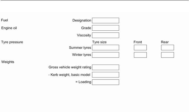
2Introduction
Introduction

Introduction 3
Vehicle specific data
Please enter your vehicle’s data on the previous page to keep it easily accessible.
Please refer to the sections «Service and maintenance», «Technical data», the vehicle’s identification plate and national registration documents.
Introduction
Your vehicle is a designed combination of advanced technology, safety, environmental friendliness and economy.
This Owner’s Manual provides you with all the necessary information to enable you to drive your vehicle safely and efficiently.
Make sure your passengers are aware of the possible risk of accident and injury which may result from improper use of the vehicle.
You must always comply with the specific laws and regulations of the country that you are in. These laws may differ from the information in this Owner’s Manual.
Disregarding the description given in this manual may affect your warranty.
When this Owner’s Manual refers to a workshop visit, we recommend your Opel Service Partner.
All Opel Service Partners provide first-class service at reasonable prices. Experienced mechanics trained by Opel work according to specific Opel instructions.
The customer literature pack should always be kept ready to hand in the vehicle.
Using this manual
●Thismanualdescribesalloptions and features available for this model. Certain descriptions, including those for display and menu functions, may not apply to your vehicle due to model variant, country specifications, special equipment or accessories.
●The»Inbrief»sectionwillgiveyou an initial overview.
●The table of contents at the beginning of this manual and within each section shows where the information is located.
●The index will enable you to search for specific information.
●ThisOwner’sManualdepictslefthand drive vehicles. Operation is similar for right-hand drive vehicles.
●The Owner’s Manual uses the engine identifier code. The corresponding sales designation and engineering code can be found in the section «Technical data».
●Directional data, e.g. left or right, or front or back, always relate to the direction of travel.
●Displays may not support your specific language.
●Display messages and interior labelling are written in bold letters.

4Introduction
Danger, Warnings and
Cautions
9 Danger
Text marked 9 Danger provides information on risk of fatal injury. Disregarding this information may endanger life.
9 Warning
Text marked 9 Warning provides information on risk of accident or injury. Disregarding this information may lead to injury.
Caution
Text marked Caution provides informationonpossibledamageto the vehicle. Disregarding this information may lead to vehicle damage.
Symbols
Page references are indicated with 3. 3 means «see page».
Page references and index entries refer to the indented headings given in the section table of content.
We wish you many hours of pleasurable driving.
Your Opel Team

Introduction 5

6In brief
In brief
Initial drive information
Vehicle unlocking
Press cto unlock the vehicle. Open the doors by pulling the handles.
Press P to unlock the tailgate only.
Tailgate
After unlocking, press the tailgate button and open the tailgate.
Radio remote control 3 22. Central locking system 3 24. Electronic key system 3 23. Load compartment 3 30.
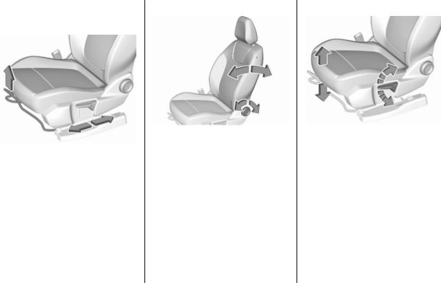
Seat adjustment
Longitudinal adjustment
Pull handle, slide seat, release handle.Trytomovetheseatbackand forth to ensure that the seat is locked in place.
Seat position 3 45.
Manual seat adjustment 3 46.
Backrests inclination
Turn handwheel. Do not lean on backrest when adjusting.
Seat position 3 45.
Manual seat adjustment 3 46.
Seat height
Lever pumping motion
|
up |
: |
seat higher |
|
down |
: |
seat lower |
Seat position 3 45.
Manual seat adjustment 3 46.
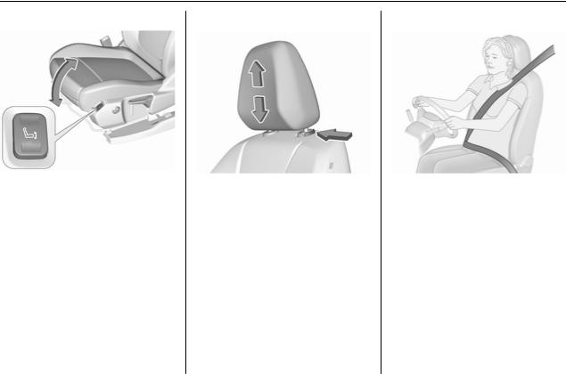
8In brief
Seat inclination
Press switch
|
top |
: |
front end higher |
|
bottom |
: |
front end lower |
Seat position 3 45.
Manual seat adjustment 3 46.
Head restraint adjustment |
Seat belt |
|
Press release button, adjust height, |
Pullouttheseatbeltandfasteninbelt |
|
engage. |
buckle. The seat belt must not be |
|
Head restraints 3 44. |
twisted and must fit close against the |
|
body. The backrest must not be tilted |
|
|
back too far (maximum approx. 25°). |
|
|
To unfasten belt, press red button on |
|
|
belt buckle. |
|
|
Seat position 3 45. |
|
|
Seat belts 3 51. |
|
|
Airbag system 3 54. |
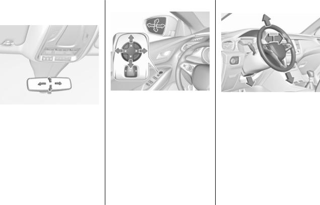
Mirror adjustment
Interior mirror
To adjust the mirror, move the mirror housing in the desired direction.
Manual anti-dazzle interior mirror 3 39.
Automatic anti-dazzle interior mirror 3 39.
Exterior mirrors
Select the relevant exterior mirror by pushing the mirror button to the left or right. Adjust respective mirror by the four-way control.
Convex mirrors 3 37. Electric adjustment 3 37. Folding mirrors 3 38. Heated mirrors 3 38.
Steering wheel adjustment
Unlock lever, adjust steering wheel, then engage lever and ensure it is fully locked. Do not adjust steering wheelunlessvehicleisstationaryand steering wheel lock has been released.
Seat position 3 45. Ignition positions 3 135.
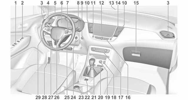
Instrument panel overview

|
1 |
Power windows |
40 |
13 |
Anti-theft alarm system |
||
|
2 |
Exterior mirrors ………………… |
37 |
status LED ……………………… |
35 |
||
|
3 |
Side air vents …………………. |
131 |
14 |
Central locking system ………. |
24 |
|
|
4 |
Turn lights, headlight |
15 |
Glovebox ………………………… |
68 |
||
|
flash, low / high beam, |
16 |
Controls for Info Display |
||||
|
high beam assist …………….. |
118 |
operation ……………………….. |
102 |
|||
|
Exit lighting ……………………. |
122 |
17 |
Climate control system …….. |
124 |
||
|
Parking lights …………………. |
119 |
18 |
USB charging port ……………. |
84 |
||
|
Buttons for Driver |
19 |
Power outlet …………………….. |
84 |
|||
|
20 |
Parking assist / Advanced |
|||||
|
Information Centre ………….. |
100 |
175 |
||||
|
5 |
Cruise control |
157 |
parking assist ………………… |
|||
|
Lane departure warning |
188 |
|||||
|
Speed limiter |
160 |
|||||
|
Eco button for stop-start |
||||||
|
Heated steering wheel |
79 |
|||||
|
system …………………………… |
139 |
|||||
|
6 |
Instruments ……………………… |
90 |
Electronic Stability Control |
|||
|
Driver Information Centre …. |
100 |
and Traction Control ……….. |
154 |
|||
|
7 |
Infotainment controls |
Sport mode ……………………. |
157 |
|||
|
8 |
Windscreen wiper and |
21 |
Manual transmission ………. |
150 |
||
|
washer, rear wiper and |
Automatic transmission |
147 |
||||
|
washer …………………………… |
80 |
|||||
|
9 |
Power button ………………….. |
136 |
22 |
Electric parking brake ……… |
151 |
|
|
10 |
Centre air vents ……………… |
131 |
23 |
Selective ride control ………. |
155 |
|
|
11 |
Hazard warning flashers …. |
118 |
24 |
Ignition switch ………………… |
135 |
|
|
12 |
Info Display …………………… |
102 |
25 |
Steering wheel adjustment . |
. 79 |
|
|
26 |
Horn ………………………………. |
80 |
|
27 |
Storage …………………………… |
68 |
|
28 |
Bonnet release lever ………. |
203 |
|
29 |
Light switch …………………… |
113 |
|
Headlight range |
||
|
adjustment ……………………. |
115 |
|
|
Front / rear fog lights ………. |
119 |
|
|
Instrument illumination ……. |
120 |
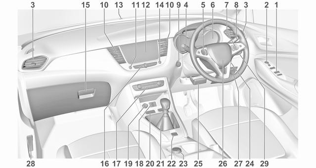
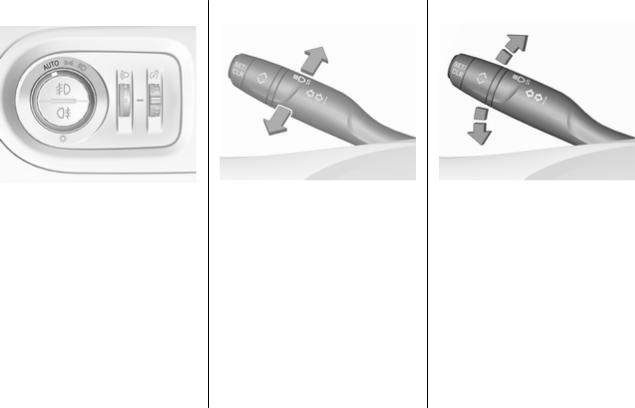
Exterior lighting
AUTO : automatic light control switches automatically between daytime running light and headlight
8 : sidelights
9 : headlights Automatic light control 3 114.
Fog lights
Press button in light switch: > : front fog lights
ø : rear fog light
Headlight flash and high beam |
Turn lights |
|
pull stalk |
: headlight flash |
stalk up : right turn light |
|
push stalk |
: high beam |
stalk down : left turn light |
|
High beam 3 114. |
Turn lights 3 118. |
|
|
High beam assist 3 115. |
Parking lights 3 119. |
|
|
Headlight flash 3 114. |
||
|
LED headlights 3 115. |
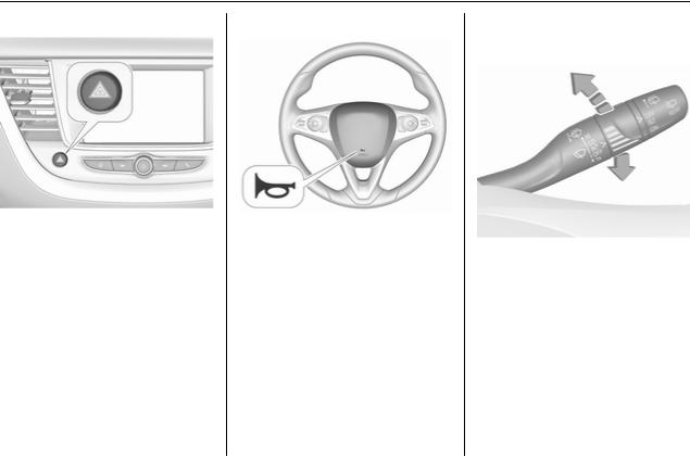
14 In brief
Hazard warning flashers |
Horn |
Washer and wiper systems |
Windscreen wiper |
|
Operated by pressing ¨. |
Press j. |
|
|
Hazard warning flashers 3 118. |
HI |
: fast |
|
LO |
: slow |
|
|
INT |
: interval wiping |
or
AUTO : automatic wiping with rain sensor
OFF : off
For single wipe when the wiper is off, press stalk down to position 1x.
Windscreen wiper 3 80.
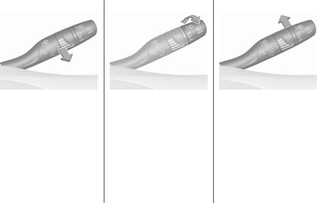
Windscreen washer
Pull stalk.
Windscreen washer system 3 80. Washer fluid 3 206.
Wiper blade replacement 3 208.
Rear window wiper
Turn outer cap to activate the rear window wiper:
|
OFF |
: off |
|
INT |
: intermittent operation |
|
ON |
: continuous operation |
Rear window washer
Push stalk.
Washer fluid is sprayed on the rear window and the wiper wipes a few times.
Rear window wiper / washer 3 82.

Climate control
Heated rear window
Heating and ventilation system, air conditioning system
The heating is operated by pressing b.
Electronic climate control system
The heating is operated by pressing b.
Heated rear window 3 41.
Heated exterior mirrors
Pressing b also activates the heated exterior mirrors.
Heated exterior mirrors 3 38.
Demisting and defrosting the windows
Heating and ventilation system, air conditioning system
●press à, the air distribution is directed towards the windscreen
●set temperature controller £ to warmest level
●switch on air conditioning A/C, if required
●set fan speed Z to highest level
●switch on heated rear window b

●switch on heated windscreen ,
●open side air vents as required and direct them towards the door windows
Heating and ventilation system 3 123.
Air conditioning system 3 124. Heated windscreen 3 42.
Electronic climate control system |
Electronic climate control system |
|
3 127. |
●press à, the LED in the button illuminates to indicate activation
●temperature and air distribution are set automatically and the fan runs at high speed
●switch on air conditioning by pressing A/C, if required
●switch on heated rear window b
●switch on heated windscreen ,
●to return to previous mode, press à again
●to return to automatic mode, press AUTO

Transmission
Manual transmission
To engage reverse on 6-speed transmission, depress the clutch pedal, pull the ring under the selector lever and move the selector lever quite to the left and front.
Manual transmission 3 150.
Automatic transmission
P : park position R : reverse
N : neutral mode D : automatic mode M : manual mode < : upshift
] : downshift
Automatic transmission 3 147.
Starting off
Check before starting off
●tyre pressure 3 221 and condition 3 257
●engine oil level and fluid levels 3 204
●all windows, mirrors, exterior lighting and number plates are free from dirt, snow and ice and are operational
●proper position of mirrors 3 37, seats 3 45 and seat belts
3 52
●brake function at low speed, particularly if the brakes are wet
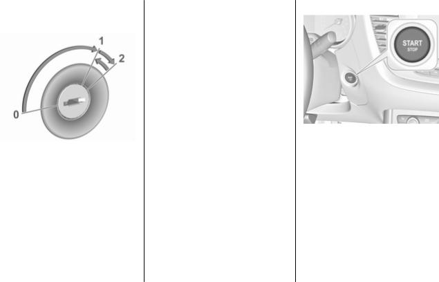
Starting the engine
Ignition switch
●turn key to position 1
●move the steering wheel slightly toreleasethesteeringwheellock
●manual transmission: operate clutch and brake pedal
●automatic transmission: operate brake pedal and move selector lever to P or N
●do not operate accelerator pedal
●turn key to position 2 and release after engine has been started
Diesel engine starts after control indicator !for preheating extinguishes.
Starting the engine 3 138.
Start power button
●manual transmission: operate clutch and brake pedal
●automatic transmission: operate brake pedal and move selector lever to P or N
●do not operate accelerator pedal
●press Start/Stop button
●release button after starting procedure begins

Stop-start system
If the vehicle is at a low speed or at a standstill and certain conditions are fulfilled, an Autostop is activated.
An Autostop is indicated by control indicator D.
Manual transmission: to restart the engine, depress the clutch pedal again. Control indicator D
extinguishes.
Automatic transmission: to restart the engine, release the brake pedal. Control indicator D extinguishes.
Stop-start system 3 139.
Parking
9Warning
●Do not park the vehicle on an easily ignitable surface. The high temperature of the exhaustsystemcouldignitethe surface.
●Always apply the parking brake.
●If the vehicle is on a level surface or uphill slope, engage first gear or set the selector lever to position P. On an uphill slope, turn the front wheels away from the kerb.
If the vehicle is on a downhill slope, engage reverse gear or settheselectorlevertoposition P. Turn the front wheels towards the kerb.
●Close the windows.
●Switch off the engine.
●Remove the ignition key from the ignition switch or switch off ignition on vehicles with power
button. Turn the steering wheel until the steering wheel lock is felt to engage.
●Lock the vehicle with eon the radio remote control.
Activate the anti-theft alarm system 3 35.
●The engine cooling fans may run after the engine has been switched off 3 203.
Caution
After running at high engine speeds or with high engine loads, operate the engine briefly at a low load or run in neutral for
approx. 30 seconds before switching off, in order to protect the turbocharger.
Keys, locks 3 21.
Laying-up the vehicle for a long period of time 3 202.

Keys, doors and windows |
21 |
|
Keys, doors and |
|
|
windows |
|
|
Keys, locks …………………………….. |
21 |
|
Keys …………………………………… |
21 |
|
Radio remote control …………….. |
22 |
|
Electronic key system ……………. |
23 |
|
Central locking system ………….. |
24 |
|
Automatic locking …………………. |
28 |
|
Child locks …………………………… |
29 |
|
Doors ……………………………………. |
30 |
|
Load compartment ……………….. |
30 |
|
Vehicle security ………………………. |
35 |
|
Anti-theft locking system ……….. |
35 |
|
Anti-theft alarm system ………….. |
35 |
|
Immobiliser ………………………….. |
37 |
|
Exterior mirrors ………………………. |
37 |
|
Convex shape ……………………… |
37 |
|
Electric adjustment ……………….. |
37 |
|
Folding mirrors …………………….. |
38 |
|
Heated mirrors ……………………… |
38 |
|
Interior mirrors ……………………….. |
39 |
|
Manual anti-dazzle ……………….. |
39 |
|
Automatic anti-dazzle ……………. |
39 |
|
Windows ……………………………….. |
39 |
|
Windscreen …………………………. |
39 |
|
Power windows ……………………. |
40 |
|
Heated rear window ……………… |
41 |
|
Heated windscreen ……………….. |
42 |
|
Sun visors ……………………………. |
42 |
|
Roller blinds …………………………. |
42 |
|
Roof ……………………………………… |
43 |
|
Glass panel …………………………. |
43 |
Keys, locks
Keys
Caution
Donotattachheavyorbulkyitems to the ignition key.
Replacement keys
The key number is specified on a detachable tag.
The key number must be quoted when ordering replacement keys as it is a component of the immobiliser system.
Locks 3 236. Central locking 3 24.
Starting the engine 3 138. Radio remote control 3 22. Electronic key 3 23.
The code number of the adapter for the locking wheel nuts is specified on a card. It must be quoted when ordering a replacement adapter.
Wheel changing 3 228.
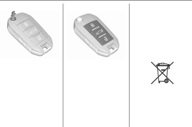
22 Keys, doors and windows
Key with foldaway key section
Press button to extend. To fold the key, first press the button.
Radio remote control
Enables operation of the following functions via the use of the remote control buttons:
●central locking system 3 24
●anti-theft locking system 3 35
●anti-theft alarm system 3 35
●tailgate unlocking and opening
●power windows 3 40
●mirrors folding 3 38
The remote control has a range of up to 100 m, but may also be much less due to external influences. The hazard warning flashers confirm operation.
Handle with care, protect from moisture and high temperatures and avoid unnecessary operation.
Replacing battery in radio remote control
Replace the battery as soon as the range reduces.
Batteries do not belong in household waste. They must be disposed of at an appropriate recycling collection point.
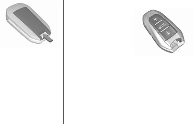
|
Keys, doors and windows |
23 |
1.Remove the back cover from the remote control.
2.Extract the flat battery from its location.
3.Replace battery with a battery of the same type. Pay attention to the installation position.
4.Clip the back cover in place.
Fault
If the central locking system cannot be operated with the radio remote control, the cause may be one of the following:
●Fault in radio remote control.
●Electronic key is out of reception range.
●The battery voltage is too low.
●Overload of the central locking system by operating at frequent intervals, the power supply is interrupted for a short time.
●Interference from higher-power radio waves from other sources.
Manual unlocking 3 24.
Electronic key system
Enables a keyless operation of the following functions:
●central locking system 3 24
●power tailgate 3 30
●ignition switching on and starting the engine 3 138
Theelectronickeysimplyneedstobe on the driver’s person.
Additionally, the electronic key includes the functionality of the radio remote control 3 22.
Handle with care, protect from moisture and high temperatures and avoid unnecessary operation.

24 Keys, doors and windows
Replacing battery in electronic key
Replace the battery as soon as the system no longer operates properly or the range is reduced. The need for battery replacement is indicated by a message in the Driver Information Centre 3 104.
Batteries do not belong in household waste. They must be disposed of at an appropriate recycling collection point.
1.Remove the cover.
2.Extract the flat battery from its location.
3.Replace battery with a battery of the same type. Pay attention to the installation position.
4.Clip the cover in place.
Fault
If the central locking cannot be operated or the engine cannot be started, the cause may be one of the following:
●Fault in electronic key.
●Electronic key is out of reception range.
●The battery voltage is too low.
●Overload of the central locking system by operating at frequent intervals, the power supply is interrupted for a short time.
●Interference from higher-power radio waves from other sources.
To rectify the cause of the fault, change the position of the electronic key.
Manual unlocking 3 24.
Central locking system
Unlocks and locks doors, load compartment and fuel filler flap.
A pull on an interior door handle unlocks the respective door. Pulling thehandleoncemoreopensthedoor.
Note
In the event of an accident in which airbags or belt pretensioners are deployed, the vehicle is automatically unlocked.
Note
A short time after unlocking with the remote control the doors are locked automatically if no door has been
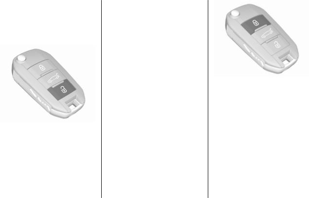
|
Keys, doors and windows |
25 |
opened. A precondition is that the setting is activated in the vehicle personalisation 3 105.
Remote control operation
Unlocking
Press O.
Unlocking mode can be set in the vehicle personalisation menu in the Info Display. Two settings are selectable:
●All doors, load compartment and fuel filler flap will be unlocked by pressing O once.
●Only the driver’s door and fuel filler flap will be unlocked by pressing O once. To unlock all
doors, load compartment and fuel filler flap, press O twice.
Select the relevant setting in the Vehicle personalisation.
Vehicle personalisation 3 105.
Unlocking the tailgate
Press P longer to unlock the tailgate only.
Unlocking and opening the tailgate 3 30.
Locking
Close doors, load compartment and fuel filler flap.
Press N.
If the driver’s door is not closed properly, the central locking system will not work.
Confirmation
Operation of the central locking system is confirmed by the hazard warning flashers. A precondition is that the setting is activated in the vehicle personalisation 3 105.
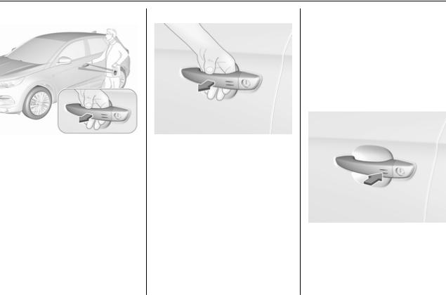
26 Keys, doors and windows
Electronic key system operation
The electronic key must be outside the vehicle, within a range of approx. 1 m of the relevant door side.
Unlocking
Pass a hand behind the door handle of one of the front doors to unlock the vehicle or press the tailgate button.
Unlocking mode can be set in the vehicle personalisation menu in the Info Display. Two settings are selectable:
●Only the driver’s door and fuel filler flap will be unlocked by passing a hand behind the driver’s door handle.
●All doors, load compartment and fuel filler flap will be unlocked by passing a hand behind the passenger’s door handle or by pressing the tailgate button.
●Only the tailgate will be unlocked by pressing the tailgate button.
Vehicle personalisation 3 105. Locking
Press with a finger or thumb on one of the door handles (at the markings) or press the tailgate button.
All doors, load compartment and fuel filler flap will be locked.
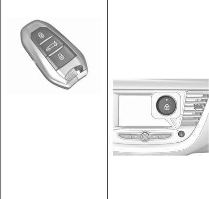
|
Keys, doors and windows |
27 |
The system locks if any door has been opened and all doors are now closed.
If the driver’s door is not closed properly,theelectronickeyremainsin the vehicle or the ignition is not off, locking will not be permitted and a warning chime sounds.
Keep the hand behind the door handle or keep the tailgate button pressed to close the windows.
If there have been two or more electronic keys in the vehicle and the ignitionwasononce,thedoorswillbe locked even if just one electronic key is taken out of the vehicle.
Unlocking and opening the tailgate
The tailgate can be unlocked and opened hands-free by pushing the touchpad switch under the tailgate mouldingwhentheelectronickeyisin range. The doors remain locked.
Load compartment 3 30.
Operation with buttons on the electronic key
The central locking system can also be operated with the buttons on the electronic key.
Press O to unlock. Press N to lock.
Press P longer to unlock and open only the power tailgate.
Remote control operation 3 24.
Confirmation
Operation of central locking system is confirmed by the hazard warning flashers. A precondition is that the setting is activated in the vehicle personalisation 3 105.
Central locking button
Locks or unlocks all doors, the load compartment and fuel filler flap from inside the passenger compartment.
PressQ tolock.TheLEDinthebutton illuminates.
Press Q again to unlock. The LED in the button extinguishes.
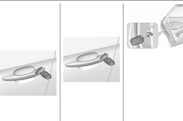
28 Keys, doors and windows
Operation with the key in case of a central locking system fault
In case of a fault, e.g. vehicle battery or remote control / electronic key battery is discharged, the driver’s door can be locked or unlocked with the mechanical key.
Manual unlocking
Electronic key: press and hold the latch to extract the integral key.
Manually unlock the driver’s door by inserting and turning the key in the lock cylinder.
The other doors can be opened by pulling the interior handle. The load compartment and fuel filler flap will possibly not be unlocked.
By switching on the ignition, the antitheft locking system is deactivated.
Manual locking
Manually lock the driver’s door by inserting and turning the key in the lock cylinder.
To lock the other doors, remove the black cover by using a key.
Insert key carefully and move to the inner side of the door without turning the key.
Remove key and attach black cover.
The fuel filler flap and tailgate are possibly not locked.
Automatic locking
Automatic locking after driving off
This system allows automatic locking of the doors and tailgate as soon as the speed of the vehicle exceeds a certain speed.

|
Keys, doors and windows |
29 |
If one of the doors or the tailgate is open, the automatic central locking does not take place. This is signalled by the sound of the locks rebounding, accompanied by illumination of h in
the instrument cluster, an audible signal and the display of an alert message.
This function can be activated or deactivated at any time. With the ignition on, press Q until an audible
signal starts and a corresponding message is displayed.
The state of the system stays in memory when switching off the ignition.
Automatic relock after unlocking
This feature automatically locks all doors, load compartment and fuel filler flap a short time after unlocking with the remote control or electronic key, provided no door has been opened.
Child locks
9 Warning
Use the child locks whenever children are occupying the rear seats.
Mechanical child locks
Turntheredchildlockinthereardoor to the horizontal position by using a key. The door cannot be opened from the inside.
To deactivate, turn the child lock to the vertical position.

30 Keys, doors and windows
Electric child locks
Remotelyoperatedsystemtoprevent opening of the rear doors via the interior door handles and the use of the rear power windows.
Switching on
Press R. The indicator lamp in the
button comes on, accompanied by a confirmation message. This indicator lamp remains on until the child lock is switched off.
Switching off
Press R again. The indicator lamp on
button goes off, accompanied by a confirmation message. This indicator lamp remains on while child lock is switched on.
Doors
Load compartment
Tailgate
Opening
After unlocking, press the tailgate button and open the tailgate.

|
Keys, doors and windows |
31 |
Closing
Use the interior handle.
Do not push the touchpad switch whilst closing as this will unlock the tailgate again.
Central locking system 3 24.
Power tailgate
9 Warning
Take care when operating the power tailgate. Risk of injury, particularly to children.
Keep a close watch on the movable tailgate when operating. Ensure that nothing becomes trapped during operating and no one is standing within the moving area.
The power tailgate can be operated by:
●Pressing P longer on the electronic key.
●Hands-freeoperationwithmotion sensor below the rear bumper.
●ThetailgatebuttonandT inthe open tailgate.
On vehicles with automatic transmission, the tailgate can only be operated when the vehicle is stationary and automatic transmission in P.
The turn signal lights flash and a chime sounds when the power tailgate is operating.
Note
Operating the power tailgate does not operate the central locking system.Toopenthetailgatewiththe button on the electronic key, or with
the tailgate button or via hands-free operation, it is not necessary to unlock the vehicle. A precondition is that the electronic key is outside the vehicle, within a range of approx. 1 m of the tailgate.
Donotleavetheelectronickeyinthe load compartment.
Lockthevehicleafterclosingifitwas unlocked previously.
Central locking system 3 24. Operation with the electronic key
PressP longertoopenorclosethe
tailgate.

32 Keys, doors and windows
Hands-free operation with motion sensor below the rear bumper
Toopenorclosethetailgatemovethe foot below the rear bumper back and forth in the area below the number plate. The key must be within a range of 1 m. Do not hold the foot longer or movetooslowbelowthebumper.The electronic key must be outside the vehicle, within a range of approx.
1 m of the tailgate.
Activation or deactivation of handsfree operation can be set in the menu Settings I Vehicle in the Info Display.
Info Display 3 102.
Vehicle personalisation 3 105.
9 Danger
Do not touch any vehicle parts below the vehicle during handsfree operation. There is a risk of injury from hot engine parts.
Automatic locking after hands-free operation
Press button S in the open tailgate,
the whole vehicle will be locked after hands-free closing of the tailgate.
Operation with the tailgate button
To open the tailgate, press the tailgate button until the tailgate starts to move. If the vehicle is locked, the electronic key must be outside the vehicle, within a range of approx.
1 m of the tailgate.

|
Keys, doors and windows |
33 |
To close, press T in the open
tailgate until the tailgate starts to move.
Stop or change direction of movement
Stop movement of the tailgate immediately:
●press P longer on the electronic key, or
●press the tailgate button, or
●press T on the open tailgate
Pressing one of the switches again will reverse the direction of movement.
Adjust reduced opening height
1.Open power tailgate with any operation switch.
2.Stop movement at the desired height by pressing T. If
required, manually move the stopped tailgate to the desired position.
3.Press and hold the button T on
the inside of the open tailgate for 3 seconds.
Note
Adjusting opening height should be programmed at ground level.
A chime sound indicates the new setting and the turn signal lights will flash.Thereducedheightcanonlyset at an opening angle of above 30°.
To delete reduced height position, open tailgate in half position and press T for 3 seconds.
The tailgate can only be held open if a minimum height is exceeded (minimum opening angle from 30°). The opening height cannot be programmed below that height.
Safety function
If the power tailgate encounters an obstacle during opening or closing, the direction of movement will automatically be reversed slightly. Multiple obstacles in one power cycle will deactivate the function. In this case, close or open the tailgate manually.
The power tailgate has pinch sensors on the side edges. If the sensors detectobstaclesbetweentailgateand chassis, the tailgate will open, until it is activated again or closed manually.
The safety function is indicated by a warning chime.

34 Keys, doors and windows
Remove all obstacles before resuming normal power operation.
If the vehicle is equipped with factoryfitted towing equipment and a trailer is electrically connected, the power tailgate can only be opened with the tailgate button or closed with T in
the open tailgate. Ensure that there are no obstacles in the moving area.
Overload
If the power tailgate is repeatedly operated at short intervals, the function is disabled for some time. Move tailgate manually into end position to reset the system.
Initialising power tailgate
If the power tailgate cannot be operated automatically (e.g. after disconnecting the vehicle battery), a warning message is displayed in the Driver Information Centre.
Activate electronics as follows:
1.Open tailgate manually.
2.Close tailgate manually.
3.Switch on ignition.
Seek the assistance of a workshop if the problem is not solved.
General hints for operating tailgate
9 Danger
Do not drive with the tailgate open or ajar, e.g. when transporting bulky objects, since toxic exhaust gases, which cannot be seen or smelled, could enter the vehicle. This can cause unconsciousness and even death.
Caution
Before opening the tailgate, check overhead obstructions, e.g. a garage door, to avoid damage to the tailgate. Always check the movingareaaboveandbehindthe tailgate.
Note
The installation of certain heavy accessories onto the tailgate may affect its ability to remain open.
Note
The operation of the power tailgate is disabled under low vehicle battery conditions. In this case, the tailgate may not even by manually operable.
Note
With the power tailgate disabled and all doors unlocked, the tailgate can only be operated manually. In this event, manually closing the tailgate requires significantly greater force.
Note
At low outside temperatures the tailgate may not open fully by itself. In this case lift the tailgate manually to its normal end position.

|
Keys, doors and windows |
35 |
Vehicle security
Anti-theft locking system
9 Warning
Do not use the system if there are people in the vehicle! The doors cannot be unlocked from the inside.
The system deadlocks all the doors. All doors must be closed otherwise the system cannot be activated.
Unlocking the vehicle disables the mechanical anti-theft locking system. This is not possible with the central locking button.
Activating
Press N on the radio remote control twice within 5 seconds.
Anti-theft alarm system
The anti-theft alarm system is combined with the anti-theft locking system.
It monitors:
●doors, tailgate, bonnet
●passenger compartment including adjoining load compartment
●vehicle inclination, e.g. if it is raised
●ignition
Activation
All doors, the load compartment and the engine compartment must be closed and the electronic key must not remain in the vehicle.
●Radio remote control: selfactivated 45 seconds after locking the vehicle by pressing e once.
●Electronic key system: selfactivated 45 seconds after locking the vehicle by pressing with a finger or thumb on one of the front door handles at the markings.
If a door, the tailgate or the bonnet is not properly closed, the vehicle is not locked. However, the anti-theft alarm is self-activated after 45 seconds.

36 Keys, doors and windows
Note
Changes to the vehicle interior such as the use of seat covers and open windows, could impair the function of passenger compartment monitoring.
Activation without monitoring of passenger compartment and vehicle inclination
Switch off the monitoring of passenger compartment and vehicle inclination when animals are being left in the vehicle, because of high volume ultrasonic signals or
movements triggering the alarm. Also switch off when the vehicle is on a ferry or train.
1.Close tailgate, bonnet, windows.
2.Switch off ignition and press o
within 10 secondsuntil the LED in the button o illuminates.
3.Close doors.
4.Activate the anti-theft alarm system.
Indication
LED in the o button flashes if the
anti-theft alarm system is activated. The hazard warning lights illuminates for a few seconds.
Deactivation
Radio remote control: Unlocking the vehicle by pressing cdeactivates the anti-theft alarm system.
Electronic key system: Unlocking the vehiclebypressingononeofthefront door handles at the markings deactivates the anti-theft alarm system.
The electronic key must be outside the vehicle, within a range of approx. 1 m of the relevant door side.
The system is not deactivated by unlocking the driver’s door with the key or with the central locking button in the passenger compartment.
The hazard warning lights flash for a few seconds.

|
Keys, doors and windows |
37 |
Alarm
When triggered, the alarm siren sounds and the hazard warning lights flash simultaneously. The number and duration of alarm signals are stipulated by legislation.
The anti-theft alarm system can be deactivated by pressing c, by pressing on one of the front door handles at the markings with electronic key system or switching on the ignition.
Atriggeredalarm,whichhasnotbeen interrupted by the driver, will be indicated by the LED in the button o. The LED will flash quickly the
next time the vehicle is unlocked with the radio remote control.
If the battery has been reconnected (e.g.aftermaintenancework),waitfor 10 minutes to restart the engine.
Fault
If the LED in the button o
illuminates permanently when switching on the ignition, seek the assistance of a workshop.
Locking the vehicle without activation of the anti-theft alarm
Lock the vehicle by locking the driver’s door with the integral key.
Immobiliser
The system is part of the ignition switch and checks whether the vehicle is allowed to be started with the key being used.
The immobiliser is activated automatically after the key has been removed from the ignition switch.
Note
Radio Frequency Identification (RFID) tags may cause interference with the key. Do not have it placed near the key when starting the vehicle.
Note
The immobiliser does not lock the doors. Always lock the vehicle after leavingit3 24andswitchontheanti-
theft alarm system 3 35.
Exterior mirrors
Convex shape
The shape of the mirror makes objects appear smaller, which will affect the ability to estimate distances.
Side blind spot alert 3 182.
Electric adjustment
Select the relevant exterior mirror by pushing the mirror button to the left or right.
Then swivel the control to adjust the mirror.

38 Keys, doors and windows
Folding mirrors
For pedestrian safety, the exterior mirrors will swing out of their normal mounting position if they are struck with sufficient force. Reposition the mirror by applying slight pressure to the mirror housing.
Electric folding
Pull mirror button rearwards. Both exterior mirrors will fold.
Pull mirror button rearwards again to return both exterior mirrors to their original position.
If an electrically folded mirror is manually extended, pulling mirror button rearwards will only electrically extend the other mirror.
Heated mirrors
Operated by pressing b.
Heating works with the engine running and is switched off automatically after a short time.
Heated rear window 3 41.

|
Keys, doors and windows |
39 |
Interior mirrors
Manual anti-dazzle
To reduce dazzle, adjust the lever on the underside of the mirror housing.
Automatic anti-dazzle
Dazzle from following vehicles is automatically reduced, when driving in the dark.
Windows
Windscreen
Windscreen stickers
Do not attach stickers such as toll road stickers or similar on the windscreen in the area of the interior mirror. Otherwise the detection zone of the sensor and the view area of the camerainthemirrorhousingcouldbe restricted.
Windscreen replacement
Caution
If the vehicle has a front-looking camera sensor for the driver assistance systems, it is very important that any windscreen replacement is performed accurately according to Opel specifications. Otherwise, these systems may not work properly and there is a risk of unexpected behaviour and / or messages from these systems.

40 Keys, doors and windows
Power windows
9 Warning
Take care when operating the power windows. Risk of injury, particularly to children.
If there are children on the rear seats, switch on the child safety system for the power windows.
Keep a close watch on the windows when closing them. Ensure that nothing becomes trapped in them as they move.
Switch on ignition to operate power windows.
Operate the switch for the respective window by pushing to open or pulling to close.
Pushing or pulling gently to the first detent: window moves up or down as long as the switch is operated.
Pushingorpullingfirmlytothesecond detent then releasing: window moves up or down automatically with safety function enabled. To stop movement, operate the switch once more in the same direction.
Safety function
If the window glass encounters resistance above the middle of the window during automatic closing, it is immediately stopped and opened again.
Override safety function
In the event of closing difficulties due to frost or the like, switch on the ignition,thenpulltheswitchtothefirst detent and hold. The window moves up without safety function enabled. To stop movement, release the switch.
Child safety system for rear windows
Press V to deactivate rear door
power windows; the LED illuminates. To activate, press V again.
Operating windows from outside
The windows can be operated remotely from outside the vehicle.

|
Keys, doors and windows |
41 |
Press and hold eto close windows.
Release button to stop window movement.
If the windows are fully closed, the hazard warning lights will flash twice.
Overload
If the windows are repeatedly operated within short intervals, the window operation is disabled for some time.
Initialising the power windows
If the windows cannot be closed automatically (e.g. after disconnecting the vehicle battery), a warning message is displayed in the Driver Information Centre.
Vehicle messages 3 104.
Activate the window electronics as follows:
1.Close doors.
2.Switch on ignition.
3.Pull switch until the window is closed and keep pulling for additional 2 seconds.
4.Push switch until the window is completely open and keep pushing for additional 2 seconds.
5.Repeat for each window.
Heated rear window
Operatedbypressingb togetherwith heated exterior mirrors.
Heating works with the engine running and is switched off automatically after a short time.
Dependingonclimatecontrolsystem, b is located at a different position.
Vehicles with heating and ventilation system or air conditioning system

42 Keys, doors and windows
Vehicles with electronic climate control system
Heated windscreen
Operated by pressing ,. LED in button illuminates.
Heating works with the engine running and is switched off automatically after a short time.
Depending on climate control system, , is located at a different
position.
Vehicles with electronic climate control system
Vehicles with air conditioning system
Sun visors
The sun visors can be folded down or swivelled to the side to prevent dazzling.
If the sun visors have integral mirrors, the mirror covers should be closed when driving.
A ticket holder is located on the backside of the sun visor.
Roller blinds
To reduce sunlight at the second row seats, pull the blind upwards using thegripandengageitatthetopofthe door frame.

|
Keys, doors and windows |
43 |
Roof
Glass panel
Sunblind
Press Ngently to the first detent at the rear: the sunblind is opened as long as the switch is operated.
Press Nfirmly to the second detent and then release at the rear: the sunblind is opened as long as the switch is operated.
Press Ngently to the first detent at the front: the sunblind is closed as long as the switch is operated.
Press Nfirmly to the second detent and then release at the front: the sunblind is closed as long as the switch is operated.
Safety function
If the sunblind encounters resistance during automatic closing, it is immediately stopped and opened again.
Function standby
In ignition switch position 1 the sunblind is operational 3 135.
Initialising after a power failure
After a power failure, it may only be possible to operate the sunblind to a limited extent. Initialise the system as follows:
1.Turn key in ignition switch to position 1.
2.Press Ntwice gently to the first detent at the rear, the sunblind opens slightly.
3.Immediately press Ntwice gently to the first detent at the front, the sunblind closes slightly.
After step 3 the sunblind is in initialising mode without safety function.
4.Press Ngently to the first detent at the rear until the sunblind is completely opened.
5.Press Ngently to the first detent at the front until the sunblind is completely closed.
After this procedure, the sunblind is initialised with safety function activated.
When Nis pressed firmly to the second detent during initialising, the procedure is cancelled.

44 Seats, restraints
Seats, restraints |
|
|
Head restraints ………………………. |
44 |
|
Front seats …………………………….. |
45 |
|
Seat position ………………………… |
45 |
|
Manual seat adjustment ………… |
46 |
|
Power seat adjustment ………….. |
48 |
|
Armrest ……………………………….. |
50 |
|
Heating ……………………………….. |
50 |
|
Ventilating ……………………………. |
50 |
|
Rear seats …………………………….. |
51 |
|
Armrest ……………………………….. |
51 |
|
Heating ……………………………….. |
51 |
|
Seat belts ………………………………. |
51 |
|
Three-point seat belt …………….. |
52 |
|
Airbag system ………………………… |
54 |
|
Front airbag system ………………. |
58 |
|
Side airbag system ……………….. |
58 |
|
Curtain airbag system …………… |
59 |
|
Airbag deactivation ……………….. |
59 |
|
Child restraints ……………………….. |
61 |
|
Child restraint systems ………….. |
61 |
|
Child restraint installation |
|
|
locations …………………………….. |
64 |
Head restraints
Position
9 Warning
Only drive with the head restraint set to the proper position.
The upper edge of the head restraint should be at upper head level. If this is not possible for extremely tall people, set to highest position, and settolowestpositionforsmallpeople.
Adjustment
Head restraints on front seats
Height adjustment
Pull the head restraint upwards or press the catch to release and push the head restraint downwards.

Head restraints on rear seats
Height adjustment
Pull the head restraint upwards or press the catch to release and push the head restraint downwards.
Removal
Press catch, pull the respective head restraint upwards and remove.
Front seats
Seat position
9 Warning
Only drive with the seat correctly adjusted.
9 Warning
Neveradjustseatswhiledrivingas they could move uncontrollably.
9 Danger
Do not sit closer than 25 cm to the steering wheel, to permit safe airbag deployment.
9 Warning
Never store any objects under the seats.
●Sit with buttocks as far back against the backrest as possible. Adjust the distance between the seat and the pedals so that legs areslightlyangledwhenpressing the pedals. Slide the front passenger seat as far back as possible.
●Set seat height high enough to have a clear field of vision on all sides and of all display instruments. There should be at least one hand of clearance between head and the roof frame. Your thighs should rest lightly on the seat without pressing into it.

46 Seats, restraints
●Sit with shoulders as far back against the backrest as possible. Set the backrest rake so that it is possible to easily reach the steering wheel with arms slightly bent. Maintain contact between shoulders and the backrest when turning the steering wheel. Do not angle the backrest too far back. We recommend a maximum rake of approx. 25°.
●Adjust seat and steering wheel in a way that the wrist rests on top of the steering wheel while the arm is fully extended and shoulders are on the backrest.
●Adjust the steering wheel 3 79.
●Adjust the head restraint 3 44.
●Adjust the height of the seat belt 3 52.
●Adjust the thigh support so that there is a space approx. two fingers wide between the edge of the seat and the hollow of the knee.
●Adjust the lumbar support so that it supports the natural shape of the spine.
Manual seat adjustment |
Backrest inclination |
Drive only with engaged seats and backrests.
Longitudinal adjustment
Turn handwheel. Do not lean on backrest when adjusting.
Pull handle, slide seat, release handle.Trytomovetheseatbackand forth to ensure that the seat is locked in place.

Seat height |
Seat inclination |
|
Lever pumping motion |
Press switch |
||
|
up |
: seat higher |
at the rear |
: front end higher |
|
down |
: seat lower |
at the front |
: front end lower |
Lumbar support
Adjust lumbar support using the fourway switch to suit personal requirements.
Moving support up and down: push switch up or down.
Increasing and decreasing support: push switch forwards or backwards.

48 Seats, restraints
Adjustable thigh support
Pull the lever and slide the thigh support.
Power seat adjustment
9 Warning
Care must be taken when operating the power seats. There is a risk of injury, particularly for children. Objects could become trapped.
Keep a close watch on the seats when adjusting them. Vehicle passengers should be informed accordingly.
Longitudinal adjustment
Move switch forwards / backwards.
Seat height
Move switch upwards / downwards.
Seat inclination
 Loading…
Similar Devices: A-Class, 2003 XC90, 206
-
2 0 0 1 VOLVOS80This manual deals with the operation and care of your Volvo.This manual deals with the operation and care of your VolvoWelcome to the world-wide family of Volvo owners. We trust that you will enjoy many years of safe driving in yourVolvo, an automobile designed with your safety and comfort in mind. To help ensure your satisfaction with thisve …
2001 S80, 106
-
All information in this Owner’s Manual is current at the time of publication. However, HYUNDAI reserves the right to make changes at any time so that our policy of continual product improvement may be carried out.This manual applies to all models of this vehicle and includes descriptions and explanations of optional as well as standard equipment.As a resul …
Kona, 561
-
Kia, THE COMPANYEnjoy your vehicle and Kia’s “Family-like Care” experience!Thank you for becoming the owner of a new Kia vehicle.As a global car manufacturer focused on building high-quality, value formoney prices, Kia Motors is dedicated to providing you with a customerservice experience that exceeds your expectations.At all of our Kia dealerships you …
Stonic 2019, 611
-
Introduction 4Instrument Cluster 10Warning and control lights 10Gauges 13Entertainment Systems 15AM/FM stereo with CD 15AM/FM stereo cassette with CD 18AM/FM stereo with cassette and in-dash six CD 24Navigation system 30Climate Controls 92Dual automatic temperature control 92Rear window defroster 95Lights 96Headlamps 96Turn signal control 99Bulb replacement …
Town Car 2006, 320
-
2About EyeSightEyeSight is a driving support system that uses a range of functions to assist the driver inmaking decisions in order to provide for more safe and comfortable driving and to reducedriver fatigue. EyeSight makes use of original stereo cameras designed by SUBARU. TwoCCD (Charge Coupled Device) cameras are used to process stereo images and identif …
EyeSight, 19
-
Congratulations on your purchase of a Chevrolet Corvette. Please read this information and your OwnerManual to ensure an outstanding ownership experience. Note that your vehicle may not include all thefeatures described in this booklet. Keep this booklet with your Owner Manual for easy reference.DRIVER INFORMATIONInstrument Panel . . . . . . . . . . . . . . …
2008 Corvette, 20