

Version 2.00
Revision B
June 2009
|
Table of Contents |
|
|
Introduction…………………………………………………………………………………………………………………………………………… |
1 |
|
Legal Notices………………………………………………………………………………………………………………………………. |
1 |
|
About the EZ−Guide 250 System…………………………………………………………………………………………………… |
1 |
|
Related Information……………………………………………………………………………………………………………………… |
2 |
|
Technical Support………………………………………………………………………………………………………………………… |
2 |
|
About the Lightbar………………………………………………………………………………………………………………………………… |
3 |
|
What’s in the EZ−Guide 250 Box…………………………………………………………………………………………………… |
3 |
|
Parts of the Lightbar……………………………………………………………………………………………………………………… |
3 |
|
How the Buttons Work…………………………………………………………………………………………………………………. |
5 |
|
Optional Accessories…………………………………………………………………………………………………………………….. |
7 |
|
Upgrades…………………………………………………………………………………………………………………………………….. |
7 |
|
Fuse Information………………………………………………………………………………………………………………………….. |
7 |
|
Serial Port Information………………………………………………………………………………………………………………….. |
7 |
|
Installation…………………………………………………………………………………………………………………………………………….. |
9 |
|
Step 1: Installing the Antenna………………………………………………………………………………………………………… |
9 |
|
Step 2. Attaching the Lightbar Cables…………………………………………………………………………………………….. |
9 |
|
Step 3: Turning on the Lightbar……………………………………………………………………………………………………. |
10 |
|
Turning off the lightbar……………………………………………………………………………………………………………….. |
10 |
|
Connecting a Coverage Switch…………………………………………………………………………………………………….. |
11 |
|
Getting Started…………………………………………………………………………………………………………………………………….. |
12 |
|
Quick Start Wizard……………………………………………………………………………………………………………………… |
12 |
|
Items on the Main Guidance Screen……………………………………………………………………………………………… |
13 |
|
Status Indicators…………………………………………………………………………………………………………………………. |
14 |
|
View Modes………………………………………………………………………………………………………………………………. |
14 |
|
User Modes……………………………………………………………………………………………………………………………….. |
15 |
|
Changing the User Mode…………………………………………………………………………………………………………….. |
15 |
|
Changing the Backlight Brightness……………………………………………………………………………………………….. |
15 |
|
Changing the LED Brightness……………………………………………………………………………………………………… |
16 |
|
Getting GPS Corrections……………………………………………………………………………………………………………… |
16 |
|
Easy Mode Guidance……………………………………………………………………………………………………………………………. |
17 |
|
Introduction to Guidance…………………………………………………………………………………………………………….. |
17 |
|
Following Guidance……………………………………………………………………………………………………………………. |
18 |
|
Guidance Patterns………………………………………………………………………………………………………………………. |
19 |
|
Getting Guidance……………………………………………………………………………………………………………………….. |
31 |
|
Coverage Logging………………………………………………………………………………………………………………………. |
33 |
|
Creating straight sections on Headland or Curve swaths………………………………………………………………….. |
34 |
|
Pause / Resume Icon…………………………………………………………………………………………………………………… |
34 |
|
Advanced Mode Guidance……………………………………………………………………………………………………………………. |
36 |
|
Resetting Guidance…………………………………………………………………………………………………………………….. |
36 |
|
Creating a New Field………………………………………………………………………………………………………………….. |
36 |
|
Creating a new line…………………………………………………………………………………………………………………….. |
38 |
|
Selecting (Loading) an AB Line…………………………………………………………………………………………………… |
40 |
|
Selecting (Loading) a Field………………………………………………………………………………………………………….. |
41 |
i
|
Table of Contents |
|
|
Advanced Mode Additional Information……………………………………………………………………………………………….. |
46 |
|
Views……………………………………………………………………………………………………………………………………….. |
46 |
|
Panning……………………………………………………………………………………………………………………………………… |
46 |
|
Night Mode……………………………………………………………………………………………………………………………….. |
47 |
|
Nudge……………………………………………………………………………………………………………………………………….. |
48 |
|
Configuring the Lightbar…………………………………………………………………………………………………………….. |
50 |
|
Driving on Large Fields………………………………………………………………………………………………………………. |
52 |
|
Driving Tight Turns……………………………………………………………………………………………………………………. |
52 |
|
Configuring Coverage Logging……………………………………………………………………………………………………. |
52 |
|
Adding a Time Delay to Coverage Logging…………………………………………………………………………………… |
53 |
|
Setting the Look Ahead Value……………………………………………………………………………………………………… |
53 |
|
Enabling Speed Pulse Output (Radar)…………………………………………………………………………………………… |
53 |
|
Recording Events……………………………………………………………………………………………………………………….. |
55 |
|
Restoring the Default Lightbar Settings…………………………………………………………………………………………. |
55 |
|
Advanced Mode GPS Corrections…………………………………………………………………………………………………………. |
56 |
|
Configuring the GPS Corrections…………………………………………………………………………………………………. |
56 |
|
Configuring the GPS Limits………………………………………………………………………………………………………… |
57 |
|
Configuring NMEA message output……………………………………………………………………………………………… |
58 |
|
External Receiver Support…………………………………………………………………………………………………………… |
59 |
|
Advanced Mode Data Management………………………………………………………………………………………………………. |
62 |
|
USB Drive Compatibility…………………………………………………………………………………………………………….. |
62 |
|
Getting Data from the USB Drive…………………………………………………………………………………………………. |
63 |
|
Importing Data from the AgGPS FieldManager Display…………………………………………………………………. |
64 |
|
Sending Data to the USB Drive……………………………………………………………………………………………………. |
64 |
|
Clearing Storage Space……………………………………………………………………………………………………………….. |
65 |
|
Deleting coverage logging…………………………………………………………………………………………………………… |
66 |
|
Exporting Diagnostic Logs………………………………………………………………………………………………………….. |
66 |
|
Field Name Structure………………………………………………………………………………………………………………….. |
66 |
|
Default Field Names…………………………………………………………………………………………………………………… |
67 |
|
System Configuration Files………………………………………………………………………………………………………….. |
67 |
|
Summary Report………………………………………………………………………………………………………………………… |
68 |
|
Viewing/Editing Data with Office Software…………………………………………………………………………………… |
69 |
|
Upgrading the Lightbar Firmware………………………………………………………………………………………………… |
69 |
|
Mapping………………………………………………………………………………………………………………………………………………. |
71 |
|
Introduction to Mapping……………………………………………………………………………………………………………… |
71 |
|
Mapping Features……………………………………………………………………………………………………………………….. |
71 |
|
Recording Position……………………………………………………………………………………………………………………… |
73 |
|
Warning Zones…………………………………………………………………………………………………………………………… |
74 |
|
Displaying Feature Information……………………………………………………………………………………………………. |
75 |
|
Deleting Features……………………………………………………………………………………………………………………….. |
76 |
|
Obtaining Information from the Lightbar…………………………………………………………………………………………….. |
78 |
|
The About the EZ−Guide Screen………………………………………………………………………………………………….. |
78 |
|
Information Tabs………………………………………………………………………………………………………………………… |
78 |
|
Status Screens……………………………………………………………………………………………………………………………. |
79 |
ii
|
Table of Contents |
|
|
Obtaining Information from the Lightbar |
|
|
Warning Messages……………………………………………………………………………………………………………………… |
79 |
|
Troubleshooting…………………………………………………………………………………………………………………………. |
79 |
iii

Introduction
Legal Notices
(c) 2007−2009, Trimble Navigation Limited. All rights reserved.
Trimble, AgGPS, EZ−Guide, and EZ−Steer are trademarks of Trimble Navigation Limited, registered in the United States and in other countries. Autopilot, Autoseed, FreeForm, OnPath, and SiteNet are trademarks of Trimble Navigation Limited.
All other trademarks are the property of their respective owners.
For Limited Warranty information, refer to the EZ−Guide 250 Lightbar Guidance System Release Notes.
About the EZ−Guide 250 System
The EZ−Guide 250 system is a GPS guidance system for agricultural vehicles. It helps you to drive the vehicle more efficiently by reducing skips and overlaps in the field.
The system includes the following features:
∙a color LCD screen
∙a lightbar with 15 LEDs
∙an internal GPS receiver
∙multiple field patterns for different field layouts
1


About the Lightbar
What’s in the EZ−Guide 250 Box
The standard components of the EZ−Guide 250 system are shown below.
|
ITEM |
DESCRIPTION |
|
1 |
EZ−Guide 250 documentation CD |
|
2 |
Quick Reference Card |
|
3 |
RAM mount |
|
4 |
Antenna mount plate |
|
5 |
Power cable (P/N 65168) |
|
6 |
EZ−Guide 250 lightbar |
|
7 |
Patch antenna |
When you unpack the box, inspect all contents for visible damage, such as scratches or dents. If any components appear damaged, notify the shipping carrier. Keep the shipping and packaging material for the carrier’s inspection.
Parts of the Lightbar
The following figures show the front and back of the lightbar.
3
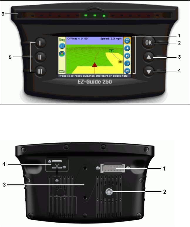
|
ITEM |
DESCRIPTION |
ITEM |
DESCRIPTION |
|
|
1 |
Action icons |
4 |
Down button |
|
|
2 |
OK button |
5 |
Function buttons |
|
|
3 |
Up button |
6 |
LEDs |
|
|
ITEM |
DESCRIPTION |
|
1 |
12−pin Deutsch power/data connector |
|
2 |
Antenna port |
4

3RAM mount fixture
4USB port
How the Buttons Work
On the front of the lightbar, there are six buttons. The buttons on the left and right sides of the lightbar work in different ways.
Action buttons (on the right of the screen)
On the main guidance screen:
|
∙ Press |
or |
to scroll through the action icons. |
|
∙ Press |
to select the highlighted icon. |
The following icons may appear to the right of the guidance screen:
|
ICON |
DESCRIPTION |
ICON |
DESCRIPTION |
|
|
Reset guidance |
Nudge left |
|||
|
Set Point A |
Nudge right |
|||
|
Set Point B |
Pause guidance |
|||
|
Start headland |
Resume guidance |
|||
|
Complete headland |
Change zoom scale |
|||
|
Pause swath recording |
Go to main Configuration menu |
|||
|
Resume swath recording |
Change view mode |
|||
|
Recording FreeForm curve (press to stop) |
Next FreeForm guidance line |
|||
|
Not recording FreeForm curve (press to start) |
Shift AB Line |
|||
|
Display point, line and area mapping icons |
Display panning icons |
|||
Note: Action icons appear only when they are appropriate. They are not all visible at all times.
The following action icons may appear on the right of a configuration screen:
|
ICON |
DESCRIPTION |
ICON |
DESCRIPTION |
|
5

|
Increase value / up to next option |
Proceed to next screen |
|||
|
Decrease value / down to next option |
Accept settings |
|||
|
In setup screens, the icons match the buttons beside them. |
Function buttons (on the left)
Beside each function button, there is an icon. When you press the function button, you select the feature that is shown on the icon.
|
ITEM |
DESCRIPTION |
|
1 |
Coverage logging icon |
|
2 |
Middle function button |
The following function icons may appear beside the buttons on the left of the screen:
|
ICON |
DESCRIPTION |
ICON |
DESCRIPTION |
|
|
Display information tab window |
Cancel changes |
|||
|
Turn on coverage logging |
Go up one menu level |
|||
|
Turn off coverage logging |
Return to guidance screen |
|||
|
Zoom in |
Move back one screen |
|||
|
Zoom out |
Display Help |
|||
6

Getting help
The EZ−Guide 250 lightbar has built−in help that explains how to use the current screen. To access the help, press the function button:
Optional Accessories
∙Ag15 antenna upgrade (P/N 92010−00)
∙All−port cable (P/N 64045)
∙Suction cup (P/N 44922)
Upgrades
The EZ−Guide 250 lightbar guidance system can be connected to the EZ−Steer® 500 assisted steering system.
Fuse Information
The EZ−Guide 250 lightbar has a 10 A glass cartridge fuse located in the cigarette lighter plug. This fuse can be replaced by the user.
Replacing the 10 A fuse
1.Locate the cigarette lighter plug holder on the end of the cable.
2.Unscrew the end cap where the spring−loaded pin protrudes. Be careful not to lose the pin after removing the end cap.
3.Remove the old fuse.
4.Insert the new fuse and then screw the end cap back onto the plug.
Serial Port Information
By default, the lightbar does not have a serial port.
However, the following optional lightbar functions require a serial connection:
7
∙Outputting simulated radar to send speed to another agricultural device, such as a yield monitor or a variable rate controller.
∙Outputting NMEA messages to an external device.
To add a serial port to the standard lightbar cable:
1.Do one of the following:
♦Order the EZ−Guide 250 all−port cable (P/N 64045).
♦Order the serial port add−on cable (P/N 63076).
2.Identify P2 on the power cable (P/N 65168). It is the black 12−pin Deutsch connector.
3.Pull out the connector wedgelock with a pair of needlenose pliers. The wedgelock is the piece of orange plastic with four square holes.
4.On the other side of the dust cover, remove the sealing pins from cavities 5, 6, and 7.
5.Insert the labeled contacts on cable P/N 63076 into the specified cavities:
♦Yellow − Cavity 5
♦Violet − Cavity 6
♦Green − Cavity 7
6.Replace the wedgelock.
8

Installation
Step 1: Installing the Antenna
Note: To minimize any interference to the GPS signal, make sure that the GPS antenna is at least 2 m (6 ft) from any other antenna (including a radio antenna). You may experience interference if you operate the vehicle within 100 m (300 ft) of any power line, radar dish, or cell phone tower.
Installing the Patch Antenna
Find the mounting location for the antenna at the front of the vehicle roof, centered from left to right.
1.On the mounting plate, remove the protective covers from the adhesive strips.
2.Attach the mounting plate to the vehicle roof with the adhesive strips. Ensure that the mounting plate is centered along the vehicle roof.
3.Place the antenna directly on the mounting plate. The magnet on the bottom of the antenna will hold it in place.
4.Route the antenna cable into the cab.
Note: For optimum performance, always use the metal antenna mount plate.
Installing the Ag15 Antenna
If you have upgraded to the Ag15 antenna, find the mounting location for the antenna at the front of the vehicle roof, centered from left to right.
1.On the mounting plate, remove the protective covers from the adhesive strips.
2.Attach the mounting plate to the vehicle roof with the adhesive strips. Ensure that the mounting plate is centered along the vehicle roof.
3.Connect the antenna cable to the antenna.
4.Place the antenna directly on the mounting plate. The three magnets embedded in the bottom of the antenna will hold it in place.
5.Route the antenna cable into the cab.
Step 2. Attaching the Lightbar Cables
The lightbar with the basic antenna and power configuration:
9

|
ITEM |
DESCRIPTION |
|
1 |
EZ−Guide 250 lightbar |
|
2 |
Patch antenna |
|
3 |
12−pin Deutsch power cable (P/N 65168) |
|
4 |
To power (cigarette lighter) |
1.Connect the power/data cable (P/N 65168) to the power port on the back of the lightbar.
2.Connect the other end of the power/data cable to the vehicle cigarette lighter.
3.Connect the antenna cable to the antenna port.
Caution: If you are using the EZ−Seer system, do not disconnect or connect any cables to the system while the lightbar is running. To connect or disconnect cables, first turn off the system with the  button.
Step 3: Turning on the Lightbar
To turn on the lightbar:
1.Plug the power cable into the cigarette lighter. If the cigarette lighter is wired through the vehicle ignition using the optional power cable, insert the key and then turn on the vehicle ignition.
2.Press the  button (the top button to the left of the screen). The lightbar turns on.
Turning off the lightbar
To turn off the lightbar, press and hold the  button.
The lightbar will begin to turn off (this takes about 5 seconds). To stop the shutdown sequence, release the button before the lightbar turns off.
10

You can leave the lightbar connected to the cable when it is turned off. It may draw a small amount of current, but it will not drain the vehicle battery.
If the lightbar loses power but then receives power again within 15 seconds, for example when cranking the vehicle starter, the lightbar will turn on automatically.
Connecting a Coverage Switch
To install the coverage switch, refer to the instructions provided with the coverage switch.
Enabling the switch on the lightbar
From the main guidance screen:
1.Press  until you have selected the
  icon.
icon.
2.Press  . The Configuration screen appears.
3.Make sure that the User Mode field is set to Advanced.
4.Select System / Guidance. The Guidance screen appears:
|
5. Select Coverage Logging and then press |
. The Coverage Logging screen appears: |
|
6. Press |
until you have selected Switch and then press |
. |
7. If necessary, set the user mode back to Easy.
Coverage logging is now set to start when you press the switch.
11

Getting Started
Quick Start Wizard
When you turn on the lightbar the Welcome to EZ−Guide screen appears automatically:
Press  . The Quick Start Wizard appears.
The wizard has several setup screens that enable you to configure important settings before you begin driving.
During the Quick Start Wizard, you can press the function button to exit at any point. The system uses any settings you have entered; for any settings that you have not yet entered, the system uses the settings from last time.
The first time that you run the lightbar, complete the whole wizard.
|
ITEM |
DESCRIPTION |
|
1 |
Quit wizard |
|
2 |
Built−in help |
|
3 |
Skip the wizard and begin driving |
12

|
To adjust a setting: |
||
|
1. Press |
or |
to select the correct value. |
|
2. Press |
to enter the selection and proceed. |
You can select whether or not the Quick Start Wizard appears next time you turn on the lightbar. If you choose to hide the wizard at startup, the lightbar skips the wizard and starts on the main guidance screen.
To alter these settings after startup, run the Quick Start Wizard from Configuration / Quick Start Wizard.
Once you complete the Quick Start Wizard, the main guidance screen appears.
Items on the Main Guidance Screen
|
ITEM |
NAME |
DESCRIPTION |
||
|
There are two status text items on the main guidance screen. The item on the left |
||||
|
1 |
Status text |
shows the distance that the vehicle is from the guidance line. The item on the right |
||
|
shows the current vehicle speed. |
||||
|
2 |
Action icons |
See How the Buttons Work |
||
|
3 |
Tips / Message |
The Tip / message panel explains the icon functions and shows driving tips. |
||
|
panel |
||||
|
4 |
USB drive |
Shows the current status of the USB drive. |
||
|
status indicator |
||||
|
5 |
Function icons |
See How the Buttons Work |
||
|
6 |
GPS quality |
Shows the quality of the GPS signal. |
||
|
icon |
||||
13

Status Indicators
On the main guidance screen, the lightbar has two status indicators.
The color of the USB drive icon shows the status of the USB drive:
ITEM DESCRIPTION
The USB drive is connected and ready
Green
Orange The USB drive is connected, but currently loading
The USB drive is disabled due to an error
Red
The color of the satellite icon shows the status of the GPS signal:
ITEM DESCRIPTION
The GPS signal is strong
Green
The GPS signal is outside acceptable settings
Orange
There is no signal
Red
View Modes
There are two views when you are driving in the field:
|
PERSPECTIVE MAP VIEW |
PLAN MAP VIEW |
|
A 3D view of the field |
A bird’s eye view of the field |
14

By default, the view switches from plan view to perspective view when you enter the field. You can change the view mode in Advanced mode.
User Modes
The EZ−Guide 250 lightbar guidance system has two user modes:
|
MODE |
DESCRIPTION |
|
Limited to accessing the most simple features. |
|
|
Easy |
Fewer action icons are available. |
|
Simplified driver options (for example, creating a guidance line is easier). |
|
|
Advanced |
The user can access all of the settings. |
Use Easy mode if you want to select a swath pattern and quickly begin driving.
Changing the User Mode
To change between Easy mode and Advanced mode:
1.Press  or
or  until you have selected the
  icon and then press
  . The Configuration screen appears.
2.Select User Mode. The User Mode screen appears:
|
3. Select Advanced or Easy and then press |
. The main guidance screen reappears, with the lightbar in |
the selected mode.
Changing the Backlight Brightness
To change the strength of the screen backlight, select Configuration / Backlight.
15
Changing the LED Brightness
To adjust the brightness of the LEDs on the lightbar, select Configuration / LED Brightness.
∙In bright sunlight, increase the brightness to make the LEDs more obvious.
∙In darker conditions, for example driving at dusk, you can lower the brightness settings so the LEDs are less intense.
Getting GPS Corrections
By default, the EZ−Guide 250 lightbar is configured to receive the following free corrections:
|
REGION |
CORRECTION |
|
North America |
WAAS |
|
Europe |
EGNOS |
These corrections provide submeter accuracy with the patch antenna, or 15 cm−20 cm (6 in−8 in) pass−to−pass accuracy when using the optional Ag15 antenna.
To change the GPS corrections (for example, to configure external GPS), select Configuration / GPS Setup / GPS
Correction Source.
For more information, see Advanced Mode: GPS Corrections.
16

Easy Mode Guidance
Introduction to Guidance
The EZ−Guide 250 lightbar uses onscreen lines, either straight or curved, to guide you. These are called the guidance lines. The most simple form of guidance line is a straight AB Line. To create an AB Line, you define a start point (the A point) and an end point (the B point). Once you define the A and B points, a straight line is drawn between them. This is your master line.
When you define the first guidance line, the lightbar copies it to create additional guidance lines.
Distance between guidance lines
When you begin to define the line, you specify the width of the implement attached to the vehicle. This width is used to calculate the distance between the guidance lines. If you do not want the guidance lines to be exactly one implement width apart, you can set an overlap or skip.
Headlands
You can record a headland boundary and get guidance to it, or you can work without a headland.
Onscreen appearance
When the main guidance screen shows the perspective view, the lines are tagged with flags that describe them.
17

ITEM DESCRIPTION
The master line that you created, and that the swaths are based on.
The A (start) and B (end) point on the master line.
The first swath to the left of the master line. (The direction «left» is relative to the direction the master line was drawn, not the vehicle’s current position).
The current swath and tag are orange.
Note: On a Pivot pattern, the swaths are numbered out from the center, not from the initial swath.
The second line to the left of the master line.
Following Guidance
The lightbar displays guidance in two places:
∙On the LEDs
∙On the screen
Guidance on the LEDs
The term LED refers to the row of 15 Light Emitting Diodes (LEDs) that are located above the screen. The LEDs that are lit up show the position of your vehicle relative to your intended guidance line. As your vehicle position changes in relation to the guidance line, the lit LED moves left or right. Use the lightbar to obtain accurate guidance, if an implement offset or implement draft is set, or for fine guidance on straight swaths.
VEHICLE POSITION LIGHTBAR APPEARANCE
Vehicle is directly on the guidance line
The three center LEDs (green) show that the vehicle is online.
Vehicle is off the guidance line
A single lit LED has moved right. This shows that the vehicle is offline to the left.
Note: This assumes that the LED Mode is set to Chase (the default). If the LED Mode is set to Pull, the LEDs move left when the vehicle is offline to the left.
18

Guidance on the screen
The lightbar screen shows the position of your vehicle in the field, the guidance line, and the offline distance, so you can tell how much you need to correct your position.
|
ITEM |
DESCRIPTION |
|
1 |
Offline distance |
|
2 |
Guidance line |
|
3 |
Vehicle position |
Guidance Patterns
The EZ−Guide 250 lightbar has seven guidance patterns so you can create guidance to suit your field layout:
Straight AB
A Straight AB is the most simple form of line. Use a straight AB Line when you do not need to define headlands and you want to drive the field in parallel straight lines.
To create a straight AB Line, define a start point (A) and an end point (B). The Straight AB Line then appears as a straight line between the two points.
19

Note: When the vehicle is on a guidance line, the line extends 1 km (0.6 miles) before Point A and 1 km beyond Point B. This makes it easier to see where the next swath is, and to get online after the turn.
Mapping an AB Line
1.Drive to the start point of the master line.
2.Set the A point:
a.Press  or
or  until you have selected the
  icon.
icon.
b.Press  . The A point is set.
3.Drive to the other end of the line.
4.Ensure that the  icon is selected and then press
  . The master AB Line appears.
5.Turn left or right for the next swath. As you move toward the next swath, it appears on the screen and turns orange to show that it is selected.
A+ line
An A+ line is also a straight line. It is defined by a single point on the line (the A point) and the heading of the line.
20

When you choose to create an A+ line, you enter the heading.
The default heading is the same as the previous AB Line. This pattern is useful for when you need guidance exactly parallel to the last AB Line, for example when:
∙driving adjacent fields
∙mapping the AB Line on a road down the side of the field
∙skipping an access road in a field
The A+ line extends 1 km (0.6 miles) before and after the A point.
Mapping an A+ Line
1.Drive to the start point of the master line.
2.Set the A point:
a.Press  or
or  until you have selected the
  icon.
icon.
b.Press  . The A point is set. Because you have already set the line heading, your master AB Line appears on the screen.
3.Follow the AB Line for guidance down the first swath.
4.Turn left or right for the next swath. As you move toward the next swath, it appears on the screen and turns orange to show that it is selected.
Identical curve
The identical curve pattern records your exact route between the A and B points, instead of a straight line.
All of the guidance lines will match the master curve, regardless of where the vehicle has driven. Use the curve pattern when you want to work the field with gentle curves.
21
 Loading…
-
Trimble EZ-Guide 250 Step 3: Selecting the line to load Press or one or more times until you select the appropriate line.1. Press . The Implement Width screen appears:2. Step 4: Setting up the implement To make optimal use of the EZ−Guide 250 system, correctly configure the implement that is attached to the vehicle. If the implement is offset and you do not configure it, there will be gaps and overlaps in your coverage. Press or to adjust the implement width and then press . The Overlap/Skip screen appears.1. Note: If you want to eliminate all skips in coverage, you can insert an overlap value to compensate for GPS errors. Do one of the follow
-
Trimble EZ-Guide 250 The Pattern Type screen appears. Step 2. Selecting a pattern Note: You automatically create a new field when you select a pattern. On the Pattern Type screen, press or until you have selected the type of pattern that you want to create. For a detailed description of each guidance pattern, see Guidance Patterns. 1. Press .2. If you selected A+, the A+ Heading screen appears. See Step 3.♦ If you selected Headland, the Headlands Circuits screen appears. See Step 3.♦ If you selected Straight AB, Identical Curve, Adaptive Curve, FreeForm, or Pivot, the main guidance screen appea
-
Trimble EZ-Guide 250 Press or until you select the desired Client name.b. Press . The Select Stored Field screen reappears.c. Select the farm, using the same process as for client.4. Select the field, using the same process as for client and farm.5. Press to select Continue .6. Press .The Choose an event screen appears.7. Step 2: Selecting or creating the event Press or until you select either New Event or Continue old event:1. Press .2. If you selected New Event, you must enter a name for the new event. Note: If you want to create a new line in this field, load an existing line, select the icon and then create a new lin
-
Trimble EZ-Guide 250 Increase value / up to next option Proceed to next screen Decrease value / down to next option Accept settings In setup screens, the icons match the buttons beside them. Function buttons (on the left) Beside each function button, there is an icon. When you press the function button, you select the feature that is shown on the icon. ITEM DESCRIPTION 1 Coverage logging icon 2 Middle function button The following function icons may appear beside the buttons on the left of the screen: ICON DESCRIPTION ICON DESCRIPTION Display information tab window Cancel c
-
Trimble EZ-Guide 250 You can delete fields that you no longer require: Select Configuration / Data Management / Manage Fields / Delete Selected Fields.1. Select the Client, Farm, and Field to delete. You can also select to delete «All».2. Select Delete Files and then press . A warning message appears.3. Press to continue. A screen with an hourglass appears.4. The files are deleted. Deleting coverage logging You can delete coverage logging to free up space in the lightbar’s internal memory: From the main guidance screen, select the icon and then press . The Configurat
-
Trimble EZ-Guide 250 Set the lightbar port parameters.1. Tip − To be able to communicate, the parameters must match those of the device. Select Next Screen and then press . The Message Selection screen appears.2. Set the various message formats to On or Off, depending on whether they are required.3. Select Next Screen and then press .4. If you turned GGA on, then select the number of decimal places in the GGA message.5. Note: Some external devices cannot read the GGA message if there are too many decimal places in the string. External Receiver Support The EZ−Guide 250 lightbar can recieve GPS positi
-
Trimble EZ-Guide 250 Deleting Features You can delete mapped features in two ways: Manually delete the closest feature in the field• Delete all the features in a selected field.• Manually deleting the closest feature To manually delete the closest feature: Enter mapping mode. Select the icon and press .1. While features are mapped in the field, the Delete Features ( ) icon is shown. Drive towards the feature you want to delete, until it is selected as the closest feature. The closest feature is indicated by a flashing white boundary. 2. Tip: Ensure that the correct feature is select
-
Trimble EZ-Guide 250 Easy Mode Guidance Introduction to Guidance The EZ−Guide 250 lightbar uses onscreen lines, either straight or curved, to guide you. These are called the guidance lines. The most simple form of guidance line is a straight AB Line. To create an AB Line, you define a start point (the A point) and an end point (the B point). Once you define the A and B points, a straight line is drawn between them. This is your master line. When you define the first guidance line, the lightbar copies it to create additional guidance lines. Distance between guidance lines When you begin to define the line, you specify the width of the implement attached to the vehi
-
About the Lightbar What’s in the EZ−Guide 250 Box The standard components of the EZ−Guide 250 system are shown below. ITEM DESCRIPTION 1 EZ−Guide 250 documentation CD 2 Quick Reference Card 3 RAM mount 4 Antenna mount plate 5 Power cable (P/N 65168) 6 EZ−Guide 250 lightbar 7 Patch antenna When you unpack the box, inspect all contents for visible damage, such as scratches or dents. If any components appear damaged, notify the shipping carrier. Keep the ship
-
To export the summary reports to the USB drive: From the main guidance screen, press one or more times until you have selected .1. Press . The Configuration screen appears.2. From the Configuration screen, select Data Management / Summary Reports. The Summary Reports screen appears. 3. Ensure that a USB drive is inserted into the EZ−Guide 250 USB slot.4. Select Send Summary Reports to USB and then press . The Send Summary to USB screen appears.5. Do one
-
Trimble EZ-Guide 250 Introduction Legal Notices (c) 2007−2009, Trimble Navigation Limited. All rights reserved. Trimble, AgGPS, EZ−Guide, and EZ−Steer are trademarks of Trimble Navigation Limited, registered in the United States and in other countries. Autopilot, Autoseed, FreeForm, OnPath, and SiteNet are trademarks of Trimble Navigation Limited. All other trademarks are the property of their respective owners. For Limited Warranty information, refer to the EZ−Guide 250 Lightbar Guidance System Release Notes. About the EZ−Guide 250 System The EZ−Guide 250 system is a GPS guidanc
-
Changing the LED Brightness To adjust the brightness of the LEDs on the lightbar, select Configuration / LED Brightness. In bright sunlight, increase the brightness to make the LEDs more obvious.• In darker conditions, for example driving at dusk, you can lower the brightness settings so the LEDs are less intense. • Getting GPS Corrections By default, the EZ−Guide 250 lightbar is configured to receive the following free corrections: REGION CORRECTION North America WAAS Europe EGNO
-
Trimble EZ-Guide 250 Version 2.00 Revision B June 2009
-
Trimble EZ-Guide 250 Connecting a device to receive speed pulses To connect the lightbar to a spray controller: Attach the R1 end of the radar cable to the P5 connector of the all−port cable (P/N 64045).1. Attach the P2 end of the radar cable to the device requiring radar speed input.2. If required, use a fly−lead to connect a spray switch to the P3 connector of the radar cable.3. Configuring the lightbar Select Configuration / System / Radar Output: . 1. Configure the radar settings:2. Radar Enabled must be On.♦ Radar Frequency Rate is the output rate expected by your device. Most Raven and M
-
Trimble EZ-Guide 250 By default, the view switches from plan view to perspective view when you enter the field. You can change the view mode in Advanced mode. User Modes The EZ−Guide 250 lightbar guidance system has two user modes: MODE DESCRIPTION Easy Limited to accessing the most simple features. Fewer action icons are available. Simplified driver options (for example, creating a guidance line is easier). Advanced The user can access all of the settings. Use Easy mode if you want to select a swath pattern and quickly begin driving. Changing the User Mode To change between Easy mode and Advanced mode: Press or until
-
On the Headlands Circuits screen, press or until the screen displays the required number of circuits. 1. Press . The main guidance screen appears.2. Step 4. Defining the pattern on the field Drive to the start point.1. Note: For a headland, set the start point and begin to drive. Set the A point.2. Drive the guidance line.3. Note: To accurately define a pivot, put the vehicle wheel in a center pivot near the outside edge of the field. Map the B point (if necessary).4. Note: For a headland,
-
Trimble EZ-Guide 250 Advanced Mode Additional Information Views There are two possible views when you are driving in the field in Advanced mode: PERSPECTIVE MAP VIEW PLAN MAP VIEW The view that is shown is controlled by the view mode: ITEM DESCRIPTION Auto Headlands (default) Shows the perspective map view on swaths and the plan map view in headlands. Auto Engage Shows the perspective map view when the EZ−Steer system is engaged and the plan map view when the system is disengaged. Manual You can manually change between the perspective map view and the plan map view using the
-
Trimble EZ-Guide 250 If you want a space between your passes, press to enter a skip distance.♦ Press . The Forward/Back Offset screen appears.3. Enter the distance that the implement is offset back from the antenna and then press . The Left/Right Offset screen appears. 4. Enter the distance that the implement is offset to the left or right of the antenna and then press . The Pattern Type screen appears. 5. Step 3: Select the pattern type Select which of the seven guidance patterns you want to base guidance on. For a description of the different field patterns, see Guidance Patterns. Some guidance patterns require additiona
-
Table of Contents Advanced Mode Additional Information………………………………………………………………………………………………..46 Views………………………………………………………………………………………………………………………………………..46 Panning………………………………………………………………………………………………………………………………………46 Night Mode……………………………………………………………………..
-
Trimble EZ-Guide 250 Drive to the start point of the headland.1. Select the icon and then press to set the start point of the headland.2. Begin to drive the circuit of the headland.3. Note: To ensure straight sides on the headland, you can use the pause feature. See Straight sections on curves. While you are driving the circuit, set the A point of your guidance line.4. When you have defined the internal pattern guidance line, the start−point circle appears around the start point of the headland. Note: If you return to the start of the headland before
-
To change when coverage logging is enabled: In Advanced mode, select Configuration / System / Guidance / Coverage Logging. The Coverage Logging screen appears. 1. Select the appropriate setting and then press .2. Adding a Time Delay to Coverage Logging There may be a delay between the time when you start or stop drawing coverage onscreen and the time when the implement actually starts or stops coverage. For example, some spray valves can take 1.5 seconds to open or close. To compensate for this, you can add a time delay to the drawi
-
Trimble EZ-Guide 250 The nudge value is displayed on the Tip/Message bar at the bottom of the screen while a nudge icon is highlighted • The first information tab shows the current nudge value. Press the function button.• Resetting nudge after each row You can configure the lightbar to reset the nudged position each time you change rows: Select Configuration / System / Guidance / Clear Nudge at Swath End.1. Select On and then press .2. Each time you move from one swath to the next, the nudge value will reset to 0, and the swaths will return to their original position. The shift icon Shift moves the guidance line directly to the vehicle position. Shift enabl
-
Trimble EZ-Guide 250 To upgrade the lightbar firmware: Download the self−extracting firmware file from www.EZ−Guide.com to your office computer.1. Run the file and extract the contents to a temporary directory.2. Copy the files from the temporary directory to the USB drive.3. Insert the USB drive in the lightbar.4. Turn on the lightbar. When the USB drive is detected, the lightbar runs the upgrade wizard.5. Select the EZ−Guide firmware .img file and then press . The wizard installs the new firmware.6. Caution: Do
-
Installation Step 1: Installing the Antenna Note: To minimize any interference to the GPS signal, make sure that the GPS antenna is at least 2 m (6 ft) from any other antenna (including a radio antenna). You may experience interference if you operate the vehicle within 100 m (300 ft) of any power line, radar dish, or cell phone tower. Installing the Patch Antenna Find the mounting location for the antenna at the front of the vehicle roof, centered from left to right. On the mounting pla
-
Trimble EZ-Guide 250 3 RAM mount fixture 4 USB port How the Buttons Work On the front of the lightbar, there are six buttons. The buttons on the left and right sides of the lightbar work in different ways. Action buttons (on the right of the screen) On the main guidance screen: Press or to scroll through the action icons.• Press to select the highlighted icon.• The following icons may appear to the right of the guidance screen: ICON DESCRIPTION ICON DESCRIPTION Reset guidance Nudge left Set Point A Nudge right Set Point B Pause guidance Start headland Resume guidance Complete headland Change zoom scale Pause swath recording Go t
-
Note: Always set the master line near the outer edge of the field. Drive to the start point of the pivot.1. Position one wheel of the vehicle in a pivot wheel rut, with the rear of the vehicle to the pivot arm. If the field is not a full circle pivot, face the rear of the vehicle to the edge of the field. 2. Set the A point:3. Press or until you have selected the icon.a. Press . The A point is set.b. Drive around the field. Keep the vehicle wheel in the rut. The lightbar does not yet provide guidance.4. When you have driven at least 1/4 of the pivot cir
-
Table of Contents Introduction……………………………………………………………………………………………………………………………………………1 Legal Notices……………………………………………………………………………………………………………………………….1 About the EZ−Guide 250 System……………………………………………………………………..
-
Trimble EZ-Guide 250 In the File system list, select FAT and then click Start.4. The USB drive is formatted with the FAT file system. Inserting a USB drive You can connect a USB drive to the USB port on the back of the lightbar: Ensure that the lightbar is turned off.1. Insert the USB drive into the USB port.2. Turn on the lightbar.3. Note: To reduce any delay caused by the lightbar scanning the USB drive, keep the number of fields on the USB drive to a minimum. Removing a USB drive Caution − If you remove a USB drive from the lightbar while the lightbar is turned on, you risk corrupting the data. To avoid this, do the following: Tur
-
Press to select Delete Features.2. Press . The Delete Features screen appears.3. Select the Client, Farm and Field containing features you want to delete.4. Select Delete Files and press . A confirmation screen appears.5. Press .6. The mapped feature files for the select field are deleted. 77
-
Trimble EZ-Guide 250 Select Configuration / System / GPS / GPS Setup.2. Change the GPS Correction Source option to Ext. TSIP.3. Select Continue and press . The Connecting to External Receiver screen appears. The lightbar connects to the TSIP receiver. The message Connection Established appears. 4. Press . The External DGPS Source screen appears, showing the available corrections on the reciever.5. Select the appropriate correction source and then press . The wizard for that correction type appears.6. Note: When the lightbar is receiving GPS positions from the TSIP−compatible receiver, additional entries appear on the Info tab. Using Omni
-
Follow these steps in the wizard: Configure the implement.1. Select the pattern type.2. Drive and define the guidance line.3. Step 1: Configure the implement The Implement Width screen appears: Press or to adjust the implement width and then press . The Overlap/Skip screen appears.1. Do one of the following:2. If you want your passes to meet so you have full coverage without overlaps, use the default Overlap/Skip value. ♦ If you want your passes to overlap, press to enter an overlap distance.♦ If you want
-
Selecting the Field name from a list You can select the field from a list of names, instead of a map. This can be useful if the lightbar is not receiving a GPS signal. To select a field from a list of names: From the Create new field or select old field screen, select Select Stored Field .1. Press . The Select Stored Field screen appears.2. Select the client.3. Press to select Client and press . The Client screen appears.a. 43
-
Nudge Nudge a guidance line if you need to correct for: GPS position drift when returning to the field for guidance, for example, after pausing or turning the unit off and on • GPS satellite constellation changes while driving in the field• Each nudge moves the guidance line by the Nudge Increment value. For example, if the Nudge Increment value is set to 3″ and you press twice, the total nudge distance is 6″ to the right. The nudge left and nudge ri
-
Trimble EZ-Guide 250 ITEM DESCRIPTION The master line that you created, and that the swaths are based on. The A (start) and B (end) point on the master line. The first swath to the left of the master line. (The direction «left» is relative to the direction the master line was drawn, not the vehicle’s current position). The current swath and tag are orange. Note: On a Pivot pattern, the swaths are numbered out from the center, not from the initial swath. The second line to the left of the master line. Following Guidance The lightbar displays guidance in two places: On the LEDs• On the s
-
To enter panning mode, select the icon and press . A new set of panning icons appears on the right of the screen. Note: The map is always displayed North−Up in panning mode. To move the screen, select one of the arrow icons on the right of the screen and press . The screen moves in the direction of the arrow. Repeat with the same arrow or change arrows as many times as necessary. To zoom in or out on the screen, use the buttons on the left of the screen
-
Trimble EZ-Guide 250 If the lightbar is not already in Advanced mode, change it to Advanced mode by selecting Configuration / User Mode. 1. Select Configuration / Mapping and then press . The Mapping menu appears.2. Press to select Point , Line or Area and press to display the Point, Line or Area feature configuration screen. 3. Press . The Warning Distance screen appears.4. Press or to change the warning distance.5. Press .6. Note: Set the warning distance large enough to be safe for the entire vehicle length. You should consider the implement length as well as the tractor length. Dis
-
Advanced Mode GPS Corrections Configuring the GPS Corrections The term GPS corrections refers to the type of GPS signal that you receive. ITEM DESCRIPTION WAAS (Wide Area Augmentation System) WAAS corrections are an overlay to the normal GPS signal to improve accuracy. WAAS is available only in the United States of America, southern Canada, and the northern parts of Mexico. It is free to use. When using WAAS corrections, the EZ−Guide 250 system downloads th
-
Trimble EZ-Guide 250 Advanced Mode Data Management USB Drive Compatibility The EZ−Guide 250 lightbar saves data to and from a USB drive using a FAT file system. Caution − Multi−function devices, for example iPods or MP3 players, are not compatible with the lightbar. Do not reformat these devices to use the FAT file system, as this may delete their firmware and prevent them from operating correctly. The following drive is compatible with the lightbar: Lexar Firefly 1 GB (P/N 64268−1G). For more information, contact your local reseller.• The following d
-
Trimble EZ-Guide 250 ITEM DESCRIPTION ITEM DESCRIPTION 1 Action icons 4 Down button 2 OK button 5 Function buttons 3 Up button 6 LEDs ITEM DESCRIPTION 1 12−pin Deutsch power/data connector 2 Antenna port 4
-
Trimble EZ-Guide 250 Note: There can be a delay between the time when you start or stop applying coverage onscreen, and the time when the implement actually starts or stops coverage. To compensate for this, you can add a time delay to the drawing of coverage logging so the lightbar more accurately shows what is actually occurring. This requires the lightbar to be in Advanced mode. See Coverage Logging Delay. Creating straight sections on Headland or Curve swaths You can create straight sections when recording headland or curve swaths: Select the acti
-
Trimble EZ-Guide 250 Getting Started Quick Start Wizard When you turn on the lightbar the Welcome to EZ−Guide screen appears automatically: Press . The Quick Start Wizard appears. The wizard has several setup screens that enable you to configure important settings before you begin driving. During the Quick Start Wizard, you can press the function button to exit at any point. The system uses any settings you have entered; for any settings that you have not yet entered, the system uses the settings from last time. The first time that you run the lightbar, complete the whole wizard. ITEM DESCRIPTION 1 Quit wizard 2 Built−in help 3
-
Adjust the value and then press .2. ITEM DESCRIPTION Minimum Elevation Elevation refers to the angle at which a satellite appears in the sky (higher is better). The Minimum Elevation setting is the minimum angle in the sky at which the lightbar will acknowledge satellites. If you are having trouble receiving corrections, lower this setting. Minimum SNR SNR (Signal to Noise Ratio) is a measure of the quality of a GPS signal. It is the ratio of useful information received to noise. A high SNR value is better. If you are having trouble receiving corrections, raise
-
Trimble EZ-Guide 250 When the lightbar receives OmniSTAR corrections from a TSIP−compatible receiver, the convergence time is reported differently. Using RTK corrected positions over TSIP When you use RTK positions from an external receiver, you can configure the network ID using the Network ID setting. On the main map screen, the Info tab shows a diagnostic called Link Quality . This describes the quality of the radio signal, and as a result the RTK signal. Depending on the quality of the signal coming in, the Link Quality item will show one of the following indicators: Excellent• Good• Fair• Poor• 61
-
Trimble EZ-Guide 250 Outputting simulated radar to send speed to another agricultural device, such as a yield monitor or a variable rate controller. • Outputting NMEA messages to an external device.• To add a serial port to the standard lightbar cable: Do one of the following:1. Order the EZ−Guide 250 all−port cable (P/N 64045).♦ Order the serial port add−on cable (P/N 63076).♦ Identify P2 on the power cable (P/N 65168). It is the black 12−pin Deutsch connector.2. Pull out the connector wedgelock with a pair of needlenose pliers. The wedgelock is the piece of orange plastic with four square holes. 3. On th
-
Trimble EZ-Guide 250 Connect the USB drive. See USB Compatibility1. Select Configuration / Data Management / Manage Fields / Get Fields from USB.2. Do one of the following:3. Select the specific client, farm, and field to import.♦ Select All to get all of the data in a category to the USB drive.♦ Note: If you select All, you do not need to select the later options. Select Import Files and then press . A warning message appears.4. Press to continue. A screen with an hourglass appears.5. The files are imported from the USB drive.
-
Trimble EZ-Guide 250 When you choose to create an A+ line, you enter the heading. The default heading is the same as the previous AB Line. This pattern is useful for when you need guidance exactly parallel to the last AB Line, for example when: driving adjacent fields• mapping the AB Line on a road down the side of the field• skipping an access road in a field• The A+ line extends 1 km (0.6 miles) before and after the A point. Mapping an A+ Line Drive to the start point of the master line.1. Set the A point:2. Press or until you have selected the icon.a. Press . The A point is set. Because you have already set the line heading
-
Trimble EZ-Guide 250 Mapping an Identical Curve Drive to the start point of the curve.1. Set the A point:2. Press or until you have selected the icon.a. Press . The A point is set.b. Drive the initial curve.3. Ensure that the icon is selected and then press . The master line appears on the screen.4. Turn left or right for the next swath. As you move toward the next swath, it appears on the screen and turns orange to show that it is selected. 5. Adaptive curve The adaptive curve pattern is similar to the identical curve pattern. It provides guidance along a curve. However, the adaptive curve pattern updates guidance af
-
Obtaining Information from the Lightbar The About the EZ−Guide Screen You can view the About the EZ−Guide screen in Easy or Advanced mode. To view the About the EZ−Guide screen, select Configuration / About the EZ−Guide. If you need to ask for support, have this information available. Information Tabs The lightbar has several information tabs that you can display over the screen. They can be viewed in Easy or Advanced mode. The tabs are see−through, so you can still see the vehicle underneath. To view an informatio
-
Continue to drive the swaths, setting the B point at the end of each one.5. Using the adaptive curve pattern for rowfinding In Advanced mode, select Configuration / System / Guidance and then set the Auto U−Turn detection option to Off. 1. Reset guidance:2. Enter the width of the implement.a. Create a guidance line based on the adaptive curve pattern.b. Set the B point at the end of each row.3. Turn the vehicle toward the next swath. When the vehicle is halfway through the turn,
-
A message appears to warn that you will load the configuration over the current configuration. Press to proceed, or press the function button to exit without loading. Summary Report The lightbar can produce multi−page field summaries that contain a field map and report. These summaries are in RTF format and can be viewed on an office computer. The summary report is automatically created when you close the field. (A field is closed when you run the New Field Wizard). The summary report has the same name as the field. Note: To view the graphics in the files, you may need to install t
-
Trimble EZ-Guide 250 Note: By default, the line feature is mapped at the antenna location. To change where a feature is mapped, see Recording Position . Mapping area features To map an area feature: From mapping mode, select and press . The area feature mapping icons appear.1. Press to select the appropriate area feature icon:2. ITEM DESCRIPTION Map a generic area feature. Map an exclusion zone. Press . The lightbar begins recording the area feature.3. Drive around the area feature.4. To complete the area feature, check that
-
Select one of the following:3. ITEM DESCRIPTION Cancel Exit without moving the guidance line Shift but Don’t Save The line moves to your current location, but when you exit the field the previous line position is retained Shift and Save New The line moves to your current position and is permanently saved in the new location Configuring the Lightbar Setting the LED brightness You can adjust the brightness of the LEDs on the lightbar. In bright sunlight, increase the brightness to make the LEDs more obvious. In darker conditions,
-
Trimble EZ-Guide 250 Event The event or application that is being applied on a particular «field» (see above). For example: − Spraying − Harvesting A client may have several farms, each of the farms may consist of several fields, and each field may be broken into a number of events. Default Field Names By default, the client, farm, field, and event names are automatically generated. The default names are: ITEM DESCRIPTION Client Default_Client Farm Default_Farm Field Date _ Increment _EZ SerialNumber Event Event_ Date _ Increment _EZ SerialNumber Note: Date is in the format YYMMDD and Increment i
-
Trimble EZ-Guide 250 Note: When the vehicle is on a guidance line, the line extends 1 km (0.6 miles) before Point A and 1 km beyond Point B. This makes it easier to see where the next swath is, and to get online after the turn. Mapping an AB Line Drive to the start point of the master line.1. Set the A point:2. Press or until you have selected the icon.a. Press . The A point is set.b. Drive to the other end of the line.3. Ensure that the icon is selected and then press . The master AB Line appears.4. Turn left or right f
-
Trimble EZ-Guide 250 For information on how to calibrate the unit, refer to the controller instruction manual. Note: To check the accuracy of your current settings, compare the speed value indicated on the lightbar guidance system with that on the spray controller. Recording Events The EZ−Guide 250 lightbar can record events for playback. Only use this feature if directed to by your support provider. Restoring the Default Lightbar Settings Note: When you reset the lightbar default settings, your field information remains unchanged. Select Configuration / System / Restore Defaults. The Restore Defa
-
Trimble EZ-Guide 250 Advanced Mode Guidance Resetting Guidance Use the icon to create or load a field or line. To reset guidance: Select the icon and press . The Finished With Field? screen appears:1. Select one of the two options and then press :2. Yes − To map a new field (see Creating a New Field or Line ) or select an existing field (see Selecting a Field ). ♦ No − To map a new AB Line (see Creating a New Line ) or select an existing AB Line in the current field (see Selecting an AB Line ). ♦ Note: If you selec
-
Trimble EZ-Guide 250 Depending on the pattern type that you selected, one of the following icons is now available: (start AB Line, A+, Identical Curve, Adaptive Curve, Pivot, or FreeForm straight section)• (start Headland)• (not currently recording FreeForm curve − select to begin recording)• Drive to the start point and then select this icon to begin defining guidance. For more information about the various field patterns, see Guidance Patterns. Selecting (Loading) an AB Line When you create multiple lines in a field, you need to select the appropriate line. You do not have to actively save an AB Line for it to be stored. AB Lines are stored aut
-
Trimble EZ-Guide 250 Note: No matter how many circuits you are creating, you only define the outside headland. The inner headlands circuits are copied from that original circuit. Internal pattern The internal pattern is the pattern of the guidance lines inside the headland. In Easy mode, the internal pattern is automatically an AB Line. In Advanced mode, there is a choice of two internal pattern types: ITEM DESCRIPTION Straight AB Creates standard parallel swaths inside a headland A+ Creates parallel swaths at a pre−defined heading Ending the headland Note: You ne
-
Drive and define the guidance line.4. Step 1: Enter the field and event names The Confirm Configuration screen appears. Select the Client option and then press .1. Do one of the following:2. Select an existing client from the list.♦ Enter a new client name.♦ Accept the default name.♦ Repeat Step 2 for the Farm, Field, and Event options.3. Select Continue and then press .4. Step 2: Configure the implement The Implement Width screen appears: Press or to adjust the implement width and t
-
Trimble EZ-Guide 250 ITEM DESCRIPTION 1 EZ−Guide 250 lightbar 2 Patch antenna 3 12−pin Deutsch power cable (P/N 65168) 4 To power (cigarette lighter) Connect the power/data cable (P/N 65168) to the power port on the back of the lightbar.1. Connect the other end of the power/data cable to the vehicle cigarette lighter.2. Connect the antenna cable to the antenna port.3. Caution: If you are using the EZ−Seer system, do not disconnect or connect any cables to the system while the lightbar is running. To connect or disconnect cables, first
-
Status Screens The Status screens can be viewed in Advanced mode. To display the Status menu, select Configuration / Status. You can access seven screens from the Status menu: SCREEN DESCRIPTION GPS Status Displays information about your position and the current GPS signal strength. Satellite Status Displays information about the current GPS satellites. DGPS Status Displays which DGPS signal is selected. It is set at System / GPS / GPS Setup. System Status Di
-
Trimble EZ-Guide 250 Table of Contents Obtaining Information from the Lightbar Warning Messages………………………………………………………………………………………………………………………79 Troubleshooting………………………………………………………………………………………………………………………….79 iii
-
Trimble EZ-Guide 250 Do one of the following for each of the Client, Farm, and Field options:3. Select the specific item to export.♦ Select All to export all of the entries.♦ Select Export Files and then press . A warning screen appears.4. Press to continue. A screen with an hourglass appears:5. The data is exported. Exporting large fields Tip: To export a large field, create a temporary new A+ field with no logging in it and then export the large field. This will ensure that the large field is correctly closed before it is exported. Clearing Storage Sp
-
Trimble EZ-Guide 250 Selected the appropriate line and then press . The Create New Field screen appears.b. If necessary, change the implement settings.c. Step 2: Setting up the implement (if necessary) To make optimal use of the EZ−Guide 250 system, correctly configure the implement that is attached to the vehicle. If the implement is offset and you do not configure it, there will be gaps and overlaps in your coverage. Press or to adjust the implement width and then press . The Overlap/Skip screen appears.1. Note: If you want to eliminate all skips in coverage, you can insert an overlap value to compensate for GPS e
-
Trimble EZ-Guide 250 A positive timezone indicates a zone that is ahead of Greenwich, England. A negative timezone is behind. Driving on Large Fields At distances greater than 10 km (6.2 miles) from the original AB Line, the curvature of the Earth’s surface can cause a reduction in GPS position accuracy. Consequently, the lightbar does not support more than 1024 swaths to the left and 1024 swaths to the right of the original AB Line. If you need to create more than 1024 swaths either to the left or the right of the AB Line, do one of the followi
-
Status Indicators On the main guidance screen, the lightbar has two status indicators. The color of the USB drive icon shows the status of the USB drive: ITEM DESCRIPTION Green The USB drive is connected and ready Orange The USB drive is connected, but currently loading Red The USB drive is disabled due to an error The color of the satellite icon shows the status of the GPS signal: ITEM DESCRIPTION Green The GPS signal is strong Orange The GPS signal is outside acceptable settings Red There is no signal View Modes There are two views when you are dr
-
Select the field to load.1. Select or create the event.2. Select the line to load.3. Set up the implement (if necessary).4. These steps are described below. Step 1. Selecting the field to load There are two ways you can select a field to load: Using FieldFinder• Selecting the Field name from a list• Using FieldFinder The FieldFinder option allows you to choose a field from a map view. Note: The vehicle must be within 200 m of the field for it to appear on screen. To use FieldFinder: From the Cr
-
Trimble EZ-Guide 250 guidance lines. To use the Next AB icon, the vehicle must be within 1.5 swath widths of a FreeForm curve. The following example shows how the Next AB icon works: ITEM EXAMPLE There are three guidance lines available. The system is currently showing guidance on the closest FreeForm curve, but you want guidance on the line that curves to the right. To snap guidance to the next nearest FreeForm curve, press the Next AB icon. Guidance snaps to the line that curves to the right. To snap guidance to the straight line at the top of the screen, press the next AB icon again. Using FreeForm curves in spiral fields (round and r
-
Trimble EZ-Guide 250 Press to select the appropriate point feature icon.2. ICON DESCRIPTION Map a rock point feature Map a weed point feature Map a tree point feature Map another generic point feature Press . The point feature is mapped.3. Note: By default, the point feature is mapped at the antenna location. To change where a feature is mapped, see Recording Position . Mapping line features To map a line feature: From mapping mode, select and press . The line feature mapping icon appears.1. Press to select .2. Press . The lightbar begins recording the line feature.3. Drive the length of the line feature.4.
-
The current guidance line that you were on is displayed, even if you drive onto another swath.• The pause function remembers your position even if the lightbar is turned off.• A straight, dotted line is drawn from the pause position to the position of the vehicle.• Returning to the pause position Turn the vehicle until the Heading status text item is 0.0° (so you are heading directly toward the pause position). 1. Drive forward until the Distance status text item is close to 0.00 m (0′ 0″). This
-
Press to select Point, Line or Area and press to display the configuration screen for the feature type. 3. Press to select Recording Position and press . The Recording Position screen appears.4. Select the appropriate recording position and press .5. Warning Zones When a point, line, or area feature is mapped, you can configure a warning zone around the feature. When the vehicle enters the warning zone around a feature, the lightbar provides a visual and audible wa
-
Trimble EZ-Guide 250 Mapping Introduction to Mapping The EZ−Guide 250 can map point, line and area features. Note: Mapping is disabled if you do not have good quality GPS. To enter mapping mode, select the icon and press . While in mapping mode you can map point, line and area features. In mapping mode, the following feature mapping icons appear on the right of the screen: ITEM DESCRIPTION Display point feature mapping icons Display line feature mapping icons Display area feature mapping icons Mapped features are saved with the field.
-
Trimble EZ-Guide 250 To adjust a setting: Press or to select the correct value.1. Press to enter the selection and proceed.2. You can select whether or not the Quick Start Wizard appears next time you turn on the lightbar. If you choose to hide the wizard at startup, the lightbar skips the wizard and starts on the main guidance screen. To alter these settings after startup, run the Quick Start Wizard from Configuration / Quick Start Wizard. Once you complete the Quick Start Wizard, the main guidance screen appears. Items on the Main Guidance Screen ITEM NAME DESCRIPTION 1 Status text The
-
Note: When the FreeForm Recording mode is set to coverage, you can use either the icon or the icon method for recording. Note: If the Auto U−Turn Detection option is set to Off, you must manually stop recording at the end of each pass and then start recording again at the beginning of the next pass. Defining a straight AB Line with the FreeForm pattern Select the icon to set the A point.1. Drive to the other end of the line.2. Select the icon to end the line.3. Getting guidance on curved segments After you have defined a guidance line, there are two ways to get guidan
-
Select the appropriate correction method and then press . The GPS Source screen reappears. The correction appears as the Source. 2. Press to select Next Screen and then press .3. Configuring WAAS/EGNOS To configure WAAS or EGNOS corrections, set each of the fields on the WAAS/EGNOS Settings screen: ITEM DESCRIPTION Correction Limit The time that the lightbar can run without receiving an updated GPS position, before it drops guidance. Satellite The correction satellite that the lightbar will use. To automatically select the satellite, select Auto Select. Otherwise, you can select a spe
-
Using FreeForm curves in fields with variable terrain Start and stop recording guidance at the ends of each pass. If there are 2 guidance lines in close proximity, use the Next AB icon to snap to the correct line. At any point, you can add a straight AB Line for repeated straight line guidance. Use the icon to switch between straight AB and FreeForm curve guidance lines. Getting Guidance The icon enables you to create a guidance line and begin driving in the field. D
-
Trimble EZ-Guide 250 MODE DESCRIPTION Chase (default) Chase the LEDs to stay online. The LEDs represent the swath location relative to the vehicle. For example, if the vehicle moves offline to the left, the lit LEDs move right. Pull Center the LEDs to stay online. The LEDs represent the vehicle position relative to the swath. For example, if the vehicle moves offline to the left, the lit LEDs also move left. To change the LED mode, select Configuration / System / Guidance / LED Mode. LED spacing The LED spacing is the distance that
-
Trimble EZ-Guide 250 Getting help The EZ−Guide 250 lightbar has built−in help that explains how to use the current screen. To access the help, press the function button: Optional Accessories Ag15 antenna upgrade (P/N 92010−00)• All−port cable (P/N 64045)• Suction cup (P/N 44922)• Upgrades The EZ−Guide 250 lightbar guidance system can be connected to the EZ−Steer® 500 assisted steering system. Fuse Information The EZ−Guide 250 lightbar has a 10 A glass cartridge fuse located in the cigarette lighter plug. This fuse can be replaced by the user. Replacing the 10 A fuse Locate t
-
Trimble EZ-Guide 250 Set the A and B points• Set the A point and perform a U−turn onto the next swath (which is automatically detected)• The method that you use depends on the Auto U−Turn detection setting. Changing the Auto U−Turn detection setting Note: To change the Auto U−turn detection, the lightbar must be in Advanced mode. Select Configuration / System / Guidance. The Guidance screen appears.1. Adjust the Auto U−Turn detection setting.2. Mapping an Adaptive Curve There are two ways to use the adaptive curve pattern: Automatically: Set the Auto U−turn detectio
-
You can leave the lightbar connected to the cable when it is turned off. It may draw a small amount of current, but it will not drain the vehicle battery. If the lightbar loses power but then receives power again within 15 seconds, for example when cranking the vehicle starter, the lightbar will turn on automatically. Connecting a Coverage Switch To install the coverage switch, refer to the instructions provided with the coverage switch. Enabling the switch on the lightbar From the main guidance screen: Press until you have selected the icon.1. Press . The Configuratio
-
The FreeForm Recording option When you are driving a curve, you need to record your path so the lightbar can create your next guidance line. There are several different options that control when the lightbar records your path: ITEM DESCRIPTION Manual The icon enables you to manually start recording a FreeForm curve and the icon enables you to manually end recording. Coverage A FreeForm curve is recorded whenever coverage logging is enabled. To adjust the FreeForm Recording option:
-
The FreeForm Recording option When you are driving a curve, you need to record your path so the lightbar can create your next guidance line. There are several different options that control when the lightbar records your path: ITEM DESCRIPTION Manual The icon enables you to manually start recording a FreeForm curve and the icon enables you to manually end recording. Coverage A FreeForm curve is recorded whenever coverage logging is enabled. To adjust the FreeForm Recording option: Set the lightbar to Advanced mode.1. Select Configuration / System / Guidance / Fr
-
Trimble EZ-Guide 250 Note: There can be a delay between the time when you start or stop applying coverage onscreen, and the time when the implement actually starts or stops coverage. To compensate for this, you can add a time delay to the drawing of coverage logging so the lightbar more accurately shows what is actually occurring. This requires the lightbar to be in Advanced mode. See Coverage Logging Delay. Creating straight sections on Headland or Curve swaths You can create straight sections when recording headland or curve swaths: Select the act
-
Trimble EZ-Guide 250 Installation Step 1: Installing the Antenna Note: To minimize any interference to the GPS signal, make sure that the GPS antenna is at least 2 m (6 ft) from any other antenna (including a radio antenna). You may experience interference if you operate the vehicle within 100 m (300 ft) of any power line, radar dish, or cell phone tower. Installing the Patch Antenna Find the mounting location for the antenna at the front of the vehicle roof, centered from left to right. On the mounting plate, remove the protective covers from the adhesive strips.1. Attach the mounting plate to the vehicle roof with
-
Trimble EZ-Guide 250 Table of Contents Introduction……………………………………………………………………………………………………………………………………………1 Legal Notices……………………………………………………………………………………………………………………………….1 About the EZ−Guide 250 System……………………………………………………………………………………………………1 Related Information………….
-
Trimble EZ-Guide 250 Note: No matter how many circuits you are creating, you only define the outside headland. The inner headlands circuits are copied from that original circuit. Internal pattern The internal pattern is the pattern of the guidance lines inside the headland. In Easy mode, the internal pattern is automatically an AB Line. In Advanced mode, there is a choice of two internal pattern types: ITEM DESCRIPTION Straight AB Creates standard parallel swaths inside a headland A+ Creates parallel swaths at a pre−defined heading Ending the headland Note: You need to define the master
-
If you want a space between your passes, press to enter a skip distance.♦ Press . The Forward/Back Offset screen appears.3. Enter the distance that the implement is offset back from the antenna and then press . The Left/Right Offset screen appears. 4. Enter the distance that the implement is offset to the left or right of the antenna and then press . The Pattern Type screen appears. 5. Step 3: Select the pattern type Select which of the seven guidance patterns you want to base guidance on. For a description of the different field patterns, see Guidance Patterns.
-
Table of Contents Obtaining Information from the Lightbar Warning Messages………………………………………………………………………………………………………………………79 Troubleshooting………………………………………………………………………………………………………………………….79 iii
-
Trimble EZ-Guide 250 Guidance on the screen The lightbar screen shows the position of your vehicle in the field, the guidance line, and the offline distance, so you can tell how much you need to correct your position. ITEM DESCRIPTION 1 Offline distance 2 Guidance line 3 Vehicle position Guidance Patterns The EZ−Guide 250 lightbar has seven guidance patterns so you can create guidance to suit your field layout: Straight AB A Straight AB is the most simple form of line. Use a straight AB Line when you do not need to define headlands and you want to drive the field in parallel straight lines. To create a str
-
Advanced Mode GPS Corrections Configuring the GPS Corrections The term GPS corrections refers to the type of GPS signal that you receive. ITEM DESCRIPTION WAAS (Wide Area Augmentation System) WAAS corrections are an overlay to the normal GPS signal to improve accuracy. WAAS is available only in the United States of America, southern Canada, and the northern parts of Mexico. It is free to use. When using WAAS corrections, the EZ−Guide 250 system downloads the WAAS ionosphere model within the first 10 minutes of operation, which improves acc
-
Trimble EZ-Guide 250 ITEM DESCRIPTION 1 EZ−Guide 250 lightbar 2 Patch antenna 3 12−pin Deutsch power cable (P/N 65168) 4 To power (cigarette lighter) Connect the power/data cable (P/N 65168) to the power port on the back of the lightbar.1. Connect the other end of the power/data cable to the vehicle cigarette lighter.2. Connect the antenna cable to the antenna port.3. Caution: If you are using the EZ−Seer system, do not disconnect or connect any cables to the system while the lightbar is running. To connect or disconnect cables, first turn off the system with the button. Step 3: Turning
-
Trimble EZ-Guide 250 Note: When the vehicle is on a guidance line, the line extends 1 km (0.6 miles) before Point A and 1 km beyond Point B. This makes it easier to see where the next swath is, and to get online after the turn. Mapping an AB Line Drive to the start point of the master line.1. Set the A point:2. Press or until you have selected the icon.a. Press . The A point is set.b. Drive to the other end of the line.3. Ensure that the icon is selected and then press . The master AB Line appears.4. Turn left or right fo
-
Trimble EZ-Guide 250 Getting help The EZ−Guide 250 lightbar has built−in help that explains how to use the current screen. To access the help, press the function button: Optional Accessories Ag15 antenna upgrade (P/N 92010−00)• All−port cable (P/N 64045)• Suction cup (P/N 44922)• Upgrades The EZ−Guide 250 lightbar guidance system can be connected to the EZ−Steer® 500 assisted steering system. Fuse Information The EZ−Guide 250 lightbar has a 10 A glass cartridge fuse located in the cigarette lighter plug. This fuse can be
-
Using FreeForm curves in fields with variable terrain Start and stop recording guidance at the ends of each pass. If there are 2 guidance lines in close proximity, use the Next AB icon to snap to the correct line. At any point, you can add a straight AB Line for repeated straight line guidance. Use the icon to switch between straight AB and FreeForm curve guidance lines. Getting Guidance The icon enables you to create a guidance line and begin driving in the field. Depending on which pattern you select, follow these steps: Enter the vehicle information.1. Select a pattern.2. Ent
-
Trimble EZ-Guide 250 Select the appropriate correction method and then press . The GPS Source screen reappears. The correction appears as the Source. 2. Press to select Next Screen and then press .3. Configuring WAAS/EGNOS To configure WAAS or EGNOS corrections, set each of the fields on the WAAS/EGNOS Settings screen: ITEM DESCRIPTION Correction Limit The time that the lightbar can run without receiving an updated GPS position, before it drops guidance. Satellite The correction satellite that the lightbar will use. To automatically select the satellite, select Auto Select
-
Trimble EZ-Guide 250 About the Lightbar What’s in the EZ−Guide 250 Box The standard components of the EZ−Guide 250 system are shown below. ITEM DESCRIPTION 1 EZ−Guide 250 documentation CD 2 Quick Reference Card 3 RAM mount 4 Antenna mount plate 5 Power cable (P/N 65168) 6 EZ−Guide 250 lightbar 7 Patch antenna When you unpack the box, inspect all contents for visible damage, such as scratches or dents. If any components appear damaged, notify the shipping carrier. Keep the shipping and packaging material for the carrier’s inspection. Parts of the Lightbar The f
-
To upgrade the lightbar firmware: Download the self−extracting firmware file from www.EZ−Guide.com to your office computer.1. Run the file and extract the contents to a temporary directory.2. Copy the files from the temporary directory to the USB drive.3. Insert the USB drive in the lightbar.4. Turn on the lightbar. When the USB drive is detected, the lightbar runs the upgrade wizard.5. Select the EZ−Guide firmware .img file and then press . The wizard installs the new firmware.6. Caution: Do not turn
-
Selected the appropriate line and then press . The Create New Field screen appears.b. If necessary, change the implement settings.c. Step 2: Setting up the implement (if necessary) To make optimal use of the EZ−Guide 250 system, correctly configure the implement that is attached to the vehicle. If the implement is offset and you do not configure it, there will be gaps and overlaps in your coverage. Press or to adjust the implement width and then press . The Overlap/Skip screen appears.1. Note: If you want to eliminate all skips in coverage, you can insert an overlap valu
-
Trimble EZ-Guide 250 Outputting simulated radar to send speed to another agricultural device, such as a yield monitor or a variable rate controller. • Outputting NMEA messages to an external device.• To add a serial port to the standard lightbar cable: Do one of the following:1. Order the EZ−Guide 250 all−port cable (P/N 64045).♦ Order the serial port add−on cable (P/N 63076).♦ Identify P2 on the power cable (P/N 65168). It is the black 12−pin Deutsch connector.2. Pull out the connector wedgelock with a pair of
-
Table of Contents Advanced Mode Additional Information………………………………………………………………………………………………..46 Views………………………………………………………………………………………………………………………………………..46 Panning………………………………………………………………………………………………………………………………………46 Night Mode………
-
To export the summary reports to the USB drive: From the main guidance screen, press one or more times until you have selected .1. Press . The Configuration screen appears.2. From the Configuration screen, select Data Management / Summary Reports. The Summary Reports screen appears. 3. Ensure that a USB drive is inserted into the EZ−Guide 250 USB slot.4. Select Send Summary Reports to USB and then press . The Send Summary to USB screen appears.5. Do one of the following:6. Select the name of the summary report to send.♦ Select All to send all summary r
-
Trimble EZ-Guide 250 Advanced Mode Guidance Resetting Guidance Use the icon to create or load a field or line. To reset guidance: Select the icon and press . The Finished With Field? screen appears:1. Select one of the two options and then press :2. Yes − To map a new field (see Creating a New Field or Line ) or select an existing field (see Selecting a Field ). ♦ No − To map a new AB Line (see Creating a New Line ) or select an existing AB Line in the current field (see Selecting an AB Line ). ♦ Note: If you select ‘Yes’, the field is immediately closed. This means that you cannot cancel out of the Ne
-
Status Indicators On the main guidance screen, the lightbar has two status indicators. The color of the USB drive icon shows the status of the USB drive: ITEM DESCRIPTION Green The USB drive is connected and ready Orange The USB drive is connected, but currently loading Red The USB drive is disabled due to an error The color of the satellite icon shows the status of the GPS signal: ITEM DESCRIPTION Green The GPS signal is strong Orange The GPS signal is outside acceptable settings Red There is no signal
-
You can delete fields that you no longer require: Select Configuration / Data Management / Manage Fields / Delete Selected Fields.1. Select the Client, Farm, and Field to delete. You can also select to delete «All».2. Select Delete Files and then press . A warning message appears.3. Press to continue. A screen with an hourglass appears.4. The files are deleted. Deleting coverage logging You can delete coverage logging to free up space in the lightbar’s internal memory: From the main guidance screen, select the icon and then press . The
-
Trimble EZ-Guide 250 The Pattern Type screen appears. Step 2. Selecting a pattern Note: You automatically create a new field when you select a pattern. On the Pattern Type screen, press or until you have selected the type of pattern that you want to create. For a detailed description of each guidance pattern, see Guidance Patterns. 1. Press .2. If you selected A+, the A+ Heading screen appears. See Step 3.♦ If you selected Headland, the Headlands Circuits screen appears. See Step 3.♦ If you selected Straight AB, Identical Curve, Adaptive Curve, FreeForm, or Pivot, the main guidance screen appears. To begin driving, see Step 4. ♦ St
-
Trimble EZ-Guide 250 To change when coverage logging is enabled: In Advanced mode, select Configuration / System / Guidance / Coverage Logging. The Coverage Logging screen appears. 1. Select the appropriate setting and then press .2. Adding a Time Delay to Coverage Logging There may be a delay between the time when you start or stop drawing coverage onscreen and the time when the implement actually starts or stops coverage. For example, some spray valves can take 1.5 seconds to open or close. To compensate for this, you can add a time delay to the drawing of coverage logging,
-
Trimble EZ-Guide 250 Follow these steps in the wizard: Configure the implement.1. Select the pattern type.2. Drive and define the guidance line.3. Step 1: Configure the implement The Implement Width screen appears: Press or to adjust the implement width and then press . The Overlap/Skip screen appears.1. Do one of the following:2. If you want your passes to meet so you have full coverage without overlaps, use the default Overlap/Skip value. ♦ If you want your passes to overlap, press to enter an overlap distance.♦ If you want a space between your passes, press to enter a skip distance
-
Nudge Nudge a guidance line if you need to correct for: GPS position drift when returning to the field for guidance, for example, after pausing or turning the unit off and on • GPS satellite constellation changes while driving in the field• Each nudge moves the guidance line by the Nudge Increment value. For example, if the Nudge Increment value is set to 3″ and you press twice, the total nudge distance is 6″ to the right. The nudge left and nudge right icons The Nudge function moves the guidance line slightly
-
Changing the LED Brightness To adjust the brightness of the LEDs on the lightbar, select Configuration / LED Brightness. In bright sunlight, increase the brightness to make the LEDs more obvious.• In darker conditions, for example driving at dusk, you can lower the brightness settings so the LEDs are less intense. • Getting GPS Corrections By default, the EZ−Guide 250 lightbar is configured to receive the following free corrections: REGION CORRECTION North America WAAS Europe E
-
Trimble EZ-Guide 250 On the Headlands Circuits screen, press or until the screen displays the required number of circuits. 1. Press . The main guidance screen appears.2. Step 4. Defining the pattern on the field Drive to the start point.1. Note: For a headland, set the start point and begin to drive. Set the A point.2. Drive the guidance line.3. Note: To accurately define a pivot, put the vehicle wheel in a center pivot near the outside edge of the field. Map the B point (if necessary).4. Note: For a headland, select the icon or drive back into
-
Trimble EZ-Guide 250 Advanced Mode Additional Information Views There are two possible views when you are driving in the field in Advanced mode: PERSPECTIVE MAP VIEW PLAN MAP VIEW The view that is shown is controlled by the view mode: ITEM DESCRIPTION Auto Headlands (default) Shows the perspective map view on swaths and the plan map view in headlands. Auto Engage Shows the perspective map view when the EZ−Steer system is engaged and the plan map view when the system is disengaged. Manual You can manually change between the perspective map view and the pla
-
Trimble EZ-Guide 250 Step 3: Selecting the line to load Press or one or more times until you select the appropriate line.1. Press . The Implement Width screen appears:2. Step 4: Setting up the implement To make optimal use of the EZ−Guide 250 system, correctly configure the implement that is attached to the vehicle. If the implement is offset and you do not configure it, there will be gaps and overlaps in your coverage. Press or to adjust the implement width and then press . The Overlap/Skip screen appears.1. Note: If you want to eliminate all skips in coverage, you can insert an overlap value to compe
-
Connecting a device to receive speed pulses To connect the lightbar to a spray controller: Attach the R1 end of the radar cable to the P5 connector of the all−port cable (P/N 64045).1. Attach the P2 end of the radar cable to the device requiring radar speed input.2. If required, use a fly−lead to connect a spray switch to the P3 connector of the radar cable.3. Configuring the lightbar Select Configuration / System / Radar Output: . 1. Configure the radar settings:2. Radar Enabled must be On.♦ Radar Frequency Rate is the output
-
Trimble EZ-Guide 250 guidance lines. To use the Next AB icon, the vehicle must be within 1.5 swath widths of a FreeForm curve. The following example shows how the Next AB icon works: ITEM EXAMPLE There are three guidance lines available. The system is currently showing guidance on the closest FreeForm curve, but you want guidance on the line that curves to the right. To snap guidance to the next nearest FreeForm curve, press the Next AB icon. Guidance snaps to the line that curves to the right. To snap guidance to the straight line at the top of the screen, press the next AB icon again. Using FreeForm curves in spi
-
Adjust the value and then press .2. ITEM DESCRIPTION Minimum Elevation Elevation refers to the angle at which a satellite appears in the sky (higher is better). The Minimum Elevation setting is the minimum angle in the sky at which the lightbar will acknowledge satellites. If you are having trouble receiving corrections, lower this setting. Minimum SNR SNR (Signal to Noise Ratio) is a measure of the quality of a GPS signal. It is the ratio of useful information received to noise. A high SNR value is better. If you are having trouble receiving correctio
-
When the lightbar receives OmniSTAR corrections from a TSIP−compatible receiver, the convergence time is reported differently. Using RTK corrected positions over TSIP When you use RTK positions from an external receiver, you can configure the network ID using the Network ID setting. On the main map screen, the Info tab shows a diagnostic called Link Quality . This describes the quality of the radio signal, and as a result the RTK signal. Depending on the quality of the signal coming in, the Link Quality item will show one of the following indicators: Excellent• Good• Fair• P
-
Trimble EZ-Guide 250 ITEM DESCRIPTION The master line that you created, and that the swaths are based on. The A (start) and B (end) point on the master line. The first swath to the left of the master line. (The direction «left» is relative to the direction the master line was drawn, not the vehicle’s current position). The current swath and tag are orange. Note: On a Pivot pattern, the swaths are numbered out from the center, not from the initial swath. The second line to the left of the master line. Following Guidance The lightbar displays guidance in two places: On the LEDs• On the screen•
-
Trimble EZ-Guide 250 Select the field to load.1. Select or create the event.2. Select the line to load.3. Set up the implement (if necessary).4. These steps are described below. Step 1. Selecting the field to load There are two ways you can select a field to load: Using FieldFinder• Selecting the Field name from a list• Using FieldFinder The FieldFinder option allows you to choose a field from a map view. Note: The vehicle must be within 200 m of the field for it to appear on screen. To use FieldFinder: From the Create new field or select old field screen, sele
-
Trimble EZ-Guide 250 Note: By default, the line feature is mapped at the antenna location. To change where a feature is mapped, see Recording Position . Mapping area features To map an area feature: From mapping mode, select and press . The area feature mapping icons appear.1. Press to select the appropriate area feature icon:2. ITEM DESCRIPTION Map a generic area feature. Map an exclusion zone. Press . The lightbar begins recording the area feature.3. Drive around the area feature.4. To complete the area feature, check that is selected then press .5. Note: By default, the area feature is mapped at the antenna location. To change where a feature
-
Trimble EZ-Guide 250 Deleting Features You can delete mapped features in two ways: Manually delete the closest feature in the field• Delete all the features in a selected field.• Manually deleting the closest feature To manually delete the closest feature: Enter mapping mode. Select the icon and press .1. While features are mapped in the field, the Delete Features ( ) icon is shown. Drive towards the feature you want to delete, until it is selected as the closest feature. The closest feature is indicated by a flashing white boundary. 2. Tip: Ensure that the correct feature is selected by checking on the Features Information Tab. Press
-
When you choose to create an A+ line, you enter the heading. The default heading is the same as the previous AB Line. This pattern is useful for when you need guidance exactly parallel to the last AB Line, for example when: driving adjacent fields• mapping the AB Line on a road down the side of the field• skipping an access road in a field• The A+ line extends 1 km (0.6 miles) before and after the A point. Mapping an A+ Line Drive to the start point of the master line.1. Set the A point:2. Press or until you have selected the icon.a. Press . The A point is s
-
Trimble EZ-Guide 250 To adjust a setting: Press or to select the correct value.1. Press to enter the selection and proceed.2. You can select whether or not the Quick Start Wizard appears next time you turn on the lightbar. If you choose to hide the wizard at startup, the lightbar skips the wizard and starts on the main guidance screen. To alter these settings after startup, run the Quick Start Wizard from Configuration / Quick Start Wizard. Once you complete the Quick Start Wizard, the main guidance screen appears. Items on the Main Guidance Screen ITEM NAME DESCRIPTION 1 Status text There are two statu
-
3 RAM mount fixture 4 USB port How the Buttons Work On the front of the lightbar, there are six buttons. The buttons on the left and right sides of the lightbar work in different ways. Action buttons (on the right of the screen) On the main guidance screen: Press or to scroll through the action icons.• Press to select the highlighted icon.• The following icons may appear to the right of the guidance screen: ICON DESCRIPTION ICON DESCRIPTION Reset guidance Nudge left Set Point A Nudge right Set Point B Pause guidance Start headland Resume guidance Complete headland C
-
Trimble EZ-Guide 250 Mapping Introduction to Mapping The EZ−Guide 250 can map point, line and area features. Note: Mapping is disabled if you do not have good quality GPS. To enter mapping mode, select the icon and press . While in mapping mode you can map point, line and area features. In mapping mode, the following feature mapping icons appear on the right of the screen: ITEM DESCRIPTION Display point feature mapping icons Display line feature mapping icons Display area feature mapping icons Mapped features are saved with the field. To see mapped features when you return to a field, yo
-
Trimble EZ-Guide 250 A message appears to warn that you will load the configuration over the current configuration. Press to proceed, or press the function button to exit without loading. Summary Report The lightbar can produce multi−page field summaries that contain a field map and report. These summaries are in RTF format and can be viewed on an office computer. The summary report is automatically created when you close the field. (A field is closed when you run the New Field Wizard). The summary report has the same name as the field. Note: To vi
-
In the File system list, select FAT and then click Start.4. The USB drive is formatted with the FAT file system. Inserting a USB drive You can connect a USB drive to the USB port on the back of the lightbar: Ensure that the lightbar is turned off.1. Insert the USB drive into the USB port.2. Turn on the lightbar.3. Note: To reduce any delay caused by the lightbar scanning the USB drive, keep the number of fields on the USB drive to a minimum. Removing a USB drive Caution − If you remove a USB drive from the lightbar
-
Event The event or application that is being applied on a particular «field» (see above). For example: − Spraying − Harvesting A client may have several farms, each of the farms may consist of several fields, and each field may be broken into a number of events. Default Field Names By default, the client, farm, field, and event names are automatically generated. The default names are: ITEM DESCRIPTION Client Default_Client Farm Default_Farm Field Date _ Increment _EZ SerialNumber Event Event_ Date _ Increment _EZ
-
Press to select Delete Features.2. Press . The Delete Features screen appears.3. Select the Client, Farm and Field containing features you want to delete.4. Select Delete Files and press . A confirmation screen appears.5. Press .6. The mapped feature files for the select field are deleted. 77
-
Trimble EZ-Guide 250 Do one of the following for each of the Client, Farm, and Field options:3. Select the specific item to export.♦ Select All to export all of the entries.♦ Select Export Files and then press . A warning screen appears.4. Press to continue. A screen with an hourglass appears:5. The data is exported. Exporting large fields Tip: To export a large field, create a temporary new A+ field with no logging in it and then export the large field. This will ensure that the large field is correctly closed before it is exported. Clearing S
-
Trimble EZ-Guide 250 Depending on the pattern type that you selected, one of the following icons is now available: (start AB Line, A+, Identical Curve, Adaptive Curve, Pivot, or FreeForm straight section)• (start Headland)• (not currently recording FreeForm curve − select to begin recording)• Drive to the start point and then select this icon to begin defining guidance. For more information about the various field patterns, see Guidance Patterns. Selecting (Loading) an AB Line When you create multiple lines in a field, you need to select the appropriate line. You do not have to actively save an AB Line for it to be stored.
-
Trimble EZ-Guide 250 Note: Always set the master line near the outer edge of the field. Drive to the start point of the pivot.1. Position one wheel of the vehicle in a pivot wheel rut, with the rear of the vehicle to the pivot arm. If the field is not a full circle pivot, face the rear of the vehicle to the edge of the field. 2. Set the A point:3. Press or until you have selected the icon.a. Press . The A point is set.b. Drive around the field. Keep the vehicle wheel in the rut. The lightbar does not yet provide guidance.4. When you have driven at least 1/4 of the pivot circumference, map Point B. The lightbar generates
-
Trimble EZ-Guide 250 MODE DESCRIPTION Chase (default) Chase the LEDs to stay online. The LEDs represent the swath location relative to the vehicle. For example, if the vehicle moves offline to the left, the lit LEDs move right. Pull Center the LEDs to stay online. The LEDs represent the vehicle position relative to the swath. For example, if the vehicle moves offline to the left, the lit LEDs also move left. To change the LED mode, select Configuration / System / Guidance / LED Mode. LED spacing The LED spacing is the distance that ea
-
Trimble EZ-Guide 250 Advanced Mode Data Management USB Drive Compatibility The EZ−Guide 250 lightbar saves data to and from a USB drive using a FAT file system. Caution − Multi−function devices, for example iPods or MP3 players, are not compatible with the lightbar. Do not reformat these devices to use the FAT file system, as this may delete their firmware and prevent them from operating correctly. The following drive is compatible with the lightbar: Lexar Firefly 1 GB (P/N 64268−1G). For more information, contact your local reseller.• The following drives are not compatible with the lightbar: Apple Ipod• MP3 player• Ki
-
Set the A and B points• Set the A point and perform a U−turn onto the next swath (which is automatically detected)• The method that you use depends on the Auto U−Turn detection setting. Changing the Auto U−Turn detection setting Note: To change the Auto U−turn detection, the lightbar must be in Advanced mode. Select Configuration / System / Guidance. The Guidance screen appears.1. Adjust the Auto U−Turn detection setting.2. Mapping an Adaptive Curve There are two ways to use the adaptive curve pa
-
Trimble EZ-Guide 250 To enter panning mode, select the icon and press . A new set of panning icons appears on the right of the screen. Note: The map is always displayed North−Up in panning mode. To move the screen, select one of the arrow icons on the right of the screen and press . The screen moves in the direction of the arrow. Repeat with the same arrow or change arrows as many times as necessary. To zoom in or out on the screen, use the buttons on the left of the screen. ITEM DESCRIPTION Zooms to the extents of the field. This includes the field boundary (i
-
Trimble EZ-Guide 250 Version 2.00 Revision B June 2009
-
Trimble EZ-Guide 250 Drive to the start point of the headland.1. Select the icon and then press to set the start point of the headland.2. Begin to drive the circuit of the headland.3. Note: To ensure straight sides on the headland, you can use the pause feature. See Straight sections on curves. While you are driving the circuit, set the A point of your guidance line.4. When you have defined the internal pattern guidance line, the start−point circle appears around the start point of the headland. Note: If you return to the start of the headland before you
-
Press to select the appropriate point feature icon.2. ICON DESCRIPTION Map a rock point feature Map a weed point feature Map a tree point feature Map another generic point feature Press . The point feature is mapped.3. Note: By default, the point feature is mapped at the antenna location. To change where a feature is mapped, see Recording Position . Mapping line features To map a line feature: From mapping mode, select and press . The line feature mapping icon appears.1. Press to select .2. Press . The lightbar begins recording the line feature.3.
-
Trimble EZ-Guide 250 Selecting the Field name from a list You can select the field from a list of names, instead of a map. This can be useful if the lightbar is not receiving a GPS signal. To select a field from a list of names: From the Create new field or select old field screen, select Select Stored Field .1. Press . The Select Stored Field screen appears.2. Select the client.3. Press to select Client and press . The Client screen appears.a. 43
-
Connect the USB drive. See USB Compatibility1. Select Configuration / Data Management / Manage Fields / Get Fields from USB.2. Do one of the following:3. Select the specific client, farm, and field to import.♦ Select All to get all of the data in a category to the USB drive.♦ Note: If you select All, you do not need to select the later options. Select Import Files and then press . A warning message appears.4. Press to continue. A screen with an hour
-
Trimble EZ-Guide 250 By default, the view switches from plan view to perspective view when you enter the field. You can change the view mode in Advanced mode. User Modes The EZ−Guide 250 lightbar guidance system has two user modes: MODE DESCRIPTION Easy Limited to accessing the most simple features. Fewer action icons are available. Simplified driver options (for example, creating a guidance line is easier). Advanced The user can access all of the settings. Use Easy mode if you want to select a swath pattern and quickly begin driving. Changing the User Mode To change between Easy mode and Advanced mode: Press or until you have selec
-
Trimble EZ-Guide 250 Introduction Legal Notices (c) 2007−2009, Trimble Navigation Limited. All rights reserved. Trimble, AgGPS, EZ−Guide, and EZ−Steer are trademarks of Trimble Navigation Limited, registered in the United States and in other countries. Autopilot, Autoseed, FreeForm, OnPath, and SiteNet are trademarks of Trimble Navigation Limited. All other trademarks are the property of their respective owners. For Limited Warranty information, refer to the EZ−Guide 250 Lightbar Guidance System Release Notes. About the EZ−Guide 250 System The EZ−Guide 250 system is
-
You can leave the lightbar connected to the cable when it is turned off. It may draw a small amount of current, but it will not drain the vehicle battery. If the lightbar loses power but then receives power again within 15 seconds, for example when cranking the vehicle starter, the lightbar will turn on automatically. Connecting a Coverage Switch To install the coverage switch, refer to the instructions provided with the coverage switch. Enabling the switch on the lightbar From the main
-
Trimble EZ-Guide 250 Select Configuration / System / GPS / GPS Setup.2. Change the GPS Correction Source option to Ext. TSIP.3. Select Continue and press . The Connecting to External Receiver screen appears. The lightbar connects to the TSIP receiver. The message Connection Established appears. 4. Press . The External DGPS Source screen appears, showing the available corrections on the reciever.5. Select the appropriate correction source and then press . The wizard for that correction type appears.6. Note: When the lightbar is recei
-
The current guidance line that you were on is displayed, even if you drive onto another swath.• The pause function remembers your position even if the lightbar is turned off.• A straight, dotted line is drawn from the pause position to the position of the vehicle.• Returning to the pause position Turn the vehicle until the Heading status text item is 0.0° (so you are heading directly toward the pause position). 1. Drive forward until the Distance status text item is close to 0.00 m (0′ 0″). This means you are nearly
-
Press or until you select the desired Client name.b. Press . The Select Stored Field screen reappears.c. Select the farm, using the same process as for client.4. Select the field, using the same process as for client and farm.5. Press to select Continue .6. Press .The Choose an event screen appears.7. Step 2: Selecting or creating the event Press or until you select either New Event or Continue old event:1. Press .2. If you selected New Event, you must enter a name for the new event. Note: If you want to create a new line in this field, load an existing lin
-
Trimble EZ-Guide 250 If the lightbar is not already in Advanced mode, change it to Advanced mode by selecting Configuration / User Mode. 1. Select Configuration / Mapping and then press . The Mapping menu appears.2. Press to select Point , Line or Area and press to display the Point, Line or Area feature configuration screen. 3. Press . The Warning Distance screen appears.4. Press or to change the warning distance.5. Press .6. Note: Set the warning distance large enough to be safe for the entire vehicle length. You should consider the implement length as well as the tractor length. Displaying Feature Information To display information
-
For information on how to calibrate the unit, refer to the controller instruction manual. Note: To check the accuracy of your current settings, compare the speed value indicated on the lightbar guidance system with that on the spray controller. Recording Events The EZ−Guide 250 lightbar can record events for playback. Only use this feature if directed to by your support provider. Restoring the Default Lightbar Settings Note: When you reset the lightbar default settings, your field information remains unchanged. Select Configuration /
-
Trimble EZ-Guide 250 ITEM DESCRIPTION ITEM DESCRIPTION 1 Action icons 4 Down button 2 OK button 5 Function buttons 3 Up button 6 LEDs ITEM DESCRIPTION 1 12−pin Deutsch power/data connector 2 Antenna port 4
-
Trimble EZ-Guide 250 Getting Started Quick Start Wizard When you turn on the lightbar the Welcome to EZ−Guide screen appears automatically: Press . The Quick Start Wizard appears. The wizard has several setup screens that enable you to configure important settings before you begin driving. During the Quick Start Wizard, you can press the function button to exit at any point. The system uses any settings you have entered; for any settings that you have not yet entered, the system uses the settings from last time. The first time that you run
-
Easy Mode Guidance Introduction to Guidance The EZ−Guide 250 lightbar uses onscreen lines, either straight or curved, to guide you. These are called the guidance lines. The most simple form of guidance line is a straight AB Line. To create an AB Line, you define a start point (the A point) and an end point (the B point). Once you define the A and B points, a straight line is drawn between them. This is your master line. When you define the first guidance line, the lightbar copies it to create a
-
Trimble EZ-Guide 250 Mapping an Identical Curve Drive to the start point of the curve.1. Set the A point:2. Press or until you have selected the icon.a. Press . The A point is set.b. Drive the initial curve.3. Ensure that the icon is selected and then press . The master line appears on the screen.4. Turn left or right for the next swath. As you move toward the next swath, it appears on the screen and turns orange to show that it is selected. 5. Adaptive curve The adaptive curve pattern is similar to the identical curve pattern. It provides guidance along a curve. However, the adaptive curve pattern updates guidance after each swath t
-
Trimble EZ-Guide 250 Select one of the following:3. ITEM DESCRIPTION Cancel Exit without moving the guidance line Shift but Don’t Save The line moves to your current location, but when you exit the field the previous line position is retained Shift and Save New The line moves to your current position and is permanently saved in the new location Configuring the Lightbar Setting the LED brightness You can adjust the brightness of the LEDs on the lightbar. In bright sunlight, increase the brightness to make the LEDs more obvious. In darker conditions, for example
-
Trimble EZ-Guide 250 Set the lightbar port parameters.1. Tip − To be able to communicate, the parameters must match those of the device. Select Next Screen and then press . The Message Selection screen appears.2. Set the various message formats to On or Off, depending on whether they are required.3. Select Next Screen and then press .4. If you turned GGA on, then select the number of decimal places in the GGA message.5. Note: Some external devices cannot read the GGA message if there are too many decimal places in the string. Exte
-
Trimble EZ-Guide 250 Continue to drive the swaths, setting the B point at the end of each one.5. Using the adaptive curve pattern for rowfinding In Advanced mode, select Configuration / System / Guidance and then set the Auto U−Turn detection option to Off. 1. Reset guidance:2. Enter the width of the implement.a. Create a guidance line based on the adaptive curve pattern.b. Set the B point at the end of each row.3. Turn the vehicle toward the next swath. When the vehicle is halfway through the turn, guidance along the next swath appears. 4. Curve smoothing By default, curves are smoothed by the EZ−Guide 250 for improved
-
Trimble EZ-Guide 250 Drive and define the guidance line.4. Step 1: Enter the field and event names The Confirm Configuration screen appears. Select the Client option and then press .1. Do one of the following:2. Select an existing client from the list.♦ Enter a new client name.♦ Accept the default name.♦ Repeat Step 2 for the Farm, Field, and Event options.3. Select Continue and then press .4. Step 2: Configure the implement The Implement Width screen appears: Press or to adjust the implement width and then press . The Overlap/Skip screen appears.1. Note : If you want to eliminate all skips in coverage, you can
-
Trimble EZ-Guide 250 Status Screens The Status screens can be viewed in Advanced mode. To display the Status menu, select Configuration / Status. You can access seven screens from the Status menu: SCREEN DESCRIPTION GPS Status Displays information about your position and the current GPS signal strength. Satellite Status Displays information about the current GPS satellites. DGPS Status Displays which DGPS signal is selected. It is set at System / GPS / GPS Setup. System Status Displays information about the lightbar. Language Pack Status Displays information about w
-
Trimble EZ-Guide 250 The nudge value is displayed on the Tip/Message bar at the bottom of the screen while a nudge icon is highlighted • The first information tab shows the current nudge value. Press the function button.• Resetting nudge after each row You can configure the lightbar to reset the nudged position each time you change rows: Select Configuration / System / Guidance / Clear Nudge at Swath End.1. Select On and then press .2. Each time you move from one swath to the next, the nudge value will reset to 0, and the swaths will return to their original position. The shift icon S
-
Increase value / up to next option Proceed to next screen Decrease value / down to next option Accept settings In setup screens, the icons match the buttons beside them. Function buttons (on the left) Beside each function button, there is an icon. When you press the function button, you select the feature that is shown on the icon. ITEM DESCRIPTION 1 Coverage logging icon 2 Middle function button The following function icons may appear beside the buttons on the left of the screen: ICON DESCR
-
Note: When the FreeForm Recording mode is set to coverage, you can use either the icon or the icon method for recording. Note: If the Auto U−Turn Detection option is set to Off, you must manually stop recording at the end of each pass and then start recording again at the beginning of the next pass. Defining a straight AB Line with the FreeForm pattern Select the icon to set the A point.1. Drive to the other end of the line.2. Select the icon to end the
-
Trimble EZ-Guide 250 Press to select Point, Line or Area and press to display the configuration screen for the feature type. 3. Press to select Recording Position and press . The Recording Position screen appears.4. Select the appropriate recording position and press .5. Warning Zones When a point, line, or area feature is mapped, you can configure a warning zone around the feature. When the vehicle enters the warning zone around a feature, the lightbar provides a visual and audible warning (if Sonalert alarm is connected) You configure the warning zone as a distance
-
A positive timezone indicates a zone that is ahead of Greenwich, England. A negative timezone is behind. Driving on Large Fields At distances greater than 10 km (6.2 miles) from the original AB Line, the curvature of the Earth’s surface can cause a reduction in GPS position accuracy. Consequently, the lightbar does not support more than 1024 swaths to the left and 1024 swaths to the right of the original AB Line. If you need to create more than 1024 swaths ei
Trimble EZ-Guide 250 Cabling manual
- Trimble
- GPS
- Cabling manual for Trimble EZ-Guide 250
- trimble-ez-guide-250-cabling-manual-50_manual.pdf
- 50 |
Pages Preview:


Document Transcription:
See Details
Download
Знакомый принёс курсоуказатель Trimble EZ-Guide 250, он же навигация для сельхозтехники (трактора, комбайны и т. п.) с проблемой — нет русского языка.
Настройки были сброшены на «дефолтные», и поэтому остался только английский.
Порывшись в сети нашел кучу всего, но сработал только следующий план.
1. Загружаем язык в корень флешки языковой пакет русский «ezg250_3_00_015_4_russian.lpf «.
Загружал полностью всю сборку, но не пошло. Писало «Проблема с устройством». Возможно надо будет подобрать флешку. Говорят не все видны устройством. У меня заработала третья, 4GB «автор неизвестен», старая, на ней даже файлы в папках с русскими именами остались)) лень удалять было). Версию прошивки подобрал такую же, как и была в устройстве.
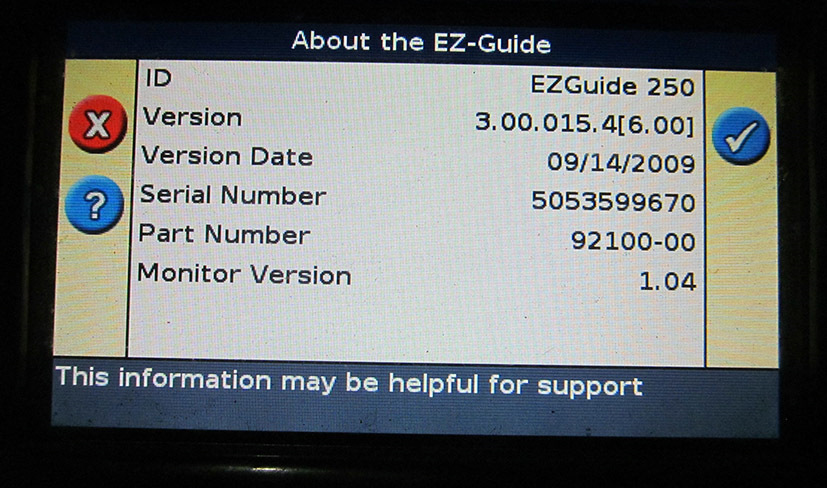
версия ПО
2. Вставляем в выключенный навигатор флешку с языком.
3. Подаём питание на устройство. Включаем навигатор.
4. Он загрузится полностью. Ничего не трогать.

5. Затем, через 5-10 секунд он «увидит » флешку, потом на ней язык и напишет: «loading _russian», «Yes/No»/ В течении 3-5 секунд язык установится и устройство предложит выбрать язык общения «Eng/Рус». Выбираем «Русский » и всё.

6. Готово.
Выключаем, отключаем питание, извлекаем флешку.
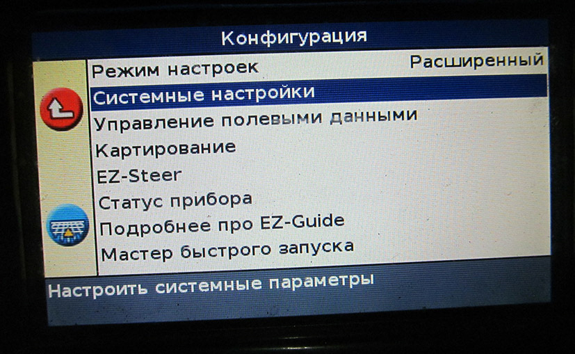

Проверяем, отдаём владельцу.

Ссылка на инструкцию, прошивку, языки «v3_00_-_AgGPS_EZ-Guide_250» disk.yandex.ru/d/e7mbpcG_34HklQ?w=1
Всего наилучшего!
Дополнение.
Еще пришёл агронавигатор Trimble EZ-Guide 250 с проблемой «постоянная перезагрузка агронавигатора». От 3 до 5-8 секунд в рабочем режиме и опять перезагруз. Можно изловчиться и посмотреть версию прошивки.)
Похоже на проблемы с питанием или неисправную флешь S29GL512P10TFIR1.
Но я решил проблему по другому. Жёсткая перезагрузка. (Хотя вскрыл и проверил все напряжения питания 1,5В, 1,8В, 2В, 3,3В — норма)
1. Жесткая перезагрузка системы
Она выполняется так:
1. Выключить EZ-250
2. Зажать одновременно все три кнопки I, II и III, и, не отпуская их, включить прибор.
3. Держать нажатыми кнопки до тех пор, пока индикатор загрузки внизу экрана начнет медленно двигаться. Кнопки можно отпустить.
4. После загрузки системы прибор будет содержать только заводские установки, поэтому потребуется его настройка:
2. Настройки после жесткого перезапуска
1. При стартовом диалоге выбрать:, Metric, WIZARD — NO.
2. Войти в меню настроек, выбрать GPS, Setup, листать экраны до строчки Auto Select, перевести курсор на нее, нажать и выбрать в списке спутник EАSAT. Нажать, стрелкой перейти на надпись Next Screen, нажать, листать до картинки с трактором и пунктом «30 см». – это величина точности которую должен набрать прибор, после которого он позволит включить автопилот. Для ускорения начала работы рекомендуется кнопкой изменить 30 на 150. Нажать. Листать до…
3. Затем установка русского языка. Но я делал по своему способу. Еще вариант, я не пробовал.
Прошивка новой версии.
1. Записать на флэш-память содержимое архива «прошивка EZ-Guide -250» с русской локализацией.
2. При включенном EZGuide-250 вставить флэш-память в разъем на задней стороне прибора.
3. На экране появится сообщение о том, что найдено обновление системных файлов.
Нажать «ОК» для продолжения прошивки или кнопку I для выхода из режима прошивки.
4. При нажатии «ОК» на экран высветится список обновлений. Выбрать версию с наибольшим номером. Нажать «ОК»
5. После каждого обновления прибор перезагрузится.
6. После перезагрузки выбрать:
Единицы измерений – метрические Фильтр OnPath – выключить, если платная дифпоправка, или оставить включенным в соответствии с количеством помех на полях.
Всем удачи!
Содержание
- Система паралельного вождения (навигатор) Trimble EZ-Guide 250, 500, 750 и др.
- Вы здесь
- Страницы
- «Система параллельного вождения Trimble EZ-GUIDE 250 Инструкция по эксплуатации Trimble© ИНСТРУКЦИЯ по эксплуатации курсоуказателя EZ Guide . »
Система паралельного вождения (навигатор) Trimble EZ-Guide 250, 500, 750 и др.
Вы здесь
Страницы
Вопросы задавать можно только после регистрации. Войдите или зарегистрируйтесь, пожалуйста.
Хотелось бы в данной теме обсуждать конкретные ньюансы в:
— настройках (в зависимости от териториального расположения);
— комплектации оборудования (с какой антенной и т.д.)
— прошивках (у кого какая стоит, откуда кто берет новые,шьете ли сами, и т.д.)
— опыту вождения, работе с меню (расширеный режим) может кто-что подметил,
потому как система непростая, и механизатор который с мобильным с трудом
разбирается — с ней сам неразберется ))
Коротко по своему опыту использования. У меня Trimble EZ-Guide 250+антенна AG15, териториально Центральная Украина. Тем у кого внешняя антенна AG15 и кто ближе к старушке Европе в системных настройках выберать режим поправок EGNOS.Если большая поперечная качка то антену ставить чем пониже к земле (на капот). Обрабатывать вначале край — потом механизатору легче на линию заходить и видно где заканчивать работу.
Вопросы, которые меня интересуют:
1) Какой конкретный спутник ставить в настройках поправки EGNOS ? Или оставить автовыбор программе ?
2) Прошивка в приборе версии 3.0 , на оффсайте и на некоторых сайтах российских дилеров видел 3.10. Как правильно прошиваться ? Кто где качал и качает прошивки, потому как качнул с двух сайтов — они разные и по формату файлов и по размеру.
3) Пару раз повисал после запуска, после того как был готов к работе. Сейчас ненаблюдается такого. Ни у кого подобного небыло ?
У меня тоже Тримбл-250, антенна правда штатная,та что идет с прибором.Работаем в «простом» режиме.сигнал спутника ловит достаточно устойчиво.Проблемыу прибора бывают у линий ЛЭП и у плотных лесополос.В остальном пока все устраивает.
В прежней теме удобнее сравнивать. Здесь, уже во втором посту, мы фактически вернулись к этому.
Уважаемый «Kostyash»! Без обид! У нас нет «параллельки», а хочется иметь. И Ваше обсуждение было мне интересно и в той теме.
Но Вам удобнее так. И это вполне объяснимо.
Успехов Вам, и всем держателям Тримбла!
Хотел обновить прошивку — не хочет подгребать флешку. Флешка старая, Apacer 1.2 Gb. Форматировал и под FAT і FAT32 — результат тот же. Прибор пишет что несовместимое устройство. Кто что подскажет ? И кто уже пробовал версию 3.10 ?
Курсовую линию можно удлинить ? Отбил в режиме Идентичная кривая. А один край поля косой — край все время дальше и дальше. Или такое нельзя сделать ?
Что никто с USB устройствами ничего не пробовал на Тримлах ? Может подсказали бы чтоб я пол-магазина флешек не скупал.
с Тримблом 100% работают флэшки A-DATA
8 Гб флэшки пользуем давно. работает.
Хотелось бы в данной теме обсуждать конкретные ньюансы в:
— настройках (в зависимости от териториального расположения);
— комплектации оборудования (с какой антенной и т.д.)
— прошивках (у кого какая стоит, откуда кто берет новые,шьете ли сами, и т.д.)
— опыту вождения, работе с меню (расширеный режим) может кто-что подметил,
потому как система непростая, и механизатор который с мобильным с трудом
разбирается — с ней сам неразберется ))
Коротко по своему опыту использования. У меня Trimble EZ-Guide 250+антенна AG15, териториально Центральная Украина. Тем у кого внешняя антенна AG15 и кто ближе к старушке Европе в системных настройках выберать режим поправок EGNOS.Если большая поперечная качка то антену ставить чем пониже к земле (на капот). Обрабатывать вначале край — потом механизатору легче на линию заходить и видно где заканчивать работу.
Вопросы, которые меня интересуют:
1) Какой конкретный спутник ставить в настройках поправки EGNOS ? Или оставить автовыбор программе ?
2) Прошивка в приборе версии 3.0 , на оффсайте и на некоторых сайтах российских дилеров видел 3.10. Как правильно прошиваться ? Кто где качал и качает прошивки, потому как качнул с двух сайтов — они разные и по формату файлов и по размеру.
3) Пару раз повисал после запуска, после того как был готов к работе. Сейчас ненаблюдается такого. Ни у кого подобного небыло ?
По системам.
Каждый пользует что больше нравится и на сколько позволяет бюджет.
Рекомендую все же Тримбл (в частности если начальную систему — то Тримбл 250 = самое оптимальное соотношение цена/качество/надежность/функционал).
Освоить систему не составляет труда механизатору за 20-30 минут. Если конечно он умеет кнопки нажимать (т.е. к примеру у него есть сотовый телефон).
В простом режиме (расширенный — для администратора) пользователь выбирает рабочие параметры (ширина агрегата, перекрытие и т.д.), яркость дисплея, шаблоны движения — сможет школьник начальных классов.
По настройке GPS сигнала — если у вас EGNOS работает нестабильно — -> выбирайте без поправок = пусть погрешность будет немного больше, зато постоянный уверенный прием гарантирован.
По рельефу — если у вас выраженный рельеф (склоны, балки) = размещением антенны на капоте проблему не решить, тем более есть вероятность затенения сигнала спутников кабиной трактора.
В таком случае лучше приобретать и устанавливать подруливающее устройство (в составе идет систем компенсации рельефа).
По прошивке — w ww. trimble .com — официальный сайт Тримбл. там есть все. в т.ч. последние версии прошивок (прошивка (*.img) и язык (*.lpf)). прошивку 3.10
по зависаниям — если нестабильное питание, подключенией не к аккумулятору (аккумуляторной цепи).
рекомендую сделать общий сброс — и перепрошить последней прошивкой.
Источник
«Система параллельного вождения Trimble EZ-GUIDE 250 Инструкция по эксплуатации Trimble© ИНСТРУКЦИЯ по эксплуатации курсоуказателя EZ Guide . »
Система параллельного вождения
Trimble EZ-GUIDE 250
Инструкция по эксплуатации
по эксплуатации курсоуказателя EZ Guide 250
прошивка версии 3.00.047
1. Внешний вид и органы управления EZ-Guide 250
Светодиоды -индикаторы курсоуказателя
(оранжевый — готов к работе, уже в работе красный
три зеленых – вождение идет точно по Рабочие клавиши
осуществляется удержакнием Кнопка кнопки в Включение/выключе течение 3 секунд.
ние прибора Кнопки Кнопка С помощью выбирается Кнопка нужная иконка.
Принимает разные С помощью значения в разных — подтверждение экранах.
Элементы интерфейса Отклонение от Маркер Скорость Иконки Информационные курса показывает предназначены сообщения, текущее для выбора включая ошибки положение режимов работы трактора на Оранжевый линии квадратик отмечает, ту иконку, где находится курсор Обратная сторона EZ Guide 250 Порт для подключения Порт питания и USB-устройства внешнего контроллера Разъем для антенны Посадочное место для крепления
2. ОПИСАНИЕ ИКОНОК, которые появляются на экране в процессе работы с левой и
ООО «Кубанские Информационные технологии» © Copyright 2007г. Стр. из 15 4
3. НАЧАЛО РАБОТЫ
3.1. ПРИ ВКЛЮЧЕНИИ ПРИБОРА – выбрать правильную систему измерений
3.2. Дождаться появления зеленого значка спутника в левом верхнем углу экрана Индикатор качества сигнала GPS
— Если иконка спутника горит красным – сигнал GPS отсутствует.
Если после включения прошло более 15 минут и сигнал горит красным, то возможная причина: нет контакта в разъеме антенны, вокруг находятся здания или высокие деревья лесополосы, антенна закрыта каким-то предметом.
— Если иконка спутника горит желтым – сигнал GPS есть, но точность мала, и необходимо подождать.
— Если иконка спутника горит зеленым – GPS точность достаточна. Можно работать. Если в течение 15 мин сигнал не загорается, возможной причиной являются: наличие лесополосы, зданий, конструкций, которые являются препятствием для прохождения сигнала дифференциальной коррекции EGNOS c юга. В этом случае необходимо переехать на открытое место.
В EZ-Guide 250 возможно сохранить отчет по каждому полю в формате.rtf (открывается в Микрософт Ворд или ином текстовом редакторе высокого уровня). Для этого надо выбрать пункт «Сводные отчеты » в меню «Управление полевыми данными», и там выбрать пункт «Послать сводные отчеты на USB».
После этого будет предложено меню выбора, и в нем можно выбрать Клиента (будут сохранены все поля для Клиента), Хозяйство (все поля в данном хозяйстве), или одно конкретное поле.
Информация будет сохранена на флэш-карту в формате:
AgGPSDataИмя_клиентаИмя_Хозяйстваномер_поля.
Внутри папки «номер_поля» (например, AgGPS/Data/Default_Client/Default_Farm/ 0000EZ06739) будут лежать файлы разного формата, и папка Event_0000-2000_0001_EZ06739, внутри которой будет файл EventSummary.rtf.
Он будет содержать сводный отчет по выбранному полю:
все заданные значения (имя поля, хозяйства, фамилия оператора, GPS-координаты, дата обработки и т.д.), и схему движения по полю, со всеми огрехами и перекрытиями, отмеченными точками и т.д.
6. ПОЯСНЕНИЯ Светодиоды — Индикаторы навигатора Три зеленых светодиода над экраном означают верный курс трактора. Если трактор отклонился от идеального курса – светодиоды убегают влево или вправо и загораются красным цветом, указывая, направление и величину отклонения, чтобы водитель мог учесть это при подруливании.
Индикаторы разворота мигают, когда трактор проезжает по участку, который считается обработанным (по которому уже проезжали), сигнализируя, что необходимо поднять агрегат и сделать разворот.
Функциональные кнопки Кнопки I, II и III при нажатии сразу включают функцию, обозначенную иконкой рядом с кнопкой.
Кнопка I вызывает на экран полупрозрачное зеленое окошко с информацией. Первым нажатием вызывается окно с информацией по полю, вторым – по сигналу GPS, и третьим – по EZ-Steer. Четвертое нажатие кнопки I убирает окно информации.
Кнопка II включает и выключает режим записи работы. Во включенном состоянии агрегат считается опущенным, идет подсчет гектаров, а на экране за трактором остается желтая полоса обработанной земли. В выключенном состоянии агрегат считается поднятым, подсчет гектаров остановлен, на экране желтая полоса не отображается.
Для удаления полей:
1. Выбрать кнопками или иконку. Выбрать пункт Управление данными, выбрать в нем пункт Удалить поля.
2. В таблице будут три строчки, позволяющие удалять как все, относящееся к клиенту Клиент, так и отдельные поля (Хозяйство, поле). При этом в строчке Хозяйство будет отображаться нумерация группы полей (последних две цифры). Подвести курсор к строчке Клиент, нажать, нажать кнопку, курсор прыгнет вверх на надпись ALL. Нажать.. Появится просьба подождать и вернется предыдущий экран, но в строчке Farm последняя цифра уменьшится на единицу.
Повторять эту операцию до тех пор, пока не удалятся все поля.
Жесткая перезагрузка системы
В случае, если это не помогает, необходима жесткая перезагрузка системы. Она выполняется так:
1. Выключить EZ-250
2. Зажать одновременно все три кнопки I, II и III, и, не отпуская их, включить прибор.
3. Держать нажатыми кнопки до тех пор, пока индикатор загрузки внизу экрана начнет медленно двигаться. Кнопки можно отпустить.
ООО «Кубанские Информационные технологии» © Copyright 2007г. Стр. из 15 14
4. После загрузки системы прибор будет содержать только заводские установки, поэтому потребуется его настройка:
Настройки после жесткого перезапуска
1. При стартовом диалоге выбрать:, Metric, WIZARD — NO.
2. Войти в меню настроек, выбрать GPS, Setup, листать экраны до строчки Auto Select, перевести курсор на нее, нажать и выбрать в списке спутник EАSAT. Нажать, стрелкой перейти на надпись Next Screen, нажать, листать до картинки с трактором и пунктом «30 см». – это величина точности которую должен набрать прибор, после которого он позволит включить автопилот. Для ускорения начала работы рекомендуется кнопкой изменить 30 на 150. Нажать. Листать до
Прошивка новой версии.
1. Записать на флэш-память содержимое архива «прошивка EZ-Guide -250» с русской локализацией.
2. При включенном EZGuide-250 вставить флэш-память в разъем на задней стороне прибора.
3. На экране появится сообщение о том, что найдено обновление системных файлов.
Нажать «ОК» для продолжения прошивки или кнопку I для выхода из режима прошивки.
4. При нажатии «ОК» на экран высветится список обновлений. Выбрать версию с наибольшим номером. Нажать «ОК»
5. После каждого обновления прибор перезагрузится
6. После перезагрузки выбрать:
Единицы измерений – метрические Фильтр OnPath – выключить, если платная дифпоправка, или оставить включенным в соответствии с количеством помех на полях.
 «Автор доклада ОАО «Гипротюменнефтегаз» Создан в 1964 году Запроектировано более 250 месторождений нефти, газа и газоконденсата Численность 1070 чел. в т.ч.: проектировщиков – 482 чел.изыскателей – 350 чел.научные лаборатории – 57 чел. Объем работ в 2006 г. – 1306 млн.руб.в т.ч. с. »
«1 Лекция 27 (Окончание) 2. ФИЗИЧЕСКИЕ ОСНОВЫ ЯДЕРНОГО СИНТЕЗА 2.1 Термодинамика ядерного синтеза То, что ядерные реакции синтеза могут давать высокий энергетический выигрыш понятно не только из астрономических данных. Достаточно взглянуть на график зависимости энергии связи от массового числа, А. График имеет максимум. »
«Предложения вузов в проект Стратегии развития молодежи Российской Федерации на период до 2025 года 27 вузов № ВУЗ Содержание предложения Примечание п/п Астраханский государственный Дополнить проект Стратегии. Учтено 1. университе. »
«УДК 81’373.45 А. Н. Шумакова канд. филол. наук, доц. каф. лингвистики и профессиональной коммуникации в области политических наук ИМО и СПН МГЛУ; e-mail: ashumakova@yandex.ru О ЗАИМСТВОВАНИЯХ ИЗ АНГЛИЙСКОГО ЯЗЫКА В СОВРЕ. »
«Водлозеро. Трифон Суханов XXXVII ТРИФОН СУХАНОВ Трифон Иванович Суханов, крестьянин с Охтом-острова на Водлозере, 70 лет, здоровый, моложавый, еще несущий тягло и занимающийся доселе полесничеством. Перенял былины от отца, который умер под 100 лет. »
«РУКОВОДСТВО ПОЛЬЗОВАТЕЛЯ GSM modem iRZ TC65i-485Gl Содержание 1. Введение 1.1. Описание документа 1.2. Служебная информация 1.3. Правила безопасности 2. Общая информация 2.1. Назначение устройства 2.2. Комплектация. »
«95 Исследовательский журнал русского языка и литературы, 1(2), 2013, Cc. 95-107 Философская ментальность Востока в русской поэзии XIX века Масуме Мотамедния Преподаватель Мазандранского университета, Б. »
«1 2 3 4 ПОЛЕВОЕ РУКОВОДСТВО ПО СНИЖЕНИЮ ВРЕДА ПРАВА ЧЕЛОВЕКА Документирование и адвокация РУКОВОДСТВО ДЛЯ ОРГАНИЗАЦИЙ ЛЮДЕЙ, КОТОРЫЕ УПОТРЕБЛЯЮТ НАРКОТИКИ МЕЖДУНАРОДНАЯ ПРОГРАММА СНИЖЕНИЯ ВРЕДА (IHRD) ПОЛЕВОЕ РУКОВОДСТВО ПО СНИЖЕНИЮ ВРЕДА 1 ПРАВА ЧЕЛОВЕКА Документирование и адвокация. »
«РУССКАЯ СТАРИНА ЕЖЕМСЯЧНОЕ И С Т О Р И Ч Е С К О Е ИЗДАНІ Е я: ы в ь ГмъХХіІМ. а 1897 га д ъ СОДЕРЖАНІЕ: L Таганрогъ въ 1825 году.. X. Зависима вннвша „РуссвоВ IL Б. Ш в 2 г д е f t. Ствроны*: О рагваиыиВ шАшсчвдъ ва журналъ. IL Камни Маріа MammniСообщ. A. »
2017 www.net.knigi-x.ru — «Бесплатная электронная библиотека — электронные матриалы»
Материалы этого сайта размещены для ознакомления, все права принадлежат их авторам.
Если Вы не согласны с тем, что Ваш материал размещён на этом сайте, пожалуйста, напишите нам, мы в течении 1-2 рабочих дней удалим его.
Источник