

Американская компания Chauvet выпустила целую серию портативных DMX контроллеров управления светом. Chauvet-DJ Obey — представляет собой линейку интеллектуальных пультов управления световыми приборами для малых и средних заведений и мероприятий. Серия Obey включает в себя следующий модельный ряд: Obey 3, Obey 4, Obey 6, Obey 10, Obey 40, Obey 50, Obey 70. Они прекрасно подходят для различных кафе, баров, ресторанов, дискоклубов, малых и средних концертных залов, свадеб, фото и видеосъемочных площадок, малых и средних концертов Open Air и так далее.
Obey 40 — представляет собой универсальный DMX контроллер управления интеллектуальным светом на 192 DMX канала. Данный контроллер позволяет независимо управлять 12 световыми приборами по 16 каналов на каждый. Он имеет 30 банков по 8 сцен в каждом, соответственно всего 240 сцен. Может работать как в ручном, так и автоматическом режиме. Плюс ко всему, данная модель имеет выход на стробоскоп, а так же выход на дымогенератор. Так же на задней панели имеется MIDI-вход. Очень удобным является цифровой дисплей, на котором отображается информация о текущем режиме работы контроллера. К тому же он имеет корпус рэкового исполнения размером в 19″ (дюймов) и 3U (юнита), что позволяет монтировать его в рэковую стойку.
Данная модель прибора может использоваться в самых различных заведениях и мероприятиях. Например это могут быть: кафе, бары, рестораны, караоке клубы, небольшие дискоклубы, фотостудии, видеосъемочные площадки и так далее.
Подробное описание
Схема подключения активных приборов к Chauvet Obey 40

Схема подключения пассивных приборов к Chauvet Obey 40

| Тип: | DMX контроллер |
| Каналов DMX: | 192 |
| Независимо управляемых источников: | 12 по 16 каналов в каждом |
| Наборов эффектов: | 30 банков по 8 сцен в каждом |
| Всего сцен: | 240 |
| Автоматический режим: | есть |
| Цифровой дисплей: | есть |
| Управление стробоскопом: | есть |
| Управление дымогенератором: | есть |
| MIDI вход: | 5 DIN |
| DMX выход: | 3-pin XLR |
| Выход на стробоскоп: | Jack |
| Выход на дымогенератор: | 5 DIN |
| Фейдеров: | 10 |
| Источник питания: | блок питания 9В, 500мА |
| Исполнение: | рэковое 19″ 3U |
| Вес: | 2.6 кг |
| Размеры: | 483х89х171 мм |
| Контроллер: | 1 шт. |
| Блок питания: | 1 шт. |
Дополнительно
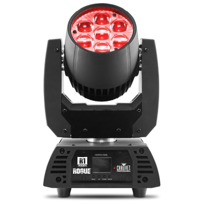
Wash, 7 светодиодов RGBW по 15 Вт/980 мА (50 000 часов работы), цветовая температура от 2800 до 10000 к, управление DMX, RDM, размеры 187 x 265 x 354 мм, вес 5,9 кг.
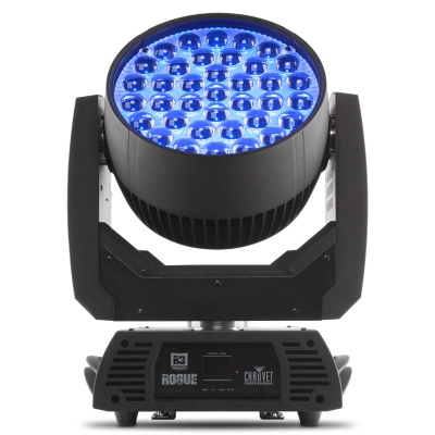
Wash, 37 светодиодов RGBW по 15 Вт/980 мА (50 000 часов работы), цветовая температура от 2800 до 10000 к, управление DMX, RDM, размеры 394 x 298 x 470 мм, вес 17,46 кг.

Spot, 1 светодиод 440 Вт/5.6 A (6808 K), 50000 часов работы, управление Art-Net, sACN, DMX, W-DMX, DMX (24 или 32 канал), размеры 385 х 250 х 671 мм, вес 28,5 кг.
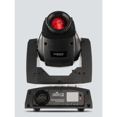
Spot, 1 светодиод 60 Вт/2,3 A, 50000 часов работы, управление DMX (8 или 13 канал), Угол пучка 15°, Частота PWM 1200 Гц, Освещенность 10420 Лк при 2 м, Наклон / уклон 540 ° / 270 °, цвет корпуса черный, размеры 211 x 232 x 337 мм, вес 5,7 кг.

Spot, 1 светодиод 150 Вт/12,3 A, 50000 часов работы, управление DMX (9 или 15 канал), Угол маштабирования 10° до 23°, Частота PWM 1800 Гц, Освещенность 10°-38000 Лк при 2 м, Освещенность 23°-19850 Лк при 2 м, Наклон / уклон 540 ° / 270 °, цвет черный, размеры 220 x 322 x 466 мм, вес 12,4 кг.
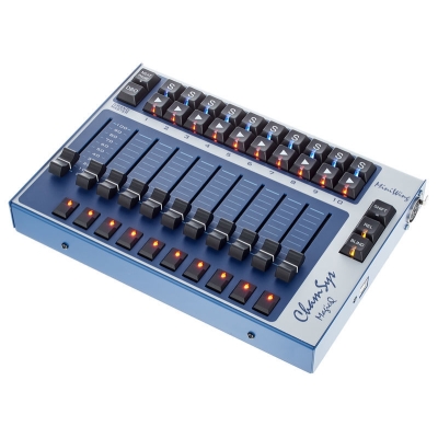
Универсальный DMX-контроллер, поддержка платформ Mac OS X/Windows/Linux, работа на программном обеспечении MagicQ PC, управление световым и видеооборудованием, возможность сохранения шоу на USB накопители, подключение к компьютеру по USB, DMX-выход 5-pin XLR (без ограничений по патчу), поставляется в пластиковом кейсе, питание по шине USB.

User Manual

|
TABLE OF CONTENTS |
|
|
1. Before You Begin………………………………………………………………………………………………………………………………… |
10 |
|
What Is Included …………………………………………………………………………………………………………………………………………………………. |
10 |
|
Unpacking Instructions ………………………………………………………………………………………………………………………………………………… |
10 |
|
Claims …………………………………………………………………………………………………………………………………………………………………… |
10 |
|
Conventions ……………………………………………………………………………………………………………………………………………………………….. |
10 |
|
Symbols……………………………………………………………………………………………………………………………………………………………………… |
10 |
|
Disclaimer…………………………………………………………………………………………………………………………………………………………………… |
10 |
|
Product at a Glance…………………………………………………………………………………………………………………………………………………….. |
11 |
|
Safety Notes……………………………………………………………………………………………………………………………………………………………….. |
11 |
|
2. Introduction…………………………………………………………………………………………………………………………………………. |
12 |
|
Features …………………………………………………………………………………………………………………………………………………………………….. |
12 |
|
Product Description …………………………………………………………………………………………………………………………………………………….. |
12 |
|
Mounting…………………………………………………………………………………………………………………………………………………………………….. |
12 |
|
Mounting Dimensions …………………………………………………………………………………………………………………………………………….. |
12 |
|
Programming Concepts ………………………………………………………………………………………………………………………………………………. |
12 |
|
Front Panel Overview………………………………………………………………………………………………………………………………………………….. |
13 |
|
Front Panel View…………………………………………………………………………………………………………………………………………………………. |
13 |
|
Front Panel Controls………………………………………………………………………………………………………………………………………………. |
13 |
|
Control Descriptions……………………………………………………………………………………………………………………………………………….. |
14 |
|
Back Panel View…………………………………………………………………………………………………………………………………………………………. |
16 |
|
Back Panel Ports……………………………………………………………………………………………………………………………………………………. |
16 |
|
DMX Polarity Switch Diagram ……………………………………………………………………………………………………………………………. |
16 |
|
3. Setup…………………………………………………………………………………………………………………………………………………… |
17 |
|
AC Power …………………………………………………………………………………………………………………………………………………………………… |
17 |
|
Mounting…………………………………………………………………………………………………………………………………………………………………….. |
17 |
|
Setting Up The Board………………………………………………………………………………………………………………………………………………….. |
17 |
|
DMX Cabling………………………………………………………………………………………………………………………………………………………………. |
17 |
|
DMX Cabling Diagram……………………………………………………………………………………………………………………………………………. |
17 |
|
DMX Addressing…………………………………………………………………………………………………………………………………………………………. |
18 |
|
DMX Addressing Chart…………………………………………………………………………………………………………………………………………… |
18 |
|
Faders and Pages ………………………………………………………………………………………………………………………………………………………. |
18 |
|
Fader DMX Addresses………………………………………………………………………………………………………………………………………………… |
18 |
|
Fader Customizations………………………………………………………………………………………………………………………………………………….. |
19 |
|
Creating A Fader Assignment…………………………………………………………………………………………………………………………………. |
19 |
|
Copying A Fader Assignment …………………………………………………………………………………………………………………………………. |
20 |
|
Creating A Fader Reversal……………………………………………………………………………………………………………………………………… |
20 |
|
Resetting The Board……………………………………………………………………………………………………………………………………………………. |
20 |
|
4. Programming………………………………………………………………………………………………………………………………………. |
21 |
|
Program Mode ……………………………………………………………………………………………………………………………………………………………. |
21 |
|
Entering Program Mode …………………………………………………………………………………………………………………………………………. |
21 |
|
Exiting Program Mode ……………………………………………………………………………………………………………………………………………. |
21 |
|
I. Programming Lights …………………………………………………………………………………………………………………………………………………. |
21 |
|
Programming Two Products……………………………………………………………………………………………………………………………………. |
22 |
|
II. Programming Scenes………………………………………………………………………………………………………………………………………………. |
23 |
|
Creating A Scene…………………………………………………………………………………………………………………………………………………… |
23 |
|
Deleting A Scene …………………………………………………………………………………………………………………………………………………… |
24 |
|
Deleting A Bank of Scenes……………………………………………………………………………………………………………………………………… |
24 |
|
Deleting All Scenes………………………………………………………………………………………………………………………………………………… |
24 |
|
III. Programming Chases …………………………………………………………………………………………………………………………………………….. |
25 |
|
Page 2 of 160 |
Obey™ 40 User Manual Rev. 7 |

|
Creating A Chase From Individual Scenes………………………………………………………………………………………………………………. |
25 |
|
Creating A Chase From A Bank Of Scenes……………………………………………………………………………………………………………… |
26 |
|
Modifying A Chase…………………………………………………………………………………………………………………………………………………. |
27 |
|
Adding A Step To A Chase………………………………………………………………………………………………………………………………… |
27 |
|
Deleting A Step From A Chase………………………………………………………………………………………………………………………….. |
28 |
|
Deleting A Chase …………………………………………………………………………………………………………………………………………………… |
28 |
|
Deleting All Chases………………………………………………………………………………………………………………………………………………… |
28 |
|
5. Playback……………………………………………………………………………………………………………………………………………… |
29 |
|
Playback Mode …………………………………………………………………………………………………………………………………………………………… |
29 |
|
Scene Playback ………………………………………………………………………………………………………………………………………………………….. |
29 |
|
Manual Scene Playback…………………………………………………………………………………………………………………………………………. |
29 |
|
Auto Scene Playback……………………………………………………………………………………………………………………………………………… |
30 |
|
Auto Scene Playback Using Tap-Sync……………………………………………………………………………………………………………….. |
30 |
|
Music Scene Playback …………………………………………………………………………………………………………………………………………… |
30 |
|
Chase Playback………………………………………………………………………………………………………………………………………………………….. |
31 |
|
Auto Chase Playback …………………………………………………………………………………………………………………………………………….. |
31 |
|
Auto Chase Playback Using Tap Sync……………………………………………………………………………………………………………….. |
31 |
|
Music Chase Playback …………………………………………………………………………………………………………………………………………… |
31 |
|
MIDI Operation……………………………………………………………………………………………………………………………………………………………. |
32 |
|
MIDI Map ………………………………………………………………………………………………………………………………………………………………. |
32 |
|
Fog Control…………………………………………………………………………………………………………………………………………………………………. |
33 |
|
Strobe Control…………………………………………………………………………………………………………………………………………………………….. |
33 |
|
6. Technical Information………………………………………………………………………………………………………………………….. |
34 |
|
Maintenance……………………………………………………………………………………………………………………………………………………………….. |
34 |
|
Technical Specifications………………………………………………………………………………………………………………………………………………. |
34 |
|
Returns…………………………………………………………………………………………………………………………………………………… |
35 |
|
Contact Us………………………………………………………………………………………………………………………………………………. |
36 |
|
1. Antes de Empezar……………………………………………………………………………………………………………………………….. |
37 |
|
Qué va Incluido …………………………………………………………………………………………………………………………………………………………… |
37 |
|
Instrucciones de Desembalaje……………………………………………………………………………………………………………………………………… |
37 |
|
Reclamaciones………………………………………………………………………………………………………………………………………………………. |
37 |
|
Convenciones …………………………………………………………………………………………………………………………………………………………….. |
37 |
|
Símbolos…………………………………………………………………………………………………………………………………………………………………….. |
37 |
|
Exención de Responsabilidad ……………………………………………………………………………………………………………………………………… |
37 |
|
El Producto de un Vistazo……………………………………………………………………………………………………………………………………………. |
38 |
|
Notas de Seguridad…………………………………………………………………………………………………………………………………………………….. |
38 |
|
2. Introducción………………………………………………………………………………………………………………………………………… |
39 |
|
Características ……………………………………………………………………………………………………………………………………………………………. |
39 |
|
Descripción del Producto …………………………………………………………………………………………………………………………………………….. |
39 |
|
Montaje………………………………………………………………………………………………………………………………………………………………………. |
39 |
|
Dimensiones de Montaje………………………………………………………………………………………………………………………………………… |
39 |
|
Conceptos de Programación ……………………………………………………………………………………………………………………………………….. |
40 |
|
Vista General del Panel Frontal……………………………………………………………………………………………………………………………………. |
41 |
|
Visa del Panel Frontal …………………………………………………………………………………………………………………………………………………. |
41 |
|
Controles del Panel Frontal…………………………………………………………………………………………………………………………………….. |
42 |
|
Descripciones del Control……………………………………………………………………………………………………………………………………….. |
42 |
|
Vista del Panel Posterior……………………………………………………………………………………………………………………………………………… |
44 |
|
Puertos del Panel Posterior…………………………………………………………………………………………………………………………………….. |
44 |
|
Diagrama de Conmutador de Polaridad DMX …………………………………………………………………………………………………….. |
44 |
|
3. Configuración……………………………………………………………………………………………………………………………………… |
45 |
|
Corriente Alterna…………………………………………………………………………………………………………………………………………………………. |
45 |
|
Obey™ 40 User Manual Rev. 7 |
Page 3 of 160 |

|
Montaje………………………………………………………………………………………………………………………………………………………………………. |
45 |
|
Instalación de la Mesa…………………………………………………………………………………………………………………………………………………. |
45 |
|
Cableado DMX……………………………………………………………………………………………………………………………………………………………. |
45 |
|
Diagrama de Cableado DMX………………………………………………………………………………………………………………………………….. |
45 |
|
Asignación de Direcciones DMX ………………………………………………………………………………………………………………………………….. |
46 |
|
Tabla de Asignación de Direcciones DMX……………………………………………………………………………………………………………….. |
46 |
|
Deslizadores y Páginas……………………………………………………………………………………………………………………………………………….. |
46 |
|
Direcciones DMX del Deslizador………………………………………………………………………………………………………………………………….. |
47 |
|
Personalización del Deslizador…………………………………………………………………………………………………………………………………….. |
47 |
|
Crear una Asignación de Deslizador……………………………………………………………………………………………………………………….. |
48 |
|
Copiar una Asignación del Deslizador …………………………………………………………………………………………………………………….. |
49 |
|
Crear una Inversión de Deslizador ………………………………………………………………………………………………………………………….. |
49 |
|
Reiniciar la Mesa ………………………………………………………………………………………………………………………………………………………… |
49 |
|
4. Programación ……………………………………………………………………………………………………………………………………… |
50 |
|
Modo Programa ………………………………………………………………………………………………………………………………………………………….. |
50 |
|
Entrar en el Modo Programa…………………………………………………………………………………………………………………………………… |
50 |
|
Salir del Modo de Programa …………………………………………………………………………………………………………………………………… |
50 |
|
I. Programar las Luces ………………………………………………………………………………………………………………………………………………… |
50 |
|
Programar dos Productos ………………………………………………………………………………………………………………………………………. |
51 |
|
II. Programar Escenas…………………………………………………………………………………………………………………………………………………. |
52 |
|
Crear una Escena ………………………………………………………………………………………………………………………………………………….. |
52 |
|
Borrar una Escena…………………………………………………………………………………………………………………………………………………. |
53 |
|
Borrar un Banco de Escenas ………………………………………………………………………………………………………………………………….. |
54 |
|
Borrar Todas las Escenas ………………………………………………………………………………………………………………………………………. |
54 |
|
III. Programar Secuencias……………………………………………………………………………………………………………………………………………. |
55 |
|
Crear una Secuencia a Partir de Escenas Individuales…………………………………………………………………………………………….. |
55 |
|
Crear una Secuencia a Partir de un Banco de Escenas …………………………………………………………………………………………… |
56 |
|
Modificar una Secuencia ………………………………………………………………………………………………………………………………………… |
57 |
|
Añadir un Paso a una Secuencia……………………………………………………………………………………………………………………….. |
57 |
|
Borrar un Paso de una Secuencia……………………………………………………………………………………………………………………… |
58 |
|
Borrar una Secuencia…………………………………………………………………………………………………………………………………………….. |
58 |
|
Borrar Todas las Secuencias………………………………………………………………………………………………………………………………….. |
58 |
|
5. Reproducción ……………………………………………………………………………………………………………………………………… |
59 |
|
Modo Reproducción ……………………………………………………………………………………………………………………………………………………. |
59 |
|
Reproducción de Escena…………………………………………………………………………………………………………………………………………….. |
59 |
|
Reproducción Manual de Escena……………………………………………………………………………………………………………………………. |
59 |
|
Reproducción Automática de Escena ……………………………………………………………………………………………………………………… |
60 |
|
Reproducción Automática de Escena Usando Sincronización al Toque……………………………………………………………….. |
60 |
|
Reproducción de Escena por Música………………………………………………………………………………………………………………………. |
60 |
|
Reproducción de Secuencia………………………………………………………………………………………………………………………………………… |
61 |
|
Reproducción Automática de Secuencia …………………………………………………………………………………………………………………. |
61 |
|
Reproducción Automática de Secuencia Usando Sincronización al Toque…………………………………………………………… |
61 |
|
Reproducción de Secuencia por Música………………………………………………………………………………………………………………….. |
61 |
|
Funcionamiento MIDI ………………………………………………………………………………………………………………………………………………….. |
62 |
|
Mapa MIDI …………………………………………………………………………………………………………………………………………………………….. |
62 |
|
Control de Niebla ………………………………………………………………………………………………………………………………………………………… |
63 |
|
Control de Estroboscopio…………………………………………………………………………………………………………………………………………….. |
63 |
|
6. Información Técnica ……………………………………………………………………………………………………………………………. |
64 |
|
Mantenimiento…………………………………………………………………………………………………………………………………………………………….. |
64 |
|
Especificaciones Técnicas…………………………………………………………………………………………………………………………………………… |
64 |
|
Devoluciones………………………………………………………………………………………………………………………………………….. |
65 |
|
Page 4 of 160 |
Obey™ 40 User Manual Rev. 7 |

|
Contacto…………………………………………………………………………………………………………………………………………………. |
66 |
|
1. Avant de Commencer………………………………………………………………………………………………………………………….. |
67 |
|
Contenu ……………………………………………………………………………………………………………………………………………………………………… |
67 |
|
Instructions de Déballage…………………………………………………………………………………………………………………………………………….. |
67 |
|
Réclamations…………………………………………………………………………………………………………………………………………………………. |
67 |
|
Conventions ……………………………………………………………………………………………………………………………………………………………….. |
67 |
|
Symboles……………………………………………………………………………………………………………………………………………………………………. |
67 |
|
Clause de non Responsabilité……………………………………………………………………………………………………………………………………… |
67 |
|
Bref Descriptif de l’Unité ………………………………………………………………………………………………………………………………………………. |
68 |
|
Consignes de Sécurité ………………………………………………………………………………………………………………………………………………… |
68 |
|
2. Introduction…………………………………………………………………………………………………………………………………………. |
69 |
|
Caractéristiques ………………………………………………………………………………………………………………………………………………………….. |
69 |
|
Description de l’Appareil………………………………………………………………………………………………………………………………………………. |
69 |
|
Installation…………………………………………………………………………………………………………………………………………………………………… |
69 |
|
Dimensions de Montage…………………………………………………………………………………………………………………………………………. |
69 |
|
Concept de Programmation…………………………………………………………………………………………………………………………………………. |
69 |
|
Vue d’Ensemble du Panneau Frontal …………………………………………………………………………………………………………………………… |
70 |
|
Vue du Panneau Frontal ……………………………………………………………………………………………………………………………………………… |
70 |
|
Commandes du Panneau Avant……………………………………………………………………………………………………………………………… |
71 |
|
Description des Commandes………………………………………………………………………………………………………………………………….. |
71 |
|
Vue du Panneau Arrière………………………………………………………………………………………………………………………………………………. |
74 |
|
Ports du Panneau Arrière……………………………………………………………………………………………………………………………………….. |
74 |
|
Schéma du Commutateur de Polarité DMX………………………………………………………………………………………………………… |
74 |
|
3. Configuration………………………………………………………………………………………………………………………………………. |
75 |
|
Alimentation CA ………………………………………………………………………………………………………………………………………………………….. |
75 |
|
Installation…………………………………………………………………………………………………………………………………………………………………… |
75 |
|
Configuration de la Console…………………………………………………………………………………………………………………………………………. |
75 |
|
Câblage DMX……………………………………………………………………………………………………………………………………………………………… |
75 |
|
Schéma de Câblage DMX………………………………………………………………………………………………………………………………………. |
75 |
|
Configuration des Adresses DMX ………………………………………………………………………………………………………………………………… |
76 |
|
Tableau d’Adressage DMX …………………………………………………………………………………………………………………………………….. |
76 |
|
Potentiomètres et Pages……………………………………………………………………………………………………………………………………………… |
76 |
|
Adresses DMX des Potentiomètres ……………………………………………………………………………………………………………………………… |
77 |
|
Personnalisations des Potentiomètres………………………………………………………………………………………………………………………….. |
77 |
|
Création d’Une Affectation de Potentiomètre……………………………………………………………………………………………………………. |
78 |
|
Copie d’Une Affectation de Potentiomètre ……………………………………………………………………………………………………………….. |
79 |
|
Création d’Une Inversion de Potentiomètre ……………………………………………………………………………………………………………… |
79 |
|
Réinitialisation de la Console……………………………………………………………………………………………………………………………………….. |
79 |
|
4. Programmation……………………………………………………………………………………………………………………………………. |
80 |
|
Mode Programmation………………………………………………………………………………………………………………………………………………….. |
80 |
|
Entrer Dans le Mode Programmation………………………………………………………………………………………………………………………. |
80 |
|
Sortir du Mode Programmation……………………………………………………………………………………………………………………………….. |
80 |
|
I. Programmation des Projecteurs………………………………………………………………………………………………………………………………… |
81 |
|
Programmation de Deux Appareils………………………………………………………………………………………………………………………….. |
82 |
|
II. Programmation des Scènes …………………………………………………………………………………………………………………………………….. |
83 |
|
Créer une Scène……………………………………………………………………………………………………………………………………………………. |
83 |
|
Supprimer une Scène…………………………………………………………………………………………………………………………………………….. |
84 |
|
Supprimer une Banque de Scènes………………………………………………………………………………………………………………………….. |
85 |
|
Supprimer Toutes les Scènes…………………………………………………………………………………………………………………………………. |
85 |
|
III. Programmation des Chenillards ………………………………………………………………………………………………………………………………. |
86 |
|
Création d’un Chenillard à Partir des Scènes Individuelles ……………………………………………………………………………………….. |
86 |
|
Obey™ 40 User Manual Rev. 7 |
Page 5 of 160 |

|
Création d’un Chenillard à Partir d’une Banque de Scènes……………………………………………………………………………………….. |
87 |
|
Modifier un Chenillard…………………………………………………………………………………………………………………………………………….. |
88 |
|
Ajouter un Pas à un Chenillard…………………………………………………………………………………………………………………………… |
88 |
|
Supprimer un Pas d’un Chenillard ……………………………………………………………………………………………………………………… |
89 |
|
Supprimer un Chenillard…………………………………………………………………………………………………………………………………………. |
90 |
|
Supprimer Tous les Chenillards………………………………………………………………………………………………………………………………. |
90 |
|
5. Lecture………………………………………………………………………………………………………………………………………………… |
91 |
|
Mode Lecture ……………………………………………………………………………………………………………………………………………………………… |
91 |
|
Lecture de Scène………………………………………………………………………………………………………………………………………………………… |
91 |
|
Lecture Manuelle de Scène ……………………………………………………………………………………………………………………………………. |
92 |
|
Lecture Automatique de Scène……………………………………………………………………………………………………………………………….. |
93 |
|
Lecture Automatique de Scène en Utilisant la Fonction Tap-Sync ……………………………………………………………………….. |
93 |
|
Lecture de Scène par la Musique……………………………………………………………………………………………………………………………. |
93 |
|
Lecture de Chenillards…………………………………………………………………………………………………………………………………………………. |
94 |
|
Lecture Automatique de Chenillard …………………………………………………………………………………………………………………………. |
94 |
|
Lecture Automatique de Chenillard avec Utilisation de la Fonction Tap-Sync……………………………………………………….. |
94 |
|
Lecture de Chenillard avec Musique ……………………………………………………………………………………………………………………….. |
94 |
|
Fonctionnement MIDI ………………………………………………………………………………………………………………………………………………….. |
95 |
|
Configuration MIDI …………………………………………………………………………………………………………………………………………………. |
95 |
|
Commande du Brouillard …………………………………………………………………………………………………………………………………………….. |
96 |
|
Commande de Stroboscope………………………………………………………………………………………………………………………………………… |
96 |
|
6. Informations Techniques …………………………………………………………………………………………………………………….. |
97 |
|
Entretien …………………………………………………………………………………………………………………………………………………………………….. |
97 |
|
Spécificités Techniques……………………………………………………………………………………………………………………………………………….. |
97 |
|
Renvois…………………………………………………………………………………………………………………………………………………… |
98 |
|
Nous Contacter……………………………………………………………………………………………………………………………………….. |
99 |
|
1. Erste Schritte …………………………………………………………………………………………………………………………………….. |
100 |
|
Packungsinhalt………………………………………………………………………………………………………………………………………………………….. |
100 |
|
Anweisungen für das Auspacken……………………………………………………………………………………………………………………………….. |
100 |
|
Schadensmeldung ……………………………………………………………………………………………………………………………………………….. |
100 |
|
Konventionen ……………………………………………………………………………………………………………………………………………………………. |
100 |
|
Symbole……………………………………………………………………………………………………………………………………………………………………. |
100 |
|
Haftungsausschluss ………………………………………………………………………………………………………………………………………………….. |
100 |
|
Produkt-überblick………………………………………………………………………………………………………………………………………………………. |
101 |
|
Sicherheits-hinweise………………………………………………………………………………………………………………………………………………….. |
101 |
|
2. Einleitung ………………………………………………………………………………………………………………………………………….. |
102 |
|
Eigenschaften …………………………………………………………………………………………………………………………………………………………… |
102 |
|
Produkt-beschreibung ……………………………………………………………………………………………………………………………………………….. |
102 |
|
Montage……………………………………………………………………………………………………………………………………………………………………. |
103 |
|
Montageab-messungen………………………………………………………………………………………………………………………………………… |
103 |
|
Programmier-ungskonzepte ………………………………………………………………………………………………………………………………………. |
103 |
|
Übersicht Bedienfeld Vorderseite……………………………………………………………………………………………………………………………….. |
104 |
|
Ansicht des vorderen Bedienfelds………………………………………………………………………………………………………………………………. |
104 |
|
Steuerungs-möglichkeiten vorderes Bedienfeld……………………………………………………………………………………………………… |
104 |
|
Beschreibungen der Steuerungsfunktionen……………………………………………………………………………………………………………. |
105 |
|
Ansicht des rückwärtigen Bedienfelds ………………………………………………………………………………………………………………………… |
107 |
|
Anschlüsse des rückwärtigen Bedienfelds……………………………………………………………………………………………………………… |
107 |
|
DMX-Polaritätsschalter – Diagramm ………………………………………………………………………………………………………………… |
107 |
|
3. Einrichten des Geräts………………………………………………………………………………………………………………………… |
108 |
|
Wechselstrom …………………………………………………………………………………………………………………………………………………………… |
108 |
|
Montage……………………………………………………………………………………………………………………………………………………………………. |
108 |
|
Page 6 of 160 |
Obey™ 40 User Manual Rev. 7 |

|
Einrichten des Mischpults…………………………………………………………………………………………………………………………………………… |
108 |
|
DMX-Verkabelung …………………………………………………………………………………………………………………………………………………….. |
108 |
|
Übersicht DMX-Verkabelung…………………………………………………………………………………………………………………………………. |
108 |
|
DMX-Adressierung ……………………………………………………………………………………………………………………………………………………. |
109 |
|
Übersicht DMX-Adressierung ……………………………………………………………………………………………………………………………….. |
109 |
|
Fader und Seiten ………………………………………………………………………………………………………………………………………………………. |
109 |
|
DMX-Adressen der Fader ………………………………………………………………………………………………………………………………………….. |
109 |
|
Benutzerdefi-nierte Einstellung der Fader …………………………………………………………………………………………………………………… |
110 |
|
Erstellen einer Fader-Zuweisung…………………………………………………………………………………………………………………………… |
110 |
|
Kopieren einer Fader-Zuweisung ………………………………………………………………………………………………………………………….. |
111 |
|
Erstellen einer Fader-Umkehrung………………………………………………………………………………………………………………………….. |
111 |
|
Zurücksetzen des Mischpults …………………………………………………………………………………………………………………………………….. |
111 |
|
4. Programmierung ……………………………………………………………………………………………………………………………….. |
112 |
|
Programm-Modus ……………………………………………………………………………………………………………………………………………………… |
112 |
|
Aufrufen des Programm-Modus……………………………………………………………………………………………………………………………… |
112 |
|
Beenden des Programm-Modus…………………………………………………………………………………………………………………………….. |
112 |
|
I. Programmier-ung der Leuchten………………………………………………………………………………………………………………………………… |
112 |
|
Programmierung von zwei Geräten……………………………………………………………………………………………………………………….. |
113 |
|
II. Programmier-ung von Szenen………………………………………………………………………………………………………………………………… |
114 |
|
Erstellen einer Szene……………………………………………………………………………………………………………………………………………. |
114 |
|
Löschen einer Szene……………………………………………………………………………………………………………………………………………. |
115 |
|
Löschen eines Multiplexers von Szenen………………………………………………………………………………………………………………… |
115 |
|
Löschen aller Szenen …………………………………………………………………………………………………………………………………………… |
116 |
|
III. Programmierung von Chases………………………………………………………………………………………………………………………………… |
117 |
|
Erstellen eines Chase aus einer einzelnen Szene………………………………………………………………………………………………….. |
117 |
|
Erstellen eines Chase aus einem Multiplexer von Szenen………………………………………………………………………………………. |
118 |
|
Ändern eines Chase …………………………………………………………………………………………………………………………………………….. |
119 |
|
Hinzufügen eines Schritts zu einem Chase ………………………………………………………………………………………………………. |
119 |
|
Löschen eines Schritts aus einem Chase …………………………………………………………………………………………………………. |
120 |
|
Löschen eines Chase …………………………………………………………………………………………………………………………………………… |
120 |
|
Löschen aller Chases …………………………………………………………………………………………………………………………………………… |
120 |
|
5. Wiedergabe……………………………………………………………………………………………………………………………………….. |
121 |
|
Wiedergabe-Modus …………………………………………………………………………………………………………………………………………………… |
121 |
|
Szenen-Wiedergabe………………………………………………………………………………………………………………………………………………….. |
121 |
|
Manuelle Szenen-Wiedergabe………………………………………………………………………………………………………………………………. |
122 |
|
Automatische Szenen-Wiedergabe……………………………………………………………………………………………………………………….. |
123 |
|
Automatische Szenen-Wiedergabe mit Tap-Sync……………………………………………………………………………………………… |
123 |
|
Musikgesteuerte Szenen-Wiedergabe…………………………………………………………………………………………………………………… |
123 |
|
Wiedergabe von Chases……………………………………………………………………………………………………………………………………………. |
124 |
|
Automatische Chase-Wiedergabe…………………………………………………………………………………………………………………………. |
124 |
|
Automatische Chase-Wiedergabe mit Tap Sync……………………………………………………………………………………………….. |
125 |
|
Musikgesteuerte Chase-Wiedergabe…………………………………………………………………………………………………………………….. |
125 |
|
MIDI-Betrieb ……………………………………………………………………………………………………………………………………………………………… |
126 |
|
MIDI-Zuordnung…………………………………………………………………………………………………………………………………………………… |
126 |
|
Nebelsteuerung…………………………………………………………………………………………………………………………………………………………. |
127 |
|
Stroboskop-Steuerung ………………………………………………………………………………………………………………………………………………. |
127 |
|
6. Technische Informationen …………………………………………………………………………………………………………………. |
128 |
|
Wartung ……………………………………………………………………………………………………………………………………………………………………. |
128 |
|
Technische Daten……………………………………………………………………………………………………………………………………………………… |
128 |
|
Reklama-tionen……………………………………………………………………………………………………………………………………… |
129 |
|
Kontakt …………………………………………………………………………………………………………………………………………………. |
130 |
|
Obey™ 40 User Manual Rev. 7 |
Page 7 of 160 |

|
1. Voordat u begint………………………………………………………………………………………………………………………………… |
131 |
|
Wat is er inbegrepen …………………………………………………………………………………………………………………………………………………. |
131 |
|
Uitpakinstructies………………………………………………………………………………………………………………………………………………………… |
131 |
|
Claims …………………………………………………………………………………………………………………………………………………………………. |
131 |
|
Conventies ……………………………………………………………………………………………………………………………………………………………….. |
131 |
|
Symbolen………………………………………………………………………………………………………………………………………………………………….. |
131 |
|
Disclaimer…………………………………………………………………………………………………………………………………………………………………. |
131 |
|
Product in het kort……………………………………………………………………………………………………………………………………………………… |
132 |
|
Veiligheidsvoorschriften……………………………………………………………………………………………………………………………………………… |
132 |
|
2. Inleiding…………………………………………………………………………………………………………………………………………….. |
133 |
|
Eigenschappen …………………………………………………………………………………………………………………………………………………………. |
133 |
|
Productbeschrijving …………………………………………………………………………………………………………………………………………………… |
133 |
|
Montage……………………………………………………………………………………………………………………………………………………………………. |
133 |
|
Montageafmetingen ……………………………………………………………………………………………………………………………………………… |
133 |
|
Programmeringsconcepten………………………………………………………………………………………………………………………………………… |
134 |
|
Overzicht van het voorpaneel …………………………………………………………………………………………………………………………………….. |
135 |
|
Voorpaneelweergave ………………………………………………………………………………………………………………………………………………… |
135 |
|
Bedieningselementen van het voorpaneel……………………………………………………………………………………………………………… |
136 |
|
Beschrijvingen van de bedieningselementen …………………………………………………………………………………………………………. |
136 |
|
Achterpaneelaanzicht………………………………………………………………………………………………………………………………………………… |
138 |
|
Poorten op het achterpaneel…………………………………………………………………………………………………………………………………. |
138 |
|
Diagram van de DMX-polariteitsschakelaar………………………………………………………………………………………………………. |
138 |
|
3. Instelling……………………………………………………………………………………………………………………………………………. |
139 |
|
AC-stroom ………………………………………………………………………………………………………………………………………………………………… |
139 |
|
Montage……………………………………………………………………………………………………………………………………………………………………. |
139 |
|
Instellen van het bord ………………………………………………………………………………………………………………………………………………… |
139 |
|
DMX-kabels………………………………………………………………………………………………………………………………………………………………. |
139 |
|
DMX-kabeldiagram ………………………………………………………………………………………………………………………………………………. |
139 |
|
DMX-addressering…………………………………………………………………………………………………………………………………………………….. |
140 |
|
DMX-addresseringsdiagram …………………………………………………………………………………………………………………………………. |
140 |
|
Faders en pagina’s ……………………………………………………………………………………………………………………………………………………. |
141 |
|
DMX-adressen van de fader………………………………………………………………………………………………………………………………………. |
141 |
|
Faderaanpassingen…………………………………………………………………………………………………………………………………………………… |
142 |
|
Creëren van eenfadertoewijzing ……………………………………………………………………………………………………………………………. |
142 |
|
Kopiëren van een fadertoewijzing………………………………………………………………………………………………………………………….. |
143 |
|
Creëren van een faderomkering ……………………………………………………………………………………………………………………………. |
143 |
|
Resetten van het bord ……………………………………………………………………………………………………………………………………………….. |
143 |
|
4. Programmeren…………………………………………………………………………………………………………………………………… |
144 |
|
Programmeringsmodus……………………………………………………………………………………………………………………………………………… |
144 |
|
Naar de programmeringsmodus gaan …………………………………………………………………………………………………………………… |
144 |
|
De programmeringsmodus afsluiten ……………………………………………………………………………………………………………………… |
144 |
|
I. Programmeren van de lampen………………………………………………………………………………………………………………………………… |
145 |
|
Programmeren van twee producten ………………………………………………………………………………………………………………………. |
146 |
|
II. Programmeren van scènes…………………………………………………………………………………………………………………………………….. |
147 |
|
Creëren van een scène ………………………………………………………………………………………………………………………………………… |
147 |
|
Een scène wissen ………………………………………………………………………………………………………………………………………………… |
148 |
|
Een geheugenbank met scènes wissen ………………………………………………………………………………………………………………… |
148 |
|
Alle scènes wissen……………………………………………………………………………………………………………………………………………….. |
148 |
|
III. Programmeren van achtervolgingen………………………………………………………………………………………………………………………. |
149 |
|
Creëren van een achtervolging uit individuele scènes…………………………………………………………………………………………….. |
149 |
|
Creëren van een achtervolging uit een bank met scènes………………………………………………………………………………………… |
150 |
|
Page 8 of 160 |
Obey™ 40 User Manual Rev. 7 |

|
Een achtervolging aanpassen……………………………………………………………………………………………………………………………….. |
151 |
|
Een stap toevoegen aan een achtervolging………………………………………………………………………………………………………. |
151 |
|
Een stap wissen van een achtervolging ……………………………………………………………………………………………………………. |
152 |
|
Een achtervolging wissen……………………………………………………………………………………………………………………………………… |
152 |
|
Alle achtervolgingen wissen………………………………………………………………………………………………………………………………….. |
152 |
|
5. Afspelen ……………………………………………………………………………………………………………………………………………. |
153 |
|
Afspeelmodus …………………………………………………………………………………………………………………………………………………………… |
153 |
|
Scène afspelen …………………………………………………………………………………………………………………………………………………………. |
153 |
|
Handmatig afspelen van scènes……………………………………………………………………………………………………………………………. |
153 |
|
Automatisch afspelen van een scène…………………………………………………………………………………………………………………….. |
154 |
|
Automatisch afspelen van een scène met tiksynchronisatie ………………………………………………………………………………. |
154 |
|
Afspelen van een muziekscène …………………………………………………………………………………………………………………………….. |
154 |
|
Afspelen van een achtervolging………………………………………………………………………………………………………………………………….. |
155 |
|
Automatisch afspelen van een achtervolging …………………………………………………………………………………………………………. |
155 |
|
Automatisch afspelen van een achtervolging met tiksynchronisatie ……………………………………………………………………. |
155 |
|
Afspelen van een muziekachtervolging………………………………………………………………………………………………………………….. |
155 |
|
MIDI-bediening………………………………………………………………………………………………………………………………………………………….. |
156 |
|
MIDI map …………………………………………………………………………………………………………………………………………………………….. |
156 |
|
Nevelregeling ……………………………………………………………………………………………………………………………………………………………. |
157 |
|
Stroboscoopbediening……………………………………………………………………………………………………………………………………………….. |
157 |
|
6. Technische informatie……………………………………………………………………………………………………………………….. |
158 |
|
Onderhoud ……………………………………………………………………………………………………………………………………………………………….. |
158 |
|
Technische Specificaties……………………………………………………………………………………………………………………………………………. |
158 |
|
Retouren……………………………………………………………………………………………………………………………………………….. |
159 |
|
Neem contact Op…………………………………………………………………………………………………………………………………… |
160 |
|
Obey™ 40 User Manual Rev. 7 |
Page 9 of 160 |

1. BEFORE YOU BEGIN
|
· |
Obey™ 40 |
· |
Warranty Card |
|
· |
External Power Supply |
· |
User Manual |
Unpacking
Instructions
Claims
Carefully unpack the Obey ™ 40 and check that all the parts are in the package, and are in good condition.
If the box, or any of the contents, appear damaged from shipping, save all the packaging and file a claim with the carrier immediately. Failure to report damage to the carrier immediately, or failure to save all the packaging, can invalidate a claim.
For other issues, such as missing components or parts, damage not related to shipping, or concealed damage, file a claim with Chauvet within 7 days of delivery. See Contact Us.
Conventions |
Convention |
Meaning |
|
1—512 |
A range of values |
|
|
50/60 |
A set of values |
|
|
Page A |
An indicator light on the console |
|
|
15 |
Information shown on the LCD display |
|
|
Settings |
A menu option |
|
|
Menu > Settings |
A sequence of menu options |
|
|
<Enter> |
A button |
|
Symbols
Disclaimer
|
Convention |
Meaning |
|||
|
Critical information. Ignoring it can cause malfunction, damage the product, |
||||
|
or harm the operator. |
||||
|
Important information. Ignoring it can cause the product to malfunction. |
Useful information.
The information and specifications contained in this User Manual are subject to change without notice. Chauvet assumes no responsibility or liability for any errors or omissions, and reserves the right to revise or recreate this manual at any time. The latest version of this manual can be downloaded from http://www.chauvetlighting.com/product-manuals-literature/.
© Copyright 2015 Chauvet. All rights reserved.
Printed in the P.R.C.
Electronically published by Chauvet in the United States of America.
|
Author |
Date |
Editor |
Date |
|
R. Isenstadt |
02/03/15 |
A. Leon |
03/09/2015 |
|
Page 10 of 160 |
Obey™ 40 User Manual Rev. 7 |
![]()
Product at a
Glance
Safety Notes
|
Use on Dimmer |
x |
|
Outdoor Use |
x |
|
Sound-Activated |
P |
|
DMX |
P |
|
Master/Slave |
x |
|
Auto Program |
x |
|
Auto-Ranging Power Supply |
P |
|
Replaceable Fuse |
x |
|
User-Serviceable |
x |
These notes include important information about the mounting, use, and maintenance of this product. Read these notes before using the product.
·Always connect the product to a grounded circuit to avoid the risk of electrocution.
·Make sure the power cord is not crimped or damaged.
·Always disconnect the product from the power source before cleaning it or replacing the fuse.
·Never disconnect the product from the power source by pulling or tugging on the cord.
·If mounting the product overhead, always secure it using a safety cable.
·Make sure there are no flammable materials close to the product when it is operating.
·The product is for indoor use only! It is rated at IP20.
·Do not expose the product to rain or moisture.
·Make sure the voltage of the power source used for the product is within the range stated on the label or on rear panel of the product.
·Never connect the product to a dimmer or a rheostat.
·Always install the product in a location with adequate ventilation, and leave at least 20 in (50 cm) between the product and adjacent surfaces.
·Be sure that no ventilation slots on the product’s housing are blocked.
·Do not operate the product in an ambient temperature higher than 104 °F (40 °C).
·Always carry the product by its mounting sides.
·In the event of a serious operating problem, stop using the product immediately.
·Never try to repair the product. Repairs carried out by untrained people can lead to damage or malfunction.
·If repairs are required, contact the nearest authorized technical assistance center. See Contact Us for more information.
·To eliminate unnecessary wear and improve its lifespan, during periods of non-use completely disconnect the product from power via breaker or by unplugging it.
Keep this User Manual for future reference. If you sell the product to another user, be sure to give this manual to the next owner.
|
Obey™ 40 User Manual Rev. 7 |
Page 11 of 160 |

2. INTRODUCTION
Features
Product
Description
Mounting
Mounting
Dimensions
Programming
Concepts
·Controls up to 12 lights, or types of lights, with up to 16 channels each
·Controls multiple lights simultaneously
·Stores and plays back 240 scenes in 30 banks of 8 scenes each
·Stores and plays back 6 chases of 240 steps each
·Accepts fader customizations
·Plays back multiple chases in sequential order
·Controls lights in Playback mode
·Triggers chases and scenes with music, tap sync or auto-run
·Accepts MIDI input to trigger scenes and chases
·Controls fog machines and strobes with dedicated buttons
The Obey™ 40 (the board) is a small, yet compact and powerful controller with several playback modes. It can control up to 192 channels. These channels are arranged into 12 groups, which are accessed using the <FIXTURES> buttons. Each fixture contains 16 predetermined DMX channels. These 16 channels are broken down into 2 groups, which are accessed using <Page Select>. This allows 8 physical faders to control 16 channels.
The Obey™ 40 has openings for rack mounting into a standard 19-inch rack. It also has rubber feet so it can be placed on a table top.
The Obey™ 40 uses DMX addressing and values to control products. See DMX Addressing and
DMX Addressing Chart for information.
Looks are created by using the faders to send DMX values to the products. The looks are saved into scenes and the scenes are saved as steps into chases. The scenes and chases are played back at different speeds and with different types of triggers.
·Looks are created in Program mode. The products are selected with the fixture buttons. The faders are moved to control the products and create looks. Then the looks are saved to scenes with the scene buttons, and the scenes are saved to steps in chases with the chase buttons. See 4. Programming for more information.
·Scenes and chases are played back in Playback mode. The scenes are triggered with the scenes buttons and the chases are triggered with the chase buttons. Timing of playback is set with the speed and time faders, the tap-sync function, or MIDI input. See 5. Playback for more information.
Looks can be created in playback mode, but they cannot be saved.
|
Page 12 of 160 |
Obey™ 40 User Manual Rev. 7 |

Front Panel
Overview
Front Panel
View
The board is laid out with the <FIXTURES> buttons to the left, the DMX faders in the center along with the <SCENES> buttons, and the playback controls on the right. The rear panel of the board has the ports and the power connection. See Front Panel View for detailed information about the front panel and its controls.
See Back Panel View for information about the back panel and its ports.
|
Fixture Buttons |
Strobe |
Bank Up And |
Chase |
|||
|
And Indicator LEDs |
And Indicator LED |
Scene Buttons |
LCD Display |
Bank Down Buttons |
Buttons |
|
Program |
|||||
|
Fog Button |
Fader LEDs Page LEDs Channel Faders |
Page Select |
Speed Time |
Midi/Add |
Blackout |
|
And |
And |
Auto/Del |
|||
|
Indicator LED |
Fade Time |
Music/Bank Copy |
|||
|
Faders |
Tap Sync/Display |
||||
|
Buttons |
The front panel controls provide access to all the board’s programming and playback operations.
The LCD display and the indicator LEDs provide information about the current selections and operations.
·The LCD display shows different types of information in Program mode and Playback mode.
·The fixture button LEDs indicate when <FIXTURES> buttons and corresponding lights are selected.
·The page LEDs indicate which fader page is active.
·The fader LEDs indicate that faders have custom assignment.
·The fog LED indicates that the fog machine is at the correct temperature to make fog.
·The strobe LED indicates that the strobe is on and the rate at which it is strobing.
The Control Descriptions table provides detailed information about each front panel control.
|
Obey™ 40 User Manual Rev. 7 |
Page 13 of 160 |

Control Descriptions
|
Button or Fader |
Description |
||
|
<FIXTURES 1>– |
Buttons that select lights to control and set the default DMX addresses of the channel faders. The |
||
|
corresponding LEDs indicate when a light is selected. |
|||
|
<FIXTURES 12> |
Note: These buttons are inclusive. Pressing one, then another, selects both lights. To |
||
|
deselect a light, press it again and make sure the LED indicator is off. |
|||
|
<Strobe> |
Button that controls one or more strobes, and its LED that indicates the strobe is on and the rate at |
||
|
which it is strobing. |
|||
|
<SCENES 1>– |
Buttons that select a scene to save to, or playback from. These are used in conjunction with |
||
|
<SCENES 8> |
<Bank Up> and <Bank Down>. |
||
|
Display that shows various types of information about current selections and whether it is in Program |
|||
|
or Playback mode: |
|||
|
· Step/Time — shows the current chase and scene, except when the faders are moving. Then it |
|||
|
shows the value of the fader that is moving. |
|||
|
· Blackout — indicates that blackout is active and the board is not sending DMX signals. |
|||
|
· Step – shows the current scene in the current step of the current chase in Playback mode or |
|||
|
LCD Display |
shows that the board is adding steps to a chase in Program mode. |
||
|
· Program — indicates that the board is in Program mode. |
|||
|
· Music Trigger — indicates that the board is in Music Trigger mode. |
|||
|
· Auto Trigger — indicates that the board is in Auto Trigger mode. |
|||
|
· Chase — shows the current chase in Playback or Program mode. |
|||
|
· Scene — shows the current scene in Playback or Program mode. |
|||
|
· Bank — shows the current bank in Playback or Program mode. |
|||
|
<Bank Up> |
Button that moves up through banks of scenes, or up through the steps in a chase. |
||
|
<Bank Down> |
Button that moves down through banks of scenes, or down through the steps in a chase. |
||
|
<Chase 1>– |
Buttons that select a chase to save to or playback from. |
||
|
<Chase 6> |
|||
|
<Fog> |
Button that controls one or more fog machines and its LED that indicates when the fog machine is at |
||
|
full temperature. |
|||
|
Fader LEDs |
LEDs that indicate that the current fixture selection’s faders has a custom assignment (Fade) or |
||
|
reversal (Rev Channel). |
|||
|
Page LEDs |
LEDs that indicate which page of faders is active. |
||
|
<Channel 1>– |
Channel faders that send DMX values to the products. Used in conjunction with <FIXTURES 1>– |
||
|
<Channel 16> |
<FIXTURES 12>. |
||
|
<Page Select> |
Button that toggles between fader Page A and fader Page B. |
||
|
Fader that adjusts the playback speed time—the time of the entire chase including all steps. |
|||
|
Playback speed times range from 10 minutes to 0.1 second. The LCD display shows speed times in |
|||
|
minutes and seconds while the fader is moving, but returns to showing the current chase, scene and |
|||
|
<Speed Time> |
bank after the fader is moved. |
||
|
The display shows time for the fader as follows: |
|||
|
· XX ̇XX— with the dot at the top, shows minutes and seconds. |
|||
|
· XX.XX — with the dot at the bottom, shows seconds and 10ths of seconds. |
|||
|
Fader is also used to adjust select and set options in Program mode. |
|||
|
Page 14 of 160 |
Obey™ 40 User Manual Rev. 7 |

Control Descriptions
|
Button or Fader |
Description |
||
|
Fader that adjusts the playback fade time—the time of the change between each step of the chase. |
|||
|
Playback speed times range from 0 seconds to 30 seconds. The LCD display shows fade times in |
|||
|
seconds while the fader is moving, but returns to showing the current chase, scene and bank after |
|||
|
<Fade Time> |
the fader is moved. |
||
|
The display shows time for the fader as follows: |
|||
|
· XX.XX — with the dot at the bottom, shows seconds and 10ths of seconds. |
|||
|
Fader is also used to adjust, select, and set options in Program mode. |
|||
|
<Program> |
Button that toggles the board in and out of Program mode. |
||
|
<Midi/Add> |
Button that adds scenes and steps to chases in Program mode, and allows selection of a MIDI |
||
|
channel in MIDI mode. |
|||
|
Button that selects auto playback mode, in which playback timing is controlled by the |
|||
|
<Auto/Del> |
<Speed Time> and <Fade Time> faders. Button is used to delete chases and scenes in Program |
||
|
mode. |
|||
|
<Music/Bank Copy> |
Button that selects the music trigger, in which playback timing is controlled by music. Button also |
||
|
copies an entire bank of scenes in Program mode. |
|||
|
<Tap Sync/Display> |
Button that sets the tap sync trigger in which playback is controlled by button tapping. Button is also |
||
|
used for various functions in program. |
|||
|
<Blackout> |
Toggle button that stops all DMX transmission. Makes the lights go black. Stops the strobe and the |
||
|
fog. When blackout is on the LCD display shows an indicator. |
|||
|
Obey™ 40 User Manual Rev. 7 |
Page 15 of 160 |

|
MIDI Control |
DMX Polarity |
Strobe Control Out Fog Control Out |
Power Switch |
|
|
In |
Switch |
|||
|
DMX Control Out |
DC Power In |
Back Panel Ports
|
Port |
Function |
|
|
MIDI Control In |
5-pin MIDI port for connecting to a MIDI board. |
|
|
DMX Polarity Switch |
Toggle switch for changing DMX polarity. See Technical Specifications for data pin configuration. |
|
|
Note: Some products have reversed polarity. See the individual product’s User Manual for specific |
||
|
information. |
||
|
Strobe Control Out |
¼-inch mono port for connecting to one or more strobes in a daisy chain. |
|
|
Fog Control Out |
5-pin DIM port for connecting to one or more fog machines. |
|
|
Power On/Off switch |
Toggle switch that turns the Obey™ 40 on and off. |
|
|
DMX Control Out |
3-pin DMX port for connecting to the products |
|
|
Power DC In |
External PSU port that connects to the power source. |
|
DMX Polarity Switch
Diagram
For more information about DMX, download the DMX Primer from www.chauvetlghting.com.
|
Page 16 of 160 |
Obey™ 40 User Manual Rev. 7 |

3. SETUP
AC Power
Mounting
Setting Up The
Board
DMX Cabling
DMX Cabling
Diagram
The Obey™ 40 has an auto-ranging external power supply, that can work with an input voltage range of 100 to 240 VAC, 50/60 Hz. It runs on 9 VDC, 500 mA.
Before turning on the power, make sure the line voltage is within the range of accepted voltages as listed on the label affixed to the product or as described in Technical Specifications in this document.
The listed rating indicates average current draw under normal conditions.
·Always connect the board to a grounded circuit.
·Never connect the board to a rheostat or dimmer circuit.
To eliminate unnecessary wear and improve its lifespan, during periods of non-use completely disconnect the product from power via breaker or by unplugging it.
The Obey™ 40 may be mounted in any position; make sure adequate ventilation is provided around the product.
In order to use the controller it must be connected to the products with DMX cables and the products must be addressed correctly. The sections below described DMX cabling and DMX addressing.
DMX cabling is required to get DMX values from the board to the products. Connect the DMX cable from DMX Out of the board to DMX In of the first product in the rig.
Then connect another DMX cable from DMX Out of the first product in the rig to DMX In of the next product.
Continue connecting until all the products are connected.
|
DMX |
DMX |
Additional |
|||||||||
|
DMX |
DMX |
DMX |
DMX |
||||||||
|
In |
Out |
In |
Out |
In |
Out |
Products |
|
1st Product |
2nd Product |
3rd Product |
|
Obey™ 40 User Manual Rev. 7 |
Page 17 of 160 |

The Obey™ 40 uses DMX addressing. The board controls lights with specific DMX addresses and the lights must be addressed correctly for the board to control them.
More than one light can have the same DMX address, but lights with the same DMX address should be the same type of light.
Below is a chart showing the Obey™ 40 DMX addresses ranges with their corresponding fixture buttons.
DMX Addressing
Chart
Faders and
Pages
Fader DMX
Addresses
|
Address |
Fixture Button |
|
1–16 |
<FIXTURES 1> |
|
17–32 |
<FIXTURES 2> |
|
33–48 |
<FIXTURES 3> |
|
49–64 |
<FIXTURES 4> |
|
65–80 |
<FIXTURES 5> |
|
81–96 |
<FIXTURES 6> |
|
97–112 |
<FIXTURES 7> |
|
113–128 |
<FIXTURES 8> |
|
129–144 |
<FIXTURES 9> |
|
145–160 |
<FIXTURES 10> |
|
161–176 |
<FIXTURES 11> |
|
177–192 |
<FIXTURES 12> |
After the products are addressed, the board controls them with the <FIXTURES> buttons. For example:
·Any product or products addressed at 49 are controlled with <FIXTURES 4>.
·Any product or products addressed at 145 are controlled with <FIXTURES 10>.
The Obey™ 40 has 8 channel faders on 2 fader pages for a total of 16 channels.
Faders control different DMX addresses depending on which page is active and which fixture button is pressed.
Pages are a method for controlling 16 channels with only 8 channel faders. Toggling between pages toggles between two DMX addresses for the fader. When Page A is active, the faders are numbered 1–8. When Page B is active, the faders are numbered 9–16.
The <Page Select> button toggles between active pages. The Page A and Page B LEDs indicate which page is active.
When Page A is active, the channel faders control the first 8 DMX addresses of the selected light.
When Page B is active, the channel faders control the second 8 DMX addresses of the selected light.
The default fader DMX addresses are determined by the combination of <FIXTURES> buttons and
Page A or Page B. For example:
·When <FIXTURES 1> is selected, the default DMX addresses of the channel faders are 1–16. DMX 1–8 when Page A is active and DMX 9–16 when Page B is active.
·When <FIXTURES 7> is selected, the default DMX addresses of the channel faders are 97–112. DMX 97–104 when Page A is active and DMX 105–112 when Page B is active.
When 2 fixture buttons are selected each fader has 2 different default DMX addresses. For example:
·When <FIXTURES 1> and <FIXTURES 7> are selected, channel fader 1 has DMX addresses of both 1 and 97.
|
Page 18 of 160 |
Obey™ 40 User Manual Rev. 7 |

Fader
Customizations
Creating A Fader
Assignment
Fader customizations are very powerful tools, but are not required. The Obey™ 40 can control a substantial lighting rig without any fader customization.
Fader customization is one of two things:
·Fader assignment which changes the default DMX address of a channel fader.
·Fader reversal which reverses the fader output.
Fader assignment changes the DMX address of a fader within a fixture button, so that 2 lights, assigned to different fixture buttons and with different DMX channel configurations can be controlled from a single channel fader. See Creating A Fader for more information.
Note: Refer to the products’ User Manuals for information about DMX channel configurations.
Fader reversal changes the order of the DMX values sent out as the channel fader moves. In normal mode a channel fader sends out a higher DMX value as it moves upward, sending out the value 0 at the bottom and 255 at the top. When a fader is reversed, it sends out the value 255 at the bottom and 0 at the top. See Creating A Fader Reversal for more information.
The fader LEDs indicate when a fader has been customized or reversed.
A fader assignment is when the default DMX address of a fader is changed. Fader assignment is a powerful tool that is helpful in certain situations, but it is not required.
The following instructions describe how to create a fader assignment for a specific fader, but fader assignments can be created for any fader within any fixture button.
To create a fader assignment and change the DMX address of <FIXTURES 2><Channel 7> from 7 to 5, do the following:
1.Press <Program> and <Tap Sync/Display> together to enter fader assignment customization.
2.Press <FIXTURES 2>.
3.Check that <FIXTURES 2> is the only fixture button selected and press any lit fixture buttons to deselect them.
4.Move the <Speed Time> fader until the 0707 shows in the LCD display.
5.Move the <Fade Time> until the 05 shows in the right side of the LCD display.
Note: The LCD display shows 0705 because 7 is the fader being customized, and 5 is the DMX address that will be assigned to fader 7.
6.Press <Midi/Add> to save the customization.
7.Move the <Speed Time> fader until the 0505 shows on the LCD display.
8.Move the <Fade Time> fader until 0516 shows on the LCD display.
9.Press <Midi/Add> to save the setting.
Note: Steps 7–9 reassign fader 5 to an unused DMX address, so that fader 5 and fader 7 are not both trying to send to DMX address 5.
10.Press <Program> and <Tap Sync/Display> together to exit fader assignment customization.
·Each channel fader within a fixture selection can send values to only one DMX address.
So if a fader’s default DMX address is reassigned, that fader must be given another DMX address.
·Custom fader assignments can only be removed by performing a soft reset. However resetting the board removes all other board customizations and programming. See Resetting The Board for more information.
|
Obey™ 40 User Manual Rev. 7 |
Page 19 of 160 |

Copying A Fader
Assignment
Creating A Fader
Reversal
Resetting The
Board
Fader assignments can be copied from one fixture button to another.
To copy the fader customization from <FIXTURES 2> to <FIXTURES 11> do the following:
1.Press <Program> and <Tap Sync/Display> together to enter fader assignment customization.
2.Press and hold <FIXTURES 2>.
3.Continue holding <FIXTURES 2>, and press and hold <FIXTURES 11>.
4.Continue holding <FIXTURES 2> and <FIXTURES 11> and press and hold <Midi/Add>.
5.Continue holding <FIXTURES 11> and <MIDDI/Add>, but release <FIXTURES 2>.
6.Continue holding <Midi/Add>, but release the <FIXTURES 11>.
7.Release <Midi/Add>.
8.Press <Program> and <Tap Sync/Display> together to exit fader assignment customization.
Copying a custom fader assignment will not copy a reverse fader.
A fader reversal is when the order of values sent by a fader is reversed. Instead of sending the highest value when the fader is up, a reversed fader sends the lowest value when the fader is up.
Fader reversals are a powerful tool, but they are not required.
The following instructions describe reversing a specific fader, but any fader, within any fixture button, can be reversed.
To reverse <Channel 12> on <FIXTURES 9>, do the following:
1.Press <Program> and <Tap Sync/Display> together 2 times to enter fader reversal customization.
2.Press the <FIXTURES 9>.
3.Move the <Speed Time> fader until 12 shows in the LCD display.
4.Move the <Fade Time> all the way up to activate fader reversal. The character to the right of 12 in the LCD display will change.
5.Press <Midi/Add> to save the setting.
6.Press <Program> and <Tap Sync/Display> together 2 times to exit fader reversal customization.
Resetting the board clears out all customizations and programming, and returns the board to its factory default settings. The board should be reset for new shows that require new customizations and configurations. Resetting the Board can be used to clear out odd behaviors after many customizations.
To reset the board, do the following:
1.Turn the board off.
2.Press and hold <Bank Up> and <Auto/Del> together.
3.While still pressing <Bank Up> and <Auto/Del>, turn the board on. The LCD display flashes to indicate a successful operation.
·Resetting the board erases all scenes, chases, and customizations.
·Resetting the board can take up to 30 seconds.
|
Page 20 of 160 |
Obey™ 40 User Manual Rev. 7 |
![]()
4. PROGRAMMING
Program Mode
Entering Program
Mode
Exiting Program
Mode
I. Programming
Lights
Program mode is used to program for playback. In Program mode lighting looks are created and saved for playback. There are three parts to programming for playback.
1.Programming lights: selecting and controlling them to create looks.
2.Programming scenes: saving the looks into scenes.
3.Programming chases: saving the scenes into chases.
The next section describes how to program lights, scenes, and chases, and how to modifying and delete scenes and chases.
Lights can be programmed in Playback mode, but the looks created in Playback mode cannot be saved.
To enter Program mode do the following:
1.Turn the board on.
2.Press and hold <Program> for three seconds.
3.The program indicator light, in the lower left corner of the LCD Display, comes on.
4.Release <Program>.
To exit Program mode, do the following:
1. Press and hold <Program> for three seconds.
2.The program indicator light, in the lower left corner of the LCD Display, goes out and the blackout indicator light goes on.
3.Release <Program>.
Blackout activates whenever the board exits Program mode. Blackout must be deactivated to see the lighting looks. See <Blackout> for more information.
Programming lights is controlling them with the faders to set colors, positions, and operating modes.
The result of controlling lights is a look.
Programming lights in Program mode and creating looks is the first part of programming for playback.
Playback is when the programmed looks are played back for a show. The looks are played back from scenes and chases. See 5. Playback for more information. Lights can be controlled in Playback mode, but looks created in Playback mode cannot be saved.
·Refer to the light’s user manual for information about the light’s DMX channel assignments. User Manuals for CHAUVET® products are on the Chauvet website at http://www.chauvetlighting.com/product-manuals-literature/.
·Programming for playback can only be done in Program mode.
·Fixture buttons are inclusive. More than one light can be selected at a time. Pay attention to the fixture button LEDs because they indicate which lights are selected.
·Two fixtures can be programmed at the same time, but they should have the same or DMX channel assignments.
·The instructions below use specific lights, scenes, banks, and chases, but the operations can be performed on any light, scene, bank, or chase.
|
Obey™ 40 User Manual Rev. 7 |
Page 21 of 160 |

Programming products is sending DMX values to them to control them and create a look.
The general steps for programming a product are as follows:
1.Enter Program mode.
2.Press one or more <FIXTURE> buttons to select one or more products.
3.Move the channel faders to control the product or products—use <Page Select> to move between fader pages.
4.Repeat steps 2–4 as needed for other products.
5.Save the look into a scene. See Creating A Scene.
6.Exit Program mode.
Note: If the look is not saved to a scene it will be lost when Program mode is exited.
The specific instructions below describe programming a 12-channel product on <FIXTURES 3> and a 15-channel product on <FIXTURES 5>.
1.Enter Program mode.
2.Press <FIXTURES 3>. Its LED comes on and it is selected.
3.Move any of the 8 channel faders to send DMX values to the first 8 channels of <FIXTURES 3>. The light responds to the faders.
4.Press <Page Select>. The Page B LED comes on and the Page A LED goes out. Fader Page B is now active.
5.Move any of the first 4 channel faders to send DMX values to the last 4 channels of <FIXTURES 3> and the product responds to the faders.
6.Press <FIXTURES 5>. Its LED comes on and it is selected. Now both lights are selected.
7.Press <FIXTURES 3>. Its LED goes out and it is no longer selected. Now only <FIXTURES 5> is selected.
8.Press <Page Select>. The Page A LED comes on and the Page B LED goes out. Fader Page B is now active.
9.Move any of the 8 faders to send DMX values to the first 8 channels of <FIXTURES5>. The light responds to the faders.
10.Press <Page Select>. The Page B LED comes on and the Page A LED goes out. Fader Page B is now active.
11.Move any of the first 7 faders to send DMX values to the last 7 channels of <FIXTURES 5>. The light responds to the faders.
12.Repeat steps 2–11 as needed for other products.
13.Save the look into a scene. See Creating A Scene.
Note: If the look is not saved to a scene it will be lost when Program mode is exited.
|
Page 22 of 160 |
Obey™ 40 User Manual Rev. 7 |

II. Programming
Scenes
Creating A Scene
Programming scenes is saving lighting looks to scenes.
Programming scenes is the second part of the programming for playback. And it can be the last part because scenes can be played without being part of a chase. See Scene Playback for more information.
The Obey™ 40 has 30 banks with 8 scenes each, so saving a scene involves selecting the bank and the scene.
In scene playback, scenes are played back in number order, by bank. So when programming for scene playback, make sure the changes from scene 1 to scene 2 to scene 3 make sense.
Creating a scene is saving lighting look to scene button so the look can be played back in Playback mode. The general steps for creating a scene are as follows:
1.Enter Program mode.
2.Program lights to make a look. See Programming Two Products.
3.Use the bank buttons to select the bank into which the scene will be created. The LCD display shows the current bank just above the word Bank.
4.Save the look by pressing <Midi/Add> and then a scene button with in a bank.
5.Repeat steps 2–3 as needed for other looks and scenes.
6.Exit Program mode.
7.Reset faders to 0 and deactivate blackout.
The specific instructions below describe saving a look as <SCENES3> of bank 15.
1.Enter Program mode.
2.Program one or more lights until the look is right. See Programming Two Products.
3.Press <Midi/Add>.
4.Press <Bank Up> or <Bank Down> until 15 shows in the LCD display just above the word Bank.
5.Press <SCENES 3>. The LCD display and fixture LEDs flash to indicate a successful operation.
6.Repeat steps 2–5 with as needed for other looks and scenes.
7.Exit Program mode.
8.Reset all the channel faders to 0.
9.Press <Blackout> to deactivate blackout and allow DMX transmission from the board.
|
Obey™ 40 User Manual Rev. 7 |
Page 23 of 160 |

Deleting A Scene
Deleting A Bank of
Scenes
Deleting All
Scenes
Deleting a scene is removing a look from a scene button so it cannot be played back in Playback mode.
Deleting a scene that has been saved as a step in a chase will also delete the step in the chase.
The general instructions for deleting a scene are as follows:
1.Enter Program mode.
2.Use bank buttons to go to the bank where the scene to be deleted is stored. The LCD display shows the current bank just above the word Bank.
3.Delete the scene by pressing <Auto/Del> and then the scene button.
4.Repeat steps 2–3 as needed for other scenes.
5.Exit Program mode.
6.Reset faders to 0 and deactivate blackout.
Note: A scene can be deleted in Program mode when it is active in Playback mode.
The specific instructions below describe deleting <SCENES 4> of bank 2.
1.Enter Program mode.
2.Press <Bank Up> or <Bank Down> until 2 shows on the LCD display just above the word Bank.
3.Press and hold <Auto/Del> and then press <SCENES 4>. The LCD display and fixture LEDs flash to indicate a successful operation.
4.Repeated steps 2–4 as needed for other scenes.
5.Exit Program mode.
6.Reset all the channel faders to 0.
Press <Blackout>to deactivate blackout and allow DMX transmission from the board.
Deleting a bank of scenes is deleting all 8 scenes in a bank so they cannot be played back in
Playback mode. The general instructions for deleting a bank of scenes is as follows:
1.Enter Program mode.
2.Use bank buttons to go to the bank to be deleted. The LCD display shows the current bank just above the word Bank.
3.Press and hold <Auto/Del> and <Music/Bank Copy> together. The LCD display and fixture button LEDs flash to indicate a successful operation.
4.Repeat steps 2–3 as needed for other banks.
5.Exit Program mode.
6.Reset faders to 0 and deactivate blackout.
The specific instructions below describe deleting bank 30.
1.Enter Program mode.
2.Press <Bank Up> or <Bank Down> until 30 shows in the LCD display just above the word Bank.
3.Press and hold <Auto/Del> and <Music/Bank Copy> together. The LCD display and fixture button LEDs flash to indicate a successful operation.
4.Repeat steps 2–3 as needed for other banks.
5.Exit Program mode.
6.Reset all the channel faders to 0.
7.Press <Blackout>to deactivate blackout and allow DMX transmission from the board.
Deleting all scenes is removing all the scenes that have been saved in any one of the banks.
To delete all the scenes in the board, but not delete the fader customizations, do the following:
1.Turn the board off.
2.Press and hold <Bank Down> and <Program>.
3.Continue holding <Bank Down> and <Program> and turn the board on.
4.Continue holding <Bank Down> and <Program> until the LCD display and fixture button LEDs flash.
5.Release <Bank Down> and <Program>.
|
Page 24 of 160 |
Obey™ 40 User Manual Rev. 7 |

Programming chases is saving scenes as steps in chases.
Programming chases is the third part of the programming for playback. There must be scenes already saved in the board before chases can be programmed.
Creating A Chase
From Individual
Scenes
Creating a chase from individual scenes is saving individual scenes into individual steps in a chase—the scenes can be saved into the steps in any order.
The general instructions for creating a chase from individual scenes are as follows:
1.Enter Program mode.
2.Press a chase button to select the chase to be created.
3.Use the bank buttons and the scene buttons to locate the scene that will be saved as a step in the chase. The LCD display shows the current bank just above the word Bank.
4.Press <Midi/Add> two times to save the scene into a step.
5.Repeat steps 3–4 to add more scenes into steps, or steps 2–4 to add more chases.
6.Exit Program mode.
7.Reset faders to 0 and deactivate blackout.
Note: Scenes are saved into steps in sequential order—the first scene saved to the chase goes into step 1, the second scene saved to the chase goes into step 2, and so on.
The specific instructions below describe creating <Chase 1> as a 3-step chase made up of <SCENES 3> from bank 15, <SCENES 4> from bank 2, and <SCENES 8> from bank 1.
1.Enter Program mode.
2.Press <Chase 1>.
3.Press <Bank Up> or <Bank Down> until 15 shows in the LCD display just above the word Bank.
4.Press <SCENES 3>. The lights show <SCENES 3> in Bank 15.
5.Press <Midi/Add> 2 times. The LCD display and fixture button LEDs flash to indicate a successful operation.
6.Press <Bank Up> or <Bank Down> until 2 shows in the LCD display just above the word Bank.
7.Press <SCENES 4>. The lights show <SCENES 4> in bank 2.
8.Press <Midi/Add>. 2 times. The LCD display and fixture button LEDs flash to indicate a successful operation.
9.Press <Bank Up> or <Bank Down> until 1 shows in the LCD display just above the word Bank.
10.Press <SCENES 8>. The lights show <SCENES 8> in bank 1.
11.Press <Midi/Add> 2 times. The LCD display and fixture button LEDs flash to indicate a successful operation.
12.Repeat steps 3–11 as needed for other steps, or repeat steps 2–11 as needed for other steps.
13.Exit Program mode.
14.Reset all the channel faders to 0.
15.Press <Blackout> to deactivate blackout and allow DMX transmission from the board.
|
Obey™ 40 User Manual Rev. 7 |
Page 25 of 160 |

Creating A Chase
From A Bank Of
Scenes
A quick and efficient way to program is to create 8 looks in 8 scenes of one bank and then save the entire bank into a chase. The scenes will playback in number order 1, 2, 3, 4, 5, 6, 7, 8, in a loop.
The general instructions for creating a chase from a bank of scenes are as follows:
1.Enter Program mode.
2.Press a chase button to select the chase to be created.
3.Use the bank buttons to select the bank to be saved into the chase. The LCD display shows the current bank just above the word Bank.
4.Press <Music/Bank Copy> and <Midi/Add> simultaneously.
5.Repeat steps 3-4 as needed to add more banks to the currently selected chase, or repeat steps 2–4 as needed for other chases.
6.Exit Program mode.
7.Reset faders to 0 and deactivate blackout.
The specific instructions below describe creating <Chase 5> from the scenes in bank 12.
1.Enter Program mode.
2.Press <Chase 5>.
3.Press <Bank Up> or <Bank Down> until 12 shows in the LCD display just above the word Bank.
4.Press <Music/Bank Copy> and <MIDI/Add> simultaneously. The LCD display and fixture button LEDs flash to indicate a successful operation.
5.Repeat steps 3-4 as needed to add more banks to the currently selected chase, or repeat steps 2–4 as needed for other chases.
6.Exit Program mode.
7.Reset all the channel faders to 0.
8.Press <Blackout> to deactivate blackout and allow DMX transmission from the board.
|
Page 26 of 160 |
Obey™ 40 User Manual Rev. 7 |

Modifying A Modifying a chase is inserting a step into the middle of the chase, or removing a step.
Chase Note: To add a step to the end of a chase, follow the instructions in Creating A Chase From Individual Scenes.
Adding A Step To A Adding a step to a chase is inserting it in the middle of the chase. To add a step to the end of a
Chase chase, follow the instructions in Creating A Chase From Individual Scenes. The general instruction for inserting a step in the middle of the chase are as follows:
1.Enter Program mode.
2.Use the chase buttons to select the chase to which the scene will be added.
3.Use the bank buttons to select the bank that has the scene to be added. The LCD display shows the current bank just above the word Bank.
4.Press <Tap Sync/Display> so the display shows the steps in the selected scene.
5.Use the bank buttons to select the step of the chase after which the new step will be inserted. The LCD display shows the current step just above the word Scene.
6.Press <Midi/Add> and then the scene button of the scene that will be saved into the step.
7.Repeat steps 3–6 as needed for other steps, or repeat steps 2–6 as needed for other chases.
8.Exit Program mode.
9.Reset faders to 0 and deactivate blackout.
The specific instructions below describe how to add <SCENES8> from bank 12 to the existing <Chase 5>, and insert it after step 4.
1.Enter Program mode.
2.Press <Chase 5>.
3.Press <Bank Up> or <Bank Down> until 12 shows in the LCD display just above the word Bank. The board is now in bank 12.
4.Press <Tap Sync/Display>.
5.Press <Bank Up> or <Bank Down> until 4 shows in the LCD display just above the word Bank. The board is now at step 4 of <Chase 5>.
6.Press <MIDI/Add>.
7.Press <SCENES 8>.
8.Press <MIDI/Add>. The LCD display and fixture button LEDs flash to indicate a successful operation.
9.Repeat steps 3–8 as needed for other steps, or repeat steps 2-8 as needed for other chases.
10.Exit Program mode.
11.Reset all the channel faders to 0.
12.Press <Blackout> to deactivate blackout and allow DMX transmission from the board.
|
Obey™ 40 User Manual Rev. 7 |
Page 27 of 160 |

Deleting A Step Deleting a step from a chase is removing a step from a chase, but it does not remove the scene
From A Chase saved into the step..
Deleting a step from a chase does not delete the scene in the step. The scene remains and can be saved into other chases, or played back on its own. See Deleting A Scene for information on how to delete a scene.
The general instructions for deleting a step are as follows:
1.Enter Program mode.
2.Use the chase buttons to select the chase from which the step will be deleted.
3.Use the bank buttons to select the step to delete. The LCD display shows the current step just above the word Bank.
4.Press <Auto/Del> to delete the step.
5.Repeat steps 3–4 or steps for other steps, or repeat steps 2–4 as needed for other chases.
6.Exit Program mode.
7.Reset faders to 0 and deactivate blackout.
The specific instructions below describe how to delete step 5 from <Chase 5>.
Deleting A Chase
Deleting All
Chases
1.Enter Program mode.
2.Press <Chase 5>.
3.Press <Tap Sync/Display>.
4.Press <Bank Up> or <Bank Down> until 5 shows in the LCD display just above the word Bank.
5.Press <Auto/Del>. The LCD display and fixture button LEDs flash to indicate a successful operation.
6.Repeat steps 3–5 or steps for other steps, or repeat steps 2–5 as needed for other chases.
7.Exit Program mode.
8.Reset all the channel faders to 0.
9.Press <Blackout> to deactivate blackout and allow DMX transmission from the board.
Deleting a chase is removing the entire chase, but not the scenes saved into the chase. The general instruction for deleting a chase are as follows:
1.Enter Program mode.
2.Use the chase buttons to select the chase that will be deleted.
3.Press <Auto/Del> and the chase button simultaneously.
4.Repeat steps 2-3 as needed for other chases.
5.Exit Program mode.
6.Reset faders to 0 and deactivate blackout.
The specific instructions below describe how to delete <Chase 3>.
1.Enter Program mode.
2.Press <CHASE 3>.
3.Press <Auto/Del> and <CHASE 3> together. The LCD display and fixture button LEDs flash to indicate a successful operation.
4.Repeat steps 2–3 as needed for other chases.
5.Exit Program mode.
Deleting all chases removes all the programmed chases from the board, but it does not remove the scenes or any customizations. To delete all chases do the following:
1.Enter Program mode.
2.Press <Auto/Del> and <Bank Down> together.
3.Turn the board off while still holding <Auto/Del> and <Bank Down> together.
4.Turn the board on.
|
Page 28 of 160 |
Obey™ 40 User Manual Rev. 7 |

5. PLAYBACK
Playback Mode
Scene Playback
Manual Scene Playback
Playback is used to play back saved scenes and chases. It is the mode to use when the show is happening. In playback mode the saved scenes and chases are triggered to play back. There are 4 playback types.
·Scene Playback — scenes can be triggered manually and automatically with timing set by the <Speed Time> and <Fade Time> faders, the <Tap Sync/Display> button, or by music.
·Chase Playback — chases can be triggered automatically, with timing set by the <Speed Time> and <Fade Time> faders, the <Tap Sync/Display> button, or music.
·Live Playback — “on the fly” playback is live control of the lights, identical to programming lights, but the looks are not saved.
·MIDI playback — scene and chase playback is triggered by MIDI input inputt the board.
It is possible to use all four playback types at once.
Scene playback triggers a specific scene or scenes for playback. A scene can be triggered manually by pressing a scene button, and it will stay selected until another scene is triggered. Scenes in a bank can be played one after another in a loop with timing set by the
<Speed Time> and <Fade Time> faders, or the <Tap Sync/Display> button, or by music. The LCD display shows the current scene.
·The scenes play back in number order within a bank.
·Only one bank can be played back at a time.
·Only programmed scenes will play back.
·Empty scenes will be skipped during playback.
Manual scene playback is triggering a single scene by pressing the scene button. The general instructions for manual scene playback are as follows:
1.Make Auto Trigger or Music Trigger type playback is not selected.
2.Use the bank buttons to locate the bank of the scene that will be triggered.
3.Press the scene button. The lights will show the programmed scene.
The specific instructions below describe how to play back <SCENES 2> in bank 2 and then
<SCENES 8> in bank 4.
1.Make sure that Auto Trigger and Music trigger type playback are not selected by checking the LCD display to see if the AutoTrigger or the MusicTrigger indicators are on. See LCD Display for more information.
2.If the AutoTrigger indicator is on, press <Auto/Del>. The indicator will go off.
3.I the MusicTrigger indicator is on, press <Music/Bank Copy>. The indicator will go off.
4.Press <Bank Up> or <Bank Down> until 2 shows in the LCD display just above the word Bank.
5.Press <SCENES2>. The lights show <SCENES 2>.
6.Press <Bank Up> or <Bank Down> until 4 shows in the LCD display just above the word Bank.
7.Press <SCENES 8>. The lights show <SCENES 8>.
|
Obey™ 40 User Manual Rev. 7 |
Page 29 of 160 |

Auto Scene Playback Auto Scene playback is the triggering of an entire bank of 8 scenes to play in order in a loop, in other words, scenes1, 2, 3, 4, 5, 6, 7, 8, 1, 2, and so on, with the length of the scenes set
by <Speed Time> and the scene-to-scene fade time set by <Fade Time>. The general instructions for Auto Scene playback are as follows:
1.Press <Auto/Del> to put the board in Auto Trigger type playback.
2.Use the bank buttons to select the bank of scene that will be played back.
3.Adjust the speed time of the loop with the <Speed Time>.
4.Adjust the fade time between scenes with <Fade Time>.
The specific instructions below describe how to playback all the scenes in bank 3, with a speed time of 8 seconds and a fade time of 0, do the following:
1.Press <Auto/Del> and the Auto Trigger indicator comes on.
2.Move the <Speed Time> and <Fade Time> faders all the way down.
3.Press <Bank Up> or <Bank Down> until 3 shows in the LCD display just above the word Bank. The lights will show either scene 1 in bank 3 or the currently selected scene in bank 3.
4.Move the <Speed Time> fader until the LCD display shows 8.00. The lights will start to move through the scenes in bank 3.
The board can switch between Auto, Tap Sync, and Music at any time during playback. Whatever button is pressed last determines the type of trigger used from playback.
Auto Scene Playback Auto Scene playback using Tap Sync is the triggering of an entire bank of 8 scenes to play
Using Tap-Sync in order in a loop, in other words, scenes 1, 2, 3, 4, 5, 6, 7, 8, 1, 2, and so on, with the length of the scenes set by <Tap Sync/Display> and the scene-to-scene fade time set by <Fade
Time>. The general instructions for Auto Scene playback using Tap Sync are as follows:
1.Make sure the board is in Auto type playback by checking the Auto Trigger indicator.
2.Use the bank buttons to select the bank of scene that will be played back.
3.Press <Tap Sync/Display> at least three times at the desired speed.
4.Use <Fade Time> to set the fade time between scenes.
Music Scene Playback Music Scene playback is the triggering an entire bank of 8 scenes to play in order in a loop, in other words, scenes 1, 2, 3, 4, 5, 6, 7, 8, 1, 2, and so on, with the length of the scenes set
by the timing of the music and the scene-to-scene fade time set by <Fade Time>. The general instructions for Music Scene playback are as follows:
To playback all the scenes in bank 3, with timing set by the music:
1.Press <Music/Bank Copy> to put the board in Music Playback mode, and the Music Trigger indicator comes on.
2.Use the bank buttons to select the bank of scene that will be played back.
3.Use <Fade Time> to set the fade time between scenes.
|
Page 30 of 160 |
Obey™ 40 User Manual Rev. 7 |
![]()
Chase Playback Chase playback triggers a chase or chases for playback. Chases are triggered manually but loop through their steps automatically at a timing set by the <Speed Time> fader, or by the
<Tap Sync/Display> button, or at a time set by the music.
The LCD display shows the current chase and scene as the chase loops through its steps.
·When more than one chase is triggered, the last chase pressed is the first one played back. Then the chases continue in number order.
·The LCD does not display chase step numbers, but displays the chase and the scene in the current step.
Auto Chase Playback Auto chase playback is triggering one or more chases to play back with the length of the steps set by <Speed Time> and the scene to scene fade time set by <Fade Time> The
general instructions for auto chase playback are as follows:
1.Use the chase buttons to select the chase that will be played back.
2.Press <Auto/Del>.
3.Adjust the speed time of the loop with the <Speed Time>.
4.Adjust the fade time between scenes with <Fade Time>.
The specific instructions below describe how to trigger <Chase 1> and <Chase 2> to play back with a speed time of 10 seconds and a fade time of 0, do the following:
1.Move the <Speed Time> and <Fade Time> faders all the way down.
2.Press <Chase 1>.
3.Press <Chase 2>.
4.Press <Auto/Del>.
5.Move the <Speed Time> a fader until the LCD display shows 10.00. The lights will start to move through the chases starting with the steps in <Chase 2>.
The board can switch between Auto, Tap Sync, and Music at any time during playback. Whatever button is pressed last determines the type of trigger used from playback
Auto Chase Playback Auto chase playback using tap sync is triggering one or more chases to play back with the
Using Tap Sync length of the scenes set by <Tap Sync/Display> and the scene to scene fade time set by <Fade Time>. The general instructions for auto scene chase playback using tap sync are as
follows:
1.Make sure the board is in Auto type playback by checking the Auto Trigger indicator.
2.Use the chase buttons to select the chase that will be played back.
3.Press <Tap Sync/Display> at least three times at the desired speed.
4.Use <Fade Time> to set the fade time between scenes.
Music Chase Playback Music chase playback is triggering one or more chases to play back with the length of the scenes set by the timing of the music and the scene to scene fade time set by <Fade
Time>. The general instructions for music scene playback are as follows: To playback all the scenes in bank 3, with timing set by the music:
1.Press <Music/Bank Copy> to put the board in music playback mode. The Music Trigger indicator comes on.
2.Use the chase buttons to select the chase that will be played back.
3.Use <Fade Time> to set the fade time between scenes.
|
Obey™ 40 User Manual Rev. 7 |
Page 31 of 160 |

MIDI Operation MIDI from an external source can be used to trigger scenes and chases for playback.
Connect the MIDI source to the Obey™ with a 5 pin MIDI cable, and the Obey™ 40 will respond to MIDI input.
The table below show which scenes and chases can be triggered by an external MIDI source.
MIDI Map |
MIDI Note |
Function (toggles trigger on and off) |
|
|
00–07 |
Scenes 1–8, Bank 1 |
||
|
08–15 |
Scenes 1–8, Bank 2 |
||
|
16–23 |
Scenes 1–8, Bank 3 |
||
|
24–31 |
Scenes 1–8, Bank 4 |
||
|
21–39 |
Scenes 1–8, Bank 5 |
||
|
40–47 |
Scenes 1–8, Bank 6 |
||
|
48–55 |
Scenes 1–8, Bank 7 |
||
|
56–63 |
Scenes 1–8, Bank 8 |
||
|
64–71 |
Scenes 1–8, Bank 9 |
||
|
72–79 |
Scenes 1–8, Bank 10 |
||
|
80–87 |
Scenes 1–8, Bank 11 |
||
|
88–95 |
Scenes 1–8, Bank 12 |
||
|
96–103 |
Scenes 1–8, Bank 13 |
||
|
104–111 |
Scenes 1–8, Bank 14 |
||
|
112–119 |
Scenes 1–8, Bank 15 |
||
|
120 |
Chase 1 |
||
|
121 |
Chase 2 |
||
|
122 |
Chase 3 |
||
|
123 |
Chase 4 |
||
|
124 |
Chase 5 |
||
|
125 |
Chase 6 |
||
|
126 |
Blackout |
||
|
Page 32 of 160 |
Obey™ 40 User Manual Rev. 7 |

Fog Control
Strobe Control
The Obey™ 40 has a dedicated fog button that will work with compatible CHAUVET® fog machines. See the Chauvet website for available fog machines: www.chauvetlighting.com.
To operate one or more fog machines, do the following:
1. Connect the fog machines to the fog control out port on the back panel.
Note: See the fog machine’s User Manual for information on linking more than one fog machine.
2.Turn on the fog machine or machines.
3.Wait for the Fog LED to come on.
4.Press <Fog> to generate fog.
The Fog LED indicates that the fog machine is at maximum temperature and ready to generate fog. When the LED is not on, the fog machine might still generate fog, but not for the maximum rated time.
The Obey™ 40 has a dedicated strobe button that will work with compatible CHAUVET® strobes. See the Chauvet website for available strobes: www.chauvetlighting.com.
To operate one or more strobes, do the following:
1.Connect the strobe or strobes to the strobe control out port on the back panel of the Obey™ 40.
Note: See the strobe’s User Manual for information on linking more than one strobe.
2.Turn on the strobe or strobes.
3.Press <Strobe> to start the strobe.
Note: The <Strobe> button is a momentary button. The light will strobe for as long as the button is held down. When it is not pressed, the strobe is dark.
The LED indicator for the strobe button will flash at the same rate as the strobe.
|
Obey™ 40 User Manual Rev. 7 |
Page 33 of 160 |

6. TECHNICAL INFORMATION
Maintenance To maintain optimum performance and minimize wear, fixtures should be cleaned frequently. Usage and environment are contributing factors in determining frequency. As a
general rule, fixtures should be cleaned at least twice a month. Dust build-up reduces light output performance and can cause overheating. This can lead to reduced lamp life and increased mechanical wear. Be sure to power off fixture before conducting maintenance.
1.Unplug product from power.
2.Use a vacuum or air compressor and a soft brush to remove dust collected on external vents.
3.Clean all lenses when the fixture is at room temperature with a mild solution of glass cleaner or isopropyl alcohol and a soft lint-free cotton cloth or lens tissue.
4.Apply solution to the cloth or tissue and drag dirt and grime to the outside of the lens.
5.Gently polish optical surfaces until they are free of haze and lint.
Always dry the parts carefully after cleaning them.
|
WEIGHT & DIMENSIONS |
|
|
Length |
19 in (483 mm) |
|
Width |
3.5 in (89 mm) |
|
Height |
6.7 in (171 mm) |
|
Weight |
5.7 lb (2.6 kg) |
|
Power |
|
|
Auto-ranging external power supply |
100–240 VAC, 50/60 Hz |
|
Power consumption @ 120 V |
<1 W (500 mA) max, 0.2 A inrush |
|
Power consumption @ 230 V |
<1 W (500 mA) max, 0.2 A inrush |
|
INDOOR/OUTDOOR |
|
|
Rating |
For indoor use only |
|
Thermal |
|
|
Maximum ambient temperature |
104 °F (40 °C) |
|
Control & Programming |
|
|
Data output |
3-pin XLR |
|
Data pin configuration |
pin 1 ground, pin 2 (-), pin 3 (+) |
|
Total DMX control channels |
192 |
|
Ordering Information |
|
|
Obey™ 40 |
OBEY40 |
|
WARRANTY INFORMATION |
|
Warranty |
2-year limited warranty |
|
Page 34 of 160 |
Obey™ 40 User Manual Rev. 7 |

RETURNS |
To return a product or request support: |
|
· In the U.S., contact Chauvet World Headquarters (See Contact Us). |
|
|
· In the UK or Ireland, contact Chauvet Europe Ltd. (See Contact Us). |
|
|
· In Mexico, contact Chauvet Mexico (See Contact Us). |
|
|
· In Benelux, contact Chauvet Europe BVBA (See Contact Us). |
|
|
· In any other country, DO NOT contact Chauvet. Contact your distributor. See |
|
|
www.chauvetlighting.com for distributors outside the U.S., United Kingdom, Ireland, Mexico, or |
|
|
Benelux. |
|
|
If you live outside the U.S., United Kingdom, Ireland, Mexico, or Benelux, contact your |
|
|
distributor of record and follow their instructions on how to return CHAUVET® products to |
|
|
them. Visit our website for contact details. |
|
|
Call the corresponding Chauvet Technical Support office and request a Return Merchandise |
|
|
Authorization (RMA) number before shipping the product. Be prepared to provide the model |
|
|
number, serial number, and a brief description of the cause for the return. |
|
|
You must send the merchandise prepaid, in its original box, and with its original packing and |
|
|
accessories. Chauvet will not issue call tags. |
|
|
Clearly label the package with the RMA number. Chauvet will refuse any product returned without |
|
|
an RMA number. |
|
|
Write the RMA number on a properly affixed label. DO NOT write the RMA number directly on |
|
|
the box. |
Before sending the product, clearly write the following information on a piece of paper and place it inside the box:
·Your name
·Your address
·Your phone number
·RMA number
·A brief description of the problem
Be sure to pack the product properly. Any shipping damage resulting from inadequate packaging will be your responsibility. FedEx packing or double-boxing are recommended.
Chauvet reserves the right to use its own discretion to repair or replace returned product(s).
|
Obey™ 40 User Manual Rev. 7 |
Page 35 of 160 |

|
WORLD HEADQUARTERS — Chauvet |
|||
|
General Information |
Technical Support |
||
|
Address:5200 NW 108th Avenue |
Voice: |
(954) 577-4455 (Press 4) |
|
|
Sunrise, FL 33351 |
Fax: |
(954) 756-8015 |
|
|
Voice: |
(954) 577-4455 |
Email: |
tech@chauvetlighting.com |
|
Fax: |
(954) 929-5560 |
World Wide Web www.chauvetlighting.com |
|
|
Toll free:(800) 762-1084 |
|||
|
UNITED KINGDOM AND IRELAND — Chauvet Europe Ltd. |
|||
|
General Information |
Technical Support |
||
|
Address:Unit 1C |
Email: |
uktech@chauvetlighting.com |
|
|
Brookhill Road Industrial Estate |
World Wide Web www.chauvetlighting.co.uk |
||
|
Pinxton, Nottingham, UK |
|||
|
NG16 6NT |
|||
|
Voice: |
+44 (0)1773 511115 |
||
|
Fax: |
+44 (0)1773 511110 |
||
|
MEXICO — Chauvet Mexico |
|||
|
General Information |
Technical Support |
||
|
Address:Av. Santa Ana 30 |
Email: |
servicio@chauvet.com.mx |
|
|
Parque Industrial Lerma |
World Wide Web www.chauvet.com.mx |
||
|
Lerma, Mexico C.P. 52000 |
|||
|
Voice: |
+52 (728) 285-5000 |
||
|
CHAUVET EUROPE — Chauvet Europe BVBA |
|||
|
General Information |
Technical Support |
||
|
Address:Stokstraat 18 |
Email: |
Eutech@chauvetlighting.eu |
|
|
9770 Kruishoutem |
World Wide Web www.chauvetlighting.eu |
||
|
Belgium |
|||
|
Voice: |
+32 9 388 93 97 |
Outside the U.S., United Kingdom, Ireland, Mexico, or Benelux, contact your dealer. Follow their instructions to request support or to return a product. Visit our website for contact details.
|
Page 36 of 160 |
Obey™ 40 User Manual Rev. 7 |

1. ANTES DE EMPEZAR
Qué va Incluido
Instrucciones de Desembalaje
Reclamaciones
|
· |
Obey™ 40 |
· |
Tarjeta de Garantía |
|
· |
Fuente de Alimentación Externa |
· |
Manual de Usuario |
Desembale el Obey ™ 40 con cuidado y compruebe que todas las piezas están en el paquete y en buen estado.
Si la caja o alguno de los contenidos parecen dañados a causa del transporte, guarde todo el paquete y tramite una reclamación con el transportista inmediatamente. Si no informa al transportista del daño inmediatamente, o si no guarda todo el embalaje, puede quedar anulada una reclamación.
Para otras incidencias, como componentes o piezas que falten, daños no relacionados con el transporte o daños no evidentes, presente una reclamación a Chauvet en el plazo de 7 días desde la entrega. Vea Contacto.
Convenciones |
Convención |
Significado |
||
|
1—512 |
Un rango de valores |
|||
|
50/60 |
Un conjunto de valores |
|||
|
Página A |
Una luz indicadora en la consola |
|||
|
15 |
Información mostrada en la pantalla LCD |
|||
|
Configuración |
Una opción de menú |
|||
|
Menú > |
Una secuencia de opciones de menú |
|||
|
Configuración |
||||
|
<Enter> |
Un botón |
|||
Símbolos
Exención de
Responsabilidad
|
Convención |
Significado |
|
Información crítica. Hacer caso omiso pude provocar fallos, averías en el |
|
|
producto o daño al operario. |
|
|
Información importante. Hacer caso omiso puede provocar fallos en el |
|
|
producto. |
|
|
Información útil. |
|
La información y especificaciones contenidas en este Manual de Usuario están sujetas a cambio sin previo aviso. Chauvet no asume responsabilidad de ningún tipo por cualquier error u omisión, y se reserva el derecho a revisar o rehacer este manual en cualquier momento. La versión más reciente de este manual se puede descargar de http://www.chauvetlighting.com/product-manuals-literature/.
© Copyright 2015 Chauvet. Todos los derechos reservados.
Impreso en la R. P. China.
Publicación en formato electrónico por Chauvet en EE.UU.
|
Autor |
Fecha |
Editor |
Fecha |
|
R. Isenstadt |
26/02/15 |
A. Leon |
09/03/2015 |
|
Obey™ 40 Manual Usuario Rev. 7 |
Página 37 de 160 |

El Producto de un Vistazo
|
Uso en Atenuador |
x |
|
Uso en Exteriores |
x |
|
Activado por Sonido |
P |
|
DMX |
P |
|
Maestro/Esclave |
x |
|
Programa Automático |
x |
|
Fuente de Alimentación con |
|
|
Detección Automática |
P |
|
(auto-rango) |
|
|
Fusible Reemplazable |
x |
|
Reparable por el Usuario |
x |
Estas notas incluyen información importante de seguridad sobre el montaje, uso y mantenimiento de este producto. Lea estas notas antes de usar el producto.
·Conecte siempre el producto a un circuito con toma de tierra para evitar el riesgo de electrocución.
·Asegúrese de que el cable de alimentación no está retorcido ni estropeado.
·Desconecte siempre el producto de la fuente de alimentación antes de limpiarlo o cambiar el fusible.
·Nunca desconecte el producto de la fuente de alimentación agarrando o tirando del cable.
·Si monta el producto en alto, asegúrelo siempre con un cable de seguridad.
·Asegúrese de que no hay materiales inflamables cerca del producto cuando esté en funcionamiento.
·¡El producto es para uso en interiores solamente! Está clasificado como IP20.
·No exponga el producto a lluvia o humedad.
·Asegúrese de que la tensión de la alimentación usada para el producto está dentro del rango establecido en la etiqueta o en el panel posterior del producto.
·Nunca conecte el producto a un atenuador o reostato.
·Instale siempre el producto en una ubicación con ventilación adecuada, y deje al menos a 20» (50 cm) entre el producto y las superficies adyacentes.
·Asegúrese de que no queda bloqueada ninguna ranura de ventilación en la carcasa del producto.
·No haga funcionar el producto a una temperatura ambiente superior a 104 °F (40 °C).
·Mueva siempre el producto por los lados de montaje.
·En caso de un problema grave de funcionamiento, deje de usar el producto inmediatamente.
·Nunca intente reparar el producto. Las reparaciones llevadas a cabo por personal no cualificado pueden provocar averías o funcionamiento defectuoso.
·Si necesita reparaciones, póngase en contacto con el centro de asistencia técnica autorizado más cercano. Vea Contacto para más información.
·Para evitar un desgaste innecesario y alargar su vida útil, desconecte complemente el producto de la alimentación, mediante el interruptor o desenchufándolo, durante los periodos en los que no se use.
Guarde este Manual de Usuario para que le sirva de referencia. Si vende el producto a otro usuario, asegúrese de entregar este manual al nuevo dueño.
|
Página 38 de 160 |
Obey™ 40 Manual de Usuario Rev. 7 |

2. INTRODUCCIÓN
Características
Descripción del
Producto
Montaje
Dimensiones de Montaje
·Controla hasta 12 luces, o tipos de luces, con hasta 16 canales cada una
·Controla múltiples luces simultáneamente
·Almacena y reproduce 240 escenas en 30 bancos de 8 escenas cada uno
·Almacena y reproduce 6 secuencias de 240 pasos cada una
·Admite personalizaciones de deslizador
·Reproduce múltiples secuencias en orden sucesivo
·Controla las luces en modo Reproducción
·Lanza secuencias y escenas con música, sincronización al toque y ejecución automática
·Admite entrada MIDI para lanzar escenas y secuencias
·Controla máquinas de niebla y estroboscopios con botones dedicados
El Obey™ 40 (la mesa) es un controlador pequeño, pero compacto y potente, con varios modos de reproducción. Puede controlar hasta 192 canales. Estos canales están organizados en 12 grupos, a los que se accede usando los botones <FIXTURES>. Cada aparato contiene 16 canales DMX predeterminados. Estos 16 canales están divididos en 2 grupos, a los que se accede usando <Page Select>. Esto permite que 8 deslizadores físicos controlen 16 canales.
El Obey™ 40 tiene aberturas para montaje en rack estándar de 19 pulgadas. También tiene pies de goma para poder colocarlo sobre una mesa.
18,3” 464 mm
2,4” 57 mm
|
Obey™ 40 Manual Usuario Rev. 7 |
Página 39 de 160 |

Conceptos de
Programación
El Obey™ 40 utiliza asignación de direcciones y valores DMX para controlar los productos. Ver
Asignación de Direcciones DMX y Tabla de Asignación de Direcciones DMX para más información.
Los distintos diseños se crean usando los deslizadores para enviar valores DMX a los productos. Los diseños se guardan en escenas y las escenas se guaran como pasos dentro de secuencias. Las escenas y secuencias se reproducen a distintas velocidades y con distintos tipos de disparadores.
·Los diseños se crean en el modo Programa. Los productos se seleccionan con los botones de dispositivo. Los deslizadores se mueven para controlar los productos y crear diseños. Luego los diseños se guardan en escenas con los botones de escena, y las escenas se guardan en pasos de secuencias con los botones de secuencia.
Vea 4. Programación para más información.
·Las escenas y secuencias se reproducen en modo Reproducción. Las escenas se lanzan con los botones de escenas y las secuencias se lanzan con los botones de secuencia. El tempo de reproducción se configura con los deslizadores de velocidad y tiempo, la función de sincronización al toque o la entrada MIDI. Vea 5. Reproduccción para más información
Los diseños se pueden crear en modo Reproducción, pero no se pueden guardar.
|
Página 40 de 160 |
Obey™ 40 Manual de Usuario Rev. 7 |
![]()
LED de Página
Vista General
del Panel
Frontal
La mesa está organizada con los botones <FIXTURES> a la izquierda, los deslizadores DMX en el centro junto con los botones <SCENES> y los controles de reproducción en la derecha. El panel posterior de la mesa tiene los puertos y la conexión de alimentación. Vea Vista del Panel Frontal para una información detallada sobre el panel frontal y sus controles.
Vea Vista del Panel Posterior para más información sobre el panel posterior y sus puertos.
Visa del Panel
Frontal
|
Botones de Dispositivo |
Estroboscopio |
Botones de Banco |
|||
|
Arriba |
|||||
|
y LED Indicador |
y LED |
Botones de Escena Pantalla LCD |
|||
|
y Banco Abajo |
|||||
Botones de Secuencia
Botón de Niebla y
LED del Indicador
LED de Deslizador
|
Botones de |
|||
|
Selección de |
Programa |
Blackout |
|
|
Página |
Midi/Añadir |
||
|
Deslizadores de Canal |
Auto/Borrar |
||
|
Deslizadores de Tiempo |
Música/Copia banco |
|
de Velocidad y |
Sincronización al |
|
|
toque/Pantalla |
||
|
Tiempo de fade |
||
|
Obey™ 40 Manual Usuario Rev. 7 |
Página 41 de 160 |

Controles del
Panel Frontal
Los controles del panel frontal proporcionan acceso a todas las operaciones de programación y reproducción de la mesa La pantalla LCD y los LED del indicador proporcionan información sobre las selecciones y operaciones actuales.
·La pantalla LCD muestra los distintos tipos de información en modo Programa y modo Reproducción.
·Los LED del botón de dispositivo indican cuándo los botones <FIXTURES> y las luces correspondientes están seleccionadas.
·Los LED de página indican qué página del deslizador está activa.
·Los LED de deslizador indican qué deslizadores tienen una asignación personalizada.
·El LED de niebla indica que la máquina de niebla está a la temperatura correcta para generar niebla.
·El LED de estroboscopio indica que el estroboscopio está encendido y la frecuencia a la que lanza destellos.
La tabla Descripciones del Control le proporciona información detallada sobre cada control del panel frontal.
Descripciones del Control
|
Botón o Deslizador |
Descripción |
||
|
<FIXTURES 1>– |
Botones que seleccionan qué luces controlar y configura las direcciones DMX por defecto de los |
||
|
deslizadores del canal. Los LED correspondientes indican cuándo está seleccionada una luz. |
|||
|
<FIXTURES 12> |
Nota: Estos botones se suman. Al pulsar uno y luego otro, selecciona ambas luces. Para |
||
|
deseleccionar una luz, púlselo otra vez y cerciórese de que el indicador LED está apagado. |
|||
|
<Strobe> |
Botón que controla uno o más estroboscopios, y su LED que indica que el estroboscopio está |
||
|
encendido y la frecuencia a la que lanza destellos. |
|||
|
<SCENES 1>– |
Botones que seleccionan una escena a la que guardar o desde la que reproducir. Se usan en |
||
|
<SCENES 8> |
conjunción con <Bank Up> y <Bank Down>. |
||
|
Pantalla que muestras varios tipos de información sobre las selecciones actuales y si está en modo |
|||
|
Programa o Reproducción. |
|||
|
· Paso/Tiempo: muestra la secuencia y escena actuales, excepto cuando los deslizadores se |
|||
|
están moviendo. Luego muestra el valor del deslizador que se está moviendo. |
|||
|
· Blackout: indica que el blackout está activo y que la mesa no está enviando señales DMX. |
|||
|
· Paso: muestra la escena actual en el paso actual de la secuencia actual en modo Reproducción |
|||
|
Pantalla LCD |
o muestra que la mesa está añadiendo pasos a una secuencia en modo Programa. |
||
|
· Programa: indica que la mesa está en modo Programa. |
|||
|
· Disparador de música: indica que la mesa está en modo Disparador de música. |
|||
|
· Disparador automático: indica que la mesa está en modo Disparador automático. |
|||
|
· Secuencia: muestra la secuencia actual en modo Reproducción o Programa. |
|||
|
· Escena: muestra la escena actual en modo Reproducción o Programa. |
|||
|
· Banco: muestra el banco actual en modo Reproducción o Programa. |
|||
|
<Bank Up> |
Botón que se mueve hacia arriba por los bancos de escenas o hacia arriba por los pasos de una |
||
|
secuencia. |
|||
|
<Bank Down> |
Botón que se mueve hacia abajo por los bancos de escenas o hacia abajo por los pasos de una |
||
|
secuencia. |
|||
|
<Chase 1>– |
Botones que seleccionan una secuencia a la que guardar o desde la que reproducir. |
||
|
<Chase 6> |
|||
|
Página 42 de 160 |
Obey™ 40 Manual de Usuario Rev. 7 |

Descripciones del Control
|
Botón o Deslizador |
Descripción |
|||
|
<Fog> |
Botón que controla una o más máquinas de niebla y sus LED que indican cuándo la máquina de |
|||
|
niebla está a la temperatura operativa. |
||||
|
LED de Deslizador |
LED que indican que los deslizadores de la selección de dispositivo actual tienen una asignación |
|||
|
personalizada (Fade) o inversa (Rev channel). |
||||
|
LED de Página |
LED que indican qué página de deslizadores está activa. |
|||
|
<Channel 1>– |
Deslizadores de canal que envían valores DMX a los productos. Se usa en conjunción con |
|||
|
<Channel 16> |
<FIXTURES 1>–<FIXTURES 12>. |
|||
|
<Page Select> |
Botón que conmuta entre Página A de deslizador y Página B de deslizador. |
|||
|
Deslizador que ajusta el tiempo de velocidad de reproducción: el tiempo de la secuencia entera, |
||||
|
incluyendo todos los pasos. |
||||
|
Los tiempos de velocidad de reproducción van de 10 minutos a 0,1 segundos. La pantalla LCD |
||||
|
muestra los tiempos de velocidad en minutos y segundos mientras el deslizador se está moviendo, |
||||
|
<Speed Time> |
pero vuelve a mostrar la secuencia, escena y banco actuales después de haber movido el |
|||
|
deslizador. |
||||
|
La pantalla muestra el tiempo para el deslizador de la forma siguiente: |
||||
|
· XX ̇XX: con puntoel |
arriba, indica minutos y segundos. |
|||
|
· XX.XX: con el punto abajo, indica segundos y décimas de segundo. |
||||
|
El deslizador se usa también para seleccionar y configurar opciones en modo Programa. |
||||
|
Deslizador que ajusta el tiempo de fade de reproducción —el tiempo de transición entre cada paso |
||||
|
de una secuencia. |
||||
|
Los tiempos de velocidad de reproducción van de 0 segundos a 30 segundos. La pantalla LCD |
||||
|
<Fade Time> |
muestra los tiempos de fade en segundos mientras el deslizador se está moviendo, pero vuelve a |
|||
|
mostrar la secuencia, escena y banco actuales después de haber movido el deslizador. |
||||
|
La pantalla muestra el tiempo para el deslizador de la forma siguiente: |
||||
|
· XX.XX: con el punto abajo, indica segundos y décimas de segundo. |
||||
|
El deslizador se usa también para seleccionar y configurar opciones en modo Programa. |
||||
|
<Program> |
Botón que conmuta la mesa para poner y quitar el modo Programa. |
|||
|
<Midi/Add> |
Botón que añade escenas y pasos a las secuencias en modo Programa, y permite la selección de |
|||
|
un canal MIDI en el modo MIDI. |
||||
|
Botón que selecciona el modo de reproducción automática, en el que el tempo de reproducción se |
||||
|
<Auto/Del> |
controla con los deslizadores <Speed Time> y <Fade Time>. El botón se usa para borrar |
|||
|
secuencias y escenas en modo Programa. |
||||
|
<Music/Bank Copy> |
Botón que selecciona el disparador de música, en el que el tempo de reproducción se controla con |
|||
|
la música. El botón también copia un banco de escenas entero en modo Programa. |
||||
|
<Tap Sync/Display> |
Botón que configura el disparador de sincronización al toque, en el que la reproducción se controla |
|||
|
tocando un botón. El botó se usa también para varias funciones en el programa. |
||||
|
<Blackout> |
Botón de conmutación que para toda la transmisión DMX. Hace que las luces se oscurezcan. |
|||
|
Detiene el estroboscopio y la niebla. Cuando el blackout está activo, la pantalla LCD muestra un |
||||
|
indicador. |
||||
|
Obey™ 40 Manual Usuario Rev. 7 |
Página 43 de 160 |

Vista del Panel
Posterior
|
Conmutador |
Salida de Control |
Salida de |
Interruptor de |
|
|
Entrada de |
de Polaridad |
de Estroboscopio |
Control de |
Encendido |
|
Control MIDI |
DMX |
Niebla |
|
Salida de Control |
Entrada de |
||||||||||||||
|
Corriente |
|||||||||||||||
|
DMX |
|||||||||||||||
|
Continua |
|||||||||||||||
Puertos del Panel Posterior |
|||||||||||||||
|
Puerto |
Función |
||||||||||||||
|
Entrada de Control |
Puerto MIDI de 5 pines para conectar una mesa MIDI. |
||||||||||||||
|
MIDI |
|||||||||||||||
|
Conmutador de |
Conmutador para cambiar la polaridad DMX. Vea las Especificaciones Técnicas para los datos de |
||||||||||||||
|
configuración de pines. Nota: Algunos productos tienen invertida la polaridad. Vea el Manual de |
|||||||||||||||
|
Polaridad DMX |
|||||||||||||||
|
Usuario de cada producto concreto para información específica. |
|||||||||||||||
|
Salida de Control de |
Puerto mono de 1/4» para conectar uno o más estroboscopios en cadena. |
||||||||||||||
|
Estroboscopio |
|||||||||||||||
|
Salida de Control de |
Puerto DIM de 5 pines para conectar una o más máquinas de niebla. |
||||||||||||||
|
Niebla |
|||||||||||||||
|
Interruptor On/Off |
Interruptor que apaga o enciende el Obey™ 40. |
||||||||||||||
|
Salida de Control |
Puerto DMX de 3 pines para conectar a los productos. |
||||||||||||||
|
DMX |
|||||||||||||||
|
Entrada de Corriente |
Puerto de FA externa que conecta con la alimentación. |
||||||||||||||
|
Continua |
|||||||||||||||
|
Diagrama de |
Salida DMX |
||||||||||||||
|
Conmutador de Polaridad DMX |
|||||||||||||||
|
Conmutador de |
tierra |
tierra |
|||||||||||||
|
Polaridad DMX |
|||||||||||||||
|
+ |
— |
||||||||||||||
|
— |
+ |
||||||||||||||
Para más información sobre DMX, descargue el Manual DMX de www.chauvetlighting.com.
|
Página 44 de 160 |
Obey™ 40 Manual de Usuario Rev. 7 |

3. CONFIGURACIÓN
Corriente
Alterna
Montaje
Instalación de la Mesa
Cableado DMX
Diagrama de Cableado DMX
El Obey™ 40 tiene una fuente de alimentación externa con detección automática (auto-rango) que puede funcionar con un rango de tensión de entrada de 100 a 240 VCA, 50/60 Hz. Funciona a 9 VCC, 500 mA.
Antes de encender la alimentación, asegúrese de que la tensión de la línea está dentro del rango admitido que aparece en la etiqueta unida al reproductor o descrita en las Especificaciones Técnicas de este documento.
La clasificación especificada indica el consumo de corriente promedio en condiciones normaless.
·Conecte siempre la mesa a un circuito con toma de tierra.
·Nunca conecte la mesa a un reostato o circuito de atenuación.
Para evitar un desgaste innecesario y alargar su vida útil, desconecte complemente el producto de la alimentación, mediante el interruptor o desenchufándolo, durante los periodos en los que no se use.
El Obey™ 40 se puede montar en cualquier posición; asegúrese de que existe una ventilación adecuada alrededor del producto.
Con el fin de usar el controlador, se debe conectar a los productos con cables DMX y se deben asignar correctamente direcciones a los productos. Las secciones siguientes describen el cableado DMX y la asignación de direcciones DMX.
El cableado DMX es necesario para que los productos obtengan valores DMX de la mesa. Conecte el cable DMX desde la salida DMX de la mesa a la entrada DMX del primer producto de la instalación.
Luego conecte otro cable DMX desde la salida DMX del primer producto de la instalación a la entrada DMX del siguiente producto.
Continúe conectando hasta que esté conectados todos los productos.
|
DMX |
DMX |
Productos |
|||||||||
|
DMX |
DMX |
DMX |
DMX |
||||||||
|
Entrada |
Salida |
Entrada |
Salida |
Entrada |
Salida |
Adicionales |
|
1er Producto |
2º Producto |
3er Producto |
|
Obey™ 40 Manual Usuario Rev. 7 |
Página 45 de 160 |

Asignación de
Direcciones DMX
Tabla de
Asignación de Direcciones DMX
Deslizadores y
Páginas
El Obey™ 40 utiliza direcciones DMX. La mesa controla las luces con direcciones DMX específicas y estas direcciones han de asignarse correctamente a las luces para que la mesa las controle.
Más de una luz puede tener la misma dirección DMX, pero las luces con la misma dirección DMX tienen que ser el mismo tipo de luz.
Abajo aparece una tabla mostrando los rangos de direcciones DMX del Obey™ 40 con los correspondientes botones de dispositivo.
|
Dirección |
Botón de Dispositivo |
|
1–16 |
<FIXTURES 1> |
|
17–32 |
<FIXTURES 2> |
|
33–48 |
<FIXTURES 3> |
|
49–64 |
<FIXTURES 4> |
|
65–80 |
<FIXTURES 5> |
|
81–96 |
<FIXTURES 6> |
|
97–112 |
<FIXTURES 7> |
|
113–128 |
<FIXTURES 8> |
|
129–144 |
<FIXTURES 9> |
|
145–160 |
<FIXTURES 10> |
|
161–176 |
<FIXTURES 11> |
|
177–192 |
<FIXTURES 12> |
Tras haber asignado dirección a los productos, la mesa los controla con los botones <FIXTURES>.
Por ejemplo:
·Cualquier producto al que se haya asignado la dirección 49 se controla con <FIXTURES 4>.
·Cualquier producto al que se haya asignado la dirección 145 se controla con <FIXTURES 10>.
El Obey™ 40 tiene 8 deslizadores de canal con dos páginas por deslizador para un total de 16 canales.
Los deslizadores controlan diferentes direcciones DMX dependiendo de qué página esté activa y qué botón de dispositivo se pulse.
Las páginas son un método para controlar 16 canales con solo 8 deslizadores de canal. Al conmutar entre las páginas se conmuta entre dos direcciones DMX para el deslizador. Cuando la Página A está activa, los deslizadores quedan numerados 1–8. Cuando la Página B está activa, los deslizadores quedan numerados 9–16.
El botón <Page Select> conmuta entre páginas activas. Los LED de la Página A y Página B indican qué página está activa.
Cuando la Página A está activa, los deslizadores de canal controlan las 8 primeras direcciones DMX de la luz seleccionada.
Cuando la Página B está activa, los deslizadores de canal controlan las 8 últimas direcciones DMX de la luz seleccionada.
|
Página 46 de 160 |
Obey™ 40 Manual de Usuario Rev. 7 |

Direcciones
DMX del
Deslizador
Personalización
del Deslizador
Las direcciones DMX del deslizador por defecto las determina la combinación de los botones
<FIXTURES> y Página A o Página B. Por ejemplo:
·Cuando está seleccionado <FIXTURES 1> las direcciones DMX por defecto de los deslizadores de canal son 1–16. DMX 1–8 cuando está activa la Página A y DMX 9–16 cuando está activa la Página B.
·Cuando está seleccionado <FIXTURES 7> las direcciones DMX por defecto de los deslizadores de canal son 97–112. DMX 97–104 cuando está activa la Página A y DMX 105–112 cuando está activa la Página B.
Cuando se seleccionan 2 botones de dispositivo, cada deslizador tiene 2 direcciones DMX por defecto diferentes. Por ejemplo:
·Cuando están seleccionados <FIXTURES 1> y <FIXTURES 7> el deslizador de canal 1 tiene las direcciones DMX 1 y 97.
Las personalizaciones del deslizador son herramientas muy potentes, pero no son imprescindibles.
El Obey™ 40 puede controlar una instalación de luz considerable sin ninguna personalización de deslizadores.
La personalización de deslizadores puede ser una de estas dos:
·Asignación de deslizador, que cambia la dirección DMX por defecto de un deslizador de canal.
·Inversión de deslizador, que invierte la salida del deslizador.
La asignación de deslizador cambia la dirección DMX de un deslizador dentro de un botón de dispositivo, de modo que 2 luces, asignadas a distintos botones de dispositivo y con diferentes configuraciones de canal DMX, se pueden controlar desde un solo deslizador de canal. Vea Crear una Asignación de Deslizador para más información.
Nota: Consulte los Manuales de Usuario de los productos para información sobre las configuraciones de los canales DMX.
La inversión de deslizador cambia el orden de los valores DMX enviados cuando el deslizador de canal se mueve. En modo normal, un deslizador de canal envía un valor DMX más alto al moverse hacia arriba, enviando el valor 0 en la posición inferior y 255 en la superior. Cuando el deslizador se invierte, envía el valor 255 desde la parte inferior y 0 desde la superior. Vea Crear una Inversión del Deslizador para más información.
Los LED del deslizador indican cuándo se ha personalizado o invertido un deslizador.
|
Obey™ 40 Manual Usuario Rev. 7 |
Página 47 de 160 |

Crear una
Asignación de Deslizador
Una asignación de deslizador se produce cuando la dirección DMX por defecto de un deslizador se cambia. La asignación de deslizador es una potente herramienta muy útil en ciertas situaciones, pero no es imprescindible.
Las siguientes instrucciones describen cómo crear una asignación de deslizador para un deslizador concreto, pero las asignaciones de deslizador se pueden crear para cualquier deslizador con cualquier botón de dispositivo.
Para crear una asignación de deslizador y cambiar la dirección DMX de <FIXTURES 2> <Channel 7> de 7 a 5, haga lo siguiente:
1.Pulse <Program> y <Tap Sync/Display> a la vez para entrar en la personalización de asignación del deslizador.
2.Pulse <FIXTURES 2>.
3.Compruebe que <FIXTURES 2> es el único botón de dispositivo seleccionado y pulse todos los botones de dispositivo encendidos para deseleccionarlos.
4.Mueva el deslizador <Speed Time> hasta que aparezca 0707 en la pantalla LCD.
5.Mueva el deslizador <Fade Time> hasta que aparezca 05 en el lado derecho de la pantalla LCD.
Nota: La pantalla LCD muestra 0705 porque el deslizador que se está personalizando es el 7, y 5 es la dirección DMX que se asignará al deslizador 7.
6.Pulse <Midi/Add> para guardar la personalización.
7.Mueva el deslizador <Speed Time> hasta que aparezca 0505 en la pantalla LCD.
8.Mueva el deslizador <Fade Time> hasta que aparezca 0516 en la pantalla LCD.
9.Pulse <Midi/Add> para guardar la configuración.
Nota: Los pasos 7–9 reasignan el deslizador 5 a una dirección DMX sin usar, con lo que ambos deslizadores, 5 y 7, no intentan enviar a la dirección DMX 5.
10.Pulse <Program> y <Tap Sync/Display> a la vez para salir de la personalización de asignación del deslizador.
·Cada deslizador de canal dentro de una selección de dispositivo puede enviar valores a una dirección DMX solamente. Así que, si se reasigna la dirección DMX por defecto de un deslizador, a ese deslizador se le debe dar otra dirección DMX.
·Las asignaciones personalizadas de deslizador solo se pueden quitar realizando un reinicio de software. Sin embargo, reiniciar la mesa quita todas las demás personalizaciones y programación de la mesa. Vea Reiniciar la Mesa para más información.
|
Página 48 de 160 |
Obey™ 40 Manual de Usuario Rev. 7 |
 Loading…
Загрузка…
Посмотреть инструкция для Chauvet Obey 40 бесплатно. Руководство относится к категории контроллеры, 1 человек(а) дали ему среднюю оценку 7.5. Руководство доступно на следующих языках: английский. У вас есть вопрос о Chauvet Obey 40 или вам нужна помощь? Задайте свой вопрос здесь
Не можете найти ответ на свой вопрос в руководстве? Вы можете найти ответ на свой вопрос ниже, в разделе часто задаваемых вопросов о Chauvet Obey 40.
Аккумулятор в моем устройстве контроллер начал ржаветь. Безопасно ли пользоваться устройством?
Продукт безопасен для использования после надлежащей очистки. Извлеките аккумулятор, надев перчатки, и очистите аккумуляторный отсек зубной щеткой, смоченной уксусом. После высыхания установите в устройство новые аккумуляторы.
Инструкция Chauvet Obey 40 доступно в русский?
К сожалению, у нас нет руководства для Chauvet Obey 40, доступного в русский. Это руководство доступно в английский.
Не нашли свой вопрос? Задайте свой вопрос здесь