
User’s Manual
Rev K
May 2015
475 Field Communicator
User’s Manual

475 FIELD COMMUNICATOR
475 Field Communicator
NOTICE
Read this User’s Manual before working with the 475 Field Communicator. For personal and system safety, and for optimum product performance, thoroughly understand the contents before using or servicing this product.
For equipment service needs, contact the nearest product representative.
©Emerson Process Management. 2015. All rights reserved.
The Emerson logo is a trademark and service mark of Emerson Electric Co.
AMS, DeltaV, and ValveLink are marks of one of the Emerson group of companies.
Windows is a registered trademark of Microsoft Corporation in the United States and other countries.
IrDA is a registered trademark of the Infrared Data Association. Bluetooth is a registered trademark of the Bluetooth SIG, Inc. FOUNDATION is a trademark of the Fieldbus Foundation of Austin, Texas, USA.
HART and WirelessHART are registered trademarks of the HART Communication Foundation of Austin, Texas, USA.
Hitachi is a registered trademark of Hitachi America, Ltd. All other marks are property of their respective owners.
www.fieldcommunicator.com

475 FIELD COMMUNICATOR
TABLE OF CONTENTS
SECTION 1
Introduction
Using this manual. . . . . . . . . . . . . . . . . . . . . . . . . . . . . . . . 7
SECTION 2 Learning the basics
Overview . . . . . . . . . . . . . . . . . . . . . . . . . . . . . . . . . . . . . . . 9 Safety messages . . . . . . . . . . . . . . . . . . . . . . . . . . . . . . . . 9 475 Field Communicator overview . . . . . . . . . . . . . . . . . 10
Device interoperability. . . . . . . . . . . . . . . . . . . . . . . . . . . 10 Working in a hazardous area . . . . . . . . . . . . . . . . . . . . . 11 Battery and
power supply/charger . . . . . . . . . . . . . . . . . . . . . . . . . . . 11 Using the touch screen . . . . . . . . . . . . . . . . . . . . . . . . . . 16 Using the keypad . . . . . . . . . . . . . . . . . . . . . . . . . . . . . . 16 Memory . . . . . . . . . . . . . . . . . . . . . . . . . . . . . . . . . . . . . . 18 Accessories. . . . . . . . . . . . . . . . . . . . . . . . . . . . . . . . . . . 19
Assembly. . . . . . . . . . . . . . . . . . . . . . . . . . . . . . . . . . . . . . 21
Installing the System Card and the battery . . . . . . . . . . . 21 Removing the battery and the System Card . . . . . . . . . . 22
Starting up and shutting down . . . . . . . . . . . . . . . . . . . . 22
Starting up. . . . . . . . . . . . . . . . . . . . . . . . . . . . . . . . . . . . 22 The Field Communicator Main Menu . . . . . . . . . . . . . . . 22 Entering standby . . . . . . . . . . . . . . . . . . . . . . . . . . . . . . . 23 Shutting down . . . . . . . . . . . . . . . . . . . . . . . . . . . . . . . . . 23
Settings . . . . . . . . . . . . . . . . . . . . . . . . . . . . . . . . . . . . . . . 24
About. . . . . . . . . . . . . . . . . . . . . . . . . . . . . . . . . . . . . . . . 24
Backlight . . . . . . . . . . . . . . . . . . . . . . . . . . . . . . . . . . . . . 24
Clock . . . . . . . . . . . . . . . . . . . . . . . . . . . . . . . . . . . . . . . . 24
Contrast . . . . . . . . . . . . . . . . . . . . . . . . . . . . . . . . . . . . . 25
Licenses . . . . . . . . . . . . . . . . . . . . . . . . . . . . . . . . . . . . . 25
Power . . . . . . . . . . . . . . . . . . . . . . . . . . . . . . . . . . . . . . . 25
Power Button . . . . . . . . . . . . . . . . . . . . . . . . . . . . . . . . . 26
Retrain Battery . . . . . . . . . . . . . . . . . . . . . . . . . . . . . . . . 26
Touch Screen . . . . . . . . . . . . . . . . . . . . . . . . . . . . . . . . . 26
Event Capture . . . . . . . . . . . . . . . . . . . . . . . . . . . . . . . . . 27
Memory . . . . . . . . . . . . . . . . . . . . . . . . . . . . . . . . . . . . . . 27
Connecting to a device . . . . . . . . . . . . . . . . . . . . . . . . . . 28 PC applications. . . . . . . . . . . . . . . . . . . . . . . . . . . . . . . . . 28
AMS Device Manager . . . . . . . . . . . . . . . . . . . . . . . . . . . 28
Field Communicator Easy Upgrade Utility . . . . . . . . . . . 28 Connecting the 475 Field Communicator or System Card29 Upgrading the 475 Field Communicator . . . . . . . . . . . . . 33
www.fieldcommunicator.com

Adding functionality by enabling licenses . . . . . . . . . . . . 33
ScratchPad . . . . . . . . . . . . . . . . . . . . . . . . . . . . . . . . . . . . 34
Creating a new document . . . . . . . . . . . . . . . . . . . . . . . . 35
Opening an existing document . . . . . . . . . . . . . . . . . . . . 35
ValveLink Mobile . . . . . . . . . . . . . . . . . . . . . . . . . . . . . . . 37
Maintenance . . . . . . . . . . . . . . . . . . . . . . . . . . . . . . . . . . . 37
Running a self test . . . . . . . . . . . . . . . . . . . . . . . . . . . . . 37
Calibrating. . . . . . . . . . . . . . . . . . . . . . . . . . . . . . . . . . . . 37
SECTION 3
HART functionality
Overview . . . . . . . . . . . . . . . . . . . . . . . . . . . . . . . . . . . . . . 39 Safety messages . . . . . . . . . . . . . . . . . . . . . . . . . . . . . . . 39 Basic features and functions . . . . . . . . . . . . . . . . . . . . . 40
HART Application functionality . . . . . . . . . . . . . . . . . . . . 40 Using a fast key sequence . . . . . . . . . . . . . . . . . . . . . . . 40
Starting the HART Application . . . . . . . . . . . . . . . . . . . . 40 Working with offline configurations . . . . . . . . . . . . . . . . 41
Creating a new configuration . . . . . . . . . . . . . . . . . . . . . 41 Opening a saved configuration . . . . . . . . . . . . . . . . . . . . 42 Transferring configurations to a PC application . . . . . . . 44
Working online with HART devices . . . . . . . . . . . . . . . . 45
Connecting to a HART device. . . . . . . . . . . . . . . . . . . . . 45 Displaying the connected HART devices . . . . . . . . . . . . 48 The HART icon . . . . . . . . . . . . . . . . . . . . . . . . . . . . . . . . 49 Saving a device configuration . . . . . . . . . . . . . . . . . . . . . 49 Displaying Device Setup options . . . . . . . . . . . . . . . . . . 50 Displaying Graphics . . . . . . . . . . . . . . . . . . . . . . . . . . . . 51
Configuring the HART Application . . . . . . . . . . . . . . . . . 52
Using hot keys . . . . . . . . . . . . . . . . . . . . . . . . . . . . . . . . 52 Changing the HART polling options . . . . . . . . . . . . . . . . 53 Ignoring status messages . . . . . . . . . . . . . . . . . . . . . . . . 55 Displaying the HART short tag or long tag in a menu title 55 Storage Cleanup . . . . . . . . . . . . . . . . . . . . . . . . . . . . . . . 55 Viewing available device descriptions. . . . . . . . . . . . . . . 56 Simulating an online connection to a HART device . . . . 56
Running HART diagnostics . . . . . . . . . . . . . . . . . . . . . . . 57
DC voltage measurement (HART terminals) . . . . . . . . . 57
Disconnecting from a HART device . . . . . . . . . . . . . . . . 57
SECTION 4
Fieldbus functionality
Overview . . . . . . . . . . . . . . . . . . . . . . . . . . . . . . . . . . . . . . 59 Safety messages . . . . . . . . . . . . . . . . . . . . . . . . . . . . . . . 59 Basic features and functions . . . . . . . . . . . . . . . . . . . . . 60
Fieldbus Application functionality . . . . . . . . . . . . . . . . . . 60 Link Active Scheduler (LAS) . . . . . . . . . . . . . . . . . . . . . . 60 LAS hierarchy . . . . . . . . . . . . . . . . . . . . . . . . . . . . . . . . . 60

Starting the Fieldbus Application . . . . . . . . . . . . . . . . . . 61
Working online with fieldbus devices . . . . . . . . . . . . . . 61
Connecting to a fieldbus device . . . . . . . . . . . . . . . . . . . 62
Displaying the connected fieldbus devices . . . . . . . . . . . 65
Displaying the online device . . . . . . . . . . . . . . . . . . . . . . 66
Block modes . . . . . . . . . . . . . . . . . . . . . . . . . . . . . . . . . . 66
Device blocks . . . . . . . . . . . . . . . . . . . . . . . . . . . . . . . . . 69
Displaying Graphics . . . . . . . . . . . . . . . . . . . . . . . . . . . . 75
Configuring the Fieldbus Application . . . . . . . . . . . . . . 75
Changing the fieldbus polling addresses . . . . . . . . . . . . 75
Changing the Slot Time . . . . . . . . . . . . . . . . . . . . . . . . . 76
Viewing available device descriptions. . . . . . . . . . . . . . . 76
Running fieldbus diagnostics . . . . . . . . . . . . . . . . . . . . . 77
DC voltage measurement . . . . . . . . . . . . . . . . . . . . . . . . 77
Noise level measurement . . . . . . . . . . . . . . . . . . . . . . . . 77
Signal level measurement. . . . . . . . . . . . . . . . . . . . . . . . 77
Disconnecting from a fieldbus device . . . . . . . . . . . . . . 78
SECTION 5 Troubleshooting
Overview . . . . . . . . . . . . . . . . . . . . . . . . . . . . . . . . . . . . . . 79
Troubleshooting suggestions . . . . . . . . . . . . . . . . . . . . . 79
Error and status messages . . . . . . . . . . . . . . . . . . . . . . . 84 Information for Technical Support . . . . . . . . . . . . . . . . . 90
APPENDIX A Reference data
Processor and memory specifications. . . . . . . . . . . . . . 91
Microprocessor . . . . . . . . . . . . . . . . . . . . . . . . . . . . . . . . 91
Memory . . . . . . . . . . . . . . . . . . . . . . . . . . . . . . . . . . . . . . 91
Physical specifications . . . . . . . . . . . . . . . . . . . . . . . . . . 91
Weight. . . . . . . . . . . . . . . . . . . . . . . . . . . . . . . . . . . . . . . 91
Display . . . . . . . . . . . . . . . . . . . . . . . . . . . . . . . . . . . . . . 91
Keypad . . . . . . . . . . . . . . . . . . . . . . . . . . . . . . . . . . . . . . 91
Usage specifications . . . . . . . . . . . . . . . . . . . . . . . . . . . . 92
Temperature limits . . . . . . . . . . . . . . . . . . . . . . . . . . . . . 92 Storage with batteries . . . . . . . . . . . . . . . . . . . . . . . . . . . 92 Storage without batteries . . . . . . . . . . . . . . . . . . . . . . . . 92 Enclosure rating . . . . . . . . . . . . . . . . . . . . . . . . . . . . . . . 92 Shock . . . . . . . . . . . . . . . . . . . . . . . . . . . . . . . . . . . . . . . 92 General guidelines . . . . . . . . . . . . . . . . . . . . . . . . . . . . . 92
Connection specifications. . . . . . . . . . . . . . . . . . . . . . . . 92
HART and fieldbus communication terminals . . . . . . . . . 92 Connection types . . . . . . . . . . . . . . . . . . . . . . . . . . . . . . 92
Battery specifications . . . . . . . . . . . . . . . . . . . . . . . . . . . 93
Battery type. . . . . . . . . . . . . . . . . . . . . . . . . . . . . . . . . . . 93 Connection . . . . . . . . . . . . . . . . . . . . . . . . . . . . . . . . . . . 93 Charge . . . . . . . . . . . . . . . . . . . . . . . . . . . . . . . . . . . . . . 93

Lights . . . . . . . . . . . . . . . . . . . . . . . . . . . . . . . . . . . . . . . 93
Operating time . . . . . . . . . . . . . . . . . . . . . . . . . . . . . . . . 93
Storage . . . . . . . . . . . . . . . . . . . . . . . . . . . . . . . . . . . . . . 93
Power supply/charger specifications . . . . . . . . . . . . . . . 94
Connection . . . . . . . . . . . . . . . . . . . . . . . . . . . . . . . . . . . 94
Lights . . . . . . . . . . . . . . . . . . . . . . . . . . . . . . . . . . . . . . . 94
Voltage . . . . . . . . . . . . . . . . . . . . . . . . . . . . . . . . . . . . . . 94
Technical data. . . . . . . . . . . . . . . . . . . . . . . . . . . . . . . . . 94
Order information . . . . . . . . . . . . . . . . . . . . . . . . . . . . . . . 95
Spare parts list . . . . . . . . . . . . . . . . . . . . . . . . . . . . . . . . . 97
APPENDIX B Product certifications
Overview . . . . . . . . . . . . . . . . . . . . . . . . . . . . . . . . . . . . . . 99
Approved Manufacturing Locations . . . . . . . . . . . . . . . . 99
FCC . . . . . . . . . . . . . . . . . . . . . . . . . . . . . . . . . . . . . . . . . . 99
IC . . . . . . . . . . . . . . . . . . . . . . . . . . . . . . . . . . . . . . . . . . . . 99
Telecommunications Regulatory Authority . . . . . . . . . 100
European Directive Information — CE Compliance . . . 100
R&TTE (1999/5/EC) . . . . . . . . . . . . . . . . . . . . . . . . . . . 100
Electro Magnetic Compatibility (2004/108/EC) . . . . . . . 100
Low Voltage (2006/95/EC) . . . . . . . . . . . . . . . . . . . . . . 100 ATEX Directive (94/9/EC) (KL option only) . . . . . . . . . . 100
Hazardous Locations Certifications (KL option only). 100
European Certifications. . . . . . . . . . . . . . . . . . . . . . . . . 100
International Certification . . . . . . . . . . . . . . . . . . . . . . . 101
North American Certifications . . . . . . . . . . . . . . . . . . . . 101
Power Supply/Charger Certification . . . . . . . . . . . . . . . 102
Declaration of Conformity/Approvals . . . . . . . . . . . . . . 102
Label Drawings. . . . . . . . . . . . . . . . . . . . . . . . . . . . . . . . 102
Approval Drawings. . . . . . . . . . . . . . . . . . . . . . . . . . . . . 106
APPENDIX C Graphics information
Overview . . . . . . . . . . . . . . . . . . . . . . . . . . . . . . . . . . . . . 111 Screen layout . . . . . . . . . . . . . . . . . . . . . . . . . . . . . . . . . 111 Buttons . . . . . . . . . . . . . . . . . . . . . . . . . . . . . . . . . . . . . . 112 Graphics options . . . . . . . . . . . . . . . . . . . . . . . . . . . . . . 112
Images . . . . . . . . . . . . . . . . . . . . . . . . . . . . . . . . . . . . . 112
Charts . . . . . . . . . . . . . . . . . . . . . . . . . . . . . . . . . . . . . . 113
Graphs . . . . . . . . . . . . . . . . . . . . . . . . . . . . . . . . . . . . . 116
Glossary . . . . . . . . . . . . . . . . . . . . . . . . . . . . . . . . . . . G-117
Index . . . . . . . . . . . . . . . . . . . . . . . . . . . . . . . . . . . I-125

|
475 FIELD COMMUNICATOR |
|
|
SECTION 1 |
INTRODUCTION |
USING THIS MANUAL |
The sections in this manual provide the following information on the |
|
475 Field Communicator. |
|
|
Section 2: Learning the basics contains information on assembly, |
|
|
components, starting, entering standby, shutting down, settings, |
|
|
supported PC applications, and maintaining the 475 Field |
|
|
Communicator. |
|
|
Section 3: HART functionality contains information on starting and |
|
|
configuring the HART® Application, working offline, communicating |
|
|
with HART devices, modifying device parameters, and running |
|
|
diagnostics. |
|
|
Section 4: Fieldbus functionality contains information on starting |
|
|
and configuring the Fieldbus Application, communicating with fieldbus |
|
|
devices, modifying device parameters, and running diagnostics. |
|
|
Section 5: Troubleshooting provides solutions to the most common |
|
|
475 Field Communicator operating problems. |
|
|
Appendix A: Reference data provides physical, functional, and |
|
|
performance specifications. |
|
|
Appendix B: Product certifications contains hazardous location |
|
|
and international certifications, European directive information, and |
|
|
approval drawings. |
|
|
Appendix C: Graphics information contains an overview of the |
|
|
Graphics functionality and options in the 475 Field Communicator. |
www.fieldcommunicator.com

|
475 FIELD COMMUNICATOR |
|||
|
SECTION 2 |
LEARNING THE BASICS |
||
OVERVIEW |
This section provides instructions on basic features and functions of |
||
|
the 475 Field Communicator. It also provides information on assembly, |
|||
|
components, starting, entering standby, shutting down, settings, |
|||
|
applications, and maintaining the 475 Field Communicator. The |
|||
|
functionality described in this section is based on system software |
|||
|
version 3.9. |
|||
SAFETY MESSAGES |
Procedures and instructions in this section may require special |
||
|
precautions to ensure the safety of the personnel performing the |
|||
|
operation. Information that raises potential safety issues is indicated by |
|||
|
a warning symbol ( ). Refer to the safety messages before |
|||
|
performing an operation preceded by this symbol. See the |
|||
|
“Troubleshooting” section for more warning messages. |
|||
|
IMPORTANT NOTICE |
|||
|
This equipment has been tested and found to comply with the |
|||
|
limits for a Class A digital device, pursuant to part 15 of the FCC |
|||
|
Rules. These limits are designed to provide reasonable protection |
|||
|
against harmful interference when the equipment is operated in a |
|||
|
commercial environment. This equipment generates, uses, and |
|||
|
can radiate radio frequency energy and, if not installed and used in |
|||
|
accordance with the user’s manual, may cause harmful |
|||
|
interference to radio communications. Operation of this equipment |
|||
|
in a residential area is likely to cause harmful interference in which |
|||
|
case the user will be required to correct the interference at his own |
|||
|
expense. |
|||
|
This device complies with Part 15 of the FCC Rules. Operation is |
|||
|
subject to the following two conditions: (1) this device may not |
|||
|
cause harmful interference, and (2) this device must accept any |
|||
|
interference received, including interference that may cause |
|||
|
undesired operation. |
|||
|
Any modifications made to this device that are not approved by |
|||
|
Emerson Process Management may void the authority granted to |
|||
|
the user by the FCC to operate this equipment. |
|||
|
This Class A digital apparatus complies with Canadian ICES-003. |
www.fieldcommunicator.com

475 FIELD COMMUNICATOR OVERVIEW
Device interoperability


 WARNING
You can install or remove the Lithium Ion (Li-Ion) battery (Power Module) in a hazardous area environment.You cannot charge the battery in this environment because the power supply/charger (00375-0003-0005) is not IS-approved.
The 475 Field Communicator supports HART and FOUNDATION fieldbus devices, letting you configure, maintain, or troubleshoot devices. When using the 475 Field Communicator to communicate with devices, follow all standards and procedures applicable to the location. Failure to comply may result in equipment damage and/or personal injury. Be sure to understand and comply with the sections in this manual.
The 475 Field Communicator includes a color LCD touch screen, a Li-Ion battery (Power Module), a SH3 processor, memory components, System Card, and integral communication and measurement circuitry.
The Field Communicator also supports multiple languages. See the readme file included with the Field Communicator Easy Upgrade Utility or www.fieldcommunicator.com for more information.
The 475 Field Communicator is designed to operate with a wide range of HART and FOUNDATION fieldbus devices independent of device manufacturer. Device interoperability is achieved through the Electronic Device Description Language (EDDL) technology supported by the HART Communication Foundation and Fieldbus Foundation.
Basic testing is performed on all device descriptions. Each device manufacturer is asked to certify that they thoroughly tested their devices with the 475 Field Communicator. If certification is not received, a warning message displays when you attempt to communicate with an untested device. New device descriptions are available from the Field Communicator Easy Upgrade Utility or the Resource CD or DVD.

Working in a hazardous area
Battery and
power supply/charger
A 475 Field Communicator that meets the Intrinsic Safety requirements (I/S-approved) can be used in Zone 0 (FM), Zone 1, or Zone 2, for Group IIC, and Class I, Division 1 and Division 2, Groups A, B, C, and D locations.
An IS-approved 475 Field Communicator may be connected to loops or segments that are attached to equipment located in Zone 0, Zone 1, Zone 2, for Group IIC; Zone 20, Zone 21, Zone 22, and Class I, Division 1 and Division 2, Groups A, B, C, and D locations.
IS-approved 475 Field Communicators are ordered with the KL option and have an additional label on the back of the 475 that lists the approvals.
See Appendix B “Product certifications” for more information about IS approvals and installations.
 CAUTION
You can install or remove the Li-Ion battery in a hazardous area environment. You cannot charge the battery in this environment because the power supply/charger is not IS-approved.
The 475 Field Communicator is powered by a Li-Ion battery that has a green, 6-pin connector. The power supply/charger also has a green connector to match the appropriate connector on the battery. See Figure 2-1 for the location of the connector.
Prior to using the 475 Field Communicator without the power supply/charger connected, fully charge the battery.
Guidelines and precautions
Understand and follow the guidelines and precautions below before using the battery or power supply/charger.
•When transporting a Li-Ion battery, follow all applicable regulations.
•Protect the battery and power supply/charger from moisture, and respect operating and storage temperature limits. See Appendix A “Reference data” for more information.
•Do not cover the battery or power supply/charger, subject it to prolonged periods of direct sunlight, or place it upon or next to heat-sensitive materials.
•Charge the battery with only the Field Communicator power supply/charger. The power supply/charger should not be used with other products. Failure to comply may permanently damage your 475 Field Communicator and will void the IS approval and the warranty.
•Do not open or modify the battery or power supply/charger. There are no user-serviceable components or safety elements inside. Opening or modifying them will void the warranty and could cause personal harm.
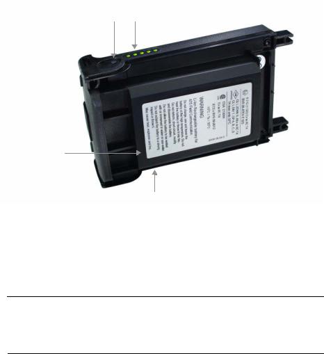
Checking the remaining charge
To view the remaining charge, press the Charge Indicator button on the lower left side of the battery. See Figure 2-1 for the location of this button. When you press and release the button, the lights above the button slowly illuminate to display the charge remaining. Each light represents 20 percent of the charge. The battery is fully charged when all of the lights are illuminated.
You can also check the remaining charge from the Settings menu on the Field Communicator Main Menu. See “Power” on page 25 for more information.
Figure 2-1. Li-Ion battery example
|
Charge Indicator button |
Lights illuminated by pressing the Charge |
|
Indicator button |
Li-Ion battery
Green power supply/charger connector (side)
Charging the battery
Prior to first portable use, fully charge the battery. The battery can be charged separately or while attached to the 475 Field Communicator. The 475 Field Communicator is fully operable while the battery is recharging, and a full charge takes 2-3 hours. An overcharge condition will not occur if the power supply/charger remains connected.
 CAUTION
You can remove and install the Li-Ion battery in a hazardous area environment. You cannot charge the battery in this environment because the power supply/charger is not IS-approved.
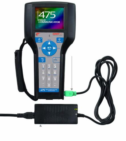
To charge the battery:
1.Plug the power supply/charger into a power outlet.
2.Plug the green power supply/charger connector into the green connector on the battery. The flat side of the power supply/charger connector should face the front of the 475 or the inside of the battery, if the battery is not attached to the 475. The battery is fully charged when the light on the power supply/charger is green.
Figure 2-2. Charging the battery connected to the 475 Field
Communicator
Power supply/charger connector
|
Power supply/charger |
Power supply/charger lights |
Power supply/charger lights
Three lights are on the power supply/charger to indicate the conditions below. Each light displays a different color.
Table 2-1. Power supply/charger lights
|
Color |
Condition |
|
Green |
The battery is fully charged. |
|
Flashing green |
The battery is nearly fully charged. |
|
Yellow |
The battery is charging. |
|
Flashing yellow |
The power supply/charger is not connected to |
|
the 475 Field Communicator. |
|
|
Flashing yellow and |
The remaining charge in the battery is very low. |
|
red |
|
|
Red |
Charging cannot occur. Contact Technical |
|
Support for more information. |
Maintaining the battery
To help maintain the performance and life of the Li-Ion battery, understand and follow the guidelines below:
•Recharge the battery frequently, preferably after each use or at night. Limit the number of full discharges, if possible.
•Frequent use at high temperatures can reduce performance.
•Use a dry location at or near room temperature when storing the battery for an extended time. Prolonged storage at higher temperatures can reduce performance.
•Ensure the remaining charge level is at or near mid-capacity when storing for an extended time. The remaining charge will slowly drain during storage. Periodically charge the battery to ensure the remaining charge does not drain to low levels.
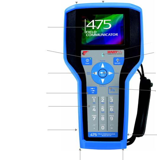
Figure 2-3. 475 Field Communicator shown with optional rubber boot
|
IrDA® interface |
HART and FOUNDATION fieldbus |
||
|
(top) |
communication terminals (top) |
||
Touch screen display
Power key and light
Strap attachment
 (side)
Navigation keys (four arrow keys)
Li-Ion battery (back) and
System Card (internal)
Tab key
Alphanumeric
keypad
Lights illuminated by pressing the Charge Indicator button (side)
Charge Indicator button  (side)
Strap attachment (side)
Bluetooth®
 light
light
 Backlight key
 Strap attachment (side)
Enter key
 Stylus (in the strap)
 Function key and light (for multiple-key combination functionality)
Green power supply/charger connector on the battery
(side)
Strap attachment (side)
Using the touch screen The touch screen and keypad let you select menu items and enter text. Use the provided stylus or the up and down arrow keys on the keypad to select a menu item. On the Settings and Field Communicator Main Menu, tap an icon or press Enter to open the selected icon. On other menus, double-tap the selected item on the screen or press the right arrow key on the keypad to open a menu item.
CAUTION
Contact the touch screen with blunt items only, preferably the stylus included with the 475 Field Communicator. See Figure 2-3 on page 15 for the location of the stylus. Sharp instruments, such as screwdrivers, can damage the touch screen. Repairing the touch screen requires replacement of the entire display assembly, which is possible only at an authorized service center.
|
Use the back arrow icon ( |
) on the window to return to the previous |
|
|
menu. Use the close icon ( |
) in the upper right corner of the window |
|
|
to end the application. |
||
|
If the touch screen seems inaccurate, you can recalibrate it. For more |
||
|
information, see “Touch Screen” on page 26. |
||
|
NOTE |
||
|
All instructions in this manual are written for the touch screen. |
||
|
Use the soft input panel (SIP) keyboard |
||
|
The SIP keyboard allows for alphanumeric input using the touch |
||
|
screen. The SIP keyboard detects when you need to enter characters |
||
|
and appears automatically as required. |
||
|
Using the keypad |
The following section describes the buttons on the 475 Field |
|
|
Communicator keypad. |
Bluetooth symbol (  )
)
The Bluetooth symbol on the keypad is illuminated by a blue light when
Bluetooth is enabled from the Listen for PC window. The 475 Field
Communicator must be licensed for Bluetooth to use this functionality.
Power key
The Power key is used to power on and off the 475 Field Communicator or to put it in standby. You can set the default option, stand by or shut down, from the Settings menu. See “Power Button” on page 26 for more information. The green light on the Power key flashes when you press and hold the Power key to turn on the 475 Field Communicator. The light is constant when the 475 is on, and it slowly blinks when the 475 is in standby.
If the Power key is pressed when there is unsent data or a device method is running, a warning message appears. Tap OK to have the 475 Field Communicator enter standby or shut down, or tap Cancel to return to the previous window.
The Power key is disabled when the 475 Field Communicator is in Listen for PC mode or when the ScratchPad application is open.
Arrow navigation keys
Four arrow navigation keys let you move through the menus and icons in the applications. Press the up and down arrow keys to select a menu item. On the Settings and Field Communicator Main Menu, tap an icon or press the Enter key to open the selected menu. On all other menus, use the right arrow key to open a menu item or the left arrow key to return to the previous menu.
The blue text near the keys indicates alternate functionality that can be enabled by pressing the Function key.
Enter key
The Enter key lets you open the selected (highlighted) button on a window or an icon on the Field Communicator Main Menu or Settings Menu. For example, if you push the Enter key when the Cancel button on a window is selected, you will close that window.
Tab key
The Tab key lets you move between selectable controls on a window. Pressing the Tab key selects the icons from left to right across all of the rows on the screen.
Alphanumeric keypad
The alphanumeric keypad lets you enter letters, digits, and other characters, such as punctuation marks. The 475 Field Communicator automatically determines which text options are available depending upon the input necessary for the particular field.
To enter text when in alphanumeric mode, press the desired keypad button in quick repetition to scroll through the options to display the appropriate letter or number. For example, to type the letter Z, press the 9 key quickly four times.
The blue text near the keys indicates alternate functionality that can be enabled by pressing the Function key. The alternate function on the alphanumeric 5 key (insert) will be activated in future releases of the 475 Field Communicator software.
|
18 |
Learning the basics |
|
Backlight key |
|
|
The Backlight key lets you adjust the intensity of the touch screen |
|
|
display. There are four different settings. The intensity impacts the |
|
|
charge in the battery. Expect a shorter charge life for higher intensities. |
|
|
See “Backlight” on page 24 for information on timers that can turn off |
|
|
the backlight after specified periods of inactivity. These timers can help |
|
|
conserve the battery power. |
|
|
Function (Fn) key |
|
|
The Function key lets you enable alternate functionality on select keys. |
|
|
The Function key does not apply for menus displaying icons.The blue |
|
|
text near the other keys on the keypad indicate the alternate |
|
|
functionality. When the Function key is enabled, the orange light in the |
|
|
left corner of the Function key appears and the FN button on the Soft |
|
|
Input Panel (SIP), if displayed, is highlighted. Press the Function key |
|
|
again to disable the functionality and turn off the light. |
|
|
Memory |
Types |
|
The 475 Field Communicator memory consists of three components: |
|
|
1.Internal Flash—32MB non-volatile RAM. The Internal Flash memory |
|
|
stores the operating system and system software. It also stores the |
|
|
following: |
|
|
• Up to 25 HART configurations |
|
|
• HART Event Captures |
|
|
• FOUNDATION fieldbus statistics |
|
|
• Text files saved from ScratchPad |
|
|
2.System Card—an internal 1 GB or higher Secure Digital Card with |
|
|
non-volatile flash memory. A copy of installable system software |
|
|
exists on every System Card. The System Card also contains all |
|
|
HART and FOUNDATION fieldbus device descriptions and can store |
|
|
up to 1,000 HART configurations, depending on the sizes of the files. |
|
|
3.RAM—32MB used only for program execution. |
|
|
Available memory space |
|
|
To view the available memory in your 475 Field Communicator, |
|
|
connect to the Field Communicator Easy Upgrade Utility or tap the |
|
|
Memory icon from the Settings menu. The Field Communicator Main |
|
|
Menu displays the Settings menu item. See “Memory” on page 27 for |
|
|
more information. |
|
|
Free memory on the System Card |
|
|
Over time, your System Card may become full and unable to store new |
|
|
files. To free memory on your System Card, use the Memory |
|
|
Management feature in the Field Communicator Easy Upgrade Utility. |
|
|
This lets you filter and select which device descriptions can be |
|
|
transferred onto your System Card. Device descriptions from selected |
|
|
manufacturers or protocols are omitted during an upgrade, allowing |
|
|
more space for other files. |
|
Learning the basics |
19 |
|
If the selected device descriptions are already on your 475, they are |
|
|
removed the next time you connect the 475 Field Communicator to the |
|
|
Easy Upgrade Utility. You are prompted before the files are removed. |
|
|
See the Easy Upgrade Utility Help for more information. |
|
|
Accessories |
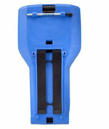
Rubber boot |
|
A rubber boot can be purchased to further protect your 475 Field |
|
|
Communicator. The boot has an additional stand on the back, cut outs |
|
|
for the straps, and holders for the stylus. An anti-static material is used |
|
|
to meet the applicable Intrinsic Safety requirements. |
|
|
Figure 2-4. Back of the 475 Field Communicator Rubber Boot |
Straps
Two straps are available with the 475 Field Communicator. The magnetic strap attaches to the top of the 475 Field Communicator and lets you hang it from a metal pipe. The strap attachment is located near the HART and fieldbus terminals on the top of the 475 Field Communicator.
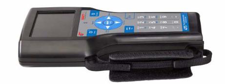
The side strap lets you attach a strap to the sides or back of the 475 Field Communicator, making it easy to carry. See Figure 2-5. The side strap also holds the stylus used with the touch screen.
Figure 2-5. Side Strap Example
ASSEMBLY
Installing the System Card and the battery
If you received a 475 Field Communicator with the System Card already installed, proceed to the » Starting up» section.
1.Place the 475 Field Communicator face down on a level, secure surface.
2.Remove the protective rubber boot, if attached.
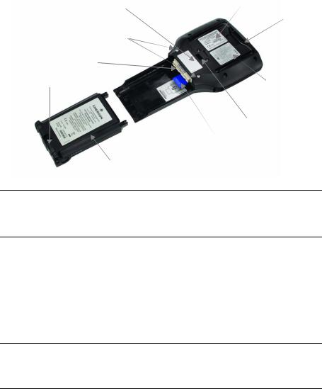
3.With the battery removed, slide the System Card (labeled System Card), with the metal card contacts facing up, into the System Card socket until it clicks. The System Card socket is spring-loaded. See Figure 2-6 for the location of the System Card socket.
The System Card is not locked into the System Card socket in the image below.
Figure 2-6. Back of the 475 Field Communicator
Bluetooth approval label
Battery retaining screws
Connector pins
Strap attachment
 Li-Ion battery
Main unit label
 Stand
Stand
 IS label (KL option)
Strap attachment
 System Card partially inserted into the System Card socket
CAUTION
The System Card must be supplied by the 475 Field Communicator manufacturer. Failure to comply will void the IS approval.
4.With the 475 Field Communicator still face down, ensure the tops of the two battery retaining screws are loose and slightly above the top of the 475.
5.Align the sides of the battery with the 475 and carefully slide it forward until it is secure.
6.Carefully hand tighten the two battery retaining screws to secure the battery. (Do not over tighten, 0.5Nm maximum torque load.)
CAUTION
The connector pins may be damaged if the 475 Field Communicator and battery are improperly aligned.
Removing the battery and the System Card
STARTING UP AND
SHUTTING DOWN
Starting up
The Field Communicator
Main Menu
To remove the battery and System Card:
1.Remove the rubber boot, if attached.
2.Place the 475 Field Communicator face down on a level, secure surface.
3.Loosen the battery retaining screws until the top of each screw is slightly above the top of the 475 Field Communicator.
4.Slide the battery off the 475 Field Communicator. Do not pull up the battery because this could damage the connector pins.
5.Push the System Card into the System Card socket until it clicks to release it. The System Card socket is spring-loaded.
6.Grasp the System Card with your fingers and slide it straight out of the 475 Field Communicator.
Prior to using the 475 Field Communicator without the power supply/charger, fully charge the battery. See “Charging the battery” on page 12 for more information.
Before operating the 475 Field Communicator, ensure:
•The 475 Field Communicator is not damaged.
•The battery is fully seated.
•All screws are sufficiently tightened.
•The communication terminal recess is free of dirt and debris.
Press and hold the Power key on the keypad until the green light on that key flashes (approximately two seconds). See Figure 2-3 on page 15 for the location of the Power key.
During startup, the 475 Field Communicator automatically checks for any system software upgrades available on the internal System Card. You are notified if an upgrade is on the System Card and ready to be installed. The Field Communicator Main Menu appears.
The Field Communicator Main Menu is the first menu that appears after you start the 475 Field Communicator. This menu lets you run the HART and the Fieldbus Applications, view the Settings menu, communicate with a PC, and launch ScratchPad or ValveLink™ Mobile. See Section 3 “HART Functionality” and Section 4 “Fieldbus Functionality” for more information on these applications.
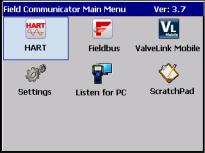
Figure 2-7. Field Communicator Main Menu
|
Entering standby |
You can put the 475 Field Communicator into standby to save power or |
|
to reduce the boot-up time if you are using the 475 Field |
|
|
Communicator intermittently. Standby turns off the touch screen and |
|
|
areas within the 475 Field Communicator. |
|
|
You can put the 475 Field Communicator in standby when the HART |
|
|
Application or the Fieldbus Application is running. If you are working |
|
|
online with a device when standby is entered, the application main |
|
|
menu is displayed when the 475 Field Communicator returns from |
|
|
standby. Otherwise, the 475 Field Communicator displays the last |
|
|
open window. |
|
|
To enter standby, press the Power key. From the Power Switch dialog |
|
|
box, tap Stand by and tap OK or press the Enter key. Tap Cancel to |
|
|
close the dialog box and return to the application. You can set the |
|
|
default option on the Power Switch dialog box. See “Power Button” on |
|
|
page 26 for more information.The green light on the Power key slowly |
|
|
flashes when the 475 Field Communicator is in standby. To leave |
|
|
standby, press the Power key. |
|
|
The 475 Field Communicator also enters standby if the standby timer |
|
|
has expired. See “Power” on page 25 for more information. |
|
|
Shutting down |
To shut down the 475 Field Communicator, press the Power key. From |
|
the Power Switch dialog box, tap Shut down and tap OK or press the |
|
|
Enter key. Tap Cancel to close the dialog box and return to the |
|
|
application. You can set the default option on the Power Switch dialog |
|
|
box. See “Power Button” on page 26 for more information. |
|
|
The 475 Field Communicator shuts down if the auto-off timer has |
|
|
expired. See “Power” on page 25 for more information. |
|
|
You can also shut down the 475 Field Communicator by |
|
|
simultaneously pressing the Backlight key and the Function key until |
|
|
the display turns off. The shut down is accomplished in the hardware |
|
|
(similar to removing the power to a PC using a switch). This is not the |
|
|
recommended way of shutting off the 475 Field Communicator. Use |
|
|
this method to shut down and reset the 475 Field Communicator if the |
|
|
screen appears to lock up and does not respond when you use the |
|
|
touch screen or keypad. |

SETTINGS |
You can view and modify the options below for the 475 Field |
|
Communicator from the Settings option on the Field Communicator |
|
|
Main Menu. |
|
|
To return to the Field Communicator Main Menu, tap the Back button |
|
|
on the screen. Tap the MORE button to view additional items on the |
|
|
Settings menu. |
|
|
About |
The About setting lets you view the software revisions in your 475 Field |
|
Communicator. If you need to call Technical Support personnel, have |
|
|
the system software version, Communication and Diagnostic Circuitry |
|
|
(CDC) version, and the operating system version available. |
|
|
Tapping RE-IMAGE re-installs the operating system, system software, |
|
|
and applications on your 475 Field Communicator. The power |
|
|
supply/charger must be connected when the RE-IMAGE operation is |
|
|
performed. During the operation, the standby and auto-off timers are |
|
|
disabled. This operation should only be performed under the direction |
|
|
of Technical Support personnel. |
|
|
Tapping RE-FLASH re-installs the firmware and software from the |
|
|
System Card. The power supply/charger must be connected when the |
|
|
RE-FLASH operation is performed. During the operation, the standby |
|
|
and auto-off timers are disabled. This operation should only be |
|
|
performed under the direction of Technical Support personnel. |
|
|
Tap OK to return to the Settings menu. |
|
|
Backlight |
The Backlight setting lets you adjust the backlight intensity of the |
|
screen. To adjust the backlight, drag the slider left to right. |
|
|
The Backlight setting also lets you set timers to automatically turn off |
|
|
the backlight after a specified period of inactivity to save battery power. |
|
|
To enable a timer, tap a drop-down list and select the appropriate time |
|
|
interval. The external power timer applies when the power |
|
|
supply/charger is connected to the 475 Field Communicator |
|
|
After you select the appropriate backlight settings, tap OK to retain this |
|
|
setting for this session only, SET DEFAULT to retain this setting upon |
|
|
startup, or CANCEL to exit without changes. |
|
|
Clock |
The Clock setting lets you set the date, time, and time zone on the 475 |
|
Field Communicator. Configure the date by using the drop-down list. |
|
|
To configure the time, select the appropriate time field and use the |
|
|
arrows to scroll through values until you find the correct time. Select |
|
|
the drop-down list to select a time zone. Tap OK to save the changes |
|
|
and to close the window, or CANCEL to exit without changes. |
The Contrast setting lets you adjust the lightest and darkest areas on the window. This option applies to only the 375 Field Communicator.
NOTE
Temperature can affect contrast.
The Licenses setting lets you view the enabled and available licenses for the 475 Field Communicator. A checkmark indicates the license is enabled. Unlicensed features cannot be accessed. The following licenses and information are displayed:
•HART — enables your 475 to run the HART Application to communicate with HART devices.
•Graphics — enables your 475 Field Communicator to display device information as images, charts, and graphs.
•Easy Upgrade — enables you to upgrade your 475 Field Communicator with the latest system software and device descriptions at your site, without having to send it to a service center.
•Exp Date — displays the expiration date of the Easy Upgrade license. The date is listed as year-month-day. N/A appears if the 475 is not licensed for Easy Upgrade.
•Bluetooth — enables your 475 Field Communicator to communicate with supported PC applications, such as the Easy Upgrade Utility, using Bluetooth.
•FOUNDATION fieldbus — enables the 475 Field Communicator to run the Fieldbus Application to communicate with fieldbus devices.
•Device Config Management — enables you to save HART device or user configurations to the System Card and to print and store them using the Easy Upgrade Utility.
The License window also displays the Unit Name and System Card Serial Number (SN) of the 475 Field Communicator. See the Easy Upgrade Utility Help for more details on assigning a Unit Name. Tap OK to return to the Settings menu.
The Power setting lets you specify power management options when the 475 Field Communicator is on battery power. The standby timer puts the 475 Field Communicator in standby and the auto-off timer shuts down the 475 Field Communicator after the specified values of inactivity. To specify values for the standby or auto-off timer, select the time intervals from the drop-down lists. If set to short intervals, these timers will save battery power.
The Maximize Power Savings option conserves additional battery power by letting the 475 Field Communicator enter standby or shut down when communicating with a device. To enable Maximize Power Savings, tap the checkbox. If this option is disabled, the 475 Field Communicator will not enter standby or shut down when communicating with a device.

After you select the appropriate power management settings, tap OK to apply the settings for this session only, SET DEFAULT to retain the settings upon startup, or CANCEL to exit without changes.
 The Power Button setting lets you set the default option for the Power Power Button Switch dialog. The Power Switch dialog appears when you press the
Power key. This option does not let the Field Communicator automatically shut down or enter stand by when you press the Power key. You still need to tap OK.
From the Power Button screen, select the Stand by or Shut down option and then tap OK to apply the settings for this session only, SET DEFAULT to retain the settings upon startup, or CANCEL to exit without changes.
 The Retrain Battery setting lets you fully discharge the battery so it can Retrain Battery be charged to its full capacity. Perform this operation if you notice a
significant decrease in charge life or performance.
CAUTION
It should not be necessary to perform this operation on a regular basis.
Doing so may damage the Li-Ion battery.
Ensure the power supply/charger is not connected when this operation is performed. During the operation, the backlight is set to its brightest setting to quickly discharge the battery. The backlight, standby, and auto-off timers are disabled. If you tap CANCEL, the battery stops discharging and the backlight, standby, and auto-off timers are re-enabled. The backlight setting is also restored.
After the battery is fully discharged, make sure it is fully recharged before using it without the power supply/charger. You can use the 475 Field Communicator while the battery is recharging.
To retrain the battery:
1.Disconnect the power supply/charger, if it is connected to the 475 Field Communicator.
2.Tap Retrain Battery from the Settings menu.
3.Wait until the 475 Field Communicator shuts down. It may take up to several hours to discharge the battery, depending on the charge remaining when the operation began.
Connect the power supply/charger to the 475 Field Communicator and fully charge the battery.
 The Touch Screen setting lets you calibrate the touch screen with the Touch Screen display. Tap the center of the cross hairs firmly and accurately at each
location on the window. The target continues to move until the touch screen is aligned. Touch screen alignment is retained upon start up.
The Event Capture setting lets you create an Event Capture file (.rec), Event Capture which is a log of communication, input, and output that occurs between the 475 Field Communicator and a device (HART only). When working
with Technical Support personnel, you may be asked to create an Event Capture file to help troubleshoot issues that cannot be easily isolated or resolved. The Event Capture file can then be transferred to your PC using the Field Communicator Easy Upgrade Utility and sent to Technical Support personnel for review.
Tap the option to activate the Event Capture feature. The option is black when selected. To delete an existing Event Capture, tap
DELETE EVENT FILE.
NOTE
While Event Capture is enabled, device status and warning messages do not appear.
To create and send an Event Capture file:
1.Tap Settings from the Field Communicator Main Menu.
2.Tap MORE and then tap Event Capture.
3.Tap Turn on HART event capture from the Event Capture window and tap OK.
4.Tap HART from the Field Communicator Main Menu.
5.Enter a file name for the Event Capture file and tap OK. The file is saved to a default location.
6.Perform the requested operations to capture the data.
7.Use the Field Communicator Easy Upgrade Utility to transfer the file from your 475 Field Communicator to your PC. See the Easy Upgrade Utility Help for more information.
 The Memory setting lets you view available free space in the System Memory Card, Internal Flash, or RAM. To select the Memory icon, tap MORE
on the Settings screen. If you have less than 10 percent of memory free, the value is highlighted yellow.
|
28 |
Learning the basics |
|
CONNECTING TO A |
Use the provided lead set and the HART or Fieldbus (if licensed) |
|
DEVICE |
Applications to connect and communicate with a device. The |
|
appropriate device description is also required. If the 475 Field |
|
|
Communicator does not have the HART device description, the device |
|
|
can be displayed in forward compatibility mode. This mode uses a |
|
|
generic device description and does not display all device functionality. |
|
|
Three terminals for the lead set are on the top of the 475 Field |
|
|
Communicator. Each red terminal is a positive connection for its |
|
|
protocol, while the black terminal is a common terminal shared by both |
|
|
protocols. An access door ensures only one pair of terminals is |
|
|
exposed at any one time. Several markings indicate which pair of |
|
|
terminals is for which protocol. |
|
|
See «Section 3 HART functionality» and «Section 4 Fieldbus |
|
|
functionality» for wiring diagrams and more information. Appendix B |
|
|
displays diagrams for Intrinsically Safe installations. |
|
PC APPLICATIONS |
Connect your 475 Field Communicator to a supported PC application, |
|
such as AMS Suite: Intelligent Device Manager or the Field |
|
|
Communicator Easy Upgrade Utility, to download new system |
|
|
software, device descriptions, and licenses. You can also transfer |
|
|
HART configuration files, Event Capture files, and ScratchPad (.txt) |
|
|
files to a PC. |
|
|
AMS Device Manager |
The 475 Field Communicator can connect to AMS Device Manager |
|
(version 6.2 or higher), letting you create, open, edit, or compare |
|
|
HART device or user configuration files. You may need to connect |
|
|
using IrDA if Bluetooth is not supported in your version. You can also |
|
|
transfer configurations between AMS Device Manager and a storage |
|
|
location in the 475 Field Communicator. Check the AMS Device |
|
|
Manager Books Online for more information. |
|
|
Field Communicator Easy |
The 475 Field Communicator can connect to the Field Communicator |
|
Upgrade Utility |
Easy Upgrade Utility that is available on the Resource CD or DVD. See |
|
the readme file for installation and system requirements. You can |
|
|
access this file from www.fieldcommunicator.com or the Resource CD |
|
|
or DVD. |
Connecting the 475 Field Communicator or System Card
The Easy Upgrade Utility lets you do the following:
•Download new system software and device descriptions to upgrade your 475 Field Communicator at your site.
•Enable new functionality and applications by purchasing and downloading new application licenses using the Online Licensing feature.
•Upload Event Capture and ScratchPad files to your PC.
•Upload, download, and print HART device or user configurations (.hcf files). Uploading configurations to the Easy Upgrade Utility lets you back up these files.
•Manage the memory in your System Card by specifying which device descriptions can be downloaded to your System Card. Limiting the number of device descriptions will free memory on your System Card.
•Assign a Unit Name to a 475 Field Communicator to uniquely identify it, which is useful when connecting to a 475 Field Communicator using Bluetooth.
See the Easy Upgrade Utility Help for more information on these features.
You can use three connection types to connect a 475 Field Communicator to the Easy Upgrade Utility: IrDA, Bluetooth (if licensed), or a supported card reader. The 475 Field Communicator must be in Listen for PC mode to communicate through IrDA or Bluetooth. See the AMS Device Manager Books Online for information on supported connection types.
Certain connection types are required to transfer files or information between the Field Communicator Easy Upgrade Utility and a 475 Field Communicator. See Table 2-2.

|
30 |
Learning the basics |
|
|
Table 2-2. Required connection types to transfer files using the Easy |
||
|
Upgrade Utility |
||
|
File to Transfer |
Required Connection Type |
|
|
Device Descriptions* |
IrDA, Bluetooth, or a Card Reader |
|
|
Event Capture Files |
IrDA or Bluetooth |
|
|
HART Device or User |
IrDA, Bluetooth, or a Card Reader |
|
|
Configuration Files |
||
|
Licenses |
IrDA or Bluetooth |
|
|
ScratchPad (.txt) Files |
IrDA or Bluetooth |
|
|
System Software* |
IrDA, Bluetooth, or a Card Reader |
|
|
Unit Name |
IrDA or Bluetooth |
*Some upgrades may require a card reader.
 Listen for PC
The Listen for PC option lets you select IrDA or Bluetooth as the connection type to communicate with a PC. To enter Listen for PC mode, tap the Listen for PC icon from the Field Communicator Main Menu. IrDA is initially set as the default connection type and is automatically enabled when you open Listen for PC.
You can change the connection type at any time by tapping the Change Connection Type button and then selecting an option. Tap OK to use the selected connection type for only the current session. The default connection type is used the next time you open Listen for PC. Tap Save as Default to always use the selected connection type when Listen for PC is opened.
After you select the connection type, the 475 Field Communicator waits for a connection from the PC. When the 475 is connected, a message appears and the PC name is listed in the Connected PC field on the Listen for PC window.
NOTE
The Power key, standby timer, and auto-off timer are disabled when the 475 Field Communicator is in Listen for PC mode.
Bluetooth
The Bluetooth interface (if licensed) lets your 475 Field Communicator connect to the Field Communicator Easy Upgrade Utility version 3.0 or higher to transfer device descriptions, system software, configurations, Event Captures, application licenses, and ScratchPad (.txt) files.
Check your AMS Device Manager documentation to see if Bluetooth is supported.

NOTE
The 475 Field Communicator does not communicate with HART or fieldbus devices using Bluetooth.
To use Bluetooth, you need the following:
•475 Field Communicator with a Bluetooth license. To see if your 475 is licensed for Bluetooth, tap the Settings icon from the Field Communicator Main Menu. Then tap Licenses. A checkmark next to Bluetooth indicates it is licensed.
•An approved Bluetooth adapter attached to your PC that uses the Windows Bluetooth software and drivers. See the Easy Upgrade Utility Help and readme file for more information. You can access the readme file from www.fieldcommunicator.com, the Resource CD or DVD, or the Field Communicator Easy Upgrade Utility menu in the Windows Start menu (if the Easy Upgrade Utility has been installed.)
If Bluetooth is not set as the default connection type, you need to enable it on the Listen for PC window. To enable Bluetooth communication:
1.Tap Listen for PC from the Field Communicator Main Menu.
2.Tap Change Connection Type.
3.Tap Bluetooth and then tap OK. You can tap Save as Default to always use Bluetooth as the connection type.
The Bluetooth symbol on the keypad is illuminated by a blue light ( ) and a “Waiting for connection” message appears when Bluetooth is enabled. See Figure 2-3 for the location of this light.
The maximum recommended distance between the 475 Field Communicator and PC is 30 feet (10 meters). See the Help in the Easy Upgrade Utility or AMS Device Manager for more information about connecting using Bluetooth.
IrDA
The 475 Field Communicator can communicate with the Field Communicator Easy Upgrade Utility and AMS Device Manager using infrared (IrDA) technology. IrDA is a PC interface supported for the transfer of device descriptions, software updates, configurations, Event Captures, application licenses, and ScratchPad files. See Figure 2-3 on page 15 for the location of the IrDA interface on the 475 Field Communicator. All 475 Field Communicators can use IrDA.
IrDA communication can either be built into the PC, such as a laptop, or provided through an adapter such as a USB to IrDA adapter. Refer to your IrDA manual for installation and operating instructions. The maximum recommended distance between the IrDA and PC is 18 inches.
If you previously set Bluetooth as the default connection type, you need to enable IrDA.

To enable IrDA communication:
1.Tap Listen for PC from the Field Communicator Main Menu.
2.Tap Change Connection Type.
3.Tap IrDA and then tap OK.You can tap Save as Default to always use IrDA as the connection type.
A “Waiting for connection” message appears when IrDA is enabled.
See AMS Device Manager Books Online or the Easy Upgrade Utility
Help for instructions to connect to those applications using IrDA.
Card reader
The 475 Field Communicator System Card can also communicate with the Easy Upgrade Utility using a supported Secure Digital card reader. See the readme file for the supported card readers. You can access this file from www.fieldcommunicator.com, the Resource CD or DVD, or the Field Communicator Easy Upgrade Utility menu in the Windows Start menu (if the Easy Upgrade Utility has been installed.)
CAUTION
Using Windows Explorer and a card reader to manually transfer or copy files between the System Card and a PC can corrupt the System Card. This operation should only be performed under the direction of Technical Support personnel.
The card reader provides faster upload and download speeds than an IrDA adapter; however, it cannot transfer application licenses, Event Capture files, or ScratchPad files.
To access the System Card, you need to remove the battery from the 475 Field Communicator. See “Removing the battery and the System Card” on page 22 for more information.
See the Easy Upgrade Utility Help for instructions to connect a System Card and card reader.

Upgrading the 475 Field
Communicator
Adding functionality by enabling licenses
The Field Communicator Easy Upgrade Utility on the Resource CD or DVD lets you download new system software and device descriptions to upgrade your 475 Field Communicator at your site. To download new system software and device descriptions, your 475 Field Communicator must be licensed for Easy Upgrade.
You can also send your Field Communicator to a Service Center to be upgraded. For more information, contact your sales representative.
CAUTION
New system software and device descriptions must be downloaded and transferred to the 475 Field Communicator using the Easy Upgrade Utility. Manually copying files to the System Card using Windows Explorer will corrupt the System Card.
Downloading new system software and device descriptions
Download the latest system software and device descriptions from the Internet by using the Update PC functionality in the Easy Upgrade Utility (version 3.0 or higher). An Internet connection is required to download the new files. If your site does not have Internet access, a Resource CD or DVD can provide the latest updates.
Transferring the system software and device descriptions
Use the Easy Upgrade Utility to transfer all the files to a connected 475 Field Communicator. You can use IrDA, Bluetooth, or a card reader to connect to the Easy Upgrade Utility and transfer the upgrades. Large or critical upgrades may require a card reader. See the Easy Upgrade Utility Help for information on connecting and upgrading a 475 Field Communicator.
The Easy Upgrade Utility also lets you transfer a specific system software or device description version. Connect a 475 Field Communicator or System Card and click the More Options button on the Upgrade window to access the System Software and DDs tabs.
The HART Application, Device Configuration Management, and Graphics are licensed in all 475 Field Communicators, but other functionality requires a license. Renew or add licenses anytime at your site by using the Online Licensing feature in the Field Communicator Easy Upgrade Utility. Only the Easy Upgrade license needs to be renewed.

Viewing current licenses
To view the current licenses and the Easy Upgrade expiration date in your 475 Field Communicator, tap the Settings icon from the Field Communicator Main Menu. Then tap the Licenses icon.
The Easy Upgrade Utility can also display all licensing information from the Licensing & Registration window or Upgrade window. A 475 Field Communicator must be connected to view licensing information from the Upgrade window.
Purchasing and downloading new licenses
You can select and enable new licenses for a 475 Field Communicator from your site. There are four basic steps to obtain new licenses:
1.Register your 475 Field Communicator by connecting it to the Easy Upgrade Utility and logging in to the Licensing & Registration window.
2.Select the licenses to purchase and note the appropriate part numbers. You can select licenses for multiple Field Communicators at one time.
3.Submit a purchase order to your sales representative.You are notified when your order has been processed and the licenses are available for download.
4.Connect the 475 Field Communicator to the Easy Upgrade Utility, and use the Licensing & Registration window to enable the purchased licenses.
See the Easy Upgrade Utility Help for more information on selecting and enabling licenses.
You can send your 475 Field Communicator to a service center to have a technician enable licenses for you. Contact your sales representative for more information.
 ScratchPad is a text editor that you can use to create, open, edit, and SCRATCHPAD save simple text (.txt) documents. ScratchPad supports very basic
 ScratchPad is a text editor that you can use to create, open, edit, and
 formatting. From the Field Communicator Main Menu, tap the ScratchPad icon to run the application. You can also launch ScratchPad from within the HART or Fieldbus Application by tapping the ScratchPad ( ) icon in the upper right corner of the window.
You can transfer text files between a PC and the 475 Field Communicator using the Field Communicator Easy Upgrade Utility.
NOTE
The Power key, standby timer, and auto-off timer are disabled when the ScratchPad application is open.

Creating a new document From the Main Page in ScratchPad, tap NEW. An empty text window and SIP keyboard appears. See Figure 2-8. You are now ready to enter text into your new document.
A new document can also be created within ScratchPad by tapping the New (  ) icon in the toolbar or by selecting File | New from the menu.
Figure 2-8. ScratchPad displaying the SIP keyboard
Opening an existing document
1.From the Main Page in ScratchPad, select the desired file located under File Name.
2.Tap OPEN. A text window and the SIP keyboard appears. You are now ready to edit your document.
You can also open a document by selecting File | Open from the menu bar or by tapping the Open ( ) icon in the toolbar.
Entering text
Using the stylus, tap the desired letters from the SIP keyboard. Using the keypad, press the desired keypad button in quick repetitions to display the appropriate letter or number.
Selecting text
Drag the stylus over the desired text to highlight or to select all of the text in the document tap Edit | Select All.
Cutting text
1.Select the text to be cut.
2.Tap Edit | Cut.
You can also cut text by selecting text and tapping the Cut ( ) icon in the toolbar.
Copying text
1.Select the text to be copied.
2.Tap Edit | Copy.
You can also copy text by selecting text and tapping the Copy ( ) icon in the toolbar.

Pasting text
1.Copy the text to be pasted.
2.Tap a location on the screen. This is where the text will be pasted.
3.Tap Edit | Paste.
You can also paste text by copying the text and tapping the Paste ( ) icon in the toolbar.
Saving a document
1.In your document, tap File | Save.
2.Type the file name in the dialog box if your document is new.
3.Tap OK.
You can also save a document by tapping the Save ( ) icon in the toolbar.
Saving a copy
To save a copy of the current document under another name:
1.In your document, tap File | Save As…
2.Type the copy file name in the dialog box.
3.Tap OK.
Deleting a document
There are three options for deleting a ScratchPad document:
Option 1
1.From the Main Page in ScratchPad, select the file to be deleted.
2.Tap DELETE.
3.A warning appears telling you that the selected file will be permanently deleted. If you are sure you want to delete this file, tap
Yes.
Option 2
1.To delete from your document, tap File | Delete.
2.From the Delete File Page, tap the desired file to be deleted.
3.Tap OK.
4.A warning appears telling you that the selected file will be permanently deleted. If you are sure you want to delete this file, tap
Yes.
5.Tap EXIT when you are finished deleting files.
Option 3
Delete the .txt file using the Easy Upgrade Utility. See the Easy
Upgrade Utility Help for more information on deleting a User Data file.
Exiting
1.In your document, tap File | Exit.
2.Tap the EXIT button from the Main Page.

|
Learning the basics |
37 |
||
VALVELINK MOBILE |
ValveLink Mobile lets you configure, calibrate, and troubleshoot Fisher |
||
|
digital valve controllers (DVC) through an easy-to-use, graphical |
|||
|
interface.To open ValveLink Mobile, tap the ValveLink Mobile icon |
|||
|
from the Field Communicator Main Menu. The Field Communicator |
|||
|
must have a 1 GB or larger System Card and a valid Easy Upgrade |
|||
|
license to open ValveLink Mobile. |
|||
|
Use the leadset to connect to the DVC and run the desired diagnostics |
|||
|
or operations. See the ValveLink Mobile documentation at |
|||
|
www.fieldcommunicator.com for more information about the |
|||
|
functionality. |
|||
|
Upgrades to ValveLink Mobile are included with the Field |
|||
|
Communicator system software updates. Use the Easy Upgrade Utility |
|||
|
to download updates from the Internet to your PC and then transfer |
|||
|
them to your Field Communicator. A card reader may be required. |
|||
|
NOTE |
|||
|
The standby timer and auto-off timer are disabled when ValveLink |
|||
|
Mobile is open. |
|||
MAINTENANCE |
|||
|
Any maintenance, repair, or replacement of components not listed |
|||
|
below must be performed by specially trained personnel at authorized |
|||
|
service centers. You can perform common maintenance procedures |
|||
|
on the 475 Field Communicator, as described below: |
|||
|
• |
Cleaning the exterior. Use only a dry, lint-free towel or dampen the |
||
|
towel with a mild soap and water solution. |
|||
|
• |
Charging, removing, and replacing the battery. |
||
|
• |
Removing and replacing the System Card. |
||
|
• |
Removing and replacing the stand. |
||
|
• |
Ensuring that all exterior screws are sufficiently tightened. |
||
|
• |
Ensuring that the communication terminal recess is free of dirt and |
||
|
debris (does not require disassembly). |
|||
|
Running a self test |
There is no need, nor is it possible, to perform a manual self test with |
||
|
the 475 Field Communicator. Testing features are done automatically. |
|||
|
A warning message appears if a fault condition is found during these |
|||
|
tests. |
|||
|
Calibrating |
It is not necessary or possible to calibrate the 475 Field Communicator. |
||
|
The 475 Field Communicator is a communication interface that |
|||
|
communicates digitally with HART and FOUNDATION fieldbus devices. |
Voltage measurements made by the 475 Field Communicator are for use in detection of power or noise on a network, and are for reference purposes only. NIST standards are not applicable to the 475 Field Communicator.

|
475 FIELD COMMUNICATOR |
|||
|
SECTION 3 |
HART FUNCTIONALITY |
||
OVERVIEW |
This section provides instruction on basic HART functionality in the 475 |
||
|
Field Communicator. It is based on the operation of the HART |
|||
|
Application version 6.1. |
|||
SAFETY MESSAGES |
Procedures and instructions in this section may require special |
||
|
precautions to ensure the safety of the personnel performing the |
|||
|
operation. Information that raises potential safety issues is indicated by |
|||
|
a warning symbol ( ). Refer to the safety messages before |
|||
|
performing an operation preceded by this symbol. Other warning |
|||
|
messages can be found in the “Troubleshooting” section of this |
|||
|
manual. |
|||
|
WARNING |
|||
|
If you choose to ignore all field device status messages, every |
|||
|
message, regardless of severity, is ignored until the specified |
|||
|
number of messages is reached. See “Ignoring status messages” |
|||
|
on page 55 for more information. |
|||
|
WARNING |
|||
|
Voltage measurements are for reference purposes only. Do not |
|||
|
make critical process control decisions based on these |
|||
|
measurements. |
|||
www.fieldcommunicator.com

BASIC FEATURES AND FUNCTIONS
HART Application functionality
Using a fast key sequence
STARTING THE HART APPLICATION
The HART Application lets you communicate with and configure HART devices that are connected to the 475 Field Communicator. You can also create and edit configurations and run diagnostics.
A fast key sequence is a sequence of numerical button presses, corresponding to the menu options that lead you to a given task. See your device documentation for fast key sequence options.
To start the HART Application:
1.Press and hold the Power key until the green light on that key blinks to turn on the 475 Field Communicator.
2.Tap from the Field Communicator Main Menu. If a live HART device is connected to the 475 Field Communicator, the HART Application Online menu appears automatically. If a device is not connected, the HART Application main menu appears after a few seconds. See Figure 3-1.
To return to the Field Communicator Main Menu, press the left arrow key on the keypad or tap the back arrow on the window. Select Yes when prompted if you want to exit the HART Application.
From the HART Application main menu, you can choose Offline, Online, Utility, or HART Diagnostics functions. The rest of this section guides you through the HART Application menus and functions.
Figure 3-1. HART Application Main Menu
 Loading…
1 User s ManualRev K May 2015 User s Manual475 Field Communicator Read this User s manual before working with the 475 field communicator . For personal and system safety, and for optimum product performance, thoroughly understand the contents before using or servicing this product. For equipment service needs, contact the nearest product Field Field Communicator Emerson Process Management. 2015. All rights Emerson logo is a trademark and service mark of Emerson Electric , DeltaV, and ValveLink are marks of one of the Emerson group of is a registered trademark of Microsoft Corporation in the United States and other is a registered trademark of the Infrared Data is a registered trademark of the Bluetooth SIG, is a trademark of the Fieldbus Foundation of Austin, Texas, and WirelessHART are registered trademarks of the HART Communication Foundation of Austin, Texas, is a registered trademark of Hitachi America, Ltd.
2 All other marks are property of their respective Field COMMUNICATORTABLE OF CONTENTSSECTION 1 IntroductionUsing this manual .. 7 SECTION 2 Learning the basicsOverview .. 9 Safety messages .. 9475 Field Communicator overview .. 10 Device interoperability.. 10 Working in a hazardous area .. 11 Battery and power supply/charger .. 11 Using the touch screen .. 16 Using the keypad .. 16 Memory .. 18 Accessories.. 19 Assembly.. 21 Installing the System Card and the battery .. 21 Removing the battery and the System Card .. 22 Starting up and shutting down .. 22 Starting up.. 22 The Field Communicator Main Menu .. 22 Entering standby .. 23 Shutting down .. 23 Settings .. 24 About.. 24 Backlight .. 24 Clock .. 24 Contrast .. 25 Licenses .. 25 Power .. 25 Power Button .. 26 Retrain Battery.
3 26 Touch Screen .. 26 Event Capture .. 27 Memory .. 27 Connecting to a device .. 28PC applications.. 28 AMS Device Manager .. 28 Field Communicator Easy Upgrade Utility .. 28 Connecting the 475 field communicator or System Card29 Upgrading the 475 field communicator .. 33 Table of Contents4 Adding functionality by enabling licenses .. 33 ScratchPad .. 34 Creating a new document .. 35 Opening an existing document .. 35 ValveLink Mobile .. 37 Maintenance .. 37 Running a self test .. 37 Calibrating .. 37 SECTION 3 HART functionalityOverview .. 39 Safety messages .. 39 Basic features and functions .. 40 HART Application functionality .. 40 Using a fast key sequence .. 40 Starting the HART Application .. 40 Working with offline configurations .. 41 Creating a new configuration.
4 41 Opening a saved configuration .. 42 Transferring configurations to a PC application .. 44 Working online with HART devices .. 45 Connecting to a HART device.. 45 Displaying the connected HART devices .. 48 The HART icon .. 49 Saving a device configuration .. 49 Displaying Device Setup options .. 50 Displaying Graphics .. 51 Configuring the HART Application .. 52 Using hot keys .. 52 Changing the HART polling options .. 53 Ignoring status messages .. 55 Displaying the HART short tag or long tag in a menu title 55 Storage Cleanup .. 55 Viewing available device descriptions.. 56 Simulating an online connection to a HART device .. 56 Running HART diagnostics .. 57DC voltage measurement (HART terminals) .. 57 Disconnecting from a HART device .. 57 SECTION 4 Fieldbus functionalityOverview.
5 59 Safety messages .. 59 Basic features and functions .. 60 Fieldbus Application functionality .. 60 Link Active Scheduler (LAS) .. 60 LAS hierarchy .. 60 Table of Contents5 Starting the Fieldbus Application .. 61 Working online with fieldbus devices .. 61 Connecting to a fieldbus device .. 62 Displaying the connected fieldbus devices .. 65 Displaying the online device .. 66 Block modes .. 66 Device blocks .. 69 Displaying Graphics .. 75 Configuring the Fieldbus Application .. 75 Changing the fieldbus polling addresses .. 75 Changing the Slot Time .. 76 Viewing available device descriptions.. 76 Running fieldbus diagnostics .. 77DC voltage measurement .. 77 Noise level measurement .. 77 Signal level measurement.. 77 Disconnecting from a fieldbus device .. 78 SECTION 5 TroubleshootingOverview.
6 79 Troubleshooting suggestions .. 79 Error and status messages .. 84 Information for Technical Support .. 90 APPENDIX A Reference dataProcessor and memory specifications.. 91 Microprocessor .. 91 Memory .. 91 Physical specifications .. 91 Weight.. 91 Display .. 91 Keypad .. 91 Usage specifications .. 92 Temperature limits .. 92 Storage with batteries .. 92 Storage without batteries .. 92 Enclosure rating .. 92 Shock .. 92 General guidelines .. 92 Connection specifications.. 92 HART and fieldbus communication terminals .. 92 Connection types .. 92 Battery specifications .. 93 Battery type.. 93 Connection .. 93 Charge .. 93 Table of Contents6 Lights .. 93 Operating time .. 93 Storage .. 93 Power supply/charger specifications .. 94 Connection .. 94 Lights .. 94 Voltage.
7 94 Technical data.. 94 Order information .. 95 Spare parts list .. 97 APPENDIX B Product certificationsOverview .. 99 Approved Manufacturing Locations .. 99 FCC .. 99IC .. 99 Telecommunications Regulatory Authority .. 100 European Directive Information — CE Compliance .. 100R&TTE (1999/5/EC) .. 100 Electro Magnetic Compatibility (2004/108/EC) .. 100 Low Voltage (2006/95/EC) .. 100 ATEX Directive (94/9/EC) (KL option only) .. 100 Hazardous Locations Certifications (KL option only). 100 European Certifications.. 100 International Certification .. 101 North American Certifications .. 101 Power Supply/Charger Certification .. 102 Declaration of Conformity/Approvals .. 102 Label Drawings .. 102 Approval Drawings.. 106 APPENDIX C Graphics informationOverview .. 111 Screen layout .. 111 Buttons.
8 112 Graphics options .. 112 Images .. 112 Charts .. 113 Graphs .. 116 Glossary .. G-117 Index .. Field COMMUNICATORSECTION 1 INTRODUCTIONUSING THIS MANUALThe sections in this manual provide the following information on the 475 field communicator . Section 2: Learning the basics contains information on assembly, components, starting, entering standby, shutting down, settings, supported PC applications, and maintaining the 475 Field 3: HART functionality contains information on starting and configuring the HART Application, working offline, communicating with HART devices, modifying device parameters, and running 4: Fieldbus functionality contains information on starting and configuring the Fieldbus Application, communicating with fieldbus devices, modifying device parameters, and running 5: Troubleshooting provides solutions to the most common 475 field communicator operating A: Reference data provides physical, functional, and performance B.
9 Product certifications contains hazardous location and international certifications, European directive information, and approval C: Graphics information contains an overview of the Graphics functionality and options in the 475 field communicator . Field COMMUNICATORSECTION 2 LEARNING THE BASICSOVERVIEWThis section provides instructions on basic features and functions of the 475 field communicator . It also provides information on assembly, components, starting, entering standby, shutting down, settings, applications, and maintaining the 475 field communicator . The functionality described in this section is based on system software version MESSAGESP rocedures and instructions in this section may require special precautions to ensure the safety of the personnel performing the operation. Information that raises potential safety issues is indicated by a warning symbol ().
10 Refer to the safety messages before performing an operation preceded by this symbol. See the Troubleshooting section for more warning messages. This equipment has been tested and found to comply with the limits for a Class A digital device, pursuant to part 15 of the FCC Rules. These limits are designed to provide reasonable protection against harmful interference when the equipment is operated in a commercial environment. This equipment generates, uses, and can radiate radio frequency energy and, if not installed and used in accordance with the user s manual , may cause harmful interference to radio communications. Operation of this equipment in a residential area is likely to cause harmful interference in which case the user will be required to correct the interference at his own device complies with Part 15 of the FCC Rules.

05.04.2023
Комментарии: 0
УралПромКомплект Другие блоки и функциональные устройства 475
НАЗНАЧЕНИЕ
Полевой коммуникатор модели 475 предназначен для временного
подключения к существующей цифровой сети с целью обеспечения
связи с HART или Foundation Fieldbus-совместимыми микропроцессорными устройствами, а также для
подключения к отдельным
таким устройствам, не участвующим в сети.
Коммуникатор модели 475 позволяет:
– сохранять во встроенной памяти конфигурации любого прибора для
последующего автоматического восстановления
или переноса конфигурации в другие приборы данного типа;
– сравнивать сохраненные конфигурации для выявления изменений и поиска
ошибок;
– удаленно настраивать произвольные HART и FF приборы из любой точки
коммуникационной цепи;
– записывать во внутреннюю память пользовательскую информацию,
заметки и комментарии;
– соединяться с ПК для обновления встроенного ПО,
а также для обмена информацией с программным комплексом
AMS Device Manager (при наличии в AMS Device Manager интерфейса с полевым коммуникатором)
ОСНОВНЫЕ
ТЕХНИЧЕСКИЕ ХАРАКТЕРИСТИКИ И ПАРАМЕТРЫ
УСЛОВИЯ
ЭКСПЛУАТАЦИИ
ПРОГРАММНОЕ
ОБЕСПЕЧЕНИЕ ДЛЯ РАБОТЫ С КОММУНИКАТОРОМ
В комплекте с каждым коммуникатором (независимо от строки заказа)
поставляется программа для модернизации, а также
для связи с коммуникатором модели 475 – Field
Communicator Easy Upgrade Utility
ГАРАНТИЙНЫЕ
ОБЯЗАТЕЛЬСТВА
Гарантийный срок – 18 месяцев с даты изготовления или 12 месяцев с даты отгрузки Заказчику, в зависимости от того,
какой период дольше.
ЗАПАСНЫЕ БЛОКИ И ДЕТАЛИ
(по дополнительному заказу)
(1)Может
использоваться для связи между полевым коммуникатором модели 475 и
программной утилитой Easy Upgrade
или
системой AMS Suite: Intelligent
Device Manager (с
интерфейсом полевого коммуникатора).
(2)По
сравнению с инфракрасным портом, устройство чтения карт памяти SD является
более быстрым способом
для
обновления системной карты. Возможность подключения
устройства чтения карт памяти поддерживается
программной
утилитой Easy Upgrade версии
1.4.0 (или более поздней).
(3)Функция
Easy Upgrade позволяет
пользователю обновлять системные приложения и файлы описания устройств (DD)
В коммуникаторе
модели 475 в течение 3 лет. Для обновления коммуникатора, не имеющего данной
функции,
требуется
отправка системной карты в сервисный центр.
(4)Данная
позиция используется при обновлении системной карты через Интернет самим
пользователем в полевых условиях.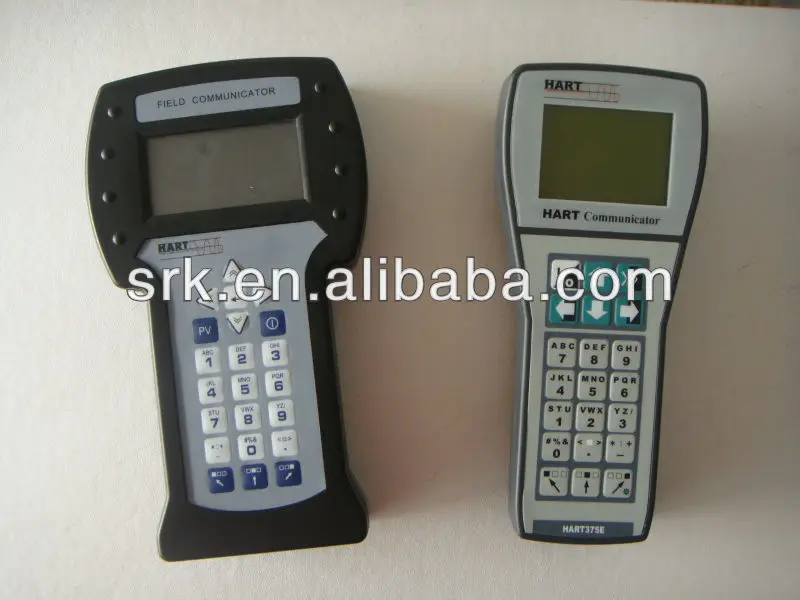
Операцию
обновления может выполнить инженер сервисного центра на предприятии
Заказчика. По усмотрению сервисного
специалиста
за услуги может взиматься дополнительная плата. В любом заказе на обновление
коммуникатора
должен
указываться серийный номер системной карты, который можно узнать, установив
связь между переносным
коммуникатором
модели 475 и программной утилитой Easy Upgrade версии 1.6.0 (или более поздней). Уведомление
о новых
лицензиях, доступных для загрузки может быть отправлено на электронный адрес,
указанный в заказе.
(5)Для
системных карт с истекшим сроком действия опции Easy
Upgrade, в течение 90 дней доступна возможность
продления
действия этой опции на 3 года. Дату окончания действия лицензии можно узнать,
установив связь между
полевым
коммуникатором модели 475 и программной утилитой Easy
Upgrade версии 1.6.0 (или более поздней).
(6)Требуется
программное обеспечение AMS Device Manager (версии 6.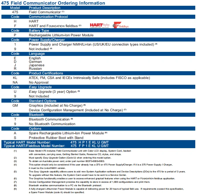
2 или более поздней). Программное
обеспечение
AMS Device Manager
и интерфейс полевого коммуникатора доступны для приобретения только через
официальные каналы продаж.
КОМПЛЕКТ ПОСТАВКИ
Примечание: указанный перечень принадлежностей входит в
комплект поставки любого коммуникатора.
Список принадлежностей, заказываемых дополнительно, указан
выше
PDF Viewer
|
||||||||||||||||||||||||||||||||
|
© 2023 ООО “НПО Промэлектроавтоматика”. Основано в 1997 г. |
 ru
ru
EMERSON 475 РУКОВОДСТВО ПОЛЬЗОВАТЕЛЯ Скачать Pdf
Содержание
5
-
страница
из
114 - Содержание
- Оглавление
- Поиск неисправностей
- Закладки
Реклама
СОДЕРЖАНИЕ
-
СОДЕРЖАНИЕ
-
СОДЕРЖА0035
-
Device Interoperability
- Working in a Hazardous Area
-
Battery and Power Supply/Charger
-
Using the Touch Screen
-
Using the Keypad
-
Memory
-
Accessories
-
-
Сборка
-
Установка системной карты и аккумулятора
-
Извлечение аккумулятора и системной карты
-
-
Starting up and Shutting down
-
Starting up
-
The Field Communicator Main Menu
-
Entering Standby
-
Shutting down
-
-
Settings
-
About Полевой коммуникатор
-
Подсветка
-
Контраст
-
Лицензия
-
Память
-
Состояние мощности
-
ПЕРСОНАЦИЯ ДЛЯ АТКЮТ
- .
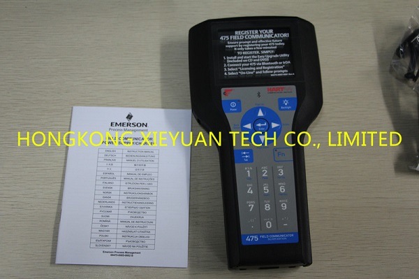
-
Диспетчер устройств AMS
-
Полевой коммуникатор Easy Upgrade Utility
-
Подключение полевого коммуникатора модели 475 или системной карты
-
Upgrading the 475 Field Communicator
-
Adding Functionality by Enabling Licenses
-
-
Scratchpad
-
Creating a New Document
-
Opening an Existing Document
-
-
Maintenance
-
Запуск самотестирования
-
Калибровка
-
-
Секция 3
-
HART Functionality
-
Overview
-
Safety Messages
-
Basic Features and Functions
-
HART Application Functionality
-
Using a Fast Key Sequence
-
-
Starting the HART Application
-
Работа с автономными конфигурациями
-
Создание новой конфигурации
-
Открытие сохраненной конфигурации
-
Передача конфигураций в приложение для ПК
-
-
Работа в Интернете с устройствами HART
-
Подключение к устройству HART
-
Отображение Device Devices HART
- 111269.
 1
1
9.1
- 9
-
Отображение параметров настройки устройства
-
Отображение графики
6. ICRENTIENTIENTIENTIE
Сохранение конфигурации устройства
-
-
Настройка HART Application
-
Использование горячих клавиш
-
Изменение вариантов опроса HART
-
Игнорирующие статус Сообщения
-
. Очистка
-
Просмотр доступных описаний устройств
-
Моделирование онлайн-подключения к устройству HART
-
-
Running HART Diagnostics
-
DC Voltage Measurement (HART Terminals)
-
-
Disconnecting from Ahart Device
-
Section 4
-
Fieldbus Functionality
-
Overview
-
Safety Messages
-
Основные характеристики и функции
-
Функциональность приложения Fieldbus
-
Link Active Scheduler (LAS)
-
LAS Hierarchy
-
-
Starting the FOUNDATION Fieldbus Application
-
Working Online with Fieldbus Devices
-
Connecting to a Fieldbus Device
-
Displaying the Connected Fieldbus Devices
-
Displaying the Блоки устройств
-
Отображение меню устройства
-
Режимы блоков
-
Блоки устройств
-
Отображение графики
-
-
Настройка приложения Foundation Fieldbus
-
Изменение поля
- .
.9002.
.1002.1002626.9002.
2. Доступные
26262626262. 9002. Device
2.1002626625
. Диагностика
-
Измерение постоянного напряжения
-
Измерение уровня шума
-
Signal Level Measurement
-
-
Disconnecting from Afieldbus Device
-
Overview
-
Troubleshooting Suggestions
-
-
Error and Status Messages
-
General Error Messages
-
HART Error Messages
-
Сообщения об ошибках Fieldbus
-
-
Информация для технической поддержки
-
APPENDIX A Processor and Memory Specifications
-
Microprocessor
-
Memory
-
-
Physical Specifications
-
Weight
-
Display
-
Keypad
-
-
Usage Specifications
-
Температурные ограничения
-
Хранение с батареями
-
Общие указания
-
-
Connection Specifications
-
HART and Fieldbus Communication Terminals
-
Connection Types
-
-
Battery Specifications
-
Battery Type
-
Connection
-
Charge
-
Освещение
-
Время работы
-
Хранение
-
-
Power Supply/Charger Specifications
-
Connection
-
Voltage
-
Technical Data
-
-
Order Information
-
Spare Parts List
-
Appendix B
-
Overview
-
Утвержденные производственные предприятия
-
Информация о директивах ЕС — соответствие требованиям ЕС
-
Electro Magnetic Compatibility (2004/108/EC
-
ATEX Directive (94/9/EC) (KL Option Only
-
-
Hazardous Locations Certifications (KL Option Only
-
European Certifications
-
Международная сертификация
-
Североамериканские сертификаты
-
-
Чертежи этикеток
-
Сертификация блока питания/зарядного устройства
-
Declaration of Conformity/Approvals
-
-
Approval Drawings
-
Appendix C
-
Overview
-
Screen Layout
-
Buttons
-
Graphics Options
-
Images
-
Диаграммы
-
Графики
-
-
Глоссарий
ПОЛЬЗОВАТЕЛЬСКАЯ
РУКОВОДСТВО
Содержание
Предыдущая страница
Следующая страница
Содержание
Краткое содержание для Emerson 475
Полевой коммуникатор Emerson 475
Полевой коммуникатор Emerson 475
Производитель:
Эмерсон
Модель:
475ФБ
Пожалуйста, выберите вариант ниже
Варианты продукта
Аренда
Купить новый
Купить б/у
Пожалуйста, выберите количество
123456789101112
Подробная информация о продукте
Полевой коммуникатор Emerson 475 — это портативный коммуникатор, обеспечивающий универсальную поддержку устройств HART и Foundation Fieldbus.
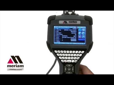
-
-

Introduction
3
©
2009
Emerson Process Management. All rights reserved.
HART is a registered trademark of the HART Communication Foundation.
F
OUNDATION
is a trademark of the Fieldbus Foundation.
IrDA is a registered trademark of the Infrared Data Association.
Bluetooth is a registered trademark of the Bluetooth SIG, Inc.
AMS Suite is a registered trademark of Emerson Electric Co.
The Emerson logo is a trademark and service mark of Emerson Electric Co.
All other marks are the property of their respective owners.
INTRODUCTION
The
475 Field Communicator Getting Started Guide
provides basic guidelines,
precautions, and setup information for the 475 Field Communicator. It does not provide
in-depth instructions for configuration, diagnostics, maintenance, service,
troubleshooting, or Intrinsically Safe (IS) installations. Refer to the
475 Field
Communicator User’s Manual
on the Resource CD or www.fieldcommunicator.com for
more instructions.
The 475 Field Communicator supports HART and F
OUNDATION
fieldbus devices, letting
you configure or troubleshoot in the field. Electronic Device Description Language
(EDDL) technology enables the 475 Field Communicator to communicate with a
variety of devices independent of device manufacturer.
WARNING
Explosions could result in serious injury or death:
Use in an explosive environment must be in accordance with the appropriate local,
national, and international standards, codes, and practices. Please review the
Reference Information and Product Certifications sections of the
475 Field
Communicator User’s Manual
for any restrictions associated with safe use.
Electrical shock can result in serious injury or death.
WARNING
This device complies with Part 15 of the FCC Rules. Operation is subject to the
following two conditions: (1) this device may not cause harmful interference, and (2)
this device must accept any interference received, including interference that may
cause undesired operation.

475 Field Communicator Overview
4
475 FIELD COMMUNICATOR OVERVIEW
The portable 475 Field Communicator includes a color LCD touch screen, a Lithium
Ion battery (Power Module), a SH3 processor, memory components, and integral
communication and measurement circuitry.
When using the 475 Field Communicator to communicate with devices, follow all
standards and procedures applicable to the location. Failure to comply may result in
equipment damage and/or personal injury. Understand and comply with the sections in
this manual.
Working in a Hazardous Area
An Intrinsically Safe (IS-approved) 475 Field Communicator can be used in Zone 0
(FM and CSA only), Zone 1, or Zone 2,
for Group IIC, and Class I, Division 1 and
Division 2, Groups A, B, C, and D locations.
An IS-approved 475 Field Communicator may be connected to loops or segments that
are attached to equipment located in Zone 0, Zone 1, Zone 2,
for Group IIC; Zone 20,
Zone 21, Zone 22,
and Class I, Division 1 and Division 2,
Groups A, B, C, and D
locations.
IS-approved 475 Field Communicators are ordered with the KL option and have an
additional label on the back of the communicator that lists the approvals.
CAUTION
You can install or remove the Li-Ion battery in a hazardous area environment. You
cannot charge the battery in this environment because the power supply/charger
(00375-0003-0005) is not IS-approved.
Using the Touch Screen and Keypad
The touch screen and keypad let you select menu items and enter text. Tap the screen
with the provided stylus or use the up and down arrow keys on the keypad to select a
menu item. See Figure 1 for the location of the stylus. Double-tap the selected item on
the screen or press the right arrow key on the keypad to open a menu item.
CAUTION
Contact the touch screen using blunt items only, preferably the stylus included with the
475 Field Communicator. Sharp instruments, such as screwdrivers, can damage the
touch screen and void the warranty. Repairing the touch screen requires replacement
of the entire display assembly, which is possible only at an authorized service center.

475 Field Communicator Overview
5
Figure 1. 475 Field Communicator
HART and F
OUNDATION
fieldbus Communication
Terminals (top)
Stylus (in the
strap)
Bluetooth
®
Light
IrDA
®
Interface (top)
Touch Screen
Display
Strap attachment
(top)
Backlight Key
Strap
Attachment
(side)
Enter Key
Function Key
and Light
(for multiple-key
combination
functionality)
Li-Ion Battery
(back) and
System Card
(internal)
Strap Attachment (side)
Strap Attachment (side)
Lights
Illuminated by
Pressing the
Charge Indicator
Button (side)
Alphanumeric
Keypad
Tab Key
Navigation Keys
(four arrow keys)
Strap
Attachment
(side)
Power Key and
Light
Charge
Indicator
Button (side)
Green Power
Supply/Charger
Connector on
the Battery
(side)

475 Field Communicator Overview
6
Battery and Power Supply/Charger
Understand and follow the precautions below before using your battery or power
supply/charger.
• Protect the battery and power supply/charger from moisture, and respect operating
and storage temperature limits. See the
475 Field Communicator User’s Manual
for
temperature limits.
• Do not cover the battery or power supply/charger, subject it to prolonged periods of
direct sunlight, or place it upon or next to heat-sensitive materials.
• Charge the battery with only the power supply/charger. The power supply/charger
should not be used with other products. Failure to comply may permanently damage
your 475 Field Communicator and void the IS approval and the warranty.
• Do not open or modify the battery or power supply/charger. There are no
user-serviceable components or safety elements inside. Opening or modifying them
will void the warranty and could cause personal harm.
• Follow all applicable regulations when transporting a Li-Ion battery.
Charging the Battery
Prior to first portable use, fully charge the Li-Ion battery. The power supply/charger has
a green connector to match the connector on the battery. The battery can be charged
separately or while attached to the 475 Field Communicator. A full charge takes
approximately two to three hours, and the 475 is fully operable when charging. An
overcharge condition will not occur if power supply/charger remains connected after
charging completes.
To maintain performance, charge the battery frequently, preferably after each use. Limit
full discharges, if possible. Additional information about maintaining the battery is in the
475 Field Communicator User’s Manual
.
Power Supply/Charger Lights
Three colored lights are on the power supply/charger to indicate the conditions below.
Each light displays a different color.
Color
Condition
Green
The battery is fully charged.
Flashing green
The battery is nearly fully charged.
Amber
The battery is charging.
Flashing amber
The power supply/charger is not connected to the
475 Field Communicator.
Flashing amber and red
The remaining charge in the battery is low.
Red
Charging cannot occur. Contact Technical Support for
more information.

Installing the System Card and Battery
7
Figure 2. Back of the 475 Field Communicator
INSTALLING THE SYSTEM CARD AND BATTERY
1. Remove the protective rubber boot, if attached.
2. Place the 475 Field Communicator face down on a level, secure surface.
3. With the battery removed, slide the Secure Digital System Card (labeled System
Card), with the card contacts facing up, into the System Card socket until it clicks.
See Figure 2. The System Card socket is spring-loaded.
CAUTION
The System Card must be supplied by the 475 Field Communicator manufacturer.
Failure to comply will void the IS approval.
4. With the 475 Field Communicator still face down, ensure the two battery retaining
screws are loose.
5. Align the battery with the sides of 475 Field Communicator, and carefully slide the
battery forward until it is secure.
CAUTION
The connector pins may be damaged if the battery and 475 Field Communicator are
improperly aligned.
6. Carefully hand tighten the two battery retaining screws. (Do not over tighten, 0.5Nm
maximum torque load.) The tops of the screws should be nearly flush with the 475
Field Communicator.
Battery Retaining Screws
Li-Ion Battery
Connector Pins
System Card in the
System Card Socket
Main Unit Label
Strap Attachment
Strap Attachment
IS Label
Location
(KL Option)
Stand

Removing the Battery and System Card
8
REMOVING THE BATTERY AND SYSTEM CARD
1. Remove the protective rubber boot, if attached.
2. With the 475 Field Communicator off, place it face down on a level, secure surface.
3. Loosen the two battery retaining screws until the top of each screw is above the top
of the 475 Field Communicator.
4. Slide the battery off the 475 Field Communicator.
CAUTION
The connector pins may be damaged if you pull the battery up rather than slide it off
the 475 Field Communicator.
5. Push the System Card into the System Card socket until it clicks and releases.
6. Slide the System Card out of the System Card socket.
STARTING THE 475 FIELD COMMUNICATOR
Before startup, ensure the 475 Field Communicator is not damaged, the battery is fully
seated, all screws are sufficiently tightened, and the communication terminals are free
of dirt and debris.
To start the 475 Field Communicator:
1. Press and hold the Power key on the keypad until the green light on that key blinks
(approximately two seconds). During startup, the 475 Field Communicator notifies
you if an upgrade on the System Card needs to be installed. The Field
Communicator Main Menu displays.
2. Use the touch screen or up and down arrow keys to select menu items. To open a
selected menu item, double-tap it or use the right arrow key.
3. To shut down, press the Power key and tap
Shut down
from the Power Switch
screen. Tap
OK
.
COMMUNICATING WITH PC APPLICATIONS
The IrDA interface, Bluetooth interface (if licensed), and a supported card reader let
the 475 Field Communicator or its System Card communicate with a PC. See Figure 1
for the location of the IrDA interface and the System Card. A card reader can only be
used with the Easy Upgrade Utility. See the
475 Field Communicator User’s Manual
for
more information.

Connecting to a Device
9
CONNECTING TO A DEVICE
Use the provided lead set to connect the 475 Field Communicator to the loop,
segment, or device. Three communication terminals for the lead set are on the top of
the 475 Field Communicator. Each red terminal is a positive connection for its protocol,
and the black terminal is a common terminal shared by both protocols. An access door
ensures that only one pair of terminals is exposed at any one time. Several markings
indicate which pair of terminals is for which protocol.
Only connections to a HART loop and F
OUNDATION
fieldbus segment are allowed. After
the device is connected, double-tap
HART Application
or
F
OUNDATION
Fieldbus
Application
from the Field Communicator Main Menu. The appropriate device
description is also required. Refer to the latest version of the
475 Field Communicator
User’s Manual
for details.
CAUTION
The 475 Field Communicator draws approximately 12 mA from the fieldbus segment.
Ensure the power supply or barrier on the fieldbus segment has the capacity to provide
this additional current. If a fieldbus segment is drawing near the capacity of the
segment’s power supply, connecting the 475 Field Communicator may result in loss of
communication.
TECHNICAL SUPPORT
Contact your supplier or go to http://www.fieldcommunicator.com/supp.htm for
Technical Support contact information.
MAINTENANCE AND REPAIR
Any maintenance, repair, or replacement of components not listed below must be
performed by specially trained personnel at an authorized service center. You can
perform common maintenance procedures listed below:
• Cleaning the exterior. Use only a dry, lint-free towel or dampen the towel with a mild
soap and water solution.
• Charging, removing, and replacing the battery.
• Removing and replacing the System Card.
• Removing and replacing the stand.
• Ensuring that all exterior screws are sufficiently tightened.
• Ensuring that the communication terminal recess is free of dirt and debris.

Waste Disposal
10
WASTE DISPOSAL
Products with the following label comply with the Waste Electrical and Electronic
Equipment (WEEE) directive, 2002/96/EC, which applies to European Union (EU)
member states only.
The label indicates this product should be recycled and not treated as
household waste. Customers in EU member states should contact their
Emerson sales representative for information on discarding any part of the
475 Field Communicator.
For customers in all other world areas, if it is necessary to discard any part of the 475
Field Communicator, follow the waste-disposal regulations applicable in your location.
HAZARDOUS SUBSTANCES
Products with the following label are lead-free and comply with the Restriction of the
Use of Certain Hazardous Substances in Electrical and Electronic Equipment (RoHS)
directive, 2002/95/EC, which applies to EU member states only.
The purpose of the directive is to limit the use of lead, cadmium, mercury,
hexavalent chromium, polybrominated biphenyl (PBB), and polybrominated
diphenyl ether (PBDE) flame retardants in electronic equipment.
PRODUCT CERTIFICATIONS
Overview
All 475 Field Communicators have the main unit label (see Figure 2). Intrinsically Safe
(KL option) 475 Field Communicators also have a label opposite the main unit label. If
the 475 Field Communicator does not contain this label (NA option), it is not
Intrinsically Safe. See the
475 Field Communicator User’s Manual
or
www.fieldcommunicator.com for additional approval information.
The Industry Canada (IC), Federal Communications Commission (FCC), and Radio
and Telecommunications Terminal Equipment (R&TTE) approvals apply to only 475
Field Communicators licensed for Bluetooth.
Approved Manufacturing Locations
Emerson Process Management — Leicester, England
IC
This Class A digital apparatus complies with Canadian ICES-003.
RoHS
Pb

Product Certifications
11
FCC
This equipment has been tested and found to comply with the limits for a Class A
digital device, pursuant to part 15 of the FCC Rules. These limits are designed to
provide reasonable protection against harmful interference when the equipment is
operated in a commercial environment. This equipment generates, uses, and can
radiate radio frequency energy and, if not installed and used in accordance with the
instruction manual, may cause harmful interference to radio communications.
Operation of this equipment in a residential area is likely to cause harmful interference
in which case the user will be required to correct the interference at his own expense.
Any modifications made to this device that are not approved by Emerson Process
Management may void the authority granted to the user by the FCC to operate this
equipment.
European Directive Information
—
CE Compliance
Electromagnetic Compatibility (2004/108/EC)
Tested to the EN 61326-1 specification.
R&TTE
This equipment complies with the Radio and Telecommunications Terminal
Equipment (1999/5/EC) Directive.
ATEX Directive (94/9/EC) (KL option only)
Emerson Process Management complies with the ATEX Directive. Applicable
standards are EN 60079-0, EN 60079-11, EN 60079-26, and EN 60079-27.
Specific ATEX Directive Information is located within this document and the
475 Field Communicator User’s Manual
.
Hazardous Locations Certifications (KL option only)
The Intrinsic Safety approvals listed in this section include compliance with the FISCO
requirements.
North American Certifications
Factory Mutual (FM)
Intrinsically Safe for Class I, Division 1, Groups A, B, C, and D and Class I,
Zone 0, AEx ia IIC T4 (Ta = 50°C) hazardous locations when connected as
indicated in the control drawing 00475-1130 in the
475 Field Communicator
User’s Manual
. See the control drawing for input and output parameters.
Canadian Standards Association (CSA)
Intrinsically Safe for use in Class I, Zone 0, Ex ia IIC T4 (Ta = 50°C) hazardous
locations when connected as indicated in the control drawing 00475-1130 in
the
475 Field Communicator User’s Manual
. See the control drawing for input
and output parameters.

Product Certifications
12
International Certification
IECEx
Certification No.: BVS 09.0012
Ex ia IIC T4 (-10°C
≤
Ta
≤
50°C)
European Certifications
ATEX Intrinsic Safety
Certification No.: BVS 09 ATEX E 023
II 2 G (1 GD) Ex ia IIC T4 (-10°C
≤
Ta
≤
+50°C)
1180
HART Intrinsically Safe Electrical Parameters
F
OUNDATION
fieldbus
The FISCO standard applies to the FM, CSA, IECEx, and ATEX certifications.
Input Parameters
U
i
= 30 Volt DC
I
i
= 200 mA
P
i
= 1.0 Watt
L
i
= 0
C
i
= 0
Output Parameters
U
0
= 1.9 Volt DC
I
0
= 32
μ
A
Intrinsically Safe FISCO
U
iIIC
= 17.5 Volt DC
I
iIIC
= 215 mA
P
iIIC
= 1.9 Watt
U
iIIB
= 17.5 Volt DC
I
iIIB
= 380 mA
P
iIIB
= 5.3 Watt
U
0
= 1.9 Volt DC
I
0
= 32 µA
Intrinsically Safe Non-FISCO
U
i
= 30 Volt DC
I
i
= 380 mA
P
i
= 1.3 Watt
U
0
= 1.9 Volt DC
I
0
= 32 µA
L
i
= 0
C
i
= 0