
- Manuals
- Brands
- Grundfos Manuals
- Engine
- MGE 90 Series
Manuals and User Guides for Grundfos MGE 90 Series. We have 4 Grundfos MGE 90 Series manuals available for free PDF download: Installation And Operating Instructions Manual, Service Instructions Manual
Внимание к мелочам — черта профессионалов
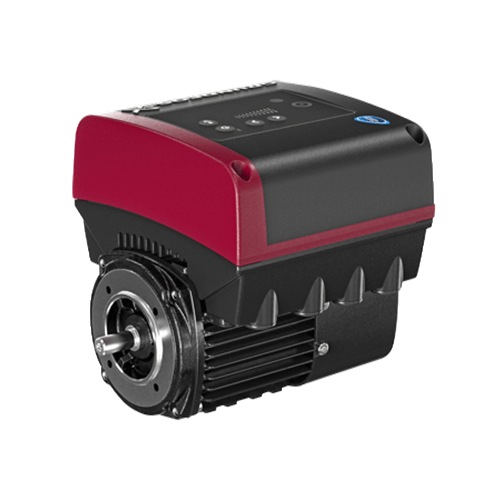
![]()
Заказать
Данные каталога MGE90LD
| Наименование продукции | MGE90LD |
| Производственный номер | 98190193 |
| EAN номер | 5711491196251 |
Описание MGE90LD
Основные данные MGE90LD
| Данные на табличке электродвигателя | CE,C-TICK |
| Модель | I |
| Охлаждение | IC 411 |
Изображение MGE90LD

Примечание к изображению: Внимание! Фотография продукта может отличаться от существующего.
Данные электрооборудования MGE90LD
| Тип электродвигателя | 90LD |
| Номинальная мощность — P2 | 2.2 кВт |
| Промышленная частота | 50 Hz |
| Номинальное напряжение | 3 x 380-500 V |
| Номинальный ток | 4,15-3,40 A |
| Cos фи — характеристика мощности | 0,93-0,87 |
| Номинальная скорость | 360-4000 об/м |
| Номинальный вращающий момент при полной нагрузке | 7.2 Нм |
| Момент инерции | 0.0007 кг м2 |
| Энергоэффективность | 89,0% |
| Класс защиты (IEC 34-5) | IP55 |
| Класс изоляции (IEC 85) | F |
| Защита электродвигателя | Да |
| Тепловая защита | ELEC |
| Направление вращения | CW |
| Монтажн. обозначение по IEC 34-7 | IM B14/V18 |
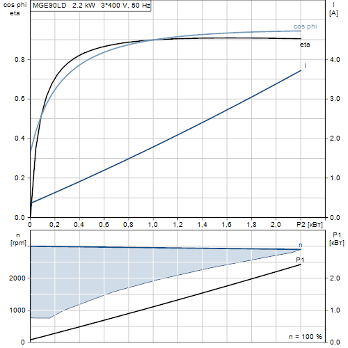
Характеристика двигателя MGE90LD
Монтаж MGE90LD
| Диапазон температуры окружающей среды | -20 .. 50 °C |
| Размер фланца электродвигателя | FT115 |
Устр-ва управл-ия MGE90LD
| Панель управления | HMI200 — Стандарт |
| Общ.модуль | НЕТ |
| Функциональный модуль | FM300 — Advanced (Расширенный) |
Другое MGE90LD
| Маркировка | Grundfos Blueflux |
| Нетто вес | 15 кг |
| № структурного файла | 98373207 |
Габаритный чертеж MGE90LD
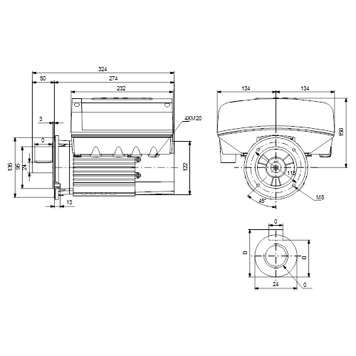
| Примечание | Правовая оговорка |
| Внимание! Все величины даны в [мм], если не указано иное. | На данном упрощённом габаритном чертеже представлены не все компоненты. |
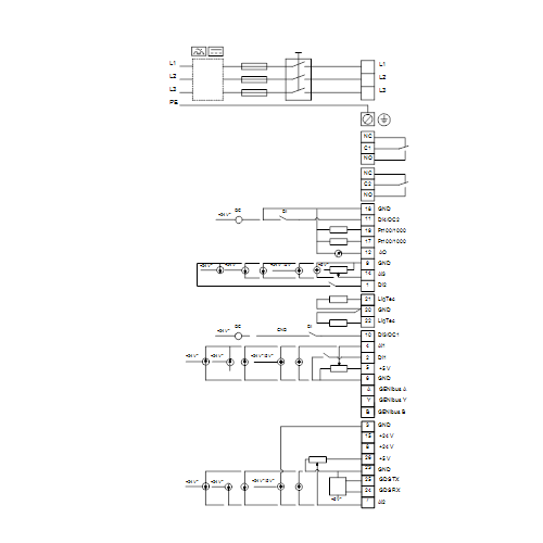
Схема подключений MGE90LD


-
Contents
-
Table of Contents
-
Bookmarks
English (GB) Installation and operating instructions
Original installation and operating instructions
CONTENTS
1.
2.
3.
3.1
3.2
4.
4.1
4.2
5.
5.1
5.2
6.
6.1
6.2
6.3
6.4
6.5
6.6
7.
7.1
7.2
7.3
7.4
7.5
7.6
7.7
7.8
8.
8.1
8.2
8.3
8.4
8.5
9.
9.1
9.2
9.3
9.4
9.5
10.
10.1
10.2
10.3
10.4
10.5
10.6
10.7
10.8
2
10.9
10.11
Page
3
3
4
4
4
5
5
6
7
7
7
7
7
7
7
7
8
8
8
8
9
9
10
11
11
16
16
17
17
17
17
17
17
18
11.
18
12.
19
13.
21
14.
26
30
15.
32
16.
32
17.
32
32
18.
32
32
19.
33
20.
34
21.
35
36
36
37
37
37
40
41
42
42
42
42
42
43
43
43
43
43
43
43
44
44
44
44
44
44
44
45
45
45
45
45
46
46
46
49
49
49
50
51
52
54
54
55
56
56
57
58
Перейти к контенту
-
Bookmarks
Quick Links
GRUNDFOS INSTRUCTIONS
MGE
Antenna
Service kit instructions
Related Manuals for Grundfos MGE Series
Summary of Contents for Grundfos MGE Series
-
Page 1
GRUNDFOS INSTRUCTIONS Antenna Service kit instructions… -
Page 3
English (GB) Service kit instructions CONTENTS Page 1. Dismantling 2. Assembly English (GB) Warning Before starting service work, read the safety instructions supplied with the product. Always use an antistatic service kit when handling electronic components. This will prevent static electricity from damaging components. -
Page 4
Deutsch (DE) Warnung Vor der Durchführung irgendwelcher Reparaturarbeiten ist die mit dem Produkt mitgelieferte Serviceanleitung sorgfältig durchzulesen. Bei m Umgang mit elektronischen Bauteilen ist immer ein antistatischer Erdungsreparatursatz zu verwenden. Dadurch wird verhindert, dass die Bauteile durch statische Entladung beschädigt werden. Siehe nachfolgende Abbil- Caution dung. -
Page 5
Français (FR) Avertissement Avant toute intervention, consulter les consignes de mainte- nance fournies avec le produit. Toujours utiliser un kit de maintenance antistatique lors de la manipulation de composants électroniques. Cela évite que l’électricité statique n’endommage les composants. Caution Voir figure ci-dessous. Lorsqu’il n’est pas protégé, le composant doit être placé… -
Page 6
Português (PT) Aviso Antes de iniciar o serviço de manutenção, leia as instruções de segurança fornecidas com o produto. Utilize sempre um kit de manutenção antiestático quando lidar com componentes electrónicos. Isto irá prevenir que a electricidade estática danifique os componentes. Caution Observe a figura abaixo. -
Page 7
Svenska (SE) Varning Läs de säkerhetsanvisningar som medföljer produkten innan servicearbetet inleds. Använd alltid antistatservicesats vid hantering av elektronik- komponenter. Det förhindrar att komponenter skadas av sta- Caution tisk elektricitet. Se figur nedan. Oskyddade komponenter ska placeras på antistatduk. -
Page 8
1. Dismantling DK: Demontering NL: Demontage DE: Demontage PT: Desmontagem GR: Αποσυναρμολόγηση RU: Демонтаж ES: Desmontaje FI: Purkaminen FR: Démontage SE: Demontering IT: Smontaggio TX25 x 4 Fig. 1… -
Page 9
Fig. 2 Fig. 3… -
Page 10
2. Assembly DK: Montering NL: Montage DE: Montage PT: Montagem GR: Συναρμολόγηση RU: Подключение ES: Montaje FI: Kokoaminen FR: Montage SE: Montering IT: Montaggio 27 mm Size Torque [Nm] 1 — 1.5 Fig. 4… -
Page 11
27 mm Size Torque [Nm] Fig. 5 Fig. 6… -
Page 12
Fig. 7… -
Page 13
Fig. 8… -
Page 14
TX25 x 4 Size Torque [Nm] Fig. 9… -
Page 18
Argentina China Germany Bombas GRUNDFOS de GRUNDFOS Pumps GRUNDFOS GMBH Argentina S.A. (Shanghai) Co. Ltd. Tel.: +49-(0) 211 929 69-0 Phone: +54-3327 414 444 Phone: +86-021-612 252 22 e-mail: infoservice@grund- Telefax: +54-3327 411 111 Telefax: +86-021-612 253 fos.de Service in Deutschland:… -
Page 19
Telefax: +386 1 568 0619 Telefax: +31-88-478 6332 s U.S.A. South Africa New Zealand GRUNDFOS Pumps Corpo- GRUNDFOS (PTY) LTD GRUNDFOS Pumps NZ Ltd. ration Phone: (+27) 11 579 4800 Phone: +64-9-415 3240 Phone: +1-913-227-3400 Fax: (+27) 11 455 6066 Telefax: +64-9-415 3250… -
Page 20
98273054 0213 ECM: 1109804 www.grundfos.com www.grundfos.com…
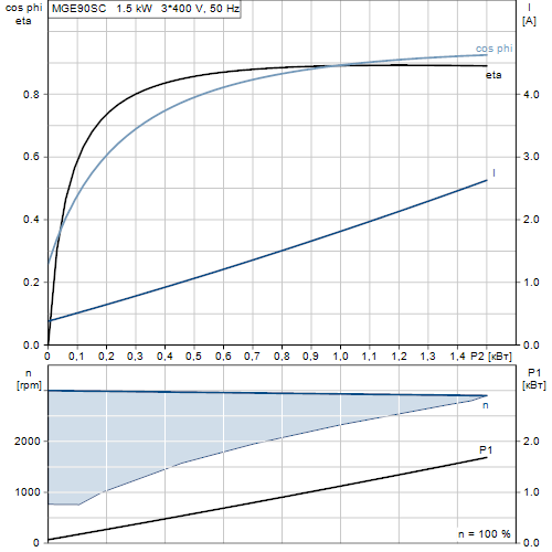
Внимание к мелочам — черта профессионалов
![]()
Заказать
Данные каталога MGE90SC
| Наименование продукции | MGE90SC |
| Производственный номер | 98190189 |
| EAN номер | 5711491196213 |
Описание MGE90SC
Основные данные MGE90SC
| Данные на табличке электродвигателя | CE,C-TICK |
| Модель | I |
| Охлаждение | IC 411 |
Изображение MGE90SC
Примечание к изображению: Внимание! Фотография продукта может отличаться от существующего.
Данные электрооборудования MGE90SC
| Тип электродвигателя | 90SC |
| Номинальная мощность — P2 | 1.5 кВт |
| Промышленная частота | 50 Hz |
| Номинальное напряжение | 3 x 380-500 V |
| Номинальный ток | 2,90-2,40 A |
| Cos фи — характеристика мощности | 0,92-0,84 |
| Номинальная скорость | 360-4000 об/м |
| Номинальный вращающий момент при полной нагрузке | 5 Нм |
| Момент инерции | 0.0005 кг м2 |
| Энергоэффективность | 88,0% |
| Класс защиты (IEC 34-5) | IP55 |
| Класс изоляции (IEC 85) | F |
| Защита электродвигателя | Да |
| Тепловая защита | ELEC |
| Направление вращения | CW |
| Монтажн. обозначение по IEC 34-7 | IM B14/V18 |
Характеристика двигателя MGE90SC
Монтаж MGE90SC
| Диапазон температуры окружающей среды | -20 .. 50 °C |
| Размер фланца электродвигателя | FT115 |
Устр-ва управл-ия MGE90SC
| Панель управления | HMI200 — Стандарт |
| Общ.модуль | НЕТ |
| Функциональный модуль | FM300 — Advanced (Расширенный) |
Другое MGE90SC
| Маркировка | Grundfos Blueflux |
| Нетто вес | 14 кг |
| № структурного файла | 98373206 |
Габаритный чертеж MGE90SC

| Примечание | Правовая оговорка |
| Внимание! Все величины даны в [мм], если не указано иное. | На данном упрощённом габаритном чертеже представлены не все компоненты. |
Схема подключений MGE90SC

You can identify the motor by means of the
nameplate on the terminal box.
4.1 Nameplate
The motor nameplate is located on the side of the
terminal box. See fig. 1, pos. A.
Type :
P.C. :
INPUT
P.N. :
Serial no :
U
in
:
~
DE :
Env.Type :
TEFC
NDE :
SF
:
CL:
f
:
in
Wgt :
kg
T
amb
:
F
PF:
I
SF Amp
:
A
Fig. 1
Nameplate location
Figure
2
shows the nameplate. The position
numbers refer to the table below.
1
2
3
4
Type :
P.C. :
P.N. :
— V
DE :
Env.Type :
NDE :
PF
:
o
Wgt :
kg
T
:
amb
27
26
25
24
Fig. 2
Nameplate, MGE motors
Pos.
Description
1
Type designation
2
Product number
3
Drive-end bearing
4
Version number
5
Environmental type
6
Production code (year and week)
7
Supply voltage [V]
8
Rated power output [kW]
9
Power board
10
Functional module type
11
CE mark and approvals
12
Part number of nameplate
13
Grundfos logo
14
Grundfos company address
OUTPUT
VARIANT
P2
:
Hp
PB
:
V
n max:
rpm
FM
:
Hz
Eff
:
HMI
:
Made in Hungary
I
1/1
:
A
CIM
:
DK — 8850 Bjerringbro, Denmark
A
5
6
7
INPUT
U in
:
IP:
~
CL:
f in
:
C
I
:
1/1
23
22
21
20
8
9
10
OUTPUT
VARIANT
P2
:
kW
PB
:
V
n max:
rpm
FM
:
Hz
Eff
:
HMI
:
:
A
CIM
19
18
17
16
Pos.
Description
15
Country of origin
16
Human Machine Interface type
17
CIM module type
18
Motor efficiency
19
Maximum motor speed [min
20
Maximum input current [A]
21
Mains frequency [Hz]
Enclosure class according to IEC
22
60034-5
23
Insulation class according to IEC 62114
24
Maximum ambient temperature [°C]
25
Power factor
26
Weight [kg]
27
Non-drive-end bearing
11
12
Made in Hungary
DK — 8850 Bjerringbro, Denmark
15
14
13
-1
]
5
 |
[Page 1] Grundfos MGE Series MGE motors Installation and operating instructions GRUNDFOS INSTRUCTIONS |
 |
[Page 2] Grundfos MGE Series English (GB) 2 English (GB) Installation and operating instructions Original installation and operating instructions CONTENTS Page 1. Symbols used in this document 3 2. Abbreviations and definitions 3 3. General description 4 3.1 Radio communication … |
 |
[Page 3] Grundfos MGE Series English (GB) 3 1. Symbols used in this document 2. Abbreviations and definitions 22. Technical data, single-phase motors 58 22.1 Supply voltage 58 22.2 Leakage current 58 23. Technical data, three-phase motors 58 23.1 Supply voltage 58 23.2 Leakage… |
 |
[Page 4] Grundfos MGE Series English (GB) 4 3. General description Grundfos MGE 71-160 are frequency-controlled permanent-magnet motors for single-phase or three-phase mains connection. The motors incorporate a PI controller. You can connect the motors to a signal from an ex… |
 |
[Page 5] Grundfos MGE Series English (GB) 5 4. Identification You can identify the motor by means of the nameplate on the terminal box. 4.1 Nameplate The motor nameplate is located on the side of the terminal box. See fig. 1, pos. A. Fig. 1 Nameplate location Figure 2 shows t… |
 |
[Page 6] Grundfos MGE Series English (GB) 6 4.2 Type key 1) Frame size 71, 80, 90 2) Frame size 100, 112, 132, 160 Code Example MG E 71 M A 2- FT 85 -H A [ ] B K Type of motor unit Complete motor with terminal box Basic motor unit without terminal box Kit for basic motor unit wi… |
 |
[Page 7] Grundfos MGE Series English (GB) 7 5. Receiving the product 5.1 Transporting the product • Motors from 2.2 to 5.5 kW: Do not stack more than two motors in their original packaging. • Motors from 5.5 to 11 kW: Do not stack the motors. 5.2 Inspecting the product Bef… |
 |
[Page 8] Grundfos MGE Series English (GB) 8 6.5 Outdoor installation If you install the motor outdoors, provide the motor with a suitable cover and open the drain holes to avoid condensation on the electronic components. See figures 4 and 5. The cover must be sufficiently lar… |
 |
[Page 9] Grundfos MGE Series English (GB) 9 7.2 Cable requirements 7.2.1 Cable cross-section Single-phase supply Three-phase supply 7.2.2 Conductors Type Stranded or solid copper conductors. Temperature rating Temperature rating for conductor insulation: 60 °C (140 °F). Tempe… |
 |
[Page 10] Grundfos MGE Series English (GB) 10 7.3.2 Three-phase supply voltage • 3 x 380-500 V — 10 %/+ 10 %, 50/60 Hz, PE. Check that the supply voltage and frequency correspond to the values stated on the nameplate. The wires in the motor terminal box must be as short as po… |
 |
[Page 11] Grundfos MGE Series English (GB) 11 Overload protection If the upper load limit is exceeded, the motor automatically compensates for this by reducing the speed and stops if the overload condition persists. The motor remains stopped for a set period. After this period… |
 |
[Page 12] Grundfos MGE Series English (GB) 12 * If you use an external supply source, there must be a connection to earth. Fig. 10 Connection terminals, FM 100 7.6.2 Standard functional module, FM 200 The module has more inputs and outputs than FM 100 and is suitable for even m… |
 |
[Page 13] Grundfos MGE Series English (GB) 13 * If you use an external supply source, there must be a connection to earth. Fig. 11 Connection terminals, FM 200 TM05 3510 3512 3 15 8 26 23 25 24 7 B Y 6 5 2 4 10 A AI2 GDS RX GDS TX GND GENIbus A GENIbus B +5 V +24 V +24 V GND GEN… |
 |
[Page 14] Grundfos MGE Series English (GB) 14 7.6.3 Advanced functional module, FM 300 The module has a number of inputs and outputs enabling the motor to be used in advanced applications where many inputs and outputs are required. The module has these connections: • three a… |
 |
[Page 15] Grundfos MGE Series English (GB) 15 Terminal Type Function NC Normally closed contact Signal relay 1 (LIVE or PELV) C1 Common NO Normally open contact NC Normally closed contact Signal relay 2 (PELV only) C2 Common NO Normally open contact 18 GND Earth 11 DI4/OC2 Di… |
 |
[Page 16] Grundfos MGE Series English (GB) 16 7.7 Signal cables Use screened cables with a cross-sectional area of minimum 0.5 mm 2 and maximum 1.5 mm 2 for the external on/off switch, digital inputs, setpoint and sensor signals. Connect the screens of the cables to the fra… |
 |
[Page 17] Grundfos MGE Series English (GB) 17 8. Operating conditions 8.1 Maximum number of starts and stops The number of starts and stops via the power supply must not exceed four times per hour. When switched on via the power supply, the motor starts after approximately 5 se… |
 |
[Page 18] Grundfos MGE Series English (GB) 18 9. User interfaces You can make the motor settings by means of the following user interfaces: Control panels • Basic control panel. See section 9.1 Basic control panel. • Standard control panel. See section 9.2 Standard control p… |
 |
[Page 19] Grundfos MGE Series English (GB) 19 9.2 Standard control panel Fig. 18 Standard control panel 9.2.1 Setpoint setting Set the desired setpoint of the motor by pressing or . The green light fields on the control panel indicate the setpoint set. Motor in controlled-op… |
 |
[Page 20] Grundfos MGE Series English (GB) 20 Setting to maximum speed Press continuously to change over to the maximum speed. The top light field flashes. When the top light field is on, press for 3 seconds until the light field starts flashing. To go back, press contin… |
 |
[Page 21] Grundfos MGE Series English (GB) 21 9.3 Advanced control panel The motors can be fitted with the advanced control panel as an option. Fig. 23 Advanced control panel TM05 4849 1013 Pos. Symbol Description 1 Grundfos Eye Shows the operating status of the motor. See s… |
 |
[Page 22] Grundfos MGE Series English (GB) 22 9.3.1 «Home» display Fig. 24 Example of «»Home»» display 9.3.2 Startup guide The motor incorporates a startup guide which is started at the first startup. See section 10.35 «»Run start-up guid… |
 |
[Page 23] Grundfos MGE Series English (GB) 23 9.3.3 Menu overview for advanced control panel 1) Only available if an advanced functional module, type FM 300, is fitted. Advanced control panel «Home» MGE Multimotor system ●● «Status» MGE Multimotor system &… |
 |
[Page 24] Grundfos MGE Series English (GB) 24 Advanced control panel «Settings» MGE Multimotor system Section Page «»Setpoint»» ●●10.1 «»Setpoint»» 32 «»Operating mode»» ●●10.2 «»Operating… |
 |
[Page 25] Grundfos MGE Series English (GB) 25 Continued from page 24. Advanced control panel «Settings» CME Multimotor system Section Page «»Special functions»» ●● «»Ramps»» ●●10.16 «Ramps» 42 «»Stand… |
 |
[Page 26] Grundfos MGE Series English (GB) 26 9.4 Grundfos GO The motor is designed for wireless radio or infrared communication with Grundfos GO. Grundfos GO enables setting of functions and gives access to status overviews, technical product information and actual operating… |
 |
[Page 27] Grundfos MGE Series English (GB) 27 9.4.2 Menu overview for Grundfos GO 1) Only available if an advanced functional module, type FM 300, is fitted. 2) Only available if Grundfos GO is connected to a multimotor system. Dashboard MGE Multimotor system ●● Status MGE Mu… |
 |
[Page 28] Grundfos MGE Series English (GB) 28 Settings MGE Multimotor system Section Page «Setpoint» ●●10.1 «»Setpoint»» 32 «Operating mode» ●●10.2 «»Operating mode»» 32 «Control mode» ●●10.4 «… |
 |
[Page 29] Grundfos MGE Series English (GB) 29 1) Only available if an advanced functional module, type FM 300, is fitted. 2) Only available if Grundfos GO is connected to a multimotor system. Continued from page 29. Settings MGE Multimotor system Section Page «Standstill he… |
 |
[Page 30] Grundfos MGE Series English (GB) 30 9.5 R100 remote control The motor is designed for wireless communication with the Grundfos R100 remote control. Fig. 26 R100 communicating with the motor via infrared light During communication, point R100 at the control panel. Whe… |
 |
[Page 31] Grundfos MGE Series English (GB) 31 Status «Actual setpoint and external setpoint» «Operating mode» «Actual controlled value» «Analog input 1, 2 and 3» «Pt100/1000 input 1 and 2» «Speed» «Power input and p… |
 |
[Page 32] Grundfos MGE Series English (GB) 32 10. Description of functions 10.1 «»Setpoint»» You can set the setpoint for all control modes when you have selected the desired control mode. See section 10.4 «Control mode». 10.2 «»Operating… |
 |
[Page 33] Grundfos MGE Series English (GB) 33 Measured parameter Select one of the parameters listed below, i.e. the parameter to be measured in the system by the sensor connected to the analog input. See fig. 28. Fig. 28 Overview of sensor locations «Unit» «Elec… |
 |
[Page 34] Grundfos MGE Series English (GB) 34 Measured parameter Select one of the parameters listed below, i.e. the parameter to be measured in the system by the Pt100/1000 sensor connected to the Pt100/1000 input. See fig. 29. Fig. 29 Overview of Pt100/1000 sensor locations… |
 |
[Page 35] Grundfos MGE Series English (GB) 35 10.8 «»Digital inputs/outputs»» Available inputs and outputs depend on the functional module fitted in the motor. See section 15. Identification of functional module. You can select if the interface is to be used… |
 |
[Page 36] Grundfos MGE Series English (GB) 36 10.9 «Signal relay» («»Relay outputs»») The motor incorporates two signal relays for potential-free signalling. See section 20. Signal relays. Function You can configure the signal relays to be activate… |
 |
[Page 37] Grundfos MGE Series English (GB) 37 The reading is a percentage of the range between 0 and 200 % of the maximum permissible load at the actual speed. • «»Motor current»» The reading is a percentage of the range between 0 % and 200 % of the rated… |
 |
[Page 38] Grundfos MGE Series English (GB) 38 Example with constant curve with linear influence/function Actual setpoint: actual input signal x (setpoint — user-set minimum speed) + user-set minimum speed. At a user-set minimum speed of 25 %, and a setpoint of 85 % and an ext… |
 |
[Page 39] Grundfos MGE Series English (GB) 39 • «»Inverse with Stop»» and «»Inverse with Min.»» – «»Inverse with Stop»» In the input signal range from 0 to 80 %, the setpoint is influenced inversely. If the input si… |
 |
[Page 40] Grundfos MGE Series English (GB) 40 • «»Influence table with Stop at Max.»» The setpoint is influenced by a curve made out of two to eight points. There is a straight line between the points and a horizontal line before the first point and after… |
 |
[Page 41] Grundfos MGE Series English (GB) 41 10.15 «»Limit-exceeded function»» This function can monitor a measured parameter or one of the internal values such as speed, motor load or motor current. If a set limit is reached, a selected action can take pl… |
 |
[Page 42] Grundfos MGE Series English (GB) 42 10.16 «Ramps» The ramps determine how quickly the motor can accelerate and decelerate during start/stop or setpoint changes. You can set the following: • acceleration time, 0.1 to 300 s • deceleration time, 0.1 to 300 … |
 |
[Page 43] Grundfos MGE Series English (GB) 43 10.21 «Service» «Time to next service» («»Motor bearing service»») This display shows when to replace the motor bearings. The controller monitors the operating pattern of the motor and calcul… |
 |
[Page 44] Grundfos MGE Series English (GB) 44 10.28 «»Delete history»» This menu is only available in the advanced control panel. In this menu, you can delete the following historic data: • «»Delete operating log»». • «»Dele… |
 |
[Page 45] Grundfos MGE Series English (GB) 45 10.35 «»Run start-up guide»» This menu is only available in the advanced control panel. The startup guide automatically starts when you start the motor for the first time. You can always run the startup guide la… |
 |
[Page 46] Grundfos MGE Series English (GB) 46 Advanced control panel 1. Open the «»Assist»» menu. 2. Select «»Assisted pump setup»». 3. Select control mode «»Const. other val.»». 4. Select which analog input to be used a… |
 |
[Page 47] Grundfos MGE Series English (GB) 47 10.42.1 «Alternating operation» Alternating operation functions as a duty/standby operating mode and is possible with two motors of same size and type connected in parallel. The main purpose of the function is to ensure a… |
 |
[Page 48] Grundfos MGE Series English (GB) 48 Grundfos GO and wired motor connection 1. Connect the two motors with each other with a 3-core screened cable between the GENIbus terminals A, Y, B. 2. Power on both motors. 3. Establish contact to one of the motors with Grundfos G… |
 |
[Page 49] Grundfos MGE Series English (GB) 49 Advanced control panel and wired motor connection 1. Connect the two motors with each other with a 3-core screened cable between the GENIbus terminals A, Y, B. 2. Set the needed analog and digital inputs according to the connected… |
 |
[Page 50] Grundfos MGE Series English (GB) 50 12. Priority of settings You can always set the motor to operation at maximum speed or to stop with R100 or Grundfos GO. If two or more functions are enabled at the same time, the motor operates according to the function with th… |
 |
[Page 51] Grundfos MGE Series English (GB) 51 13. Grundfos Eye The operating condition of the motor is indicated by Grundfos Eye on the motor control panel. See fig. 46, pos. A. Fig. 46 Grundfos Eye TM05 4846 2712 A Grundfos Eye Indication Description No lights are on. The po… |
 |
[Page 52] Grundfos MGE Series English (GB) 52 14. Installing a communication interface module Fig. 47 Antistatic service kit 1. Loosen the four screws (fig. 48, A) and remove the terminal box cover (fig. 48, B). Fig. 48 Removing the terminal box cover 2. Remove the CIM cover (f… |
 |
[Page 53] Grundfos MGE Series English (GB) 53 4. Fit the CIM module by aligning it with the three plastic holders (fig. 51, A) and the connecting plug (fig. 51, B). Press home the module using your fingers. Fig. 51 Fitting the CIM module 5. Fit and tighten the securing screw (… |
 |
[Page 54] Grundfos MGE Series English (GB) 54 15. Identification of functional module You can identify the fitted module in one of the following ways: Grundfos GO You can identify the functional module in the «Fitted modules» menu under «Status». Motor disp… |
 |
[Page 55] Grundfos MGE Series English (GB) 55 17. Changing the position of the control panel You can turn the control panel 180 °. Follow the instructions below. 1. Loosen the four screws (TX25) of the terminal box cover. Fig. 57 Loosening the screws 2. Remove the terminal bo… |
 |
[Page 56] Grundfos MGE Series English (GB) 56 6. Fit the terminal box cover, and make sure that it is also turned 180 ° so that the buttons on the control panel are aligned with the buttons on the plastic cover. 7. Tighten the four screws (TX25) with 5 Nm. Fig. 62 Fitting the… |
 |
[Page 57] Grundfos MGE Series English (GB) 57 20. Signal relays The motor has two outputs for potential-free signals via two internal relays. You can set the signal outputs to «Operation», «Running», «Ready», «Alarm» and «Warning&qu… |
 |
[Page 58] Grundfos MGE Series English (GB) 58 21. Megging Do not meg an installation incorporating MGE motors, as the built-in electronics may be damaged. 22. Technical data, single-phase motors 22.1 Supply voltage Single-phase motors are available for the voltages below: • … |
 |
[Page 59] Grundfos MGE Series English (GB) 59 24. Inputs and outputs Earth reference All voltages refer to earth. All currents return to earth. Absolute maximum voltage and current limits Exceeding the following electrical limits may result in severely reduced operating reliab… |
 |
[Page 60] Grundfos MGE Series English (GB) 60 Pt100/1000 inputs (Pt) Temperature range: • Minimum -50 °C (80 Ω/803 Ω). • Maximum 204 °C (177 Ω/1773 Ω). Measurement tolerance: ± 1.5 °C. Measurement resolution: less than 0.3 °C. Automatic range detection (Pt100 or Pt1… |
 |
[Page 61] Grundfos MGE Series English (GB) 61 25.1 Sound pressure level 26. Disposing of the product This product or parts of it must be disposed of in an environmentally sound way: 1. Use the public or private waste collection service. 2. If this is not possible, contact the ne… |
 |
[Page 62] Grundfos MGE Series Appendix 62 Appendix 1 Installation in the USA and Canada For Canada This product complies with the Canadian ICES-003 Class B specifications. This Class B device meets all the requirements of the Canadian interference- causing equipment regulations… |
 |
[Page 63] Grundfos MGE Series Appendix 63 Electrical connection Conductors See section 7.2 Cable requirements, page 9. Torques Maximum tightening torques for the terminals can be found in section Torques, page 60. Line reactors Maximum line reactor size must not exceed 1.5 mH. S… |
 |
[Page 64] Grundfos MGE Series Grundfos companies Argentina Bombas GRUNDFOS de Argentina S.A. Ruta Panamericana km. 37.500 Centro Industrial Garin 1619 Garín Pcia. de B.A. Phone: +54-3327 414 444 Telefax: +54-3327 45 3190 Australia GRUNDFOS Pumps Pty. Ltd. P.O. Box 2040 Regenc… |
 |
[Page 65] Grundfos MGE Series Grundfos companies Malaysia GRUNDFOS Pumps Sdn. Bhd. 7 Jalan Peguam U1/25 Glenmarie Industrial Park 40150 Shah Alam Selangor Phone: +60-3-5569 2922 Telefax: +60-3-5569 2866 Mexico Bombas GRUNDFOS de México S.A. de C.V. Boulevard TLC No. 15 Parque… |
 |
[Page 66] Grundfos MGE Series www.grundfos.com 98246988 0716 ECM: 1188065 The name Grundfos, the Grundfos logo, and be think innovate are registered trademarks owned by Grundfos Holding A/S or Grundfos A/S, Denmark. All rights reserved worldwide. © Copyright Grundfos Holding A/… |
Описание
Спецификации
Наименование продукта: MGE90LC
№ продукта: 85755808
EAN код: 5700396447384
Цена без НДС:
Технические данные
Диаметр вала: 24 мм
Длина конца вала: 50 мм
Данные на табличке электродвигателя: CE,CURUS,C-TICK,IE3
Модель: G1
Охлаждение: IC 411
Монтаж
Диапазон температуры окружающей среды: -20 .. 40 °C
Размер фланца электродвигателя: FT115
Данные электрооборудования
Тип электродвигателя: 90LC
Класс энергоэфф-ти: IE3
Номинальная мощность — P2: 2.2 кВт
Частота питающей сети: 50 Hz
Номинальное напряжение: 3 x 380-480 В
Номинальный ток: 4.60-3.80 A
Cos фи — характеристика мощности: 0.92-0.90
Номинальная скорость: 360-3510 об/м
Энергоэффективность: IE3 85,9%
Эффективность электродвигателя при полной нагрузке: 83.0 %
Количество полюсов: 2
Степень защиты (IEC 34-5): IP55
Класс изоляции (IEC 85): F
Защита электродвигателя: Отсутс.
Тропическая защита: нет
Тепловая защита: внутрен.
Монтажн. обозначение по IEC 34-7: IM B14/V18
Технические характеристики «Электродвигатель Grundfos MGE90LC2 3×380-480В 2.2kW 85755808»
Модельный ряд
Для заказа выберите нужную модель насоса
| Насос | Данные на табличке электродвигателя | Модель | Охлаждение | ||
| MGE90LD | CE,C-TICK,CURUS,EAC | I | IC 411 | ||
| MGE90LD | CE,C-TICK,CURUS,EAC | I | IC 411 | ||
| MGE90SC | CE,C-TICK,CURUS,EAC | I | IC 411 | ||
| MGE90SC | CE,C-TICK,CURUS,EAC | I | IC 411 | ||
| MGE90SD | CE,C-TICK,CURUS,EAC | I | IC 411 | ||
| MGE90SD | CE,C-TICK,CURUS,EAC | I | IC 411 | ||
| MGE90SC | CE,C-TICK,CURUS,EAC | I | IC 411 | ||
| MGE90SD | CE,C-TICK,CURUS,EAC | I | IC 411 | ||
| MGE90SD | CE,C-TICK,CURUS,EAC | I | IC 411 | ||
| MGE90LD | CE,C-TICK,CURUS,EAC | I | IC 411 | ||
| MGE90LD | CE,C-TICK,CURUS,EAC | I | IC 411 | ||
| MGE90SC | CE,C-TICK,CURUS,EAC | I | IC 411 | ||
| MGE90SA | 19 мм | 40 мм | CE,CURUS,C-TICK,IE2,IE3 | G3 | IC 411 |
| MGE90LC | 24 мм | 50 мм | CE,CURUS,RCM,IE2,IE3,EAC | G3 | IC 411 |
| MGE90LC | 24 мм | 50 мм | CE,CURUS,RCM,IE2,IE3,EAC | G3 | IC 411 |
| MGE90LC | 24 мм | 50 мм | CE,CURUS,RCM,IE2,IE3,EAC | G3 | IC 411 |
| MGE90LC | 24 мм | 50 мм | CE,CURUS,RCM,IE2,IE3,EAC | G3 | IC 411 |
| MGE90SB | 24 мм | 50 мм | CE,CURUS,C-TICK,IE2,IE3 | G3 | IC 411 |
| MGE90LC | 24 мм | 50 мм | CE,CURUS,C-TICK,IE3 | G3 | IC 411 |
| MGE90SB | 24 мм | 50 мм | CE,CURUS,C-TICK,IE3 | G3 | IC 411 |
| MGE90LC | 24 мм | 50 мм | CE,CURUS,C-TICK,IE3 | G3 | IC 411 |
| MGE90SB | 24 мм | 50 мм | CE,CURUS,C-TICK,IE3 | G3 | IC 411 |
| MGE90LD | CE,C-TICK | I | IC 411 | ||
| MGE90LC | 24 мм | 50 мм | CE,CURUS,C-TICK,IE3 | G1 | IC 411 |
| MGE90LC | 24 мм | 50 мм | CE,CURUS,C-TICK,IE2 | G1 | IC 411 |
| MGE90LC | 24 мм | 50 мм | CE,CURUS,C-TICK,IE3 | G3 | IC 411 |
| MGE90LC | 24 мм | 50 мм | CE,CURUS,C-TICK,IE3 | G3 | IC 411 |
| MGE90LC | 24 мм | 50 мм | CE,CURUS,C-TICK,IE2 | G1 | IC 411 |
| MGE90LC | 24 мм | 50 мм | CE,CURUS,C-TICK,IE3 | G1 | IC 411 |
| MGE90LC | 24 мм | 50 мм | CE,CURUS,C-TICK,IE3 | G3 | IC 411 |
| MGE90LC | 24 мм | 50 мм | CE,CURUS,C-TICK,IE2 | G1 | IC 411 |
| MGE90LC | 24 мм | 50 мм | CE,CURUS,C-TICK,IE3 | G3 | IC 411 |
| MGE90LC | 24 мм | 50 мм | CE,CURUS,C-TICK,IE3 | G3 | IC 411 |
| MGE90LC | 24 мм | 50 мм | CE,CURUS,C-TICK,IE3 | G3 | IC 411 |
| MGE90LC | 24 мм | 50 мм | CE,CURUS,C-TICK,IE2 | G1 | IC 411 |
| MGE90SA | 19 мм | 40 мм | CE,CURUS,C-TICK,IE3 | G1 | IC 411 |
| MGE90SA | 19 мм | 40 мм | CE,CURUS,C-TICK,IE3 | G3 | IC 411 |
| MGE90SA | 19 мм | 40 мм | CE,CURUS,C-TICK,IE2 | G1 | IC 411 |
| MGE90SA | 19 мм | 40 мм | CE,CURUS,C-TICK,IE3 | G3 | IC 411 |
| MGE90SA | 19 мм | 40 мм | CE,CURUS,C-TICK,IE3 | G3 | IC 411 |
| MGE90SA | 19 мм | 40 мм | CE,CURUS,C-TICK,IE3 | G1 | IC 411 |
| MGE90SA | 19 мм | 40 мм | CE,CURUS,C-TICK,IE2 | G1 | IC 411 |
| MGE90SA | 19 мм | 40 мм | CE,CURUS,C-TICK,IE3 | G1 | IC 411 |
| MGE90SA | 19 мм | 40 мм | CE,CURUS,C-TICK,IE3 | G3 | IC 411 |
| MGE90SA | 19 мм | 40 мм | CE,CURUS,C-TICK,IE2 | G1 | IC 411 |
| MGE90SA | 19 мм | 40 мм | CE,CURUS,C-TICK,IE3 | G3 | IC 411 |
| MGE90SA | 19 мм | 40 мм | CE,CURUS,C-TICK,IE3 | G3 | IC 411 |
| MGE90SA | 19 мм | 40 мм | CE,CURUS,C-TICK,IE3 | G3 | IC 411 |
| MGE90SA | 19 мм | 40 мм | CE,CURUS,C-TICK,IE3 | G3 | IC 411 |
| MGE90SA | 19 мм | 40 мм | CE,CURUS,C-TICK,IE2 | G1 | IC 411 |
| MGE90SA | 19 мм | 40 мм | CE,CURUS,C-TICK,IE2 | G1 | IC 411 |
| MGE90SA | 19 мм | 40 мм | CE,CURUS,C-TICK,IE2 | G1 | IC 411 |
| MGE90SA | 19 мм | 40 мм | CE,CURUS,C-TICK,IE3 | G3 | IC 411 |
| MGE90SA | 19 мм | 40 мм | CE,CURUS,C-TICK,IE2 | G1 | IC 411 |
| MGE90SA | 19 мм | 40 мм | CE,CURUS,C-TICK,IE2 | G1 | IC 411 |
| MGE90SA | 19 мм | 40 мм | CE,CURUS,C-TICK,IE2 | G1 | IC 411 |
| MGE90SA | 19 мм | 40 мм | CE,CURUS,C-TICK,IE2 | G1 | IC 411 |
| MGE90SA | 19 мм | 40 мм | CE,CURUS,C-TICK,IE2 | G1 | IC 411 |
| MGE90SA | 19 мм | 40 мм | CE,CURUS,C-TICK,IE2 | G1 | IC 411 |
| MGE90SA | 19 мм | 40 мм | CE,CURUS,C-TICK,IE2 | G1 | IC 411 |
| MGE90SA | 19 мм | 40 мм | CE,CURUS,C-TICK,IE2 | G1 | IC 411 |
| MGE90SA | 19 мм | 40 мм | CE,CURUS,C-TICK,IE2 | G1 | IC 411 |
| MGE90SA | 19 мм | 40 мм | CE,CURUS,C-TICK,IE2 | G1 | IC 411 |
| MGE90SB | 24 мм | 50 мм | CE,CURUS,C-TICK,IE3 | G1 | IC 411 |
| MGE90SB | 24 мм | 50 мм | CE,CURUS,C-TICK,IE2 | G1 | IC 411 |
| MGE90SB | 24 мм | 50 мм | CE,CURUS,C-TICK,IE3 | G3 | IC 411 |
| MGE90SB | 24 мм | 50 мм | CE,CURUS,C-TICK,IE3 | G3 | IC 411 |
| MGE90SB | 24 мм | 50 мм | CE,CURUS,C-TICK,IE2 | G1 | IC 411 |
| MGE90SB | 24 мм | 50 мм | CE,CURUS,C-TICK,IE3 | G1 | IC 411 |
| MGE90SB | 24 мм | 50 мм | CE,CURUS,C-TICK,IE3 | G3 | IC 411 |
| MGE90SB | 24 мм | 50 мм | CE,CURUS,C-TICK,IE2 | G1 | IC 411 |
| MGE90SB | 24 мм | 50 мм | CE,CURUS,C-TICK,IE3 | G3 | IC 411 |
| MGE90SB | 24 мм | 50 мм | CE,CURUS,C-TICK,IE3 | G3 | IC 411 |
| MGE90SB | 24 мм | 50 мм | CE,CURUS,C-TICK,IE2 | G1 | IC 411 |
| MGE90SB | 24 мм | 50 мм | CE,CURUS,C-TICK,IE3 | G3 | IC 411 |
| MGE90SB | 24 мм | 50 мм | CE,CURUS,C-TICK,IE2 | G1 | IC 411 |
| MGE90SB | 24 мм | 50 мм | CE,CURUS,C-TICK,IE2 | G1 | IC 411 |
| MGE90SB | 24 мм | 50 мм | CE,CURUS,C-TICK,IE2 | G1 | IC 411 |
| MGE90SB | 24 мм | 50 мм | CE,CURUS,C-TICK,IE2 | G1 | IC 411 |
| MGE90SC | CE,C-TICK | I | IC 411 |