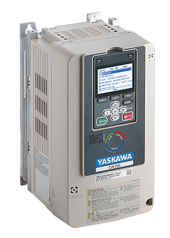
Описание модельного ряда
- Мощность 0,55 — 355 кВт
- Инвертор общего назначения высшей категории
- Векторное регулирование в замкнутом/разомкнутом контуре
- Перегрузочная способность 150% — 1 минута
- Глубина регулирования до 1:1500
- Управление при нулевой скорости без датчика
- Высокий пусковой крутящий момент
- Выходная частота до 590 Гц
- Встроенный программируемый контроллер
- Встроенный ЭМС фильтр класса C3
- Регулирование IM, iPM, sPM, SR двигателей
- Покрытие печатных плат
- Встроенный тормозной ключ (до 75 кВт)
- Встроенный RS-485
- Встроенные SIL3 Cat.3 Pl e for STO
- USB-mini порт для программирования
- Опциональная панель с Bluetooth
Схема маркировки
Модельный ряд
Интерфейсные карты
SI-ES3
Коммуникационная плата EtherCAT
SI-EP3
Коммуникационная плата ProfiNet
SI-P3
Коммуникационная плата ProfibusDP
SI-EN3
Коммуникационная плата EtherNet IP
SI-EN3D
Коммуникационная плата Dual Port EtherNet IP
SI-S3
Коммуникационная плата CANopen
SI-N3
Коммуникационная плата DeviceNET
SI-ET3
Коммуникационная плата Mechatrolink III
SI-T3
Коммуникационная плата Mechatrolink II
SI-C3
Коммуникационная плата CCLink
SI-EL3
Коммуникационная плата Powerlink
SI-EM3
Коммуникационная плата Modbus TCP
SI-EM3D
Коммуникационная плата Dual Port Modbus TCP
Карты обратной связи
PG-X3
Плата обратной связи, для подключения энкодера. Line driver.
Фазы А,B и Z, дифференц. вход (уровень RS-422), макс.частота 300кГц, питание
энкодера:+5.5 или +12В, имп. выход контроля: RS-422
PG-B3
Плата обратной связи, для подключения энкодера. Фазы А, B, Z
(комплем./открытый коллектор вход), макс.частота 50 кГц, питание энкодера:+12В, имп. выход контроля: откр. коллектор +24В
PG-E3
Плата обратной связи, для подключения энкодера ERN1387 (HEIDENHAIN), максимальная входная частота 20 кГц, питание энкодера 5 В
PG-F3
Плата обратной связи, для подключения энкодера с интерфейсами EnDat 2.1/01, EnDat 2.2/01, EnDat 2.2/22 (HEIDENHAIN) /HIPERFACE
(SICK STEGMANN) , Энкодеры HEIDENHAIN ECN1313, ECN113, ECN413, ECN1325, ECN125, ECN425 / SICK STEGMANN SRS50/60, SKS36, SFS60
PG-RT3
Плата обратной связи, для подключения резольвера. Рекомендуемый тип TS2640N321E64 Tamagawa Seiki Co., Ltd, 4096 имп/оборот
Тормозные резисторы
Входные и выходные фильтры и дроссели
Технические описания
Документация
Каталоги
Технические руководства
Карты обратной связи
Руководства по установке к картам обратной связи
Интерфейсные карты
Технические руководства к интерфейсным картам
Руководства по установке интерфейсных карт
Платы расширения
Руководства по установке плат расширения
Аксессуары для GA700
My Items
0,55 — 315,0 кВт
Высокопроизводительный инвертор общего назначения
Векторное регулирование в замкнутом/разомкнутом контуре
Перегрузочная способность 150% — 1 минута
Глубина регулирования до 1:1500
Управление при нулевой скорости без датчика
Высокий пусковой крутящий момент
Выходная частота до 590 Гц
Встроенный программируемый контроллер
Встроенный ЭМС фильтр класса C3
Регулирование IM, iPM, sPM, SR двигателей
Покрытие печатных плат
Встроенный тормозной ключ (до 75 кВт)
Встроенный RS-485
Встроенные SIL3 Cat.3 Pl e for STO
USB-mini порт для программирования
Опциональная панель с Bluetooth

Стандартные модели

Напряжение питания 3 фазы 400 В
|
GA700 |
Номинальная мощность |
Номинальный ток |
|---|---|---|
|
GA70C4002BBA |
0,55 кВт |
1,8 А |
|
GA70C4004BBA |
0,75 кВт |
3,4 А |
|
GA70C4005BBA |
1,5 кВт |
4,8 А |
|
GA70C4007BBA |
2,2 кВт |
5,5 А |
|
GA70C4009BBA |
3,0 кВт |
7,2 А |
|
GA70C4012BBA |
3,7 кВт |
9,2 А |
|
GA70C4018BBA |
5,5 кВт |
14,8 А |
|
GA70C4023BBA |
7,5 кВт |
18 А |
|
GA70C4031BBA |
11 кВт |
24 А |
|
GA70C4038BBA |
15 кВт |
31 А |
|
GA70C4044BBA |
18,5 кВт |
39 А |
|
GA70C4060BBA |
22 кВт |
45 А |
|
GA70C4075BBA |
30 кВт |
60 А |
|
GA70C4089BBA |
37 кВт |
75 А |
|
GA70C4103BBA |
45 кВт |
91 А |
|
GA70C4140BBA |
55 кВт |
112 А |
|
GA70C4168BBA |
75 кВт |
150 А |
|
GA70C4208BBA |
90 кВт |
180 А |
|
GA70C4250BBA |
110 кВт |
216 А |
|
GA70C4296BBA |
132 кВт |
260 А |
|
GA70C4371BBA |
160 кВт |
304 А |
|
GA70C4389BBA |
200 кВт |
371 А |
|
GA70C4453BBA |
220 кВт |
414 А |
|
GA70C4568BBA |
250 кВт |
453 А |
|
GA70C4675BBA |
315 кВт |
605 А |
Напряжение питания 3 фазы 200 В
|
GA700 |
Номинальная мощность |
Номинальный ток |
|---|---|---|
|
GA70C2004BBA |
0,55 кВт |
3,2 А |
|
GA70C2006BBA |
0,75 кВт |
5,0 А |
|
GA70C2010BBA |
1,5 кВт |
8,0 А |
|
GA70C2012BBA |
2,2 кВт |
11 А |
|
GA70C2018BBA |
3,0 кВт |
14 А |
|
GA70C2021BBA |
4,0 кВт |
17,5 А |
|
GA70C2030BBA |
5,5 кВт |
25 А |
|
GA70C2042BBA |
7,5 кВт |
33 А |
|
GA70C2056BBA |
11 кВт |
47 А |
|
GA70C2070BBA |
15 кВт |
60 А |
|
GA70C2082BBA |
18,5 кВт |
75 А |
|
GA70C2110BBA |
22 кВт |
88 А |
|
GA70C2138BBA |
30 кВт |
115 А |
|
GA70C2169BBA |
37 кВт |
145 А |
|
GA70C2211BBA |
45 кВт |
180 А |
|
GA70C2257BBA |
55 кВт |
215 А |
|
GA70C2313BBA |
75 кВт |
283 А |
|
GA70C2360BBA |
90 кВт |
346 А |
|
GA70C2415BBA |
110 кВт |
415 А |
Обозначение модели
Опциональные интерфейсные карты
Опциональные карты для подключения энкодеров
Подключение датчика обратной связи двигателя по положению к инвертору позволяет реализовать векторное регулирование в закрытом контуре.
Для подключения датчика обратной связи необходимо установить плату обратной связи.

Тормозные резисторы
Входные и выходные фильтры и дроссели
Технические руководства и каталоги
Каталоги
Технические руководства
Опциональные компоненты
|
TOEP C730600 94D |
английский |
JVOP-KPLCC04_ LCD Панели оператора для преобразователей GA700, GA500 и Bluetooth. Руководство по установке |
6,7 МБ |
|
TOEP C730600 97C |
английский |
JVOP-KPLCA04_ LCD Панели оператора для преобразователей GA700, GA500. Руководство по установке |
4,6 МБ |
|
TOEP C730600 74D |
английский |
JVOP-KPLEA04_ LED Панели оператора для преобразователей GA700, GA500. Руководство по установке |
4,3 МБ |
|
TOBP C730600 40A |
английский |
AO-A3 плата аналоговых выходов, руководство по установке |
1,7 МБ |
|
TOBP C730600 39A |
английский |
DI-A3 плата дискретных входов, руководство по установке |
1,8 МБ |
|
TOBP C730600 41A |
английский |
DO-A3 плата дискретных выходов, руководство по установке |
1,7 МБ |
|
TOBP C730600 53B |
английский |
PG-RT3 карта обратной связи, руководство по установке |
3,2 МБ |
|
TOBP C730600 36A |
английский |
PG-B3 карта обратной связи, руководство по установке |
1,8 МБ |
|
TOBP C730600 37A |
английский |
PG-X3 карта обратной связи, руководство по установке |
2,1 МБ |
|
TOBP C730600 38A |
английский |
AI-A3 плата аналоговых входов, руководство по установке |
1,8 МБ |
Интерфейсные карты
|
SIEP YAICOM 18C |
английский |
SI-EM3D Интерфейсная карта Dual Port Modbus TCP/IP, техническое руководство |
7,2 МБ |
|
TOEP YAICOM 18C |
английский |
SI-EM3D Интерфейсная карта Dual Port Modbus TCP/IP, руководство по установке |
6,3 МБ |
|
SIEP C730600 91C |
английский |
SI-EM3 Интерфейсная карта Modbus TCP/IP, техническое руководство |
6,6 МБ |
|
SIEP C730600 50A |
английский |
SI-T3 MECHATROLINK-II техническое руководство |
2,7 МБ |
|
TOBP C730600 85D |
английский |
SI-S3 CANopen техническое руководство |
6,3 МБ |
|
SIEP C730600 85C |
английский |
SI-S3 CANopen техническое руководство |
5,3 МБ |
|
TOBP C730600 86F |
английский |
SI-T3 MECHATROLINK-II руководство по установке |
1,6 МБ |
|
SIEP C730600 86E |
английский |
SI-T3 MECHATROLINK-II техническое руководство |
5,9 МБ |
|
TOBP C730600 50A |
английский |
SI-T3 MECHATROLINK-II руководство по установке |
5,7 МБ |
|
SIEP C730600 82D |
английский |
SI-P3 PROFIBUS-DP техническое руководство |
6,2 МБ |
|
TOBP C730600 84E |
английский |
SI-N3 DeviceNet руководство по установке |
7,6 МБ |
|
SIEP C730600 84E |
английский |
SI-N3 DeviceNet техническое руководство |
6,7 МБ |
|
TOBP C730600 82E |
английский |
SI-P3 PROFIBUS-DP руководство по установке |
7,4 МБ |
|
TOEPC71061687B |
английский |
SI-EL3, SI-EL3/V Интерфейсная карта Powerlink, руководство по установке |
5,7 МБ |
|
SIEP C730600 88E |
английский |
SI-ET3 Интерфейсная карта MECHATROLINK-III, техническое руководство |
6,0 МБ |
|
SIEP C730600 89E |
английский |
SI-EP3 Интерфейсная карта PROFINET, техническое руководство |
10,9 МБ |
|
TOBP C730600 89D |
английский |
SI-EP3 Интерфейсная карта PROFINET, руководство по установке |
7,2 МБ |
|
SIEPC71061686C |
английский |
SI-EL3, SI-EL3/V Интерфейсная карта Powerlink, техническое руководство |
7,0 МБ |
|
SIEP YAICOM 16A |
английский |
SI-EN3D Интерфейсная карта EtherNet/IP Dual port, техническое руководство |
8,0 МБ |
|
TOEP YAICOM 16A |
английский |
SI-EN3D Интерфейсная карта EtherNet/IP Dual port, руководство по установке |
7,1 МБ |
|
TOBP C730600 83D |
английский |
SI-C3 CC-Link руководство по установке |
6,8 МБ |
|
SIEP C730600 83D |
английский |
SI-C3 CC-Link техническое руководство |
5,6 МБ |
|
SIEP C730600 92D |
английский |
SI-EN3 Интерфейсная карта EtherNet/IP, техническое руководство |
6,7 МБ |
|
TOBP C730600 92D |
английский |
SI-EN3 Интерфейсная карта EtherNet/IP, руководство по установке |
8,4 МБ |
|
TOBP C730600 91D |
английский |
SI-EM3 Интерфейсная карта Modbus TCP/IP, руководство по установке |
8,3 МБ |
|
TOBP C730600 88E |
английский |
SI-ET3 Интерфейсная карта MECHATROLINK-III, руководство по установке |
6,5 МБ |
|
TOEPYEUOEC101 |
английский |
SI-ES3, SI-ES3/V Интерфейсная карта EtherCAT, руководство по установке |
5,7 МБ |
|
SIEPC71061699 |
английский |
SI-ES3, SI-ES3/V Интерфейсная карта EtherCAT, техническое руководство |
7,4 МБ |
Программное обеспечение
Для параметрирования инвертора GA700
Для программирования встроенного ПЛК инвертора GA700

DriveWizard Mobile
Загрузите бесплатное приложение DriveWizard, чтобы редактировать параметры и контролировать привод в режиме реального времени посредством подключения по Bluetooth или USB. Скопируйте параметры вашего привода в YASKAWA Drive Cloud, чтобы иметь доступ в любом месте в любое время.
- Manuals
- Brands
- YASKAWA Manuals
- Controller
- GA700
Manuals and User Guides for YASKAWA GA700. We have 3 YASKAWA GA700 manuals available for free PDF download: Technical Manual, Initial Steps
YASKAWA GA700 Technical Manual (1053 pages)
Brand: YASKAWA
|
Category: DC Drives
|
Size: 83.05 MB
Table of Contents
-
Preface and General Precautions
13
-
-
About Registered Trademarks
14
-
Using the Product Safely
15
-
Supplemental Safety Information
15
-
Warning Label Content and Location
17
-
-
-
Warranty and Exclusion of Liability
18
-
-
-
-
Model Number and Nameplate Check
21
-
How to Read Model Numbers
21
-
Features and Advantages of Control Methods
26
-
2 Mechanical & Electrical Installation
31
-
Installation Environment
35
-
Installation Position and Distance
36
-
-
Using the Hanging Brackets to Move the Drive
38
-
Instructions on Drive Suspension
38
-
-
Remove and Reattach the Keypad
44
-
Install the Keypad to a Control Panel or Another Device
45
-
Operate the Keypad Apart from the Drive
45
-
Connect the Keypad from a Remote Location
45
-
-
Removing/Reattaching Covers
50
-
Removing/Reattaching the Cover Using Procedure a
50
-
Removing/Reattaching the Cover Using Procedure B
51
-
-
Change the Drive Enclosure Type
55
-
Attach the Protective Cover (Procedure A)
55
-
Attach the Protective Cover (Procedure B)
56
-
Attach the Protective Cover (Procedure C)
58
-
Attach the Protective Cover (Procedure D)
61
-
Attach the Protective Cover (Procedure E)
63
-
Attach the Protective Cover (Procedure F)
65
-
-
Electrical Installation
73
-
Standard Connection Diagram
73
-
-
-
Motor and Main Circuit Connections
76
-
Configuration of Main Circuit Terminal Block
76
-
Main Circuit Terminal Functions
81
-
Main Circuit Terminal and Motor Wiring
94
-
Protection of Main Circuit Terminals
97
-
-
Main Circuit Terminal Block Wiring Procedure
98
-
Wiring the Main Circuit Terminal Block Using Procedure a
98
-
Wiring the Main Circuit Terminal Block Using Procedure B
101
-
-
Control Circuit Wiring
104
-
Control Circuit Connection Diagram
104
-
Control Circuit Terminal Block Functions
105
-
Control Circuit Terminal Configuration
108
-
Wiring the Control Circuit Terminal
110
-
Switches and Jumpers on the Terminal Board
112
-
-
Control I/O Connections
113
-
Set Sinking Mode/Sourcing Mode
114
-
Set Input Signals for MFAI Terminals A1 to A3
114
-
Set MFAI Terminal A3 to PTC Input
115
-
Set Output Signals for MFAO Terminals FM, am
115
-
Switch on Termination Resistor for Memobus/Modbus Communications
116
-
Connect the Drive to a PC
117
-
Braking Resistor Installation
119
-
Install a Braking Resistor: ERF-Type
119
-
Install a Braking Resistor Unit: LKEB-Type
119
-
Install a Braking Unit Connection: CDBR-Type
120
-
Connect Braking Units in Parallel
120
-
Dynamic Braking Option Overload Protection
121
-
-
Drive Wiring Protection
122
-
Install a Residual Current Monitoring/Detection (RCM/RCD)
122
-
Dynamic Braking Option, Motor Protection
123
-
Install an Electromagnetic Contactor (MC) at the Input Side of the Drive
123
-
Install a Thermal Overload Relay on the Drive Output
123
-
-
Improve the Power Factor
125
-
Connect an AC Reactor or a DC Reactor
125
-
-
Prevent Switching Surge
126
-
-
Connect a Noise Filter to the Input Side (Primary Side)
127
-
Connect a Noise Filter to the Output Side (Secondary Side)
127
-
-
Protect the Drive During Failures
129
-
Factory-Recommended Branch Circuit Protection
129
-
-
Motor Application Precautions
135
-
Precautions for Existing Standard Motors
135
-
Precautions for PM Motors
136
-
Precautions for Specialized Motors
136
-
Notes on the Power Transmission Mechanism
137
-
-
-
3 Startup Procedure and Test Run
139
-
Component Names and Functions
141
-
Indicator Leds and Drive Status
144
-
Keypad Mode and Menu Displays
145
-
-
Flowchart A: Connect and Run the Motor with Minimum Setting Changes
149
-
Sub-Chart A-1: Induction Motor Auto-Tuning and Test Run Procedure
150
-
Sub-Chart A-2: PM Motor Auto-Tuning and Test Run Procedure
150
-
Subchart A-3: EZ Open Loop Vector Control Test Run Procedure
152
-
-
Items to Check before Starting up the Drive
153
-
Check before Energizing the Drive
153
-
Check after Energizing the Drive
153
-
Make the Initial Settings
154
-
-
-
Show the Standard Monitor
156
-
Set the Monitors to Show as a Bar Graph
158
-
Show Monitors as Bar Graphs
159
-
Set the Monitors to Show as Analog Gauges
160
-
Display Monitors as an Analog Gauge
161
-
Set Monitoring Items to be Shown as a Trend Plot
162
-
Show Monitor Items as a Trend Plot
165
-
Change Parameter Settings
166
-
Examine User Custom Parameters
168
-
Save a Backup of Parameters
169
-
Write Backed-Up Parameters to the Drive
170
-
Verify Keypad Parameters and Drive Parameters
171
-
Delete Parameters Backed up to the Keypad
172
-
Check Modified Parameters
173
-
Restore Modified Parameters to Defaults
174
-
Auto-Tuning the Drive
176
-
Set the Keypad Language Display
179
-
Set the Date and Time
179
-
Set Parameters Using the Setup Wizard
181
-
Disable the Initial Setup Screen
183
-
Set Backlight to Automatically Turn off
186
-
Show Information about the Drive
188
-
Write Automatically Backed-Up Parameters to the Drive
189
-
Automatic Parameter Settings Optimized for Specific Applications
190
-
Automatic Parameter Settings Optimized for Specific Applications (Application Presets)
190
-
-
Auto-Tuning for Induction Motors
192
-
Auto-Tuning for PM Motors
193
-
Precautions before Auto-Tuning
199
-
-
-
Do a No-Load Test Run
202
-
Do an Actual-Load Test Run
203
-
Fine Tuning During Test Runs (Adjust the Control Function)
204
-
V/F Control and Closed Loop V/F Control
204
-
Open Loop Vector Control Method
205
-
Closed Loop Vector Control Method
208
-
Advanced Open Loop Vector Control Method
209
-
Fine-Tuning Open Loop Vector Control for PM Motors
211
-
Advanced Open Loop Vector Control Method for PM
212
-
Closed Loop Vector Control Method for PM
213
-
EZ Open Loop Vector Control Method
214
-
-
4 Standards Compliance
219
-
-
EU Declaration of Conformity
223
-
CE Low Voltage Directive Compliance
228
-
-
-
Wire the Main Circuit Terminal Block
256
-
Low Voltage Wiring for Control Circuit Terminals
276
-
Drive Motor Overload and Overheat Protection
276
-
China Rohs Compliance
282
-
Information on Hazardous Substances in this Product
282
-
-
-
Safe Disable Specifications
284
-
Using the Safe Disable Function
285
-
-
5 Network Communications
289
-
Field Bus Network Support
291
-
Memobus/Modbus Communications
292
-
Configure Master/Slave
292
-
Communication Specifications
292
-
Communication with the PLC
292
-
Memobus/Modbus Drive Operations
294
-
Communications Timing
294
-
Examples of Messages for Commands/Responses
297
-
Communications Data Table
303
-
-
-
Types of Faults, Minor Faults, Alarms, and Errors
330
-
List of Fault, Minor Fault, Alarm, and Error Codes
331
-
Parameter Setting Errors
374
-
Backup Function Operating Mode Display and Errors
386
-
Diagnosing and Resetting Faults
388
-
Fault and Power Loss Occur at the same Time
388
-
Fault Occurs Without Power Loss
388
-
-
Troubleshooting Without Fault Display
389
-
The Parameter Settings will Not Change
389
-
The Motor Does Not Rotate after Entering Run Command
389
-
The Motor Rotates in the Opposite Direction from the Run Command
390
-
The Motor Rotates in Only One Direction
391
-
The Correct Auto-Tuning Mode Is Not Available
391
-
The Motor Stalls During Acceleration or Accel/Decel Time Is too Long
392
-
The Motor Speed Is Not Stable When Using a PM Motor
393
-
There Is too Much Motor Oscillation and the Rotation Is Irregular
393
-
Deceleration Takes Longer than Expected When Dynamic Braking Is Enabled
394
-
The Load Falls When a Brake Is Applied
394
-
Residual Current Monitoring/Detection (RCM/RCD) Trips During Run
395
-
Motor Rotation Causes Unexpected Audible Noise from Connected Machinery
395
-
Motor Rotation Causes Oscillation or Hunting
395
-
The Starting Torque Is Not Sufficient
396
-
The Motor Rotates after the Drive Output Is Shut off
396
-
The Output Frequency Is Lower than the Frequency Reference
396
-
The Motor Is Making an Audible Noise
396
-
The Motor will Not Restart after a Loss of Power
396
-
-
7 Periodic Inspection and Maintenance
397
-
-
Recommended Daily Inspection
400
-
Recommended Periodic Inspection
400
-
-
Replace a Cooling Fan and Circulation Fan
405
-
Cooling Fans and Circulation Fans by Drive Model
405
-
Replace a Fan (Procedure A)
405
-
Replace a Fan (Procedure B)
407
-
Replace a Fan (Procedure C)
410
-
Replace a Fan (Procedure D)
412
-
Replace a Fan (Procedure E)
414
-
Replace Fans (Procedure F)
417
-
Replace Fans (Procedure G)
423
-
-
-
About the Control Circuit Terminal Block
431
-
-
Replace the Keypad Battery
437
-
-
Disposal Instructions
441
-
-
Model Specifications (200 V Class)
446
-
Model Specifications (400 V Class)
449
-
-
Carrier Frequency Settings and Rated Current Values
460
-
-
Drive Exterior and Mounting Dimensions
465
-
Drive Models and Exterior/Mounting Dimensions
465
-
Open Chassis Type (IP20)
466
-
Enclosed Wall-Mounted Type (UL Type 1)
476
-
-
Knock-Out Hole Dimensions (UL Type 1)
485
-
Models and Dimensions of Knock-Out Hole
485
-
-
Peripheral Devices and Options
490
-
-
How to Read the Parameter List
497
-
Icons and Terms that Identify Parameters and Control Modes
497
-
-
A: Initialization Parameters
500
-
-
B1: Operation Mode Selection
502
-
B2: DC Injection Braking and Short Circuit Braking
503
-
-
-
C1: Accel & Decel Time
513
-
C2: S-Curve Characteristics
514
-
C3: Slip Compensation
514
-
C4: Torque Compensation
515
-
C5: Automatic Speed Regulator Automatic Speed Regulator)
516
-
C6: Duty & Carrier Frequency
518
-
-
D: Reference Settings
519
-
D1: Frequency Reference
519
-
D4: Frequency Reference Hold and Up/Down 2 Function
522
-
D6: Field Weakening and Field Forcing
523
-
-
-
E1: V/F Pattern for Motor 1
525
-
E3: V/F Pattern for Motor 2
527
-
E4: Motor 2 Parameters
528
-
E5: PM Motor Settings
529
-
-
-
F1: PG Option Setup (Encoder)
531
-
F2: Analog Input Option
533
-
F3: Digital Input Option
534
-
F4: Analog Monitor Option
535
-
F5: Digital Output Option
536
-
F6: Communication Options
536
-
-
10.10 H: Terminal Functions
546
-
H5: Modbus Communication
564
-
H6: Pulse Train Input/Output
566
-
H7: Virtual Inputs/Outputs
566
-
10.11 L: Protection Functions
568
-
L2: Power Loss Ride through
569
-
L8: Hardware Protection
575
-
L9: Drive Protection 2
578
-
10.12 N: Special Adjustment
579
-
N1: Hunting Prevention
579
-
N2: Spdfeedbackdetectcontrol(Afr)Tun
580
-
N3: High Slip Braking (HSB)
580
-
N5: Feed Forward Control
582
-
N8: PM Motor Control Tuning
583
-
-
10.13 O: Keypad-Related Settings
586
-
O4: Maintenance Monitors
590
-
10.14 Q: Driveworksez Parameters
593
-
Q1-01 to Q8-40: Reserved for Driveworksez
593
-
-
R: DWEZ Connection 1-20
594
-
R1-01 to R1-40: Driveworksez Connection Parameters 1 to 20 (Upper / Lower)
594
-
-
10.16 T: Motor Tuning
595
-
T0: Tuning Mode Selection
595
-
T1: Inductionmotor Auto-Tuning
595
-
T2: PM Motor Auto-Tuning
596
-
T3: ASR and Inertia Tuning
597
-
-
U1: Operation Status Monitors
599
-
U4: Maintenance Monitors
605
-
U6: Operation Status Monitors
610
-
U8: Driveworksez Monitors
613
-
-
Parameters that Change from the Default Settings with A1-02
614
-
Parameters that Change from the Default Settings with A1-02 [Control Method Selection]
614
-
10.19 E3-01 [Motor 2 Control Mode] Dependent Parameters
620
-
Parameters Changed by E1-03 [V/F Pattern Selection]
621
-
10.21 Defaults by Drive Model and Duty Rating ND/HD
623
-
10.22 Parameters Changed by PM Motor Code Selection
647
-
Yaskawa SMRA Series SPM Motors
647
-
Yaskawa SSR1 Series IPM Motors (Derated Torque)
648
-
Yaskawa SST4 Series IPM Motors (Constant Torque)
660
-
-
-
-
A: Initialization Parameters
675
-
-
B1: Operation Mode Selection
697
-
B2: DC Injection Braking and Short Circuit Braking
710
-
-
-
C1: Accel & Decel Time
749
-
C2: S-Curve Characteristics
754
-
C3: Slip Compensation
755
-
C4: Torque Compensation
759
-
C5: Auto Speed Regulator (ASR)
762
-
C6: Duty & Carrier Frequency
771
-
-
-
D1: Frequency Reference
775
-
D4: Frequency Ref Up/Down & Hold
784
-
D6: Field Weakening /Forcing
795
-
-
-
E1: V/F Pattern for Motor 1
798
-
E3: V/F Pattern for Motor 2
809
-
E4: Motor 2 Parameters
811
-
E5: PM Motor Settings
814
-
-
-
F1: Encoder Option Setup
820
-
F2: Analog Input Option
827
-
F3: Digital Input Option
829
-
F4: Analog Monitor Option
834
-
F5: Digital Output Option
836
-
F6, F7: Communication Options
839
-
-
H: Terminal Functions
862
-
Multi-Function Digital Input Setting Values
866
-
H2: Multi-Function Digital Output
886
-
Multi-Function Analog Input Terminal Settings
918
-
H5: Memobus/Modbus Communication
927
-
H6: Pulse Train Input/Output
931
-
H7: Virtual Multi-Function I/O
934
-
L: Protection Functions
939
-
L2: Power Loss Ride through
945
-
L9: Drive Protection 2
986
-
11.10 N: Special Adjustment
987
-
N1: Hunting Prevention
987
-
N2: Auto Freq Regulator (AFR)
989
-
N3: High Slip Braking (HSB) and Overexcitation Braking
990
-
N4: Adv Open Loop Vector Tune
993
-
N5: Feed Forward Control
997
-
N8: PM Motor Control Tuning
1001
-
-
11.11 O: Keypad-Related Settings
1010
-
O1: Keypad Display Selection
1010
-
O2: Keypad Operation
1017
-
O4: Maintenance Mon Settings
1023
-
-
11.12 T: Auto-Tuning
1032
-
T0: Tuning Mode Selection
1032
-
T1: Inductionmotor Auto-Tuning
1032
-
T2: PM Motor Auto-Tuning
1035
-
T3: ASR and Inertia Tuning
1038
-
Advertisement
YASKAWA GA700 Technical Manual (936 pages)
High Performance Type; 200 V class: 0.4 to 110 kW; 400 V class: 0.4 to 355 kW
Brand: YASKAWA
|
Category: Controller
|
Size: 29.23 MB
Table of Contents
-
Preface and General Precautions
13
-
-
About Terms and Abbreviations in this Document
14
-
About Registered Trademarks
14
-
-
Using the Product Safely
15
-
Supplemental Safety Information
15
-
Warning Label Content and Locations
17
-
-
-
Warranty and Exclusion of Liability
18
-
I.3 Warranty Information
18
-
-
-
-
How to Read Model Numbers
21
-
2 Mechanical & Electrical Installation
25
-
Installation Environment
29
-
Installation Orientation and Spacing
30
-
-
Using the Hanging Brackets to Move the Drive
32
-
-
Remove or Install the Keypad
36
-
Install the Keypad on the Control Panel or Other Devices
37
-
Operate the Keypad Apart from the Drive
37
-
Install Keypad Apart from Drive
37
-
-
Removing/Reattaching the Cover
42
-
Removing/Reattaching the Cover Using Procedure a
42
-
-
Change the Drive’s Enclosure Type
44
-
Attach the Protective Cover (Procedure A)
44
-
-
Installation Procedure
46
-
Electrical Installation
50
-
Standard Connection Diagram
50
-
-
-
Configuration of Main Circuit Terminal Block
53
-
Main Circuit Terminal Functions
54
-
Main Circuit Wire Gauges and Tightening Torques
55
-
Main Circuit Terminal and Motor Wiring
64
-
Protection of Main Circuit Terminals
67
-
-
Wiring Procedure for the Main Circuit Terminal Block
68
-
Wiring the Main Circuit Terminal Block Using Procedure a
68
-
-
Control Circuit Wiring
71
-
Control Circuit Connection Diagram
71
-
Control Circuit Terminal Block Functions
72
-
Control Circuit Terminal Configuration
75
-
Wiring the Control Circuit Terminal
77
-
Switches and Jumpers on the Terminal Board
78
-
-
Control I/O Connections
80
-
Setting Sink Mode/Source Mode
81
-
Selection of Input Signals for Terminals A1 to A3 of Multi-Function Analog Input
81
-
Select Input Signal for Terminal A3 of Multi-Function Analog Input
82
-
Switch on Termination Resistor for Memobus/Modbus Communications
83
-
Install Braking Resistor
85
-
Installing a Braking Resistor: ERF Type
85
-
Installing a Braking Resistor Unit : LKEB Type
85
-
Installing a Braking Unit Connection: CDBR Type
86
-
Connect Braking Units in Parallel
86
-
Dynamic Braking Option Overload Protection
87
-
-
-
Installing a Ground Fault Circuit Interrupter
88
-
Dynamic Braking Option, Motor Protection
89
-
Installing an Electromagnetic Contactor (MC) at Input Side of Drive
89
-
Installing a Thermal Overload Relay on the Drive Output
89
-
-
Improving the Power Factor
91
-
Connecting an AC Reactor or DC Reactor
91
-
-
Preventing the Passage of Switching Surge
92
-
-
Connecting a Noise Filter to Input Side (Primary Side)
93
-
Connecting a Noise Filter to (Secondary Side)
93
-
-
Protect Drive at Failure
95
-
Factory Recommended Branch Circuit Protection
95
-
-
Motor Application Precautions
101
-
Use with Existing Standard Motors
101
-
Precautions Concerning Use of Specialized Motors
102
-
Notes on Power Transmission Mechanism
103
-
-
3 Initial Setup Trialrun
105
-
-
LED Indications of the Keypad
110
-
Keypad Modes and Menus
111
-
-
Flowchart a (Connect Motor and Run It with Minimal Setting Changes)
115
-
Sub-Chart A1 (Induction Motor Auto-Tuning and Test Run Procedure)
116
-
Sub-Chart A-2 (PM Motor Auto-Tuning and Test Run Procedure)
117
-
Subchart A-3 (EZ Open Loop Vector Control Test Run Procedure)
119
-
-
Items to Check before Starting up Drive
120
-
Check before Powering up Drive
120
-
Check after Powering up Drive
120
-
Perform the Initial Settings
121
-
-
-
Set Monitoring Favorites
124
-
Show Monitoring Favorites
124
-
Set Monitor to be Displayed as Bar Graph
125
-
Display Monitor as Bar Graph
126
-
Set Monitor to be Displayed as Analog Meter
127
-
Show Monitor as Analog Meter
128
-
Change Parameter Setting Values
129
-
Checking Commonly Used Parameters
130
-
Saving a Backup of Parameters
131
-
Writing Backed-Up Parameters to the Drive
132
-
Verify Keypad Parameters and Drive Parameters
133
-
Checking Modified Parameters
134
-
Restoring Default Settings for Modified Parameters
136
-
Display Fault History
137
-
Select Language of Display for Keypad
140
-
Set the Date and Time
141
-
Use Setup Wizard to Set Parameters
143
-
Disable the Start-Up Screen
144
-
Set Backlight to be Automatically off
148
-
Display the Drive Information
149
-
Automatic Parameter Settings Optimized for Specific Applications
151
-
-
Auto-Tuning for Induction Motors
153
-
Auto-Tuning for PM Motors
154
-
ASR and Inertia Tuning
157
-
Precautions to Note before Auto-Tuning
158
-
-
-
Perform a No-Load Test Run
161
-
Perform an Actual-Load Test Run
162
-
Fine Tuning During Test Runs (Adjustment of Control Functionality)
163
-
V/F Control and Closed Loop V/F Control
163
-
Open Loop Vector Control Method
164
-
Closed Loop Vector Control Method
167
-
Advanced Open Loop Vector Control Method
168
-
Open Loop Vector Control Method for PM
169
-
Advanced Open Loop Vector Control Method for PM
171
-
Closed Loop Vector Control Method for PM
171
-
EZ Open Loop Vector Control Method
172
-
-
-
4 Standards Compliance
177
-
-
CE Low Voltage Directive Compliance
180
-
-
-
Main Circuit Terminal Wiring
203
-
Low Voltage Wiring for Control Circuit Terminals
217
-
Drive Motor Overload and Overheat Protection
218
-
-
Using the Safe Disable Function
225
-
5 Network Communications
229
-
Field Bus Network Support
231
-
Memobus/Modbus Communications
232
-
Configure Master/Slave
232
-
Communication Specifications
232
-
Communication with PLC
232
-
Drive Operations by Memobus/Modbus
234
-
Communications Timing
234
-
Examples of Messages for Commands/Responses
237
-
Communications Data Table
240
-
-
-
Types of Faults, Minor Faults, Alarms, and Errors
266
-
List of Fault, Minor Fault, Alarm, and Error Codes
267
-
Parameter Setting Errors
309
-
Backup Function Operating Mode Display and Errors
320
-
Diagnosing and Resetting Faults
322
-
Fault Occurs Simultaneously with Power Loss
322
-
If the Drive Still Has Power after a Fault Occurs
322
-
-
Troubleshooting Without Fault Display
323
-
Cannot Change Parameter Settings
323
-
Motor Does Not Rotate after Entering Run Command
323
-
Motor Rotates in the Opposite Direction from the Run Command
325
-
Motor Rotates in One Direction Only
325
-
Drive Does Not Allow Selection of the Desired Auto-Tuning Mode
326
-
Motor Stalls During Acceleration or Accel/Decel Time Is too Long
326
-
Drive Frequency Reference Differs from the Controller Frequency Reference
327
-
Unstable Motor Speed When Using PM Motor
327
-
Excessive Motor Oscillation and Erratic Rotation
328
-
Deceleration Takes Longer than Expected with Dynamic Braking Enabled
328
-
Load Falls When Brake Is Applied
328
-
Noise from Drive or Motor Cables When the Drive Is Powered on
329
-
Earth Leakage Circuit Breaker (ELCB) Trips During Run
329
-
Unexpected Noise from Connected Machinery Occurs When Motor Rotates
329
-
Oscillation or Hunting Occurs When Motor Rotates
329
-
Insufficient Starting Torque
330
-
Motor Rotates after the Drive Output Is Shut off
330
-
Output Frequency Is Not as High as Frequency Reference
330
-
Motor Does Not Restart after Power Loss
331
-
-
7 Periodic Inspection & Maintenance
333
-
-
Recommended Daily Inspection
336
-
Recommended Periodic Inspection
336
-
-
Replace a Cooling Fan and Circulation Fan
342
-
Number of Cooling Fans and Circulation Fans Used
342
-
Replace a Fan (Procedure A)
342
-
Replace a Fan (Procedure B)
344
-
Replace a Fan (Procedure C)
346
-
-
-
About the Control Circuit Terminal Block
349
-
-
Replace the Keypad Battery
353
-
-
Disposal Instructions
359
-
-
Heavy Duty and Normal Duty Ratings
363
-
Model Specifications (200 V Class)
364
-
Model Specifications (400 V Class)
367
-
-
Carrier Frequency Settings and Rated Current Value
375
-
-
Drive Exterior and Mounting Dimensions
379
-
Open Chassis Type (IP20)
379
-
Enclosed Wall-Mounted Type (UL Type 1)
381
-
-
Knock-Out Hole Dimensions (UL Type 1)
385
-
Peripheral Devices and Options
386
-
-
How to Read the Parameter List
393
-
Icons and Terms Used to Represent Control Modes
393
-
-
A: Initialization Parameters
398
-
-
B1: Operation Mode Selection
400
-
B2: DC Injection Braking and Short Circuit Braking
401
-
-
-
C1: Accel and Decel Times
411
-
C2: S-Curve Characteristics
411
-
C3: Slip Compensation
412
-
C4: Torque Compensation
413
-
C5: Automatic Speed Regulator Automatic Speed Regulator)
414
-
C6: Carrier Frequency
416
-
-
D: Reference Settings
417
-
D1: Frequency Reference
417
-
D4: Frequency Reference Hold and Up/Down 2 Function
420
-
D6: Field Weak & Field Force
421
-
-
-
E1: V/F Pattern for Motor 1
423
-
E3: V/F Pattern for Motor 2
425
-
E4: Motor 2 Parameters
426
-
E5: PM Motor Settings
427
-
-
-
F1: PG Speed Control Card (Encoder)
429
-
F2: Analog Input Option
431
-
F3: Digital Input Option
432
-
F4: Analog Monitor Option
433
-
F5: Digital Output Option
434
-
F6: Communication Option and Ethernet Option
435
-
F7: Communication Option and Ethernet Option
439
-
-
10.10 H: Terminal Functions
444
-
H1: Multi-Function Digital Inputs
444
-
H2: Multi-Function Digital Output
450
-
H3: Multi-Function Analog Inputs
458
-
H5: Memobus/Modbus Communication
462
-
H6: Pulse Train Input/Output
463
-
H7: Virtual Multi-Function I/O
464
-
-
10.11 L: Protection Function
466
-
L2: Momentary Power Loss Ride-Thru
467
-
L8: Hardware Protection
473
-
L9: Drive Protection 2
476
-
10.12 N: Special Adjustment
477
-
N1: Hunting Prevention
477
-
N2: Spdfeedbackdetectcontrol(Afr)Tun
478
-
N3: High Slip Braking (HSB)
478
-
N5: Feed Forward Control
480
-
N8: PM Motor Control Tuning
481
-
-
10.13 O: Keypad-Related Settings
484
-
O1: Keypad Display Selection
484
-
O4: Maintenance Mon Settings
487
-
-
10.14 Q: Driveworksez Parameters
490
-
Q1-01 to Q8-40: Reserved for Driveworksez
490
-
-
R: DWEZ Connection 1-20
491
-
R1-01 to R1-40: Driveworksez Connection Parameters 1 to 20 (Upper / Lower)
491
-
-
10.16 T: Motor Tuning
492
-
T0: Tuning Mode Selection
492
-
T1: Induction Motor Auto-Tuning
492
-
T2: PM Motor Auto-Tuning
493
-
T3: ASR and Inertia Tuning
494
-
-
-
U1: Operation Status Monitor
496
-
U4: Maintenance Monitors
502
-
U6: Operation Status Monitors
507
-
U8: Driveworksez Monitors
510
-
-
10.18 A1-02 [Motor 1 Control Mode] Dependent Parameters
511
-
10.19 E3-01 [Motor 2 Control Mode] Dependent Parameters
517
-
Parameters Changed by E1-03 [V/F Pattern Selection]
518
-
10.21 Defaults by Drive Model and Duty Rating ND/HD
520
-
10.22 Parameters Changed by PM Motor Code Selection
543
-
Yaskawa SMRA Series SPM Motors
543
-
Yaskawa SSR1 Series IPM Motors (Derated Torque)
544
-
Yaskawa SST4 Series IPM Motors (Constant Torque)
556
-
-
-
A: Initialization Parameters
571
-
-
B1: Operation Mode Selection
592
-
B2: DC Injection Braking and Short Circuit Braking
604
-
-
-
C1: Accel and Decel Times
643
-
C2: S-Curve Characteristics
647
-
C3: Slip Compensation
648
-
C4: Torque Compensation
652
-
C5: Automatic Speed Regulator (ASR)
654
-
C6: Carrier Frequency
664
-
-
D: Reference Settings
668
-
D1: Frequency Reference
668
-
D4: Frequency Reference Hold and Up/Down 2 Function
677
-
D6: Field Weakening and Field Forcing
687
-
-
-
E1: V/F Pattern for Motor 1
689
-
E3: V/F Pattern for Motor 2
700
-
E4: Motor 2 Parameters
702
-
E5: PM Motor Settings
705
-
-
-
F1: PG Speed Control Card Encoder
711
-
F2: Analog Input Option
718
-
F3: Digital Input Option
720
-
F4: Analog Monitor Option
724
-
F5: Digital Output Option
727
-
F6, F7: Communication Options
730
-
-
H: Terminal Functions
752
-
H1: Multi-Function Digital Input
752
-
Multi-Function Digital Input Setting Values
756
-
H2: Multi-Function Digital Output
776
-
H3: Multi-Function Analog in
800
-
Multi-Function Analog Input Terminal Settings
807
-
H5: Memobus/Modbus Communication
816
-
H6: Pulse Train Input/Output
820
-
H7: Virtual Multi-Function I/O
823
-
-
L: Protection Function
827
-
L2: Momentary Power Loss Ride-Thru
833
-
L6: Detection of Overtorque/Undertorque
856
-
L9: Drive Protection 2
873
-
11.10 N: Special Adjustment
874
-
N1: Hunting Prevention Function
874
-
N2: Speed Feedback Detection Control (AFR) Tuning
876
-
N3: High Slip Braking (HSB) and Overexcitation Braking
877
-
N5: Feed Forward Control
884
-
N8: PM Motor Control Tuning
888
-
-
11.11 O: Keypad-Related Settings
897
-
O1: Keypad Display Selection
897
-
O4: Maintenance Mon Settings
907
-
-
-
T0: Tuning Mode Selection
916
-
T1: Inductionmotor Auto-Tuning
916
-
T2: PM Motor Auto-Tuning
919
-
T3: ASR and Inertia Tuning
922
-

YASKAWA GA700 Initial Steps (33 pages)
High Performance Type
Brand: YASKAWA
|
Category: Controller
|
Size: 7.05 MB
Table of Contents
-
Qualifications for the Intended User
2
-
Explanation of Signal Words
2
-
General Safety Instructions
2
-
Warranty and Exclusion of Liability
4
-
Keypad Mode and Menu Displays
8
-
Mechanical Installation
12
-
Installation Position and Distance
12
-
Single Drive Installation
12
-
Installation Environment
13
-
Remove the Front Cover
14
-
Remove the Terminal Cover
15
-
Electrical Installation
18
-
Standard Connection Diagram
18
-
Change Parameter Settings
24
Advertisement
Advertisement
Related Products
-
YASKAWA GPD515C
-
YASKAWA GA500 series
-
YASKAWA GA800 Series
-
YASKAWA GA800 600 V Drive
-
YASKAWA MEMOCON GL120
-
YASKAWA MEMOCON GL130
-
YASKAWA GA50U Series
-
YASKAWA GA50U4004ABA
-
YASKAWA GA700 GA700 Series
-
YASKAWA GA70C4296BBA
YASKAWA Categories
Controller
DC Drives
Servo Drives
Robotics
Control Unit
More YASKAWA Manuals
-
Contents
-
Table of Contents
-
Troubleshooting
-
Bookmarks
Quick Links
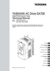
YASKAWA AC Drive GA700
High Performance Type
Technical Manual
Type:
CIPR-GA70Axxxxxxxx
Models: 200 V class: 0.4 to 110 kW
400 V class: 0.4 to 355 kW
To properly use the product, read this manual thoroughly and retain for easy
reference, inspection, and maintenance. Ensure the end user receives this
manual.
MANUAL NO. SIEP C710617 01B
1
Receiving
Mechanical & Electrical
2
Installation
3
Initial SetUp TrialRUN
4
Standards Compliance
5
Network Communications
6
Troubleshooting
Periodic Inspection &
7
Maintenance
8
Disposal
9
Specifications
10
Parameter List
11
Parameter Details
Troubleshooting
Summary of Contents for YASKAWA GA700
YASKAWA GA700: List of Available Documents
Note for Owners:
Guidesimo.com webproject is not a service center of YASKAWA trademark and does not carries out works for diagnosis and repair of faulty YASKAWA GA700 equipment. For quality services, please contact an official service center of YASKAWA company. On our website you can read and download documentation for your YASKAWA GA700 device for free and familiarize yourself with the technical specifications of device.
More Controller Devices:
-
SeaLevel Relio R2 SYNC
1 © Sealevel Systems, Inc. RELIO R2 SYNC Manual | SL9255 10/2021 Relio R2 SYNC User Manual | RELIO R2 SYNC …
Relio R2 SYNC Controller, 32
-
Franke AQUA802
Installation and operating instructions Istruzioni per il montaggio e l’usoNotice de montage et de mise en service Montage- en bedrijfsinstructiesInstrucciones de montaje y uso Istruzioni per il montaggio e l’usoZMI_001_2000100418-AQUA802_#SALL_#AQU_#V2.fm / 10.08.20EA-Nr.: 7612982130793FAR-Best.-Nr.: 2000100418AQUA802EA-Nr.: 7612982130809FAR-Best.-Nr.: 2000100419AQUA803DEENFRESITNLPL …
AQUA802 Controller, 44
-
Siemens SIMATIC
___________________ ___________________ ___________________ ___________________ ___________________ SIMATIC Industrial PC Panel Drivers and Tools V1.3 PDT IFP Monitor Standard Operating Manual 10/2017 A5E41104536-AB Preface Panel Drivers and Tools software 1 IPC Configuration Center 2 Software description 3 Technical support A …
SIMATIC Industrial PC, 26
-
Fisher FIELDVUE DVC6200
www.Fisher.comZero Point CalibrationHART® Communicating Fisher™ FIELDVUE™DVC6200 Digital Valve ControllersThe Zero Point Calibration procedure allows you replace an existing DVC6200 digital valve controller withoutperforming a travel calibration. This procedure can be used when a situation occurs that requires the partial orcomplete replacement of a digital valve controller when part of a val …
FIELDVUE DVC6200 Controller, 5
Recommended Documentation:
Download Technical manual of YASKAWA GA700 Controller, DC Drives for Free or View it Online on All-Guides.com.

1

2

3

4

5

6

7

8

9

10

11

12

13

14

15

16

17

18

19

20

21

22

23

24

25

26

27

28

29

30

31

32

33

34

35

36

37

38

39

40

41

42

43

44

45

46

47

48

49

50

51

52

53

54

55

56

57

58

59

60

61

62

63

64

65

66

67

68

69

70

71

72

73

74

75

76

77

78

79

80

81

82

83

84

85

86

87

88

89

90

91

92

93

94

95

96

97

98

99

100

101

102

103

104

105

106

107

108

109

110

111

112

113

114

115

116

117

118

119

120

121

122

123

124

125

126

127

128

129

130

131

132

133

134

135

136

137

138

139

140

141

142

143

144

145

146

147

148

149

150

151

152

153

154

155

156

157

158

159

160

161

162

163

164

165

166

167

168

169

170

171

172

173

174

175

176

177

178

179

180

181

182

183

184

185

186

187

188

189

190

191

192

193

194

195

196

197

198

199

200

201

202

203

204

205

206

207

208

209

210

211

212

213

214

215

216

217

218

219

220

221

222

223

224

225

226

227

228

229

230

231

232

233

234

235

236

237

238

239

240

241

242

243

244

245

246

247

248

249

250

251

252

253

254

255

256

257

258

259

260

261

262

263

264

265

266

267

268

269

270

271

272

273

274

275

276

277

278

279

280

281

282

283

284

285

286

287

288

289

290

291

292

293

294

295

296

297

298

299

300

301

302

303

304

305

306

307

308

309

310

311

312

313

314

315

316

317

318

319

320

321

322

323

324

325

326

327

328

329

330

331

332

333

334

335

336

337

338

339

340

341

342

343

344

345

346

347

348

349

350

351

352

353

354

355

356

357

358

359

360

361

362

363

364

365

366

367

368

369

370

371

372

373

374

375

376

377

378

379

380

381

382

383

384

385

386

387

388

389

390

391

392

393

394

395

396

397

398

399

400

401

402

403

404

405

406

407

408

409

410

411

412

413

414

415

416

417

418

419

420

421

422

423

424

425

426

427

428

429

430

431

432

433

434

435

436

437

438

439

440

441

442

443

444

445

446

447

448

449

450

451

452

453

454

455

456

457

458

459

460

461

462

463

464

465

466

467

468

469

470

471

472

473

474

475

476

477

478

479

480

481

482

483

484

485

486

487

488

489

490

491

492

493

494

495

496

497

498

499

500

501

502

503

504

505

506

507

508

509

510

511

512

513

514

515

516

517

518

519

520

521

522

523

524

525

526

527

528

529

530

531

532

533

534

535

536

537

538

539

540

541

542

543

544

545

546

547

548

549

550

551

552

553

554

555

556

557

558

559

560

561

562

563

564

565

566

567

568

569

570

571

572

573

574

575

576

577

578

579

580

581

582

583

584

585

586

587

588

589

590

591

592

593

594

595

596

597

598

599

600

601

602

603

604

605

606

607

608

609

610

611

612

613

614

615

616

617

618

619

620

621

622

623

624

625

626

627

628

629

630

631

632

633

634

635

636

637

638

639

640

641

642

643

644

645

646

647

648

649

650

651

652

653

654

655

656

657

658

659

660

661

662

663

664

665

666

667

668

669

670

671

672

673

674

675

676

677

678

679

680

681

682

683

684

685

686

687

688

689

690

691

692

693

694

695

696

697

698

699

700

701

702

703

704

705

706

707

708

709

710

711

712

713

714

715

716

717

718

719

720

721

722

723

724

725

726

727

728

729

730

731

732

733

734

735

736

737

738

739

740

741

742

743

744

745

746

747

748

749

750

751

752

753

754

755

756

757

758

759

760

761

762

763

764

765

766

767

768

769

770

771

772

773

774

775

776

777

778

779

780

781

782

783

784

785

786

787

788

789

790

791

792

793

794

795

796

797

798

799

800

801

802

803

804

805

806

807

808

809

810

811

812

813

814

815

816

817

818

819

820

821

822

823

824

825

826

827

828

829

830

831

832

833

834

835

836

837

838

839

840

841

842

843

844

845

846

847

848

849

850

851

852

853

854

855

856

857

858

859

860

861

862

863

864

865

866

867

868

869

870

871

872

873

874

875

876

877

878

879

880

881

882

883

884

885

886

887

888

889

890

891

892

893

894

895

896

897

898

899

900

901

902

903

904

905

906

907

908

909

910

911

912

913

914

915

916

917

918

919

920

921

922

923

924

925

926

927

928

929

930

931

932

933

934

935

936

Receiving
1
Mechanical & Electrical
Installation
2
Initial SetUp TrialRUN
3
Standards Compliance
4
Network Communications
5
Troubleshooting
6
Periodic Inspection &
Maintenance
7
Disposal
8
Specifications
9
Parameter List
10
Parameter Details
11
MANUAL NO. SIEP C710617 01B
YASKAWA AC Drive GA700
High Performance Type
Technical Manual
Type: CIPR-GA70Axxxxxxxx
Models: 200 V class: 0.4 to 110 kW
400 V class: 0.4 to 355 kW
To properly use the product, read this manual thoroughly and retain for easy
reference, inspection, and maintenance. Ensure the end user receives this
manual.
YASKAWA Manuals and Guides:
The main types of YASKAWA GA700 instructions: user guide — rules of useing and characteristics, service manual — repair, diagnostics, maintenance, operation manual — description of the main functions of YASKAWA GA700 equipment, etc.
Most of the instructions, that you can see on the site are uploaded by our users. If you have available a manual or document for YASKAWA GA700, which is currently not on the site or present in a different language version, we ask you to upload your document on website, using the «uploading form» available to all registered users.
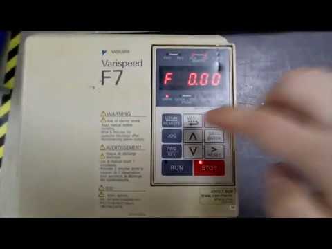
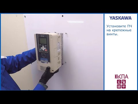
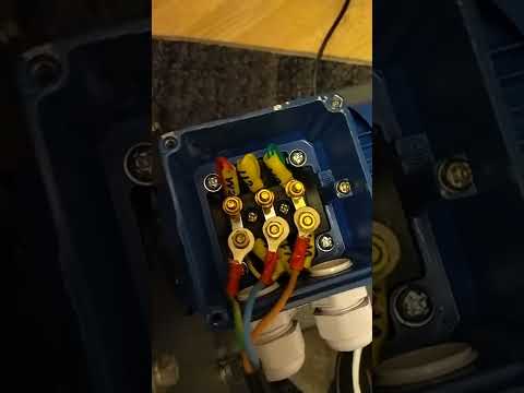
Установка преобразователя частоты YASKAWA GA700 7,5 кВтПодробнее
Как повторно инициализировать и восстановить заводские настройки преобразователя частоты Yaskawa GA800Подробнее

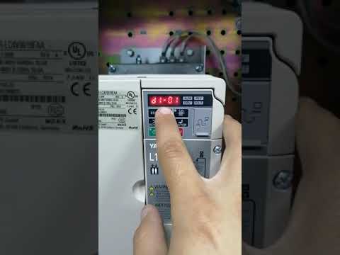
Работа с преобразователем частоты YASKAWAПодробнее
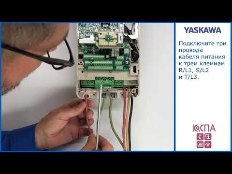
Подключение ПЧ GA700 к двигателю и питающей сетиПодробнее
Настройка преобразователя частоты серия ZNПодробнее
Как подключать и настраивать частотный преобразователь. 2 Часть.Подробнее

Станция УЛ ПУ 3, настройка ЧП YASKAWAПодробнее
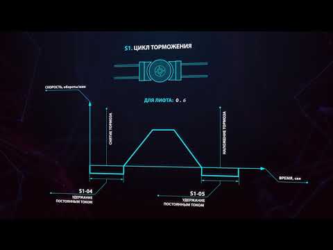
Частотный преобразователь GA700, компенсация вибрацииПодробнее
Инструкция по настройке частотного преобразователя Yaskawa L1000VПодробнее
Частотный преобразователь как правильно подключить частотникПодробнее
Настройка частотного преобразователя серии ZVПодробнее
Подключение частотного преобразователя к токарному станку ТВ-4Подробнее
Преобразователь частоты Omron 3G3JX. Настраиваем и экспериментируем.Подробнее
Настройка преобразователя частоты CHINT NVF2GПодробнее

Как настроить параметры управления частотного преобразователяПодробнее
Быстрая настройка и подключение частотного преобразователя АТ-1Подробнее
Обзор возможностей и быстрый запуск YASKAWA GA500Подробнее
Настройка китайского инвертера (преобразователя частот) для асинхронного двигателяПодробнее
AC4139 Преобразователь частоты YASKAWA CIMR-F7B47P5 7.5 кВтПодробнее