
- Все
- Инструкции по монтажу
- Инструкции по эксплуатации
- Инструкции сервис обслуживания
- Программное обеспечение
- Каталоги
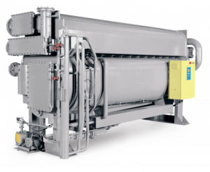
АБХМ нагрев паром
Абсорбционные чиллеры LG нагрев паром АБХМ нагрев паром
АБХМ прямого нагрева
Абсорбционные чиллеры LG прямого нагрева АБХМ прямого нагрева
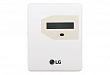
Блок управления испарителем
Блок управления испарителем LG PAHCMR000 / PAHCMS000
Товары снятые с производства
Блок управления испарителем LG PRCKA1
Модули учета потребляемой энергии
Блок учёта потребляемой энергии LG PPWRDB000
Принадлежности блоков КАНАЛЬНОГО типа
Зональный контроллер LG ABZCA
Доп. оборудование
Кабель группового управления LG PZCWRCG3
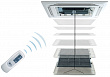
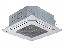
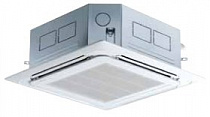
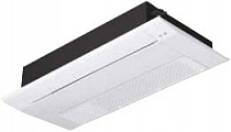
Кассетный тип
Кассетный блок LG High Inverter R410a CT18 / UU18W
Модули интеграции
Модуль внешнего сигнала LG PMNFP14A1
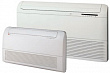
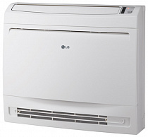
Напольно-потолочный (1Ø)
Напольно-потолочный блок LG Smart Inverter R410a CV09
Наружные блоки Multi F [R410a]
Наружный блок LG Multi F MU2M15
Наружные блоки Multi FDX [R410a]
Наружный блок LG Multi FDX FM40AH
Настенный тип
Настенный блок LG High Inverter R410a Standard UJ30 / UU30W
Принадлежности для наружных блоков
Переключатель тепло-холод LG PRDSBM
Индивидуальное управление
Проводной пульт дистанционного управления LG PREMTBB01 (черный)
Центральное управление
Центральный контроллер LG PQCSZ250S0
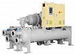
Центробежные
Центробежные чиллеры LG
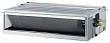
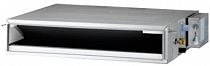
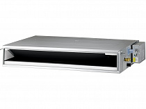
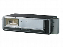
Высоко / средненапорный Канальный тип
Высоко / средненапорный канальный блок LG ARNU07GM1A4
Датчики
Датчик CO2 LG PES-C0RV0
АБХМ нагрев водой
Абсорбционные чиллеры LG нагрев водой АБХМ нагрев водой
Принадлежности блоков КАССЕТНОГО типа
Механизм автоматической панели LG PTEGM0
Потолочный (1Ø)
Потолочный блок LG Smart Inverter R410a CV24
Потолочный (3Ø)
Потолочный блок LG Smart Inverter R410a UV36W (3Ø)
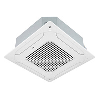
Четырехпоточный (1Ø)
Кассетный блок LG Smart Inverter R410a CT09 (1Ø)
Высоконапорный тип
Высоконапорный канальный блок LG Smart Inverter R410a UB70W

ARTCOOL Mirror Настенный тип
Настенный блок LG Artcool Mirror ARNU05GSJR4
Настенный блок LG Artcool Mirror ARNU07GSJR4
Настенный блок LG Artcool Mirror ARNU09GSJR4
Настенный блок LG Artcool Mirror ARNU12GSJR4
Настенный блок LG Artcool Mirror ARNU15GSJR4
Настенный блок LG Artcool Mirror ARNU18GSKR4
Настенный блок LG Artcool Mirror ARNU24GSKR4
MULTI V 5 Наружные блоки VRF воздушного охлаждения (тепловой насос/рекуперация)
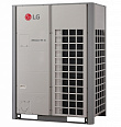
Наружный блок LG MULTI V 5 ARUM080LTE5
Наружный блок LG MULTI V 5 ARUM100LTE5
Наружный блок LG MULTI V 5 ARUM120LTE5
Наружный блок LG MULTI V 5 ARUM140LTE5
Наружный блок LG MULTI V 5 ARUM160LTE5
Наружный блок LG MULTI V 5 ARUM180LTE5
Наружный блок LG MULTI V 5 ARUM200LTE5
Наружный блок LG MULTI V 5 ARUM220LTE5
Наружный блок LG MULTI V 5 ARUM240LTE5
Наружный блок LG MULTI V 5 ARUM260LTE5
Наружный блок LG MULTI V 5 ARUM280LTE5
Наружный блок LG MULTI V 5 ARUM300LTE5
Наружный блок LG MULTI V 5 ARUM320LTE5
Наружный блок LG MULTI V 5 ARUM340LTE5
Наружный блок LG MULTI V 5 ARUM360LTE5
Наружный блок LG MULTI V 5 ARUM380LTE5
Наружный блок LG MULTI V 5 ARUM400LTE5
Наружный блок LG MULTI V 5 ARUM420LTE5
Наружный блок LG MULTI V 5 ARUM440LTE5
Наружный блок LG MULTI V 5 ARUM460LTE5
Наружный блок LG MULTI V 5 ARUM480LTE5
Наружный блок LG MULTI V 5 ARUM500LTE5
Наружный блок LG MULTI V 5 ARUM520LTE5
Наружный блок LG MULTI V 5 ARUM540LTE5
Наружный блок LG MULTI V 5 ARUM560LTE5
Наружный блок LG MULTI V 5 ARUM580LTE5
Наружный блок LG MULTI V 5 ARUM600LTE5
Наружный блок LG MULTI V 5 ARUM620LTE5
Наружный блок LG MULTI V 5 ARUM640LTE5
Наружный блок LG MULTI V 5 ARUM660LTE5
Наружный блок LG MULTI V 5 ARUM680LTE5
Наружный блок LG MULTI V 5 ARUM700LTE5
Наружный блок LG MULTI V 5 ARUM720LTE5
Наружный блок LG MULTI V 5 ARUM740LTE5
Наружный блок LG MULTI V 5 ARUM760LTE5
Наружный блок LG MULTI V 5 ARUM780LTE5
Наружный блок LG MULTI V 5 ARUM800LTE5
Наружный блок LG MULTI V 5 ARUM820LTE5
Наружный блок LG MULTI V 5 ARUM840LTE5
Наружный блок LG MULTI V 5 ARUM860LTE5
Наружный блок LG MULTI V 5 ARUM880LTE5
Наружный блок LG MULTI V 5 ARUM900LTE5
Наружный блок LG MULTI V 5 ARUM920LTE5
Наружный блок LG MULTI V 5 ARUM940LTE5
Наружный блок LG MULTI V 5 ARUM960LTE5
Низконапорный тип
Низконапорный канальный блок LG Smart Inverter R410a CB09L
Низконапорный канальный блок LG Smart Inverter R410a CB12L
Низконапорный канальный блок LG Smart Inverter R410a CB18L
Низконапорный канальный блок LG Smart Inverter R410a CB24L
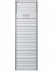
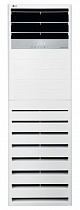
Колонный (1Ø)
Колонный блок LG Smart Inverter R410a UP48
4-поточные
4-поточный кассетный блок LG High Inverter R410a UT12
4-поточный кассетный блок LG High Inverter R410a UT18
4-поточный кассетный блок LG High Inverter R410a UT24
4-поточный кассетный блок LG High Inverter R410a UT30
4-поточный кассетный блок LG High Inverter R410aUT36
4-поточный кассетный блок LG High Inverter R410a UT48
4-поточный кассетный блок LG High Inverter R410a UT60
Напольнопотолочные
Напольно-потолочный блок LG High Inverter R410a UV12
Напольно-потолочный блок LG High Inverter R410a UV18
Напольно-потолочный блок LG High Inverter R410aUV24
Напольно-потолочный блок LG High Inverter R410a UV30
Standard
Настенный блок LG Standard PM05SP
Настенный блок LG Standard PM07SP
Настенный блок LG Standard PM09SP
Настенный блок LG Standard PM12SP
Настенный блок LG Standard PM15SP
Настенный блок LG Standard PM18SP
Настенный блок LG Standard PM24SP
Серия V
Винтовые чиллеры LG воздушного охлаждения MCAW008AA11
Винтовые чиллеры LG воздушного охлаждения MCAW010AA11
Винтовые чиллеры LG воздушного охлаждения MCAW012AA11
Винтовые чиллеры LG воздушного охлаждения MCAW014AA11
Винтовые чиллеры LG воздушного охлаждения MCAW016AA11
Однопоточный
Кассетный однопоточный блок LG MT09R
Кассетный однопоточный блок LG MT11R
Напольно-потолочный
Напольно-потолочный блок LG CV12
MULTI V WATER 4 Наружные блоки VRF водяного охлаждения (тепловой насос)
Наружный блок LG Multi V Water IV ARWN080LAS4
Наружный блок LG Multi V Water IV ARWN100LAS4
Наружный блок LG Multi V Water IV ARWN140LAS4
Наружный блок LG Multi V Water IV ARWN200LAS4
Наружный блок LG Multi V Water IV ARWN220LAS4
Наружный блок LG Multi V Water IV ARWN240LAS4
Наружный блок LG Multi V Water IV ARWN280LAS4
Наружный блок LG Multi V Water IV ARWN300LAS4
Наружный блок LG Multi V Water IV ARWN340LAS4
Наружный блок LG Multi V Water IV ARWN400LAS4
Наружный блок LG Multi V Water IV ARWN420LAS4
Наружный блок LG Multi V Water IV ARWN440LAS4
Наружный блок LG Multi V Water IV ARWN480LAS4
Наружный блок LG Multi V Water IV ARWN500LAS4
Наружный блок LG Multi V Water IV ARWN540LAS4
Наружный блок LG Multi V Water IV ARWN600LAS4
Наружный блок LG Multi V Water IV ARWN620LAS4
Наружный блок LG Multi V Water IV ARWN640LAS4
Наружный блок LG Multi V Water IV ARWN680LAS4
Наружный блок LG Multi V Water IV ARWN700LAS4
Наружный блок LG Multi V Water IV ARWN740LAS4
Наружный блок LG Multi V Water IV ARWN800LAS4
Воздушного охлаждения (1Ø)
Наружный блок LG Multi V S ARUN040GSS0
Наружный блок LG Multi V S ARUN050GSS0
Наружный блок LG Multi V S ARUN050GSL0
Наружный блок LG Multi V S ARUN060GSS0
ЭРВ
Электронный Расширительный Вентиль LG PRLK048A0
Электронный Расширительный Вентиль LG PRLK096A0
ARTCOOL Gallery
Кондиционер LG ARTCOOL Gallery A09FT
Кондиционер LG ARTCOOL Gallery A12FT
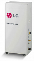
Hydro kit средней температуры
Средненапорный модуль LG Hydro Kit ARNH04GK2A4
Средненапорный модуль LG Hydro Kit ARNH10GK2A4
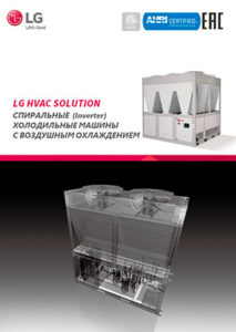
Спиральные
Спиральные чиллеры LG ACAH020
Спиральные чиллеры LG ACAH040
Спиральные чиллеры LG ACAH060
Спиральные чиллеры LG ACAH080
Спиральные чиллеры LG ACAH100
Спиральные чиллеры LG ACAH120
Спиральные чиллеры LG ACAH140
Спиральные чиллеры LG ACAH160
Спиральные чиллеры LG ACAH180
Стандарт
Винтовые чиллеры LG водяного охлаждения MCWW008AA11
Винтовые чиллеры LG водяного охлаждения MCWW010AA11
Винтовые чиллеры LG водяного охлаждения MCWW011AA11
Винтовые чиллеры LG водяного охлаждения MCWW012AA11
Винтовые чиллеры LG водяного охлаждения MCWW014AA11
Винтовые чиллеры LG водяного охлаждения MCWW016AA11
Винтовые чиллеры LG водяного охлаждения MCWW019AA11
Винтовые чиллеры LG водяного охлаждения MCWW020AA21
Винтовые чиллеры LG водяного охлаждения MCWW022AA21
Винтовые чиллеры LG водяного охлаждения MCWW024AA21
Винтовые чиллеры LG водяного охлаждения MCWW028AA21
Винтовые чиллеры LG водяного охлаждения MCWW030AA21
Винтовые чиллеры LG водяного охлаждения MCWW032AA21
Винтовые чиллеры LG водяного охлажденияMCWW038AA21
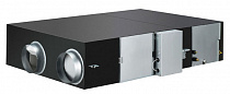
ERV
Система рекуперативной вентиляции LG LZ-H025GBA4
Система рекуперативной вентиляции LG LZ-H035GBA5
Система рекуперативной вентиляции LG LZ-H050GBA5
Система рекуперативной вентиляции LG LZ-H080GBA5
Система рекуперативной вентиляции LG LZ-H100GBA5
Система рекуперативной вентиляции LG LZ-H150GBA5
Система рекуперативной вентиляции LG LZ-H200GBA5

STANDARD Настенный тип
Настенный блок LG Standard ARNU05GSJC4
Настенный блок LG Standard ARNU07GSJC4
Настенный блок LG Standard ARNU09GSJC4
Настенный блок LG Standard ARNU12GSJC4
Настенный блок LG Standard ARNU15GSJC4
Настенный блок LG Standard ARNU18GSKC4
Настенный блок LG Standard ARNU24GSKC4
Настенный блок LG Standard ARNU30GSVA4
Настенный блок LG Standard ARNU36GSVA4
Колонный (3Ø)
Колонный блок LG Smart Inverter R410a UP48
Потолочные
Потолочный блок LG High Inverter R410a UV36
Потолочный блок LG High Inverter R410a UV48
Потолочный блок LG High Inverter R410a UV60
Четырехпоточный
Кассетный четырехпоточный блок LG MT06R
Кассетный четырехпоточный блок LG MT08R
Кассетный четырехпоточный блок LG CT09R
Кассетный четырехпоточный блок LG CT12R
Кассетный четырехпоточный блок LG CT18R
Кассетный четырехпоточный блок LG CT24R
Средненапорный тип
Канальный средненапорный блок LG CM18R
Канальный средненапорный блок LG CM24R
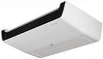
Потолочный
Потолочный блок LG CV18
Потолочный блок LG CV24
MULTI V WATER 4 Наружные блоки VRF водяного охлаждения (рекуперация теплоты)
Наружный блок LG Multi V Water IV ARWB080LAS4
Наружный блок LG Multi V Water IV ARWB100LAS4
Наружный блок LG Multi V Water IV ARWB140LAS4
Наружный блок LG Multi V Water IV ARWB200LAS4
Наружный блок LG Multi V Water IV ARWB220LAS4
Наружный блок LG Multi V Water IV ARWB240LAS4
Наружный блок LG Multi V Water IV ARWB280LAS4
Наружный блок LG Multi V Water IV ARWB300LAS4
Наружный блок LG Multi V Water IV ARWB340LAS4
Наружный блок LG Multi V Water IV ARWB400LAS4
Наружный блок LG Multi V Water IV ARWB420LAS4
Наружный блок LG Multi V Water IV ARWB440LAS4
Наружный блок LG Multi V Water IV ARWB480LAS4
Наружный блок LG Multi V Water IV ARWB500LAS4
Наружный блок LG Multi V Water IV ARWB540LAS4
Наружный блок LG Multi V Water IV ARWB600LAS4
Наружный блок LG Multi V Water IV ARWB620LAS4
Наружный блок LG Multi V Water IV ARWB640LAS4
Наружный блок LG Multi V Water IV ARWB680LAS4
Наружный блок LG Multi V Water IV ARWB700LAS4
Наружный блок LG Multi V Water IV ARWB740LAS4
Наружный блок LG Multi V Water IV ARWB800LAS4
Воздушного охлаждения (3Ø)
Наружный блок LG Multi V S ARUN040LSS0
Наружный блок LG Multi V S ARUN050LSS0
Наружный блок LG Multi V S ARUN060LSS0
Наружный блок LG Multi V S ARUN080LSS0
Наружный блок LG Multi V S ARUN100LSS0
Наружный блок LG Multi V S ARUN120LSS0
Блок управления вент. установкой
Блок управления вентиляционной установкой LG PRCKD21E
Блок управления вентиляционной установкой LG PRCKD41E
ТРВ
Терморасширительный Вентиль LG PATX13A0E
Терморасширительный Вентиль LG PATX20A0E
Терморасширительный Вентиль LG PATX25A0E
Терморасширительный Вентиль LG PATX35A0E
Терморасширительный Вентиль LG PATX50A0E
ARTCOOL Mirror
Кондиционер LG ARTCOOL Mirror AC09BQ
Кондиционер LG ARTCOOL Mirror AC12BQ
Hydro kit высокой температуры
Высоконапорный модуль LG Hydro Kit ARNH04GK3A4
Высоконапорный модуль LG Hydro Kit ARNH08GK3A4
ERV DX c фреоновым испарителем
Система рекуперативной вентиляции LG LZ-H050GXH4
Система рекуперативной вентиляции LG LZ-H080GXH4
Система рекуперативной вентиляции LG LZ-H100GXH4
Система рекуперативной вентиляции LG LZ-H050GXN4
Система рекуперативной вентиляции LG LZ-H080GXN4
Система рекуперативной вентиляции LG LZ-H100GXN4

ARTCOOL Gallery Настенный тип
Настенный блок LG Artcool Gallery ARNU07GSF14
Настенный блок LG Artcool Gallery ARNU09GSF14
Настенный блок LG Artcool Gallery ARNU12GSF14
Воздушного охлаждения (с рекуперацией тепла)
Наружный блок LG Multi V S ARUB060GSS4
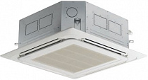
4-поточный Кассетный тип
4-поточный кассетный блок LG ARNU05GTRB4
4-поточный кассетный блок LG ARNU07GTRB4
4-поточный кассетный блок LG ARNU09GTRB4
4-поточный кассетный блок LG ARNU12GTRB4
4-поточный кассетный блок LG ARNU15GTQB4
4-поточный кассетный блок LG ARNU18GTQB4
4-поточный кассетный блок LG ARNU21GTQB4
4-поточный кассетный блок LG ARNU24GTPC4
4-поточный кассетный блок LG ARNU28GTPC4
4-поточный кассетный блок LG ARNU30GTPC4
4-поточный кассетный блок LG ARNU36GTNC4
4-поточный кассетный блок LG ARNU42GTMC4
4-поточный кассетный блок LG ARNU48GTMC4
4-поточный кассетный блок LG ARNU54GTMC4
Колонный тип
Колонный блок LG Smart Inverter R410a UP36WC / UU36WC
Колонный блок LG Smart Inverter R410a UP48WC / UU49WC1
4 поточный Кассетный тип Dual Vane
4х поточный кассетный блок DUAL VANE LG ARNU24GTBB4
4х поточный кассетный блок DUAL VANE LG ARNU28GTBB4
4х поточный кассетный блок DUAL VANE LG ARNU30GTBB4
4х поточный кассетный блок DUAL VANE LG ARNU36GTAB4
4х поточный кассетный блок DUAL VANE LG ARNU42GTAB4
4х поточный кассетный блок DUAL VANE LG ARNU48GTAB4
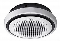
Круглый кассетный тип
Круглый кассетный блок LG ARNU24GTYA4
Круглый кассетный блок LG ARNU36GTYA4
Круглый кассетный блок LG ARNU48GTYA4
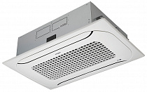
2-поточный Кассетный тип
2-поточный кассетный блок LG ARNU09GTSC4
2-поточный кассетный блок LG ARNU12GTSC4
2-поточный кассетный блок LG ARNU18GTSC4
2-поточный кассетный блок LG ARNU24GTSC4
1-поточный Кассетный тип
1-поточный кассетный блок LG ARNU07GTUB4
1-поточный кассетный блок LG ARNU09GTUB4
1-поточный кассетный блок LG ARNU12GTUB4
1-поточный кассетный блок LG ARNU18GTTB4
1-поточный кассетный блок LG ARNU24GTTB4
Четырехпоточный (3Ø)
Кассетный блок LG Smart Inverter R410a UT36W (3Ø)
Кассетный блок LG Smart Inverter R410a UT42W (3Ø)
Кассетный блок LG Smart Inverter R410aUT48W (3Ø)
Кассетный блок LG Smart Inverter R410a UT60W (3Ø)
Консольный тип
Консольный блок LG ARNU07GQAA4
Консольный блок LG ARNU09GQAA4
Консольный блок LG ARNU12GQAA4
Консольный блок LG ARNU15GQAA4
Низконапорный Канальный тип
Низконапорный канальный блок LG ARNU05GL1G4
Низконапорный канальный блок LG ARNU07GL1G4
Низконапорный канальный блок LG ARNU09GL1G4
Низконапорный канальный блок LG ARNU12GL2G4
Низконапорный канальный блок LG ARNU15GL2G4
Низконапорный канальный блок LG ARNU18GL2G4
Низконапорный канальный блок LG ARNU21GL3G4
Низконапорный канальный блок LG ARNU24GL3G4
Подмес свежего воздуха Канальный блок ПСВ
Канальный блок с подачей свежего воздуха LG ARNU76GB8Z4
Канальный блок с подачей свежего воздуха LG ARNU96GB8Z4
Напольно-потолочный тип
Напольно-потолочный блок LG ARNU09GVEA4
Напольно-потолочный блок LG ARNU12GVEA4
Потолочный тип
Потолочный блок LG ARNU18GV1A4
Потолочный блок LG ARNU24GV1A4
Потолочный блок LG ARNU36GV2A4
Потолочный блок LG ARNU48GV2A4
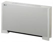
Напольный (с корпусом)
Напольный блок LG с корпусом ARNU07GCEA4
Напольный блок LG с корпусом ARNU09GCEA4
Напольный блок LG с корпусом ARNU12GCEA4
Напольный блок LG с корпусом ARNU15GCEA4
Напольный блок LG с корпусом ARNU18GCFA4
Напольный блок LG с корпусом ARNU24GCFA4
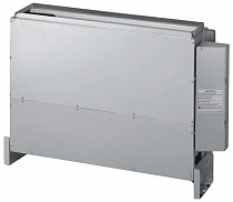
Напольный (без корпуса)
Напольный блок LG без корпуса ARNU07GCEU4
Напольный блок LG без корпуса ARNU09GCEU4
Напольный блок LG без корпуса ARNU12GCEU4
Напольный блок LG без корпуса ARNU15GCEU4
Напольный блок LG без корпуса ARNU18GCFU4
Напольный блок LG без корпуса ARNU24GCFU4
Ioniser (voice)
Кондиционер LG Ioniser CS09AWK
Кондиционер LG Ioniser CS12AWK
Ioniser
Кондиционер LG Ioniser CS09AWV
Кондиционер LG Ioniser CS12AWV
Blowkiss
Кондиционер LG Blowkiss S09KWH
Кондиционер LG Blowkiss S12KWH
3.0
Rated 3.0 out of 5
3.0 out of 5 stars (based on 1 review)
Your overall rating
LG MULTI V ARUV100LT3 (01) PDF MANUAL
Click here to download LG MULTI V ARUV100LT3 (01) PDF MANUAL
LG MULTI V ARUV100LT3 (01) PDF MANUAL
FREE ENGLISH PDF
OPERATING INSTRUCTIONS
USER GUIDE – USER MANUAL
OWNER GUIDE – OWNER MANUAL
REFERENCE GUIDE – REFERENCE MANUAL
INSTRUCTION GUIDE – INSTRUCTION MANUAL
Your overall rating
- YouTube
LG MULTI V ARUV100LT3 (01) PDF MANUAL
LG MULTI V ARUV100LT3 (01) PDF MANUAL

LG multi V ARUM Series Installation Manual

KM113.22MV2
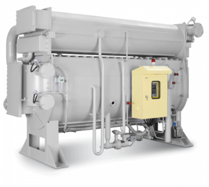
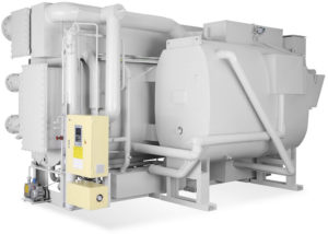
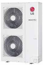
A SET FOR THE APPLICATION OF AN OUTDOOR COMPRESSOR CONDENSATION UNIT FOR A NONORIGINAL EVAPORATION / HVAC UNIT
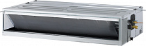
DESIGNED FOR OUTDOOR UNITS
LG Electronics
model series „ARUM–, ARUN–, ARUB–, ARWN—, ARWB–“
Version 2020/07/23
SAFETY
The equipment was designed to pose minimum risks during installation and for the operator during use. However, it is technically impossible to eliminate all risks and therefore, it is absolutely necessary to observe the below specified instructions.
MANIPULATION AND HANDLING
Upon delivery make sure that the equipment does not show any visible signs of damage and matches the parameters in the accompanying documentation.
SYMBOLS
Read the user’s guide before use.
INSTALLATION
The equipment may only be installed by a professional person possessing the necessary electrical an air-condition system qualification and skills.
The equipment may only be put into operation by a professional person possessing the necessary electrical and air-condition system qualification and skills.
OPERATION
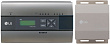
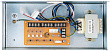
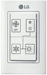
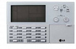
The operator uses information display, which installed under a transparent cover. The user is not allowed to interfere with the equipment in any way.
TECHNICAL PARAMETERS
| Technical parameters | |
| Lead wire terminals | Spring terminal WAGO max wire cross section 2.5 mm2 |
| Power supply | 230 V ~ AC ±10 %/50 Hz (e.g. from the connected outdoor unit)
Overvoltage category II Recommended cable CYKY-J 3×1.5 |
| Power input | Max. 30 W |
| Power supply of separate module KM113.22 | 24 V DC ±10 %/max. 800 mA, The source must be separated by double insulation (SELV) |
| Other connected devices | Must be separated by double insulation (SELV) |
| Communication properties with an outdoor unit | Two wires at RS485 safe voltage level |
| Parameters of Log. input (control) | 12 VDC/5 mA voltage (passive-switch by free contact) |
| Analogue input parameters | 10 VDC voltage with interconnected 0V potential, load
20 kohm (max. 0.5 mA) |
| Input temperature | DALLAS digital sensor, 3 m long (lengths 6 m and 10 m accessories to order) |
| Log. output parameters | Contact relay with load of 50 VAC/DC, maximum 200 mA |
| EEV output parameters | 24 VDC, 500 mA, inductive load, designed for valves EX4, EX5, EX6 |
| MODBUS communication | Serial line: RS485, 9.6 kbps, 8 bits, without parity, 1 stop bit |
| MOV-MV communication | Serial line: RS485 |
| Using the electronic module KM113 | Designed for installation with top layer overlap min. 1 mm |
| Mechanical parameters | |
| Width x Height x Depth | 310 x 246 x 145 mm (vertical installation on the wall) |
| Protection | IP65 based on the used cable glands |
| Work position | vertical |
| Mechanical durability | IK06 |
| Temperature | -25 °C to +55 °C |
| Humidity | 0 to 90 % without vapour condensation |
| Maximum altitude | 2000 m |
| Degree of pollution | 2 |
| Storage conditions | |
| Temperature | -25 °C to +60 °C |
| Humidity | 0 to 90 % without vapour condensation |
DESCRIPTION OF APPLICATION
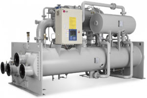
The communication module is designed for external control of an outdoor compressor unit called LG Electronics model range “MULTI V **“ in applications where the unit serves as the source of cold/heat in HVAC systems. The superior HVAC control system defines the operational mode and power requirements.
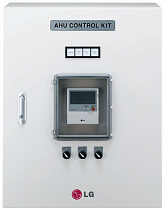
The communication module is installed in a plastic box including the necessary power supply. The delivered system includes refrigerant temperature sensors installed at the input and output of the heat exchanger in the HVAC equipment.
The module has an output for controlling a bipolar electronic expansion valve – model EX4–, EX5–, EX6– (ALCO/Emmerson).
In an application where the compressor unit is used as a source of refrigeration, expansion valves with a one-way refrigerant flow are used, i.e. EX4-M21, EX5-U21, EX6-M21.
In applications where the compressor unit is used as a heat source or as a source for several air handling units/exchangers, it is necessary to use expansion valves with bidirectional flow, i.e. EX4-U31, EX5-U31, EX6-M31.
The KM113.27UU module has 1 analogy input, 4 digital inputs, 2 digital outputs and 2 communication ports (RS485) for controlling the compressor unit. The MODBUS input/output is intended for communication with the superior I&C system. The “POWER“ output is intended for direct synchronous reduction of the compressor unit output according to the current power requirement.
GUARANTEED COMPATIBILITY OF THE KM113.22MV2 MODULE WITH COMPR. UNITS
|
Model range |
Name of the outdoor unit |
|
MULTI V 5 |
ARUM**LTE5 |
|
MULTI V S |
ARUN**GSS0 ARUN**LSS0 |
|
MULTI V WATER IV |
ARWN**LAS4 |
| MULTI V WATER IV HEAT RECOVERY |
ARWB**LAS4 |
| MULTI V S WATER |
ARWN**GA0 |
PERMITTED CAPACITY OF THE HEAT EXCHANGER IN THE HVAC EQUIPMENT
| Cooling performance kW | Heat exchanger capacity kW |
Expansion valve |
||||
|
kW |
kBtu/h |
Cooling mode |
Heat pump mode |
|||
| 05 | 18 | 4.6 | 5.6 | 5.1 | 6.3 | EX4-M21 / EX4-U31 |
| 07 | 24 | 5.7 | 8.2 | 6.4 | 9.2 | EX4-M21 / EX4-U31 |
| 10 | 36 | 8.3 | 10.6 | 9.3 | 11.9 | EX4-M21 / EX4-U31 |
| 12 | 42 | 10.7 | 12.3 | 12.0 | 13.8 | EX4-M21 / EX4-U31 |
| 14 | 48 | 12.4 | 14.1 | 13.9 | 15.9 | EX4-M21 / EX4-U31 |
| 16 | 54 | 14.2 | 15,8 | 16.0 | 18.0 | EX5-U21 / EX5-U31 |
| 22 | 76 | 15.9 | 22.4 | 18.1 | 25.2 | EX5-U21 / EX5-U31 |
| 28 | 96 | 22.5 | 28.0 | 25.3 | 31.5 | EX5-U21 / EX5-U31 |
| 33 | 115 | 28.1 | 33.6 | 31.6 | 37.8 | EX5-U21 / EX5-U31 |
| 39 | 134 | 33.7 | 39.2 | 37.9 | 44.1 | EX5-U21 / EX5-U31 |
| 45 | 153 | 39.3 | 44.8 | 44.2 | 50.4 | EX5-U21 / EX5-U31 |
| 50 | 172 | 44.9 | 50.4 | 50.5 | 56.7 | EX6-M21 / EX6-M31 |
| 56 | 192 | 50.5 | 56.0 | 56.8 | 63.0 | EX6-M21 / EX6-M31 |
| 62 | 215 | 56.1 | 62.0 | 63.1 | 69.4 | EX6-M21 / EX6-M31 |
| 67 | 236 | 62.1 | 67.0 | 69.5 | 75.7 | EX6-M21 / EX6-M31 |
| 73 | 253 | 67.1 | 73.0 | 75.8 | 82.3 | EX6-M21 / EX6-M31 |
| 78-123 | 279-468 | 1:1 application, capacity of the heat exchanger corresponds to
the output of the compressor unit |
1:1 application, capacity of the heat exchanger
corresponds to the output of the compressor unit |
EX6-M21 / EX6-M31 |
The capacity of the heat exchanger is determined under the following conditions:
Cooling mode: air temperature in front of the exchanger 27 °C, outside air temperature 35 °C
condensing temperature 45 °C, sub cooling 15 K, evaporating temperature 8 °C, superheating 3 K length of refrigerant connecting pipe 7.5 m, elevation 0 m
Heat pump mode: air temperature in front of the exchanger 20 °C, outside air temperature 7°C hot steam temperature 65 °C, condensing temperature 49 °C, sub cooling 5 K length of refrigerant connecting pipe 7.5 m, elevation 0 m
SYSTEM DESIGN
The design of the compressor unit – HVAC unit – I&C system is absolutely essential for proper function. Although this manual does not address the overall design of the system, we recommend that you check, among other things, when commissioning a system with a communication module:
- Size (volume) of applied heat exchanger in HVAC
- The amount of air passing through the heat exchanger in the HVAC
- Speed of air flow through the heat exchanger in HVAC
- The correct amount of refrigerant in the system with regard to the length of the piping and the size of the heat exchanger in the HVAC
- Air temperature in front of the heat exchanger. Permitted operating air temperature ranges – see the documentation of the respective compressor unit (usually 18 to 35 °C in “cooling” mode and 10 to 24 °C in “heat pump” mode)
- Function of the I&C system – the request for cooling or heating must not be activated if a sufficient air flow through the heat exchanger in the HVAC is not ensured
- Function of the I&C system in the “DEFROST” operating mode – the system must enable reliable removal of icing from the outdoor unit and at the same time solve the low air temperature behind the heat exchanger in the HVAC
The power request sent by the external I&C system is interpreted by the module as a temperature difference with respect to the required value. It is assumed that this requirement is in accordance with the real physical state of the heat exchanger – with decreasing power demand, the ability of the heat exchanger to transfer power decreases (smaller temperature difference, smaller amount of air, etc.).
The communication module in no way interferes with the control logic of the external condensing unit. Algorithms for controlling the speed of the invert compressor, condensing/evaporating pressure, etc. are included in the software of the specific LG compressor unit.
To directly limit the power of the compressor unit, the “power limit” module (MOV-MV accessory) must be installed.
When using MOV-UU, the algorithm of the compressor unit for changing the evaporating pressure/temperature of approx. 14 to 6 °C (approx. 11 to 8 bar) is activated according to the setting of power code C1 to C7. In the heat pump mode, according to the setting of power code H1 to H7, the algorithm of the compressor unit for activating the condensing pressure/temperature of approx. 33 to 49 °C (approx. 19 to 29 bar) is activated.
Attention, this temperature is variable according to the specific installation conditions (the above values apply to a pipe length of 7.5 m, elevation 0 m).


INSTALLATION – CONNECTION TO THE AIR-CONDITIONING SYSTEM
MECHANICAL INSTALLATION
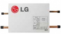
The communication box is to be installed near to the heat exchanger in the HVAC system – refrigerant temperature sensors and EEV module at the exchanger in the HVAC system are connected to the module (standard cable length of refrigerant temperature sensors on the evaporator is 3 m, sensors with a length of 6 m – accessories on request).
The plastic box allows the module to be installed in indoor or outdoor environments providing that safety installation procedures are observed (the box integrity is not compromised, suitable cable glands are used). If the box is installed outdoor, it is necessary to protect the box from direct UV radiation (shaded area). In this case, we recommend using a box with increased UV resistance (KM113.22UU-UV).
Preparation:
Remove the front cover from the installation box – loosen the 4 threaded locks at the cover corners. Now you may access the connection terminals of the communication module and the power supply source.
Have cable glands suitable for your intended application ready.
Attach the communication box to a suitable vertical plane (use the holes and covers at the rear of the box).

CONNECTION TERMINALS OVERVIEW
Connect a suitable power cable (e.g. CYKY-J 3×1.5) to the power supply terminals of the communication box – auxiliary terminals 1, 2, 3 (terminal block X1, 230 VAC – “L, N, PE”).
Connection terminals are divided into sections:

EEV MODULE CONNECTION (ELECTR. EXPANSION VALVE – EX4-, EX5-, EX6-)
Mechanical installation of the EEV module – see the relevant installation manual delivered with the EEV.
Electrical connection of EEV to the communication module:
Connect a suitable connecting cable between the EEV module and the “EEV” terminals on terminal block X1 in the installation box – terminals no. 6, 7, 8, 9.
ATTENTION!
The module MUST NOT be under voltage, when connecting the wires!
Follow the colour coding of the wires!
Changing the cable positions can damage the device.
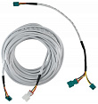
INSTALLATION, CONNECTION OF TEMPERATURE SENSORS
Attach thermal sensors TEMP1 (blue) and TEMP2 (red) to suitable locations on the heat exchanger in the HVAC system. The blue sensor is designed for “input” of the refrigerant into the heat exchanger, that is the small diameter pipes, and the “red” sensor is designed for “output” of the refrigerant from the heat exchanger – large diameter pipes. To properly attach sensors to Cu pipes use, for example fastening clamps to ensure proper heat transfer to the sensor – see Fig.
After the sensors are attached make sure to insulate them thermally from the environment.

Description: 1 – the most sensitive spot of the sensor
2 – maximizes the contact between the sensor and pipe

Installation description:

Create a loop on the sensor cable in order to prevent collection of water/humidity in the sensor connection.

Notice:
Incorrect installation of temperature sensors may result in incorrect control of the cooling process.
Incorrect installation of temperature sensors may permanently damage the refrigerant sensors.
CONNECTION OF REFRIGERANT TEMPERATURE SENSORS TO THE MODULE
Connect the temperature sensors TEMP1 and TEMP2 to the relevant terminals on the module. Sensor IN, blue (refrigerant temperature in front of the exchanger) connect to terminals TEMP1 (terminals no.10+11).
Sensor OUT, red (refrigerant temperature behind the exchanger) connect to terminals TEMP2 (terminals no. 12+13).
Follow the color coding of the sensors and wires – white wire to white terminal! Sensors are standardly supplied with a cable length 3 m.
Notice:
When the temperature sensor is connected incorrectly or is defective the safety function of the communication module is activated and the system generates corresponding error message (see the list of error messages of the applied LG unit).
Sensors with longer cable length on request.
CONNECTION TO AN OUTDOOR COMPRESSOR UNIT
Connect a suitable power cable between the power terminals of the outdoor compressor unit (see the diagram of the given unit) and the “supply” terminals in the communication box – terminal block no. 1-L, 2-N, PE.
Connect suitable (shielded) communication cable between the outdoor compressor unit (terminals “IDU“) and “OUT COMM” box terminals – terminal block X1, no. 3 (A) +4 (B).
Attention, the polarity must be followed (marked A, B).
MOV-MV POWER LIMITATION MODULE CONNECTION (ACCESSORIES)
Make sure that the compressor unit is without voltage!
There is a risk of electric shock and damage to the device when installing the module under voltage!
Compressor unit accepts the module only when the power supply is activated. Before connecting the power limitation module, address the system first!
Connect a suitable (shielded) communication cable between the terminals of the MOV-MV power limitation module and the “POWER COM” terminals no. 29 + 30.
Attention, the polarity (color of the terminals) must be followed.

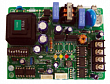
Install the MOV-MV power limitation module in the outdoor compressor unit – the module plugs into the connector on the PCB of the outdoor unit (example for the ARUN – LTE4 series outdoor unit).
ATTENTION, the orientation of the module in relation to the connector must be observed – see the MOV-MV module manual.
CONNECTION TO SUPERIOR I&C HVAC SYSTEM
CONTROL – DESCRIPTIONS, PRIORITIES
As for the external control the communication module allows you to use:
1/ “MODBUS“ communication protocol
2/ request on capacity through the use of 0…10V signal, operating mode via contact input
3/ request on capacity through the use of contact inputs (3 max), operating mode via contact input
The communication module respects priority of external signals as follows:
If the MODBUS communication sends at least one record from the recorded registries only commands from MODBUS will be respected (logic and analogue signals are ignored) until the power supply is turned off.
In the analogue signal is above the power output “1” the analogue input for the power value will be accepted as the control input.
If one of the two control inputs “MODBUS” or “analog” is not activated after switching on the power supply, the control by logic signals (contacts) is respected.
The connection is made directly at the terminals of the communication module KM113.22.
MODBUS PROTOCOL CONTROL (MONITORING) (see separate section for description)
INPUTS FOR EXTERNAL CONTROL – digital, analogue
OPERATION ACTIVATION (ON-OFF)
Input terminals “ON” – Logic input (voltage-free contact).
When the contact “0V + D4” is closed (terminals 18+22) the operation of the device is allowed, when it is opened the operation is stopped.
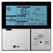
The current status of this input is indicated on the display by the size of the letter showing the selected operational mode.
Example:
„cO … 24 … 24“ = operational mode “cooling “, operation is not allowed
„CO … 24 … 24“ = operational mode “cooling“, operation is allowed
„hO … 24 … 24“ = operational mode “heat pump”, operation is not allowed
„HO … 24 … 24“ = operational mode “heat pump”, operation is allowed
OPERATIONAL MODE REQUEST “COOLING=C“, “HEAT PUMP=H“
Input terminals “MODE C/H” – Logic input (voltage-free contact)
When the contact “0V+DI1“ is closed (terminals 18+19) the communication module sends a request to switch the compressor unit from “cooling” mode to the “heat pump” mode = H“.
When the contact is off/open the communication module will send a request to switch the operational mode from “heat pump” back to the “cooling mode = C“.
“POWER LEVEL REQUEST”

Fig.4 – Control diagram – Power request for analogue input (Operational mode through logic input)
A request for power level may be executed through an analogue signal 0…10VDC or through 3 logic inputs (voltage free contacts).
To directly influence the output (change of evaporating temperature in cooling mode/change of condensing temperature in heat pump mode) it is necessary to install a capacity limitation module at the same time.
Input terminals “POWER 0…10V“ (terminals 16+17) – analogue signal 0…10V (0 V = no request for power level, 10 V = maximum power level request). The current power request is shown on the right side of the display module using 8 codes (“C0…C7“ or rather “H0…H7“).
The power request algorithm requires at least “C1″/”H1” code (i.e. at least 1.5V) to activate the compressor unit. The power request algorithm requires at least “C0″/”H0” code (that means maximum 1.3V) to stop the compressor unit.

Fig.5 – Logic input control diagram – free contact type
Input terminals “POWER 1ST,2ST,3ST“ – logic inputs (voltage free contacts): no contact closed = no power request contact POWER 1st closed (terminals 18+20) = low power request contact POWER 2st closed (terminals 18+21) = higher power request both contacts POWER 1ST+2ST closed (terminals 18+20+21) = maximum power request the current power demand is displayed on the right position of the module display via 4 codes (“C0, C1, C3, C7, “ or “H0, H1, H3, H7”)
OUTPUTS – INFORMATION ABOUT THE OPERATIONAL STATUS OF THE EQUIPMENT
DEFROST
Logic output “DEFROST”(terminals 23 + 24).
The contact is closed if the equipment is in the “defrost” mode and at the same time the display module shows an information message “d F”
During normal operation of the device, the contact is open.
ERROR
Logic output “ERROR“(terminals 25+26).
The contact is off/open if the equipment diagnostics identified a defect or the equipment is not powered – no supply voltage.
The defect code is also shown on the module display using the variable communicated by the MODBUS.
Defects identified by the communication module:
Er .. 2 thermometer error “blue”
Er .. 6 thermometer error “red”
Er .. 99 Modbus communication error
Er .. 5 Communication error with the outdoor unit
Er .. XX outdoor unit errors
List of error codes of the outdoor unit – see the servicing manual of the applied LG equipment.
If more than one error has occurred at the same time, only the code of the first error is shown on the display.
During regular operational status the contact is on/closed.
Notice:
To restart the device after errors occur, it is NECESSARY to perform a “RESET” of the compressor unit device, i.e. disconnect the device from the power supply.
CONTROL / COMMUNICATION MODBUS
In order to control up to 23 modules from the superior system you may use the MODBUS communication as an option to control or monitor the equipment.
Input/output “MODBUS“ (terminals 23+24)
The address for MODBUS communication is set using the “SETTINGS” button. The setting procedure to be found in paragraph 6.

Fig.6 – MODBUS communication wiring diagram for controlling multiple modules
PARAMETRY KOMUNIKACE MODBUS
Serial line: 9.6 kbps, 8 bits, no parity, 1 stop bit Station address: hex91 – hexA7 (default hex91)
Supported functions:
– 3 (Multi_Read)
– 6 (Single_Write)
– 16 (Multi_Write)
READING REGISTRIES
|
Name |
Address
(decadically) |
Properties/description |
| VERSION | 4096 | Software version |
| ERROR | 4097 | Errors according to the device’s self-diagnostics (see the service manual of the LG device), (error 99 + Modbus communication error) |
| TEMP1 | 4098 | Refrigerant input temperature to the exchanger +15 °C (blue sensor, smaller diameter) |
| TEMP2 | 4099 | Refrigerant output temperature to the exchanger +15 °C (red sensor, bigger diameter) |
| DEFROST | 4100 | 1 = active defrost mode of the outdoor unit |
RECORDING REGISTRIES
|
Name |
Address
(decadically) |
Properties/description |
|
| POWER | 4101 | The value of the required power 0 to 7 corresponds with analogue input | |
| FUNCTION | 4102 | Bit 0 | 0 = cooling; 1 = heating (heat pump) |
| Bit 1+2 | Power value 0,1,2,3 (this value is used to control the power only if the value in the registry POWER is = 0) | ||
| Bit 3 | 0 = OFF; 1 = ON | ||
| Bit 6 | 1 = RESET |
| POWER | |||||||
|
7 |
6 | 5 | 4 | 3 | 2 | 1 |
0 |
| A2 | A1 |
A0 |
|
FUNCTION |
|||||||
|
7 |
6 | 5 | 4 | 3 | 2 | 1 | 0 |
| RESET | OFF/ON | L1 | L0 |
C / H |
The RESET function is used for example when you need to transfer the control of hardware to signals without the need to shut down the power supply to the unit.
When the communication is activated through the first record it is necessary to communicate more often than during 50 seconds (the recommended communication frequency is once every 1 to 10 second).
If writing is not repeated, the situation will be considered as a MODBUS communication error (error Er 99).
Notice: If an error is active (ER–), the registers are automatically set to “0”.
Reading the values of the read registers is possible at any time without time limit and does not affect the
control by HW signals.
CONFIGURATION AND CONNECTION CHECK
SETTING THE POWER CODE AND MODBUS COMMUNICATION ADDRESS
Power code and address for MODBUS communication are set using the button “SETTINGS/CAPACITY/MODBUS ADDRESS“.
Setting procedure:
ENTERING THE “SETTINGS” MODE
1. Press the SETTINGS button while turning on the power to the module
– Entering the setting mode is indicated on the display by a character:

ENTERING THE “POWER CODE SETTING” MODE
2. Hold the SETTINGS button for 5 s.
– The display shows the set power code in kW.
– The power code can be changed by shortly pressing the SETTINGS button. It changes cyclically according to the following table
|
Cooling power |
kW | 05 | 07 | 10 | 12 | 14 | 16 | 22 | 28 |
|
Btu |
18 | 24 | 36 | 42 | 48 | 60 | 80 | 100 | |
| kW | 33 | 39 | 45 | 50 | 56 | 62 | 67 |
73 |
|
| Btu | 120 | 140 | 160 | 180 | 200 | 220 | 240 |
260 |
ENTERING THE “MODBUS ADDRESS SETTING” MODE
3. Hold the SETTINGS button for 5 s.
– The display shows the set address for MODBUS communication. This address is also usable for LG central control systems.
The MODBUS address can be changed by briefly pressing the SETTINGS button. It changes cyclically from 90 to A7. (90 = service communication; 91,…, A7 = MODBUS communication)
|
Address |
90 | 91 | 92 | 93 | 94 | 95 | 96 | 97 |
|
99 |
9A | 9B | 9C | 9D | 9E | 9F |
A0 |
|
| A1 | A2 | A3 | A4 | A5 | A6 | A7 |
ENTERING THE “PROGRAM SELECTION” MODE
4. Hold the SETTINGS button for 5 s
– The display shows the setting of the active program “0“.
– Service settings – do not change the program
5. Hold the SETTINGS button for 5 s to return to point 2.
If you do not press the SETTINGS button for 10 seconds, the last set value is automatically saved, the setting mode is exited and the initial information sequence appears on the display.
Attention! After changing the settings, it is necessary to restart the outdoor unit (restore power). If the outdoor compressor unit is not restarted, the changes are not accepted by the unit.
SETTING THE INTERNAL SYSTEM ADDRESS (AUTO-ADRESSING PROCESS)
When starting the system for the first time, it is necessary to perform auto-addressing of the system – see the relevant installation manual for the outdoor compressor unit. During the addressing process, the “- -“ symbol appears on the display. After the addressing is completed, the display shows the assigned module address in hexadecimal format (for approx. 10s).
The assigned address is displayed in the introductory information sequence:
1st cycle – basic hardware and software setting information – example:
“LG … Ar … 56 … So … 4.3 …So … 3“
Explanation – module designed to communicate with the compressor unit, model series ARUM/N, power code set to 56kW, software version 4.3, user software 3
2nd cycle – basic hardware and software setting information – example:
“LG … Ar … 56 … So … 4.3 … So … 3 … 11“
Explanation – module designed to communicate with LG compressor unit, ARUN model series, power code set to 56kW, software version 4.3, user software 3, assigned station / address number “1“ for communication with ARUM— outdoor unit.
Notice:
If no address has been assigned to the module, the symbol “- – “ will be displayed in the appropriate position for the address in the introductory sequence – i.e. the system did not auto-address successfully, the outdoor compressor unit does not communicate with the KM113.22MV2 module.
If several communication modules are connected to one outdoor compressor unit, each module must have different address.
Upon delivery, the module is delivered with the preset address “1”.
After these initial sequences, the display will show current status of the operation request
Example
“cO … -1 … 6““
Explanation: cooling operating mode, no operation allowed, no power demand, current temperature of the input refrigerant piping to the heat exchanger in HVAC -1 °C (blue sensor), on the output +6 °C (red sensor). Refrigerant temperature display range MIN = -9, MAX= 99.
Attention:
If the power code is set incorrectly, the safety function of the external compressor unit may be activated.
When setting the power code, both the module and the device must be without voltage (changing the power code is accepted by the module when the power supply is activated).
Notice:
If several communication modules are connected to one outdoor compressor unit, each module must have a different address. The address of the communication module(s) for internal communication between the outdoor unit and the modules is assigned automatically during the auto-addressing process (the process is activated from the outdoor unit).
ADDRESS OF COMMUNICATION MODULE FOR COMMUNICATION WITH COMPRESSOR UNIT:
The address of the communication module(s) for internal communication between the outdoor unit and the modules is assigned automatically during the auto-addressing process. The process is activated from the outdoor unit (see the relevant manual for the outdoor compressor unit).
Display of the assigned address – see section “Introductory information sequence”.
COMMUNICATION MODULE ADDRESS FOR CENTRAL CONTROL IN THE LG SYSTEM:
The address of the communication module(s) for central control via the LG protocol (central controller/converter) is identical to the MODBUS address.
INTRODUCTORY INFORMATION SEQUENCE
Communication module functionality test
Activate the supply voltage – the display will show the introductory sequence:
1ST cycle – basic information about hardware, settings and software – example:
“LG … Ar … 56 … So … 4.3 … So … 3“
2nd cycle – basic information about hardware, settings, software and assigned address – example:
”LG … Ar … 56 … So …4.3 … So … 3 … 1“
Meaning – module designed for communication with the LG compressor unit, ARUM / N model series, set power 56kW, software version 4.3, user software 3, assigned station number/address “1” (set on delivery).
After these initial sequences, the display will show the current status of the operation request – example:
“cO … -1 … 6““
Explanation: cooling operating mode, no operation allowed, no power demand, current temperature of the input refrigerant piping to the heat exchanger in HVAC -1 °C (blue sensor), on the output +6 °C (red sensor). Refrigerant temperature display range MIN = -9, MAX= 99.
INSPECTION OF INPUTS / OUTPUTS – TESTS
WARNING! All the described functionality tests may ONLY be done by an authorized person. Incorrect test performance may result in equipment breakdown. Make sure that the test will not damage the equipment or endanger persons near the equipment!
INPUT TESTS – temperature sensors
1. Test for the presence of the refrigerant temperature sensor at the input to the heat exchanger (terminals TEMP1, blue) – if the sensor is defective or the connection is incorrect, “Er-2” error flashes on the LED display. Status of this input is permanently indicated by the LED below the display (blue LED is lit = module communicates with the sensor).
2. Test for the presence of the refrigerant temperature sensor at the output from the heat exchanger (terminals TEMP2, red) – if the sensor is defective or the connection is incorrect, “Er-6” error flashes on the LED display. Status of this input is permanently indicated by the LED below the display (red LED is lit = module communicates with the sensor).
INPUT TESTS – power request
The power request is processed by the module only if the operation of the compressor unit is enabled – closed contact „ON (DI4). If a power demand is active at the module input and the operation of the compressor unit is not enabled (contact ON is open), the device will not be activated.
If the operation of the compressor unit is blocked, but at the same time the power demand is active, this state can be recognized by the case of the operation request letter on the display (e.g. “C4” = cooling request, operation enabled, “c4” = cooling request, operation not allowed).
3. The analog input test is performed by applying a DC voltage of 0-10 V to the “POWER 0–10 V” terminals. The display shows the value C0, C1,…, C7. Since we need 8 positions for the range 0-10 V, the voltage for a change of one degree is about 1.4 V. (ATTENTION, at the same time “operation must be” – contact “ON” closed.)
4. Test of logic (contact) input for power switching – disconnect the analog voltage and perform a test of logic inputs, gradually connect the terminals “POWER 1st / 2st / 3st” with a suitable wire. When the “0V” terminals are connected to the “DI2” terminal, power stage 1 is activated – the display shows the value C1. When the “0V” terminals are connected to the “DI3” terminal, power stage 2 is activated – the value C3 appears on the display. When the “0V” terminals are connected to the “DI2” and “DI3” terminals at the same time, power stage 3 is activated – the value C7 appears on the display. (ATTENTION, at the same time “operation must be” – contact “ON” is closed.)
5. Logic (contact) input test for switching the operating mode – disconnect all power request and connect the “MODE C / H” terminals with a suitable wire. When the “0V” terminals are connected to the “DI1” terminal, the heat pump operating mode is activated – the “H0” character appears on the display. Now we connect the power request – the corresponding request (“H1″….) Will appear on the display.
Example of displayed requests:
„C3 … 6 … 8““
„H2 … 58 … 37““
OUTPUT TESTS
6. Error message test – if we disconnect for example the temperature sensor TEMP1, an error will occur, see the display, and output ERROR opens the contact.
Example of displayed errors: „Er-2-Er-2-Er-2… “
If the system diagnoses several errors at the same time, only the error that occurred first will be displayed. After removing it, the second error will be displayed.
7. DEFROST function test always after activating the power supply of the module, the contact closes momentarily for testing reasons (approx. 2 s).
Notice: This output is necessary for the correct function of the “HVAC compressor unit” system in “heat pump” mode. The superior HVAC control system must ensure the correct appropriate response of the HVAC system.
After performing the tests, check the tightness of the bushings and reattach the cover of the installation box and visually check its tightness.
INSPECTION OF SETTINGS DURING OPERATION
During operation, without deactivating the supply voltage, the pressure status of the system (if a pressure sensor is installed), the set power code, the address for central control (MODBUS) and the last 10 error states of the device can be verified.
- After a short press of the SETTINGS button, the display shows the pressure (in bar). If the pressure gauge is not used, 0 is displayed.
- Hold the SETTINGS button for approx. 5 s.
The display shows the set power code in kW - Hold the SETTINGS button for approx. 5 s.
The display shows the set address for MODBUS communication. This address is usable (same) for LG central control systems. - Hold the SETTINGS button for approx. 5 s.
The display shows numerical code of the selected user program for controlling the EEV.
In this mode, the values can be viewed, not changed. The “current setting information” mode ends automatically after approx. 5 s and the display shows the current status of the operating requirements and the temperature values.
Warranty card
Equipment specifications
| Product
communication box to control outdoor compressor condensation unit LG Electronics. model series “ARUN**” output for bipolar expansion valve control EX5, EX6 |
Model KM113.22MV2 |
| Scope of delivery – accessories Serial number
communication module KM113.22MV2 power supply (24 VDC), switch, Refrigerant temperature sensor “BLUE” (TEMP1-IN = small ) refriegerant temperature sensor “RED” (TEMP2-OUT“ = large ) installation box, auxiliary terminals, cable glands (6pcs), installation manual |
|
| Date of sale | Seller |
| Installation date | Installation performed by |
The manufacturer provides a 24-month warranty covering the quality of the product starting on the day of sale. The warranty covers defects of the purchased product, which appear during the warranty period. In order to keep your warranty valid the installation must be performed by an authorized person and the “Warranty form” must be properly filled out. The client shall always claim the given warranty rights at his own seller.
Service contacts
-

LG
Технический каталог на внутренние блоки LG Multi V IV 2014
Скачать
Pdf 31.02 Mb
год: 2014 | Язык: RU -
LG
Технический каталог на наружные блоки VRF системы LG Multi V IV. Серия ARUN**LTE4
Посмотреть
Скачать
Формат: pdf|
44.83 Mb
год: 2014 | Язык: RU

