
![]()
BEDIENUNGSUND MONTAGEANLEITUNG OPERATING AND INSTALLATION INSTRUCTIONS INSTRUCTIONS DE MONTAGE ET MANUEL D’UTILISATION

Verehrte Kundin, geehrter Kunde!
Mit dem Vaillant Regelgerät VRC 420 haben Sie ein Spitzenprodukt aus dem Hause Vaillant erworben. Um alle Vorteile des Gerätes richtig nutzen zu können, nehmen Sie sich ruhig ein paar Minuten Zeit und lesen Sie diese Bedienungsanleitung. Sie ist nicht kompliziert und gibt Ihnen nützliche Tips und Tricks.
Bitte bewahren Sie diese Anleitung sorgfältig auf und geben Sie sie einem evt. Nachbesitzer weiter.
Zu Ihrer Sicherheit!
Alle Arbeiten am Gerät selbst und am Gesamtsystem dürfen nur autorisierte Fachleute durchführen!
Bitte bedenken Sie, daß bei nicht fachgerecht ausgeführten Arbeiten Gefahr für Leib und Leben bestehen kann.
TIPPS!
●Beachten Sie die werkseitigen Einstellungen auf Seite 22. Sind Sie damit zufrieden, brauchen Sie keine weiteren Einstellungen vorzunehmen.
●Nehmen Sie bei allen Einstellvorgängen die Ausklappseiten am Anfang und am Ende dieser Anleitung zu Hilfe.
Dear customer!
By choosing the VRC 420 thermostat you have bought a high quality product from Vaillant. In order to familiarise yourself with all aspects of this thermostat it is recommended that you take some time and carefully read this instruction manual. It is easy to understand and will give you many useful hints.
Please keep the manual in a safe place and make sure that handed over to possible next owners of the control.
For your safety!
All repairs on the thermostat itself and your overall system should always be carried out by authorised professionals only!
Please take into consideration that nonprofessional interference with the appliance could threaten lives.
Hints!
●Please note the list of settings which have been already programmed into the thermostat on page 14. If you are happy with these settings no further programming is necessary.
●Refer to the folded pages at the beginning and the end of this manual for re-programming the thermostat.
FR
Chère cliente, cher client!
Avec le régulateur VRC 420 de Vaillant, vous venez d’acquérir un produit haut de gamme. Pour pouvoir profiter au maximum de tous les avantages de l’appareil, n’hésitez pas à réserver quelques minutes à la lecture de ce mode d’emploi. Il n’est pas compliqué et vous fournit des «tuyaux» bien utiles. Conservez soigneusement ce document et donnez-le, le cas échéant, au propriétaire ultérieur.
Pour votre sécurité!
Sur l’appareil lui-même et sur l’ensemble du système, les travaux ne doivent être réalisés que par des spécialistes qualifiés!
Risques corporels graves si les travaux ne sont pas effectués selon les règles.
QUELQUES «TUYAUX»
●Examinez les réglages effectués par le constructeur (page 16). S’ils vous conviennent, vous n’avez pas besoin d’en effectuer d’autres.
●Lors de tous les réglages, aidez-vous des rabats du début et de la fin de ce mode d’emploi.
2

DE
Auf Seite 82 finden Sie eine Übersicht über die Bedienelemente unter dem Gerätedeckel (5)
GB
See page 82 for an overview of the operating elements located under the cover panel (5)
FR
En page 82, vous trouverez un récapitulatif des organes de commande sous le couvercle de l’appareil (5)
|
7 |
5 |
G 6 H |
|
VRC-VCC
VRC-VC2_001/0
3

Bedienelemente
1Tag-Temperaturwähler
zur Einstellung der gewünschten Raumtemperatur.
2Partytaste/einmaliges Laden des Speichers
zur vorübergehenden Abschaltung des Heizprogramms oder zum einmaligen Aufheizen des Speicherwassers.
5Gerätedeckel
6Display
Das Display gibt Auskunft über Uhrzeit und Wochentag sowie über Status und Betriebsart des Reglers.
7Betriebsartenschalter
 Stellung „Programm“
In dieser Stellung wird die Raumtemperatur vom eingegeben Programm geregelt.


 Stellung „Heizen“
In dieser Stellung wird die Raumtemperatur ständig nach der Temperatur geregelt, die am Tag-Temperaturwähler (1) eingestellt ist.
 Stellung „Absenken“ .
In dieser Stellung wird die Raumtemperatur ständig nach der Absenk-Temperatur (Nacht-Temperatur) geregelt.
Heizkreise:
Tragen Sie hier bitte ein welche Räume über die beiden Heizkreise (HK) geregelt werden:
HK1:
HK2:
DE
Display, Übersicht
AWochentag
BStatusanzeige:
Heizbetrieb Das Gerät befindet sich im Heizbetrieb. Warmwasser Das Gerät befindet sich im Warmwasser-
betrieb.
Party Das Gerät befindet sich im Party-Betrieb (siehe Seite 10).
Die Anzeige „Heizbetrieb“ wird überdeckt, weil in dieser Betriebart Heizung und Warmwasser zur Verfügung stehen.
1x Ladung Das Gerät lädt den Warmwasserspeicher einmalig auf (siehe Seite 11).
Urlaub Das Ferienprogramm ist aktiv.(s. Seite 36)
Fehlermeldungen (siehe Seite 48)
Störung Das Heizgerät hat eine Störung Verbindung Die Datenübertragung vom Regler zum
Heizgerät ist gestört.
HK2 VT Sensor Die Verbindung zum Vorlauftemperatursensor ist gestört.
Wartung Das Heizgerät muß gewartet werden.
CAußentemperatur
DBetriebsart „Absenken“
EBetriebsart „Heizen“
FBetriebsart „Programm“
GAktuelle Uhrzeit
HAktuelle Temperatur (Anzeige nur bei Wandmontage)
4

DE
Bedienungsanleitung . . . . . . . .3
1 Geräteübersicht . . . . . . . . . . . . .3,82 1 Gerätebeschreibung . . . . . . . . . . . . .8 2 Bedienung . . . . . . . . . . . . . . . . . . .9
2.1 Raumtemperatur einstellen . . . . . .9 2.2 Lüften . . . . . . . . . . . . . . . . . . .10 2.3 Partyfunktion einschalten . . . . . .10 2.4 Speicher einmalig aufheizen . . . .11
3 Energiespartipps . . . . . . . . . . . . . .12 4 Grundeinstellungen . . . . . . . . . . . .13
4.1 Betriebsart wählen . . . . . . . . . .13 4.2 Landessprache wählen . . . . . . .14
4.3Uhrzeit/Wochentag einstellen . . .16
4.4Absenktemperatur einstellen . . . .18
4.5 Heizkurve einstellen . . . . . . . . .20
5 Zeitprogramme . . . . . . . . . . . . . .22
5.1 Werkseitige Einstellungen . . . . . .22 5.2 Übersicht . . . . . . . . . . . . . . . . .24 5.3 Heizkreis wählen . . . . . . . . . . .26 5.4 Heizzeiten einstellen . . . . . . . . .26
5.5Warmwasserzeiten einstellen . . .34
5.6Zirkulationszeiten einstellen . . . .35
5.7Ferienprogramm aktivieren . . . . .36
6 Sonderfunktionen . . . . . . . . . . . . . .38
7 Info-Anzeige . . . . . . . . . . . . . . . . .47
8 Fehlermeldungen . . . . . . . . . . . . . .48
9 Frostschutz . . . . . . . . . . . . . . . . . .49
10 Datenübertragung . . . . . . . . . . . .49
11 Telefonfernschaltung . . . . . . . . . . .50
12 Werkseinstellung . . . . . . . . . . . . .50
13 Werksgarantie . . . . . . . . . . . . . . .51
Montageanleitung . . . . . . . . .53
|
GB |
FR |
||||
|
CONTENTS |
Page |
TABLE DES MATIERES |
Page |
||
|
Operating instructions . . . . . . .3 |
Mode d’emploi . . . . . . . . . . . .3 |
||||
|
1 |
Thermostat overview . . . . . . . . |
.3, 82 |
1 |
Vue d’ensemble de l’appareil |
. . .3, 82 |
|
1 |
Description of the appliance . . . . |
. . .8 |
1 |
Description de l’appareil . . . |
. . . . . .8 |
|
2 |
Operation . . . . . . . . . . . . . . . . . |
. . .9 |
2 |
Commande . . . . . . . . . . . . . . |
. . . . .9 |
|
2.1 |
Adjusting day temperature . |
. . . . .9 |
2.1 |
Réglage de la température jour . . .9 |
||||
|
2.2 |
Ventilation . . . . . . . . . . . . |
. . . .10 |
2.2 |
Ventilation/aération local . . . |
. . .10 |
|||
|
2.3 |
Override mode |
10 |
2.3 |
Touche party . . . . . . . . . . . |
. . .10 |
|||
|
2.4 Réchauffage prioritaire du ballon .11 |
||||||||
|
2.4 |
One-off heating up of tank |
. . . .11 |
3 |
Quelques «tuyaux» pour vos |
||||
|
3 |
Energy saving hints . . . . . . . . . |
. . .12 |
économies d’énergie |
12 |
||||
|
4 |
Basic settings |
13 |
4 |
|||||
|
Pour effectuer les réglages de base 12 |
||||||||
|
4.1 |
Choose operating mode |
13 |
4.1 |
. |
||||
|
Choix du mode de fonctionnement13 |
||||||||
|
4.2 |
Choose a language . . . . . . |
. . .14 |
4.2 |
Choix de la langue . . . . . . . . |
. .14 |
|||
|
4.3 |
Date & time setting . . . . . . . |
. . .16 |
4.3 |
Réglage de l’heure et du jour |
. . .16 |
|||
|
4.4 |
Adjusting night temperature |
. . . .18 |
4.4 |
Réglage de la temp. nocturne |
. . .18 |
|||
|
4.5 |
Setting the heating curve . . . |
. . .20 |
4.5 |
Réglage de la courbe de chauffe .20 |
||||
|
5 |
Heating periods . . . . . . . . . . . |
. . .22 |
5 |
Les périodes de chauffage . . . . . |
. .22 |
|||
|
5.1 |
Pre-set values . . . . . . . . . . . |
. . .22 |
5.1 |
Réglages du constructeur . . . . |
. .22 |
|||
|
5.2 |
Overview . . . . . . . . . . . . . |
. . .24 |
5.2 |
Présentation générale . . . . . . |
. .24 |
|||
|
5.3 |
Selection of heating circuit . . . . .26 |
5.3 |
Choisir le circuit de chauffage |
. .26 |
||||
|
5.4 |
Programming heating periods . . .26 |
5.4 |
Programmer les périodes de |
26 |
||||
|
5.5 |
Set hot water supply periods . |
. . .34 |
chauffage . . . . . . . . . . . . . . . . |
|||||
|
5.6 |
Set circulating periods . . . . . |
. . .35 |
5.5 |
Régler les périodes d’ ECS . . . . .34 |
||||
|
5.7 |
Holiday program . . . . . . . . |
. . .36 |
5.6 |
Régler les périodes de recyclage .35 |
||||
|
6 |
Special functions . . . . . . . . . . . |
. . .38 |
5.7 |
Programme de congés . . . . . . |
. .36 |
|||
|
7 |
Display of information |
47 |
6 |
Fonctions spéciales . . . . . . . . . . . |
. .38 |
|||
|
7 |
Affichage d’informations . . . . . . |
. .47 |
||||||
|
8 |
Error messages . . . . . . . . . . . . |
. . .48 |
8 |
Messages d’erreur . . . . . . . . . . . |
. .48 |
|||
|
9 |
Frost Protection . . . . . . . . . . . . |
. . .49 |
9 |
Protection contre le gel . . . . . . . . |
. .49 |
|||
|
10 Data transfer . . . . . . . . . . . . . |
. . .49 |
10 Transfert de données . . . . . . . . |
. .49 |
|||||
|
11 Remote control . . . . . . . . . . . . |
. . .50 |
11 Commande à distance . . . . . . . |
. .50 |
|||||
|
12 Factory-adjusted elements . . . . |
. . .50 |
12 Réglage usine . . . . . . . . . . . . . |
. .50 |
|||||
|
13 Manufacturer’s Warranty . . . . |
. . .51 |
13 Garantie usine . . . . . . . . . . . . . |
. .51 |
|||||
|
Installation instructions . . . . .53 |
Instructions de montage . . . . .53 |
5

|
GB |
|
|
Operating elements |
Display, Overview |
1Day temperature selector
for adjusting to required room temperature.
2Override/one-off filling of tank
for temporary deactivation of heating program or for oneoff heating up of tank water (Domestic hot water for VUW combination boilers only in GB).
5Device cover
6Display
The display shows the time and day, along with controller mode and status information
7Operating mode switch
 ”Program“ setting
In this setting, the room temperature is controlled by the pre-set program.


 “Heating“ setting
In this setting, the room temperature is permanently controlled according to the temperature pre-selected on the day-temperature selector (1).
 “Reduce“ setting
In this setting, the room temperature is permanently controlled according to the reduced (night) temperature.
Heating circuits:
Please indicate at this point which rooms are to be controlled via the two heating circuits (HC):
HC1:
HC2:
ADay of the week
BStatus indicator
Heating on The appliance is in heating mode.
Hot water The appliance is in hot water mode. Party The appliance is in party (override) mode
(see page 10).
The “Heating mode“ display message is blocked-out as heating and hot water are both available in this operating mode.
DHW Boost The appliance fills the hot-water tank on a single occasion (see page 11).The appliance activates the warmstart of the Aqua-Comfort system. (ecoMax 800 only)
Holiday The holiday program is active (see p. 36).
Error messages (see page 48)
Appl. Fault There is heating system fault.
Conn. Fault Data transfer from the controller to the heating unit has been interrupted.
CH2 Fault The connection to the flow temperature is malfunctioning.
Maintenance The heating appliance must be serviced. (only available with compatible boiler and electronics; not available in GB)
COutside temperature
DOperating mode «Night setting”
EOperating mode «Heating”
FOperating mode «Program”
GActual time
HActual temperature
(only shown on wall-mounted version)
6

|
FR |
|
|
Organes de commande |
Vue d’ensemble de l’écran |
1Sélecteur de température jour
pour le réglage de la température ambiante souhaitée.
2Touche party/Remplissage exceptionnel du ballon Pour une déconnexion provisoire du programme de
chauffage ou pour le chauffage unique de l’eau du ballon.
5Couvercle de l’appareil
6Ecran
7Commutateur de mode de fonctionnement
 POSITION „Programme“
Dans cette position, la température ambiante est régulée par le programme entré.


 POSITION „Chauffage“
Dans cette position, la température ambiante est réglée constamment en fonction de celle qui est paramétrée sur le sélecteur de température jour (1).
 POSITION „Abaisser“ .
Dans cette position, la température ambiante est réglée constamment en fonction de la température de baisse (température de nuit).
AJour
BAffichages d’état
Fonct. chauff L’appareil se trouve en mode chauffage.
|
Chauffe eau |
L’appareil se trouve en mode chauffe eau. |
|
Party |
L’appareil se trouve en mode Party |
|
(voir page 10). |
|
|
L’affichage „mode chauffage“ est |
|
|
recouvert, car dans ce mode, le |
|
|
chauffage et l’eau chaude sont |
|
|
disponibles. |
|
|
1x charg. accu |
L’appareil charge exceptionnellement le |
|
ballon d’eau chaude (voir page 11). |
|
|
Congés |
Le programme de congés est actif (voir |
|
page 36) |
|
|
Messages d’erreur (voir page 48) |
|
|
Dérangement |
L’appareil de chauffage a une panne |
|
Défaut Conn° |
La transmission de données entre le |
|
régulateur et l’appareil de chauffage est |
|
|
perturbée |
|
|
Cons adm. CC2 |
La connexion avec la sonde de |
|
température départ est perturbée. |
|
|
Maintenance |
L’appareil de chauffage a besoin d’une |
|
révision. |
Circuits de chauffage:
Veuillez entrer les pièces qui doivent être régulées par les deux circuits de chauffage (CC):
CC1:
CC2:
CTempérature nocturne réglée
DMode de fonctionnement «Abaisser»
EMode de fonctionnement «Chauffer»
FMode de fonctionnement «Programme»
GHeure actuelle
HTempérature actuelle
(Affichage uniquement en fixation murale)
7

DE
1 Gerätebeschreibung
Das Regelgerät ermöglicht die witterungsgeführte Vorlauftemperatur-Regelung zweier Heizkreise, eines Brennerkreises und eines Mischerkreises z. B. für die Fußbodenheizung. Darüber hinaus kann es die Warmwasserbereitung und eine Zirkulationspumpe steuern.
Der Außentemperaturfühler mißt ständig die aktuelle Außentemperatur. Das Regelgerät sorgt dafür, dass die eingestellte Raumtemperatur — bei voll geöffneten Thermostatventilen — erreicht wird. Hierfür muß das Heizgerät eine bestimmte Vorlauftemperatur bereitstellen.
Sobald der Regler angeschlossen ist und die Uhrzeit eingestellt ist, führt er ein sinnvolles Heizprogramm durch. Hierfür muß der Betriebsartenschalter (7, vordere Klappseite) in der Stellung „Programm“
 stehen.
Ausführung mit DCF-Empfänger
Der im Lieferumfang enthaltene DCFEmpfänger empfängt ein Funkuhr-Zeit- signal und stellt es Ihrem Regelgerät zur Verfügung. Die Uhrzeit Ihres Reglers stellt sich automatisch ein, die Umstellung von Sommerauf Winterzeit und umgekehrt entfällt. Eine manuelle Einstellung der Uhrzeit ist nur erforderlich, wenn der Funkempfänger kein Zeitsignal erhält (vgl. Uhrzeit und Wochentag einstellen).
GB 1 Device description
The control device permits weatheractivated adjustment of the flow temperature control system, two heating circuits, one burner circuit and one mixer circuit (e.g. for under-floor heating). It can also control the hot water supply and a circulation pump.
The outdoor-temperature sensor constantly monitors the exterior temperature. The control system ensures that the pre-set room temperature is achieved (with the thermostat valves fully open). The heating system must be adjusted to a specific flow temperature setting in this case.
Once the controller is connected and the timer set, it efficiently runs the heating program. Note that the operating mode switch (7, on front-panel side) should be set to the “Program“  position.
Configuration with DCF receiver (not currently available in the UK)
The DCF receiver supplied with the system captures the timer transmitter signal, making it available to your control system. The clock-time of your control system is set automatically, without any need to readjust from summer to winter time or vice versa. Manual adjustment of the clock is only required if the receiver fails to capture a timer signal (cf. time and day adjustment).
FR
1 Description de l’appareil
La régulation permet de réguler la température départ en fonction de la température extérieure de deux circuits de chauffage, d’un circuit brûleur et d’un circuit vanne de mélange pour chauffage par le sol par exemple. Il peut commander en plus la préparation de l’eau chaude et une pompe de recyclage.
La sonde de température extérieure mesure constamment la température extérieure. L’appareil de réglage veille à ce que la température ambiante paramétrée soit maintenue – si les vannes thermostatiques sont ouvertes entièrement. Pour ce faire, le régulateur doit présenter une certaine température départ. Dés que le régulateur est raccordé et que l’heure est réglée, il exécute un programme de chauffage approprié. Il faut pour ce faire que l’interrupteur de sélection de mode de service (7, clapet frontal) se trouve en position „Programme“  .
.
Version avec récepteur DCF (pas pour la France)
Le récepteur DCF fourni dans l’étendue de fourniture reçoit un signal radio de temps et le transmet à l’appareil de réglage.
L’horloge de votre régulateur se met automatiquement à l’heure et le passage heure d’été heure d’hiver se fait automatiquement. Un réglage manuel de l’horloge n’est nécessaire que si le récepteur radio ne reçoit aucun signal temps (voir réglage de la date et de l’heure).
8

DE
2 Bedienung
Damit Ihr Heizgerät optimal arbeitet, stellen Sie den Betriebsartenschalter (7, vordere Klappseite) auf „Programm“  .
.
2.1 Raumtemperatur einstellen
Mit dem Tag-Temperaturwähler (1, vordere Klappseite) können Sie die Raumtemperatur Ihren individuellen Bedürfnissen anpassen. Position „•“ entspricht einer gewünschten Raumtemperatur von ca. 20 °C. Jeder Skalenpunkt bedeutet eine Temperaturveränderung um etwa 2,5 °C.
●Raumtemperatur „Erhöhen“
Drehen Sie den Tag-Temperaturwähler nach rechts.
●Raumtemperatur „Senken“
Drehen Sie den Tag-Temperaturwähler nach links.
Diese Temperaturregelung ist nur aktiv, wenn die Betriebsart 

 oder
oder  eingestellt ist.
GB
2 Operation
In order to ensure optimum operation of your heating appliance, set the mode switch (7, on front-panel side) to “Program“  .
.
2.1 Adjusting day temperature
With the day temperature selector (1,front folding page) you can adjust the room temperature to individual needs. Position “•“ is set to approx. 20 °C. Each point on the scale corresponds to a temperature-change of about 2.5 °C.
●“To increase“ temperature
Turn the day temperature selector to the right.
●“To decrease“ temperature
Turn the day temperature selector to the left.
The temperature can only be adjusted if the operation mode of the appliance is set to heating 

 or program
 .
.
When the appliance is fitted within the bolier facia, no additional room thermostat is required. The overall temperature of the radiators can be finely adjusted to meet the heat requirements of the property using the temperature selector control in conjuction with the systems thermostatic radiator valves
FR
2 Commande
Pour un fonctionnement optimal de votre appareil de chauffage (7, clapet frontal) placez l’interrupteur de sélection de mode sur „Programme“  .
.
2.1 Réglage de la température jour
Avec le sélecteur de température jour (1, clapet frontal), vous pouvez adapter la température ambiante à vos besoins individuels. La Position „•“ correspond à une température ambiante de consigne d’environ 20 °C. Chaque graduation signifie une modification de température d’environ 2,5 °C.
●„Augmenter“ la température ambiante Tournez le sélecteur de température vers la droite.
●„Abaisser“ la température ambiante Tournez le sélecteur de température vers la gauche.
Cette régulation n’est activée que si le mode de fonctionnement Chauffer 

 ou Programme
  est sélectionné.
9

DE
2.2 Lüften
Stellen Sie den Betriebsartenschalter (7, vordere Klappseite) während des Lüftens auf Absenken  . Damit vermeiden Sie eine unnötige Heizungseinschaltung.
Nach dem Lüften stellen Sie ihn wieder zurück in Stellung Programm  .
.
2.3 Partyfunktion einschalten
Ihr Gerät ist mit einer Party-Funktion ausgestattet. Diese erlaubt es Ihnen, daß die Heizund Warmwasserzeiten über den nächsten Abschaltpunkt hinaus fortgesetzt werden. Dies ist z. B. bei einer Feier sinnvoll, denn der Regler stellt sich am nächsten Morgen automatisch zurück auf die Zeitfunktion.
Diese Funktion läßt sich nur aktivieren, wenn der Betriebsartenschalter auf der Position  steht.
●Drücken Sie die Partytaste (2, vordere Klappseite).
Im Display erscheint der Schriftzug
Party und neben dem Symbol  erscheint das Symbol


 .
.
●Mit dem Start der nächsten programmierten Heizzeit endet der Party-betrieb automatisch. Der Regler arbeitet dann wieder nach den programmierten Zeiten.
Sie können die Party-Funktion aber auch dadurch beenden, indem Sie die Partytaste (2) zweimal drücken.
2.2 Ventilation
During airing switch the operating mode (7, front folding page) of the appliance to “Night setting“  to avoid activating the heating mode. After ventilating, return it to the Program setting
  .
.
2.3 Override mode
Your thermostat is equipped with an override mode, which enables you to override the next stopping time for your heating and hot water. It is therefore not necessary to change your programmed standard settings e.g. for a one-off override. This function can only be activated if the operating switch is set to symbol  .
.
●Press the override button (2).
The display says override, and next to symbol  the symbol


 appears.
●With the start of the next programmed heating period the override mode switches off automatically. The thermostat returns to the programmed timings.
The override mode can also be stopped by pressing the override button (2) twice.
2.2 Ventilation/aération local
Pendant l’aération, mettez le commutateur de mode de fonctionnement (7, clapet frontal)) sur „Abaisser“  . Vous éviterez ainsi un fonctionnement inutile de la chaudière.
Après la ventilation, ramenez-le en position Programme  .
.
2.3 Touche party
Votre appareil est équipé d’une fonction party. Ceci vous permet de prolonger le temps de chauffage ou la période d’eau chaude au-delà du prochain point de réduction. Cette fonction est utile si vous organisez une réception ou une soirée, car vous n’êtes pas alors obligé(e) de modifier la programmation du régulateur. Cette fonction ne peut être activée que si le commutateur de mode de fonctionnement est en position  .
.
●Appuyez sur la touche party (2).
L’inscription Party apparaît à l’écran
et à côté du symbole  apparaît le symbole


 .
.
●Quand la période de chauffage programmable suivante commence, le mode party s’arrête automatiquement. Le régulateur fonctionne ensuite de nouveau selon les périodes programmées.
Vous pouvez également désactiver la fonction Party en pressant deux fois la touche Party (2).
10
![]()
2.4 Einmalige Ladung für Warmwasser
Ihr Gerät ist mit einer Funktion zur einmaligen Ladung des Speicherwassers ausgestattet. Diese erlaubt es Ihnen, den Warmwasserspeicher sofort aufzuladen bzw. bei VCW-Geräten den Warmstart des Aqua-Comfort-Systems zu aktivieren. Dies ist sinnvoll, wenn Sie z. B. eine Stunde früher als gewöhnlich eine grössere Menge Warmwasser benötigen. Diese Funktion läßt sich nur aktivieren, wenn der Betriebsartenschalter auf der Position  steht.
●Drücken Sie die Partytaste (2, vordere Klappseite) zweimal.
Im Display erscheint der Schriftzug 1x Speicherl..
Der Regler fragt das Heizgerät ab, und schaltet die einmalige Aufladung aus, sobald das Heizgerät den Speicher aufgeladen hat.
Ist der Speicher bereits Aufgeladen wird die einmalige Aufladung nach 45 Minuten abgeschaltet.
Sie können die einmalige Aufladung auch manuell abschalten, indem Sie die Partytaste einmal drücken. Der Schriftzug 1x Speicherl. verschwindet.
2.4 One-off filling for hot water
Your appliance is fitted with a function that provides for one-off filling with tank water. This allows you to fill the hot-water tank immediately or – in the case of combination boilers such as the ecoMAX 800 series – to activate the warm-start function of the Aqua-Comfort system. This function is useful when – for example – a large quantity of hot water is required an hour earlier than normal. This function can only be activated if the operating mode switch is in the position  .
.
●Press the “party“ override button (2, front-side of panel) twice.
The display will show the message 1x tank-fill.
The controller automatically shuts down the one-off filling function, as soon as the boiler has satisfied this operation.
If the tank is already full, the one-off filling function is shut down after 45 minutes.
You can also shut down the one-off filling function manually by pressing the „override“ button once.
The 1x tank-fill display message will now disappear.
Tank or cylinder heating is currently not availible in the UK. This function is available for the warmstart of the Aqua-Comfort system on the ecoMAX 800 series only.
2.4 Réchauffage „prioritaire“ du ballon
Votre appareil est doté de la fonction de réchauffage „prioritaire“ du ballon. Celle-ci vous permet de réchauffer rapidement le ballon d’eau chaude et d’activer le système de Aqua-Comfort sur les appareils VUW. Cela est recommandé quand vous avez besoin d’une plus grande quantité d’eau chaude que d’habitude une heure plus tôt par exemple.
Cette fonction ne peut être activée que si l’interrupteur de sélection de mode est sur la position  .
.
●Pressez la touche Party (2, clapet frontal) deux fois.
Sur l’écran apparaît l’inscription 1x remplissage ballon
Le régulateur interroge l’appareil de chauffage et désactive le réchauffage exceptionnel dès que l’appareil de chauffage a rempli le ballon.
Si le ballon est déjà chaud, le réchauffage exceptionnel s’éteint après 45 minutes.
Vous pouvez arrêter manuellement le réchauffage exceptionnel en pressant une fois la touche Party. L’inscription „1x charg. accu“ disparaît.
11

DE
3 Energiespartipps
Stellen Sie die Raumtemperatur nur so hoch ein, daß diese für Ihr Behaglichkeitsempfinden gerade ausreicht.
Jedes Grad darüber hinaus bedeutet einen unnötigen Energieverbrauch von etwa 6 %.
Senken Sie die Raumtemperatur für die Zeiten Ihrer Nachtruhe und Abwesenheit ab.
Öffnen Sie während der Heizperiode das Fenster nur zum Lüften und nicht zur Temperaturregelung. Eine kurze Stoßlüftung ist wirkungsvoller und energiesparender als lange offenstehende Kippfenster.
Stellen Sie während des Lüftens den
Betriebsartenschalter (s. Geräteübersicht) auf „Absenken“ (Symbol  ). Damit vermeiden Sie eine unnötige Heizungseinschaltung.
Lassen Sie in dem Zimmer, in dem sich Ihr Regelgerät befindet, stets alle Heizkörperventile voll geöffnet.
Verdecken Sie Ihr Regelgerät nicht durch Möbel, Vorhänge oder andere Gegenstände. Es muß die zirkulierende Raumluft ungehindert erfassen können.
GB
3 Energy saving hints
Set your room temperature in such a way that it just reaches your comfort level. Every degree over and above that level represents an unnecessary waste of energy of about 6%.
Reduce your room temperature during the night and when the dwelling is not occupied.
When the heating is on open windows for airing only — not for regulating the room temperature. Short periods of airing are more effective than having a small window open for long periods.
During airing switch the operating
mode of the appliance to “Night setting” (Symbol  ) to avoid activating the heating mode.
In the room where the thermostat is fixed all radiator valves should be left in the fully open position.
Do not cover your thermostat with furniture, curtains or other objects. It must have free access to the air circulating in the room.
FR
3 Quelques «tuyaux» pour vos économies d’énergie
Ne réglez la température ambiante que sur une valeur juste suffisante pour qu’elle soit agréable. Chaque degré supérieur à cette limite signifie une consommation inutile d’énergie d’environ 6 %.
Abaissez la température ambiante pour les périodes de repos nocturne et les périodes d’absence.
Pendant que vous chauffez, n’ouvrez la fenêtre que pour aérer et non pour réguler la température. Une brève aération est plus efficace et économise davantage d’énergie que l’ouverture prolongée de fenêtres entrouvertes.
Pendant l’aération, mettez le commutateur de mode de fonctionnement
(voir vue d’ensemble de l’appareil) sur «Abaisser» (symbole  ). Vous éviterez ainsi un fonctionnement inutile de l’installation de chauffage.
Dans la pièce dans laquelle votre régulateur est installé, laissez toujours tous les robinets des radiateurs complètement ouverts.
Faites en sorte que votre régulateur ne soit pas recouvert par des meubles, des rideaux ou d’autres objets. Il doit pouvoir capter sans aucune entrave l’air qui circule dans la pièce.
12

DE
4 Grundeinstellungen
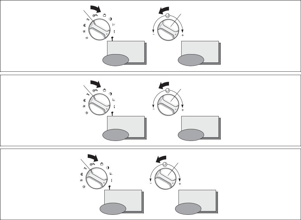
4.1 Betriebsart wählen
Mit dem Betriebsartenschalter (7, vordere Klappseite) können Sie die Betriebsweise Ihrer Anlage einstellen.
●Stellung „Programm“  In dieser Stellung
wird die Raumtemperatur vom eingegeben Programm geregelt. Während der Heizzeiten wird die Temperatur nach der am TagTemperaturwähler (1) eingestellten Temperatur geregelt, während der Absenkphase nach der AbsenkTemperatur.
●Stellung „Heizen“ 


In dieser Stellung wird die Raumtemperatur ständig nach der Temperatur geregelt, die am Tag-Temperatur-
wähler (1) eingestellt ist. Im Display erscheint 

 . Die Programmierung der Schaltuhr wird nicht berücksichtigt.
●Stellung „Absenken“  .
.
In dieser Stellung wird die Raumtemperatur ständig nach der Absenk-
Temperatur geregelt. Im Display erscheint  . Die Programmierung der Schaltuhr wird nicht berücksichtigt. Werkseitig ist die Absenkung auf 15 °C eingestellt.
GB
4 Basic settings
4.1 Choose the operating mode
The operating mode switch (7, front folding page) allows you to set the control for your particular needs. After a certain time — the length of which depends on your property and outside weather conditions — the selected room temperature will be reached.
●Position “Program“
The room temperature is controlled by the programmed settings.
During warm-up periods, the temperature is controlled by means of the day-temperature selector (1) setting, and by the reduction temperature during the reduction phase.
●Position “Heating” 


The room temperature is constantly
adjusted to the set day temperature. The display shows 

 .
.
Any programming is overridden.
●Position “Night setting” 
With this setting the room temperature
is constantly set at the night temperature. The display shows  . Any programming is
overridden. The factory setting for this mode is 15 °C.
FR
4 Les réglages de base
4.1 Choisir le mode de fonctionnement
Avec le commutateur de modes de fonctionnement (7, clapet frontal), vous pouvez adapter le mode de fonctionnement de votre installation à vos besoins. La température ambiante souhaitée est atteinte progressivement, la durée nécessaire dépendant de votre bâtiment et de la température extérieure.
●Position «Programme» 
Avec ce réglage, la température ambiante est réglée en fonction des données programmées. Pendant les périodes de chauffage, la température est régulée selon la température paramétrée sur le sélecteur de température jour (1), pendant la phase de baisse d’après la température d’abaissement.
●Position «Chauffage» 


Avec ce réglage, la température ambiante est constamment réglée en fonction de la température définie
avec le sélecteur de température jour. Le symbole 


 apparaît à l’écran. La programmation de la minuterie n’est pas prise en considération.
●Position «Abaissement» 
Avec ce réglage, la température de la pièce est constamment réglée en fonc-
tion de la température nocturne. Le symbole  apparaît à l’écran. La programmation de la minuterie n’est pas prise en considération. L’abaissement est réglé sur 15 °C par le constructeur.
13
4
3
2
1
VRC_VC2_009/0
4
3
2
1
VRC_VC2_009/0
4
3
2
1
VRC_VC2_009/0
14

4.2 Landessprache wählen
Der Regler wird werkseitig in der Landessprache „Deutsch“ bzw. „Spanisch“ ausgeliefert. Die Einstellung Ihrer Landessprache hat Ihr Installateur bei der Erstinbetriebnahme vorgenommen. Im Normalfall ist keine Änderung mehr erforderlich. Wollen Sie die Einstellung doch einmal ändern gehen Sie bitte wie folgt vor:
●Klappen Sie den Gerätedeckel (5) auf.
●Drehen Sie den Schalter (4) auf das Symbol  .
.
Im Display erscheint die
„internationale Länderkennung“ und der Schriftzug „Sprache“ in der jeweiligen Landessprache.
●Drehen Sie nun den Einsteller (3) nach rechts oder links und wählen Sie die gewünschte Sprache.
●Schließen Sie den Gerätedeckel (5).
Die Einstellung wird automatisch gespeichert. Sie müssen diese also nicht mehr bestätigen.
4.2 Choose a language
The control is pre-set by the factory to «German”. The re-setting to the language required (English, French, …) has already been done by your installer when the control was commissioned. Normally it is not necessary to re-set anything again. Should you wish to re-set the language yourself please proceed as follows:
●Open the control cover (5).
●Turn the switch (4) to symbol  .
.
The display shows the flashing writing “International Country-Identification” and the text message “Language“ in the corresponding language.
●Now turn the setting switch (3) left or right and choose die appropriate language.
●Close the control cover (5).
Your setting is automatically saved. You do not need to confirm your choice.
FR
4.2 Choix de la langue
Le régulateur est livré avec réglage sur la langue allemande. C’est votre installateur qui a effectué le réglage sur la langue requise (anglais, français, …) lors de la première mise en service. Normalement, aucune modification n’est plus nécessaire.
Si vous désirez cependant modifier le réglage, veuillez procéder comme suit:
●Ouvrez le couvercle (5).
●Placez le commutateur (4) sur le symbole  .
.
L’inscription „Désignation internationale des pays“ et l’inscription „Langue“ dans la langue nationale apparaît à l’écran et clignote.
●Tournez maintenant le sélecteur (3) vers la droite ou vers la gauche et choisissez la langue.
Le réglage est mémorisé automatiquement. Vous n’êtes donc plus obligé(e) de le confirmer de nouveau.
15

|
4 |
3 |
3 |
3 |
|
2 |
|||
|
1 |
|||
|
VRC-VC2_011/0 |
|||
|
4 |
3 |
3 |
3 |
|
2 |
|||
|
1 |
|||
|
VRC_VC2_011/0 |
|||
|
4 |
3 |
3 |
3 |
|
2 |
|||
|
1 |
|||
|
VRC_VC2_011/0 |
|||
|
16 |

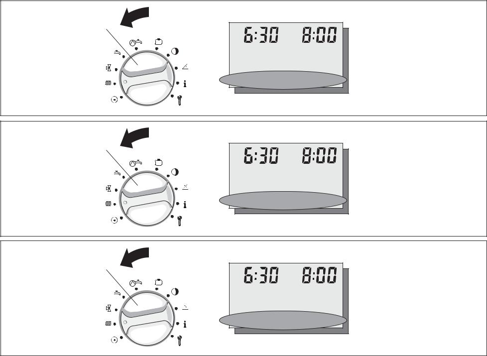
4.3 Uhrzeit und Wochentag einstellen
Wenn Ihr Gerät ist mit einem DCFEmpfänger ausgestattet ist, so synchronisiert dieser die Uhrzeit mit dem offiziellen deutschen Zeitsignal, wenn der Empfang möglich ist. Die Uhrzeit Ihres Regelgerätes stellt sich automatisch ein. Das gilt auch für die Umstellung von Sommerauf Winterzeit und umgekehrt. Müssen Sie Uhrzeit oder Wochentag jedoch einmal ändern gehen Sie bitte wie folgt vor:
●Klappen Sie den Gerätedeckel (5) auf.
●Drehen Sie den Schalter (4) auf das Symbol  .
.
Im Display erscheint eine blinkende Uhrzeit und der Schriftzug „Uhrzeit“.
●Drehen Sie nun den Einsteller (3)
—nach links, um die Uhrzeit zurückzustellen
—nach rechts, um die Uhrzeit vorzustellen.
●Drücken Sie den Einsteller (3).
Im Display erscheint ein blinkender Wochentag mit dem Schriftzug
„Wochentag“.
●Nehmen Sie die Einstellung wie bei der Uhrzeit beschrieben für den Wochentag vor.
Uhrzeit und Datum werden automatisch gespeichert. Sie müssen die neuen Werte also nicht bestätigen.
4.2 Date and time setting
(The DCF receiver system is not currently available in the UK)
If your control is fitted with a DCF receiver, the time for your thermostat will automatically adjusted and synchronised with the German standard time — if the signals can be received. This is also the case for changing from summer to winter time or vice versa.
Should you, however, need to adjust either time or date manually please proceed as follows:
●Open the control cover (5)
●Turn switch (4) to symbol  .
.
The display shows a flashing time and the word “Time“ next to it.
●Now turn the knob (3)
—to the left to adjust time backwards
—to the right to adjust time forward
●Press the knob (3)
The display shows a flashing day with the wording “Day“.
●Follow the same steps as for time also for day adjusting.
The new time and date are automatically saved, there is no need to confirm the new setting.
4.3 Réglage de l’heure et du jour
Si votre appareil est équipé d’un récepteur DCF (pas en France), l’heure de votre régulateur est règlé automatiquement. Il est synchronisé avec l’heure de l’horloge officielle allemande quand la réception est possible. Ceci vaut également pour le passage de l’heure d’été à l’heure d’hiver et inversement.
Si vous devez modifier l’heure ou le jour, veuillez procéder comme suit:
●Ouvrez le couvercle de l’appareil (5).
●Placez le commutateur (4) sur le
symbole  .
.
A l’écran, l’inscription «Heure» et l’heure apparaissent ; l’heure clignote.
●Tournez maintenant le sélecteur (3)
—vers la gauche, pour retarder l’horloge
—vers la droite, pour faire avancer l’horloge.
●Appuyez sur le sélecteur (3). A l’écran, l’inscription «Jour»
apparaît et le nom d’un des jours de la semaine clignote.
●Effectuez le réglage du jour de la semaine comme celui de l’heure.
L’heure et le jour sont mémorisés automatiquement. Vous n’êtes donc pas obligé(e) de confirmer les nouvelles valeurs.
17
|
3 |
°C |
3 |
°C |
|
&! |
&! |
||
|
#$% ‘ |
#$% ‘ |
|
VRC-VC2_008/0 |
|||||
|
4 |
°C |
3 |
°C |
3 |
°C |
|
2 |
|||||
|
1 |
! |
! |
! |
||
|
» « |
» « |
» « |
|||
|
VRC-VC2_008/0 |
|
4 |
°C |
3 |
°C |
3 |
°C |
|
2 |
|||||
|
1 |
! |
! |
! |
||
|
#$%% |
#$%% |
#$%% |
|||
|
18 |
VRC-VC2_008/0 |
||||

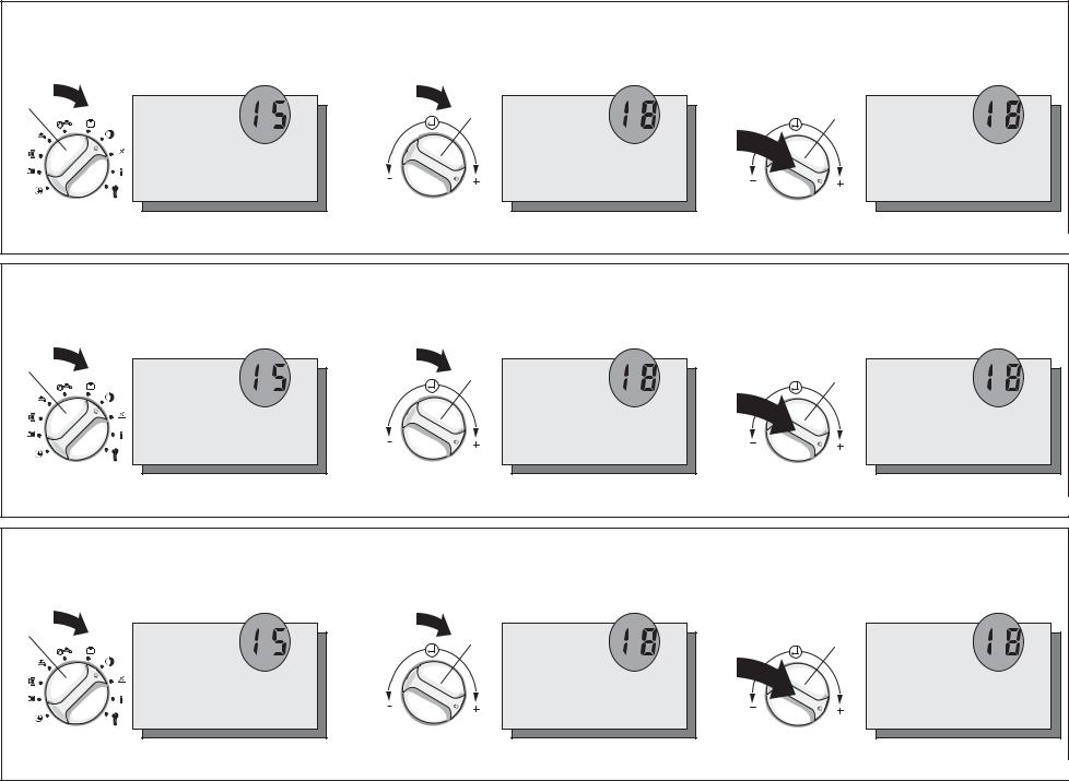
4.4 Absenktemperatur einstellen
●Klappen Sie den Gerätedeckel (5) auf.
●Drehen Sie den Funktionsartenschalter (4) auf das Symbol  .
.
Im Display erscheint eine blinkende 15 und die Anzeige „HK 1“ und „Absenktemp“.
●Drehen Sie nun den Einsteller (3)
—nach links, um die Absenktemperatur zu verringern
—nach rechts, um die Absenktemperatur zu erhöhen.
Der Wert wird automatisch gespeichert. Sie müssen den neuen Wert also nicht bestätigen.
Die Absenk-Temperatur kann in einem Bereich von 5 °C bis 20 °C verstellt werden.
Die Einstellung der Absenktemperatur auf 0°C empfiehlt sich nur bei längerer Abwesenheit, da sie nur den Frostschutz der Anlage sicherstellt.
●Zur Einstellung der Absenk-Temperatur für den Heizkreis 2 drücken Sie auf den „Einsteller“ (3), um den Heizkreis 2 auszuwählen.
Im Display erscheint eine blinkende 15 und die Anzeige „HK 2“ und „Absenktemp“.
Stellen Sie die Absenk-Temperatur ein wie oben beschrieben.
4.4 Adjusting night temperature
●Open the control cover (5)
●Turn switch (4) to symbol 
The display shows a flashing 15 and the words “HC1“ and “Min. Temp.“ next to it.
●Now turn the knob (3)
—to the left to decrease the temperature
—to the right to increase the temperature.
The new temperature is automatically saved, there is no need to confirm the new setting.
The reduction temperature can be adjusted within a range of 5 °C to 20 °C.
The reduction temperature should only be set to 0 °C during long absences, as it ensures only that the system will be protected from frost.
●To set the reduction temperature for heating circuit 2, press the “Adjuster“ (3) to select heating circuit 2.
The display shows a flashing 15 and the words “HC 2“ and “Min. Temp.“ next to it.
Set the reduction temperature as described above.
FR
4.4 Régler la température d’abaissement
●Ouvrez le couvercle de l’appareil (5).
●Placez le commutateur (4) sur le symbole  .
.
Le nombre 15 et les incriptions „CC 1“ et „Abaissement“ apparaisent à l’écran et le 15 clignote.
●Tournez maintenant l’ajusteur (3)
—vers la gauche, pour réduire la température d’abaissement
—vers la droite, pour faire augmenter la température d’abaissement
La valeur est mémorisée automatiquement. Vous n’êtes donc pas obligé(e) de confirmer les nouvelles valeurs.
La température d’abaissement peut être réglée dans une plage comprise entre 5 °C et 20 °C. Le paramétrage de la température d’abaissement à 0 °C est recommandé uniquement en cas d’absence prolongée afin de protéger l’installation du gel.
●Pour le paramétrage de la température d’abaissement du circuit de chauffage 2, pressez le sélecteur (3), afin de sélectionner le circuit de chauffage 2.
Le nombre 15 et les incriptions „CC 2“ et „Abaissement“ apparaisent à l’écran et le 15 clignote.
Paramétrez la température d’abaissement tel que décrit ci-dessus.
19
|
Vorlauftemperatur |
Heizkurven |
|||||||||||||||||
|
Advance flow temp. |
Heating curves |
|||||||||||||||||
|
Température aller |
Courbes de chauffage |
|||||||||||||||||
|
90 |
4.0 |
3.5 |
3.0 |
2.5 |
2.0 |
|||||||||||||
|
80 |
1.5 |
|||||||||||||||||
|
70 |
1.2 |
|||||||||||||||||
|
1.0 |
||||||||||||||||||
|
60 |
0.6 |
|||||||||||||||||
|
50 |
||||||||||||||||||
|
40 |
0.2 |
|||||||||||||||||
|
30 |
||||||||||||||||||
|
2020 |
||||||||||||||||||
|
15 |
10 |
5 |
0 |
– 5 |
– 10 |
– 15 |
– 20 |
|||||||||||
|
Außentemperatur |
||||||||||||||||||
|
Outside temperature |
||||||||||||||||||
|
Température extérieure |
VRC-VC2_019/0 |
|||||||||||||||||
4
3
2
|
! |
! |
|||||||||||
|
» ) |
» ) |
|||||||||||
|
3 |
3 |
|||||||||||
|
( |
( |
|||||||
|
» ) |
» ) |
VRC-VC2_010/1
4
3
2
|
&! |
&! |
|||||||||||||||||||
|
+,& ) |
+,& ) |
|||||||||||||||||||
|
3 |
3 |
|||||||||||||||||||
|
&( |
&( |
||||
|
+,& ) |
+,& ) |
||||
VRC-VC2_010/1
4
3
2
|
! |
! |
|||||||||||||||
|
$** |
$** |
|||||||||||||||
|
3 |
3 |
|||||||||||||||
|
( |
( |
||||
|
$** |
$** |
||||
VRC-VC2_010/1
20
![]()
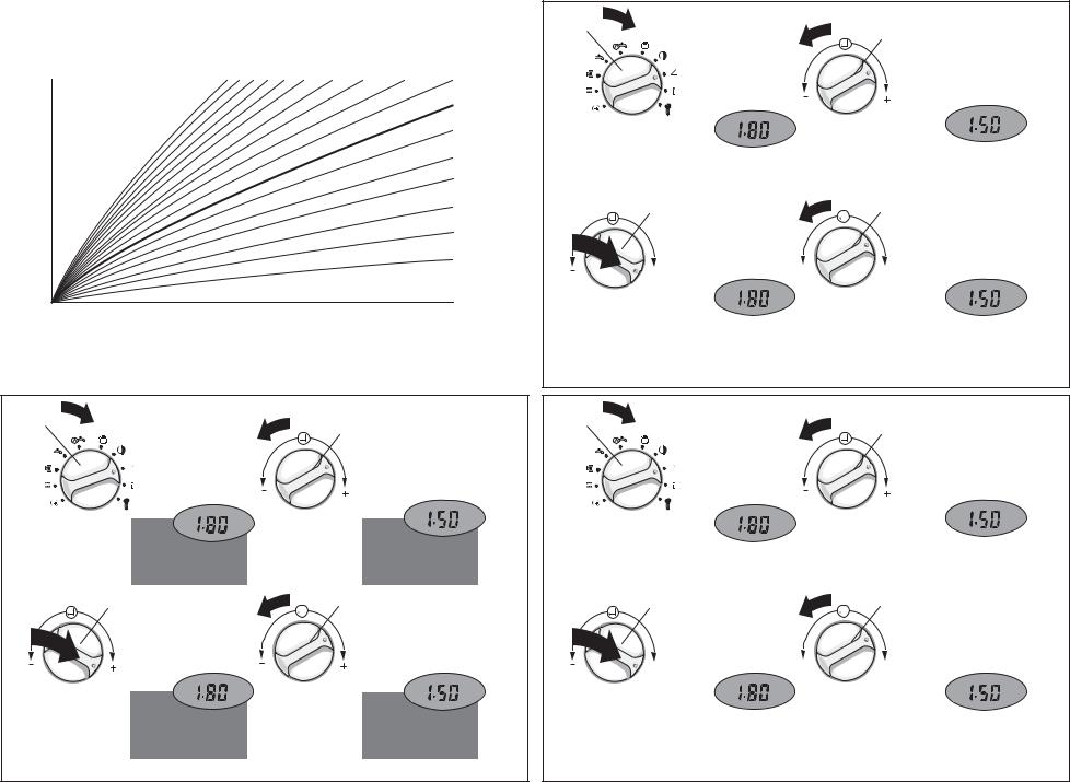
4.5 Heizkurve einstellen
Die Heizkurve beschreibt die Abhänigkeit der erforderlichen Vorlauftemperatur von der Außentemperatur.
Die Einstellung der Heizkurve hat Ihr Installateur bei der Erstinbetriebnahme vorgenommen. Im Normalfall ist keine Änderung mehr erforderlich.
Falls bei niedrigen Außentemperaturen trotz voll geöffneter Thermostatventile und geschlossener Türen und Fenster die gewünschte Raumtemperatur nicht erreicht wird, sollten Sie die Heizkurve korrigieren. Gehen Sie bitte wie folgt vor:
●Klappen Sie den Gerätedeckel (5) auf.
●Drehen Sie den Schalter (4) auf das Symbol 
 .
.
Im Display erscheint eine blinkende Zahl und der Schriftzug „Hz-Kurve“ und „HK 1“.
●Wählen Sie den Heizkreis aus Heizkreis 1: ist bereits aktiv
für Heizkreis 2 Einsteller (3) drücken.
●Drehen Sie nun den Einsteller (3)
—nach links, um den Wert zu verringern
—nach rechts, um den Wert zu vergrößern.
Der neue Wert wird automatisch gespeichert. Sie müssen ihn also nicht mehr bestätigen.
4.5 Setting the heating curve
The heating curve has been set by your installer when he commissioned your thermostat. Normally it is not necessary to change this setting. Should you, however, need to re-set the heating curve, proceed as follows:
●Open the control cover (5).
●Turn switch (4) to symbol 
 .
.
The display shows a flashing number and the word “Heat. Curve“ and
„HC1“.
●Turn knob (3)
—to the left, to decrease the value
—to the right to increase the value
The heating curve must be set correctly to match the design requirements of the heating system. e.g. 80°C flow, 60°C return at -1°C outside temperature, the heat curve parameter should be set around 2.6 to 2.8 to satisfy the heating demand.
●To set the heating curve for heating circuit 2, press the “Adjuster“ (3) to select heating circuit 2.
The display shows a flashing 15 and the words “HC 2“ and “Heat. Curve“ next to it.
Set the heating curve as described above.
The new value is saved automatically, there is no need to confirm the new setting.
4.5 Réglage de la courbe de chauffage
Le réglage de la courbe de chauffage a été effectué par votre installateur lors de la première mise en service. Normalement, aucune modification n’est plus nécessaire. Si vous désirez cependant modifier le réglage de la courbe de chauffage, veuillez procéder comme suit:
●Ouvrez le couvercle (5) de l’appareil.
●Placez le commutateur (4) sur le symbol 
 .
.
Un nombre qui clignote et l’inscription
«Courbe chauf» et „CC1“ apparaissent à l’écran.
●Tournez maintenant le sélecteur (3)
—vers la gauche, pour réduire la valeur,
—vers la droite, pour faire augmenter la valeur.
●Pour le paramétrage de la courbe de chauffage du circuit 2, pressez le sélecteur (3), afin de sélectionner le circuit de chauffage 2.
Le nombre 15 et les incriptions „CC 2“ et „Abaissement“ apparaisent à l’écran et le 15 clignote.
Paramétrez la courbe de chauffagel que décrit ci-dessus.
La nouvelle valeur est mémorisée automatiquement. Vous n’êtes donc plus obligé(e) de la confirmer de nouveau.
21
|
HK1 |
HK2 |
Warmwasser- |
Zirkulations- |
HK1 |
HK2 |
HK1 |
HK2 |
||
|
Anzeige |
Heizzeiten |
Heizzeiten |
zeiten |
zeiten |
Nachttemp. |
Nachttemp. |
Heizkurve |
Heizkurve |
|
|
Display |
HC1 Heating |
HC2 Heating |
Hot water |
Circulation |
HC1 Night |
HC2 Night |
HC1 Heating |
HC1 Heating |
|
|
Affichage |
settings |
settings |
settings |
settings |
temperature |
temperature |
curve |
curve |
|
|
CC1 Périodes |
CC2 Périodes |
Périodes |
Périodes |
CC1Température |
CC2Température |
CC1 Courbe |
CC2 Courbe |
||
|
de chauffage |
de chauffage |
E.C.S. |
de circulation |
d’abaissement |
d’abaissement |
de chauffage |
de chauffage |
||
|
Allgemein |
15°C |
15°C |
1,2 |
1,2 |
|||||
|
General |
|||||||||
|
En général |
|||||||||
|
Mo bis Fr |
06:00 — 22:00 |
06:00 — 22:00 |
06:00 — 22:00 |
06:00 — 22:00 |
|||||
|
Mo — Fr |
|||||||||
|
Du lu au ve |
|||||||||
|
Sa |
07:30 — 23:30 |
07:30 — 23:30 |
07:30 — 23:30 |
07:30 — 23:30 |
|||||
|
Sa |
|||||||||
|
Sa |
|||||||||
|
So |
07:30 — 22:00 |
07:30 — 22:00 |
07:30 — 22:00 |
07:30 — 22:00 |
|||||
|
Su |
|||||||||
|
Di |
|||||||||
22

DE
5 Zeitprogramme einstellen
Das Regelgerät kann zwei Heizkreise steuern.
Darüber hinaus kann die Warmwasserbereitung und die Zirkulationspumpe gesteuert werden.
5.1 Werkseitige Einstellungen
Werkseitig sind sinnvolle Zeitprogramme für die einzelnen Kreise voreingestellt. Der nebenstehenden Tabelle können Sie die werkseitigen Einstellungen entnehmen.
Sind Sie mit den Einstellungen zufrieden brauchen Sie keine weiteren Änderungen mehr vorzunehmen.
Wollen Sie die eine oder andere Einstellung ändern, gehen Sie bitte in das entsprechende Kapitel der Bedienungsanleitung.
Tipp!
Bei geänderten Einstellungen ist es sinnvoll, die Daten in die freien Felder der nebenstehenden Tabelle einzutragen.
GB
5 Setting the timer programs
The system can control two heating circuits – plus the hot-water supply and the circulation pump.
5.1 Pre-set values
The timer programs for the individual circuits are factory adjusted to normal default settings. The opposite table shows all values which already have been preset. If you are happy with those settings there is no need for any further action.
Should you wish to change the one or other settings please look at the respective chapter in the instructions.
HINT !
You might find it helpful to enter any changed settings into the empty boxes of the table opposite.
FR
5Paramétrage des programmes temps
La régulation peut commander deux circuits de chauffage.
Il peut en outre piloter la préparation d’eau chaude et la pompe de recyclage.
5.1 Réglages du constructeur
Des programmes temps recommandés pour chacun des circuits sont préréglés en usine.
Le tableau ci-contre donne les réglages du constructeur.
Si ces réglages vous conviennent, aucune modification n’est nécessaire.
Si vous désirez faire telle ou telle modification, veuillez vous reporter au chapitre correspondant des instructions de service.
UN «TUYAU»!
En cas de modification des réglages, il peut être utile de noter les diverses données et de les inscrire dans les cases vides du tableau ci-contre
23

|
, |
, |
, |
|||||||||||
|
% |
! |
% |
( |
% |
— |
||||||||
VRC_VC_135/1
|
, |
, |
, |
|||||||||||
|
. |
! |
. |
( |
. |
— |
||||||||
VRC_VC_135/1
|
,/ |
,/ |
,/ |
|||||||||||
|
0 « |
! |
0 « |
( |
0 « |
— |
||||||||
VRC_VC_135/1
24

DE
5.2 Übersicht Zeitprogramme
Für jeden Heizkreis, sowie für die Warmwasserbereitung können Sie bis zu drei Heizzeiten pro Tag programmieren, die in sogenannten Fenstern angezeigt werden, z. B.
Fenster 1:
Heizung an: 5:30
Heizung aus: 8:00
Fenster 2:
Heizung an: 11:30
Heizung aus: 13:45
Fenster 3:
Heizung an: 18:00
Heizung aus: 22:30
Die Heizzeiten können Sie für die Blöcke
Montag bis Sonntag (Mo-So)
Montag bis Freitag (Mo-Fr)
Samstag bis Sonntag (Sa-So)
oder für einzelne Tage (Mo, Di, Mi, Do, Fr, Sa, So) eingeben.
Die Ansteuerung der Zirkulationspumpe erfolgt ebenfalls über maximal drei Zeitfenster pro Tag.
5.2 Overview
You can program each heating circuit and the hot water supply to activate up to three times a day, using a “windows“- type system. For example,
Programme 1:
Heating start: 5:30
Heating stop: 8:00
Programme 2:
Heating start: 11:30
Heating stop: 13:45
Programme 3:
Heating start: 18:00
Heating stop: 22:30
These heating periods can be entered for sets of days, like
Monday to Sunday
Monday to Friday
Saturday to Sunday
or individual days (Mo, Tu, We, Th, Fr, Sa, Su).
The activation of the circulation pump is also carried out via a maximum of three “time windows“ per day.
The secondary circulation pump function requires a additional PCB accessory for the UK market. This is available from Vaillant.
5.2 Présentation générale
Pour chaque circuit de chauffage ainsi que pour la préparation d’eau chaude, vous pouvez programmer jusqu’à trois périodes de chauffage par jour qui seront affichées dans lesdites fenêtres, par ex.
Fenêtre 1:
Mise en marche du chauffage: 5:30
Arrêt du chauffage: 8:00
Fenêtre 2:
Mise en marche du chauffage: 11:30
Arrêt du chauffage: 13:45
Fenêtre 3:
Mise en marche du chauffage: 18:00
Arrêt du chauffage: 22:30
Vous pouvez définir ces périodes de chauffage pour les blocs
Lundi à dimanche (Lu — Di)
Lundi à vendredi (Lu — Ve)
Samedi à dimanche (Sa — Di)
ou pour des jours isolés (Lu, Ma, Me, Je, Ve, Sa, Di).
Le pilotage de la pompe de recyclage s’effectue également par trois fenêtres de temps maximum par jour.
25
4
VRC-VC2_013/0
4
VRC-VC2_013/0
4
VRC-VC2_013/0
26
 Loading…
Page 1 — Sa — 15°C
PartySa — 15°C°CVRC-VCC+10+2+3-1-2-384+420BEDIENUNGS- UND MONTAGEANLEITUNGOPERATING AND INSTALLATION INSTRUCTIONSÐÐÓÓÊÊÎÎÂÂÎÎÄÄÑÑÒÒÂÂÎÎ ÏÏÎÎ ÓÓÑÑÒÒ
Page 2
DE GB RUS102.2 LüftenStellen Sie den Betriebsartenschalter (7,vordere Klappseite) während des Lüftensauf Absenken . Damit vermeiden Sieeine unnötige
Page 3
DE GB RUS112.4 Einmalige Ladung für Warmwas-serIhr Gerät ist mit einer Funktion zur ein-maligen Ladung des Speicherwassersausgestattet. Diese erlaubt
Page 4 — Display, Übersicht
DE GB RUS123 Energiespartipps☞Stellen Sie die Raumtemperatur nurso hoch ein, daß diese für Ihr Beha-glich-keitsempfinden gerade aus-reicht. Jedes Grad
Page 5
DE GB RUS134 Grundeinstellungen4.1 Betriebsart wählenMit dem Betriebsartenschalter (7, vordereKlappseite) können Sie die BetriebsweiseIhrer Anlage ein
Page 6 — Display, Overview
2143VRC_VC2_009/0Íåì. ÿçûêÀíãë. ÿçûê2143VRC_VC2_009/0Íåì. ÿçûêÀíãë. ÿçûê2143VRC_VC2_009/0Íåì. ÿçûêÔðàíö. ÿçûê14
Page 7 — ДДииссппллеейй::
DE GB RUS154.2 Landessprache wählen☞Der Regler wird werkseitig in derLandessprache Deutsch bzw. Span-isch ausgeliefert. Die Einstellung Ih-rer Lan
Page 8 — 1 Device description
332143VRC-VC2_011/0SoUhrzeitSoUhrzeitSoWochentagMiWochentag332143VRC_VC2_011/0SuTimeSuTimeSuDayWeDay332143VRC_VC2_011/0ÂñÂðåìÿÂñÂðåìÿÂñ Äåíü íåäåëèÑð
Page 9 — 22 ООббссллуужжииввааннииее
DE GB RUS174.3 Uhrzeit und Wochentag einstellenWenn Ihr Gerät ist mit einem DCF-Emp-fänger ausgestattet ist, so synchronisiertdieser die Uhrzeit mit d
Page 10 — DE GB RUS
°C°C°C21433VRC-VC2_008/0HC1Min. Temp.HC1Min. Temp.HC1Min. Temp.°C°C°C21433VRC-VC2_008/0ÍÊ1Ïîíèæåííàÿ òåìïåðàòóðà ÍÊ1Ïîíèæåííàÿ òåìïåðàòóðà ÍÊ1Ïîíèæåíí
Page 11
DE GB RUS194.4 Absenktemperatur einstellen●Klappen Sie den Gerätedeckel (5) auf.●Drehen Sie den Funktionsartenschal-ter (4) auf das Symbol .Im Displa
Page 12 — 3 Energy saving hints
DE GB RUS2Verehrte Kundin, geehrter Kunde!Mit dem Vaillant Regelgerät VRC 420haben Sie ein Spitzenprodukt aus demHause Vaillant erworben. Um alle Vort
Page 13 — 4 Basic settings
321433VRC-VC2_010/1HC2Heat. CurveHC1Heat. CurveHC1Heat. CurveHC2Heat. Curve321433VRC-VC2_010/1ÍÊ2Êðèâàÿ îòîïëåíèÿ ÍÊ1Êðèâàÿ îòîïëåíèÿÍÊ1Êðèâàÿ îòîïëåí
Page 14 — VRC_VC2_009/0
DE GB RUS214.5 Heizkurve einstellenDie Heizkurve beschreibt die Abhänigkeitder erforderlichen Vorlauftemperatur vonder Außentemperatur. Die Einstellun
Page 15
22HK1 HK2 Warmwasser- Zirkulations- HK1 HK2 HK1 HK2Anzeige Heizzeiten Heizzeiten zeiten zeiten Nachttemp. Nachttemp. Heizkurve HeizkurveDisplay HC1 He
Page 16 — VRC_VC2_011/0
DE GB RUS235 Zeitprogramme einstellenDas Regelgerät kann zwei Heizkreisesteuern. Darüber hinaus kann die Warmwasser-bereitung und die Zirkulationspump
Page 17
VRC_VC_135/1Mo-FrFenster 1Mo-FrFenster 2Mo-FrFenster 3VRC_VC_135/1Mo-FrProgramme 1Mo-FrProgramme 2Mo-FrProgramme 3VRC_VC_135/1Ïí.-Ïò.Îêíî 1Ïí.-Ïò.Îêíî
Page 18 — Ïîíèæåííàÿ òåìïåðàòóðà
DE GB RUS255.2 Übersicht ZeitprogrammeFür jeden Heizkreis, sowie für die Warm-wasserbereitung können Sie bis zu dreiHeizzeiten pro Tag programmieren,
Page 19
214VRC-VC2_013/0Mo-FrFenster 1214VRC-VC2_013/0Mo-FrProgramme 1214VRC-VC2_013/0Ïí.-Ïò.Îêíî 126
Page 20 — VRC-VC2_019/0
DE GB RUS275.3 Heizkreis wählen●Klappen Sie den Gerätedeckel (5)auf.●Drehen Sie den Schalter (4) auffür Heizkreis 1 bzw.für Heizkreis 2. Im Display er
Page 21
3333VRC-VC2_015/0Mo-FrOn time 1Mo-FrOn time 1Mo-FrOff time 1Mo-FrOff time 13333VRC-VC2_015/0Ïí.-Ïò.Âêëþ÷åíèå 1Ïí.-Ïò.Âêëþ÷åíèå 1Ïí.-Ïò.Âûêëþ÷åíèå 1Ïí.
Page 22 — 15°C 15°C 1,2 1,2
DE GB RUS295.4 Heizzeiten einstellen (Fortset-zung)●Drücken Sie den Einsteller (3) bis dielinke Uhrzeit blinkt.Im Display steht in der Klarschriftzeil
Page 24 — VRC_VC_135/1
3333VRC-VC2_016/0Ïí.-Ïò.Îêíî 1Ïí.-Ïò.Îêíî 2Ïí.-Ïò.Âêëþ÷åíèå 2Ïí.-Ïò.Âêëþ÷åíèå 23333VRC-VC2_016/0Mo-FrProgramme 1Mo-FrProgramme 2Mo-FrOn time 2Mo-FrOn
Page 25
DE GB RUS315.4 Heizzeiten einstellen (Fortset-zung)Nun soll das zweite Zeitfenster program-miert werden:●Drücken Sie den Einsteller (3) bis dieZeile
Page 26 — VRC-VC2_013/0
3333VRC-VC2_017/0Mo-FrFenster 1Mo-FrWochentag 1Sa-SoWochentag 1Sa-SoBeginn 13333VRC-VC2_017/0Mo-FrProgramme 1Mo-FrDay 1Sa-SuDay 1Sa-SuOn time 13333VRC
Page 27
DE GB RUS335.4 Heizzeiten einstellen (Fortset-zung)Jetzt fehlen nur noch die Zeiten für dasWochenende:●Drücken Sie den Einsteller (3) bis dieZeile Fe
Page 28 — VRC-VC2_015/0
345.5 Warmwasserzeiten einstellenMit Ihrem Regelgerät können Sie bis zudrei Warmwasserzeiten pro Tag pro-grammieren. Der Schalter 4 unter demGerätedec
Page 29
DE GB RUS355.6 Zirkulationszeiten einstellenAls Zubehör zum Gerät ist eine Zirkula-tionspumpe erhältlich. Ist Ihre Anlage mit einer Zirkulationslei-tu
Page 30 — VRC-VC2_016/0
321433VRC-VC2_014/0Âñ.Íà÷àëî îòïóñêàÂñ.Íà÷àëî îòïóñêàÂñ.Ïðîäîëæèòåëüíîñòüîòïóñêà Âñ.Ïðîäîëæèòåëüíîñòüîòïóñêà 321433VRC-VC2_014/0SuHoliday StartThHolid
Page 31
DE GB RUS375.7 FerienprogrammIhr Gerät hat ein Ferienprogramm, mit demSie Heizung, Warmwasser und Zirkulationfür die Dauer Ihres Urlaubs abschalten od
Page 32 — VRC-VC2_017/0
38Sonderfunktionen Minimal Maximal Schrittweite WerkseinstellungSpecial functions Minimum Maximum Stepped Factory settingДДооппооллннииттееллььнныыее
Page 33
DE GB RUS396 SonderfunktionenDas Regelgerät verfügt über eine Reihevon Sonderfunktionen, die es ermögli-chen den Regler an die Heizungsanlageanzupasse
Page 34
Bedienelemente1 Tag-Temperaturwählerzur Einstellung der gewünschten Raumtemperatur.2 Partytaste/einmaliges Laden des Speicherszur vorübergehenden Absc
Page 35
40Sonderfunktionen Minimal Maximal Schrittweite WerkseinstellungSpecial functions Minimum Maximumn Stepped Factory settingДДооппооллннииттееллььнныыее
Page 36 — VRC-VC2_014/0
DE GB RUS41Raumtemperaturaufschaltung für HK 1und HK2Bei Wandmontage des Reglers kann dieRaumtemperatursteuerung aktiviert werden.Bei Abweichung der R
Page 37
42FrostschutzverzögerungUm bei gut gedämmten Häusern ein Dur-chlaufen der Heizung zu vermeiden, kannder Frostschutz von 0h bis 24h verzögertwerden. Na
Page 38
DE GB RUS43nicht von allen Geräten unterstützt, bitte les-en Sie in der entsprechenden Bedienungs-bzw. Installationsanleitung nach. Solangedas Heizger
Page 39 — 6 Special functions
DE GB RUS44Speicherladepumpe möglich. Bei Gerätenmit Vorrangumschaltventil muss die Einstel-lung auf aus (= 0) stehen☞Nur der Mischerkreis wird parall
Page 40 — (Temp. offset) for HC2
DE GB RUS45Zyklus 2 / ЦЦиикклл 22Tag Vorlaufsolltemperatur HK2ДДеенньь ЗЗааддааннннааяя ттееммппееррааттуурраа ппооддааюющщеейй ввооддыы ооттоопп
Page 41
46Display-Anzeige Bedeutung Einheit angezeigter WertППооккааззаанниияя ддииссппллееяя ЗЗннааччееннииее ЕЕддииннииццыы ППооккааззааннннооее ззннаачче
Page 42
DE GB RUS477 Info-AnzeigeDas Regelgerät ist mit einer Info-Anzeigeausgestattet. Diese ermöglicht es sich ver-schiedene wichtige Werte bzw. Einstellun-
Page 43
DE GB RUS488 FehlermeldungenIm Display des Gerätes können im Stö-rungsfall folgende Fehlermeldungenerscheinen:Störung:Das Heizgerät hat eine Störung
Page 44
DE GB RUS499 FrostschutzIhr Regelgerät ist mit einer Frostschutz-funktion ausgestattet. Sinkt die Außen-temperatur unter einen Wert von +3 °Cwird auto
Page 45 — ЦЦиикклл 11
DE GB RUS5INHALT SeiteBedienungsanleitung . . . . . .31 Geräteübersicht . . . . . . . . . . . .3,821 Gerätebeschreibung . . . . . . . . . . .82 Bedie
Page 46
DE GB RUS5011 TelefonfernsteuerungDie Heizungsanlage kann über eine Kom-munikationsschnittstelle (Zubehör) ferngest-euert werden. Gesteuert werden unt
Page 47 — 7 Display of information
DE GB RUS5113 WerksgarantieWerksgarantie gewähren wir nur bei In-stallation durch einen anerkannten Fach-handwerksbetrieb.Dem Eigentümer des Gerätes r
Page 48 — 8 Error messages
52Для Беларуси, Молдовы, Украины:Выполнение гарантийных обязательств, предусмотренныхдействующим законодательством той местности, где былприобретён ап
Page 49
DE GB RUS53MontageanleitungSeite1 Allgemeines . . . . . . . . . . . . . . . .542 Regelgerät montieren . . . . . . . . .552.1 Wandmontage . . . . . .
Page 50
541 AllgemeinesDie Montage, der elektrischeAnschluß, die Einstellungenim Gerät sowie die Erstinbet-rieb-nahme dürfen nur durcheinen anerkannten Fach-h
Page 51 — 13 Manufacturers Warranty
DE GB RUS552 Regelgerät montierenDas Regelgerät kann direkt im Schalt-kasten des Heizgerätes oder als Fernbe-dienungsgerät an einer Wand ange-bracht w
Page 52
5612+-337894VRC_VC_054/0VRC_VC2_021/0
Page 53 — Installation instructions
DE GB RUS572.1 Wandmontage (Fortsetzung)Verlegen Sie die elektrischen Leitungenzum Heizgerät zweckmäßigerweise schonvor Anbringen des Regelgerätes. Ge
Page 54 — 1 General
58789DCFRFAF 0 078 9X8VRC 692VRC 693VRC 420ϑϑVRC-VC2_048/0Schaltkasten HeizgerätBoiler electronics control boxРРаассппррееддееллииттееллььннааяя ккоо
Page 55 — 2 Installing the thermostat
DE GB RUS592.2 Elektrischer AnschlußDer elektrische Anschluß darf nur von ei-nem anerkannten Fachhandwerksbetriebvorgenommen werden.Lebensgefahr durch
Page 56 — VRC_VC_054/0VRC_VC2_021/0
GB6Operating elements1 Day temperature selectorfor adjusting to required room temperature.2 Override/one-off filling of tankfor temporary deactivation
Page 57
60bar21 30PartySa — 15°C°CVRC-VCC+10+2+3-1-2-3+-+-343VRC-VC2_022/0
Page 58 — VRC-VC2_048/0
DE GB RUS612.3 Montage im GerätDie Montage im Gerät darf nur von ei-nem anerkannten Fachhandwerksbetriebvorgenommen werden.Lebensgefahr durch Stroms-c
Page 59
DE GB RUS622.3 Montage im Gerät (Fortsetzung)●Schließen Sie den Schaltkasten desHeizgerätes gemäß der Installation-sanleitung.●Schalten Sie die Stromz
Page 60 — VRC-VC2_022/0
DE GB RUS633 External sensor VRC 6933.1 Fitting locationThe external sensor should be attachedto the side of the building that corre-sponds to the ro
Page 61
64123489345678VRC_VC_158/0DCFRFAF 0 078 9X8693VRC-VC2_006/0Schaltkasten GerätBoiler electronics control boxРРаассппррееддееллииттееллььннааяя ккоорро
Page 62
DE GB RUS653.2 Montage des Außenfühlers●Entfernen Sie die Abdeckplatte (1) desGehäuses und befestigen Sie das Ge-häuse mit 2 Schrauben über den Be-fes
Page 63 — 3 Außenfühler VRC 693
664 DCF-EmpfängerBitte beachten Sie bei der Montage, dassdie Synchronisationszeit etwa 5 Minutenbeträgt, unter ungünstigen Umständenauch etwas länger
Page 64 — VRC-VC2_006/0
DE GB RUS67☞Vor dem Befestigen des DCF-Empfän-gers an der Gebäudewand sollte im-mer geprüft werden, ob an der vor-gesehenen Stelle auch ein ausrei-che
Page 65
684433125DCF0AFVRC_DCF_003ca 40 mm∅ 4,5 — 10 mmDCF0AFVRC_DCF_004
Page 66 — 44 DDCCFFппррииёёммнниикк
DE GB RUS694.2 Montage des DCF-EmpfängersGefahr der Durchfeuchtung vonWand und Gerät!Durch eine entsprechende Ka-belführung und sorgfältige Ar-beitswe
Page 67
RUS7ЭЭллееммееннттыы ууппррааввллеенниияя::1. Переключатель дневной температуры — служит для установкижелаемой температуры в помещении.2. Клавиша &qu
Page 68 — ∅ 4,5 — 10 mm
70DCF0AFDCFRFAF 0 0X8DCF0AFDCFRFAF 0 0X8VRC_VC_060/3VRC_VC_059/3Schaltkasten HeizgerätBoiler electronics control boxРРаассппррееддееллииттееллььннааяя
Page 69
DE GB RUS714.3 Verdrahtung des DCF-Empfängers●Verdrahten Sie die Anschlußklemmenentsprechend dem Anschlußschemagemäß der nebenstehenden Abbild-ungen.☞
Page 70 — VRC_VC_059/3
724NL NL N ZUAUFNL230 VNL230 VNLZPHK1HK2MischerM89 7RT 24V=21VF2N L N L N ZUAUFAUFN L230 V230 VN L230 V230 VN LZPHK1HK2MischerM89 7RT 24V=T 24V=21VF25
Page 71
DE GB RUS735 Mischermodul5.1 Montage der Anschlußbox Die vorbereiteten Langlöcher (5) imBoden der Zubehör-Anschlußboxdurchstechen. Anschlußbox mit d
Page 72 — VRC-VC2_003/1
74NL987RT 24V=230V~VF2987ZPMHK1HK2230V~NL NL230 V~NL NL230 V~N ZUAUFNLZPHK2HK1Mischer89 712 RT 24VVF2VRC-VC2_004/2Zirkulation-spumpeCirculationpumpННа
Page 73 — 5 Mixer module
DE GB RUS755.2 Verdrahtung des MischermodulsLebensgefahr durch Stroms-chlag an spannungsführendenAnschlüssen.Vor Arbeiten am Gerät dieStromzufuhr absc
Page 75
DE GB RUS776 ErstinbetriebnahmeDie erste Inbetriebnahme des Regel-gerätes mit der Heiz- und Brauchwasser-anlage sowie die ersten Eingaben ent-sprechen
Page 77 — 66 ППееррввыыйй ппуусскк
DE79Bedienelemente und Funktionen (Abbildung siehe Aufklappseite 82)1 Tag-TemperaturwählerZur Verstellung der Raum-Solltemperatur Seite 92 Partytast
Page 78 — VRC-VC2_005/1
DE GB RUS81 GerätebeschreibungDas Regelgerät ermöglicht die witterungs-geführte Vorlauftemperatur-Regelungzweier Heizkreise, eines Brennerkreisesund e
Page 79
GB80Operating elements and functions (figure see back folding page 82)1 Day temperature selectorRefer to page 9 for details of how to adjust the targe
Page 80
RUS81Органы управления и выполняемые функции (раскладка на стр. 82)11Переключатель дневной температуры — служит для установки желаемой температуры в п
Page 81
82PartySa — 15°C°CVRC-VCC+10+2+3-1-2-3122176534420VRC-VC2_020/0
Page 82
DE GB RUS83Appliance TypeTechnische Daten Technical specificationsТТееххннииччеессккииее ххааррааккттееррииссттииккииOperating voltagePower consumpti
Page 83
83 42 37 DE/GB/FR02 · 03/02 V · Änderungen vorbehalten — Subject to alteration — Sous réserve de modifications
Page 84
DE GB RUS92 BedienungDamit Ihr Heizgerät optimal arbeitet,stellen Sie den Betriebsartenschalter (7,vordere Klappseite) auf Programm .2.1 Raumtempera
2 docs – User Manuals, Help Guides and Specs – for the Vaillant VRC 420 product are present in our data base.
Tips for Finding Manuals:
This web-page provides a list of 2 accessible operating manuals and information books describing Vaillant VRC 420.
All manuals and instructions for Vaillant VRC 420 are introduced in an easy-to-use PDF format and may be gratuitously downloaded or looked through directly from the site.
The page offers the following types of manuals: Thermostat.
Helpful hints: While selecting a necessary guide for Vaillant VRC 420 one should pay special attention to the type of the document.
We try to supply you with the fullest possible set of papers we or our users are able to find. These may be overviews and specifications of the device, mounting and installing instructions, the unit operating rules and maintenance regulations and much more.
Haven’t found a required manual for your Vaillant VRC 420?
Check in a while. We update our guides collection and add new documents on a daily basis for you to be always able to find the very paper you need on our web-site. In case you own a directory or an instruction for Vaillant VRC 420, which is absent on our site, and you’d like to share it with the public, please send it to us as a scanned copy or a PDF file, and we’ll definitely place it on our page while providing your name as a supplier of the doc. Lots of our users will be grateful for your assistance!
| Document’s Content and Additional Information | Share Manual |
|---|---|
|
Vaillant VRC 420 Operating and installation instructions
Pages Preview: Document Transcription:
See Details |
|
|
Vaillant VRC 420 Operating and installation instructions
See Details |


![]() В данном разделе Вы найдете актуальные инструкции по продукции Vaillant в формате pdf.
В данном разделе Вы найдете актуальные инструкции по продукции Vaillant в формате pdf.
Настенные котлы atmoTEC и turboTEC
- atmoTEC и turboTEC Система подвода воздуха и отвода продуктов сгорания (1610 Кб)
- atmoTEC plus/pro Инструкция по монтажу (7410 Кб)
- atmoTEC и turboTEC plus/pro Инструкция по эксплуатации (1870 Кб)
- turboTEC plus/pro Инструкция по монтажу (5470 Кб)
Настенные котлы конденсационные ecoTEC plus малой мощности
- ecoTEC plus Инструкция по эксплуатации (1050 Кб)
- ecoTEC plus Инструкция по монтажу (5190 Кб)
- ecoTEC plus Система подвода воздуха и отвода продуктов сгорания (7750 Кб)
- ecoTEC plus Система дымоходов для каскадного подключения конденсационных котлов (960 Кб)
Настенные котлы конденсационные ecoTEC plus 466, 656
- ecoTEC VU 466 Инструкция по эксплуатации (1440 Кб)
- ecoTEC VU 466 Инструкция по монтажу (7040 Кб)
- ecoTEC VU 466 Каталог запчастей (610 Кб)
- ecoTEC VU 656 Инструкция по монтажу (9170 Кб)
- ecoTEC VU 656 Инструкция по эксплуатации (1770 Кб)
- ecoTEC VU/VUW 356 Инструкция по монтажу (2730 Кб)
- ecoTEC VU/VUW 356 Инструкция по эксплуатации (1770 Кб)
- ecoTEC Система дымоходов для каскадного подключения конденсационных котлов (2540 Кб)
- ecoTEC Система подвода воздуха и отвода продуктов сгорания (1700 Кб)
Напольные котлы atmoVIT
- atmoVIT Инструкция по монтажу (3860 Кб)
- atmoVIT Инструкция по эксплуатации (2490 Кб)
- atmoVIT Каталог запчастей (260 Кб)
Напольные котлы atmoVIT exclusiv
- atmoVIT exclusiv Инструкция по монтажу (4650 Кб)
- atmoVIT exclusiv Инструкция по эксплуатации (2490 Кб)
- atmoVIT exclusiv Каталог запчастей (420 Кб)
Напольные котлы atmoCRAFT
- atmoCRAFT Инструкция по монтажу (8210 Кб)
- atmoCRAFT Инструкция по эксплуатации (3290 Кб)
Напольные котлы ecoVIT
- ecoVIT Инструкция по монтажу (3900 Кб)
- ecoVIT Инструкция по эксплуатации (1350 Кб)
Напольные котлы ecoCOMPACT
- ecoCOMPACT Инструкция по эксплуатации (1190 Кб)
- ecoCOMPACT Инструкция по монтажу (4870 Кб)
- ecoCOMPACT Система подвода воздуха и отвода продуктов сгорания (1840 Кб)
- ecoCOMPACT Система дымоходов для каскадного подключения конденсационных котлов (960 Кб)
- ecoCOMPACT Комплект перенастройки с природного газа на пропан (610 Кб)
Емкостные водонагреватели косвенного нагрева uniSTOR и VIH
- uniSTOR Каталог запчастей (200 Кб)
- Блок предохранительных клапанов Арт. номер 660 (270 Кб)
- uniSTOR VIH H Инструкция по монтажу и эксплуатации (1220 Кб)
- uniSTOR VIH R Инструкция по монтажу и эксплуатации (2270 Кб)
- uniSTOR VIH Q Инструкция по монтажу и эксплуатации (1590 Кб)
- uniSTOR VIH R 300, 400, 500 Инструкция по монтажу и эксплуатации (1490 Кб)
- VIH CK 70 Инструкция по монтажу и эксплуатации (410 Кб)
- actoSTOR VIH K Инструкция по монтажу и эксплуатации (1510 Кб)
Устройства регулирования VRT
- VRT 40 Инструкция по монтажу и эксплуатации (430 Кб)
- VRT 230, 240 Инструкция по монтажу и эксплуатации (1170 Кб)
- VRT 320, 330 Инструкция по монтажу и эксплуатации (1170 Кб)
- VRT 390 Инструкция по монтажу и эксплуатации (2150 Кб)
Устройства регулирования VRC
- MF Описание функций (100 Кб)
- VRC Klassik BW Инструкция по монтажу (570 Кб)
- VRC calormatic UB Инструкция по монтажу (500 Кб)
- VRC calormatic MF Инструкция по монтажу (2340 Кб)
- VRC calormatic UBW Инструкция по монтажу (550 Кб)
- VRC calormatic 630 Инструкция по монтажу и эксплуатации (2710 Кб)
- VRC 420 Инструкция по монтажу и эксплуатации (1510 Кб)
- VRC 410 Инструкция по монтажу и эксплуатации (1380 Кб)
- VRC Klassik BW Инструкция по эксплуатации (370 Кб)
- VRC calormatic UB Инструкция по эксплуатации (1640 Кб)
- VRC calormatic MF Инструкция по эксплуатации (4150 Кб)
- VRC calormatic UBW Инструкция по эксплуатации (1820 Кб)
Принадлежности к устройствам регулирования
- FBGa Прибор дистанционного управления для VRC calormatic UB, UBW, Klassik BW (440 Кб)
- FBGw Прибор дистанционного управления с недельной программой для VRC calormatic MF, VRC calormatic MF TEC (1890 Кб)
- FBGd Прибор дистационного управления для VRC calormatic MF, VRC calormatic MF TEC (560 Кб)
Устройства обмена данными со встроенным GSM-модемом
- vrnetDIALOG 830/2 и vrnetDIALOG 860/2 (2160 Кб)