
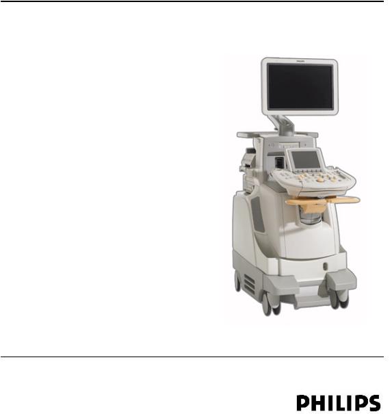
iU22 U l t r a s o u n d S y s t e m
User Manual
4535 614 45861 Rev A
August 2010
© 2010 Koninklijke Philips Electronics N.V. All rights reserved. Published in USA.

Manufactured by Philips Ultrasound
22100 Bothell-Everett Highway Bothell, WA 98021-8431 USA
Telephone: +1 425-487-7000 or 800-426-2670 Fax: +1 425-485-6080 www.philips.com/ultrasound
This Medical Device meets the provisions of the transposition of the Medical Device Directive 2007/47/EC within the country of origin of the Notified Body concerned with the device.
European Union Representative
Philips Medical Systems Nederland B.V.
Quality & Regulatory Affairs
Veenpluis 4-6
5684PC Best
The Netherlands
CAUTION
United States federal law restricts this device to sale by or on the order of a physician.
This document and the information contained in it is proprietary and confidential information of Philips Medical Systems («Philips») and may not be reproduced, copied in whole or in part, adapted, modified, disclosed to others, or disseminated without the prior written permission of the Philips Legal Department. This document is intended to be used by customers and is licensed to them as part of their Philips equipment purchase. Use of this document by unauthorized persons is strictly prohibited.
Philips provides this document without warranty of any kind, implied or expressed, including, but not limited to, the implied warranties of merchantability and fitness for a particular purpose.
Philips has taken care to ensure the accuracy of this document. However, Philips assumes no liability for errors or omissions and reserves the right to make changes without further notice to any products herein to improve reliability, function, or design. Philips may make improvements or changes in the products or programs described in this document at any time.
This product may contain remanufactured parts equivalent to new in performance, or parts that have had incidental use.
Philips Ultrasound products may be manufactured under or operate in accordance with one or more of the following United States patents and corresponding patents in other countries: U.S. Patent Numbers 5,315,999; 5,381,795; 5,402,793; 5,479,930; 5,482,045; 5,482,047; 5,555,887; 5,603,323; 5,634,465; 5,706,819; 5,715,823; 5,718,229; 5,720,291; 5,735,281; 5,833,613; 5,851,186; 5,879,303; 5,908,389; 5,951,478; 5,961,462; 6,043,590; 6,050,942; 6,126,599; 6,210,328; 6,224,552; 6,231,510; 6,251,074; 6,283,919; 6,299,579; 6,306,089; 6,390,981; 6,416,477; 6,516,215; 6,544,177; 6,629,927; 6,648,825; 6,663,569; 6,676,606; D369,307; Re36,564. Other patent applications are pending in various countries.
2iU22 User Manual 4535 614 45861
«Color Power Angio,» «HDI,» «QLAB,» «SonoCT,» «SONOS,» «xMATRIX,» and «XRES» are trademarks of Koninklijke Philips Electronics N.V.
Non-Philips product names may be trademarks of their respective owners.
|
iU22 User Manual |
3 |
|
|
4535 614 45861 |
||
4iU22 User Manual 4535 614 45861
Contents |
||
|
1 |
Read This First……………………………………………………………………………… |
17 |
|
Intended Audience……………………………………………………………………………………………… |
17 |
|
|
Warnings……………………………………………………………………………………………………………… |
17 |
|
|
Warning Symbols………………………………………………………………………………………………… |
18 |
|
|
User Information Components………………………………………………………………………….. |
19 |
|
|
Product Conventions………………………………………………………………………………………….. |
20 |
|
|
User Information Conventions…………………………………………………………………………… |
21 |
|
|
Upgrades and Updates……………………………………………………………………………………….. |
23 |
|
|
Customer Comments…………………………………………………………………………………………. |
23 |
|
|
Supplies and Accessories……………………………………………………………………………………. |
23 |
|
|
Customer Service……………………………………………………………………………………………….. |
26 |
|
|
WEEE Recycling Information……………………………………………………………………………… |
27 |
|
|
2 |
Safety…………………………………………………………………………………………… |
29 |
|
Electrical Safety…………………………………………………………………………………………………… |
29 |
|
|
Defibrillators………………………………………………………………………………………………….. |
32 |
|
|
Mechanical Safety………………………………………………………………………………………………… |
33 |
|
|
Equipment Protection…………………………………………………………………………………………. |
34 |
|
|
Symbols……………………………………………………………………………………………………………….. |
35 |
|
|
Biological Safety…………………………………………………………………………………………………… |
44 |
|
|
FDA Medical Alert on Latex………………………………………………………………………….. |
45 |
|
|
ALARA Education Program…………………………………………………………………………… |
47 |
|
|
Output Display………………………………………………………………………………………………. |
52 |
|
|
Control Effects……………………………………………………………………………………………….. |
56 |
|
|
Related Guidance Documents………………………………………………………………………. |
59 |
|
|
Acoustic Output and Measurement……………………………………………………………… |
59 |
|
|
Acoustic Output Tables…………………………………………………………………………………. |
63 |
|
|
Acoustic Measurement Precision and Uncertainty………………………………………. |
63 |
|
iU22 User Manual |
5 |
|
|
4535 614 45861 |
||

Contents
|
Operator Safety……………………………………………………………………………………………………… |
64 |
|
Repetitive Strain Injury ……………………………………………………………………………………. |
64 |
|
Foot Switch Warning………………………………………………………………………………………… |
65 |
|
Philips Transducers……………………………………………………………………………………………. |
65 |
|
Glutaraldehyde Exposure………………………………………………………………………………….. |
65 |
|
Infection Control………………………………………………………………………………………………. |
66 |
|
Electromagnetic Compatibility ……………………………………………………………………………… |
67 |
|
ECG Signal…………………………………………………………………………………………………………. |
69 |
|
Electrostatic Discharge Precautions…………………………………………………………………. |
69 |
|
Electromagnetic Emissions……………………………………………………………………………….. |
70 |
|
Approved Cables for Electromagnetic Compliance…………………………………………. |
71 |
|
Approved Transducers for Electromagnetic Compliance………………………………… |
73 |
|
Approved Accessories for Electromagnetic Compliance………………………………… |
73 |
|
Electromagnetic Immunity………………………………………………………………………………… |
75 |
|
Electromagnetic Interference……………………………………………………………………………. |
78 |
|
Recommended Separation Distance………………………………………………………………… |
80 |
|
Avoiding Electromagnetic Interference…………………………………………………………….. |
82 |
|
Use Restrictions Due to Interference……………………………………………………………… |
83 |
|
3 System Overview……………………………………………………………………………. |
85 |
|
System Capabilities………………………………………………………………………………………………… |
85 |
|
Measurements…………………………………………………………………………………………………… |
85 |
|
Transducer Types………………………………………………………………………………………………. |
86 |
|
Image Capture and Review……………………………………………………………………………….. |
86 |
|
Patient Data Protection……………………………………………………………………………………. |
86 |
|
System Options……………………………………………………………………………………………………… |
87 |
|
Imaging Options………………………………………………………………………………………………… |
87 |
|
Voice Control Option………………………………………………………………………………………. |
88 |
|
Connectivity Options……………………………………………………………………………………….. |
88 |
|
Clinical/Analysis Options………………………………………………………………………………….. |
89 |
|
Calculations Package Options………………………………………………………………………….. |
89 |
6iU22 User Manual 4535 614 45861

Contents
|
QLAB Advanced Quantification Software Options |
………………………………………….90 |
|
Stress Echocardiography…………………………………………………………………………………… |
90 |
|
Data Security…………………………………………………………………………………………………….. |
91 |
|
Technical Administration Option……………………………………………………………………… |
91 |
|
PercuNav Image Fusion and Navigation Device ……………………………………………… |
91 |
|
System Components……………………………………………………………………………………………… |
92 |
|
Video Monitor…………………………………………………………………………………………………… |
94 |
|
Control Module………………………………………………………………………………………………… |
94 |
|
Voice Control Headset……………………………………………………………………………………… |
96 |
|
Voice Annotation Microphone…………………………………………………………………………. |
96 |
|
On/Off (Power) Control…………………………………………………………………………………… |
96 |
|
Data Storage …………………………………………………………………………………………………….. |
97 |
|
Peripherals…………………………………………………………………………………………………………. |
99 |
|
Transducer Receptacles and Cable Management…………………………………………… |
101 |
|
Physio (ECG) Receptacles………………………………………………………………………………. |
103 |
|
Rear Panel and Power Switch…………………………………………………………………………. |
104 |
|
Wheel Brakes and Steering Locks………………………………………………………………….. |
105 |
|
4 Preparing the System……………………………………………………………………. |
107 |
|
Connecting Devices……………………………………………………………………………………………… |
107 |
|
External Printers……………………………………………………………………………………………… |
108 |
|
Connecting an External Printer……………………………………………………………………… |
109 |
|
Connecting the Foot Switch…………………………………………………………………………… |
112 |
|
External VCRs…………………………………………………………………………………………………. |
112 |
|
Connecting an External VCR………………………………………………………………………….. |
113 |
|
Configuring Print Functions……………………………………………………………………………. |
113 |
|
Connecting an External Color Monitor…………………………………………………………. |
114 |
|
Connecting the System to a Network…………………………………………………………… |
115 |
|
Moving the System……………………………………………………………………………………………….. |
116 |
|
Preparing and Moving……………………………………………………………………………………… |
117 |
|
Positioning in Confined Spaces……………………………………………………………………….. |
119 |
|
iU22 User Manual |
7 |
|
|
4535 614 45861 |
||

Contents
|
Setting Up After Moving…………………………………………………………………………………. |
120 |
|
Transporting the System………………………………………………………………………………………. |
122 |
|
5 Using the System………………………………………………………………………….. |
125 |
|
Turning the System On and Off…………………………………………………………………………… |
125 |
|
Setting the System Time and Date………………………………………………………………………. |
127 |
|
Using the Brakes and Steering Locks………………………………………………………………….. |
128 |
|
Monitor Adjustments…………………………………………………………………………………………… |
130 |
|
Positioning the Monitor………………………………………………………………………………….. |
130 |
|
Changing the Monitor Tint…………………………………………………………………………….. |
131 |
|
Changing the Default Monitor Brightness……………………………………………………… |
131 |
|
Adjusting for Ambient Light……………………………………………………………………………. |
132 |
|
Automatic Display Dimming…………………………………………………………………………… |
132 |
|
System Controls…………………………………………………………………………………………………… |
132 |
|
Control Panel………………………………………………………………………………………………….. |
133 |
|
Positioning the Control Module…………………………………………………………………….. |
134 |
|
Using the Retractable Keyboard…………………………………………………………………….. |
134 |
|
Touch Screen Brightness Controls…………………………………………………………………. |
134 |
|
Touch Screen Controls…………………………………………………………………………………… |
135 |
|
Touch Screen Knob Displays………………………………………………………………………….. |
137 |
|
Status Icons……………………………………………………………………………………………………… |
139 |
|
Voice Control……………………………………………………………………………………………………….. |
141 |
|
Voice Control Icons………………………………………………………………………………………… |
143 |
|
Turning Headsets On and Off………………………………………………………………………… |
144 |
|
Pairing Headsets……………………………………………………………………………………………… |
144 |
|
Configuring Headsets……………………………………………………………………………………… |
146 |
|
Muting the Headset………………………………………………………………………………………… |
147 |
|
Enabling Voice Control……………………………………………………………………………………. |
147 |
|
Voice Profiles…………………………………………………………………………………………………… |
147 |
|
Creating a Voice Profile………………………………………………………………………………….. |
148 |
|
Training Voice Profiles…………………………………………………………………………………….. |
149 |
8iU22 User Manual 4535 614 45861

Contents
|
Deleting Voice Profiles……………………………………………………………………………………. |
151 |
|
Background Noise…………………………………………………………………………………………… |
151 |
|
Communication Problems………………………………………………………………………………. |
151 |
|
Troubleshooting Voice Controls…………………………………………………………………….. |
152 |
|
Using Voice Commands………………………………………………………………………………….. |
152 |
|
Using the Keyword Feature……………………………………………………………………………. |
154 |
|
Specifying Keyword Default Settings………………………………………………………………. |
154 |
|
Voice Annotation Commands………………………………………………………………………… |
154 |
|
Using Voice Annotation………………………………………………………………………………….. |
155 |
|
System Security……………………………………………………………………………………………………. |
155 |
|
Logging On to the System………………………………………………………………………………. |
156 |
|
Logging Off of the System………………………………………………………………………………. |
156 |
|
Changing Your Password………………………………………………………………………………… |
156 |
|
Emergency Studies……………………………………………………………………………………………….. |
157 |
|
Temporary ID………………………………………………………………………………………………….. |
157 |
|
Starting Emergency Studies…………………………………………………………………………….. |
158 |
|
Imaging Display…………………………………………………………………………………………………….. |
159 |
|
Setting the Auto Freeze Function……………………………………………………………………….. |
162 |
|
Transducer Receptacles and Cable Management………………………………………………… |
162 |
|
Connecting Transducers…………………………………………………………………………………. |
164 |
|
Selecting a Transducer…………………………………………………………………………………….. |
165 |
|
ECG Feature………………………………………………………………………………………………………… |
166 |
|
DVD, CD, and USB Devices………………………………………………………………………………… |
166 |
|
Media Compatibility………………………………………………………………………………………… |
166 |
|
DVD Drive………………………………………………………………………………………………………. |
167 |
|
Loading and Ejecting a Disc…………………………………………………………………………….. |
168 |
|
Erasing a DVD…………………………………………………………………………………………………. |
168 |
|
USB Devices……………………………………………………………………………………………………. |
169 |
|
6 Customizing the System……………………………………………………………….. |
171 |
|
Presets………………………………………………………………………………………………………………….. |
171 |
|
iU22 User Manual |
9 |
|
|
4535 614 45861 |
||

Contents
|
Clinical Options and Tissue Specific Presets………………………………………………….. |
172 |
|
Quick Save Presets………………………………………………………………………………………….. |
172 |
|
Creating Quick Save Presets…………………………………………………………………………… |
172 |
|
Deleting Quick Save Presets…………………………………………………………………………… |
173 |
|
Copying Quick Save Presets to Removable Media………………………………………… |
174 |
|
Loading Quick Save Presets from Removable Media…………………………………….. |
175 |
|
System Setups………………………………………………………………………………………………………. |
175 |
|
Changing Setups………………………………………………………………………………………………. |
176 |
|
Hiding the Doppler Velocity Minus Sign………………………………………………………… |
176 |
|
Options………………………………………………………………………………………………………………… |
177 |
|
Installing Temporary Options…………………………………………………………………………. |
177 |
|
Purchasing Options…………………………………………………………………………………………. |
178 |
|
7 Performing an Exam……………………………………………………………………… |
179 |
|
New Patient Exams……………………………………………………………………………………………… |
179 |
|
Entering Patient Data……………………………………………………………………………………… |
180 |
|
Starting Emergency Studies…………………………………………………………………………….. |
180 |
|
Selecting in the Worklist………………………………………………………………………………… |
181 |
|
Searching in the Worklist……………………………………………………………………………….. |
182 |
|
Selecting a Transducer…………………………………………………………………………………………. |
182 |
|
Imaging Modes……………………………………………………………………………………………………… |
183 |
|
Using 2D Mode……………………………………………………………………………………………….. |
183 |
|
Annotation……………………………………………………………………………………………………………. |
184 |
|
Adding Labels Using Annotate ………………………………………………………………………. |
184 |
|
Adding Labels Using the Keyboard…………………………………………………………………. |
184 |
|
Adding an Image Title……………………………………………………………………………………… |
185 |
|
Displaying Body Markers………………………………………………………………………………… |
185 |
|
Recording……………………………………………………………………………………………………………… |
186 |
|
Using the VCR………………………………………………………………………………………………… |
186 |
|
Using the DVD Recorder……………………………………………………………………………….. |
187 |
|
Printing…………………………………………………………………………………………………………………. |
188 |
|
10 |
iU22 User Manual |
|
|
4535 614 45861 |
||

Contents
|
Printing Images………………………………………………………………………………………………… |
188 |
|
|
Review………………………………………………………………………………………………………………….. |
189 |
|
|
Starting Review……………………………………………………………………………………………….. |
189 |
|
|
Navigating Thumbnails and Images…………………………………………………………………. |
189 |
|
|
Capturing Images and Loops……………………………………………………………………………….. |
190 |
|
|
Measurement and Analysis…………………………………………………………………………………… |
191 |
|
|
Measuring 2D Distance…………………………………………………………………………………… |
192 |
|
|
Obtaining a Typical Labeled Measurement…………………………………………………….. |
193 |
|
|
Obtaining a Calculation Result……………………………………………………………………….. |
193 |
|
|
Ending an Exam…………………………………………………………………………………………………….. |
194 |
|
|
8 |
Transducers…………………………………………………………………………………… |
195 |
|
Selecting a Transducer…………………………………………………………………………………………. |
196 |
|
|
Clinical Options and Transducers……………………………………………………………………….. |
196 |
|
|
Indications for Use and Supporting Transducers………………………………………………… |
198 |
|
|
xMatrix Array Transducers………………………………………………………………………………….. |
200 |
|
|
X3-1 Description…………………………………………………………………………………………….. |
201 |
|
|
X6-1 Description…………………………………………………………………………………………….. |
202 |
|
|
X7-2 Description…………………………………………………………………………………………….. |
202 |
|
|
Transducer Maintenance………………………………………………………………………………………. |
202 |
|
|
Acoustic Artifacts………………………………………………………………………………………………… |
203 |
|
|
Acoustic Artifacts in 3D Imaging……………………………………………………………………. |
206 |
|
|
Transducer Covers………………………………………………………………………………………………. |
207 |
|
|
Transducer Storage………………………………………………………………………………………………. |
208 |
|
|
Storage for Transport ……………………………………………………………………………………. |
208 |
|
|
Daily and Long-Term Storage…………………………………………………………………………. |
209 |
|
|
9 |
Intraoperative Transducers……………………………………………………………. |
211 |
|
Operators of Intraoperative Transducers…………………………………………………………… |
211 |
|
|
Intended Uses for Intraoperative Transducers……………………………………………………. |
211 |
|
|
Patient Safety During Intraoperative Studies ……………………………………………………… |
212 |
|
|
Patient-Contact Parts……………………………………………………………………………………… |
213 |
|
iU22 User Manual |
11 |
|
|
4535 614 45861 |
||

Contents
|
Preventing Intraoperative Transducer Problems ……………………………………………….. |
213 |
|
Intraoperative Transducer Description……………………………………………………………….. |
214 |
|
Preparing Transducers for Intraoperative Use……………………………………………………. |
215 |
|
Disposable Drapes………………………………………………………………………………………….. |
216 |
|
Accessories for Intraoperative Transducers………………………………………………….. |
216 |
|
Electrical Safety and Intraoperative Transducers………………………………………………… |
216 |
|
Leakage Current Testing for Intraoperative Transducers…………………………………… |
217 |
|
Testing Intraoperative Transducer Leakage Current (Source)………………………. |
222 |
|
Testing Intraoperative Transducer Leakage Current (Sink)…………………………… |
222 |
|
10 Transesophageal Transducers………………………………………………………… |
225 |
|
Operators of TEE Transducers……………………………………………………………………………. |
225 |
|
Patient Safety During TEE Studies……………………………………………………………………….. |
225 |
|
Patient-Contact Parts……………………………………………………………………………………… |
230 |
|
Preventing TEE Transducer Problems…………………………………………………………………. |
231 |
|
Electrical Safety and TEE Transducers…………………………………………………………………. |
233 |
|
Leakage Current and TEE Transducers………………………………………………………….. |
233 |
|
Reducing Risks of Using TEE Transducers……………………………………………………… |
233 |
|
TEE Deflection Control Basics …………………………………………………………………………… |
234 |
|
Connecting an S7-2omni Transducer …………………………………………………………………. |
235 |
|
Connecting a T6H Transducer …………………………………………………………………………… |
236 |
|
S7-2omni TEE Transducer Description……………………………………………………………….. |
237 |
|
Using the S7-2omni Transducer…………………………………………………………………………… |
239 |
|
S7-2omni Deflection Controls ………………………………………………………………………. |
241 |
|
Manipulating the S7-2omni Tip……………………………………………………………………….. |
243 |
|
Rotating the S7-2omni Array………………………………………………………………………….. |
245 |
|
Calibrating the TEE Transducer……………………………………………………………………… |
246 |
|
Checking the TEE Transducer……………………………………………………………………………… |
247 |
|
TEE Transducer Inspection…………………………………………………………………………….. |
247 |
|
TEE Transducer Controls Inspection……………………………………………………………… |
247 |
|
Special Considerations for TEE Studies………………………………………………………………. |
248 |
|
12 |
iU22 User Manual |
|
|
4535 614 45861 |
||

Contents
|
Patient Selection for TEE Transducer Use |
……………………………………………………..249 |
|
Preparing Patients for TEE Studies…………………………………………………………………. |
249 |
|
TEE Study Guidelines……………………………………………………………………………………… |
250 |
|
Tip Fold-Over………………………………………………………………………………………………………. |
251 |
|
Recognizing Tip Fold-Over…………………………………………………………………………….. |
252 |
|
Correcting Tip Fold-Over………………………………………………………………………………. |
252 |
|
Preventing Tip Fold-Over ………………………………………………………………………………. |
252 |
|
TEE Temperature Sensing……………………………………………………………………………………. |
253 |
|
Ensuring Safe TEE Temperatures……………………………………………………………………. |
254 |
|
Manual Auto-Cool Feature…………………………………………………………………………….. |
254 |
|
Using the Temperature Display ……………………………………………………………………… |
255 |
|
Patient Temperature……………………………………………………………………………………….. |
255 |
|
Entering Patient Temperature…………………………………………………………………………. |
256 |
|
Resuming Imaging After Auto-Cool……………………………………………………………….. |
256 |
|
Patient Care After a TEE Study…………………………………………………………………………… |
257 |
|
TEE Accessories and Supplies……………………………………………………………………………… |
258 |
|
Bite Guards……………………………………………………………………………………………………… |
258 |
|
TEE Transducer Covers………………………………………………………………………………….. |
258 |
|
Tip Protectors…………………………………………………………………………………………………. |
259 |
|
Disposable Drapes………………………………………………………………………………………….. |
259 |
|
TEE Leakage Current Test…………………………………………………………………………………… |
259 |
|
TEE Test Background………………………………………………………………………………………. |
259 |
|
Testing TEE Transducer Leakage Current………………………………………………………. |
262 |
|
TEE Transducer References…………………………………………………………………………………. |
263 |
|
11 Endocavity Transducers………………………………………………………………… |
265 |
|
Operators of Endocavity Transducers………………………………………………………………… |
265 |
|
Patient Safety During Endocavity Studies……………………………………………………………. |
265 |
|
Preparing Transducers for Endocavity Use…………………………………………………………. |
266 |
|
C8-4v Description……………………………………………………………………………………………….. |
267 |
|
C9-5ec Description …………………………………………………………………………………………….. |
268 |
|
iU22 User Manual |
13 |
|
|
4535 614 45861 |
||

Contents
|
C10-3v Description……………………………………………………………………………………………… |
269 |
|
|
3D9-3v Description……………………………………………………………………………………………… |
271 |
|
|
Patient-Contact Parts…………………………………………………………………………………………… |
272 |
|
|
Biopsy with Endocavity Transducers……………………………………………………………………. |
273 |
|
|
12 |
Biopsy Guides……………………………………………………………………………….. |
275 |
|
Attaching and Removing a Biopsy Guide……………………………………………………………. |
275 |
|
|
Biopsy Guideline Display……………………………………………………………………………………… |
276 |
|
|
Displaying the Biopsy Guideline……………………………………………………………………… |
277 |
|
|
Moving the Biopsy Depth Cursor………………………………………………………………….. |
278 |
|
|
Biopsy Guide Alignment………………………………………………………………………………………. |
279 |
|
|
Preparation for Alignment Verification…………………………………………………………… |
280 |
|
|
Verifying the Biopsy Guide Alignment……………………………………………………………. |
280 |
|
|
Performing a Biopsy Procedure…………………………………………………………………………… |
282 |
|
|
Biopsy Guide Maintenance…………………………………………………………………………………… |
284 |
|
|
13 |
Transducer Care…………………………………………………………………………… |
285 |
|
Disinfectants and Gels Safety………………………………………………………………………………. |
285 |
|
|
Latex Product Alert………………………………………………………………………………………… |
286 |
|
|
Transmissible Spongiform Encephalopathy…………………………………………………….. |
286 |
|
|
Acoustic Coupling Medium…………………………………………………………………………………. |
287 |
|
|
Choosing a Disinfectant……………………………………………………………………………………….. |
287 |
|
|
General Cleaning for All Transducers…………………………………………………………………. |
287 |
|
|
Cleaning a Transducer…………………………………………………………………………………….. |
288 |
|
|
Disinfecting Transducers using a Wipe or Spray Method ………………………………….. |
289 |
|
|
Cleaning and Disinfecting Cables and Connectors…………………………………………….. |
291 |
|
|
Disinfection of Transducers by Immersion (High-Level Disinfection)……………….. |
293 |
|
|
Disinfecting Transducers by Immersion…………………………………………………………. |
294 |
|
|
Disinfecting TEE Transducers by Immersion………………………………………………………. |
295 |
|
|
Disinfecting TEE Transducers in an Automated Disinfector………………………………. |
298 |
|
|
Sterilizing Transducers…………………………………………………………………………………………. |
299 |
|
|
Disinfectants Compatibility………………………………………………………………………………….. |
302 |
|
14 |
iU22 User Manual |
|
|
4535 614 45861 |
||

Contents
|
Disinfectant Types…………………………………………………………………………………………… |
303 |
|
|
Factors Affecting Disinfectant Efficiency………………………………………………………… |
303 |
|
|
Disinfectants Compatibility Table ………………………………………………………………….. |
304 |
|
|
Gels Compatibility……………………………………………………………………………………………….. |
310 |
|
|
14 |
System Maintenance…………………………………………………………………….. |
311 |
|
Cleaning and Maintaining the System………………………………………………………………….. |
311 |
|
|
Cleaning the System and ECG Equipment…………………………………………………….. |
311 |
|
|
Disinfectants for System Surfaces…………………………………………………………………… |
313 |
|
|
Disinfecting System Surfaces…………………………………………………………………………… |
314 |
|
|
System Control Panel Maintenance……………………………………………………………….. |
315 |
|
|
Cleaning the Trackball…………………………………………………………………………………….. |
315 |
|
|
Air Filter Cleaning…………………………………………………………………………………………… |
316 |
|
|
Cleaning System Air Filters…………………………………………………………………………….. |
316 |
|
|
Specifying and Resetting the Air Filter Maintenance Status…………………………… |
319 |
|
|
Transducer Maintenance………………………………………………………………………………………. |
320 |
|
|
Printer Maintenance…………………………………………………………………………………………….. |
320 |
|
|
VCR and DVD Recorder Maintenance……………………………………………………………….. |
321 |
|
|
Troubleshooting……………………………………………………………………………………………………. |
322 |
|
|
Error Messages…………………………………………………………………………………………………….. |
323 |
|
|
Test Patterns………………………………………………………………………………………………………… |
324 |
|
|
Transferring the Test Patterns………………………………………………………………………… |
324 |
|
|
Using the Test Patterns…………………………………………………………………………………… |
324 |
|
|
Testing the System……………………………………………………………………………………………….. |
325 |
|
|
For Assistance………………………………………………………………………………………………………. |
326 |
|
|
15 |
Specifications………………………………………………………………………………… |
327 |
|
Safety Requirements……………………………………………………………………………………………. |
330 |
|
|
Index…………………………………………………………………………………………….. |
331 |
|
iU22 User Manual |
15 |
|
|
4535 614 45861 |
||

Contents
|
16 |
iU22 User Manual |
|
|
4535 614 45861 |
||

1 Read This First
This section contains important information about the user information for your product and about customer service.
Intended Audience
Before you use your user information, you need to be familiar with ultrasound techniques. Sonography training and clinical procedures are not included here.
This document is intended for sonographers, physicians, and biomedical engineers who operate and maintain your Philips product.
Warnings
Before using the system, read these warnings and the «Safety» section.
WARNINGS
•Do not remove system covers; hazardous voltages are present inside the system. To avoid electrical shock, use only supplied power cords and connect only to properly grounded wall (wall/mains) outlets.
•Do not operate the system in the presence of flammable anesthetics. Explosion can result.
•Medical equipment needs to be installed and put into service according to the special electromagnetic compatibility (EMC) guidelines provided in the «Safety» section.
•The use of portable and mobile radio-frequency (RF) communications equipment can affect the operation of medical equipment.
|
iU22 User Manual |
17 |
|
|
4535 614 45861 |
||
1 Read This First
Warning Symbols
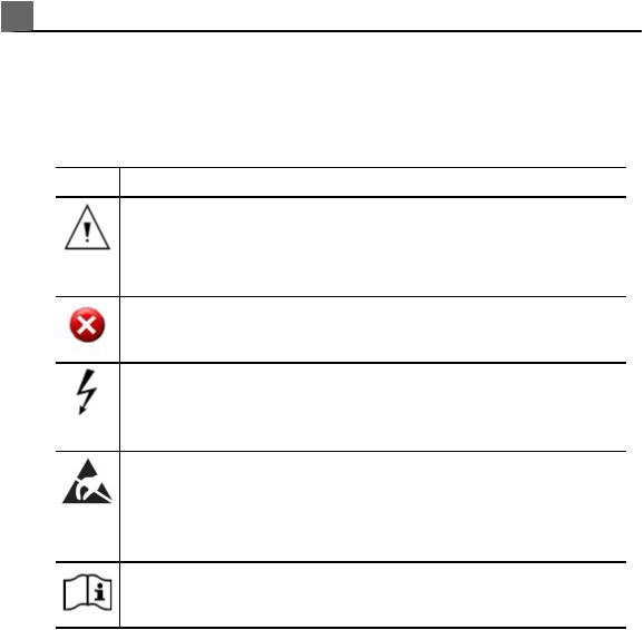
The system may use the following warning symbols. For additional symbols used on the system, see the «Safety» section.
|
Symbol |
Description |
|
Identifies a safety note. |
May also indicate that there is an impending loss of data that must be acknowledged.
Warning: Indicates that there is a possibility of a system malfunction that might prevent the use of the ultrasound system.
Dangerous voltages: Appears adjacent to high-voltage terminals, indicating the presence of voltages greater than 1,000 Vac (600 Vac in the United States).
Identifies ESD (electrostatic-discharge) sensitivity of a connector that is not tested as specified in IEC 60601-1-2. Do not touch exposed connector pins. Touching exposed pins can cause electrostatic discharge, which can damage the product.
Indicates that the user should see the instructions for use for safety information.
|
18 |
iU22 User Manual |
|
|
4535 614 45861 |
||

User Information Components
The user information provided with your product includes the following components:
•Compact Disc (CD): Includes all of the user information, except the Operating Notes. The instructions for using the CD are included with the CD.
•Operating Notes: Contains information that clarifies certain product responses that might be misunderstood or cause user difficulty.
•User Manual: Provided with the product and included on the CD. The User Manual introduces you to features and concepts, helps you set up your system, and includes important safety information. This manual also includes procedures for basic operation. For detailed operating instructions, see the Help.
•PercuNav User Manual : Introduces you to PercuNav features and concepts, helps you set up your system, includes important safety information, and provides instructions for use specific to the PercuNav system when integrated with the ultrasound system. For information about using the ultrasound system, see the user information for your ultrasound system.
•Help: Available on the system in some languages and included on the CD, the Help contains comprehensive instructions for using the system. The Help also provides reference information and descriptions of all controls and display elements. To display the Help, press Help on the system keyboard.
•Voice Control Quick Guide: Provided with the system and included on the CD, the Voice Control Quick Guide contains procedures for using the voice control option and lists all commands used for voice control and voice annotation.
|
iU22 User Manual |
19 |
|
|
4535 614 45861 |
||

1Read This First
•PercuNav Quick Reference Guide: Provides the most basic, procedural steps required to operate the PercuNav system.
•Acoustic Output Tables: Included on the CD, it contains information about acoustic output and patient-applied part temperatures.
•Medical Ultrasound Safety: Included on the CD, it contains information on bioeffects and biophysics, prudent use, and implementing ALARA (as low as reasonably achievable).
•Shared Roles for System and Data Security: Included on the CD, it contains guidelines to help you understand how the security of your Philips product could be compromised and information on Philips efforts to help you prevent security breaches.
•Media Compatibility: Included on the CD, it contains current information on media that are compatible with your system.
Product Conventions
Your Philips product uses certain conventions throughout the interface to make it easy for you to learn and use:
•Two unlabeled buttons, referred to as «Select controls,» are used with the trackball. Those controls, located on either side of the trackball, operate somewhat similarly to PC mouse buttons. Both Select controls function identically.
•Tabs along the top of the monitor display let you choose additional sets of setup options. Tabs along the top of the touch screen let you choose additional pages of controls.
•To type text into a text field, click in the field and use the keyboard.
•
To display a list, click the down arrow . To scroll through a list, click the arrows at either end of the scroll bar or drag the scroll box up or down.
•Controls on the control panel include buttons, knobs, slide controls, and a trackball. Press a button to activate or deactivate its function. Turn a knob to change the selected setting. Press a knob-button to activate its function, or turn it to change the selected setting. Move a slide control to change its setting. Roll the trackball in the direction that you want to move an object.
|
20 |
iU22 User Manual |
|
|
4535 614 45861 |
||

The current trackball function is displayed in the trackball select menu at the bottom of the display.
•Controls on the touch screen include buttons and knobs. To use a touch screen button, simply touch it. To use a touch screen knob, adjust the corresponding knob below the knob display (located in the bottom row of the touch screen).
•Many tabs on the touch screen contain two pages of controls. Touch Next and Previous to display these pages.
•Controls on the touch screen use several methods to indicate their status. Buttons that are either on or off have an indicator in the upper corner that lights when it is on. Buttons that select a setting generally display the active setting either within the button or on the monitor display. An arrow in the lower right corner of a button indicates that the button displays or hides a group of related buttons. Where only one button in a group can be selected at a time, the selected button is indicated by a gold outline or background. For more information, see «Touch Screen Controls» on page 135.
User Information Conventions
The user information for your product uses the following typographical conventions to assist you in finding and understanding information:
•All procedures are numbered, and all subprocedures are lettered. You must complete steps in the sequence they are presented to ensure success.
•Bulleted lists indicate general information about a particular function or procedure. They do not imply a sequential procedure.
•Control names and menu items or titles are spelled as they are on the system, and they appear in bold text. The only exceptions are the trackball and the buttons adjacent to it, which are unlabeled.
•Symbols appear as they appear on the system.
•The pointer is the cursor used to select elements on the display. Use the Pointer control to display the pointer.
•Point means to position the tip of the pointer or cursor on an item on the display.
|
iU22 User Manual |
21 |
|
|
4535 614 45861 |
||

1Read This First
•Click or select means to move the pointer or cursor to an object and press one of the unlabeled Select buttons located on either side of the trackball.
•Double-click means to quickly click twice to select an object or text.
•Drag means to place the pointer over an object and then press and hold one of the Select buttons while moving the trackball. Use this method to move an object on the display.
•Touch means to press a button on the touch screen, located above the control panel.
•Selecting means to specify an image or thumbnail to be exported or deleted. To select an image, either click on the thumbnail or the thumbnail number.
•Highlighting means to mark an image you want to reject during a protocol exam or an image you want to post-process. To highlight an image, click inside the image (but not on the number).
•The left side of the system is to your left as you stand in front of the system, facing the system. The front of the system is nearest to you as you operate it.
•Transducers and pencil probes both are referred to as transducers, unless the distinction is important to the meaning of the text.
Information that is essential for the safe and effective use of your product appears throughout your user information as follows:
WARNING
Warnings highlight information vital to the safety of you, the operator, and the patient.
CAUTION
Cautions highlight ways that you could damage the product and consequently void your warranty or service contract or ways that you could lose patient or system data.
NOTE
Notes bring your attention to important information that will help you operate the product more effectively.
|
22 |
iU22 User Manual |
|
|
4535 614 45861 |
||

Upgrades and Updates
Philips is committed to innovation and continued improvement. Upgrades may be announced that consist of hardware or software improvements. Updated user information will accompany those upgrades.
Customer Comments
If you have questions about the user information, or you discover an error in the user information, in the USA, please call Philips Ultrasound Customer Service at 800-722-9377; outside the USA, please call your local customer service representative.
Supplies and Accessories
To order ECG trunk cables, lead sets, and electrodes; transducer covers; biopsy guides; and other supplies and accessories, contact CIVCO Medical Solutions:
CIVCO Medical Solutions
102 First Street South, Kalona, IA 52247-9589
Telephone: 800-445-6741 (USA and Canada), +1 319-656-4447 (International)
Fax: 877-329-2482 (USA and Canada), +1 319-656-4451 (International)
E-mail: info@civco.com
Internet: www.civco.com
NOTE
Model or part numbers in the following tables are subject to change.
|
iU22 User Manual |
23 |
|
|
4535 614 45861 |
||

1 Read This First
|
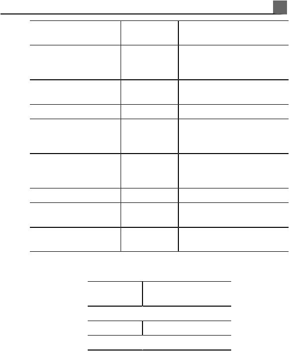
System Accessories |
||
|
Model/Part |
||
|
Accessory |
Number |
Description |
|
ECG cables and lead sets |
– |
See «Approved Cables for |
|
Electromagnetic Compliance» on |
||
|
page 71 |
||
|
ECG electrode |
40420A |
Pre-gelled snap electrode |
|
Tip guards |
610-748 |
Transducer tip protector for |
|
most TEE transducers |
||
|
610-945 |
Transducer tip protector for T6H |
|
|
and S7-2omni |
||
|
Bite guard |
M2203A |
Bite guard for TEE transducers |
|
Bite blocks |
610-979 |
Pediatric bite block |
|
610-160 |
Bite block without strap |
|
|
610-749 |
Bite block with strap |
|
|
Transducer covers |
610-840 |
Protective sheath for TEE |
|
610-860 |
transducers |
|
|
610-933 |
||
|
610-836 |
Protective sheath for endocavity |
|
|
610-843 |
transducers |
|
|
610-010 |
||
|
610-214 |
||
|
610-797 |
Intraoperative protective sheath |
|
|
for L15-7io transducers |
||
|
610-833 |
Covers for noninvasive or |
|
|
noncavity transducers |
|
24 |
iU22 User Manual |
|
|
4535 614 45861 |
||
|
Read This First 1 |
|||
|
Model/Part |
|||
|
Accessory |
Number |
Description |
|
|
Cables |
– |
See «Approved Cables for |
|
|
Electromagnetic Compliance» on |
|||
|
page 71 |
|||
|
Printers |
– |
See «External Printers» on page |
|
|
108 |
|||
|
Foot switch |
989605344671 |
Optional foot switch |
|
|
VCRs |
– |
See «Approved Accessories for |
|
|
Electromagnetic Compliance» on |
|||
|
page 73 |
|||
|
DVD recorders |
– |
See «Approved Accessories for |
|
|
Electromagnetic Compliance» on |
|||
|
page 73 |
|||
|
Biopsy guides |
– |
See the following table |
|
|
Transducers |
– |
See «Clinical Options and |
|
|
Transducers» on page 196 |
|||
|
Removable media |
– |
See «Media Compatibility» on page |
|
|
166 |
|||
|
Biopsy Guides |
|||
|
Transducer |
Compatible Biopsy |
||
|
Guide Model |
3D9-3v  989605351091
C5-1 989605369041
C5-2  989605341511
|
iU22 User Manual |
25 |
|
|
4535 614 45861 |
||

1 Read This First
|
Transducer |
Compatible Biopsy |
|
Guide Model |
|
|
C8-4v |
8500-8180-02 |
|
C8-5 |
989605341521 |
|
C9-4 |
8500-1290-01 |
|
C9-5ec |
8500-1704-01 |
|
C10-3v |
8500-8180-02 |
|
L12-5 50 mm |
8500-9089-03 |
|
L17-5 |
989605341541 |
|
L9-3 |
989605352591 |
|
S4-1 |
989605341531 |
|
VL13-5 |
989605377711 |
|
X3-1 |
989605361851 |
|
X6-1 |
453561442341 |
Customer Service
Customer service representatives are available worldwide to answer questions and to provide maintenance and service. Please contact your local Philips Ultrasound representative for assistance. You can also contact one of the following offices for referral to a customer service representative, or visit the Philips Ultrasound Web site:
www.philips.com/ultrasound
Corporate and North American Headquarters
22100 Bothell-Everett Highway, Bothell, WA 98021-8431, USA
800-722-9377
|
26 |
iU22 User Manual |
|
|
4535 614 45861 |
||

Asia Pacific Headquarters
Level 9, Three Pacific Place, 1 Queen’s Road East, Wanchai, Hong Kong
+852 2821 5888
European Headquarters (also serves Africa and the Middle East)
Philips Medizin Systeme Böblingen GmbH
Hewlett-Packard-Str. 2, 71034 Böblingen, Germany
+49 40 5078 4532
Latin American Headquarters
1550 Sawgrass Corporate Parkway, Suite 300, Sunrise, FL 33323, USA
+1 954-628-1000
WEEE Recycling Information
The European Union Directive on Waste Electrical and Electronic Equipment (WEEE) requires producers of electrical and electronic equipment to provide reuse and treatment information for each product. This information is provided in a Philips Healthcare Recycling Passport. Such «recycling passports» for Philips Ultrasound systems are available on this Web site:
www.healthcare.philips.com/main/about/sustainability/recycling/ultrasound.wpd
|
iU22 User Manual |
27 |
|
|
4535 614 45861 |
||

1 Read This First
|
28 |
iU22 User Manual |
|
|
4535 614 45861 |
||

2 Safety
Please read this information before using your ultrasound system. It applies to the ultrasound system, transducers, recording devices, and any optional equipment. This section covers general safety information only. Safety information that applies only to a specific task is included in the procedure for that task.
This device is intended for use by, or by the order of, and under the supervision of a licensed physician qualified to direct the use of the device.
A WARNING describes precautions necessary to prevent injury or loss of life.
A CAUTION describes precautions necessary to protect the equipment and patient or system data.
Electrical Safety
This equipment has been verified by a recognized third-party testing agency as a Class I device with Type BF and Type CF isolated patient-applied parts, and Type B non-isolated patient-applied parts. (The safety standards met by this system are included in the «Specifications» section.) For maximum safety observe these warnings and cautions:
WARNINGS
•Shock hazards may exist if this system, including all externally mounted recording and monitoring devices, is not properly grounded. Protection against electrical shock is provided by grounding the chassis with a
|
iU22 User Manual |
29 |
|
|
4535 614 45861 |
||

2 Safety
three-wire cable and plug. The system must be plugged into a grounded outlet. The grounding wire must not be removed or defeated.
•To avoid the risk of electrical shock, never connect the system power cord to a power strip or an extension cord. When using the power cord, always connect it directly to a grounded wall outlet.
•Because Type B and BF transducers are not isolated and have a higher inherent leakage current, those transducers are not intended for invasive use.
•Do not remove the protective covers on the system; hazardous voltages are present inside. Cabinet panels must be in place while the system is in use. All internal adjustments and replacements must be made by a qualified Philips Ultrasound field service engineer.
•Do not operate this system in the presence of flammable gases or anesthetics. Explosion can result. The system is not compliant in AP/APG environments as defined by IEC 60601-1.
•To avoid risk of electrical shock hazards, always inspect the transducer before use: Check the face, housing, and cable before use. Do not use if the face is cracked, chipped, or torn; the housing is damaged; or the cable is abraded.
•To avoid risk of electrical shock hazards, always turn off the system and disconnect it from the wall outlet before cleaning the system.
•All patient-contact devices, such as transducers, pencil probes, and ECG leads not specifically indicated as defibrillation-proof must be removed from patient contact before application of a high-voltage defibrillation pulse. See «Defibrillators» on page 32.
•During transesophageal echocardiographic (TEE) procedures, either remove the TEE transducer from the patient or disconnect the TEE transducer from the system immediately following image acquisition.
•Ultrasound equipment in normal operation, as with other medical electronic diagnostic equipment, uses high-frequency electrical signals that can interfere with pacemaker operation. Though the possibility of interference is slight, be alert to this potential hazard and stop system operation immediately if you note interference with a pacemaker.
•When using additional peripheral equipment powered from an electrical source other than the ultrasound system, the combination is considered
|
30 |
iU22 User Manual |
|
|
4535 614 45861 |
||

Safety 2
to be a medical system. It is your responsibility to comply with IEC 60601-1 and test the system to those requirements. If you have questions, contact your Philips representative.
•Do not use nonmedical peripherals, such as report printers, within 1.5 m (5 ft) of a patient, unless the nonmedical peripherals receive power from an isolated power outlet on the Philips ultrasound system, or from an isolation transformer that meets medical safety standards, as defined by standard IEC 60601-1.
•The system and patient-applied parts meet the standard IEC 60601-1. Applied voltages exceeding the standard, although unlikely, may result in electrical shock to the patient or operator.
•Connection of optional devices not supplied by Philips Ultrasound could result in electrical shock. When such optional devices are connected to your ultrasound system, ensure that the total system earth leakage current does not exceed 500 µA, or in the United States, 300 µA.
•To avoid risk of electrical shock, do not use any transducer that has been immersed beyond the specified cleaning or disinfection level. See the «Transducer Care» section.
•To avoid risks of electrical shock and fire hazards, inspect the system power cord and plug regularly. Ensure that they are not damaged in any way.
•Operating the system with physio input signals that are below the specified minimum levels may cause inaccurate results. See the «Specifications» section.
•Electrosurgical units (ESUs) and other devices intentionally introduce radio frequency electromagnetic fields or currents into patients. Because imaging ultrasound frequencies are coincidentally in the radio frequency range, ultrasound transducer circuits are susceptible to radio frequency interference. While an ESU is in use, severe noise interferes with the black-and-white image and completely obliterates the color image. Concurrent failures in an ESU or other device and in the outer layer of the TEE transducer shaft can cause electrosurgical currents to return along the transducer conductors. This could burn the patient, and the ultrasound system and the transducer could also be damaged. Be aware that a disposable transducer cover provides no protective electrical insulation at ESU frequencies.
|
iU22 User Manual |
31 |
|
|
4535 614 45861 |
||

2Safety
•To avoid risk of a burn hazard, do not use transducers with high-frequency surgical equipment. A burn hazard may result from a defect in the high-frequency surgical neutral electrode connection.
•Using cables, transducers, and accessories other than those specified for use with the system may result in increased emissions from, or decreased immunity of, the system.
CAUTIONS
•Although your system has been manufactured in compliance with existing EMI/EMC requirements, use of this system in the presence of an electromagnetic field can cause momentary degradation of the ultrasound image. When interference is present or intermittent, use caution when continuing to use the system. If interference occurs often, review the environment in which the system is being used, to identify possible sources of radiated emissions. These emissions could be from other electrical devices used within the same room or an adjacent room. Communication devices such as cellular phones and pagers can cause these emissions. The existence of radio, TV, or microwave transmission equipment located nearby can cause emissions. In cases where EMI is causing disturbances, it may be necessary to relocate your system.
•For information on electromagnetic emissions and immunity as it applies to the system, see «Electromagnetic Compatibility» on page 67. Ensure that the operating environment of your system meets the conditions specified in the referenced information. Operating the system in an environment that does not meet those conditions may degrade system performance.
Defibrillators
Observe the following warnings when using a transducer when a defibrillation is required.
|
32 |
iU22 User Manual |
|
|
4535 614 45861 |
||

Safety 2
WARNINGS
•Before defibrillation, always remove the transducer from the patient.
•Before defibrillation, always disconnect the transducer from the system.
•A disposable transducer cover provides no protective electrical insulation against defibrillation.
•A small hole in the outer layer of the transducer opens a conductive path to grounded metal parts of the transducer. The secondary arcing that could occur during defibrillation could cause patient burns. The risk of burns is reduced, but not eliminated, by using an ungrounded defibrillator.
Use defibrillators that do not have grounded patient circuits. To determine whether or not a defibrillator patient circuit is grounded, see the defibrillator service guide, or consult a biomedical engineer.
Mechanical Safety
A list of precautions related to mechanical safety follows; observe these precautions when using the system:
WARNINGS
•Be aware of the wheels on the system cart, especially when moving the system. The system could cause injury to you or others if it rolls over feet or into shins. Use caution when going up or down ramps.
•When attempting to overcome an obstacle, do not push the system from either side with excessive force, which could cause the system to tip over.
•Position external hardcopy devices away from the system. Ensure that they are secure. Do not stack them on the system.
•When positioning the monitor, move it carefully to avoid pinching hands or extremities against other objects, such as a bed rail.
•Never park the system on an incline.
•The brakes are intended as a convenience. To increase cart security, use wheel chocks when the system is parked.
•If system operation is abnormal after you move or transport the system, contact Philips Ultrasound Customer Service immediately. System
|
iU22 User Manual |
33 |
|
|
4535 614 45861 |
||

2 Safety
components are installed securely and can withstand considerable shock, but excessive shock can cause a system failure.
•Before moving the system, ensure that the keyboard is retracted, the control panel is centered, and the monitor is locked (see «Positioning the Control Module» on page 134 and «Preparing and Moving» on page 117). When extended, the keyboard might be damaged if it hits another object, and the video monitor could swing out during transport, causing injury or equipment damage.
CAUTIONS
•Before moving the system, ensure that the system is secured for transport. On some systems, that may include ensuring that the monitor is latched, to prevent monitor damage during transport.
•Ensure that the cables for all patient-applied parts are secure before moving the system. Use the cable management system to ensure that transducer cables are protected from damage.
•Do not roll the system over transducer cables or power cables.
Equipment Protection
Follow these precautions to protect your system:
CAUTIONS
•Excessive bending or twisting of cables on patient-applied parts may cause failure or intermittent operation of the system. Do not roll the system over cables, which may damage them.
•Improper cleaning or sterilization of a patient-applied part may cause permanent damage. For cleaning and disinfection instructions, see the «Transducer Care» section.
•Do not submerge the cables of patient-applied parts in solution. The cables are not liquid-tight beyond the applied part/cable or cable/connector interfaces.
|
34 |
iU22 User Manual |
|
|
4535 614 45861 |
||

Safety 2
•In general, only the area of the transducer acoustic window is liquid-tight. Except where specified in specific transducer-cleaning instructions, do not immerse the remainder of a transducer in any liquid.
•Do not use solvents, such as thinner or benzine, or abrasive cleaners on the system, transducers, or any hardcopy device.
•For optimal performance, connect your ultrasound system to a circuit dedicated solely for the system. Do not connect life-support devices to the same circuit as the ultrasound system.
•If systems, transducers, and peripherals have been in an environment below 10°C (50°F), allow them to reach room temperature before connecting or turning them on. Philips recommends allowing 24 hours for complete normalization. Otherwise, condensation inside the devices could cause damage. If the device was only briefly exposed to temperatures below 10°C (50°F), then the time required for the device to return to room temperature could be significantly less than 24 hours.
•To avoid damaging the flat-panel display in the monitor, do not store the system where the ambient temperature exceeds 65°C (149°F).
Symbols
The International Electrotechnical Commission (IEC) has established a set of symbols for medical electronic equipment that classify a connection or warn of potential hazards. Of those symbols, the following may be used on your Philips product and its accessories and packaging.
Isolated patient connection (Type BF applied part).
Defibrillation-proof patient connection (Type BF applied part).
|
iU22 User Manual |
35 |
|
|
4535 614 45861 |
||

2 Safety
Non-isolated patient connection (Type B applied part).
Isolated patient connection for applied part intended for intraoperative use, including direct cardiac application and contact with major vessels (Type CF applied part).
Defibrillation-proof patient connection (Type CF applied part).
Identifies ESD (electrostatic-discharge) sensitivity of a connector that is not tested as specified in
IEC 60601-1-2. Do not touch exposed connector pins. Touching exposed pins can cause electrostatic discharge, which can damage the product.
Identifies an On/Off control.
On a two-position power switch, represents On and Off.
Identifies a safety note.
Indicates that the user should see the instructions for use for safety information.
|
36 |
iU22 User Manual |
|
|
4535 614 45861 |
||
Safety 2
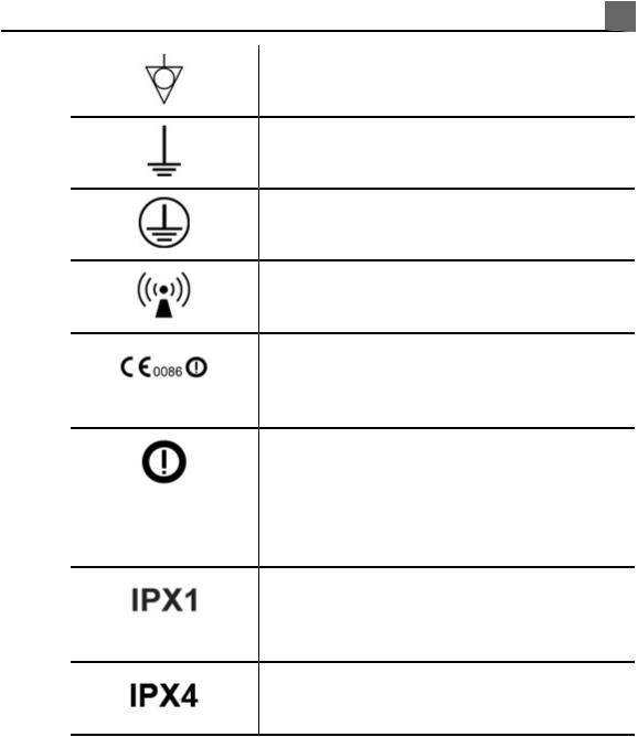
Identifies equipotential ground.
Identifies earth ground.
Identifies protective earth ground.
Nonionizing electromagnetic radiation. Indicates that interference may occur in the vicinity of equipment marked with this symbol.
The radio component contained in this device is compliant to Council Directive 1999/5/EC (Radio Equipment and Telecommunications Terminal Equipment Directive).
Class 2 radio equipment identifier per Directive 1999/5/EC. European Union member states may apply restrictions on putting this device into service or placing it on the market. This device is intended to be connected to the Publicly Available Interfaces for use throughout the European Economic Area.
Indicates that the device is protected against the effects of vertically falling water. This degree of protection can apply to transducers or foot-operated devices.
Indicates that the device is protected against the effects of splashing liquids. This degree of protection can apply to foot-operated devices.
|
iU22 User Manual |
37 |
|
|
4535 614 45861 |
||

2 Safety
Indicates that the device is protected against the effects of immersion. This degree of protection can apply to transducers and foot-operated devices.
Indicates that the device is protected against the effects of immersion for up to 60 minutes. This degree of protection can apply to foot-operated devices.
Indicates the need for separate collection for electrical and electronic equipment in compliance with the Waste Electrical and Electronic Equipment
(WEEE) Directive. When accompanied by  or
or  , components of the device may contain lead or mercury, respectively, which must be recycled or disposed of in accordance with local, state, or federal laws. The backlight lamps in an LCD system monitor contain mercury.
Do not throw away. Dispose of in accordance with local, state, or federal laws.
Do not reuse.
Use-by date.
|
38 |
iU22 User Manual |
|
|
4535 614 45861 |
||

Safety 2
Global Medical Device Nomenclature Code.
Indicates a possible crushing hazard to hands.
Warns that the system should not be used stacked with other equipment. If the system is used stacked with or adjacent to other equipment, verify normal operation before use.
Indicates the temperature range (noncondensing) for transport and storage. (Does not apply to media.)
Indicates the atmospheric pressure range for transport and storage.
Indicates the relative humidity range (noncondensing) for transport and storage.
Indicates that a connector receives alternating current.
Identifies fuse boxes or their locations. For continued protection from fire and shock, replace fuses only with fuses of the same type and rating.
|
iU22 User Manual |
39 |
|
|
4535 614 45861 |
||
2 Safety
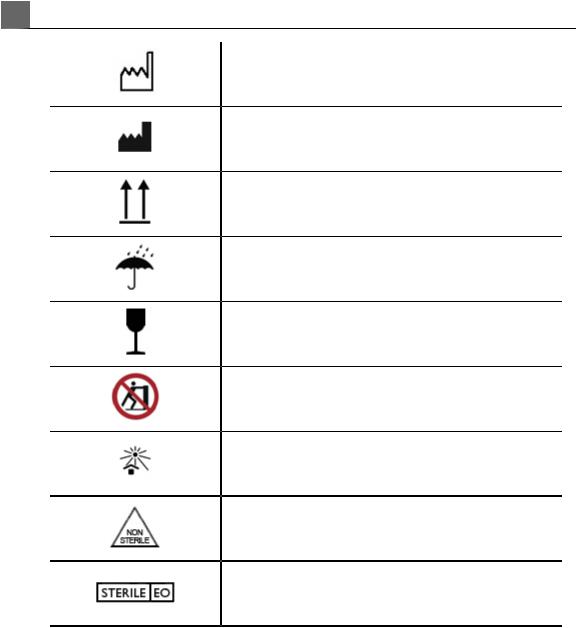
Identifies the date of manufacture.
Identifies the legal manufacturer.
This side up: Points toward the side of the shipping crate that should be kept facing up.
Indicates that the device should be kept dry.
Indicates that the device is fragile; handle with care.
Warns of system over-balance due to external force. (Do not push on the monitor to move the system.)
Keep away from sunlight.
Non-sterile.
Sterilized using ethylene oxide.
|
40 |
iU22 User Manual |
|
|
4535 614 45861 |
||
Safety 2
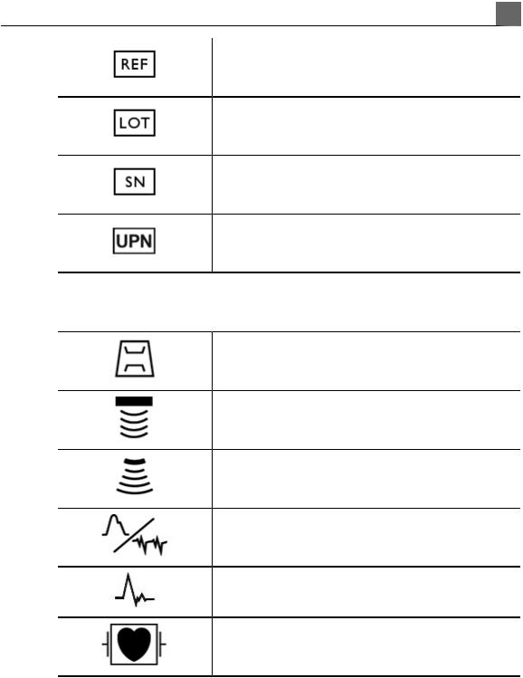
Catalog number.
Batch code.
Serial number.
Universal part number.
The following symbols may also be used on the system and its accessories and packaging:
Connection for a pencil probe
Connection for a pencil probe
Connection for a transducer
Connection for ECG leads
Connection for ECG leads
Connection for ECG leads
|
iU22 User Manual |
41 |
|
|
4535 614 45861 |
||
2 Safety
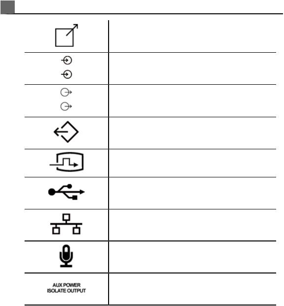
Print remote output
Input port for audio left/right, VHS/S-VHS, microphone, CD, or DVD
Output port for audio left/right, VHS/S-VHS, video patient monitor, black-and-white printer, or interlaced RGB output port
VGA or parallel output port
DVI video output receptacle
USB input/output port
Ethernet connection
System microphone
Isolated auxiliary power provided for connection of Philips-approved remote accessories
|
42 |
iU22 User Manual |
|
|
4535 614 45861 |
||

Safety 2
Foot switch
Indicates the atmospheric pressure range for transport and storage.
SVGA connection
Two video receptacles provide DVI-D digital video for flat-panel monitors.
S-Video connection
B/W Composite video output connection
Color composite video output connection
Video print trigger connection
Russian approval (GOST)
The following symbols may be used inside the system:
Dangerous voltages: Appears adjacent to high-voltage terminals, indicating the presence of voltages greater than 1,000 Vac (600 Vac in the United States).
Indicates equipotential ground.
|
iU22 User Manual |
43 |
|
|
4535 614 45861 |
||

2 Safety
Biological Safety
This section contains information about biological safety and a discussion of the prudent use of the system.
A list of precautions related to biological safety follows; observe these precautions when using the system. For more information refer to Medical Ultrasound Safety on your user information CD.
WARNINGS
•Do not use the system if an error message on the video display indicates that a hazardous condition exists. Note the error code, turn off power to the system, and call your customer service representative.
•Do not use a system that exhibits erratic or inconsistent image updating. Discontinuities in the scanning sequence indicate a hardware failure that must be corrected before use.
•Perform ultrasound procedures prudently. Use the ALARA (as low as reasonably achievable) principle.
•Use only acoustic standoffs that have been approved by Philips Ultrasound. For information on ordering approved accessories, see «Supplies and Accessories» on page 23.
•Verify the alignment of the biopsy guide before use. See the «Biopsy Guides» section.
•Verify the condition of the biopsy needle before use. Do not use a bent biopsy needle.
•Transducer covers may contain natural rubber latex. Those covers may cause allergic reactions in some individuals. See «FDA Medical Alert on Latex» on page 45.
•In contrast studies using a high-MI acoustic field, capillary rupture, due to microbubble expansion within a capillary in an acoustic field, can cause extravasation. References: (1) Skyba, D.M., Price, R.J., Linka, A.Z., Skalak, T.C., Kaul, S. «Direct in vivo visualization of intravascular destruction of microbubbles by ultrasound and its local effects on tissue.» Circulation, 1998; 98:290-293. (2) van Der Wouw, P.A., Brauns, A.C., Bailey, S.E., Powers, J.E.,
|
44 |
iU22 User Manual |
|
|
4535 614 45861 |
||

Safety 2
Wilde, A.A. «Premature ventricular contractions during triggered imaging with ultrasound contrast.» Journal of the American Society of Echocardiography, 2000;13(4):288-94.
•Preventricular contractions can be caused by the oscillations of microbubbles when a high-MI acoustic field is triggered in the heart at the end of systole. In a very sick patient with certain risk factors, theoretically, this could lead to ventricular fibrillation. Reference: van Der Wouw, P.A., Brauns, A.C., Bailey, S.E., Powers, J.E., Wilde, A.A. «Premature ventricular contractions during triggered imaging with ultrasound contrast.» Journal of the American Society of Echocardiography, 2000;13(4):288-94.
•If a sterile transducer cover becomes compromised during an intraoperative application involving a patient with transmissible spongiform encephalopathy, such as Creutzfeldt-Jakob disease, follow the guidelines of the U.S. Centers for Disease Control and this document from the World Health Organization: WHO/CDS/ APH/2000/3, WHO Infection Control Guidelines for Transmissible Spongiform Encephalopathies. The transducers for your system cannot be decontaminated using a heat process.
•If the system becomes contaminated internally with bodily fluids carrying pathogens, you must immediately notify your Philips service representative. Components inside the system cannot be disinfected. In that case, the system must be disposed of as biohazardous material in accordance with local or federal laws.
•The backlight lamps in the system displays contain mercury and must be recycled or disposed of according to local, state, or federal laws.
•Select the correct application when starting an exam, and remain in that application throughout the exam. Some applications are for parts of the body that require lower limits for acoustic output. One example is the ophthalmic application, which is activated by selecting a Tissue Specific preset such as Orbital TCD. When performing an ophthalmic exam, use only an ophthalmic preset.
FDA Medical Alert on Latex
March29,1991,AllergicReactionstoLatex-ContainingMedicalDevices
|
iU22 User Manual |
45 |
|
|
4535 614 45861 |
||

2 Safety
Because of reports of severe allergic reactions to medical devices containing latex (natural rubber), the FDA is advising health care professionals to identify their latex sensitive patients and be prepared to treat allergic reactions promptly. Patient reactions to latex have ranged from contact urticaria to systemic anaphylaxis. Latex is a component of many medical devices, including surgical and examination gloves, catheters, intubation tubes, anesthesia masks, and dental dams.
Reports to the FDA of allergic reactions to latex-containing medical devices have increased lately. One brand of latex cuffed enema tips was recently recalled after several patients died as a result of anaphylactoid reactions during barium enema procedures. More reports of latex sensitivity have also been found in the medical literature. Repeated exposure to latex both in medical devices and in other consumer products may be part of the reason that the prevalence of latex sensitivity appears to be increasing. For example, it has been reported that 6% to 7% of surgical personnel and 18% to 40% of spina bifida patients are latex sensitive.
Proteins in the latex itself appear to be the primary source of the allergic reactions. Although it is not now known how much protein is likely to cause severe reactions, the FDA is working with manufacturers of latex-containing medical devices to make protein levels in their products as low as possible.
FDA’s recommendations to health professionals in regard to this problem are as follows:
•When taking general histories of patients, include questions about latex sensitivity. For surgical and radiology patients, spina bifida patients and health care workers, this recommendation is especially important. Questions about itching, rash or wheezing after wearing latex gloves or inflating a toy balloon may be useful. Patients with positive histories should have their charts flagged.
•If latex sensitivity is suspected, consider using devices made with alternative materials, such as plastic. For example, a health professional could wear a non-latex glove over the latex glove if the patient is sensitive. If both the health professional and the patient are sensitive, a latex middle glove could
|
46 |
iU22 User Manual |
|
|
4535 614 45861 |
||

Safety 2
be used. (Latex gloves labeled “Hypoallergenic” may not always prevent adverse reactions.)
•Whenever latex-containing medical devices are used, especially when the latex comes in contact with mucous membranes, be alert to the possibility of an allergic reaction.
•If an allergic reaction does occur and latex is suspected, advise the patient of a possible latex sensitivity and consider an immunologic evaluation.
•Advise the patient to tell health professionals and emergency personnel about any known latex sensitivity before undergoing medical procedures. Consider advising patients with severe latex sensitivity to wear a medical identification bracelet.
The FDA is asking health professionals to report incidents of adverse reactions to latex or other materials used in medical devices. (See the October 1990 FDA Drug Bulletin.) To report an incident, call the FDA Problem Reporting Program, operated through the U.S. Pharmacopoeia toll-free number: 800-638-6725. (In Maryland, call collect 301-881-0256.)
For a single copy of a reference list on latex sensitivity, write to: LATEX, FDA, HFZ-220, Rockville, MD 20857.
NOTE
The ultrasound system and transducers described in this document do not contain natural rubber latex that contacts humans. Natural rubber latex is not used on any Philips ultrasound transducer. It also is not used on Philips ECG cables for the products described in this document.
ALARA Education Program
The guiding principle for the use of diagnostic ultrasound is defined by the «as low as reasonably achievable» (ALARA) principle. The decision as to what is reasonable has been left to the judgment and insight of qualified personnel. No set of rules can be formulated that would be sufficiently complete to dictate the correct response to every circumstance. By keeping ultrasound exposure as low as possible, while obtaining diagnostic images, users can minimize ultrasonic bioeffects.
|
iU22 User Manual |
47 |
|
|
4535 614 45861 |
||

2 Safety
Since the threshold for diagnostic ultrasound bioeffects is undetermined, it is the sonographer’s responsibility to control total energy transmitted into the patient. The sonographer must reconcile exposure time with diagnostic image quality. To ensure diagnostic image quality and limit exposure time, an ultrasound system provides controls that can be manipulated during the exam to optimize the results of the exam.
The ability of the user to abide by the ALARA principle is important. Advances in diagnostic ultrasound, not only in the technology but in the applications of that technology, have resulted in the need for more and better information to guide the user. The output display indices are designed to provide that important information.
There are a number of variables which affect the way in which the output display indices can be used to implement the ALARA principle. These variables include index values, body size, location of the bone relative to the focal point, attenuation in the body, and ultrasound exposure time. Exposure time is an especially useful variable, because it is controlled by the user. The ability to limit the index values over time supports the ALARA principle.
Applying ALARA
The system imaging mode used depends upon the information needed. 2D and M-mode imaging provide anatomical information, while Doppler, Color Power Angio (CPA), and Color imaging provide information about blood flow. A scanned mode, like 2D or Color, disperses or scatters the ultrasonic energy over an area, while an unscanned mode, like M-mode or Doppler, concentrates ultrasonic energy. Understanding the nature of the imaging mode being used allows the sonographer to apply the ALARA principle with informed judgment. Additionally, the transducer frequency, system setup values, scanning techniques, and operator experience allow the sonographer to meet the definition of the ALARA principle.
The decision as to the amount of acoustic output is, in the final analysis, up to the system operator. This decision must be based on the following factors: type of patient, type of exam, patient history, ease or difficulty of obtaining diagnostically useful information, and the potential localized heating of the patient due to transducer surface temperatures. Prudent use of the system occurs when
|
48 |
iU22 User Manual |
|
|
4535 614 45861 |
||

Safety 2
patient exposure is limited to the lowest index reading for the shortest amount of time necessary to achieve acceptable diagnostic results.
Although a high index reading does not mean that a bioeffect is actually occurring, a high index reading should be taken seriously. Every effort should be made to reduce the possible effects of a high index reading. Limiting exposure time is an effective way to accomplish this goal.
There are several system controls that the operator can use to adjust the image quality and limit the acoustic intensity. These controls are related to the techniques that an operator might use to implement ALARA. These controls can be divided into three categories: direct, indirect, and receiver controls.
Acoustic Output Limits
This ultrasound system maintains acoustic output below the appropriate limits for each application, as listed here. The significant difference in magnitude emphasizes the need to select the correct application and remain in that application, so the correct application limits are in use for the appropriate application.
Limits for Non-Ophthalmic Applications
•Ispta.3 ≤ 720 mW/cm2
•MI ≤ 1.9
•TI ≤ 6.0
Limits for Ophthalmic Applications
•Ispta.3 ≤ 50 mW/cm2
•MI ≤ 0.23
•TI ≤ 1.0
Direct Controls
Application selection and the output-power control directly affect acoustic intensity. There are different ranges of allowable intensity or output based on your selection. Selecting the correct range of acoustic intensity for the application is one of the first things that occurs in any exam. For example, peripheral vascular intensity levels are not recommended for fetal exams. Some systems automatically
|
iU22 User Manual |
49 |
|
|
4535 614 45861 |
||

2 Safety
select the proper range for a particular application, while others require manual selection. Ultimately, the user has the responsibility for proper clinical use. The ultrasound system provides both automatic (default) settings and manual (user-selectable) settings.
Output power has direct impact on acoustic intensity. Once the application has been established, the power control can be used to increase or decrease the intensity output. The power control allows you to select intensity levels less than the established maximum. Prudent use dictates that you select the lowest output intensity that is consistent with good image quality.
Indirect Controls
The indirect controls are those that have an indirect effect on acoustic intensity. These controls affect imaging mode, pulse repetition frequency, focus depth, pulse length, and transducer selection.
The choice of imaging mode determines the nature of the ultrasound beam. 2D is a scanning mode; Doppler is a stationary or unscanned mode. A stationary ultrasound beam concentrates energy in a single location. A moving or scanned ultrasound beam disperses the energy over an area and the beam is concentrated on the same area for a fraction of the time as that of an unscanned mode.
Pulse repetition frequency or rate refers to the number of ultrasound bursts of energy over a specific period of time. The higher the pulse repetition frequency, the more pulses of energy in a period of time. Several controls affect pulse repetition frequency: focal depth, display depth, sample volume depth, flow optimization, scale, number of focal zones, and sector-width controls.
Focus of the ultrasound beam affects the image resolution. To maintain or increase resolution at a different focus requires a variation in output over the focal zone. This variation of output is a function of system optimization. Different exams require different focal depths. Setting the focus at the proper depth improves the resolution of the structure of interest.
Pulse length is the time during which the ultrasonic burst is turned on. The longer the pulse, the greater the time-average intensity value. The greater the time-average intensity, the greater the likelihood of temperature increase and cavitation. Pulse length, burst length, or pulse duration is the output pulse
|
50 |
iU22 User Manual |
|
|
4535 614 45861 |
||
 Loading…
|
Detail Specifications: 841/841150-iu22.pdf file (24 Dec 2022) |
Accompanying Data:
Philips iU22 Medical Equipment PDF Training Manual (Updated: Saturday 24th of December 2022 11:50:44 PM)
Rating: 4.1 (rated by 67 users)
Compatible devices: BiPAP Pro Bi-Flex, HeartStart M3535A, HeartStart MRx, InCourage, MX400, Respironics Actiwatch Series, AVENT SCF153, BiPAP autoSV advanced system One.
Recommended Documentation:
Text Version of Training Manual
(Ocr-Read Summary of Contents, UPD: 24 December 2022)
-
121, Conquest Imaging Ultrasound Sales Service Repair Training 1815 Industrial Drive, Suite 100 Stockton, CA 95206 PH: 209-942-2654 FAX: 209-942-2572 Rev3 070208.dms — 122 — 5. Clean dust and debris from the trackball reservoir with a cotton swab moistened with alcohol. 6. Clean the shaft and rollers with a cotton swab moistened with alcohol. 7.…
-
60, Conquest Imaging Ultrasound Sales Service Repair Training 1815 Industrial Drive, Suite 100 Stockton, CA 95206 PH: 209-942-2654 FAX: 209-942-2572 Rev3 070208.dms — 61 — iU22/iE33™ Chapter 2 Operational Testing
… -
124, Conquest Imaging Ultrasound Sales Service Repair Training 1815 Industrial Drive, Suite 100 Stockton, CA 95206 PH: 209-942-2654 FAX: 209-942-2572 Rev3 070208.dms — 125 — Method 1 1. Power up the system. 2. Check with the customer and save selected exams to DVD. 3. Press Setup on the QWERTY top row. 4. Select Print/Network button on the left s…
-
56, Philips iU22 Conquest Imaging Ultrasound Sales Service Repair Training 1815 Industrial Drive, Suite 100 Stockton, CA 95206 PH: 209-942-2654 FAX: 209-942-2572 Rev3 070208.dms — 57 — Inter-Card Cage Buses Acquisition Control Bus Buses The Acquisition Control Bus provides a high-bandwidth interface between the Acquisition Card Cage and the Platform Car…
-
189, Conquest Imaging Ultrasound Sales Service Repair Training 1815 Industrial Drive, Suite 100 Stockton, CA 95206 PH: 209-942-2654 FAX: 209-942-2572 Rev3 070208.dms — 190 — NOTE The Service Export tab shown on this figure is not displayed on systems below 2.0 software. Service Export (2.0 Software) Service Export is used to transfer encrypted error logs to …
-
23, Philips iU22 Conquest Imaging Ultrasound Sales Service Repair Training 1815 Industrial Drive, Suite 100 Stockton, CA 95206 PH: 209-942-2654 FAX: 209-942-2572 Rev3 070208.dms — 24 — Platform Power Distribution Board (PPDB) (B.0/C.0 Systems) Manages the power bus between the Platform Power Supply and the Platform card cage • Converts +12 Vdc input to +5 Vdc, +3…
-
47, Conquest Imaging Ultrasound Sales Service Repair Training 1815 Industrial Drive, Suite 100 Stockton, CA 95206 PH: 209-942-2654 FAX: 209-942-2572 Rev3 070208.dms — 48 — • Styx ASICs — Quadrature Bandpass Filtering (QBP) — Lateral gain compensation — Automatic Gain Control — Band equalization — Focal zone matching — Digital time gain compensation — Detection — Compression …
-
16, Philips iU22 Conquest Imaging Ultrasound Sales Service Repair Training 1815 Industrial Drive, Suite 100 Stockton, CA 95206 PH: 209-942-2654 FAX: 209-942-2572 Rev3 070208.dms — 17 — AC Tray Filters input voltage and contains a circuit breaker Supplies line voltage (100, 120, 230, or 240 Vac) to the Platform Power Supply and Acquisition Power Supply …
-
51, Conquest Imaging Ultrasound Sales Service Repair Training 1815 Industrial Drive, Suite 100 Stockton, CA 95206 PH: 209-942-2654 FAX: 209-942-2572 Rev3 070208.dms — 52 — IEP Circuit Description The Image Export Processor provides accelerated JPEG compression and export of frame composed images. It is a standard PCI card located in a 64- bit/66-MHz slot on the Host Motherboa…
-
13, Conquest Imaging Ultrasound Sales Service Repair Training 1815 Industrial Drive, Suite 100 Stockton, CA 95206 PH: 209-942-2654 FAX: 209-942-2572 Rev3 070208.dms — 14 —
… -
48, Conquest Imaging Ultrasound Sales Service Repair Training 1815 Industrial Drive, Suite 100 Stockton, CA 95206 PH: 209-942-2654 FAX: 209-942-2572 Rev3 070208.dms — 49 — Host Motherboard • Receives native images from the SIP via the IPL. • Performs frame composition on native images. • Adds overlay graphics to native images. • System-moun…
Recommended Instructions:
Spree 3G, 5340z, SRP-X700P, B95M-DGS, 24x


-
ST-UM-28CE (Rev.8) User’s Manual EUSRA RF Electrode EN Electrode for electrosurgical device 1 page DA Elektrode til elektrokirurgisk indretning 8 page DU Elektrode voor elektrochirurgisch apparaat 15 page FR Électrode pour dispositif électrochirurgical 22 page GE Elektrode für elektrochirurgische Geräte 30 page GR Ηλεκτρόδιο για � …
EUSRA RF 18G 92
-
Deutsch4 Gebrauchsanweisung20 Garantie23 KundendienstEnglish7 Use Instructions20 Guarantee23 Service CentersFrançais9 Mode d’emploi20 Garantie23 Centrales service après-vente4-714-058/01/V-02D/GB/F/I/NL/GRPrinted in GermanyItaliano12 Istruzioni d’uso 21 Garanzia23 Centri servizio clientiNederlands15 Gebruiksaanwijzing21 Garantie23 Servicecentra∂ÏÏËÓÈο17 Οδηγ� …
Oral-B Plak Control MD 9000 10
-
…
AixplorerUltimate 118
-
QM-1-132 RKaWe EUROLIGHT® KaWe COMBILIGHT® KaWe PICCOLIGHT®Gebrauchsanweisung OtoskopeUser‘s Manual OtoscopesMode d’emploi OtoscopesIstruzioni per l’uso OtoscopiInstrucciones de empleo OtoscopiosManual de operação OtoscópiosРуководство по применению Отоскопы …
EUROLIGHT 44
Additional Information:
Popular Right Now:
Operating Impressions, Questions and Answers:
Philips Manuals and Guides:
The main types of Philips iU22 instructions: user guide — rules of useing and characteristics, service manual — repair, diagnostics, maintenance, operation manual — description of the main functions of Philips iU22 equipment, etc.
Most of the instructions, that you can see on the site are uploaded by our users. If you have available a manual or document for Philips iU22, which is currently not on the site or present in a different language version, we ask you to upload your document on website, using the «uploading form» available to all registered users.
E-mail (используется для входа) *
Краткая информация о себе, как специалисте (специализация, ученая степень и т.п.)
Аппарат и направления УЗИ, с которыми Вы работаете
На каком ультразвуковом аппарате Вы работаете?
добавить аппарат
С какими направлениями ультразвуковой диагностики вы работаете?
| Отметить все / снять все | |||
| Акушерство | Абдоминальные исследования | ||
| Гинекология | Сердечно-сосудистые исследования | ||
| Маммология | Мускуло-скелетные исследования | ||
| Урология | Поверхностно-расположенные органы | ||
| Педиатрия | Другие направления |
User Manuals, Guides and Specifications for your Philips iU22 Medical Equipment. Database contains 1 Philips iU22 Manuals (available for free online viewing or downloading in PDF): Training manual .

iU22 U l t r a s o u n d S y s t e m
User Manual
4535 614 45861 Rev A
August 2010
© 2010 Koninklijke Philips Electronics N.V. All rights reserved. Published in USA.
Manufactured by Philips Ultrasound
22100 Bothell-Everett Highway Bothell, WA 98021-8431 USA
Telephone: +1 425-487-7000 or 800-426-2670 Fax: +1 425-485-6080 www.philips.com/ultrasound
This Medical Device meets the provisions of the transposition of the Medical Device Directive 2007/47/EC within the country of origin of the Notified Body concerned with the device.
European Union Representative
Philips Medical Systems Nederland B.V.
Quality & Regulatory Affairs
Veenpluis 4-6
5684PC Best
The Netherlands
CAUTION
United States federal law restricts this device to sale by or on the order of a physician.
This document and the information contained in it is proprietary and confidential information of Philips Medical Systems («Philips») and may not be reproduced, copied in whole or in part, adapted, modified, disclosed to others, or disseminated without the prior written permission of the Philips Legal Department. This document is intended to be used by customers and is licensed to them as part of their Philips equipment purchase. Use of this document by unauthorized persons is strictly prohibited.
Philips provides this document without warranty of any kind, implied or expressed, including, but not limited to, the implied warranties of merchantability and fitness for a particular purpose.
Philips has taken care to ensure the accuracy of this document. However, Philips assumes no liability for errors or omissions and reserves the right to make changes without further notice to any products herein to improve reliability, function, or design. Philips may make improvements or changes in the products or programs described in this document at any time.
This product may contain remanufactured parts equivalent to new in performance, or parts that have had incidental use.
Philips Ultrasound products may be manufactured under or operate in accordance with one or more of the following United States patents and corresponding patents in other countries: U.S. Patent Numbers 5,315,999; 5,381,795; 5,402,793; 5,479,930; 5,482,045; 5,482,047; 5,555,887; 5,603,323; 5,634,465; 5,706,819; 5,715,823; 5,718,229; 5,720,291; 5,735,281; 5,833,613; 5,851,186; 5,879,303; 5,908,389; 5,951,478; 5,961,462; 6,043,590; 6,050,942; 6,126,599; 6,210,328; 6,224,552; 6,231,510; 6,251,074; 6,283,919; 6,299,579; 6,306,089; 6,390,981; 6,416,477; 6,516,215; 6,544,177; 6,629,927; 6,648,825; 6,663,569; 6,676,606; D369,307; Re36,564. Other patent applications are pending in various countries.
2iU22 User Manual 4535 614 45861
«Color Power Angio,» «HDI,» «QLAB,» «SonoCT,» «SONOS,» «xMATRIX,» and «XRES» are trademarks of Koninklijke Philips Electronics N.V.
Non-Philips product names may be trademarks of their respective owners.
|
iU22 User Manual |
3 |
|
|
4535 614 45861 |
||
4iU22 User Manual 4535 614 45861
Contents |
||
|
1 |
Read This First……………………………………………………………………………… |
17 |
|
Intended Audience……………………………………………………………………………………………… |
17 |
|
|
Warnings……………………………………………………………………………………………………………… |
17 |
|
|
Warning Symbols………………………………………………………………………………………………… |
18 |
|
|
User Information Components………………………………………………………………………….. |
19 |
|
|
Product Conventions………………………………………………………………………………………….. |
20 |
|
|
User Information Conventions…………………………………………………………………………… |
21 |
|
|
Upgrades and Updates……………………………………………………………………………………….. |
23 |
|
|
Customer Comments…………………………………………………………………………………………. |
23 |
|
|
Supplies and Accessories……………………………………………………………………………………. |
23 |
|
|
Customer Service……………………………………………………………………………………………….. |
26 |
|
|
WEEE Recycling Information……………………………………………………………………………… |
27 |
|
|
2 |
Safety…………………………………………………………………………………………… |
29 |
|
Electrical Safety…………………………………………………………………………………………………… |
29 |
|
|
Defibrillators………………………………………………………………………………………………….. |
32 |
|
|
Mechanical Safety………………………………………………………………………………………………… |
33 |
|
|
Equipment Protection…………………………………………………………………………………………. |
34 |
|
|
Symbols……………………………………………………………………………………………………………….. |
35 |
|
|
Biological Safety…………………………………………………………………………………………………… |
44 |
|
|
FDA Medical Alert on Latex………………………………………………………………………….. |
45 |
|
|
ALARA Education Program…………………………………………………………………………… |
47 |
|
|
Output Display………………………………………………………………………………………………. |
52 |
|
|
Control Effects……………………………………………………………………………………………….. |
56 |
|
|
Related Guidance Documents………………………………………………………………………. |
59 |
|
|
Acoustic Output and Measurement……………………………………………………………… |
59 |
|
|
Acoustic Output Tables…………………………………………………………………………………. |
63 |
|
|
Acoustic Measurement Precision and Uncertainty………………………………………. |
63 |
|
iU22 User Manual |
5 |
|
|
4535 614 45861 |
||
Contents
|
Operator Safety……………………………………………………………………………………………………… |
64 |
|
Repetitive Strain Injury ……………………………………………………………………………………. |
64 |
|
Foot Switch Warning………………………………………………………………………………………… |
65 |
|
Philips Transducers……………………………………………………………………………………………. |
65 |
|
Glutaraldehyde Exposure………………………………………………………………………………….. |
65 |
|
Infection Control………………………………………………………………………………………………. |
66 |
|
Electromagnetic Compatibility ……………………………………………………………………………… |
67 |
|
ECG Signal…………………………………………………………………………………………………………. |
69 |
|
Electrostatic Discharge Precautions…………………………………………………………………. |
69 |
|
Electromagnetic Emissions……………………………………………………………………………….. |
70 |
|
Approved Cables for Electromagnetic Compliance…………………………………………. |
71 |
|
Approved Transducers for Electromagnetic Compliance………………………………… |
73 |
|
Approved Accessories for Electromagnetic Compliance………………………………… |
73 |
|
Electromagnetic Immunity………………………………………………………………………………… |
75 |
|
Electromagnetic Interference……………………………………………………………………………. |
78 |
|
Recommended Separation Distance………………………………………………………………… |
80 |
|
Avoiding Electromagnetic Interference…………………………………………………………….. |
82 |
|
Use Restrictions Due to Interference……………………………………………………………… |
83 |
|
3 System Overview……………………………………………………………………………. |
85 |
|
System Capabilities………………………………………………………………………………………………… |
85 |
|
Measurements…………………………………………………………………………………………………… |
85 |
|
Transducer Types………………………………………………………………………………………………. |
86 |
|
Image Capture and Review……………………………………………………………………………….. |
86 |
|
Patient Data Protection……………………………………………………………………………………. |
86 |
|
System Options……………………………………………………………………………………………………… |
87 |
|
Imaging Options………………………………………………………………………………………………… |
87 |
|
Voice Control Option………………………………………………………………………………………. |
88 |
|
Connectivity Options……………………………………………………………………………………….. |
88 |
|
Clinical/Analysis Options………………………………………………………………………………….. |
89 |
|
Calculations Package Options………………………………………………………………………….. |
89 |
6iU22 User Manual 4535 614 45861
Contents
|
QLAB Advanced Quantification Software Options |
………………………………………….90 |
|
Stress Echocardiography…………………………………………………………………………………… |
90 |
|
Data Security…………………………………………………………………………………………………….. |
91 |
|
Technical Administration Option……………………………………………………………………… |
91 |
|
PercuNav Image Fusion and Navigation Device ……………………………………………… |
91 |
|
System Components……………………………………………………………………………………………… |
92 |
|
Video Monitor…………………………………………………………………………………………………… |
94 |
|
Control Module………………………………………………………………………………………………… |
94 |
|
Voice Control Headset……………………………………………………………………………………… |
96 |
|
Voice Annotation Microphone…………………………………………………………………………. |
96 |
|
On/Off (Power) Control…………………………………………………………………………………… |
96 |
|
Data Storage …………………………………………………………………………………………………….. |
97 |
|
Peripherals…………………………………………………………………………………………………………. |
99 |
|
Transducer Receptacles and Cable Management…………………………………………… |
101 |
|
Physio (ECG) Receptacles………………………………………………………………………………. |
103 |
|
Rear Panel and Power Switch…………………………………………………………………………. |
104 |
|
Wheel Brakes and Steering Locks………………………………………………………………….. |
105 |
|
4 Preparing the System……………………………………………………………………. |
107 |
|
Connecting Devices……………………………………………………………………………………………… |
107 |
|
External Printers……………………………………………………………………………………………… |
108 |
|
Connecting an External Printer……………………………………………………………………… |
109 |
|
Connecting the Foot Switch…………………………………………………………………………… |
112 |
|
External VCRs…………………………………………………………………………………………………. |
112 |
|
Connecting an External VCR………………………………………………………………………….. |
113 |
|
Configuring Print Functions……………………………………………………………………………. |
113 |
|
Connecting an External Color Monitor…………………………………………………………. |
114 |
|
Connecting the System to a Network…………………………………………………………… |
115 |
|
Moving the System……………………………………………………………………………………………….. |
116 |
|
Preparing and Moving……………………………………………………………………………………… |
117 |
|
Positioning in Confined Spaces……………………………………………………………………….. |
119 |
|
iU22 User Manual |
7 |
|
|
4535 614 45861 |
||
Contents
|
Setting Up After Moving…………………………………………………………………………………. |
120 |
|
Transporting the System………………………………………………………………………………………. |
122 |
|
5 Using the System………………………………………………………………………….. |
125 |
|
Turning the System On and Off…………………………………………………………………………… |
125 |
|
Setting the System Time and Date………………………………………………………………………. |
127 |
|
Using the Brakes and Steering Locks………………………………………………………………….. |
128 |
|
Monitor Adjustments…………………………………………………………………………………………… |
130 |
|
Positioning the Monitor………………………………………………………………………………….. |
130 |
|
Changing the Monitor Tint…………………………………………………………………………….. |
131 |
|
Changing the Default Monitor Brightness……………………………………………………… |
131 |
|
Adjusting for Ambient Light……………………………………………………………………………. |
132 |
|
Automatic Display Dimming…………………………………………………………………………… |
132 |
|
System Controls…………………………………………………………………………………………………… |
132 |
|
Control Panel………………………………………………………………………………………………….. |
133 |
|
Positioning the Control Module…………………………………………………………………….. |
134 |
|
Using the Retractable Keyboard…………………………………………………………………….. |
134 |
|
Touch Screen Brightness Controls…………………………………………………………………. |
134 |
|
Touch Screen Controls…………………………………………………………………………………… |
135 |
|
Touch Screen Knob Displays………………………………………………………………………….. |
137 |
|
Status Icons……………………………………………………………………………………………………… |
139 |
|
Voice Control……………………………………………………………………………………………………….. |
141 |
|
Voice Control Icons………………………………………………………………………………………… |
143 |
|
Turning Headsets On and Off………………………………………………………………………… |
144 |
|
Pairing Headsets……………………………………………………………………………………………… |
144 |
|
Configuring Headsets……………………………………………………………………………………… |
146 |
|
Muting the Headset………………………………………………………………………………………… |
147 |
|
Enabling Voice Control……………………………………………………………………………………. |
147 |
|
Voice Profiles…………………………………………………………………………………………………… |
147 |
|
Creating a Voice Profile………………………………………………………………………………….. |
148 |
|
Training Voice Profiles…………………………………………………………………………………….. |
149 |
8iU22 User Manual 4535 614 45861
Contents
|
Deleting Voice Profiles……………………………………………………………………………………. |
151 |
|
Background Noise…………………………………………………………………………………………… |
151 |
|
Communication Problems………………………………………………………………………………. |
151 |
|
Troubleshooting Voice Controls…………………………………………………………………….. |
152 |
|
Using Voice Commands………………………………………………………………………………….. |
152 |
|
Using the Keyword Feature……………………………………………………………………………. |
154 |
|
Specifying Keyword Default Settings………………………………………………………………. |
154 |
|
Voice Annotation Commands………………………………………………………………………… |
154 |
|
Using Voice Annotation………………………………………………………………………………….. |
155 |
|
System Security……………………………………………………………………………………………………. |
155 |
|
Logging On to the System………………………………………………………………………………. |
156 |
|
Logging Off of the System………………………………………………………………………………. |
156 |
|
Changing Your Password………………………………………………………………………………… |
156 |
|
Emergency Studies……………………………………………………………………………………………….. |
157 |
|
Temporary ID………………………………………………………………………………………………….. |
157 |
|
Starting Emergency Studies…………………………………………………………………………….. |
158 |
|
Imaging Display…………………………………………………………………………………………………….. |
159 |
|
Setting the Auto Freeze Function……………………………………………………………………….. |
162 |
|
Transducer Receptacles and Cable Management………………………………………………… |
162 |
|
Connecting Transducers…………………………………………………………………………………. |
164 |
|
Selecting a Transducer…………………………………………………………………………………….. |
165 |
|
ECG Feature………………………………………………………………………………………………………… |
166 |
|
DVD, CD, and USB Devices………………………………………………………………………………… |
166 |
|
Media Compatibility………………………………………………………………………………………… |
166 |
|
DVD Drive………………………………………………………………………………………………………. |
167 |
|
Loading and Ejecting a Disc…………………………………………………………………………….. |
168 |
|
Erasing a DVD…………………………………………………………………………………………………. |
168 |
|
USB Devices……………………………………………………………………………………………………. |
169 |
|
6 Customizing the System……………………………………………………………….. |
171 |
|
Presets………………………………………………………………………………………………………………….. |
171 |
|
iU22 User Manual |
9 |
|
|
4535 614 45861 |
||
Contents
|
Clinical Options and Tissue Specific Presets………………………………………………….. |
172 |
|
Quick Save Presets………………………………………………………………………………………….. |
172 |
|
Creating Quick Save Presets…………………………………………………………………………… |
172 |
|
Deleting Quick Save Presets…………………………………………………………………………… |
173 |
|
Copying Quick Save Presets to Removable Media………………………………………… |
174 |
|
Loading Quick Save Presets from Removable Media…………………………………….. |
175 |
|
System Setups………………………………………………………………………………………………………. |
175 |
|
Changing Setups………………………………………………………………………………………………. |
176 |
|
Hiding the Doppler Velocity Minus Sign………………………………………………………… |
176 |
|
Options………………………………………………………………………………………………………………… |
177 |
|
Installing Temporary Options…………………………………………………………………………. |
177 |
|
Purchasing Options…………………………………………………………………………………………. |
178 |
|
7 Performing an Exam……………………………………………………………………… |
179 |
|
New Patient Exams……………………………………………………………………………………………… |
179 |
|
Entering Patient Data……………………………………………………………………………………… |
180 |
|
Starting Emergency Studies…………………………………………………………………………….. |
180 |
|
Selecting in the Worklist………………………………………………………………………………… |
181 |
|
Searching in the Worklist……………………………………………………………………………….. |
182 |
|
Selecting a Transducer…………………………………………………………………………………………. |
182 |
|
Imaging Modes……………………………………………………………………………………………………… |
183 |
|
Using 2D Mode……………………………………………………………………………………………….. |
183 |
|
Annotation……………………………………………………………………………………………………………. |
184 |
|
Adding Labels Using Annotate ………………………………………………………………………. |
184 |
|
Adding Labels Using the Keyboard…………………………………………………………………. |
184 |
|
Adding an Image Title……………………………………………………………………………………… |
185 |
|
Displaying Body Markers………………………………………………………………………………… |
185 |
|
Recording……………………………………………………………………………………………………………… |
186 |
|
Using the VCR………………………………………………………………………………………………… |
186 |
|
Using the DVD Recorder……………………………………………………………………………….. |
187 |
|
Printing…………………………………………………………………………………………………………………. |
188 |
|
10 |
iU22 User Manual |
|
|
4535 614 45861 |
||
Contents
|
Printing Images………………………………………………………………………………………………… |
188 |
|
|
Review………………………………………………………………………………………………………………….. |
189 |
|
|
Starting Review……………………………………………………………………………………………….. |
189 |
|
|
Navigating Thumbnails and Images…………………………………………………………………. |
189 |
|
|
Capturing Images and Loops……………………………………………………………………………….. |
190 |
|
|
Measurement and Analysis…………………………………………………………………………………… |
191 |
|
|
Measuring 2D Distance…………………………………………………………………………………… |
192 |
|
|
Obtaining a Typical Labeled Measurement…………………………………………………….. |
193 |
|
|
Obtaining a Calculation Result……………………………………………………………………….. |
193 |
|
|
Ending an Exam…………………………………………………………………………………………………….. |
194 |
|
|
8 |
Transducers…………………………………………………………………………………… |
195 |
|
Selecting a Transducer…………………………………………………………………………………………. |
196 |
|
|
Clinical Options and Transducers……………………………………………………………………….. |
196 |
|
|
Indications for Use and Supporting Transducers………………………………………………… |
198 |
|
|
xMatrix Array Transducers………………………………………………………………………………….. |
200 |
|
|
X3-1 Description…………………………………………………………………………………………….. |
201 |
|
|
X6-1 Description…………………………………………………………………………………………….. |
202 |
|
|
X7-2 Description…………………………………………………………………………………………….. |
202 |
|
|
Transducer Maintenance………………………………………………………………………………………. |
202 |
|
|
Acoustic Artifacts………………………………………………………………………………………………… |
203 |
|
|
Acoustic Artifacts in 3D Imaging……………………………………………………………………. |
206 |
|
|
Transducer Covers………………………………………………………………………………………………. |
207 |
|
|
Transducer Storage………………………………………………………………………………………………. |
208 |
|
|
Storage for Transport ……………………………………………………………………………………. |
208 |
|
|
Daily and Long-Term Storage…………………………………………………………………………. |
209 |
|
|
9 |
Intraoperative Transducers……………………………………………………………. |
211 |
|
Operators of Intraoperative Transducers…………………………………………………………… |
211 |
|
|
Intended Uses for Intraoperative Transducers……………………………………………………. |
211 |
|
|
Patient Safety During Intraoperative Studies ……………………………………………………… |
212 |
|
|
Patient-Contact Parts……………………………………………………………………………………… |
213 |
|
iU22 User Manual |
11 |
|
|
4535 614 45861 |
||
Contents
|
Preventing Intraoperative Transducer Problems ……………………………………………….. |
213 |
|
Intraoperative Transducer Description……………………………………………………………….. |
214 |
|
Preparing Transducers for Intraoperative Use……………………………………………………. |
215 |
|
Disposable Drapes………………………………………………………………………………………….. |
216 |
|
Accessories for Intraoperative Transducers………………………………………………….. |
216 |
|
Electrical Safety and Intraoperative Transducers………………………………………………… |
216 |
|
Leakage Current Testing for Intraoperative Transducers…………………………………… |
217 |
|
Testing Intraoperative Transducer Leakage Current (Source)………………………. |
222 |
|
Testing Intraoperative Transducer Leakage Current (Sink)…………………………… |
222 |
|
10 Transesophageal Transducers………………………………………………………… |
225 |
|
Operators of TEE Transducers……………………………………………………………………………. |
225 |
|
Patient Safety During TEE Studies……………………………………………………………………….. |
225 |
|
Patient-Contact Parts……………………………………………………………………………………… |
230 |
|
Preventing TEE Transducer Problems…………………………………………………………………. |
231 |
|
Electrical Safety and TEE Transducers…………………………………………………………………. |
233 |
|
Leakage Current and TEE Transducers………………………………………………………….. |
233 |
|
Reducing Risks of Using TEE Transducers……………………………………………………… |
233 |
|
TEE Deflection Control Basics …………………………………………………………………………… |
234 |
|
Connecting an S7-2omni Transducer …………………………………………………………………. |
235 |
|
Connecting a T6H Transducer …………………………………………………………………………… |
236 |
|
S7-2omni TEE Transducer Description……………………………………………………………….. |
237 |
|
Using the S7-2omni Transducer…………………………………………………………………………… |
239 |
|
S7-2omni Deflection Controls ………………………………………………………………………. |
241 |
|
Manipulating the S7-2omni Tip……………………………………………………………………….. |
243 |
|
Rotating the S7-2omni Array………………………………………………………………………….. |
245 |
|
Calibrating the TEE Transducer……………………………………………………………………… |
246 |
|
Checking the TEE Transducer……………………………………………………………………………… |
247 |
|
TEE Transducer Inspection…………………………………………………………………………….. |
247 |
|
TEE Transducer Controls Inspection……………………………………………………………… |
247 |
|
Special Considerations for TEE Studies………………………………………………………………. |
248 |
|
12 |
iU22 User Manual |
|
|
4535 614 45861 |
||
Contents
|
Patient Selection for TEE Transducer Use |
……………………………………………………..249 |
|
Preparing Patients for TEE Studies…………………………………………………………………. |
249 |
|
TEE Study Guidelines……………………………………………………………………………………… |
250 |
|
Tip Fold-Over………………………………………………………………………………………………………. |
251 |
|
Recognizing Tip Fold-Over…………………………………………………………………………….. |
252 |
|
Correcting Tip Fold-Over………………………………………………………………………………. |
252 |
|
Preventing Tip Fold-Over ………………………………………………………………………………. |
252 |
|
TEE Temperature Sensing……………………………………………………………………………………. |
253 |
|
Ensuring Safe TEE Temperatures……………………………………………………………………. |
254 |
|
Manual Auto-Cool Feature…………………………………………………………………………….. |
254 |
|
Using the Temperature Display ……………………………………………………………………… |
255 |
|
Patient Temperature……………………………………………………………………………………….. |
255 |
|
Entering Patient Temperature…………………………………………………………………………. |
256 |
|
Resuming Imaging After Auto-Cool……………………………………………………………….. |
256 |
|
Patient Care After a TEE Study…………………………………………………………………………… |
257 |
|
TEE Accessories and Supplies……………………………………………………………………………… |
258 |
|
Bite Guards……………………………………………………………………………………………………… |
258 |
|
TEE Transducer Covers………………………………………………………………………………….. |
258 |
|
Tip Protectors…………………………………………………………………………………………………. |
259 |
|
Disposable Drapes………………………………………………………………………………………….. |
259 |
|
TEE Leakage Current Test…………………………………………………………………………………… |
259 |
|
TEE Test Background………………………………………………………………………………………. |
259 |
|
Testing TEE Transducer Leakage Current………………………………………………………. |
262 |
|
TEE Transducer References…………………………………………………………………………………. |
263 |
|
11 Endocavity Transducers………………………………………………………………… |
265 |
|
Operators of Endocavity Transducers………………………………………………………………… |
265 |
|
Patient Safety During Endocavity Studies……………………………………………………………. |
265 |
|
Preparing Transducers for Endocavity Use…………………………………………………………. |
266 |
|
C8-4v Description……………………………………………………………………………………………….. |
267 |
|
C9-5ec Description …………………………………………………………………………………………….. |
268 |
|
iU22 User Manual |
13 |
|
|
4535 614 45861 |
||
Contents
|
C10-3v Description……………………………………………………………………………………………… |
269 |
|
|
3D9-3v Description……………………………………………………………………………………………… |
271 |
|
|
Patient-Contact Parts…………………………………………………………………………………………… |
272 |
|
|
Biopsy with Endocavity Transducers……………………………………………………………………. |
273 |
|
|
12 |
Biopsy Guides……………………………………………………………………………….. |
275 |
|
Attaching and Removing a Biopsy Guide……………………………………………………………. |
275 |
|
|
Biopsy Guideline Display……………………………………………………………………………………… |
276 |
|
|
Displaying the Biopsy Guideline……………………………………………………………………… |
277 |
|
|
Moving the Biopsy Depth Cursor………………………………………………………………….. |
278 |
|
|
Biopsy Guide Alignment………………………………………………………………………………………. |
279 |
|
|
Preparation for Alignment Verification…………………………………………………………… |
280 |
|
|
Verifying the Biopsy Guide Alignment……………………………………………………………. |
280 |
|
|
Performing a Biopsy Procedure…………………………………………………………………………… |
282 |
|
|
Biopsy Guide Maintenance…………………………………………………………………………………… |
284 |
|
|
13 |
Transducer Care…………………………………………………………………………… |
285 |
|
Disinfectants and Gels Safety………………………………………………………………………………. |
285 |
|
|
Latex Product Alert………………………………………………………………………………………… |
286 |
|
|
Transmissible Spongiform Encephalopathy…………………………………………………….. |
286 |
|
|
Acoustic Coupling Medium…………………………………………………………………………………. |
287 |
|
|
Choosing a Disinfectant……………………………………………………………………………………….. |
287 |
|
|
General Cleaning for All Transducers…………………………………………………………………. |
287 |
|
|
Cleaning a Transducer…………………………………………………………………………………….. |
288 |
|
|
Disinfecting Transducers using a Wipe or Spray Method ………………………………….. |
289 |
|
|
Cleaning and Disinfecting Cables and Connectors…………………………………………….. |
291 |
|
|
Disinfection of Transducers by Immersion (High-Level Disinfection)……………….. |
293 |
|
|
Disinfecting Transducers by Immersion…………………………………………………………. |
294 |
|
|
Disinfecting TEE Transducers by Immersion………………………………………………………. |
295 |
|
|
Disinfecting TEE Transducers in an Automated Disinfector………………………………. |
298 |
|
|
Sterilizing Transducers…………………………………………………………………………………………. |
299 |
|
|
Disinfectants Compatibility………………………………………………………………………………….. |
302 |
|
14 |
iU22 User Manual |
|
|
4535 614 45861 |
||
Contents
|
Disinfectant Types…………………………………………………………………………………………… |
303 |
|
|
Factors Affecting Disinfectant Efficiency………………………………………………………… |
303 |
|
|
Disinfectants Compatibility Table ………………………………………………………………….. |
304 |
|
|
Gels Compatibility……………………………………………………………………………………………….. |
310 |
|
|
14 |
System Maintenance…………………………………………………………………….. |
311 |
|
Cleaning and Maintaining the System………………………………………………………………….. |
311 |
|
|
Cleaning the System and ECG Equipment…………………………………………………….. |
311 |
|
|
Disinfectants for System Surfaces…………………………………………………………………… |
313 |
|
|
Disinfecting System Surfaces…………………………………………………………………………… |
314 |
|
|
System Control Panel Maintenance……………………………………………………………….. |
315 |
|
|
Cleaning the Trackball…………………………………………………………………………………….. |
315 |
|
|
Air Filter Cleaning…………………………………………………………………………………………… |
316 |
|
|
Cleaning System Air Filters…………………………………………………………………………….. |
316 |
|
|
Specifying and Resetting the Air Filter Maintenance Status…………………………… |
319 |
|
|
Transducer Maintenance………………………………………………………………………………………. |
320 |
|
|
Printer Maintenance…………………………………………………………………………………………….. |
320 |
|
|
VCR and DVD Recorder Maintenance……………………………………………………………….. |
321 |
|
|
Troubleshooting……………………………………………………………………………………………………. |
322 |
|
|
Error Messages…………………………………………………………………………………………………….. |
323 |
|
|
Test Patterns………………………………………………………………………………………………………… |
324 |
|
|
Transferring the Test Patterns………………………………………………………………………… |
324 |
|
|
Using the Test Patterns…………………………………………………………………………………… |
324 |
|
|
Testing the System……………………………………………………………………………………………….. |
325 |
|
|
For Assistance………………………………………………………………………………………………………. |
326 |
|
|
15 |
Specifications………………………………………………………………………………… |
327 |
|
Safety Requirements……………………………………………………………………………………………. |
330 |
|
|
Index…………………………………………………………………………………………….. |
331 |
|
iU22 User Manual |
15 |
|
|
4535 614 45861 |
||
Contents
|
16 |
iU22 User Manual |
|
|
4535 614 45861 |
||
1 Read This First
This section contains important information about the user information for your product and about customer service.
Intended Audience
Before you use your user information, you need to be familiar with ultrasound techniques. Sonography training and clinical procedures are not included here.
This document is intended for sonographers, physicians, and biomedical engineers who operate and maintain your Philips product.
Warnings
Before using the system, read these warnings and the «Safety» section.
WARNINGS
•Do not remove system covers; hazardous voltages are present inside the system. To avoid electrical shock, use only supplied power cords and connect only to properly grounded wall (wall/mains) outlets.
•Do not operate the system in the presence of flammable anesthetics. Explosion can result.
•Medical equipment needs to be installed and put into service according to the special electromagnetic compatibility (EMC) guidelines provided in the «Safety» section.
•The use of portable and mobile radio-frequency (RF) communications equipment can affect the operation of medical equipment.
|
iU22 User Manual |
17 |
|
|
4535 614 45861 |
||
1 Read This First
Warning Symbols
The system may use the following warning symbols. For additional symbols used on the system, see the «Safety» section.
|
Symbol |
Description |
|
Identifies a safety note. |
May also indicate that there is an impending loss of data that must be acknowledged.
Warning: Indicates that there is a possibility of a system malfunction that might prevent the use of the ultrasound system.
Dangerous voltages: Appears adjacent to high-voltage terminals, indicating the presence of voltages greater than 1,000 Vac (600 Vac in the United States).
Identifies ESD (electrostatic-discharge) sensitivity of a connector that is not tested as specified in IEC 60601-1-2. Do not touch exposed connector pins. Touching exposed pins can cause electrostatic discharge, which can damage the product.
Indicates that the user should see the instructions for use for safety information.
|
18 |
iU22 User Manual |
|
|
4535 614 45861 |
||
User Information Components
The user information provided with your product includes the following components:
•Compact Disc (CD): Includes all of the user information, except the Operating Notes. The instructions for using the CD are included with the CD.
•Operating Notes: Contains information that clarifies certain product responses that might be misunderstood or cause user difficulty.
•User Manual: Provided with the product and included on the CD. The User Manual introduces you to features and concepts, helps you set up your system, and includes important safety information. This manual also includes procedures for basic operation. For detailed operating instructions, see the Help.
•PercuNav User Manual : Introduces you to PercuNav features and concepts, helps you set up your system, includes important safety information, and provides instructions for use specific to the PercuNav system when integrated with the ultrasound system. For information about using the ultrasound system, see the user information for your ultrasound system.
•Help: Available on the system in some languages and included on the CD, the Help contains comprehensive instructions for using the system. The Help also provides reference information and descriptions of all controls and display elements. To display the Help, press Help on the system keyboard.
•Voice Control Quick Guide: Provided with the system and included on the CD, the Voice Control Quick Guide contains procedures for using the voice control option and lists all commands used for voice control and voice annotation.
|
iU22 User Manual |
19 |
|
|
4535 614 45861 |
||
1Read This First
•PercuNav Quick Reference Guide: Provides the most basic, procedural steps required to operate the PercuNav system.
•Acoustic Output Tables: Included on the CD, it contains information about acoustic output and patient-applied part temperatures.
•Medical Ultrasound Safety: Included on the CD, it contains information on bioeffects and biophysics, prudent use, and implementing ALARA (as low as reasonably achievable).
•Shared Roles for System and Data Security: Included on the CD, it contains guidelines to help you understand how the security of your Philips product could be compromised and information on Philips efforts to help you prevent security breaches.
•Media Compatibility: Included on the CD, it contains current information on media that are compatible with your system.
Product Conventions
Your Philips product uses certain conventions throughout the interface to make it easy for you to learn and use:
•Two unlabeled buttons, referred to as «Select controls,» are used with the trackball. Those controls, located on either side of the trackball, operate somewhat similarly to PC mouse buttons. Both Select controls function identically.
•Tabs along the top of the monitor display let you choose additional sets of setup options. Tabs along the top of the touch screen let you choose additional pages of controls.
•To type text into a text field, click in the field and use the keyboard.
•
To display a list, click the down arrow . To scroll through a list, click the arrows at either end of the scroll bar or drag the scroll box up or down.
•Controls on the control panel include buttons, knobs, slide controls, and a trackball. Press a button to activate or deactivate its function. Turn a knob to change the selected setting. Press a knob-button to activate its function, or turn it to change the selected setting. Move a slide control to change its setting. Roll the trackball in the direction that you want to move an object.
|
20 |
iU22 User Manual |
|
|
4535 614 45861 |
||
The current trackball function is displayed in the trackball select menu at the bottom of the display.
•Controls on the touch screen include buttons and knobs. To use a touch screen button, simply touch it. To use a touch screen knob, adjust the corresponding knob below the knob display (located in the bottom row of the touch screen).
•Many tabs on the touch screen contain two pages of controls. Touch Next and Previous to display these pages.
•Controls on the touch screen use several methods to indicate their status. Buttons that are either on or off have an indicator in the upper corner that lights when it is on. Buttons that select a setting generally display the active setting either within the button or on the monitor display. An arrow in the lower right corner of a button indicates that the button displays or hides a group of related buttons. Where only one button in a group can be selected at a time, the selected button is indicated by a gold outline or background. For more information, see «Touch Screen Controls» on page 135.
User Information Conventions
The user information for your product uses the following typographical conventions to assist you in finding and understanding information:
•All procedures are numbered, and all subprocedures are lettered. You must complete steps in the sequence they are presented to ensure success.
•Bulleted lists indicate general information about a particular function or procedure. They do not imply a sequential procedure.
•Control names and menu items or titles are spelled as they are on the system, and they appear in bold text. The only exceptions are the trackball and the buttons adjacent to it, which are unlabeled.
•Symbols appear as they appear on the system.
•The pointer is the cursor used to select elements on the display. Use the Pointer control to display the pointer.
•Point means to position the tip of the pointer or cursor on an item on the display.
|
iU22 User Manual |
21 |
|
|
4535 614 45861 |
||
1Read This First
•Click or select means to move the pointer or cursor to an object and press one of the unlabeled Select buttons located on either side of the trackball.
•Double-click means to quickly click twice to select an object or text.
•Drag means to place the pointer over an object and then press and hold one of the Select buttons while moving the trackball. Use this method to move an object on the display.
•Touch means to press a button on the touch screen, located above the control panel.
•Selecting means to specify an image or thumbnail to be exported or deleted. To select an image, either click on the thumbnail or the thumbnail number.
•Highlighting means to mark an image you want to reject during a protocol exam or an image you want to post-process. To highlight an image, click inside the image (but not on the number).
•The left side of the system is to your left as you stand in front of the system, facing the system. The front of the system is nearest to you as you operate it.
•Transducers and pencil probes both are referred to as transducers, unless the distinction is important to the meaning of the text.
Information that is essential for the safe and effective use of your product appears throughout your user information as follows:
WARNING
Warnings highlight information vital to the safety of you, the operator, and the patient.
CAUTION
Cautions highlight ways that you could damage the product and consequently void your warranty or service contract or ways that you could lose patient or system data.
NOTE
Notes bring your attention to important information that will help you operate the product more effectively.
|
22 |
iU22 User Manual |
|
|
4535 614 45861 |
||
Upgrades and Updates
Philips is committed to innovation and continued improvement. Upgrades may be announced that consist of hardware or software improvements. Updated user information will accompany those upgrades.
Customer Comments
If you have questions about the user information, or you discover an error in the user information, in the USA, please call Philips Ultrasound Customer Service at 800-722-9377; outside the USA, please call your local customer service representative.
Supplies and Accessories
To order ECG trunk cables, lead sets, and electrodes; transducer covers; biopsy guides; and other supplies and accessories, contact CIVCO Medical Solutions:
CIVCO Medical Solutions
102 First Street South, Kalona, IA 52247-9589
Telephone: 800-445-6741 (USA and Canada), +1 319-656-4447 (International)
Fax: 877-329-2482 (USA and Canada), +1 319-656-4451 (International)
E-mail: info@civco.com
Internet: www.civco.com
NOTE
Model or part numbers in the following tables are subject to change.
|
iU22 User Manual |
23 |
|
|
4535 614 45861 |
||
1 Read This First
|
System Accessories |
||
|
Model/Part |
||
|
Accessory |
Number |
Description |
|
ECG cables and lead sets |
– |
See «Approved Cables for |
|
Electromagnetic Compliance» on |
||
|
page 71 |
||
|
ECG electrode |
40420A |
Pre-gelled snap electrode |
|
Tip guards |
610-748 |
Transducer tip protector for |
|
most TEE transducers |
||
|
610-945 |
Transducer tip protector for T6H |
|
|
and S7-2omni |
||
|
Bite guard |
M2203A |
Bite guard for TEE transducers |
|
Bite blocks |
610-979 |
Pediatric bite block |
|
610-160 |
Bite block without strap |
|
|
610-749 |
Bite block with strap |
|
|
Transducer covers |
610-840 |
Protective sheath for TEE |
|
610-860 |
transducers |
|
|
610-933 |
||
|
610-836 |
Protective sheath for endocavity |
|
|
610-843 |
transducers |
|
|
610-010 |
||
|
610-214 |
||
|
610-797 |
Intraoperative protective sheath |
|
|
for L15-7io transducers |
||
|
610-833 |
Covers for noninvasive or |
|
|
noncavity transducers |
|
24 |
iU22 User Manual |
|
|
4535 614 45861 |
||
|
Read This First 1 |
|||
|
Model/Part |
|||
|
Accessory |
Number |
Description |
|
|
Cables |
– |
See «Approved Cables for |
|
|
Electromagnetic Compliance» on |
|||
|
page 71 |
|||
|
Printers |
– |
See «External Printers» on page |
|
|
108 |
|||
|
Foot switch |
989605344671 |
Optional foot switch |
|
|
VCRs |
– |
See «Approved Accessories for |
|
|
Electromagnetic Compliance» on |
|||
|
page 73 |
|||
|
DVD recorders |
– |
See «Approved Accessories for |
|
|
Electromagnetic Compliance» on |
|||
|
page 73 |
|||
|
Biopsy guides |
– |
See the following table |
|
|
Transducers |
– |
See «Clinical Options and |
|
|
Transducers» on page 196 |
|||
|
Removable media |
– |
See «Media Compatibility» on page |
|
|
166 |
|||
|
Biopsy Guides |
|||
|
Transducer |
Compatible Biopsy |
||
|
Guide Model |
3D9-3v 989605351091
C5-1 989605369041
C5-2 989605341511
|
iU22 User Manual |
25 |
|
|
4535 614 45861 |
||
1 Read This First
|
Transducer |
Compatible Biopsy |
|
Guide Model |
|
|
C8-4v |
8500-8180-02 |
|
C8-5 |
989605341521 |
|
C9-4 |
8500-1290-01 |
|
C9-5ec |
8500-1704-01 |
|
C10-3v |
8500-8180-02 |
|
L12-5 50 mm |
8500-9089-03 |
|
L17-5 |
989605341541 |
|
L9-3 |
989605352591 |
|
S4-1 |
989605341531 |
|
VL13-5 |
989605377711 |
|
X3-1 |
989605361851 |
|
X6-1 |
453561442341 |
Customer Service
Customer service representatives are available worldwide to answer questions and to provide maintenance and service. Please contact your local Philips Ultrasound representative for assistance. You can also contact one of the following offices for referral to a customer service representative, or visit the Philips Ultrasound Web site:
www.philips.com/ultrasound
Corporate and North American Headquarters
22100 Bothell-Everett Highway, Bothell, WA 98021-8431, USA
800-722-9377
|
26 |
iU22 User Manual |
|
|
4535 614 45861 |
||
Asia Pacific Headquarters
Level 9, Three Pacific Place, 1 Queen’s Road East, Wanchai, Hong Kong
+852 2821 5888
European Headquarters (also serves Africa and the Middle East)
Philips Medizin Systeme Böblingen GmbH
Hewlett-Packard-Str. 2, 71034 Böblingen, Germany
+49 40 5078 4532
Latin American Headquarters
1550 Sawgrass Corporate Parkway, Suite 300, Sunrise, FL 33323, USA
+1 954-628-1000
WEEE Recycling Information
The European Union Directive on Waste Electrical and Electronic Equipment (WEEE) requires producers of electrical and electronic equipment to provide reuse and treatment information for each product. This information is provided in a Philips Healthcare Recycling Passport. Such «recycling passports» for Philips Ultrasound systems are available on this Web site:
www.healthcare.philips.com/main/about/sustainability/recycling/ultrasound.wpd
|
iU22 User Manual |
27 |
|
|
4535 614 45861 |
||
1 Read This First
|
28 |
iU22 User Manual |
|
|
4535 614 45861 |
||
2 Safety
Please read this information before using your ultrasound system. It applies to the ultrasound system, transducers, recording devices, and any optional equipment. This section covers general safety information only. Safety information that applies only to a specific task is included in the procedure for that task.
This device is intended for use by, or by the order of, and under the supervision of a licensed physician qualified to direct the use of the device.
A WARNING describes precautions necessary to prevent injury or loss of life.
A CAUTION describes precautions necessary to protect the equipment and patient or system data.
Electrical Safety
This equipment has been verified by a recognized third-party testing agency as a Class I device with Type BF and Type CF isolated patient-applied parts, and Type B non-isolated patient-applied parts. (The safety standards met by this system are included in the «Specifications» section.) For maximum safety observe these warnings and cautions:
WARNINGS
•Shock hazards may exist if this system, including all externally mounted recording and monitoring devices, is not properly grounded. Protection against electrical shock is provided by grounding the chassis with a
|
iU22 User Manual |
29 |
|
|
4535 614 45861 |
||
2 Safety
three-wire cable and plug. The system must be plugged into a grounded outlet. The grounding wire must not be removed or defeated.
•To avoid the risk of electrical shock, never connect the system power cord to a power strip or an extension cord. When using the power cord, always connect it directly to a grounded wall outlet.
•Because Type B and BF transducers are not isolated and have a higher inherent leakage current, those transducers are not intended for invasive use.
•Do not remove the protective covers on the system; hazardous voltages are present inside. Cabinet panels must be in place while the system is in use. All internal adjustments and replacements must be made by a qualified Philips Ultrasound field service engineer.
•Do not operate this system in the presence of flammable gases or anesthetics. Explosion can result. The system is not compliant in AP/APG environments as defined by IEC 60601-1.
•To avoid risk of electrical shock hazards, always inspect the transducer before use: Check the face, housing, and cable before use. Do not use if the face is cracked, chipped, or torn; the housing is damaged; or the cable is abraded.
•To avoid risk of electrical shock hazards, always turn off the system and disconnect it from the wall outlet before cleaning the system.
•All patient-contact devices, such as transducers, pencil probes, and ECG leads not specifically indicated as defibrillation-proof must be removed from patient contact before application of a high-voltage defibrillation pulse. See «Defibrillators» on page 32.
•During transesophageal echocardiographic (TEE) procedures, either remove the TEE transducer from the patient or disconnect the TEE transducer from the system immediately following image acquisition.
•Ultrasound equipment in normal operation, as with other medical electronic diagnostic equipment, uses high-frequency electrical signals that can interfere with pacemaker operation. Though the possibility of interference is slight, be alert to this potential hazard and stop system operation immediately if you note interference with a pacemaker.
•When using additional peripheral equipment powered from an electrical source other than the ultrasound system, the combination is considered
|
30 |
iU22 User Manual |
|
|
4535 614 45861 |
||
Safety 2
to be a medical system. It is your responsibility to comply with IEC 60601-1 and test the system to those requirements. If you have questions, contact your Philips representative.
•Do not use nonmedical peripherals, such as report printers, within 1.5 m (5 ft) of a patient, unless the nonmedical peripherals receive power from an isolated power outlet on the Philips ultrasound system, or from an isolation transformer that meets medical safety standards, as defined by standard IEC 60601-1.
•The system and patient-applied parts meet the standard IEC 60601-1. Applied voltages exceeding the standard, although unlikely, may result in electrical shock to the patient or operator.
•Connection of optional devices not supplied by Philips Ultrasound could result in electrical shock. When such optional devices are connected to your ultrasound system, ensure that the total system earth leakage current does not exceed 500 µA, or in the United States, 300 µA.
•To avoid risk of electrical shock, do not use any transducer that has been immersed beyond the specified cleaning or disinfection level. See the «Transducer Care» section.
•To avoid risks of electrical shock and fire hazards, inspect the system power cord and plug regularly. Ensure that they are not damaged in any way.
•Operating the system with physio input signals that are below the specified minimum levels may cause inaccurate results. See the «Specifications» section.
•Electrosurgical units (ESUs) and other devices intentionally introduce radio frequency electromagnetic fields or currents into patients. Because imaging ultrasound frequencies are coincidentally in the radio frequency range, ultrasound transducer circuits are susceptible to radio frequency interference. While an ESU is in use, severe noise interferes with the black-and-white image and completely obliterates the color image. Concurrent failures in an ESU or other device and in the outer layer of the TEE transducer shaft can cause electrosurgical currents to return along the transducer conductors. This could burn the patient, and the ultrasound system and the transducer could also be damaged. Be aware that a disposable transducer cover provides no protective electrical insulation at ESU frequencies.
|
iU22 User Manual |
31 |
|
|
4535 614 45861 |
||
2Safety
•To avoid risk of a burn hazard, do not use transducers with high-frequency surgical equipment. A burn hazard may result from a defect in the high-frequency surgical neutral electrode connection.
•Using cables, transducers, and accessories other than those specified for use with the system may result in increased emissions from, or decreased immunity of, the system.
CAUTIONS
•Although your system has been manufactured in compliance with existing EMI/EMC requirements, use of this system in the presence of an electromagnetic field can cause momentary degradation of the ultrasound image. When interference is present or intermittent, use caution when continuing to use the system. If interference occurs often, review the environment in which the system is being used, to identify possible sources of radiated emissions. These emissions could be from other electrical devices used within the same room or an adjacent room. Communication devices such as cellular phones and pagers can cause these emissions. The existence of radio, TV, or microwave transmission equipment located nearby can cause emissions. In cases where EMI is causing disturbances, it may be necessary to relocate your system.
•For information on electromagnetic emissions and immunity as it applies to the system, see «Electromagnetic Compatibility» on page 67. Ensure that the operating environment of your system meets the conditions specified in the referenced information. Operating the system in an environment that does not meet those conditions may degrade system performance.
Defibrillators
Observe the following warnings when using a transducer when a defibrillation is required.
|
32 |
iU22 User Manual |
|
|
4535 614 45861 |
||
Safety 2
WARNINGS
•Before defibrillation, always remove the transducer from the patient.
•Before defibrillation, always disconnect the transducer from the system.
•A disposable transducer cover provides no protective electrical insulation against defibrillation.
•A small hole in the outer layer of the transducer opens a conductive path to grounded metal parts of the transducer. The secondary arcing that could occur during defibrillation could cause patient burns. The risk of burns is reduced, but not eliminated, by using an ungrounded defibrillator.
Use defibrillators that do not have grounded patient circuits. To determine whether or not a defibrillator patient circuit is grounded, see the defibrillator service guide, or consult a biomedical engineer.
Mechanical Safety
A list of precautions related to mechanical safety follows; observe these precautions when using the system:
WARNINGS
•Be aware of the wheels on the system cart, especially when moving the system. The system could cause injury to you or others if it rolls over feet or into shins. Use caution when going up or down ramps.
•When attempting to overcome an obstacle, do not push the system from either side with excessive force, which could cause the system to tip over.
•Position external hardcopy devices away from the system. Ensure that they are secure. Do not stack them on the system.
•When positioning the monitor, move it carefully to avoid pinching hands or extremities against other objects, such as a bed rail.
•Never park the system on an incline.
•The brakes are intended as a convenience. To increase cart security, use wheel chocks when the system is parked.
•If system operation is abnormal after you move or transport the system, contact Philips Ultrasound Customer Service immediately. System
|
iU22 User Manual |
33 |
|
|
4535 614 45861 |
||
2 Safety
components are installed securely and can withstand considerable shock, but excessive shock can cause a system failure.
•Before moving the system, ensure that the keyboard is retracted, the control panel is centered, and the monitor is locked (see «Positioning the Control Module» on page 134 and «Preparing and Moving» on page 117). When extended, the keyboard might be damaged if it hits another object, and the video monitor could swing out during transport, causing injury or equipment damage.
CAUTIONS
•Before moving the system, ensure that the system is secured for transport. On some systems, that may include ensuring that the monitor is latched, to prevent monitor damage during transport.
•Ensure that the cables for all patient-applied parts are secure before moving the system. Use the cable management system to ensure that transducer cables are protected from damage.
•Do not roll the system over transducer cables or power cables.
Equipment Protection
Follow these precautions to protect your system:
CAUTIONS
•Excessive bending or twisting of cables on patient-applied parts may cause failure or intermittent operation of the system. Do not roll the system over cables, which may damage them.
•Improper cleaning or sterilization of a patient-applied part may cause permanent damage. For cleaning and disinfection instructions, see the «Transducer Care» section.
•Do not submerge the cables of patient-applied parts in solution. The cables are not liquid-tight beyond the applied part/cable or cable/connector interfaces.
|
34 |
iU22 User Manual |
|
|
4535 614 45861 |
||
Safety 2
•In general, only the area of the transducer acoustic window is liquid-tight. Except where specified in specific transducer-cleaning instructions, do not immerse the remainder of a transducer in any liquid.
•Do not use solvents, such as thinner or benzine, or abrasive cleaners on the system, transducers, or any hardcopy device.
•For optimal performance, connect your ultrasound system to a circuit dedicated solely for the system. Do not connect life-support devices to the same circuit as the ultrasound system.
•If systems, transducers, and peripherals have been in an environment below 10°C (50°F), allow them to reach room temperature before connecting or turning them on. Philips recommends allowing 24 hours for complete normalization. Otherwise, condensation inside the devices could cause damage. If the device was only briefly exposed to temperatures below 10°C (50°F), then the time required for the device to return to room temperature could be significantly less than 24 hours.
•To avoid damaging the flat-panel display in the monitor, do not store the system where the ambient temperature exceeds 65°C (149°F).
Symbols
The International Electrotechnical Commission (IEC) has established a set of symbols for medical electronic equipment that classify a connection or warn of potential hazards. Of those symbols, the following may be used on your Philips product and its accessories and packaging.
Isolated patient connection (Type BF applied part).
Defibrillation-proof patient connection (Type BF applied part).
|
iU22 User Manual |
35 |
|
|
4535 614 45861 |
||
2 Safety
Non-isolated patient connection (Type B applied part).
Isolated patient connection for applied part intended for intraoperative use, including direct cardiac application and contact with major vessels (Type CF applied part).
Defibrillation-proof patient connection (Type CF applied part).
Identifies ESD (electrostatic-discharge) sensitivity of a connector that is not tested as specified in
IEC 60601-1-2. Do not touch exposed connector pins. Touching exposed pins can cause electrostatic discharge, which can damage the product.
Identifies an On/Off control.
On a two-position power switch, represents On and Off.
Identifies a safety note.
Indicates that the user should see the instructions for use for safety information.
|
36 |
iU22 User Manual |
|
|
4535 614 45861 |
||
Safety 2
Identifies equipotential ground.
Identifies earth ground.
Identifies protective earth ground.
Nonionizing electromagnetic radiation. Indicates that interference may occur in the vicinity of equipment marked with this symbol.
The radio component contained in this device is compliant to Council Directive 1999/5/EC (Radio Equipment and Telecommunications Terminal Equipment Directive).
Class 2 radio equipment identifier per Directive 1999/5/EC. European Union member states may apply restrictions on putting this device into service or placing it on the market. This device is intended to be connected to the Publicly Available Interfaces for use throughout the European Economic Area.
Indicates that the device is protected against the effects of vertically falling water. This degree of protection can apply to transducers or foot-operated devices.
Indicates that the device is protected against the effects of splashing liquids. This degree of protection can apply to foot-operated devices.
|
iU22 User Manual |
37 |
|
|
4535 614 45861 |
||
2 Safety
Indicates that the device is protected against the effects of immersion. This degree of protection can apply to transducers and foot-operated devices.
Indicates that the device is protected against the effects of immersion for up to 60 minutes. This degree of protection can apply to foot-operated devices.
Indicates the need for separate collection for electrical and electronic equipment in compliance with the Waste Electrical and Electronic Equipment
(WEEE) Directive. When accompanied by or , components of the device may contain lead or mercury, respectively, which must be recycled or disposed of in accordance with local, state, or federal laws. The backlight lamps in an LCD system monitor contain mercury.
Do not throw away. Dispose of in accordance with local, state, or federal laws.
Do not reuse.
Use-by date.
|
38 |
iU22 User Manual |
|
|
4535 614 45861 |
||
Safety 2
Global Medical Device Nomenclature Code.
Indicates a possible crushing hazard to hands.
Warns that the system should not be used stacked with other equipment. If the system is used stacked with or adjacent to other equipment, verify normal operation before use.
Indicates the temperature range (noncondensing) for transport and storage. (Does not apply to media.)
Indicates the atmospheric pressure range for transport and storage.
Indicates the relative humidity range (noncondensing) for transport and storage.
Indicates that a connector receives alternating current.
Identifies fuse boxes or their locations. For continued protection from fire and shock, replace fuses only with fuses of the same type and rating.
|
iU22 User Manual |
39 |
|
|
4535 614 45861 |
||
2 Safety
Identifies the date of manufacture.
Identifies the legal manufacturer.
This side up: Points toward the side of the shipping crate that should be kept facing up.
Indicates that the device should be kept dry.
Indicates that the device is fragile; handle with care.
Warns of system over-balance due to external force. (Do not push on the monitor to move the system.)
Keep away from sunlight.
Non-sterile.
Sterilized using ethylene oxide.
|
40 |
iU22 User Manual |
|
|
4535 614 45861 |
||
Safety 2
Catalog number.
Batch code.
Serial number.
Universal part number.
The following symbols may also be used on the system and its accessories and packaging:
Connection for a pencil probe
Connection for a pencil probe
Connection for a transducer
Connection for ECG leads
Connection for ECG leads
Connection for ECG leads
|
iU22 User Manual |
41 |
|
|
4535 614 45861 |
||
2 Safety
Print remote output
Input port for audio left/right, VHS/S-VHS, microphone, CD, or DVD
Output port for audio left/right, VHS/S-VHS, video patient monitor, black-and-white printer, or interlaced RGB output port
VGA or parallel output port
DVI video output receptacle
USB input/output port
Ethernet connection
System microphone
Isolated auxiliary power provided for connection of Philips-approved remote accessories
|
42 |
iU22 User Manual |
|
|
4535 614 45861 |
||
Safety 2
Foot switch
Indicates the atmospheric pressure range for transport and storage.
SVGA connection
Two video receptacles provide DVI-D digital video for flat-panel monitors.
S-Video connection
B/W Composite video output connection
Color composite video output connection
Video print trigger connection
Russian approval (GOST)
The following symbols may be used inside the system:
Dangerous voltages: Appears adjacent to high-voltage terminals, indicating the presence of voltages greater than 1,000 Vac (600 Vac in the United States).
Indicates equipotential ground.
|
iU22 User Manual |
43 |
|
|
4535 614 45861 |
||
2 Safety
Biological Safety
This section contains information about biological safety and a discussion of the prudent use of the system.
A list of precautions related to biological safety follows; observe these precautions when using the system. For more information refer to Medical Ultrasound Safety on your user information CD.
WARNINGS
•Do not use the system if an error message on the video display indicates that a hazardous condition exists. Note the error code, turn off power to the system, and call your customer service representative.
•Do not use a system that exhibits erratic or inconsistent image updating. Discontinuities in the scanning sequence indicate a hardware failure that must be corrected before use.
•Perform ultrasound procedures prudently. Use the ALARA (as low as reasonably achievable) principle.
•Use only acoustic standoffs that have been approved by Philips Ultrasound. For information on ordering approved accessories, see «Supplies and Accessories» on page 23.
•Verify the alignment of the biopsy guide before use. See the «Biopsy Guides» section.
•Verify the condition of the biopsy needle before use. Do not use a bent biopsy needle.
•Transducer covers may contain natural rubber latex. Those covers may cause allergic reactions in some individuals. See «FDA Medical Alert on Latex» on page 45.
•In contrast studies using a high-MI acoustic field, capillary rupture, due to microbubble expansion within a capillary in an acoustic field, can cause extravasation. References: (1) Skyba, D.M., Price, R.J., Linka, A.Z., Skalak, T.C., Kaul, S. «Direct in vivo visualization of intravascular destruction of microbubbles by ultrasound and its local effects on tissue.» Circulation, 1998; 98:290-293. (2) van Der Wouw, P.A., Brauns, A.C., Bailey, S.E., Powers, J.E.,
|
44 |
iU22 User Manual |
|
|
4535 614 45861 |
||
Safety 2
Wilde, A.A. «Premature ventricular contractions during triggered imaging with ultrasound contrast.» Journal of the American Society of Echocardiography, 2000;13(4):288-94.
•Preventricular contractions can be caused by the oscillations of microbubbles when a high-MI acoustic field is triggered in the heart at the end of systole. In a very sick patient with certain risk factors, theoretically, this could lead to ventricular fibrillation. Reference: van Der Wouw, P.A., Brauns, A.C., Bailey, S.E., Powers, J.E., Wilde, A.A. «Premature ventricular contractions during triggered imaging with ultrasound contrast.» Journal of the American Society of Echocardiography, 2000;13(4):288-94.
•If a sterile transducer cover becomes compromised during an intraoperative application involving a patient with transmissible spongiform encephalopathy, such as Creutzfeldt-Jakob disease, follow the guidelines of the U.S. Centers for Disease Control and this document from the World Health Organization: WHO/CDS/ APH/2000/3, WHO Infection Control Guidelines for Transmissible Spongiform Encephalopathies. The transducers for your system cannot be decontaminated using a heat process.
•If the system becomes contaminated internally with bodily fluids carrying pathogens, you must immediately notify your Philips service representative. Components inside the system cannot be disinfected. In that case, the system must be disposed of as biohazardous material in accordance with local or federal laws.
•The backlight lamps in the system displays contain mercury and must be recycled or disposed of according to local, state, or federal laws.
•Select the correct application when starting an exam, and remain in that application throughout the exam. Some applications are for parts of the body that require lower limits for acoustic output. One example is the ophthalmic application, which is activated by selecting a Tissue Specific preset such as Orbital TCD. When performing an ophthalmic exam, use only an ophthalmic preset.
FDA Medical Alert on Latex
March29,1991,AllergicReactionstoLatex-ContainingMedicalDevices
|
iU22 User Manual |
45 |
|
|
4535 614 45861 |
||
2 Safety
Because of reports of severe allergic reactions to medical devices containing latex (natural rubber), the FDA is advising health care professionals to identify their latex sensitive patients and be prepared to treat allergic reactions promptly. Patient reactions to latex have ranged from contact urticaria to systemic anaphylaxis. Latex is a component of many medical devices, including surgical and examination gloves, catheters, intubation tubes, anesthesia masks, and dental dams.
Reports to the FDA of allergic reactions to latex-containing medical devices have increased lately. One brand of latex cuffed enema tips was recently recalled after several patients died as a result of anaphylactoid reactions during barium enema procedures. More reports of latex sensitivity have also been found in the medical literature. Repeated exposure to latex both in medical devices and in other consumer products may be part of the reason that the prevalence of latex sensitivity appears to be increasing. For example, it has been reported that 6% to 7% of surgical personnel and 18% to 40% of spina bifida patients are latex sensitive.
Proteins in the latex itself appear to be the primary source of the allergic reactions. Although it is not now known how much protein is likely to cause severe reactions, the FDA is working with manufacturers of latex-containing medical devices to make protein levels in their products as low as possible.
FDA’s recommendations to health professionals in regard to this problem are as follows:
•When taking general histories of patients, include questions about latex sensitivity. For surgical and radiology patients, spina bifida patients and health care workers, this recommendation is especially important. Questions about itching, rash or wheezing after wearing latex gloves or inflating a toy balloon may be useful. Patients with positive histories should have their charts flagged.
•If latex sensitivity is suspected, consider using devices made with alternative materials, such as plastic. For example, a health professional could wear a non-latex glove over the latex glove if the patient is sensitive. If both the health professional and the patient are sensitive, a latex middle glove could
|
46 |
iU22 User Manual |
|
|
4535 614 45861 |
||
Safety 2
be used. (Latex gloves labeled “Hypoallergenic” may not always prevent adverse reactions.)
•Whenever latex-containing medical devices are used, especially when the latex comes in contact with mucous membranes, be alert to the possibility of an allergic reaction.
•If an allergic reaction does occur and latex is suspected, advise the patient of a possible latex sensitivity and consider an immunologic evaluation.
•Advise the patient to tell health professionals and emergency personnel about any known latex sensitivity before undergoing medical procedures. Consider advising patients with severe latex sensitivity to wear a medical identification bracelet.
The FDA is asking health professionals to report incidents of adverse reactions to latex or other materials used in medical devices. (See the October 1990 FDA Drug Bulletin.) To report an incident, call the FDA Problem Reporting Program, operated through the U.S. Pharmacopoeia toll-free number: 800-638-6725. (In Maryland, call collect 301-881-0256.)
For a single copy of a reference list on latex sensitivity, write to: LATEX, FDA, HFZ-220, Rockville, MD 20857.
NOTE
The ultrasound system and transducers described in this document do not contain natural rubber latex that contacts humans. Natural rubber latex is not used on any Philips ultrasound transducer. It also is not used on Philips ECG cables for the products described in this document.
ALARA Education Program
The guiding principle for the use of diagnostic ultrasound is defined by the «as low as reasonably achievable» (ALARA) principle. The decision as to what is reasonable has been left to the judgment and insight of qualified personnel. No set of rules can be formulated that would be sufficiently complete to dictate the correct response to every circumstance. By keeping ultrasound exposure as low as possible, while obtaining diagnostic images, users can minimize ultrasonic bioeffects.
|
iU22 User Manual |
47 |
|
|
4535 614 45861 |
||
2 Safety
Since the threshold for diagnostic ultrasound bioeffects is undetermined, it is the sonographer’s responsibility to control total energy transmitted into the patient. The sonographer must reconcile exposure time with diagnostic image quality. To ensure diagnostic image quality and limit exposure time, an ultrasound system provides controls that can be manipulated during the exam to optimize the results of the exam.
The ability of the user to abide by the ALARA principle is important. Advances in diagnostic ultrasound, not only in the technology but in the applications of that technology, have resulted in the need for more and better information to guide the user. The output display indices are designed to provide that important information.
There are a number of variables which affect the way in which the output display indices can be used to implement the ALARA principle. These variables include index values, body size, location of the bone relative to the focal point, attenuation in the body, and ultrasound exposure time. Exposure time is an especially useful variable, because it is controlled by the user. The ability to limit the index values over time supports the ALARA principle.
Applying ALARA
The system imaging mode used depends upon the information needed. 2D and M-mode imaging provide anatomical information, while Doppler, Color Power Angio (CPA), and Color imaging provide information about blood flow. A scanned mode, like 2D or Color, disperses or scatters the ultrasonic energy over an area, while an unscanned mode, like M-mode or Doppler, concentrates ultrasonic energy. Understanding the nature of the imaging mode being used allows the sonographer to apply the ALARA principle with informed judgment. Additionally, the transducer frequency, system setup values, scanning techniques, and operator experience allow the sonographer to meet the definition of the ALARA principle.
The decision as to the amount of acoustic output is, in the final analysis, up to the system operator. This decision must be based on the following factors: type of patient, type of exam, patient history, ease or difficulty of obtaining diagnostically useful information, and the potential localized heating of the patient due to transducer surface temperatures. Prudent use of the system occurs when
|
48 |
iU22 User Manual |
|
|
4535 614 45861 |
||
Safety 2
patient exposure is limited to the lowest index reading for the shortest amount of time necessary to achieve acceptable diagnostic results.
Although a high index reading does not mean that a bioeffect is actually occurring, a high index reading should be taken seriously. Every effort should be made to reduce the possible effects of a high index reading. Limiting exposure time is an effective way to accomplish this goal.
There are several system controls that the operator can use to adjust the image quality and limit the acoustic intensity. These controls are related to the techniques that an operator might use to implement ALARA. These controls can be divided into three categories: direct, indirect, and receiver controls.
Acoustic Output Limits
This ultrasound system maintains acoustic output below the appropriate limits for each application, as listed here. The significant difference in magnitude emphasizes the need to select the correct application and remain in that application, so the correct application limits are in use for the appropriate application.
Limits for Non-Ophthalmic Applications
•Ispta.3 ≤ 720 mW/cm2
•MI ≤ 1.9
•TI ≤ 6.0
Limits for Ophthalmic Applications
•Ispta.3 ≤ 50 mW/cm2
•MI ≤ 0.23
•TI ≤ 1.0
Direct Controls
Application selection and the output-power control directly affect acoustic intensity. There are different ranges of allowable intensity or output based on your selection. Selecting the correct range of acoustic intensity for the application is one of the first things that occurs in any exam. For example, peripheral vascular intensity levels are not recommended for fetal exams. Some systems automatically
|
iU22 User Manual |
49 |
|
|
4535 614 45861 |
||
2 Safety
select the proper range for a particular application, while others require manual selection. Ultimately, the user has the responsibility for proper clinical use. The ultrasound system provides both automatic (default) settings and manual (user-selectable) settings.
Output power has direct impact on acoustic intensity. Once the application has been established, the power control can be used to increase or decrease the intensity output. The power control allows you to select intensity levels less than the established maximum. Prudent use dictates that you select the lowest output intensity that is consistent with good image quality.
Indirect Controls
The indirect controls are those that have an indirect effect on acoustic intensity. These controls affect imaging mode, pulse repetition frequency, focus depth, pulse length, and transducer selection.
The choice of imaging mode determines the nature of the ultrasound beam. 2D is a scanning mode; Doppler is a stationary or unscanned mode. A stationary ultrasound beam concentrates energy in a single location. A moving or scanned ultrasound beam disperses the energy over an area and the beam is concentrated on the same area for a fraction of the time as that of an unscanned mode.
Pulse repetition frequency or rate refers to the number of ultrasound bursts of energy over a specific period of time. The higher the pulse repetition frequency, the more pulses of energy in a period of time. Several controls affect pulse repetition frequency: focal depth, display depth, sample volume depth, flow optimization, scale, number of focal zones, and sector-width controls.
Focus of the ultrasound beam affects the image resolution. To maintain or increase resolution at a different focus requires a variation in output over the focal zone. This variation of output is a function of system optimization. Different exams require different focal depths. Setting the focus at the proper depth improves the resolution of the structure of interest.
Pulse length is the time during which the ultrasonic burst is turned on. The longer the pulse, the greater the time-average intensity value. The greater the time-average intensity, the greater the likelihood of temperature increase and cavitation. Pulse length, burst length, or pulse duration is the output pulse
|
50 |
iU22 User Manual |
|
|
4535 614 45861 |
||
Loading…
Скачать
Conquest Imaging
Ultrasound Sales Service Repair Training
1815 Industrial Drive, Suite 100 Stockton, CA 95206
PH: 209-942-2654
FAX: 209-942-2572
Rev3 070208.dms
— 3 —
TABLE OF CONTENTS
THEORY OF OPERATION
1
OPERATIONAL
TESTING
2
HARDWARE
ACCESS
3
ADJUSTMENTS
4
PREVENTATIVE MAINTENANCE
5
TROUBLESHOOTING
6
DICOM OPTIONS
7
PARTS LIST
8
SYSTEM BLOCK DIAGRAMS Appendix A:
E-mail (используется для входа) *
Краткая информация о себе, как специалисте (специализация, ученая степень и т.п.)
Аппарат и направления УЗИ, с которыми Вы работаете
На каком ультразвуковом аппарате Вы работаете?
добавить аппарат
С какими направлениями ультразвуковой диагностики вы работаете?
| Отметить все / снять все | |||
| Акушерство | Абдоминальные исследования | ||
| Гинекология | Сердечно-сосудистые исследования | ||
| Маммология | Мускуло-скелетные исследования | ||
| Урология | Поверхностно-расположенные органы | ||
| Педиатрия | Другие направления |
Download or browse on-line these Training Manual for Philips iU22 Medical Equipment.
Summary of Contents:
 |
[Page 1] Philips iU22 … |
 |
[Page 2] Philips iU22 Conquest Imaging Ultrasound Sales Service Repair Training 1815 Industrial Drive, Suite 100 Stockton, CA 95206 PH: 209-942-2654 FAX: 209-942-2572 Rev3 070208.dms — 3 — TABLE OF CONTENTS THEORY OF OPERATION 1 O… |
 |
[Page 3] Philips iU22 Conquest Imaging Ultrasound Sales Service Repair Training 1815 Industrial Drive, Suite 100 Stockton, CA 95206 PH: 209-942-2654 FAX: 209-942-2572 Rev3 070208.dms — 4 — This Page Intentionally Left Blank |
 |
[Page 4] Philips iU22 Conquest Imaging Ultrasound Sales Service Repair Training 1815 Industrial Drive, Suite 100 Stockton, CA 95206 PH: 209-942-2654 FAX: 209-942-2572 Rev3 070208.dms — 5 — iU22/iE33™ Chapter 1 Theory of Operation … |
 |
[Page 5] Philips iU22 Conquest Imaging Ultrasound Sales Service Repair Training 1815 Industrial Drive, Suite 100 Stockton, CA 95206 PH: 209-942-2654 FAX: 209-942-2572 Rev3 070208.dms — 6 — This Page Intentionally Left Blank |
 |
[Page 6] Philips iU22 Conquest Imaging Ultrasound Sales Service Repair Training 1815 Industrial Drive, Suite 100 Stockton, CA 95206 PH: 209-942-2654 FAX: 209-942-2572 Rev3 070208.dms — 7 — iU22/iE33™ Theory of Operation Operating System The operatin… |
 |
[Page 7] Philips iU22 Conquest Imaging Ultrasound Sales Service Repair Training 1815 Industrial Drive, Suite 100 Stockton, CA 95206 PH: 209-942-2654 FAX: 209-942-2572 Rev3 070208.dms — 8 — Signal Flow Ultrasound data (RF) is acquired from each transducer… |
 |
[Page 8] Philips iU22 Conquest Imaging Ultrasound Sales Service Repair Training 1815 Industrial Drive, Suite 100 Stockton, CA 95206 PH: 209-942-2654 FAX: 209-942-2572 Rev3 070208.dms — 9 — iU 22 Basic Block Diagram Acquisition Subsystem Scanhead Select FEC … |
 |
[Page 9] Philips iU22 Conquest Imaging Ultrasound Sales Service Repair Training 1815 Industrial Drive, Suite 100 Stockton, CA 95206 PH: 209-942-2654 FAX: 209-942-2572 Rev3 070208.dms — 10 — Power Subsystem Note: The power subsystem used on initially rele… |
 |
[Page 10] Philips iU22 Conquest Imaging Ultrasound Sales Service Repair Training 1815 Industrial Drive, Suite 100 Stockton, CA 95206 PH: 209-942-2654 FAX: 209-942-2572 Rev3 070208.dms — 11 — When the Power Subsystem is in low-power sleep mode, the power supp… |
 |
[Page 11] Philips iU22 Conquest Imaging Ultrasound Sales Service Repair Training 1815 Industrial Drive, Suite 100 Stockton, CA 95206 PH: 209-942-2654 FAX: 209-942-2572 Rev3 070208.dms — 12 — Battery Charging A fully-charged system battery should main… |
 |
[Page 12] Philips iU22 Conquest Imaging Ultrasound Sales Service Repair Training 1815 Industrial Drive, Suite 100 Stockton, CA 95206 PH: 209-942-2654 FAX: 209-942-2572 Rev3 070208.dms — 13 — |
 |
[Page 13] Philips iU22 Conquest Imaging Ultrasound Sales Service Repair Training 1815 Industrial Drive, Suite 100 Stockton, CA 95206 PH: 209-942-2654 FAX: 209-942-2572 Rev3 070208.dms — 14 — |
 |
[Page 14] Philips iU22 Conquest Imaging Ultrasound Sales Service Repair Training 1815 Industrial Drive, Suite 100 Stockton, CA 95206 PH: 209-942-2654 FAX: 209-942-2572 Rev3 070208.dms — 15 — Platform Power Supply The Power Subsystem comprises the followin… |
 |
[Page 15] Philips iU22 Conquest Imaging Ultrasound Sales Service Repair Training 1815 Industrial Drive, Suite 100 Stockton, CA 95206 PH: 209-942-2654 FAX: 209-942-2572 Rev3 070208.dms — 16 — Platform Power Supply functions correctly if the Acquisition S… |
 |
[Page 16] Philips iU22 Conquest Imaging Ultrasound Sales Service Repair Training 1815 Industrial Drive, Suite 100 Stockton, CA 95206 PH: 209-942-2654 FAX: 209-942-2572 Rev3 070208.dms — 17 — AC Tray Filters input voltage and contains a circuit breake… |
 |
[Page 17] Philips iU22 Conquest Imaging Ultrasound Sales Service Repair Training 1815 Industrial Drive, Suite 100 Stockton, CA 95206 PH: 209-942-2654 FAX: 209-942-2572 Rev3 070208.dms — 18 — |
 |
[Page 18] Philips iU22 Conquest Imaging Ultrasound Sales Service Repair Training 1815 Industrial Drive, Suite 100 Stockton, CA 95206 PH: 209-942-2654 FAX: 209-942-2572 Rev3 070208.dms — 19 — Power Subsytems (B.0/C.0) The B.0 power subsystem contains: … |
 |
[Page 19] Philips iU22 Conquest Imaging Ultrasound Sales Service Repair Training 1815 Industrial Drive, Suite 100 Stockton, CA 95206 PH: 209-942-2654 FAX: 209-942-2572 Rev3 070208.dms — 20 — When the monitoring circuits indicate that the buses are within reg… |
 |
[Page 20] Philips iU22 Conquest Imaging Ultrasound Sales Service Repair Training 1815 Industrial Drive, Suite 100 Stockton, CA 95206 PH: 209-942-2654 FAX: 209-942-2572 Rev3 070208.dms — 21 — |
 |
[Page 21] Philips iU22 Conquest Imaging Ultrasound Sales Service Repair Training 1815 Industrial Drive, Suite 100 Stockton, CA 95206 PH: 209-942-2654 FAX: 209-942-2572 Rev3 070208.dms — 22 — Power Supply (B.0/C.0) Systems The power supply assembly compris… |
 |
[Page 22] Philips iU22 Conquest Imaging Ultrasound Sales Service Repair Training 1815 Industrial Drive, Suite 100 Stockton, CA 95206 PH: 209-942-2654 FAX: 209-942-2572 Rev3 070208.dms — 23 — Acquisition Power Distribution Board (APDB) (B.0/C.0 Systems) �… |
 |
[Page 23] Philips iU22 Conquest Imaging Ultrasound Sales Service Repair Training 1815 Industrial Drive, Suite 100 Stockton, CA 95206 PH: 209-942-2654 FAX: 209-942-2572 Rev3 070208.dms — 24 — Platform Power Distribution Board (PPDB) (B.0/C.0 Systems) … |
 |
[Page 24] Philips iU22 Conquest Imaging Ultrasound Sales Service Repair Training 1815 Industrial Drive, Suite 100 Stockton, CA 95206 PH: 209-942-2654 FAX: 209-942-2572 Rev3 070208.dms — 25 — Power Subsystems (D.0) The D.0 power subsystem contains: • Po… |
 |
[Page 25] Philips iU22 Conquest Imaging Ultrasound Sales Service Repair Training 1815 Industrial Drive, Suite 100 Stockton, CA 95206 PH: 209-942-2654 FAX: 209-942-2572 Rev3 070208.dms — 26 — The two signals are combined (OR’d) and produce a single DC_OK_O… |
 |
[Page 26] Philips iU22 Conquest Imaging Ultrasound Sales Service Repair Training 1815 Industrial Drive, Suite 100 Stockton, CA 95206 PH: 209-942-2654 FAX: 209-942-2572 Rev3 070208.dms — 27 — |
 |
[Page 27] Philips iU22 Conquest Imaging Ultrasound Sales Service Repair Training 1815 Industrial Drive, Suite 100 Stockton, CA 95206 PH: 209-942-2654 FAX: 209-942-2572 Rev3 070208.dms — 28 — Battery Charging Theory (D.0 Systems) For systems with D.0 hardw… |
 |
[Page 28] Philips iU22 Conquest Imaging Ultrasound Sales Service Repair Training 1815 Industrial Drive, Suite 100 Stockton, CA 95206 PH: 209-942-2654 FAX: 209-942-2572 Rev3 070208.dms — 29 — Battery Thermal Management (BTM) (D.0 Systems Only) Provides Pla… |
 |
[Page 29] Philips iU22 Conquest Imaging Ultrasound Sales Service Repair Training 1815 Industrial Drive, Suite 100 Stockton, CA 95206 PH: 209-942-2654 FAX: 209-942-2572 Rev3 070208.dms — 30 — • Routes HV to the transducer connector, to provide power for HV … |
 |
[Page 30] Philips iU22 Conquest Imaging Ultrasound Sales Service Repair Training 1815 Industrial Drive, Suite 100 Stockton, CA 95206 PH: 209-942-2654 FAX: 209-942-2572 Rev3 070208.dms — 31 — Power Subsystems (E.0) The E.0 power subsystem contains: • Po… |
 |
[Page 31] Philips iU22 Conquest Imaging Ultrasound Sales Service Repair Training 1815 Industrial Drive, Suite 100 Stockton, CA 95206 PH: 209-942-2654 FAX: 209-942-2572 Rev3 070208.dms — 32 — When the On/Off switch is pressed, the system power-up sequence co… |
 |
[Page 32] Philips iU22 Conquest Imaging Ultrasound Sales Service Repair Training 1815 Industrial Drive, Suite 100 Stockton, CA 95206 PH: 209-942-2654 FAX: 209-942-2572 Rev3 070208.dms — 33 — Power System and Battery Controller (PSBC) (E.0 Systems) • Com… |
 |
[Page 33] Philips iU22 Conquest Imaging Ultrasound Sales Service Repair Training 1815 Industrial Drive, Suite 100 Stockton, CA 95206 PH: 209-942-2654 FAX: 209-942-2572 Rev3 070208.dms — 34 — • Provides EMI filtering on AC power lines. • Generates and ro… |
 |
[Page 34] Philips iU22 Conquest Imaging Ultrasound Sales Service Repair Training 1815 Industrial Drive, Suite 100 Stockton, CA 95206 PH: 209-942-2654 FAX: 209-942-2572 Rev3 070208.dms — 35 — • Detects user inputs, communicates with the system CPU via a USB… |
 |
[Page 35] Philips iU22 Conquest Imaging Ultrasound Sales Service Repair Training 1815 Industrial Drive, Suite 100 Stockton, CA 95206 PH: 209-942-2654 FAX: 209-942-2572 Rev3 070208.dms — 36 — • The 16 slide pot signals are multiplexed to eight analog signal… |
 |
[Page 36] Philips iU22 Conquest Imaging Ultrasound Sales Service Repair Training 1815 Industrial Drive, Suite 100 Stockton, CA 95206 PH: 209-942-2654 FAX: 209-942-2572 Rev3 070208.dms — 37 — Control System The control subsystem comprises: Control … |
 |
[Page 37] Philips iU22 Conquest Imaging Ultrasound Sales Service Repair Training 1815 Industrial Drive, Suite 100 Stockton, CA 95206 PH: 209-942-2654 FAX: 209-942-2572 Rev3 070208.dms — 38 — Receives signals from the CPM for the following: o Four touc… |
 |
[Page 38] Philips iU22 Conquest Imaging Ultrasound Sales Service Repair Training 1815 Industrial Drive, Suite 100 Stockton, CA 95206 PH: 209-942-2654 FAX: 209-942-2572 Rev3 070208.dms — 39 — Disk Drives The DVD drive is used to upgrade system softwar… |
 |
[Page 39] Philips iU22 Conquest Imaging Ultrasound Sales Service Repair Training 1815 Industrial Drive, Suite 100 Stockton, CA 95206 PH: 209-942-2654 FAX: 209-942-2572 Rev3 070208.dms — 40 — The Acquisition Subsystem consists of: Scanhead Select Module… |
 |
[Page 40] Philips iU22 Conquest Imaging Ultrasound Sales Service Repair Training 1815 Industrial Drive, Suite 100 Stockton, CA 95206 PH: 209-942-2654 FAX: 209-942-2572 Rev3 070208.dms — 41 — HV-, and DC_BIAS1 voltages to the transducers. Uses VRELAY (+12 V)… |
 |
[Page 41] Philips iU22 Conquest Imaging Ultrasound Sales Service Repair Training 1815 Industrial Drive, Suite 100 Stockton, CA 95206 PH: 209-942-2654 FAX: 209-942-2572 Rev3 070208.dms — 42 — Configures the AIM+ FPGA using the FEP bus (FPGA is a Field P… |
 |
[Page 42] Philips iU22 Conquest Imaging Ultrasound Sales Service Repair Training 1815 Industrial Drive, Suite 100 Stockton, CA 95206 PH: 209-942-2654 FAX: 209-942-2572 Rev3 070208.dms — 43 — Channel Boards (CB) iE33 • Four Channel Boards (A0 through A3)… |
 |
[Page 43] Philips iU22 Conquest Imaging Ultrasound Sales Service Repair Training 1815 Industrial Drive, Suite 100 Stockton, CA 95206 PH: 209-942-2654 FAX: 209-942-2572 Rev3 070208.dms — 44 — Transducer personality data identifies which transducer(s) are… |
 |
[Page 44] Philips iU22 Conquest Imaging Ultrasound Sales Service Repair Training 1815 Industrial Drive, Suite 100 Stockton, CA 95206 PH: 209-942-2654 FAX: 209-942-2572 Rev3 070208.dms — 45 — • A/D data acquisition block for measuring transducer mounted sen… |
 |
[Page 45] Philips iU22 Conquest Imaging Ultrasound Sales Service Repair Training 1815 Industrial Drive, Suite 100 Stockton, CA 95206 PH: 209-942-2654 FAX: 209-942-2572 Rev3 070208.dms — 46 — Motor Controller Circuit Description The Galil Motor Controller … |
 |
[Page 46] Philips iU22 Conquest Imaging Ultrasound Sales Service Repair Training 1815 Industrial Drive, Suite 100 Stockton, CA 95206 PH: 209-942-2654 FAX: 209-942-2572 Rev3 070208.dms — 47 — When not in use, the Motor Controller is shut down to reduce the ch… |
 |
[Page 47] Philips iU22 Conquest Imaging Ultrasound Sales Service Repair Training 1815 Industrial Drive, Suite 100 Stockton, CA 95206 PH: 209-942-2654 FAX: 209-942-2572 Rev3 070208.dms — 48 — • Styx ASICs — Quadrature Bandpass Filtering (QBP) — Lateral ga… |
 |
[Page 48] Philips iU22 Conquest Imaging Ultrasound Sales Service Repair Training 1815 Industrial Drive, Suite 100 Stockton, CA 95206 PH: 209-942-2654 FAX: 209-942-2572 Rev3 070208.dms — 49 — Host Motherboard • Receives native images from the SIP via the… |
 |
[Page 49] Philips iU22 Conquest Imaging Ultrasound Sales Service Repair Training 1815 Industrial Drive, Suite 100 Stockton, CA 95206 PH: 209-942-2654 FAX: 209-942-2572 Rev3 070208.dms — 50 — • Print control and status connection for an external printer. �… |
 |
[Page 50] Philips iU22 Conquest Imaging Ultrasound Sales Service Repair Training 1815 Industrial Drive, Suite 100 Stockton, CA 95206 PH: 209-942-2654 FAX: 209-942-2572 Rev3 070208.dms — 51 — Audio Video Input/Output (AVIO-CAD PCB) • Generates analog Dop… |
 |
[Page 51] Philips iU22 Conquest Imaging Ultrasound Sales Service Repair Training 1815 Industrial Drive, Suite 100 Stockton, CA 95206 PH: 209-942-2654 FAX: 209-942-2572 Rev3 070208.dms — 52 — IEP Circuit Description The Image Export Processor provides acce… |
 |
[Page 52] Philips iU22 Conquest Imaging Ultrasound Sales Service Repair Training 1815 Industrial Drive, Suite 100 Stockton, CA 95206 PH: 209-942-2654 FAX: 209-942-2572 Rev3 070208.dms — 53 — Dolphin Card • Provides the Inter-Platform Link for data trans… |
 |
[Page 53] Philips iU22 Conquest Imaging Ultrasound Sales Service Repair Training 1815 Industrial Drive, Suite 100 Stockton, CA 95206 PH: 209-942-2654 FAX: 209-942-2572 Rev3 070208.dms — 54 — The current monitor, tracks the current through the AIM regulator. … |
 |
[Page 54] Philips iU22 Conquest Imaging Ultrasound Sales Service Repair Training 1815 Industrial Drive, Suite 100 Stockton, CA 95206 PH: 209-942-2654 FAX: 209-942-2572 Rev3 070208.dms — 55 — Temperature Monitoring Temperature monitoring in the Acquisition… |
 |
[Page 55] Philips iU22 Conquest Imaging Ultrasound Sales Service Repair Training 1815 Industrial Drive, Suite 100 Stockton, CA 95206 PH: 209-942-2654 FAX: 209-942-2572 Rev3 070208.dms — 56 — Buss Functions Platform Subsystems Busses PCI Bus The syst… |
 |
[Page 56] Philips iU22 Conquest Imaging Ultrasound Sales Service Repair Training 1815 Industrial Drive, Suite 100 Stockton, CA 95206 PH: 209-942-2654 FAX: 209-942-2572 Rev3 070208.dms — 57 — Inter-Card Cage Buses Acquisition Control Bus Buses The Acqui… |
 |
[Page 57] Philips iU22 Conquest Imaging Ultrasound Sales Service Repair Training 1815 Industrial Drive, Suite 100 Stockton, CA 95206 PH: 209-942-2654 FAX: 209-942-2572 Rev3 070208.dms — 58 — SUM Bus Structure The SUM Bus structure is composed of tw… |
 |
[Page 58] Philips iU22 Conquest Imaging Ultrasound Sales Service Repair Training 1815 Industrial Drive, Suite 100 Stockton, CA 95206 PH: 209-942-2654 FAX: 209-942-2572 Rev3 070208.dms — 59 — Data Paths iU 22 Basic Block Diagram Acquisition Subsystem Scanhe… |
 |
[Page 59] Philips iU22 Conquest Imaging Ultrasound Sales Service Repair Training 1815 Industrial Drive, Suite 100 Stockton, CA 95206 PH: 209-942-2654 FAX: 209-942-2572 Rev3 070208.dms — 60 — This Page Intentionally Left Blank |
 |
[Page 60] Philips iU22 Conquest Imaging Ultrasound Sales Service Repair Training 1815 Industrial Drive, Suite 100 Stockton, CA 95206 PH: 209-942-2654 FAX: 209-942-2572 Rev3 070208.dms — 61 — iU22/iE33™ Chapter 2 Operational Testing … |
 |
[Page 61] Philips iU22 Conquest Imaging Ultrasound Sales Service Repair Training 1815 Industrial Drive, Suite 100 Stockton, CA 95206 PH: 209-942-2654 FAX: 209-942-2572 Rev3 070208.dms — 62 — This Page Intentionally Left Blank |
 |
[Page 62] Philips iU22 Conquest Imaging Ultrasound Sales Service Repair Training 1815 Industrial Drive, Suite 100 Stockton, CA 95206 PH: 209-942-2654 FAX: 209-942-2572 Rev3 070208.dms — 63 — iU22/iE33™ Operational Testing Beginning an Exam Note: Most… |
 |
[Page 63] Philips iU22 Conquest Imaging Ultrasound Sales Service Repair Training 1815 Industrial Drive, Suite 100 Stockton, CA 95206 PH: 209-942-2654 FAX: 209-942-2572 Rev3 070208.dms — 64 — 7. Use the trackball and Select control to move and size the HD zoo… |
 |
[Page 64] Philips iU22 Conquest Imaging Ultrasound Sales Service Repair Training 1815 Industrial Drive, Suite 100 Stockton, CA 95206 PH: 209-942-2654 FAX: 209-942-2572 Rev3 070208.dms — 65 — 6. Turn CPA. Verify that the color in the color box changes to the … |
 |
[Page 65] Philips iU22 Conquest Imaging Ultrasound Sales Service Repair Training 1815 Industrial Drive, Suite 100 Stockton, CA 95206 PH: 209-942-2654 FAX: 209-942-2572 Rev3 070208.dms — 66 — 5. Acquire an image using Single Sweep 3D. Verify that a volume has… |
 |
[Page 66] Philips iU22 Conquest Imaging Ultrasound Sales Service Repair Training 1815 Industrial Drive, Suite 100 Stockton, CA 95206 PH: 209-942-2654 FAX: 209-942-2572 Rev3 070208.dms — 67 — 12. Delete the patient that was copied to the DVD from the hard dri… |
 |
[Page 67] Philips iU22 Conquest Imaging Ultrasound Sales Service Repair Training 1815 Industrial Drive, Suite 100 Stockton, CA 95206 PH: 209-942-2654 FAX: 209-942-2572 Rev3 070208.dms — 68 — 9. Press Calc to display the measurement labels on the left side of… |
 |
[Page 68] Philips iU22 Conquest Imaging Ultrasound Sales Service Repair Training 1815 Industrial Drive, Suite 100 Stockton, CA 95206 PH: 209-942-2654 FAX: 209-942-2572 Rev3 070208.dms — 69 — Printer 1. Press Setups. 2. Click Print/Network. 3. Click the … |
 |
[Page 69] Philips iU22 Conquest Imaging Ultrasound Sales Service Repair Training 1815 Industrial Drive, Suite 100 Stockton, CA 95206 PH: 209-942-2654 FAX: 209-942-2572 Rev3 070208.dms — 70 — This Page Intentionally Left Blank |
 |
[Page 70] Philips iU22 Conquest Imaging Ultrasound Sales Service Repair Training 1815 Industrial Drive, Suite 100 Stockton, CA 95206 PH: 209-942-2654 FAX: 209-942-2572 Rev3 070208.dms — 71 — iU22/iE33™ Chapter 3 Hardware Access |
 |
[Page 71] Philips iU22 Conquest Imaging Ultrasound Sales Service Repair Training 1815 Industrial Drive, Suite 100 Stockton, CA 95206 PH: 209-942-2654 FAX: 209-942-2572 Rev3 070208.dms — 72 — This Page Intentionally Left Blank |
 |
[Page 72] Philips iU22 Conquest Imaging Ultrasound Sales Service Repair Training 1815 Industrial Drive, Suite 100 Stockton, CA 95206 PH: 209-942-2654 FAX: 209-942-2572 Rev3 070208.dms — 73 — iU22/iE33™ Hardware Access Accessing the Acquisition Card Cage… |
 |
[Page 73] Philips iU22 Conquest Imaging Ultrasound Sales Service Repair Training 1815 Industrial Drive, Suite 100 Stockton, CA 95206 PH: 209-942-2654 FAX: 209-942-2572 Rev3 070208.dms — 74 — Lower Front Panel Enclosure 3. Remove the two screws securin… |
 |
[Page 74] Philips iU22 Conquest Imaging Ultrasound Sales Service Repair Training 1815 Industrial Drive, Suite 100 Stockton, CA 95206 PH: 209-942-2654 FAX: 209-942-2572 Rev3 070208.dms — 75 — Top Control Panel Articulation Enclosure 5. Slide forward an… |
 |
[Page 75] Philips iU22 Conquest Imaging Ultrasound Sales Service Repair Training 1815 Industrial Drive, Suite 100 Stockton, CA 95206 PH: 209-942-2654 FAX: 209-942-2572 Rev3 070208.dms — 76 — Control Panel Articulation Arm Beard Enclosure Assembly 6. R… |
 |
[Page 76] Philips iU22 Conquest Imaging Ultrasound Sales Service Repair Training 1815 Industrial Drive, Suite 100 Stockton, CA 95206 PH: 209-942-2654 FAX: 209-942-2572 Rev3 070208.dms — 77 — Rotating the Front Panel Hanger Brackets 9. Rotate all four … |
 |
[Page 77] Philips iU22 Conquest Imaging Ultrasound Sales Service Repair Training 1815 Industrial Drive, Suite 100 Stockton, CA 95206 PH: 209-942-2654 FAX: 209-942-2572 Rev3 070208.dms — 78 — Remove the Front Plane Shield Frontplane Assembly Screws … |
 |
[Page 78] Philips iU22 Conquest Imaging Ultrasound Sales Service Repair Training 1815 Industrial Drive, Suite 100 Stockton, CA 95206 PH: 209-942-2654 FAX: 209-942-2572 Rev3 070208.dms — 79 — Disengaging the Frontplane assemply 11. Gently pull (do not … |
 |
[Page 79] Philips iU22 Conquest Imaging Ultrasound Sales Service Repair Training 1815 Industrial Drive, Suite 100 Stockton, CA 95206 PH: 209-942-2654 FAX: 209-942-2572 Rev3 070208.dms — 80 — Caution: |
 |
[Page 80] Philips iU22 Conquest Imaging Ultrasound Sales Service Repair Training 1815 Industrial Drive, Suite 100 Stockton, CA 95206 PH: 209-942-2654 FAX: 209-942-2572 Rev3 070208.dms — 81 — Uncabling the Frontplane Assembly 12. Gently lift the Frontp… |
 |
[Page 81] Philips iU22 Conquest Imaging Ultrasound Sales Service Repair Training 1815 Industrial Drive, Suite 100 Stockton, CA 95206 PH: 209-942-2654 FAX: 209-942-2572 Rev3 070208.dms — 82 — Acquisition Card Cage PCBs and Scanhead Select Assembly Removing… |
 |
[Page 82] Philips iU22 Conquest Imaging Ultrasound Sales Service Repair Training 1815 Industrial Drive, Suite 100 Stockton, CA 95206 PH: 209-942-2654 FAX: 209-942-2572 Rev3 070208.dms — 83 — Rotating the PCB Retainer Brackets 2. Rotate all four PCB-re… |
 |
[Page 83] Philips iU22 Conquest Imaging Ultrasound Sales Service Repair Training 1815 Industrial Drive, Suite 100 Stockton, CA 95206 PH: 209-942-2654 FAX: 209-942-2572 Rev3 070208.dms — 84 — Remove the Acquisition Card Cage PCBs 3. Slide the Front-End… |
 |
[Page 84] Philips iU22 Conquest Imaging Ultrasound Sales Service Repair Training 1815 Industrial Drive, Suite 100 Stockton, CA 95206 PH: 209-942-2654 FAX: 209-942-2572 Rev3 070208.dms — 85 — Releasing the Captive Screws 6. Unscrew the 10 captive screw… |
 |
[Page 85] Philips iU22 Conquest Imaging Ultrasound Sales Service Repair Training 1815 Industrial Drive, Suite 100 Stockton, CA 95206 PH: 209-942-2654 FAX: 209-942-2572 Rev3 070208.dms — 86 — Remove the Scanhead Select Assembly 7. Gently lift the Scanh… |
 |
[Page 86] Philips iU22 Conquest Imaging Ultrasound Sales Service Repair Training 1815 Industrial Drive, Suite 100 Stockton, CA 95206 PH: 209-942-2654 FAX: 209-942-2572 Rev3 070208.dms — 87 — AC Tray Removing the AC tray 1. Remove the six screws sec… |
 |
[Page 87] Philips iU22 Conquest Imaging Ultrasound Sales Service Repair Training 1815 Industrial Drive, Suite 100 Stockton, CA 95206 PH: 209-942-2654 FAX: 209-942-2572 Rev3 070208.dms — 88 — 2. Remove the power cord.) 3. Remove the two screws securing t… |
 |
[Page 88] Philips iU22 Conquest Imaging Ultrasound Sales Service Repair Training 1815 Industrial Drive, Suite 100 Stockton, CA 95206 PH: 209-942-2654 FAX: 209-942-2572 Rev3 070208.dms — 89 — Removing the AC Tray (A.x Systems) 4. Slide the AC Tray out … |
 |
[Page 89] Philips iU22 Conquest Imaging Ultrasound Sales Service Repair Training 1815 Industrial Drive, Suite 100 Stockton, CA 95206 PH: 209-942-2654 FAX: 209-942-2572 Rev3 070208.dms — 90 — Removing the AC Tray (B.0 Systems) 7. Slide the AC Tray out … |
 |
[Page 90] Philips iU22 Conquest Imaging Ultrasound Sales Service Repair Training 1815 Industrial Drive, Suite 100 Stockton, CA 95206 PH: 209-942-2654 FAX: 209-942-2572 Rev3 070208.dms — 91 — Software Change History (iU22) 1.0.0.95 Released on March 19, 2… |
 |
[Page 91] Philips iU22 Conquest Imaging Ultrasound Sales Service Repair Training 1815 Industrial Drive, Suite 100 Stockton, CA 95206 PH: 209-942-2654 FAX: 209-942-2572 Rev3 070208.dms — 92 — 1.0.1.3 Released on June 15, 2004 This software is a corrective b… |
 |
[Page 92] Philips iU22 Conquest Imaging Ultrasound Sales Service Repair Training 1815 Industrial Drive, Suite 100 Stockton, CA 95206 PH: 209-942-2654 FAX: 209-942-2572 Rev3 070208.dms — 93 — 1.1.1.147 Released on August 24, 2004 Software version 1.1.1.147 … |
 |
[Page 93] Philips iU22 Conquest Imaging Ultrasound Sales Service Repair Training 1815 Industrial Drive, Suite 100 Stockton, CA 95206 PH: 209-942-2654 FAX: 209-942-2572 Rev3 070208.dms — 94 — • Adds the ability to optimize image quality on exported images … |
 |
[Page 94] Philips iU22 Conquest Imaging Ultrasound Sales Service Repair Training 1815 Industrial Drive, Suite 100 Stockton, CA 95206 PH: 209-942-2654 FAX: 209-942-2572 Rev3 070208.dms — 95 — New Features There are no new features associated with this releas… |
 |
[Page 95] Philips iU22 Conquest Imaging Ultrasound Sales Service Repair Training 1815 Industrial Drive, Suite 100 Stockton, CA 95206 PH: 209-942-2654 FAX: 209-942-2572 Rev3 070208.dms — 96 — Acquisition Board Layout |
 |
[Page 96] Philips iU22 Conquest Imaging Ultrasound Sales Service Repair Training 1815 Industrial Drive, Suite 100 Stockton, CA 95206 PH: 209-942-2654 FAX: 209-942-2572 Rev3 070208.dms — 97 — Acquisition Card Cage iE33 — Neo Analog Input Module (… |
 |
[Page 97] Philips iU22 Conquest Imaging Ultrasound Sales Service Repair Training 1815 Industrial Drive, Suite 100 Stockton, CA 95206 PH: 209-942-2654 FAX: 209-942-2572 Rev3 070208.dms — 98 — Supported Media iU22 • If you want to read files stored on the… |
 |
[Page 98] Philips iU22 Conquest Imaging Ultrasound Sales Service Repair Training 1815 Industrial Drive, Suite 100 Stockton, CA 95206 PH: 209-942-2654 FAX: 209-942-2572 Rev3 070208.dms — 99 — Types of Media Supported in the DVD Drive (2.0 S/W and Above) … |
 |
[Page 99] Philips iU22 Conquest Imaging Ultrasound Sales Service Repair Training 1815 Industrial Drive, Suite 100 Stockton, CA 95206 PH: 209-942-2654 FAX: 209-942-2572 Rev3 070208.dms — 100 — |
 |
[Page 100] Philips iU22 Conquest Imaging Ultrasound Sales Service Repair Training 1815 Industrial Drive, Suite 100 Stockton, CA 95206 PH: 209-942-2654 FAX: 209-942-2572 Rev3 070208.dms — 101 — iU22/iE33™ Chapter 4 Adjustments |
Характеристики
Расположение:
Стационарный
Режимы:
2D, 3D, SonoCT, XRES, Harmonic, т.д.
ДАННАЯ МОДЕЛЬ СНЯТА С ПРОИЗВОДСТВА И ПОСТАВЛЯЕТСЯ ТОЛЬКО В КАЧЕСТВЕ ВОССТАНОВЛЕННЫХ НА ЗАВОДЕ-ИЗГОТОВИТЕЛЕ ПРИБОРОВ. ГАРАНТИЯ — 1 ГОД!
Ультразвуковой сканер Philips iu22 – уникальный диагностический аппарат с современными возможностями визуализации, широким спектром режимов сканирования, эргономичной системой навигации, широкополосной технологией при работе всех видов режимов сканирования.
УЗИ-система Philips iu22 оснащен эргономичным цветным монитором жидко-кристаллического типа с разрешением 1280х1024, а также дополнительным цветным монитором с сенсорной системой управления.
Philips iu22 – ультразвуковая система, отвечающая всем требованиям специалистов. Для нее предлагаются новые датчики с частотой от 1 до 17 МГц.
Технические характеристики УЗИ-сканера iu22
- Дисплей: цветной плоский жидко-кристаллический высокоразрешающий монитор с диагональю 17 дюймов.
- Архитектура xSRTEAM: одновременная обработка большого количества потоков данных.
- Полностью регулируемая панель управления.
- Беспроводное голосовое управление системы.
- Поддержка датчиков Explora, которые имеют эргономичный дизайн, повышают уровень комфорта при проведении исследований. Линейные, конвексные и секторные датчики с диапазоном частот от 1 до 17.
- iSCAN, iFOCUS, iOPTIMIZE.
- Динамический диапазон — 180 dB.
- Последнее поколение технологии ультразвуковой томографии в реальном времени SonoCT (поддерживается всеми конвескными и линейными датчиками).
- Масштабирование в реальном времени и в «стоп-кадре» — 8х
- Новое семейство эргономичных датчиков Explora с частотой от 1 до 17 МГц.
- Новое поколение технологии XRES — визуализации чрезвычайно высокого разрешения (поддерживается всеми датчиками).
- Глубина проникновения ультразвукового луча – от 1 до 38,5 см (в зависимости от датчика).
- Программное обеспечение для проведения исследований с акустическими контрастами.
- Вес: 156,8 кг.
- Встроенный DVD-RW/CD-RW.
- Режим импульсно-волновой допплерографии с дуплексным и триплексным вариантами.
- Дополнительный цветной монитор с сенсорным управлением.
- Высокий Диапазон PRF для спектральной допплерографии и цветовой допплерографии.
- Разрешение: весь экран — 1280×1024.
- Максимальная «кинопетля» — 2000 кадров / 3 мин
- Плоский жидкокристаллический цветной монитор с диагональю 17 дюймов.
- 57 000 цифровых каналов.
- Запуск системы из состояния OFF за 120 секунд, из состояния STANDBY за 30 секунд.
- Режим цветовой, скоростной цветовой и энергетической (в т.ч. двунаправленной) допплерографии.
- Жесткий диск системы — 250 ГБ.
- Технология интерактивной коррекции 2D- изображений (XRES) с помощью программного обеспечения МРТ на всех датчиках.
- Свободное перемещение монитора и панели управления: верх / вниз, вправо / влево, поворот.
- Максимальная частота кадров — 500 в сек.
- 2D-режим (в т.ч. с использованием тканевой гармоники), М-режим (в т.ч. цветовой).
- Обработка изображения — 64 мегавокселей в секунду.
- Сочетание режимов 3D/4D с режимами SonoCT, XRES, Harmonic, а также с контрастными исследованиями.
- Полная совместимость с DICOM 3.
- Режим тканевой допплерографии.
- Количество фокусных зон — не менее 8.
- Новое поколение (Explora) датчиков из новых сверхпрочных и гибких материалов с диапазоном частот датчиков 1-17 МГц.
- Габариты: 109,2 см (глубина) х 56 см (ширина) х 140-163 см (высота).
- Режим 3D и Режим 4D (со скоростью реконструкции 64 мега-воксел/сек)
- Хроматизация изображений — 25 оттенков.
- Число приемо-передающих каналов — 57000 на 1 кадр изображения.
- Максимальная глубина сканирования — 38 см.
- Кол-во элементов в датчиках: от 80 до 2560.
- Возможность создания пользовательского пакета измерений и калькуляций.
- Акустический динамический диапазон — 180 дБ.
- Технология трехмерной ультразвуковой ангиографии с виртуальньн скальпелем.
- Технология формирования композитного (до 9 слоев) 2D изображения (SonoCT), получаемого путем пошагового изменения угла ультразвуковых лучей в реальном времени на всех линейных датчиках и на всех конвексных датчиках.
- Технология панорамного изображения — 100 см.
- Режим непрерывно-волновой допплерографии.
- Дополнительный интерактивный цветной монитор с сенсорным управлением.
- Возможность записи на DVD диски и полная поддержка DICOM.

Особенности УЗИ-сканера iu22
- Логично расположенные клавиши на дополнительном цветном мониторе с сенсорным управлением (touch screen) предоставляют пользователю возможность сделать правильный выбор для применения различных функций при проведении исследований.
- Система позволяет хранить, просматривать и архивировать все исследования, включая изображения, в том числе 3D, кинопетли и отчеты.
- Технология автоматизации нажатием одной кнопки позволяет получить мгновенную оптимизацию изображения, упрощение и упорядочивание исследований, позволяя врачу сконцентрироваться на пациенте и проводимом обследовании.
- Интеллектуальная система управления ультразвукового сканера iU22 включает уникальную технологию управления данными.
- Новый уровень автоматизации системы, позволяющей врачу в большей степени сконцентрироваться на диагностике, а не на управлении системой.
- Удобный современный интерфейс.
- Автоматическая трассировка спектральных допплерографических кривых High-Q с выведением на дисплее в реальном времени не менее 6 показателей оценки кровотока в реальном времени и режиме «стоп-кадра».
Области применения
- исследования органов брюшной полости
- исследования периферических сосудов
- цереброваскулярные исследования
- исследования костно-мышечных структур.
- исследования в гинекологии
- исследования с контрастом
- исследования предстательной железы
- исследования в акушерстве
- кардиологические исследования взрослых
- визуализация мелких и поверхностно расположенных органов
- исследования плода
- общие исследования в педиатрии
УЗИ-система Philips iu22 оснащен эргономичным цветным монитором жидко-кристаллического типа с разрешением 1280х1024, а также дополнительным цветным монитором с сенсорной системой управления.
Обращаем Ваше внимание на то, что данная информация ни при каких условиях не является публичной офертой.
Политика в отношении обработки персональных данных