
Дата выпуска:2020-09-22
Просмотры:43495
Загрузки: 12020
№ документа:EDOC1000082222
Описание:
![]()
Чтобы помочь вам лучше понять содержимое этого документа, компания Huawei перевела его на разные языки, используя машинный перевод, отредактированный людьми.
Примечание: даже самые передовые программы машинного перевода не могут обеспечить качество на уровне перевода, выполненного профессиональным переводчиком.
Компания Huawei не несет ответственность за точность перевода и рекомендует ознакомиться с документом на английском языке (по ссылке, которая была предоставлена ранее).
Note:The preview effect may be slightly different from that of the source document. You can download the document and view it on your local PC.
-
Page 1
UPS2000-G-(1 kVA-3 kVA) User Manual Issue Date 2019-12-19 HUAWEI TECHNOLOGIES CO., LTD. -
Page 2
Notice The purchased products, services and features are stipulated by the contract made between Huawei and the customer. All or part of the products, services and features described in this document may not be within the purchase scope or the usage scope. Unless otherwise specified in the contract, all statements, information, and recommendations in this document are provided «AS IS»… -
Page 3: About This Document
Indicates a hazard with a high level of risk which, if not avoided, will result in death or serious injury. Indicates a hazard with a medium level of risk which, if not avoided, could result in death or serious injury. Issue 15 (2019-12-19) Copyright © Huawei Technologies Co., Ltd.
-
Page 4
Updated the section «Output Electrical Specifications». Issue 11 (2018-08-29) Updated «Buttons». Updated the section «Alarm Handling». Issue 10 (2018-01-16) Added the description of device application scenarios. Issue 09 (2017-11-27) Updated the section «Operating Environment.» Issue 15 (2019-12-19) Copyright © Huawei Technologies Co., Ltd. -
Page 5
Added button functions for exiting parameter setting screens and alarm screen. Issue 03 (2015-10-20) Updated the button description. Issue 02 (2015-08-29) Updated the routine maintenance. Issue 01 (2015-06-25) This issue is the first official release. Issue 15 (2019-12-19) Copyright © Huawei Technologies Co., Ltd. -
Page 6: Table Of Contents
4.3 Character Display …………………………. 33 4.4 Buttons …………………………….35 4.5 Setting Parameters …………………………36 4.6 Operating Modes ………………………….. 43 4.7 Alarm Handing…………………………..44 4.8 Alarm Indication …………………………… 56 5 Operations ………………………. 58 Issue 15 (2019-12-19) Copyright © Huawei Technologies Co., Ltd.
-
Page 7
9.5 Output Electrical Specifications ……………………..74 9.6 Battery Specifications …………………………76 9.7 ECO Feature …………………………..77 9.8 System Electrical Specifications ……………………..78 9.9 Safety Regulations and EMC ……………………….78 A Acronyms and Abbreviations ………………..79 Issue 15 (2019-12-19) Copyright © Huawei Technologies Co., Ltd. -
Page 8: Safety Information
The «NOTICE», «WARNING», and «DANGER» statements in this document do not cover all the safety instructions. They are only supplements to the safety instructions. Huawei will not be liable for any consequence caused by the violation of general safety requirements or design, production, and usage safety standards.
-
Page 9
Keep irrelevant people away from the equipment. Only operators are allowed to access the equipment. Use insulated tools or tools with insulated handles, as shown in the following figure. Issue 15 (2019-12-19) Copyright © Huawei Technologies Co., Ltd. -
Page 10
To avoid electric shock, do not connect safety extra-low voltage (SELV) circuits to telecommunication network voltage (TNV) circuits. Issue 15 (2019-12-19) Copyright © Huawei Technologies Co., Ltd. -
Page 11: Personnel Requirements
Do not power on the equipment before it is installed or confirmed by professionals. 1.2 Personnel Requirements Personnel who plan to install or maintain Huawei equipment must receive thorough training, understand all necessary safety precautions, and be able to correctly perform all operations.
-
Page 12
When selecting, connecting, and routing cables, follow local safety regulations and rules. The static electricity generated by human bodies may damage the electrostatic-sensitive components on boards, for example, the large-scale integrated (LSI) circuits. Issue 15 (2019-12-19) Copyright © Huawei Technologies Co., Ltd. -
Page 13: Installation Environment Requirements
Ensure that the equipment room provides good heat insulation, and the walls and floor are dampproof. Install a rat guard at the door of the equipment room. Issue 15 (2019-12-19) Copyright © Huawei Technologies Co., Ltd.
-
Page 14: Mechanical Safety
Before hoisting objects, ensure that hoisting tools are firmly secured onto a load-bearing object or wall. Ensure that the angle formed by two hoisting cables is no more than 90 degrees, as shown in the following figure. Issue 15 (2019-12-19) Copyright © Huawei Technologies Co., Ltd.
-
Page 15
Do not climb higher than the fourth rung of the ladder from the top. Ensure that your body’s center of gravity does not shift outside the legs of the ladder. Issue 15 (2019-12-19) Copyright © Huawei Technologies Co., Ltd. -
Page 16: Device Running Safety
Metal shavings from drilling may short-circuit boards inside the equipment. Obtain the consent from the customer, subcontractor, and Huawei before drilling. Wear goggles and protective gloves when drilling holes. …
-
Page 17
Any operation on any electrical device in an environment that has inflammable air can cause extreme danger. Strictly obey the operating environmental requirements specified in related user manuals when using or storing the device. Do not use the UPS in the following places: Issue 15 (2019-12-19) Copyright © Huawei Technologies Co., Ltd. -
Page 18: Battery Safety
If a battery is disposed of improperly, it may explode. The site must be equipped with qualified fire extinguishing facilities, such as firefighting sands and powder fire extinguishers. Issue 15 (2019-12-19) Copyright © Huawei Technologies Co., Ltd.
-
Page 19
User Manual 1 Safety Information To ensure battery safety and battery management accuracy, use batteries provided with the UPS by Huawei. Huawei is not responsible for any battery faults caused by batteries not provided by Huawei. Battery Installation Before installing batteries, observe the following safety precautions: … -
Page 20: Others
UPS output voltage level or frequency. Doing so may affect the power supply to equipment. Exercise caution when setting battery parameters. Incorrect settings will affect the power supply and battery lifespan. Issue 15 (2019-12-19) Copyright © Huawei Technologies Co., Ltd.
-
Page 21: Overview
The two models are represented by 3 kVA UPS2000-G-3KRTS model-rack in the description of their common features mounted-IEC and parameters. UPS2000-G-3KRTL 3 K-long backup time model-rack mounted-IEC Figure 2-1 shows the UPS model number. Issue 15 (2019-12-19) Copyright © Huawei Technologies Co., Ltd.
-
Page 22: Working Principle
S: standard backup time model, which provides only a pack (optional) standard battery pack L: long backup time model. You need to use an external large-capacity battery pack 2.2 Working Principle Figure 2-2 shows the UPS conceptual diagram. Issue 15 (2019-12-19) Copyright © Huawei Technologies Co., Ltd.
-
Page 23: Product Structure
(3) USB port (security protection mechanism supported) (4) RS232 port (5) Optional card slot (6) Output socket (C13) Figure 2-4 Rear view of UPS2000-G-1KRTL (1) Mains input socket (C14) (2) Input circuit breaker Issue 15 (2019-12-19) Copyright © Huawei Technologies Co., Ltd.
-
Page 24
(2) Input circuit breaker (3) USB port (security protection mechanism supported) (4) RS232 port (6) Output socket (5) Optional card slot (C13) (7) External battery connector (only for long backup time models) Issue 15 (2019-12-19) Copyright © Huawei Technologies Co., Ltd. -
Page 25: Optional Components
The USB port supports the standard Modbus protocol and can be connected to the NMS over a USB cable. 2.4 Optional Components Optional Model Function Remarks Component Ambient Measures the UPS Used together ENR1DETA MODULE Issue 15 (2019-12-19) Copyright © Huawei Technologies Co., Ltd.
-
Page 26
1 kVA UPS with mains and charges the long backup batteries or battery time. pack. Applicable to the CHG-72V12A-01B 2 kVA UPS with long backup Issue 15 (2019-12-19) Copyright © Huawei Technologies Co., Ltd. -
Page 27
UPS. In addition, the OVCD provides extra input surge voltage absorbing capability and input filtering capability. Guide rail None Secures the UPS or Configured in component battery pack. rack-mounted scenarios. Issue 15 (2019-12-19) Copyright © Huawei Technologies Co., Ltd. -
Page 28: Installing The Ups
Reserve a clearance of at least 500 mm respectively from the front and rear panels of the UPS to the wall or adjacent equipment to facilitate ventilation and heat dissipation. Issue 15 (2019-12-19) Copyright © Huawei Technologies Co., Ltd.
-
Page 29: Tools
Appearance, Specifications, and Name Clamp meter Multimeter Labels Phillips screwdriver (PH2 x 150 mm or PH3 x 250 mm) Flat-head Torque screwdriver Crimping tool Diagonal pliers screwdriver (2 mm x 80 mm) Issue 15 (2019-12-19) Copyright © Huawei Technologies Co., Ltd.
-
Page 30: Securing Ups
Rack-mounting a UPS Take out mounting brackets from the fitting bag, and install mounting brackets on UPS. Install guide (2 U) on the Cabinet. Then Place the UPS on the guide rails. Issue 15 (2019-12-19) Copyright © Huawei Technologies Co., Ltd.
-
Page 31
Assemble support bases. The minimum distance between two support bases should be 150 mm. Place UPS on the support bases in sequence. Adjust the UPS and the support bases to be horizontally. Figure 3-3 Tower-mounting the UPS Figure 3-4 Tower-mounting the UPS Issue 15 (2019-12-19) Copyright © Huawei Technologies Co., Ltd. -
Page 32: Installing Cables
UPS automatically supplies power to the loads. Figure 3-5 Connecting cables to the 1KRTS UPS output Figure 3-6 Connecting cables to the 1KRTL UPS output Figure 3-7 Connecting cables to the 2KRTS UPS output Issue 15 (2019-12-19) Copyright © Huawei Technologies Co., Ltd.
-
Page 33
Connecting battery power cables to a long backup time model. (The step is optional for long backup time model, the standard model with built-in batteries cannot support external batteries.) Figure 3-11 Connecting cables to the 3 kVA UPS battery pack Issue 15 (2019-12-19) Copyright © Huawei Technologies Co., Ltd. -
Page 34
Connect the UPS to the RS232 or USB port on a PC. Then you can monitor the UPS status using the PC as long as you have installed the monitoring software. The Issue 15 (2019-12-19) Copyright © Huawei Technologies Co., Ltd. -
Page 35
To monitor the UPS over a PC, need to install the monitoring software iManager NetEco 1000U. Take out input power cables from the fitting bag, and connect mains input power cables to the UPS. Figure 3-16 Connecting cables to the 1KRTS UPS input Issue 15 (2019-12-19) Copyright © Huawei Technologies Co., Ltd. -
Page 36
Figure 3-17 Connecting cables to the 1KRTL UPS input Figure 3-18 Connecting cables to the 2KRTS UPS input Figure 3-19 Connecting cables to the 2KRTL UPS input Figure 3-20 Connecting cables to the 3KRTS UPS input Issue 15 (2019-12-19) Copyright © Huawei Technologies Co., Ltd. -
Page 37: Installation Verification
0.1 ohm. Distances between cable Distances between cable ties are the same, and no burr ties exists. Operating environment Clean the conductive air and other sundries. Issue 15 (2019-12-19) Copyright © Huawei Technologies Co., Ltd.
-
Page 38: Setting Control Panel
UPS, view the running status, set parameters, and view alarms. Figure 4-1 LCD panel Table 4-1 Icon description Icon Function Backup time information Alternately displays the remaining power backup time, alarm ID, and CF (only displays in frequency conversion Issue 15 (2019-12-19) Copyright © Huawei Technologies Co., Ltd.
-
Page 39
Displays that the UPS is in bypass mode. Displays that the UPS is in ECO mode. Indicates that the frequency conversion circuit is working. Displays that the output socket is delivering power output. Issue 15 (2019-12-19) Copyright © Huawei Technologies Co., Ltd. -
Page 40: Buzzer Alarm Tones
Beeps once every second. Overload Beeps twice every second. Critical alarm Buzzes continuously. Bypass mode Beeps once every 10 seconds. 4.3 Character Display Table 4-3 Character display description Acronym Display Description Issue 15 (2019-12-19) Copyright © Huawei Technologies Co., Ltd.
-
Page 41
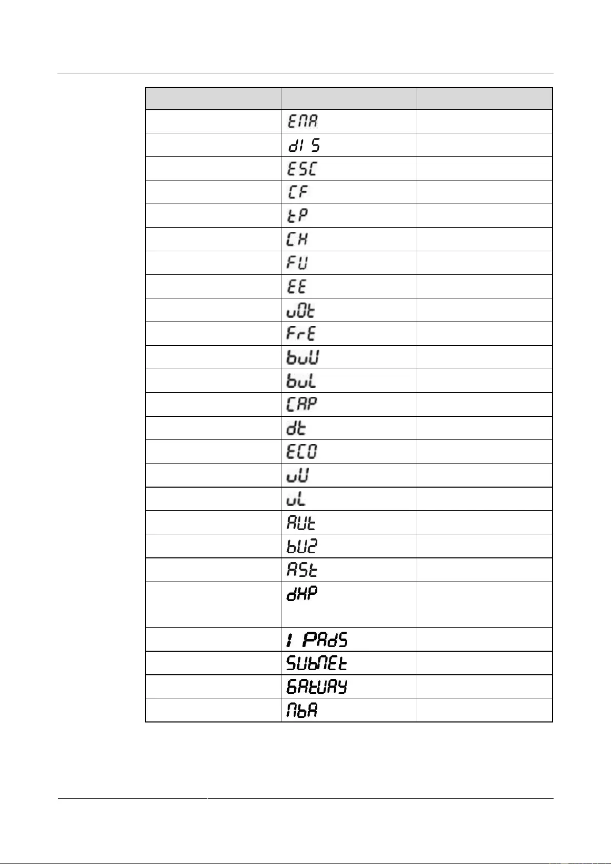
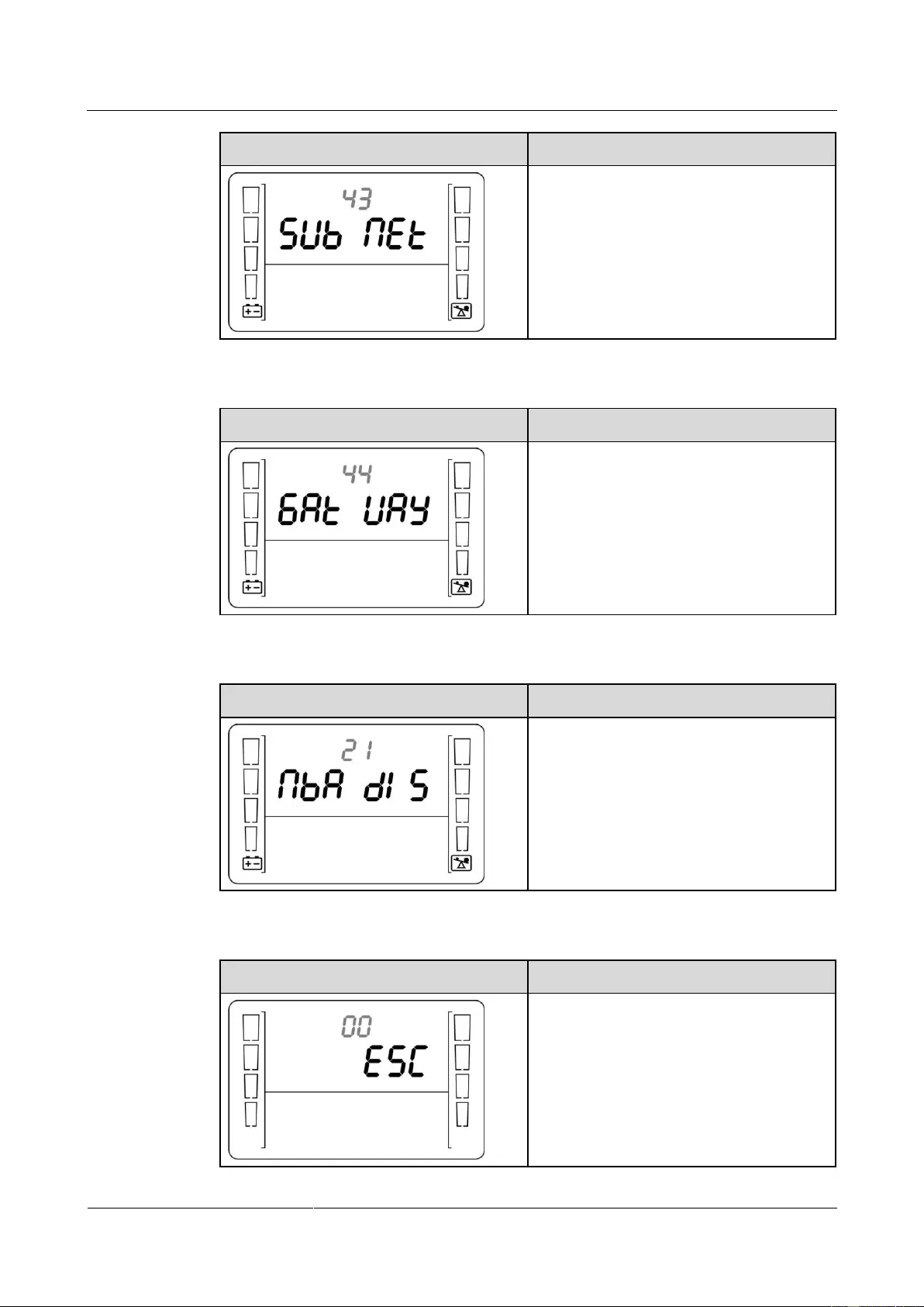
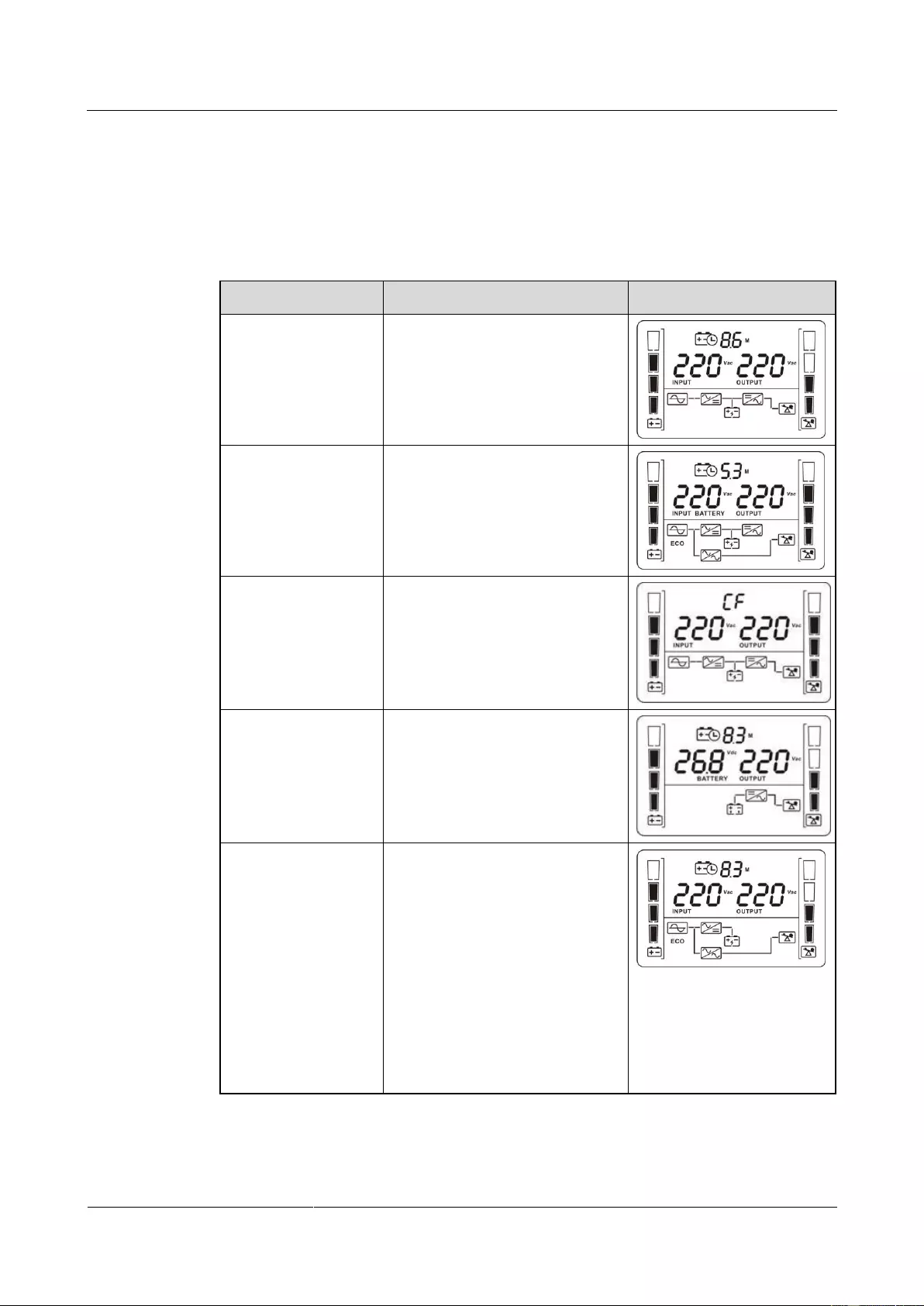
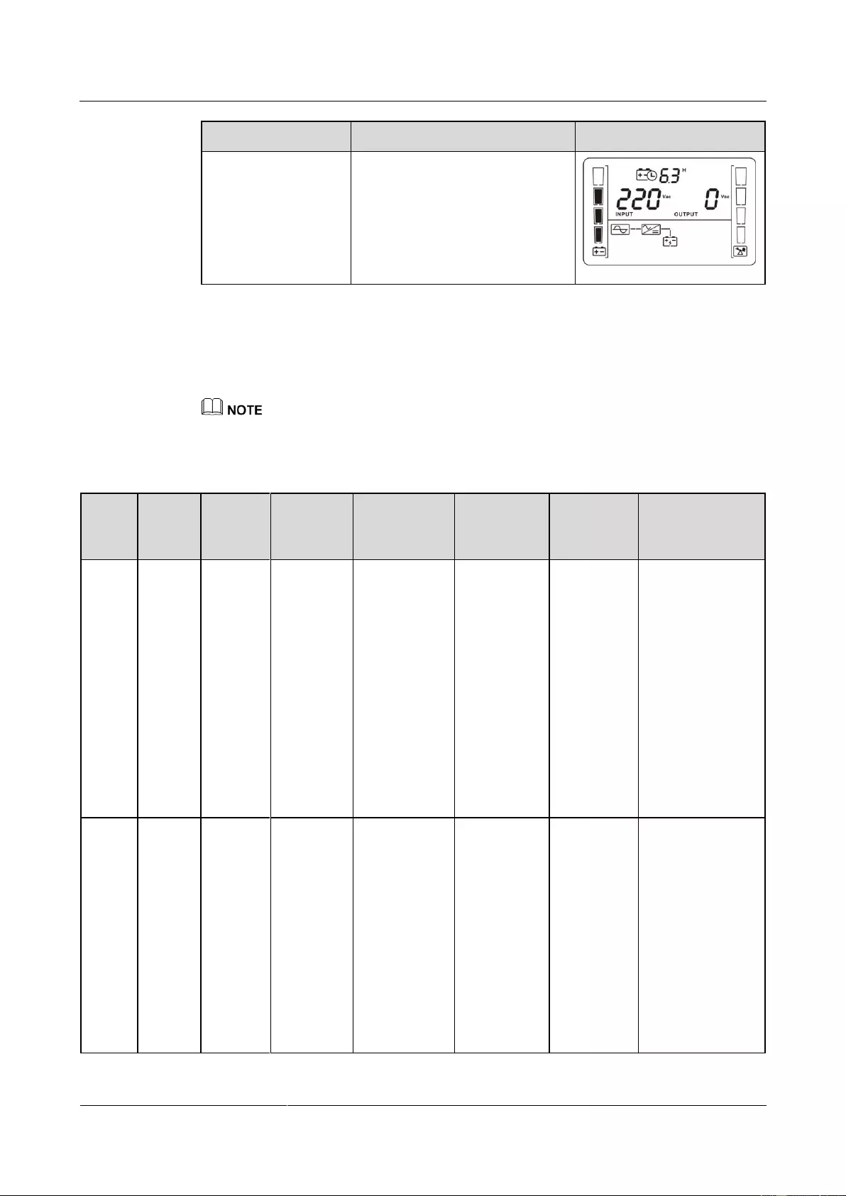
ECO mode High voltage Low voltage Constant-frequency mode Buzzer off Automatic startup Dynamic Host Configuration Protocol (DHCP) IP ADS IP address SUB NET Subnet mask GAT UAY Gateway No battery alarm disabled Issue 15 (2019-12-19) Copyright © Huawei Technologies Co., Ltd. -
Page 42: Buttons
UPS to enter the standby mode or bypass mode (if set or enabled before). Confirming setting: During the setting of UPS parameters, press Issue 15 (2019-12-19) Copyright © Huawei Technologies Co., Ltd.
-
Page 43: Setting Parameters
The user interface (UI) snapshots in this document are taken from the software version UPS2000V200R001C01SPC300 (V2R1C1SPC30 is displayed on the NetEco; you can query the version information by choosing Maintenance > Current Version). Issue 15 (2019-12-19) Copyright © Huawei Technologies Co., Ltd.
-
Page 44
220: The output voltage is 220 V AC. 230: The output voltage is 230 V AC (default value). 240: The output voltage is 240 V AC. Enable or disable the frequency conversion mode. Display Setting Issue 15 (2019-12-19) Copyright © Huawei Technologies Co., Ltd. -
Page 45
264 V AC, and the default value is 264 V The highest input voltage in bypass mode should be higher than the highest input voltage in ECO mode. Set the lowest input voltage in bypass mode. Display Setting Issue 15 (2019-12-19) Copyright © Huawei Technologies Co., Ltd. -
Page 46
0–999: Set the battery backup time in battery mode. The value ranges from 0 minutes to 999 minutes. 0: The backup time limit is canceled (default value). Enable or disable the ECO mode. Display Setting Issue 15 (2019-12-19) Copyright © Huawei Technologies Co., Ltd. -
Page 47
Enable or disable the buzzer off function. ENA: used to enable the buzzer off function. DIS: used to disable the buzzer off function. By default, the buzzer off function is disabled. Issue 15 (2019-12-19) Copyright © Huawei Technologies Co., Ltd. -
Page 48
UPS IP address: can only be displayed but not configurable. Press ▲ or ▼ to switch between different screens. On the ESC screen, press OFF/ENTER to exit. (The default value is 192.168.0.10.) Subnet mask display Issue 15 (2019-12-19) Copyright © Huawei Technologies Co., Ltd. -
Page 49
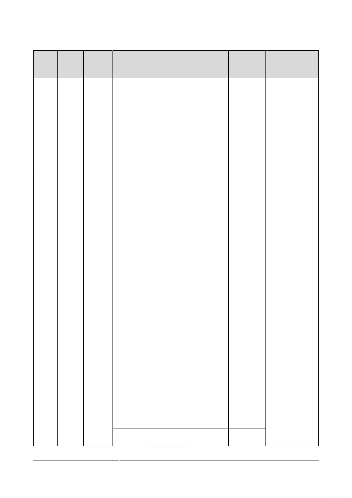
ENA: Disables the function for reporting the no battery alarm. DIS: Enables the function for reporting the no battery alarm (default value). Exit setting Display Remarks Exit from the parameter settings screen. Issue 15 (2019-12-19) Copyright © Huawei Technologies Co., Ltd. -
Page 50: Operating Modes
If the UPS is set to be enables the bypass mode, the UPS automatically transfers to bypass mode after connecting to the mains. When the UPS works in bypass mode, the buzzer beeps once every 10 seconds. Issue 15 (2019-12-19) Copyright © Huawei Technologies Co., Ltd.
-
Page 51: Alarm Handing
If yes, has no change the range output. or wait until the bypass input Issue 15 (2019-12-19) Copyright © Huawei Technologies Co., Ltd.
-
Page 52
This alarm is Batteries are The power Possible cause: disconne automatically supply from No batteries cted cleared. connected, the UPS is are connected. connected Measure: improperly, affected. Connect or damaged. batteries. Issue 15 (2019-12-19) Copyright © Huawei Technologies Co., Ltd. -
Page 53
batteries are batteries disconnected. connecte d during running of the UPS, the transfers bypass mode. Minor This alarm is The voltage The UPS automatically of each automatical Issue 15 (2019-12-19) Copyright © Huawei Technologies Co., Ltd. -
Page 54
UPS fails to Measure: start. Connect to the mains in batteries non-battery test state. connecte d during running of the UPS, the transfers bypass Issue 15 (2019-12-19) Copyright © Huawei Technologies Co., Ltd. -
Page 55
40º C. state and exceeds 40º C cannot start. when the UPS is in standby mode. As a result, the UPS cannot start. Measure: Lower the ambient temperature at Issue 15 (2019-12-19) Copyright © Huawei Technologies Co., Ltd. -
Page 56
Huawei technical support. Internal Critical This alarm The bus If this alarm Possible cause: fault must be voltage is is generated The hardware manually lower than during the Issue 15 (2019-12-19) Copyright © Huawei Technologies Co., Ltd. -
Page 57
75% of the the UPS, rated output the UPS voltage, and transfers to the output bypass current is mode. Issue 15 (2019-12-19) Copyright © Huawei Technologies Co., Ltd. -
Page 58
Measure: value of the the UPS, Contact the positive bus the UPS dealer or voltage and transfers to Huawei that of the bypass technical negative bus mode. support. voltage is Issue 15 (2019-12-19) Copyright © Huawei Technologies Co., Ltd. -
Page 59
The charger The power Possible cause: fault automatically has no supply from The internal cleared. output. the UPS is connection of the charger is affected. abnormal. Measure: Contact the dealer or Issue 15 (2019-12-19) Copyright © Huawei Technologies Co., Ltd. -
Page 60
UPS with a the rated If the UPS with a larger load. capacity. In normal transfers mode, from when the normal bypass mode to Issue 15 (2019-12-19) Copyright © Huawei Technologies Co., Ltd. -
Page 61
UPS with a UPS with a larger capacity. Minor This alarm is The UPS If the Possible cause: bypass automatically transfers to bypass is The inverter is cleared. bypass abnormal, not started. Issue 15 (2019-12-19) Copyright © Huawei Technologies Co., Ltd. -
Page 62
If the mains input is abnormal, wait for the mains to recover. Possible cause: The battery self-check is in progress. Measure: Check whether the battery self-check is in Issue 15 (2019-12-19) Copyright © Huawei Technologies Co., Ltd. -
Page 63: Alarm Indication
4.8 Alarm Indication Table 4-7 Alarm indication Alarm Display (Blinking) Buzzer Insufficient battery capacity Beeps once every second. Overload Beeps twice every second. Battery disconnection Beeps once every second. Issue 15 (2019-12-19) Copyright © Huawei Technologies Co., Ltd.
-
Page 64
UPS2000-G-(1 kVA-3 kVA) User Manual 4 Setting Control Panel Alarm Display (Blinking) Buzzer Overcharge Beeps once every second. Issue 15 (2019-12-19) Copyright © Huawei Technologies Co., Ltd. -
Page 65: Operations
The input voltage rang for the mains to start the UPS is 120–280 V AC (or 80–280 V AC after the UPS powers on). The battery voltage range is (Number of batteries x 10.8) to (Number of batteries x 14) V DC. 5.2 Starting the UPS Issue 15 (2019-12-19) Copyright © Huawei Technologies Co., Ltd.
-
Page 66
Procedure: After power on the UPS, it enters standby mode, as shown in Figure 5-1. Hold down the SELECT button for 5 seconds. The UPS enters the preset mode. Issue 15 (2019-12-19) Copyright © Huawei Technologies Co., Ltd. -
Page 67
The default value is 18 Ah for the UPS with long backup time, and the value can range from 18 Ah to 999 Ah. Figure 5-4 Setting the battery capacity Start the UPS to inverter mode. Issue 15 (2019-12-19) Copyright © Huawei Technologies Co., Ltd. -
Page 68: Shutting Down The Ups
UPS enter the invert mode. 5.6 Transferring to Battery Self-check In normal mode, ECO mode, or frequency conversion mode, hold down ON/MUTE for more than 5 seconds to enter the battery self-check test. Issue 15 (2019-12-19) Copyright © Huawei Technologies Co., Ltd.
-
Page 69: Enabling Or Disabling The Buzzer
5.9 Entering Alarm Cause ID Screen Hold down SELECT and OFF/ENTER both for 5 seconds to enter the alarm cause ID screen. Press ON/MUTE to view the previous option. Press SELECT to view the next option. Issue 15 (2019-12-19) Copyright © Huawei Technologies Co., Ltd.
-
Page 70: Maintenance And Storage
Table 6-1 UPS charging during storage Storage Temperature Charge Interval Charge Duration –25° C to +40° C Three months 1–2 hours 40° C to 45° C Two months 1–2 hours Issue 15 (2019-12-19) Copyright © Huawei Technologies Co., Ltd.
-
Page 71: Routine Maintenance
Check that all units If an alarm is Monthly are operating present, rectify the properly by fault by checking the observing the status device status and icons on the LCD, parameters. Issue 15 (2019-12-19) Copyright © Huawei Technologies Co., Ltd.
-
Page 72: Battery Maintenance
When moving batteries, avoid handling the battery upside down, handle batteries gently, and pay attention to personal safety. Keep the battery switch off when installing or maintaining the batteries. Issue 15 (2019-12-19) Copyright © Huawei Technologies Co., Ltd.
-
Page 73
5. Batteries are not deformed or bulged. 1. The ambient 1. Identify the Battery operating Monthly battery cause of the temperature temperature is abnormal battery 25± 5° C. operating Issue 15 (2019-12-19) Copyright © Huawei Technologies Co., Ltd. -
Page 74
1. Install the Battery temperature The difference Quarterly temperature sensor measurement between the sensor in the accuracy temperature correct position. measured by the temperature sensor 2. Replace the and the temperature battery Issue 15 (2019-12-19) Copyright © Huawei Technologies Co., Ltd. -
Page 75
1. Each battery 1. Rectify any Battery connection Yearly terminal is abnormal reliability connected connection. reliably. (When 2. If the fault battery strings persists, contact are powered off, Huawei technical Issue 15 (2019-12-19) Copyright © Huawei Technologies Co., Ltd. -
Page 76
(A torque wrench is used for checking the torque. After checking that the battery screws meet the requirements, mark the screws for later check.) Issue 15 (2019-12-19) Copyright © Huawei Technologies Co., Ltd. -
Page 77: Troubleshooting
5 hours and then check the in specifications. battery capacity. If the battery capacity is still insufficient, contact the dealer or Huawei technical support. Batteries are faulty. Contact the dealer or Issue 15 (2019-12-19) Copyright © Huawei Technologies Co., Ltd.
-
Page 78
UPS2000-G-(1 kVA-3 kVA) User Manual 8 Troubleshooting Symptom Possible Cause Measures Huawei technical support to replace batteries. Issue 15 (2019-12-19) Copyright © Huawei Technologies Co., Ltd. -
Page 79: Specifications
Humidity 0%–95% RH (non-condensing) Altitude < 1000 m –40° C to +70° C (battery pack: –20° C to +40° C) Storage and transportation temperature Noise < 50 dBA @ 1 m Issue 15 (2019-12-19) Copyright © Huawei Technologies Co., Ltd.
-
Page 80: Mains Input Electrical Specifications
270 V AC (tolerance ± 5%, 80% < load percentage < 100%) voltage Input power factor > 0.99 (100% resistive load) Startup voltage 120 V-280 V AC Diesel generator input Minimum 1.5 times the UPS rated capacity capacity Issue 15 (2019-12-19) Copyright © Huawei Technologies Co., Ltd.
-
Page 81: Bypass Input Electrical Specifications
Crest factor A maximum of 3:1 Inverter overload capability When the ambient temperature is 0–35° C: − 105%–110%: The UPS automatically shuts down (in battery mode) or transfers to bypass Issue 15 (2019-12-19) Copyright © Huawei Technologies Co., Ltd.
-
Page 82
In frequency conversion mode, the output load is derated to 80% of the rated capacity. If the output voltage is 200 V AC or 208 V AC, the output load is derated to 80% of the rated capacity. Issue 15 (2019-12-19) Copyright © Huawei Technologies Co., Ltd. -
Page 83: Battery Specifications
Table 9-7 Power backup specifications of the battery pack Battery Load UPS2000-G-1KR UPS2000-G-2KR UPS2000-G-3KR Pack TL (min) TL (min) TL (min) 1 Battery 100% 15.0 group 21.0 10.0 11.0 39.0 18.0 17.0 77.0 37.0 45.0 Issue 15 (2019-12-19) Copyright © Huawei Technologies Co., Ltd.
-
Page 84: Eco Feature
2 kVA 3 kVA ECO voltage Default value: ± 22 V A (configurable on the LCD) tolerance The range is ± (13 V AC-24 V AC) ECO frequency ± 3 Hz tolerance Issue 15 (2019-12-19) Copyright © Huawei Technologies Co., Ltd.
-
Page 85: System Electrical Specifications
(EFT/B) Surge IEC61000-4-5 Power magnetic IEC61000-4-8 susceptibility (PMS) Harmonic current IEC61000-3-12 Flashing IEC61000-3-11 (input current > 16 A) Impact current (lightning IEC/EN60240-2 protection) IEC/EN61000-4-5 YD/T1095-2000 YD/T944-2007 Issue 15 (2019-12-19) Copyright © Huawei Technologies Co., Ltd.
-
Page 86: A Acronyms And Abbreviations
Electrically erasable programmable read-only memory EEPROM HTTP HTTP-Hypertext Transfer Protocol Liquid crystal display Power Factor Correction RS232 Recommend Standard 232 Simple Network Management Protocol SNMP THDv Total harmonic distortion of output voltage Issue 15 (2019-12-19) Copyright © Huawei Technologies Co., Ltd.
-
Page 87
UPS2000-G-(1 kVA-3 kVA) User Manual A Acronyms and Abbreviations Uninterruptible power system Issue 15 (2019-12-19) Copyright © Huawei Technologies Co., Ltd.
UPS2000-G-(1 kVA-3 kVA)
User Manual
HUAWEI TECHNOLOGIES CO., LTD.

Copyright © Huawei Technologies Co., Ltd.
Copyright © Huawei Technologies Co., Ltd. 2019. All rights reserved.
No part of this document may be reproduced or transmitted in any form or by any means without prior
written consent of Huawei Technologies Co., Ltd.
Trademarks and Permissions
and other Huawei trademarks are trademarks of Huawei Technologies Co., Ltd.
All other trademarks and trade names mentioned in this document are the property of their respective
holders.
Notice
The purchased products, services and features are stipulated by the contract made between Huawei and
the customer. All or part of the products, services and features described in this document may not be
within the purchase scope or the usage scope. Unless otherwise specified in the contract, all statements,
information, and recommendations in this document are provided «AS IS» without warranties, guarantees or
representations of any kind, either express or implied.
The information in this document is subject to change without notice. Every effort has been made in the
preparation of this document to ensure accuracy of the contents, but all statements, information, and
recommendations in this document do not constitute a warranty of any kind, express or implied.
Huawei Technologies Co., Ltd.
Huawei Industrial Base
Bantian, Longgang
Shenzhen 518129
People’s Republic of China
UPS2000-G-(1 kVA-3 kVA)
User Manual
Copyright © Huawei Technologies Co., Ltd.
About This Document
Purpose
This document describes the UPS2000-G-(1 kVA–3 kVA) in terms of features, performance,
appearance, structure, working principle, installation, use, operation, and maintenance. UPS is
short for uninterruptible power supply. Unless otherwise specified, UPS refers to all the
models discussed in this document.
The UPS applies only to commercial and industrial use, rather than medical facilities and life
support equipment.
The UPS is of C2 (class A). If a C2 (class A) UPS is used in residential areas, additional measures
must be taken to prevent radio frequency interferences.
Intended Audience
This document is intended for:
Sales engineers
Technical support engineers
System engineers
Hardware installation engineers
Commissioning engineers
Data configuration engineers
Maintenance engineers
Symbol Conventions
The symbols that may be found in this document are defined as follows.
Indicates an imminently hazardous situation which, if
not avoided, will result in death or serious injury.
Indicates a potentially hazardous situation which, if not
avoided, could result in death or serious injury.
UPS2000-G-(1 kVA-3 kVA)
User Manual
Copyright © Huawei Technologies Co., Ltd.
Indicates a potentially hazardous situation which, if not
avoided, may result in minor or moderate injury.
Indicates a potentially hazardous situation which, if not
avoided, could result in equipment damage, data loss,
performance deterioration, or unanticipated results.
NOTICE is used to address practices not related to
personal injury.
Calls attention to important information, best practices
and tips.
NOTE is used to address information not related to
personal injury, equipment damage, and environment
deterioration.
Change History
Changes between document issues are cumulative. The latest document issue contains all the
changes made in previous issues.
Issue 13 (2019-05-05)
Updated the section «Operating Environment.»
Issue 12 (2019-02-26)
Updated the section «Output Electrical Specifications».
Issue 11 (2018-08-29)
Updated «Buttons».
Updated the section «Alarm Handling».
Issue 10 (2018-01-16)
Added the description of device application scenarios.
Issue 09 (2017-11-27)
Updated the section «Operating Environment.»
Issue 08 (2017-08-04)
Updated the section «Alarm Handling.»
Issue 07 (2017-01-19)
Added the DHCP feature.
Added an external dry contact card.

UPS2000-G-(1 kVA-3 kVA)
User Manual
Copyright © Huawei Technologies Co., Ltd.
Issue 06 (2016-05-15)
Changed the output wiring terminals of the 3 kVA UPS to a C19 output socket.
Updated the electrical specifications.
Updated the function of the ON/MUTE button.
Added the automatic startup setting.
Updated the display of battery power backup time.
Issue 05 (2016-01-25)
Updated 06: Set the battery capacity and 07: Set the discharge time limit in 4.5 Setting
Parameters.
Added bypass overload capability
Issue 04 (2015-11-23)
Updated settings of the voltage range in ECO mode.
Added button functions for exiting parameter setting screens and alarm screen.
Issue 03 (2015-10-20)
Updated the button description.
Issue 02 (2015-08-29)
Updated the routine maintenance.
Issue 01 (2015-06-25)
This issue is the first official release.

UPS2000-G-(1 kVA-3 kVA)
User Manual
Copyright © Huawei Technologies Co., Ltd.
Contents
About This Document …………………………………………………………………………………………………….. ii
1 Precautions …………………………..……………………………………………………………………………………….. 1
1.1 Transportation …………………………………………………………………………………………………………………………………………… 1
1.2 Preparation ……………………………………………………………………………………………………………………………………………….. 1
1.3 Operating Environment………………………………………………………………………………………………………………………………. 1
1.4 Installation ……………………………………………………………………………………………………………………………………………….. 2
1.5 Operation …………………………………………………………………………………………………………………………………………………. 3
1.6 Servicing, Maintenance, and Troubleshooting ……………………………………………………….………………………………………. 3
2 Overview ……………………………………………………………………………………………………………………….. 5
2.1 Model Description …………………………………………………………………………………………………………………………………….. 5
2.2 Working Principle ……………………………………………………………………………………………………………………………………… 6
2.3 Product Structure ………………………………………………………………………………………………………………………………………. 7
2.4 Optional Components ………………………………………………………………………………………………………………………………. 10
3 Installing the UPS ……………………………………………………………………………………………………….. 13
3.1 Installation Preparations …………………………………………………………………………………………………………………………… 13
3.2 Tools ……………………………………………………………………………………………………………………………………………………… 14
3.3 Installing UPS …………………………………………………………………………………………………………………………………………. 15
3.4 Installing Cables ……………………………………………………………………………………………………………………………………… 17
3.5 Installation Verification ……………………………………………………….……………………………………………………………………. 22
4 Setting Control Panel ………………………………………………………………………………………………….. 23
4.1 LCD Panel ……………………………………………………………………………………………………………………………………………… 23
4.2 Buzzer Alarm Tones …………………………………………………………………………………………………………………………………. 25
4.3 Character Display ……………………………………………………………………………………………………………………………………. 25
4.4 Buttons …………………………………………………………………………………………………………………………………………….…….. 27
4.5 Setting Parameters …………………………………………………………………………………………………………………………………… 28
4.6 Operating Modes …………………………………………………………………………………………………………………………………….. 35
4.7 Alarm Handing………………………………………………………………………………………………………………………………………… 36
4.8 Alarm Indication ……………………………………………………….…………………………………………………………………………….. 48
5 Operations …………………………………………………………………………………………………………………… 50
5.1 Checking Before Powering On the UPS ……………………………………………………………………………………………………… 50
5.2 Starting the UPS ……………………………………………………………………………………………………………………………………… 50

UPS2000-G-(1 kVA-3 kVA)
User Manual
Copyright © Huawei Technologies Co., Ltd.
5.3 Shutting Down the UPS ……………………………………………………………………………………………………………………………. 53
5.4 Transferring to Bypass Mode …………………………………………………………………………………………………………………….. 53
5.5 Transferring from Bypass Mode to Normal Mode ………………………………………………………………………………………… 53
5.6 Transferring to Battery Self-check ……………………………………………………………………………………………………………… 53
5.7 Enabling or Disabling the Buzzer ………………………………………………………………………………………………………………. 54
5.8 Manually Clearing Alarms ………………………………………………………………………………………………………………………… 54
5.9 Entering Alarm Cause ID Screen ……………………………………………………………………………………………………………….. 54
6 Maintenance and Storage ……………………………………………………………………………………………. 55
6.1 Maintenance …………………………..……………………………………………………………………………………………………………….. 55
6.2 Storage ……………………………………………………….………………………………………………………………………………………….. 55
7 Routine Maintenance ………………………………………………………………………………………………….. 56
7.1 UPS Maintenance ……………………………………………………………………………………………………………………………………. 56
7.2 Battery Maintenance ………………………………………………………………………………………………………………………………… 57
8 Troubleshooting ………………………………………………………………………………………………………….. 62
9 Specifications ………………………………………………………………………………………………………………. 64
9.1 Physical Specifications …………………………………………………………………………………………………………………………….. 64
9.2 Environmental Specifications ……………………………………………………………………………………………………………………. 64
9.3 Mains Input Electrical Specifications ……………………………………………………….………………………………………………… 65
9.4 Bypass Input Electrical Specifications ………………………………………………………………………………………………………… 66
9.5 Output Electrical Specifications ………………………………………………………………………………………………………………... 66
9.6 Battery Specifications ………………………………………………………………………………………………………………………………. 68
9.7 ECO Feature …………………………………………………………………………………………………………………………………………… 69
9.8 System Electrical Specifications …………………………..……………………………………………………………………………………. 70
9.9 Safety Regulations and EMC …………………………………………………………………………………………………………………….. 70
A Acronyms and Abbreviations …………………………………………………………………………………….. 71

UPS2000-G-(1 kVA-3 kVA)
User Manual
Copyright © Huawei Technologies Co., Ltd.
1 Precautions
1.1 Transportation
Before transporting the UPS, pack it with original packing materials to protect it from
collision.
1.2 Preparation
The UPS may have condensation inside after it is moved from a cold environment to a
warm environment, such as an indoor environment. In this case, install the UPS after it is
completely dry. Therefore, install the UPS at least 2 hours after it is placed in the target
place.
Never install the UPS in a damp environment or a place with water nearby.
Never install the UPS in a place exposed to sunlight or with a heater nearby.
Never block or shield the air vents on the UPS shell.
1.3 Operating Environment
The UPS is used for commercial and industrial purposes only. It cannot be used as a power
supply for life support devices.
The TIER4 or TIER3 power supply architecture specified in TIA942, that is, dual power
supply routes, must be used in the power supply systems that are crucial to major economic
interests or order of public places, such as the national computing center, military command
system, emergency command center, railway signal system and control center, civil aviation
air traffic control center, airport command center, financial clearing center, and transaction
center.
Ensure that the product is used in an environment that meets the product design specifications
(including power grid, temperature, and humidity) to avoid causing malfunctions, damaging
components, or voiding the warranty.
The UPS operating environment must meet the requirements for the climate indicator,
mechanically active substance indicator, and chemically active substance indicator in ETSI
EN 300 019-1 class 3.6.
UPS2000-G-(1 kVA-3 kVA)
User Manual
Copyright © Huawei Technologies Co., Ltd.
After unpacking the UPS, you are advised to power on the UPS as soon as possible. If you
temporarily do not use the UPS, take appropriate measures to prevent moisture, dust, and
foreign matter from entering the UPS.
After unpacking batteries, you are advised to connect the battery supply as soon as
possible. If you temporarily do not use the batteries, store them in dry and clean
environments. If batteries are stored for more than 90 days, charge them in time.
Otherwise, the battery lifespan may be affected.
Do not place the device in an environment that has inflammable and explosive air or gas. Do
not perform any operation in this kind of environment.
If the valid mains voltage exceeds 320 V AC, the UPS may be damaged.
Any operation on any electrical device in an environment that has inflammable air can cause
extreme danger. Strictly obey the operating environmental requirements specified in related
use manuals when using or storing the device.
Do not place the UPS in the following environments:
The environment that is close to flammable or explosive materials, dust, corrosive gases
or dust, conductive or magnetic dust, abnormal vibration, or collision.
Rooms or outdoor environments where temperature and humidity are not controlled
(with high temperature, low temperature, moisture, direct sunlight, or heat sources).
Non-confined environment near the ocean (0–3.7 km) and indoor or semi-indoor
environment where the temperature and humidity are not controllable, such as a simple
equipment room near the ocean, citizen house, garage, corridor, direct ventilation cabinet,
house with only the roof, railway station platform, gymnasium, aquarium, and so on.
The environment that is conducive for the growth of microorganisms such as fungus or
mildew.
The environment where rodents (such as mice) and insects exist.
1.4 Installation
Never connect a device that will overload the UPS, such as a laser printer, to the output
socket of the UPS.
When routing cables, keep them away from the place where they are easily to be stepped
on or make someone stumble.
Never connect household appliances, such as a hair drier, to the output socket of the
UPS.
The power to the UPS must come from a near grounded cushion socket.
Use only power cables that comply with Verband Deutscher Electrotechniker (VDE) test
standards and Conformité Européenne (CE) certification to connect the UPS to the
indoor cushion socket. The power cable can be the main power cable for your PC.

UPS2000-G-(1 kVA-3 kVA)
User Manual
Copyright © Huawei Technologies Co., Ltd.
Use only power cables that comply with VDE test standards and CE certification to
connect a load to the UPS.
When installing the UPS, ensure that the total leakage current of the UPS and connected
loads does not exceed 3.5 mA. The recommended upstream earth leakage circuit breaker
(ELCB) is more than 30 mA.
1.5 Operation
Never disconnect the main power cable for the UPS or use the indoor cushion socket
when the UPS is running. Otherwise, the grounding for the UPS and connected loads
will become invalid.
Since the UPS contains embedded batteries, its output sockets and output terminals are
energized even if the UPS is not connected to a socket.
To completely disconnect the UPS, shut down the UPS and then unplug the power cable.
Prevent liquid or any other foreign objects entering the UPS.
1.6 Servicing, Maintenance, and Troubleshooting
Since the UPS uses dangerous voltages, only qualified personnel are allowed to maintain
the UPS.
Before any maintenance or servicing, remove embedded batteries and ensure that no
current exists, especially that no voltage exists between bus capacitors.
Batteries are allowed to be replaced only by or under the instructions of the personnel
that are familiar with batteries under safe conditions. Unauthorized personnel are not
allowed to get close to batteries.
Batteries may generate an extremely high short-circuit current due to short circuits.
Therefore, take the following preventive measures before maintaining batteries:
− Remove any metal objects from yourself, such as watches and rings.
− Use only insulated tools.
When replacing batteries, install the batteries of the same quantity and model as the old
ones.
Do not throw batteries into fire, which may cause explosion.
Do not break down or damage batteries. The electrolyte will damage your skin and eyes
once it leaks.
When replacing fuses, use the fuses with the same model and specifications as the old
ones to avoid fire disaster.
Do not disassemble the UPS.

UPS2000-G-(1 kVA-3 kVA)
User Manual
Copyright © Huawei Technologies Co., Ltd.
Electric shock risk. The UPS is still energized even if it is disconnected from the socket,
because its internal components are still connected to embedded batteries.
Electric shock risk. The battery circuit is not disconnected from the input voltage. It is
possible to have a dangerous voltage between the battery terminal and the ground cable.
Therefore, ensure that no voltage exists before touching the UPS interior.

UPS2000-G-(1 kVA-3 kVA)
User Manual
Copyright © Huawei Technologies Co., Ltd.
2 Overview
2.1 Model Description
This document discusses the following UPS models, as shown in Table 2-1.
Table 2-1 UPS models
1 K-standard
model-rack
mounted-IEC
The two models are represented by 1 kVA
in the description of their common features
and parameters.
1 K-long backup
time model-rack
mounted-IEC
2 K-standard
model-rack
mounted-IEC
The two models are represented by 2 kVA
in the description of their common features
and parameters.
2 K-long backup
time model-rack
mounted-IEC
3 K-standard
model-rack
mounted-IEC
The two models are represented by 3 kVA
in the description of their common features
and parameters.
3 K-long backup
time model-rack
mounted-IEC
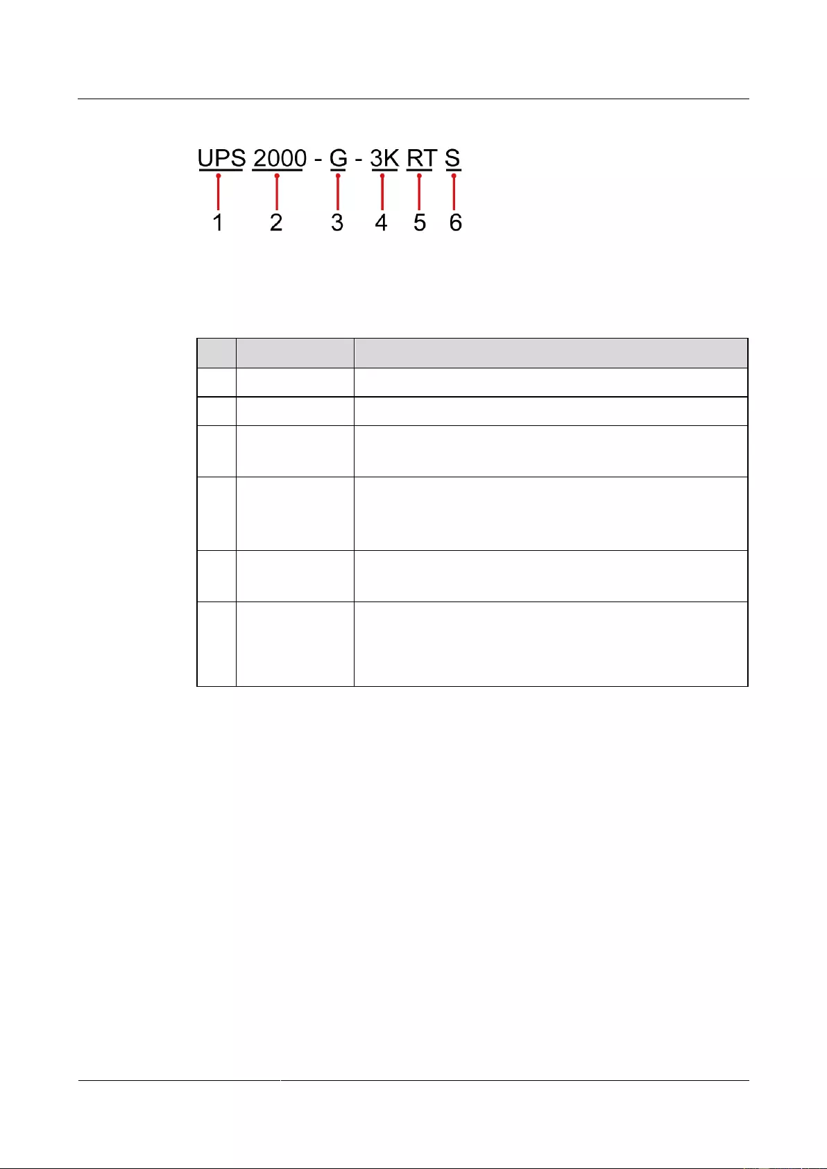
Figure 2-1 shows the UPS model number.
UPS2000-G-(1 kVA-3 kVA)
User Manual
Copyright © Huawei Technologies Co., Ltd.
Figure 2-1 UPS model number
Table 2-2 describes the UPS model number.
Table 2-2 UPS model number details
2000: P (capacity) ≤ 20 kVA
A: tower series
G: rack series
1K: 1 kVA
2K: 2 kVA
3K: 3 kVA
RT: rack- or tower-mounted UPS
TT: tower-mounted UPS
Built-in battery
pack (optional)
S: standard backup time model, which provides only a
standard battery pack
L: long backup time model. You need to use an external
large-capacity battery pack
2.2 Working Principle
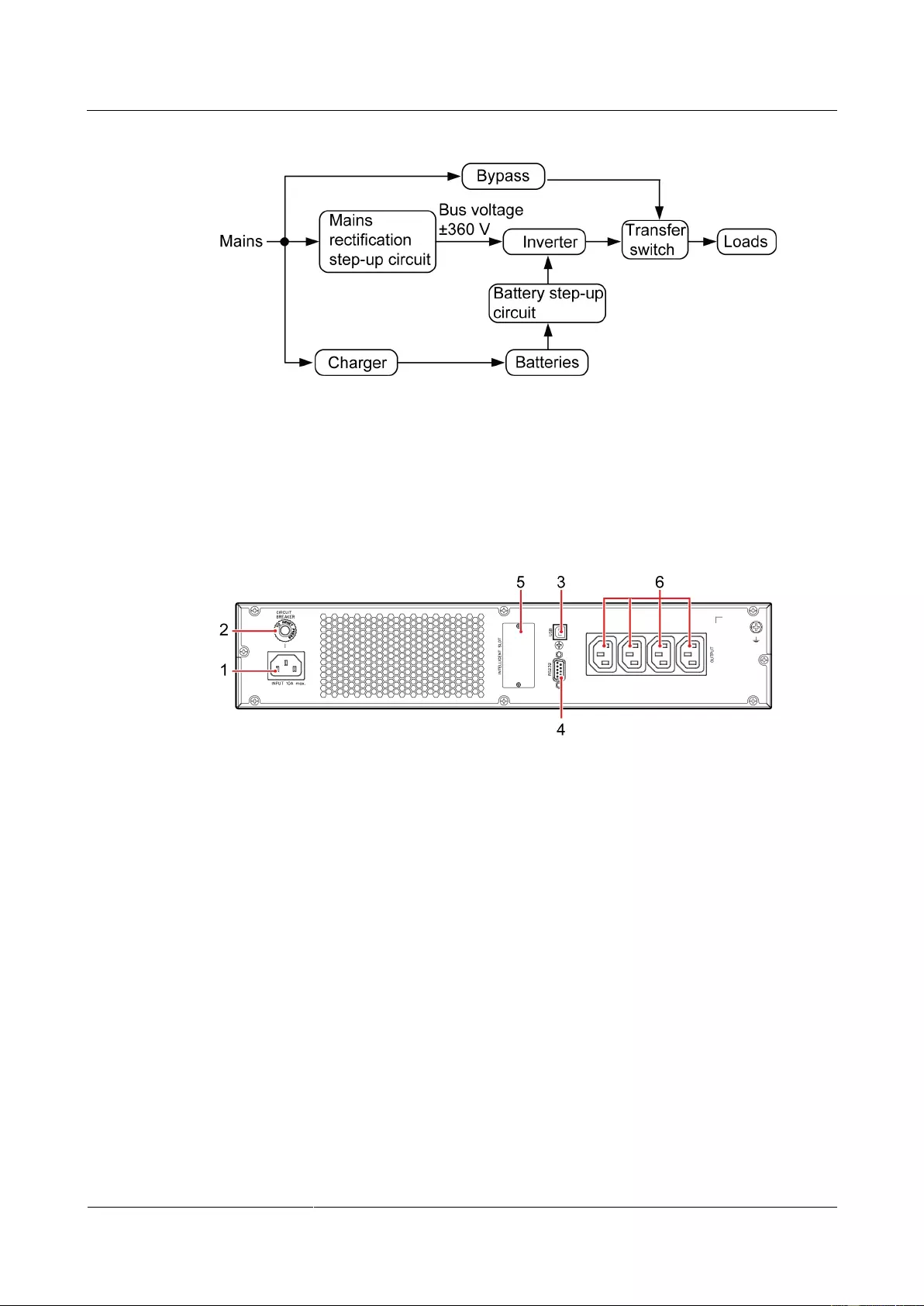
Figure 2-2 shows the UPS conceptual diagram.
UPS2000-G-(1 kVA-3 kVA)
User Manual
Copyright © Huawei Technologies Co., Ltd.
Figure 2-2 UPS conceptual diagram
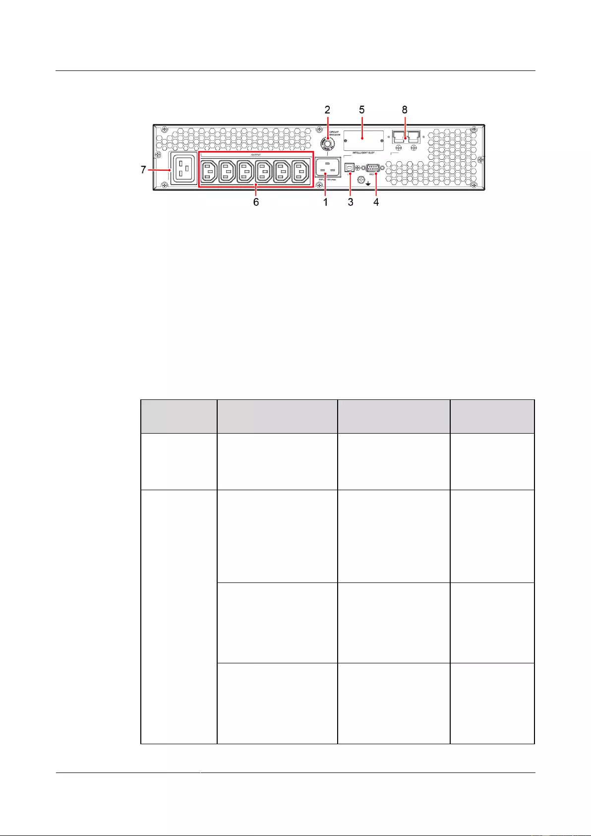
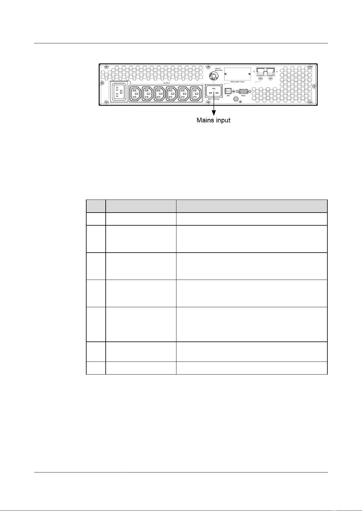
2.3 Product Structure
Figure 2-3toFigure 2-8 show the rear view of the 1 kVA, 2 kVA, and 3 kVA UPSs.
Figure 2-3 Rear view of UPS2000-G-1KRTS
(1) Mains input socket (C14)
(2) Input circuit
breaker
(3) Universal serial bus (USB) port (security protection mechanism
supported)
UPS2000-G-(1 kVA-3 kVA)
User Manual
Copyright © Huawei Technologies Co., Ltd.
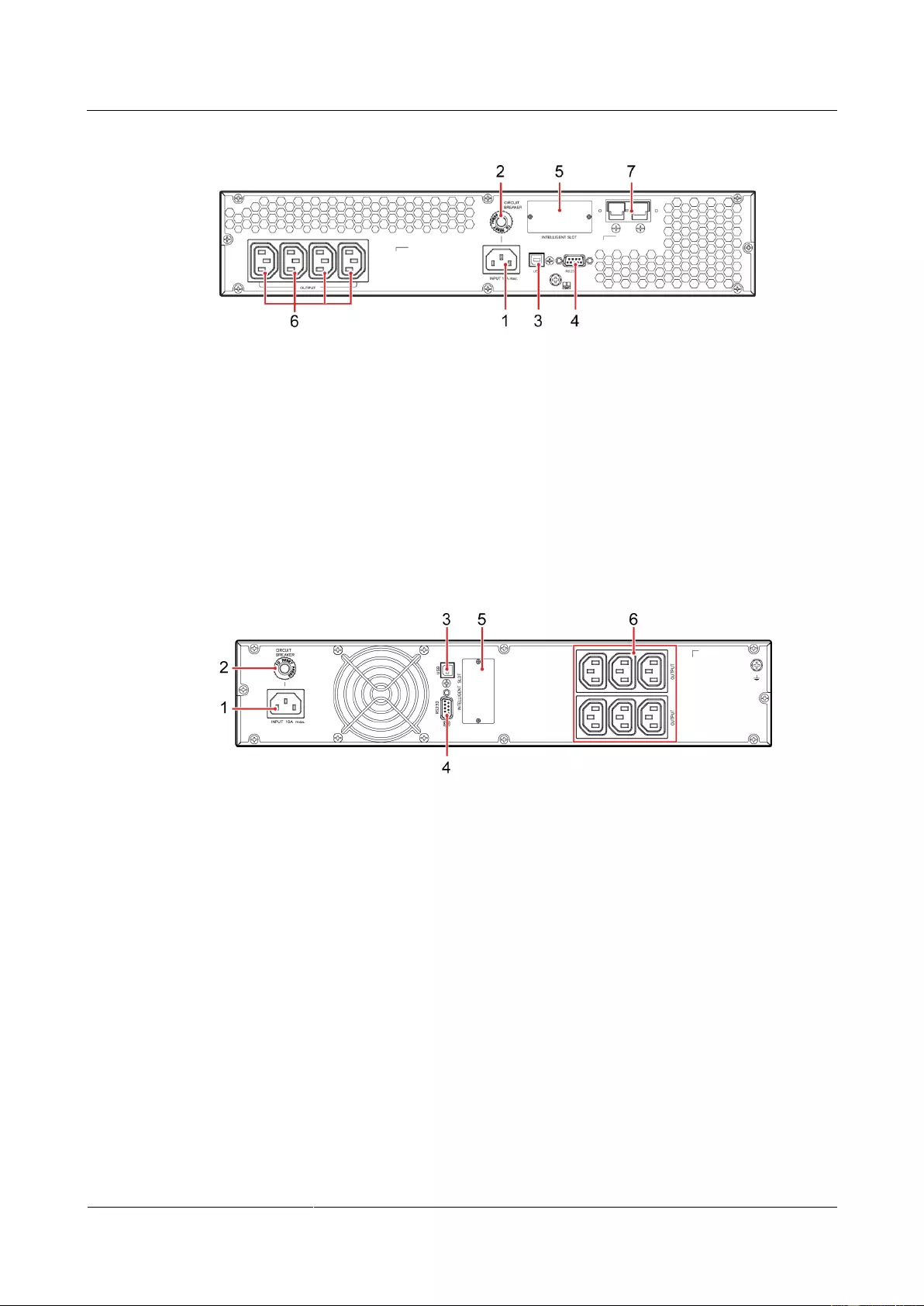
Figure 2-4 Rear view of UPS2000-G-1KRTL
(1) Mains input socket (C14)
(2) Input circuit
breaker
(3) USB port (security protection mechanism supported)
(7) External battery connector (only for long backup time
models)
Figure 2-5 Rear view of UPS2000-G-2KRTS
(1) Mains input socket (C14)
(2) Input circuit breaker
(3) USB port (security protection mechanism supported)
UPS2000-G-(1 kVA-3 kVA)
User Manual
Copyright © Huawei Technologies Co., Ltd.
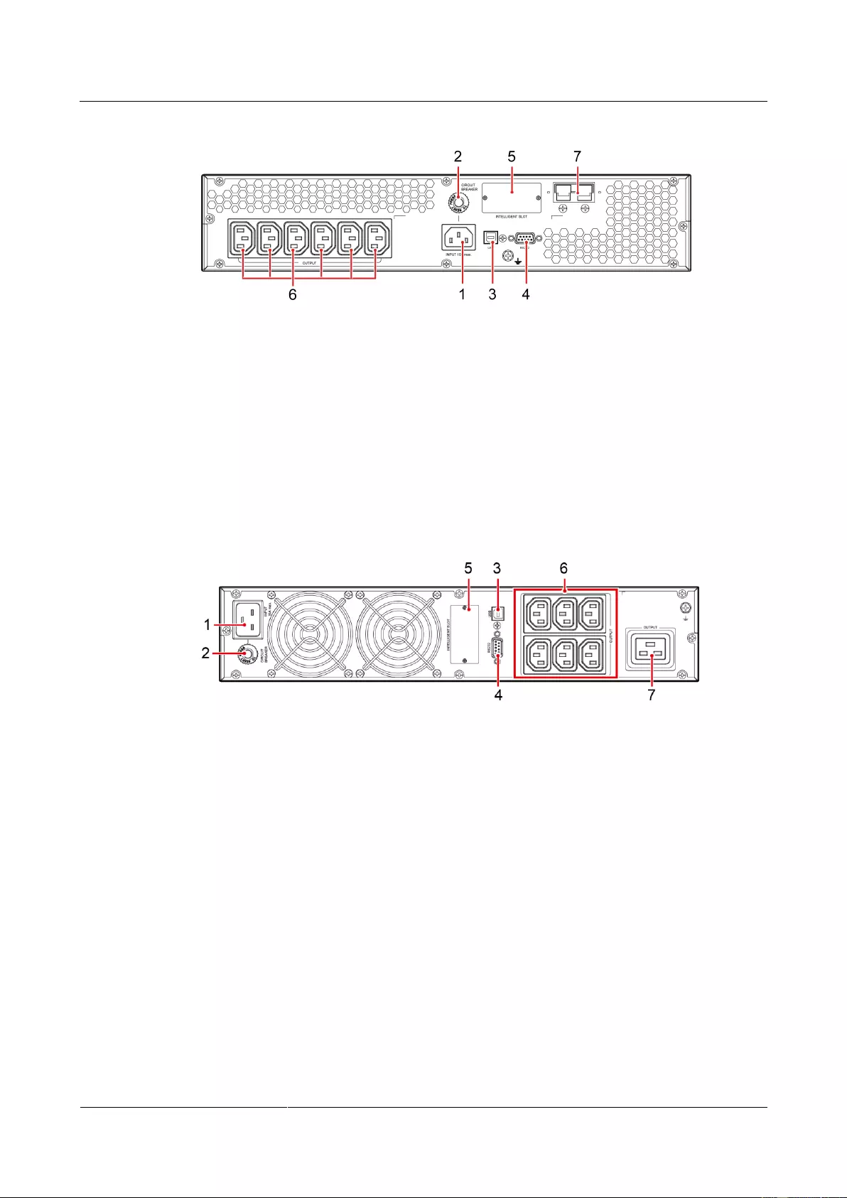
Figure 2-6 Rear view of UPS2000-G-2KRTL
(1) Mains input socket (C14)
(2) Input circuit
breaker
(3) USB port (security protection mechanism supported)
(7) External battery connector (only for long backup time
models)
Figure 2-7 Rear view of UPS2000-G-3KRTS
(1) Mains input socket (C20)
(2) Input circuit breaker
(3) USB port (security protection mechanism supported)
UPS2000-G-(1 kVA-3 kVA)
User Manual
Copyright © Huawei Technologies Co., Ltd.
Figure 2-8 Rear view of UPS2000-G-3KRTL
(1) Mains input socket (C20)
(2) Input circuit breaker
(3) USB port (security protection
mechanism supported)
(8) External battery connector (only for long
backup time models)
2.4 Optional Components
Ambient
temperature
and humidity
sensor
Measures the UPS
ambient temperature
(0–50°C) and humidity
(0%–100% RH).
Used together
with an SNMP
card.
Contains two battery
strings. Each string
contains three 9 Ah/12
V DC batteries. The
output voltage of the
battery pack is 36 V
DC.
Applicable to the
1 kVA UPS with
long backup
time.
Contains one battery
string with six 9 Ah/12
V DC batteries. The
output voltage of the
battery pack is 72 V
DC.
Applicable to the
2 kVA UPS with
long backup
time.
Contains one battery
string with eight 9
Ah/12 V DC batteries.
The output voltage of
the battery pack is 96 V
DC.
Applicable to the
3 kVA UPS with
long backup
time.

UPS2000-G-(1 kVA-3 kVA)
User Manual
Copyright © Huawei Technologies Co., Ltd.
Monitors the UPS and
provides the Ethernet
networking solution. It
also enables ambient
temperature and
humidity detection.
Provides two cascaded
RJ45 ports to
implement networking
over the Modbus or
YDN-23 protocol.
Provides dry contact
signals and manages the
UPS remotely.
External dry
contact card
Provides dry contact
signals and monitors the
UPS remotely.
Used together
with an SNMP
card.
Connects the battery
pack or rack to the
mains and charges the
batteries or battery
pack.
Applicable to the
1 kVA UPS with
long backup
time.
Applicable to the
2 kVA UPS with
long backup
time.
Applicable to the
3 kVA UPS with
long backup
time.
The OVCD is
connected between the
mains and the UPS
input. If the mains
voltage is abnormally
high, the OVCD
actively disconnects the
L wire between the
mains input and UPS to
prevent the abnormally
high voltage from
flowing into the UPS
and damaging the UPS.
In addition, the OVCD
provides extra input
surge voltage absorbing
capability and input

UPS2000-G-(1 kVA-3 kVA)
User Manual
Copyright © Huawei Technologies Co., Ltd.
Secures the UPS or
battery pack.
Configured in
rack-mounted
scenarios.

UPS2000-G-(1 kVA-3 kVA)
User Manual
Copyright © Huawei Technologies Co., Ltd.
3 Installing the UPS
3.1 Installation Preparations
Floor Loading Capacity
The floor can bear the weight of the UPS and its optional components. In the case of rack
installation, ensure that the floor can also bear the weight of the rack.
Installation Requirements
Do not install the UPS in high temperature, low temperature, and damp areas.
The installation position is far away from water sources, heat sources, and inflammable
materials. The UPS is free from direct sunlight, dust, volatile gases, corrosive materials,
and salty air.
Do not install the UPS in environments with conductive metal scraps in the air.
The optimal operating temperatures for batteries are 20–30°C. Operating temperatures
higher than 30°C shorten the battery lifespan, and operating temperatures lower than
20°C reduce the battery backup time.
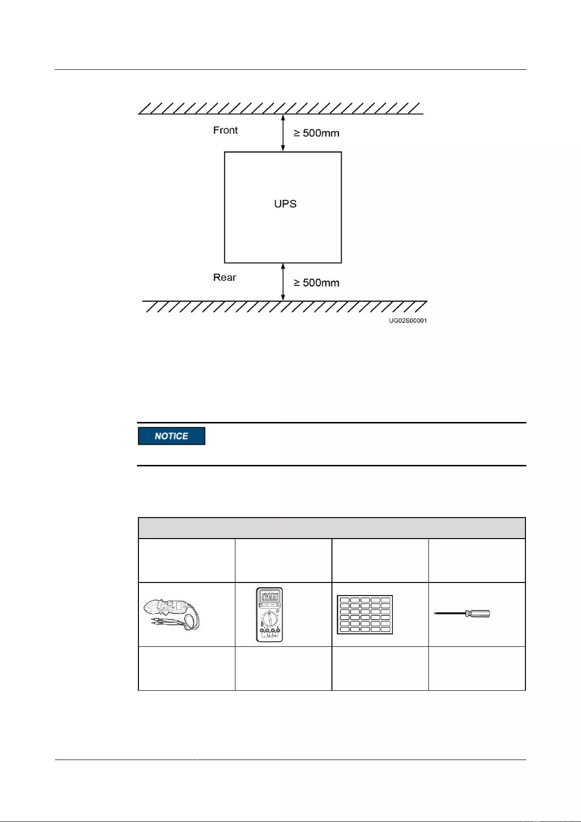
Dimensions
The space allocated for UPS installation has the combined dimensions of the UPS and its
input and output socket installed on the rear panel. The depth of the space is the depth of
the UPS plus about 100 mm.
Reserve a clearance of at least 500 mm respectively from the front and rear panels of the
UPS to the wall or adjacent equipment to facilitate ventilation and heat dissipation.
UPS2000-G-(1 kVA-3 kVA)
User Manual
Copyright © Huawei Technologies Co., Ltd.
Figure 3-1 Reserved clearances
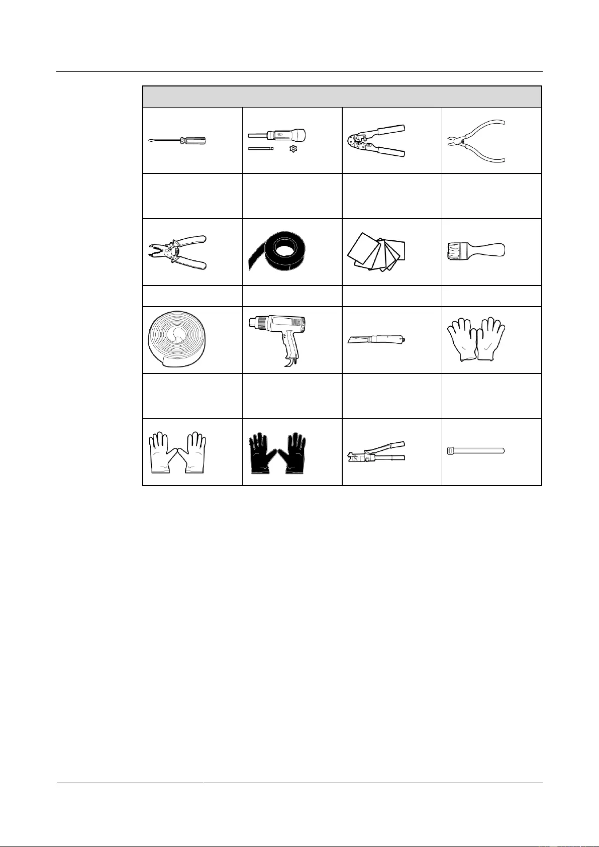
3.2 Tools
Get tools insulated to prevent electric shocks.
Table 3-1 lists the tools that may be used during installation.
Table 3-1 Tools
Appearance, Specifications, and Name
Phillips screwdriver
(PH2 x 150 mm or
PH3 x 250 mm)
Flat-head
screwdriver (2 mm x
80 mm)
UPS2000-G-(1 kVA-3 kVA)
User Manual
Copyright © Huawei Technologies Co., Ltd.
Appearance, Specifications, and Name
Polyvinyl chloride
(PVC) insulation
tape
Electrostatic
discharge (ESD)
gloves
3.3 Installing UPS
The UPS can be installed on a desk or in a 19-inch rack. 1 kVA UPS, 2 kVA UPS, and 3 kVA
UPS need 2 U space separately. The installation method for 1 kVA UPS, 2 kVA UPS and 3
kVA UPS are the same. The figures in this chapter based on the 3 kVA UPS.
Rack-mounting a UPS
1. Take out mounting brackets from the fitting bag, and install mounting brackets on UPS.
2. Install guide (2 U) on the Cabinet. Then Place the UPS on the guide rails.

UPS2000-G-(1 kVA-3 kVA)
User Manual
Copyright © Huawei Technologies Co., Ltd.
Figure 3-2 Rack-mounting the UPS
Tower-mounting a UPS
1. Remove the UPS front panel.
2. Rotate the control panel 90 degrees clockwise.
3. Rotate the logo 90 degrees clockwise on the front panel. Reinstall the front panel.
4. Assemble support bases. The minimum distance between two support bases should be
150 mm.
5. Place UPS on the support bases in sequence.
6. Adjust the UPS and the support bases to be horizontally.
Figure 3-3 Tower—mounting the UPS
Figure 3-4 Tower—mounting the UPS
UPS2000-G-(1 kVA-3 kVA)
User Manual
Copyright © Huawei Technologies Co., Ltd.
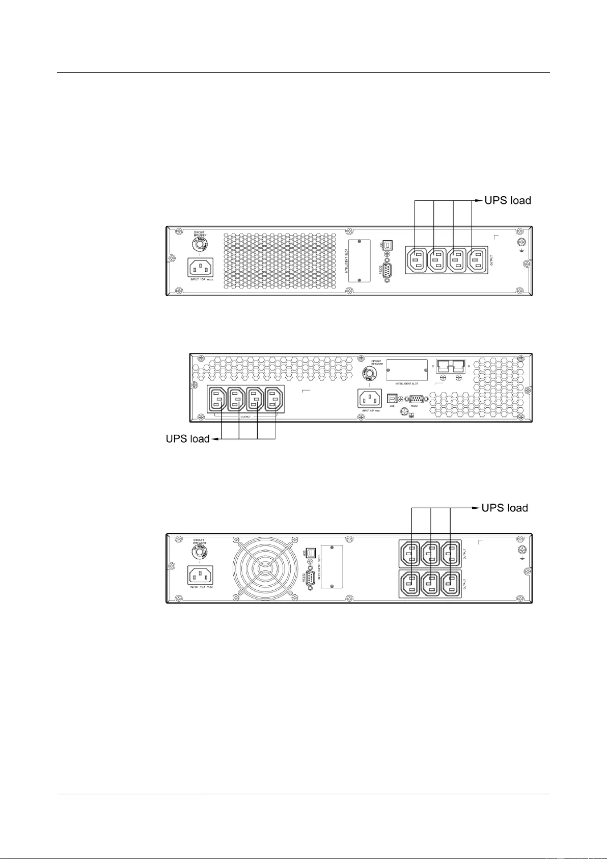
3.4 Installing Cables
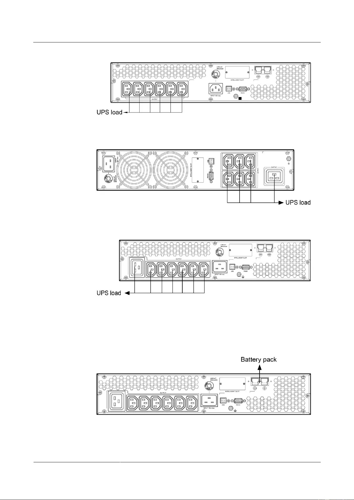
1. Connect the UPS output power cable.
For socket-type output, connect loads to the UPS output sockets. When a power failure
occurs, the UPS automatically supplies power to the loads.
Figure 3-5 Connecting cables to the 1KRTS UPS output
Figure 3-6 Connecting cables to the 1KRTL UPS output
Figure 3-7 Connecting cables to the 2KRTS UPS output
UPS2000-G-(1 kVA-3 kVA)
User Manual
Copyright © Huawei Technologies Co., Ltd.
Figure 3-8 Connecting cables to the 2KRTL UPS output
Figure 3-9 Connecting cables to the 3KRTS UPS output
Figure 3—10 Connecting cables to the 3KRTL UPS output
2. Connecting battery power cables to a long backup time model. (The step is optional for
long backup time model, the standard model with built-in batteries cannot support
external batteries.)
Figure 3—11 Connecting cables to the 3 kVA UPS battery pack
UPS2000-G-(1 kVA-3 kVA)
User Manual
Copyright © Huawei Technologies Co., Ltd.
If the 1 kVA UPS with long backup time needs to connect to external battery strings, each battery
string must consist of three 12 V batteries connected in series. If the 2 kVA UPS with long backup
time needs to connect to external battery strings, each battery string must consist of six 12 V
batteries connected in series. If the 3 kVA UPS with long backup time needs to connect to external
battery strings, each battery string must consist of eight 12 V batteries connected in series.
The UPS with long backup time provides a charge current of 4 A and the current is not configurable.
If the UPS needs to connect to battery packs or battery strings, the total battery capacity must exceed
18 Ah. Otherwise, batteries may be damaged. If the capacity of external battery packs or battery
strings to be connected exceeds 40 Ah, it is recommended that an external charger be purchased to
increase the charge current. If an external charger is not purchased, the charge time will be long.
The battery pack (ESS-36V12-9*2AHBPVBB01) for 1 kVA UPS with long backup time contain two
group battery strings. The battery pack (ESS-72V12-9AHBPVBB01) for 2 kVA UPS with long
backup time only contain one group battery strings. The battery pack (ESS-96V12-9AHBPVBB02)
for 3 kVA UPS with long backup time only contain one group battery strings.
The 1 kVA UPS with long backup time is allowed a maximum of two battery packs
(ESS-36V12-9*2AHBPVBB01) in parallel. The 2 kVA UPS with long backup time is allowed a
maximum of four battery packs (ESS-72V12-9AHBPVBB01) in parallel. The 3 kVA UPS with long
backup time is allowed a maximum of four battery packs (ESS-96V12-9AHBPVBB02) in parallel.
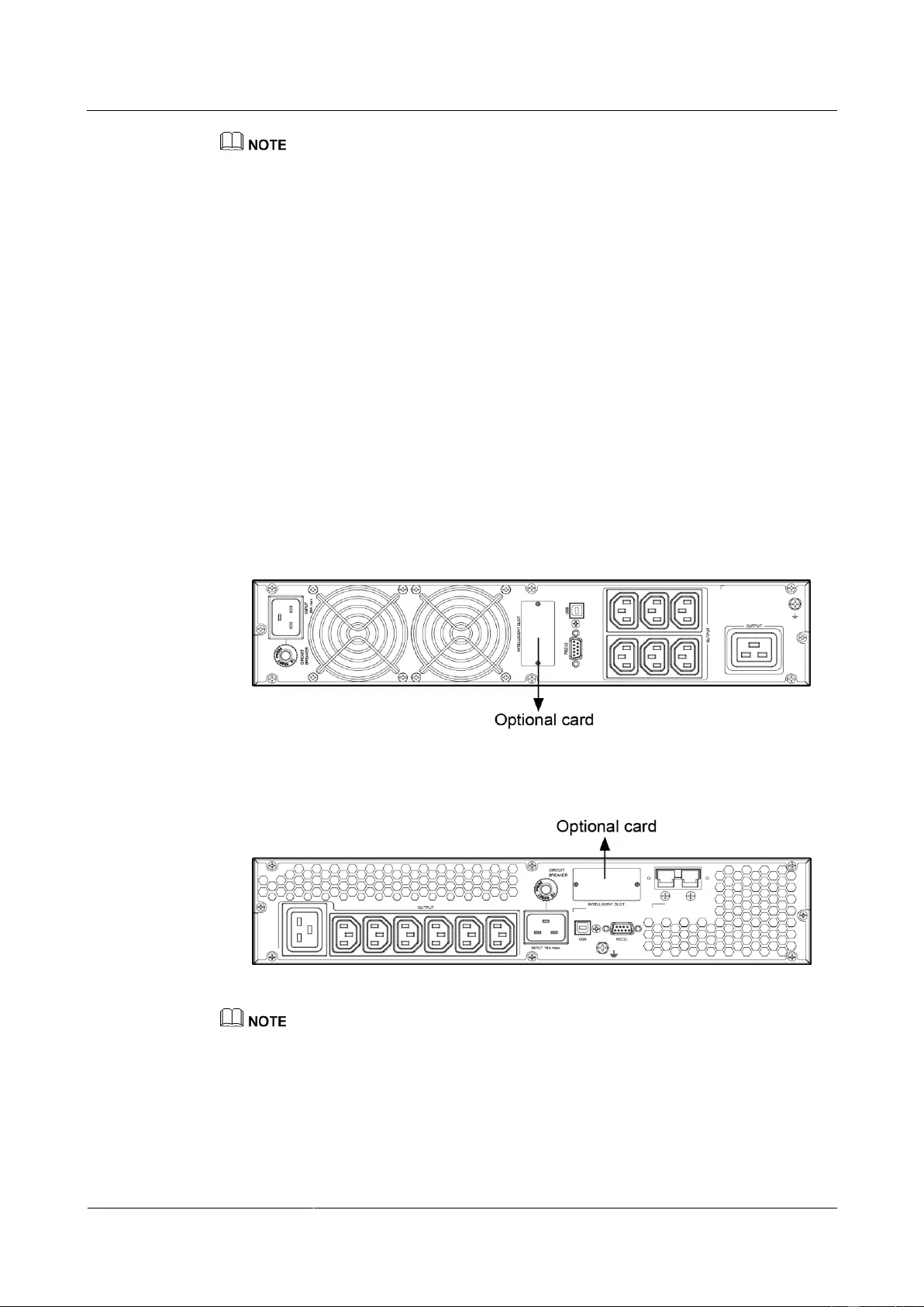
3. Install the optional communication card to the UPS. The installation method for 1 kVA
UPS, 2 kVA UPS, and 3 kVA UPS are the same. The figures below based on the 3 kVA
UPS.
Figure 3—12 Installing an optional card on the 3KRTS UPS
Figure 3—13 Installing an optional card on the 3KRTL UPS
The UPS provides an optional smart slot to support the SNMP card, dry contact card, or Modbus card.
Any of the three types of cards offers advanced communication functions and various monitoring
options.
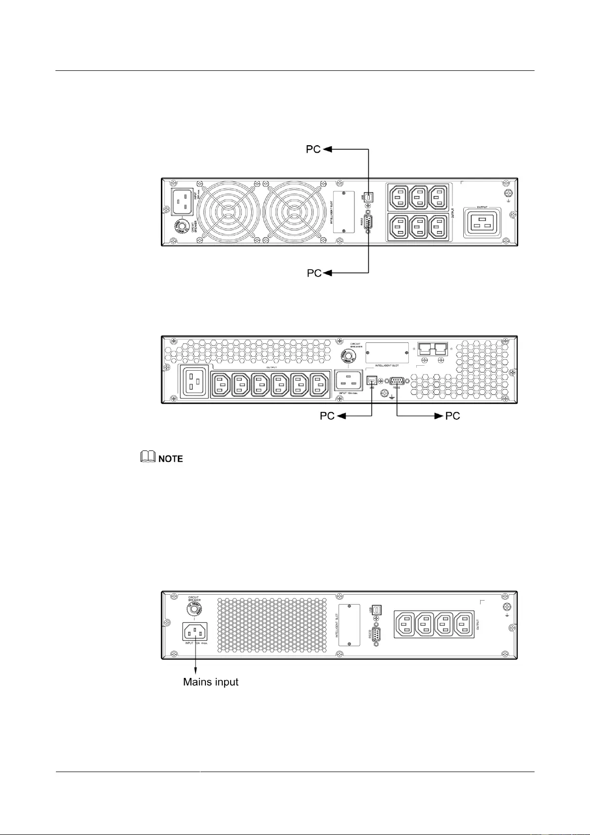
4. Connect the UPS to a PC.
Connect the UPS to the RS232 or USB port on a PC. Then you can monitor the UPS
status using the PC as long as you have installed the monitoring software. The
UPS2000-G-(1 kVA-3 kVA)
User Manual
Copyright © Huawei Technologies Co., Ltd.
installation method for 1 kVA UPS, 2 kVA UPS, and 3 kVA UPS are the same. The
figures below based on the 3 kVA UPS.
Figure 3—14 Connecting communications cables to the 3KRTS UPS
Figure 3—15 Connecting communications cables to the 3KRTL UPS
The USB channel supports a serial data communications protocol between the UPS and the PC.
If you connect a DB9 connector to the RS232 port, the UPS can communicate with the PC over
serial data.
The UPS support either USB or RS232.
To monitor the UPS over a PC, need to install the monitoring software iManager NetEco 1000U.
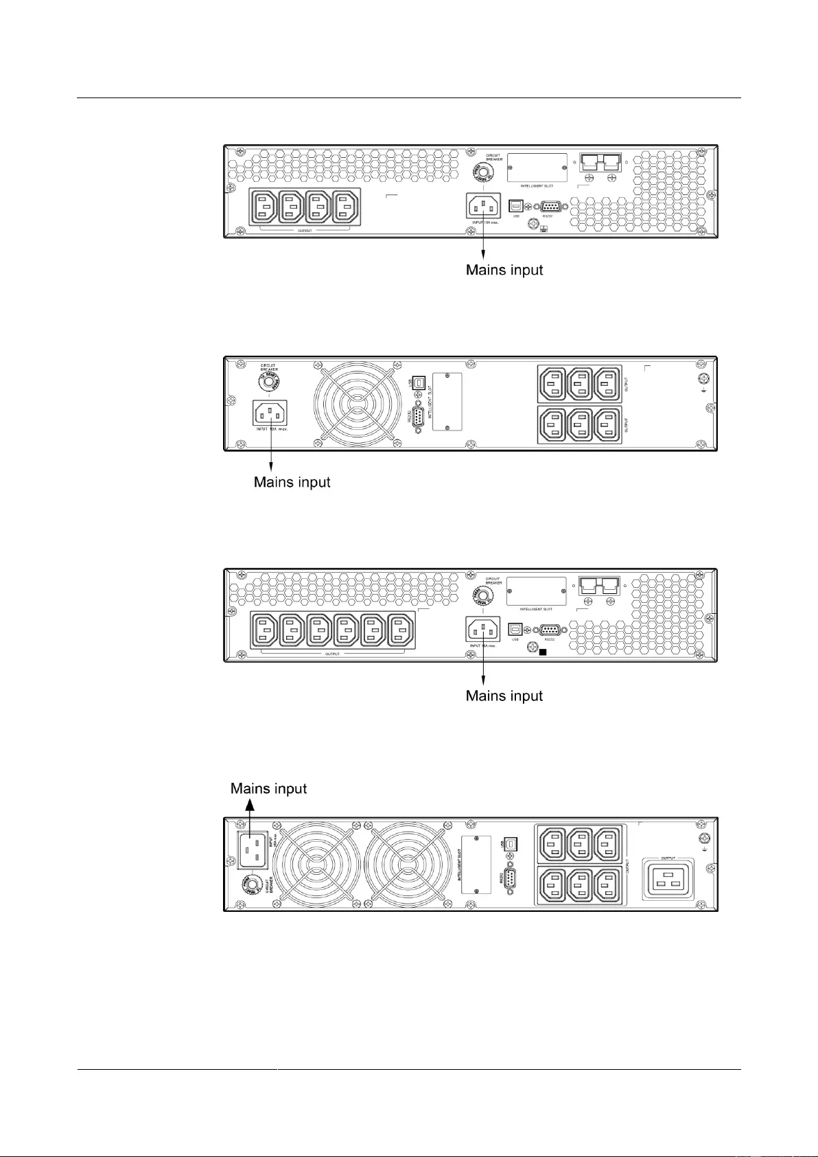
5. Take out input power cables from the fitting bag, and connect mains input power cables
to the UPS.
Figure 3—16 Connecting cables to the 1KRTS UPS input
UPS2000-G-(1 kVA-3 kVA)
User Manual
Copyright © Huawei Technologies Co., Ltd.
Figure 3—17 Connecting cables to the 1KRTL UPS input
Figure 3—18 Connecting cables to the 2KRTS UPS input
Figure 3—19 Connecting cables to the 2KRTL UPS input
Figure 3—20 Connecting cables to the 3KRTS UPS input
UPS2000-G-(1 kVA-3 kVA)
User Manual
Copyright © Huawei Technologies Co., Ltd.
Figure 3—21 Connecting cables to the 3KRTL UPS input
3.5 Installation Verification
Table 3-2 gives the installation verification checklist.
Table 3-2 Installation verification checklist
Cable routing meets engineering requirements.
Power cables and battery cables are tightened to
specified torques using a torque wrench, connected
correctly, and free of damage.
Cable connections for
USB ports and network
ports
Cables to USB ports and network ports are connected
correctly and securely.
Labels are neatly attached to both ends of each cable,
and the information on the labels is concise and
understandable.
The ground cable is securely connected to the
equipment room ground bar. Measure the resistance
between the UPS ground cable and the equipment room
ground bar, which must be less than 0.1 ohm.
Distances between cable
ties
Distances between cable ties are the same, and no burr
exists.
Clean the conductive air and other sundries.
UPS2000-G-(1 kVA-3 kVA)
User Manual
Copyright © Huawei Technologies Co., Ltd.
4 Setting Control Panel
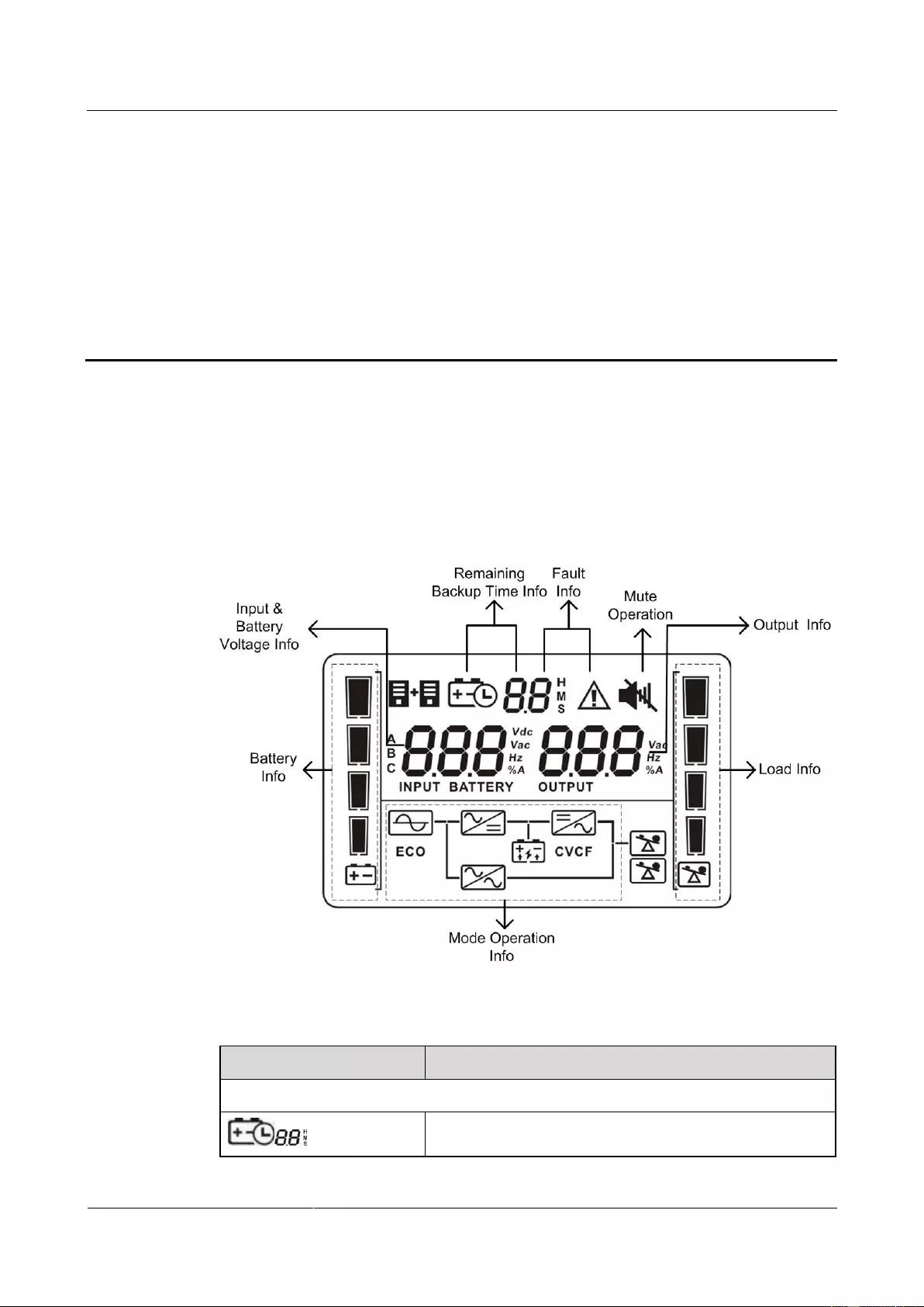
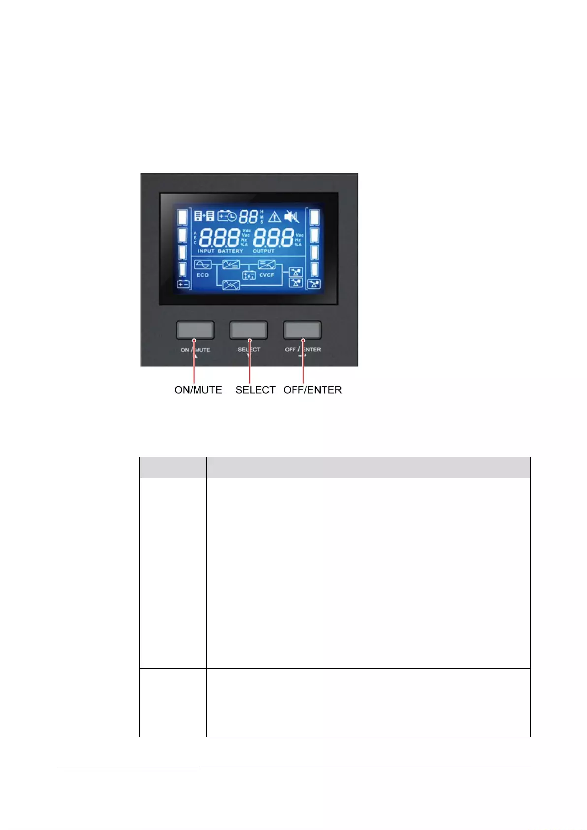
4.1 LCD Panel
The control panel is on the UPS front panel. The control panel allows you to control and
operate the UPS, view the running status, set parameters, and view alarms.
Figure 4-1 LCD panel
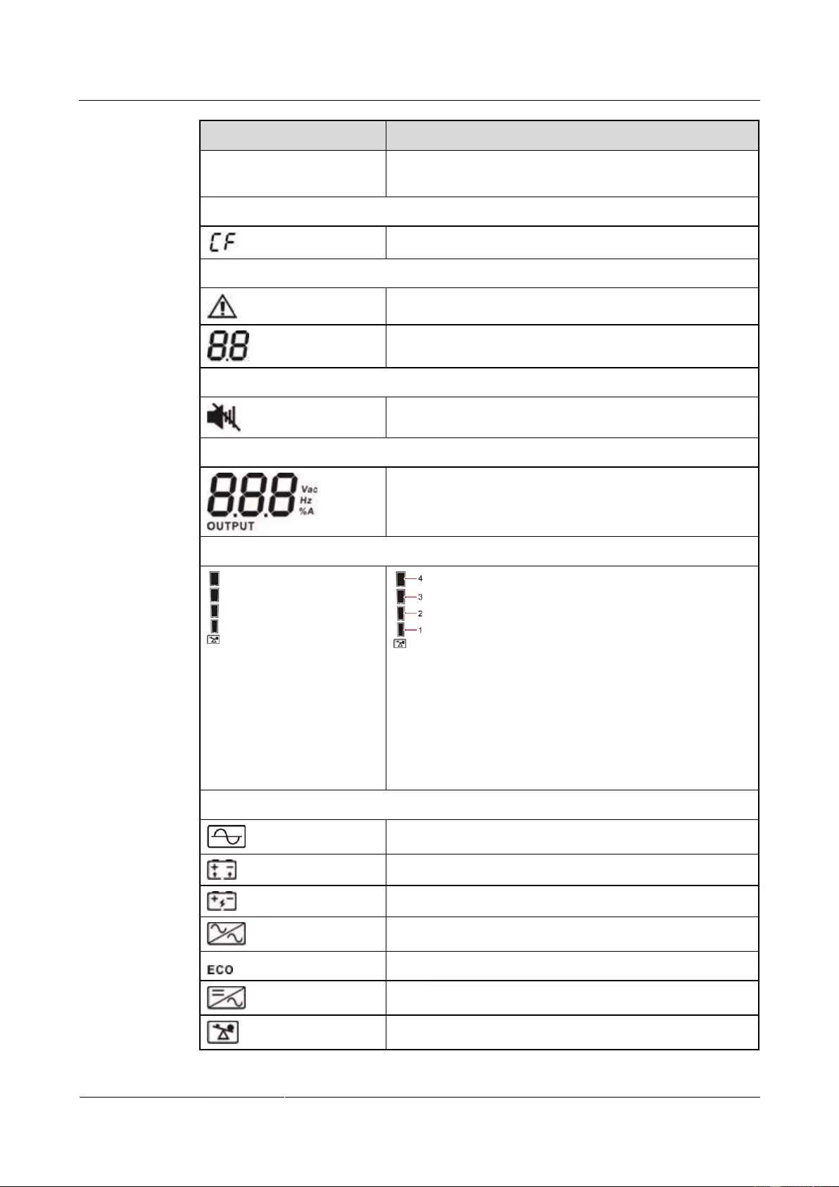
Table 4-1 Icon description
Alternately displays the remaining power backup time,
alarm ID, and CF (only displays in frequency conversion
UPS2000-G-(1 kVA-3 kVA)
User Manual
Copyright © Huawei Technologies Co., Ltd.
mode) in digits.
H: hour; M: minute; S: second
Frequency conversion mode information
Displays that the UPS is in frequency conversion mode.
Indicates that an alarm occurs.
Indicates the warning or alarm ID.
Displays the output voltage, frequency, or battery voltage.
Vac: output voltage; Hz: output frequency; %: output load
ratio; A: output current
Displays the current load percentage by level:
[0–25%]: Indicator 1 is steady on.
(25%–50%]: Indicators 1 and 2 are steady on.
(50%–75%]: Indicators 1, 2 and 3 are steady on.
(75%–100%]: Indicators 1, 2, 3 and 4 are steady on.
> 100%: Indicators 1, 2, 3 and 4 are blink.
Mode operating information
Indicates that the UPS has connected to the mains.
Indicates that batteries are supplying power.
Indicates that batteries are being charged.
Displays that the UPS is in bypass mode.
Displays that the UPS is in ECO mode.
Indicates that the frequency conversion circuit is working.
Displays that the output socket is delivering power output.
UPS2000-G-(1 kVA-3 kVA)
User Manual
Copyright © Huawei Technologies Co., Ltd.
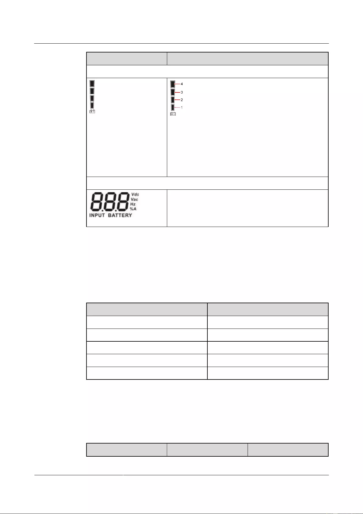
Displays the current battery capacity by level:
[0–25%]: Indicator 1 is steady on.
(25%–50%]: Indicators 1 and 2 are steady on.
(50%–75%]: Indicators 1, 2 and 3 are steady on.
(75%–100%]: Indicators 1, 2, 3 and 4 are steady on.
> 100%: Indicators 1, 2, 3 and 4 are blink.
Input voltage information
Displays the input voltage, frequency, battery voltage, or
input current percentage.
Vac: input voltage; Vdc: battery voltage; Hz: input
frequency; %A: battery capacity percentage.
4.2 Buzzer Alarm Tones
Table 4-2 describes the buzzer alarm tones.
Table 4-2 Buzzer alarm tone description
Beeps once every 4 seconds.
Beeps twice every second.
Beeps once every 10 seconds.
4.3 Character Display
Table 4-3 Character display description
UPS2000-G-(1 kVA-3 kVA)
User Manual
Copyright © Huawei Technologies Co., Ltd.
Bypass frequency unstable
Dynamic Host
Configuration Protocol
(DHCP)
No battery alarm disabled
UPS2000-G-(1 kVA-3 kVA)
User Manual
Copyright © Huawei Technologies Co., Ltd.
4.4 Buttons
The control panel provides three buttons to start and shut down the UPS, and view and set
parameters. Table 4-4 describes the three buttons.
Figure 4-2 Schematic Buttons
Table 4-4 Button description
Starting the UPS: Hold down ON/MUTE for over 5 seconds to connect
the UPS power supply.
Cold-starting the UPS using batteries: Hold down ON/MUTE for less
than 15 seconds to start the UPS inverter.
Enabling or disabling the buzzer: Hold down ON/MUTE for 2–5
seconds to enable or disable the buzzer. However, when the UPS sends
a new alarm, the mute function is unavailable, you need to disable the
buzzer again.
Selecting the previous option: During the setting of UPS parameters,
press ON/MUTE for more than 3 seconds. Release the button when
you hear a beep sound to select the previous option.
Transferring to battery self-check: In normal mode, ECO mode, or
frequency conversion mode, hold down ON/MUTE for more than 5
seconds to enter the battery self-check test.
Shutting down the UPS: Hold down OFF/ENTER for over 2 seconds
to turn off the UPS in battery mode. If the UPS is originally in normal
mode, hold down this button will enable the UPS to enter the standby
mode or bypass mode (if set or enabled before).
Confirming setting: During the setting of UPS parameters, press
UPS2000-G-(1 kVA-3 kVA)
User Manual
Copyright © Huawei Technologies Co., Ltd.
OFF/ENTER for more than 3 seconds to confirm the setting.
Manually clearing alarms: When an alarm that can be manually cleared
exists, hold down OFF/ENTER for over 2 seconds to manually clear
the alarm.
Setting UPS parameters:
− When the UPS is in standby mode or bypass mode, hold down
SELECT for 5 seconds to start setting UPS parameters. Press
ON/MUTE or SELECT to switching LCD display. 10 seconds after
the button is released, the default display returns.
− When the UPS is in normal mode or battery mode, hold down
SELECT for 5 seconds to start setting only for 11 UPS buzzer
parameters.
Selecting the next option: During the setting of UPS parameters, press
SELECT for more than 3 seconds. Release the button when you hear a
beep sound to select the next option.
In normal mode, press SELECT twice and ensure that the pressing
time is less than 3 seconds each time. Then you can view the input,
output, and battery information.
Transferring to bypass mode: When the input power supply is normal
and the UPS is started in normal mode, hold down ON/MUTE and
SELECT both for 5 seconds to enable the UPS enter the bypass mode.
If the input voltage exceeds the acceptable range or the UPS is in
frequency conversion mode, the UPS will not enter the bypass mode.
Bypass mode: When the UPS is in bypass mode, hold down
ON/MUTE and SELECT both for 5 seconds to enable the UPS enter
the invert mode.
Exiting parameter setting screens: Hold down ON/MUTE and
SELECT both for 0.5 seconds to exit parameter setting screens.
Exiting cause ID screen: Hold down ON/MUTE and SELECT both for
0.5 seconds to exit alarm cause ID screen.
Entering alarm cause ID screen: Hold down SELECT and OFF/ENTER
both for 5 seconds to enter the alarm cause ID screen. Press ON/MUTE to
view the previous option. Press SELECT to view the next option.
4.5 Setting Parameters
The user interface (UI) snapshots in this document are taken from the software version
UPS2000V200R001C01SPC300 (V2R1C1SPC30 is displayed on the NetEco; you can query
the version information by choosing Maintenance > Current Version).
UPS2000-G-(1 kVA-3 kVA)
User Manual
Copyright © Huawei Technologies Co., Ltd.
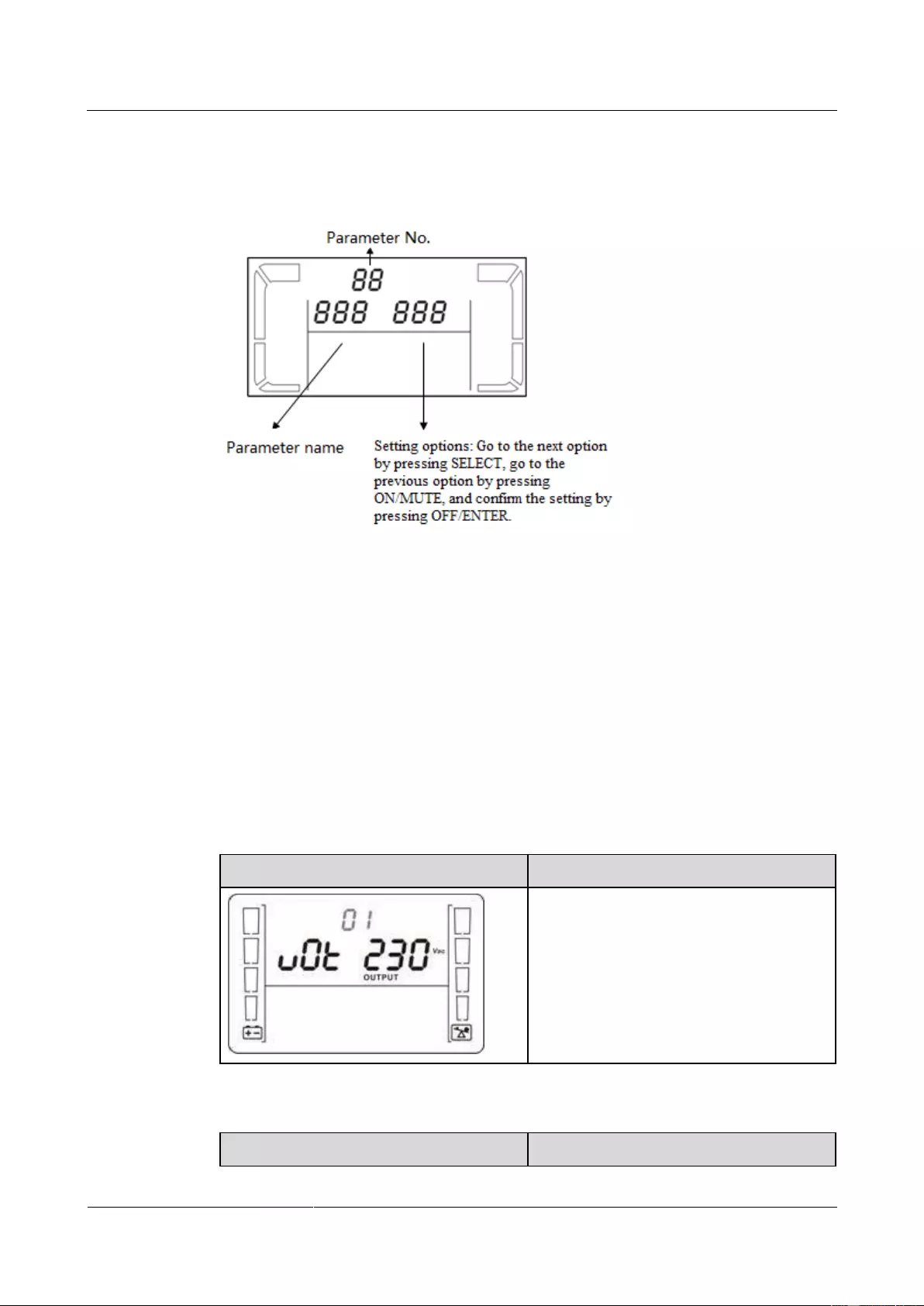
There are seventeen configurable parameters on the LCD. The following figures show the
parameter setting screens.
Figure 4-3 Setting parameters on the LCD
When the UPS is in standby mode or bypass mode, hold down SELECT for 5 seconds to start
setting UPS parameters.
When the UPS is in normal mode or battery mode, hold down SELECT for 5 seconds to
enable or disable the buzzer off (BUZ) function, set the DHCP (DHP) function, or view the IP
address (IP), subnet mask (SUB), and gateway (GAT).
During the setting of UPS parameters, press ON/MUTE for more than 3 seconds. Release the
button when you hear a beep sound to select the previous option. During the setting of UPS
parameters, press SELECT for more than 3 seconds. Release the button when you hear a
beep sound to select the next option. Press OFF/ENTER for more than 3 seconds to confirm
the setting.
The following figures show the seventeen parameter setting screens.
Set the output voltage.
The output voltage can be set as follows:
200: The output voltage is 200 V AC.
208: The output voltage is 208 V AC.
220: The output voltage is 220 V AC.
230: The output voltage is 230 V AC
(default value).
240: The output voltage is 240 V AC.
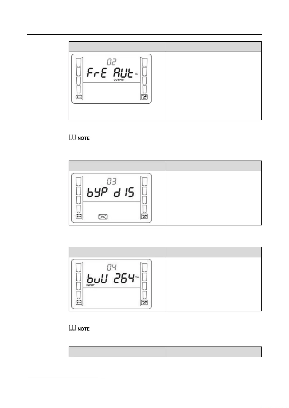
Enable or disable the frequency conversion mode.
UPS2000-G-(1 kVA-3 kVA)
User Manual
Copyright © Huawei Technologies Co., Ltd.
Enable or disable the frequency conversion
mode.
50: The output frequency is always 50 Hz,
and the frequency conversion mode is
enabled.
60: The output frequency is always 60 Hz,
and the frequency conversion mode is
enabled.
AUT: The frequency conversion mode is
disabled (default value).
The CF frequency conversion mode takes priority over the ECO mode. If the CF frequency conversion
mode is enabled, the ECO mode cannot be enabled.
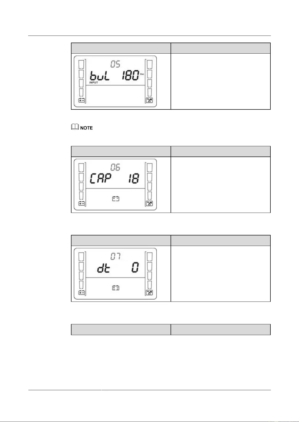
Enable or disable the bypass mode.
Enable or disable the bypass function.
ENA: Enables the bypass mode.
DIS: Disables the bypass mode (default
value).
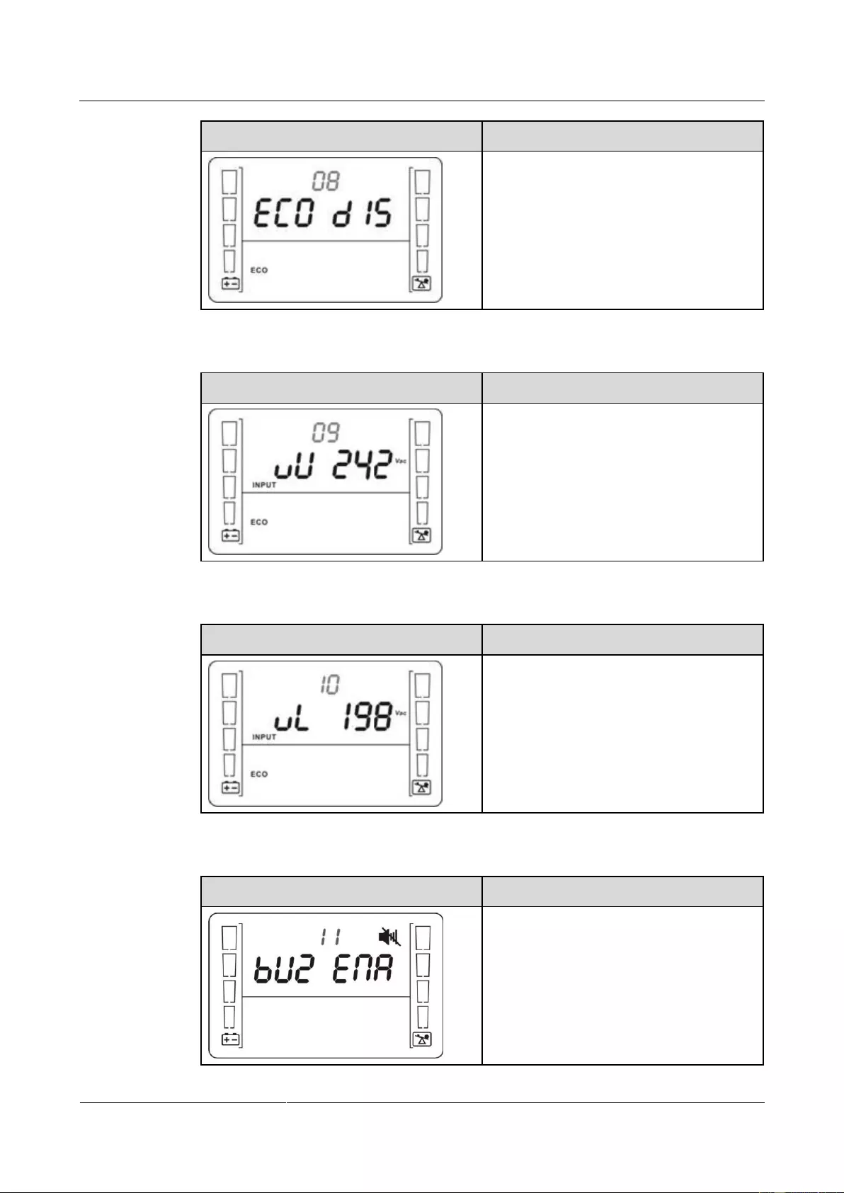
Set the highest input voltage in bypass mode.
Press ▼ or ▲ to adjust and set the highest
input voltage in bypass mode.
230–264: The value range is 230 V AC to
264 V AC, and the default value is 264 V
AC.
The highest input voltage in bypass mode should be higher than the highest input voltage in ECO mode.
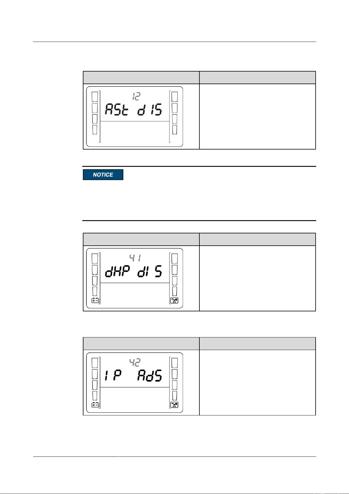
Set the lowest input voltage in bypass mode.
UPS2000-G-(1 kVA-3 kVA)
User Manual
Copyright © Huawei Technologies Co., Ltd.
Press ▼ or ▲ to adjust and set the lowest
input voltage in bypass mode.
170–220: The value range is 170 V AC to
220 V AC, and the default value is 170 V
AC.
The lowest input voltage in bypass mode should be lower than the lowest input voltage in ECO mode.
Set the battery capacity.
Press ▼ or ▲ to adjust and set the UPS
battery capacity.
18–999: Set the UPS battery capacity in the
range of 18 Ah to 999 Ah. (The default
value for standard model is 9 Ah and not
configurable. The default value for long
backup time model is 18 Ah.)
Set the discharge time limit.
Set the backup time limit.
0–999: Set the battery backup time in
battery mode. The value ranges from 0
minutes to 999 minutes.
0: The backup time limit is canceled
(default value).
Enable or disable the ECO mode.
UPS2000-G-(1 kVA-3 kVA)
User Manual
Copyright © Huawei Technologies Co., Ltd.
Enable or disable the ECO function.
ENA: Enables the ECO mode.
DIS: Disables the ECO mode (default
value).
Set the highest allowable voltage in ECO mode.
Press ▼ or ▲ to adjust and set the highest
input voltage in ECO mode.
13–24: Set the parameter based on the
preset output voltage. The value range is
+13 V AC to +24 V AC. (The default value
is +22 V AC.)
Set the lowest allowable voltage in ECO mode.
Press ▼ or ▲ to adjust and set the lowest
input voltage in ECO mode.
13–24: Set the parameter based on the
preset output voltage. The value range is
–13 V AC to –24 V AC. (The default value
is –22 V AC.)
Set the buzzer off function.
Enable or disable the buzzer off function.
ENA: used to enable the buzzer off
function.
DIS: used to disable the buzzer off function.
By default, the buzzer off function is
disabled.
UPS2000-G-(1 kVA-3 kVA)
User Manual
Copyright © Huawei Technologies Co., Ltd.
Set the automatic startup function.
Enable or disable the automatic startup
function.
ENA: Enables the automatic startup
function.
DIS: Disables the automatic startup function
(default value).
The DHCP function setting, IP address display, subnet mask display, and gateway display are
available only when an SNMP card is configured. If no SNMP card is connected, default
values are displayed for the IP address, subnet mask, and gateway. If an SNMP card is
connected, the IP address, subnet mask, and gateway need to be set on the WebUI of the
SNMP card.
DHCP function setting
Address allocation mode setting:
ENA: enabled
DIS: disabled (default value)
IP address display
UPS IP address: can only be displayed but
not configurable. Press ▲ or ▼ to switch
between different screens. On the ESC
screen, press OFF/ENTER to exit. (The
default value is 192.168.0.10.)
Subnet mask display
UPS2000-G-(1 kVA-3 kVA)
User Manual
Copyright © Huawei Technologies Co., Ltd.
Subnet mask: can only be displayed but not
configurable. Press ▲ or ▼ to switch
between different screens. On the ESC
screen, press OFF/ENTER to exit. (The
default value is 255.255.255.0.)
Gateway display
Gateway: can only be displayed but not
configurable. Press ▲ or ▼ to switch
between different screens. On the ESC
screen, press OFF/ENTER to exit. (The
default value is 192.168.0.1.)
No battery alarm disabled setting
No battery alarm disabled setting:
ENA: Disables the function for reporting
the no battery alarm.
DIS: Enables the function for reporting the
no battery alarm (default value).
Exit setting
Exit from the parameter settings screen.
UPS2000-G-(1 kVA-3 kVA)
User Manual
Copyright © Huawei Technologies Co., Ltd.
4.6 Operating Modes
Table 4-5 Operating mode description
When the input voltage is in the
acceptable range, the UPS works
in normal mode, supplies stable
sine wave AC output current,
while charging batteries.
When the input voltage is in the
preset range, the UPS transfers to
bypass mode to save energy.
Frequency conversion
mode
When the input frequency is in the
acceptable range, the UPS sets the
output frequency to 50 Hz or 60
Hz and, while charging batteries.
When the input voltage is
abnormal or an outage occurs, the
UPS transfers to battery mode.
The buzzer beeps once every 4
seconds. The UPS uses batteries to
supply power.
When the UPS works in online
mode and is overloaded, it will
enter the bypass mode if the input
voltage is in an acceptable range.
If the UPS is set to be enables the
bypass mode, the UPS
automatically transfers to bypass
mode after connecting to the
mains.
When the UPS works in bypass
mode, the buzzer beeps once every
10 seconds.
UPS2000-G-(1 kVA-3 kVA)
User Manual
Copyright © Huawei Technologies Co., Ltd.
When the UPS connects to the
mains but is not started in normal
mode or not enables the bypass
mode, the UPS works in standby
mode, in which it only charges
batteries but does not deliver
output.
4.7 Alarm Handing
When an alarm that can be manually cleared exists, hold down OFF/ENTER for over 2 seconds to
manually clear the alarm.
Table 4-6 Alarms
This alarm is
automatically
cleared.
The bypass
voltage is
outside the
scope.
The UPS
remains in
the current
state. If the
UPS works
in bypass
mode, it
transfers to
standby
mode and
has no
output.
Possible cause:
The bypass input
voltage is
abnormal.
Measure: Check
whether the
bypass input
voltage exceeds
the configured
range. If yes,
change the range
or wait until the
bypass input
recovers.
Bypass
frequenc
y
abnorma
l
This alarm is
automatically
cleared.
The bypass
frequency is
outside the
bypass
frequency
range.
The UPS
remains in
the current
state. If the
UPS works
in bypass
mode, it
transfers to
standby
mode and
has no
output.
Possible cause:
The bypass input
frequency is
abnormal.
Measure: Check
whether the
bypass input
frequency exceeds
the configured
range. If yes,
change the range
or wait until the
bypass input

UPS2000-G-(1 kVA-3 kVA)
User Manual
Copyright © Huawei Technologies Co., Ltd.
This alarm
must be
manually
cleared.
The inverter
output
voltage is
not within
±2 V of the
rated output.
If this alarm
is generated
during the
running of
the UPS,
the UPS
transfers to
bypass
mode.
Possible cause:
The bypass
loading
capacity
exceeds the
rated load of
the inverter.
Measure:
Reduce the
output load,
manually clear
the alarm, and
restart the
UPS.
Possible cause:
An internal
fault has
occurred.
Measure:
Contact the
dealer or
Huawei
technical
support.
This alarm is
automatically
cleared.
Discharge
ends for the
UPS in
battery
mode, or the
battery
voltage is
lower than
the
minimum
startup
voltage
(11.28 V) for
the UPS in
normal
mode.
Possible cause:
The battery
voltage is low or
the batteries are
damaged after
EOD.
Measure: Wait for
the batteries to
recover or contact
the battery
supplier to replace
the batteries.
This alarm is
automatically
cleared.
Batteries are
not
connected,
connected
improperly,
or damaged.
The power
supply from
the UPS is
not
affected.
Possible cause:
No batteries
are connected.
Measure:
Connect
batteries.
UPS2000-G-(1 kVA-3 kVA)
User Manual
Copyright © Huawei Technologies Co., Ltd.
Possible cause:
The batteries
are in poor
contact.
Measure:
Check the
battery cable
connection. If
battery cables
are loose,
connect them
securely.
This alarm
must be
manually
cleared.
The voltage
of each
battery
exceeds 15
V (when the
UPS is
started).
This alarm
is generated
because
there are
more
batteries
than
required.
The impact
is as
follows:
If
batteries
are
connecte
d before
the
startup,
the UPS
fails to
start.
If
batteries
are
connecte
d during
the
running
of the
UPS, the
UPS
transfers
to
bypass
mode.
Possible cause:
The actual
number of
batteries does
not meet
requirements.
Measure:
Check that the
actual number
of batteries
meets
requirements.
Possible cause:
The charger is
abnormal.
Measure:
Check that the
charger
voltage is
normal
immediately
after the
batteries are
disconnected.
This alarm is
automatically

UPS2000-G-(1 kVA-3 kVA)
User Manual
Copyright © Huawei Technologies Co., Ltd.
cleared after
the UPS
transfers to
battery mode.
ly transfers
to battery
mode.
When the
battery
undervoltag
e alarm is
generated,
the UPS
automatical
ly transfers
to normal
mode and
starts the
charger for
charging.
This alarm
must be
manually
cleared.
The voltage
of each
battery is
lower than 5
V (when the
UPS is
started).
This alarm
is generated
because
there are
more
batteries
than
required.
The impact
is as
follows:
If
batteries
are
connecte
d before
the
startup,
the UPS
fails to
start.
If
batteries
are
connecte
d during
the
running
of the
UPS, the
UPS
transfers
to
bypass
Possible cause:
The actual
number of
batteries does
not meet
requirements.
Measure:
Check that the
actual number
of batteries
meets
requirements.
Possible cause:
The mains is
abnormal, and
the batteries
are
overdischarged
.
Measure:
Connect to the
mains in
non-battery
test state.

UPS2000-G-(1 kVA-3 kVA)
User Manual
Copyright © Huawei Technologies Co., Ltd.
This alarm is
automatically
cleared.
For standard
model, the
voltage of
each battery
is lower than
11.28 V. For
long backup
time model,
the voltage
of each
battery is
lower than
10.9 V.
The power
supply from
the UPS is
not
affected.
Battery
requirin
g
mainten
ance
This alarm is
automatically
cleared.
The battery
voltage is
lower than
the battery
replacement
voltage (11
V) when
batteries are
in self-check
mode.
The power
supply from
the UPS is
not
affected.
Possible cause:
The actual
number of
batteries does
not meet
requirements.
Measure:
Check that the
actual number
of batteries
meets
requirements.
Possible cause:
The battery is
damaged.
Measure:
Contact the
dealer or
Huawei
technical
support to
replace
batteries.
This alarm is
automatically
cleared.
The voltage
of each
battery is
lower than 5
V, or is
higher than
15 V (when
the UPS is
not started).
The UPS
remains in
the current
state and
cannot start.
This alarm is
automatically
cleared.
The ambient
temperature
exceeds
50ºC.
The UPS
remains in
the current
state and
cannot start.
Possible cause:
The ambient
temperature
exceeds 50ºC
when the UPS is
in standby mode.
As a result, the
UPS cannot start.
Measure: Lower
the ambient
temperature at

UPS2000-G-(1 kVA-3 kVA)
User Manual
Copyright © Huawei Technologies Co., Ltd.
This alarm
must be
manually
cleared.
The bus
voltage is
lower than
320 V.
This alarm
is generated
during the
startup of
the UPS. If
this alarm is
generated,
the UPS
fails to
start.
Possible cause:
The soft-start
resistor is
damaged.
Measure: Contact
the dealer or
Huawei technical
support for repair.
This alarm
must be
manually
cleared.
The bus
voltage is
higher than
450 V.
If this alarm
is generated
during the
running of
the UPS,
the UPS
transfers to
bypass
mode.
Possible cause:
The mains has
experienced a
transient high
voltage.
Measure:
Rectify the
fault and
restart the
UPS.
Possible cause:
The output
supplies power
to special
loads such as
the inductive
and
rectification
loads.
Measure:
Check that the
load types are
supported by
the UPS.
Possible cause:
The hardware
is damaged.
Measure:
Contact the
dealer or
Huawei
technical
support.
This alarm
must be
manually
The bus
voltage is
lower than
If this alarm
is generated
during the
Possible cause:
The hardware

UPS2000-G-(1 kVA-3 kVA)
User Manual
Copyright © Huawei Technologies Co., Ltd.
running of
the UPS,
the UPS
transfers to
bypass
mode.
is damaged.
Measure:
Contact the
dealer or
technical
support.
Possible cause:
An overload
occurred when
the input
voltage was
low.
Measure:
Rectify the
fault and
restart the
UPS.
This alarm is
automatically
cleared.
An error
occurs in the
EEPROM.
All UPS
parameters
are restored
to the
factory
settings. If
this alarm is
generated,
the
customer
needs to
replace the
UPS.
Possible cause:
The EEPROM is
faulty.
Measure: Contact
the dealer or
Huawei technical
support.
This alarm
must be
manually
cleared.
The inverter
voltage is
higher than
1.15 times
the rated
output
voltage.
If this alarm
is generated
during the
running of
the UPS,
the UPS
transfers to
bypass
mode.
Possible cause:
The inverter is
faulty.
Measure: Contact
the dealer or
Huawei technical
support.
This alarm
must be
manually
cleared.
The inverter
output
voltage is
lower than
75% of the
rated output
voltage, and
the output
current is
If this alarm
is generated
during the
running of
the UPS,
the UPS
transfers to
bypass
mode.

UPS2000-G-(1 kVA-3 kVA)
User Manual
Copyright © Huawei Technologies Co., Ltd.
lower than
60% of the
rated output
current.
The first three
alarms are
cleared
automatically
in 10 minutes.
Later alarms,
if generated,
must be
cleared
manually.
The inverter
output
voltage is
lower than
100 V.
If this alarm
is generated
during the
running of
the UPS,
the UPS
transfers to
no output.
After 10
minutes, the
UPS
automatical
ly starts the
inverter. If
this alarm
persists, the
UPS then
transfers to
no output
again. After
the UPS
transfers to
no output
three times,
the alarm
needs to be
manually
cleared.
Possible cause:
The output
load types are
not supported
or the load
exceeds the
specifications.
Measure:
Check whether
the load types
are supported
and reduce the
output load.
Then,
manually clear
the alarm and
restart the
UPS.
Possible cause:
The inverter is
faulty.
Measure:
Contact the
dealer or
Huawei
technical
support.
Possible cause:
The output is
short-circuited.
Measure:
Check whether
the output is
short-circuited.
This alarm
must be
manually
cleared.
The
difference
between the
absolute
value of the
positive bus
voltage and
that of the
negative bus
voltage is
If this alarm
is generated
during the
running of
the UPS,
the UPS
transfers to
bypass
mode.
Possible cause:
The hardware
is damaged.
Measure:
Contact the
dealer or
Huawei
technical
support.

UPS2000-G-(1 kVA-3 kVA)
User Manual
Copyright © Huawei Technologies Co., Ltd.
Possible cause:
The UPS
supplies power
to half-wave
loads.
Measure:
Check that the
load types are
supported by
the UPS.
This alarm
must be
manually
cleared.
The ambient
temperature
exceeds
50ºC
The UPS
transfers to
bypass
mode.
When the
temperature
decreases,
the UPS
automatical
ly starts and
clears this
alarm. If
this alarm is
generated
three times
within 3
hours, the
UPS does
not start or
clear the
fault.
Possible cause:
The ambient
temperature
exceeds 50ºC.
Measure:
Lower the
ambient
temperature.
Possible cause:
Air channels
are blocked.
Measure: Keep
the air intake
and exhaust
vents of the
UPS
unblocked.
Possible cause:
The fan is
abnormal.
Measure:
Clean up the
foreign matter
around the fan.
If the alarm
persists,
contact the
dealer or
Huawei
technical
support.
This alarm is
automatically
cleared.
The charger
has no
output.
The power
supply from
the UPS is
not
affected.
Possible cause:
The internal
connection of the
charger is
abnormal.
Measure: Contact
the dealer or

UPS2000-G-(1 kVA-3 kVA)
User Manual
Copyright © Huawei Technologies Co., Ltd.
Huawei technical
support.
This alarm
must be
manually
cleared.
The voltage
of each
battery
decreases to
below 10 V
when the
charger has
no output
and the UPS
inverter is
started.
The UPS
transfers to
bypass
mode.
Possible cause:
The charger
switching
transistor is faulty.
Measure: Contact
the dealer or
Huawei technical
support.
This alarm is
automatically
cleared.
The inverter
output load
is more than
105% of the
rated load.
The power
supply from
the UPS is
not
affected.
Possible cause:
The load exceeds
the rated loading
capacity of the
inverter.
Measure: Lower
the load or replace
the UPS with a
UPS with a larger
capacity.
This alarm is
automatically
cleared.
The bypass
output load
is more than
110% of the
rated load.
The power
supply from
the UPS is
not
affected.
Possible cause:
The load exceeds
the rated loading
capacity of the
bypass.
Measure: Lower
the load or replace
the UPS with a
UPS with a larger
capacity.
This alarm
must be
manually
cleared.
In battery
mode,
this alarm
is
generated
when the
load
exceeds
the rated
load.
In normal
mode,
when the
bypass
For
battery
mode,
the UPS
transfers
to no
output
mode.
If the
UPS
transfers
from
normal
mode to
Possible cause:
The load exceeds
the rated loading
capacity of the
inverter.
Measure: Lower
the load or replace
the UPS with a
UPS with a larger
capacity.

UPS2000-G-(1 kVA-3 kVA)
User Manual
Copyright © Huawei Technologies Co., Ltd.
input is
normal,
this alarm
is
generated
when the
UPS
transfers
to normal
mode
three
times
within 20
minutes
after the
UPS
transfers
from
normal
mode to
bypass
mode.
In normal
mode,
when the
bypass
input is
abnormal
, this
alarm is
generated
when the
UPS
transfers
to no
output
mode.
bypass
mode
three
times
within
20
minutes,
the UPS
is
locked
in
bypass
mode.
For
normal
mode,
the UPS
transfers
to no
output
mode.
This alarm
must be
manually
cleared.
The bypass
overload
exceeds the
time limit.
The UPS
transfers to
no output.
Possible cause:
The load exceeds
the rated load of
the bypass.
Measure: Reduce
the load or replace
the UPS with a
UPS with a larger
capacity.
This alarm is
automatically
cleared.
The UPS
transfers to
bypass
If the
bypass is
abnormal,
Possible cause:
The inverter is
not started.

UPS2000-G-(1 kVA-3 kVA)
User Manual
Copyright © Huawei Technologies Co., Ltd.
Measure:
Check whether
other alarms
are generated.
If other alarms
are generated,
handle these
alarms
according to
the handling
methods. If
other alarms
are not
generated,
manually start
the UPS.
Possible cause:
The load
exceeds the
rated loading
capacity of the
inverter.
Measure:
Reduce the
load or replace
the UPS with a
larger-capacity
UPS.
This alarm is
automatically
cleared.
The UPS
transfers to
battery
mode.
The UPS
may power
off if
batteries are
abnormal.
Possible cause:
The mains
input is
abnormal.
Measure:
Check the
mains input. If
the mains
input is
abnormal, wait
for the mains
to recover.
Possible cause:
The battery
self-check is in
progress.
Measure:
Check whether
the battery
self-check is in
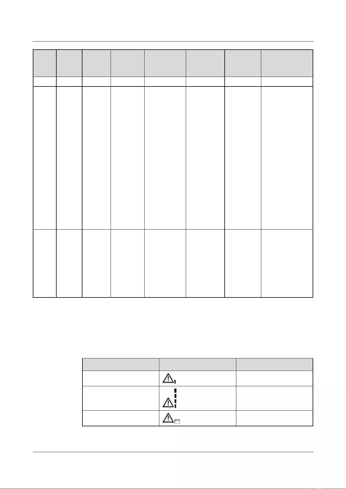
UPS2000-G-(1 kVA-3 kVA)
User Manual
Copyright © Huawei Technologies Co., Ltd.
This alarm is
automatically
cleared.
The
inverter
is not
started.
The load
power
exceeds
the rated
inverter
loading
capability
.
The
temperatu
re
exceeds
the rated
temperatu
re.
If the
bypass is
abnormal,
the UPS
may power
off.
Check whether
other alarms
are generated.
If other alarms
are generated,
clear them.
If there are no
other alarms,
start the
inverter
manually.
This alarm is
automatically
cleared.
The mains
input is
abnormal.
When the
UPS works
in battery
mode, the
UPS may
power off if
the batteries
are
abnormal.
Check the mains
input. If the mains
input is abnormal,
wait until the
mains input
recovers.
4.8 Alarm Indication
Table 4-7 Alarm indication
Insufficient battery capacity
Beeps twice every second.

UPS2000-G-(1 kVA-3 kVA)
User Manual
Copyright © Huawei Technologies Co., Ltd.

UPS2000-G-(1 kVA-3 kVA)
User Manual
Copyright © Huawei Technologies Co., Ltd.
5 Operations
5.1 Checking Before Powering On the UPS
AC power cable colors comply with local electrical regulations.
No short circuits occur in inputs and outputs.
Cables are securely connected.
Battery cables are correctly connected to battery terminals. The battery voltage meets the
requirements.
Cables are properly connected between the UPS and batteries.
Power cables and signal cables are correctly identified.
Cables are neatly routed and securely bound.
Devices are installed and cables are routed in ways that facilitate modification, capacity
expansion, and maintenance.
The UPS is properly grounded.
The voltage between the neutral wire and the ground cable is less than 5 V AC.
The input voltage rang for the mains to start the UPS is 120–280 V AC (or 80–280 V AC
after the UPS powers on). The battery voltage range is (Number of batteries x 10.  to
to
(Number of batteries x 14) V DC.
5.2 Starting the UPS
UPS2000-G-(1 kVA-3 kVA)
User Manual
Copyright © Huawei Technologies Co., Ltd.
In the preset mode, LCD will return to the main page with 10 seconds of no operation.
If the long backup time model is not connected to an external battery pack, the buzzer
keeps buzzing.
Charge the batteries used for the first time for 5 hours. Otherwise, the battery discharge
time will decrease.
The UPS performs a battery self-check automatically once a week. If batteries are faulty,
an alarm is generated.
If the UPS is connected to the mains, when the battery packs or battery strings connect to
the UPS with long backup time for the first time, you must do a battery self-check
manually, in order to confirm the battery connection is normal. The method is: hold down
the ON/MUTE button on the front panel for 5 seconds, then the UPS transfer to battery
mode to do a shallow discharge test, after 10 seconds it automatically back to line mode.
The UPS with long backup time provides a charge current of 4 A and the current is not
configurable. If the UPS needs to connect to battery packs or battery strings, the total
battery capacity must exceed 18 Ah. Otherwise, batteries may be damaged. If the capacity
of external battery packs or battery strings to be connected exceeds 40 Ah, it is
recommended that an external charger be purchased to increase the charge current. If an
external charger is not purchased, the charge time will be long.
The 1 kVA UPS with standard backup time has two built-in batteries, the 2 kVA UPS with
standard backup time have four built-in batteries, the 3 kVA UPS with standard backup
time have six built-in batteries. If the 1 kVA UPS with long backup time needs to connect
to external battery strings, each battery string must consist of three 12 V batteries
connected in series. If the 2 kVA UPS with long backup time needs to connect to external
battery strings, each battery string must consist of six 12 V batteries connected in series. If
the 3 kVA UPS with long backup time needs to connect to external battery strings, each
battery string must consist of eight 12 V batteries connected in series.
For the UPS with standard backup time, the battery capacity has a fixed value of 9 Ah and
the charge current has a fixed value of 1 A. Set the battery capacity to the total capacity of
all batteries actually connected. Set the battery capacity for the long backup time model
based on site requirements. The default value is 18 Ah. For example, if eight batteries (9
Ah, 12 V) are connected in series to form a battery string, and two of such battery strings
are connected in parallel and then to the 3 kVA long backup time model, set battery
capacity to 18 Ah (9 Ah + 9 Ah). This parameter affects the backup time calculation.
Incorrect setting will cause incorrect display of the backup time on the LCD.
During the setting of UPS parameters, press ON/MUTE for more than 3 seconds. Release the button
when you hear a beep sound to select the previous option. During the setting of UPS parameters, press
SELECT for more than 3 seconds. Release the button when you hear a beep sound to select the next
option. During the setting of UPS parameters, press OFF/ENTER for more than 3 seconds to confirm
the setting.
Procedure: 1. After power on the UPS, it enters standby mode, as shown in Figure 5-1. Hold down the
SELECT button for 5 seconds. The UPS enters the preset mode.
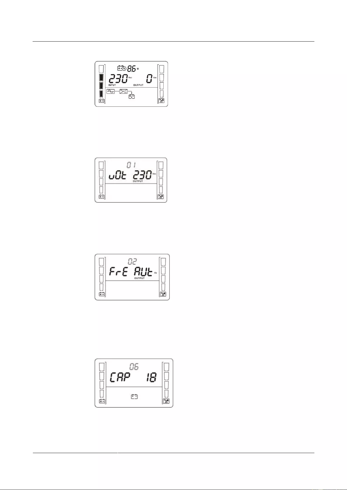
UPS2000-G-(1 kVA-3 kVA)
User Manual
Copyright © Huawei Technologies Co., Ltd.
Figure 5-1 Power—on and standby screen
2. Set the voltage level based on the actual output voltage. The voltage level can be set to
200 V, 208 V, 220 V, 230 V (default), or 240 V.
Figure 5-2 Setting the output voltage
3. Set the system output frequency based on the rated frequency. The values include 50 Hz,
60 Hz, and AUT (default).
Figure 5-3 Setting the system output frequency
4. (This step is required only for the UPS with long backup time.) Set the battery capacity
to the total capacity of all batteries actually connected. The default value is 18 Ah for the
UPS with long backup time, and the value can range from 18 Ah to 999 Ah.
Figure 5-4 Setting the battery capacity
5. Start the UPS to inverter mode.
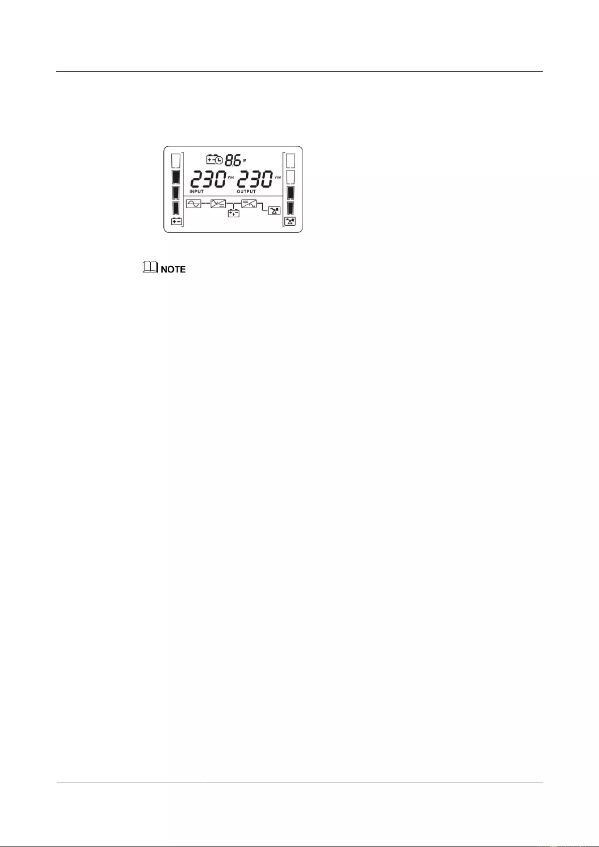
UPS2000-G-(1 kVA-3 kVA)
User Manual
Copyright © Huawei Technologies Co., Ltd.
Hold down the ON/MUTE button on the front panel for over 5 seconds to make the UPS
transfer to inverter mode output. The default value is 230 V.
Figure 5-5 LCD display after the UPS starts to inverter mode
To prevent triggering overload protection, start the loads with higher power and then loads with lower
power.
5.3 Shutting Down the UPS
Normal Mode
If the UPS is originally in normal mode, hold down OFF/ENTER for over 2 seconds will
enable the UPS to enter the standby mode or bypass mode (if set or enabled before).
Battery Mode
Hold down OFF/ENTER for over 2 seconds to turn off the UPS in battery mode.
5.4 Transferring to Bypass Mode
When the input power supply is normal and the UPS is started in normal mode, hold down
ON/MUTE and SELECT both for 5 seconds to enable the UPS enter the bypass mode. If the
input voltage exceeds the acceptable range, the UPS will not enter the bypass mode.
5.5 Transferring from Bypass Mode to Normal Mode
When the UPS is in bypass mode, hold down ON/MUTE and SELECT both for 5 seconds to
enable the UPS enter the invert mode.
5.6 Transferring to Battery Self-check
In normal mode, ECO mode, or frequency conversion mode, hold down ON/MUTE for more
than 5 seconds to enter the battery self-check test.

UPS2000-G-(1 kVA-3 kVA)
User Manual
Copyright © Huawei Technologies Co., Ltd.
5.7 Enabling or Disabling the Buzzer
LCD control:
When the UPS is in standby mode or bypass mode, hold down SELECT for 5 seconds
to start setting UPS parameters. The parameter 11 can enable or disable the buzzer off
function. If you enable the buzzer off function on the LCD, you need to disable this
function on the LCD if alarm sound is required. Otherwise, if a new alarm is generated,
there is no alarm sound. If the UPS is shut down and powered on again, the buzzer
restores to the on status.
When the UPS is in normal mode or battery mode, hold down SELECT for 5 seconds to
start setting only for parameter 11 to enable or disable the buzzer off function.
During the setting of UPS parameters, press ON/MUTE for more than 3 seconds. Release the button
when you hear a beep sound to select the previous option. During the setting of UPS parameters, press
SELECT for more than 3 seconds. Release the button when you hear a beep sound to select the next
option. Press OFF/ENTER for more than 3 seconds to confirm the setting.
Button control:
Hold down ON/MUTE for 2–5 seconds when the UPS is in battery mode to enable or
disable the buzzer. However, when the UPS sends a new alarm, the mute function is
unavailable, you need to disable the buzzer again.
5.8 Manually Clearing Alarms
When an alarm that can be manually cleared exists, hold down OFF/ENTER for over 2
seconds to manually clear the alarm.
5.9 Entering Alarm Cause ID Screen
Hold down SELECT and OFF/ENTER both for 5 seconds to enter the alarm cause ID screen.
Press ON/MUTE to view the previous option. Press SELECT to view the next option.
UPS2000-G-(1 kVA-3 kVA)
User Manual
6 Maintenance and Storage
Copyright © Huawei Technologies Co., Ltd.
6 Maintenance and Storage
6.1 Maintenance
The UPS must be maintained or replaced by professionals. Common users are not allowed to
perform such a task. If the UPS need to be replaced, contact the dealer.
Hand over used batteries to recyclers or pack them with the package for new batteries and send them to
the dealer.
6.2 Storage
Before storing the UPS, charge it for 5 hours. The correct way of storing the UPS is standing
the UPS without unpacking in a dry place. During the storage period, maintain the UPS by
charging its batteries as follows:
Table 6-1 UPS charging during storage
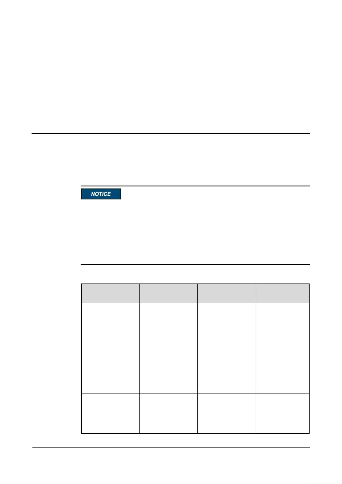
UPS2000-G-(1 kVA-3 kVA)
User Manual
Copyright © Huawei Technologies Co., Ltd.
7 Routine Maintenance
7.1 UPS Maintenance
Only trained personnel are allowed to perform maintenance. Before performing operations
on a device, wear electrostatic discharge (ESD) clothes, ESD gloves, and an ESD wrist
strap. Do not wear jewelry or watches during the operation to avoid electric shocks or
burns.
Use insulated tools when maintaining internal devices. Only trained personnel are allowed
to perform maintenance.
Maintain UPSs regularly based on the following requirements. Otherwise, the UPSs may
fail to operate properly and the lifespan may be shortened.
Table 7-1 Routine maintenance items for UPSs
Ambient
temperature:
0–40°C
Humidity: 0–95%
RH
(non-condensing)
If the humidity
and temperature
are abnormal,
check the air
conditioner
status.
If the input
voltage is
abnormal, check
the power grid
status and input
cable connection.
Check that all units
are operating
properly by
observing the status
icons on the LCD,
If an alarm is
present, rectify the
fault by checking the
device status and
parameters.
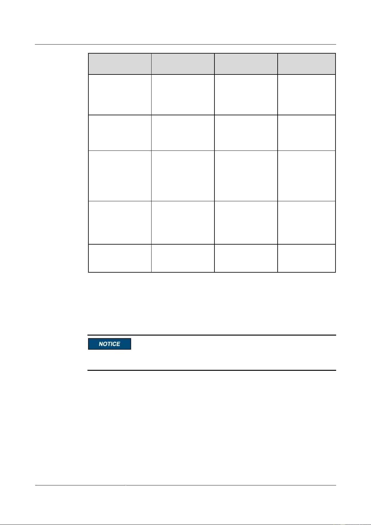
UPS2000-G-(1 kVA-3 kVA)
User Manual
Copyright © Huawei Technologies Co., Ltd.
and no fault or alarm
information is
displayed in active
alarm or historical
alarms.
Wipe the cabinet
surface using a white
paper and the paper
does not turn black.
Clean the dust,
especially in the
front panel.
Check the output
voltage level and
frequency, the
number of batteries
and the actual battery
capacity.
Power cables and
terminals (between
the UPS and external
power distribution
equipment)
The insulation layers
of cables are intact
and terminals are
free from noticeable
sparks.
Replace the
cables.
Secure the output
terminals.
No battery alarm is
generated.
If an alarm is
present, rectify the
fault.
7.2 Battery Maintenance
Before installing batteries, read through the battery user manuals and pay attention to safety
precautions and connection methods provided by battery manufacture.
When installing and maintaining batteries, pay attention to the following points:
Wrap tools with insulation tape to prevent electric shock.
Protect your eyes with relevant devices and apply other protective measures.
Wear rubber gloves and a protective coat in case of electrolyte overflow.
When moving batteries, avoid handling the battery upside down, handle batteries gently,
and pay attention to personal safety.
Keep the battery switch off when installing or maintaining the batteries.
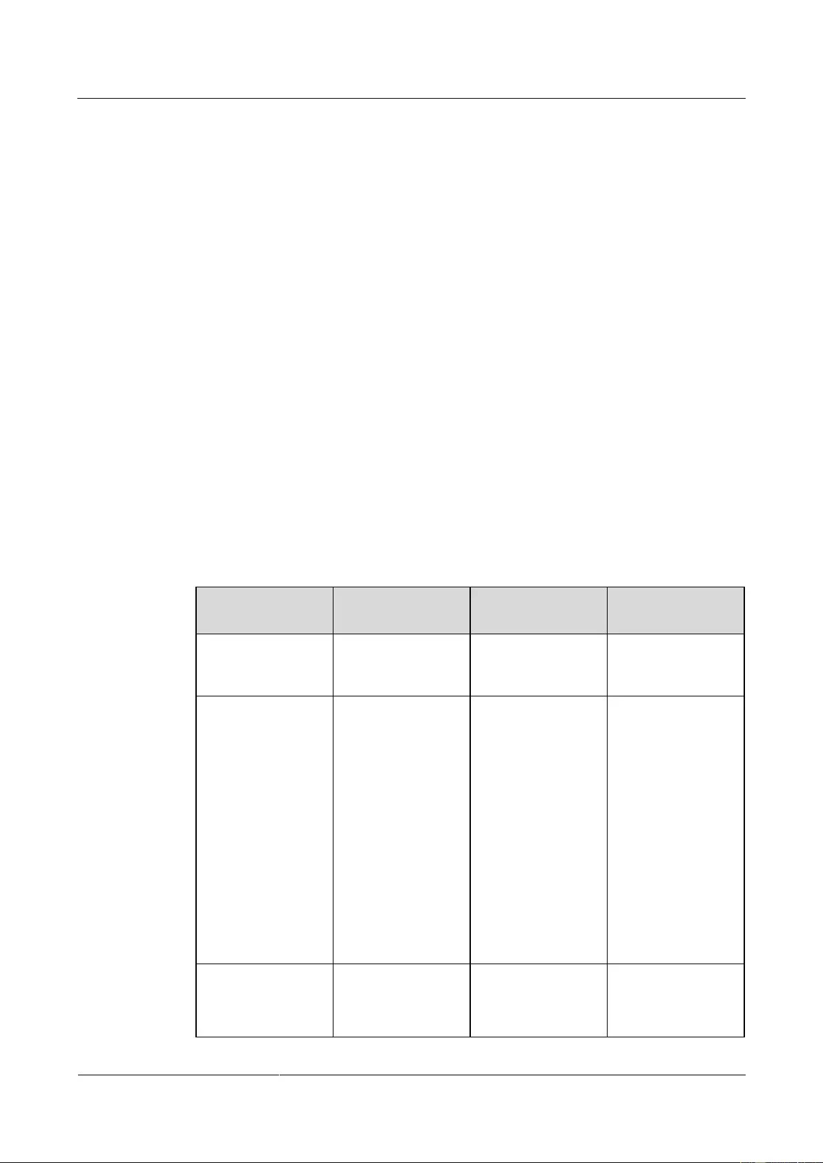
UPS2000-G-(1 kVA-3 kVA)
User Manual
Copyright © Huawei Technologies Co., Ltd.
Precautions
Before battery maintenance, get the tools, such as handles, insulated. Do not place metal
tools on exposed battery terminals.
Never use any organic solvent to clean batteries.
Never try to remove the safety valve or fill anything into batteries.
Never smoke or use fire around batteries.
After battery discharge, charge batteries to ensure a required battery capacity.
Only professionals are allowed to perform maintenance tasks.
If batteries have not been discharged for a long time, discharge and charge them in
equalized mode at least once every three months to activate them. Each charge should
last at least 4 hours.
Normally, discharge and charge batteries once every four to six months. Each charge
should last at least 4 hours.
In high-temperature areas, discharge and charge batteries once every two months. Each
charge should last at least 4 hours.
Do not overdischarge batteries. After discharging batteries, fully charge them within 24
hours.
Ensure that the battery discharge duration is 999 minutes at most and 0 minute by default.
If you set the value to 0 minute, the discharge time is not limited.
Routine maintenance items for batteries
Table 7-2 Routine maintenance items for batteries
No battery alarm is
generated.
Identify the cause
based on the alarm
information.
1. The surface is
clean and tidy
without stains.
2. The battery
terminals are
intact.
3. Batteries are free
from damage and
cracks.
4. Batteries are free
from acid
leakage.
5. Batteries are not
deformed or
bulged.
If the battery
appearance is
abnormal, contact
Huawei technical
support.
Battery operating
temperature
1. The ambient
battery
temperature is
25±5°C.
1. Identify the
cause of the
abnormal battery
operating
UPS2000-G-(1 kVA-3 kVA)
User Manual
Copyright © Huawei Technologies Co., Ltd.
2. The battery
operating
temperature is
lower than
battery
temperature +
20°C.
3. Battery charge
and discharge
conditions meet
the requirements
specified in the
battery
specifications.
temperature.
2. If the fault
persists, contact
Huawei technical
support.
Charge voltage of
battery string
Equalized
voltage 14.16 V
x Number of
batteries
(tolerance ±1%)
Float voltage
13.68 V x
Number of
batteries
(tolerance ±1%)
1. If the voltage
drop between the
battery string
output terminals
and the battery
input terminals at
the UPS side is
greater than 1%
of the battery
string voltage,
check whether
the cable
between the
battery string and
the UPS is
excessively long,
or the cable
diameter is
excessively
small.
2. Check whether
the equalized
charging voltage
and float
charging voltage
are correctly set
for the UPS.
3. If the fault
persists, contact
Huawei technical
support.
Battery temperature
sensor measurement
accuracy
The difference
between the
temperature
measured by the
temperature sensor
and the temperature
1. Install the
temperature
sensor in the
correct position.
2. Replace the
battery

UPS2000-G-(1 kVA-3 kVA)
User Manual
Copyright © Huawei Technologies Co., Ltd.
displayed on the
LCD is less than
3°C.
The settings of
battery management
parameters meet the
requirements in the
user manual.
Set parameters
correctly.
Tightness of bolts on
battery terminals
The location of the
signs marked on
battery terminals
indicating tight
connections does not
change.
Take photos from
multiple angles and
contact Huawei
technical support.
No cable
deteriorates and the
insulation layer does
not crack.
Replace the faulty
cable.
Equalized
charging voltage:
14.16 V ± 0.1 V
Float charging
voltage: 13.68 V
± 0.1 V
1. Check whether
the equalized
charging voltage
and float
charging voltage
of a battery are
normal.
2. If the charging
voltage of a
battery exceeds
the specifications
requirement,
perform a
complete forcible
equalized
charging for the
battery, and
check again
whether the
voltage is
normal.
3. If the fault
persists, contact
Huawei technical
support.
Battery connection
reliability
1. Each battery
terminal is
connected
reliably. (When
battery strings
are powered off,
1. Rectify any
abnormal
connection.
2. If the fault
persists, contact
Huawei technical
UPS2000-G-(1 kVA-3 kVA)
User Manual
Copyright © Huawei Technologies Co., Ltd.
check the
reliability of each
terminal in the
order from
positive
terminals to
negative
terminals.)
2. The tightening
torque of each
battery screw
meets the
requirements of
the battery
manufacturer. (A
torque wrench is
used for
checking the
torque. After
checking that the
battery screws
meet the
requirements,
mark the screws
for later check.)
UPS2000-G-(1 kVA-3 kVA)
User Manual
Copyright © Huawei Technologies Co., Ltd.
8 Troubleshooting
When the UPS works abnormally, rectify the fault by referring to the following table.
Table 8-1 Faults and troubleshooting measures
The main power is normal,
but no indicator turns on and
the buzzer generates no
tone.
The mains input power
cable is disconnected.
Check the input power
cable.
The mains input power
cable is incorrectly
connected to the UPS output
end.
Correctly connect the mains
input power cable to the
UPS input terminal.
and blink on the
LCD and the buzzer beeps
once every second.
The external or internal
batteries are incorrectly
connected.
Check that all batteries are
connected correctly.
and blink on the
LCD and the buzzer beeps
twice every second.
Remove surplus load from
the UPS output end.
The UPS is overloaded and
supplying power to devices
in bypass mode.
Remove surplus load from
the UPS output end.
The UPS is overloaded
server times within a short
period of time. The UPS is
locked in bypass mode and
loads are directly connected
to the main power source.
Remove surplus load from
the UPS output end, and
then shut down and restart
the UPS.
The battery backup time is
shorter than the time given
in specifications.
Batteries are not fully
charged.
Charge batteries for at least
5 hours and then check the
battery capacity. If the
battery capacity is still
insufficient, contact the
dealer or Huawei technical
support.

UPS2000-G-(1 kVA-3 kVA)
User Manual
Copyright © Huawei Technologies Co., Ltd.
Huawei technical support to
replace batteries.
UPS2000-G-(1 kVA-3 kVA)
User Manual
Copyright © Huawei Technologies Co., Ltd.
9 Specifications
9.1 Physical Specifications
Table 9-1 Physical specifications
Net dimensions (D mm x
W mm x H mm)
9.2 Environmental Specifications
Table 9-2 Environment specifications
0%–95% RH (non-condensing)
Storage and
transportation
temperature
–40°C to +70°C (battery pack: –20°C to +40°C)
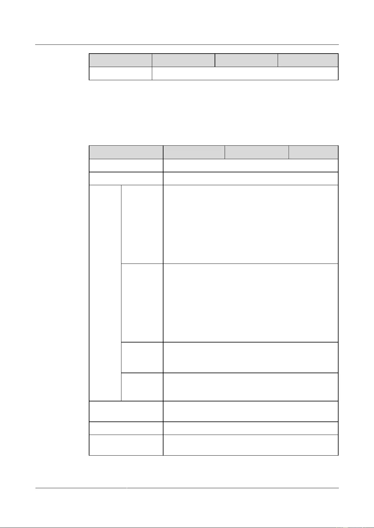
UPS2000-G-(1 kVA-3 kVA)
User Manual
Copyright © Huawei Technologies Co., Ltd.
9.3 Mains Input Electrical Specifications
Table 9-3 Mains input electrical specifications
Single-phase (L/N) input +PE cable
200V AC/208V AC/220V AC/230V AC/240V AC
Lowest
conversion
voltage
When the ambient temperature is 0–35°C:
160/140/120/110 V AC (tolerance ±5%)
(Ratio of actual load to rated load:
100%–80%/80%–70%/70%–60%/60%–0)
When the ambient temperature is 35–40°C:
175/155/135/125 V AC (tolerance ±5%)
(Ratio of actual load to rated load:
100%–80%/80%–70%/70%–60%/60%–0)
When the ambient temperature is 0–35°C:
175/155/135/125 V AC (tolerance ±5%)
(Ratio of actual load to rated load:
100%–80%/80%–70%/70%–60%/60%–0)
When the ambient temperature is 35–40°C:
190/170/150/140 V AC (tolerance ±5%)
(Ratio of actual load to rated load:
100%–80%/80%–70%/70%–60%/60%–0)
Highest
conversion
voltage
300 V AC (tolerance ±5%, load percentage < 80%)
280 V AC (tolerance ±5%, 80% < load percentage < 100%,
after 15 minutes to battery mode)
290 V AC (tolerance ±5%, load percentage < 80%)
270 V AC (tolerance ±5%, 80% < load percentage < 100%)
Input power factor
(100% resistive load)
Diesel generator input
capacity
Minimum 1.5 times the UPS rated capacity
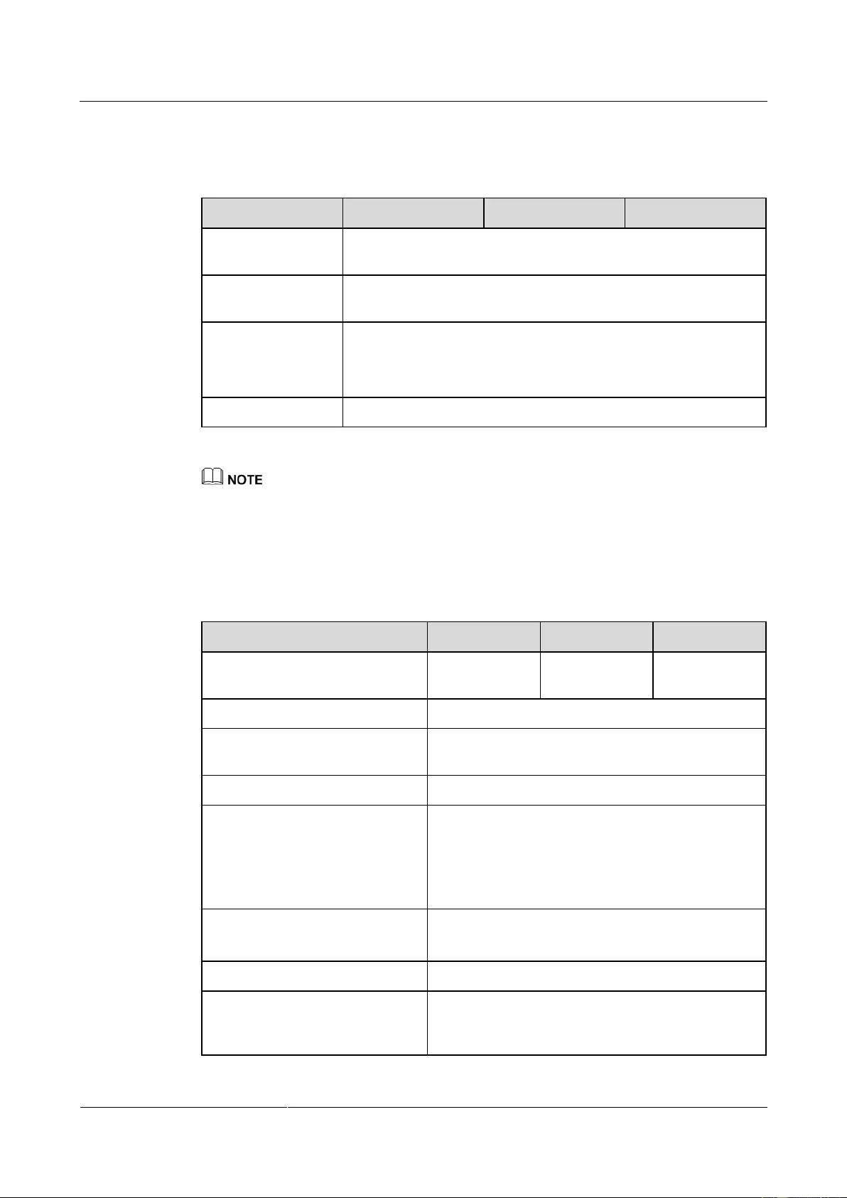
UPS2000-G-(1 kVA-3 kVA)
User Manual
Copyright © Huawei Technologies Co., Ltd.
9.4 Bypass Input Electrical Specifications
Table 9-4 Bypass Input Electrical Specifications
Bypass frequency
tolerance
Bypass overload
capability
110%–120%, 30 minutes
120%–130%, 10 minutes
130%–150%, 1 minute
The upper and lower thresholds of bypass voltage tolerance are configurable on the LCD.
9.5 Output Electrical Specifications
Table 9-5 Output electrical specifications
200 V AC/208 V AC/220 V AC/230 V AC/240 V
AC
In normal mode, the UPS output frequency is
consistent with the input frequency, which is 50
Hz or 60 Hz with the tolerance of ±3 Hz.
In battery mode, the frequency is 50 Hz or 60 Hz
(tolerance ±0.05%).
Total distortion of output voltage
waveform (THDv)
< 6% (non-resistive load)
< 3% (resistive load)
Inverter overload capability
When the ambient temperature is 0–35°C:
− 105%–110%: The UPS automatically shuts
down (in battery mode) or transfers to bypass
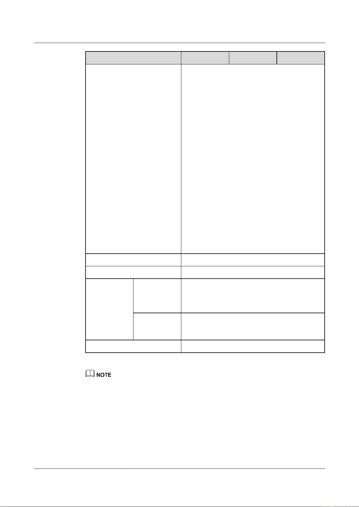
UPS2000-G-(1 kVA-3 kVA)
User Manual
Copyright © Huawei Technologies Co., Ltd.
mode (in line mode) after 10 minutes.
− 110%–130%: The UPS automatically shuts
down (in battery mode) or transfers to bypass
mode (in line mode) after 1 minutes.
− 130%–150%: The UPS automatically shuts
down (in battery mode) or transfers to bypass
mode (in line mode) after 3 seconds.
− > 150%: The UPS automatically shuts down
(in battery mode) or transfers to bypass mode
(in line mode) after 0.5 seconds max.
When the ambient temperature is 35–40°C:
− 105%–110%: The UPS automatically shuts
down (in battery mode) or transfers to bypass
mode (in line mode) after 5 minutes.
− 110%–130%: The UPS automatically shuts
down (in battery mode) or transfers to bypass
mode (in line mode) after 30 seconds.
− 130%–150%: The UPS automatically shuts
down (in battery mode) or transfers to bypass
mode (in line mode) after 1.5 seconds.
− > 150%: The UPS automatically shuts down
(in battery mode) or transfers to bypass mode
(in line mode) after 0.5 seconds max.
Dynamic voltage tolerance ±5%
Average frequency tracking rate
Transferring
from normal
mode to battery
mode
Bypass to ECO
or ECO to
bypass
In frequency conversion mode, the output load is derated to 80% of the rated capacity.
If the output voltage is 200 V AC or 208 V AC, the output load is derated to 80% of the rated
capacity.
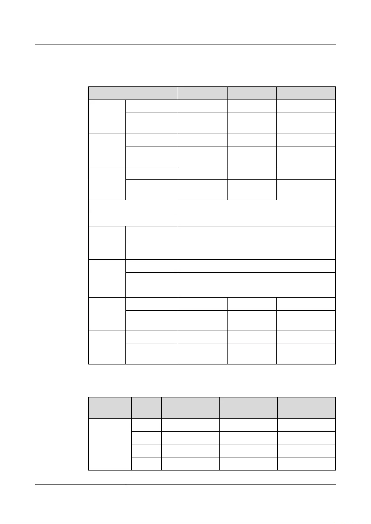
UPS2000-G-(1 kVA-3 kVA)
User Manual
Copyright © Huawei Technologies Co., Ltd.
9.6 Battery Specifications
Table 9-6 Battery specifications
> 4 minutes (at full rated load)
Depending on the capacity of external batteries.
Charger
rated
charge
current
Equalized
charging
voltage
Table 9-7 Power backup specifications of the battery pack
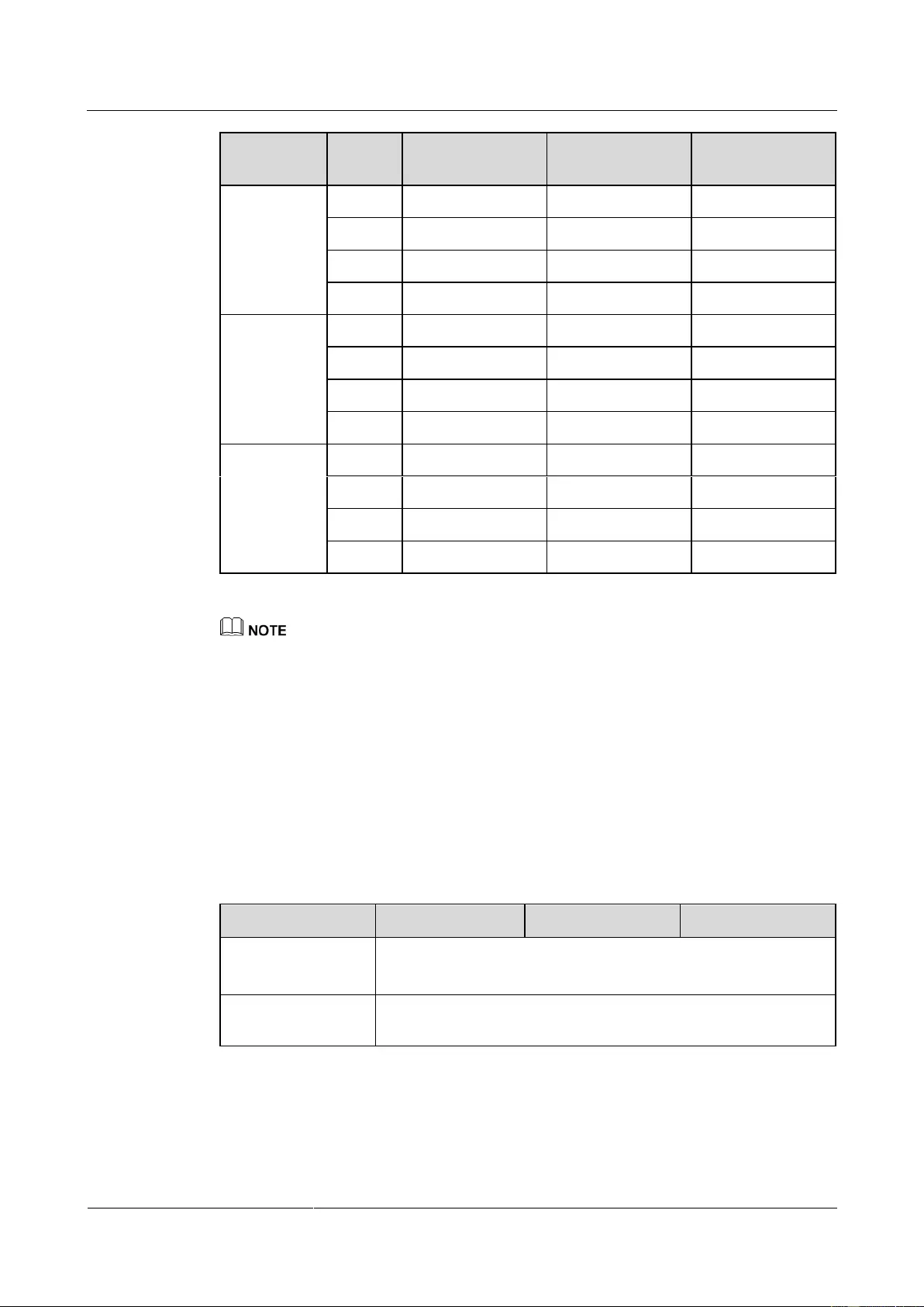
UPS2000-G-(1 kVA-3 kVA)
User Manual
Copyright © Huawei Technologies Co., Ltd.
The battery pack (ESS-36V12-9*2AHBPVBB01) for 1 kVA UPS with long backup time contain two
group battery strings. The battery pack (ESS-72V12-9AHBPVBB01) for 2 kVA UPS with long
backup time only contain one group battery strings. The battery pack (ESS-96V12-9AHBPVBB02)
for 3 kVA UPS with long backup time only contain one group battery strings.
The 1 kVA UPS with long backup time is allowed a maximum of two battery packs
(ESS-36V12-9*2AHBPVBB01) in parallel. The 2 kVA UPS with long backup time is allowed a
maximum of four battery packs (ESS-72V12-9AHBPVBB01) in parallel. The 3 kVA UPS with long
backup time is allowed a maximum of four battery packs (ESS-96V12-9AHBPVBB02) in parallel.
9.7 ECO Feature
Table 9-8 ECO feature
Default value: ±22 V A (configurable on the LCD)
The range is ±(13 V AC-24 V AC)
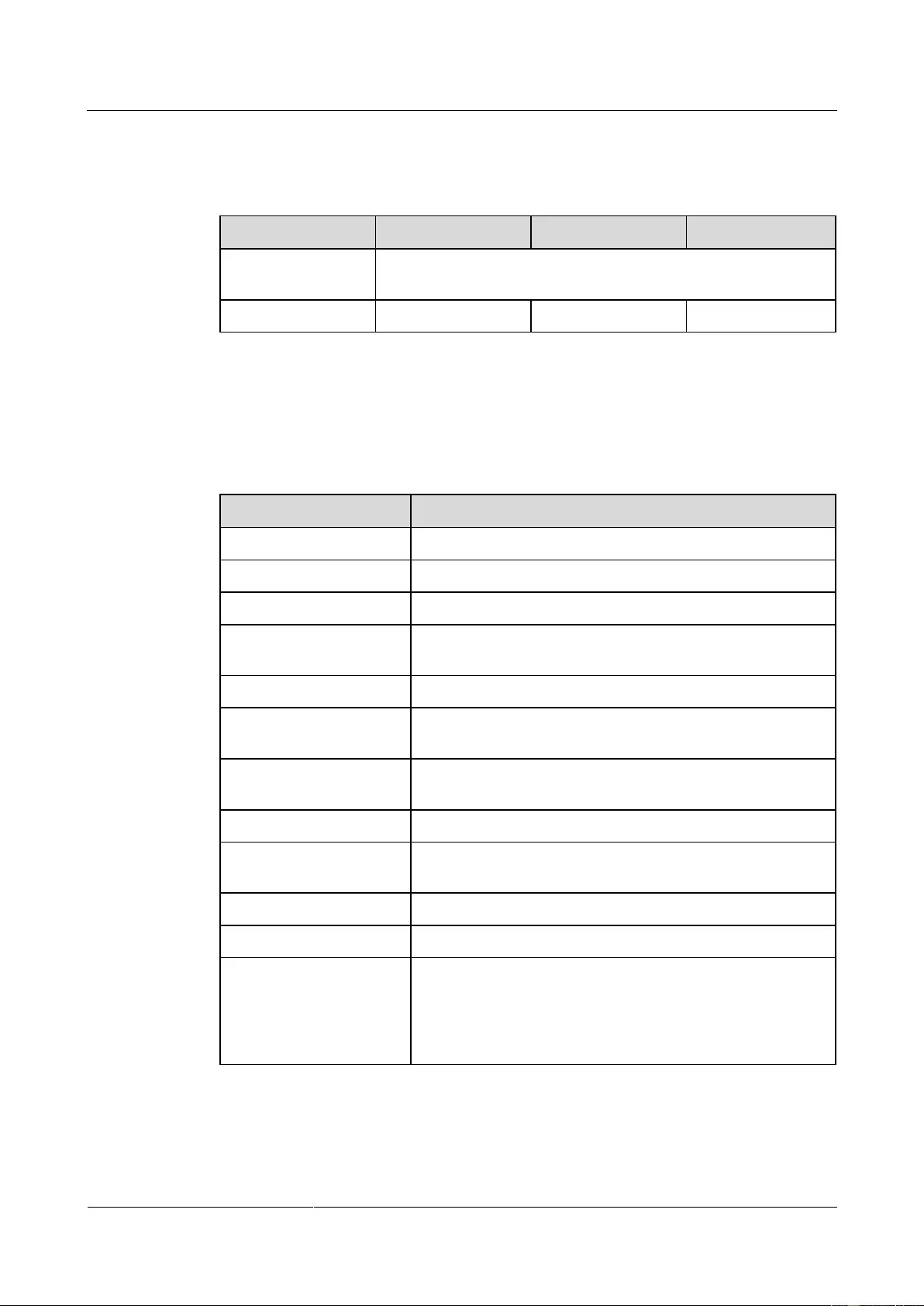
UPS2000-G-(1 kVA-3 kVA)
User Manual
Copyright © Huawei Technologies Co., Ltd.
9.8 System Electrical Specifications
Table 9-9 System Electrical Specifications
Number of UPSs
connected in parallel
9.9 Safety Regulations and EMC
Table 9-10 Safety Regulations and EMC
Anti-electromagnetic
interference
Radiated susceptibility
(RS)
Electrical fast
transient/burst (EFT/B)
Power magnetic
susceptibility (PMS)
IEC61000-3-11 (input current > 16 A)
Impact current (lightning
protection)
IEC/EN60240-2
IEC/EN61000-4-5
YD/T1095-2000
YD/T944-2007

UPS2000-G-(1 kVA-3 kVA)
User Manual
A Acronyms and Abbreviations
Copyright © Huawei Technologies Co., Ltd.
A Acronyms and Abbreviations
Economy Control Operation
Electrically erasable programmable read-only memory
HTTP-Hypertext Transfer Protocol
Simple Network Management Protocol
Total harmonic distortion of output voltage
Uninterruptible power system
UPS2000G(Digital Power|Data Center Facility|UPS|UPS2000|UPS2000G)
Document List
My Support
|
Feedback
| Help
Temporary Software Authorization Application
Note: This is an automatic approval process. After the application is approved, the users have the permission to download the software package of the corresponding product version within seven days.
| Version | |
| Applicant | |
| User |
|
-
Page 1
UPS2000-A-(6 kVA-10 kVA) User Manual Issue Date 2019-12-19 HUAWEI TECHNOLOGIES CO., LTD. -
Page 2
Notice The purchased products, services and features are stipulated by the contract made between Huawei and the customer. All or part of the products, services and features described in this document may not be within the purchase scope or the usage scope. Unless otherwise specified in the contract, all statements, information, and recommendations in this document are provided «AS IS»… -
Page 3: About This Document
Indicates a potentially hazardous situation which, if not avoided, could result in equipment damage, data loss, performance deterioration, or unanticipated results. NOTICE is used to address practices not related to personal injury. Issue 05 (2019-12-19) Copyright © Huawei Technologies Co., Ltd.
-
Page 4
Updated the section «Operating Environment». Issue 03 (2018-01-16) Added the description of device application scenarios. Issue 02 (2017-11-27) Updated the section «Operating Environment». Issue 01 (2015-08-18) This is the first release. Issue 05 (2019-12-19) Copyright © Huawei Technologies Co., Ltd. -
Page 5: Table Of Contents
3.2.3.3 Connecting Cables to the UPS Standard Version with Long Backup Time …………41 3.2.3.4 Connecting Cables to the UPS Professional Version with Long Backup Time ………… 42 3.3 Parallel System Installation ……………………….44 Issue 05 (2019-12-19) Copyright © Huawei Technologies Co., Ltd.
-
Page 6
6 Communications ……………………110 6.1 Optional Communications Components ……………………110 6.2 SNMP Card …………………………..110 6.3 Modbus Card …………………………..111 6.4 Dry Contact Card …………………………111 7 Routine Maintenance ………………….. 112 Issue 05 (2019-12-19) Copyright © Huawei Technologies Co., Ltd. -
Page 7
9.7 ECO Feature …………………………..129 9.8 Parallel Feature …………………………… 130 9.9 Safety Regulations and EMC ………………………. 130 A Parallel Parameter List ………………….132 B Alarm Handling ……………………133 C Acronyms and Abbreviations ………………..153 Issue 05 (2019-12-19) Copyright © Huawei Technologies Co., Ltd. -
Page 8: Safety Information
The «NOTICE», «WARNING», and «DANGER» statements in this document do not cover all the safety instructions. They are only supplements to the safety instructions. Huawei will not be liable for any consequence caused by the violation of general safety requirements or design, production, and usage safety standards.
-
Page 9
Keep irrelevant people away from the equipment. Only operators are allowed to access the equipment. Use insulated tools or tools with insulated handles, as shown in the following figure. Issue 05 (2019-12-19) Copyright © Huawei Technologies Co., Ltd. -
Page 10
To avoid electric shock, do not connect safety extra-low voltage (SELV) circuits to telecommunication network voltage (TNV) circuits. Issue 05 (2019-12-19) Copyright © Huawei Technologies Co., Ltd. -
Page 11: Personnel Requirements
Do not power on the equipment before it is installed or confirmed by professionals. 1.2 Personnel Requirements Personnel who plan to install or maintain Huawei equipment must receive thorough training, understand all necessary safety precautions, and be able to correctly perform all operations.
-
Page 12
When selecting, connecting, and routing cables, follow local safety regulations and rules. The static electricity generated by human bodies may damage the electrostatic-sensitive components on boards, for example, the large-scale integrated (LSI) circuits. Issue 05 (2019-12-19) Copyright © Huawei Technologies Co., Ltd. -
Page 13: Installation Environment Requirements
Ensure that the equipment room provides good heat insulation, and the walls and floor are dampproof. Install a rat guard at the door of the equipment room. Issue 05 (2019-12-19) Copyright © Huawei Technologies Co., Ltd.
-
Page 14: Mechanical Safety
Before hoisting objects, ensure that hoisting tools are firmly secured onto a load-bearing object or wall. Ensure that the angle formed by two hoisting cables is no more than 90 degrees, as shown in the following figure. Issue 05 (2019-12-19) Copyright © Huawei Technologies Co., Ltd.
-
Page 15
Do not climb higher than the fourth rung of the ladder from the top. Ensure that your body’s center of gravity does not shift outside the legs of the ladder. Issue 05 (2019-12-19) Copyright © Huawei Technologies Co., Ltd. -
Page 16: Device Running Safety
Metal shavings from drilling may short-circuit boards inside the equipment. Obtain the consent from the customer, subcontractor, and Huawei before drilling. Wear goggles and protective gloves when drilling holes. …
-
Page 17
The UPS can be configured with a backfeed protection dry contact to work with an external automatic circuit breaker, preventing the voltage from flowing back to input terminals over static bypass circuits. If the installation and maintenance personnel do not need backfeed Issue 05 (2019-12-19) Copyright © Huawei Technologies Co., Ltd. -
Page 18: Battery Safety
Dispose of waste batteries in accordance with local laws and regulations. Do not dispose of batteries as household waste. If a battery is disposed of improperly, it may explode. Issue 05 (2019-12-19) Copyright © Huawei Technologies Co., Ltd.
-
Page 19
The site must be equipped with qualified fire extinguishing facilities, such as firefighting sands and powder fire extinguishers. To ensure battery safety and battery management accuracy, use batteries provided with the UPS by Huawei. Huawei is not responsible for any battery faults caused by batteries not provided by Huawei. Battery Installation Before installing batteries, observe the following safety precautions: … -
Page 20: Others
Exercise caution when manually shutting down the UPS inverter for transferring to bypass mode, or when adjusting the UPS output voltage level or frequency. Doing so may affect the power supply to equipment. Issue 05 (2019-12-19) Copyright © Huawei Technologies Co., Ltd.
-
Page 21
UPS2000-A-(6 kVA-10 kVA) User Manual 1 Safety Information Exercise caution when setting battery parameters. Incorrect settings will affect the power supply and battery lifespan. Issue 05 (2019-12-19) Copyright © Huawei Technologies Co., Ltd. -
Page 22: Overview
UPS2000-A-10KTTL-S 10 kVA standard version with long backup time 10 kVA UPS2000-A-10KTTS-P professional version with standard backup time Issue 05 (2019-12-19) Copyright © Huawei Technologies Co., Ltd.
-
Page 23: Working Principle
L: long backup time model, using external large-capacity batteries that provide long backup time. Standard/Professional S: standard version standard P: professional version 2.2 Working Principle 2.2.1 Conceptual Diagram Figure 2-2 shows the UPS conceptual diagram. Issue 05 (2019-12-19) Copyright © Huawei Technologies Co., Ltd.
-
Page 24: Working Modes
ECO is short for economy control operation. By default, ECO mode described in this document refers to mains ECO mode. 2.3 Appearance Figure 2-3 shows the side view of the 6 kVA/10 kVA UPS. Issue 05 (2019-12-19) Copyright © Huawei Technologies Co., Ltd.
-
Page 25
Mounting brackets are optional for UPSs with standard backup time and battery boxes and are not required for UPSs with long backup time. Figure 2-4 shows the rear view of the 6 kVA/10 kVA UPS standard version with standard backup time. Issue 05 (2019-12-19) Copyright © Huawei Technologies Co., Ltd. -
Page 26
(7) AC output power-off (EPO) terminal (under the terminal (under the port cover) cover) Figure 2-5 shows the rear view of the 6 kVA/10 kVA UPS standard version with long backup time. Issue 05 (2019-12-19) Copyright © Huawei Technologies Co., Ltd. -
Page 27
(under terminal (under the terminal (under the port the cover) cover) cover) Figure 2-6 shows the rear view of the 6 kVA/10 kVA UPS professional version with long backup time Issue 05 (2019-12-19) Copyright © Huawei Technologies Co., Ltd. -
Page 28
UPS terminal (under the (under the cover) (under the cover) cover) Figure 2-7 shows the rear view of the UPS2000-A-6 kVA/10 kVA professional version with long backup time Issue 05 (2019-12-19) Copyright © Huawei Technologies Co., Ltd. -
Page 29
The USB port supports the standard Modbus protocol and connects to a PC through a USB cable so that you can access the NMS, configure parameters, export data, and upgrade software. Issue 05 (2019-12-19) Copyright © Huawei Technologies Co., Ltd. -
Page 30: Optional Components
Huawei product). A temperature and humidity sensor is optional. The SNMP card can also be used for web monitoring. It can be accessed through Internet Explorer and applies to large-scale and Issue 05 (2019-12-19) Copyright © Huawei Technologies Co., Ltd.
-
Page 31
Modbus or YDN-23 protocol. Dry contact RMS-RELAY01A Provides six alarm dry card contact outputs (normal mode, battery mode, bypass mode, low battery voltage, bypass backfeed, and UPS faults) and two dry Issue 05 (2019-12-19) Copyright © Huawei Technologies Co., Ltd. -
Page 32
GSM are strong.) modems. Modem TD-8013 The modem and NetEco work together to provide the SMS alarm notification function. One modem needs to be configured. Issue 05 (2019-12-19) Copyright © Huawei Technologies Co., Ltd. -
Page 33
UPS2000-A-(6 kVA-10 kVA) User Manual 2 Overview Component Model Function Remarks The input port of the power adapter of the modem complies with international standards. Issue 05 (2019-12-19) Copyright © Huawei Technologies Co., Ltd. -
Page 34: Installation
Do not install the UPS in environments with conductive metal scraps in the air. The ideal operating temperature for batteries is 20–30º C. Temperatures higher than 30º C shorten the battery lifespan and temperatures lower than 20º C reduces the backup time. Issue 05 (2019-12-19) Copyright © Huawei Technologies Co., Ltd.
-
Page 35
Reserve a clearance of at least 500 mm respectively from the front and rear panels of the UPS to the wall or adjacent equipment to facilitate ventilation and heat dissipation, as shown in Figure 3-2. Issue 05 (2019-12-19) Copyright © Huawei Technologies Co., Ltd. -
Page 36: Tools
Clamp meter Multimeter Label Phillips screwdriver (PH 2 mm x 150 mm or PH 3 mm x 250 Flat-head COAX crimping Torque screwdriver Diagonal pliers screwdriver (2 mm tool x 80 mm) Issue 05 (2019-12-19) Copyright © Huawei Technologies Co., Ltd.
-
Page 37: Power Cables
(PVC) insulation tape Heat shrink tubing Heat gun Electrician’s knife Protective gloves ESD gloves Insulated gloves Hydraulic pliers Cable tie Hammer drill and Rubber mallet drill bit φ16 3.1.3 Power Cables Issue 05 (2019-12-19) Copyright © Huawei Technologies Co., Ltd.
-
Page 38
50 A 6 mm 10 kVA Input 220 V 63 A 10 mm OT-10 2.8 N.m standard AC, 230 (feature version V AC, or terminal with 240 V Output 63 A standard Issue 05 (2019-12-19) Copyright © Huawei Technologies Co., Ltd. -
Page 39
10 kVA 208 V 63 A OT-10 Input 10 mm professional AC, 220 (feature version with V AC, standard 230 V termin Output 63 A backup time AC, or (feature 240 V Issue 05 (2019-12-19) Copyright © Huawei Technologies Co., Ltd. -
Page 40: Unpacking And Checking
If customers purchase input and output power cables by themselves, use the cables that comply with standards proposed by Underwriters Laboratories (UL) or International Electrotechnical Commission (IEC). 3.1.4 Unpacking and Checking Figure 3-3 shows the transportation safety requirements. Figure 3-3 Transportation safety requirements Issue 05 (2019-12-19) Copyright © Huawei Technologies Co., Ltd.
-
Page 41: Single Ups Installation
If there is any discrepancy, contact your local Huawei office immediately. Check that the fittings comply with the packing list. If some fittings are missing or do not comply with the packing list, record the information and contact your local Huawei office immediately.
-
Page 42: Securing A Ups
Securing the UPS Using Brake Pads Step 1 Move the UPS to the installation position. Step 2 Press down the brake pads to immobilize the UPS, as shown in Figure 3-5. Issue 05 (2019-12-19) Copyright © Huawei Technologies Co., Ltd.
-
Page 43
Mounting brackets are optional for UPSs with standard backup time and battery boxes and are not required for UPSs with long backup time. Issue 05 (2019-12-19) Copyright © Huawei Technologies Co., Ltd. -
Page 44
Step 4 Use a hammer drill to drill holes for installing the M12x60 expansion bolts and then install the expansion sleeve in the holes. Figure 3-8 shows expansion bolt composition. Figure 3-9 shows how to install an expansion bolt. Issue 05 (2019-12-19) Copyright © Huawei Technologies Co., Ltd. -
Page 45
Partially tighten the expansion bolt and vertically insert it into the hole. Knock the expansion bolt using a rubber mallet until the expansion sleeve is fully inserted into the hole. Partially tighten the expansion bolt. Issue 05 (2019-12-19) Copyright © Huawei Technologies Co., Ltd. -
Page 46: Connecting Cables
Step 1 Switch off the AC input circuit breaker at the rear of the UPS and the upstream AC circuit breaker of the UPS. Step 2 Remove the UPS input and output wiring cover. Issue 05 (2019-12-19) Copyright © Huawei Technologies Co., Ltd.
-
Page 47: Connecting Cables To The Ups Professional Version With Standard Backup Time
Step 4 Install AC output power cables and then AC input power cables, as shown in Figure 3-12. A short-circuit bar is required only for a single UPS, but not a parallel system. Issue 05 (2019-12-19) Copyright © Huawei Technologies Co., Ltd.
-
Page 48: Connecting Cables To The Ups Standard Version With Long Backup Time
Step 4 Install battery cables to external battery strings or external battery boxes. Figure 3-14 shows connecting cables to external battery strings, Figure 3-15 shows connecting cables to external battery boxes. Issue 05 (2019-12-19) Copyright © Huawei Technologies Co., Ltd.
-
Page 49: Connecting Cables To The Ups Professional Version With Long Backup Time
Procedure Step 1 Switch off the AC input and output circuit breakers at the rear of the UPS, the upstream AC circuit breaker of the UPS, and the battery circuit breaker. Issue 05 (2019-12-19) Copyright © Huawei Technologies Co., Ltd.
-
Page 50
One or two battery boxes can be connected. For details, see the ESS-240V12- 2*(9AhBPVBA, 7AhBPVBA) Quick Guide. If longer backup time is required, the large battery rack solution is recommended. Issue 05 (2019-12-19) Copyright © Huawei Technologies Co., Ltd. -
Page 51: Parallel System Installation
UPS with long backup time. Figure 3-19 Figure 3-20 use a UPS professional version with long backup time as an example to illustrate how to route cables. Route cables in other scenarios similarly. Issue 05 (2019-12-19) Copyright © Huawei Technologies Co., Ltd.
-
Page 52: Securing Upss In A Parallel System
(2) AC output power cable 3.3.2 Securing UPSs in a Parallel System Procedure Step 1 Secure each UPS in a parallel system by following the instructions provided in 3.2.2 Securing UPS. —-End Issue 05 (2019-12-19) Copyright © Huawei Technologies Co., Ltd.
-
Page 53: Connecting Cables To Parallel Upss (Professional Version With Standard Backup Time)
Step 2 Remove the AC input and output wiring cover from each UPS in the parallel system. Step 3 Install AC output power cables and then AC input power cables for each UPS in the parallel system, as shown in Figure 3-21. Issue 05 (2019-12-19) Copyright © Huawei Technologies Co., Ltd.
-
Page 54
Step 4 Reinstall the AC input and output wiring cover on the UPS. Step 5 Connect parallel cables, as shown in Figure 3-22. Issue 05 (2019-12-19) Copyright © Huawei Technologies Co., Ltd. -
Page 55: Connecting Cables To Parallel Upss (Professional Version With Long Backup Time)
Step 2 Remove the AC input, AC output and battery wiring cover from each UPS in the parallel system. Step 3 Install AC output power cables, and AC input power cables in sequence for each UPS in the parallel system, as shown in Figure 3-23. Issue 05 (2019-12-19) Copyright © Huawei Technologies Co., Ltd.
-
Page 56
UPS and a parallel system is the same. Step 5 Reinstall the AC input, output, and battery wiring cover on the UPS. Step 6 Connect parallel cables, as shown in Figure 3-24. Issue 05 (2019-12-19) Copyright © Huawei Technologies Co., Ltd. -
Page 57: Installing A Backfeed Protection Device
To minimize the risk of electric shocks, install a backfeed protection device on the input side. Table 3-4 lists the rated voltages and currents for backfeed protection contactors on the UPSs. Issue 05 (2019-12-19) Copyright © Huawei Technologies Co., Ltd.
-
Page 58: Feedback Prevention Connections (With Dry Contract Control)
Coil: 12 V rated voltage; rated current of HJ2-L-DC12V (Panasonic control relay) less than 1 A 3.4.2 Feedback Prevention Connections (With Dry Contract Control) Figure 3-25 Figure 3-26 show backfeed protection connections (with dry contract control). Issue 05 (2019-12-19) Copyright © Huawei Technologies Co., Ltd.
-
Page 59
UPS2000-A-(6 kVA-10 kVA) User Manual 3 Installation Figure 3-25 Bypass backfeed protection connections for the UPS2000-A-6 kVA/10 kVA (single-phase input single-phase output) Issue 05 (2019-12-19) Copyright © Huawei Technologies Co., Ltd. -
Page 60: Check After Installation
Ground cable connection The ground cable is securely connected to the equipment room ground bar. Measure the resistance between the UPS ground Issue 05 (2019-12-19) Copyright © Huawei Technologies Co., Ltd.
-
Page 61
0.1 ohm. Distances between cable ties Distances between cable ties are the same, and no burr exists. Operating environment Clean the conductive air and other sundries. Issue 05 (2019-12-19) Copyright © Huawei Technologies Co., Ltd. -
Page 62: Control Panel
(3) Bypass (4) Fault indicator indicator indicator (5) Enter/Startup/Battery (6) Down (7) Up button (8) Shutdown/Back Self-Check /Mute button button button 4.2 Indicators Table 4-1 describes the indicators on the control panel. Issue 05 (2019-12-19) Copyright © Huawei Technologies Co., Ltd.
-
Page 63: Functional Buttons
Enter/Startup/Battery On the default screen in bypass mode, hold Self-Check/Mute down for more than 5 seconds. Release the button when you hear a beep sound. The UPS starts. Issue 05 (2019-12-19) Copyright © Huawei Technologies Co., Ltd.
-
Page 64: Lcd
30 seconds. 4.5 LCD Startup Screens Table 4-3 Symbol conventions Symbol Description Press A. Press B after you press A. The symbol conventions apply to all chapters in this document. Issue 05 (2019-12-19) Copyright © Huawei Technologies Co., Ltd.
-
Page 65
4 Control Panel The LCD snapshots in this document correspond to the software version V100. If any LCD changes are made, contact Huawei technical support to obtain the latest snapshots. The information in the menu pictures is for reference only. -
Page 66
0%-25% (excluding 0%): Indicator 1 is steady on. 0%: Indicators 1, 2, 3, and 4 are off. Working No power Battery mode supply (mains charging connected) Others No power is Battery supplied discharging (batteries Issue 05 (2019-12-19) Copyright © Huawei Technologies Co., Ltd. -
Page 67
Others Battery mode ECO mode Battery charging Others Table 4-5 Description of working mode icons Symbol Meaning Mains input Rectifier/PFC working Battery mode Battery charging Battery hibernation Inverter mode Bypass mode Issue 05 (2019-12-19) Copyright © Huawei Technologies Co., Ltd. -
Page 68: Starting The Ups In Normal Mode
. Then, the LCD screen lights up. After the screen lights up for 1 second, initialization starts. After the initialization progress is complete, the default screen is displayed, as shown in Figure 4-5. Issue 05 (2019-12-19) Copyright © Huawei Technologies Co., Ltd.
-
Page 69: Lcd Menu Hierarchy
Table 4-6 Letter and LCD display mapping Letter Letter Letter Letter Display Display Display Display Number and LCD display mapping Table 4-7 lists the mapping between numbers and the LCD display. Issue 05 (2019-12-19) Copyright © Huawei Technologies Co., Ltd.
-
Page 70
LCD display. Table 4-9 Control menu Acronym and LCD Display No. Actual Display Meaning Abbreviation INV ON Starts the UPS. INV OFF Shuts down the UPS. ALR CLR Clears ADMC alarms. Issue 05 (2019-12-19) Copyright © Huawei Technologies Co., Ltd. -
Page 71
Acronym and Meaning Abbreviation Output voltage level Output frequency system Maximum bypass voltage Minimum bypass voltage Number of batteries Total battery capacity Charge current limit EOD mode Discharge time protection setting Issue 05 (2019-12-19) Copyright © Huawei Technologies Co., Ltd. -
Page 72: Control Menu
Table 4-11. Table 4-11 Control menu and parameters Name Function Control Starts or shuts menu down the inverter, clears ADMC alarms, replaces batteries, synchronizes parallel parameters, and restores default settings. Issue 05 (2019-12-19) Copyright © Huawei Technologies Co., Ltd.
-
Page 73
UPS2000-A-(6 kVA-10 kVA) User Manual 4 Control Panel Name Function Start Starts the inverter manually. Shutdo Shuts down the inverter manually. Clear Clears ADMC ADMC alarms. Alarms Issue 05 (2019-12-19) Copyright © Huawei Technologies Co., Ltd. -
Page 74: Setting Menu
UPSs in the parallel system. Parameters cannot be synchronized for UPSs running in inverter output mode. Restore Restores default Default settings after you Settings shut down the inverter. 4.6.2 Setting Menu Issue 05 (2019-12-19) Copyright © Huawei Technologies Co., Ltd.
-
Page 75
On the default screen, press Table and then ▲ to select a parameter and press 4-12. On the parameter setting screen, press Table 4-12 Setting parameters Function Value Preset Remarks Range Value Sett parameters. Issue 05 (2019-12-19) Copyright © Huawei Technologies Co., Ltd. -
Page 76
45 Hz to 55 Hz, and the system output frequency is 50 Hz; if power-on bypass frequency ranges from (excluding 55 Hz) 55 Hz to 65 Issue 05 (2019-12-19) Copyright © Huawei Technologies Co., Ltd. -
Page 77
10%, 15%, associated 20%, with the system 25%. voltage If the level. voltage system is 230 V, the values include 10%, 15%, 20%. If the voltage system is 240 Issue 05 (2019-12-19) Copyright © Huawei Technologies Co., Ltd. -
Page 78
Issue 05 (2019-12-19) Copyright © Huawei Technologies Co., Ltd. -
Page 79
ECO mode. backup time: 16 (not configu rable) kVA/10 professi onal version with standar backup time: 20 (not configu rable) kVA/10 with long backup time: Issue 05 (2019-12-19) Copyright © Huawei Technologies Co., Ltd. -
Page 80
The time: mode. interval is 2.0 A 0.5 A. (unconf igurable 10 kVA with standar backup time: 2.0 A (unconf igurable 6 kVA with long Issue 05 (2019-12-19) Copyright © Huawei Technologies Co., Ltd. -
Page 81
ECO mode. provide a long backup time) (Battery first: protect batterie s and extend battery lifespan (Balanc e mode) default value is Backup time first. Issue 05 (2019-12-19) Copyright © Huawei Technologies Co., Ltd. -
Page 82
Indicates The value whether to (disabled) allow a and ENA configura single UPS (enabled) ble only to work in after the blin ECO mode. inverter shuts down. Issue 05 (2019-12-19) Copyright © Huawei Technologies Co., Ltd. -
Page 83
ECO mode, inverter when the shuts difference down. between the bypass voltage and the rated output voltage exceeds this value, the system determines that the voltage is abnormal transfers to normal Issue 05 (2019-12-19) Copyright © Huawei Technologies Co., Ltd. -
Page 84
UPS) and configura alle UPS of the PAR (a ble only professiona parallel after the l version. system) inverter of a UPS of profession al version shuts down. Issue 05 (2019-12-19) Copyright © Huawei Technologies Co., Ltd. -
Page 85: Active Alarm Display Menu
4.6.3 Active Alarm Display Menu and then ▲ to enter the active alarm display menu, as On the default screen, press shown in Figure 4-7. Figure 4-7 Active alarm display menu Issue 05 (2019-12-19) Copyright © Huawei Technologies Co., Ltd.
-
Page 86: Historical Alarms Display Menu
▼ or ▲ to view the latest 10 On the historical alarm display menu, press alarms, including the alarm No, alarm ID, and alarm cause ID, as shown in Figure 4-10. Issue 05 (2019-12-19) Copyright © Huawei Technologies Co., Ltd.
-
Page 87
UPS2000-A-(6 kVA-10 kVA) User Manual 4 Control Panel Figure 4-10 Historical alarms (1) Historical alarm No. (2) Alarm ID (3) Alarm cause ID Issue 05 (2019-12-19) Copyright © Huawei Technologies Co., Ltd. -
Page 88: Operations
The input voltage rang for the mains to start the UPS is 120–280 V AC (or 80–280 V AC after the UPS powers on). The battery voltage range is (Number of batteries x 10.8)–280 V DC. 5.2 Single UPS Operations 5.2.1 Starting the UPS Issue 05 (2019-12-19) Copyright © Huawei Technologies Co., Ltd.
-
Page 89
Step 3 After the LCD screen lights up for 1s, the initialization screen is displayed. After the progress bar is complete, the default screen is displayed, as shown in Figure 5-1. Issue 05 (2019-12-19) Copyright © Huawei Technologies Co., Ltd. -
Page 90
The default value is 16 for the UPS with long backup time, and the value can range from 16 to 20. Figure 5-4 Setting the number of batteries Issue 05 (2019-12-19) Copyright © Huawei Technologies Co., Ltd. -
Page 91
On the standby screen, hold down to enter the CTR menu. Select INV ON in the CTR menu. If the UPS starts successfully, it enters normal mode, as shown in Figure 5-8. Issue 05 (2019-12-19) Copyright © Huawei Technologies Co., Ltd. -
Page 92
Figure 5-9 Power-on and default screen Step 4 Set the voltage level based on the actual output voltage. The voltage level can be set to 208 V, 220 V (default), 230 V, or 240 V. Issue 05 (2019-12-19) Copyright © Huawei Technologies Co., Ltd. -
Page 93
UPS with long backup time. The default value is 65 Ah for the 10 kVA UPS with long backup time, and the value can range from 7 Ah to 999 Ah. Figure 5-13 Setting the battery capacity Issue 05 (2019-12-19) Copyright © Huawei Technologies Co., Ltd. -
Page 94
On the standby screen, hold down to enter the CTR menu. Select INV ON in the CTR menu. If the UPS starts successfully, it enters normal mode, as shown in Figure 5-16. Figure 5-16 Battery mode Issue 05 (2019-12-19) Copyright © Huawei Technologies Co., Ltd. -
Page 95: Shutting Down The Ups
Step 3 Open the UPS upstream AC input circuit breaker, AC output circuit breaker on the rear panel of the UPS, and output circuit breaker. After all indicators turn off and fans stop, the UPS shuts down, and the loads power off. Issue 05 (2019-12-19) Copyright © Huawei Technologies Co., Ltd.
-
Page 96: Performing Epo
The external EPO switch (switch or dry contact signals controlled by a switch) is provided by the customer. After performing EPO, 55-1 critical alarm generated. When EPO expired, choose CTR > ALR CLR clears ADMC alarms on LCD, as shown in Figure 5-19. Issue 05 (2019-12-19) Copyright © Huawei Technologies Co., Ltd.
-
Page 97: Parallel System Operations
LCD accordingly. The battery lifespan will be shortened if the value on the LCD is less than the actual number, or a battery leakage or even a fire disaster may occur if the value is greater. Issue 05 (2019-12-19) Copyright © Huawei Technologies Co., Ltd.
-
Page 98
Step 3 After the LCD screen lights up for 1s, the initialization screen is displayed. The parallel system supplies no power. After the initialization progress is complete, the default screen is displayed, as shown in Figure 5-20. Issue 05 (2019-12-19) Copyright © Huawei Technologies Co., Ltd. -
Page 99
The default value is 16 for the UPS with long backup time, and the value can range from 16 to 20. Figure 5-23 Setting the number of batteries Issue 05 (2019-12-19) Copyright © Huawei Technologies Co., Ltd. -
Page 100
Figure 5-26 Transferring from single mode to parallel mode Step 10 Start each UPS in the parallel system one by one by using either of the following methods for the parallel system to work in normal mode: Issue 05 (2019-12-19) Copyright © Huawei Technologies Co., Ltd. -
Page 101
Step 11 After you ensure that the parallel system runs properly, switch on the AC output circuit breaker of the parallel system to supply power to the loads. To prevent triggering overload protection, start the loads with higher power and then loads with lower power. —-End Issue 05 (2019-12-19) Copyright © Huawei Technologies Co., Ltd. -
Page 102
Step 7 (This step is required only for the UPS with long backup time.) Set the number of batteries based on the actual battery capacity. The default value is 16 for the UPS with long backup time, and the value can range from 16 to 20. Issue 05 (2019-12-19) Copyright © Huawei Technologies Co., Ltd. -
Page 103
1.0 A to 8.0 A with an interval of 0.5 A. Figure 5-34 Setting the charge current limit Step 10 Set the parallel mode and the number of redundant UPSs. Issue 05 (2019-12-19) Copyright © Huawei Technologies Co., Ltd. -
Page 104
On the default screen, hold down to enter the CTR menu. Select INV ON in the CTR menu. If the UPS starts successfully, it enters battery mode, as shown in Figure 5-37. Issue 05 (2019-12-19) Copyright © Huawei Technologies Co., Ltd. -
Page 105: Shutting Down The Parallel System
The inverter shuts down, and the UPS transfers to bypass mode. On the default screen, press to enter the CTR menu. Choose INV OFF to shut down the inverter. The UPS transfers to bypass mode, as shown in Figure 5-38. Issue 05 (2019-12-19) Copyright © Huawei Technologies Co., Ltd.
-
Page 106
—-End Shutting Down the Inverters of a Parallel System to Transfer to No Output Mode Step 1 Shut down loads. Issue 05 (2019-12-19) Copyright © Huawei Technologies Co., Ltd. -
Page 107: Performing Epo For A Parallel System
After UPSs enter the EPO state, a 55-1 EPO alarm is generated. After the EPO is cleared, choose CTR > ALR CLR clears the automatically detected and manually cleared (ADMC) alarms on LCD, as shown in Figure 5-40. Issue 05 (2019-12-19) Copyright © Huawei Technologies Co., Ltd.
-
Page 108: Removing A Ups From A Parallel System
This topic uses the UPS professional version with long backup time as an example to illustrate how to connect maintenance bypass cables, as shown in Figure 5-41. A UPS of the professional version has embedded batteries and therefore does not require battery cables. Issue 05 (2019-12-19) Copyright © Huawei Technologies Co., Ltd.
-
Page 109
Context Before performing the following steps, check that the maintenance bypass of the parallel system power supply works properly. If the maintenance bypass is abnormal, the system may be powered off. Issue 05 (2019-12-19) Copyright © Huawei Technologies Co., Ltd. -
Page 110
Step 9 Check whether the new parallel system is working properly. If yes, shut down the system and switch on the AC output circuit breaker of the parallel system. Step 10 Switch off the maintenance bypass circuit breaker of the parallel system and start the system. —-End Issue 05 (2019-12-19) Copyright © Huawei Technologies Co., Ltd. -
Page 111: Adding A Ups From A Parallel System
This topic uses the UPS professional version with long backup time as an example to illustrate how to connect maintenance bypass cables, as shown in Figure 5-43. A UPS of the professional version has embedded batteries and therefore does not require battery cables. Issue 05 (2019-12-19) Copyright © Huawei Technologies Co., Ltd.
-
Page 112
Context Before performing the following steps, check that the maintenance bypass of the parallel system power supply works properly. If the maintenance bypass is abnormal, the system may be powered off. Issue 05 (2019-12-19) Copyright © Huawei Technologies Co., Ltd. -
Page 113: Replacing A Ups From A Parallel System
If a maintenance bypass circuit breaker is installed for a parallel system, you can maintain a UPS in the parallel system. If a maintenance bypass circuit breaker is not installed, power off the entire system before maintaining a UPS. Issue 05 (2019-12-19) Copyright © Huawei Technologies Co., Ltd.
-
Page 114
Figure 5-45 Connecting maintenance bypass cables (1) AC input circuit breaker of (2) AC input circuit (3) AC output circuit UPS 1 breaker of UPS 2 breaker of UPS 1 Issue 05 (2019-12-19) Copyright © Huawei Technologies Co., Ltd. -
Page 115
Switch on the input circuit breaker, each branch circuit breaker, the output circuit breaker, and the battery circuit breaker of the parallel system. Keep the AC output circuit breaker of the parallel system OFF. Issue 05 (2019-12-19) Copyright © Huawei Technologies Co., Ltd. -
Page 116
Step 9 Check whether the new parallel system is working properly. If yes, shut down the system and switch on the AC output circuit breaker of the parallel system. Step 10 Switch off the maintenance bypass circuit breaker of the parallel system and start the system. —-End Issue 05 (2019-12-19) Copyright © Huawei Technologies Co., Ltd. -
Page 117: Communications
Supports optional components such as temperature and humidity modules. Supports connection to a GSM modem so that information including the UPS operating status and fault alarms can be sent and received via short message service (SMS). Issue 05 (2019-12-19) Copyright © Huawei Technologies Co., Ltd.
-
Page 118: Modbus Card
Works with NetShutdown, a computer and server security shutdown program developed by Huawei, to automatically shut down the computers and servers where NetShutdown is installed to protect customer data and reduce loss. For details about the SNMP card, see the RMS-SNMP01A V100R002 User Manual.
-
Page 119: Routine Maintenance
LCD, all operating parameters. parameters are within their normal ranges, and no fault or alarm information is Issue 05 (2019-12-19) Copyright © Huawei Technologies Co., Ltd.
-
Page 120: Quarterly Maintenance
7.1.3 Yearly Maintenance Table 7-3 Yearly Maintenance Check Item Expected Result Troubleshooting Operating environment Ambient temperature: If the humidity and 0–40° C temperature are Issue 05 (2019-12-19) Copyright © Huawei Technologies Co., Ltd.
-
Page 121: Battery Maintenance
Before installing batteries, read through the battery user manuals and pay attention to safety precautions and connection methods provided by battery manufacture. When installing and maintaining batteries, pay attention to the following points: Issue 05 (2019-12-19) Copyright © Huawei Technologies Co., Ltd.
-
Page 122: Precautions
4. Keep deformed and bulged faulty batteries still for 30 minutes and then check and record open-circuit voltage of the faulty battery. 5. If the fault persists, contact Huawei technical support. 1. The service 1. Identify the cause of the abnormal battery…
-
Page 123: Quarterly Maintenance
4. Keep deformed and bulged faulty batteries still for 30 minutes and then check and record open-circuit voltage of the faulty battery. 5. If the fault persists, contact Huawei technical support. 1. The service 1. Identify the cause of the abnormal battery…
-
Page 124
3. If the fault persists, contact Huawei technical support. Issue 05 (2019-12-19) Copyright © Huawei Technologies Co., Ltd. -
Page 125: Troubleshooting
The UPS does not start is not Press for more than 5 after you press pressed long seconds until you hear a beep enough. sound. Issue 05 (2019-12-19) Copyright © Huawei Technologies Co., Ltd.
-
Page 126
1 second. The UPS is the backup AC power supply. The battery capacity is shutting down, insufficient. The UPS is and the loads are shutting down. powering off. Issue 05 (2019-12-19) Copyright © Huawei Technologies Co., Ltd. -
Page 127: Technical Specifications
Standard Backup Time 10 kVA Professional Version with 79 kg Standard Backup Time 6 kVA Professional Version with 21 kg Long Backup Time 10 kVA Professional Version with 22 kg Long Backup Time Issue 05 (2019-12-19) Copyright © Huawei Technologies Co., Ltd.
-
Page 128: Environmental Specifications
240 V AC Input 80–280 V AC (When the voltage is 80–176 V AC, the load power is linearly voltage derated to 40%-100%.) Input 45–55 Hz/55–65 Hz frequenc Input > 0.99 Issue 05 (2019-12-19) Copyright © Huawei Technologies Co., Ltd.
-
Page 129: Bypass Input Electrical Specifications
Bypass overload Load < 125%: The UPS continuously works. The input circuit capability breaker may trip in advance. 125% ≤ load < 150%: The UPS stops power output after 1 Issue 05 (2019-12-19) Copyright © Huawei Technologies Co., Ltd.
-
Page 130: Output Electrical Specifications
0.7 power factor, and specified in the IEC62040 standards of output voltage THDv.) waveform (THDv) ≤ 2% (resistive load. Each harmonic meets the limit specified by the IEC62040.) Crest factor A maximum of 3:1 Issue 05 (2019-12-19) Copyright © Huawei Technologies Co., Ltd.
-
Page 131: Battery Electrical Specifications
9 Ah, 12 V lead-acid batteries; UPS with long backup time: connects to external battery boxes and supports 16–20 batteries ≤ 500 μA Leakage current Issue 05 (2019-12-19) Copyright © Huawei Technologies Co., Ltd.
-
Page 132
Charger charge time Batteries are Determined Batteries are Determined charged to by the battery charged to by the battery more than capacity. more than capacity. 90% in 3 90% in 3 Issue 05 (2019-12-19) Copyright © Huawei Technologies Co., Ltd. -
Page 133
If a longer backup time is required, the large battery rack solution is recommended. UPS2000-A do not support battery sharing. Each UPS requires separate batteries. Issue 05 (2019-12-19) Copyright © Huawei Technologies Co., Ltd. -
Page 134
UPS2000-A-(6 kVA-10 kVA) User Manual 9 Technical Specifications Figure 9-1 Power backup specifications of one ESS-240V12-2*7AhBPVBA battery box (6 kVA) Figure 9-2 Power backup specifications of two ESS-240V12-2*7AhBPVBA battery boxes (6 kVA) Issue 05 (2019-12-19) Copyright © Huawei Technologies Co., Ltd. -
Page 135
If a longer backup time is required, the large battery rack solution is recommended. UPS2000-A do not support battery sharing. Each UPS requires separate batteries. Figure 9-3 Power backup specifications of one ESS-240V12-2*9AhBPVBA battery box (10 kVA) Issue 05 (2019-12-19) Copyright © Huawei Technologies Co., Ltd. -
Page 136: Eco Feature
Default value: ± 10% (configurable on the LCD). The range is tolerance ± (5–10)% ECO frequency Default value: ± 2 Hz (configurable on the LCD). The range is tolerance ± (0.5–3) Hz Issue 05 (2019-12-19) Copyright © Huawei Technologies Co., Ltd.
-
Page 137: Parallel Feature
IEC 61000-4-4 level 4 transient/burst (EFT/B) Surge IEC 61000-4-5 level 4 Power magnetic IEC 61000-4-8 susceptibility (PMS) Harmonic current IEC61000-3-12 Flashing IEC61000-3-11 (input current > 16 A) Impact current YD/T1095 (lightning protection) Issue 05 (2019-12-19) Copyright © Huawei Technologies Co., Ltd.
-
Page 138
UPS2000-A-(6 kVA-10 kVA) User Manual 9 Technical Specifications Item Standards Compliance Safety regulations EN62040-1: 2008 IEC62040-1: 2008 YD/T1095-2008 GB/T14715-93 CQC3108-2011/GB7260.1-2008 Issue 05 (2019-12-19) Copyright © Huawei Technologies Co., Ltd. -
Page 139: A Parallel Parameter List
Parallel Parameter List Parallel Parameter Require Synchronization Parallel system redundant UPSs Voltage level Frequency level ECO enabled ECO frequency range ECO max. voltage ECO min. voltage Bypass max. voltage Bypass min. voltage Issue 05 (2019-12-19) Copyright © Huawei Technologies Co., Ltd.
-
Page 140: B Alarm Handling
Measure: Check the status of the input fuse. Abnormal 01-3 Minor Possible cause: The mains mains frequency is volt. out of the 45–55 Hz range (for the rated frequency of 50 Hz) Issue 05 (2019-12-19) Copyright © Huawei Technologies Co., Ltd.
-
Page 141
Possible cause: The 0A-2 10-2 Minor BPS volt. bypass frequency is out of the 45-55 Hz (mapping to 50 Hz) or 55-65 Hz (mapping to 60 Hz) range. Measure: Check the Issue 05 (2019-12-19) Copyright © Huawei Technologies Co., Ltd. -
Page 142
Measure: Connect batteries. Possible cause: The batteries are in poor contact. Measure: Check the battery cable connection. If battery cables are loose, connect them securely. Issue 05 (2019-12-19) Copyright © Huawei Technologies Co., Ltd. -
Page 143
Battery 20-1 32-1 Critical Automatic An alarm is Possible cause: The overvoltag clear generated, number of batteries and the configured is less protection battery than the actual Issue 05 (2019-12-19) Copyright © Huawei Technologies Co., Ltd. -
Page 144
Measure: Check the mains, and charge batteries in a timely manner. Possible cause: The number of batteries or battery capacity is incorrectly set. Measure: Check the configured battery capacity. Issue 05 (2019-12-19) Copyright © Huawei Technologies Co., Ltd. -
Page 145
Possible cause: The overtempe clear supply is not ambient temperature rature affected. exceeds 40º C. Measure: Lower the ambient temperature. Possible cause: Air channels are blocked. Measure: Keep the air intake and Issue 05 (2019-12-19) Copyright © Huawei Technologies Co., Ltd. -
Page 146
UPS system. bypass. The system bypass is abnormal. Internal Critical Manual The UPS Possible cause: The 2A-0E 42-14 clear/Power shuts down or soft-start resistor is Issue 05 (2019-12-19) Copyright © Huawei Technologies Co., Ltd. -
Page 147
Possible cause: The fault clear/Power shuts down or hardware is -off clear transfers to damaged. another Measure: Contact working Huawei technical mode. support. Possible cause: An overload occurred when the input Issue 05 (2019-12-19) Copyright © Huawei Technologies Co., Ltd. -
Page 148
CPLD chip is faulty. -off clear Measure: Contact Huawei technical support. Internal Critical Manual Possible cause: The 2A-18 42-24 fault clear/Power EEPROM chip is faulty. -off clear Measure: Contact Huawei technical support. Issue 05 (2019-12-19) Copyright © Huawei Technologies Co., Ltd. -
Page 149
Measure: Handle the high voltage and restart the UPS. Possible cause: The output supplies power to special loads such as the inductive and Issue 05 (2019-12-19) Copyright © Huawei Technologies Co., Ltd. -
Page 150
-off transfers to cables are clear/Autom another incorrectly atic clear working connected. mode. Measure: Reconnect the parallel power cables. Possible cause: The lengths of the parallel power Issue 05 (2019-12-19) Copyright © Huawei Technologies Co., Ltd. -
Page 151
Measure: Contact Huawei technical support. Internal 2A-29 42-41 Critical Manual The power Possible cause: The fault clear/Power supply is not charger is faulty. -off clear affected. Measure: Contact Huawei technical Issue 05 (2019-12-19) Copyright © Huawei Technologies Co., Ltd. -
Page 152
Measure: Contact Huawei technical support. Critical Automatic The power Possible cause: The fan 2B-1 43-1 exception clear supply is not is abnormal. affected. Measure: Clean up the Issue 05 (2019-12-19) Copyright © Huawei Technologies Co., Ltd. -
Page 153
Measure: Lower the UPS transfers load or replace the UPS to another with a UPS with a working larger capacity. mode or shuts down. Issue 05 (2019-12-19) Copyright © Huawei Technologies Co., Ltd. -
Page 154
-off clear causing the connected are loose. parallel Measure: Check that system to shut parallel cables are down. securely connected. Possible cause: Parallel cables are damaged. Issue 05 (2019-12-19) Copyright © Huawei Technologies Co., Ltd. -
Page 155
Parallel 54-2 84-2 Minor Automatic This alarm Possible cause: The cable clear has no parallel cables alarm adverse connected are loose. impact. Measure: Check that parallel cables are securely connected. Issue 05 (2019-12-19) Copyright © Huawei Technologies Co., Ltd. -
Page 156
UPSs is too large. impact. Measure: Reduce the number of redundant UPSs or set the UPS to work in non-redundant mode. Possible cause: The load exceeds the rated loading Issue 05 (2019-12-19) Copyright © Huawei Technologies Co., Ltd. -
Page 157
Measure: Check whether other alarms are generated. If other alarms are generated, handle these alarms according to the handling methods. Possible cause: The load exceeds the rated loading capacity of the Issue 05 (2019-12-19) Copyright © Huawei Technologies Co., Ltd. -
Page 158
The UPS Possible cause: The ce circuit clear transfers to maintenance bypass breaker maintenance switch is ON during bypass mode. UPS maintenance. Measure: Set the maintenance bypass switch to OFF after maintenance. Issue 05 (2019-12-19) Copyright © Huawei Technologies Co., Ltd. -
Page 159
UPS2000-A-(6 kVA-10 kVA) User Manual B Alarm Handling After handling alarms in the preceding table, manually clear automatically detected and manually cleared (ADMC) alarms on the LCD. Figure B-1 Clearing an ADMC alarm Issue 05 (2019-12-19) Copyright © Huawei Technologies Co., Ltd. -
Page 160: C Acronyms And Abbreviations
Economy control operation End of discharge Liquid crystal display Power factor correction Protective earthing THDv Total harmonic distortion of output voltage Uninterruptible power system Universal Serial Bus Valve regulated lead acid VRLA Issue 05 (2019-12-19) Copyright © Huawei Technologies Co., Ltd.