
На чтение 7 мин Просмотров 1.7к.

Максим aka WisH
Высшее образование по специальности «Информационные системы». Опыт работы системным администратором — 5 лет.
Задать вопрос
Роутер сейчас стоит в каждом доме, до которого добрался интернет. Маршрутизатор стал тем устройством, которое способно превратить один входящий канал от провайдера в беспроводную сеть для многих устройств, а также в несколько проводных каналов. От выбора маршрутизатора зависит максимальная скорость, которую станет выдавать устройство, поэтому стоит знать все про свои девайсы. Сегодня поговорим про TP-link TL WR850N, расскажем про его характеристики, а также про способ настройки.
Содержание
- Обзор характеристик TP-Link TL-WR850N
- Быстрая настройка интернета
- Как прошить Wi-Fi роутер от TP-Link
- Отзывы пользователей о TL-WR850N
Обзор характеристик TP-Link TL-WR850N
Wi-Fi роутер модели TL WR850N производился в нескольких версиях. Они отличаются друг от друга внутренней начинкой, а вот характеристиками, если не считать модели процессора, обладают практически одинаковыми.

Приведем характеристики для v3, которая является последней сейчас:
- Интерфейс для интернета: 10/100BASE-TX;
- Процессор: MT7628NN;
- Частота процессора: 575 МГц;
- ОЗУ: 32 МБ;
- Накопитель: 4 МБ;
- Количество диапазонов Wi-Fi: однодиапазонный, Диапазон 2.4 ГГц;
- Стандарт Wi-Fi: 802.11b,g, n;
- Наибольшая скорость по беспроводной сети: 300 Мбит/с;
- Класс WiFi: N300;
- Защита от атак Denial-of-service (DoS): в наличии;
- Межсетевой экран (FireWall): в наличии;
- Поддержка QoS: в наличии;
- Поддержка динамического DNS: в наличии;
- Поддержка UPnP: в наличии;
- Поддержка протокола IPv6: в наличии;
- Поддержка VPN: в наличии;
- DHCP-сервер: в наличии;
- Кол-во портов WAN: 1;
- Количество антенн: 2;
- 4 порта LAN 10/100 Мбит/с.
Как видите, несмотря на некоторое обновление внутренней начинки, маршрутизатор продолжает оставаться на уровне v1. Производитель Tp-Link этим облегчает выбор пользователям, а также снимает с самих разработчиков вопрос создания новых моделей с похожими параметрами. В итоге человек при покупке каждого устройства может быть уверен в его характеристиках. Осторожность стоит проявлять только при прошивке, чтобы не установить программу от v2 на третью версию роутера.
Быстрая настройка интернета
Роутер обладает уже новым фирменным интерфейсом программы от тп линк. Это значит, что на устройстве имеется быстрая настройка, позволяющая долго не лазить по всем пунктам. Про неё сейчас и расскажем, но сначала вам нужно подготовиться к установке маршрутизатора. Выберите для него место, на которое не падают прямые солнечные лучи, в котором не слишком жарко и не холодно. Также установите маршрутизатор так, чтобы подключенные к нему провода не натягивались.

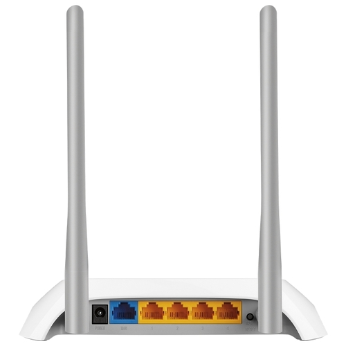
Подключите провод от провайдера к синему разъему, а кабель от компьютера или ноутбука к любому из желтых портов. Если собираетесь настраивать через беспроводную сеть, то посмотрите на нижнюю сторону устройства. Там есть наклейка, на которой написано название беспроводной сети и пароль от неё. Подключитесь к нему любым способом, а потом в адресной строке наберите http://tplinkwifi.net. Появится окно, в котором от вас потребуют создать новый пароль.

Если роутер просит ввести пароль, а не создать, то сбросьте его до заводских настроек. Для этого найдите кнопку WPS/RESET рядом с одной из антенн, нажмите на неё и держите около десяти секунд. Маршрутизатор перезагрузится и можно будет снова заходить в настройки. В этот раз придумайте пароль и запишите его куда-нибудь, чтобы не забыть. Теперь откроется окно с быстрыми настройками. Если этого не произошло, то в верхней части меню выберите раздел «Быстрая настройка».

В первом разделе выберите свою страну и оператора, если они есть. Если же их нет, то поставьте галку «Я не нашел подходящих настроек». Самым важным здесь является тип подключения, от него зависит то, какую информацию потребует от вас роутер. Лучше найдите тип подключения заранее в инструкции или договоре. Как закончите, переходите к следующему разделу. Если оператор и тип подключения определены, то следующий раздел перескочим, если нет, то там потребуется выбрать тип подключения.

Этот раздел зависит от того типа подключения, который используется у вашего оператора. Обычно требуется ввести логин и пароль, иногда нужен адрес сервера или что-то подобное. Найдите информацию в договоре или официальной инструкции.

Следующий раздел посвящен вайфаю. Поставьте галку, если хотите включить беспроводную сеть. В верхней строке введите имя сети, а в нижней укажите желаемый пароль от неё. Переходите к следующей вкладке, на ней проверьте все заданные параметры от провайдера и от беспроводной сети. Если все правильно, то жмите на «Сохранить» и ждите применения настроек.

Если что-то не получилось, то переходите в основные настройки и меняйте там параметры. Также есть расширенные дополнительные настройки, в них можно провести тонкую настройку оборудования.
Как прошить Wi-Fi роутер от TP-Link
Обновлять прошивку стоит для того, чтобы устройство быстрее работало и не накапливало ошибки. Также прошивка поможет в том случае, если у вас имеется «фирменный» роутер. Некоторые провайдеры выдавали такие роутеры, но на них нельзя было подключаться к другим операторам. После перепрошивки такая проблема исчезала.
Зайдите в Web-интерфейс через браузер и перейдите в раздел дополнительных настроек. В левой колонке выберите «Системные инструменты», а потом «Обновление встроенного ПО». В правой части окна появится предложение по автоматической загрузке или предложит подгрузить файл самостоятельно.

Попробуйте сначала найти прошивку через онлайн. Если не получилось, то идите на официальный сайт и ищите там свой роутер. Переходите в раздел загрузок и скачивайте прошивку. Не забудьте выбрать вашу версию роутера, чтобы скачать правильную программу. После загрузки нажмите в интерфейсе роутера кнопку «Обзор», укажите путь до загруженного файла, а потом кликните по «Обновить».
Отзывы пользователей о TL-WR850N
Отзывы имеются разные о нескольких версиях роутера.
Надежность
Простая настройка
Бесперебойная работа
Скорость провайдера до 100 Мбит/с
При подключении большого количества устройств начинает подтормаживать
Роутер хорош для своего времени или для мест, где скорость не поднимается выше сотни мегабит. Сам маршрутизатор слабоват для активного использования в больших сетях, но домашние нагрузки держит хорошо. Если хочется большой скорости, то стоит рассматривать современные модели.
English version of the article here
В данной статье мы Вам расскажем, как настроить роутер TP-Link TL-WR850N. Также мы подготовили для Вас видео.
Для настройки роутера :
1. Нужно включить роутер в розетку, вставить интернет-кабель (приходящий от нашего оборудования в квартиру) в синий порт роутера, а патчкорд в любой из желтых портов роутера и вторым концом в ноутбук или компьютер или подключиться по wi-fi сети (если роутер сброшен до заводских настроек, то имя и пароль от wi-fi сети указан снизу на наклейке роутера)
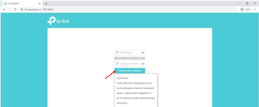
2. На ноутбуке/компьютере откройте браузер, введите в адресную строку адрес 192.168.0.1 и нажмите клавишу Enter. Откроется веб-интерфейс роутера. Вам сразу будет предложено создать пароль для входа в настройки роутера. Во избежание путаницы, мы советуем использовать пароль admin. Введите дважды пароль и нажмите кнопку «Приступим к работе»
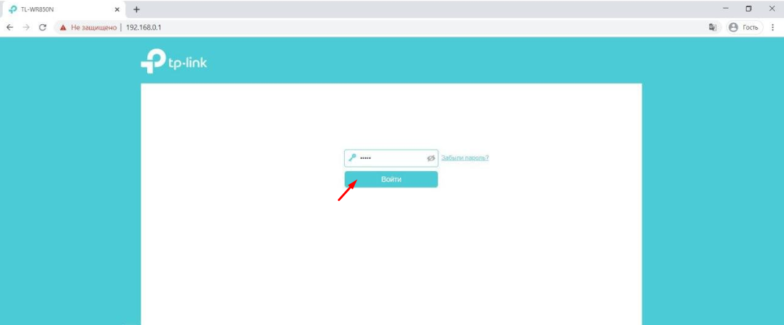
3. Теперь роутер «просит» Вас ввести пароль который Вы только что создали, чтобы Вы могли попасть к настройкам. Введите пароль и нажмите кнопку «Войти».
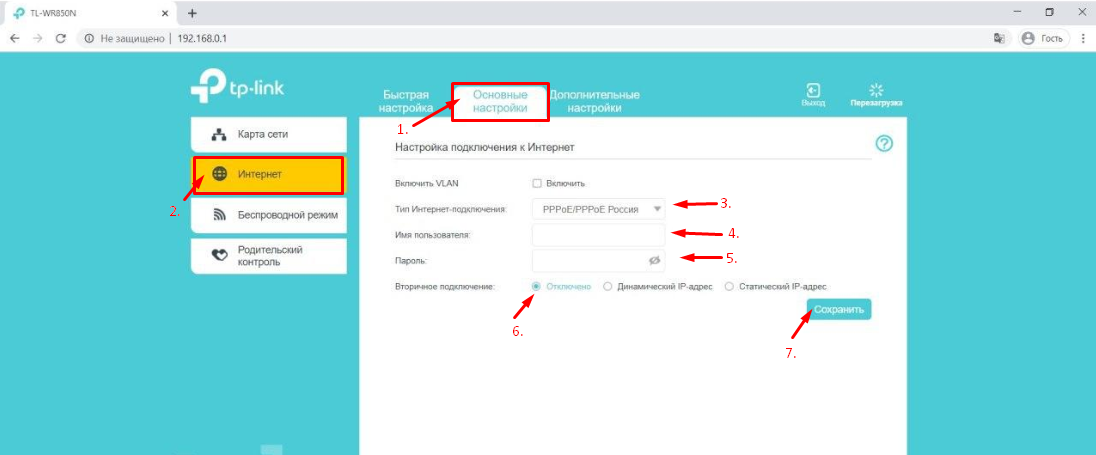
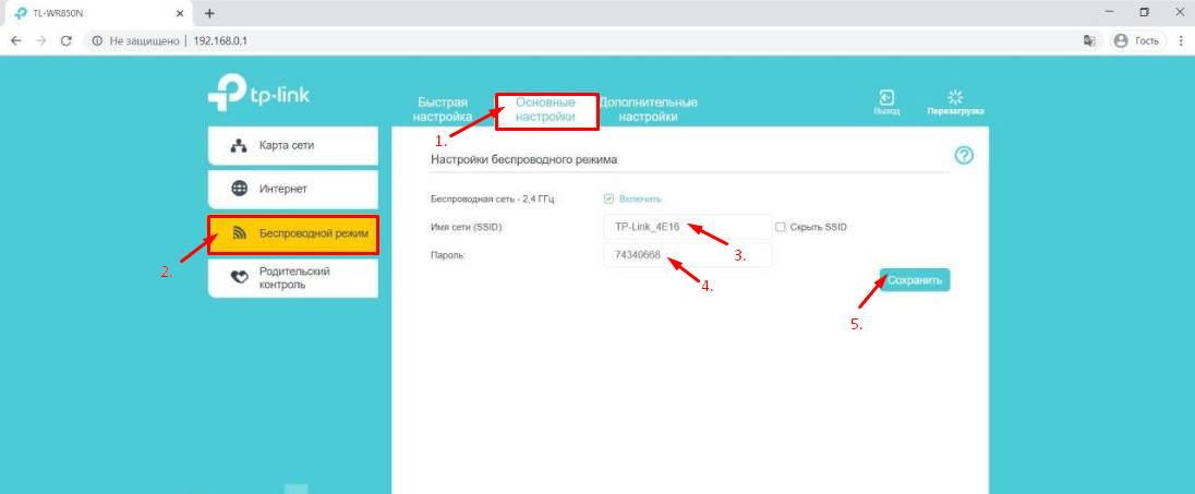
4. Теперь Вы попали в настройки роутера. В верхнем ряду выберите вкладку «Основные настройки».
5. После этого в меню слева выберите пункт «Интернет».
6. В пункте «Тип Интернет-подключения» в выпадающем меню выберите пункт «PPPoE/PPPoE Россия».
7. В появившихся полях «Имя пользователя» и «Пароль» Вам необходимо вписать Ваши логин и пароль от личного кабинета. После этого нажмите кнопку «Сохранить».
8. Следующий и последний шаг – настройка wifi. В меню слева выберите пункт «Беспроводной режим».
9. В поле «Имя сети (SSID)» необходимо внести название Вашей беспроводной сети (можно придумать любое название). В поле «Пароль» нужно ввести пароль который Вы хотите, он будет использоваться для подключения к wifi-сети (необходимо минимум 8 символов). Нажмите кнопку «Сохранить».
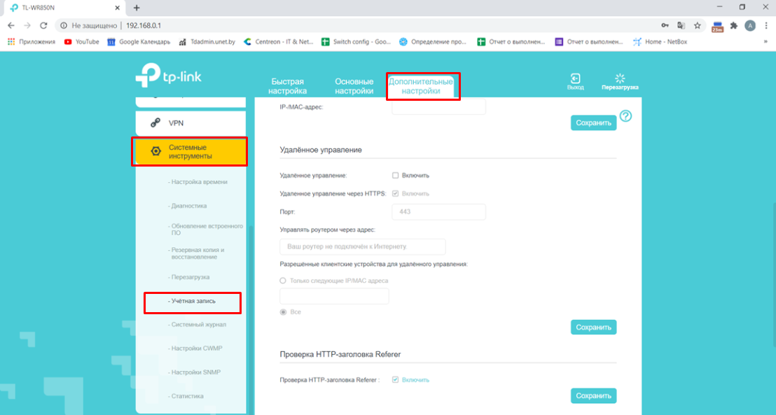
10. Настройка удаленного доступа.
Настройка удаленного доступа может понадобиться в разных ситуациях. Наши специалисты технической поддержки просят пользователей настроить удаленный доступ для проведения полной диагностики, а также, чтобы иметь возможность удаленно менять настройки роутера, управлять подключенным устройствами, выполнять перезагрузку роутера удаленно и т.д.
Переходим в меню «Дополнительные настройки» – «Системные инструменты» – «Учётная запись».
В открывшемся окне находим пункт «Удалённое управление»
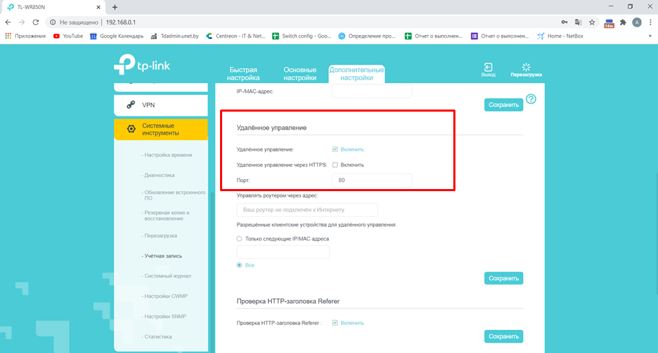
Ставим галочку напротив пункта «Удалённое управление: Включить» и убираем галочку с пункта «Удаленное управление через HTTPS: Включить»
Должно получиться так:
Далее отмечаем пункт «Только следующие IP/MAC адреса» и в поле ниже вписываем 10.82.200.40 (Для клиентов: Степянка, Дражня, Уручье, Копищи) или 10.77.43.43 (Для клиентов: Малиновка, Брилевичи), нажимаем кнопку «Сохранить»
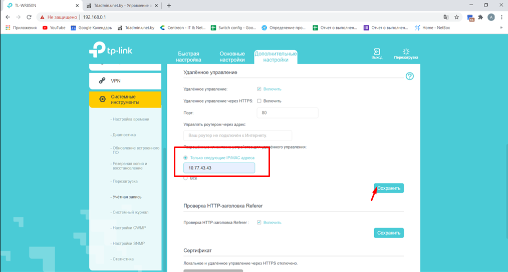
Все! Настройка закончена! Приятного пользования нашим интернетом! 
Подпишитесь на мобильное приложение: Viber, Telegram.
А также следите за актуальными новостями в нашем Telegram-канале.
Если у Вас возникли вопросы — напишите нам или позвоните 7778282 (любой мобильный оператор).
1. Подключите Ваш роутер к сети Internet (основному сетевому кабелю) и розетке.
2. Откройте браузер на устройстве и в адресной строке введите 192.168.0.1, либо зайдите на сайт TP-LINK.
3. В открывшемся окне введите заводские данные для доступа к настройкам:
— Имя пользователя: admin
— Пароль: admin

3. В левом меню зайдите во вкладку «Интернет» и затем откройте раздел «Основные настройки».
Проследите, чтобы в поле «Тип Интернет-подключения» был выбран Динамический IP-адрес. Если Вы выбрали его сами, то нажмите Сохранить.

4. Далее открываем раздел «Беспроводной режим» и Настройки беспроводного режима.
Имя сети (SSID) — это название Вашей сети Wi-Fi, которое можно поменять. Также необходимо придумать 8-значный пароль.

Когда всё сделаете, нажмите Сохранить и справа вверху нажмите Перезагрузка.
Когда роутер завершит перезагрузку, закройте окно с настройками, поищите на устройстве свою сеть и попробуйте к ней подключиться с паролем. Пароль куда-нибудь запишите, чтобы не потерять.
Подключение маршрутизатора для работы в сети
На верхней части маршрутизатора расположены следующие индикаторы (слева направо):
- Питание.
- Система.
- Беспроводное соединение.
- 2-й порт проводного соединения.
- 1-й порт проводного соединения.
- Интернет-соединение.
- WPS.
Сзади расположены порты для подключения блока питания, кабеля интернет-соединения (синего цвета), двух компьютеров (желтого цвета), а так же кнопка сброса, она же кнопка настройки WPS (Wi-Fi Protected Setup).
Для активации функции WPS держим кнопку нажатой менее 5 секунд, для сброса настроек – более 5 секунд.
На нижней стороне роутера можно найти отверстия для крепления на стену, а так же наклейку, на которой указан серийный номер маршрутизатора, MAC-адрес, пароль к беспроводному подключению по умолчанию, а так же адрес, логин и пароль для доступа к настройкам.
Настройка маршрутизатора
Обратите внимание! При настройке интернет на маршрутизаторе через смартфон или плашнет необходимо отключить мобильный интернет на устройстве, через которое проводится настройка. После чего подключить смартфон/планшет к маршрутизатору через Wi-Fi, используя пароль от Wi-Fi указанный на обратной стороне маршрутизатора. Далее приступить к ШАГУ №1.
Шаг 1. Открываем настройки маршрутизатора
Открываем браузер, вводим адрес http://192.168.0.1, либо http://tplinkwifi.net.
В появившемся окне вводим имя пользователя admin и пароль admin.
Если имя пользователя и пароль введены правильно, то после авторизации в браузере должна открыться главная страница – «Status»:
Шаг 2. Настраиваем соединение
- Переходим во вкладку Основные настройки.
- Далее по вкладке Интернет.
- В поле WAN Connection Type выбираем PPTP/Russia PPTP.
- В поле User Name/Имя пользователя вписываем Номер договора пользователя из договора.
- В поле Password/Пароль вписываем пароль из договора.
- Тип адреса выбираем Динамический IP-адрес.
- В поле Server IP Address/Имя VPN-сервера пишем vpn.ptech.by.
- Нажимаем кнопку [Save/Сохранить], чтобы сохранить введенные настройки.
Шаг 4. Настраиваем беспроводные сети Wi-Fi
Если Вы хотите подключаться к маршрутизатору не только с помощью кабеля, но и с помощью технологии Wi-Fi (например с ноутбука, планшета или смартфона), Вам необходимо произвести дополнительные Настройки. Для этого надо убедиться в том, что беспроводной режим включен, а также узнать название сети для подключения или задать собственное название для беспроводной сети.
Чтобы узнать название беспроводной сети или задать имена своих беспроводных сетей (поддерживается до 4х сетей одновременно, в каждой можно задать свои настройки безопасности, пароль доступа и т.д.), необходимо:
- Открываем вкладку — Дополнительные настройки.
- Беспроводной режим — Настройки беспроводного режима.
- Ставим галочку : Включить беспроводное вещание.
- Пишем Ваше собственное : НАЗВАНИЕ WI-FI.
- Придумываем 8-мизначный пароль и вписываем его в поле Пароль.
- После внесенных изменений нажимаем кнопку Сохранить.
Шаг 5. Применение параметров
Для того чтобы настройки вступили в силу требуется перезапустить роутер.

REV1.0.0 1910020829
User Guide
300Mbps Wireless N Router
TL—WR850N

Contents
About This Guide . . . . . . . . . . . . . . . . . . . . . . . . . . . . . . . . . . . . . . . . . . . . . . . . . . . . .1
Chapter 1. Get to Know About Your Router . . . . . . . . . . . . . . . . . . . . . . . . . . .2
1. 1. Product Overview. . . . . . . . . . . . . . . . . . . . . . . . . . . . . . . . . . . . . . . . . . . . . . . . . . . . . . . . . . . . 3
1. 2. Panel Layout. . . . . . . . . . . . . . . . . . . . . . . . . . . . . . . . . . . . . . . . . . . . . . . . . . . . . . . . . . . . . . . . . 3
1. 2. 1. Top View . . . . . . . . . . . . . . . . . . . . . . . . . . . . . . . . . . . . . . . . . . . . . . . . . . . . . . . . . . . . . . 3
1. 2. 2. The Back Panel. . . . . . . . . . . . . . . . . . . . . . . . . . . . . . . . . . . . . . . . . . . . . . . . . . . . . . . . 4
Chapter 2. Connect to the Internet . . . . . . . . . . . . . . . . . . . . . . . . . . . . . . . . . . .6
2. 1. Position Your Router . . . . . . . . . . . . . . . . . . . . . . . . . . . . . . . . . . . . . . . . . . . . . . . . . . . . . . . . . 7
2. 2. Connect to the Internet . . . . . . . . . . . . . . . . . . . . . . . . . . . . . . . . . . . . . . . . . . . . . . . . . . . . . . 7
Chapter 3. Log In. . . . . . . . . . . . . . . . . . . . . . . . . . . . . . . . . . . . . . . . . . . . . . . . . . . 10
Chapter 4. Configure the Router . . . . . . . . . . . . . . . . . . . . . . . . . . . . . . . . . . . 12
4. 1. Status . . . . . . . . . . . . . . . . . . . . . . . . . . . . . . . . . . . . . . . . . . . . . . . . . . . . . . . . . . . . . . . . . . . . . . 13
4. 2. Network . . . . . . . . . . . . . . . . . . . . . . . . . . . . . . . . . . . . . . . . . . . . . . . . . . . . . . . . . . . . . . . . . . . . 14
4. 2. 1. WAN. . . . . . . . . . . . . . . . . . . . . . . . . . . . . . . . . . . . . . . . . . . . . . . . . . . . . . . . . . . . . . . . 14
4. 2. 2. MAC Clone . . . . . . . . . . . . . . . . . . . . . . . . . . . . . . . . . . . . . . . . . . . . . . . . . . . . . . . . . . . 21
4. 2. 3. LAN . . . . . . . . . . . . . . . . . . . . . . . . . . . . . . . . . . . . . . . . . . . . . . . . . . . . . . . . . . . . . . . 21
4. 3. Wireless . . . . . . . . . . . . . . . . . . . . . . . . . . . . . . . . . . . . . . . . . . . . . . . . . . . . . . . . . . . . . . . . . . . . 22
4. 3. 1. Wireless Settings . . . . . . . . . . . . . . . . . . . . . . . . . . . . . . . . . . . . . . . . . . . . . . . . . . . . 22
4. 3. 2. WPS. . . . . . . . . . . . . . . . . . . . . . . . . . . . . . . . . . . . . . . . . . . . . . . . . . . . . . . . . . . . . . . . 24
4. 3. 3. Wireless Security . . . . . . . . . . . . . . . . . . . . . . . . . . . . . . . . . . . . . . . . . . . . . . . . . . . . 25
4. 3. 4. Wireless MAC Filtering . . . . . . . . . . . . . . . . . . . . . . . . . . . . . . . . . . . . . . . . . . . . . . . 27
4. 3. 5. Wireless Advanced. . . . . . . . . . . . . . . . . . . . . . . . . . . . . . . . . . . . . . . . . . . . . . . . . . . 28
4. 3. 6. Wireless Statistics . . . . . . . . . . . . . . . . . . . . . . . . . . . . . . . . . . . . . . . . . . . . . . . . . . . 29
4. 4. Guest Network. . . . . . . . . . . . . . . . . . . . . . . . . . . . . . . . . . . . . . . . . . . . . . . . . . . . . . . . . . . . . . 30
4. 5. DHCP. . . . . . . . . . . . . . . . . . . . . . . . . . . . . . . . . . . . . . . . . . . . . . . . . . . . . . . . . . . . . . . . . . . . . . . 31
4. 5. 1. DHCP Settings . . . . . . . . . . . . . . . . . . . . . . . . . . . . . . . . . . . . . . . . . . . . . . . . . . . . . . . 31
4. 5. 2. DHCP Client List . . . . . . . . . . . . . . . . . . . . . . . . . . . . . . . . . . . . . . . . . . . . . . . . . . . . . 32
4. 5. 3. Address Reservation . . . . . . . . . . . . . . . . . . . . . . . . . . . . . . . . . . . . . . . . . . . . . . . . . 33
4. 6. Forwarding . . . . . . . . . . . . . . . . . . . . . . . . . . . . . . . . . . . . . . . . . . . . . . . . . . . . . . . . . . . . . . . . . 33
4. 6. 1. Virtual Server . . . . . . . . . . . . . . . . . . . . . . . . . . . . . . . . . . . . . . . . . . . . . . . . . . . . . . . . 34
4. 6. 2. Port Triggering . . . . . . . . . . . . . . . . . . . . . . . . . . . . . . . . . . . . . . . . . . . . . . . . . . . . . . . 35

4. 6. 3. DMZ. . . . . . . . . . . . . . . . . . . . . . . . . . . . . . . . . . . . . . . . . . . . . . . . . . . . . . . . . . . . . . . . 36
4. 6. 4. UPnP. . . . . . . . . . . . . . . . . . . . . . . . . . . . . . . . . . . . . . . . . . . . . . . . . . . . . . . . . . . . . . . . 37
4. 7. Security . . . . . . . . . . . . . . . . . . . . . . . . . . . . . . . . . . . . . . . . . . . . . . . . . . . . . . . . . . . . . . . . . . . . 38
4. 7. 1. Basic Security. . . . . . . . . . . . . . . . . . . . . . . . . . . . . . . . . . . . . . . . . . . . . . . . . . . . . . . . 38
4. 7. 2. Advanced Security . . . . . . . . . . . . . . . . . . . . . . . . . . . . . . . . . . . . . . . . . . . . . . . . . . . 39
4. 7. 3. Local Management. . . . . . . . . . . . . . . . . . . . . . . . . . . . . . . . . . . . . . . . . . . . . . . . . . . 40
4. 7. 4. Remote Management . . . . . . . . . . . . . . . . . . . . . . . . . . . . . . . . . . . . . . . . . . . . . . . . 41
4. 8. Parental Controls . . . . . . . . . . . . . . . . . . . . . . . . . . . . . . . . . . . . . . . . . . . . . . . . . . . . . . . . . . . 42
4. 9. Access Control . . . . . . . . . . . . . . . . . . . . . . . . . . . . . . . . . . . . . . . . . . . . . . . . . . . . . . . . . . . . . 43
4. 10. Advanced Routing . . . . . . . . . . . . . . . . . . . . . . . . . . . . . . . . . . . . . . . . . . . . . . . . . . . . . . . . . . 45
4. 10. 1. Static Route List . . . . . . . . . . . . . . . . . . . . . . . . . . . . . . . . . . . . . . . . . . . . . . . . . . . . 45
4. 10. 2. System Routing Table . . . . . . . . . . . . . . . . . . . . . . . . . . . . . . . . . . . . . . . . . . . . . . . 46
4. 11. Bandwidth Control . . . . . . . . . . . . . . . . . . . . . . . . . . . . . . . . . . . . . . . . . . . . . . . . . . . . . . . . . . 47
4. 11. 1. Control Settings . . . . . . . . . . . . . . . . . . . . . . . . . . . . . . . . . . . . . . . . . . . . . . . . . . . . 47
4. 11. 2. Rule List . . . . . . . . . . . . . . . . . . . . . . . . . . . . . . . . . . . . . . . . . . . . . . . . . . . . . . . . . . . . 47
4. 12. IP & MAC Binding . . . . . . . . . . . . . . . . . . . . . . . . . . . . . . . . . . . . . . . . . . . . . . . . . . . . . . . . . . . 48
4. 12. 1. Binding Settings . . . . . . . . . . . . . . . . . . . . . . . . . . . . . . . . . . . . . . . . . . . . . . . . . . . . 48
4. 12. 2. ARP List . . . . . . . . . . . . . . . . . . . . . . . . . . . . . . . . . . . . . . . . . . . . . . . . . . . . . . . . . . . . 49
4. 13. Dynamic DNS. . . . . . . . . . . . . . . . . . . . . . . . . . . . . . . . . . . . . . . . . . . . . . . . . . . . . . . . . . . . . . . 50
4. 14. IPv6 . . . . . . . . . . . . . . . . . . . . . . . . . . . . . . . . . . . . . . . . . . . . . . . . . . . . . . . . . . . . . . . . . . . . . . . . 52
4. 14. 1. IPv6 Status . . . . . . . . . . . . . . . . . . . . . . . . . . . . . . . . . . . . . . . . . . . . . . . . . . . . . . . . . 52
4. 14. 2. IPv6 WAN . . . . . . . . . . . . . . . . . . . . . . . . . . . . . . . . . . . . . . . . . . . . . . . . . . . . . . . . . . . 53
4. 14. 3. IPv6 LAN. . . . . . . . . . . . . . . . . . . . . . . . . . . . . . . . . . . . . . . . . . . . . . . . . . . . . . . . . . . . 56
4. 15. System Tools . . . . . . . . . . . . . . . . . . . . . . . . . . . . . . . . . . . . . . . . . . . . . . . . . . . . . . . . . . . . . . . 57
4. 15. 1. Time Settings . . . . . . . . . . . . . . . . . . . . . . . . . . . . . . . . . . . . . . . . . . . . . . . . . . . . . . . 57
4. 15. 2. Diagnostic . . . . . . . . . . . . . . . . . . . . . . . . . . . . . . . . . . . . . . . . . . . . . . . . . . . . . . . . . . 58
4. 15. 3. CWMP Settings . . . . . . . . . . . . . . . . . . . . . . . . . . . . . . . . . . . . . . . . . . . . . . . . . . . . . 59
4. 15. 4. Firmware Upgrade . . . . . . . . . . . . . . . . . . . . . . . . . . . . . . . . . . . . . . . . . . . . . . . . . . 61
4. 15. 5. Factory Defaults . . . . . . . . . . . . . . . . . . . . . . . . . . . . . . . . . . . . . . . . . . . . . . . . . . . . 61
4. 15. 6. Backup & Restore . . . . . . . . . . . . . . . . . . . . . . . . . . . . . . . . . . . . . . . . . . . . . . . . . . . 62
4. 15. 7. Reboot . . . . . . . . . . . . . . . . . . . . . . . . . . . . . . . . . . . . . . . . . . . . . . . . . . . . . . . . . . . . . 62
4. 15. 8. Password . . . . . . . . . . . . . . . . . . . . . . . . . . . . . . . . . . . . . . . . . . . . . . . . . . . . . . . . . . . 63
4. 15. 9. System Log. . . . . . . . . . . . . . . . . . . . . . . . . . . . . . . . . . . . . . . . . . . . . . . . . . . . . . . . . 63
4. 15. 10. Statistics . . . . . . . . . . . . . . . . . . . . . . . . . . . . . . . . . . . . . . . . . . . . . . . . . . . . . . . . . . 64
4. 16. Log Out. . . . . . . . . . . . . . . . . . . . . . . . . . . . . . . . . . . . . . . . . . . . . . . . . . . . . . . . . . . . . . . . . . . . . 65
FAQ . . . . . . . . . . . . . . . . . . . . . . . . . . . . . . . . . . . . . . . . . . . . . . . . . . . . . . . . . . . . . . . 67

1
About This Guide
This guide is a complement to Quick Installation Guide. The Quick Installation Guide
provides instructions for quick Internet setup, while this guide contains details of each
function and demonstrates how to configure them.
When using this guide, please notice that features of the router may vary slightly
depending on the model and software version you have, and on your location, language,
and Internet service provider. All screenshots, images, parameters and descriptions
documented in this guide are used for demonstration only.
Conventions
In this guide the following conventions are used:
Convention Description
Underlined Underlined words or phrases are hyperlinks. You can click to redirect to a website or a
specific section.
Teal Contents to be emphasized and texts on the web page are in teal, including the menus,
items, buttons and so on.
>
The menu structures to show the path to load the corresponding page. For example,
Advanced > Wireless > MAC Filtering means the MAC Filtering function page is under the
Wireless menu that is located in the Advanced tab.
Note: Ignoring this type of note might result in a malfunction or damage to the device.
Tips: Indicates important information that helps you make better use of your device.
More Info
The latest software, management app and utility are available from the Download
Center at www.tp-link.com/support.
The Quick Installation Guide can be found where you find this guide or inside the
package of the router.
Specifications can be found on the product page at http://www.tp-link.com.
A Technical Support Forum is provided for you to discuss our products at
http://forum.tp-link.com.
Our Technical Support contact information can be found at the Contact Technical
Support page at www.tp-link.com/support.

Chapter 1
Get to Know About Your
Router
This chapter introduces what the router can do and shows its appearance.
It contains the following sections:
• Product Overview
• Panel Layout
3
Chapter 1 Get to Know About Your Router
1. 1. Product Overview
The TP-Link router is designed to fully meet the need of Small Office/Home Office
(SOHO) networks and users demanding higher networking performance. The powerful
antennas ensure continuous Wi-Fi signal to all your devices while boosting widespread
coverage throughout your home, and the built-in Ethernet ports supply high-speed
connection to your wired devices.
Moreover, it is simple and convenient to set up and use the TP-Link router due to its
intuitive web interface.
1. 2. Panel Layout
1. 2. 1. Top View
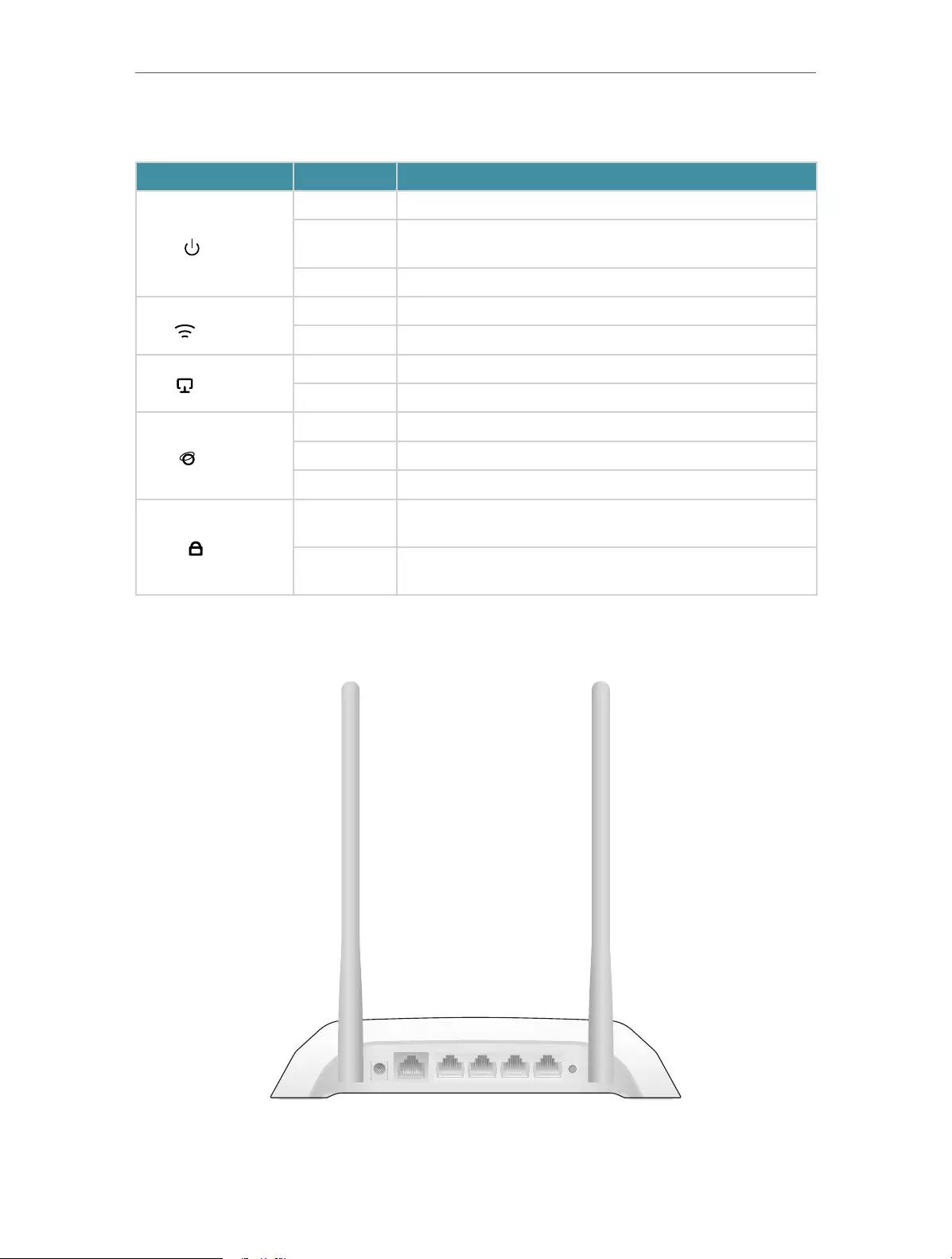
The router’s LEDs (view from left to right) are located on the front panel. You can check
the router’s working status by following the LED Explanation table.
4
Chapter 1 Get to Know About Your Router
LED Explanation
Name Status Indication
(Power)
On System initialization completes.
Flashing System initialization or firmware upgrade is in progress. Do not
disconnect or power off the router.
Off Power is off.
(Wireless)
On The wireless function is working properly.
Off The wireless function is disabled.
(Ethernet)
On One of LAN ports is connected.
Off No LAN port is connected.
(Internet)
Blue On The Internet is available.
Orange On The router’s WAN port is connected, but the Internet is not available.
Off The router’s WAN port is not connected.
(WPS)
On/Off Turns on when WPS connection is established, and goes off about 5
minutes later.
Flashing A wireless device is trying to connect to the network via WPS. This
process may take up to 2 minutes.
1. 2. 2. The Back Panel
WPS/
RESET
2 3WAN 1 4
POWER
The following parts (view from left to right) are located on the rear panel.

5
Chapter 1 Get to Know About Your Router
Item Description
Power Port For connecting the router to a power socket via the provided power adapter.
WAN Port For connecting to a DSL/Cable modem, or an Ethernet port.
Ethernet Ports (1/2/3/4) For connecting your PCs or other wired network devices to the router.
WPS/Reset Button
Press and hold this button until all the LED turn on momentarily to reset the router to
its factory default settings.
To enable the WPS function, press this button about 2 seconds. If you have a WPS—
supported device, you can press this button to quickly establish connection between
the router and the client device and automatically configure wireless security for your
wireless network.
Antennas Used for wireless operation and data transmitting. Upright them for the best Wi-Fi
performance.

Chapter 2
Connect to the Internet
This chapter contains the following sections:
• Position Your Router
• Connect to the Internet
7
Chapter 2 Connect to the Internet
2. 1. Position Your Router
• The product should not be located in a place where it will be exposed to moisture or
excessive heat.
• Place the router in a location where it can be connected to multiple devices as well as
to a power source.
• Make sure the cables and power cord are safely placed out of the way so they do not
create a tripping hazard.
• The router can be placed on a shelf or desktop.
• Keep the router away from strong devices with strong electromagnetic interference,
such as Bluetooth devices, cordless phones and microwaves.
2. 2. Connect to the Internet
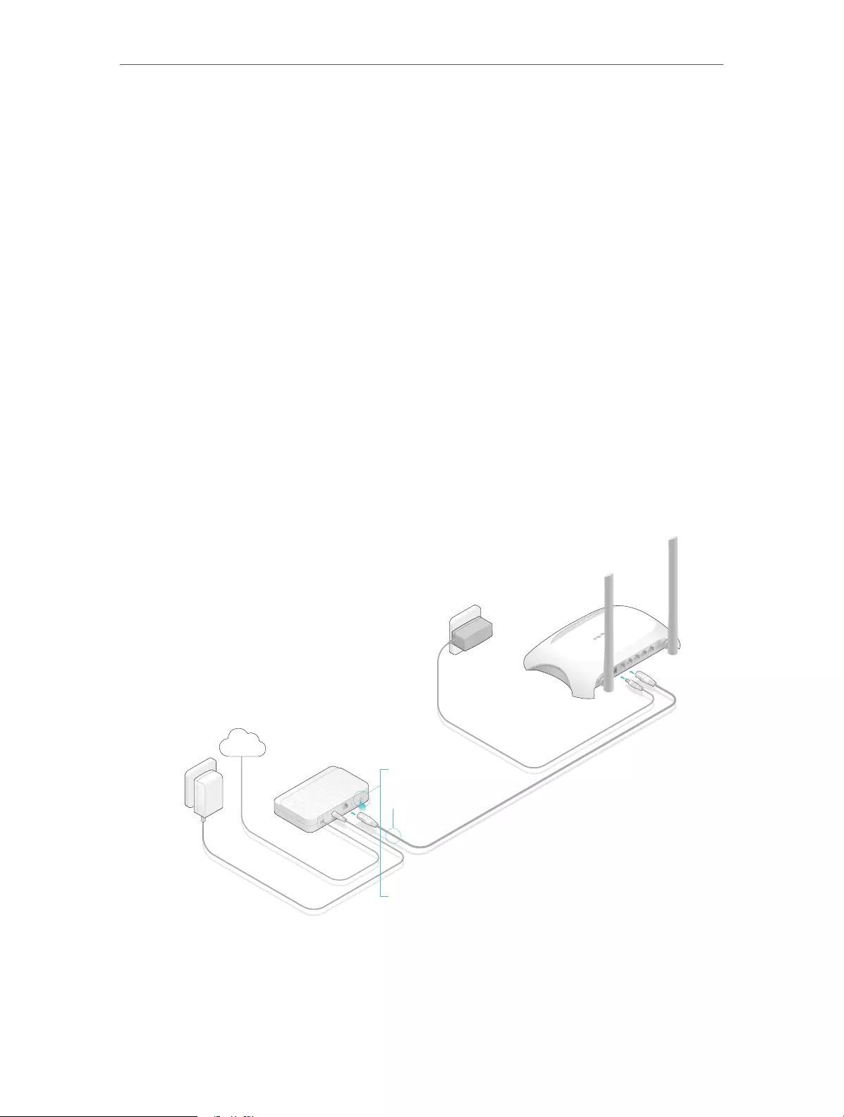
Follow the steps below to connect your router.
If your Internet connection is through an Ethernet cable from the wall instead of through
a DSL / Cable / Satellite modem, connect the Ethernet cable directly to the router’s
WAN port, and then follow Step 4 and 5 to complete the hardware connection.
Modem
Power adapter
Router
Power adapter
4
3
2
Internet
POWER WAN 1 2 3 4
WPS/
RESET
POWER WAN 1 2 3 4
WPS/
RESET
1
1 ) Turn off the modem, and remove the backup battery if it has one.
2 ) Connect the modem to the WAN port on your router with an Ethernet cable.
3 ) Turn on the modem, and then wait about 2 minutes for it to restart.
8
Chapter 2 Connect to the Internet
1 ) Connect the power adapter to the router and turn on the router.
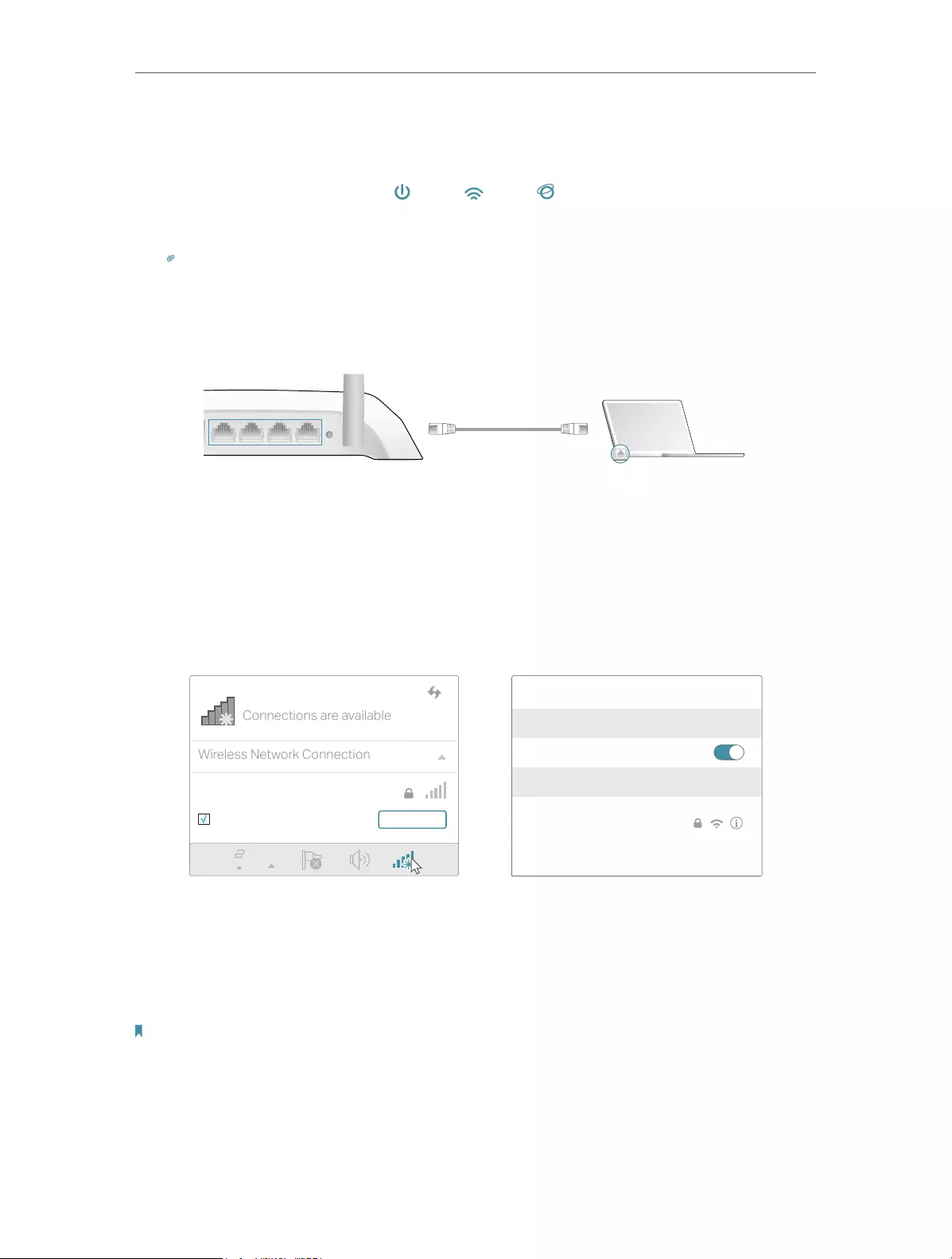
2 ) Verify that the hardware connection is correct by checking these LEDs.
Power
On
Internet
On
Wi-Fi
On
Tips: If Wi-Fi LED is off, enable the Wi-Fi function by using a web browser.
1. Connect your computer to the router.
• Method 1: Wired
Turn off the Wi-Fi on your computer and connect the devices as shown below.
WPS/
RESET
2 31 4
Ethernet cable
• Method 2: Wirelessly
1 ) Find the SSID (Network Name) and Wireless Password printed on the label at
the bottom of the router.
2 ) Click the network icon of your computer or go to Wi-Fi Settings of your smart
device, and then select the SSID to join the network.
OR
Connections are available
Wireless Network Connection
TP-LINK_XXXX
Connect automatically Connect
Wi-Fi
Wi-Fi
TP-LINK_XXXX
CHOOSE A NETWORK…
Other…
< Settings
Smart DeviceComputer
• Method 3: Use the WPS button
Wireless devices that support WPS, including Android phones, tablets, most USB
network cards, can be connected to your router through this method ( Not supported
by iOS devices).
Note:
The WPS function cannot be configured if the wireless function of the router is disabled. Also, the WPS function will be
disabled if your wireless encryption is WEP. Please make sure the wireless function is enabled and is configured with the
appropriate encryption before configuring the WPS.
9
Chapter 2 Connect to the Internet
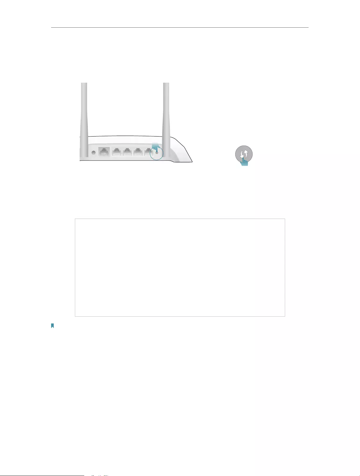
1 ) Tab the WPS icon on the device’s screen, here takes an Android phone as an
example.
2 ) Immediately press the WPS button on your router.
WPS/
RESET
2 3WAN 1 4
POWER
Close to
1. Enter http://tplinkwifi.net in the address bar of a web browser. Use admin for both
username and password, and then click Login.
Note:
If the above screen does not pop-up, it means that your IE Web-browser has been set to a proxy. Go to Tools menu >
Internet Options > Connections > LAN Settings, in the screen that appears, cancel the Using Proxy checkbox, and click
OK to finish it.
2. After successfully login, select Standard Wireless Router mode and follow Quick
Setup to complete the configuration.
3. Enjoy! For wireless devices, you may have to reconnect to the wireless network if you
have customized the SSID (wireless name) and password during the configuration.

Chapter 3
Log In
This chapter introduces how to log in to the web management page of router.

11
Chapter 3 Log In
With the web-based utility, it is easy to configure and manage the router. The web-
based utility can be used on any Windows, Macintosh or UNIX OS with a Web browser,
such as Microsoft the Internet Explorer, Mozilla Firefox or Apple Safari.
Follow the steps below to log in to your router.
1. Set up the TCP/IP Protocol in Obtain an IP address automatically mode on your computer.
2. Visit http://tplinkwifi.net, and log in with the username and password you set for the router.
The default one is admin (all lowercase) for both username and password.
Note:
If the login window does not appear, please refer to the “FAQ” section.

Chapter 4
Configure the Router
This chapter presents how to configure the various features of the router.
It contains the following sections:
• Status
• Network
• Wireless
• Guest Network
• DHCP
• Forwarding
• Security
• Parental Controls
• Access Control
• Advanced Routing
• Bandwidth Control
• IP & MAC Binding
• Dynamic DNS
• IPv6
• System Tools
• Log Out
13
Chapter 4 Congure the Router
4. 1. Status
1. Visit http://tplinkwifi.net, and log in with the username and password you set for the
router.
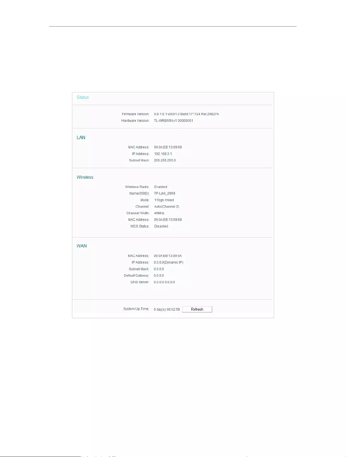
2. Go to Status. You can view the current status information of the router.
• Firmware Version — The version information of the router’s firmware.
• Hardware Version — The version information of the router’s hardware.
• LAN — This field displays the current settings of the LAN, and you can configure them
on the Network > LAN page.
• MAC address — The physical address of the router.
• IP address — The LAN IP address of the router.
• Subnet Mask — The subnet mask associated with the LAN IP address.
• Wireless — This field displays the basic information or status of the wireless function,
and you can configure them on the Wireless > Wireless Settings page.

14
Chapter 4 Congure the Router
• Wireless Radio — Indicates whether the wireless feature is enabled or not.
• Name (SSID) — The SSID of the router.
• Mode — The current wireless working mode in use.
• Channel Width — The current wireless channel width in use.
• Channel — The current wireless channel in use.
• MAC Address — The physical address of the router.
• WDS Status — The status of WDS connection.
• WAN — This field displays the current settings of the WAN, and you can configure them
on the Network > WAN page.
• MAC Address — The physical address of the WAN port.
• IP Address — The current WAN (Internet) IP Address. This field will be blank
or 0.0.0.0 if the IP Address is assigned dynamically and there is no Internet
connection.
• Subnet Mask — The subnet mask associated with the WAN IP Address.
• Default Gateway — The Gateway currently used is shown here. When you use
Dynamic IP as the Internet connection type, click Renew or Release here to
obtain new IP parameters dynamically from the ISP or release them.
• DNS Server — The IP addresses of DNS (Domain Name System) server.
• System Up Time — The length of the time since the router was last powered on or
reset.
Click Refresh to get the latest status and settings of the router.
4. 2. Network
4. 2. 1. WAN
1. Visit http://tplinkwifi.net, and log in with the username and password you set for the
router.
2. Go to Network > WAN.
3. Configure the IP parameters of the LAN and click Save.
Dynamic IP
If your ISP provides the DHCP service, please select Dynamic IP, and the router will
automatically get IP parameters from your ISP.
Click Renew to renew the IP parameters from your ISP.
4. Click Release to release the IP parameters.Click Next to start. Then follow the step-
by-step instructions to connect your router to the internet.

15
Chapter 4 Congure the Router
• MTU Size — The normal MTU (Maximum Transmission Unit) value for most Ethernet
networks is 1500 Bytes. It is not recommended that you change the default MTU size
unless required by your ISP.
• Set DNS server manually — If your ISP gives you one or two DNS IP addresses, select
Set DNS server manually and enter the DNS Server and Secondary DNS Server into
the correct fields. Otherwise, the DNS servers will be assigned from ISP dynamically.
• Primary DNS — Enter the DNS IP address in dotted-decimal notation provided by
your ISP.
• Secondary DNS — Enter another DNS IP address in dotted-decimal notation
provided by your ISP.
• Host Name — This option specifies the name of the router.
• Get IP with Unicast DHCP — A few ISPs’ DHCP servers do not support the broadcast
applications. If you cannot get the IP address normally, you can choose this option. (It
is rarely required.)
Static IP
If your ISP provides a static or fixed IP address, subnet mask, default gateway and DNS
setting, please select Static IP.

16
Chapter 4 Congure the Router
• IP Address — Enter the IP address in dotted—decimal notation provided by your ISP.
• Subnet Mask — Enter the subnet mask in dotted—decimal notation provided by your
ISP. Normally 255.255.255.0 is used as the subnet mask.
• Gateway — Enter the gateway IP address in dotted—decimal notation provided by your
ISP.
• MTU Size — The normal MTU (Maximum Transmission Unit) value for most Ethernet
networks is 1500 Bytes. It is not recommended that you change the default MTU size
unless required by your ISP.
• Primary/Secondary DNS — (Optional) Enter one or two DNS addresses in dotted—
decimal notation provided by your ISP.
PPPoE
If your ISP provides PPPoE connection, select PPPoE.
• User Name/Password — Enter the user name and password provided by your ISP.
These fields are case-sensitive.

17
Chapter 4 Congure the Router
• Confirm Password — Enter the Password provided by your ISP again to ensure the
password you entered is correct.
• Secondary Connection — It’s available only for PPPoE connection. If your ISP provides
an extra connection type, select Dynamic IP or Static IP to activate the secondary
connection.
• Connection Mode
• Always on — Connect automatically after the Router is disconnected. To use this
option, click the radio button.
• Connect on demmand — You can configure the Router to disconnect your Internet
connection after a specified period of the Internet connectivity (Max Idle Time).
If your Internet connection has been terminated due to inactivity, Connect on
Demand enables the Router to automatically re-establish your connection
when you attempt to access the Internet again. If you wish to activate Connect
on Demand, put a check mark in the circle. If you want your Internet connection
to remain active all the times, enter 0 in the Max Idle Time field.
• Connect Manually — You can click Connect/Disconnect to connect/disconnect
immediately. This mode also supports the Max Idle Time function as Connect
on Demand mode. The Internet connection can be disconnected automatically
after a specified inactivity period (Max Idle Time) and not be able to re-establish
when you attempt to access the Internet again.
Note:
• Only when you have configured the system time on the System Tools > Time Settings page, will the
time-based connecting function take effect.
• Sometimes the connection cannot be terminated although you have specified the Max Idle Time because
some applications are visiting the Internet continually in the background.
If you want to do some advanced configurations, please click Advanced.
• MTU — The default MTU size is 1480 bytes. It is not recommended that you change the
default MTU size unless required by your ISP.
• Service Name/Server Name — The service name and server name should not be
configured unless you are sure it is necessary for your ISP. In most cases, leaving
these fields blank will work.

18
Chapter 4 Congure the Router
• ISP Specified IP Address — If your ISP does not automatically assign IP addresses to
the router, please select Use IP address specified by ISP and enter the IP address
provided by your ISP in dotted-decimal notation.
• Echo request interval — The router will detect Access Concentrator online at every
interval. The default value is 0. You can input the value between 0 and 120. The value
0 means no request.
• Set DNS server manually — If your ISP does not automatically assign DNS addresses to
the router, please select Set DNS server manually and enter the IP address in dotted—
decimal notation of your ISP’s primary DNS server. If a secondary DNS server address
is available, enter it as well.
BigPond Cable
If your ISP provides BigPond cable connection, please select BigPond Cable.
• User Name/Password — Enter the user name and password provided by your ISP.
These fields are case-sensitive.
• Auth Server — Enter the authenticating server IP address or host name.
• Auth Domain — Type in the domain suffix server name based on your location.
• MTU — The default MTU is 1480 bytes. It is not recommended that you change the
default MTU size unless required by your ISP.
• Connection Mode
• Connect on Demand — In this mode, the Internet connection can be terminated
automatically after a specified inactivity period (Max Idle Time) and be re-
established when you attempt to access the Internet again. If you want to keep
your Internet connection active all the time, please enter 0 in the Max Idle Time

19
Chapter 4 Congure the Router
field. Otherwise, enter the number of minutes you want to have elapsed before
your Internet access disconnects.
• Always on — Connect automatically after the Router is disconnected. To use this
option, click the radio button.
• Connect Manually — You can click Connect/Disconnect to connect/disconnect
immediately. This mode also supports the Max Idle Time function as Connect
on Demand mode. The Internet connection can be disconnected automatically
after a specified inactivity period (Max Idle Time) and not be able to re-establish
when you attempt to access the Internet again.
Note:
Sometimes the connection cannot be terminated although you have specified the Max Idle Time because some
applications are visiting the Internet continually in the background.
L2TP
If your ISP provides L2TP connection, please select L2TP.
• User Name/Password — Enter the user name and password provided by your ISP.
These fields are case-sensitive.
• Connect/Disconnect — Click this button to connect or disconnect immediately.
• Dynamic IP/ Static IP — Select either as required by your ISP. If Static IP is selected,
please enter the IP address, subnet marsk, gateway and DNS also provided by your
ISP.
• Internet IP Address/ Internet DNS — The Internet IP address and DNS server address
assigned by L2TP server.

20
Chapter 4 Congure the Router
• Connection Mode
• Connect on Demand — In this mode, the Internet connection can be terminated
automatically after a specified inactivity period (Max Idle Time) and be re-
established when you attempt to access the Internet again. If you want to keep
your Internet connection active all the time, please enter 0 in the Max Idle Time
field. Otherwise, enter the number of minutes you want to have elapsed before
your Internet access disconnects.
• Always on — Connect automatically after the Router is disconnected. To use this
option, click the radio button.
• Connect Manually — You can click Connect/Disconnect to connect/disconnect
immediately. This mode also supports the Max Idle Time function as Connect
on Demand mode. The Internet connection can be disconnected automatically
after a specified inactivity period (Max Idle Time) and not be able to re-establish
when you attempt to access the Internet again.
Note:
Sometimes the connection cannot be terminated although you have specified the Max Idle Time because some
applications are visiting the Internet continually in the background.
PPTP
If your ISP provides PPTP connection, please select PPTP.
• User Name/Password — Enter the user name and password provided by your ISP.
These fields are case-sensitive.
• Connect/Disconnect — Click this button to connect or disconnect immediately.

21
Chapter 4 Congure the Router
• Dynamic IP/ Static IP — Select either as required by your ISP. If Static IP is selected,
please enter the IP address, subnet marsk, gateway and DNS also provided by your
ISP.
• Internet IP Address/ Internet DNS — The Internet IP address and DNS server address
assigned by L2TP server.
• Connection Mode
• Connect on Demand — In this mode, the Internet connection can be terminated
automatically after a specified inactivity period (Max Idle Time) and be re-
established when you attempt to access the Internet again. If you want to keep
your Internet connection active all the time, please enter 0 in the Max Idle Time
field. Otherwise, enter the number of minutes you want to have elapsed before
your Internet access disconnects.
• Always on — Connect automatically after the Router is disconnected. To use this
option, click the radio button.
• Connect Manually — You can click Connect/Disconnect to connect/disconnect
immediately. This mode also supports the Max Idle Time function as Connect
on Demand mode. The Internet connection can be disconnected automatically
after a specified inactivity period (Max Idle Time) and not be able to re-establish
when you attempt to access the Internet again.
Note:
Sometimes the connection cannot be terminated although you have specified the Max Idle Time because some
applications are visiting the Internet continually in the background.
4. 2. 2. MAC Clone
1. Visit http://tplinkwifi.net, and log in with the username and password you set for the
router.
2. Go to Network > MAC Clone.
3. Configure the WAN MAC address and click Save.
• WAN MAC Address — This field displays the current MAC address of the WAN port.
If your ISP requires you to register the MAC address, please enter the correct MAC
address in this field. Click Restore Factory MAC to restore the MAC address of WAN
port to the factory default value.
22
Chapter 4 Congure the Router
• Your PC’s MAC Address — This field displays the MAC address of the PC that is
managing the router. If the MAC address is required, you can click Clone MAC Address
and this MAC address will be filled in the WAN MAC Address field.
Note:
• You can only use the MAC Address Clone function for PCs on the LAN.
• If you have changed the WAN MAC address when the WAN connection is PPPoE, it will not take effect
until the connection is re-established.
4. 2. 3. LAN
1. Visit http://tplinkwifi.net, and log in with the username and password you set for the
router.
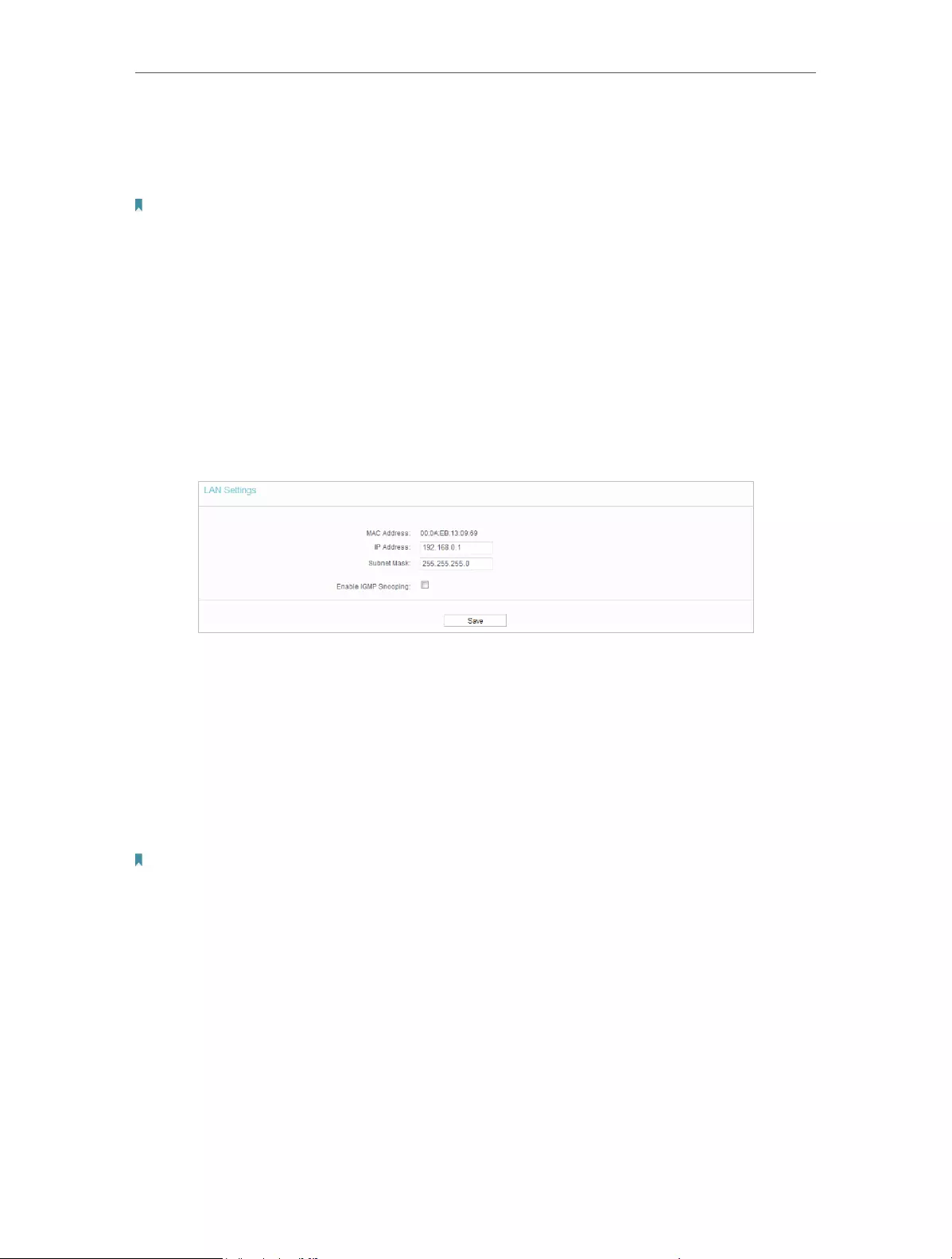
2. Go to Network > LAN.
3. Configure the IP parameters of the LAN and click Save.
• MAC Address — The physical address of the LAN ports. The value can not be changed.
• IP Address — Enter the IP address in dotted—decimal notation of your router (factory
default — 192.168.0.1).
• Subnet Mask — An address code that determines the size of the network. Normally
255.255.255.0 is used as the subnet mask.
• Enable IGMP Snooping — The Internet Group Management Protocol (IGMP) feature
allow you to watch TV on IPTV-supported devices on the LAN .
Note:
• If you have changed the IP address, you must use the new IP address to log in.
• If the new IP address you set is not in the same subnet as the old one, the IP address pool in the DHCP
Server will be configured automatically, but the Virtual Server and DMZ Host will not take effect until they
are re-configured.
4. 3. Wireless
4. 3. 1. Wireless Settings
1. Visit http://tplinkwifi.net, and log in with the username and password you set for the
router.
2. Go to Wireless > Basic Settings.

23
Chapter 4 Congure the Router
• Wireless Network Name — Enter a string of up to 32 characters. The default SSID is
TP-LINK_XXXX (XXXX indicates the last unique four numbers of each router’s MAC
address). It is strongly recommended that you change your network name (SSID). This
value is case-sensitive. For example, TEST is NOT the same as test.
• Mode — Select the desired mode. It is strongly recommended that you keep the
default setting 11bgn mixed, so that all 802.11b/g/n wireless devices can connect to
the router.
Note:
If 11bg mixed mode is selected, the Channel Width field will turn grey and the value will become 20M, and cannot be
changed.
• Channel Width — Select any channel width from the drop-down list. The default setting
is Auto, which can automatically adjust the channel width for your clients.
• Channel — This field determines which operating frequency will be used. The default
channel is set to Auto. It is not necessary to change the wireless channel unless you
notice interference problems with another nearby access point.
• Enable SSID Broadcast — If enabled, the router will broadcast the wireless network
name (SSID).
• Enable WDS — You can select this to enable WDS Bridging, with this function, the router
can bridge two or more WLANs.
Note:
If this checkbox is selected, you had better make sure the following settings are correct.
• SSID (to be bridged) — The SSID of the AP your router is going to connect to as a client.
You can also use the survey function to select the SSID to join.

24
Chapter 4 Congure the Router
• MAC Address (to be bridged) — The MAC Address of the AP your Router is going to
connect to as a client. You can also use the scan function to select the MAC Address
to join.
• Scan — Click this button, you can search the AP which runs currently.
• Key type — This option should be chosen according to the AP’s security configuration.
It is recommended that the security type is the same as your AP’s security type.
• WEP Index — This option should be chosen if the key type is WEP (ASCII) or WEP (HEX).
It indicates the index of the WEP key.
• Authentication Type — This option should be chosen if the key type is WEP (ASCII) or
WEP (HEX).It indicates the authorization type of the Root AP.
• Password — If the AP your router is going to connect needs password, you need to fill
the password in this blank.
4. 3. 2. WPS
WPS (Wi-Fi Protected Setup) can help you to quickly and securely connect to a network.
This section will guide you to add a new wireless device to your router’s network quickly
via WPS.
Note:
The WPS function cannot be configured if the wireless function of the router is disabled. Please make sure the wireless
function is enabled before configuration.
1. Visit http://tplinkwifi.net, and log in with the username and password you set for the
router.
2. Go to WPS.
3. Follow one of the following three methods to connect your client device to the
router’s Wi-Fi network.
Method ONE: Press the WPS Button on Your Client Device
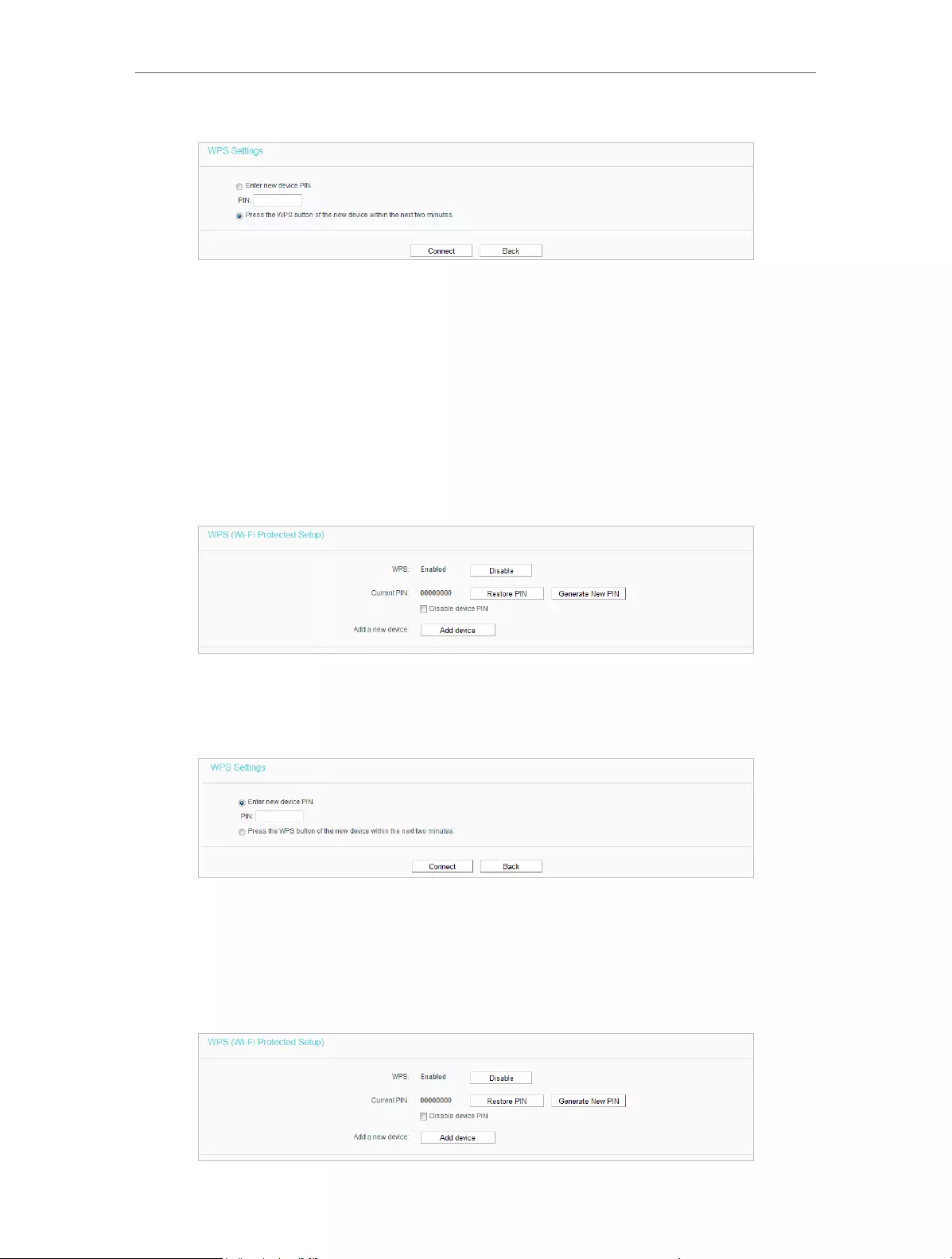
1. Keep the WPS Status as Enabled and click Add Device.
2. Select Press the WPS button of the new device in two minutes and click Connect.
25
Chapter 4 Congure the Router
3. Within two minutes, press the WPS button on your client device.
4. A success message will appear on the WPS page if the client device has been
successfully added to the router’s network.
Method TWO: Enter the Client’s PIN
1. Keep the WPS Status as Enabled and click Add Device.
2. Select Enter the new device’s PIN, enter your client device’s current PIN in the PIN
filed and click Connect.
3. A success message will appear on the WPS page if the client device has been
successfully added to the router’s network.
Method Three: Enter the Router’s PIN
1. Keep the WPS Status as Enabled and get the Current PIN of the router.

26
Chapter 4 Congure the Router
2. Enter the router’s current PIN on your client device to join the router’s Wi-Fi network.
4. 3. 3. Wireless Security
1. Visit http://tplinkwifi.net, and log in with the username and password you set for the
router.
2. Go to Wireless > Wireless Security.
3. Configure the the security settings of your wireless network and click Save.
• Disable Wireless Security — The wireless security function can be enabled or disabled.
If disabled, wireless clients can connect to the router without a password. It’s strongly
recommended to choose one of the following modes to enable security.
• WPA-PSK/WPA2-Personal — It’s the WPA/WPA2 authentication type based on pre-
shared passphrase.
• Authentication Type — Select Automatic, WPA-PSK or WPA2-PSK.
• Encryption — Select Automatic, TKIP or AES.
• Wireless Password — Enter ASCII or Hexadecimal characters. For Hexadecimal,
the length should be between 8 and 64 characters; for ASCII, the length should
be between 8 and 63 characters.
• Group Key Update Period — Specify the group key update interval in seconds.
The value can be 0 or at least 30. Enter 0 to disable the update.

27
Chapter 4 Congure the Router
• WPA /WPA2-Enterprise — It’s based on Radius Server.
• Authentication Type — Select Automatic, WPA or WPA2.
• Encryption — Select Automatic, TKIP or AES.
• Radius Server IP — Enter the IP address of the Radius server.
• Radius Port — Enter the port that Radius server used.
• Radius Password — Enter the password for the Radius server.
• Group Key Update Period — Specify the group key update interval in seconds.
The value should be 30 or above. Enter 0 to disable the update.
• WEP — It is based on the IEEE 802.11 standard.
• Authentication Type — The default setting is Automatic, which can select Shared
Key or Open System authentication type automatically based on the wireless
client’s capability and request.
• WEP Key Format — Hexadecimal and ASCII formats are provided here.
Hexadecimal format stands for any combination of hexadecimal digits (0-9,
a-f, A-F) in the specified length. ASCII format stands for any combination of
keyboard characters in the specified length.
• WEP Key (Password) — Select which of the four keys will be used and enter the
matching WEP key. Make sure these values are identical on all wireless clients
in your network.
• Key Type — Select the WEP key length (64-bit, 128-bit or 152-bit) for encryption.
Disabled means this WEP key entry is invalid.
• 64-bit — Enter 10 hexadecimal digits (any combination of 0-9, a-f and A-F. Null
key is not permitted) or 5 ASCII characters.
• 128-bit — Enter 26 hexadecimal digits (any combination of 0-9, a-f and A-F. Null
key is not permitted) or 13 ASCII characters.
• 152-bit — Enter 32 hexadecimal digits (any combination of 0-9, a-f and A-F. Null
key is not permitted) or 16 ASCII characters.
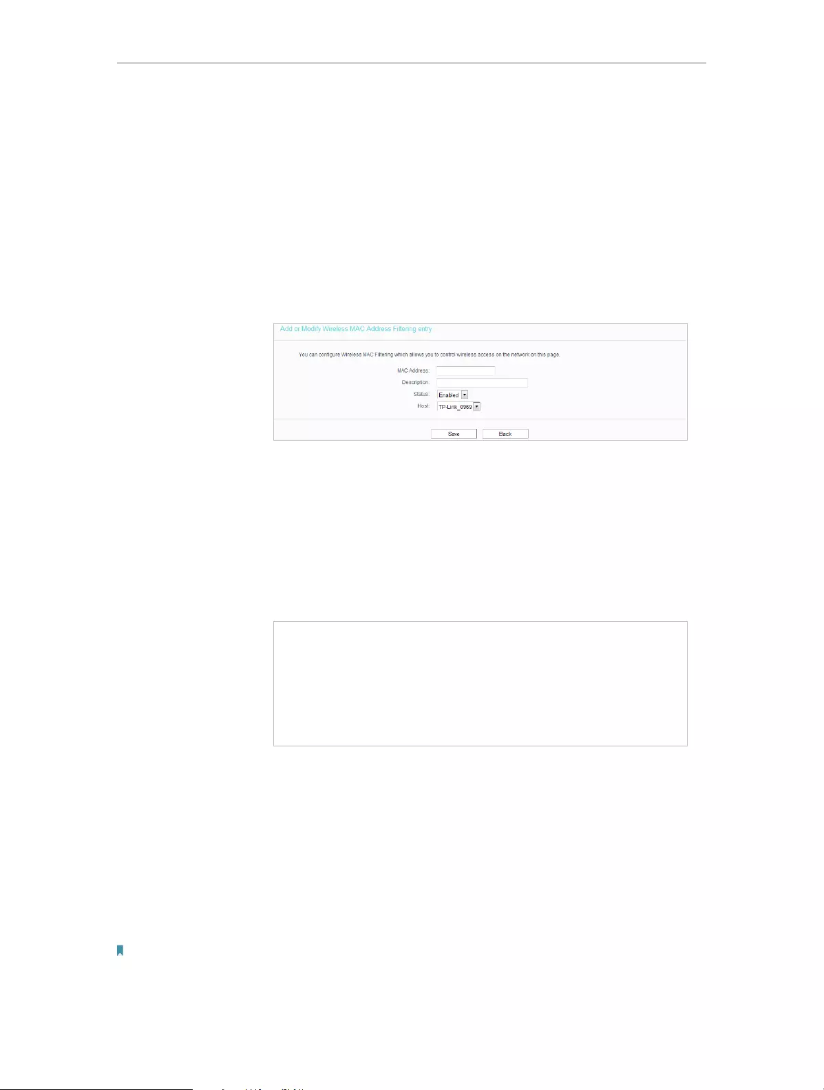
4. 3. 4. Wireless MAC Filtering
Wireless MAC Filtering is used to deny or allow specific wireless client devices to access
your network by their MAC addresses.
Deny or allow specific wireless client devices to access my
network by their MAC addresses.
For example, you want the wireless client A with the MAC
address 00-0A-EB-B0-00-0B and the wireless client B with the
MAC address 00-0A-EB-00-07-5F to access the router, but
other wireless clients cannot access the router.
I want to:
28
Chapter 4 Congure the Router
1. Visit http://tplinkwifi.net, and log in with the username and
password you set for the router.
2. Go to Wireless > Wireless MAC Filtering.
3. Click Enable to enable the Wireless MAC Filtering function.
4. Select Allow the stations specified by any enabled entries in
the list to access as the filtering rule.
5. Delete or disable all entries if there are any entries already.
6. Click Add New and fill in the blanks.
1 ) Enter the MAC address 00-0A-EB-B0-00-0B/00-0A-EB-
00-07-5F in the MAC Address field.
2 ) Enter wireless client A/B in the Description field.
3 ) Leave the status as Enabled.
4 ) Click Save and click Back.
7. The configured filtering rules should be listed as the picture
shows below.
Now only client A and client B can access your network.
4. 3. 5. Wireless Advanced
1. Visit http://tplinkwifi.net, and log in with the username and password you set for the
router.
2. Go to Wireless > Wireless Advanced.
3. Configure the advanced settings of your wireless network and click Save.
Note:
• If you are not familiar with the setting items on this page, it’s strongly recommended to keep the provided
default values; otherwise it may result in lower wireless network performance.
How can I
do that?
Done!

29
Chapter 4 Congure the Router
• Transmit Power — Select High, Middle or Low which you would like to specify for the
router. High is the default setting and recommended.
• Beacon Interval — Enter a value between 40-1000 milliseconds for Beacon Interval
here. Beacon Interval value determines the time interval of the beacons. The beacons
are the packets sent by the router to synchronize a wireless network. The default
value is 100.
• RTS Threshold — Here you can specify the RTS (Request to Send) Threshold. If the
packet is larger than the specified RTS Threshold size, the router will send RTS frames
to a particular receiving station and negotiate the sending of a data frame. The default
value is 2346.
• Fragmentation Threshold — This value is the maximum size determining whether
packets will be fragmented. Setting a low value for the Fragmentation Threshold may
result in poor network performance because of excessive packets. 2346 is the default
setting and is recommended.
• DTIM Interval — This value determines the interval of the Delivery Traffic Indication
Message (DTIM). A DTIM field is a countdown field informing clients of the next window
for listening to broadcast and multicast messages. When the router has buffered
broadcast or multicast messages for associated clients, it sends the next DTIM with
a DTIM Interval value. You can specify the value between 1-255 Beacon Intervals. The
default value is 1, which indicates the DTIM Interval is the same as Beacon Interval.
• Enable WMM — WMM function can guarantee the packets with high-priority messages
being transmitted preferentially. It is strongly recommended to enable this function.
• Enable Short GI — It is recommended to enable this function, for it will increase the
data capacity by reducing the guard interval time.
• Enable AP Isolation — This function isolates all connected wireless stations so that
wireless stations cannot access each other through WLAN. This function will be
disabled if WDS / Bridge is enabled.

30
Chapter 4 Congure the Router
4. 3. 6. Wireless Statistics
1. Visit http://tplinkwifi.net, and log in with the username and password you set for the
router.
2. Go to Wireless > Wireless Statistics to check the data packets sent and received by
each client device connected to the router.
• MAC Address — The MAC address of the connected wireless client.
• Current Status — The running status of the connected wireless client.
• Received Packets — Packets received by the wireless client.
• Sent Packets — Packets sent by the wireless client.
• SSID — SSID that the station associates with.
4. 4. Guest Network
Guest Network allows you to provide Wi-Fi access for guests without disclosing your
host network. When you have guests in your house, apartment, or workplace, you
can create a guest network for them. In addition, you can customize guest network
permissions to ensure network security and privacy.
If you run a small shop, you can set up Facebook Wi-Fi. It allows customers to easily
connect to your Wi-Fi by redirecting them to your company’s Facebook page. Here, they
are encouraged to check in and like your page before receiving free web access. This
raises the profile of your business on Facebook and increases customer engagement
with promotional content on your page.
1. Visit http://tplinkwifi.net, and log in with the username and password you set for the
router.
2. Go to Guest Network.

31
Chapter 4 Congure the Router
3. Enable the Guset Network function.
4. Create a network name for your guest network.
5. Configure the Security type.
• To configure a secure network, select WPA/WPA2 — Personal and create a
password for the guest network.
6. Select Schedule from the Access Time drop-down list and customize it for the
guest network.
7. Customize guest network permissions.
• Allow Guest To Access My Local Network — If enabled, guests can access the
local network and manage it.
• Guest Network Isolation — If enabled, guests are isolated from each other.
• Enable Guest Network Bandwidth Control — If enabled, the Guest Network
Bandwidth Control rules will take effect.
32
Chapter 4 Congure the Router
Note:
The range of bandwidth for guest network is calculated according to the setting of Bandwidth Control on the
Bandwidth Control > Control Settings page.
8. Click Save.
4. 5. DHCP
By default, the DHCP (Dynamic Host Configuration Protocol) Server is enabled and the
router acts as a DHCP server; it dynamically assigns TCP/IP parameters to client devices
from the IP Address Pool. You can change the settings of DHCP Server if necessary,
and you can reserve LAN IP addresses for specified client devices.
4. 5. 1. DHCP Settings
1. Visit http://tplinkwifi.net, and log in with the username and password you set for the
router.
2. Go to DHCP > DHCP Settings.
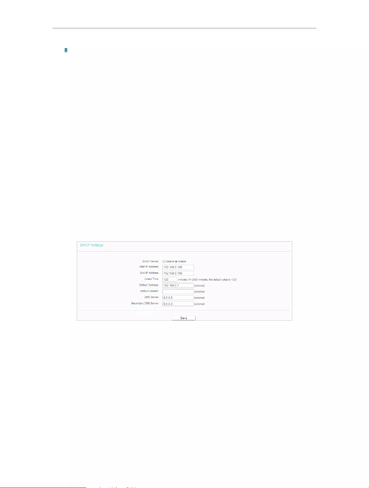
3. Specify DHCP server settings and click Save.
• DHCP Server — Enable or disable the DHCP server. If disabled, you must have another
DHCP server within your network or else you must configure the computer manually.
• Start IP Address — Specify an IP address for the DHCP Server to start with when
assigning IP addresses.
• End IP Address — Specify an IP address for the DHCP Server to end with when assigning
IP addresses.
• Lease Time — The Address Lease Time is the amount of time a network user will be
allowed to connect to the router with the current dynamic IP Address. When time is
up, the user will be automatically assigned a new dynamic IP address.
• Default Gateway (Optional) — It is suggested to input the IP address of the LAN port of
the router.
33
Chapter 4 Congure the Router
• Default Domain (Optional) — Input the domain name of your network.
• DNS Server (Optional) — Input the DNS IP address provided by your ISP.
• Secondary DNS Server (Optional) — Input the IP address of another DNS server if your
ISP provides two DNS servers.
Note:
To use the DHCP server function of the router, you must configure all computers on the LAN as Obtain an IP Address
automatically.
4. 5. 2. DHCP Client List
1. Visit http://tplinkwifi.net, and log in with the username and password you set for the
router.
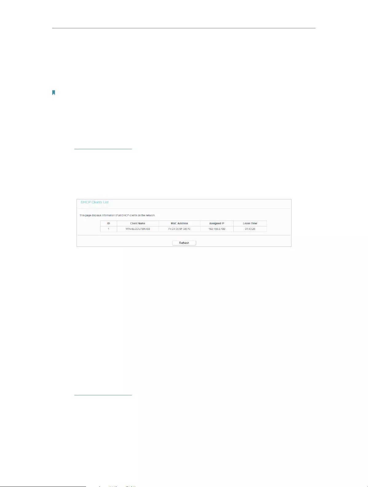
2. Go to DHCP > DHCP Client List to view the information of the clients connected to
the router.
• Client Name — The name of the DHCP client.
• MAC Address — The MAC address of the DHCP client.
• Assigned IP — The IP address that the outer has allocated to the DHCP client.
• Lease Time — The time of the DHCP client leased. After the dynamic IP address has
expired, a new dynamic IP address will be automatically assigned to the user.
You cannot change any of the values on this page. To update this page and show the
current attached devices, click Refresh.
4. 5. 3. Address Reservation
You can reserve an IP address for a specific client. When you specify a reserved IP
address for a PC on the LAN, this PC will always receive the same IP address each time
when it accesses the DHCP server.
1. Visit http://tplinkwifi.net, and log in with the username and password you set for the
router.
2. Go to DHCP > Address Reservation.
3. Click Add New and fill in the blank.

34
Chapter 4 Congure the Router
1 ) Enter the MAC address (in XX—XX—XX—XX—XX—XX format.) of the client for which
you want to reserve an IP address.
2 ) Enter the IP address (in dotted—decimal notation) which you want to reserve for
the client.
3 ) Leave the Status as Enabled.
4 ) Click Save.
4. 6. Forwarding
The router’s NAT (Network Address Translation) feature makes the devices on the LAN
use the same public IP address to communicate in the internet, which protects the
local network by hiding IP addresses of the devices. However, it also brings about the
problem that external hosts cannot initiatively communicate with the specified devices
in the local network.
With the forwarding feature, the router can traverse the isolation of NAT so that clients
on the internet can reach devices on the LAN and realize some specific functions.
The TP-Link router includes four forwarding rules. If two or more rules are set, the
priority of implementation from high to low is Virtual Servers, Port Triggering, UPNP and
DMZ.
4. 6. 1. Virtual Server
When you build up a server in the local network and want to share it on the internet,
Virtual Servers can realize the service and provide it to internet users. At the same time
virtual servers can keep the local network safe as other services are still invisible from
the internet.
Virtual Servers can be used to set up public services in your local network, such as
HTTP, FTP, DNS, POP3/SMTP and Telnet. Different service uses different service port.
Port 80 is used in HTTP service, port 21 in FTP service, port 25 in SMTP service and port
110 in POP3 service. Please verify the service port number before the configuration.
Share my personal website I’ve built in local network with my
friends through the internet.
I want to:

35
Chapter 4 Congure the Router
For example, the personal website has been built in my home PC
(192.168.0.100). I hope that my friends on the Internet can visit
my website in some way. My PC is connected to the router with
the WAN IP address 218.18.232.154.
Router
WAN: 218.18.232.154
LAN
Home
Personal Website
1. Set your PC to a static IP address, for example 192.168.0.100.
2. Visit http://tplinkwifi.net, and log in with the username and
password you set for the router.
3. Go to Forwarding > Virtual Servers.
4. Click Add New. Select HTTP from the Common Service
Port list. The service port, internal port and protocol
will be automatically filled in. Enter the PC’s IP address
192.168.0.100 in the IP Address field.
5. Leave the status as Enabled and click Save.
Note:
• It is recommended to keep the default settings of Internal Port and
Protocol if you are not clear about which port and protocol to use.
• If the service you want to use is not in the Common Service Port list, you
can enter the corresponding parameters manually. You should verify the
port number that the service needs.
• You can add multiple virtual server rules if you want to provide several
services in a router. Please note that the Service Port should not be
overlapped.
Users on the Internet can enter http:// WAN IP (in this example:
http:// 218.18.232.154) to visit your personal website.
Note:
• If you have changed the default Service Port, you should use http:// WAN
IP: Service Port to visit the website.
Done!

36
Chapter 4 Congure the Router
• Some specific service ports are forbidden by the ISP, if you fail to visit the
website, please use another service port.
4. 6. 2. Port Triggering
Port triggering can specify a triggering port and its corresponding external ports. When
a host in the local network initiates a connection to the triggering port, all the external
ports will be opened for subsequent connections. The router can record the IP address
of the host. When the data from the Internet return to the external ports, the router
can forward them to the corresponding host. Port triggering is mainly applied to online
games, VoIPs, video players and common applications including MSN Gaming Zone,
Dialpad, Quick Time 4 players and more.
Follow the steps below to configure the port triggering rules:
1. Visit http://tplinkwifi.net, and log in with the username and password you set for the
router.
2. Go to Forwarding > Port Triggering.
3. Click Add New. Select the desired application from the Common Applications list. The
trigger port amd incoming ports will be automatically filled in. The following picture
takes application MSN Gaming Zone as an example.
4. Leave the status as Enabled and click Save.
Note:
• You can add multiple port triggering rules as needed.
• The triggering ports can not be overlapped.
• If the application you need is not listed in the Common Applications list, please enter the parameters
manually. You should verify the incoming ports the application uses first and enter them in Incoming
Ports field. You can input at most 5 groups of ports (or port sections). Every group of ports must be set
apart with “,”. For example, 2000-2038, 2050-2051, 2085, 3010-3030.
4. 6. 3. DMZ
When a PC is set to be a DMZ (Demilitarized Zone) host in the local network, it is totally
exposed to the Internet, which can realize the unlimited bidirectional communication

37
Chapter 4 Congure the Router
between internal hosts and external hosts. The DMZ host becomes a virtual server with
all ports opened. When you are not clear about which ports to open in some special
applications, such as IP camera and database software, you can set the PC to be a DMZ
host.
Note:
DMZ is more applicable in the situation that users are not clear about which ports to open. When it is enabled, the DMZ
host is totally exposed to the Internet, which may bring some potential safety hazards. If DMZ is not in use, please disable
it in time.
Make the home PC join the Internet online game without port
restriction.
For example, due to some port restriction, when playing the
online games, you can log in normally but cannot join a team
with other players. To solve this problem, set your PC as a DMZ
host with all ports opened.
1. Assign a static IP address to your PC, for example
192.168.0.100.
2. Visit http://tplinkwifi.net, and log in with the username and
password you set for the router.
3. Go to Forwarding > DMZ.
4. Select Enable and enter the IP address 192.168.0.100 in the
DMZ Host IP Address filed.
5. Click Save.
You’ve set your PC to a DMZ host and now you can make a team
to game with other players.
4. 6. 4. UPnP
The UPnP (Universal Plug and Play) protocol allows the applications or host devices
to automatically find the front—end NAT device and send request to it to open the
corresponding ports. With UPnP enabled, the applications or host devices on the
local network and the Internet can freely communicate with each other realizing the
seamless connection of the network. You may need to enable the UPnP if you want
to use applications for multiplayer gaming, peer-to-peer connections, real-time
communication (such as VoIP or telephone conference) or remote assistance, etc.
I want to:
How can I
do that?
Done!

38
Chapter 4 Congure the Router
Tips:
• UPnP is enabled by default in this router.
• Only the application supporting UPnP protocol can use this feature.
• UPnP feature needs the support of operating system (e.g. Windows Vista/ Windows 7/ Windows 8, etc.
Some of operating system need to install the UPnP components).
For example, when you connect your Xbox to the router which is connected to the Internet
to play online games, UPnP will send request to the router to open the corresponding
ports allowing the following data penetrating the NAT to transmit. Therefore, you can
play Xbox online games without a hitch.
RouterXbox
LAN WAN
If necessary, you can follow the steps to change the status of UPnP.
1. Visit http://tplinkwifi.net, and log in with the username and password you set for the
router.
2. Go to Forwarding > UPnP.
3. Click Disable or Enable according to your needs.
4. 7. Security
This function allows you to protect your home network from cyber attacks and
unauthorized users by implementing these network security functions.
4. 7. 1. Basic Security
1. Visit http://tplinkwifi.net, and log in with the username and password you set for the
router.
2. Go to Security > Basic Security, and you can enable or disable the security functions.

39
Chapter 4 Congure the Router
• Firewall — A firewall protects your network from Internet attacks.
• SPI Firewall — SPI (Stateful Packet Inspection, also known as dynamic packet
filtering) helps to prevent cyber attacks by tracking more state per session. It
validates that the traffic passing through the session conforms to the protocol.
SPI Firewall is enabled by default.
• VPN — VPN Passthrough must be enabled if you want to allow VPN tunnels using IPSec,
PPTP or L2TP protocols to pass through the router’s firewall.
• PPTP Passthrough — Point-to-Point Tunneling Protocol (PPTP) allows the Point-
to-Point Protocol (PPP) to be tunneled through an IP network. If you want to allow
PPTP tunnels to pass through the router, you can keep the default (Enabled).
• L2TP Passthrough — Layer 2 Tunneling Protocol (L2TP) is the method used
to enable Point-to-Point sessions via the Internet on the Layer 2 level. If you
want to allow L2TP tunnels to pass through the router, you can keep the default
(Enabled).
• IPSec Passthrough — Internet Protocol Security (IPSec) is a suite of protocols for
ensuring private, secure communications over Internet Protocol (IP) networks,
through the use of cryptographic security services. If you want to allow IPSec
tunnels to pass through the router, you can keep the default (Enabled).
• ALG — It is recommended to enable Application Layer Gateway (ALG) because ALG
allows customized Network Address Translation (NAT) traversal filters to be plugged
into the gateway to support address and port translation for certain application layer
“control/data” protocols such as FTP, TFTP, H323 etc.

40
Chapter 4 Congure the Router
• FTP ALG — To allow FTP clients and servers to transfer data across NAT, keep
the default Enable.
• TFTP ALG — To allow TFTP clients and servers to transfer data across NAT, keep
the default Enable.
• H323 ALG — To allow Microsoft NetMeeting clients to communicate across NAT,
keep the default Enable.
• RTSP ALG — To allow some media player clients to communicate with some
streaming media servers across NAT, click Enable.
• SIP ALG — To allow some multimedia clients to communicate across NAT, click
Enable.
3. Click Save.
4. 7. 2. Advanced Security
1. Visit http://tplinkwifi.net, and log in with the username and password you set for the
router.
2. Go to Security > Advanced Security, and you can protect the router from being
attacked by ICMP-Flood, UDP Flood and TCP-SYN Flood.
• DoS Protection — Denial of Service protection. Select Enable or Disable to enable or
disable the DoS protection function. Only when it is enabled, will the flood filters be
enabled.
Note:
Dos Protection will take effect only when the Statistics in System Tool > Statistics is enabled.
• Enable ICMP-FLOOD Attack Filtering -Check the box to enable or disable this function.
• ICMP-FLOOD Packets Threshold (5~3600) — The default value is 50. Enter a value
between 5 ~ 3600. When the number of the current ICMP-FLOOD packets is beyond
the set value, the router will startup the blocking function immediately.
• Enable UDP-FLOOD Filtering — Check the box to enable or disable this function.

41
Chapter 4 Congure the Router
• UDP-FLOOD Packets Threshold (5~3600) — The default value is 500. Enter a value
between 5 ~ 3600. When the number of the current UPD-FLOOD packets is beyond
the set value, the router will startup the blocking function immediately.
• Enable TCP-SYN-FLOOD Attack Filtering -Check the box to enable or disable this
function.
• TCP-SYN-FLOOD Packets Threshold (5~3600) — The default value is 50. Enter a value
between 5 ~ 3600. When the number of the current TCP-SYN-FLOOD packets is
beyond the set value, the router will startup the blocking function immediately.
• Forbid Ping Packet From WAN Port — Enable or Disable Forbid Ping Packet From WAN
Port. The default setting is enabled. The ping packet from WAN cannot access the
Router. (Defends against some viruses).
• Forbid Ping Packet From LAN Port — The default setting is disabled. If enabled, the
ping packet from LAN cannot access the router. This function can be used to defend
against some viruses.
3. Click Save.
4. Click Blocked DoS Host List to display the DoS host table by blocking.
4. 7. 3. Local Management
1. Visit http://tplinkwifi.net, and log in with the username and password you set for the
router.
2. Go to Security > Local Management, and you can block computers in LAN from
accessing the router.
For example, if you want to allow PCs with specific MAC addresses to access the router’s
web management page locally from inside the network, please follow the instructions
below:
1 ) Select Only the PCs listed can browse the built-in web pages to perform
Administrator tasks.
2 ) Enter the MAC address of each PC separately. The format of the MAC address
is XX—XX—XX—XX—XX—XX (X is any hexadecimal digit). Only the PCs with the listed

42
Chapter 4 Congure the Router
MAC addresses can use the password to browse the built-in web pages to
perform administrator tasks.
3 ) Click Add, and your PC’s MAC address will also be listed.
4 ) Click Save.
Note:
If your PC is blocked but you want to access the router again, press and hold the Reset button to reset the router to the
factory defaults.
4. 7. 4. Remote Management
1. Visit http://tplinkwifi.net, and log in with the username and password you set for the
router.
2. Go to Security > Remote Management, and you can manage your router from a
remote device via the Internet.
• Web Management Port — Web browser access normally uses the standard HTTP
service port 80. This router’s default remote management web port number is 80.
For higher security, you can change the remote management web port to a custom
port by entering a number between 1 and 65534 but do not use the number of any
common service port.
• Remote Management IP Address — This is the address you will use when accessing
your router via a remote device. This function is disabled when the IP address is set
to the default value of 0.0.0.0. To enable this function, change 0.0.0.0 to a valid IP
address. If it is set to 255.255.255.255, then all the remote devices can access the
router from the Internet.
Note:
• To access the router, enter your router’s WAN IP address in your browser’s address bar, followed by a
colon and the custom port number. For example, if your router’s WAN address is 202.96.12.8, and the
port number used is 8080, please enter http://202.96.12.8:8080 in your browser. Later, you may be asked
for the router’s password. After successfully entering the username and password, you will be able to
access the router’s web management page.
• Be sure to change the router’s default password for security purposes.

43
Chapter 4 Congure the Router
4. 8. Parental Controls
Parental Controls allows you to block inappropriate and malicious websites, and control
access to specific websites at specific time for your children’s devices.
For example, you want the children’s PC with the MAC address 00-11-22-33-44-AA can
access www.tp-link.com on Saturday only while the parent PC with the MAC address
00-11-22-33-44-BB is without any restriction.
1. Visit http://tplinkwifi.net, and log in with the username and password you set for the
router.
2. Go to Parental Controls.
3. Check the Enable Parental Controls box and enter the MAC address 00:11:22:33:44:BB
in the MAC Address of Parental PC field.
4. Enter 00:11:22:33:44:AA in the MAC Address 1 field.
5. Create a new schedule with Day is Sat and Time is all day-24 hours. Click Add
6. Enter www.tp-link.com in the Add URL field. Click Add.
7. Click Save.
Then you will see the page as shown in figure below.
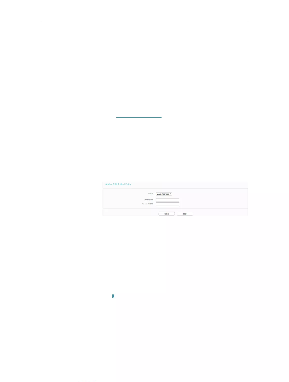
44
Chapter 4 Congure the Router
4. 9. Access Control
Access Control is used to deny or allow specific client devices to access your network
with access time and content restrictions.
Deny or allow specific client devices to access my network with
access tiem and content restrictions.
For example, If you want to restrict the internet activities of host
with MAC address 00-11-22-33-44-AA on the LAN to access
www.tp-link.com only, please follow the steps below:
1. Visit http://tplinkwifi.net, and log in with the username and
password you set for the router.
2. Go to Access Control > Host and configure the host settings:
1 ) Click Add New.
2 ) Select MAC Address as the mode type. Create a unique
description (e.g. host_1) for the host in the Description
field and enter 00-11-22-33-44-AA in the MAC Address
filed.
3 ) Click Save.
3. Go to Access Control > Target and configure the target
settings:
1 ) Click Add New.
2 ) Select URL Address as the mode type. Create a unique
description (e.g. target_1) for the target in the Target
Description field and enter the domain name, either the
full name or the keywords (for example TP-Link) in the
Add URL Address field.
Note:
Any URL address with keywords in it (e.g. www.tp-link.com) will be
blocked or allowed.
I want to:
How
can I do
that?

45
Chapter 4 Congure the Router
3 ) Click Save.
4. Go to Access Control > Schedule and configure the schedule
settings:
1 ) Click Add New.
2 ) Create a unique description (e.g. schedule_1) for the
schedule in the Schedule Description field and set the
day(s) and time period.
3 ) Click Save.
5. Go to Access Control > Rule and add a new access control
rule.
1 ) Click Add New.
2 ) Give a name for the rule in the Description field. Select
host_1 from the LAN host drop—down list; select target_1
from the target drop-down list; select schedule_1 from
the schedule drop—down list.

46
Chapter 4 Congure the Router
3 ) Leave the status as Enabled as click Save.
6. Select Enable Internet Access Control to enable Access
Control function.
7. Select Allow the packets specified by any enabled access
control policy to pass through the Router as the default filter
policy and click Save.
Now only the specific host(s) can visit the target(s) within the
scheduled time period.
4. 10. Advanced Routing
Static Routing is a form of routing that is configured manually by a network administrator
or a user by adding entries into a routing table. The manually-configured routing
information guides the router in forwarding data packets to the specific destination.
4. 10. 1. Static Route List
1. Visit http://tplinkwifi.net, and log in with the username and password you set for the
router.
2. Go to Advanced Routing > Static Route List.
¾To add static routing entries:
1. Click Add New.
Done!
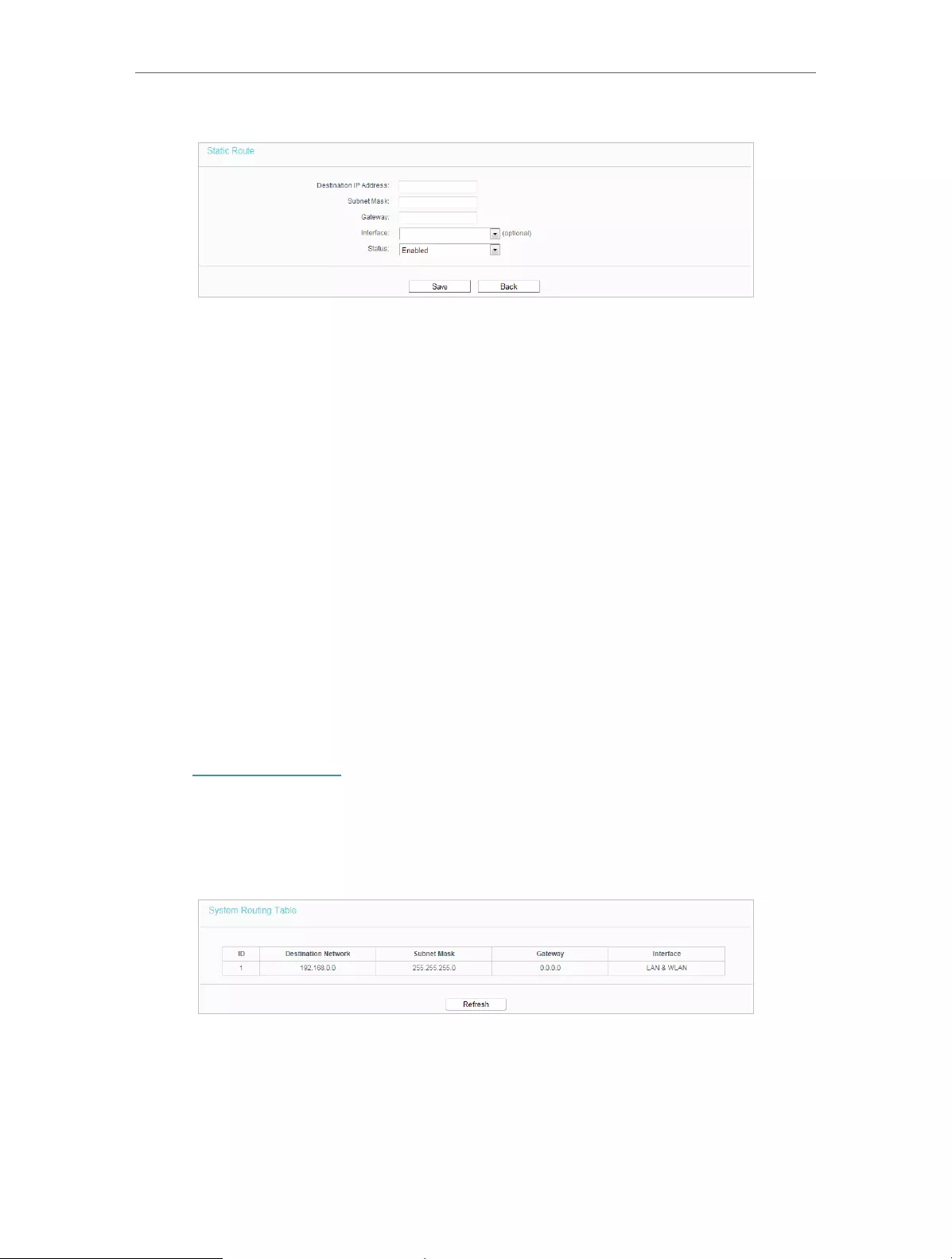
47
Chapter 4 Congure the Router
2. Enter the following information.
• Destination IP Address — The Destination Network is the address of the network
or host that you want to assign to a static route.
• Subnet Mask — The Subnet Mask determines which portion of an IP address is
the network portion, and which portion is the host portion.
• Gateway — This is the IP address of the default gateway device that allows the
contact between the router and the network or host.
3. Select Enabled or Disabled for this entry on the Status drop-down list.
4. Click Save.
You can also do the following operations to modify the current settings.
• Click the Enable Selected button to enable selected entries..
• Click the Disable Selected button to disable selected entries.
• Click the Delete Selected button to delete selected entries.
4. 10. 2. System Routing Table
1. Visit http://tplinkwifi.net, and log in with the username and password you set for the
router.
2. Go to Advanced Routing > System Routing Table, and you can view all the valid route
entries in use.
• Destination Network — The Destination Network is the address of the network or host
to which the static route is assigned.
• Subnet Mask — The Subnet Mask determines which portion of an IP address is the
network portion, and which portion is the host portion.
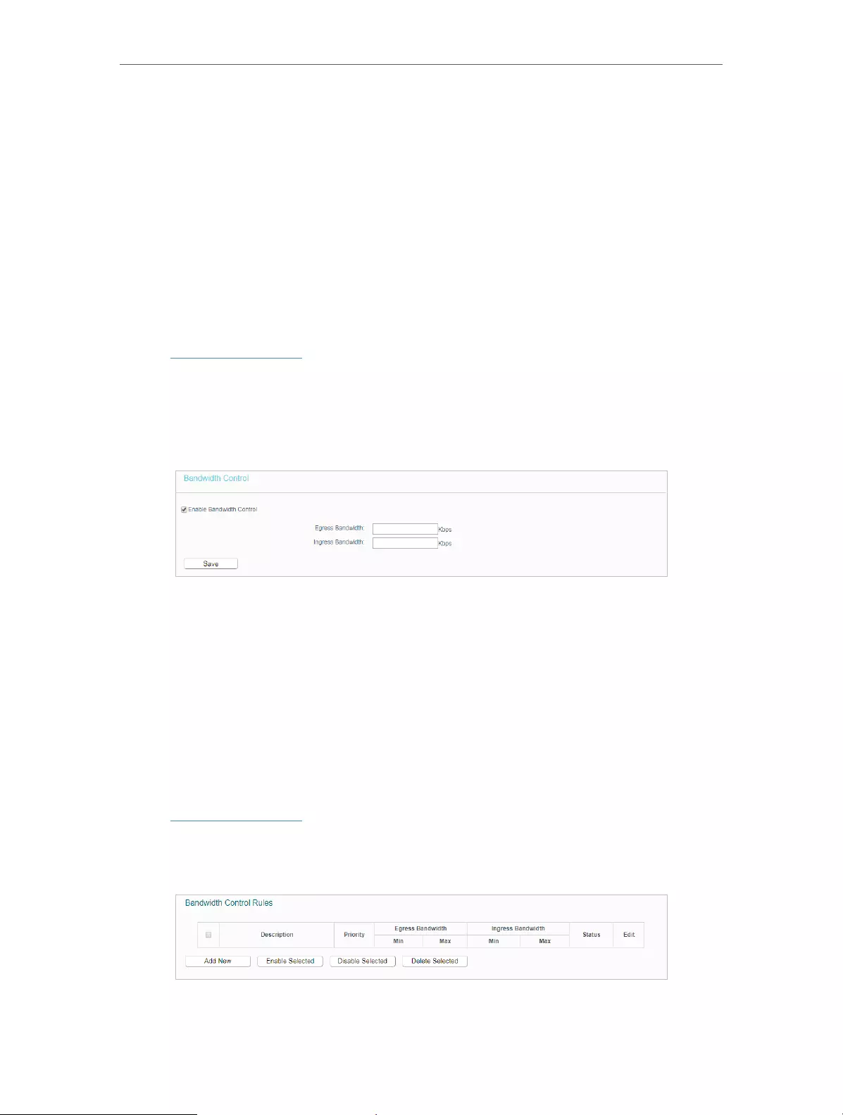
48
Chapter 4 Congure the Router
• Gateway — This is the IP address of the gateway device that allows for contact between
the Router and the network or host.
• Interface — This interface tells you whether the Destination IP Address is on the LAN &
WLAN (internal wired and wireless networks), or the WAN (Internet).
• Click Refresh to refresh the data displayed.
4. 11. Bandwidth Control
4. 11. 1. Control Settings
1. Visit http://tplinkwifi.net, and log in with the username and password you set for the
router.
2. Go to Bandwidth Control.
3. Configure the bandwidth as needed and click Save.
The values you configure for the Egress Bandwidth and Ingress Bandwidth should be
less than 100,000Kbps. For optimal control of the bandwidth, please select the right
Line Type and consult your ISP for the total egress and ingress bandwidth.
• Enable Bandwidth Control — Check this box so that the Bandwidth Control settings
can take effect.
• Egress Bandwidth — The upload speed through the WAN port.
• Ingress Bandwidth — The download speed through the WAN port.
4. 11. 2. Rule List
1. Visit http://tplinkwifi.net, and log in with the username and password you set for the
router.
2. Go to Bandwidth Control and you can view and configure the Bandwidth Control rules.
• Description — This is the information about the rules such as address range.
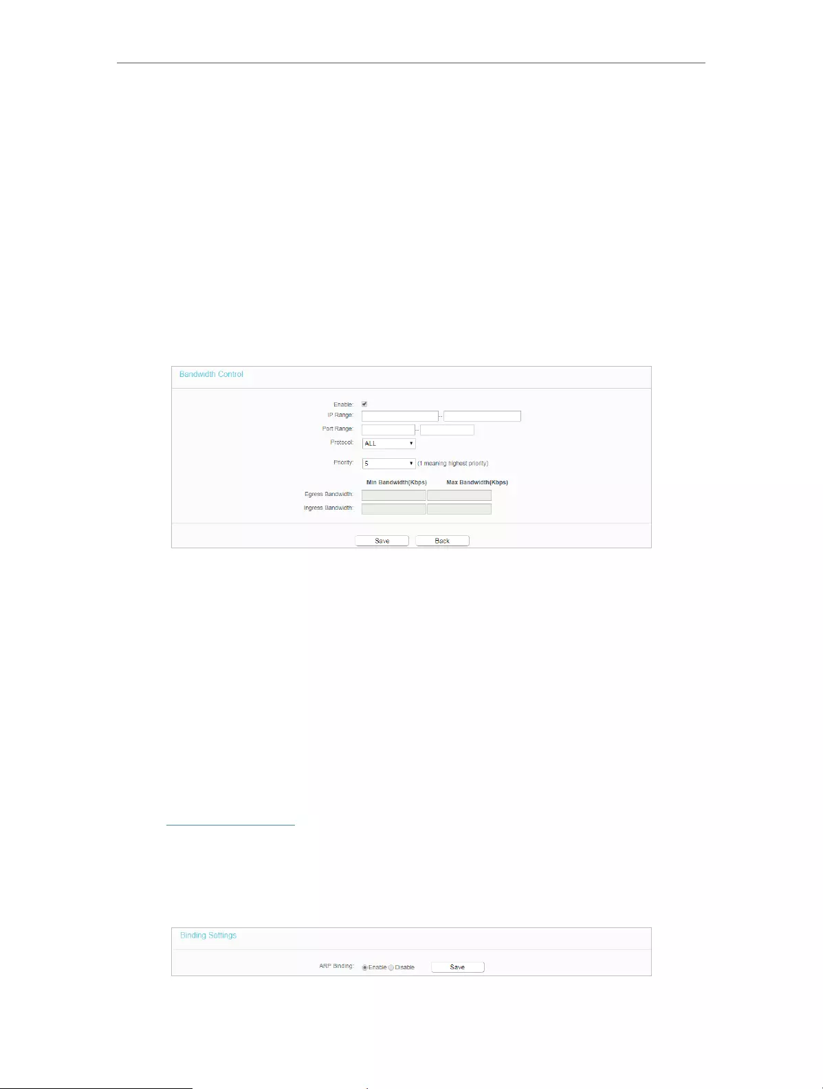
49
Chapter 4 Congure the Router
• Egress Bandwidth — This field displays the max and min upload bandwidth through the
WAN port. The default is 0.
• Ingress Bandwidth — This field displays the max and min download bandwidth through
the WAN port. The default is 0.
• Status — This field displays the status of the rule.
• Modify — Click Modify/Delete to edit/delete the rule.
¾To add a Bandwidth control rule:
1. Click Add New.
2. Enter the information as the figure shown below.
3. Click Save.
4. 12. IP & MAC Binding
IP & MAC Binding, namely, ARP (Address Resolution Protocol) Binding, is used to bind
a network device’s IP address to its MAC address. This will prevent ARP spoofing and
other ARP attacks by denying network access to a device with a matching IP address in
the ARP list, but with an unrecognized MAC address.
4. 12. 1. Binding Settings
1. Visit http://tplinkwifi.net, and log in with the username and password you set for the
router.
2. Go to IP & MAC Binding > Binding Settings.
3. Select Enable for ARP Binding.
4. Click Save.
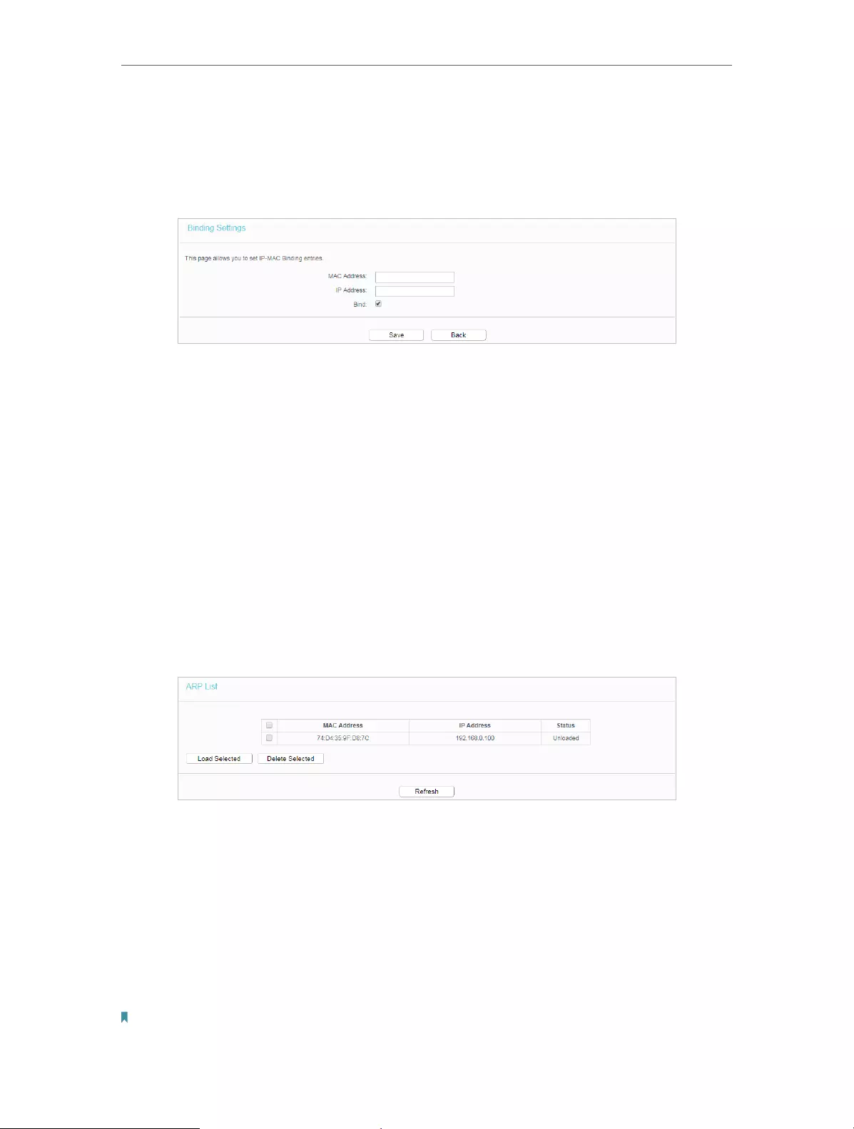
50
Chapter 4 Congure the Router
¾To add IP & MAC Binding entries:
1. Click Add New.
2. Select the Bind checkbox.
3. Enter the MAC address and IP address.
4. Click Save.
¾To modify or delete an existing entry:
1. Select the desired entry in the table.
2. Click Edit or Delete Selected.
4. 12. 2. ARP List
To manage a device, you can observe the device on the LAN by checking its MAC
address and IP address on the ARP list, and you can also configure the items. This page
displays the ARP list which shows all the existing IP & MAC Binding entries.
• MAC Address — The MAC address of the listed computer on the LAN.
• IP Address — The assigned IP address of the listed computer on the LAN.
• Status — Indicates whether or not the MAC and IP addresses are bound.
• Click the Load Selected button to load the selected items to the IP & MAC Binding list.
• Click the Delete Selected button to delete the selected items to the IP & MAC Binding
list.
• Click the Refresh button to refresh all items.
Note:

51
Chapter 4 Congure the Router
An item can not be loaded to the IP & MAC Binding list if the IP address of the item has been loaded before. Error warning
will prompt as well. Likewise, Load All only loads the items without interference to the IP & MAC Binding list.
4. 13. Dynamic DNS
The router offers the DDNS (Dynamic Domain Name System) feature, which allows the
hosting of a website, FTP server, or e-mail server with a fixed domain name (named by
yourself) and a dynamic IP address. Thus your friends can connect to your server by
entering your domain name no matter what your IP address is. Before using this feature,
you need to sign up for DDNS service providers such as www.comexe.cn,
www.dyndns.org, or www.noip.com. The Dynamic DNS client service provider will give
you a password or key.
1. Visit http://tplinkwifi.net, and log in with the username and password you set for the
router.
2. Go to Dynamic DNS.
Dyndns DDNS
If the dynamic DNS Service Provider you select is dyn.com/dns, the following page will
appear.
To set up for DDNS, follow these instructions:
1. Enter the User Name for your DDNS account.
2. Enter the Password for your DDNS account.
3. Enter the Domain Name you received from dynamic DNS service provider here.
4. Select Enable DDNS.
5. Click Login.
6. Click Save.
• Connection Status — The status of the DDNS service connection is displayed here.

52
Chapter 4 Congure the Router
• Logout — Click Logout to log out of the DDNS service.
No-ip DDNS
If the dynamic DNS Service Provider you select is www.noip.com, the following page
will appear.
To set up for DDNS, follow these instructions:
1. Enter the Domain Name you received from dynamic DNS service provider.
2. Enter the Username for your DDNS account.
3. Enter the Password for your DDNS account.
4. Click Login.
5. Click Save.
• Connection Status — The status of the DDNS service connection is displayed here.
• Logout — Click Logout to log out of the DDNS service.
Comexe DDNS
If the dynamic DNS Service Provider you select is www.comexe.cn, the following page
will appear.

53
Chapter 4 Congure the Router
To set up for DDNS, follow these instructions:
1. Enter the Domain Name received from your dynamic DNS service provider.
2. Enter the Username for your DDNS account.
3. Enter the Password for your DDNS account.
4. Click Login.
5. Click Save.
• Connection Status — The status of the DDNS service connection is displayed here.
• Logout — Click Logout to log out of the DDNS service.
4. 14. IPv6
This function allows you to enable IPv6 function and set up the parameters of the
router’s Wide Area Network (WAN) and Local Area Network (LAN).
4. 14. 1. IPv6 Status
1. Visit http://tplinkwifi.net, and log in with the username and password you set for the
router.
2. Go to IPv6 > IPv6 Status, and you can view the current IPv6 status information of
the router.
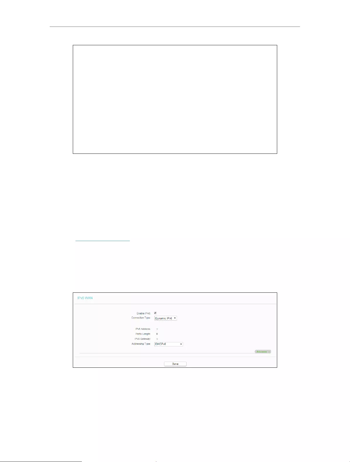
54
Chapter 4 Congure the Router
• WAN — This section shows the current IPv6 information of the router’s WAN port,
including Connection Type, IPv6 Address information, IPv6 Default Gateway, Primary
IPv6 DNS and Secondary IPv6 DNS.
• LAN — This section shows the current IPv6 information of the router’s LAN port,
including IPv6 Address Assign Type, IPv6 Address and Prefix Length.
4. 14. 2. IPv6 WAN
1. Visit http://tplinkwifi.net, and log in with the username and password you set for the
router.
2. Go to IPv6 > IPv6 WAN.
3. Eanble IPv6.
4. Select the WAN Connection Type according to your ISP network topolopy:
• Dynamic IPv6 — Connections which use dynamic IPv6 address assignment.
• Static IPv6 — Connections which use static IPv6 address assignment.
• PPPoEv6 — Connections which use PPPoEV6 that requires a username and
password.
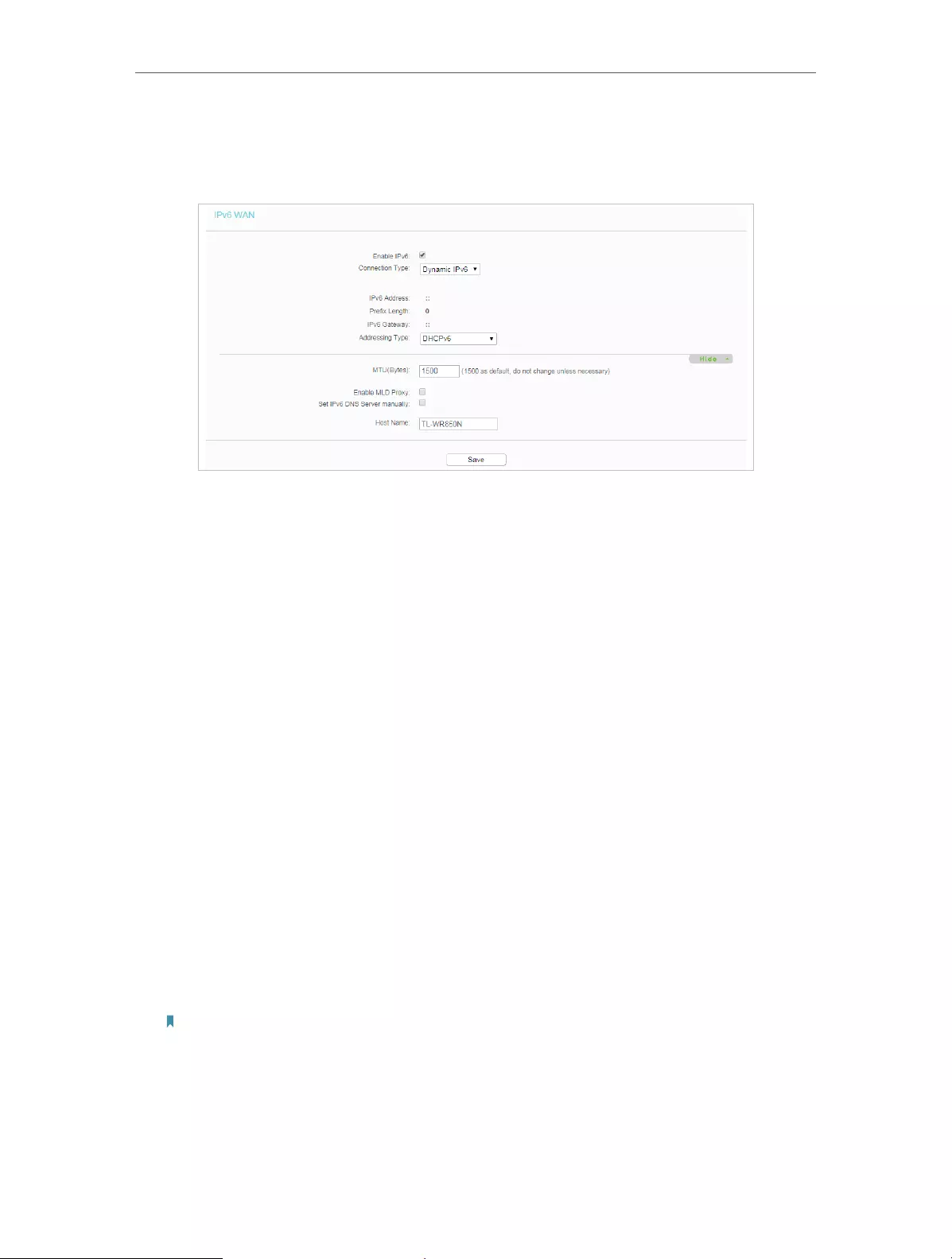
55
Chapter 4 Congure the Router
• Tunnel 6to4 — Connections which use 6to4 address assignment.
Dynamic IPv6
• IPv6 Address — The IPv6 address assigned by your ISP dynamically.
• Prefix Length — The length of IPv6 address prefix.
• IPv6 Gateway — Enter the default gateway provided by your ISP.
• Addressing Type — There are two types of assignation for IPv6 address:
SLAAC (Stateless address auto-configuration) and DHCPv6 (Dynamic Host
Configuration Protocol for IPv6) Server.
• MTU(Bytes) — The normal MTU (Maximum Transmission Unit) value for most
Ethernet networks is 1500 Bytes. For some ISPs, you may need to modify the
MTU. But this is rarely required, and should not be done unless you are sure it is
necessary for your ISP connection.
If your ISP gives you one or two DNS IPv6 addresses, select Set IPv6 DNS Server
manually and enter the IPv6 DNS Server and Secondary IPv6 DNS Server into the
correct fields. Otherwise, the DNS servers will be assigned from ISP dynamically.
• Enable MLD Proxy — Enable the Multicast Listener Discovery (MLD) Proxy
function if you need.
• Primary IPv6 DNS — Enter the DNS IPv6 address in colon-hexadecimal notation
provided by your ISP.
• Secondary IPv6 DNS — Enter another DNS IPv6 address in colon-hexadecimal
notation provided by your ISP.
Note:
If you get “Address not found error” when you access a web site, it is likely that your DNS servers are set up
improperly. You should contact your ISP to get DNS server addresses.

56
Chapter 4 Congure the Router
Static IPv6
• IPv6 Address — Enter the IPv6 address provided by your ISP.
• Prefix Length — The length of IPv6 address prefix.
• IPv6 Gateway — Enter the default gateway provided by your ISP.
• IPv6 DNS Server — Enter the DNS IPv6 address provided by your ISP.
• Secondary IPv6 DNS Server — Enter another DNS IPv6 address provided by
your ISP.
• MTU(Bytes) — The normal MTU (Maximum Transmission Unit) value for most
Ethernet networks is 1500 Bytes. For some ISPs, you may need to modify the
MTU. But this is rarely required, and should not be done unless you are sure it is
necessary for your ISP connection.
• Enable MLD Proxy — Enable the Multicast Listener Discovery (MLD) Proxy
function if you need.
PPPoEv6

57
Chapter 4 Congure the Router
• PPP Username/Password — Enter the user name and password provided by
your ISP. These fields are case-sensitive.
• Authentication Type – Choose one authentication type from AUTO—AUTH, PAP,
CHAP and MS-CHAP.
• Addressing Type — There are two types of assignation for IPv6 address:
SLAAC (Stateless address auto-configuration) and DHCPv6 (Dynamic Host
Configuration Protocol for IPv6) Server.
• MTU(Bytes) — 1480 as default, do not change unless necessary.
• Enable MLD Proxy — Enable the Multicast Listener Discovery (MLD) Proxy
function if you need.
• Use IPv6 address specified by ISP — Input a static IPv6 address from the ISP.
• Set IPv6 DNS Server manually — Enter the IP address of the IPv6 DNS server
and secondary IPv6 DNS server.
Tunnel 6to4
• WAN Connection — Display the available WAN connection.
5. Click Save.
4. 14. 3. IPv6 LAN
1. Visit http://tplinkwifi.net, and log in with the username and password you set for the
router.
2. Go to IPv6 > IPv6 LAN.

58
Chapter 4 Congure the Router
3. Select the Address Autoconfiguration Type which determines the way how the
router assigns IPv6 address for PCs on the LAN:
• Address Autoconfiguration Type — RADAD (Router Advertisement Daemon) and
DHCPv6 (Dynamic Host Configuration Protocol for IPv6) Server.
• Site Prefix Configuration Type — The type of IPv6 address prefix.
• Delegated — Get the IPv6 address prefix from the ISP automatically, and the
device will delegate it to the LAN.
• Static — Configure the Site Prefix and Site Prefix Length manually. Please
contact your ISP to get more information before you configure them.
Note:
If your IPv6 wan connection type is “Tunnel 6to4”, the Site Prefix Configuration Type should be “Static” to make
sure “Tunnel 6to4” works properly..
4. Click Save.
4. 15. System Tools
4. 15. 1. Time Settings
This page allows you to set the time manually or to configure automatic time
synchronization. The Router can automatically update the time from an NTP server via
the internet.
1. Visit http://tplinkwifi.net, and log in with the username and password you set for the
router.
2. Go to System Tools > Time Settings.

59
Chapter 4 Congure the Router
¾To set time manually:
1. Select your local time zone.
2. Enter the Date in Month/Day/Year format.
3. Enter the Time in Hour/Minute/Second format.
4. Click Save.
¾To set time automatically:
5. Select your local time zone.
6. Enter the address or domain of the NTP Server I or NTP Server II.
7. Click Get GMT to get time from the internet if you have connected to the internet.
¾To set Daylight Saving Time:
1. Select Enable DaylightSaving.
2. Select the start time from the drop—down list in the Start field.
3. Select the end time from the drop-down list in the End field.
4. Click Save.
Note:
This setting will be used for some time-based functions such as firewall. You must specify your time zone once you log
in to the router successfully; otherwise, time-based functions will not take effect.
4. 15. 2. Diagnostic
Diagnostic is used to test the connectivity between the router and the host or other
network devices.
1. Visit http://tplinkwifi.net, and log in with the username and password you set for the
router.
2. Go to System Tools > Diagnostic.
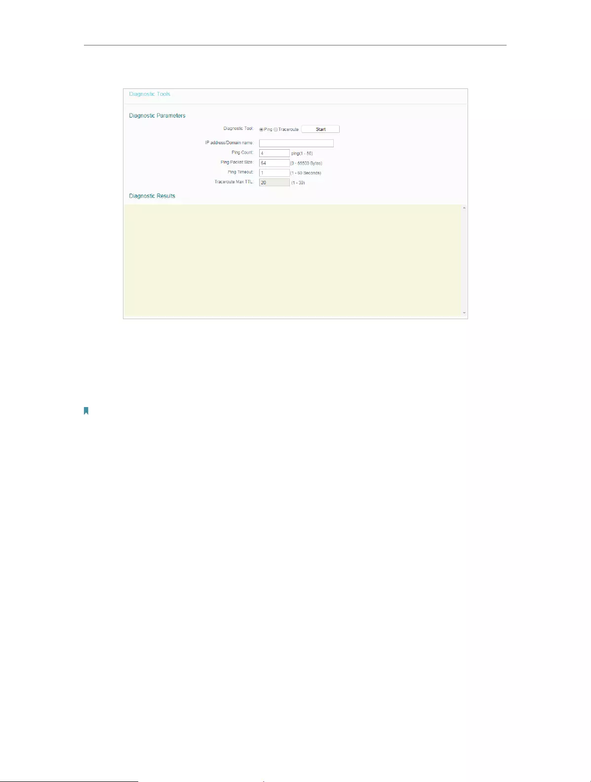
60
Chapter 4 Congure the Router
• Diagnostic Tool — Select one diagnostic tool.
• Ping — This diagnostic tool troubleshoots connectivity, reachability, and name
resolution to a given host or gateway.
• Tracerouter — This diagnostic tool tests the performance of a connection.
Note:
You can use ping/traceroute to test both numeric IP address or domain name. If pinging/tracerouting the IP address is
successful, but pinging/tracerouting the domain name is not, you might have a name resolution problem. In this case,
ensure that the domain name you are specifying can be resolved by using Domain Name System (DNS) queries.
• IP Address/Domain Name — Enter the destination IP address (such as 192.168.0.1) or
Domain name (such as www.tp-link.com).
• Pings Count — The number of Ping packets for a Ping connection.
• Ping Packet Size — The size of Ping packet.
• Ping Timeout — Set the waiting time for the reply of each Ping packet. If there is no
reply in the specified time, the connection is overtime.
• Traceroute Max TTL — The max number of hops for a Traceroute connection.
3. Click Start to check the connectivity of the internet.
4. The Diagnostic Results page displays the diagnosis result. If the result is similar to
the following figure, the connectivity of the internet is fine.
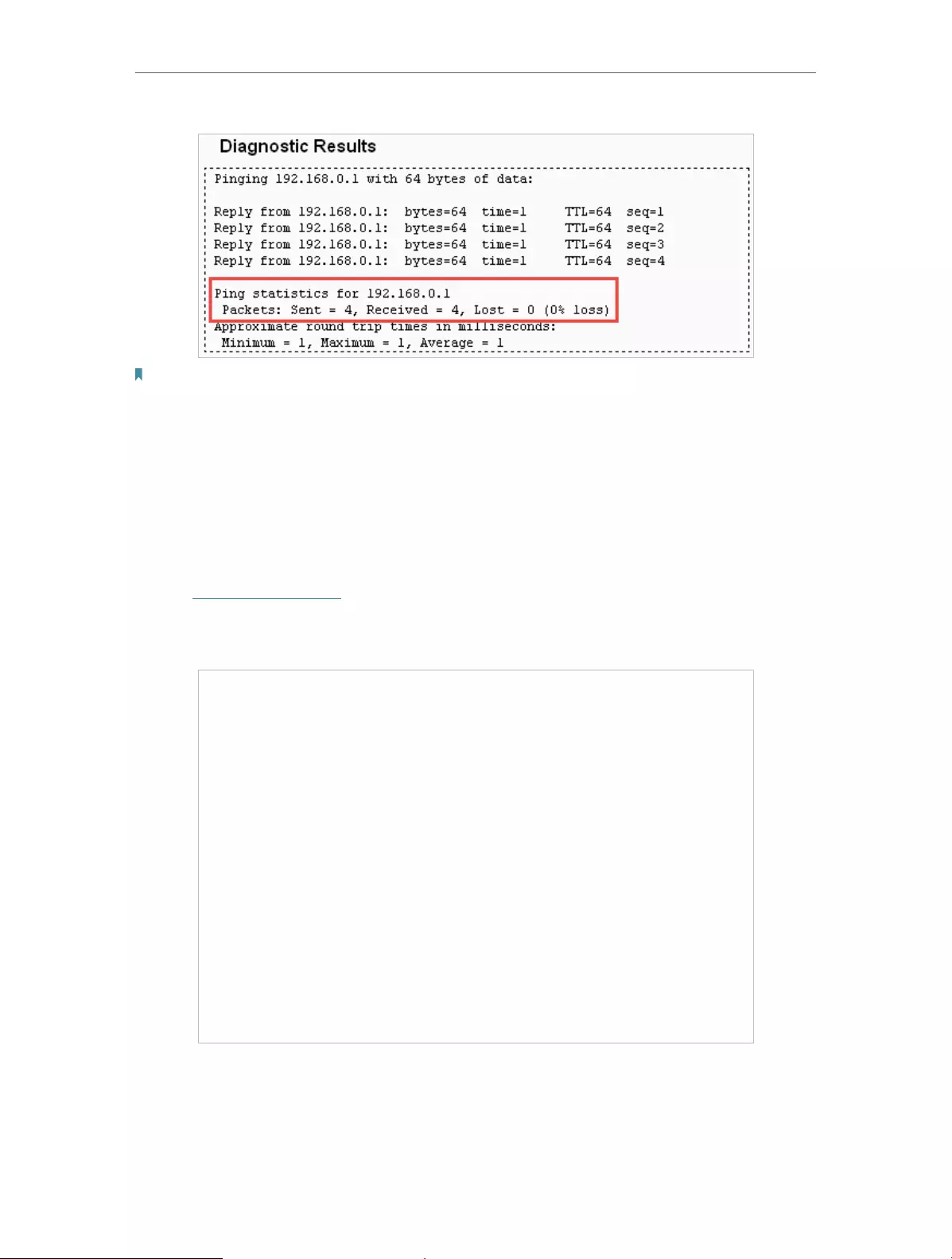
61
Chapter 4 Congure the Router
Note:
Only one user can use this tool at one time. Options “Ping Count”, “Ping Packet Size” and “Ping Timeout” are used for the
Ping function. Option “Traceroute Max TTL” is used for the Tracert function.
4. 15. 3. CWMP Settings
The router offers CWMP feature. The function supports TR-069 protocol which collects
information, diagnoses the devices and configures the devices automatically via ACS
(Auto-Configuration Server).
1. Visit http://tplinkwifi.net, and log in with the username and password you set for the
router.
2. Go to System Tools > CWMP Settings.
• CWMP:Enable the CWMP (CPE WAN Management Protocol) feature.
• Inform: Enable this feature to send an Inform message to the ACS (Auto Configuration
Server) periodically.
•

62
Chapter 4 Congure the Router
• Inform Interval: Enter the time interval in seconds when the Inform message will be
sent to the ACS.
• ACS URL: Enter the web address of the ACS which is provided by your ISP.
• ACS Username/Password: Enter the username/password to log in to the ACS server.
• Interface used by TR-069 client: Select which interface to be used by the TR-069
client.
• Display SOAP messages on serial console: Toggle to enable or disable this feature.
• Connection Request Authentication: Select this checkbox to enable authentication
for the connection request.
• Connection Request Username/Password: Enter the username/password for the ACS
server to log in to the router.
• Connection Request Path: Connection request path, for an ACS to make a connection
request notification to your router(CPE).
• Connection Request Port: Connection request server port, for an ACS to make a
connection request notification to your router(CPE).
• Connection Request URL: Connection request url, for an ACS to make a connection
request notification to your router(CPE).
• Get RPC methods: Click to get the methods to support CWMP.
3. Click Save.
4. 15. 4. Firmware Upgrade
TP-Link is dedicated to improving and richening the product features, giving users
a better network experience. We will release the latest firmware at TP-Link official
website. You can download the latest firmware file from the Support page of our website
www.tp-link.com and upgrade the firmware to the latest version.
1. Download the latest firmware file for the router from our website www.tp-link.com.
2. Visit http://tplinkwifi.net, and log in with the username and password you set for the
router.
3. Go to System Tools > Firmware Upgrade.
4. Click Choose File to locate the downloaded firmware file, and click Upgrade.

63
Chapter 4 Congure the Router
4. 15. 5. Factory Defaults
1. Visit http://tplinkwifi.net, and log in with the username and password you set for the
router.
2. Go to System Tools > Factory Defaults. Click Restore to reset all settings to the
default values.
• The default Username: admin
• The default Password: admin
• The default IP Address: 192.168.0.1
• The default Subnet Mask: 255.255.255.0
4. 15. 6. Backup & Restore
The configuration settings are stored as a configuration file in the router. You can
backup the configuration file in your computer for future use and restore the router to
the previous settings from the backup file when needed.
1. Visit http://tplinkwifi.net, and log in with the username and password you set for the
router.
2. Go to System Tools > Backup & Restore.
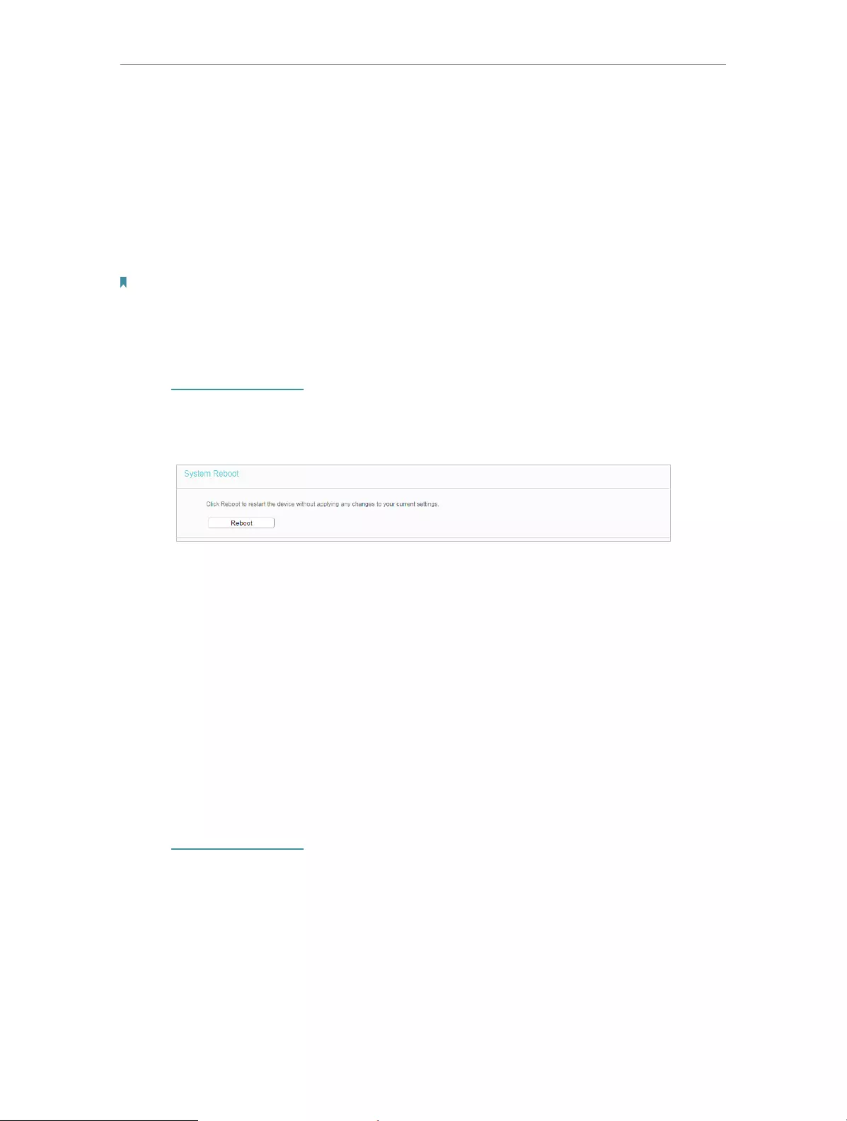
64
Chapter 4 Congure the Router
¾To backup configuration settings:
Click Backup to save a copy of the current settings in your local computer. A “.bin“ file
of the current settings will be stored in your computer.
¾To restore configuration settings:
1. Click Choose File to locate the backup configuration file stored in your computer, and
click Restore.
2. Wait a few minutes for the restoring and rebooting.
Note:
During the restoring process, do not power off or reset the router.
4. 15. 7. Reboot
1. Visit http://tplinkwifi.net, and log in with the username and password you set for the
router.
2. Go to System Tools > Reboot, and you can restart your router.
Some settings of the router will take effect only after rebooting, including:
• Change the LAN IP Address (system will reboot automatically).
• Change the DHCP Settings.
• Change the Working Modes.
• Change the Web Management Port.
• Upgrade the firmware of the router (system will reboot automatically).
• Restore the router to its factory defaults (system will reboot automatically).
• Update the configuration with the file (system will reboot automatically).
4. 15. 8. Password
1. Visit http://tplinkwifi.net, and log in with the username and password you set for the
router.
2. Go to System Tools > Password, and you can change the factory default username
and password of the router.
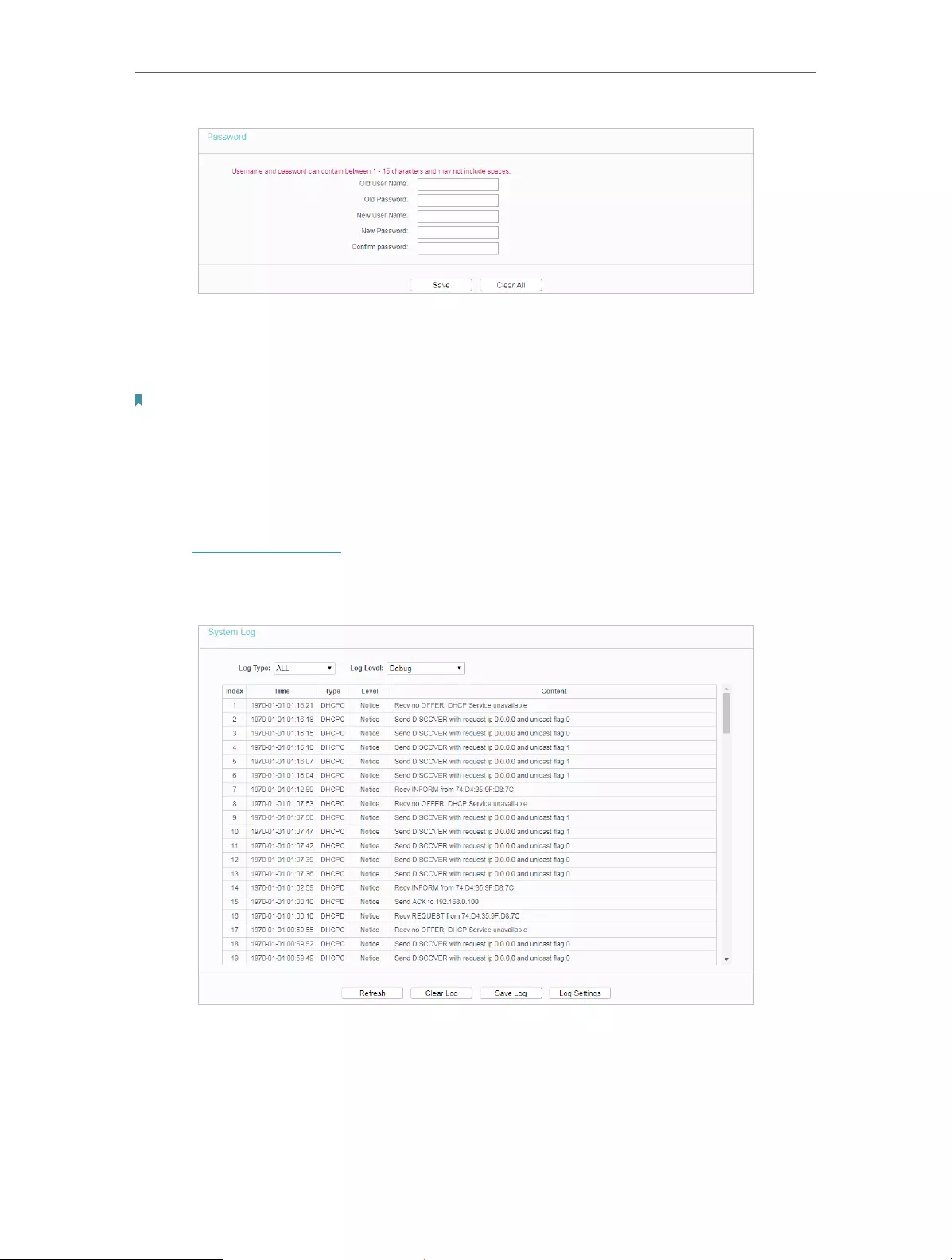
65
Chapter 4 Congure the Router
It is strongly recommended that you change the default username and password of the
router, for all users that try to access the router’s web-based utility or Quick Setup will
be prompted for the router’s username and password.
Note:
The new username and password must not exceed 15 characters and not include any spacing.
3. Click Save.
4. 15. 9. System Log
1. Visit http://tplinkwifi.net, and log in with the username and password you set for the
router.
2. Go to System Tools > System Log, and you can view the logs of the router.
• Log Type — By selecting the log type, only logs of this type will be shown.
• Log Level — By selecting the log level, only logs of this level will be shown.
• Refresh — Refresh the page to show the latest log list.
• Clear Log — All the logs will be deleted from the router permanently, not just from the
page.
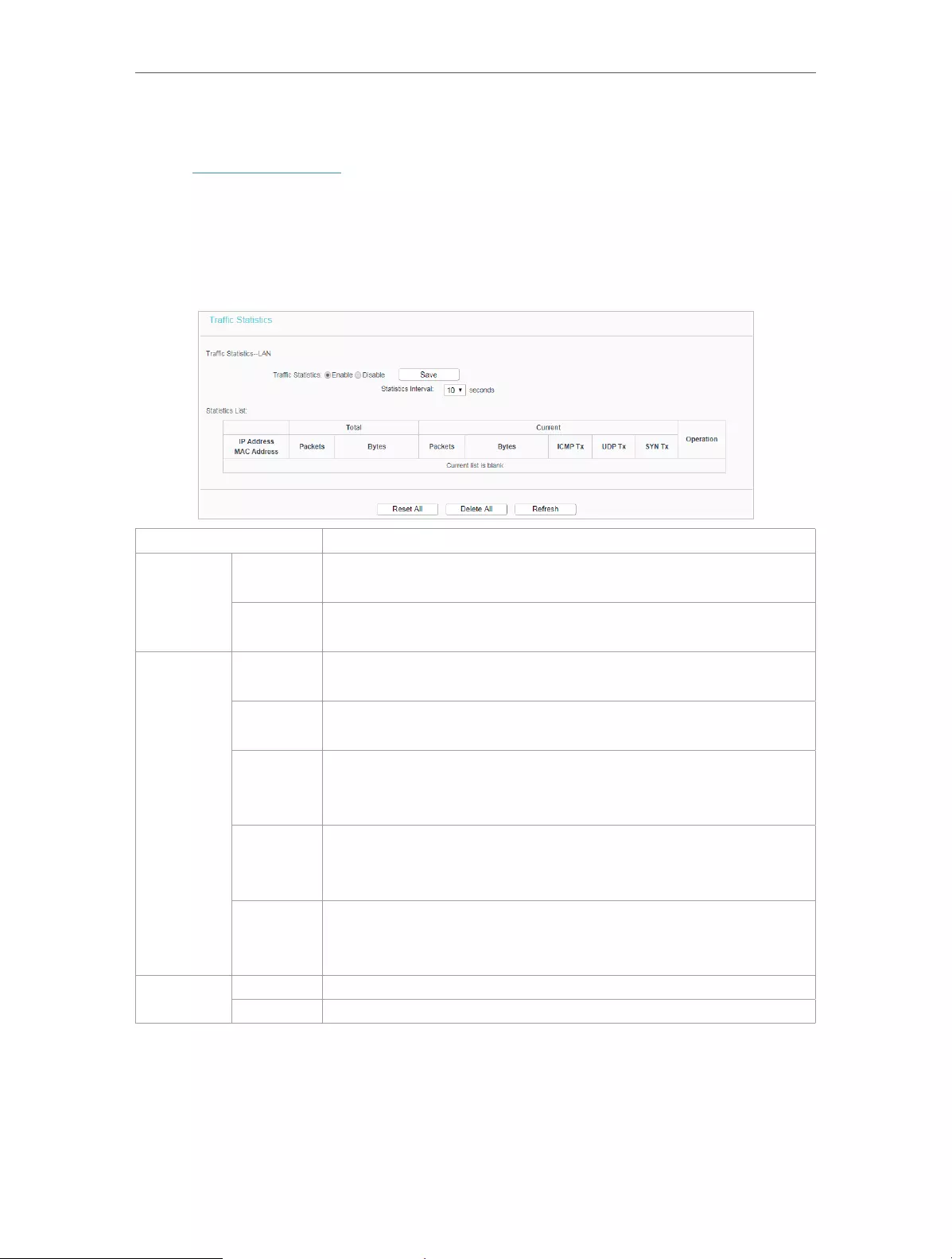
66
Chapter 4 Congure the Router
4. 15. 10. Statistics
1. Visit http://tplinkwifi.net, and log in with the username and password you set for the
router.
2. Go to System Tools > Statistics.
3. Enable Traffic Statistics and click Save to get the network traffic of each PC on the
LAN.
IP/MAC Address The IP and MAC address are displayed with related statistics.
Total
Packets The total number of packets received and transmitted by the
router.
Bytes The total number of bytes received and transmitted by the
router.
Current
Packets The total number of packets received and transmitted in the
last Packets Statistic interval seconds.
Bytes The total number of bytes received and transmitted in the last
Packets Statistic interval seconds.
ICMP Tx
The number of the ICMP packets transmitted to WAN per
second at the specified Packets Statistics interval. It is shown
like “current transmitting rate / Max transmitting rate”.
UDP Tx
The number of UDP packets transmitted to the WAN per
second at the specified Packets Statistics interval. It is shown
like “current transmitting rate / Max transmitting rate”.
TCP SYN
Tx
The number of TCP SYN packets transmitted to the WAN per
second at the specified Packets Statistics interval. It is shown
like “current transmitting rate / Max transmitting rate”.
Operation Reset Reset the value of he entry to zero.
Delete Delete the existing entry in the table.
4. 16. Log Out
Click Logout at the bottom of the main menu, and you will log out of the web page and
be directed to the login window.

67
FAQ
Q1. What should I do if I forget my wireless password?
The default wireless password is printed on the label of the router. If the password has
been altered, please connect your computer to the router using an Ethernet cable and
follow the steps below:
1. Visit http://tplinkwifi.net, and log in with the username and password you set for the
router.
2. Go to Wireless > Wireless Security to retrieve or reset your wireless password.
Q2. What should I do if I forget my login password of the web management
page?
The default username and password of the web management page are admin (in
lowercase).
If you have altered the username and password but Password Recovery is disabled:
1. Reset the router to factory default settings.
2. Visit http://tplinkwifi.net, and enter admin (in lowercase) as both username and
password to log in.
Note: You’ll need to reconfigure the router to surf the internet once the router is reset, and please mark down your new
password for future use.
Q3. What should I do if I cannot access the router’s web management
page?
1. Please try the methods below to log in again.
• Make sure your computer the has connected to the router correctly and the corresponding
LED light up.
• Make sure the IP address of your computer is configured as Obtain an IP address automatically
and Obtain DNS server address automatically.
2. Make sure you enter the correct IP address to log in: http://tplinkwifi.net.
• Check your computer’s settings:
3. Go to Start > Control Panel > Network and Internet, and click View network status
and tasks.
1 ) Click Internet Options on the bottom left.
2 ) Click Connections and select Never dial a connection.

68
3 ) Click LAN settings and deselect the following three options, and click OK.

69
4 ) Go to Advanced > Restore advanced settings, and click OK to save the settings.
• Use another web browser or computer to log in again.
• Reset the router to factory default settings and try again. If the login still fails, please contact
the technical support.
Note: You’ll need to reconfigure the router to surf the internet once the router is reset.
Q4. How do I use the WDS Bridging function to extend my wireless
network?
For example, my house covers a large area. The wireless coverage of the router I’m
using (the root router) is limited. I want to use an extended router to extend the wireless
network of the root router.
Note:
• WDS bridging only requires configuration on the extended router.
1. Visit http://tplinkwifi.net, and log in with the username and password you set for the
router.
2. Configure the IP address of the router:
1 ) Go to Network > LAN, configure the IP address of the extended router to be in the
same subnet with the root router; (For example, the IP address of the root router is
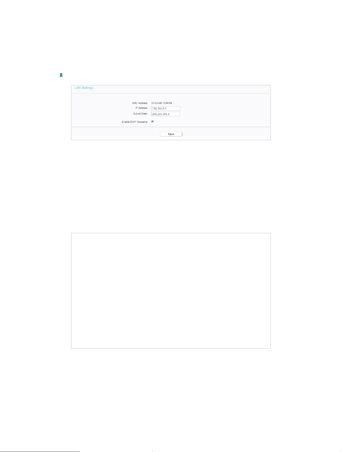
70
192.168.0.1, the IP address of the extended router can be 192.168.0.2~192.168.0.254.
We take 192.168.0.2 as example.)
2 ) Click Save.
Note: Log in to the web management page again if the IP address of the router is altered.
3. Survey the SSID to be bridged:
1 ) Go to Wireless > Basic Settings and click Enable WDS .
2 ) Click Scan, locate the root router’s SSID and click Choose (Here we take
TP-Link_2512 as example).
3 ) If the root router is set with a wireless password, you should enter the wireless password
of the root router.
4 ) Click Save.
4. Disable DHCP:
1 ) Go to DHCP, select Disable, and click Save.
Now you can go to Status to check the WDS status. When the WDS status is Run, it
means WDS bridging is successfully built.

71
Q5. What should I do if I cannot access the internet even though the
configuration is finished?
1. Visit http://tplinkwifi.net, and log in with the username and password you set for the
router.
2. Go to Status to check WAN status:
If IP Address is a valid one, please try the methods below and try again:
• Your computer might not recognize any DNS server addresses, please manually configure
DNS server.
1 ) Go to DHCP.
2 ) Enter 8.8.8.8 as Primary DNS, and click Save.
Tips: 8.8.8.8 is a safe and public DNS server operated by Google.
• Restart the modem and the router.
1 ) Power off your modem and the router, and leave them off for 1 minute.
2 ) Power on your modem first, and wait about 2 minutes.
3 ) Power on the router, and wait another 1 or 2 minutes and check the internet access.
• Reset the router to factory default settings and reconfigure the router.
• Upgrade the firmware of the router.
• Check the TCP/IP settings on the particular device if all other devices can get internet from
the router.
If the IP Address is 0.0.0.0, please try the methods below and try again:
• Make sure the physical connection between the router and the modem is proper.
• Clone the MAC address of your computer.
1 ) Visit http://tplinkwifi.net, and log in with the username and password you set for the
router.
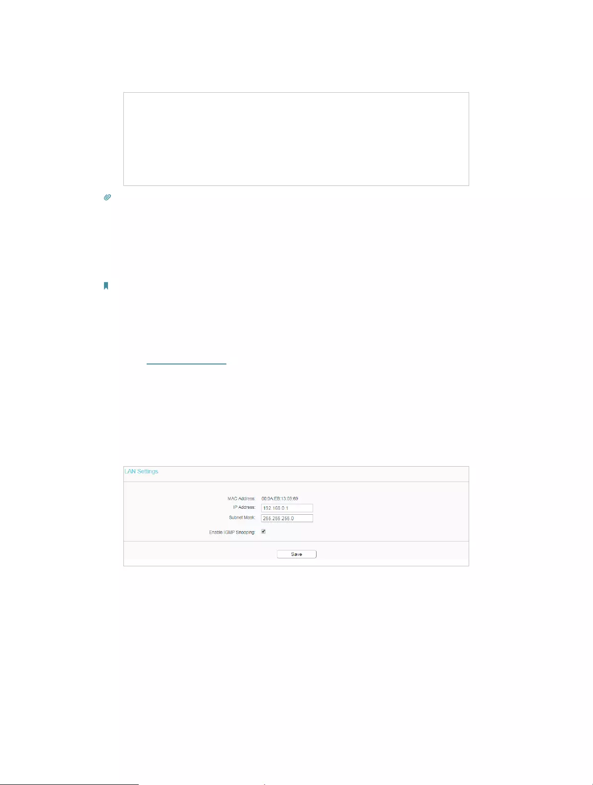
72
2 ) Go to Network > MAC Clone, select Clone MAC Address and click Save.
Tips:
• Some ISPs will register the MAC address of your computer when you access the internet for the first time
through their Cable modem, if you add a router into your network to share your internet connection, the ISP will
not accept it as the MAC address is changed, so we need to clone your computer’s MAC address to the router.
• The MAC addresses of a computer in wired connection and wireless connection are different.
• Modify the LAN IP address of the router.
Note:
Most TP-Link routers use 192.168.0.1/192.168.1.1 as their default LAN IP address, it may conflict with the IP range
of your existent ADSL modem/router. If so, the router is not able to communicate with your modem and cause you
can’t access the internet. To resolve this problem, we need to change the LAN IP address of the router to avoid
such conflict, for example, 192.168.2.1.
1 ) Visit http://tplinkwifi.net, and log in with the username and password you set for the
router.
2 ) Go to Network > LAN.
3 ) Modify the LAN IP address as the follow picture shows. Here we take 192.168.2.1 as an
example.
4 ) Click Save.
• Restart the modem and the router.
1 ) Power off your modem and the router, and leave them off for 1 minute.
2 ) Power on your modem first, and wait about 2 minutes.
3 ) Power on the router, and wait another 1 or 2 minutes and check the internet access.
• Double check the internet Connection Type.
1 ) Confirm your internet Connection Type, which can be learned from the ISP.

73
2 ) Visit http://tplinkwifi.net, and log in with the username and password you set for the
router.
3 ) Go to Network > WAN.
4 ) Select your WAN Connection Type and fill in other parameters.
5 ) Click Save.
6 ) Restart the modem and the router.
• Please upgrade the firmware of the router.
If you’ve tried every method above but cannot access the internet, please contact the
technical support.
Q6. What should I do if I cannot find my wireless network or I cannot
connect the wireless network?
If you fail to find any wireless network, please follow the steps below:
• Make sure the wireless function of your device is enabled if you’re using a laptop with a built-in
wireless adapter. You can refer to the relevant document or contact the laptop manufacturer.
• Make sure the wireless adapter driver is installed successfully and the wireless adapter is
enabled.
• On Windows 7
1 ) If you see the message No connections are available, it is usually because the wireless
function is disabled or blocked somehow.
2 ) Clicking Troubleshoot and windows might be able to fix the problem by itself.
• On Windows XP

74
1 ) If you see the message Windows cannot configure this wireless connection, this is
usually because windows configuration utility is disabled or you are running another
wireless configuration tool to connect the wireless.
2 ) Exit the wireless configuration tool (the TP-Link Utility, for example).
3 ) Select and right click My Computer on Desktop, and select Manage to open Computer
Management window.
4 ) Expand Services and Applications > Services, and find and locate Wireless Zero
Configuration in the Services list on the right side.
5 ) Right click Wireless Zero Configuration, and then select Properties.
6 ) Change Startup type to Automatic, click Start and make sure the Service status is
Started. And then click OK.
If you can find other wireless network except your own, please follow the steps below:
• Check the WLAN LED indicator on your wireless router/modem.
• Make sure your computer/device is still in the range of your router/modem. Move closer if it is
currently too far away.
If you can find your wireless network but fail to connect, please follow the steps below:
• Authenticating problem/password mismatch:
1 ) Sometimes you will be asked to type in a PIN number when you connect to the wireless
network for the first time. This PIN number is different from the Wireless Password/
Network Security Key. Usually you can only find it on the label of your router.
2 ) If you cannot find the PIN or PIN failed, you may choose Connecting using a security
key instead, and then type in the Wireless Password/Network Security Key.
3 ) If it continues to show note of Network Security Key Mismatch, it is suggested to
confirm the wireless password of your wireless router.
Note: Wireless Password/Network Security Key is case sensitive.
• Windows unable to connect to XXXX / Can not join this network / Taking longer than usual
to connect to this network:

75
• Check the wireless signal strength of your network, if it is weak (1~3 bars), please move
the router closer and try again.
• Change the wireless Channel of the router to 1, 6, or 11 to reduce interference from
other networks.
• Re-install or update the driver for your wireless adapter of the computer.

76
COPYRIGHT & TRADEMARKS
Specifications are subject to change without notice. is a registered trademark
of TP-Link Technologies Co., Ltd. Other brands and product names are trademarks or
registered trademarks of their respective holders.
No part of the specifications may be reproduced in any form or by any means or used
to make any derivative such as translation, transformation, or adaptation without
permission from TP-Link Technologies Co., Ltd. Copyright © 2018 TP-Link Technologies
Co., Ltd. All rights reserved.

77
FCC STATEMENT
This equipment has been tested and found to comply with the limits for a Class B digital
device, pursuant to part 15 of the FCC Rules. These limits are designed to provide
reasonable protection against harmful interference in a residential installation. This
equipment generates, uses and can radiate radio frequency energy and, if not installed
and used in accordance with the instructions, may cause harmful interference to radio
communications. However, there is no guarantee that interference will not occur in a
particular installation. If this equipment does cause harmful interference to radio or
television reception, which can be determined by turning the equipment off and on, the
user is encouraged to try to correct the interference by one or more of the following
measures:
• Reorient or relocate the receiving antenna.
• Increase the separation between the equipment and receiver.
• Connect the equipment into an outlet on a circuit different from that to which the
receiver is connected.
• Consult the dealer or an experienced radio/ TV technician for help.
This device complies with part 15 of the FCC Rules. Operation is subject to the following
two conditions:
1. This device may not cause harmful interference.
2. This device must accept any interference received, including interference that may cause
undesired operation.
Any changes or modifications not expressly approved by the party responsible for
compliance could void the user’s authority to operate the equipment.
Note: The manufacturer is not responsible for any radio or TV interference caused by
unauthorized modifications to this equipment. Such modifications could void the user’s
authority to operate the equipment.
FCC RF Radiation Exposure Statement
This equipment complies with FCC RF radiation exposure limits set forth for an
uncontrolled environment. This device and its antenna must not be co-located or
operating in conjunction with any other antenna or transmitter.
“To comply with FCC RF exposure compliance requirements, this grant is applicable to
only Mobile Configurations. The antennas used for this transmitter must be installed to
provide a separation distance of at least 20 cm from all persons and must not be co-
located or operating in conjunction with any other antenna or transmitter.”

78
CE Mark Warning
This is a class B product. In a domestic environment, this product may cause radio
interference, in which case the user may be required to take adequate measures.
OPERATING FREQUENCY(the maximum transmitted power)
2412MHz—2472MHz(20dBm)
5180MHz—5240MHz(23dBm)
EU declaration of conformity
TP-Link hereby declares that the device is in compliance with the essential requirements
and other relevant provisions of directives 2014/53/EU, 2009/125/EC and 2011/65/EU.
The original EU declaration of conformity may be found at http://www.tp-link.com/en/ce
RF Exposure Information
This device meets the EU requirements (2014/53/EU Article 3.1a) on the limitation of
exposure of the general public to electromagnetic fields by way of health protection.
The device complies with RF specifications when the device used at 20 cm from your
body.
Restricted to indoor use.
Продукт сертифіковано згідно с правилами системи УкрСЕПРО на відповідність
вимогам нормативних документів та вимогам, що передбачені чинними
законодавчими актами України.
Safety Information
• Keep the device away from water, fire, humidity or hot environments.
• Do not attempt to disassemble, repair, or modify the device.
• Do not use damaged charger or USB cable to charge the device.
• Do not use any other chargers than those recommended
• Do not use the device where wireless devices are not allowed.
• Adapter shall be installed near the equipment and shall be easily accessible.
• Use only power supplies which are provided by manufacturer and in the original
packing of this product. If you have any questions, please don’t hesitate to contact us.

79
Please read and follow the above safety information when operating the device. We
cannot guarantee that no accidents or damage will occur due to improper use of the
device. Please use this product with care and operate at your own risk.
For EU/EFTA, this product can be used in the following countries:
AT BE BG CH CY CZ DE DK
EE EL ES FI FR HR HU IE
IS IT LI LT LU LV MT NL
NO PL PT RO SE SI SK UK
Explanations of the symbols on the product label
Symbol Explanation
DC voltage
Indoor use only
RECYCLING
This product bears the selective sorting symbol for Waste electrical and electronic equipment
(WEEE). This means that this product must be handled pursuant to European directive 2012/19/
EU in order to be recycled or dismantled to minimize its impact on the environment.
User has the choice to give his product to a competent recycling organization or to the retailer
when he buys a new electrical or electronic equipment.
-
Page 1
User Guide 300Mbps Wireless N Router TL-WR850N 1910020832 REV2.0.0… -
Page 2: Table Of Contents
Contents About This Guide ………………….1 Chapter 1. Get to Know Your Router ……..2 1.
-
Page 3
8. 2. Share Local Resources over the Internet by Virtual Server ….37 8. 3. Open Ports Dynamically by Port Triggering ……..38 8. -
Page 4
11. 6. 3. Remote Management ……….76 11. -
Page 5: About This Guide
The Quick Installation Guide can be found where you find this guide or inside the package of the router. Specifications can be found on the product page at http://www.tp-link.com. A Technical Support Forum is provided for you to discuss our products at http://forum.tp-link.com.
-
Page 6: Chapter 1. Get To Know Your Router
Chapter Get to Know Your Router This chapter introduces what the router can do and shows its appearance. This chapter contains the following sections: • Product Overview • Appearance…
-
Page 7: Product Overview
Wi-Fi signal to all your devices while boosting widespread coverage throughout your home, and the built-in Ethernet ports supply high-speed connection to your wired devices. Moreover, it is simple and convenient to set up and use the TP-Link router due to its intuitive web interface. 1. 2.
-
Page 8: Back Panel
Chapter 1 Get to Know Your Router LED Explanation Name Status Indication The system has started up successfully. The system is starting up or the router is updating the firmware. Flashing (Power) Do not disconnect or power off the router. Power is off.
-
Page 9
Chapter 1 Get to Know Your Router The router’s back panel contains the connection ports, buttons and antennas. Refer to the following for detailed instructions. Item Description Power Port For connecting the router to a power socket via the provided power adapter. WAN Port For connecting the router to a DSL/Cable modem, or an Ethernet port. -
Page 10: Chapter 2. Connect The Hardware
Chapter Connect the Hardware This chapter contains the following sections: • Position Your Router • Connect Your Router…
-
Page 11: Position Your Router
Chapter 2 Connect the Hardware 2. 1. Position Your Router • The product should not be located in a place where it will be exposed to moisture or excessive heat. • Place the router in a location where it can be connected to multiple devices as well as to a power source.
-
Page 12
Chapter 2 Connect the Hardware Power Wi-Fi Internet 6. Connect your computer to the router. • Method 1: Wired Turn off the Wi-Fi on your computer and connect the devices as shown below. Ethernet cable WPS/ POWER RESET • Method 2: Wireless 1 ) Find the SSID (Network Name) and Wireless Password printed on the label at the bottom of the router. -
Page 13
Chapter 2 Connect the Hardware 2 ) Immediately press the WPS/RESET button on your router. WLAN TP-Link Home Office TP-Link_123 TP-Link_abc MyHome Test Close to TP-Link_5G WPS/ POWER RESET… -
Page 14: Chapter 3. Log In To Your Router
Chapter Log In to Your Router…
-
Page 15
Chapter 3 Log In to Your Router With a web-based utility, it is easy to configure and manage the router. The web-based utility can be used on any Windows, Macintosh or UNIX OS with a Web browser, such as Microsoft the Internet Explorer, Mozilla Firefox or Apple Safari. Follow the steps below to log in to your router. -
Page 16: Chapter 4. Set Up Internet Connection
Chapter Set Up Internet Connection This chapter introduces how to connect your router to the internet. The router is equipped with a web-based Quick Setup wizard. It has necessary ISP information built in, automates many of the steps and verifies that those steps have been successfully completed.
-
Page 17: Use Quick Setup Wizard
Chapter 4 Set Up Internet Connection 4. 1. Use Quick Setup Wizard The Quick Setup Wizard will guide you through the process to set up your router. Tips: If you need the IPv6 internet connection, please refer to the section of Set Up an IPv6 Internet Connection.
-
Page 18
Chapter 4 Set Up Internet Connection 2 ) If you choose Static IP, enter the information provided by your ISP in the corresponding fields. 3 ) If you choose PPPoE, enter the Username Password and choose Secondary Connection provided by your ISP. Different parameters are needed according to the Secondary Connection type you have chosen. -
Page 19: Set Up An Ipv6 Internet Connection
Chapter 4 Set Up Internet Connection 5 ) If you choose PPTP, enter the Username and Password, and select the Address Type provided by your ISP. Different parameters are needed according to the IP address type you selected. 5. Click Save to make the settings effective, and you can refer to Test Internet…
-
Page 20: More Operation Modes
Chapter 4 Set Up Internet Connection 1. Visit http://tplinkwifi.net, and log in with the password you set for the router. 2. Go to Advanced > Network > Internet. 3. Select your WAN Interface Name (Status should be Connected) and click the (edit) icon.
-
Page 21: Configure The Router In Range Extender Mode
Chapter 4 Set Up Internet Connection Internet Ethernet1Ethernet2 Ethernet3 Ethernet4 Ethernet Wired Router Router Devices 1. Connect the router’s WAN port to your wired router’s Ethernet port via an Ethernet cable as shown above. And power on the router. 2. Connect a computer to the router via an Ethernet cable or wirelessly by using the SSID (network name) and Wireless Password printed on the label at the bottom of the router.
-
Page 22
Chapter 4 Set Up Internet Connection 4. Go to Settings Advanced > Operation Mode, select Range Extender and click Save. Log in to the router via http://tplinkwifi.net after the router reboots. 5. Configure the basic settings of the wireless network. •… -
Page 23
Chapter 4 Set Up Internet Connection 3 ) Enter the Password of the host network you selected, and click Save to make the settings effective. ¾ To specify the extended network: 1 ) Go to Settings > Wireless > Extended Network, and configure the basic settings of the extended network. -
Page 24
Chapter 4 Set Up Internet Connection • Network Name (SSID): Enter a new SSID (up to 32 characters long) or just use the SSID of the default name copied from the host network. This field is case-sensitive. Do not select Hide SSID unless you want the client devices to join the network manually. -
Page 25: Chapter 5. Parental Controls
Chapter Parental Controls This function allows you to block inappropriate, explicit and malicious websites, and control access to specified websites at specified time.
-
Page 26
For example, I want to allow my children’s devices (e.g. a computer or a tablet) to access only www.tp-link.com and Wikipedia.org from 18:00 (6 PM) to 22:00 (10 PM) on the weekdays and not other time. How can I 1. -
Page 27
Effective Time period. • With Whitelist selected, the controlled devices can only access websites containing the specified keywords during the Effective Time period. 7. Click Add a New Keyword and enter “www.tp-link.com” and “Wikipedia.org” as the keywords and click Save. -
Page 28
Chapter 5 Parental Controls 8. You can add up to 32 keywords for either Blacklist or Whitelist. Below are some sample entries for your reference. • Whitelist: Enter a web address (e.g. wikipedia.org) to allow access only to its related websites. If you wish to block all Internet browsing access, do not add any keyword to the Whitelist. -
Page 29: Chapter 6. Bandwidth Control
Chapter Bandwidth Control This chapter describes how to use the Bandwidth Control function to control the bandwidth by configuring rules for limiting various data flows. In this way, the network bandwidth can be reasonably distributed and utilized. It contains the following sections: •…
-
Page 30: Configure The Bandwidth Control
Chapter 6 Bandwidth Control 6. 1. Configure the Bandwidth Control Bandwidth Control allows you to configure the Upstream Bandwidth and Downstream Bandwidth of the network, follow the steps below to configure the bandwidth. 1. Visit http://tplinkwifi.net, and log in with the password you set for the router. 2.
-
Page 31
Chapter 6 Bandwidth Control 2. Enter a range of IP addresses and port numbers to be controlled. IP Range: The field can be a single IP address or IP address range according to your needs. If you set the IP Range to a single IP address, the computer with this IP address will get independent given bandwidth. -
Page 32: Chapter 7. Network Security
Chapter Network Security This chapter guides you on how to protect your home network from unauthorized users by implementing network security functions. You can block or allow specific client devices to access your wireless network using MAC Filtering, or using Access Control for wired and wireless networks, or you can prevent ARP spoofing and ARP attacks by using IP &…
-
Page 33: Firewall & Dos Protection
Network Security Chapter 7 7. 1. Firewall & DoS Protection The SPI (Stateful Packet Inspection) Firewall and DoS (Denial of Service) Protection protect the router from cyber attacks. The SPI Firewall can prevent cyber attacks and validate the traffic that is passing through the router based on the protocol.
-
Page 34: Service Filtering
Network Security Chapter 7 2. The protection will be triggered immediately when the number of packets exceeds the preset threshold value, and the vicious host will be displayed in the Blocked DoS Host List. 7. 2. Service Filtering With Service Filtering, you can prevent certain users from accessing the specified service, and even block internet access completely.
-
Page 35: Access Control
Network Security Chapter 7 4. Select a Service Type from the drop-down list and the following four fields will be automatically filled in. Select Custom when your desired service type is not listed, and enter the information manually. 5. Specify the IP address(es) that this filtering rule will apply to. 6.
-
Page 36
Network Security Chapter 7 3. Select the access mode to either block (recommended) or allow the device(s) to access your network. To block specific device(s): 1 ) Select Blacklist and click Save. 2 ) Select the device(s) to be blocked in the Online Devices table (or click the under the… -
Page 37: Ip & Mac Binding
Network Security Chapter 7 3 ) Enter the Device Name Address. (You can copy and paste the information from Online Devices table if the device is connected to your network.) 4 ) Click Save. Done! Now you can block or allow specific client devices to access your network (via wired or wireless) by Blacklist or Whitelist.
-
Page 38
Network Security Chapter 7 3. Bind your device(s) according to your needs. To bind the connected device(s): 1 ) Select the device(s) to be bound in the List. 2 ) Click Bind to add to the Binding List. To bind the unconnected device: 1 ) Click in the Binding List… -
Page 39: Chapter 8. Nat Forwarding
TP-Link router includes four forwarding rules. If two or more rules are set, the priority of implementation from high to low is Virtual Servers, Port Triggering, UPnP and DMZ.
-
Page 40: Translate Address And Port By Alg
Chapter 8 NAT Forwarding 8. 1. Translate Address and Port by ALG ALG (Application Layer Gateway) allows customized NAT (Network Address Translation) traversal filters to be plugged into the gateway to support address and port translation for certain application layer “control/data” protocols: FTP, TFTP etc. Enabling ALG is recommended.
-
Page 41: Share Local Resources Over The Internet By Virtual Server
Chapter 8 NAT Forwarding 8. 2. Share Local Resources over the Internet by Virtual Server When you build up a server in the local network and want to share it on the internet, Virtual Server can realize the service and provide it to the internet users. At the same time virtual server can keep the local network safe as other services are still invisible from the internet.
-
Page 42: Open Ports Dynamically By Port Triggering
Chapter 8 NAT Forwarding 4. Click Scan, and select HTTP. The external port, internal port and protocol will be automatically filled in. Enter the PC’s IP address 192.168.0.100 in the Internal IP field. 5. Click Save to save the settings. Tips: 1.
-
Page 43: Make Applications Free From Port Restriction By Dmz
Chapter 8 NAT Forwarding address of the host. When the data from the internet returns to the external ports, the router can forward them to the corresponding host. Port triggering is mainly applied to online games, VoIPs and video players. Common applications include MSN Gaming Zone, Dialpad, Quick Time 4 players, and so on.
-
Page 44: Make Xbox Online Games Run Smoothly By Upnp
Chapter 8 NAT Forwarding applications, like IP camera and database software, you can set the PC to be a DMZ host. Note: DMZ is most applicable when you don’t know which ports to open. When it is enabled, the DMZ host is totally exposed to the internet, which may bring some potential safety hazards.
-
Page 45
Chapter 8 NAT Forwarding such as multiplayer gaming, peer-to-peer connections, real-time communication (for example, VoIP or telephone conference), or remote assistance. Tips: 1. Only the application supporting UPnP protocol can use this feature. 2. UPnP feature needs the support of operating system (e.g. Windows Vista/ Windows 7/ Windows 8, etc. Some operating systems need to install the UPnP components). -
Page 46: Chapter 9. Vpn Server
Chapter VPN Server The VPN (Virtual Private Networking) Server allows you to access your home network in a secured way through internet when you are out of home. The router offers two ways to setup VPN connection: OpenVPN and PPTP (Point to Point Tunneling Protocol) VPN. OpenVPN is somewhat complex but with greater security and more stable.
-
Page 47: Use Openvpn To Access Your Home Network
Chapter 9 VPN Server 9. 1. Use OpenVPN to Access Your Home Network In the OpenVPN connection, the home network can act as a server, and the remote device can access the server through the router which acts as an OpenVPN Server gateway.
-
Page 48: Use Pptp Vpn To Access Your Home Network
Chapter 9 VPN Server 7. Click Save. 8. Click Generate to get a new certificate. Note: If you have already generated one, please skip this step, or click Generate to update the certificate. 9. Click Export to save the OpenVPN configuration file which will be used by the remote device to access your router.
-
Page 49
Chapter 9 VPN Server Note: Before you enable Server, we recommend you configure Dynamic DNS Service (recommended) or assign a static IP address for router’s WAN port and synchronize your System Time with internet. 3. In the Client IP Address filed, enter the range of IP addresses (up to 10) that can be leased to the devices by the PPTP VPN server. -
Page 50
Chapter 9 VPN Server 4. Select Use my Internet connection (VPN). 5. Enter the internet IP address of the router (for example: 218.18.1.73) in the Internet address field. Click Next. -
Page 51
Chapter 9 VPN Server 6. Enter the User name Password you have set for the PPTP VPN server on your router, and click Connect. 7. The PPTP VPN connection is created and ready to use. -
Page 52
Chapter 9 VPN Server Tips: You can go to Advanced > > VPN Connections to view the clients that are currently connected to the PPTP VPN servers. -
Page 53: Chapter 10. Customize Your Network Settings
Chapter Customize Your Network Settings This chapter introduces how to change the default settings or adjust the basic configuration of the router using the web management page. It contains the following sections: • Configure LAN Settings • Configure IPv6 LAN Settings •…
-
Page 54: Configure Lan Settings
Chapter 10 Customize Your Network Settings 10. 1. Configure LAN Settings 10. 1. 1. Change the LAN IP Address The router is preset with a default LAN IP 192.168.0.1, which you can use to log in to its web management page. The LAN IP address together with the Subnet Mask also defines the subnet that the connected devices are on.
-
Page 55: Use The Router As A Dhcp Server
Chapter 10 Customize Your Network Settings 10. 1. 2. Use the Router as a DHCP Server You can configure the router to act as a DHCP server to assign IP addresses to its clients. To use the DHCP server function of the router, you must configure all computers on the LAN to obtain an IP Address automatically.
-
Page 56: Configure Ipv6 Lan Settings
Chapter 10 Customize Your Network Settings when it accesses the DHCP server. If there are some devices in the LAN that require permanent IP addresses, please configure Address Reservation on the router for the purpose. Follow the steps below to reserve an IP address for your devices. 1.
-
Page 57: Configure The Dhcpv6 Server Address Type
Chapter 10 Customize Your Network Settings 1 ) Select RADVD as the address type to make the router assign IPv6 address prefixes to hosts. Note: Do not select the Enable RDNSS Enable ULA Prefix check boxes unless required by your ISP. Otherwise you may not be able to access the IPv6 network.
-
Page 58: Set Up A Dynamic Dns Service Account
Chapter 10 Customize Your Network Settings 1 ) Select DHCPv6 Server as the address type to make the router assign IPv6 addresses to hosts. 2 ) Specify the Starting/Ending IPv6 Address for the IPv6 suffixes. The router will generate IPv6 addresses within the specified range. 3 ) Keep Address Lease Time as the default setting.
-
Page 59: Create Interface Groups
Chapter 10 Customize Your Network Settings 4. Log in with your DDNS account, select a service provider and click Go to register … Enter the username, password and domain name of the account (such as lisa.ddns. net). 5. Click Log in and Save.
-
Page 60: Create Static Routes
Chapter 10 Customize Your Network Settings 3. Click to create a new group. 4. Name the group. 5. Select LAN1 and LAN3 in Available LAN. Wireless network Wi-Fi 2.4G is viewed as a LAN interface. 6. Select the Enable Group Isolation check box to isolate working devices and disallow other devices from communicating with them.
-
Page 61
Chapter 10 Customize Your Network Settings Router A Router B Company’s Server WAN: 172.30.30.100 LAN: 192.168.0.1 LAN: 192.168.0.2 172.30.30.1 Switch My PC 192.168.0.100 How can I 1. Make sure the routers use different LAN IP addresses on the do that? same subnet. -
Page 62
Chapter 10 Customize Your Network Settings • Network Destination: The destination IP address that you want to assign to a static route. This IP address cannot be on the same subnet with the WAN IP or LAN IP of the Router A. In the example, the IP address of the company network is the destination IP address, so here we enter 172.30.30.1. -
Page 63: Set Up The Ipv6 Tunnel
Chapter 10 Customize Your Network Settings 10. 6. Set Up the IPv6 Tunnel The IPv6 Tunnel feature helps you obtain IPv6 resources based on an IPv4 WAN connection or vice versa. IPv6 Tunnel is a transition mechanism that enables IPv6-only hosts to reach IPv4 services or vice versa and allows isolated IPv6 hosts and networks to reach each other over IPv4-only infrastructure before IPv6 completely supplants IPv4.
-
Page 64: Specify The 6Rd Tunnel With Parameters Provided By Your Isp
Chapter 10 Customize Your Network Settings 10. 6. 2. Specify the 6rd Tunnel with Parameters Provided by Your ISP I want to: Specify the 6rd tunnel with the parameters provided by my 6rd tunnel service provider. How can I How can I 1.
-
Page 65: Specify Wireless Settings
Chapter 10 Customize Your Network Settings 10. 7. Specify Wireless Settings 10. 7. 1. Change Basic Wireless Settings The router’s wireless network name (SSID) and password, and security option are preset in the factory. The preset SSID and password can be found on the product label. You can customize the wireless settings according to your needs.
-
Page 66
Chapter 10 Customize Your Network Settings 2. Select the wireless network mode or channel and click Save to make the settings effective. Mode: Select the desired transmission mode. • 802.11n only: Select only if all of your wireless clients are 802.11n devices. •… -
Page 67: Advanced Wireless Settings
Chapter 10 Customize Your Network Settings 10. 7. 2. Advanced Wireless Settings Advanced wireless settings are for those who want more network controls. You can follow the instructions below to configure your router. 1. Visit http://tplinkwifi.net, and log in with the password you set for your router. 2.
-
Page 68
Chapter 10 Customize Your Network Settings Note: If you are not familiar with the settings on this page, it’s strongly recommended that you keep the provided default values; otherwise it may result in lower wireless network performance. ¾ To enable WDS bridging function: Locate the section and select the Enable WDS Bridging… -
Page 69: Schedule Your Wireless Function
Chapter 10 Customize Your Network Settings 3 ) Select the Security option for the guest-SSID network, WPA/WPA2 Personal recommended, and you can set a password for the network. If you want to allow the wireless devices on the guest-SSID network to communicate with each other via methods such as network neighbors, Samba, Ping, and FTP, select the Allow Guests to Access Each Other…
-
Page 70: View Wireless Information
Chapter 10 Customize Your Network Settings 2. The wireless LED will turn off if the corresponding wireless network is disabled. 3. The wireless network will be automatically turned on after the time period you set. 10. 7. 4. View Wireless Information ¾…
-
Page 71
Chapter 10 Customize Your Network Settings 4. When the WPS LED is on, the client device has successfully connected to the router. Method 2: Use the WPS button on the web management page Use this method if your client device has a WPS button. 1. -
Page 72
Chapter 10 Customize Your Network Settings 2. The WPS function cannot be configured if the wireless function of the router is disabled. Please make sure the wireless function is enabled before configuring WPS. Method 4: Enter the client device’s PIN on the router 1. -
Page 73: Chapter 11. Manage Your Router
Chapter Manage Your Router This chapter introduces how to change the system settings and administrate your router’s network. This chapter contains the following sections: • Set System Time • Test Internet Connectivity • Update the Firmware • Back Up and Restore Configuration Settings •…
-
Page 74: Set System Time
Chapter 11 Manage Your Router 11. 1. Set System Time System time is the time displayed while the router is running. The system time you configure here will be used for other time-based functions like Parental Controls and Wireless Schedule. You can manually set how to get the system time. Follow the steps below to set your system time.
-
Page 75: Test Internet Connectivity
Chapter 11 Manage Your Router 11. 2. Test Internet Connectivity Diagnostics function is used to test the connectivity between the router and the host or other network devices. 1. Visit http://tplinkwifi.net, and log in with the password you set for your router. 2.
-
Page 76: Update The Firmware
3. DO NOT turn off the router during the firmware upgrade. You can follow the steps below to manually update the firmware. 1. Download the latest firmware file for the router from our website www.tp-link.com. 2. Visit http://tplinkwifi.net, and log in with the password you set for the router.
-
Page 77: Back Up And Restore Configuration Settings
Chapter 11 Manage Your Router 11. 4. Back Up and Restore Configuration Settings The configuration settings are stored as a configuration file in the router. You can back up the configuration file to your computer for future use and restore the router to a previous settings from the backup file when needed.
-
Page 78: Reboot The Router
Chapter 11 Manage Your Router 11. 5. Reboot the Router The Reboot feature cleans the cache to enhance the running performance of the router. You can reboot the router manually or set it to reboot regularly. 1. Visit http://tplinkwifi.net, and log in with the password you set for the router. 2.
-
Page 79: Administration Management
Chapter 11 Manage Your Router Note: The Auto Reboot feature takes effect based on the router’s system time. Please make sure you have already set up the time of the router. 11. 6. Administration Management 11. 6. 1. Change the Login Password A login password is required to log in to the router’s web management page.
-
Page 80: Remote Management
Chapter 11 Manage Your Router 3. Enable Local Management over HTTPS and keep the Port for HTTP Port for HTTPS as the default settings. Enter the IP address MAC address of the local device to manage the router. 4. Click Save. Now, you can manage the router over both HTTP (http://tplinkwifi.net) and HTTPS (https://tplinkwifi.net).
-
Page 81: Http Referer Head Check
Chapter 11 Manage Your Router 3. Enable Remote Management Remote Management via HTTPS to allow for HTTPS connection. Keep the Port as the default setting. 4. Set the client device allowed for remote management. Select to allow all remote devices to manage the router. If you just want to allow a specific device to manage the router, select Only the Following IP/MAC Address and enter the IP/MAC address…
-
Page 82: Icmp Ping
Chapter 11 Manage Your Router 3. Clear the Enable check box and click Save if you want to disable this function. 11. 6. 5. ICMP Ping ICMP (Internet Control Message Protocol) Ping is used to diagnose the network by sending ICMP echo request packets to the target remote or local host and waiting for an ICMP response.
-
Page 83
Chapter 11 Manage Your Router ¾ To view the system logs: You can view specific system logs by selecting the log type and level. Click Refresh to refresh the log list. ¾ To save the system logs: You can save the system logs to your local computer or a remote server. Click Save Log to save the logs in a txt file to your computer. -
Page 84: Cwmp Settings
Chapter 11 Manage Your Router 11. 8. CWMP Settings The router supports CWMP (CPE WAN Management Protocol), also called TR-069. This collects information, performs diagnostics and configures the devices automatically via ACS (Auto-Configuration Server). 1. Visit http://tplinkwifi.net, and log in with the password you set for the router. 2.
-
Page 85: Snmp Settings
Chapter 11 Manage Your Router • Display SOAP messages on serial console: Enable or disable this function. • Connection Request Authentication: Select this check box to enable authentication for the connection request. • Username/Password: Enter the username/password for the ACS server to log in to the router.
-
Page 86: Monitor The Internet Traffic Statistics
Chapter 11 Manage Your Router • SNMP Agent/SNMP Agent for WAN: Turn on to enable the built-in SNMP agent that allows the router to operate as the operational role in receiving and processing of SNMP messages, sending responses to the SNMP manager, and triggering SNMP traps when an event occurs.
-
Page 87
Chapter 11 Manage Your Router 2. Go to Advanced > System Tools > Statistics. 3. Turn on Enable Traffic Statistics to enable traffic statistics function, you can view the total number of packets and bytes received and transmitted by the router within the selected Statistics Interval. -
Page 88: Faq
Q1. What should I do if I forget my wireless password? The default wireless password is printed on the label of the router. If the password has been changed: 1. Connect your computer to the router using an Ethernet cable. 2.
-
Page 89
4 ) Click LAN settings and clear the following three options and click OK. 5 ) Go to Advanced > Restore advanced settings, click to save the settings. -
Page 90
• Use another web browser or computer to log in again. • Reset the router to factory default settings and try again. If login still fails, please contact the technical support. Note: You’ll need to reconfigure the router to surf the internet once the router is reset. Q4. -
Page 91
2 ) Click Save to make the settings effective. Note: Log in to the web management page again if the IP address of the router is altered. 3. Select the SSID to be bridged: 1 ) Go to Advanced > Wireless >… -
Page 92
3 ) Click the connect icon and then the SSID and MAC will be automatically filled in. If the root router has wireless password, you should enter the wireless password of the root router. 4 ) Click Save to make the settings effective. 4. -
Page 93
Note: • The extended router can have different SSID and password from the root router, you can change your router’s SSID and password on Basic > Wireless page. • You can also bridge a network manually: enter the SSID (network name) and MAC Address of the network to be bridged. -
Page 94
• Restart the modem and the router. 1 ) Power off your modem and router, and leave them off for 1 minute. 2 ) Power on your modem first, and wait about 2 minutes until it gets a solid cable or Internet light. -
Page 95
• Modify the LAN IP address of the router. Note: Most TP-Link routers use 192.168.0.1/192.168.1.1 as their default LAN IP address, which may conflict with the IP range of your existing ADSL modem/router. If so, the router is not able to communicate with your modem and you can’t access the internet. -
Page 96
2 ) Power on your modem first, and wait about 2 minutes until it get a solid cable or Internet light. 3 ) Power on the router. 4 ) Wait another 1 or 2 minutes and check the internet access. •… -
Page 97
2 ) Exit the wireless configuration tool (the TP-Link Utility, for example). 3 ) Select and right click on… -
Page 98
Wireless Password/Network Security Key, usually you can only find it on the label of your router. 2 ) If you cannot find the PIN or PIN failed, you may choose Connecting using a security key instead, and then type in the Wireless Password/Network Security Key. -
Page 99
Specifications are subject to change without notice. is a registered trademark of TP-Link Technologies Co., Ltd. Other brands and product names are trademarks or registered trademarks of their respective holders. No part of the specifications may be reproduced in any form or by any means or used to make any derivative such as translation, transformation, or adaptation without permission from TP-Link Technologies Co., Ltd. -
Page 100
Component Name Model I.T.E POWER SUPPLY AMS195-0900600FU Responsible party: TP-Link USA Corporation, d/b/a TP-Link North America, Inc. Address: 145 South State College Blvd. Suite 400, Brea, CA 92821 Website: http://www.tp-link.com/us/ Tel: +1 626 333 0234 Fax: +1 909 527 6803 E-mail: sales.usa@tp-link.com… -
Page 101
The device is restricted in indoor environment only. We, TP-Link USA Corporation, has determined that the equipment shown as above has been shown to comply with the applicable technical standards, FCC part 15. There is no unauthorized change is made in the equipment and the equipment is properly maintained and operated. -
Page 102
Any changes or modifications not expressly approved by the party responsible for compliance could void the user’s authority to operate the equipment. We, TP-Link USA Corporation, has determined that the equipment shown as above has been shown to comply with the applicable technical standards, FCC part 15. -
Page 103
OPERATING FREQUENCY(the maximum transmitted power) 2400 MHz — 2483.5 MHz (20dBm) EU declaration of conformity TP-Link hereby declares that the device is in compliance with the essential requirements and other relevant provisions of directives 2014/53/EU, 2009/125/ EC and 2011/65/EU. The original EU declaration of conformity may be found at http://www.tp-link. -
Page 104
Radiation Exposure Statement: This equipment complies with IC radiation exposure limits set forth for an uncontrolled environment. This equipment should be installed and operated with minimum distance 20 cm between the radiator & your body. Déclaration d’exposition aux radiations: Cet équipement est conforme aux limites d’exposition aux rayonnements IC établies pour un environnement non contrôlé. -
Page 105
限用物質含有情況標示聲明書 限用物質及其化學符號 產品元件名稱 鉛 鎘 汞 六價鉻 多溴聯苯 多溴二苯醚 CrVI PBDE ○ ○ ○ ○ ○ ○ 外殼 ○ ○ ○ ○ ○ ○ − 電源適配器 ○ ○ ○ ○ ○ 備考1. 超出0.1 wt %” 及 “超出0.01 wt %” 系指限用物質之百分比 含量超出百分比含量基準值。… -
Page 106
Explanations of the symbols on the product label Symbol Explanation DC voltage Indoor use only RECYCLING This product bears the selective sorting symbol for Waste electrical and electronic equipment (WEEE). This means that this product must be handled pursuant to European directive 2012/19/ EU in order to be recycled or dismantled to minimize its impact on the environment.