
- Главная
- Информация
- Статьи
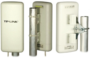
- Настройка наружной точки доступа TP-LINK TL-WA5210G
Если перед вами стоит задача, подключить Интернет на большом расстоянии (до 3 км –проверенно практически), то идеально подойдёт точка доступа TP-LINK TL-WA5210G, разумное сочетание цены и качества.
Внешний вид и метод крепления TL-WA5210G
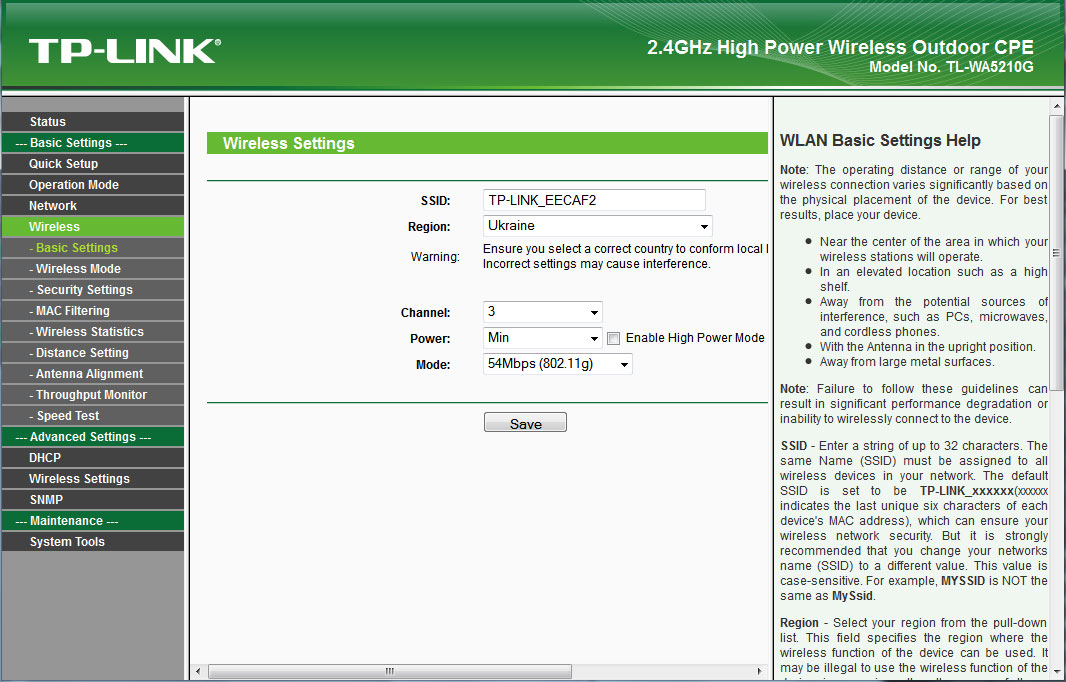
WEB интерфейс точки

Настройка TP-LINK TL-WA5210G как точки доступа
После несложного подключения точки доступа, нам нужно её настроить. Для того, что бы настроить их нужно выполнить несколько действий:
— Необходимо вручную задать IP адрес своей сетевой плате – например 192.168.1.5;
— Набираем в адресной строке 192.168.1.254 и попадаем на страницу авторизации точки доступа WEB интерфейс, вводим стандартный логин и пароль – admin и admin;
— Приступаем к настройке, для начала сменим пароль в System Tools => Password;
— В Operation Mode должно быть выбрано AP: Access Point;
— Далее следуем в Network => LAN и копируем MAC Address (с сохранением скажем в текстовый документ), потом узнаете зачем, см. в настройке клиента;
— Теперь проследуем в Wireless => Basic Settings и в позиции Region выберем свою страну;
— Проверяем в Wireless => Wireless Mode должно быть выбрано Access Point;
— В разделе Wireless => Distance Setting выставляем расстояние, при котором будет использоваться канал.
Ну, вот пожалуй и всё, точка доступа настроена, теперь приступим к настройке клиента.
Настройка TP-LINK TL-WA5210G как клиента
Подключаем точку доступа по той же схеме, и приступаем к настройке:
— Оставляем IP адрес своего адаптера, (192.168.1.5);
— Набираем в адресной строке 192.168.1.254 и попадаем на страницу авторизации точки доступа, вводим стандартный логин и пароль – admin и admin;
— Меняем пароль в ТД как при прошлой настройке;
— В Operation Mode выбираем AP Client Router: WISP Client Router;
— Далее следуем в Network => LAN и меняем IP адрес на 192.168.1.253, или с любым окончанием отличным от 192.168.1.254 (для удобства);
— Теперь проследуем в Wireless => Basic Settings и в позиции Region выберем свою страну; — Проследуем в Wireless => Wireless Mode и выбираем Client, потом выбираем пункт MAC of AP, теперь вставляем в строку MAC of AP: MAC адрес, который мы скопировали при настройке первой точки доступа;
— В разделе Wireless => Distance Setting выставляем расстояние, при котором будет использоваться канал;
— IP адрес и DNS сетевой платы нужно установить в получение автоматом, так как у точки доступа включился DHCP сервер после установки в Operation Mode => AP Client Router: WISP Client Router.
Теперь, вы сможете получить доступ ко внешним ресурсам (за AP), поднять VPN и PPPoE соединение или что либо.
Для функционирования доступа к ресурсам за AP, за AP должен быть поднят DHCP сервер (например провайдера), или нужно настроить IP адрес WAN клиентской точки доступа (Network => WAN => WAN Connection Type: Static IP), IP адрес, подходящий для внешней сети (естественно).
Остальные настройки уж на ваше усмотрение (например MAC фильтрация или шифрование).
В обзоре беспроводной точки доступа TP-Link 5210G мы уже познакомились с возможностями этого устройства, а в этой статье, мы рассмотрим пару основных варианта применения двух таких точек, для создания дальнего беспроводного соединения. Случаев, когда такое соединение может быть востребовано, огромное количество. Например для подключения к вашей сети удаленного от вашего офиса на какое-то расстояние склада, или для объединения двух офисов в разных зданиях, одним словом, там где не целесообразно тянуть кабель. При этом, бюджет не сильно большой, и нет потребности в высокопроизводительной сети с большой пропускной способностью.

И так, для всех описанных ниже соединений, нам потребуется две беспроводные точки доступа TP-Link 5210G.
Вариант№1
Начнем с первого варианта, который все ошибочно называют точка-точка, хотя на самом деле, оно таковым не является. Это обычное соединение, где есть головная станция (точка доступа) и есть клиент, а может быть и много клиентов. Хотя, это соединение может быть полностью прозрачным и использоваться для управления сетью с обеих сторон. Именно поэтому многие и ошибаются.
В этом варианте, возможна раздача IP адресов и маршрутизация, как средствами вашего роутера, так и средствами самой точки доступа TP-Link 5210G.
Первое устройство, настраивается как точка доступа. Для этого мы подключаем его к компьютеру, и заходим в web-интерфейс при помощи браузера. По умолчанию IP адрес точки доступа TP-Link 5210G — 192.168.1.254, а логин и пароль администратора — admin/admin.
Так как точка доступа не имеет встроенного DHCP клиента, то первым делом, мы должны присвоить ей другой IP адрес, если ваша сеть отличная от 192.168.1.0/24 или если адрес 192.168.1.254 уже занят другим устройством.
Для этого переходим в раздел Network и вписываем в поле IP Address: новый адрес, в поле Subnet Mask: маску подсети и в поле Gateway: адрес вашего маншрутизатора.

Теперь нам надо сохранить настройки нажатием кнопки Save и перейти в раздел Operation Mode, где выбрать режим работы — AP: Access Point.

После сохранения настроек (кнопка Save), мы перемещаемся в раздел Wireless — Basic Settings. Где в поле SSID: мы указываем идентификатор нашей точки доступа. В поле Region:, мы должны выбрать нашу страну. А в поле Channel: — канал на котором будет устанавливаться наше соединение. Power:, выбираем в зависимости от расстояния, на которое надо установить соединение. Само собой, чем больше расстояние, тем выше должны быть мощность. Однако не стоит забывать, что на высокой мощности, не возможно добиться высоких скоростей, поэтому выставляете этот параметр, соизмеримо в необходимостью. Галочка рядом с Enable High Power Mode включает режим повышенной мощности. И параметр для поля Mode:, мы выбираем 54Mbps (802.11g), для более скоростного соединения.

Следующим шагом, будут настройки в разделе Wireless — Wireless Mode, где мы должны выбрать режим Access Point. При этом, если мы не хотим, чтобы наш SSID транслировался, мы можем убрать галочку рядом с Enable SSID Broadcast.

Сохранив настройки, переходим в раздел Wireless — Security Settings. Здесь выбираем тип шифрования WPA-PSK/WPA2-PSK. И соответственно в полях для этого шифрования указываем… Version: — WPA2-PSK, Encryption: — AES, и PSK Passphrase: — указываем ключ шифрования.

После сохранения настроек кнопкой Save, настройку базовой точки доступа, можно считать оконченной.
Теперь приступим к настройке клиента.
Как и в случае с первым устройством, второе нам так же надо подключить к компьютеру и первым делом сменить IP адрес в разделе Network, чтобы он отличался от адреса точки доступа.

Сохраняем настройки и переходим в раздел Operation Mode, где как и в первом случае, выбрать режим работы — AP: Access Point.
И продолжаем настройку, уже в разделе Wireless — Basic Settings. Где поле SSID: мы не трогаем. В поле Region:, мы должны выбрать нашу страну. А в полях Channel: и Power: — те же значения, что и в первой точке доступа. И параметр для поля Mode:, мы выбираем 54Mbps (802.11g), для более скоростного соединения.
Сохраняем настройки кнопкой Save и переходим в раздел Wireless — Wireless Mode. Здесь мы выбираем режим работы Client. Галочка установленная возле Enable WDS, позволит второму устройству, работать в качестве беспроводной точки доступа, и расширить вашу сеть не только для проводных устройств подключенных к Ethernet порту, но и для беспроводных клиентов. В поле SSID: мы вписываем идентификатор нашей базовой станции. Соединение можно так же осуществлять по MAC адресу, для этого выберите пункт MAC of AP: и впишите в это поле MAC адрес первой точки доступа.

И последним действием, будет настройка шифрования. Она так же должна полностью совпадать с настройками первого устройства.
Сохранив все настройки, мы можем включать оба устройства. Если все сделано правильно, они должны соединиться между собой. При этом на клиентском устройстве, светодиодная шкала, должна указывать на уровень принимаемого сигнала.

Вариант №2
Это и есть то самое настоящее соединение по типу точка-точка. Оно будет действительно только для двух устройств, идентифицирующих друг друга по MAC адресу. Оно полностью прозрачно. Для простоты понимая — это полный аналог кабеля идущего из точки А в точку Б, только вместо коннекторов, на концах этого соединения сами устройства TP-Link 5210G. Это соединение не будет видно никаким другим компьютерам или устройствам, в отличии от варианта №1.
Для настройки TP-Link 5210G в режиме Bridge (Point to Point) сначала подключаем наше устройство к компьютеру, и заходим в web-интерфейс при помощи браузера. По умолчанию IP адрес точки доступа TP-Link 5210G — 192.168.1.254, а логин и пароль администратора — admin/admin.
Так как точка доступа не имеет встроенного DHCP клиента для этого типа соединения, то первым делом, мы должны присвоить ей другой IP адрес, если ваша сеть отличная от 192.168.1.0/24 или если адрес 192.168.1.254 уже занят другим устройством.
Для этого переходим в раздел Network и вписываем в поле IP Address: новый адрес, в поле Subnet Mask: маску подсети и в поле Gateway: адрес вашего маншрутизатора.

Сохраняем настройки нажатием кнопки Save. При этом, не маловажным будет записать MAC адрес этого устройства. Он нам пригодится в дальнейшем.
Теперь нам надо перейти в раздел Operation Mode, где выбрать режим работы — AP: Access Point.

Сохраняем настройки нажатием кнопки Save.
И переходим в раздел Wireless — Basic Settings. Здесь поле SSID: нас мало интересует. В поле Region:, мы должны выбрать нашу страну. В поле Channel: мы выбираем канал на котором будет устанавливаться наше соединение. Power:, выбираем в зависимости от расстояния, но которое надо установить соединение. Само собой, чем больше расстояние, тем выше должны быть мощность. Однако не стоит забывать, что на высокой мощности, не возможно добиться высоких скоростей, поэтому выставляете этот параметр, соизмеримо в необходимостью. Галочка рядом с Enable High Power Mode включает режим повышенной мощности. И наконец, параметр для поля Mode:, мы выбираем 54Mbps (802.11g), для более скоростного соединения.

Сохраняем настройки нажатием кнопки Save. И переходим в раздел Wireless — Wireless Mode, где выбираем режим Bridge (Point to Point). При этом не ставим галочку рядом с With AP Mode, потому как в в противном случае, наше устройство будет работать еще и в режиме точки доступа. А в поле MAC of AP: мы вписываем MAC адрес второго устройства. Его можно узнать на наклейке на самом устройстве, или подключив второе устройство к компьютеру и посмотрев его в web-интерфейсе.

Как и во всех других случаях, сохраняем сделанные настройки нажатием кнопки Save.
Настройка второго устройства производится точно так же, за исключением того, что мы должны назначить ему IP адрес в разделе Network, отличный от IP адреса первого устройства. А в разделе Wireless — Wireless Mode, при выборе режима Bridge (Point to Point), в поле MAC of AP указать MAC адрес первого устройства, который я говорил, записать.
Далее, мы устанавливаем и включаем обе точки, и если все настройки произведены правильно, то они должны соединиться. Узнать об этом можно в разделе Status. Где в информации беспроводного соединения, в графе Signal:, мы должны видеть уровень сигнала противоположной точки доступа. Если соединения нет, то эта графа, будет пустой.
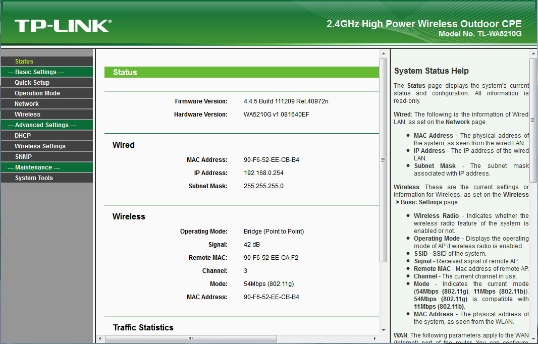
Проверить соединение можно так же при помощи пинга IP адреса удаленного устройства.

Проверка скорости соединения
И последнее, что хотелось бы сделать, это конечно же, проверить скорость нашего соединения. Для этого в программном обеспечении TP-Link 5210G есть специальная утилита. Находится она в разделе Wireless и называется Speed Test.
Открыв ее, мы должны указать IP адрес удаленного устройства (второй точки доступа) в поле Destination IP:. А в полях User: и Password:, соответственно логин и пароль, для администрирования второго устройства. Через некоторое время, после нажатия кнопки Run Test, мы должны увидеть результаты передачи данных в графе Tx: и приема данных в графе Rx:.

Как мы видим выше, в нашем случае, результаты составили порядка 20Mbit/s реальной скорости, что полностью соответствует стандарту 802.11g и скорости соединения в 54Mbit/s.
Алексей С., специально для LanMarket
Раздел: Сети, связь, телекоммуникации, интернет, безопасность
Тип: Точка Доступа
Характеристики, спецификации
Стандарт беспроводной связи:
802.11g
Максимальная скорость беспроводного соединения:
54 Мбит/с
Защита информации:
WEP, WPA, WPA2
Функция «Режим моста»:
есть
Межсетевой экран (FireWall):
есть
Встроенный «DHCP Сервер»:
есть
Демилитаризованная зона (DMZ):
есть
Статическая маршрутизация:
есть
Поддержка технологии «VPN pass through»:
есть
Количество внутренних антенн:
1 x 12 dBi
Наличие «Web-интерфейса»:
есть
Поддержка технологии «SNMP»:
есть
Power over Ethernet (PoE):
есть
Возможность установки вне помещения:
есть
Размеры (ШxВxГ):
265x83x120 мм
Инструкция к Точке Доступа Tp-Link TL-WA5210G
Установка
1
Подключение устройства
Внимание
Для настройки точки доступа следует использовать только проводное
подключение.
Выберите подходящее место для установки вашего клиентского
оборудования. Для достижения наилучшего результата установку
рекомендуется производить как можно выше в местах, обеспечивающих
связь с пользователями в зоне прямой видимости и расположенных над
деревьями, зданиями и крупными металлическими конструкциями,
которые выступают в качестве препятствия и снижают качество сигнала
антенны.
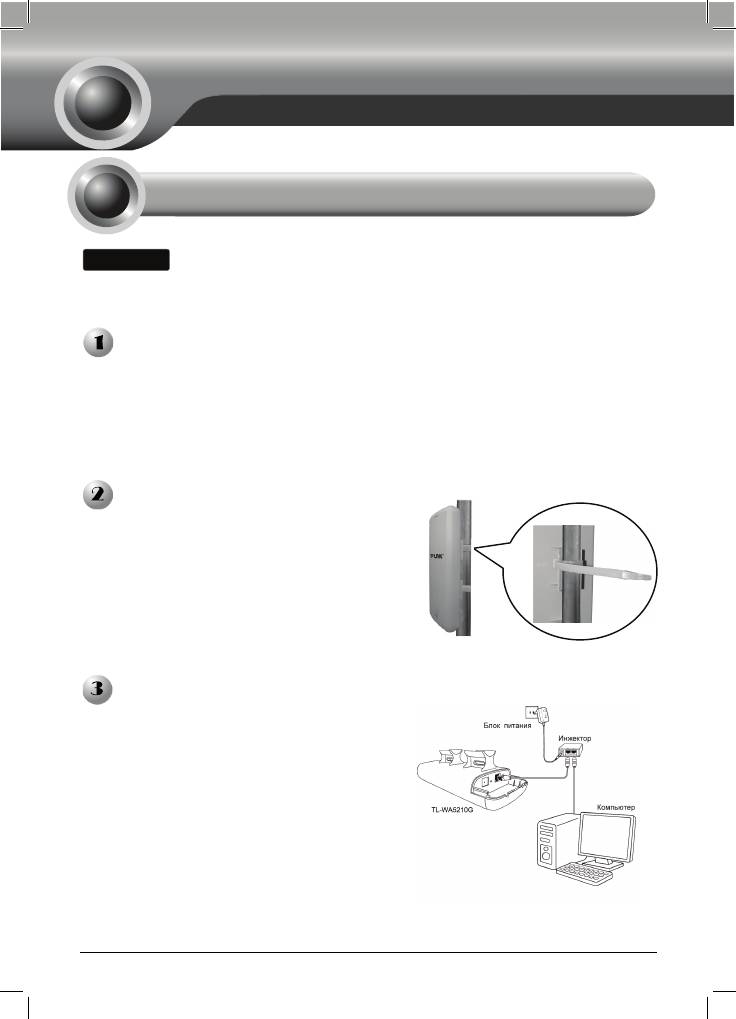
Для достижения наилучшего качества
сигнала отрегулируйте направление и
ориентацию вашего клиентского
оборудования. Проденьте ремешки
через специальное отверстие в задней
части клиентского оборудования и
обвяжите их вокруг столба, на который
производится установка. Затяните
застежки на ремешках.
Подключите один конец сетевого кабеля
Ethernet к порту POE поставляемого
вкомплекте инжектора питания, а другой
конец кабеля Ethernet к порту LAN на
клиентском оборудовании. Затем
подключите порт LAN инжектора
питания к ПК с помощью другого кабеля
Ethernet. В завершение, подключите
поставляемый в комплекте блок питания
к разъему DC на инжекторе питания и
сам блок питания подсоедините к
стандартной эл
ектрической розетке.
1
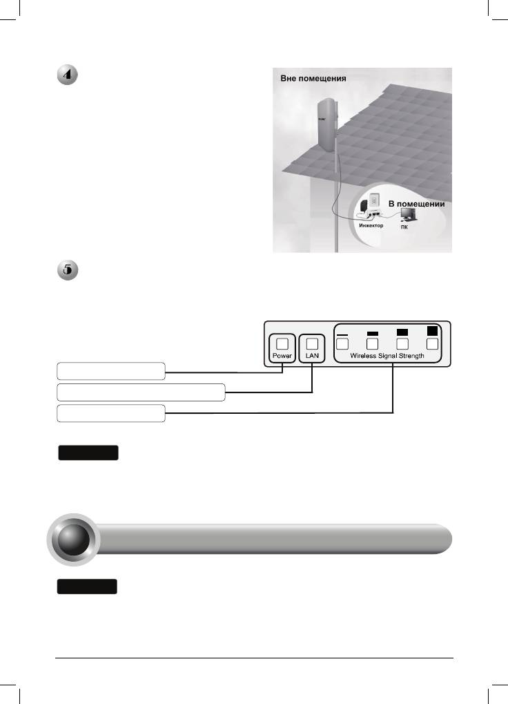
После выполнения перечиленных
выше операций должна получиться
представленой на рисунке.
Включите все ваши сетевые устройства и затем удостоверьтесь, что
светодиодные индикаторы на точке доступа указывают на работу в
нормальном режиме в соответствии с приведённым ниже рисунком.
Внимание
Если светодиодные индикаторы горят не так, как показано на рисунке,
пожалуйста, проверьте правильность подключения проводов к устройству (блок
питания и сетевой кабель Ethernet).
Вашему компьютеру необходимо присвоить Статический IP-адрес в пределах
диапазона IP-адресов точки доступа. Смотрите раздел Устранение
н
2
е
и
с
п
ра
вн
ос
т
е
й T
3,
ес
ли в
а
м н
еоб
х
од
им
а
п
о
м
ощ
Горит постоянно
Горит постоянно или мигает
Горит постоянно
2
Настройка оборудования
Внимание
ь.
Вход в Систему
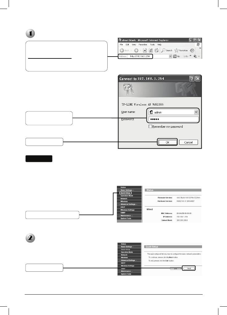
На экране появится диалоговое окно,
в котором необходимо ввести имя
пользователя User name и пароль
Password. Введите значения,
установленные по умолчанию, и
нажмите OK.
Внимание
Если диалоговое окно не появляется, воспользуйтесь подсказками раздела T3
в разделе Устранение неисправностей. Используйте раздел T2 в случае,
если вы забыли па
Настройка рабочего режима
3
р
Откройте Ваш браузер, введите в
адресную строку
http://192.168.1.254
и нажмите
клавишу Enter для
подтверждения ввода
User name: admin
Password: admin
Нажмите OK
оль.
После успешного вхождения в систему
на экране отобразится страница
управления через веб—интерфейс.
Нажмите Quick Setup
Отобразится следующая страница.
Нажмите Next
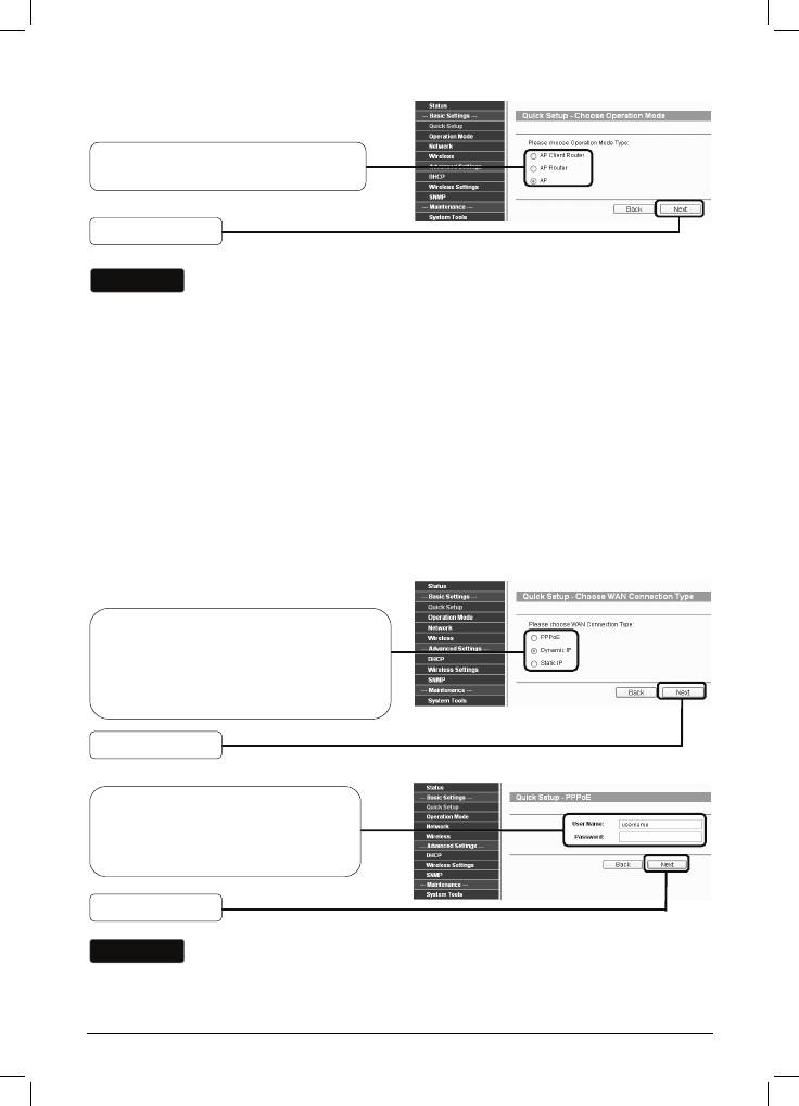
Выберите нужный тип рабочего
режима Operation Mode Type
Нажмите Next
Внимание
Точка доступа поддерживает три рабочих режима: AP Client Router
(клиентская точка доступа), AP Router (точка доступа с маршрутизатором)
и AP (точка доступа).
a) Если вы хотите подключиться к вашему поставщику Интернет—услуг, то
следует выбрать режим AP Client Router и перейти к подразделу A;
b) Если вы хотите настроить подключение «точка—точка», то вам следует
перейт
и к подразделу B;
c) Если вы хотите настроить режим ретрансляции, то вам следует перейти к
подразделу C.
A. Настройка клиента поставщика Интернет—услуг (Клиентское
оборудование)
Отобразится следующая страница.
Выберите тип подключения WAN
Connection Type
предоставляемый вашим
поставщиком Интернет—улуг. Здесь
в качестве примера выбран PPPoE
Нажмите Next
Введите имя пользователя
Username и пароль Password,
предоставленные вашим
поставщиком Интернет—услуг
Нажмите Next
Внимание
Имя пользователя Username и пароль Password предоставляются вашим
поставщиком Интернет—услуг.
4
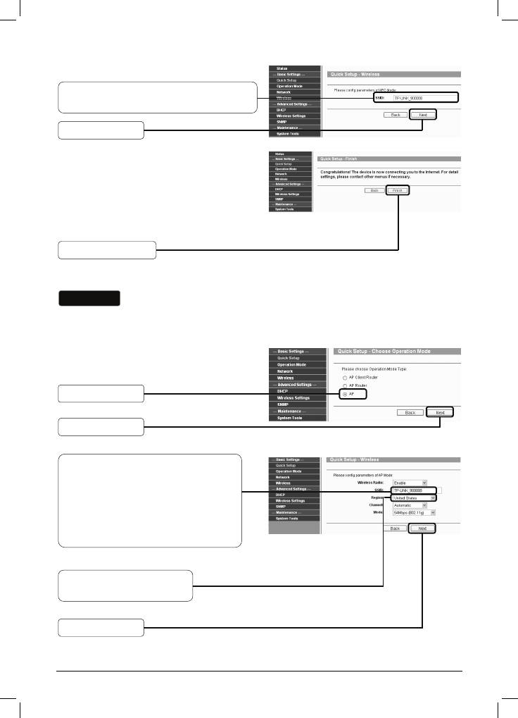
Введите имя SSID, предоставленное
вашим поставщиком Интернет—услуг
Нажмите Next
Нажмите Finish для выхода из
Мастера быстрой настройки Quick
Setup и подождите, пока точка
доступа автоматически
перезагрузится. Изменения вступят в
силу после перезагрузки.
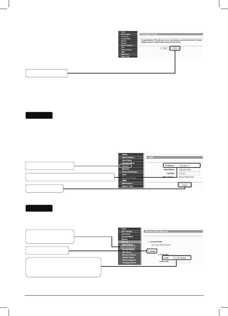
Нажмите Finish
B. Настройка подключения «точка—точка»
Внимание
Для данного типа подключения необходимы две точки доступа TL-WA5210G.
1) Настройка точки доступа
Выберите AP
Нажмите Next
Введите уникальное имя вашей
беспроводной сети;
рекомендуется задавать имена,
которые смогут с легкостью
запомнить все пользователи
сети. Здесь в качестве примера
SSID введено TP-LINK_900008
Из выпадающего списка
выберите ваш регион
Нажмите Next
5
Нажмите Finish для выхода из
Мастера быстрой настройки Quick
Setup и подождите, пока Точка
доступа автоматически
перезагрузится. Изменения вступят в
силу после перезагрузки.
Нажмите Finish
После успешного входа в систему произведите настройку второго
TL-WA5210G, выполняя указанные ниже пошаговые операции.
2) Настройка клиента
Внимание
Необходимо изменить установленный по умолчанию LAN IP-адрес клиента с
192.168.1.254 на 192.168.1.X (где X может быть любая цифра от 2 до 253) для
того, чтобы исключить конфликт IP-адресов с предыдущей точкой доступа. В
данном случае в качестве примера выбран 192.168.1.2.
Нажмите Network
Введите 192.168.1.2 в поле IP —адреса
Нажмите Save
Внимание
После нажатия кнопки Save точка доступа начнет автоматическую
перезагрузку.
Нажмите Wireless
> Wireless Mode
Выберите Client
Введите TP-LINK_900008, имя
SSID первой точки доступа,
которую вы уже настроили
Нажмите Save в нижней части этой страницы для сохранения.
6
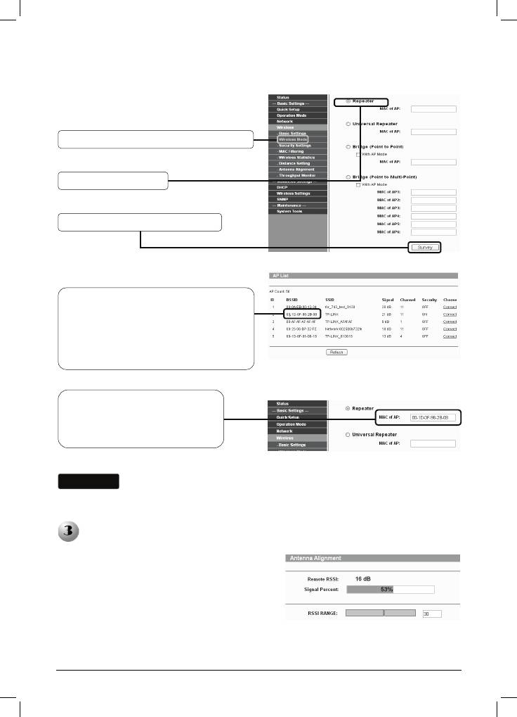
C. Настройка режима ретранслятор
Нажмите Wireless > Wireless Mode
Выберите Repeater
Нажмите Survey для поиска
Отобразится следующая страница.
Отыщите имя BSSID удаленной
Точки доступа, которую Вы хотите
ретранслировать, и выпишите его
или скопируйте. Здесь мы копируем
BSSID точки доступа TP-LINK:
00-1D-DF-98-2B-08
Введите или вставьте из
буфера имя BSSID удаленной
Точки доступа в поле под
надписью Repeater
Внимание
Имя BSSID совпадает с MAC-адресом
Нажмите Save в нижней части этой страницы для сохранения.
Регулировка ориентации антенны
После базовой настройки рабочего режима
для улучшения качества и мощности
сигнала вы можете изменить направление
ориентации вашего клиентского
оборудования в соответствии с
инструкциями, которые представлены на
странице регулировки ориентации
антенны.
7
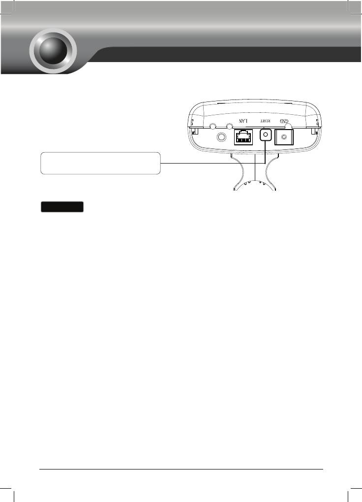
Устранение неисправностей
T1. Каким образом я могу произвести сброс настроек точки доступа до
заводских?
При включенной точке доступа
нажмите и удерживайте кнопку RESET
на задней панели устройства в течение
8-10 секунд.
Нажмите ее и удерживайте
нажатой в течение 8-10 секунд
Внимание
После сброса настроек точки доступа тек
ущие настройки будут потеряны, и
вам потребуется произвести настройку оборудования заново.
T2. Что делать, если я забыл пароль?
1) Произведите сброс настроек точки доступа до заводских параметров. Если
вы не знаете, каким образом производится сброс настроек, ознакомьтесь с
предыдущим разделом T1;
2) Используйте имя пользователя и пароль по умолчанию: admin, admin;
3) Попробуйте произвести повторную настройку вашей точки доступа, следуя
инструкциям п
редыдущих шагов настоящего Руководства по быстрой
установке.
T3. Что мне делать, если я не могу попасть на страницу настроек на
основе веб—интерфейса?
1) Настройте IP-адрес вашего компьютера.
8
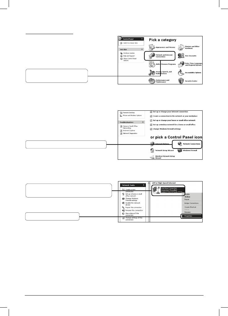
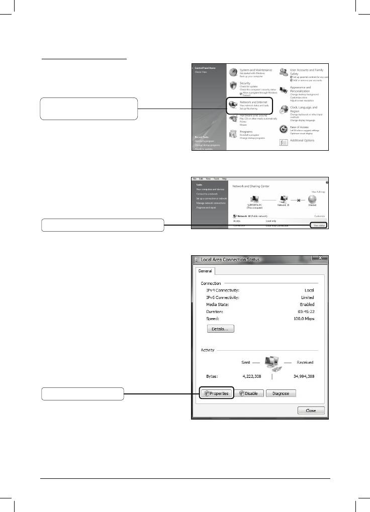
Для ОС Windows XP
Выберите Пуск > Панель
управления, отобразится
следующая страница.
Выберите Сеть и
подключение Интернет
Нажмите Сетевые подключения
Нажмите правой кнопкой на
Подключение по локальной сети
Выберите Свойства
9
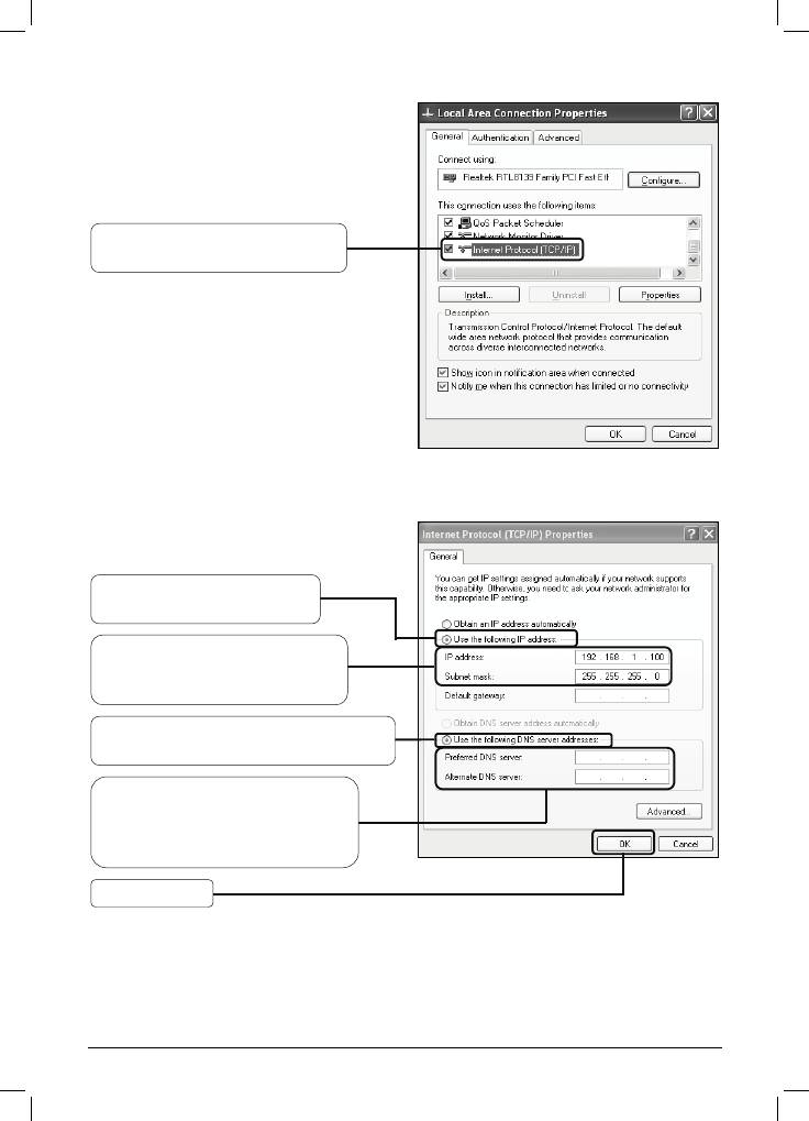
Двойной щелчок на Протокол
Интернета (TCP
Выберите Использовать
следующий IP-адрес
Введите 192.168.1.100 в поле
IP-адреса, 255.255.255.0 в
поле маски подсети
Выберите Использовать
следующие адреса DNS-серверов
Введите Адрес DNS-сервера,
предоставленный вам вашим
поставщиком Интернет—услуг
или сетевым администратором
Нажмите OK
10
/
IP)
Для ОС Windows Vista
Выберите Пуск > Настройки >
Панель управления,
отобразится следующая
Нажмите Просмотр
состояния сети и задач
Нажмите Просмотр состояния
Выберите Свойства
11
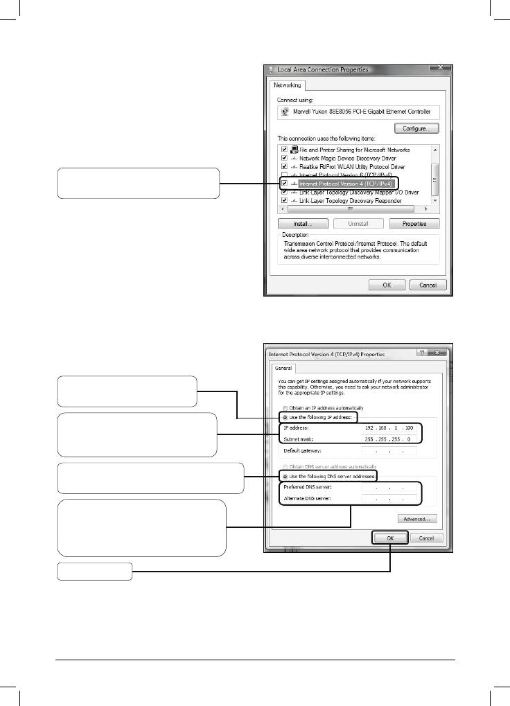
Двойной щелчок на Протокол
Интернета 4 (TCP
Выберите Использовать
следующие адреса
DNS-серверов
Введите Адрес DNS-сервера,
предоставленный вам вашим
поставщиком Интернет—услуг
или сетевым администратором
Нажмите OK
12
/
IP
v
4)
Выберите Использовать
следующий IP-адрес
Введите 192.168.1.100 в поле
IP-адреса, 255.255.255.0 в
поле маски подсети
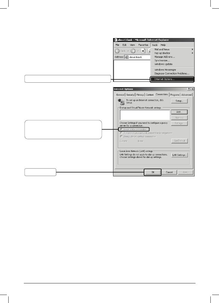
2) Настройка вашего браузера IE.
Откройте окно вашего браузера
IE, нажмите вкладку Сервис и
появится следующее меню.
Выберите Свойства обозревателя…
Выберите Никогда не
использовать коммутируемые
подключения
Нажмите OK
После применения указанных изменений попробуйте войти на страницу
настройки через веб—интерфейс ещё раз. Если вы по—прежнему не можете
войти на страницу настроек, произведите сброс настроек точки доступа до
заводских и произведите перенастройку точки доступа, следуя инструкциям
данного Руководства по быстрой установке в разделе Т1. При сохранении
проблемы свяжи
тесь с нашей Службой технической поддержки.
13

ТЕХНИЧЕСКАЯ ПОДДЕРЖКА
Для выявления и устранения неисправностей:
www.tp-link.com/support/faq.asp
Для загрузки последних прошивок, драйверов, утилит и руководств пользователя:
www.tp-link.com/support/download.asp
По другим вопросам технической поддержки, свяжитесь с нами, используя
следующую контактную информацию:
Глобальная служба
Австралия и Новая Зеландия
Тел.: +86 755 26504400
Тел.: 1300 87 5465 (Австралия)
E-mail: support@tp-link.com
0800 87 5465 (Новая Зеландия)
Режим работы: круглосуточно, без
E-mail: support@tp-link.com.au
выходных
Режим работы: круглосуточно, без
выходных
Сингапур
Малайзия
Тел.: +65 62840493
Тел.: 1300 88 875465 (1300 88TPLINK)
E-mail: support.sg@tp-link.com
Email: support.my@tp-link.com
Режим работы: круглосуточно, без
Ре
жим работы: круглосуточно, без
выходных
выходных
Великобритания
Турция
Тел.: +44 (0) 845 147 0017
Тел.: 444 19 25DŽТурецкая службаDž
E-mail: support.uk@tp-link.com
E-mail: support.tr@tp-link.com
Ре
жим работы: круглосуточно, без
Режим работы: 9:00 AM to 6:00 PM,
выходных
без выходных
США/Канада
Италия
Тел.: +1 866 225 8139 (бесплатно)
Тел.: +39 02 66987799
E-mail: support.usa@tp-link.com
E-mail: support.it@tp-link.com
Режим работы: круглосуточно, без
Режим работы: с 9:00 до 18:00, с
выходных
понедельника по пятницу
Германия / Австрия
Швейцария
Тел.: +49 1805 875465 (Немецкая
Тел.: +41 (0)848 800998 (Немецкая
служба) / +49 1805 TPLINK
служба)
E-mail: support.de@tp-link.com
E-mail: support.ch@tp-link.com
Тариф: 0
,14 евро/мин со
Тариф: 4-8 рап/мин в зависимости от
стационарных телефонов в
тарифов в разное время
Германии и до 0,42 евро/мин с
Режим работы: с понедельника по
мобильных телефонов
пятницу, с 9:00 до 18:00. Часовой пояс
Режим работы: с понедельника по
GMT+1 или GMT+2 (в летнее время)
пятницу, с 9:00 до 18:00. Часовой
пояс GMT+ 1 or GMT+ 2 (в летнее
время)
*За исключением банковских
праздников в Гессене.
Аннотация для Точки Доступа Tp-Link TL-WA5210G в формате PDF
Топ 10 инструкций
Другие инструкции
-
Page 1
TL-WA5210G 2.4GHz High Power Wireless Outdoor CPE Rev: 1.0.0 1910010274… -
Page 2
Specifications are subject to change without notice. is a registered trademark of TP-LINK TECHNOLOGIES CO., LTD. Other brands and product names are trademarks or registered trademarks of their respective holders. No part of the specifications may be reproduced in any form or by any means or used to make any derivative such as translation, transformation, or adaptation without permission from TP-LINK TECHNOLOGIES CO., LTD. -
Page 3: Fcc Statement
FCC STATEMENT This equipment has been tested and found to comply with the limits for a Class B digital device, pursuant to part 15 of the FCC Rules. These limits are designed to provide reasonable protection against harmful interference in a residential installation. This equipment generates, uses and can radiate radio frequency energy and, if not installed and used in accordance with the instructions, may cause harmful interference to radio communications.
-
Page 4
National Restrictions 2400.0-2483.5 MHz Country Restriction Reason/remark General authorization required for outdoor use Bulgaria and public service Military Radiolocation use. Refarming of the 2.4 Outdoor use limited to 10 GHz band has been ongoing in recent years to France mW e.i.r.p. within the allow current relaxed… -
Page 5: Declaration Of Conformity
TP-LINK TECHNOLOGIES CO., LTD DECLARATION OF CONFORMITY For the following equipment: Product Description: 2.4GHz High Power Wireless Outdoor CPE Model No.: TL-WA5210G Trademark: TP-LINK We declare under our own responsibility that the above products satisfy all the technical regulations applicable to the product within the scope of Council Directives:…
-
Page 6: Table Of Contents
CONTENTS Package Contents ……………………..1 Chapter 1 Product Overview………………….2 Overview of the Product………………….2 Features ……………………… 2 Conventions ……………………..3 Chapter 2 Hardware Installation …………………4 LED Explanation ……………………4 Interfaces and button ………………….. 4 System Requirements………………….5 Environment Requirements …………………5 Connecting the Device………………….
-
Page 7
Wireless settings……………………35 Forwarding ……………………..36 4.9.1 Virtual Servers……………………37 4.9.2 Port Triggering……………………38 4.9.3 DMZ……………………..40 4.9.4 UPnP ……………………..41 4.10 Security ……………………..41 4.10.1 Firewall ………………………42 4.10.2 IP Address Filtering ………………….43 4.10.3 Domain Filtering ………………….44 4.10.4 MAC Address Filtering ………………..46 4.10.5 Remote Management…………………47 4.10.6 Advanced Security ………………….48 4.11 Static Routing…………………….50 4.12… -
Page 8
Quick Setup ………………………68 Operation Mode ……………………69 Network ……………………..69 Wireless ……………………..70 5.6.1 Basic Settings…………………….70 5.6.2 Wireless Mode……………………72 5.6.3 Security Settings ………………….76 5.6.4 MAC Filtering……………………79 5.6.5 Wireless Statistics ………………….81 5.6.6 Distance Setting ………………….82 5.6.7 Antenna Alignment ………………….82 5.6.8 Throughput Monitor ………………….83 DHCP ………………………..83 5.7.1 DHCP Settings …………………..84 5.7.2… -
Page 9: Package Contents
One power Adapter for TL-WA5210G 2.4GHz High Power Wireless Outdoor CPE One Power Injector Mounting Kits Quick Installation Guide One Resource CD for TL-WA5210G 2.4GHz High Power Wireless Outdoor CPE, including: This User Guide Other helpful information Note: Make sure that the package contains the above items. If any of the listed items are damaged or…
-
Page 10: Chapter 1 Product Overview
The TL-WA5210G 2.4GHz High Power Wireless Outdoor CPE is dedicated to Outdoor wireless network solutions. The TL-WA5210G 2.4GHz High Power Wireless Outdoor CPE will allow you to connect your network with other wireless devices wirelessly, sharing Internet Access, files and fun, easily and securely.
-
Page 11: Conventions
Supports Web management. Conventions The AP or TL-WA5210G, or device mentioned in this User guide stands for TL-WA5210G 2.4GHz High Power Wireless Outdoor CPE without any explanations. Parameters provided in the pictures are just references for setting up the product, which may differ from the actual situation.
-
Page 12: Chapter 2 Hardware Installation
Chapter 2 Hardware Installation LED Explanation TL-WA5210G consists of several LED indicators, which is designed to indicate connections and wireless signal. Figure 2-1 Front Panel sketch View from left to right. Name Status Indication No Power Power Power on There is no device linked to the corresponding port…
-
Page 13: System Requirements
: This is where you can connect an outside antenna. For this AP, the antenna is built inside, and usually there is not necessary to connect an outside one. LAN: This port is used to connect to the POE port of the provided Power Injector. RESET: There are two ways to reset the AP’s factory defaults: •…
-
Page 14
Figure 2-3… -
Page 15: Chapter 3 Quick Installation Guide
The instructions in this section will help you configure each of your PCs to be able to communicate with the AP. The default IP address of the TL-WA5210G 2.4GHz High Power Wireless Outdoor CPE is 192.168.1.254. And the default Subnet Mask is 255.255.255.0. These values can be seen from the LAN.
-
Page 16: Quick Setup
Internet. With a Web-based (Internet Explorer or Netscape Navigator) utility, it is easy to configure and manage the TL-WA5210G 2.4GHz High Power Wireless Outdoor CPE. The Web-based utility can be used on any Windows, Macintosh or UNIX OS with a Web browser.
-
Page 17
Figure 3-4 Login Windows Note: If the above screen does not pop-up, it means that your Web-browser has been set to a proxy. Go to Tools menu>Internet Options>Connections>LAN Settings, in the screen that appears, cancel the Using Proxy checkbox, and click OK to finish it. If the User Name and Password are correct, you can configure the AP using the Web browser. -
Page 18
Note: The AP supports three mode operation modes for multi-user to access the Internet: AP Client Router, AP Router and AP. In AP Client Router mode, it can access the Internet wirelessly by your WISP’s support. In AP Router mode, it can access the Internet via ADSL/Cable Modem. In AP mode, it can access a wireless network by using WIFI. -
Page 19
Figure 3-9 Quick Setup — Static IP Note: The IP parameters should have been provided by your ISP. IP Address — This is the WAN IP address as seen by external users on the Internet (including your ISP). Enter the IP address into the field. Subnet Mask — The Subnet Mask is used for the WAN IP address, it is usually 255.255.255.0. -
Page 20
Figure 3-11 Quick Setup — Wireless settings SSID — Enter a value of up to 32 characters. The same SSID must be assigned to all wireless devices on your network. The default SSID is TP-LINK_XXXXXX This value is case-sensitive. For example, TEST is NOT the same as test. Region — Specifies the region where the wireless function of the AP can be used. -
Page 21: Chapter 4 Ap Client Router & Ap Router Operation Mode
Chapter 4 AP Client Router & AP Router Operation Mode This Chapter describes how to configure some advanced settings for your Access Point through the web-based management page. In the following explanations, we will take the device in AP Client Router operation mode for example. Login After your successful login, you can configure and manage the Access Point.
-
Page 22
Figure 4-1 Status This field displays the current settings or information for the LAN, including the MAC address, IP address and Subnet Mask. Wireless This field displays basic information or status for wireless function, including Wireless Radio, SSID, Channel, Mode, and Wireless MAC address. -
Page 23: Quick Setup
These parameters apply to the WAN port of the router, including MAC address, IP address, Subnet Mask, Default Gateway and DNS server. If PPPoE is chosen as the WAN connection type, the Disconnect button will be shown here while you are accessing the Internet. You can also cut the connection by clicking the button.
-
Page 24: Lan
detailed explanations for each submenu are provided below. Figure 4-3 the Network menu 4.5.1 Selecting Network > LAN will enable you to configure the IP parameters of LAN port on this page. Figure 4-4 LAN MAC Address — The physical address of the router, as seen from the LAN. The value can’t be changed.
-
Page 25
Figure 4-5 WAN – Dynamic IP This page displays the WAN IP parameters assigned dynamically by your ISP, including IP address, Subnet Mask, Default Gateway, etc. Click Renew to renew the IP parameters from your ISP. Click Release to release the IP parameters. MTU Size — The normal MTU (Maximum Transmission Unit) value for most Ethernet networks is 1500 Bytes. -
Page 26
Figure 4-6 WAN — Static IP You should type the following parameters into the spaces provided: IP Address — Enter the IP address in dotted-decimal notation provided by your ISP. Subnet Mask — Enter the subnet Mask in dotted-decimal notation provided by your ISP, usually is 255.255.255.0. -
Page 27
Figure 4-7 WAN — PPPoE User Name/Password — Enter the User Name and Password provided by your ISP. These fields are case-sensitive. Connect on Demand — You can configure the router to disconnect your Internet connection after a specified period of inactivity (Max Idle Time). If your Internet connection has been terminated due to inactivity, Connect on Demand enables the router to automatically re-establish your connection as soon as you attempt to access the Internet again. -
Page 28
field. Otherwise, enter the number time in minutes that you wish to have the Internet connecting last unless a new link is requested. Caution: Sometimes the connection cannot be disconnected although you specify a time to Max Idle Time, since some applications are visiting the Internet continually in the background. -
Page 29: Mac Clone
4.5.3 MAC Clone MAC Clone allows you to clone the MAC address of the managing PC’s adapter to the WAN port. This is because some ISPs require that you register the MAC address of your adapter. Usually, you do not need to change anything here. Selecting Network >…
-
Page 30: Basic Settings
Wireless Mode, Security Settings, MAC Filtering, Wireless Statistics, Distance Setting, Antenna Alignment and Throughput Monitor. Click any of them, and you will be able to configure the corresponding function. The detailed explanations for each submenu are provided below. Figure 4-10 Wireless menu 4.6.1 Basic Settings Selecting Wireless >…
-
Page 31: Wireless Mode
Note Dialog Note: Limited by local law regulations, version for North America does not have region selection option. This field determines which operating frequency will be used. It is not necessary to Channel — change the wireless channel unless you notice interference problems with another nearby access point.
-
Page 32
Figure 4-12 Wireless Mode Note: In AP Client Router, there is only Client mode available shown as Figure 4-12 while in AP Router there is only Access Point mode available. Access Point — Access Point mode allows wireless stations including AP clients to access the router. -
Page 33
• Enable SSID Broadcast — If you select the Enable SSID Broadcast checkbox, the Wireless AP will broadcast its name (SSID) on the air. Client — In Client mode, AP will act as a wireless station to enable wired host(s) to access wireless AP. -
Page 34: Security Settings
4.6.3 Security Settings Selecting Wireless > Security Settings will enable you to configure the security of the wireless network for your device on the page as shown in Figure 4-14. Figure 4-14 Wireless Security Disable Security — The wireless security function can be enabled or disabled. If disabled, the wireless stations will be able to connect the device without encryption.
-
Page 35
Open System — Select 802.11 Open System authentication. • WEP Key Format — You can select ASCII or Hexadecimal format. ASCII format stands for any combination of keyboard characters in the specified length. Hexadecimal format stands for any combination of hexadecimal digits (0-9, a-f, A-F) in the specified length. •… -
Page 36: Mac Filtering
value can be either 0 or at least 30. Enter 0 to disable the update. Be sure to click the Save button to save your settings on this page. Note: The device will reboot automatically after you click the Save button. 4.6.4 MAC Filtering Selecting Wireless >…
-
Page 37
Figure 4-16 Add or Modify Wireless MAC Address Filtering entry To add or modify a MAC Address Filtering entry, follow these instructions: Enter the appropriate MAC Address into the MAC Address field. The format of the MAC Address XX-XX-XX-XX-XX-XX hexadecimal digit). -
Page 38: Wireless Statistics
5. Click the Add New… button and enter the MAC address 00-0A-EB-00-07-5F in the MAC Address field, enter wireless station B in the Description field, select Deny in the Privilege pull-down list and select Enabled in the Status pull-down list. Click the Save and the Return button.
-
Page 39: Antenna Alignment
conditions as shown in Figure 4-18. This is a critical feature required for stabilizing outdoor links. Enter the distance of your wireless link and the software will optimize the frame ACK timeout value automatically. Figure 4-18 Distance Setting Adjust option — Keep the default setting if the AP is used for outdoor environment. Or you can change the distance manually.
-
Page 40: Throughput Monitor
4.6.8 Throughput Monitor Selecting Wireless > Throughput Monitor will helps to watch wireless throughput information in the following screen shown in Figure 4-20. Figure 4-20 Wireless Throughput Rate — The Throughput unit. Run Time — How long this function is running. Transmit- Wireless transmit rate information.
-
Page 41: Dhcp Settings
Figure 4-21 The DHCP menu 4.7.1 DHCP Settings Selecting DHCP > DHCP Settings will enable you to set up the AP as a DHCP (Dynamic Host Configuration Protocol) server, which provides the TCP/IP configuration for all the PCs that are connected to the system on the LAN.
-
Page 42: Dhcp Clients List
provides two DNS servers. The factory default setting is 0.0.0.0. Click Save to save the changes. Note: To use the DHCP server function of the device, you should configure all computers in the LAN as «Obtain an IP Address automatically» mode. This function will not take effect until the device reboots.
-
Page 43: Wireless Settings
MAC Address — Here displays the MAC address of the PC for which you want to reserve an IP address. Reserved IP Address — Here displays the IP address that the AP is reserved. Status — Here shows whether the entry is enabled or not Modify — To modify or delete an existing entry.
-
Page 44: Forwarding
Figure 4-26 Wireless settings Enable WMM — WMM function can guarantee the packets with high- priority messages being transmitted preferentially. It is strongly recommended enabled. Enable AP Isolation — Isolate all connected wireless stations so that wireless stations can not access each other through WLAN. This option is available only for AP mode. Disable short preamble — Disable short preamble and use long preamble only.
-
Page 45: Virtual Servers
require multiple connections. The DMZ host feature allows one local host to be exposed to the Internet for a special-purpose service such as Internet gaming or videoconferencing. DMZ host forwards all the ports at the same time. Any PC whose port is being forwarded must have its DHCP client function disabled and should have a new static IP Address assigned to it because its IP Address may change when using the DHCP function.
-
Page 46: Port Triggering
Select the Enable option to enable the virtual server. Click the Save button. Figure 4-29 Add or Modify a Virtual Server Entry Common Service Port — Some common services already exist in the pull-down list. Note: It is possible that you have a computer or server that has more than one type of available service. If so, select another service, and enter the same IP Address for that computer or server.
-
Page 47
Figure 4-30 Port Triggering Once configured, operation is as follows: A local host makes an outgoing connection to an external host using a destination port number defined in the Trigger Port field. The router records this connection, opens the incoming port or ports associated with this entry in the Port Triggering table, and associates them with the local host. -
Page 48: Dmz
Figure 4-31 Add or Modify a Triggering Entry To modify or delete an existing entry, please take the following steps: Click the Modify in the entry you want to modify. If you want to delete the entry, click the Delete. Modify the information.
-
Page 49: Upnp
Enter the IP address of a local PC that is desired to be set as the DMZ host in the DMZ Host IP Address field. Click the Save button. Note: After you set the DMZ host, the firewall related to the host will not work. 4.9.4 UPnP Selecting Forwarding >…
-
Page 50: Firewall
from a remote location via the Internet. There are six submenus under the Security menu (shown in Figure 4-34): Firewall, IP Address Filtering, Domain Filtering, MAC Address Filtering, Remote Management and Advanced Security. Click any of them, and you will be able to configure the corresponding function. The detailed explanations for each submenu are provided below.
-
Page 51: Ip Address Filtering
Enable MAC Filtering — Check this box to enable MAC Address Filtering. There are two default filtering rules for MAC Address Filtering: Allow or Deny the packets specified to pass through the router. 4.10.2 IP Address Filtering Selecting Security > IP Address Filtering will allow you to configure the IP address filtering entry on the page as shown in Figure 4-36.
-
Page 52: Domain Filtering
2. LAN IP Address — Enter a LAN IP Address or a range of LAN IP addresses in the field, in dotted-decimal notation format. For example, 192.168.1.20 — 192.168.1.30. Keep the field blank, which means all LAN IP Addresses have been put into the field. 3.
-
Page 53: Add/Modify Domain Filtering Entry
Figure 4-38 Domain Filtering Before adding a Domain Filtering entry, you must ensure that Enable Firewall and Enable Domain Filtering have been selected on the Firewall page as shown in Figure 4-35. To Add a Domain filtering entry, click the Add New… button in Figure 4-38. The page «Add or Modify a Domain Filtering entry»…
-
Page 54: Mac Address Filtering
Click the Disabled All button to make all entries disabled. Click the Delete All button to delete all entries Click the Next button to go to the next page and the Previous button to return to the previous page. For example, if you want to block the PC(s) on your LAN to access websites www.xxyy.com.cn, www.aabbcc.com and websites with .net…
-
Page 55: Remote Management
Figure 4-41 Add or Modify a MAC Address Filtering entry To add or modify a MAC Address Filtering entry, follow these instructions: Enter the appropriate MAC Address into the MAC Address field. The format of the MAC Address XX-XX-XX-XX-XX-XX hexadecimal digit).
-
Page 56: Advanced Security
from a remote location via the Internet. Figure 4-42 Remote Management Web Management Port — Web browser access normally uses the standard HTTP service port 80. This Router’s default remote management web port number is 80. For greater security, you can change the remote management web port to a custom port by entering that number in the box provided.
-
Page 57
Figure 4-43 Advanced Security settings Packets Statistic interval (5 ~ 60) — The default value is 10. Select a value between 5 and 60 seconds from the pull-down list. The Packets Statistic interval value indicates the time section of the packets statistic. The result of the statistic used for analysis by SYN Flood, UDP Flood and ICMP-Flood. -
Page 58: 4.11 Static Routing
router. Forbid Ping Packet from LAN Port — Enable or Disable forbidding Ping Packet to access the router from the LAN port. The default value is disabled. If enabled, the ping packet from the LAN port cannot access the router. (Defends against some viruses) Click the Save button to save the settings.
-
Page 59: 4.12 Ip & Mac Binding
Figure 4-45 Add or Modify a Static Route Entry To modify or delete an existing entry: Click the Modify in the entry you want to modify. If you want to delete the entry, click the Delete. Modify the information. Click the Save button. Click the Enable All button to make all entries enabled.
-
Page 60: Arp List
Figure 4-48 IP & MAC Binding Setting (Add & Modify) To add IP & MAC Binding entries, follow the steps below. Click the Add New… button as shown in Figure 4-62. Enter the MAC Address and IP Address. Select the Bind checkbox. Click the Save button to save it.
-
Page 61: 4.13 Dynamic Dns
Figure 4-50 ARP List MAC Address — The MAC address of the controlled computer in the LAN. IP Address — The assigned IP address of the controlled computer in the LAN. Status — Indicates whether or not the MAC and IP addresses are bound. Configure — Load or delete an item.
-
Page 62: Oray.net Ddns
Figure 4-51 Dyndns.org DDNS Settings To set up for DDNS, follow these instructions: Enter the User Name for your DDNS account. Enter the Password for your DDNS account. Enter the Domain Name you received from dynamic DNS service provider Click the Login button to log in to the DDNS service. Connection Status — The status of the DDNS service connection is displayed here.
-
Page 63: Comexe.cn Ddns
Figure 4-52 Oray.net DDNS Settings To set up for DDNS, follow these instructions: Enter the User Name for your DDNS account. Enter the Password for your DDNS account. Click the Login button to log in to the DDNS service. Connection Status — The status of the DDNS service connection is displayed here. Domain Name — The domain names are displayed here.
-
Page 64: 4.14 Snmp
Figure 4-53 Comexe.cn DDNS Settings To set up for DDNS, follow these instructions: Enter the domain names your dynamic DNS service provider gave. Enter the User Name for your DDNS account. Enter the Password for your DDNS account. Click the Login button to log in to the DDNS service. Connection Status -The status of the DDNS service connection is displayed here.
-
Page 65: Snmp System Setting
shown in Figure 4-55, which is helpful for managing the access authority. Figure 4-55 Community Setting Num — Displays the entry number of the community. Community — Defines the password used to authenticate the management station to the device. Access Mode — This field allows you to specify the authority of the community. Read Only means the community is only permitted to read the device configuration.
-
Page 66: 4.15 System Tools
Figure 4-56 SNMP System Setting System Contact — The textual identification of the contact person for this managed node, together with information on how to contact this person. System Name — An administratively-assigned name for this managed node. By convention, this is the node’s fully-qualified domain name.
-
Page 67: Firmware
Figure 4-58 Time settings Time Zone — Select your local time zone from this drop-down list. Date — Enter your local date in MM/DD/YY into the right blanks. Time — Enter your local time in HH/MM/SS into the right blanks. To configure Time settings, please follow these steps below: Select your local time zone.
-
Page 68: Factory Defaults
Figure 4-59 Firmware Upgrade New firmware versions are posted at http://www.tp-link.com and can be downloaded for free. There is no need to upgrade the firmware unless the new firmware has a new feature you want to use. However, when experiencing problems caused by the AP itself, you can try to upgrade the firmware.
-
Page 69: Backup & Restore
• The default IP Address: 192.168.1.254 • The default Subnet Mask: 255.255.255.0 Note: All settings you have saved will be lost when the default settings are restored. 4.15.4 Backup & Restore Selecting System Tools > Backup & Restore allows you to save all configuration settings to your local computer as a file or restore the device’s configuration on the screen shown in Figure 4-61.
-
Page 70: Speed Test
It should be used for the preliminary throughput estimation between two network devices. The estimation is rough. You can input the remote device’s administrator Username and Password under Advance options to get a precise estimation if the remote device is TL-WA5210G too.
-
Page 71: Reboot
Figure 4-63 Speed Test Destination IP — The Remote device’s IP address. User — Administrator password of the remote device. It should be filled correctly if you want to get a precise estimation. Otherwise, keep it clean. This is a switch to show advanced test options which are used only for Advanced options — precise estimation.
-
Page 72: Password
Figure 4-64 Reboot the AP Click Reboot to reboot the AP. Some settings of the AP will take effect only after rebooting, which include: • Change LAN IP Address. (System will reboot automatically) • Upgrade the firmware of the AP (system will reboot automatically). •…
-
Page 73: Statistics
shown in Figure 4-66. Figure 4-66 System Log The AP can keep logs of all traffic. You can query the logs to find out what happened to the AP. Click Refresh to refresh the logs. Click Clear All to clear all the logs. 4.15.10 Statistics The Statistics page (shown in Figure 4-67) displays the network traffic of each PC on the LAN,…
-
Page 74
The IP Address displayed with statistics IP Address The total amount of packets received and transmitted by the router. Packets Total The total amount of bytes received and transmitted by the router. Bytes The total amount of packets received and transmitted in the last Packets Packets Statistic interval seconds. -
Page 75: Chapter 5 Ap Operation Mode
Chapter 5 AP Operation Mode This Chapter describes how to configure some advanced settings for your Access Point through the web-based management page in AP operation mode. Login After your successful login, you can configure and manage the Access Point. There are night main menus on the left of the Web-based management page.
-
Page 76: Quick Setup
Figure 5-1 Wired — This field displays the current settings or information for the Network, including the MAC address, IP address and Subnet Mask. Wireless — This field displays basic information or status for wireless function, including Operating Mode, Signal, SSID, Channel, Mode, and MAC Address. Traffic Statistics — This field displays the AP’s traffic statistics.
-
Page 77: Operation Mode
Operation Mode The AP supports three operation modes, AP Client Router, AP Router and AP. Please select one your want. Click Save to save your choice. Figure 5-2. Figure 5-2 Operation Mode AP Client Router: In this mode, the device enables multiusers to share Internet from WISP. The LAN port devices share the same IP from WISP through Wireless port.
-
Page 78: Wireless
Gateway — The gateway should be in the same subnet as your IP address. MAC Address — the physical address of the AP, as seen from the LAN. This value can’t be changed. Note: If you change the IP Address, you must use the new IP Address to log in the AP. If the new LAN IP Address you set is not in the same subnet, the IP Address pool in the DHCP sever will not take effect unless they are re-configured.
-
Page 79
Figure 5-5 Wireless Settings in AP mode SSID (Set Service Identifier) — Identifies your wireless network name. Create a name up to 32 characters and make sure all wireless points in the wireless network with the same SSID. The default SSID is TP-LINK_XXXXXX (XXXXXX indicates the last unique six characters of each device’s MAC address). -
Page 80: Wireless Mode
5.6.2 Wireless Mode Selecting Wireless > Wireless Mode will enable you to configure the wireless mode for your device as shown in Figure 5-6. Figure 5-6 Wireless Mode…
-
Page 81
If the available AP can’t support with WDS, you may select Client mode without WDS or Universal Repeater mode to associate with the AP. Here is an example of how to configure wireless repeater. Please do the following: Configure the Operating Mode of the TL-WA5210G 2.4GHz High Power Wireless Outdoor CPE. •… -
Page 82
Configure the TL-WA5210G (AP1) on LAN Segment 1 in Point-to-Point Bridge mode. Configure the TL-WA5210G (AP2) on LAN Segment 2 in Point-to-Point Bridge mode. AP1 must have AP2’s MAC address in its MAC Address field and AP2 must have AP1’s MAC address in its MAC Address field. -
Page 83
Bridge (Point to Multi-Point) mode. Here is an example of how to configure multi-point bridging. Please do the following: Figure 5-9 Point to Multi-point Bridge Configure the Operating Mode of the TL-WA5210G 2.4GHz High Power Wireless Outdoor CPEs. •… -
Page 84: Security Settings
PCs or servers connected to any of the three LAN segments. Wireless stations will not be able to connect to the TL-WA5210G 2.4GHz High Power Wireless Outdoor CPEs in the illustration above. If you require wireless stations to access any LAN segment, you can add TL-WA5210G 2.4GHz High Power Wireless Outdoor CPEs configured in…
-
Page 85
Figure 5-11 Wireless Security Disable Security — The wireless security function can be enabled or disabled. If disabled, the wireless stations will be able to connect the device without encryption. It is recommended strongly that you choose one of following options to enable security. WEP — Select 802.11 WEP security. -
Page 86
• WEP Key Format — You can select ASCII or Hexadecimal format. ASCII format stands for any combination of keyboard characters in the specified length. Hexadecimal format stands for any combination of hexadecimal digits (0-9, a-f, A-F) in the specified length. •… -
Page 87: Mac Filtering
Be sure to click the Save button to save your settings on this page. Note: The device will reboot automatically after you click the Save button. 5.6.4 MAC Filtering Selecting Wireless > MAC Filtering will allow you to set up some filtering rules to control wireless stations accessing the device, which depend on the station’s MAC address on the following screen as shown Figure 5-12.
-
Page 88
Figure 5-13 Add or Modify Wireless MAC Address Filtering entry To add or modify a MAC Address Filtering entry, follow these instructions: Enter the appropriate MAC Address into the MAC Address field. The format of the MAC Address XX-XX-XX-XX-XX-XX hexadecimal digit). -
Page 89: Wireless Statistics
button. Click the Add New… button and enter the MAC address 00-0A-EB-00-07-5F in the MAC Address field, enter wireless station B in the Description field, select Deny in the Privilege pull-down list and select Enabled in the Status pull-down list. Click the Save and the Return button..
-
Page 90: Distance Setting
Note: This page will be refreshed automatically every 5 seconds. 5.6.6 Distance Setting Selecting Wireless > Distance Setting will allow you to adjust the wireless range in outdoor conditions as shown in Figure 5-15. This is a critical feature required for stabilizing outdoor links. Enter the distance of your wireless link and the software will optimize the frame ACK timeout value automatically.
-
Page 91: Throughput Monitor
RSSI RANGE — You can drag the slider bar to set or input the RSSI RANGE value. The slider bar allows the range of the meter to be either increased or reduced. If the range is reduced, the color change will be more sensitive to signal fluctuations. The slider bar actually changes an offset of the maximum indicator value scale.
-
Page 92: Dhcp Settings
management and allows new wireless devices to receive IP addresses automatically without the need to manually assign new IP addresses. There are three submenus under the DHCP menu (shown as Figure 5-18): DHCP Settings, DHCP Clients List and Address Reservation. Clicking any of them will enable you to configure the corresponding function.
-
Page 93: Dhcp Clients List
default setting is 0.0.0.0. Default Domain (optional) — Enter the domain name of the your DHCP server. You can leave the field blank. Primary DNS (optional) — Enter the DNS IP address provided by your ISP. Consult your ISP if you don’t know the DNS value. The factory default setting is 0.0.0.0. Secondary DNS (optional) — Enter the IP address of another DNS server if your ISP provides two DNS servers.
-
Page 94
Figure 5-21 Address Reservation MAC Address — Here displays the MAC address of the PC for which you want to reserve an IP address. Reserved IP Address — Here displays the IP address that the AP is reserved. Status — Here shows whether the entry is enabled or not Modify — To modify or delete an existing entry. -
Page 95: Wireless Settings
Wireless settings Selecting Wireless Settings will allow you to do some advanced settings for the device in the following screen shown in Figure 5-23. Figure 5-23 Wireless settings Enable WMM — WMM function can guarantee the packets with high- priority messages being transmitted preferentially.
-
Page 96: Community Setting
following parameters in Figure 5-24. Figure 5-24 SNMP Settings 5.9.1 Community Setting Selecting SNMP > Community Setting will allow you to configure the SNMP community as shown in Figure 5-25, which is helpful for managing the access authority. Figure 5-25 Community Setting Num — Displays the entry number of the community.
-
Page 97: Snmp System Setting
5.9.2 SNMP System Setting Selecting SNMP > SNMP Setting will allow you to configure some parameters for System (iso.org.dod.internet.mgmt.mib-2.system) as shown in Figure 5-26. Figure 5-26 SNMP System Setting System Contact — The textual identification of the contact person for this managed node, together with information on how to contact this person.
-
Page 98: Firmware
Figure 5-28. Figure 5-28 Firmware Upgrade New firmware versions are posted at http://www.tp-link.com and can be downloaded for free. There is no need to upgrade the firmware unless the new firmware has a new feature you want to use.
-
Page 99: Backup & Restore
Click Restore to reset all configuration settings to their default values. • The default User Name: admin • The default Password: admin • The default IP Address: 192.168.1.254 • The default Subnet Mask: 255.255.255.0 Note: All settings you have saved will be lost when the default settings are restored. 5.10.3 Backup &…
-
Page 100: Speed Test
It should be used for the preliminary throughput estimation between two network devices. The estimation is rough. You can input the remote device’s administrator Username and Password under Advance options to get a precise estimation if the remote device is TL-WA5210G too.
-
Page 101: Reboot
Figure 5-32 Speed Test Destination IP — The Remote device’s IP address. User — Administrator password of the remote device. It should be filled correctly if you want to get a precise estimation. Otherwise, keep it clean. This is a switch to show advanced test options which are used only for Advanced options — precise estimation.
-
Page 102: Password
Figure 5-33 Reboot the AP Click Reboot to reboot the AP. Some settings of the AP will take effect only after rebooting, which include: • Change LAN IP Address. (System will reboot automatically) • Upgrade the firmware of the AP (system will reboot automatically). •…
-
Page 103
shown in Figure 5-35. Figure 5-35 System Log The AP can keep logs of all traffic. You can query the logs to find out what happened to the AP. Click Refresh to refresh the logs. Click Clear All to clear all the logs. -
Page 104: Appendix A: Faq
Appendix A: FAQ How do I configure the router to access the Internet by ADSL users? First, configure the ADSL Modem configured in RFC1483 bridge model. Connect the Ethernet cable from your ADSL Modem to the WAN port on the router. The telephone cord plugs into the Line port of the ADSL Modem.
-
Page 105
router and click the «Network» menu link on the left of your browser, and then click «MAC Clone» submenu link. On the «MAC Clone» page, if your PC’s MAC address is proper MAC address, click the «Clone MAC Address» button and your PC’s MAC address will fill in the «WAN MAC Address»… -
Page 106
Note: Your opposite side should call your WAN IP, which is displayed on the “Status” page. How to enable DMZ Host: Login to the router, click the “Forwarding” menu on the left of your browser, and click «DMZ» submenu. On the «DMZ» page, click “Enable” radio and type your IP address into the “DMZ Host IP Address”… -
Page 107
Figure A-8 Virtual Servers A-9 Add or Modify a Virtual server Entry The wireless stations cannot connect to the router. Make sure the «Wireless Router Radio» is enabled. Make sure that the wireless stations’ SSID accord with the router’s SSID. Make sure the wireless stations have the right KEY for encryption when the router is encrypted. -
Page 108: Appendix B: Configuring The Pc
Appendix B: Configuring the PC In this section, we’ll introduce how to install and configure the TCP/IP correctly in Windows XP. First make sure your Ethernet Adapter is working, refer to the adapter’s manual if needed. Configure TCP/IP component On the Windows taskbar, click the Start button, and then click Control Panel. Click the Network and Internet Connections icon, and then click on the Network Connections tab in the appearing window.
-
Page 109
Figure B-2 The following TCP/IP Properties window will display and the IP Address tab is open on this window by default. Now you have two ways to configure the TCP/IP protocol below: Setting IP address automatically Select Obtain an IP address automatically, Choose Obtain DNS server automatically, as shown in the Figure below:… -
Page 110
Figure B-3 Note: For Windows 98 OS or before, the PC and router may need to be restarted. Setting IP address manually Select Use the following IP address radio button. And the following items available If the router’s LAN IP address is 192.168.1.254, specify the IP address as 192.168.1.x (x is from 1 to 253), and the Subnet mask as 255.255.255.0. -
Page 111
Figure B-4 Now: Click OK to keep your settings. -
Page 112: Appendix C: Specifications
Appendix C: Specifications General IEEE 802.3, 802.3u, 802.11b and 802.11g, TCP/IP, DHCP Standards and Protocols FCC, CE Safety & Emission One 10/100M Auto-Negotiation LAN RJ45 port, supporting passive Ports 10BASE-T: UTP category 3, 4, 5 cable (maximum 100m) EIA/TIA-568 100Ω STP (maximum 100m) Cabling Type 100BASE-TX: UTP category 5, 5e cable (maximum 100m) EIA/TIA-568 100Ω…
-
Page 113: Appendix D: Glossary
Appendix D: Glossary ™ WLAN Transmission Technology — The WLAN device with 2x 2x to 3x eXtended Range to 3x eXtended Range™ WLAN transmission technology make its sensitivity up to 105 dB, which gives users the ability to have robust, longer-range wireless connections. With this range-enhancing technology, a 2x to 3x eXtended Range™…
-
Page 114
2.4GHz, 4.9, 5.2, 5.4, and 5.8GHz bands or licensed frequencies in the UHF or MMDS bands. WLAN (Wireless Local Area Network) — A group of computers and associated devices communicate with each other wirelessly, which network serving users are limited in a local area. http://www.tp-link.com…

1
Для настройки точки доступа следует использовать только проводное
подключение.
Выберите подходящее место для установки вашего клиентского
оборудования. Для достижения наилучшего результата установку
рекомендуется производить как можно выше в местах, обеспечивающих
связь с пользователями в зоне прямой видимости и расположенных над
деревьями, зданиями и крупными металлическими конструкциями,
которые выступают в качестве препятствия и снижают качество сигнала
антенны.
Для достижения наилучшего качества
сигнала отрегулируйте направление и
ориентацию
вашего
клиентского
оборудования.
Проденьте
ремешки
через специальное отверстие в задней
части клиентского оборудования и
обвяжите их вокруг столба, на который
производится
установка.
Затяните
застежки на ремешках.
Подключите один конец сетевого кабеля
Ethernet к порту POE поставляемого
вкомплекте инжектора питания, а другой
конец кабеля Ethernet к порту LAN на
клиентском
оборудовании.
Затем
подключите
порт LAN инжектора
питания к ПК с помощью другого кабеля
Ethernet. В завершение, подключите
поставляемый в комплекте блок питания
к разъему DC на инжекторе питания и
сам блок питания подсоедините к
стандартной электрической розетке.
Внимание
Установка
Подключение устройства
1