
Инструкция по эксплуатации для стиральной машины Ardo AE, SE
Комплектующие для стиральной машины
ТЭН
| Модель ТЭНа | фото |
|---|---|
| Тэн для стиральной машины 0305 1950 W 200 мм изогнутый Thermowatt |  |
Подставки
| Модель | Фото |
|---|---|
|
Антивибрационные подставки для стиральной машины SKL |
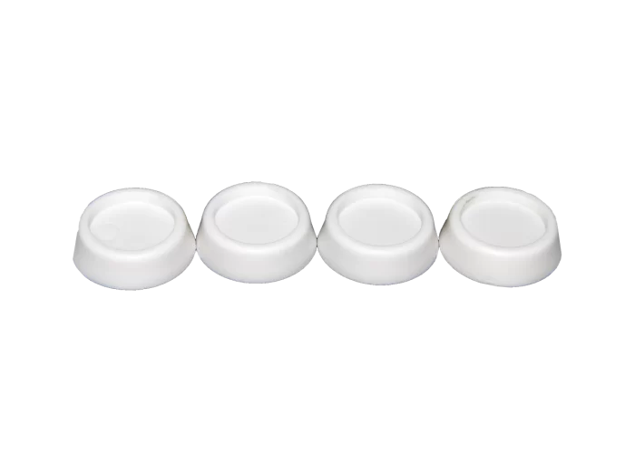 |
|
Антивибрационные подставки для стиральной машины |
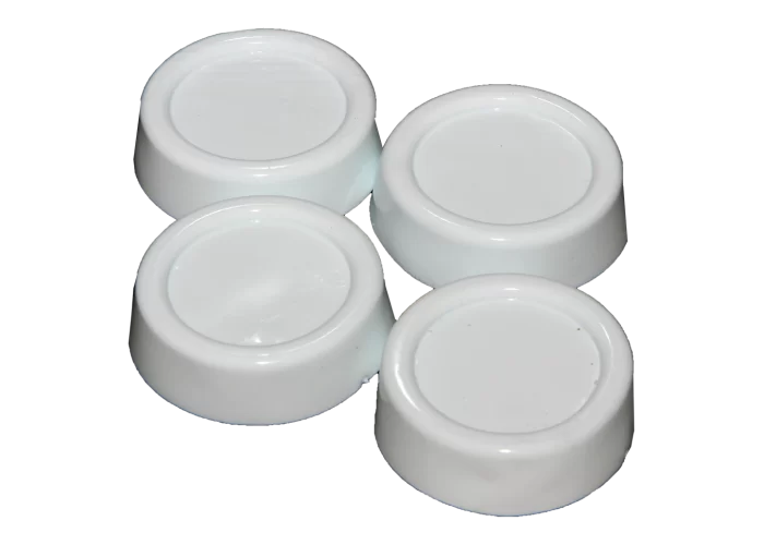 |
Манжет люка
| Модель манжета люка | фото |
|---|---|
| Манжета люка для Ardo AE, SE | 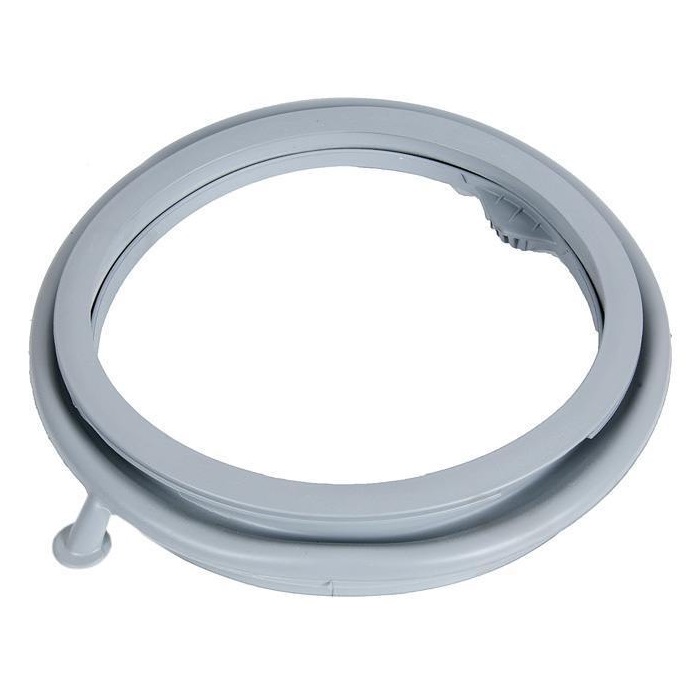 |
Ремни
| Модель ремня | фото |
|---|---|
| Ремень приводной для Ardo AE, SE | 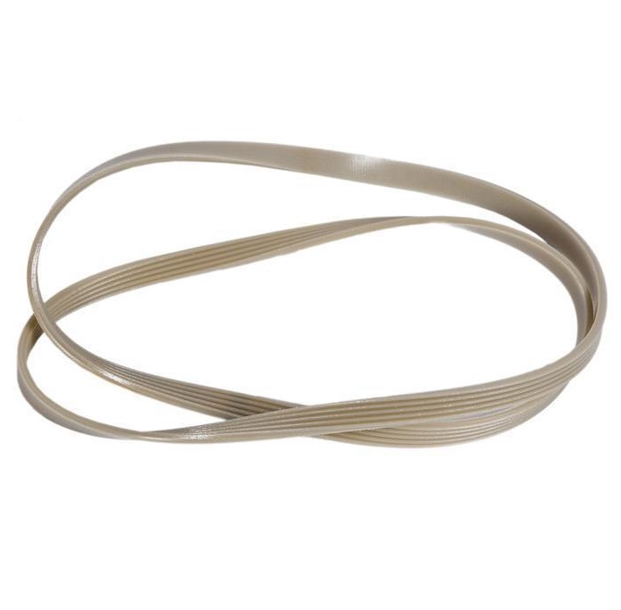 |
Подшипники
| Модель подшипника | фото |
|---|---|
| Подшипник барабана для Ardo AE, SE | 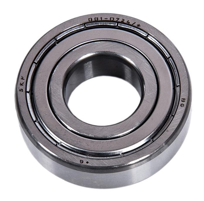 |
Сальники
| Модель сальника | фото |
|---|---|
| Сальник бака для Ardo AE, SE | 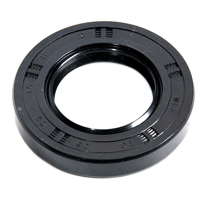 |
Ручка люка
| Модель ручки люка | фото |
|---|---|
| РУЧКА ДВЕРЦЫ ЛЮКА ДЛЯ СТИРАЛЬНОЙ МАШИНЫ АРДО (ARDO) | 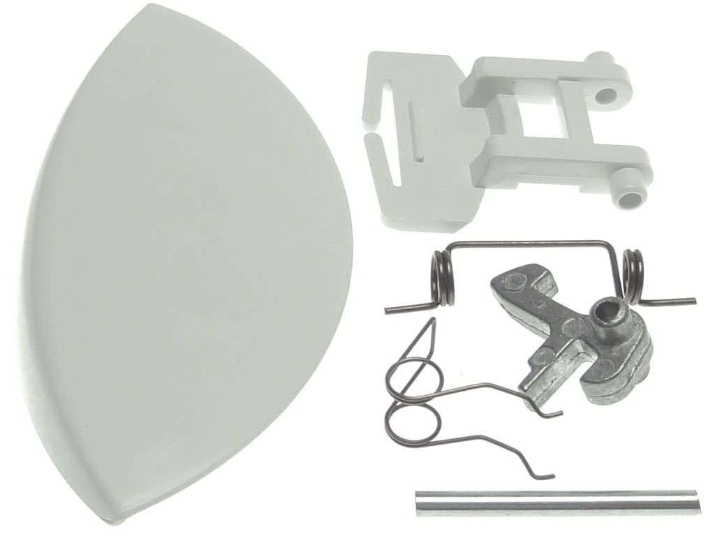 |
Электронный модуль
| Модель электронного модуля | фото |
|---|---|
| МОДУЛЬ ЭЛЕКТРОННЫЙ, ПЛАТА УПРАВЛЕНИЯ ДЛЯ СТИРАЛЬНОЙ МАШИНЫ АРДО (ARDO) AE1000X | 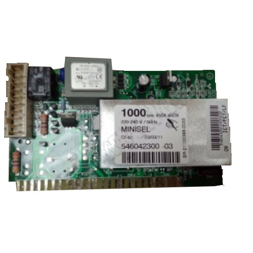 |
Блокировка люка
| Модель блокировки люка | фото |
|---|---|
| Замок люка (убл) для Ardo | 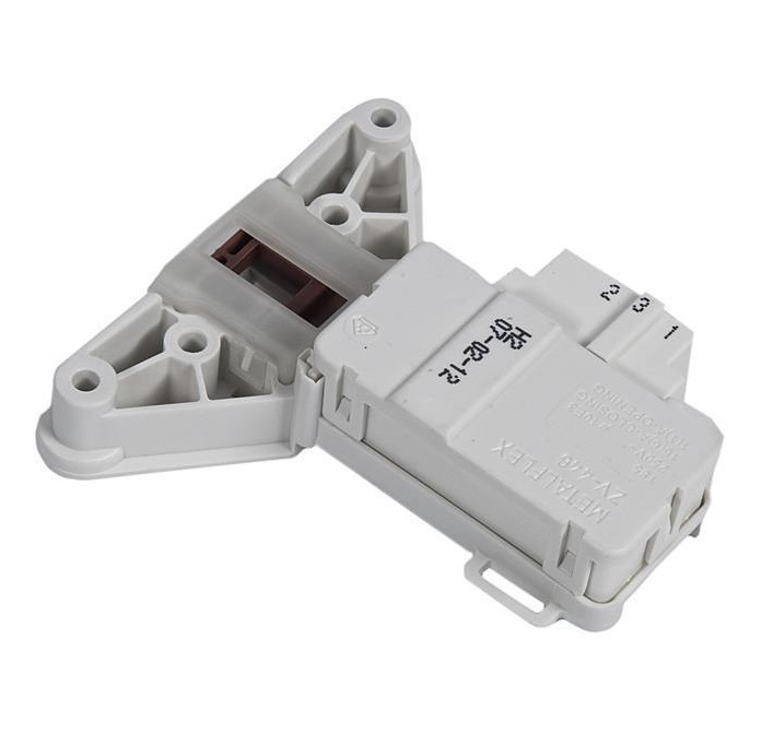 |
МОДЕЛЬ: АЕ 833, SE 800X, SE 810, SE 1000Х, SE 1010, АЕ 810, АЕ 800Х, АЕ 1033, АЕ 1010, АЕ 1000Х, АЕ 1200Х, АЕ 1400Х
ОСНОВНЫЕ ФУНКЦИИ СТИРАЛЬНОЙ МАШИНЫ
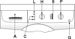
А список программ
С кнопки дополнительных функций
G кнопка вкл/выкл
Н ручка выбора скорости отжима
L кнопка пуска программы
Р ручка программатора и термостата
S контрольные лампочки выполнения фаз программы
ПОЛЬЗОВАНИЕ СТИРАЛЬНОЙ МАШИНОЙ
▼ ЦИКЛ СТИРКИ:
(последовательность операций для выполнения цикла стирки)
1. Откройте дверцу люка.
2. Загрузите белье в барабан и закройте дверцу люка.
Внимание: Запрещается перегружать стиральную машину. Не рекомендуется стирать в машине вещи, поглощающие большое количество воды, например ковры.
3. В соответствующие отделения засыпьте стиральный порошок с низким ценообразованием для автоматических стиральных машин и залейте кондиционер (см. раздел «Применение стирального порошка»).
4. Закройте контейнер для стирального порошка. Во избежание утечки воды во время работы машины не вынимайте контейнер для стирального порошка
5. Вставьте вилку в розетку и откройте кран подачи воды. Нажмите кнопку вкл/выкл G; загорится контрольная лампочка, соответствуюгщя последней установленной программе
6. При помощи ручки программатора Р установите выбранные программу и температуру, соответствующие типу ткани, из которой изготовлено предназначенное для стирки белье (см. раздел «ТАБЛИЦА ПРОГРАММ»).
7. При помощи ручки Н выберите скорость отжима (см. «УСТАНОВКА СКОРОСТИ ОТЖИМА»)
8. При помощи кнопок С установите требуемые функции (см. «ДОПОЛНИТЕЛЬНЫЕ ФУНКЦИИ») При нажатии кнопки загорятся.
9. Для пуска программы нажмите кнопку L (см. «КНОПКА ПУСКА»)
10. По завершении программы стирки нажмите кнопку вкл/выкл G, чтобы выключить стиральную машину.
11. Подождите 2 минуты, чтобы отключилось блокировочное устройство. Откройте дверцу люка и выньте белье.
12. Сухими руками выньте вилку из розетки.
13. Закройте кран подачи воды
▼ УСТАНОВКА СКОРОСТИ ОТЖИМА:
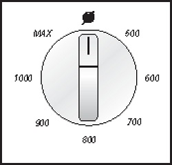
В стиральной машине предусмотрен широкий выбор скоростей отжима, которые устанавливаются в соответствии с выбранной программой перед ее пуском. Для изменения скорости отжима достаточно просто установить ручку Н в положение, соответствующее требуемому количеству оборотов. Если Вы ютите отключить отжим, ручку следует установить в положение .
ПРИМЕЧАНИЕ: Максимальная скорость отжима меняется в зависимости от модели и указана в разделе’Технические характеристики* Максимальная скорость отжима, предусмотренная для каждой программы, указана в таблице программ (если будет установлена скорость, превьшающая ото значение, стиральная машина все равно осуществит отжим на максимально допустимой для данной программы скорости)
Система защиты от дисбаланса при отжиме:
Эта стиральная машина оснащена специальной системой электронного контроля правильной балансировки загрузки Благодаря наличию этой системы перед каждым отжимом белье распределяется в барабане максимально равномерно В случае неправильного распределения белья, для обеспечения надежности скорость заключительного отжима снижается, а в случае повышенного дисбаланса заключительный отжим не производится.
ПОЛЬЗОВАНИЕ СТИРАЛЬНОЙ МАШИНОЙ
▼ КНОПКА ПУСКА:
После установки требуемой программы следует нажать эту кнопку, и машина начнет выполнение цикла стирки. При этом загорится кнопка L, указывая на начало выполнения цикла стирки.
▼ ОСТАНОВКА СТИРАЛЬНОМ МАШИНЫ:
Функция остановки предназначена для изменения программы стирки Если по какой-либо причине вовремя выполнения цикла стирки Вам понадобится изменить программу стирки, или Вы захотите добавить в машину белье, достаточно просто установить ручку программатора в положение “STOP» (остановка) (кнопка “start” начнет мигать) Затем при помощи ручки программатора установите новую программу и нажмите кнопку «START» (пуск) Перед тем как машина вновь начнет выполнять цикл стирки, вода из бака будет слита. ПРИМЕЧАНИЕ: Перед тем как снова включить машину, проверьте наличие стирального порошка в соответствующих отделениях, и при необходимости добавьте его.
ВНИМАНИЕ! Рекомендуется использовать данную функцию только в случаях крайней необходимости и не позднее, чем через 5 минут после начала выполнения программы Перед тем как открыть дверцу люка после остановки, следует подождать 2 минуты, чтобы отключилось блокировочное устройство.
ДОПОЛНИТЕЛЬНЫЕ ФУНКЦИИ
Предварительная стирка
При нажатии этой кнопки включается функция предварительной стирки при максимальной температуре 40°С.
Эта функция может использоваться только для программ стирки «ХЛОПОК» и «СИНТЕТИКА»
При выборе этой функции машина выполняет сначала ускоренную стирку при 40:С, а затем основную стирку при температуре, установленной пользователем Примечание: При использовании функции предварительной стирки порошок следует засыпать в отделения I и II контейнера для стирального порошка. Если нужно выполнить только основную стирку порошок следует засыпать в отделение II.
Дополнительное полоскание:
Стиральная машина спроектирована таким образом, чтобы расход воды был минимальным. При нажатии этой кнопки машина выполнит дополнительное полоскание. Эту функцию рекомендуется использовать в районах с очень мягкой водой, или в случае, если по окончании цикла стирки Вы замечаете в контейнере остатки стирального порошка.
Примечание: Использование дополнительных функций обусловлено установленной программой, поэтому, если данной программой не допускается использование какой-либо функции, нажать соответствующую кнопку будет невозможно (см. «ТАБЛИЦУ ПРОГРАММ»).
▼ КОНТРОЛЬ ВЫПОЛНЕНИЯ ФАЗ ПРОГРАММЫ:
На рисунке приведены 5 основных фаз цикла стирки: ПРЕДВАРИТЕЛЬНАЯ СТИРКА, ОСНОВНАЯ СТИРКА, ПОЛОСКАНИЕ, ОТЖИМ, ОКОНЧАНИЕ.
Во время выполнения цикла каждая из этих функций будет обозначаться включением соответствующей контрольной лампочки. Таким образом, можно узнать какая фаза цикла выполняется в данный момент.
По окончании отжима соответствующая контрольная лампочка будет гореть в течение примерно 2 минут, что соответствует времени, необходимому для отключения блокировочного устройства дверцы люка. Затем загорится контрольная лампочка «ОКОНЧАНИЕ»
После этого следует нажать кнопку вкл/выкл G, открыть дверцу люка и вынуть белье.
ТАБЛИЦЫ ПРОГРАММ
| Ручка программатора | Температура стирки | Символ на этикетке | Тип ткани | Отделение контейнера для стирального порошка | Скорость отжима | Кнопки дополнительных функции | |
| хлопок | 90° | Очень грязное белье из белой ткани с пятнами, в том числе органического происхсждения | |||||
| хлопок | 75° | Очень грязное постельное белье, рубашки, скатерти, полотенца из прочной ткани | Макс. (или ниже) | ||||
| хлопок* | 60° | Обычно загрязненные рубашки, скатерти, полотенца из прочной ткани | Макс. (или ниже) | ||||
| хлопок | 40° | Очень грязное белье из белой или цветной ткани с устойчивой окраской | Макс. (или ниже) | ||||
| хлопок | Макс. (или ниже) | ||||||
| 30° | Белье с нестойкой окраской, малозагрязненное белье | ||||||
| СИНТЕТИКА | 60° | Очень грязные вещи из синтетических тканей с устойчивой окраской | Макс. (или ниже) | ||||
| СИНТЕТИКА | 50° | Обычно загрязненные вещи из синтетических тканей с устойчивой окраской | 800 (или ниже) | ||||
| 800 (или ниже) | |||||||
| СИНТЕТИКА | 40° | Малозагрязненные вещи из синтетических тканей с нестойкой окраской | |||||
| СИНТЕТИКА | 30° | Малозагрязненные вещи из синтетических тканей с нестойкой окраской | 800 (или ниже) | ||||
| 800 (или ниже) | |||||||
| ДЕЛИКАТНЫЕ ТКАНИ | 40° | Вещи из тонкой хлопчатобумажной ткани, вискозы и тонких смешанных тканей | |||||
| ДЕЛИКАТНЫЕ ТКАНИ | 30° | Вещи из тонкой хлопчатобумажной ткани, вискозы и тонких смешанных тканей | 500 (или ниже) | ||||
| ДЕЛИКАТНЫЕ ТКАНИ | ХОЛОДНАЯ ВОДА | Вещи из шелка и тонких смешанных тканей | 500 (или ниже) | ||||
| 500 (или ниже) | |||||||
| ШЕРСТЬ | 40° | Вещи из шерстяных тканей, которые можно стирать в машине | |||||
| ШЕРСТЬ | 30° | Вещи из шерстяных тканей, которые можно стирать в машине | 800 (или ниже) | ||||
| ШЕРСТЬ | ХОЛОДНАЯ ВОДА | — | Вещи из шерстяных тканей, которые можно стирать в машине | 800 (или ниже) | |||
| 800 (или ниже) | |||||||
| РУЧНАЯ СТИРКА | 30° | Вещи, предназначенные для ручной стирки | |||||
| 800 (или ниже) |
дополнительная функция, действующая при включении кнопки предварительной стирки
возможность использования функции при выполнении программы
невозможность использования функции при выполнении программы
* Программа для определения класса энергопотребления в соответствии с нормой EN 60456
СИСТЕМА «EASY LOGIC»
Электронная стиральная машина оснащена системой «EASY LOGIC». Эта система автоматически определяет вес загружаемого белья и соответственно регулирует количество воды, используемой при стирке, что позволяет сократить расход воды и электроэнергии.
В случае если вес белья меньше рекомендуемой максимальной загрузки (см. «ТЕХНИЧЕСКИЕХАРАКТЕРИСТИКИ»), количество используемой для стирки воды сократится на 2 литра на каждый недостающий до максимальной загрузки килограмм белья.
В случае стирки половины или меньше половины максимальной загрузки, машина автоматически выполнит на одно полоскание меньше, чем это предусмотрено программой.
Примечание: Функция “EASY LOGIC» действует только для программ «ХЛОПОК».
ТЕХНИЧЕСКИЕ ХАРАКТЕРИСТИКИ
| МОДЕЛЬ |
АЕ 633 | SE 600Х SEB10 |
SE 1000X SE 1010 |
AE 810 АЕ 600X |
AE 1033 |
AE 1010 AE 1000X |
AE 1200X | AE 140 OX | |
| ГАБАРИТЫ: | Ширина см: | 59.5 | 59.5 | 59.5 | 59.5 | 59.5 | 59.5 | 59.5 | 59.5 |
| Высота см: | 85.0 | 85.0 | 85.0 | 85.0 | 85.0 | 85.0 | 85.0 | 85.0 | |
| Глубина см: | 33.0 | 39.5 | 39 5 | 54.5 | 33.0 | 54.5 | 54.5 | 54.5 | |
| Рекомендуемая максимальная загрузка для стирки* | 3,5 Kg | 5,0 Kg | 5,0 Kg | 5,0 Kg | 3,5 Kg | 5,0 Kg | 5,0 Kg | 5,0 Kg | |
| 1,5 Kg | 2,5 Kg | 2,5 Kg | 2,5 Kg | 1,5 Kg | 2,5 Kg | 2,5 Kg | 2,5 Kg | ||
| 1,0 Kg | 1,0 Kg | 1,0 Kg | 1,0 Kg | 1,0 Kg | 1,0 Kg | 1,0 Kg | 1,0 Kg | ||
| Отжим макс.: (об/мин) | 800 | 800 | 1000 | 800 | 1000 | 1000 | 1200 | 1400 | |
| Давление воды | мин. 0,05 МПа — макс. 1 МПа | ||||||||
| Шанс, потребляемая мощлост^Электр (месите подключение | см маркировочную табличку |
* Для того чтобы белье, загружаемое в машину было хорошо сбалансировано и во избежание повышенной вибрации во время отжима, вес предназначенного для стирки белья должен быть не менее 1 кг.
Инструкция по эксплуатации для стиральной машины Ardo AE, SE
Комплектующие для стиральной машины
ТЭН
| Модель ТЭНа | фото |
|---|---|
| Тэн для стиральной машины 0305 1950 W 200 мм изогнутый Thermowatt | |
Манжет люка
| Модель манжета люка | фото |
|---|---|
| Манжета люка для Ardo AE, SE | |
Ремни
| Модель ремня | фото |
|---|---|
| Ремень приводной для Ardo AE, SE | |
Подшипники
| Модель подшипника | фото |
|---|---|
| Подшипник барабана для Ardo AE, SE | |
Сальники
| Модель сальника | фото |
|---|---|
| Сальник бака для Ardo AE, SE | |
Ручка люка
| Модель ручки люка | фото |
|---|---|
| РУЧКА ДВЕРЦЫ ЛЮКА ДЛЯ СТИРАЛЬНОЙ МАШИНЫ АРДО (ARDO) | |
Электронный модуль
| Модель электронного модуля | фото |
|---|---|
| МОДУЛЬ ЭЛЕКТРОННЫЙ, ПЛАТА УПРАВЛЕНИЯ ДЛЯ СТИРАЛЬНОЙ МАШИНЫ АРДО (ARDO) AE1000X | |
Блокировка люка
| Модель блокировки люка | фото |
|---|---|
| Замок люка (убл) для Ardo | |
МОДЕЛЬ: АЕ 833, SE 800X, SE 810, SE 1000Х, SE 1010, АЕ 810, АЕ 800Х, АЕ 1033, АЕ 1010, АЕ 1000Х, АЕ 1200Х, АЕ 1400Х
ОСНОВНЫЕ ФУНКЦИИ СТИРАЛЬНОЙ МАШИНЫ
А список программ
С кнопки дополнительных функций
G кнопка вкл/выкл
Н ручка выбора скорости отжима
L кнопка пуска программы
Р ручка программатора и термостата
S контрольные лампочки выполнения фаз программы
ПОЛЬЗОВАНИЕ СТИРАЛЬНОЙ МАШИНОЙ
▼ ЦИКЛ СТИРКИ:
(последовательность операций для выполнения цикла стирки)
1. Откройте дверцу люка.
2. Загрузите белье в барабан и закройте дверцу люка.
Внимание: Запрещается перегружать стиральную машину. Не рекомендуется стирать в машине вещи, поглощающие большое количество воды, например ковры.
3. В соответствующие отделения засыпьте стиральный порошок с низким ценообразованием для автоматических стиральных машин и залейте кондиционер (см. раздел «Применение стирального порошка»).
4. Закройте контейнер для стирального порошка. Во избежание утечки воды во время работы машины не вынимайте контейнер для стирального порошка
5. Вставьте вилку в розетку и откройте кран подачи воды. Нажмите кнопку вкл/выкл G; загорится контрольная лампочка, соответствуюгщя последней установленной программе
6. При помощи ручки программатора Р установите выбранные программу и температуру, соответствующие типу ткани, из которой изготовлено предназначенное для стирки белье (см. раздел «ТАБЛИЦА ПРОГРАММ»).
7. При помощи ручки Н выберите скорость отжима (см. «УСТАНОВКА СКОРОСТИ ОТЖИМА»)
8. При помощи кнопок С установите требуемые функции (см. «ДОПОЛНИТЕЛЬНЫЕ ФУНКЦИИ») При нажатии кнопки загорятся.
9. Для пуска программы нажмите кнопку L (см. «КНОПКА ПУСКА»)
10. По завершении программы стирки нажмите кнопку вкл/выкл G, чтобы выключить стиральную машину.
11. Подождите 2 минуты, чтобы отключилось блокировочное устройство. Откройте дверцу люка и выньте белье.
12. Сухими руками выньте вилку из розетки.
13. Закройте кран подачи воды
▼ УСТАНОВКА СКОРОСТИ ОТЖИМА:
В стиральной машине предусмотрен широкий выбор скоростей отжима, которые устанавливаются в соответствии с выбранной программой перед ее пуском. Для изменения скорости отжима достаточно просто установить ручку Н в положение, соответствующее требуемому количеству оборотов. Если Вы ютите отключить отжим, ручку следует установить в положение .
ПРИМЕЧАНИЕ: Максимальная скорость отжима меняется в зависимости от модели и указана в разделе’Технические характеристики* Максимальная скорость отжима, предусмотренная для каждой программы, указана в таблице программ (если будет установлена скорость, превьшающая ото значение, стиральная машина все равно осуществит отжим на максимально допустимой для данной программы скорости)
Система защиты от дисбаланса при отжиме:
Эта стиральная машина оснащена специальной системой электронного контроля правильной балансировки загрузки Благодаря наличию этой системы перед каждым отжимом белье распределяется в барабане максимально равномерно В случае неправильного распределения белья, для обеспечения надежности скорость заключительного отжима снижается, а в случае повышенного дисбаланса заключительный отжим не производится.
ПОЛЬЗОВАНИЕ СТИРАЛЬНОЙ МАШИНОЙ
▼ КНОПКА ПУСКА:
После установки требуемой программы следует нажать эту кнопку, и машина начнет выполнение цикла стирки. При этом загорится кнопка L, указывая на начало выполнения цикла стирки.
▼ ОСТАНОВКА СТИРАЛЬНОМ МАШИНЫ:
Функция остановки предназначена для изменения программы стирки Если по какой-либо причине вовремя выполнения цикла стирки Вам понадобится изменить программу стирки, или Вы захотите добавить в машину белье, достаточно просто установить ручку программатора в положение “STOP» (остановка) (кнопка “start” начнет мигать) Затем при помощи ручки программатора установите новую программу и нажмите кнопку «START» (пуск) Перед тем как машина вновь начнет выполнять цикл стирки, вода из бака будет слита. ПРИМЕЧАНИЕ: Перед тем как снова включить машину, проверьте наличие стирального порошка в соответствующих отделениях, и при необходимости добавьте его.
ВНИМАНИЕ! Рекомендуется использовать данную функцию только в случаях крайней необходимости и не позднее, чем через 5 минут после начала выполнения программы Перед тем как открыть дверцу люка после остановки, следует подождать 2 минуты, чтобы отключилось блокировочное устройство.
ДОПОЛНИТЕЛЬНЫЕ ФУНКЦИИ
Предварительная стирка
При нажатии этой кнопки включается функция предварительной стирки при максимальной температуре 40°С.
Эта функция может использоваться только для программ стирки «ХЛОПОК» и «СИНТЕТИКА»
При выборе этой функции машина выполняет сначала ускоренную стирку при 40:С, а затем основную стирку при температуре, установленной пользователем Примечание: При использовании функции предварительной стирки порошок следует засыпать в отделения I и II контейнера для стирального порошка. Если нужно выполнить только основную стирку порошок следует засыпать в отделение II.
Дополнительное полоскание:
Стиральная машина спроектирована таким образом, чтобы расход воды был минимальным. При нажатии этой кнопки машина выполнит дополнительное полоскание. Эту функцию рекомендуется использовать в районах с очень мягкой водой, или в случае, если по окончании цикла стирки Вы замечаете в контейнере остатки стирального порошка.
Примечание: Использование дополнительных функций обусловлено установленной программой, поэтому, если данной программой не допускается использование какой-либо функции, нажать соответствующую кнопку будет невозможно (см. «ТАБЛИЦУ ПРОГРАММ»).
▼ КОНТРОЛЬ ВЫПОЛНЕНИЯ ФАЗ ПРОГРАММЫ:
На рисунке приведены 5 основных фаз цикла стирки: ПРЕДВАРИТЕЛЬНАЯ СТИРКА, ОСНОВНАЯ СТИРКА, ПОЛОСКАНИЕ, ОТЖИМ, ОКОНЧАНИЕ.
Во время выполнения цикла каждая из этих функций будет обозначаться включением соответствующей контрольной лампочки. Таким образом, можно узнать какая фаза цикла выполняется в данный момент.
По окончании отжима соответствующая контрольная лампочка будет гореть в течение примерно 2 минут, что соответствует времени, необходимому для отключения блокировочного устройства дверцы люка. Затем загорится контрольная лампочка «ОКОНЧАНИЕ»
После этого следует нажать кнопку вкл/выкл G, открыть дверцу люка и вынуть белье.
ТАБЛИЦЫ ПРОГРАММ
| Ручка программатора | Температура стирки | Символ на этикетке | Тип ткани | Отделение контейнера для стирального порошка | Скорость отжима | Кнопки дополнительных функции | |
| хлопок | 90° | Очень грязное белье из белой ткани с пятнами, в том числе органического происхсждения | |||||
| хлопок | 75° | Очень грязное постельное белье, рубашки, скатерти, полотенца из прочной ткани | Макс. (или ниже) | ||||
| хлопок* | 60° | Обычно загрязненные рубашки, скатерти, полотенца из прочной ткани | Макс. (или ниже) | ||||
| хлопок | 40° | Очень грязное белье из белой или цветной ткани с устойчивой окраской | Макс. (или ниже) | ||||
| хлопок | Макс. (или ниже) | ||||||
| 30° | Белье с нестойкой окраской, малозагрязненное белье | ||||||
| СИНТЕТИКА | 60° | Очень грязные вещи из синтетических тканей с устойчивой окраской | Макс. (или ниже) | ||||
| СИНТЕТИКА | 50° | Обычно загрязненные вещи из синтетических тканей с устойчивой окраской | 800 (или ниже) | ||||
| 800 (или ниже) | |||||||
| СИНТЕТИКА | 40° | Малозагрязненные вещи из синтетических тканей с нестойкой окраской | |||||
| СИНТЕТИКА | 30° | Малозагрязненные вещи из синтетических тканей с нестойкой окраской | 800 (или ниже) | ||||
| 800 (или ниже) | |||||||
| ДЕЛИКАТНЫЕ ТКАНИ | 40° | Вещи из тонкой хлопчатобумажной ткани, вискозы и тонких смешанных тканей | |||||
| ДЕЛИКАТНЫЕ ТКАНИ | 30° | Вещи из тонкой хлопчатобумажной ткани, вискозы и тонких смешанных тканей | 500 (или ниже) | ||||
| ДЕЛИКАТНЫЕ ТКАНИ | ХОЛОДНАЯ ВОДА | Вещи из шелка и тонких смешанных тканей | 500 (или ниже) | ||||
| 500 (или ниже) | |||||||
| ШЕРСТЬ | 40° | Вещи из шерстяных тканей, которые можно стирать в машине | |||||
| ШЕРСТЬ | 30° | Вещи из шерстяных тканей, которые можно стирать в машине | 800 (или ниже) | ||||
| ШЕРСТЬ | ХОЛОДНАЯ ВОДА | — | Вещи из шерстяных тканей, которые можно стирать в машине | 800 (или ниже) | |||
| 800 (или ниже) | |||||||
| РУЧНАЯ СТИРКА | 30° | Вещи, предназначенные для ручной стирки | |||||
| 800 (или ниже) |
дополнительная функция, действующая при включении кнопки предварительной стирки
возможность использования функции при выполнении программы
невозможность использования функции при выполнении программы
* Программа для определения класса энергопотребления в соответствии с нормой EN 60456
СИСТЕМА «EASY LOGIC»
Электронная стиральная машина оснащена системой «EASY LOGIC». Эта система автоматически определяет вес загружаемого белья и соответственно регулирует количество воды, используемой при стирке, что позволяет сократить расход воды и электроэнергии.
В случае если вес белья меньше рекомендуемой максимальной загрузки (см. «ТЕХНИЧЕСКИЕХАРАКТЕРИСТИКИ»), количество используемой для стирки воды сократится на 2 литра на каждый недостающий до максимальной загрузки килограмм белья.
В случае стирки половины или меньше половины максимальной загрузки, машина автоматически выполнит на одно полоскание меньше, чем это предусмотрено программой.
Примечание: Функция “EASY LOGIC» действует только для программ «ХЛОПОК».
ТЕХНИЧЕСКИЕ ХАРАКТЕРИСТИКИ
| МОДЕЛЬ | АЕ 633 | SE 600Х SEB10 |
SE 1000X SE 1010 |
AE 810 АЕ 600X |
AE 1033 |
AE 1010 AE 1000X |
AE 1200X | AE 140 OX | |
| ГАБАРИТЫ: | Ширина см: | 59.5 | 59.5 | 59.5 | 59.5 | 59.5 | 59.5 | 59.5 | 59.5 |
| Высота см: | 85.0 | 85.0 | 85.0 | 85.0 | 85.0 | 85.0 | 85.0 | 85.0 | |
| Глубина см: | 33.0 | 39.5 | 39 5 | 54.5 | 33.0 | 54.5 | 54.5 | 54.5 | |
| Рекомендуемая максимальная загрузка для стирки* | 3,5 Kg | 5,0 Kg | 5,0 Kg | 5,0 Kg | 3,5 Kg | 5,0 Kg | 5,0 Kg | 5,0 Kg | |
| 1,5 Kg | 2,5 Kg | 2,5 Kg | 2,5 Kg | 1,5 Kg | 2,5 Kg | 2,5 Kg | 2,5 Kg | ||
| 1,0 Kg | 1,0 Kg | 1,0 Kg | 1,0 Kg | 1,0 Kg | 1,0 Kg | 1,0 Kg | 1,0 Kg | ||
| Отжим макс.: (об/мин) | 800 | 800 | 1000 | 800 | 1000 | 1000 | 1200 | 1400 | |
| Давление воды | мин. 0,05 МПа — макс. 1 МПа | ||||||||
| Шанс, потребляемая мощлост^Электр (месите подключение | см маркировочную табличку |
* Для того чтобы белье, загружаемое в машину было хорошо сбалансировано и во избежание повышенной вибрации во время отжима, вес предназначенного для стирки белья должен быть не менее 1 кг.
Инструкция по эксплуатации для стиральной машины Ardo AE, SE
Комплектующие для стиральной машины
ТЭН
| Модель ТЭНа | фото |
|---|---|
| Тэн для стиральной машины 0305 1950 W 200 мм изогнутый Thermowatt | |
Манжет люка
| Модель манжета люка | фото |
|---|---|
| Манжета люка для Ardo AE, SE | |
Ремни
| Модель ремня | фото |
|---|---|
| Ремень приводной для Ardo AE, SE | |
Подшипники
| Модель подшипника | фото |
|---|---|
| Подшипник барабана для Ardo AE, SE | |
Сальники
| Модель сальника | фото |
|---|---|
| Сальник бака для Ardo AE, SE | |
Ручка люка
| Модель ручки люка | фото |
|---|---|
| РУЧКА ДВЕРЦЫ ЛЮКА ДЛЯ СТИРАЛЬНОЙ МАШИНЫ АРДО (ARDO) | |
Электронный модуль
| Модель электронного модуля | фото |
|---|---|
| МОДУЛЬ ЭЛЕКТРОННЫЙ, ПЛАТА УПРАВЛЕНИЯ ДЛЯ СТИРАЛЬНОЙ МАШИНЫ АРДО (ARDO) AE1000X | |
Блокировка люка
| Модель блокировки люка | фото |
|---|---|
| Замок люка (убл) для Ardo | |
МОДЕЛЬ: АЕ 833, SE 800X, SE 810, SE 1000Х, SE 1010, АЕ 810, АЕ 800Х, АЕ 1033, АЕ 1010, АЕ 1000Х, АЕ 1200Х, АЕ 1400Х
ОСНОВНЫЕ ФУНКЦИИ СТИРАЛЬНОЙ МАШИНЫ
А список программ
С кнопки дополнительных функций
G кнопка вкл/выкл
Н ручка выбора скорости отжима
L кнопка пуска программы
Р ручка программатора и термостата
S контрольные лампочки выполнения фаз программы
ПОЛЬЗОВАНИЕ СТИРАЛЬНОЙ МАШИНОЙ
▼ ЦИКЛ СТИРКИ:
(последовательность операций для выполнения цикла стирки)
1. Откройте дверцу люка.
2. Загрузите белье в барабан и закройте дверцу люка.
Внимание: Запрещается перегружать стиральную машину. Не рекомендуется стирать в машине вещи, поглощающие большое количество воды, например ковры.
3. В соответствующие отделения засыпьте стиральный порошок с низким ценообразованием для автоматических стиральных машин и залейте кондиционер (см. раздел «Применение стирального порошка»).
4. Закройте контейнер для стирального порошка. Во избежание утечки воды во время работы машины не вынимайте контейнер для стирального порошка
5. Вставьте вилку в розетку и откройте кран подачи воды. Нажмите кнопку вкл/выкл G; загорится контрольная лампочка, соответствуюгщя последней установленной программе
6. При помощи ручки программатора Р установите выбранные программу и температуру, соответствующие типу ткани, из которой изготовлено предназначенное для стирки белье (см. раздел «ТАБЛИЦА ПРОГРАММ»).
7. При помощи ручки Н выберите скорость отжима (см. «УСТАНОВКА СКОРОСТИ ОТЖИМА»)
8. При помощи кнопок С установите требуемые функции (см. «ДОПОЛНИТЕЛЬНЫЕ ФУНКЦИИ») При нажатии кнопки загорятся.
9. Для пуска программы нажмите кнопку L (см. «КНОПКА ПУСКА»)
10. По завершении программы стирки нажмите кнопку вкл/выкл G, чтобы выключить стиральную машину.
11. Подождите 2 минуты, чтобы отключилось блокировочное устройство. Откройте дверцу люка и выньте белье.
12. Сухими руками выньте вилку из розетки.
13. Закройте кран подачи воды
▼ УСТАНОВКА СКОРОСТИ ОТЖИМА:
В стиральной машине предусмотрен широкий выбор скоростей отжима, которые устанавливаются в соответствии с выбранной программой перед ее пуском. Для изменения скорости отжима достаточно просто установить ручку Н в положение, соответствующее требуемому количеству оборотов. Если Вы ютите отключить отжим, ручку следует установить в положение .
ПРИМЕЧАНИЕ: Максимальная скорость отжима меняется в зависимости от модели и указана в разделе’Технические характеристики* Максимальная скорость отжима, предусмотренная для каждой программы, указана в таблице программ (если будет установлена скорость, превьшающая ото значение, стиральная машина все равно осуществит отжим на максимально допустимой для данной программы скорости)
Система защиты от дисбаланса при отжиме:
Эта стиральная машина оснащена специальной системой электронного контроля правильной балансировки загрузки Благодаря наличию этой системы перед каждым отжимом белье распределяется в барабане максимально равномерно В случае неправильного распределения белья, для обеспечения надежности скорость заключительного отжима снижается, а в случае повышенного дисбаланса заключительный отжим не производится.
ПОЛЬЗОВАНИЕ СТИРАЛЬНОЙ МАШИНОЙ
▼ КНОПКА ПУСКА:
После установки требуемой программы следует нажать эту кнопку, и машина начнет выполнение цикла стирки. При этом загорится кнопка L, указывая на начало выполнения цикла стирки.
▼ ОСТАНОВКА СТИРАЛЬНОМ МАШИНЫ:
Функция остановки предназначена для изменения программы стирки Если по какой-либо причине вовремя выполнения цикла стирки Вам понадобится изменить программу стирки, или Вы захотите добавить в машину белье, достаточно просто установить ручку программатора в положение “STOP» (остановка) (кнопка “start” начнет мигать) Затем при помощи ручки программатора установите новую программу и нажмите кнопку «START» (пуск) Перед тем как машина вновь начнет выполнять цикл стирки, вода из бака будет слита. ПРИМЕЧАНИЕ: Перед тем как снова включить машину, проверьте наличие стирального порошка в соответствующих отделениях, и при необходимости добавьте его.
ВНИМАНИЕ! Рекомендуется использовать данную функцию только в случаях крайней необходимости и не позднее, чем через 5 минут после начала выполнения программы Перед тем как открыть дверцу люка после остановки, следует подождать 2 минуты, чтобы отключилось блокировочное устройство.
ДОПОЛНИТЕЛЬНЫЕ ФУНКЦИИ
Предварительная стирка
При нажатии этой кнопки включается функция предварительной стирки при максимальной температуре 40°С.
Эта функция может использоваться только для программ стирки «ХЛОПОК» и «СИНТЕТИКА»
При выборе этой функции машина выполняет сначала ускоренную стирку при 40:С, а затем основную стирку при температуре, установленной пользователем Примечание: При использовании функции предварительной стирки порошок следует засыпать в отделения I и II контейнера для стирального порошка. Если нужно выполнить только основную стирку порошок следует засыпать в отделение II.
Дополнительное полоскание:
Стиральная машина спроектирована таким образом, чтобы расход воды был минимальным. При нажатии этой кнопки машина выполнит дополнительное полоскание. Эту функцию рекомендуется использовать в районах с очень мягкой водой, или в случае, если по окончании цикла стирки Вы замечаете в контейнере остатки стирального порошка.
Примечание: Использование дополнительных функций обусловлено установленной программой, поэтому, если данной программой не допускается использование какой-либо функции, нажать соответствующую кнопку будет невозможно (см. «ТАБЛИЦУ ПРОГРАММ»).
▼ КОНТРОЛЬ ВЫПОЛНЕНИЯ ФАЗ ПРОГРАММЫ:
На рисунке приведены 5 основных фаз цикла стирки: ПРЕДВАРИТЕЛЬНАЯ СТИРКА, ОСНОВНАЯ СТИРКА, ПОЛОСКАНИЕ, ОТЖИМ, ОКОНЧАНИЕ.
Во время выполнения цикла каждая из этих функций будет обозначаться включением соответствующей контрольной лампочки. Таким образом, можно узнать какая фаза цикла выполняется в данный момент.
По окончании отжима соответствующая контрольная лампочка будет гореть в течение примерно 2 минут, что соответствует времени, необходимому для отключения блокировочного устройства дверцы люка. Затем загорится контрольная лампочка «ОКОНЧАНИЕ»
После этого следует нажать кнопку вкл/выкл G, открыть дверцу люка и вынуть белье.
ТАБЛИЦЫ ПРОГРАММ
| Ручка программатора | Температура стирки | Символ на этикетке | Тип ткани | Отделение контейнера для стирального порошка | Скорость отжима | Кнопки дополнительных функции | |
| хлопок | 90° | Очень грязное белье из белой ткани с пятнами, в том числе органического происхсждения | |||||
| хлопок | 75° | Очень грязное постельное белье, рубашки, скатерти, полотенца из прочной ткани | Макс. (или ниже) | ||||
| хлопок* | 60° | Обычно загрязненные рубашки, скатерти, полотенца из прочной ткани | Макс. (или ниже) | ||||
| хлопок | 40° | Очень грязное белье из белой или цветной ткани с устойчивой окраской | Макс. (или ниже) | ||||
| хлопок | Макс. (или ниже) | ||||||
| 30° | Белье с нестойкой окраской, малозагрязненное белье | ||||||
| СИНТЕТИКА | 60° | Очень грязные вещи из синтетических тканей с устойчивой окраской | Макс. (или ниже) | ||||
| СИНТЕТИКА | 50° | Обычно загрязненные вещи из синтетических тканей с устойчивой окраской | 800 (или ниже) | ||||
| 800 (или ниже) | |||||||
| СИНТЕТИКА | 40° | Малозагрязненные вещи из синтетических тканей с нестойкой окраской | |||||
| СИНТЕТИКА | 30° | Малозагрязненные вещи из синтетических тканей с нестойкой окраской | 800 (или ниже) | ||||
| 800 (или ниже) | |||||||
| ДЕЛИКАТНЫЕ ТКАНИ | 40° | Вещи из тонкой хлопчатобумажной ткани, вискозы и тонких смешанных тканей | |||||
| ДЕЛИКАТНЫЕ ТКАНИ | 30° | Вещи из тонкой хлопчатобумажной ткани, вискозы и тонких смешанных тканей | 500 (или ниже) | ||||
| ДЕЛИКАТНЫЕ ТКАНИ | ХОЛОДНАЯ ВОДА | Вещи из шелка и тонких смешанных тканей | 500 (или ниже) | ||||
| 500 (или ниже) | |||||||
| ШЕРСТЬ | 40° | Вещи из шерстяных тканей, которые можно стирать в машине | |||||
| ШЕРСТЬ | 30° | Вещи из шерстяных тканей, которые можно стирать в машине | 800 (или ниже) | ||||
| ШЕРСТЬ | ХОЛОДНАЯ ВОДА | — | Вещи из шерстяных тканей, которые можно стирать в машине | 800 (или ниже) | |||
| 800 (или ниже) | |||||||
| РУЧНАЯ СТИРКА | 30° | Вещи, предназначенные для ручной стирки | |||||
| 800 (или ниже) |
дополнительная функция, действующая при включении кнопки предварительной стирки
возможность использования функции при выполнении программы
невозможность использования функции при выполнении программы
* Программа для определения класса энергопотребления в соответствии с нормой EN 60456
СИСТЕМА «EASY LOGIC»
Электронная стиральная машина оснащена системой «EASY LOGIC». Эта система автоматически определяет вес загружаемого белья и соответственно регулирует количество воды, используемой при стирке, что позволяет сократить расход воды и электроэнергии.
В случае если вес белья меньше рекомендуемой максимальной загрузки (см. «ТЕХНИЧЕСКИЕХАРАКТЕРИСТИКИ»), количество используемой для стирки воды сократится на 2 литра на каждый недостающий до максимальной загрузки килограмм белья.
В случае стирки половины или меньше половины максимальной загрузки, машина автоматически выполнит на одно полоскание меньше, чем это предусмотрено программой.
Примечание: Функция “EASY LOGIC» действует только для программ «ХЛОПОК».
ТЕХНИЧЕСКИЕ ХАРАКТЕРИСТИКИ
| МОДЕЛЬ | АЕ 633 | SE 600Х SEB10 |
SE 1000X SE 1010 |
AE 810 АЕ 600X |
AE 1033 |
AE 1010 AE 1000X |
AE 1200X | AE 140 OX | |
| ГАБАРИТЫ: | Ширина см: | 59.5 | 59.5 | 59.5 | 59.5 | 59.5 | 59.5 | 59.5 | 59.5 |
| Высота см: | 85.0 | 85.0 | 85.0 | 85.0 | 85.0 | 85.0 | 85.0 | 85.0 | |
| Глубина см: | 33.0 | 39.5 | 39 5 | 54.5 | 33.0 | 54.5 | 54.5 | 54.5 | |
| Рекомендуемая максимальная загрузка для стирки* | 3,5 Kg | 5,0 Kg | 5,0 Kg | 5,0 Kg | 3,5 Kg | 5,0 Kg | 5,0 Kg | 5,0 Kg | |
| 1,5 Kg | 2,5 Kg | 2,5 Kg | 2,5 Kg | 1,5 Kg | 2,5 Kg | 2,5 Kg | 2,5 Kg | ||
| 1,0 Kg | 1,0 Kg | 1,0 Kg | 1,0 Kg | 1,0 Kg | 1,0 Kg | 1,0 Kg | 1,0 Kg | ||
| Отжим макс.: (об/мин) | 800 | 800 | 1000 | 800 | 1000 | 1000 | 1200 | 1400 | |
| Давление воды | мин. 0,05 МПа — макс. 1 МПа | ||||||||
| Шанс, потребляемая мощлост^Электр (месите подключение | см маркировочную табличку |
* Для того чтобы белье, загружаемое в машину было хорошо сбалансировано и во избежание повышенной вибрации во время отжима, вес предназначенного для стирки белья должен быть не менее 1 кг.
1 EasyLogic PM2100 series User Manual NHA /2016
2 Legal Information The Schneider Electric brand and any registered trademarks of Schneider Electric Industries SAS referred to in this guide are the sole property of Schneider Electric SA and its subsidiaries. They may not be used for any purpose without the owner’s permission, given in writing. This guide and its content are protected, within the meaning of the French intellectual property code (Code de la propriété intellectuelle français, referred to hereafter as «the Code»), under the laws of copyright covering texts, drawings and models, as well as by trademark law. You agree not to reproduce, other than for your own personal, noncommercial use as defined in the Code, all or part of this guide on any medium whatsoever without Schneider Electric’s permission, given in writing. You also agree not to establish any hypertext links to this guide or its content. Schneider Electric does not grant any right or license for the personal and noncommercial use of the guide or its content, except for a non-exclusive license to consult it on an «as is» basis, at your own risk. All other rights are reserved. Electrical equipment should be installed, operated, serviced, and maintained only by qualified personnel. No responsibility is assumed by Schneider Electric for any consequences arising out of the use of this material. As standards, specifications, and designs change from time to time, please ask for confirmation of the information given in this publication.
3 Safety information Important information Read these instructions carefully and look at the equipment to become familiar with the device before trying to install, operate, service or maintain it. The following special messages may appear throughout this bulletin or on the equipment to warn of potential hazards or to call attention to information that clarifies or simplifies a procedure. The addition of either symbol to a Danger or Warning safety label indicates that an electrical hazard exists which will result in personal injury if the instructions are not followed. This is the safety alert symbol. It is used to alert you to potential personal injury hazards. Obey all safety messages that follow this symbol to avoid possible injury or death. Please note Electrical equipment should be installed, operated, serviced and maintained only by qualified personnel. No responsibility is assumed by Schneider Electric for any consequences arising out of the use of this material. A qualified person is one who has skills and knowledge related to the construction, installation, and operation of electrical equipment and has received safety training to recognize and avoid the hazards involved. NHA
4 Notices FCC This equipment has been tested and found to comply with the limits for a Class A digital device, pursuant to Part 15 of the FCC rules. These limits are designed to provide reasonable protection against harmful interference when the equipment is operated in a commercial environment. This equipment generates, uses, and can radiate radio frequency energy and, if not installed and used in accordance with the instruction manual, may cause harmful interference to radio communications. Operation of this equipment in a residential area is likely to cause harmful interference in which case the user will be required to correct the interference at his own expense. The user is cautioned that any changes or modifications not expressly approved by Schneider Electric could void the user s authority to operate the equipment. This digital apparatus complies with CAN ICES-3 (A) /NMB-3(A). 4 NHA
5 Table of Contents FCC…4 Safety precautions…9 Introduction…10 Meter Overview…10 Meter Features…10 Feature summary Mounting adaptors Measured parameters…12 Meter configuration…13 Firmware consideration…14 Hardware references…15 PM2100 meter models and accessories…15 Meter models…15 Meter accessories…15 Supplemental information…15 Panel Meter…15 LED Indicators…16 Meter mounting…16 Meter wiring…17 Direct connect voltage limits…17 Balanced system considerations…18 Balanced 3-phase Wye system with 2 CTs…19 Balanced 3-phase Wye or Delta system with 1CT…19 Serial communications…19 RS-485 wiring…19 Pulse output…19 I/O Modules…20 Configuring optional I/O module using ION Setup…21 Display and meter setup…23 Display overview…23 LED Indicators…23 Button functions…24 Meter screen menus…25 Remote meter setup…39 Overview…39 ION Setup…39 RS-485 port setup…39 Meter setup through RS Meter configuration using ION Setup…39 Viewing meter data…40 Viewing meter data from the display…40 Meters data screens…40 Meter data display screens…40 Using ION Setup to view or modify configuration data…41 Using software to view meter data…41 Power Monitoring Expert…42 NHA
6 PowerScada Expert…42 Modbus command interface…42 Alarms…43 Alarms overview…43 Alarm types…43 Unary alarms…43 Available unary alarms…43 Digital alarms…43 Digital alarm with setpoint delay…43 Available digital alarms…44 Standard alarms…44 Maximum allowable setpoint…45 Available standard alarms…46 Alarm priorities…47 Alarm setup overview…48 Built-in error-checking…48 LED alarm indicator…50 Configuring the LED for alarms using ION Setup…50 Alarms counters…50 Alarms rollover value…50 Meter logging…51 Logs overview…51 Setting up the data log…51 Saving the data log contents using ION Setup…51 Alarm log…52 Meter resets…53 Meter resets…53 Meter Initialization…53 Performing resets using ION Setup…53 Measurements and calculations…54 Meter Initialization…54 Real-time readings…54 Energy measurements…54 Min/max values…54 Power demand…54 Current demand…57 Timer…58 Active load timer…58 Meter operation timer…58 Run Time…58 Power quality…59 Harmonics overview…59 Total harmonic distortion…59 Displaying harmonics data…59 Maintenance and upgrades…61 Maintenance overview…61 Troubleshooting LED indicators…61 Meter memory…61 Meter battery…61 Viewing firmware version, model and serial number NHA
7 Firmware upgrades…62 Technical assistance…62 Verifying accuracy…63 Overview of meter accuracy…63 Accuracy test requirements…63 Signal and power source…63 Control equipment…63 Environment…63 Reference device or energy standard…64 Verifying accuracy test…64 Required pulses calculation for accuracy verification testing…65 Total power calculation for accuracy verification testing…66 Percentage error calculation for accuracy verification testing…66 Accuracy verification test points…66 Energy pulsing considerations…67 VT and CT considerations…67 Example calculations…68 Adjustments to allow energy pulsing at the pulse outputs…68 Typical sources of test errors…69 Power and power factor…70 Power and power factor…70 Current phase shift from voltage…70 Real, reactive and apparent power (PQS)…70 Power flow…71 Power factor (PF)…71 True PF and displacement PF…71 Meter specifications…74 Specifications…74 Mechanical characteristics…74 Electrical characteristics…74 Environmental characteristics…76 EMC (electromagnetic compatibility)*…76 Safety…76 RS-485 communications…77 Pulse output…77 Real-time clock…77 NHA
8
9 Safety precautions Safety precautions Installation, wiring, testing and service must be performed in accordance with all local and national electrical codes. DANGER HAZARD OF ELECTRIC SHOCK, EXPLOSION, OR ARC FLASH Apply appropriate personal protective equipment (PPE) and follow safe electrical work practices. See NFPA 70E in the USA, CSA Z462 or applicable local standards. Turn off all power supplying this device and the equipment in which it is installed before working on the device or equipment. Always use a properly rated voltage sensing device to confirm that all power is off. Do not exceed the device s ratings for maximum limits. Never short the secondary of a potential/voltage transformer (PT/VT). Never open circuit a current transformer (CT). Always use grounded external CTs for current inputs. Replace all devices, doors and covers before turning on power to this equipment. Failure to follow these instructions will result in death or serious injury. UNINTENDED OPERATION WARNING Do not use this device for critical control or protection applications where human or equipment safety relies on the operation of the control circuit. Failure to follow these instructions can result in death, serious injury, or equipment damage. NHA
10 Introduction Introduction Meter Overview The PM2100 series meters are digital meters that offer comprehensive 3-phase electrical instrumentation and load management facilities in a compact and rugged package. The meters offer value for the demanding needs of your energy monitoring and cost management applications. All meters in the PM2100 series range comply with Class 1, or Class 0.5S accuracy standards and feature high quality, reliability and affordability in a compact and easy to install format. Meter Features The PM2100 series meter supports many features, a few of the features are listed below: LED display screen: Intuitive self-guided navigation using three buttons LED display, with three lines of concurrent values. Two columns of LEDs given on the either side of the meter s front panel indicate the parameter name being displayed. Energy accounting and balancing Measurement of both True PF and Displacement PF Active, reactive, and apparent energy readings Min/Max values of instantaneous parameters with timestamp. Cyber security: The meter enables disabling the RS-485 port through front panel keys against unauthorized access. This feature can also be used for toggling between the RTU devices in case of limited availability of nodes in software system. 12 AM snap shot: The meter features include a 12 AM snap shot of average voltage, average current, total active power, and delivered energy. You can use the meter as a stand-alone device, but its extensive capabilities are fully realized when used as part of an energy management system. For applications, feature details and the most current and complete specifications of the PM2100 meters, see the EasyLogic PM2000 series technical datasheet at Feature summary Parameter PM2110 PM2120 PM2130 Accuracy Class for Wh Class 1 Class 1 Class 0.5S Accuracy Class for VARh Sampling rate per cycle Current: Per-phase and 3 phase average Calculated neutral current Voltage: V L-N — per-phase and 3 phase average V L-L — per-phase and 3 phase average Power Factor Per phase and 3 phase total True PF True PF Displacement PF * True PF Displacement PF * Frequency 10 NHA
11 Introduction Parameter PM2110 PM2120 PM2130 Power: Active power (kw) — Phase wise and total Apparent power (kva) — Phase wise and total Reactive power (kvar) — Phase wise and total 3 Phase unbalance Current Current Voltage * Current Voltage * Demand parameters (kw, kva, kvar, I) Last demand Present demand Predictive demand (no timestamp) Peak demand: Timestamp for peak demand * Energy: kwh, kvah, kvarh (4 Quadrant) Delivered (Import / Forward) Received (Export / Reverse) Delivered Received Delivered Received Total * Delivered Received Total * Net * Net * Last cleared (Old) * Last cleared (Old) * Meter On hours * Load Run hours * Power Interruptions * THD: Voltage L-N Voltage L-L Current per phase Individual Harmonics * Up to 15th individual harmonics Up to 31st individual harmonics Min / Max with timestamp * V L-L average V L-N average Current average Frequency Active power, Total Apparent power, Total Reactive power, Total Power factor, Total RTC Communication POP RS-485 Modbus RTU RS-485 Modbus RTU Expandable Analog IO modules (1 input & 1 output) Expandable Analog IO modules (2 inputs & 2 outputs) Expandable Digital IO modules (2 inputs & 2 outputs) Data Logging Energy (W, VA, VAR): Delivered / Received Power: Active / Apparent / Reactive Demand (W, VA, VAR, A): Last / Present / Predictive * Indicates features that can be read through communication only Mounting adaptors There are different mounting adaptor accessories that can help when installing your meter in existing panels and cutouts where the default mounting hardware is not appropriate. Mounting adaptor kits are ordered separately from the meter. NHA
12 Introduction Measured parameters Energy The meter provides bi-directional, 4-quadrant, Class 1 / Class 0.5S accurate energy metering. The meter stores all accumulated active, reactive, and apparent energy parameters in nonvolatile memory: kwh, kvarh, kvah delivered kwh, kvarh, kvah received kwh, kvarh, kvah delivered + received kwh, kvarh, kvah delivered received Demand The meter provides last, present, predicted, and maximum (peak) demand values, and a timestamp when the maximum (peak) demand occurred. The meter supports standard demand calculation methods, including sliding block, fixed block, rolling block, thermal and synchronized. Peak demand registers can be reset manually (password protected). Demand measurements include: W, VAR, VA demand total Amps demand average Instantaneous The meter provides highly accurate 1-second measurements, average values, including true RMS, per phase and total for: Per phase and average voltage (line-to-line, line-to-neutral) Per phase and average current, and neutral current Per phase and total power (VA, W, Var) True and displacement power factor System frequency Power quality The meter provides complete harmonic distortion metering, recording, and realtime reporting, up to the 15 th harmonic for PM2120 and up to 31 st harmonic for PM2130 for all voltage and current inputs. The following power quality measurements are available: PM2120: Individual odd harmonics up to 15 th order (Voltage and current, per phase) PM2130: Individual odd harmonics up to 31 st order (Voltage and current, per phase) Total harmonic distortion (THD%) for current and voltage (displays line-to-line or line-to-neutral, based on selected system configuration) Data recording The meter stores each new minimum and new maximum value with date and timestamp for all instantaneous values and for each phase. The meter also records the following: Alarms (with 1s timestamping) 12 NHA
13 Introduction Parameters configured for data logging Data, alarm history, and diagnostics logs Input/output The meter supports optional input and output capabilities. Other measurements Additional measurements recorded by the meter include several timers. These timers include: I/O timer shows how long an input or output has been ON. Operating timer shows how long the meter has been powered. Load timer shows how much time a load has been running, based on the specified minimum current for the load timer setpoint setting. Data display and analysis tools Power Monitoring Expert StruxureWare Power Monitoring Expert is a complete supervisory software package for power management applications. The software collects and organizes data gathered from your facility s electrical network and presents it as meaningful, actionable information via an intuitive web interface. Power Monitoring Expert communicates with devices on the network to provide: Real-time monitoring through a multi-user web portal Trend graphing and aggregation Power quality analysis and compliance monitoring Preconfigured and custom reporting See the StruxureWare Power Monitoring Expert online help for instructions on how to add your meter into its system for data collection and analysis. PowerScada Expert StruxureWare PowerScada Expert is a complete real-time monitoring and control solution for large facility and critical infrastructure operations. It communicates with your meter for data acquisition and real-time control. You can use PowerScada Expert for: System supervision Real-time and historical trending, event logging and waveform capture PC-based custom alarms See the StruxureWare PowerScada Expert online help for instructions on how to add your meter into its system for data collection and analysis. Meter configuration Meter configuration is performed through the display or through PowerLogic ION Setup. ION Setup is a meter configuration tool that can be downloaded for free at NHA
14 Introduction See the EasyLogic PM2000 Series Power Meter in the ION Setup online help or in the ION Setup device configuration guide. To download a copy, go to and search for ION Setup device configuration guide. Firmware consideration This user manual is written to be used with meter firmware or later. 14 NHA
15 Hardware references Hardware references PM2100 meter models and accessories The PM2100 series meter is available in one physical form factor and three different variants. Meter models Model Commercial reference Description PM2110 METSEPM2110 Class 1 panel mount LED meter with pulse output. PM2120 METSEPM2120 Class 1 panel mount LED meter with RS-485 communication and odd harmonics up to 15 th order. PM2130 METSEPM2130 Class 0.5S panel mount LED meter with RS-485 communication and odd harmonics up to 31 st order with IO support and data log. Meter accessories Model Commercial reference Description 2 Channel Digital Input Output Module 2 Channel Analog Input Output Module 1 Channel Analog Input Output Module METSEPM2KDGTLIO22 METSEPM2KANLGIO22 METSEPM2KANLGIO11 Digital I/O module with 2 channel input and output. Analog I/O module with 2 channel input and output. Analog I/O module with single channel input and output. NOTE: The I/O modules are supported by PM2230/PM2130 meter models only. See the PM2000 series catalog pages, available from or consult your local Schneider Electric representative for information about mounting adapters available for your meter. Supplemental information This document is intended to be used in conjunction with the installation sheet that ships in the box with your meter and accessories. See your device s installation sheet for information related to installation. See your product s catalog pages at for information about your device, its options and accessories. You can download updated documentation from or contact your local Schneider Electric representative for the latest information about your product. Panel Meter The back of your meter supports various power system connections. NHA
16 Hardware references A Auxiliary power supply (control power) terminals (L1, L2) B C D E F Input voltage terminals (V1, V2, V3, VN) Optional I/O Slot (Only for PM2130) Input current terminals (I1+, I1-, I2+, I2-, I3+, I3-) RS-485 communications (D0, D1, SHLD, 0V) / POP terminals (D1+, D1-) Gasket LED Indicators The LED indicators alert or inform you of meter activity. A B Alarm / energy pulsing LED (Red) Heartbeat / serial communications LED (Green) Meter mounting For mounting instructions and safety precautions, see the installation sheet that was shipped with your device You can also download the latest copy at 16 NHA
17 Hardware references Meter wiring For wiring instructions and safety precautions, see the meter installation sheet that was shipped with your meter. You can also download the latest copy at Direct connect voltage limits You can connect the meter s voltage inputs directly to the phase voltage lines of the power system if the power system s line-to-line or line-to-neutral voltages do not exceed the meter s direct connect maximum voltage limits. The meter’s voltage measurement inputs are rated by the manufacturer for up to 277 V L-N / 480 V L-L. However, the maximum voltage allowed for direct connection may be lower, depending on the local electrical codes and regulations. As per installation category II / III the maximum voltage on the meter voltage measurement inputs should not exceed 277 V L-N / 480 V L-L for CAT III and 347 V L-N / 600 V L-L for CAT II. If your system voltage is greater than the specified direct connect maximum voltage, you must use VTs (voltage transformers) to step down the voltages. Power system description Single-phase 2- wire line-toneutral Meter setting Symbol Direct connect maximum (UL / IEC) # of VTs (if required) Display (meter) Display (communication) Installation category III Installation category II 1P.LN 1PH 2Wire L-N 277 V L-N 347 V L-N 1 VT Single-phase 2- wire line-to-line 1P.LL 1PH 2Wire L-L 480 V L-L 600 V L-L 1 VT Single-phase 3- wire line-to-line with neutral 1P.3L 1PH 3Wire L-L with N 277 V L-N / 480 V L-L 347 V L-N / 600 V L-L 2 VT 3-phase 3-wire Delta ungrounded 3P.3L 3PH 3Wire Ungrounded Delta 480 V L-L 600 V L-L 2 VT 3-phase 3-wire Delta corner grounded 3PH 3Wire Corner Grounded Delta 480 V L-L 600 V L-L 2 VT 3-phase 3-wire Wye ungrounded 3PH 3Wire Ungrounded Wye 480 V L-L 600 V L-L 2 VT NHA
18 Hardware references Power system description Meter setting Symbol Direct connect maximum (UL / IEC) # of VTs (if required) Display (meter) Display (communication) Installation category III Installation category II 3-phase 3-wire Wye grounded 3PH 3Wire Grounded Wye 480 V L-L 600 V L-L 2 VT 3-phase 3-wire Wye resistancegrounded 3PH 3Wire Resistance Grounded Wye 480 V L-L 600 V L-L 2 VT 3-phase 4-wire open Delta center-tapped 3P.4L 3PH 4Wire Center- Tapped Open Delta 240 V L-N / 480 V L-L 240 V L-N / 480 V L-L 3 VT 3-phase 4-wire Delta centertapped 3PH 4Wire Center- Tapped Delta 240 V L-N / 480 V L-L 240 V L-N / 480 V L-L 3 VT 3-phase 4-wire ungrounded Wye 3PH 4Wire Ungrounded Wye 277 V L-N / 480 V L-L 347 V L-N / 600 V L-L 3 VT or 2 VT 3-phase 4-wire grounded Wye 3PH 4Wire Grounded Wye 277 V L-N / 480 V L-L 347 V L-N / 600 V L-L 3 VT or 2 VT 3-phase 4-wire resistancegrounded Wye 3PH 4Wire Resistance Grounded Wye 277 V L-N / 480 V L-L 347 V L-N / 600 V L-L 3 VT or 2 VT Balanced system considerations In situations where you are monitoring a balanced 3-phase load, you may choose to connect only one or two CTs on the phase(s) you want to measure, and then configure the meter so it calculates the current on the unconnected current input(s). NOTE: For a balanced 4-wire Wye system, the meter s calculations assume that there is no current flowing through the neutral conductor. 18 NHA
19 Hardware references Balanced 3-phase Wye system with 2 CTs The current for the unconnected current input is calculated so that the vector sum for all three phases equal zero. Balanced 3-phase Wye or Delta system with 1CT The currents for the unconnected current inputs are calculated so that their magnitude and phase angle are identical and equally distributed, and the vector sum for all three phase currents equal zero. NOTE: You must always use 3 CTs for 3-phase 4-wire center-tapped Delta or center-tapped open Delta systems. Serial communications The meter supports serial communications through the RS-485 port. Up to 32 devices can be connected on a single RS-485 bus. In an RS-485 network, there is one master device, typically an Ethernet to RS-485 gateway. It provides the means for RS-485 communications with multiple slave devices (for example, meters). For applications that require only one dedicated computer to communicate with the slave devices, an RS-232 to RS-485 converter can be used as the master device. RS-485 wiring Connect the devices on the RS-485 bus in a point-to-point configuration, with the (+) and (-) terminals from one device connected to the corresponding (+) and (-) terminals on the next device. RS-485 cable Use a shielded 2 twisted pair or 1.5 twisted pair RS-485 cable to wire the devices. Use one twisted pair to connect the (+) and (-) terminals, and use the other insulated wire to connect the C terminals The total distance for devices connected on an RS-485 bus should not exceed 1000 m (3280 ft). RS-485 terminals C Common. This provides the voltage reference (zero volts) for the data plus and data minus signals Shield. Connect the bare wire to this terminal to help suppress signal noise that may be present. Ground the shield wiring at one end only (either at the master or the last slave device, but not both. — Data minus. This transmits/receives the inverting data signals. + Data plus. This transmits/receives the non-inverting data signals. NOTE: If some devices in your RS-485 network do not have the C terminal, use the bare wire in the RS-485 cable to connect the C terminal from the meter to the shield terminal on the devices that do not have the C terminal. Pulse output The meter is equipped with one pulse output port (D1+, D1-). You can configure the pulse outputs for use in the following application: NHA
20 Hardware references energy pulsing applications, where a receiving device determines energy usage by counting the k_h pulses coming from the meter s pulse output port. One pulse output can handle voltage less than or equal to 40 V DC (20 ma maximum). For higher voltage applications, use an external relay in the switching circuit. I/O Modules The PM2130 meter supports additional I/O modules. This section supplements the option module installation sheets and provides additional information regarding physical characteristics and capabilities of the I/O module. The I/O modules come in the following variants: Single channel analog I/O module Two channel analog I/O module Two channel digital I/O module Status input applications Status inputs are typically used for monitoring the status of external contacts or circuit breakers. The meter s status inputs require either an external voltage source or whetting voltage (provided in the meter) to detect the status input s ON/OFF state. The meter detects an ON state if the external voltage appearing at the status input is within its operating range. Wiring the status inputs Digital output applications Digital outputs are typically used in switching applications, for example, to provide on/off control signals for switching capacitor banks, generators, and other external devices and equipment. They can also be used in demand synchronization applications, where the meter provides pulse signals to the input of another meter to control its demand period. 20 NHA
21 Hardware references The digital output can also be used in energy pulsing applications, where a receiving device determines energy usage by counting the kwh pulses coming from the meter s digital output port. Wiring the digital output IO LED Indicator The IO LED indicator alerts or informs you of meters IO activities. The LED blinks at a constant pace when the IO module is attached to the meter. A IO LED indicator (Green) Configuring optional I/O module using ION Setup You can configure the optional I/O module using ION Setup. The available analog and digital I/O modules can be connected to the base of your meter. Calculate your zero scale and full scale values based on the analog source and the input range of your meter. Make sure that the input port that you want to use is properly configured and connected to a valid external signal source. 1. Start ION Setup and connect to your meter. 2. Open I/O Setup and select the required input or output parameter you want to configure. 3. Select an input or output channel and click Edit. The setup screen is displayed. NHA
22 Hardware references 4. Configure the parameter and click OK. Below are the associated parameter lists for analog IO: Current: Phase wise Current Average Current Unbalance: Phase wise Current Unbalance Worst Voltage L-L: Phase wise Voltage L-L Avg Voltage L-N: Phase wise Voltage L-N Avg Voltage Unbalance L-L: Phase wise Voltage Unbalance L-L Worst Voltage Unbalance L-N: Phase wise Voltage Unbalance L-N Worst Active Power: Phase wise Active Power Total Reactive Power: Phase wise Reactive Power Total Apparent Power: phase wise Apparent Power Total PF Total Frequency 22 NHA
23 Display and meter setup Display and meter setup Display overview The display lets you use the meter to perform various tasks such as setting up the meter, displaying data screens, or performing resets. A Phase measurements VL-N, VL-L, I, kva, kw, kvar, PF, VTHD, ITHD B Demand measurements DM, PrsDM, PrdDM, MD C D RTC (Amber) / IO (Green) Negative indicator E Navigation key To navigate down F Energy readings Apparent energy, Active energy, and Reactive energy G Navigation key To navigate up H OK Enter key I J Energy pulsing LED (Red) Heartbeat / communications LED (Green) x 1000 indicator K System measurements Vavg, kva, F, Iavg, kw, In, PFavg, kvar, Iunb LED Indicators The LED indicators alert or inform you of meter activity. NHA
24 Display and meter setup A B Alarms / Energy pulsing LED (Red) Heartbeat / serial communications LED (Green) Alarm / energy pulsing LED The alarm / energy pulsing LED can be configured for alarm notification or energy pulsing. When configured for alarm notification, this LED blinks every one second indicating that a high, medium or low priority alarm is tripped. The LED provides a visual indication of an active alarm condition or an inactive but unacknowledged high priority alarm. When configured for energy pulsing, this LED flashes at a rate proportional to the amount of energy consumed. This is typically used to verify the power meter s accuracy. Heartbeat / serial communications LED The heartbeat / serial communications LED blinks to indicate the meter s operation and serial Modbus communications status. The LED blinks at a slow, steady rate to indicate the meter is operational. The LED flashes at a variable, faster rate when the meter is communicating over a Modbus serial communications port. You cannot configure this LED for other purposes. NOTE: A heartbeat LED that remains lit and does not blink (or flash) can indicate a hardware problem. Button functions The meter supports single press and combination press functions of the buttons. Symbol Description To navigate down the list of items. To move cursor to the left. Press and hold for 2 seconds. To navigate up the list of items. To move cursor to the right. Press and hold for 2 seconds. 24 NHA
25 Display and meter setup Symbol Description To select a parameter. To enter into or exit Clear page. Press and hold for 2 seconds. To enter into or exit Setup page. To enter into or exit Diagnostics page. To lock or unlock a meter page. Meter screen menus All meter screens are grouped logically, according to their function. You can access any available meter screen by first selecting the Level 1 (top level) screen that contains it. With the meter front panel, you can view parameter values; configure parameters; perform demand resets; perform LED checks; and view meter information. Each of these functions can be accomplished by pressing the Up, Down, and OK buttons on the front panel. These button actions achieve different results according to the mode that the meter is in: Display mode (default): view parameter measurements Setup mode: configure a parameter Diagnostics mode: verify that the front panel display LEDs are operational, and view meter information (e.g. meter model, firmware version, etc.) Clear mode: reset measurements Lock mode: lock or unlock a screen This section describes front panel navigation within each mode. Display screen menus In Display mode, you can view values from the following measurement groups: System measurements Phase measurements Energy measurements Demand measurements RTC Viewing display parameters The meter s display screen and buttons allow you to view the required parameters. 1. Press the OK button to navigate to different measurement types. 2. Press the Up or Down button to navigate to the previous or next value under each measurement type. NHA
26 Display and meter setup Display screen menu tree Use the menu tree to navigate to the setting you want to view. The below image summarizes the available meter screens and parameters: rgy — Import/Export Apparent energy — Import/Export RTC / IO Date and Time / IO (optional) Display parameters The meter displays various power system measurements. Measurement Group System measurements Phase measurements Demand measurements RTC / IO Energy readings Parameters Measured V avg, kva, F, I avg, kw, In, PF avg, kvar, I unb V L-N, V L-L, I, kva, kw, kvar, PF, V THD, I THD DM, PrsDM, PrdDM, MD Date and time NOTE: RTC is only applicable for meters with RS-485 communication. Meters with POP do not support this function. The meter supports digital and analog IO. NOTE: IO is supported only by PM2130 meter model. Other LED variants do not support IO function. kwh (Active energy): Delivered / Received kvah (Apparent energy): Delivered / Received kvarh (Reactive energy): Delivered / Received NOTE: When the x 1000 LED is lit, multiply the displayed value by 1000 for the actual value. 26 NHA
27 Display and meter setup Button functions in viewing display parameters Display mode is the default page when you power up the meter. Mode Button Function Display Mode To view the next parameter value. To view the previous parameter value. To move from one measurement group to the next measurement group. Setup screen menus Setup screen enables you to configure various setup parameters. Below is the list of setup parameters and the configurations it supports. Meter setup menus PH.SQ 123, 321 t.vah, none ON, OFF 1 to , 9600, 19200, Eve n, Odd, None YYYY ( 2000 to 2127) M(month) — 1 to 12, dd(day) — 1 to 31 HH(hours) — 00 to 23, M(minitues) — 00 to 59 Off, Enr G 1 to (k_h) Wh, Vrh, VAh NHA
28 Display and meter setup Entering setup The meter s display screen and buttons allow you to navigate to and edit the required parameters. 1. Press and hold the Up key and Down key simultaneously for 2 seconds. 2. Enter the password. Default password is Press OK key to enter setup. 4. Press and hold the Up key and Down key simultaneously for 2 seconds to exit Setup after viewing parameters. Setup parameters The meter supports configuration of various measurement parameters. Name on display Description Input range Default value Type = Power System Configurations Vt= VT Connect Vt.Pr = Primary Voltage (V L-L) Input range = 1P.Ln, 1P.LL, 1P.3L, 3P.3L, 3P.4L NOTE: Other power system configurations can be set through ION setup. Input range = no.vt, 2.VT, 3.VT, 1.VT NOTE: The VT Connect parameters are enabled based on selected power system configuration V to V NOTE: Vt.Pr will not be enabled if VT Connect is no.vt. 3P4L no.vt 120 Vt.SE = Secondary Voltage (V L-L) 100, 110, 115, 120 V NOTE: Vt.SE will not be enabled if VT Connect is no.vt. 120 Ct = CT Terminal Ct.Pr = CT Primary A.1, A.2, A.3, A.12, A.23, A.31, A.123 NOTE: The Ct terminal parameters are enabled based on the selected power system and VT connect configuration. 1 A to A NOTE: Ct primary can be set to A through communication. A Ct.SE = CT Secondary 1 A, 5 A 5 FrEq = System Frequency 50 Hz, 60 Hz 50 Ph.Sq = Phase sequence 123, NHA
29 Display and meter setup Name on display Description Input range Default value Pd = Power Demand ther, t.sb, t.b, t.rb, CS.b, CS.rb, CL.b, CL.rb t.b Pd.CY = Power Demand Period 1 to 60 mins NOTE: The demand update time is available for rolling block methods under power demand. 15 Pd.ut = Power Demand Update Time Pd.SY = Power Demand Clock Sync Time Ad = Current Demand 1 to 60 mins NOTE: The power demand update time is available for rolling block methods under power demand. 00:00 to 23:59 NOTE: The clock sync time is available only for clock sync block and clock sync roll block methods under power demand. ther, t.sb, t.b, t.rb, CS.b, CS.rb, CL.b, CL.rb t.b Ad.CY = Current Demand Period 1 to 60 mins 15 Ad.ut = Current Demand Update Time Ad.SY = Current Demand Clock Sync Time 1 to 60 mins NOTE: The current demand update time is available for rolling block methods under current demand. 00:00 to 23:59 NOTE: The clock sync time is available only for clock sync block and clock sync roll block methods under current demand LEd = LED Off, EnrG, ALM ALM L.PLS = LED Pulse Weight 1 to (Pulse per k_h) NOTE: Pulse per energy values cannot be viewed if LED is off. 1 LPAr = LED Energy Parameter d.wh, r.wh, t.wh, d.vrh, r.vrh, t. Vrh, d.vah, r.vah, t.vah, none NOTE: LED parameter values cannot be viewed if LED is off. none PASS = Password NHA
30 Display and meter setup Name on display Description Input range Default value CoM = Communication ON, OFF NOTE: Id, baud rate, and parity cannot be viewed if com is off. ON Id = Unit Id 1 to baud = Baud Rate 4800, 9600, 19200, Prty = Parity EVEn, odd, none EVEn YEAr = RTC YYYY ( 2000 to 2127) NA date = Month:Date MM (month) — 1 to 12 dd (day) — 1 to 31 NA hour = Hours:Minutes HH (hours) — 00 to 23 MM (minutes) — 00 to 59 NA PoP = Communication Pulse Output Off, EnrG NOTE: Pulse weight and energy parameter cannot be viewed if POP is off. EnrG P.PLS = POP Pulse Weight 1 to (pulse per k_h) 200 P.PAr = POP Energy Parameter Wh, VAh, Vrh Wh Indicates optional setup parameters Button functions in viewing setup parameters The meter supports single press and combination press functions of the buttons to view setup parameters. 30 NHA
31 Display and meter setup Mode Button Function To navigate to the next parameter configuration screen. To navigate to the previous parameter configuration screen. Setup Menu Enter setup mode to configure the displayed parameter value. Press and hold the Up and Down buttons simultaneously for 2 seconds to enter Setup. Exit setup with the same button sequence. Button functions in editing setup parameters The meter supports single press and combination press functions of the buttons to edit setup parameters. Mode Button Function Flashing Digit: To decrease the numeric value. Flashing Value: To view the next value from the list. Flashing Decimal Point: To move the decimal point to the left. Flashing Digit: To increase the numeric value. Flashing Value: To view the previous value from the list. Flashing Decimal Point: To move the decimal point to the right. Flashing Digit / Flashing Decimal Point: To move the position of the cursor to left. Setup Menu Press and hold for 2 seconds. Flashing Digit / Flashing Decimal Point: To move the position of the cursor to right. Press and hold for 2 seconds. To select a parameter to edit the values. To select configured parameter values. To save the changes made to setup parameter. Press and hold the Up and Down buttons simultaneously for 2 seconds to enter Setup. Exit setup with the same button sequence. Editing setup parameters You can edit various measurement parameters as required. 1. Press and hold the Up and Down buttons simultaneously for 2 seconds to enter Setup. 2. Enter password. Default password is Press OK. NHA
32 Display and meter setup 4. Press the Up or Down button to select a parameter to edit. The selected parameter flashes the digit, value, or decimal point that is required to be set (the meter automatically determines which option to flash for editing, depending on the parameter). 5. Increase or decrease the digit value, move the decimal point, or select a value from a pre-programmed list using the Up or Down button. 6. Press OK after making the required changes. 7. Press and hold the Up and Down buttons simultaneously for 2 seconds to exit Setup. 8. Select Yes to save your settings. Exiting setup parameters The following steps describe how to exit setup mode without editing any parameter values. 1. Press and hold the Up and Down buttons simultaneously for 2 seconds to enter Setup. 2. Enter password. Default password is Press OK. 4. Press the Up or Down button to view various setup parameters. 5. Press and hold the Up and Down buttons simultaneously for 2 seconds to exit Setup without making any changes to the parameter values. Demand Demand parameters Demand is a measure of average consumption (typically power or current) over a fixed programmed time interval. Power / current demand setup parameters Parameter Values Description Method Thermal: Ther Timed Sliding Block: t.sb Timed Block: t.b Timed Rolling Block: t.rb Command Sync Block: CS. b Command Sync Rolling Block: CS.rb Clock Sync Block: CL.b Clock Sync Rolling Block: Cl.rb NOTE: Command sync and clock sync methods are applicable for meters with RS- 485 communication only. Select the appropriate demand calculation method for your needs. Interval 1 60 Set the demand interval, in minutes. Subinterval (update time) 1 60 Applies only to rolling block methods. Define how many subintervals the demand interval should be equally divided into. Clock Sync Time 00:00 23:59 Applies only to clock sync methods (these synchronize the demand interval to the meter s internal clock). Define what time of day you want to synchronize the demand. 32 NHA
33 Display and meter setup Viewing demand values on Display screen You can view the demand values provided on the display screen by navigation through display parameters. 1. Press OK to navigate to demand values on display screen. 2. The LED indicates last demand (DM).The values displayed on the screen indicate kva, kw, and kvar. 3. Press the Down button to view I avg values. 4. Repeat the steps to view present demand (PrsDM), predictive demand (PrdDM), and max demand (MD) values. Viewing demand values in Setup screen The meter supports editing power and current demand through setup mode. 1. Press and hold the Up and Down buttons simultaneously for 2 seconds to enter Setup. 2. Enter password. Default password is Press OK. 4. Press the Down button to select Pd (power demand) or Ad (current demand) parameter. 5. Press OK. 6. Press the Down button to select required values from the existing list. 7. Press OK. 8. Press and hold the Up and Down buttons simultaneously for 2 seconds to exit Setup. 9. Select Yes to save your settings. Communications setup After wiring the meter s serial communications ports, you can configure these ports so you can connect to the meter remotely and use device configuration software such as ION Setup to configure the meter. The setup screen allows you to configure the meter s RS-485 communications port so you can use software to access the meter s data or configure the meter remotely. To turn on communication in setup screen, follow these steps: 1. Press and hold the Up and Down buttons simultaneously for 2 seconds to enter setup. 2. Enter password. Default password is Press OK. 4. Press the Down button to select a CoM (communication) parameter. 5. Press OK. 6. Press the Down button to select on from the list. 7. Press OK. 8. Press and hold the Up and Down buttons simultaneously for 2 seconds to exit Setup. 9. Select Yes to save your settings. NHA
34 Display and meter setup RS-485 communication parameters Parameter Values Description Address 1 to 247 Set the address for this device. The address must be unique for each device in a communications loop. Baud Rate 4800, 9600, 19200, Select the speed for data transmission. The baud rate must be the same for all devices in a communications loop. Parity Number of stop bits Even 1 Odd 1 None 2 Select None if the parity bit is not used. The parity setting must be the same for all devices in a communications loop. Setting up the password The meter password can only be configured through the front panel. The factory-default setting for all passwords is 0000 (zero). Changing the default password for screens that are password protected prevents unauthorized personnel from accessing certain screens such as the Setup and Clear screens. To change the meter password using Setup, follow these steps: 1. Press and hold the Up and Down buttons simultaneously for 2 seconds to enter Setup. 2. Enter password. Default password is Press OK. 4. Press the Down button to select PASS (password) parameter. 5. Press OK. 6. Press the Down button to change the digits. NOTE: Hold Down button for 2 seconds to move the cursor to the next digit. 7. Press OK. 8. Press and hold the Up and Down buttons simultaneously for 2 seconds to exit Setup. 9. Select Yes to save your settings. Password settings Parameter Values Description Pass Sets the password for accessing the meter setup screen. NOTE: Common password applies across all parameters. Lost password Visit for support and assistance with lost passwords or other technical problems with the meter. Make sure you include your meter s model, serial number and firmware version in your or have it readily available if calling Technical Support. Setting up date and time The Clock setup allows you to set the meter s date and time. 1. Press and hold the Up and Down buttons simultaneously for 2 seconds to enter Setup. 2. Enter password. Default password is Press OK. 4. Press the Down button to select year, date, and hour parameter. 34 NHA
35 Display and meter setup 5. Press OK. 6. Press Down button to change the digits. NOTE: Hold the Down button for 2 seconds to move the cursor to the next digit. 7. Press OK. 8. Press and hold the Up and Down buttons simultaneously for 2 seconds to exit Setup. 9. Select Yes to save your settings. NOTE: You must always set or sync the meter time to local time. Clock setup parameters Parameter Values Description Year YYYY Set the current year using format displayed on screen. Date MM:DD Set the current date using the format displayed on screen, where date is in MM (month) and DD (date) format. Hour HH:MM Use the 24 hours format to set the current time in local time, where the time is in HH (hour) and MM (minutes) format. Diagnostics (Diag) screen menus In Diag, you can verify the front panel LEDs, and view meter information. Below is the list of Diag parameter that are displayed on the meter screen. Meter Diag menus Viewing Diag The meter s display screen and buttons allow you to navigate to the Diag. 1. Press and hold the Down and OK buttons simultaneously for 2 seconds to view Diag. 2. Press the Down button to navigate to the next screen. 3. Press and hold the Down and OK buttons simultaneously for 2 seconds to exit Diag. Diag screens The meter displays various diagnostics screens. Screens All LEDs on Meter Model Description On entering diag screen, all LEDs on the front panel light up. The display shows four eights (8888), four decimal points (…) per line, negative indicators, and parameter LEDs. This indicates that the front panel LEDs and display are operating correctly. Displays the meter model number. NHA
36 Display and meter setup Screens Serial number Description Displays the meter serial number, for example SN NOTE: Ensure you have your meter s serial number information available while contacting Technical Support for help. OS version Displays the operating system version number, for example OS RS version Displays the reset (boot code) version number, for example RS Diagnostics error code Displays the error codes of the meter for diagnostics. For example: 0041 is the error code for Over-Running energy pulse output. RS-485 Communication error code Communication settings screen Displays the communication errors of the meter. Displays the unit ID, baud rate, and parity values of the meter. IO Displays the type of IO card used. NOTE: Only PM2130 supports external IO cards. Other variants of PM2100 series meter do not support IO card. Button functions in viewing Diag screen The meter supports single press and combination press functions of the buttons to view Diag screens. Mode Button Function To navigate to the next screen. Setup Menu To navigate to the previous screen. Press and hold the Down and OK buttons simultaneously for 2 seconds to view Diag. Exit Diag screen with the same button sequence. Clear screen menus Clear screen enables you to reset energy, demand, min / max, or max demand values. Below is the list of clear screen parameter that are displayed on the meter screen. Meter clear screen menus Entering Clear screen The meter s display screen and buttons allow you to navigate to Clear. 1. Press and hold the OK button for 2 seconds. 2. Press the Up button to select Yes. 3. Press OK. 4. Enter password. Default password is NHA
37 Display and meter setup 5. Press OK. 6. Press the Down or Up button to navigate to the required parameter for clearing the values. 7. Press and hold the OK button simultaneously for 2 seconds to exit Clear screen. Clear parameters The meter supports reset of various parameters. Parameters Energy DM Hi Lo MD Description Resets the energy values. The meter supports reset of the following parameter values: Active energy — Import / Export Reactive energy — Import / Export Apparent energy — Import / Export Run Hour Used for demand synchronization function. The meter supports reset of the following parameter values: Last demand Present demand Predictive demand Resets the minimum and maximum (min/max) values. The meter supports reset of the following parameter values: V L-L average V L-N average Current average Frequency Active power, Total Apparent power, Total Reactive power, Total Power factor, Total Resets the maximum demand values. W, VA, VAR, and current demand with timestamp Button functions in editing Clear parameters The meter supports single press functions of the buttons to enter Clear screens. Mode Button Function Clear Screen Press and hold OK button for 2 seconds to enter Clear. Press OK button to clear/reset parameter values. Press and hold OK button for 2 seconds to exit Clear. To navigate to the next parameter. To navigate to the previous parameter. Lock / Unlock Lock enables you to set the a meter screen to default screen. You can scroll to other display screens while a screen has been locked. Once the manual scrolling is stopped, the meter displays the default (lock) screen after four minutes. The meter s display screen and buttons allow you to lock or unlock any screen. NHA
38 Display and meter setup To lock / unlock a meter screen: Press and hold the Up and OK buttons simultaneously for 2 seconds to lock or unlock a meter screen. NOTE: You can only lock the display parameters. You cannot enter the Setup or Clear when a meter screen is locked. Button functions in locking / unlocking meter screen The meter supports a combination press function of the buttons to lock or unlock a screen. Mode Button Function Lock / Unlock Press and hold the Up and OK buttons simultaneously for 2 seconds to lock or unlock a meter screen. 38 NHA
39 Remote meter setup Remote meter setup Overview You can configure the meter s setup parameters through the meter s RS-485 communications port. The meter is factory-configured with default RS-485 communications port settings. You must modify the default settings before connecting the meter to your RS-485 network. To configure the RS-485 port, you need: ION Setup NOTE: Remote meter setup is applicable only for meter models supporting RS- 485 communication. ION Setup Go to and search for ION Setup to download a copy of the installation file. If you already have an existing installation of ION Setup, it is recommended that you upgrade to the latest version in order to access new features or enhancements and properly configure features available on your device. Refer to the online help to learn how to use ION Setup. RS-485 port setup The meter is factory-configured with default serial communications settings that you may need to modify before connecting the meter to the RS-485 bus. The meter is factory-configured with the following default serial communications settings: Protocol = Modbus RTU Address = 1 Baud rate = Parity = Even You can use a communications converter (USB to RS-485 or RS-232 to RS-485) device to connect to the meter. Meter setup through RS-485 After the meter s RS-485 port is configured and connected to the RS-485 network, you can use ION Setup to configure all other meter setup parameters. Meter configuration using ION Setup Start ION Setup, create a site (or if applicable, use an existing site), then add your meter to the site. See the EasyLogic PM2000 Series Power Meter topic in the ION Setup online help or in the ION Setup device configuration guide. To download a copy, go to and search for ION Setup device configuration guide. NHA
40 Viewing meter data Viewing meter data Viewing meter data from the display Voltage average, current average, and power factor average are displayed the first time a meter is powered up, after which the last viewed screen or locked (default) screen is displayed every time the meter is powered up. Meters data screens The meter screens are divided as per phase measurements, system measurements, demand measurements, energy measurements, and RTC / IO. Meter data display screens The screen menu items are listed below. System measurements Vavg kva F x1000 Iavg kw In x1000 PF kvar Iunb x1000 Voltage 3 phase average Apparent power total Frequency (Hz) Multiplication factor Current 3 phase average Active power total Neutral current Multiplication factor Power factor total Reactive power total Current unbalance Multiplication factor 40 NHA

Манжет люка
| Модель манжета люка | фото |
|---|---|
| Манжета люка для Ardo AE, SE | |
Ремни
| Модель ремня | фото |
|---|---|
| Ремень приводной для Ardo AE, SE | |
Подшипники
| Модель подшипника | фото |
|---|---|
| Подшипник барабана для Ardo AE, SE | |
Сальники
| Модель сальника | фото |
|---|---|
| Сальник бака для Ardo AE, SE | |
Ручка люка
| Модель ручки люка | фото |
|---|---|
| РУЧКА ДВЕРЦЫ ЛЮКА ДЛЯ СТИРАЛЬНОЙ МАШИНЫ АРДО (ARDO) | |
Электронный модуль
| Модель электронного модуля | фото |
|---|---|
| МОДУЛЬ ЭЛЕКТРОННЫЙ, ПЛАТА УПРАВЛЕНИЯ ДЛЯ СТИРАЛЬНОЙ МАШИНЫ АРДО (ARDO) AE1000X | |
Блокировка люка
| Модель блокировки люка | фото |
|---|---|
| Замок люка (убл) для Ardo | |
МОДЕЛЬ: АЕ 833, SE 800X, SE 810, SE 1000Х, SE 1010, АЕ 810, АЕ 800Х, АЕ 1033, АЕ 1010, АЕ 1000Х, АЕ 1200Х, АЕ 1400Х
ОСНОВНЫЕ ФУНКЦИИ СТИРАЛЬНОЙ МАШИНЫ
А список программ
С кнопки дополнительных функций
G кнопка вкл/выкл
Н ручка выбора скорости отжима
L кнопка пуска программы
Р ручка программатора и термостата
S контрольные лампочки выполнения фаз программы
ПОЛЬЗОВАНИЕ СТИРАЛЬНОЙ МАШИНОЙ
▼ ЦИКЛ СТИРКИ:
(последовательность операций для выполнения цикла стирки)
1. Откройте дверцу люка.
2. Загрузите белье в барабан и закройте дверцу люка.
Внимание: Запрещается перегружать стиральную машину. Не рекомендуется стирать в машине вещи, поглощающие большое количество воды, например ковры.
3. В соответствующие отделения засыпьте стиральный порошок с низким ценообразованием для автоматических стиральных машин и залейте кондиционер (см. раздел «Применение стирального порошка»).
4. Закройте контейнер для стирального порошка. Во избежание утечки воды во время работы машины не вынимайте контейнер для стирального порошка
5. Вставьте вилку в розетку и откройте кран подачи воды. Нажмите кнопку вкл/выкл G; загорится контрольная лампочка, соответствуюгщя последней установленной программе
6. При помощи ручки программатора Р установите выбранные программу и температуру, соответствующие типу ткани, из которой изготовлено предназначенное для стирки белье (см. раздел «ТАБЛИЦА ПРОГРАММ»).
7. При помощи ручки Н выберите скорость отжима (см. «УСТАНОВКА СКОРОСТИ ОТЖИМА»)
8. При помощи кнопок С установите требуемые функции (см. «ДОПОЛНИТЕЛЬНЫЕ ФУНКЦИИ») При нажатии кнопки загорятся.
9. Для пуска программы нажмите кнопку L (см. «КНОПКА ПУСКА»)
10. По завершении программы стирки нажмите кнопку вкл/выкл G, чтобы выключить стиральную машину.
11. Подождите 2 минуты, чтобы отключилось блокировочное устройство. Откройте дверцу люка и выньте белье.
12. Сухими руками выньте вилку из розетки.
13. Закройте кран подачи воды
▼ УСТАНОВКА СКОРОСТИ ОТЖИМА:
В стиральной машине предусмотрен широкий выбор скоростей отжима, которые устанавливаются в соответствии с выбранной программой перед ее пуском. Для изменения скорости отжима достаточно просто установить ручку Н в положение, соответствующее требуемому количеству оборотов. Если Вы ютите отключить отжим, ручку следует установить в положение .
ПРИМЕЧАНИЕ: Максимальная скорость отжима меняется в зависимости от модели и указана в разделе’Технические характеристики* Максимальная скорость отжима, предусмотренная для каждой программы, указана в таблице программ (если будет установлена скорость, превьшающая ото значение, стиральная машина все равно осуществит отжим на максимально допустимой для данной программы скорости)
Система защиты от дисбаланса при отжиме:
Эта стиральная машина оснащена специальной системой электронного контроля правильной балансировки загрузки Благодаря наличию этой системы перед каждым отжимом белье распределяется в барабане максимально равномерно В случае неправильного распределения белья, для обеспечения надежности скорость заключительного отжима снижается, а в случае повышенного дисбаланса заключительный отжим не производится.
ПОЛЬЗОВАНИЕ СТИРАЛЬНОЙ МАШИНОЙ
▼ КНОПКА ПУСКА:
После установки требуемой программы следует нажать эту кнопку, и машина начнет выполнение цикла стирки. При этом загорится кнопка L, указывая на начало выполнения цикла стирки.
▼ ОСТАНОВКА СТИРАЛЬНОМ МАШИНЫ:
Функция остановки предназначена для изменения программы стирки Если по какой-либо причине вовремя выполнения цикла стирки Вам понадобится изменить программу стирки, или Вы захотите добавить в машину белье, достаточно просто установить ручку программатора в положение “STOP» (остановка) (кнопка “start” начнет мигать) Затем при помощи ручки программатора установите новую программу и нажмите кнопку «START» (пуск) Перед тем как машина вновь начнет выполнять цикл стирки, вода из бака будет слита. ПРИМЕЧАНИЕ: Перед тем как снова включить машину, проверьте наличие стирального порошка в соответствующих отделениях, и при необходимости добавьте его.
ВНИМАНИЕ! Рекомендуется использовать данную функцию только в случаях крайней необходимости и не позднее, чем через 5 минут после начала выполнения программы Перед тем как открыть дверцу люка после остановки, следует подождать 2 минуты, чтобы отключилось блокировочное устройство.
ДОПОЛНИТЕЛЬНЫЕ ФУНКЦИИ
Предварительная стирка
При нажатии этой кнопки включается функция предварительной стирки при максимальной температуре 40°С.
Эта функция может использоваться только для программ стирки «ХЛОПОК» и «СИНТЕТИКА»
При выборе этой функции машина выполняет сначала ускоренную стирку при 40:С, а затем основную стирку при температуре, установленной пользователем Примечание: При использовании функции предварительной стирки порошок следует засыпать в отделения I и II контейнера для стирального порошка. Если нужно выполнить только основную стирку порошок следует засыпать в отделение II.
Дополнительное полоскание:
Стиральная машина спроектирована таким образом, чтобы расход воды был минимальным. При нажатии этой кнопки машина выполнит дополнительное полоскание. Эту функцию рекомендуется использовать в районах с очень мягкой водой, или в случае, если по окончании цикла стирки Вы замечаете в контейнере остатки стирального порошка.
Примечание: Использование дополнительных функций обусловлено установленной программой, поэтому, если данной программой не допускается использование какой-либо функции, нажать соответствующую кнопку будет невозможно (см. «ТАБЛИЦУ ПРОГРАММ»).
▼ КОНТРОЛЬ ВЫПОЛНЕНИЯ ФАЗ ПРОГРАММЫ:
На рисунке приведены 5 основных фаз цикла стирки: ПРЕДВАРИТЕЛЬНАЯ СТИРКА, ОСНОВНАЯ СТИРКА, ПОЛОСКАНИЕ, ОТЖИМ, ОКОНЧАНИЕ.
Во время выполнения цикла каждая из этих функций будет обозначаться включением соответствующей контрольной лампочки. Таким образом, можно узнать какая фаза цикла выполняется в данный момент.
По окончании отжима соответствующая контрольная лампочка будет гореть в течение примерно 2 минут, что соответствует времени, необходимому для отключения блокировочного устройства дверцы люка. Затем загорится контрольная лампочка «ОКОНЧАНИЕ»
После этого следует нажать кнопку вкл/выкл G, открыть дверцу люка и вынуть белье.
ТАБЛИЦЫ ПРОГРАММ
| Ручка программатора | Температура стирки | Символ на этикетке | Тип ткани | Отделение контейнера для стирального порошка | Скорость отжима | Кнопки дополнительных функции | |
| хлопок | 90° | Очень грязное белье из белой ткани с пятнами, в том числе органического происхсждения | |||||
| хлопок | 75° | Очень грязное постельное белье, рубашки, скатерти, полотенца из прочной ткани | Макс. (или ниже) | ||||
| хлопок* | 60° | Обычно загрязненные рубашки, скатерти, полотенца из прочной ткани | Макс. (или ниже) | ||||
| хлопок | 40° | Очень грязное белье из белой или цветной ткани с устойчивой окраской | Макс. (или ниже) | ||||
| хлопок | Макс. (или ниже) | ||||||
| 30° | Белье с нестойкой окраской, малозагрязненное белье | ||||||
| СИНТЕТИКА | 60° | Очень грязные вещи из синтетических тканей с устойчивой окраской | Макс. (или ниже) | ||||
| СИНТЕТИКА | 50° | Обычно загрязненные вещи из синтетических тканей с устойчивой окраской | 800 (или ниже) | ||||
| 800 (или ниже) | |||||||
| СИНТЕТИКА | 40° | Малозагрязненные вещи из синтетических тканей с нестойкой окраской | |||||
| СИНТЕТИКА | 30° | Малозагрязненные вещи из синтетических тканей с нестойкой окраской | 800 (или ниже) | ||||
| 800 (или ниже) | |||||||
| ДЕЛИКАТНЫЕ ТКАНИ | 40° | Вещи из тонкой хлопчатобумажной ткани, вискозы и тонких смешанных тканей | |||||
| ДЕЛИКАТНЫЕ ТКАНИ | 30° | Вещи из тонкой хлопчатобумажной ткани, вискозы и тонких смешанных тканей | 500 (или ниже) | ||||
| ДЕЛИКАТНЫЕ ТКАНИ | ХОЛОДНАЯ ВОДА | Вещи из шелка и тонких смешанных тканей | 500 (или ниже) | ||||
| 500 (или ниже) | |||||||
| ШЕРСТЬ | 40° | Вещи из шерстяных тканей, которые можно стирать в машине | |||||
| ШЕРСТЬ | 30° | Вещи из шерстяных тканей, которые можно стирать в машине | 800 (или ниже) | ||||
| ШЕРСТЬ | ХОЛОДНАЯ ВОДА | — | Вещи из шерстяных тканей, которые можно стирать в машине | 800 (или ниже) | |||
| 800 (или ниже) | |||||||
| РУЧНАЯ СТИРКА | 30° | Вещи, предназначенные для ручной стирки | |||||
| 800 (или ниже) |
дополнительная функция, действующая при включении кнопки предварительной стирки
возможность использования функции при выполнении программы
невозможность использования функции при выполнении программы
* Программа для определения класса энергопотребления в соответствии с нормой EN 60456
СИСТЕМА «EASY LOGIC»
Электронная стиральная машина оснащена системой «EASY LOGIC». Эта система автоматически определяет вес загружаемого белья и соответственно регулирует количество воды, используемой при стирке, что позволяет сократить расход воды и электроэнергии.
В случае если вес белья меньше рекомендуемой максимальной загрузки (см. «ТЕХНИЧЕСКИЕХАРАКТЕРИСТИКИ»), количество используемой для стирки воды сократится на 2 литра на каждый недостающий до максимальной загрузки килограмм белья.
В случае стирки половины или меньше половины максимальной загрузки, машина автоматически выполнит на одно полоскание меньше, чем это предусмотрено программой.
Примечание: Функция “EASY LOGIC» действует только для программ «ХЛОПОК».
ТЕХНИЧЕСКИЕ ХАРАКТЕРИСТИКИ
| МОДЕЛЬ | АЕ 633 | SE 600Х SEB10 |
SE 1000X SE 1010 |
AE 810 АЕ 600X |
AE 1033 |
AE 1010 AE 1000X |
AE 1200X | AE 140 OX | |
| ГАБАРИТЫ: | Ширина см: | 59.5 | 59.5 | 59.5 | 59.5 | 59.5 | 59.5 | 59.5 | 59.5 |
| Высота см: | 85.0 | 85.0 | 85.0 | 85.0 | 85.0 | 85.0 | 85.0 | 85.0 | |
| Глубина см: | 33.0 | 39.5 | 39 5 | 54.5 | 33.0 | 54.5 | 54.5 | 54.5 | |
| Рекомендуемая максимальная загрузка для стирки* | 3,5 Kg | 5,0 Kg | 5,0 Kg | 5,0 Kg | 3,5 Kg | 5,0 Kg | 5,0 Kg | 5,0 Kg | |
| 1,5 Kg | 2,5 Kg | 2,5 Kg | 2,5 Kg | 1,5 Kg | 2,5 Kg | 2,5 Kg | 2,5 Kg | ||
| 1,0 Kg | 1,0 Kg | 1,0 Kg | 1,0 Kg | 1,0 Kg | 1,0 Kg | 1,0 Kg | 1,0 Kg | ||
| Отжим макс.: (об/мин) | 800 | 800 | 1000 | 800 | 1000 | 1000 | 1200 | 1400 | |
| Давление воды | мин. 0,05 МПа — макс. 1 МПа | ||||||||
| Шанс, потребляемая мощлост^Электр (месите подключение | см маркировочную табличку |
* Для того чтобы белье, загружаемое в машину было хорошо сбалансировано и во избежание повышенной вибрации во время отжима, вес предназначенного для стирки белья должен быть не менее 1 кг.
Инструкция по эксплуатации для стиральной машины Ardo AE, SE
Комплектующие для стиральной машины
ТЭН
| Модель ТЭНа | фото |
|---|---|
| Тэн для стиральной машины 0305 1950 W 200 мм изогнутый Thermowatt | |
Манжет люка
| Модель манжета люка | фото |
|---|---|
| Манжета люка для Ardo AE, SE | |
Ремни
| Модель ремня | фото |
|---|---|
| Ремень приводной для Ardo AE, SE | |
Подшипники
| Модель подшипника | фото |
|---|---|
| Подшипник барабана для Ardo AE, SE | |
Сальники
| Модель сальника | фото |
|---|---|
| Сальник бака для Ardo AE, SE | |
Ручка люка
| Модель ручки люка | фото |
|---|---|
| РУЧКА ДВЕРЦЫ ЛЮКА ДЛЯ СТИРАЛЬНОЙ МАШИНЫ АРДО (ARDO) | |
Электронный модуль
| Модель электронного модуля | фото |
|---|---|
| МОДУЛЬ ЭЛЕКТРОННЫЙ, ПЛАТА УПРАВЛЕНИЯ ДЛЯ СТИРАЛЬНОЙ МАШИНЫ АРДО (ARDO) AE1000X | |
Блокировка люка
| Модель блокировки люка | фото |
|---|---|
| Замок люка (убл) для Ardo | |
МОДЕЛЬ: АЕ 833, SE 800X, SE 810, SE 1000Х, SE 1010, АЕ 810, АЕ 800Х, АЕ 1033, АЕ 1010, АЕ 1000Х, АЕ 1200Х, АЕ 1400Х
ОСНОВНЫЕ ФУНКЦИИ СТИРАЛЬНОЙ МАШИНЫ
А список программ
С кнопки дополнительных функций
G кнопка вкл/выкл
Н ручка выбора скорости отжима
L кнопка пуска программы
Р ручка программатора и термостата
S контрольные лампочки выполнения фаз программы
ПОЛЬЗОВАНИЕ СТИРАЛЬНОЙ МАШИНОЙ
▼ ЦИКЛ СТИРКИ:
(последовательность операций для выполнения цикла стирки)
1. Откройте дверцу люка.
2. Загрузите белье в барабан и закройте дверцу люка.
Внимание: Запрещается перегружать стиральную машину. Не рекомендуется стирать в машине вещи, поглощающие большое количество воды, например ковры.
3. В соответствующие отделения засыпьте стиральный порошок с низким ценообразованием для автоматических стиральных машин и залейте кондиционер (см. раздел «Применение стирального порошка»).
4. Закройте контейнер для стирального порошка. Во избежание утечки воды во время работы машины не вынимайте контейнер для стирального порошка
5. Вставьте вилку в розетку и откройте кран подачи воды. Нажмите кнопку вкл/выкл G; загорится контрольная лампочка, соответствуюгщя последней установленной программе
6. При помощи ручки программатора Р установите выбранные программу и температуру, соответствующие типу ткани, из которой изготовлено предназначенное для стирки белье (см. раздел «ТАБЛИЦА ПРОГРАММ»).
7. При помощи ручки Н выберите скорость отжима (см. «УСТАНОВКА СКОРОСТИ ОТЖИМА»)
8. При помощи кнопок С установите требуемые функции (см. «ДОПОЛНИТЕЛЬНЫЕ ФУНКЦИИ») При нажатии кнопки загорятся.
9. Для пуска программы нажмите кнопку L (см. «КНОПКА ПУСКА»)
10. По завершении программы стирки нажмите кнопку вкл/выкл G, чтобы выключить стиральную машину.
11. Подождите 2 минуты, чтобы отключилось блокировочное устройство. Откройте дверцу люка и выньте белье.
12. Сухими руками выньте вилку из розетки.
13. Закройте кран подачи воды
▼ УСТАНОВКА СКОРОСТИ ОТЖИМА:
В стиральной машине предусмотрен широкий выбор скоростей отжима, которые устанавливаются в соответствии с выбранной программой перед ее пуском. Для изменения скорости отжима достаточно просто установить ручку Н в положение, соответствующее требуемому количеству оборотов. Если Вы ютите отключить отжим, ручку следует установить в положение .
ПРИМЕЧАНИЕ: Максимальная скорость отжима меняется в зависимости от модели и указана в разделе’Технические характеристики* Максимальная скорость отжима, предусмотренная для каждой программы, указана в таблице программ (если будет установлена скорость, превьшающая ото значение, стиральная машина все равно осуществит отжим на максимально допустимой для данной программы скорости)
Система защиты от дисбаланса при отжиме:
Эта стиральная машина оснащена специальной системой электронного контроля правильной балансировки загрузки Благодаря наличию этой системы перед каждым отжимом белье распределяется в барабане максимально равномерно В случае неправильного распределения белья, для обеспечения надежности скорость заключительного отжима снижается, а в случае повышенного дисбаланса заключительный отжим не производится.
ПОЛЬЗОВАНИЕ СТИРАЛЬНОЙ МАШИНОЙ
▼ КНОПКА ПУСКА:
После установки требуемой программы следует нажать эту кнопку, и машина начнет выполнение цикла стирки. При этом загорится кнопка L, указывая на начало выполнения цикла стирки.
▼ ОСТАНОВКА СТИРАЛЬНОМ МАШИНЫ:
Функция остановки предназначена для изменения программы стирки Если по какой-либо причине вовремя выполнения цикла стирки Вам понадобится изменить программу стирки, или Вы захотите добавить в машину белье, достаточно просто установить ручку программатора в положение “STOP» (остановка) (кнопка “start” начнет мигать) Затем при помощи ручки программатора установите новую программу и нажмите кнопку «START» (пуск) Перед тем как машина вновь начнет выполнять цикл стирки, вода из бака будет слита. ПРИМЕЧАНИЕ: Перед тем как снова включить машину, проверьте наличие стирального порошка в соответствующих отделениях, и при необходимости добавьте его.
ВНИМАНИЕ! Рекомендуется использовать данную функцию только в случаях крайней необходимости и не позднее, чем через 5 минут после начала выполнения программы Перед тем как открыть дверцу люка после остановки, следует подождать 2 минуты, чтобы отключилось блокировочное устройство.
ДОПОЛНИТЕЛЬНЫЕ ФУНКЦИИ
Предварительная стирка
При нажатии этой кнопки включается функция предварительной стирки при максимальной температуре 40°С.
Эта функция может использоваться только для программ стирки «ХЛОПОК» и «СИНТЕТИКА»
При выборе этой функции машина выполняет сначала ускоренную стирку при 40:С, а затем основную стирку при температуре, установленной пользователем Примечание: При использовании функции предварительной стирки порошок следует засыпать в отделения I и II контейнера для стирального порошка. Если нужно выполнить только основную стирку порошок следует засыпать в отделение II.
Дополнительное полоскание:
Стиральная машина спроектирована таким образом, чтобы расход воды был минимальным. При нажатии этой кнопки машина выполнит дополнительное полоскание. Эту функцию рекомендуется использовать в районах с очень мягкой водой, или в случае, если по окончании цикла стирки Вы замечаете в контейнере остатки стирального порошка.
Примечание: Использование дополнительных функций обусловлено установленной программой, поэтому, если данной программой не допускается использование какой-либо функции, нажать соответствующую кнопку будет невозможно (см. «ТАБЛИЦУ ПРОГРАММ»).
▼ КОНТРОЛЬ ВЫПОЛНЕНИЯ ФАЗ ПРОГРАММЫ:
На рисунке приведены 5 основных фаз цикла стирки: ПРЕДВАРИТЕЛЬНАЯ СТИРКА, ОСНОВНАЯ СТИРКА, ПОЛОСКАНИЕ, ОТЖИМ, ОКОНЧАНИЕ.
Во время выполнения цикла каждая из этих функций будет обозначаться включением соответствующей контрольной лампочки. Таким образом, можно узнать какая фаза цикла выполняется в данный момент.
По окончании отжима соответствующая контрольная лампочка будет гореть в течение примерно 2 минут, что соответствует времени, необходимому для отключения блокировочного устройства дверцы люка. Затем загорится контрольная лампочка «ОКОНЧАНИЕ»
После этого следует нажать кнопку вкл/выкл G, открыть дверцу люка и вынуть белье.
ТАБЛИЦЫ ПРОГРАММ
| Ручка программатора | Температура стирки | Символ на этикетке | Тип ткани | Отделение контейнера для стирального порошка | Скорость отжима | Кнопки дополнительных функции | |
| хлопок | 90° | Очень грязное белье из белой ткани с пятнами, в том числе органического происхсждения | |||||
| хлопок | 75° | Очень грязное постельное белье, рубашки, скатерти, полотенца из прочной ткани | Макс. (или ниже) | ||||
| хлопок* | 60° | Обычно загрязненные рубашки, скатерти, полотенца из прочной ткани | Макс. (или ниже) | ||||
| хлопок | 40° | Очень грязное белье из белой или цветной ткани с устойчивой окраской | Макс. (или ниже) | ||||
| хлопок | Макс. (или ниже) | ||||||
| 30° | Белье с нестойкой окраской, малозагрязненное белье | ||||||
| СИНТЕТИКА | 60° | Очень грязные вещи из синтетических тканей с устойчивой окраской | Макс. (или ниже) | ||||
| СИНТЕТИКА | 50° | Обычно загрязненные вещи из синтетических тканей с устойчивой окраской | 800 (или ниже) | ||||
| 800 (или ниже) | |||||||
| СИНТЕТИКА | 40° | Малозагрязненные вещи из синтетических тканей с нестойкой окраской | |||||
| СИНТЕТИКА | 30° | Малозагрязненные вещи из синтетических тканей с нестойкой окраской | 800 (или ниже) | ||||
| 800 (или ниже) | |||||||
| ДЕЛИКАТНЫЕ ТКАНИ | 40° | Вещи из тонкой хлопчатобумажной ткани, вискозы и тонких смешанных тканей | |||||
| ДЕЛИКАТНЫЕ ТКАНИ | 30° | Вещи из тонкой хлопчатобумажной ткани, вискозы и тонких смешанных тканей | 500 (или ниже) | ||||
| ДЕЛИКАТНЫЕ ТКАНИ | ХОЛОДНАЯ ВОДА | Вещи из шелка и тонких смешанных тканей | 500 (или ниже) | ||||
| 500 (или ниже) | |||||||
| ШЕРСТЬ | 40° | Вещи из шерстяных тканей, которые можно стирать в машине | |||||
| ШЕРСТЬ | 30° | Вещи из шерстяных тканей, которые можно стирать в машине | 800 (или ниже) | ||||
| ШЕРСТЬ | ХОЛОДНАЯ ВОДА | — | Вещи из шерстяных тканей, которые можно стирать в машине | 800 (или ниже) | |||
| 800 (или ниже) | |||||||
| РУЧНАЯ СТИРКА | 30° | Вещи, предназначенные для ручной стирки | |||||
| 800 (или ниже) |
дополнительная функция, действующая при включении кнопки предварительной стирки
возможность использования функции при выполнении программы
невозможность использования функции при выполнении программы
* Программа для определения класса энергопотребления в соответствии с нормой EN 60456
СИСТЕМА «EASY LOGIC»
Электронная стиральная машина оснащена системой «EASY LOGIC». Эта система автоматически определяет вес загружаемого белья и соответственно регулирует количество воды, используемой при стирке, что позволяет сократить расход воды и электроэнергии.
В случае если вес белья меньше рекомендуемой максимальной загрузки (см. «ТЕХНИЧЕСКИЕХАРАКТЕРИСТИКИ»), количество используемой для стирки воды сократится на 2 литра на каждый недостающий до максимальной загрузки килограмм белья.
В случае стирки половины или меньше половины максимальной загрузки, машина автоматически выполнит на одно полоскание меньше, чем это предусмотрено программой.
Примечание: Функция “EASY LOGIC» действует только для программ «ХЛОПОК».
ТЕХНИЧЕСКИЕ ХАРАКТЕРИСТИКИ
| МОДЕЛЬ | АЕ 633 | SE 600Х SEB10 |
SE 1000X SE 1010 |
AE 810 АЕ 600X |
AE 1033 |
AE 1010 AE 1000X |
AE 1200X | AE 140 OX | |
| ГАБАРИТЫ: | Ширина см: | 59.5 | 59.5 | 59.5 | 59.5 | 59.5 | 59.5 | 59.5 | 59.5 |
| Высота см: | 85.0 | 85.0 | 85.0 | 85.0 | 85.0 | 85.0 | 85.0 | 85.0 | |
| Глубина см: | 33.0 | 39.5 | 39 5 | 54.5 | 33.0 | 54.5 | 54.5 | 54.5 | |
| Рекомендуемая максимальная загрузка для стирки* | 3,5 Kg | 5,0 Kg | 5,0 Kg | 5,0 Kg | 3,5 Kg | 5,0 Kg | 5,0 Kg | 5,0 Kg | |
| 1,5 Kg | 2,5 Kg | 2,5 Kg | 2,5 Kg | 1,5 Kg | 2,5 Kg | 2,5 Kg | 2,5 Kg | ||
| 1,0 Kg | 1,0 Kg | 1,0 Kg | 1,0 Kg | 1,0 Kg | 1,0 Kg | 1,0 Kg | 1,0 Kg | ||
| Отжим макс.: (об/мин) | 800 | 800 | 1000 | 800 | 1000 | 1000 | 1200 | 1400 | |
| Давление воды | мин. 0,05 МПа — макс. 1 МПа | ||||||||
| Шанс, потребляемая мощлост^Электр (месите подключение | см маркировочную табличку |
* Для того чтобы белье, загружаемое в машину было хорошо сбалансировано и во избежание повышенной вибрации во время отжима, вес предназначенного для стирки белья должен быть не менее 1 кг.
1 EasyLogic PM2100 series User Manual NHA /2016
2 Legal Information The Schneider Electric brand and any registered trademarks of Schneider Electric Industries SAS referred to in this guide are the sole property of Schneider Electric SA and its subsidiaries. They may not be used for any purpose without the owner’s permission, given in writing. This guide and its content are protected, within the meaning of the French intellectual property code (Code de la propriété intellectuelle français, referred to hereafter as «the Code»), under the laws of copyright covering texts, drawings and models, as well as by trademark law. You agree not to reproduce, other than for your own personal, noncommercial use as defined in the Code, all or part of this guide on any medium whatsoever without Schneider Electric’s permission, given in writing. You also agree not to establish any hypertext links to this guide or its content. Schneider Electric does not grant any right or license for the personal and noncommercial use of the guide or its content, except for a non-exclusive license to consult it on an «as is» basis, at your own risk. All other rights are reserved. Electrical equipment should be installed, operated, serviced, and maintained only by qualified personnel. No responsibility is assumed by Schneider Electric for any consequences arising out of the use of this material. As standards, specifications, and designs change from time to time, please ask for confirmation of the information given in this publication.
3 Safety information Important information Read these instructions carefully and look at the equipment to become familiar with the device before trying to install, operate, service or maintain it. The following special messages may appear throughout this bulletin or on the equipment to warn of potential hazards or to call attention to information that clarifies or simplifies a procedure. The addition of either symbol to a Danger or Warning safety label indicates that an electrical hazard exists which will result in personal injury if the instructions are not followed. This is the safety alert symbol. It is used to alert you to potential personal injury hazards. Obey all safety messages that follow this symbol to avoid possible injury or death. Please note Electrical equipment should be installed, operated, serviced and maintained only by qualified personnel. No responsibility is assumed by Schneider Electric for any consequences arising out of the use of this material. A qualified person is one who has skills and knowledge related to the construction, installation, and operation of electrical equipment and has received safety training to recognize and avoid the hazards involved. NHA
4 Notices FCC This equipment has been tested and found to comply with the limits for a Class A digital device, pursuant to Part 15 of the FCC rules. These limits are designed to provide reasonable protection against harmful interference when the equipment is operated in a commercial environment. This equipment generates, uses, and can radiate radio frequency energy and, if not installed and used in accordance with the instruction manual, may cause harmful interference to radio communications. Operation of this equipment in a residential area is likely to cause harmful interference in which case the user will be required to correct the interference at his own expense. The user is cautioned that any changes or modifications not expressly approved by Schneider Electric could void the user s authority to operate the equipment. This digital apparatus complies with CAN ICES-3 (A) /NMB-3(A). 4 NHA
5 Table of Contents FCC…4 Safety precautions…9 Introduction…10 Meter Overview…10 Meter Features…10 Feature summary Mounting adaptors Measured parameters…12 Meter configuration…13 Firmware consideration…14 Hardware references…15 PM2100 meter models and accessories…15 Meter models…15 Meter accessories…15 Supplemental information…15 Panel Meter…15 LED Indicators…16 Meter mounting…16 Meter wiring…17 Direct connect voltage limits…17 Balanced system considerations…18 Balanced 3-phase Wye system with 2 CTs…19 Balanced 3-phase Wye or Delta system with 1CT…19 Serial communications…19 RS-485 wiring…19 Pulse output…19 I/O Modules…20 Configuring optional I/O module using ION Setup…21 Display and meter setup…23 Display overview…23 LED Indicators…23 Button functions…24 Meter screen menus…25 Remote meter setup…39 Overview…39 ION Setup…39 RS-485 port setup…39 Meter setup through RS Meter configuration using ION Setup…39 Viewing meter data…40 Viewing meter data from the display…40 Meters data screens…40 Meter data display screens…40 Using ION Setup to view or modify configuration data…41 Using software to view meter data…41 Power Monitoring Expert…42 NHA
6 PowerScada Expert…42 Modbus command interface…42 Alarms…43 Alarms overview…43 Alarm types…43 Unary alarms…43 Available unary alarms…43 Digital alarms…43 Digital alarm with setpoint delay…43 Available digital alarms…44 Standard alarms…44 Maximum allowable setpoint…45 Available standard alarms…46 Alarm priorities…47 Alarm setup overview…48 Built-in error-checking…48 LED alarm indicator…50 Configuring the LED for alarms using ION Setup…50 Alarms counters…50 Alarms rollover value…50 Meter logging…51 Logs overview…51 Setting up the data log…51 Saving the data log contents using ION Setup…51 Alarm log…52 Meter resets…53 Meter resets…53 Meter Initialization…53 Performing resets using ION Setup…53 Measurements and calculations…54 Meter Initialization…54 Real-time readings…54 Energy measurements…54 Min/max values…54 Power demand…54 Current demand…57 Timer…58 Active load timer…58 Meter operation timer…58 Run Time…58 Power quality…59 Harmonics overview…59 Total harmonic distortion…59 Displaying harmonics data…59 Maintenance and upgrades…61 Maintenance overview…61 Troubleshooting LED indicators…61 Meter memory…61 Meter battery…61 Viewing firmware version, model and serial number NHA
7 Firmware upgrades…62 Technical assistance…62 Verifying accuracy…63 Overview of meter accuracy…63 Accuracy test requirements…63 Signal and power source…63 Control equipment…63 Environment…63 Reference device or energy standard…64 Verifying accuracy test…64 Required pulses calculation for accuracy verification testing…65 Total power calculation for accuracy verification testing…66 Percentage error calculation for accuracy verification testing…66 Accuracy verification test points…66 Energy pulsing considerations…67 VT and CT considerations…67 Example calculations…68 Adjustments to allow energy pulsing at the pulse outputs…68 Typical sources of test errors…69 Power and power factor…70 Power and power factor…70 Current phase shift from voltage…70 Real, reactive and apparent power (PQS)…70 Power flow…71 Power factor (PF)…71 True PF and displacement PF…71 Meter specifications…74 Specifications…74 Mechanical characteristics…74 Electrical characteristics…74 Environmental characteristics…76 EMC (electromagnetic compatibility)*…76 Safety…76 RS-485 communications…77 Pulse output…77 Real-time clock…77 NHA
8
9 Safety precautions Safety precautions Installation, wiring, testing and service must be performed in accordance with all local and national electrical codes. DANGER HAZARD OF ELECTRIC SHOCK, EXPLOSION, OR ARC FLASH Apply appropriate personal protective equipment (PPE) and follow safe electrical work practices. See NFPA 70E in the USA, CSA Z462 or applicable local standards. Turn off all power supplying this device and the equipment in which it is installed before working on the device or equipment. Always use a properly rated voltage sensing device to confirm that all power is off. Do not exceed the device s ratings for maximum limits. Never short the secondary of a potential/voltage transformer (PT/VT). Never open circuit a current transformer (CT). Always use grounded external CTs for current inputs. Replace all devices, doors and covers before turning on power to this equipment. Failure to follow these instructions will result in death or serious injury. UNINTENDED OPERATION WARNING Do not use this device for critical control or protection applications where human or equipment safety relies on the operation of the control circuit. Failure to follow these instructions can result in death, serious injury, or equipment damage. NHA
10 Introduction Introduction Meter Overview The PM2100 series meters are digital meters that offer comprehensive 3-phase electrical instrumentation and load management facilities in a compact and rugged package. The meters offer value for the demanding needs of your energy monitoring and cost management applications. All meters in the PM2100 series range comply with Class 1, or Class 0.5S accuracy standards and feature high quality, reliability and affordability in a compact and easy to install format. Meter Features The PM2100 series meter supports many features, a few of the features are listed below: LED display screen: Intuitive self-guided navigation using three buttons LED display, with three lines of concurrent values. Two columns of LEDs given on the either side of the meter s front panel indicate the parameter name being displayed. Energy accounting and balancing Measurement of both True PF and Displacement PF Active, reactive, and apparent energy readings Min/Max values of instantaneous parameters with timestamp. Cyber security: The meter enables disabling the RS-485 port through front panel keys against unauthorized access. This feature can also be used for toggling between the RTU devices in case of limited availability of nodes in software system. 12 AM snap shot: The meter features include a 12 AM snap shot of average voltage, average current, total active power, and delivered energy. You can use the meter as a stand-alone device, but its extensive capabilities are fully realized when used as part of an energy management system. For applications, feature details and the most current and complete specifications of the PM2100 meters, see the EasyLogic PM2000 series technical datasheet at Feature summary Parameter PM2110 PM2120 PM2130 Accuracy Class for Wh Class 1 Class 1 Class 0.5S Accuracy Class for VARh Sampling rate per cycle Current: Per-phase and 3 phase average Calculated neutral current Voltage: V L-N — per-phase and 3 phase average V L-L — per-phase and 3 phase average Power Factor Per phase and 3 phase total True PF True PF Displacement PF * True PF Displacement PF * Frequency 10 NHA
11 Introduction Parameter PM2110 PM2120 PM2130 Power: Active power (kw) — Phase wise and total Apparent power (kva) — Phase wise and total Reactive power (kvar) — Phase wise and total 3 Phase unbalance Current Current Voltage * Current Voltage * Demand parameters (kw, kva, kvar, I) Last demand Present demand Predictive demand (no timestamp) Peak demand: Timestamp for peak demand * Energy: kwh, kvah, kvarh (4 Quadrant) Delivered (Import / Forward) Received (Export / Reverse) Delivered Received Delivered Received Total * Delivered Received Total * Net * Net * Last cleared (Old) * Last cleared (Old) * Meter On hours * Load Run hours * Power Interruptions * THD: Voltage L-N Voltage L-L Current per phase Individual Harmonics * Up to 15th individual harmonics Up to 31st individual harmonics Min / Max with timestamp * V L-L average V L-N average Current average Frequency Active power, Total Apparent power, Total Reactive power, Total Power factor, Total RTC Communication POP RS-485 Modbus RTU RS-485 Modbus RTU Expandable Analog IO modules (1 input & 1 output) Expandable Analog IO modules (2 inputs & 2 outputs) Expandable Digital IO modules (2 inputs & 2 outputs) Data Logging Energy (W, VA, VAR): Delivered / Received Power: Active / Apparent / Reactive Demand (W, VA, VAR, A): Last / Present / Predictive * Indicates features that can be read through communication only Mounting adaptors There are different mounting adaptor accessories that can help when installing your meter in existing panels and cutouts where the default mounting hardware is not appropriate. Mounting adaptor kits are ordered separately from the meter. NHA
12 Introduction Measured parameters Energy The meter provides bi-directional, 4-quadrant, Class 1 / Class 0.5S accurate energy metering. The meter stores all accumulated active, reactive, and apparent energy parameters in nonvolatile memory: kwh, kvarh, kvah delivered kwh, kvarh, kvah received kwh, kvarh, kvah delivered + received kwh, kvarh, kvah delivered received Demand The meter provides last, present, predicted, and maximum (peak) demand values, and a timestamp when the maximum (peak) demand occurred. The meter supports standard demand calculation methods, including sliding block, fixed block, rolling block, thermal and synchronized. Peak demand registers can be reset manually (password protected). Demand measurements include: W, VAR, VA demand total Amps demand average Instantaneous The meter provides highly accurate 1-second measurements, average values, including true RMS, per phase and total for: Per phase and average voltage (line-to-line, line-to-neutral) Per phase and average current, and neutral current Per phase and total power (VA, W, Var) True and displacement power factor System frequency Power quality The meter provides complete harmonic distortion metering, recording, and realtime reporting, up to the 15 th harmonic for PM2120 and up to 31 st harmonic for PM2130 for all voltage and current inputs. The following power quality measurements are available: PM2120: Individual odd harmonics up to 15 th order (Voltage and current, per phase) PM2130: Individual odd harmonics up to 31 st order (Voltage and current, per phase) Total harmonic distortion (THD%) for current and voltage (displays line-to-line or line-to-neutral, based on selected system configuration) Data recording The meter stores each new minimum and new maximum value with date and timestamp for all instantaneous values and for each phase. The meter also records the following: Alarms (with 1s timestamping) 12 NHA
13 Introduction Parameters configured for data logging Data, alarm history, and diagnostics logs Input/output The meter supports optional input and output capabilities. Other measurements Additional measurements recorded by the meter include several timers. These timers include: I/O timer shows how long an input or output has been ON. Operating timer shows how long the meter has been powered. Load timer shows how much time a load has been running, based on the specified minimum current for the load timer setpoint setting. Data display and analysis tools Power Monitoring Expert StruxureWare Power Monitoring Expert is a complete supervisory software package for power management applications. The software collects and organizes data gathered from your facility s electrical network and presents it as meaningful, actionable information via an intuitive web interface. Power Monitoring Expert communicates with devices on the network to provide: Real-time monitoring through a multi-user web portal Trend graphing and aggregation Power quality analysis and compliance monitoring Preconfigured and custom reporting See the StruxureWare Power Monitoring Expert online help for instructions on how to add your meter into its system for data collection and analysis. PowerScada Expert StruxureWare PowerScada Expert is a complete real-time monitoring and control solution for large facility and critical infrastructure operations. It communicates with your meter for data acquisition and real-time control. You can use PowerScada Expert for: System supervision Real-time and historical trending, event logging and waveform capture PC-based custom alarms See the StruxureWare PowerScada Expert online help for instructions on how to add your meter into its system for data collection and analysis. Meter configuration Meter configuration is performed through the display or through PowerLogic ION Setup. ION Setup is a meter configuration tool that can be downloaded for free at NHA
14 Introduction See the EasyLogic PM2000 Series Power Meter in the ION Setup online help or in the ION Setup device configuration guide. To download a copy, go to and search for ION Setup device configuration guide. Firmware consideration This user manual is written to be used with meter firmware or later. 14 NHA
15 Hardware references Hardware references PM2100 meter models and accessories The PM2100 series meter is available in one physical form factor and three different variants. Meter models Model Commercial reference Description PM2110 METSEPM2110 Class 1 panel mount LED meter with pulse output. PM2120 METSEPM2120 Class 1 panel mount LED meter with RS-485 communication and odd harmonics up to 15 th order. PM2130 METSEPM2130 Class 0.5S panel mount LED meter with RS-485 communication and odd harmonics up to 31 st order with IO support and data log. Meter accessories Model Commercial reference Description 2 Channel Digital Input Output Module 2 Channel Analog Input Output Module 1 Channel Analog Input Output Module METSEPM2KDGTLIO22 METSEPM2KANLGIO22 METSEPM2KANLGIO11 Digital I/O module with 2 channel input and output. Analog I/O module with 2 channel input and output. Analog I/O module with single channel input and output. NOTE: The I/O modules are supported by PM2230/PM2130 meter models only. See the PM2000 series catalog pages, available from or consult your local Schneider Electric representative for information about mounting adapters available for your meter. Supplemental information This document is intended to be used in conjunction with the installation sheet that ships in the box with your meter and accessories. See your device s installation sheet for information related to installation. See your product s catalog pages at for information about your device, its options and accessories. You can download updated documentation from or contact your local Schneider Electric representative for the latest information about your product. Panel Meter The back of your meter supports various power system connections. NHA
16 Hardware references A Auxiliary power supply (control power) terminals (L1, L2) B C D E F Input voltage terminals (V1, V2, V3, VN) Optional I/O Slot (Only for PM2130) Input current terminals (I1+, I1-, I2+, I2-, I3+, I3-) RS-485 communications (D0, D1, SHLD, 0V) / POP terminals (D1+, D1-) Gasket LED Indicators The LED indicators alert or inform you of meter activity. A B Alarm / energy pulsing LED (Red) Heartbeat / serial communications LED (Green) Meter mounting For mounting instructions and safety precautions, see the installation sheet that was shipped with your device You can also download the latest copy at 16 NHA
17 Hardware references Meter wiring For wiring instructions and safety precautions, see the meter installation sheet that was shipped with your meter. You can also download the latest copy at Direct connect voltage limits You can connect the meter s voltage inputs directly to the phase voltage lines of the power system if the power system s line-to-line or line-to-neutral voltages do not exceed the meter s direct connect maximum voltage limits. The meter’s voltage measurement inputs are rated by the manufacturer for up to 277 V L-N / 480 V L-L. However, the maximum voltage allowed for direct connection may be lower, depending on the local electrical codes and regulations. As per installation category II / III the maximum voltage on the meter voltage measurement inputs should not exceed 277 V L-N / 480 V L-L for CAT III and 347 V L-N / 600 V L-L for CAT II. If your system voltage is greater than the specified direct connect maximum voltage, you must use VTs (voltage transformers) to step down the voltages. Power system description Single-phase 2- wire line-toneutral Meter setting Symbol Direct connect maximum (UL / IEC) # of VTs (if required) Display (meter) Display (communication) Installation category III Installation category II 1P.LN 1PH 2Wire L-N 277 V L-N 347 V L-N 1 VT Single-phase 2- wire line-to-line 1P.LL 1PH 2Wire L-L 480 V L-L 600 V L-L 1 VT Single-phase 3- wire line-to-line with neutral 1P.3L 1PH 3Wire L-L with N 277 V L-N / 480 V L-L 347 V L-N / 600 V L-L 2 VT 3-phase 3-wire Delta ungrounded 3P.3L 3PH 3Wire Ungrounded Delta 480 V L-L 600 V L-L 2 VT 3-phase 3-wire Delta corner grounded 3PH 3Wire Corner Grounded Delta 480 V L-L 600 V L-L 2 VT 3-phase 3-wire Wye ungrounded 3PH 3Wire Ungrounded Wye 480 V L-L 600 V L-L 2 VT NHA
18 Hardware references Power system description Meter setting Symbol Direct connect maximum (UL / IEC) # of VTs (if required) Display (meter) Display (communication) Installation category III Installation category II 3-phase 3-wire Wye grounded 3PH 3Wire Grounded Wye 480 V L-L 600 V L-L 2 VT 3-phase 3-wire Wye resistancegrounded 3PH 3Wire Resistance Grounded Wye 480 V L-L 600 V L-L 2 VT 3-phase 4-wire open Delta center-tapped 3P.4L 3PH 4Wire Center- Tapped Open Delta 240 V L-N / 480 V L-L 240 V L-N / 480 V L-L 3 VT 3-phase 4-wire Delta centertapped 3PH 4Wire Center- Tapped Delta 240 V L-N / 480 V L-L 240 V L-N / 480 V L-L 3 VT 3-phase 4-wire ungrounded Wye 3PH 4Wire Ungrounded Wye 277 V L-N / 480 V L-L 347 V L-N / 600 V L-L 3 VT or 2 VT 3-phase 4-wire grounded Wye 3PH 4Wire Grounded Wye 277 V L-N / 480 V L-L 347 V L-N / 600 V L-L 3 VT or 2 VT 3-phase 4-wire resistancegrounded Wye 3PH 4Wire Resistance Grounded Wye 277 V L-N / 480 V L-L 347 V L-N / 600 V L-L 3 VT or 2 VT Balanced system considerations In situations where you are monitoring a balanced 3-phase load, you may choose to connect only one or two CTs on the phase(s) you want to measure, and then configure the meter so it calculates the current on the unconnected current input(s). NOTE: For a balanced 4-wire Wye system, the meter s calculations assume that there is no current flowing through the neutral conductor. 18 NHA
19 Hardware references Balanced 3-phase Wye system with 2 CTs The current for the unconnected current input is calculated so that the vector sum for all three phases equal zero. Balanced 3-phase Wye or Delta system with 1CT The currents for the unconnected current inputs are calculated so that their magnitude and phase angle are identical and equally distributed, and the vector sum for all three phase currents equal zero. NOTE: You must always use 3 CTs for 3-phase 4-wire center-tapped Delta or center-tapped open Delta systems. Serial communications The meter supports serial communications through the RS-485 port. Up to 32 devices can be connected on a single RS-485 bus. In an RS-485 network, there is one master device, typically an Ethernet to RS-485 gateway. It provides the means for RS-485 communications with multiple slave devices (for example, meters). For applications that require only one dedicated computer to communicate with the slave devices, an RS-232 to RS-485 converter can be used as the master device. RS-485 wiring Connect the devices on the RS-485 bus in a point-to-point configuration, with the (+) and (-) terminals from one device connected to the corresponding (+) and (-) terminals on the next device. RS-485 cable Use a shielded 2 twisted pair or 1.5 twisted pair RS-485 cable to wire the devices. Use one twisted pair to connect the (+) and (-) terminals, and use the other insulated wire to connect the C terminals The total distance for devices connected on an RS-485 bus should not exceed 1000 m (3280 ft). RS-485 terminals C Common. This provides the voltage reference (zero volts) for the data plus and data minus signals Shield. Connect the bare wire to this terminal to help suppress signal noise that may be present. Ground the shield wiring at one end only (either at the master or the last slave device, but not both. — Data minus. This transmits/receives the inverting data signals. + Data plus. This transmits/receives the non-inverting data signals. NOTE: If some devices in your RS-485 network do not have the C terminal, use the bare wire in the RS-485 cable to connect the C terminal from the meter to the shield terminal on the devices that do not have the C terminal. Pulse output The meter is equipped with one pulse output port (D1+, D1-). You can configure the pulse outputs for use in the following application: NHA
20 Hardware references energy pulsing applications, where a receiving device determines energy usage by counting the k_h pulses coming from the meter s pulse output port. One pulse output can handle voltage less than or equal to 40 V DC (20 ma maximum). For higher voltage applications, use an external relay in the switching circuit. I/O Modules The PM2130 meter supports additional I/O modules. This section supplements the option module installation sheets and provides additional information regarding physical characteristics and capabilities of the I/O module. The I/O modules come in the following variants: Single channel analog I/O module Two channel analog I/O module Two channel digital I/O module Status input applications Status inputs are typically used for monitoring the status of external contacts or circuit breakers. The meter s status inputs require either an external voltage source or whetting voltage (provided in the meter) to detect the status input s ON/OFF state. The meter detects an ON state if the external voltage appearing at the status input is within its operating range. Wiring the status inputs Digital output applications Digital outputs are typically used in switching applications, for example, to provide on/off control signals for switching capacitor banks, generators, and other external devices and equipment. They can also be used in demand synchronization applications, where the meter provides pulse signals to the input of another meter to control its demand period. 20 NHA
21 Hardware references The digital output can also be used in energy pulsing applications, where a receiving device determines energy usage by counting the kwh pulses coming from the meter s digital output port. Wiring the digital output IO LED Indicator The IO LED indicator alerts or informs you of meters IO activities. The LED blinks at a constant pace when the IO module is attached to the meter. A IO LED indicator (Green) Configuring optional I/O module using ION Setup You can configure the optional I/O module using ION Setup. The available analog and digital I/O modules can be connected to the base of your meter. Calculate your zero scale and full scale values based on the analog source and the input range of your meter. Make sure that the input port that you want to use is properly configured and connected to a valid external signal source. 1. Start ION Setup and connect to your meter. 2. Open I/O Setup and select the required input or output parameter you want to configure. 3. Select an input or output channel and click Edit. The setup screen is displayed. NHA
22 Hardware references 4. Configure the parameter and click OK. Below are the associated parameter lists for analog IO: Current: Phase wise Current Average Current Unbalance: Phase wise Current Unbalance Worst Voltage L-L: Phase wise Voltage L-L Avg Voltage L-N: Phase wise Voltage L-N Avg Voltage Unbalance L-L: Phase wise Voltage Unbalance L-L Worst Voltage Unbalance L-N: Phase wise Voltage Unbalance L-N Worst Active Power: Phase wise Active Power Total Reactive Power: Phase wise Reactive Power Total Apparent Power: phase wise Apparent Power Total PF Total Frequency 22 NHA
23 Display and meter setup Display and meter setup Display overview The display lets you use the meter to perform various tasks such as setting up the meter, displaying data screens, or performing resets. A Phase measurements VL-N, VL-L, I, kva, kw, kvar, PF, VTHD, ITHD B Demand measurements DM, PrsDM, PrdDM, MD C D RTC (Amber) / IO (Green) Negative indicator E Navigation key To navigate down F Energy readings Apparent energy, Active energy, and Reactive energy G Navigation key To navigate up H OK Enter key I J Energy pulsing LED (Red) Heartbeat / communications LED (Green) x 1000 indicator K System measurements Vavg, kva, F, Iavg, kw, In, PFavg, kvar, Iunb LED Indicators The LED indicators alert or inform you of meter activity. NHA
24 Display and meter setup A B Alarms / Energy pulsing LED (Red) Heartbeat / serial communications LED (Green) Alarm / energy pulsing LED The alarm / energy pulsing LED can be configured for alarm notification or energy pulsing. When configured for alarm notification, this LED blinks every one second indicating that a high, medium or low priority alarm is tripped. The LED provides a visual indication of an active alarm condition or an inactive but unacknowledged high priority alarm. When configured for energy pulsing, this LED flashes at a rate proportional to the amount of energy consumed. This is typically used to verify the power meter s accuracy. Heartbeat / serial communications LED The heartbeat / serial communications LED blinks to indicate the meter s operation and serial Modbus communications status. The LED blinks at a slow, steady rate to indicate the meter is operational. The LED flashes at a variable, faster rate when the meter is communicating over a Modbus serial communications port. You cannot configure this LED for other purposes. NOTE: A heartbeat LED that remains lit and does not blink (or flash) can indicate a hardware problem. Button functions The meter supports single press and combination press functions of the buttons. Symbol Description To navigate down the list of items. To move cursor to the left. Press and hold for 2 seconds. To navigate up the list of items. To move cursor to the right. Press and hold for 2 seconds. 24 NHA
25 Display and meter setup Symbol Description To select a parameter. To enter into or exit Clear page. Press and hold for 2 seconds. To enter into or exit Setup page. To enter into or exit Diagnostics page. To lock or unlock a meter page. Meter screen menus All meter screens are grouped logically, according to their function. You can access any available meter screen by first selecting the Level 1 (top level) screen that contains it. With the meter front panel, you can view parameter values; configure parameters; perform demand resets; perform LED checks; and view meter information. Each of these functions can be accomplished by pressing the Up, Down, and OK buttons on the front panel. These button actions achieve different results according to the mode that the meter is in: Display mode (default): view parameter measurements Setup mode: configure a parameter Diagnostics mode: verify that the front panel display LEDs are operational, and view meter information (e.g. meter model, firmware version, etc.) Clear mode: reset measurements Lock mode: lock or unlock a screen This section describes front panel navigation within each mode. Display screen menus In Display mode, you can view values from the following measurement groups: System measurements Phase measurements Energy measurements Demand measurements RTC Viewing display parameters The meter s display screen and buttons allow you to view the required parameters. 1. Press the OK button to navigate to different measurement types. 2. Press the Up or Down button to navigate to the previous or next value under each measurement type. NHA
26 Display and meter setup Display screen menu tree Use the menu tree to navigate to the setting you want to view. The below image summarizes the available meter screens and parameters: rgy — Import/Export Apparent energy — Import/Export RTC / IO Date and Time / IO (optional) Display parameters The meter displays various power system measurements. Measurement Group System measurements Phase measurements Demand measurements RTC / IO Energy readings Parameters Measured V avg, kva, F, I avg, kw, In, PF avg, kvar, I unb V L-N, V L-L, I, kva, kw, kvar, PF, V THD, I THD DM, PrsDM, PrdDM, MD Date and time NOTE: RTC is only applicable for meters with RS-485 communication. Meters with POP do not support this function. The meter supports digital and analog IO. NOTE: IO is supported only by PM2130 meter model. Other LED variants do not support IO function. kwh (Active energy): Delivered / Received kvah (Apparent energy): Delivered / Received kvarh (Reactive energy): Delivered / Received NOTE: When the x 1000 LED is lit, multiply the displayed value by 1000 for the actual value. 26 NHA
27 Display and meter setup Button functions in viewing display parameters Display mode is the default page when you power up the meter. Mode Button Function Display Mode To view the next parameter value. To view the previous parameter value. To move from one measurement group to the next measurement group. Setup screen menus Setup screen enables you to configure various setup parameters. Below is the list of setup parameters and the configurations it supports. Meter setup menus PH.SQ 123, 321 t.vah, none ON, OFF 1 to , 9600, 19200, Eve n, Odd, None YYYY ( 2000 to 2127) M(month) — 1 to 12, dd(day) — 1 to 31 HH(hours) — 00 to 23, M(minitues) — 00 to 59 Off, Enr G 1 to (k_h) Wh, Vrh, VAh NHA
28 Display and meter setup Entering setup The meter s display screen and buttons allow you to navigate to and edit the required parameters. 1. Press and hold the Up key and Down key simultaneously for 2 seconds. 2. Enter the password. Default password is Press OK key to enter setup. 4. Press and hold the Up key and Down key simultaneously for 2 seconds to exit Setup after viewing parameters. Setup parameters The meter supports configuration of various measurement parameters. Name on display Description Input range Default value Type = Power System Configurations Vt= VT Connect Vt.Pr = Primary Voltage (V L-L) Input range = 1P.Ln, 1P.LL, 1P.3L, 3P.3L, 3P.4L NOTE: Other power system configurations can be set through ION setup. Input range = no.vt, 2.VT, 3.VT, 1.VT NOTE: The VT Connect parameters are enabled based on selected power system configuration V to V NOTE: Vt.Pr will not be enabled if VT Connect is no.vt. 3P4L no.vt 120 Vt.SE = Secondary Voltage (V L-L) 100, 110, 115, 120 V NOTE: Vt.SE will not be enabled if VT Connect is no.vt. 120 Ct = CT Terminal Ct.Pr = CT Primary A.1, A.2, A.3, A.12, A.23, A.31, A.123 NOTE: The Ct terminal parameters are enabled based on the selected power system and VT connect configuration. 1 A to A NOTE: Ct primary can be set to A through communication. A Ct.SE = CT Secondary 1 A, 5 A 5 FrEq = System Frequency 50 Hz, 60 Hz 50 Ph.Sq = Phase sequence 123, NHA
29 Display and meter setup Name on display Description Input range Default value Pd = Power Demand ther, t.sb, t.b, t.rb, CS.b, CS.rb, CL.b, CL.rb t.b Pd.CY = Power Demand Period 1 to 60 mins NOTE: The demand update time is available for rolling block methods under power demand. 15 Pd.ut = Power Demand Update Time Pd.SY = Power Demand Clock Sync Time Ad = Current Demand 1 to 60 mins NOTE: The power demand update time is available for rolling block methods under power demand. 00:00 to 23:59 NOTE: The clock sync time is available only for clock sync block and clock sync roll block methods under power demand. ther, t.sb, t.b, t.rb, CS.b, CS.rb, CL.b, CL.rb t.b Ad.CY = Current Demand Period 1 to 60 mins 15 Ad.ut = Current Demand Update Time Ad.SY = Current Demand Clock Sync Time 1 to 60 mins NOTE: The current demand update time is available for rolling block methods under current demand. 00:00 to 23:59 NOTE: The clock sync time is available only for clock sync block and clock sync roll block methods under current demand LEd = LED Off, EnrG, ALM ALM L.PLS = LED Pulse Weight 1 to (Pulse per k_h) NOTE: Pulse per energy values cannot be viewed if LED is off. 1 LPAr = LED Energy Parameter d.wh, r.wh, t.wh, d.vrh, r.vrh, t. Vrh, d.vah, r.vah, t.vah, none NOTE: LED parameter values cannot be viewed if LED is off. none PASS = Password NHA
30 Display and meter setup Name on display Description Input range Default value CoM = Communication ON, OFF NOTE: Id, baud rate, and parity cannot be viewed if com is off. ON Id = Unit Id 1 to baud = Baud Rate 4800, 9600, 19200, Prty = Parity EVEn, odd, none EVEn YEAr = RTC YYYY ( 2000 to 2127) NA date = Month:Date MM (month) — 1 to 12 dd (day) — 1 to 31 NA hour = Hours:Minutes HH (hours) — 00 to 23 MM (minutes) — 00 to 59 NA PoP = Communication Pulse Output Off, EnrG NOTE: Pulse weight and energy parameter cannot be viewed if POP is off. EnrG P.PLS = POP Pulse Weight 1 to (pulse per k_h) 200 P.PAr = POP Energy Parameter Wh, VAh, Vrh Wh Indicates optional setup parameters Button functions in viewing setup parameters The meter supports single press and combination press functions of the buttons to view setup parameters. 30 NHA
31 Display and meter setup Mode Button Function To navigate to the next parameter configuration screen. To navigate to the previous parameter configuration screen. Setup Menu Enter setup mode to configure the displayed parameter value. Press and hold the Up and Down buttons simultaneously for 2 seconds to enter Setup. Exit setup with the same button sequence. Button functions in editing setup parameters The meter supports single press and combination press functions of the buttons to edit setup parameters. Mode Button Function Flashing Digit: To decrease the numeric value. Flashing Value: To view the next value from the list. Flashing Decimal Point: To move the decimal point to the left. Flashing Digit: To increase the numeric value. Flashing Value: To view the previous value from the list. Flashing Decimal Point: To move the decimal point to the right. Flashing Digit / Flashing Decimal Point: To move the position of the cursor to left. Setup Menu Press and hold for 2 seconds. Flashing Digit / Flashing Decimal Point: To move the position of the cursor to right. Press and hold for 2 seconds. To select a parameter to edit the values. To select configured parameter values. To save the changes made to setup parameter. Press and hold the Up and Down buttons simultaneously for 2 seconds to enter Setup. Exit setup with the same button sequence. Editing setup parameters You can edit various measurement parameters as required. 1. Press and hold the Up and Down buttons simultaneously for 2 seconds to enter Setup. 2. Enter password. Default password is Press OK. NHA
32 Display and meter setup 4. Press the Up or Down button to select a parameter to edit. The selected parameter flashes the digit, value, or decimal point that is required to be set (the meter automatically determines which option to flash for editing, depending on the parameter). 5. Increase or decrease the digit value, move the decimal point, or select a value from a pre-programmed list using the Up or Down button. 6. Press OK after making the required changes. 7. Press and hold the Up and Down buttons simultaneously for 2 seconds to exit Setup. 8. Select Yes to save your settings. Exiting setup parameters The following steps describe how to exit setup mode without editing any parameter values. 1. Press and hold the Up and Down buttons simultaneously for 2 seconds to enter Setup. 2. Enter password. Default password is Press OK. 4. Press the Up or Down button to view various setup parameters. 5. Press and hold the Up and Down buttons simultaneously for 2 seconds to exit Setup without making any changes to the parameter values. Demand Demand parameters Demand is a measure of average consumption (typically power or current) over a fixed programmed time interval. Power / current demand setup parameters Parameter Values Description Method Thermal: Ther Timed Sliding Block: t.sb Timed Block: t.b Timed Rolling Block: t.rb Command Sync Block: CS. b Command Sync Rolling Block: CS.rb Clock Sync Block: CL.b Clock Sync Rolling Block: Cl.rb NOTE: Command sync and clock sync methods are applicable for meters with RS- 485 communication only. Select the appropriate demand calculation method for your needs. Interval 1 60 Set the demand interval, in minutes. Subinterval (update time) 1 60 Applies only to rolling block methods. Define how many subintervals the demand interval should be equally divided into. Clock Sync Time 00:00 23:59 Applies only to clock sync methods (these synchronize the demand interval to the meter s internal clock). Define what time of day you want to synchronize the demand. 32 NHA
33 Display and meter setup Viewing demand values on Display screen You can view the demand values provided on the display screen by navigation through display parameters. 1. Press OK to navigate to demand values on display screen. 2. The LED indicates last demand (DM).The values displayed on the screen indicate kva, kw, and kvar. 3. Press the Down button to view I avg values. 4. Repeat the steps to view present demand (PrsDM), predictive demand (PrdDM), and max demand (MD) values. Viewing demand values in Setup screen The meter supports editing power and current demand through setup mode. 1. Press and hold the Up and Down buttons simultaneously for 2 seconds to enter Setup. 2. Enter password. Default password is Press OK. 4. Press the Down button to select Pd (power demand) or Ad (current demand) parameter. 5. Press OK. 6. Press the Down button to select required values from the existing list. 7. Press OK. 8. Press and hold the Up and Down buttons simultaneously for 2 seconds to exit Setup. 9. Select Yes to save your settings. Communications setup After wiring the meter s serial communications ports, you can configure these ports so you can connect to the meter remotely and use device configuration software such as ION Setup to configure the meter. The setup screen allows you to configure the meter s RS-485 communications port so you can use software to access the meter s data or configure the meter remotely. To turn on communication in setup screen, follow these steps: 1. Press and hold the Up and Down buttons simultaneously for 2 seconds to enter setup. 2. Enter password. Default password is Press OK. 4. Press the Down button to select a CoM (communication) parameter. 5. Press OK. 6. Press the Down button to select on from the list. 7. Press OK. 8. Press and hold the Up and Down buttons simultaneously for 2 seconds to exit Setup. 9. Select Yes to save your settings. NHA
34 Display and meter setup RS-485 communication parameters Parameter Values Description Address 1 to 247 Set the address for this device. The address must be unique for each device in a communications loop. Baud Rate 4800, 9600, 19200, Select the speed for data transmission. The baud rate must be the same for all devices in a communications loop. Parity Number of stop bits Even 1 Odd 1 None 2 Select None if the parity bit is not used. The parity setting must be the same for all devices in a communications loop. Setting up the password The meter password can only be configured through the front panel. The factory-default setting for all passwords is 0000 (zero). Changing the default password for screens that are password protected prevents unauthorized personnel from accessing certain screens such as the Setup and Clear screens. To change the meter password using Setup, follow these steps: 1. Press and hold the Up and Down buttons simultaneously for 2 seconds to enter Setup. 2. Enter password. Default password is Press OK. 4. Press the Down button to select PASS (password) parameter. 5. Press OK. 6. Press the Down button to change the digits. NOTE: Hold Down button for 2 seconds to move the cursor to the next digit. 7. Press OK. 8. Press and hold the Up and Down buttons simultaneously for 2 seconds to exit Setup. 9. Select Yes to save your settings. Password settings Parameter Values Description Pass Sets the password for accessing the meter setup screen. NOTE: Common password applies across all parameters. Lost password Visit for support and assistance with lost passwords or other technical problems with the meter. Make sure you include your meter s model, serial number and firmware version in your or have it readily available if calling Technical Support. Setting up date and time The Clock setup allows you to set the meter s date and time. 1. Press and hold the Up and Down buttons simultaneously for 2 seconds to enter Setup. 2. Enter password. Default password is Press OK. 4. Press the Down button to select year, date, and hour parameter. 34 NHA
35 Display and meter setup 5. Press OK. 6. Press Down button to change the digits. NOTE: Hold the Down button for 2 seconds to move the cursor to the next digit. 7. Press OK. 8. Press and hold the Up and Down buttons simultaneously for 2 seconds to exit Setup. 9. Select Yes to save your settings. NOTE: You must always set or sync the meter time to local time. Clock setup parameters Parameter Values Description Year YYYY Set the current year using format displayed on screen. Date MM:DD Set the current date using the format displayed on screen, where date is in MM (month) and DD (date) format. Hour HH:MM Use the 24 hours format to set the current time in local time, where the time is in HH (hour) and MM (minutes) format. Diagnostics (Diag) screen menus In Diag, you can verify the front panel LEDs, and view meter information. Below is the list of Diag parameter that are displayed on the meter screen. Meter Diag menus Viewing Diag The meter s display screen and buttons allow you to navigate to the Diag. 1. Press and hold the Down and OK buttons simultaneously for 2 seconds to view Diag. 2. Press the Down button to navigate to the next screen. 3. Press and hold the Down and OK buttons simultaneously for 2 seconds to exit Diag. Diag screens The meter displays various diagnostics screens. Screens All LEDs on Meter Model Description On entering diag screen, all LEDs on the front panel light up. The display shows four eights (8888), four decimal points (…) per line, negative indicators, and parameter LEDs. This indicates that the front panel LEDs and display are operating correctly. Displays the meter model number. NHA
36 Display and meter setup Screens Serial number Description Displays the meter serial number, for example SN NOTE: Ensure you have your meter s serial number information available while contacting Technical Support for help. OS version Displays the operating system version number, for example OS RS version Displays the reset (boot code) version number, for example RS Diagnostics error code Displays the error codes of the meter for diagnostics. For example: 0041 is the error code for Over-Running energy pulse output. RS-485 Communication error code Communication settings screen Displays the communication errors of the meter. Displays the unit ID, baud rate, and parity values of the meter. IO Displays the type of IO card used. NOTE: Only PM2130 supports external IO cards. Other variants of PM2100 series meter do not support IO card. Button functions in viewing Diag screen The meter supports single press and combination press functions of the buttons to view Diag screens. Mode Button Function To navigate to the next screen. Setup Menu To navigate to the previous screen. Press and hold the Down and OK buttons simultaneously for 2 seconds to view Diag. Exit Diag screen with the same button sequence. Clear screen menus Clear screen enables you to reset energy, demand, min / max, or max demand values. Below is the list of clear screen parameter that are displayed on the meter screen. Meter clear screen menus Entering Clear screen The meter s display screen and buttons allow you to navigate to Clear. 1. Press and hold the OK button for 2 seconds. 2. Press the Up button to select Yes. 3. Press OK. 4. Enter password. Default password is NHA
37 Display and meter setup 5. Press OK. 6. Press the Down or Up button to navigate to the required parameter for clearing the values. 7. Press and hold the OK button simultaneously for 2 seconds to exit Clear screen. Clear parameters The meter supports reset of various parameters. Parameters Energy DM Hi Lo MD Description Resets the energy values. The meter supports reset of the following parameter values: Active energy — Import / Export Reactive energy — Import / Export Apparent energy — Import / Export Run Hour Used for demand synchronization function. The meter supports reset of the following parameter values: Last demand Present demand Predictive demand Resets the minimum and maximum (min/max) values. The meter supports reset of the following parameter values: V L-L average V L-N average Current average Frequency Active power, Total Apparent power, Total Reactive power, Total Power factor, Total Resets the maximum demand values. W, VA, VAR, and current demand with timestamp Button functions in editing Clear parameters The meter supports single press functions of the buttons to enter Clear screens. Mode Button Function Clear Screen Press and hold OK button for 2 seconds to enter Clear. Press OK button to clear/reset parameter values. Press and hold OK button for 2 seconds to exit Clear. To navigate to the next parameter. To navigate to the previous parameter. Lock / Unlock Lock enables you to set the a meter screen to default screen. You can scroll to other display screens while a screen has been locked. Once the manual scrolling is stopped, the meter displays the default (lock) screen after four minutes. The meter s display screen and buttons allow you to lock or unlock any screen. NHA
38 Display and meter setup To lock / unlock a meter screen: Press and hold the Up and OK buttons simultaneously for 2 seconds to lock or unlock a meter screen. NOTE: You can only lock the display parameters. You cannot enter the Setup or Clear when a meter screen is locked. Button functions in locking / unlocking meter screen The meter supports a combination press function of the buttons to lock or unlock a screen. Mode Button Function Lock / Unlock Press and hold the Up and OK buttons simultaneously for 2 seconds to lock or unlock a meter screen. 38 NHA
39 Remote meter setup Remote meter setup Overview You can configure the meter s setup parameters through the meter s RS-485 communications port. The meter is factory-configured with default RS-485 communications port settings. You must modify the default settings before connecting the meter to your RS-485 network. To configure the RS-485 port, you need: ION Setup NOTE: Remote meter setup is applicable only for meter models supporting RS- 485 communication. ION Setup Go to and search for ION Setup to download a copy of the installation file. If you already have an existing installation of ION Setup, it is recommended that you upgrade to the latest version in order to access new features or enhancements and properly configure features available on your device. Refer to the online help to learn how to use ION Setup. RS-485 port setup The meter is factory-configured with default serial communications settings that you may need to modify before connecting the meter to the RS-485 bus. The meter is factory-configured with the following default serial communications settings: Protocol = Modbus RTU Address = 1 Baud rate = Parity = Even You can use a communications converter (USB to RS-485 or RS-232 to RS-485) device to connect to the meter. Meter setup through RS-485 After the meter s RS-485 port is configured and connected to the RS-485 network, you can use ION Setup to configure all other meter setup parameters. Meter configuration using ION Setup Start ION Setup, create a site (or if applicable, use an existing site), then add your meter to the site. See the EasyLogic PM2000 Series Power Meter topic in the ION Setup online help or in the ION Setup device configuration guide. To download a copy, go to and search for ION Setup device configuration guide. NHA
40 Viewing meter data Viewing meter data Viewing meter data from the display Voltage average, current average, and power factor average are displayed the first time a meter is powered up, after which the last viewed screen or locked (default) screen is displayed every time the meter is powered up. Meters data screens The meter screens are divided as per phase measurements, system measurements, demand measurements, energy measurements, and RTC / IO. Meter data display screens The screen menu items are listed below. System measurements Vavg kva F x1000 Iavg kw In x1000 PF kvar Iunb x1000 Voltage 3 phase average Apparent power total Frequency (Hz) Multiplication factor Current 3 phase average Active power total Neutral current Multiplication factor Power factor total Reactive power total Current unbalance Multiplication factor 40 NHA
мин. 0,05 MPa — макс. 1 MPa
5 Kg
2,5 Kg
1,0 Kg
1000
40.0
85.0
60.0
TL105S
5 Kg
2,5 Kg
1,0 Kg
1000
40.0
85.0
60.0
TL105SX
5 Kg
2,5 Kg
1,0 Kg
800
40.0
85.0
60.0
TL85S
5 Kg
2,5 Kg
1,0 Kg
800
40.0
85.0
60.0
TL85SX
ТАБЛИЦЫ ПРОГРАММ
ТЕХНИЧЕСКИЕ ХАРАКТЕРИСТИКИ
СИСТЕМА «EASY LOGIC»
32
RU
461305989
Fr “CM 7P”
Stampa TLF18/05/2005 SM1818/02
ШЕРСТЬ
30
°
35
°
40
°
35
40
ДЕЛИКАТНЫЕ
ТКАНИ
Электронная стиральная машина оснащена системой «EASY LOGIC». Эта система
автоматически определяет вес загружаемого белья и соответственно регулирует
количество воды, используемой при стирке, что позволяет сократить расход
воды и электроэнергии. В случае если вес белья меньше рекомендуемой
максимальной загрузки (см. «ТЕХНИЧЕСКИЕ ХАРАКТЕРИСТИКИ»), количество
используемой для стирки воды сократится на 2 литра на каждый недостающий
до максимальной загрузки килограмм белья. В случае стирки половины или
меньше половины максимальной загрузки, машина автоматически выполнит
на одно полоскание меньше , чем это предусмотрено программой.
Примечание: Функция «EASY LOGIC» действует только для программ «ХЛОПОК».
Отделение
контейнера
для моющих
средств
Ручка
программатора
температура
стирки
Тип ткани
Символ
на
этикетке
Кнопки дополнительных функций
используемые функции
неиспользуемые функции
СТИРКА В
ХОЛОДНОЙ
ВОДЕ
Вещи из шерстяных тканей,
которые можно стирать в машине
Вещи из шелка и шторы
Деликатные ткани
Для полоскания белья и
придания свежего вида давно
неиспользуемым вещам
Слив и заключительный отжим
ХОЛОДНА
Я ВОДА
СЛИВ ВОДЫ
И ОТЖИМ
ПОЛОСКАНИЯ
РУЧНАЯ
СТИРКА
ХОЛОДНА
Я ВОДА
Изделия из деликатного хлопка, вискозы и
деликатных смешанных волокон слабой
степени загрязнения; продолжительность
примерно 35/40 мин
Изделия из деликатного хлопка,
цветные, деликатные, слабой степени
загрязнения, ежедневного пользования
БЫСТРАЯ
СТИРКА
ЕЖЕДНЕВНАЯ
СТИРКА
МОДЕЛЬ
Ширина
см
:
Высота
см
:
Глубина
см
:
ГАБАРИТЫ
:
Отжим макс.: (об/мин)
Рeкoмeндyeмaя
мaкcимaльнaя
зaгpyзкa для cтиpки
Давление воды
Макс. потребляемая мощность./ Электрическое подключение
смотри маркировочную табличку
PL
CZ
SK
HU
LT
SR
UA
RU
Страница 15: W40.08tlte

SM1096 Imp 15-11-2002 17:01 Pagina 8
Кнопки дополнительных функций
Ширина см:
Высота см:
Глубина см:
мин. 0,05 MПa — мaкc. 1 MПa
Макс. потребляемая мощность./ Электрическое подключение
смотри маркировочную табличку
СИСТЕМА «EASY LOGIC»
Вещи из шерстяных тканей,
которые можно стирать в машине
Вещи из шелка и шторы
Для полоскания белья и
придания свежего вида давно
Слив и заключительный отжим
Стирка в холодной воде
Слив воды и отжим
Система Logic control и легкость управления дает хозяйке многочисленные возможности в выборе
режимов стирки. Вы можете использовать помимо основных и вспомогательных программ,
комбинации этих программ с дополнительным регулированием температуры стирки и режимами
отжима. В результате Вы имеете возможность, по своему желанию, устанавливать любой из 900
режимов стирки, приведенных в таблице:
Расчет возможных комбинаций стирки для стиральной машины W40.12TLTe
Программа для определения класса энергопотребления в соответствии с нормой EN 60456
Электронная стиральная машина оснащена системой «EASY LOGIC». Эта система автоматически
определяет вес загружаемого белья и соответственно регулирует количество воды, используемой
при стирке, что позволяет сократить расход воды и электроэнергии. В случае если вес белья
меньше рекомендуемой максимальной загрузки (см. «ТЕХНИЧЕСКИЕ ХАРАКТЕРИСТИКИ»), количество
используемой для стирки воды сократится на 2 литра на каждый недостающий до максимальной
загрузки килограмм белья. В случае стирки половины или меньше половины максимальной
загрузки, машина автоматически выполнит на одно полоскание меньше, чем это предусмотрено
программой. Примечание: Функция «EASY LOGIC» действует только для программ «ХЛОПОК».
Инструкция ARDO FL80E для устройства стиральная машина содержит страницы на русском языке.
Размер файла: 1.32 MB. Состоит из 40 стр.
Вы можете скачать pdf файл этой инструкции: Скачать PDF


Изделия из деликатного хлопка, вискозы и
деликатных смешанных волокон слабой
степени загрязнения; продолжительность
примерно 35/40 мин
Электронная стиральная машина оснащена системой «EASY LOGIC». Эта система
автоматически определяет вес загружаемого белья и соответственно регулирует
количество воды, используемой при стирке, что позволяет сократить расход
воды и электроэнергии. В случае если вес белья меньше рекомендуемой
максимальной загрузки (см. «ТЕХНИЧЕСКИЕ ХАРАКТЕРИСТИКИ»), количество
используемой для стирки воды сократится на 2 литра на каждый недостающий
до максимальной загрузки килограмм белья. В случае стирки половины или
меньше половины максимальной загрузки, машина автоматически выполнит на
о д н о п о л о ск а н и е м е н ь ш е , ч е м э т о п р е д ус м о т р е н о п р о г р а м м о й .
Примечание: Функция «EASY LOGIC» действует только для программ «ХЛОПОК».
| Информация об устройстве: | |
| тип устройства: | стиральная машина |
| производитель: | Ardo |
| модель: | AE810 |
| ссылка для скачивания: | ниже ↓ ↓ ↓ |
На данной странице вы можете скачать руководство пользователя для стиральной машины Ardo AE 810 в формате PDF, 0.23 MB.
Инструкция по эксплуатации объяснит как пользоваться стиральной машиной, и ответит на большинство популярных вопросов, и даст различные рекомендации.
Инструкция к Стиральной Машине Ardo FLSO85E
IT
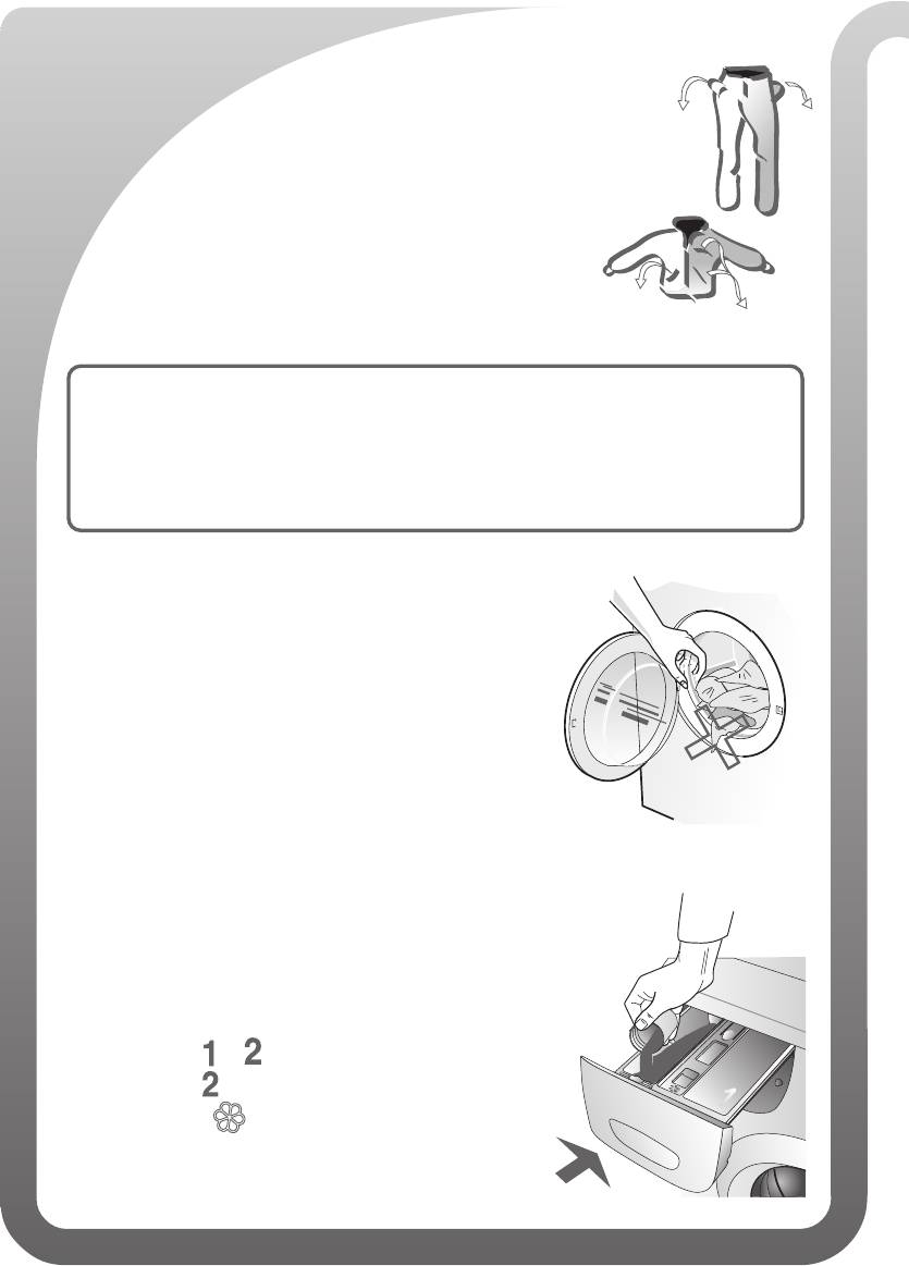
CARICAMENTO DELLA BIANCHERIA
Prima di introdurre la biancheria nel cestello accertarsi che le
tasche siano prive di eventuali oggetti (ad es. chiodi, monete,
aghi, graffette, ecc.) togliere dalle tende gancetti e piombini; que-
sti possono danneggiare sia la biancheria, sia la macchina.
Dividere i capi in base al colore, tenendo presente che
quelli scuri durante i primi lavaggi tendono a stingere.
Il sistema
Easy Logic II riduce automaticamente il tempo di lavag-
gio, i consumi di acqua e di energia in base alla quantità di biancheria
caricata nella macchina. La macchina imposterà automaticamente il
ciclo di lavaggio per il mezzo carico o per carichi incompleti, senza il
bisogno di alcuna regolazione.
Caricare nel cestello la biancheria distesa, senza pres-
sarla.
Capi di diversa grandezza rafforzano l’effetto di la-
vaggio e si distribuiscono meglio durante la cen-
trifugazione.
Chiudere l’oblò esercitando una leggera pressione avendo cura di controllare
che tra sportello e guarnizione non rimangano incastrati capi di biancheria.
CARICAMENTO DEL DETERSIVO
— versare il detersivo nell’apposita vaschetta
— scomparto e per prelavaggio e lavaggio
— scomparto per il solo lavaggio
— scomparto “ “ per ammorbidente o inamidante
— chiudere il cassetto.
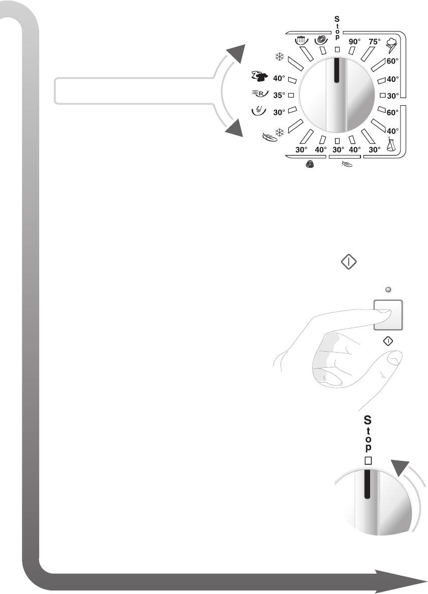
SELETTORE DEI PROGRAMMI
Scegliere il programma e la
temperatura desiderata.
nome modello
per maggiorni informazioni vedi: “TABELLE PROGRAMMI”
• Le opzioni di lavaggio devono essere impostate premendo gli appositi tasti
prima di iniziare il lavaggio e prima di premere il tasto START.
• Avviare il ciclo di lavaggio premendo il tasto START. Il relativo led si
accend erà dopo circa 2-3 secondi, ad indicare che
l’oblò è bloccato e il programma è iniziato.
• Finito il lavaggio il LED START si spegne o lampeggia.
(secondo il modello)
• Ruotare la manopola del programmatore su “STOP”.
• Prima di aprire la macchina disinserire la spina dalla rete
elettrica con mani asciutte.
NB:
• Per interrompere il lavaggio riportare il selettore sulla posizione Stop:
attendere il segnale fi ne.
P
r
i
m
a
di aprire l’oblò attendere 2 minuti per il suo sbloccaggio.
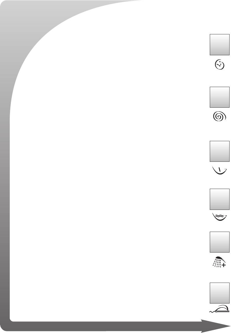
NON TUTTE LE FUNZIONI SONO DISPONIBILI SU TUTTI I MODELLI E SU TUTTI
OPZIONI: SCELTA DELLA MODALITA’ DI LAVAGGIO
Ritardo di partenza
La funzione permette di posticipare l’inizio del programma delle ore
impostate dopo aver premuto il tasto Start (utile anche nelle utenze
con agevolazioni tariffarie d’energia elettrica per fasce orarie).
* Regolazione centrifuga
La lavatrice programma la velocità di centrifuga più idonea per ogni
tipo di tessuto. Con l’apposito pulsante la centrifuga può essere va-
riata od eliminata.
* Nella preparazione alla centrifuga se non avvviene un buon bilanciamento del
carico, per motivi di sicurezza, la macchina riduce automaticamente la velocità
di centrifuga o elimina completamente detta operazione.
Prelavaggio
Premendo questo pulsante, si ottiene un breve prelavaggio con una
temperatura massima di 40°C per una durata di circa 10 minuti.
NB: Se utilizzate questa opzione, il detersivo deve essere versato
anche nell’apposita vaschetta per il prelavaggio.
Lavaggio energico
Questa funzione aumenta l’effi cacia del detergente prolungando il
tempo di lavaggio ma lasciando inalterata la temperatura impostata.
Risciacqui extra
La lavabiancheria è stata progettata per garantire il minor consumo
di acqua. Per pelli sensibili, per zone con acqua molto dolce, o nel
caso si notassero eventuali residui di detersivo a fi ne ciclo, premen-
do questo pulsante la macchina effettuerà un risciacquo aggiuntivo.
Antigrinza
Premendo questo pulsante, al termine del ciclo di lavaggio i panni al-
l’interno della lavabiancheria continuano a ruotare delicatamente per
altri trenta minuti riducendone la sgualcitura. Con questa funzione la
centrifuga di esercizio è di 800 giri.
I
PROGRAMMI (vedi: “TABELLE PROGRAMMI”)
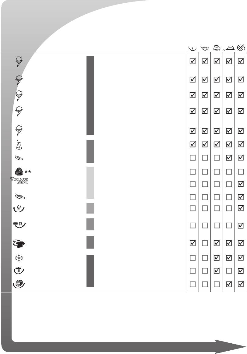
La scelta del programma e della temperatura và eseguita consultando i simboli riportati sulla targhetta
trattamento tessuti (generalmente applicata sul colletto o nella cucitura laterale). Per risparmiare ener—
gia, relativamente al tipo di sporco, si consiglia di utilizzare temperature di lavaggio medio/basse
PROGRAMMI °C CARICO BIANCHERIA FUNZIONI ABILITATE
MAX
Tessuti bianchi in cotone e lino molto sporchi,
COTONE
90°
con macchie anche di natura organica.
Per tessuti resistenti molto sporchi che necessi-
= COTONE
75
°
tano di un’azione antibatterica
# COTONE
60°
Per tessuti e colori resistenti normalmente sporchi
Per camicie, tovaglie, asciugamani, intimo in tes-
COTONE
40°
*
suti e colori delicati normalmente sporchi.
Tessuti con colori delicati, biancheria leggermen-
COTONE
30°
te sporca
SINTETICI
60° — 30°
Tessuti sintetici con colori resistenti molto sporchi
DELICATI
40° — 30°
Tessuti in viscosa e misti delicati.
Pura lana vergine
LANA
40°
LANA
30°
Tessuti in lana e seta lavabili in lavatrice
LANA/
—
Tessuti in lana e seta lavabili in lavatrice
DELICATI
LAVAGGIO
Tessuti lavabili a mano
30°
A MANO
LAVAGGIO
Tessuti in cotone delicato, viscosa e misti delicati
35°
RAPIDO
poco sporchi; durata circa 35/40 Min.
LAVAGGIO
Tessuti in cotone delicato, colorati delicati leg-
40
°
GIORNALIERO
germente sporchi di uso giornaliero
LAVAGGIO
—
Tessuti delicati
FREDDO
RISCIACQUI
—
Per risciacquare e rinfrescare la biancheria
SCARICO
—
Scarico e centrifuga fi nale
CENTRIFUGA
= Programma antibatterico.
# Programma di riferimento per la classifi cazione energetica, in accordo con la norma
EN60456 con velocità massima di centrifuga e pulsante lavaggio energico selezionato.
* Nota per istituti di verifi ca : programma breve con la metà del carico max.
** Il programma “ciclo lana” di questa lavatrice è stato approvato da Woolmark per il lavag-
gio dei capi in lana etichettati “lavabile in lavatrice” che recano i marchi di The Woolmark
Company. Seguire le istruzioni riportate sull’etichetta cucita al capo e le indicazioni fornite
dal fabbricante della lavatrice. (N° cert. M0402-M0403-M0404-M0405).
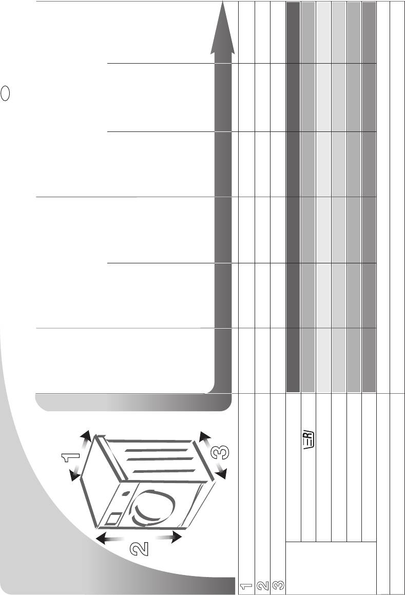
88
108
128
148
168
8.0
4.0
2.0
3.5
4.0
6.0
59.5
85.0
59.0
E / S / L / SP
SB / LB / SC / LC
IT
87
107
127
147
167
7.0
3.5
1.5
3.0
3.5
5.0
59.5
85.0
55.0
E / S / L / SP
SB / LB / SC / LC
461307043 SM2323/08 20/06/2008
86
106
126
146
166
6.0
3.0
1.5
2.5
3.0
4.0
59.5
85.0
55.0
E / S / L / SP
86
106
126
6.0
3.0
1.5
2.5
3.0
4.0
59.5
85.0
46.0*
E / S / L
vedi targhetta caratteristiche
min. 0,05 MPa — max. 1MPa
85
FLSO FLO/FLOI
105
125
5.0
2.5
1.0
2.0
2.5
3.5
59.5
85.0
39.0
E / S / L
CARATTERISTICHE TECNICHE
80
105
3.5
1.7
1.0
1.7
2.0
59.5
85.0
33.0
0.75
E / S / L
FLZO
MODELLO
cotone kg
sint./delic. kg
lana kg
lavaggio a mano kg
lavaggio rapido kg
lavaggio giornaliero kg
Pressione dell’acqua
Larghezza cm
Altezza cm
Profondità cm
Potenza max assorbita /Collegamento elettrico
Carico
max con-
sigliato
durante il
lavaggio
* Profondità al frontalino
GB
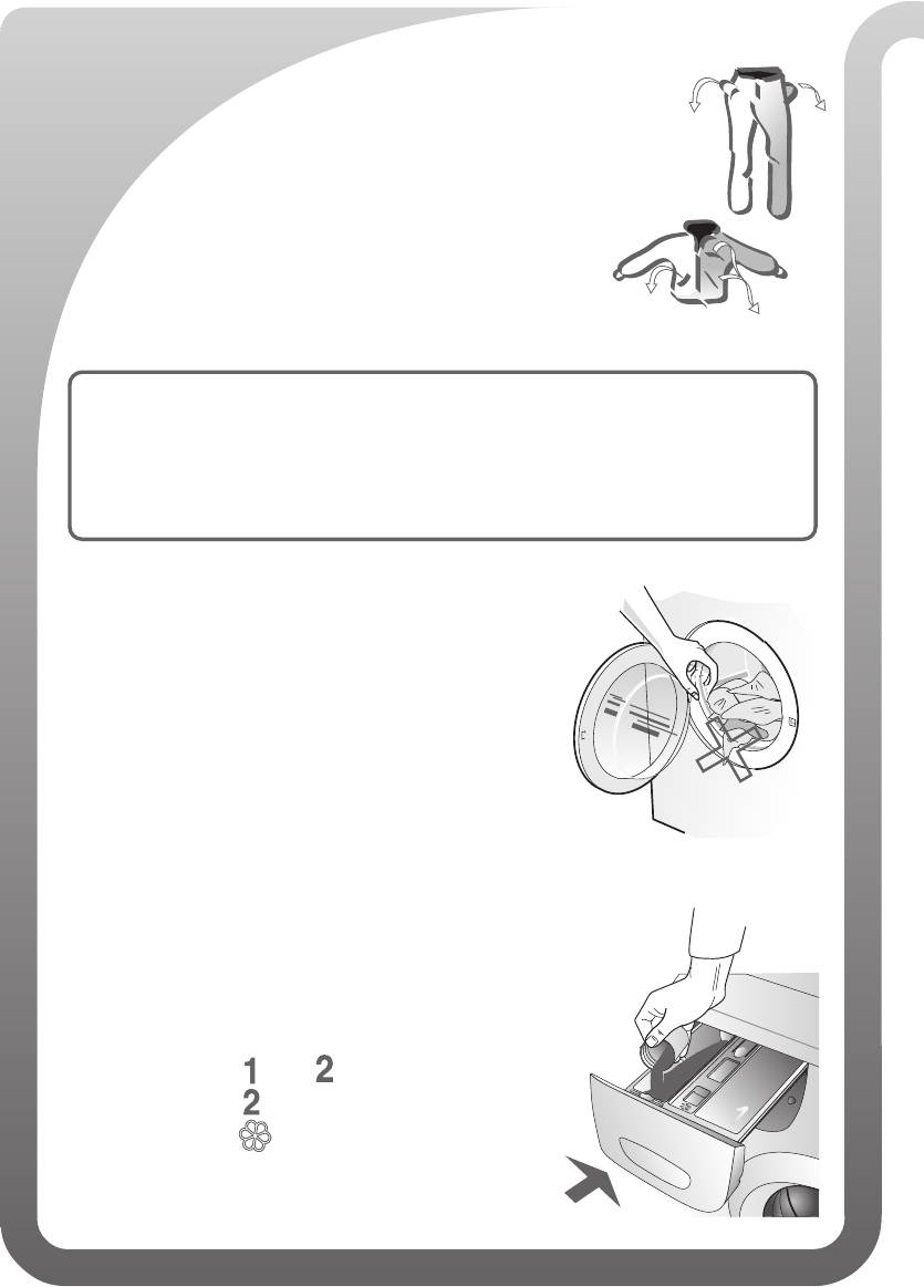
LOADING THE WASHING
Before placing the washing in the drum, make sure that there are
no items left in the pockets (e.g. nails, coins, needles, paper clips,
etc.) and remove hooks and lead weights from curtains. All these
could cause damage to the washing and the washing machine.
Sort the washing according to colour, bearing in mind
that dark colours will tend to run during the fi rst few
washes.
The
Easy Logic II system automatically reduces the wash time and
water and power consumption according to the amount of washing
placed in the drum. The washing machine will automatically pro-
gramme a half-load or incomplete load wash cycle without the need
for any intervention.
Load the washing loosely in the drum without compact-
ing it.
Items of different sizes strengthen the washing ac-
tion and are distributed better during spinning.
Close the door using a light pressure. Check that none of the items have be-
come trapped between the door and the gasket.
LOADING THE DETERGENT
— add the detergent to the appropriate dispenser
— compartments and for prewash and wash
— compartment for wash only
— compartment “ “ for softener or starch
— close the dispenser drawer.
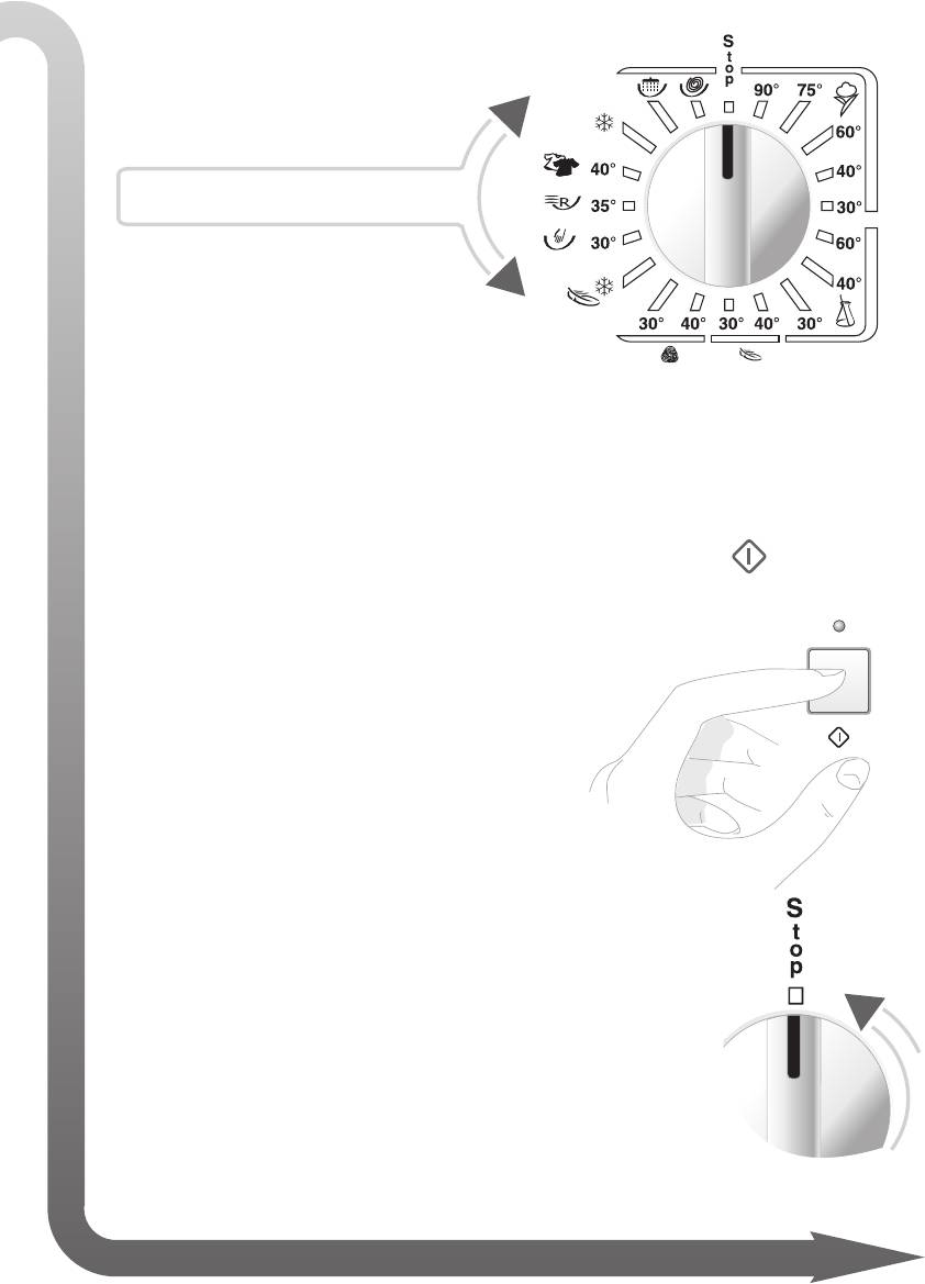
PROGRAMME SELECTOR
Select the programme and
required temperature.
model name
For more information, see:
“PROGRAMME TABLES”
• The wash options must be programmed by pressing the appropriate but-
tons before starting the wash and before pressing the START button.
• To start the drying cycle, press the “START” button. The relative indi-
cator light will light up after approximately 2 -3 seconds
to indicate that the door is locked and the wash pro-
gramme has started.
• At the end of the wash, the START LED with either switch off or fl ash.
(according to the model)
• Rotate the programmer knob to “
STOP”.
NB: Before openi
• Before opening the washing machine door, remove the
plug from the mains electricity socket using dry hands.
• To interrupt the wash cycle, move the selector to the Stop position:
n
g
Wait for the end of wash signal.
t
h
e
d
o
or, wait 2 minutes for the locking mechanism to release.
OPTIONS: SELECTING THE WASH MODE
Delayed start
NOT ALL THE FUNCTIONS ARE AVAILABLE ON ALL PROGRAMMES ON ALL MODEL
This function delays the start of the wash programme by the number
of hours set. The timed delay starts once the Start button has been
pressed. The function is useful for users who use off peak electricity.
* Spin settings
The washing machine programmes the most suitable spin speed for
each type of fabric. The spin speed can be varied or the spin can-
celled by pressing the appropriate button.
* When the washing machine is preparing for the spin cycle, if the washing is not
evenly balanced, for safety reasons, the spin speed is automatically reduced or even
eliminated all together.
Prewash
Press this button to obtain a short prewash of maximum temperature
40°C and approximately 10 minutes duration
NB: When this option is used, detergent must also be added to the
appropriate pre-wash compartment..
Energetic wash
This function increases the effi ciency of the detergent and prolongs
the wash time, leaving the set temperature unaltered.
Extra rinses
The washing machine has been designed to guarantee reduced water
consumption. For sensitive skins, in very soft water areas, or in the case
where detergent residues are noticed at the end of the wash cycle,
pressing this button will add one more rinse to the wash programme.
Anti-crease
When this button is pressed, at the end of the wash cycle, the items
loaded in the washing machine will continue to gently rotate for a
further thirty minutes to reduce creasing. With this function enabled,
the spin speed is 800 rpm.
S
(
see: “PROGRAMME TABLE”)
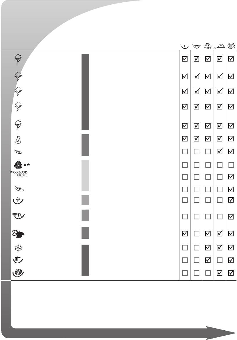
The programme and temperature are selected by referring to the symbols reported on the clothing care
symbols on the items to wash (generally sewn into the collar or side seam). Depending on the type of
soiling, in order to save energy, it is advisable to use medium/low wash temperatures
PROGRAMMES °C MAX WASHING FUNCTIONS ENABLED
LOAD
Heavily soiled white cotton and linen fabrics with
COTTON
90°
organic stains.
For heavily soiled resistant fabrics requiring anti-
= COTTON
75
°
bacterial treatment
# COTTON
60°
Medium soiled colourfast fabrics.
For medium soiled shirts, tablecloths, towels and
COTTON
40°
*
underwear in delicate coloured fabrics.
COTTON
30°
Lightly soiled delicate coloured fabrics.
60° — 30°
Heavily soiled colourfast synthetic fabrics.
SYNTHETICS
DELICATES
Viscous and mixed delicate fabrics.
40° — 30°
WOOL
40°
Pure new wool
WOOL
30°
Machine washable wool and silk
WOOL /
—
Machine washable wool and silk
DELICATES
HAND
30°
Hand washable fabrics
WASH
Delicate cotton, viscous and mixed delicate fab-
QUICK
35°
rics lightly soiled of approximately 35/40 minutes
WASH
duration.
DAILY
Delicate cotton, delicate coloured fabrics lightly
40
°
WASH
soiled by daily use
COLD
—
Delicate fabrics
WASH
RINSES
—
To rinse and refresh the washing.
DRAIN
—
Drain and fi nal spin.
SPIN
= Antibacterial programme.
# Reference program for energy classifi cation purposes according to standard EN 60456 with
maximum spin speed and energetic wash function selected.
* Note for test centres: Short programme with half max. load.
** The “wool cycle” programme of this washing machine has been approved by Woolmark
for washing items labelled “machine washable wool” and bearing The Woolmark Company
symbols. Follow the instructions reported on the label sewn into the clothing item and those
supplied by the washing machine manufacturer. (Cert. n° M0402-M0403-M0404-M0405).
Аннотации для Стиральной Машиной Ardo FLSO85E в формате PDF
Топ 10 инструкций
Другие инструкции
Перейти к контенту
 Ищите инструкцию стиральной машины ardo tl810e , мы сохранили все русские инструкции на нужном вам языке и вы можете прочитать их прямо на этой странице или скачать себе и распечатать необходимую страницу.
В комментариях вы можете задать свой вопрос мастеру, или поделиться решением своей проблемы с другими читателями нашего портала.
Подробная инструкция стиральной машины марки ardo поможет вам решить вопросы с техническими характеристиками этой машины, какое количество белья можно загружать в эту стиральную машину, сколько и куда сыпать порошок для стирки, а также установки и подключение, а также как пользоваться модулем управления стиральной машины
Инструкция по использованию стиральной машины Ardo tl800e
Скачать (PDF, 657KB)
Также мы сделали ссылку для вас, по которой вы бесплатно можете себе скачать на компьютер эту инструкцию для фронтальной стиральной машины Ardo tl800e
Если вы будете придерживаться рекомендаций из данной статьи по использованию стиральной машины, то непременно увеличите срок её эксплуатации, а также получите удовольствие от стирки и использования этой домашней помощницы!
Видео стиральной данной модели Ardo tl800e
ТОП магазинов стиральных машин и бытовой техники:
- holodilnik.ru – Недорогой магазин бытовой техники.
- techport.ru — выгодный современный интернет магазин бытовой техники
- ru.aliexpress.com— запчасти для стиральных машин
( 1 оценка, среднее 5 из 5 )

Здравствуйте, я Роман, мастер стиральных машин с опытом более 13 лет! Веду этот сайт, Делюсь опытом и помогаю советом. Если сайт был полезен, ваша лучшая благодарность ваш опыт в комментарии!
Для вызова специалиста позвоните в мастерскую «РемБытТех» по телефонам (с 8 до 22.00):
+7 (495) 215 – 14 – 41
+7 (903) 722 – 17 – 03
Либо заполните онлайн-форму на сайте (в любое время суток). При оформлении заявки на ремонт сообщите:
- Марку и модель вашего агрегата.
- Характер поломки. Например, стиральная машина медленно набирает воду или крутит барабан в одну сторону.
- Подходящие день и время ремонта.
- Ваши имя, адрес, телефон.
В день ремонта мастер позвонит вам по указанному номеру, чтобы согласовать точное время приезда.
Требуется профессиональный ремонт Ardo TL 810 EX? Звоните в «РемБытТех»! Опытные мастера вернут вашу стиральную машину в рабочее состояние прямо на дому при вашем присутствии. После ремонта на все работы и новые запчасти будет предоставлена гарантия до 2 лет. Выезд мастера – уже в течение 24 часов после обращения!
made for you.
QUICK REFERENCE PROGRAMMES
|
IT |
ITALIANO |
3-6 |
||
|
GB |
ENGLISH |
7-10 |
||
|
DE |
DEUTSCH |
11-14 |
||
|
FR |
FRANÇAIS |
15-18 |
||
|
ES |
ESPAÑOL |
19-22 |
||
|
PL |
POLSKI |
23-26 |
||
|
CZ |
ČESKY |
27-30 |
||
|
SK |
SLOVENSKY |
31-34 |
||
|
UA |
УКРАЇНСЬКА |
35-38 |
||
|
RU |
РУССКИЙ |
39-42 |
||
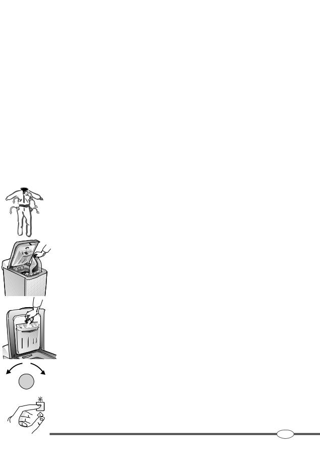
|
GUIDA AL LAVAGGIO |
3 |
|
T S A |
|
B C D E F |
G H |
I |
|||||||||||
|
Vaschetta detersivo: |
Pannello comandi: |
F |
Pulsante skin care |
||||||||||
|
Prelavaggio |
A LED Fasi di lavaggio |
G |
Pulsante easy iron |
||||||||||
|
Lavaggio |
B Pulsante partenza ritardata |
H Pulsante start |
|||||||||||
|
C Pulsante centrifuga |
I |
Manopola selettore programmi |
|||||||||||
|
Ammorbidente |
|||||||||||||
|
D Pulsante prelavaggio |
S |
LED giri centrifuga |
|||||||||||
|
Candeggiante |
E Pulsante turbo |
T |
LED partenza ritardata |
||||||||||
LAVARE IN MODO CORRETTO
Prima di mettere in funzione la lavabiancheria assicurarsi che l’installazione sia stata eseguita correttamente come riportato nel libretto di istruzioni.
Utilizzo quotidiano
1.Prima di inserire i capi nella lavabiancheria vuotare le tasche da oggetti duri e appuntiti (chiodi, viti, monete, spille, sassi) che potrebbero danneggiare la macchina e gli indumenti.
2.Aprire il coperchio superiore della lavatrice esercitando una leggera pressione verso il basso prima di alzarlo.
3.Aprire gli sportelli del cestello premendoli leggermente con una mano, mentre con l’altra premere il pulsante d’apertura.
4.Per migliorare le performance di lavaggio introdurre la biancheria distesa senza comprimerla evitando di sovraccaricare la macchina. Un carico intero di tessuti particolarmente assorbenti, ad esempio accappatoi ed asciugamani di spugna, può sbilanciare la macchina durante la fase di centrifuga. Il sistema automatico di bilanciamento del carico dispone il bucato nella maniera più omogenea possibile ed imposta l’ottimale velocità di centrifuga per ridurre al minimo l’eventuale presenza di vibrazioni.
5.Chiudere gli sportellini del cestello facendo attenzione che siano ben agganciati.
6.Dosare la giusta quantità di detersivo nell’apposita vaschetta II. Se si desidera attivare l’opzione
prelavaggio aggiungere il detergente nella vaschetta I. Per l’ammorbidente e il candeggiante utilizzare la vaschetta contraddistinta dai simboli  e
e  .
.
7.Selezionare il programma di lavaggio adatto alla tipologia di tessuti tramite la manopola I seguendo le indicazioni riportate nella tabella programmi. Uno dei LED della barra delle funzioni si accende per indicare la fase con cui il programma avrà inizio. L’ accensione del LED end indica la fine del ciclo.
8.Premendo il tasto C è possibile impostare una velocità di centrifuga differente da quella proposta dal programma selezionato. Il tasto B consente di posticipare l’avvio del ciclo di lavaggio fi no a un massimo di 8 ore. Entrambi i valori vengono indicati dai rispettivi LED.
9.Tramite i pulsanti D, E, F e G è possibile selezionare le funzioni supplementari. Le opzioni scelte vengono indicate dall’ accendersi dei relativi LED. La durata del ciclo di lavaggio varia in funzione delle opzioni attivate.
10.Premere il pulsante start H per avviare il ciclo di lavaggio. Dopo alcuni secondi il LED start rimanendo costantemente acceso indica che il programma è avviato.
11.La fine del ciclo di lavaggio è indicata dall’accensione del LED end.
Riportare la manopola I in posizione di stop, aprire il coperchio superiore, gli sportellini del cestello e prelevare la biancheria.
12.In qualsiasi momento è possibile annullare il programma riportando la manopola I in posizione di stop.
IT
SM2734
LED INDICATORI DELLE FASI DI PROGRAMMA: L’ accensione progressiva dei LED permette di sapere in ogni momento quale fase del programma la lavabiancheria sta eseguendo.
PARTENZA RITARDATA: Questa funzione permette di posticipare la partenza del ciclo di lavaggio fi no ad un massimo di 8 ore. Premere ripetutamente il pulsante B fi n quando il LED acceso indicherà il ritardo di partenza desiderato. Il LED T lampeggerà fi no all’avvio del ciclo di lavaggio.
CENTRIFUGA REGOLABILE: Premendo il pulsante C la velocità di centrifuga può essere regolata in funzione del programma di lavaggio scelto e della tipologia di tessuti. Il LED acceso indicherà il valore di velocità selezionato. Per escludere la centrifuga a fi ne ciclo selezionare l’icona “ ”
”
N.B.: La velocità massima di centrifuga varia in funzione del modello. La velocità abbinata ad ogni programma è quella consigliata.
PRELAVAGGIO: Per effettuare il prelavaggio premere il pulsante D ed aggiungere il detersivo nell’apposita vaschetta I. La lavabiancheria effettua un prelavaggio a 40°C max. Il Prelavaggio è indicato nel caso di indumenti sporchi di polvere, terra, sabbia o in presenza di macchie particolarmente resistenti. Vedere la tabella programmi per ulteriori informazioni.
TURBO: Premere il pulsante turbo E per ridurre il tempo di lavaggio. I parametri di funzionamento vengono regolati automaticamente per garantire l’effi cacia di lavaggio e per consentire un risparmio di tempo. Vedere la tabella programmi per ulteriori informazioni.
SKIN CARE: Premendo il pulsante F si attiva la funzione skin care, che effettua un risciacquo aggiuntivo. L’opzione è raccomandata per pelli particolarmente sensibili agli enzimi contenuti nei detergenti.
EASY IRON: Attivando l’opzione easy iron tramite il pulsante G, la lavabiancheria regola i parametri di lavaggio per diminuire la formazione di pieghe facilitando le operazioni di stiratura. La velocità di centrifuga viene impostata automaticamente a 500 giri/min.
START: Durante la fase di selezione dei programmi e delle opzioni di lavaggio il LED start resta spento. Per confermare le scelte ed avviare il ciclo di lavaggio premere il pulsante H. Il LED si accende.
IT
SM2734
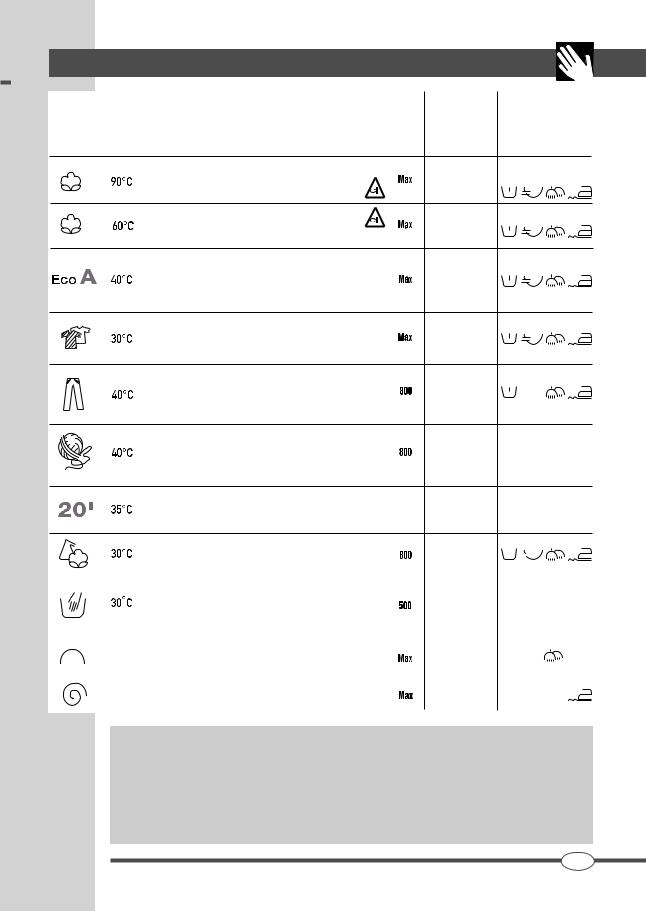
|
TABELLA PROGRAMMI |
5 |
||||
|
Massima |
Carico massimo |
||||
|
velocità di |
in funzione del |
Opzioni |
|||
|
Programmi |
Tipologia di bucato |
centrifuga |
modello e del |
||
|
(giri/min) |
programma |
Attivabili |
|||
|
Simbolo |
Temperatura |
scelto (kg) |
|||
|
Bianchi in lino e cotone molto sporchi, con macchie anche di natura |
|||||
|
organica. |
6.0 |
T |
|||
|
In questo programma è possibile l’utilizzo del candeggiante |
|||||
|
Bianchi e colorati resistenti in lino e cotone. |
|||||
|
In questo programma è possibile l’utilizzo del candeggiante |
6.0 |
T |
|||
|
Programma di riferimento in accordo con la norma EN60456 |
|||||
|
Lo speciale programma EcoA assicura i migliori risultati in classe |
|||||
|
A di efficacia di lavaggio, a soli 40°C, con il massimo risparmio di |
6.0 |
T |
|||
|
energia elettrica. Programma di riferimento per associazioni |
|||||
|
consumatori. |
|||||
|
Il programma coloured permette di lavare insieme capi di diverso |
6.0 |
T |
|||
|
colore; si possono lavare in tutta sicurezza biancheria chiara e scura |
senza correre alcun rischio di scolorimenti.
Lo speciale programma jeans effettua un lavaggio delicato a 40°C
che si prende cura di tutte le fibre in denim e allo stesso tempo ne 3.0 previene lo scolorimento rispettando i colori. I vestiti in tessuto
denim delavé rimarranno sempre come nuovi.
Il programma lana è ideale per il lavaggio dei capi delicati che
riportano in etichetta la dicitura «lavabile in lavatrice». 1.5 Garantisce la cura dei colori e la consistenza originale degli indumenti
nel tempo.
Il ciclo di lavaggio express 20′ è adatto per rinfrescare, in soli 20
minuti, la biancheria leggermente sporca. Express 20′ ti permette di  3.0 risparmiare tempo prezioso effettuando un ciclo di lavaggio a 35°C.
|
Lo speciale programma mix consente di lavare insieme tessuti di |
3.0 |
T |
||||||||||||
|
diversa natura (cotone, sintetici, misti) con un risultato perfetto. |
||||||||||||||
|
I capi delicati richiedono una cura particolare e normalmente si |
||||||||||||||
|
lavano a mano. |
1.0 |
|||||||||||||
|
Lo specifico lavaggio a mano ti assicura la massima delicatezza nel |
||||||||||||||
|
trattamento degli indumenti. |
||||||||||||||
|
Il programma risciacqui è utile per risciacquare biancheria lavata a |
6.0 |
|||||||||||||
|
mano o rinfrescare indumenti riposti per lungo tempo. |
||||||||||||||
|
La velocità della centrifuga è regolabile per adattarsi a tutti i tipi di |
6.0 |
|||||||||||||
|
tessuti. |
Controllo antisbilanciamento del carico in centrifuga:
Questa lavatrice è dotata di uno speciale sistema di controllo elettronico per il corretto bilanciamento del carico. Il sistema, prima di ogni centrifuga, fa in modo che i panni si dispongano nel cestello nel modo più uniforme possibile. In caso di distribuzione irregolare della biancheria, per motivi di sicurezza, la velocità di centrifugazione fi nale verrà ridotta e in casi di alto sbilanciamento del carico non verrà effettuata.
IT
SM2734

|
6 |
CARATTERISTICHE TECNICHE |
EASY LOGIC: Il sistema EASY LOGIC regola automaticamente il tempo di lavaggio, i consumi di acqua e di energia in base alla reale quantità di biancheria caricata nella macchina. La funzione 1/2 carico è superflua perchè il sistema EASY LOGIC imposta automaticamente i parametri di lavaggio.
SMART STOP La funzione smart stop consente al termine del ciclo di lavaggio il corretto posizionamento del cestello rendendo più agevole l’estrazione del bucato.
E’ comunque possibile che in presenza di particolari condizioni di carico il posizionamento risulti impreciso e sia quindi necessario far ruotare parzialmente il cestello.
|
TLN126S |
TLN106S |
||||||||||
|
W/B/A |
W/B/A |
||||||||||
|
40.0 |
40.0 |
||||||||||
|
90.0 |
90.0 |
||||||||||
|
60.0 |
60.0 |
||||||||||
|
1200 |
1000 |
||||||||||
|
Carico massimo |
6.0 |
6.0 |
|||||||||
NOTE
………………………………………………………………………………………………………………………………………………………………………………………………………………………………………………………………..
………………………………………………………………………………………………………………………………………………………………………………………………………………………………………………………………..
………………………………………………………………………………………………………………………………………………………………………………………………………………………………………………………………..
………………………………………………………………………………………………………………………………………………………………………………………………………………………………………………………………..
………………………………………………………………………………………………………………………………………………………………………………………………………………………………………………………………..
………………………………………………………………………………………………………………………………………………………………………………………………………………………………………………………………..
………………………………………………………………………………………………………………………………………………………………………………………………………………………………………………………………..
………………………………………………………………………………………………………………………………………………………………………………………………………………………………………………………………..
………………………………………………………………………………………………………………………………………………………………………………………………………………………………………………………………..
………………………………………………………………………………………………………………………………………………………………………………………………………………………………………………………………..
………………………………………………………………………………………………………………………………………………………………………………………………………………………………………………………………..
………………………………………………………………………………………………………………………………………………………………………………………………………………………………………………………………..
………………………………………………………………………………………………………………………………………………………………………………………………………………………………………………………………..
………………………………………………………………………………………………………………………………………………………………………………………………………………………………………………………………..
IT
SM2734

|
B C D E F |
G H |
I |
|||||||||||
|
Detergent dispenser: |
Control panel: |
F Skin Care Button |
|||||||||||
|
Prewash |
A Wash Phases LEDS |
G Easy Iron Button |
|||||||||||
|
Wash |
B Delayed Start Button |
H Start button |
|||||||||||
|
Softener |
C Spin button |
I Programme selector knob |
|||||||||||
|
D Prewash button |
S Spin Speed LEDS |
||||||||||||
|
Bleach |
|||||||||||||
|
E Turbo button |
T Delayed Start LEDS |
||||||||||||
CORRECT WASHING PROCEDURE
Before using the washing machine, make sure that it has been installed correctly as reported in the instruction book.
Daily use
1. Before placing the laundry in the washing machine, empty the pockets of any hard or sharp objects (nails, screws, coins, pins, stones) which could damage the machine and ruin the clothing.
2.Open the top of the washing machine, lightly pressing downwards before lifting it.
3.Open the doors of the drum, pressing them lightly with one hand, while pressing the opening button
with the other.
4. To improve washing performance, load the laundry loosely without pressing on it, in order to avoid overloading the machine. An entire load of particularly absorbing fabrics, such as sponge towels and bathrobes, can unbalance the machine during the spin cycle. The automatic load-balancing system places the laundry in the most homogeneous way possible and sets the optimal spin speed to reduce vibrations to a minimum.
5.Close the drum doors making sure they are well hooked.
6.Dose the right amount of detergent in the appropriate chamber II. Add extra detergent in the chamber
I if you want to activate the prewash option. For softeners and bleaches, use the chamber marked with the symbols  and
and .
.
7. Select the washing program suitable for the type of fabrics using the I knob, following the instruc-
tions carried on the program table. One of the function bar LEDs will turn on to indicate the phase
with which the program will start. When the end LED turns on, the cycle is over.
8. Pressing C, it is possible to set a different spin speed from the one proposed by the selected program. The B key allows postponing the start of the wash cycle up to a maximum of 8 hours.
Both values are indicated by the respective LEDs.
9. With the D, E, F and G buttons, supplementary functions can be selected. The options chosen
are indicated by their relative LEDs turning on. The duration of the wash cycle varies depending
on the options activated.
10. Press the H button to start the wash cycle. After a few seconds, the start LED will stay lit constantly,
indicating that the program has started.
11. The end of the wash cycle is indicated when the end LED turns on.
Place the I knob back to the stop position, open the top cover and the drum doors and take the
laundry out.
12. The program can be cancelled at any time by turning the I knob back to the stop position.
GB
SM2734
PROGRAMME PHASE INDICATOR LEDS: The progressive lighting up of the LEDS will indicate the programme phase the washing machine is currently effecting.
DELAYED START: This function allows the start of the wash cycle to be delayed by up to 8 hours. Press button B repeatedly until the required delay time is indicated by the appropriate LED. LED T will fl ash until the wash cycle starts.
ADJUSTABLE SPIN: Button C can be pressed to change the spin speed in line with the wash programme selected and the type of fabrics. The selected spin speed will be indicated by the lit LED. To disable the end of cycle spin, select icon “ ”
”
N.B.: The maximum spin speed varies according to the model. The spin speed selected by the programme is that recommended.
PRE-WASH: To carry out a prewash, press button D and add detergent to the appropriate compartment I.The washing machine will carry out a prewash at 40°C max. A Prewash is recommended for items soiled with dust, soil, sand or with particularly resistant stains. See the Programme Table for further information.
TURBO: To reduce the wash time, press the Turbo button E.The operating parameters are automatically regulated to ensure an effective wash and to save time. See the Programme Table for further information.
SKIN CARE: Pressing the button F activates the skin care function, which carries out an extra rinsing. The option is recommended for skins particularly sensitive to the enzymes contained in detergents.
EASY IRON: Press button G to select the Easy Iron option.The washing machine will regulate the wash parameters to reduce the formation of creases and make ironing easier. The spin speed is set automatically at 500 rpm.
START: During the phase for selecting programs and washing options, the start LED stays off. To confi rm the selections and start the wash cycle, press “Start” button H. The LED will light up.
GB
SM2734
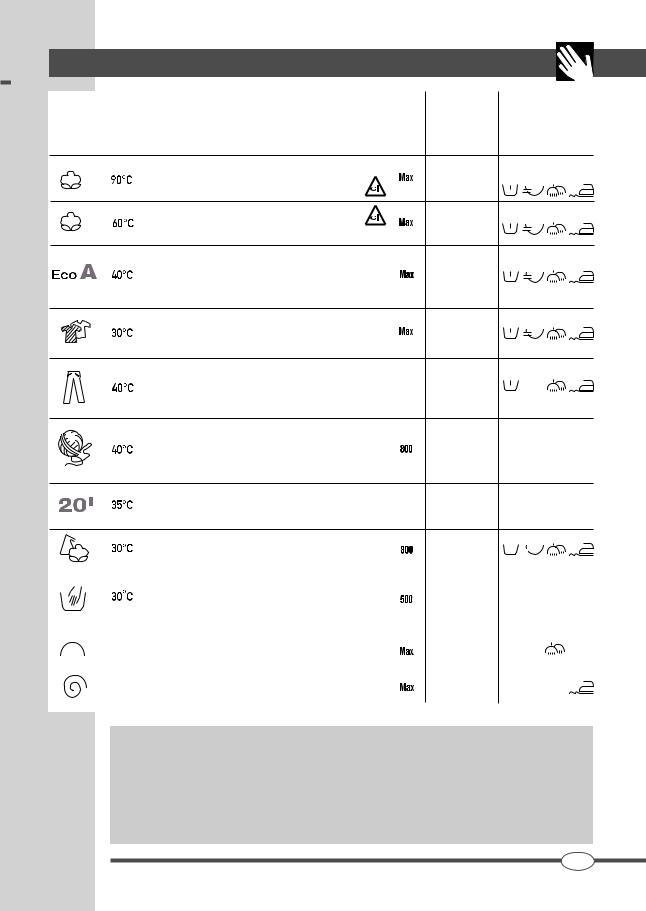
|
PROGRAMME TABLE |
9 |
|||||
|
Max. spin |
Maximum load |
|||||
|
speed |
depending on the |
|||||
|
Programmes |
Type of washing |
(rpm) |
model and the |
Options |
||
|
selected |
||||||
|
Symbol |
Temperature |
program |
||||
|
Heavily soiled white linen and cotton fabrics with organic stains. |
||||||
|
Bleach can be used with this program. |
6.0 |
T |
||||
|
Resistant white and coloured fabrics in linen and cotton. |
||||||
|
Bleach can be used with this program. |
6.0 |
T |
||||
|
Reference programme according to standard EN 60456. |
||||||
|
The special EcoA programme guarantees the best possible results |
T |
|||||
|
of a Class A wash efficiency at only 40°C, with maximum energy |
6.0 |
|||||
|
saving. Reference programme for Consumer Associations. |
||||||
|
The Coloured programme allows mixed light and dark colours to be |
6.0 |
T |
||||
|
safely washed without any risk of discolouring. |
||||||
The special Jeans programme carries out a delicate wash at 40°C,
which looks after the Denim fibres and at the same time prevents  3.0 discolouring. Clothing in faded Denim fabrics will remain as-new.
The Wool programme is ideal for washing particularly delicate items labelled as being “machine washable”.
The programme looks after the colours and retains the original 1.5 texture of the items over time.
The Express Wash 20′ programme is suitable for refreshing lightly
soiled items in only 20 minutes. Express 20′ means saving precious  3.0 time by performing a wash cycle at 35°C.
|
The special Mix programme allows different fabrics (cotton, synthetics, |
3.0 |
T |
|||||||||
|
mixed) to be washed together with perfect results. |
|||||||||||
|
Delicate items require extra care and are normally washed by |
|||||||||||
|
hand. |
1.0 |
||||||||||
|
The Hand Wash function treats the wash items with utmost |
|||||||||||
|
delicacy. |
|||||||||||
|
The Rinse programme is useful for rinsing hand-washed items or |
6.0 |
||||||||||
|
for refreshing items that have not been used for a long time. |
|||||||||||
|
The spin speed can be regulated for all types of fabrics. |
6.0 |
||||||||||
Anti-imbalance control of the spinning load:
This washing machine is supplied with a special electronic control system for correct load balancing. Before spinning, the system has the articles in the drum arranged as uniformly as possible.
If the laundry distribution is irregular, the fi nal spin speed will be reduced for safety purposes. For highly unbalanced loads, it will not spin at all.
GB
SM2734
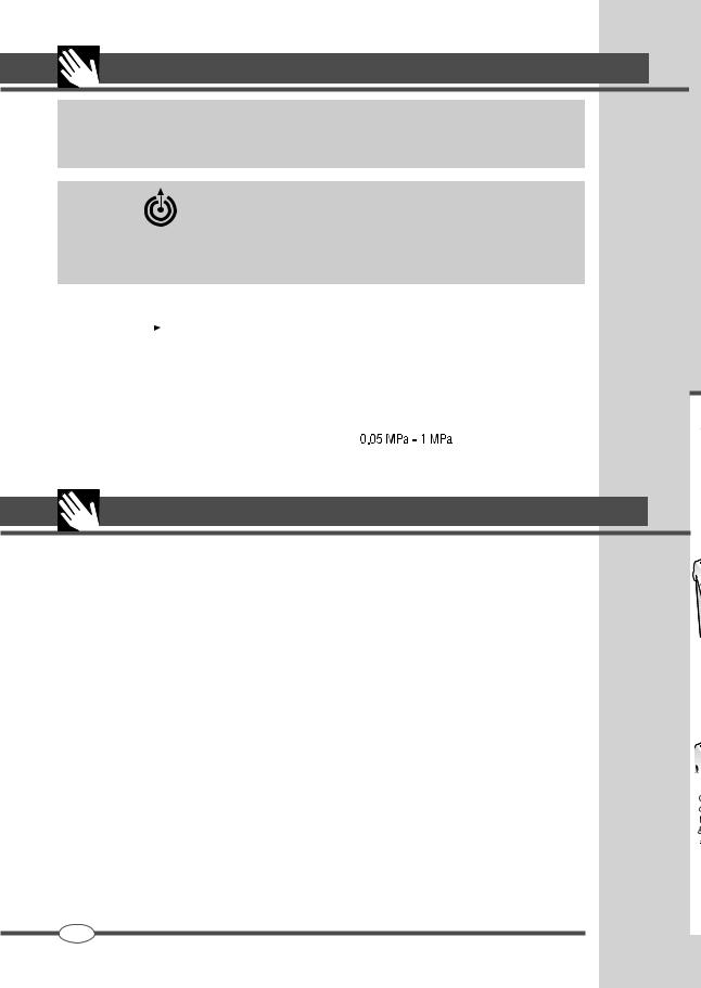
|
10 |
TECHNICAL CHARACTERISTICS |
EASY LOGIC: The EASY LOGIC system automatically regulates the wash time and water and power consumption according to the actual amount of washing placed in the drum. The ½ load function is therefore redundant in that the EASY LOGIC system automatically sets the wash parameters.
SMART STOP : The smart stop function allows the drum to be positioned correctly at the end of the wash cycle, making it easier to take the laundry out.
However, for particular load conditions, the positioning could be imprecise, making it necessary to turn the drum partially.
|
MODEL: |
TLN126S |
TLN106S |
|||||||
|
W/B/A |
W/B/A |
||||||||
|
Width (cm) |
40.0 |
40.0 |
|||||||
|
Dimensions Height (cm) |
90.0 |
90.0 |
|||||||
|
Depth (cm) |
60.0 |
60.0 |
|||||||
|
Max. spin speed (rpm) |
1200 |
1000 |
|||||||
|
Max. load |
6.0 |
6.0 |
|||||||
|
Water pressure |
|||||||||
|
Electrical connection |
see rating plate |
NOTES
………………………………………………………………………………………………………………………………………………………………………………………………………………………………………………………………..
………………………………………………………………………………………………………………………………………………………………………………………………………………………………………………………………..
………………………………………………………………………………………………………………………………………………………………………………………………………………………………………………………………..
………………………………………………………………………………………………………………………………………………………………………………………………………………………………………………………………..
………………………………………………………………………………………………………………………………………………………………………………………………………………………………………………………………..
………………………………………………………………………………………………………………………………………………………………………………………………………………………………………………………………..
………………………………………………………………………………………………………………………………………………………………………………………………………………………………………………………………..
………………………………………………………………………………………………………………………………………………………………………………………………………………………………………………………………..
………………………………………………………………………………………………………………………………………………………………………………………………………………………………………………………………..
………………………………………………………………………………………………………………………………………………………………………………………………………………………………………………………………..
………………………………………………………………………………………………………………………………………………………………………………………………………………………………………………………………..
………………………………………………………………………………………………………………………………………………………………………………………………………………………………………………………………..
………………………………………………………………………………………………………………………………………………………………………………………………………………………………………………………………..
………………………………………………………………………………………………………………………………………………………………………………………………………………………………………………………………..
GB
SM2734

|
LEITFADEN ZUM WASCHEN |
11 |
|
T S A |
|
B C D E F |
G H |
I |
|||||||||||
|
Waschmittelfach: |
Bedienfeld: |
F Taste Skin Care |
|||||||||||
|
Vorwäsche |
A LED Waschphasen |
G Taste Easy Iron |
|||||||||||
|
Hauptwäsche |
B Taste für Startverzögerung |
H Start-Taste |
|||||||||||
|
I Programmwähler |
|||||||||||||
|
Weichspüler |
C Schleuder-Taste |
||||||||||||
|
S LED Schleuderdrehzahl |
|||||||||||||
|
D Taste für Vorwäsche |
|||||||||||||
|
Bleichmittel |
T LED für Startverzögerung |
||||||||||||
|
E Turbo-Taste |
|||||||||||||
RICHTIGES WASCHEN
Vor Inbetriebsetzung der Waschmaschine muss sichergestellt werden, dass die Installation korrekt und entsprechend der Gebrauchsanweisung erfolgt ist.
Täglicher Gebrauch
1.Bevor die Kleidungsstücke in die Waschmaschine gegeben werden, die harten und spitzen Gegenstände (Nägel, Schrauben, Münzen, Nadel, Steine, etc.), die die Maschine und die Kleidungsstücke beschädigen könnten, aus den Taschen entfernen.
2.Oberen Deckel der Waschmaschine öffnen, indem ein leichter Druck ausgeübt wird, um ihn zu heben.
3.Die Klappen der Trommel öffnen, indem sie leicht mit einer Hand gedrückt werden, während mit der anderen Hand die Öffnungstaste gedrückt wird.
4.Zum Verbessern der Waschleistung die Wäsche ausgebreitet, ohne sie zusammen zu drücken, in die Maschine geben, was ein Überladen der Maschine vermeiden hilft. Eine komplette Ladung mit Geweben, die besonders saugfähig sind, wie zum Beispiel Bademäntel und Handtücher aus Frottee, kann die Maschine während de Schleuderphase aus dem Gleichgewicht bringen. Das automatische Auswuchtsystem der Ladung verteilt die Wäsche gleichmäßiger und stellt die ideale Geschwindigkeit der Zentrifuge ein, um eventuelle Vibrationen auf ein Minimum zu reduzieren.
5.Klappen der Trommel schließen und darauf achten, dass sie richtig einrasten.
6.Die richtige Menge Waschmittel in das entsprechende II Fach dosieren. Wenn man die Vorwasch-
option aktivieren möchte, Waschmittel in das entsprechende I Fach geben. Für Weichspüler und Bleichmittel das durch die Symbole  und
und gekennzeichnete Fach verwenden.
7.Mittels des Knopfes I das für das Gewebe geeignete Waschprogramm auswählen und die in der Tabelle der Programme aufgeführten Angaben beachten. Eine der LED des Funktionsbalkens schaltet sich ein, um die Phase anzuzeigen, mit der das Programm beginnen wird. Das Einschalten der LED end zeigt das Ende des Waschgangs an.
8.Durch Drücken der Taste C kann eine andere Schleudergeschwindigkeit, als die vom ausgewählten Programm vorgeschlagene, eingestellt werden. Die Taste B ermöglicht es, den Start des Waschgangs um bis zu 8 Stunden zu verschieben. Beide Werte werden von den entsprechenden LED angezeigt.
9.Mittels der Tasten D, E, F und G ist es möglich, die Zusatzfunktionen auszuwählen. Die gewählten Optionen werden durch das Einschalten der entsprechenden LEDs angezeigt. Die Dauer des Waschgangs hängt von den gewählten Optionen ab.
10.Die Start-Taste H drücken, um den Waschgang zu aktivieren. Nach einigen Sekunden zeigt das LED start, dadurch dass es eingeschaltet bleibt, an, dass das Programm gestartet wurde.
11.Das Ende des Waschgangs wird durch das Einschalten der LED end angezeigt.
Den Knopf I wieder auf die Position stop bringen, den oberen Deckel öffnen, die Klappen der Trommel und die Wäsche entnehmen.
12.Das Programm kann jederzeit neu eingestellt werden, indem der Knopf I auf die Position stop gestellt wird.
DE
SM2734

LED-ANZEIGEN DER PROGRAMMPHASEN: Das progressive Einschalten der LEDs zeigt jederzeit an, in welcher Programmphase sich die Waschmaschine befi ndet.
STARTVERZÖGERUNG: Mit dieser Taste kann der Start des Waschgangs um bis maximal 8 Stunden verzögert werden. Die Taste B mehrmals drücken, bis die eingeschaltete LED die gewünschte Verzögerungszeit sichtbar wird. Das Symbol T blinkt, bis der Waschgang angelaufen ist.
EINSTELLBARE SCHLEUDERDREHZAHL: Mit derTaste C kann die Schleuderdrehzahl je nach gewähltem Waschprogramm und Art der Wäsche reguliert werden. Die eingeschaltete LED zeigt die selektierte Schleuderdrehzahl an. Um das Schleudern am Ende eines Waschgangs auszuschließen, das Symbol “  ” selektieren.
NB: Die maximale Schleuderdrehzahl hängt vom Modell ab. Die den einzelnen Programmen zugeordnete Schleuderdrehzahl ist der empfohlene Wert.
VORWÄSCHE: Für die Vorwäsche die Taste D drücken und Waschmittel in das Einspülfach I füllen. Die Waschmaschine führt eine Vorwäsche bei max. 40°C durch. Die Vorwäsche empfi ehlt sich bei stark mit Staub, Erde, Sand verschmutzter oder fl eckiger Wäsche. Für weitere Informationen siehe Programm-Tabelle.
TURBO: Die Taste für Turbo E drücken, um die Dauer des Waschgangs abzukürzen. Damit die Waschwirkung gewährleistet und Zeit eingespart wird, werden die Betriebsparameter automatisch reguliert. Für weitere Informationen siehe ProgrammTabelle.
SKIN CARE: Durch Drücken der Taste F wird die Funktion Skin Care aktiviert, bei der ein zusätzlicher Spülgang ausgeführt wird. bei der ein zusätzlicher Spülgang ausgeführt wird. Diese Option empfi ehlt sich für Personen deren Haut besonders gegen die in Waschmitteln enthaltenen Enzyme empfi ndlich ist.
EASY IRON: Mit der Taste G wird die Option Easy Iron aktiviert, welche die Betriebsparameter der Waschmaschine so reguliert, dass die Wäsche weniger knittert, wodurch das Bügeln erleichtert wird. Die Schleuderdrehzahl wird automatisch auf 500 U/min eingestellt.
DÉPART : Pendant la phase de sélection des programmes et des options de lavage la DEL start reste éteinte. Pour confi rmer les choix et faire démarrer le cycle de lavage, presser la touche H. La DEL s’allume.
DE
SM2734
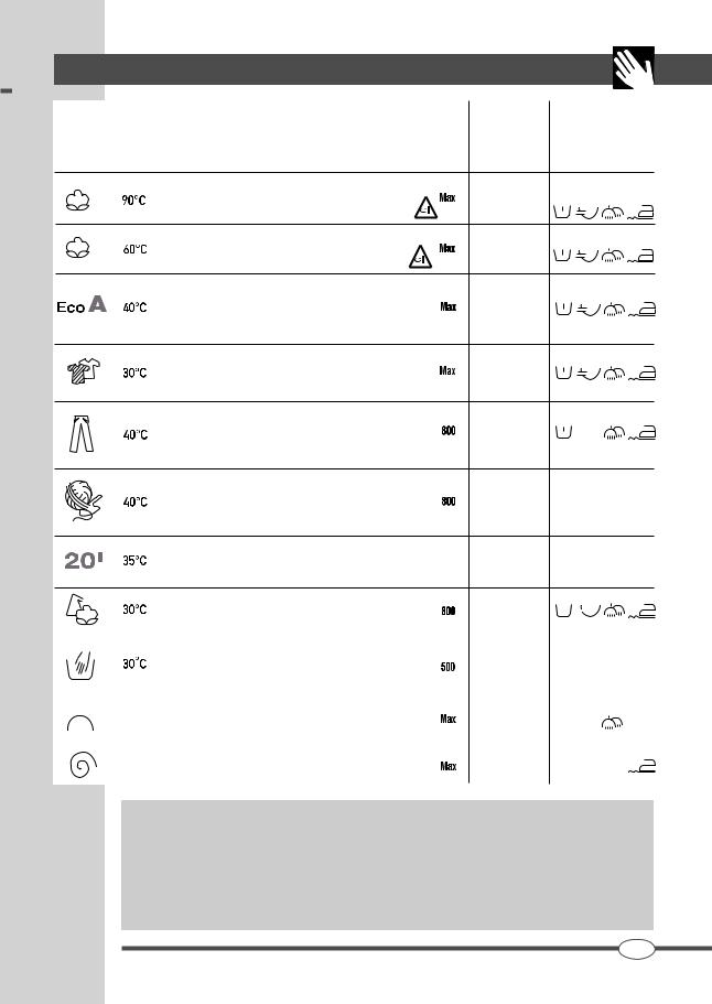
|
BEDIENFELD |
13 |
||||
|
Max. |
Maximale Ladung |
||||
|
Schleuim Verhältnis zum |
|||||
|
Programme |
Wäschetyp |
derdrehModell und dem |
Optionen |
||
|
zahl |
gewähltem |
||||
|
Symbol |
Temperatur |
(U/min) |
Programm |
||
|
Stark verschmutzte Weißwäsche aus Leinen und Baumwolle, auch |
6.0 |
||||
|
mit organischen Flecken. |
T |
||||
|
In diesem Programm kann kenn Bleichmittel verwendet werden. |
|||||
|
Strapazierfähige Weißund Buntwäsche aus Leinen und Baumwolle. |
|||||
|
In diesem Programm kann kenn Bleichmittel verwendet werden. |
6.0 |
T |
|||
|
Bezugsprogramm in Übereinstimmung mit der Norm EN60456. |
|||||
|
Das Sonderprogramm EcoA gewährleistet beste Ergebnisse in der |
|||||
|
Waschwirkungsklasse A bei nur 40°C, was maximale Energieeinsparung |
6.0 |
T |
|||
|
bietet. Bezugsprogramm für die Verbraucherverbände. |
|||||
|
Das Programm Coloured ermöglicht das gemeinsame Waschen von verschieden |
|||||
|
farbigen Wäschestücken; helle und dunkle Teile können unter voller Sicherheit |
6.0 |
T |
|||
|
zusammen gewaschen werden, ohne Verfärbungen zu riskieren. |
|||||
|
Das Spezialprogramm für Jeans ist ein Schongang bei |
40°C, der |
||||
|
Denimstoffe pfleglich behandelt, Verwaschen vermeidet und die |
3.0 |
||||
|
Farben erhält. Kleidungsstücke aus Denim Delavé bleiben immer |
|||||
|
wie neu. |
Das Wollprogramm ist ideal zum Waschen empfindlicher Kleidungsstücke mit dem Pflegeetikett «Maschinenwaschbar».
Es gewährleistet die schonende Behandlung der Farben und die lange 1.5 Wahrung der ursprünglichen Beschaffenheit der Kleidungsstücke.
Der Waschgang Express 20′ eignet sich zum schnellen Auffrischen
von leicht verschmutzter Wäsche in nur 20 Minuten. Express 20′  3.0 wäscht bei 35°C und hilft kostbare Zeit einzusparen.
|
Mit dem speziellen Programm Mix können Stoffe verschiedener Art (Baumwolle, |
3.0 |
T |
|||||||||
|
Synthetikgewebe, Mischgewebe) problemlos zusammen gewaschen werden. |
|||||||||||
|
Empfindliche Wäschestücke müssen besonders schonend behandelt |
|||||||||||
|
werden und werden normalerweise von Hand gewaschen. Die |
1.0 |
||||||||||
|
spezifische Handwäsche gewährleistet die schonende Behandlung |
|||||||||||
|
der Wäsche. |
|||||||||||
|
Das Spülprogramm ist nützlich zum Spülen von Handwäsche oder |
6.0 |
||||||||||
|
zum Auffrischen von längere Zeit nicht benutzten Wäschestücken. |
|||||||||||
|
Die Schleuderdrehzahl ist verstellbar und kann allen Gewebearten |
6.0 |
||||||||||
|
angepasst werden. |
Unwuchtkontrollsystem der Schleuderfüllung:
Diese Waschmaschine ist mit einem speziellen elektronischen Kontrollsystem ausgestattet, welches die Wäsche optimal in der Trommel verteilt. Dieses System sorgt vor jedem Schleudergang dafür, dass die Wäsche so gleichmäßig wie möglich in der Trommel verteilt wird. Falls die Wäsche unregelmäßig verteilt ist, wird die Geschwindigkeit des letzten Schleudergangs aus Sicherheitsgründen vermindert, und bei starker Unwucht ganz ausgelassen.
DE
SM2734
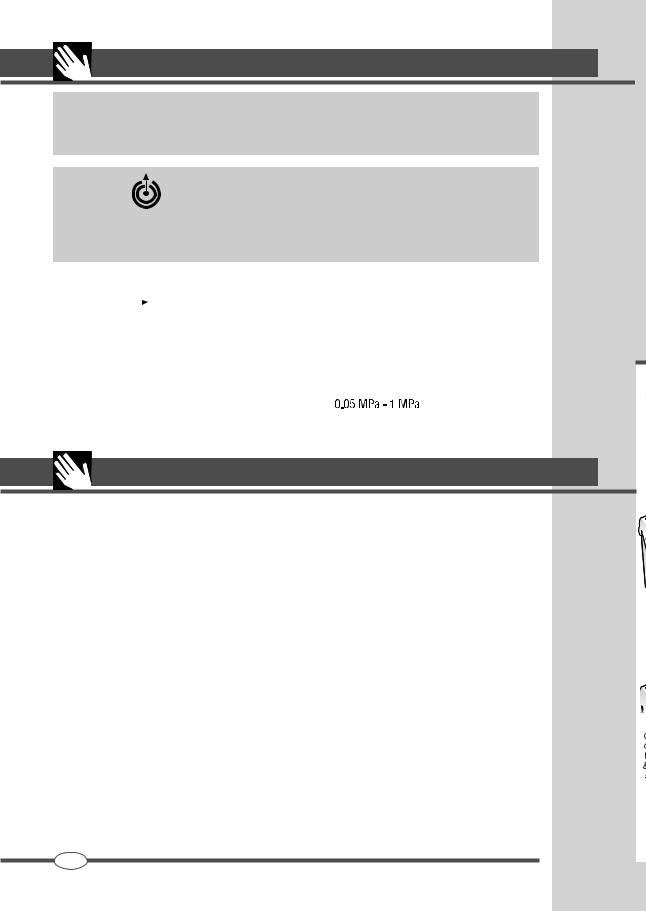
|
14 |
TECHNISCHE CHARAKTERISTIKEN |
EASY LOGIC: Das System EASY LOGIC passt die Waschdauer, sowie den Wasserund Stromverbrauch automatisch der jeweils in die Maschine eingefüllten Wäschemenge an. Die Funktion Halbe Füllung ist hier überflüssig, weil das System EASY LOGIC die Betriebsparameter automatisch einstellt.
SMART STOP : Die Funktion smart stop ermöglicht die korrekte Positionierung der Trommel am Ende des Waschgangs und erleichtert dadurch das Entnehmen der Wäsche.
Es ist dennoch möglich, dass die Positionierung bei bestimmten Bedingungen der Ladung ungenau ist und es daher notwendig ist, die Trommel teilweise zu drehen.
|
MODELL |
TLN126S |
TLN106S |
|||||||
|
W/B/A |
W/B/A |
||||||||
|
Breite (cm) |
40.0 |
40.0 |
|||||||
|
Abmessungen Höhe (cm) |
90.0 |
90.0 |
|||||||
|
Tiefe (cm) |
60.0 |
60.0 |
|||||||
|
Max. Schleuderdrehzahl (U/min) |
1200 |
1000 |
|||||||
|
Max. Füllung |
6.0 |
6.0 |
|||||||
|
Wasserdruck |
|||||||||
|
Elektroanschluss |
siehe Typenschild |
ANMERKUNGEN
………………………………………………………………………………………………………………………………………………………………………………………………………………………………………………………………..
………………………………………………………………………………………………………………………………………………………………………………………………………………………………………………………………..
………………………………………………………………………………………………………………………………………………………………………………………………………………………………………………………………..
………………………………………………………………………………………………………………………………………………………………………………………………………………………………………………………………..
………………………………………………………………………………………………………………………………………………………………………………………………………………………………………………………………..
………………………………………………………………………………………………………………………………………………………………………………………………………………………………………………………………..
………………………………………………………………………………………………………………………………………………………………………………………………………………………………………………………………..
………………………………………………………………………………………………………………………………………………………………………………………………………………………………………………………………..
………………………………………………………………………………………………………………………………………………………………………………………………………………………………………………………………..
………………………………………………………………………………………………………………………………………………………………………………………………………………………………………………………………..
………………………………………………………………………………………………………………………………………………………………………………………………………………………………………………………………..
………………………………………………………………………………………………………………………………………………………………………………………………………………………………………………………………..
………………………………………………………………………………………………………………………………………………………………………………………………………………………………………………………………..
………………………………………………………………………………………………………………………………………………………………………………………………………………………………………………………………..
DE
SM2734
 Loading…