
Output limiter
Proportional cycle
Manual control
Control output characteristic
Isolation
External control input (DI)
Number of input points
Type of input
Input rating
Input holding time
Isolation
Action input
Event output
Contact output rating
Action
Hysteresis
Types
Event setting range
Absolute value alarm : Within measuring range
Deviation alarm : Higher limit deviation –1999 — 2000 digits, lower limit deviation –1999 — 2000 digits
Outside higher/lower limit deviations: 0 — 2000 digits
Within higher/lower limit deviations : 0 — 2000 digits
Standby action
Output updating cycle
Isolation
Communication function (option)
Type of communication
Communication system
Synchronization system
Communication distance
Communication address
Communication speed
Communication delay
Communication memory mode
Communication protocol
Communication mode type
Number of connectable instruments : 1 for RS-232C, 31 for RS-485 (Address setting 1 — 255)
Isolation
Others
: Lower limit 0.0 — 99.9%, higher limit 0.1 — 100.0%
: 1 — 120 seconds (when contact and SSR drive voltage output)
: 0.0 — 100.0% Setting resolution 0.1
: RA/DA to be set by front key
: Contact output insulated from all
AO (analog output) not insulated from SSR drive voltage, current or voltage output but insulated
from others
: 4
: Edge or level input (none, RUN/RST, HLD, ADV, FIX and start pattern No.)
DI1 fixed to RUN/RST for DI2 — 4, selectable from none, RUN/RST, HLD, ADV, FIX and start
pattern No.
: Voltage 5V DC (0.5mA/1 input)
: Minimum 0.125 seconds
: Not insulated from input and system but insulated from others.
: No-voltage contact or open collector
: Normal open (1a x 3 common) 240V AC 1A (resistive load)
: ON-OFF action
: 1 — 999 digits (during alarm output)
: Selectable from the following 16 types respectively for EV1, EV2 and EV3
No selection, Higher limit deviation, Lower limit deviation, Outside higher/lower limit deviations,
Within higher/lower limit deviations, Higher limit absolute value, Lower limit absolute value,
Scaleover, Hold, Guarantee soak, Time signal (2 types), RUN status, step signal, End signal, FIX
: Selectable from the following 4 types respectively for EV1, EV2 and EV3
: None, Standby 1 (standby only when power is applied), Standby 2 (standby when power is applied,
when SV in execution is changed, or when switching RST to RUN) and Standby 3
(input abnormality not output [Control mode])
: 0.25 second
: Insulated from other inputs
: RS-232C or RS-485
: RS-232C/3-line type half duplex system, RS-485/2-line type half duplex multi-drop (bus) system
: Start-stop synchronization system
: RS-232C/Max. 15m, RS-485/Max. 500 m (depending on conditions)
: 1 – 255
: 1200, 2400, 4800, 9600, 19200 bps
: 1 — 100 (0.512msec/unit)
: Selectable from EEP, rAm and r_E
: Shimaden standard mode
Data format
: 7E1, 7E2, 7N1, 7N2, 8E1, 8E2, 8N1, 8N2
Control code
: STX_ETX_CR, STX_ETX_CRLF, @_:_CR
Checksum (BCC)
: Add, Add two’s cmp, XOR, None
Communication data : ASCII data
: MODBUS ASCII mode
Data format
: 7E1, 7E2, 7N1, 7N2
Control code
: CRLF
Checksum (BCC)
: LRC check
Communication data : ASCII data
Function code
: 03H, 06H
1)03H Reading of data
2)06H Writing of data
: MODBUS RTU mode
Data format
: 8E1, 8E2, 8N1, 8N2
Control code
: NON
Checksum (BCC)
: CRC-16
Communication data : Binary data
Function code
: 03H, 06H
1)03H Reading of data
2)06H Writing of data
: Selectable from COM1 and COM2.
: insulated from other inputs and outputs
: Start character and BCC operation method also selectable
— 34 —

FP93
Program Controller
Instruction Manual
Thank you for purchasing a Shimaden product. Please check that the delivered product is the correct item
you ordered. Please do not begin operating this product before you read this instruction manual thoroughly
and understand its contents.
"Notice"
Please ensure that this instruction manual is given to the final user of the instrument.
"Preface"
This instruction manual is meant for those who will be involved in the wiring, installation, operation and routine
maintenance of the FP93. It describes matters to be attended to in handling the FP93, how to install it, wiring, its
functions and operating procedure. Keep this manual at the work site while handling the instrument and follow the
guidance provided herein.
FP93F-1HE
Jan. 2018
-1-
Contents
1. Safety Rules ................................................................. 3
(3) Setting FIX No. ...............................................................17
(4) Setting FIX Event Action Point ........................................17
2. Introduction................................................................... 4
5-9. Explanation of screen Group 4 and Setting .......... 18
(1) Setting Outputs of PID Nos. 1 – 6 ...................................18
(2) Setting Zone PID ............................................................18
2-1. Check before Use .................................................. 4
2-2. Handling Instruction ............................................... 4
5-10. Explanation of Screen Group 5 and Setting........ 18
3. Installation and Wiring .................................................. 4
(1) Setting the Number of Patterns ......................................18
(2) Setting Time Unit ............................................................19
(3) Setting With/Without Power Failure Compensation ........19
(4) Setting Input Abnormality Mode ......................................19
(5) Setting Measuring Range Code ......................................19
(6) Setting Input Unit ............................................................19
(7) Setting Input Scaling .......................................................19
(8) Setting PV Bias ...............................................................19
(9) Setting PV Filter ..............................................................19
(10) Setting Output Control Characteristic ...........................19
(11) Setting Proportional Cycle.............................................19
(12) Setting SV Limiter .........................................................19
(13) Setting External Control Input .......................................20
(14) Setting Events ...............................................................20
(15) Setting Status Output (DO) ...........................................21
(17) Setting Communication .................................................21
(18) Setting Keylock .............................................................22
3-1. Installation Site (environmental conditions) ............ 4
3-2. Mounting ................................................................ 5
3-3. External Dimensions and Panel Cutout.................. 5
3-4. Wiring ..................................................................... 5
3-5. Terminal Layout ...................................................... 6
3-6. Terminal Arrangement Table ................................... 6
4. Names and Functions of Parts on Front Panel ............. 7
5. Explanation of Screens and Setting ............................. 9
5-1. Parameter Flow ...................................................... 9
(1) How to Move from Screen Group to Screen Group and
Explanation of Screen Groups ......................................... 9
5-2. Application of Power and Display of Initial Screen 13
5-3. How to Change Screens ...................................... 13
5-11. Measuring Range Codes Table ........................... 22
6 Operation and Functions .............................................. 23
6-1. Using FIX Mode .................................................... 23
6-2. Setting Target Value (SV) (FIX Mode) ................... 23
6-3. Setting Output Manually ....................................... 23
6.4. Auto Tuning (AT) ................................................... 23
6-5. PID Action............................................................. 24
6-6. Manual Reset ....................................................... 24
6-7. Output Lower Limit and Higher Limit Setting Limiters
............................................................................. 24
6-8. Proportional Cycle Time........................................ 24
6-9. Zone PID .............................................................. 25
6-10. External Control Input (DI) .................................. 25
6-11. Events ................................................................. 26
6-12. Setting Event Standby Action ............................. 26
6-13. Diagrams of Alarm Actions Selectable as Event . 26
6-14. Event and Status Output Actions ........................ 26
6-15. Time Signal ......................................................... 27
6-16. Status (DO) Output ............................................. 28
6-17. Auto Return Function .......................................... 28
6-18. Notes on RAM as Communication Memory Mode28
(1) How to Change Screen Groups 0 - 5 ............................. 13
(2) How to Change Screen in Screen Group 0 .................... 13
(3) How to Change Screen in Screen Group 3 .................... 14
(4) How to Change Set Values (Data) ................................. 14
5-4. Before Starting Up................................................ 14
(1) Checking Wiring ............................................................. 14
(2) Applying power ............................................................... 14
(3) Setting Measuring Range .............................................. 14
(4) Setting Control Mode ..................................................... 14
(5) Setting Control Output Characteristic ............................ 14
(6) Setting Other Data ......................................................... 14
(7) Note on Initialization upon Change of Data ................... 14
5-5. Explanation of Screen Group 0 and Setting ......... 15
(1) Setting HLD Execution ................................................... 15
(2) Setting ADV Execution ................................................... 15
(3) Setting Auto Tuning (AT) Execution ............................... 15
5-6. Explanation of Screen Group 1 and Setting ......... 15
(1) Setting Start SV ............................................................. 15
(2) Setting End Step ............................................................ 15
(3) Setting Time Signal ........................................................ 16
(4) Setting Event Action Point .............................................. 16
(5) Setting the Number of Program Executions ................... 16
(6) Setting PV Start ............................................................. 16
(7) Setting Guarantee Soak Zone ....................................... 17
5-7. Explanation of Screen Group 2 and Setting ......... 17
(1) Setting Step SV .............................................................. 17
(2) Setting Step Time ........................................................... 17
(3) Setting PID No. .............................................................. 17
5-8. Explanation of screen Group 3 and Setting .......... 17
7. Error Codes, Causes and Remedies .......................... 28
8. Record of Parameter Setting ...................................... 29
9. Specifications .............................................................. 33
(1) Setting ON/OFF of FIX Mode ......................................... 17
(2) Setting FIX SV Value...................................................... 17
-2-
1. Safety Rules
For matters regarding safety, potential damage to equipment and/or facilities, additional instructions and notes are indicated by the
following headings.
· WARNING
This heading indicates hazardous conditions that could cause injury or death of personnel unless extreme caution is exercised.
· CAUTION
This heading indicates hazardous conditions that could cause damage to equipment and/or facilities unless extreme caution is exercised.
Note
This heading indicates additional instructions and/or notes.
The mark 1 Ã represents a protective conductor terminal. Make sure to ground it properly.
· WARNING
The FP93 Program Controller are control instruments designed for industrial use to control temperature, humidity and other physical
values. Avoid using it for control of devices which may seriously affect the human life. When used, adequate and effective safety
measures must be taken. No warranty is valid in the case of an accident arising from the use of this product without such safety
measures.
· WARNING
z For using this instrument, house it in a control box or the like lest terminals should be in contact with a person.
z Don't draw out the instrument from the case. Don't let your hand or a conductive body in the case. It may lead to serious injury or
death due to an electric shock.
z Make sure to ground protective conductor terminals.
· CAUTION
z To avoid damage to connected equipment, facilities or products due to a fault of the product, safety measures must be taken before
usage, such as the installation of a fuse, an overheating protection device and the like. No warranty is valid in the case of an accident
arising from the use of this product without such safety measures.
· CAUTION
z The · mark on the plate affixed to the instrument:
On the terminal nameplate affixed to the case of this instrument, the alert mark · is printed. This is to warn you of the risk of
electric shock which may result if the charger is touched while being energized.
z As a means to turn the power off, a switch or a breaker should be installed in the external power circuit to be connected to the power
terminal of the instrument. Fix the switch or the breaker adjacently to the instrument in a position which allows it to be operated
with ease, with an indication that it is a means of turning the power off. Use a switch or a breaker which meets the requirement of
IEC60947.
z Fuse:
Since the instrument does not have a built-in fuse, do not forget to install a fuse in the power circuit to be connected to the power
terminal. A fuse should be positioned between a switch or a breaker and the instrument and mounted on the L side of the power
terminal.
Fuse rating / characteristics: 250V AC 1A / medium lagged or lagged type.
Use a fuse which meets the requirement of IEC60127.
z Voltage / current of a load to be connected to the output terminal and the alarm terminal should be within a rated range.
Otherwise, the temperature will rise to reduce the life of product and/or to result in problems with the product. For rated
voltage/current, see "9. Specifications" of this manual.
The output terminal should be connected with a device which meets the requirements of IEC61010.
z A voltage / current different from that of the input specification should not be applied to the input terminal.
It may reduce the life of the product and/or result in problems with the product. For rated voltage / current, see "9. Specifications" of
this manual.
z In the case of voltage or current input, the input terminal should be connected to a device which meets the requirement of
IEC61010.
The instrument is provided with a draft hole for heat discharge. Take care to prevent metal and other foreign matters from getting
into it. Failure to do so may result in trouble with the instrument or may even cause a fire.
z Don't block the draft hole or allow dust or the like to stick to it. A rise in temperature or insulation failure may result in a reduction
of the life of the product and/or problems with it or may cause a fire.
For spaces between installed instruments, refer to "3-3. External Dimensions and Panel Cutout."
z It should be noted that repeated tolerance tests against voltage, noise, surge, etc. may lead to deterioration of the instrument.
z Users are prohibited from remodeling the product or abnormal use of it.
z It takes 30 minutes to display the correct temperature after applying power to the Program Controller. (Therefore, turn the power on
more than 30 minutes prior to the operation.)
-3-
2. Introduction
2-1. Check before Use
This product has been fully inspected for quality assurance prior to shipment. Nevertheless, you are requested to make sure that there is no
error, damage or shortage of delivered items by checking the model codes and the external view of the product and the number of
accessories.
c Confirmation of Model Codes
Check the model codes stuck to the case of the product to ascertain if the respective codes designate what were specified when you ordered
it, referring to the following code table:
Example of model codes:
FP93 - 8 Y 90
-1 3 5 0
1. Name of produuct FP93
2. Input
8 : Multi-input: thermocouple, R.T.D., voltage (mV), Voltage (V)
4 : Current (mA)(attached with an extermal resistor 250 ȍ)
9 : With remarks
3. Control output Y : Contact
I : Current
P : SSR drive voltage
V
4. Power supply 90
08
5. Status output 0
(Do)
1
6.Analog output 0
(AO)
3
4
6
7.Communication 0
5
7
8. Remarks
0
9
d Accessories
: Voltage X: With remarks
: 100-240V AC
: 24V AC/DC
: Without
: With 9: With special note
: Without
: 0-10mA
: 4-20mA
: 0-10V 9: With remarks
: Without
:RS-485
:RS-232C 9: With remarks
: Without
: With
This instruction manual
The Communication interface instruction manual
(in case optional communication function is added)
Unit seals
External resistor 250 ȍ (for current input)
Terminal resistor 120 ȍ (for RS-485)
1 copy
1 copy
1 sheet
1 pc.
1 pc.
NOTE: For any problem with the product, shortage of accessories or request for information, please contact our sales agent.
2-2. Handling Instruction
c Don't operate the keys on the front panel with a hard or sharply pointed object. Operate the keys only by softly touching
them by your fingertips.
d When cleaning the instrument, wipe it gently with a dry cloth. Never use solvent such as a thinner.
3. Installation and Wiring
3-1. Installation Site (environmental conditions)
· CAUTION
This instrument should not be used in any of the places mentioned below. Selection of these places may result in trouble with the
instrument, damage to it or even a fire.
c Where flammable gas, corrosive gas, oil mist and particles that can deteriorate electrical insulation are generated or abundant.
d Where the temperature is below -10 ˚C (14 ˚F) or above 50 ˚C (122 ˚F).
e Where the relative humidity is above 90%RH or below dew point.
f Where highly intense vibration or impact is generated or transferred.
g Near high voltage power lines or where inductive interference can affect the operation of the instrument.
h Where the instrument is exposed to dew drops or direct sunlight.
i Where the height is above 2000 m.
j Outdoors.
k Where the instrument is exposed to the flow of blowing air.
NOTE: The environmental conditions belong to the installation category II of IEC60664 and the degree of pollution is 2.
-4-
3-2. Mounting
· CAUTION
For safety's sake and to protect the functionality of the product, don't draw out its body from the case. If it needs to be drawn out for
replacement or repair, contact our sales agent.
c Cut a hole for mounting the controller in the panel by referring to the cutout drawing in Section 3-3.
d The panel thickness should be 1.0 - 4.0 mm.
e As the instrument is provided with pawls for fixing, just press it firmly from the front of the panel. The case is fixed to the panel by
means of the pawls.
f The FP93 is designed as a panel-mounting model. Never use it without mounting on the panel.
3-3. External Dimensions and Panel Cutout
External dimensions
Panel cutout drawing
Unit: mm
3-4. Wiring
In wiring operation, close attention should be paid to the following:
· CAUTION
z Make sure to disconnect this instrument from any power source during wiring operation to prevent an electric shock.
z Be certain that the protective conductor terminal ( Ã ) is properly grounded. Otherwise, an electric shock may result.
z To prevent an electric shock, don't touch wired terminals and other charged elements while they are being energized.
c In wiring operation, follow the terminal layout shown in Section 3-5 and the terminal arrangement in Section 3-6 and make sure to carry
out the correct wiring.
d Use press-fit terminal which fits an M3.5 screw and has a width of 7 mm or less.
e In case of thermocouple input, use a compensating cable compatible with the selected type of thermocouple.
f In the case of R.T.D. input, the resistance of a single lead wire must be 5 or less and the three wires must have the same resistance.
g The input signal wire must not be accommodated with a high-voltage power cable in the same conduit or duct.
h Shield wiring (single point grounding) is effective against static induction noise.
i Twisting the input wires at short and equal intervals is effective against electromagnetic induction noise.
j In wiring for power supply, use a wire or cable whose performance is equal to or higher than the 600V vinyl insulated wire having a
sectional area of 1 mm2 or larger.
2
k The wire for grounding must have a sectional area of 2 mm or larger and must be grounded at a grounding resistance of 100 or less.
l Clamp the screws of terminals firmly. Clamping torque: 1.0 N • m (10kgf • cm)
ջ If the instrument appears to be easily affected by power supply noise, use a noise filter to prevent malfunctioning.
ռ Mount the noise filter on the grounded panel and make wire connection between the noise filter output and the power line terminals of
the controller as short as possible.
-5-
3-5. Terminal Layout
(Follow the terminal layout and terminal arrangement table shown below in your wiring operation.)
3-6. Terminal Arrangement Table
Name of terminal
Description / Code
Power supply
100 - 240V AC/24V AC: L, 24V DC: +
100 - 240V AC/24V AC: N, 24V DC: Protective conductor
Protective grounding Ã
Input
Voltage (V) Current (mA): +
R.T.D.: A, thermocouple/Voltage (mV): +
R.T.D.: B, thermocouple/Voltage (mV, V), Current (mA): –
R.T.D.: B
Control output
Contact: COM, SSR drive voltage/Voltage/Current: +
Contact: NO, SSR drive voltage/Voltage/Current: –
Contact: NC
Event output
COM
EV1
EV2
EV3
Analog output
+
(option)
Communication
SG
(option)
RS-232C: SD, RS-485: +
RS-232C: RD, RS-485: –
External control input
COM
DI1
DI2
DI3
DI4
Status output (DO)
COM
(option)
DO1
DO2
DO3
DO4
Terminal No.
11
12
13
6
7
9
10
14
15
16
17
18
19
20
21
22
23
24
25
1
2
3
4
5
26
27
28
29
30
NOTE 1: With thermocouple, voltage, or current input, shorting across B and B terminal will cause an error. Leave terminal No.10 open.
NOTE 2: With voltage (V) or current (mA) input, don't connect anything with terminal No.7. Any connection with it may cause problems
with the instrument.
-6-
4. Names and Functions of Parts on Front Panel
Name
Function
c Measured value (PV)
display
(1) Present measured value is displayed in the screen group 0. (red)
(2) Type of parameter is shown on each parameter screen.
d Action display
(1)
(green) Ascending action lamp
• Lights while ascending step is in execution.
(2)
(green) Level action lamp
• Lights while level step is in execution.
(3)
(green) Descending action lamp
• Lights while descending step is in execution.
(4) OUT (green) Control output lamp
• Lights when contact or SSR drive voltage output is ON, goes out when output turns OFF.
• For current or voltage output, brightness increases or decreases in proportion to output.
(5 ) RUN (green) RUN action lamp
• Lights while program is in execution.
• Blinks while FIX is in execution.
(6) HLD (green) HLD action lamp
• Lights when a brief suspension (Hold) is set while program is in execution.
(7) GUA (green) GUA action lamp
• Lights in case PV value does not reach a set range of deviation values when moving to level step
during program execution (guarantee soak).
(8) COM (green) Communication action lamp
• Lights when COM mode is selected in case the instrument includes the communication option. The
lamp does not light if local is selected as communication mode.
(9) AT (green) Auto tuning action lamp
• Blinks while AT is in execution. The lamp lights during standby for AT and goes out when AT action
comes to an end or is terminated.
(10) MAN (green) Manual control output action lamp
• Blinks when manual control output is selected on output screen. The lamp remains extinct during
automatic control output.
(11) EV1 (orange) Event 1 output action lamp. Lights when event 1 turns ON.
EV2 (orange) Event 2 output action lamp. Lights when event 2 turns ON.
EV3 (orange) Event 3 output action lamp. Lights when event 3 turns ON.
(12) DO1 (green) Status output 1 action lamp. Lights when status output 1 turns ON.
DO2 (green) Status output 2 action lamp. Lights when status output 2 turns ON.
DO3 (green) Status output 3 action lamp. Lights when status output 3 turns ON.
DO4 (green) Status output 4 action lamp. Lights when status output 4 turns ON.
e Pattern number display
(1) Pattern No. currently selected is displayed. (green)
f Step No. Display
(1) Step No. currently in execution is displayed. (green)
(2) Step No. currently set in screen group 2 is displayed.
(3) PID No. currently set in screen group 4 is displayed.
g Target set value (SV)
display
(1) Target set value is displayed on the basic screen of screen group 0. (green)
(2) Present output value is displayed in % on the output monitor screen of screen group 0.
(3) Selected item and set value are displayed on each parameter screen.
-7-
Name
h Operating keys
Function
(1)
(parameter) key
• Pressing this key on any screen calls the next screen onto display.
• Pressing this key continuously for 3 seconds calls the initial screen of screen group 5.
(2)
(up) key
• Used to increase a numerical value on a numerical value setting screen.
• Used to select an item on an item selection screen.
(3)
(down) key
• Used to decrease a numerical value on a numerical value setting screen.
• Used to select an item on an item selection screen.
(4)
(entry) key
• Used to register a set data changed by means of the
or
key on each screen (the decimal
point of the rightmost digit goes out).
• When pressed for 3 seconds continuously on output (OUT) screen, this key switches between
automatic output and manual output.
(5)
(group) key
• When pressed in the middle of setting in screen groups 1, 3, 4 or 5, the initial screen of the group is
called onto display.
• When pressed in the screen group 2, the initial screen of screen group 1 is called onto display.
• When pressed on the basic screen, the display moves to screen group 1, screen group 3, screen
group 4 and the basic screen in the order mentioned.
• When pressed on the initial screen of screen group 5, the basic screen is called.
(6)
(pattern) key
• When pressed during stop (RST) on the basic screen, a starting pattern can be selected. It is
registered by pressing the
key
• This key is used to move to other screen groups. For details, see Section 5-1 or 5-5.
(7)
(step) key
• This key is used to move to other screen groups. For details, see Section 5-1 or 5-5.
(8)
(run/reset) key
• When pressed continuously for 3 seconds on the basic screen, execution (RUN) and stop (RST) are
switched.
• When pressed in any of screen groups 1 - 5, the preceding screen is returned onto display.
-8-
5. Explanation of Screens and Setting
5-1. Parameter Flow
NOTE: Four kinds of frame lines signify the following. The figure on the left of each frame represents screen No.
Screens regularly shown by key
operation and other means.
Screens shown when appropriate option is added or
selected.
Screens may or may not be shown
depending upon setting.
Screens for monitoring (without automatic return).
(1) How to Move from Screen Group to Screen Group and Explanation of Screen Groups
NOTE 1: To move among screen groups 0, 1, 3 and 4, press the
group 1, 3 or 4.
NOTE 2: To move between screen groups 0 and 5, pressing the
the initial screen of screen group 5, and pressing the
group 0.
NOTE 3: Pressing the
screen.
key on the basic screen of screen group 0 or the initial screens of screen
key for 3 seconds continuously on the basic screen of screen group 0 calls
key on the initial screen of screen group 5 calls the basic screen of screen
key in any screen group calls the next screen and pressing it on the last screen of a screen group calls the initial
NOTE 4: A key shown above and outside a chain line frame (
) surrounding each screen group means that you can move from any
of the screen within the frame to a designated screen by pressing that key. (This applies to screen groups 1, 2, 3, 4 and 5.)
Example: ĺ Screen Group
NOTE 5: The screen group 1 has patterns 1 - 4. (One pattern has 16 setting screens.) The number of patterns is selectable (which is set on the
5-1 screen; the initial value is 4).
NOTE 6: The screen group 2 has steps 1 to 40 (one step containing three setting screens). The number of steps is selectable (which is set on the
1-2 screen; the initial value is 10).
NOTE 7: The screen group 4 has 6 PID Nos. (Each having 8 setting screens) and Zone PID.
NOTE 8: Within a screen group, you can move from screen to screen by pressing an appropriate key indicated in screen sequences (which are
shown in the following page on).
-9-
- 10 -
- 11 -
Screen Group 5
Initial screen
5-0
5-1
5-2
5-3
5-4
5-5
5-6
5-7
5-8
5-9
5-10
5-11
5-12
5-13
5-14
5-15
5-16
5-17
5-18
5-19
Initial setting screen group Screen
The number of patterns setting
Time unit setting
5-23
Event 2 hysteresis setting
5-24
Event 2 standby action setting
With/without power failure compensation setting
5-25
Event 3 type setting
Input abnormality mode setting
5-26
Event 3 hysteresis setting
Measuring range code setting
5-27
Event 3 standby action setting
Input unit setting
5-28
Status output 1 action code setting
5-29
Status output 2 action code setting
5-30
Status output 3 action code setting
5-31
Status output 4 action code setting
5-32
Analog output type setting
5-33
Analog output scaling lower limit setting
5-34
Analog output scaling higher limit setting
Input scaling lower limit value setting
Input scaling higher limit value setting
Input scaling decimal point position setting
PV Bias setting
PV filter setting
5-23 screen
Output control characteristics setting
Proportional cycle setting
SV limiter lower limit value setting
SV limiter higher limit value setting
External control input 2 action code setting
External control input 3 action code setting
External control input 4 action code setting
Event 1 type setting
Event 1 hysteresis setting
5-20
Event 1 standby action setting
5-21
Event 2 type setting
5-22
5-23 screen
5-35
5-36
5-37
5-38
Communication mode setting
Communication protocol Setting
Communication address setting
Communication speed setting
5-41
Communication data format setting
Start character setting
BCC operation type setting
5-42
Delay time setting
5-43
Communication memory mode setting
5-44
Communication mode type setting
- 12 -
5-39
5-40
5-45
Keylock setting
5-23 screen
5-2. Application of Power and Display of Initial Screen
When power is applied, the initial screen and two screens are displayed successively, each for about 1 second as shown below. Then the
basic screen is displayed.
5-3. How to Change Screens
(1) How to Change Screen Groups 0 - 5
• Pressing the
key on the basic screen of screen group 0 calls the initial screen of screen group 1.
• Pressing the
key on the basic screen of screen group 0 continuously for 3 seconds calls the initial screen of screen group 5.
• Pressing the
key on any screen of screen group 1 calls the 2-1 screen of screen group 2.
• Pressing the
key on the initial screen of screen group 1 calls the initial screen of screen group 3.
• Pressing the
key on any of the screens of screen group 2 calls the initial screen of screen group 1.
• Pressing the
key on the initial screen of screen group 3 calls the initial screen of screen group 4.
• Pressing the
key on the initial screen of screen group 4 calls the basic screen of screen group 0.
• Pressing the
key on the initial screen of screen group 5 calls the basic screen of screen group 0.
• Pressing the
key on any screen midway of screen group 0, 1, 3, 4 or 5 calls the initial screen of the screen group.
• Pressing the
key on any screen midway of screen group 1, 2, 3, 4 or 5 calls the preceding screen.
(Nevertheless, to return to the initial screen in screen group 1 or 4, you have to press the
key or press the
key continuously to
move to the last screen of the group before returning to the initial screen.
c How to move among 0 - 4 screen groups
0-0 Basic screen 1-0 Program setting initial screen 3-0 FIX setting screen
jwh
key
key
i
~
i
rh
i
~
4-0 PID setting screen group
key
~
key
d How to move between screen group 0 and screen group 5
0-0 Basic screen
key
continuously
for
3
seconds
jwh
i i
rh
5-0 initial setting initial screen
~
key
(2) How to Change Screen in Screen Group 0
Every time the
key is pressed, the next screen is called, and the basic screen is called from the last screen.
0-0 Basic screen 0-1 Output monitoring screen
jwh
iq{q
©mrh
i i
rh
- 13 -
0-7 AT execution screen
|
i An omission
i
(3) How to Change Screen in Screen Group 3
Every time the
key is pressed, the next screen is called, and the basic screen is called from the last screen. Pressing the
calls the preceding screen.
(4) How to Change Set Values (Data)
To change data on a screen which is called by pressing the
key.
key, use the
or
key
key, and register the changed data by pressing the
5-4. Before Starting Up
To begin with, check the wiring and carry out the following on the respective setting screens. (Factory-set items and items already set
by equipment manufacturers need not be set here.)
(1) Checking Wiring
: Check that the wiring to connected terminals is carried out properly. If the power line is erroneously
connected to other terminals, it may cause burnout.
(2) Applying power
: Apply operating power. The controller is energized and the data display and other lamps light.
(3) Setting Measuring Range
: Select a code from the list of measuring range codes on the 5-5 Measuring range code setting screen. For
current, voltage or mV input, lower/higher limit values and the position of decimal point of the contents of
display in response to input signal should be set.
(Depending on a selected code, selection on the 5-6, 5-7 and 5-8 is also required.)
(4) Setting Control Mode
: In the case of ON-OFF (two-position) action, call the 4-1 Output proportional band setting screen of screen
group 4 and select OFF for P and register it.
(5) Setting Control Output Characteristic
: On the 5-12 Control output characteristics setting screen, select either RA (heating action) or DA (cooling
action) for Act according to the purpose of use and register it.
(6) Setting Other Data
: Input necessary items such as program, event action and external input of program control. Record necessary
data in "8. Record of Parameter Setting" and input them.
(7) Note on Initialization upon Change of Data
: When a set data on measuring range code, input unit, higher/lower limit value of input scaling, event type,
analog output type or the like is changed, related data is initialized and resetting is required.
- 14 -
e
f
c
d
c Measured value display (PV display)
d Target set value display (SV display)
e Pattern No. display (PTN display)
f Step No. display (STP display)
5-5. Explanation of Screen Group 0 and Setting
0-0 Basic screen
i
jwh
rh
3 seconds To 5-0 screen
To 1-0 screen
Initial value of SV: 0.0 or 0
Setting range: Within measuring range
PV display : Display of measured value (PV)
SV display : Display of target set value (SV) and change of setting
(in FIX mode)
PTN display : Display of pattern No. currently in execution.
STP display : Display of step No. currently in execution.
When the
key is pressed in the state of stop (RST), thedecimal
point of PTN display blinks to enable you to select a start pattern.
Upon selection, press the
key to register. In the event you do
not register in 3 minutes, the preceding state returns. When (FIX)
mode has been selected, FIX SV value can be changed by means of
the
or
key. When the
key is pressed for 3 seconds
on this screen, RUN is put into execution.
0-1 Output monitoring screen
jwh
i i ©mrh
To 0-0 screen
Manual output setting range: 0.0 ~ 100.0%
Control output value of Output is displayed on the SV display.
In automatic operation, the present output value is monitored. In
manual operation, a set output value is changed.
۔How to switch manual to/from auto
Press the
key for 3 seconds continuously while RUN is in
execution.
For further details, see 6-3 Setting Output Manually.
0-2 Step remaining time monitoring screen
i i
jwh
q{m{
To 0-0 screen
The SV display shows remaining time of the step currently in
execution. This is on display only during RUN execution in the
PROG mode. If stop (RST) is input through external control input
(DI) 1 or in the case of a change to FIX mode through DI, the 0-0
basic screen is returned.
(2) Setting ADV Execution
0-6 ADV execution setting screen
i i
|
i i
jwh
qqq{
(3) Setting Auto Tuning (AT) Execution
0-7 AT execution setting screen
i i
|
Initial value: OFF
Setting range: ON/OFF
The selection of ON puts AT in execution and AT is released when
OFF is selected. AT execution is possible only when RUN is in
execution and the AT lamp blinks during AT execution. The lamp
lights during standby.
While AT is in execution, setting and changing are not possible
except releasing AT execution, keylock setting, communication
mode switching, and RUN/RST, HLD and ADV setting on the
basic screen.
For further details, refer to "6-4. Auto Tuning (AT)."
To 0-0 basic screen
5-6. Explanation of Screen Group 1 and Setting
1-0 Initial screen (pattern 1)
To 1-0 (pattern 2) screen
To 2-1 (step 1) screen
i
To 3-0 screen
On PTN display, the number (1 ~ 4; decimal point blinking) of a
pattern intended to be set is shown.
~
(1) Setting
0-4 PID No. monitoring screen
i i
jwh
¦¦i
1-1 (pattern 2) screen
To 2-1 (step 1) screen
To 1-0 (pattern 1) screen
Initial value: 0
Setting range: Within limiter
Temperature at which program is started is set. A change in SV
limiter makes the four decimal place blinking.
(2) Setting End Step
1-2 End step setting screen
(1) Setting HLD Execution
0-5 HLD execution setting screen
¦
h
s
To 0-0 screen
The number of PID currently in use is shown on SV display. This
screen is on display only when RUN is in execution. If stop (RST) is
input through external control input (DI) 1, the 0-0 basic screen is
returned.
i i
Start SV
1-1 Start SV setting screen
To 0-0 screen
The present number of executions is shown on the SV display.
This is on display only when RUN is in execution in the PROG mode.
If stop (RST) is input through external control input (DI) 1 or in the
case of a change to FIX mode through DI, the 0-0 basic screen is
returned.
To 1-0 screen
Initial value : OFF
Setting range : ON/OFF
The selection of ON puts ADV in execution. Upon execution of
ADV, the step currently in execution is terminated and forced to
move to the next step.
This screen is displayed only when RUN is in execution in the
PROG mode. If stop (RST) is input through external control input
(DI) 1 or in the case of a change to FIX mode through DI, the 0-0
basic screen is returned.
In case | is set for external control input (DI), it functions
only as an input status monitoring screen. ADV is not valid for 1
second upon changing to a new step and for 2 seconds upon
execution of ADV.
0-3 Monitoring screen for the number of pattern executions
To 0-0 screen
Initial value: OFF
Setting range: ON/OFF
HLD is put in execution when ON is selected and selection of OFF
releases it. Upon execution of HLD, PROG execution is stopped
temporarily. The HLD lamp lights during the execution of HLD. This
screen is on display only when RUN is in execution in the PROG
mode. If stop (RST) is input through external control input (DI) 1 or
in the case of a change to FIX mode through DI, the 0-0 basic screen
is returned.
In case is set for external control input (DI), it functions only
as an input status monitoring screen. ADV input is not valid during
the execution of HLD.
s
~
ih
To 1-1 (pattern 2) screen
To 2-1 (step 1) screen
To 1-0 (pattern 1) screen
Initial value: 10
Setting range: 1 ~ Maximum number of steps
The number of steps of a program pattern is set. The number of
patterns is set on the 5-1 screen (initial value: 4). The maximum
number of steps changes according to the number of patterns.
The number of pattern = 1: The maximum number of steps = 40
The number of pattern = 2: The maximum number of steps = 20
The number of pattern = 4: The maximum number of steps = 10
In case a lower number than the number of step currently in
execution is set, the program terminates upon completion of the step
currently being executed or moves to the initial step
To 1-3 screen
To 0-6 screen
- 15 -
(3) Setting Time Signal
1-10 Time signal 2 (TS2) OFF time setting screen
j To 1-1 (pattern 2) screen s hrhh To 2-1 (step 1) screen To 1-0 (pattern 1) screen
Initial value: 00.00
Setting range: 00.00 ~ 99.59
A time from the start of step in which TS2 signal is stopped to
the stop of the signal is set. This screen is not displayed when
TS2 OFF step is OFF. For details about time signal, refer to
"6-15. Time Signal."
1-3 Time signal 1 (TS1) ON step setting screen
To 1-1 (pattern 2) screen
To 2-1 (step 1) screen
s
To 1-0 (pattern 1) screen
Initial value: OFF
Setting range: OFF, 1 ~ End step
A step in which TS1 signal is output is set. This screen is on
display when i (tmS1) is set for event or status output.
For details about time signal, refer to "6-15 Time Signal." A
change of end step makes four decimal places blink if set value
of end step < TS1 ON step setting.
1-4 Time signal 1 (TS1) ON time setting screen
To 1-1 (pattern 2) screen s hrhh To 2-1 (step 1) screen
To 1-0 (pattern 1) screen
(4) Setting Event Action Point
1-11 Event 1 (EV1) action point setting screen
~i To 1-1 (pattern 2) screen
s jhhh To 2-1 (step 1) screen
To 1-0 (pattern 1) screen
Initial value: Higher limit deviation value (Hd) 2000
Lower limit deviation value (Ld) –1999
Outside higher/lower limit deviation values
(od) 2000
Within higher/lower limit deviation values
(id) 2000
Higher limit absolute value (HA) Higher
limit value of measuring range
Lower limit absolute value (LA) Lower
limit value of measuring range
Setting range: Higher limit deviation value or lower limit
deviation value 1999 ~ 2000 digits
Within or outside higher/lower limit
deviations 0 ~ 2000 digits
Higher limit absolute value or lower limit
absolute value Within measuring range
This screen is displayed when action code Hd ~ LA is set for
EV1, and action point of set event in PROG mode is set. When
any other code than Hd ~ LA is set, the screen is not displayed.
1-12 Event 2 (EV2) action point setting screen
~j To 1-1 (pattern 2) screen
s qqq To 2-1 (step 1) screen
To 1-0 (pattern 1) screen
Initial value: 00.00
Setting range: 00.00 ~ 99.59
A time from the start of step in which TS1 signal is output to the
output of the signal is set.
This screen is not displayed when TS1 ON step is OFF.
1-5 Time signal 1 (TS1) OFF step setting screen
To 1-1 (pattern 2) screen
i s To 2-1 (step 1) screen
To 1-0 (pattern 1) screen
Initial value: OFF
Setting range: OFF, 1 ~ End step
A step in which TS1 signal is stopped is set. This screen is not
displayed when TS1 ON step is OFF. A change of end step
makes four decimal places blink if set value of end step < TS1
OFF step setting.
1-6 Time signal 1 (TS1) OFF time setting screen i To 1-1 (pattern 2) screen
s hrhh To 2-1 (step 1) screen
To 1-0 (pattern 1) screen
Initial value: 00.00
Setting range: 00.00 ~ 99.59
A time from the start of step in which TS1 signal is stopped to
the stop of the signal is set.
This screen is not displayed when TS1 ON step is OFF.
The same as the 1-11 screen except EV1 changed to EV2.
1-7 Time signal 2 (TS2) ON step setting screen
To 1-1 (pattern 2) screen
j s To 2-1 (step 1) screen
To 1-0 (pattern 1) screen
Initial value: OFF
Setting range: OFF, 1 ~ End step
1-13 Event 3 (EV3) action point setting screen
~k To 1-1 (pattern 2) screen
s jhhh To 2-1 (step 1) screen
To 1-0 (pattern 1) screen
The same as the 1-11 screen except EV1 changed to EV3.
A step in which TS2 signal is output is set. This screen is on
display when j (tmS2) is set for event or status output.
For details about time signal, refer to "6-15 Time Signal." A
change of end step makes four decimal places blink if set value
of end step < TS2 ON step setting. (5) Setting the Number of Program Executions
1-14 The number of program executions setting screen
s
1-8 Time signal 2 (TS2) ON time setting screen
To 1-1 (pattern 2) screen
j s hrhh To 2-1 (step 1) screen
To 1-0 (pattern 1) screen
To 1-1 (pattern 2) screen
i To 2-1 (step 1) screen
To 1-0 (pattern 1) screen
Initial value: 1
Setting range: 1 ~ 9999
The number of executions of a presently set pattern is set. In case
a lower number than the number of pattern currently being
executed is set, the program is terminated upon execution to the
end step.
Initial value: 00.00
Setting range: 00.00 ~ 99.59
A time from the start of step in which TS2 signal is output to the
output of the signal is set.
This screen is not displayed when TS2 ON step is OFF.
(6) Setting PV Start
1-9 Time signal 2 (TS2) OFF step setting screen
j To 1-1 (pattern 2) screen s To 2-1 (step 1) screen To 1-0 (pattern 1) screen
1-15 PV start setting screen
s
Initial value: OFF
Setting range: OFF, 1 ~ End step
A step in which TS2 signal is stopped is set. This screen is not
displayed when TS2 ON step is OFF. A change of end step
makes four decimal places blink if set value of end step < TS1
ON step setting.
¦ To 1-1 (pattern 2) screen
To 2-1 (step 1) screen
To 1-0 (pattern 1) screen
Initial value: OFF
Setting range: ON/OFF
Wasteful time is eliminated in case PV value is closer to the
setting point of step 1 than start SV.
To 1-10 screen
To 1-16 screen
- 16 -
(7) Setting Guarantee Soak Zone
5-8. Explanation of screen Group 3 and Setting
1-16 Guarantee soak zone setting screen
To 1-1 (pattern 2) screen
| s To 2-1 (step 1) screen
To 1-0 (pattern 1) screen
Initial value: OFF
Setting range: OFF, 1 ~ 999 digits
3-0 Initial screen
~
In case a deviation of step SV of level step from PV remains
outside a guarantee soak zone when a ramp step is changed to a
level step in the PROG mode, the step does not move to the next
but waits until it reaches the zone. A value is set as deviation of
the level step from SV. The GUA lamp lights during guarantee
soak.
To 4-0 screen
representing FIX mode is shown on PTN display.
(1) Setting ON/OFF of FIX Mode
3-1 FIX mode ON/OFF setting screen
To 3-0 screen
Initial value: OFF
Setting range: OFF/ON
ON/OFF of FIX mode is set. When FIX is selected in setting
external control input (DI), this screen is for monitoring
only.
To 1-0 Initial screen (pattern 1)
5-7. Explanation of Screen Group 2 and Setting
(1) Setting Step SV
(2) Setting FIX SV Value
3-2 FIX SV value setting screen
2-1 Step SV setting screen
To 2-1 (step 1) screen
i s h ¦ h
Initial value: 0.0
Setting range: Within limiter
SV value in FIX mode is set.
To 1-0 (pattern 1) screen
To 1-1 (pattern 2) screen
Initial value: 0.0
Setting range: Within limiter
The number of step being set now is shown on STP display
(decimal point blinks), and the number (1 ~ 4) of pattern to
which the step presently being set belongs is shown on PTN
display. On SV display, SV of the step is set. A change of SV
limiter makes four decimal places blink if a set SV value of the
step is outside the SV limiter.
(3) Setting FIX No.
3-3 FIX No. setting screen
h
(2) Setting Step Time
2-2 Step time setting screen
s
To 2-1 (step 1) screen
hrhi To 1-0 (pattern 1) screen
To 1-1 (pattern 2) screen
Initial value: 00.01
Setting range: 00.00 ~ 99.59
The length of time in which the step is executed is set.
(4) Setting FIX Event Action Point
3-4 FIX event 1 (EV1) action point setting screen
~i jhhh
(3) Setting PID No.
2-3 PID No. setting screen
i
s
To 3-0 screen
Initial value: 0
Setting range: 0 ~ 6
A PID No. in FIX mode is selected. This screen is not displayed
during the use of zone PID. When 0 is selected, action is carried
out as PID No.1.
i
To 3-0 screen
To 2-1 (step 1) screen
h To 1-0 (pattern 1) screen
To 1-1 (pattern 2) screen
Initial value: 0
Setting range: 0 ~ 6
The number of PID used in this step is set. The screen is not
displayed when zone PID is effective. Although any between 0
and 6 is selectable, setting 0 means that the PID No. remains
unchanged from that of the preceding step.
Whenever 0 is selected, action is carried out as PID No.1.
To 2-1 screen
To 3-0 screen
EV1 action point in FIX mode is set.
Initial value:
Higher limit deviation value (Hd) 2000
Lower limit deviation value (Ld) –1999
Outside higher/lower limit deviation values (od) 2000
Within higher/lower limit deviation values (id) 2000
Higher limit absolute value (HA) Higher limit value of
measuring range
Lower limit absolute value (LA) Lower limit value of
measuring range
Setting range:
Higher limit deviation value or lower limit deviation
value 1999 ~ 2000 digits
Within or outside of higher/lower limit deviations
0 ~ 2000 digits
Higher limit absolute value or lower limit absolute value
Within measuring range
This screen is displayed when action code Hd ~ LA is set for
EV1, and action point of set event in FIX mode is set. When any
other code than Hd ~ LA is set, the screen is not displayed.
3-5 FIX 2 event 2 (EV2) action point setting screen
~j qqq
To 3-0 screen
The same as the 3-4 screen except EV1 changed to EV2.
3-6 FIX event 3 (EV3) action point setting screen
~k jhhh
To 3-0 screen
The same as the 3-4 screen except that EV1 is changed to
EV3.
To 3-0 initial screen
- 17 -
5-9. Explanation of screen Group 4 and Setting
4-8 Higher limit output limiter setting screen
¦ To 4-1 (PID No.2) screen
s ihrh To 4-0 (PID No.1) screen
Initial value: 100.0
Setting range: 0_L+0.1 ~ 100.0%
A lower limit limiter for output is set.
Setting of PID Outputs of PID Nos. 1-6
(1) Setting Outputs of PID Nos. 1 – 6
4-0 Initial screen
s ~
To 4-0 (PID No.2) screen
To 0-0 screen
representing PID is shown on PTN display.
PID No. (Decimal point also lights) is shown on STP display.
To the initial screen of the set one of 4-0 PID Nos.1 ~ 6.
4-1 Output proportional band setting screen
s
To 4-1 (PID No.2) screen
uh To 4-0 (PID No.1) screen
Initial value: 3.0
Setting range: OFF, 0.1 ~ 999.9%
To execute auto tuning, basically this setting is not necessary.
When OFF is selected, ON/OFF (2-position) action is
performed.
For proportional action, refer to "6-5. PID Action."
(2) Setting Zone PID
4-10 Initial screen
The step number display shows Z () of "zone."
4-11 Zone PID ON/OFF setting screen
4-2 Output hysteresis setting screen
s jh To 4-0 (PID No.1) screen
~
To 4-1 (PID No.2) screen
To 4-0 (PID No.1) screen
Initial value: 20
Setting range: 1 ~ 999 digits
"Hysteresis" in ON/OFF action is set. This screen is displayed
only when OFF is set for P in setting on 4-1 screen.
~ To 4-1 (PID No.1) screen
To 4-1 (PID No.6) screen To 4-10 (zone PID) screen
Initial value: OFF
Setting range: ON/OFF
ON/OFF of zone PID is set. For zone PID, refer to "6-9. Zone PID."
4-12 Zone 1 SP setting screen
4-3 Output integral time setting screen
i h s ijh Initial value: 0
Setting range: Within measuring range
A zone where PID No.1 is used is set.
To 4-1 (PID No.2) screen
To 4-0 (PID No.1) screen
Initial value: 120
Setting range: OFF, 1 ~ 6000 seconds
Basically this setting is not necessary when auto tuning is
executed.
For integral time, refer to "6-5. PID Action." This screen is not
displayed when P=OFF.
4-13 Zone 2 SP setting screen
j h To 4-1 (PID No.1) screen To 4-10 (zone PID) screen
Initial value: 0
Setting range: Within measuring range
A zone where PID No.2 is used is set.
4-4 Output derivative time setting screen
s kh To 4-1 (PID No.1) screen To 4-10 (zone PID) screen
To 4-1 (PID No.2) screen
To 4-0 (PID No.1) screen
4-14 Zone 3 SP setting screen
Initial value: 30
Setting range: OFF, 1 ~ 3600 seconds
Basically this setting is not necessary when auto tuning
isexecuted.
For derivative time, refer to "6-5. PID Action." This screen is not
displayed when P=OFF.
k h 4-5 Output manual reset setting screen
4-15 Zone hysteresis setting screen
s rh jh Initial value: 0
Setting range: Within measuring range
A zone where PID No.3 is used is set.
To 4-1 (PID No.2) screen
To 4-0 (PID No.1) screen
Initial value: 0.0
Setting range: –50.0 - 50.0%
When I=OFF (P action or PD action), offset correction is carried
out. For details, refer to "6-6. Manual Reset." This screen is not
displayed when P=OFF.
To 4-1 (PID No.1) screen
To 4-10 (zone PID) screen
Initial value: 20
Setting range: 0 ~ 999 digits
A hysteresis (to ensue a set zone value) at the time of a change of
PID in the zone PID is set.
To 4-10 Initial screen of zone PID.
4-6 Output target value function setting screen
s rlh To 4-1 (PID No.1) screen
To 4-10 (zone PID) screen
To 4-1 (PID No.2) screen
To 4-0 (PID No.1) screen
5-10. Explanation of Screen Group 5 and Setting
5-0 Initial screen
Initial value: 0.40
Setting range: OFF, 0.01 - 1.00
A value to be used to suppress overshooting or undershooting in
expert PID is set. Setting 1.00 for SF makes overshoot minimum,
and when SF ӌ 0.10 in the program mode or SF=OFF in the
FIX mode, expert PID does not function and ordinary PID action
is carried out. This screen is not displayed when P=OFF.
~
To 0-0 screen
In this screen group, nothing is shown on the PTN and STP displays.
(1) Setting the Number of Patterns
5-1 The number of patterns setting screen
4-7 Lower limit output limiter setting screen
To 4-1 (PID No.1) screen
¦ To 4-10 (zone PID) screen
rh
l
To 5-0 screen
Initial value: 4
Setting range: 1, 2, 4
The number of patters to be used is set. Maximum steps of a
pattern changes according to the number of patterns: 40 steps
when the number of patterns is 1, 20 when it is 2 and 10 when it
is 4. A set number is unable to be changed during RUN in the
PROG mode.
To 5-2 screen
Initial value: 0.0
Setting range: 0.0 ~ 99.9%
A lower limit limiter for output is set. For output limiter, refer
to"6-7. Output Lower Limit and Higher Limit Setting Limiters."
To 4-8 screen
- 18 -
(2) Setting Time Unit
5-2 Time unit setting screen
5-8 Input scaling higher limit value setting screen
To 5-0 screen
¦
ihrh
To 5-0 screen
Initial value: 100.0
Setting range: (Input scale) lower limit value + 10 ~
Lower limit value + 5000 digits
A higher limit value of scaling for linear input (mV, V, mA) is
set. During sensor input, the higher limit of measuring range is
displayed and no change is possible. A set value is unable to be
changed during RUN in the PROG mode.
Note: If a lower limit value is set so as to have a difference
of less than 10 counts or more than 5000 counts from a
higher limit value, the higher limit value is forcibly
changed to the lower limit value +10 counts or the
lower limit value +5000.
Initial value:
Setting range: (HM)/(MS)
A unit of time used in various items, such as step signal and step
time, is set.
stands for "~hours~minutes" and
for "~minutes~seconds."
A set unit is unable to be changed during RUN in the PROG mode.
(3) Setting With/Without Power Failure Compensation
5-3 With/without power failure compensation setting screen
To 5-0 screen
|~
5-9 Input scaling decimal point position setting
Initial value: OFF
Setting range: ON/OFF
When OFF is set, the instrument starts up in the state of RST in
the PROG mode when power is applied again, that is, a state
preceding the power failure is not maintained. When ON is
selected, the instrument starts up in a state preceding the power
failure. (In the FIX mode, a state preceding the power failure is
always maintained.)
The following are excluded, however:
࣭AT in execution.
࣭A change in the state of DI input (Power supply is interrupted
in the state of ON, turned OFF during interruption).
࣭PID No. where hysteresis of zone PID is involved.
rh
To 5-0 screen
Initial value: 0.0
Setting range: Without decimal point (0) ~ 3 decimal
places (0.000)
The position of decimal point for input scaling is set. During
sensor input, the screen is for monitoring only and no setting is
possible. A set position is unable to be changed during RUN in
the PROG mode.
(8) Setting PV Bias
5-10 PV Bias setting screen
(4) Setting Input Abnormality Mode
¦
h
5-4 Input abnormality mode setting screen
To 5-0 screen
To 5-0 screen
Initial value: 0.0
Setting range: –1999 ~ 2000 digits
PV bias is used to correct an error of input from sensor or the
like. When a bias is set, control is also carried out with a
corrected value.
Initial value:
Setting range: (HLD),(RUN),(RST)
How to deal with sensor break or scaleover, which may occur in
the process of program control, is set.
㸸The HLD state precedes recovery from scaleover or
resetting. Output is fixed to 0%. If the sensor has
no problem, the HLD state is released upon
applying power again.
㸸Program action continues until the program ends or
reset is input. (Time continuation) Output is fixed
to 0%.
: Program action is released and the instrument is put
in the state of reset.
(9) Setting PV Filter
5-11 PV filter setting screen
¦
h
To 5-0 screen
Initial value: 0
Setting range: 0 ~ 100 seconds
In case input changes conspicuously or noise continues, PV filter
is used to mitigate such undesirable effect. When 0 second is set,
filter does not function.
(10) Setting Output Control Characteristic
5-12 Output control characteristic setting screen
(5) Setting Measuring Range Code
5-5 Measuring range code setting screen
To 5-0 screen
|
hm
|
|
To 5-0 screen
Initial value: |
Setting range:| 5$ ࠊ| '$ A characteristic of control output is set. RA is for heating and
DA cooling.
Initial value: 05
Setting range: 01 ~ 92
A measuring range is set. A table of measuring range codes is
shown in "5-11. Measuring Range Code Table." A set code is
unable to be changed during RUN in the PROG mode.
(11) Setting Proportional Cycle
5-13 Proportional cycle setting screen
(6) Setting Input Unit
5-6 Screen for changing set input unit
To 5-0 screen
To 5-0 screen
(12) Setting SV Limiter
(7) Setting Input Scaling
5-14 SV limiter lower limit value setting screen
To 5-0 screen
¦
rh
5-7 Input scaling lower limit value setting screen
¦
rh
Initial value: Y output: 30, P output: 3
Setting range: 1 ~ 120 seconds
Proportional cycling time of control output is set. This screen is
not displayed in the case of voltage or current output. For details
of proportional cycle, see
"6-8. Proportional Cycle Time."
Initial value:
Setting range:/
The unit for sensor input display is selected between (˚C) and
(˚F). The screen is not displayed when linear input (mV, V,
mA) is selected. A set unit is unable to be changed during RUN
in the PROG mode. ¦}
kh
To 5-0 screen
Initial value: Lower limit value of measuring range
Setting range: Lower limit value of measuring range ~
Higher limit –1 count
When a narrower range than the measuring range is used for
target value setting, a lower limit value is set. (It prevents
erroneous setting in a dangerous range.)
Initial value: 0.0
Setting range: –1999 ~ 9989 digits
A lower limit value of scaling for linear input (mV, V, mA) is set.
During sensor input, the lower limit of measuring range is
displayed and no change is possible. A set value is unable to be
changed during RUN in the PROG mode.
To 5-15 screen
To 5-8 screen
- 19 -
Table of Event Type Codes
Code
Type of event
None
Higher limit deviation
Lower limit deviation
Outside higher/lower limit deviations
Within higher/lower limit deviations
|
Higher limit absolute value
|
Lower limit absolute value
Scaleover
Hold
|
Guarantee soak
i
Time signal 1
j
Time signal 2
RUN status
Step signal
~
End signal
FIX
5-15 SV limiter higher limit value setting screen
¦
phrh
To 5-0 screen
Initial value: Higher limit value of measuring range
Setting range: ¦ + 1 count ~ Higher limit of
measuring range
When a wider range than the measuring range is used for target
value setting, a higher limit value is set. (It prevents erroneous
setting in a dangerous range.)
Note:In SV limiter setting, SV limiter lower limit value<SV
limiter higher limit value and the lower limit value is given
preference, that is, it is not possible to set a higher value
which is less than a lower level + 1 count.
(13) Setting External Control Input
5-16 External control input 2 (DI2) action code setting screen
j
To 5-0 screen
5-20 Event 1 (EV1) hysteresis setting screen
Initial value:
Setting range:(non), (HLD),
|(ADV), (FIX),
k(SPT3)
An action code of external control input 2 (DI2) is set. For
details of DI input, see "6-10. External Control Input." This
screen does now show j
To 5-0 screen
Initial value:
Setting range:(non), (HLD),
|(ADV), (FIX),
j(SPT2)
An action code of external control input 3 (DI3) is set. This
screen is not displayed when the external control input 2 (DI2)
code is k
This screen does not showk
5-22 Event 2 (EV2) type setting screen
To 5-0 screen
Initial value:
Setting range: (non), (HLD),
|(ADV), (FIX),
An action code of external control input 4 (DI4) is set. This
screen is not displayed when the external control input 2 (DI2)
code is kand when the external control input 3 (DI3)
code is j
This screen does not show jand k.
l
To 5-0 screen
5-23 Event 2 (EV2) hysteresis setting screen
~j¦
m
To 5-0 screen
Initial value: 5
Setting range: 1 ~ 999 digits
The same as the 5-20 screen EV1 changed to EV2.
5-19 Event 1 (EV1) type setting screen
~j¦
Initial value:
Setting range: ~
The same as the 5-19 screen except EV1 changed to EV2.
(14) Setting Events
~i¦
~i¦
Table of Standby Action Codes
Code Description
i
Without standby function
Standby action only when power is applied, or when
j
the state is switched from RST (stop) to RUN
(execution)
Standby action when power is applied, or when the
k
state is switched from RST (stop) to RUN
(execution), or when SV in execution is changed
l
Control mode (without standby)
5-18 External control input 4 (DI4) action code setting screen
To 5-0 screen
To 5-0 screen
Initial value: 1
Measuring range: 1 ~ 4
EV1 standby action type code is selected from the following
table. This screen is displayed when an EV1 code is ,
, ,,| or |.
5-21 Event 1 (EV1) standby action setting screen
5-17 External control input 3 (DI3) action code setting screen
k
Initial value: 5
Measuring range: 1 ~ 999 digits
Hysteresis is set for EV1. This screen is displayed when an EV1
code is , , , , | or |.
Table of External Control Input (DI) Codes
DI code
Description
Without DI
Hold
| Advance
FIX level
j Starting pattern No.2 bit
k Starting pattern No.3 bit
~i¦
i
To 5-0 screen
5-24 Event 2 (EV2) standby action code setting screen
Initial value:
Setting range: ~
The type of event to be set as EV1 is selected from the following
table.
~j¦
i
To 5-0 screen
Initial value: 1
Setting range: 1 ~ 4
The same as the 5-21 screen except EV1 changed to EV2.
To 5-20 screen
5-25 Event 3 (EV3) type setting screen
~k¦
To 5-0 screen
Initial value: RUN
Setting range: ~
The same as the 5-19 screen except EV1 changed to EV3.
- 20 -
To 5-26 screen
5-34 Analog output scaling higher limit setting screen
5-26 Event 3 (EV3) hysteresis setting screen
~k¦
To 5-0 screen
Initial value: 5
Setting range: 1 ~ 999 digits
The explanation on 5-20 screen applies to this screen except EV1
changed to EV3.
5-27 Event 3 (EV3) standby action code setting screen
To 5-0 screen
Initial value: 1
Setting range: 1 ~ 4
The same as the 5-21 screen EV1 changed to EV3.
~k¦
i
Initial value: The higher limit value of setting range for
PV and SV, and 100.0 for OUT
Setting range: Within measuring range when PV or SV
is selected and 0.0 ~ 100.0% when
OUT is selected.
A minimum value (10mV, 20mA or 10V) of analog output
signal is set at a value intended to be output as the higher limit
value of scaling.
Inversed scaling of Ao_L㸼Ao_H is also possible.
To 5-0 screen
100㸣
0㸣
Initial value: NON
Setting range: ~
A code to be set as DO1 is selected from the following table:
0㸣 Ao_L
5-35 Communication mode setting screen
To 5-0 screen
To 5-0 screen
5-36 Communication protocol Setting
To 5-0 screen
Initial value:
Setting range : (Shim), |(Asc),
(RTU)
To 5-0 screen
Shim: Shimaden standard mode
asc: MODBUS ASCII mode
rtu: MODBUS RTU mode
Select either one of the communication protocols.
5-37 Communication address setting screen
To 5-0 screen
|
5-31 Status output 4 (DO3) action code setting screen
l
To 5-0 screen
A machine number is set in case two or more controllers are
connected through communication.
5-32 Status output type setting screen
5-38 Communication speed setting screen
To 5-0 screen
To 5-0 screen
Iitial value:
Setting range: , ,
The same as the 5-28 screen except DO1 changed to DO3.
|¦
rh
ijhh
Initial value: 1200
Setting range: 1200, 2400, 4800, 9600, 19200 bps
The speed of communication is set.
Note 1: Because of a limited number of digits, 19200 bps is
displayed as i{j.
Note 2: Special keys on the communication speed screen:
When the
key and the
key are pressed
simultaneously for 3 seconds on this screen, the present
speed is forcibly changed. This interrupts communication
and the mode is changed from communication to local.
To restart communication, the same speed as that of the
host has to be set.
5-33 Analog output scaling lower limit setting screen
i
Initial value:1
Setting range: 1 ~ 255
Initial value: NON
Setting range: 㹼
The same as the 5-28 screen except DO1 changed to DO3.
|¦
The following selections can be made for communications.
In COM 1 mode, change from LOC to COM by key operation is
possible.
When COM 2 mode is selected, change from LOC to COM by
key operation is impossible
Initial value: NON
Setting range: 㹼
The same as the 5-28 screen except DO1 changed to DO3.
Initial value:
Setting range :
(LOC), }(COM)
5-30 Status output 3 (DO3) action code setting screen
Ao_ L 100㸣
Scaling range
(17) Setting Communication
Initial value: NON
Setting range: 㹼
The same as the 5-28 screen except DO1 changed to DO2.
k
0㸣 Ao_ H
Note: For communication, refer to the Communication Interface
Instruction Manual provided separately.
5-29 Status output 2 (DO2) action code setting screen
j
Ao_H 100㸣
Scaling range
Table of Status Output Action Type Codes
Code
Description
None
Scaleover, Hold
Hold
|
Guarantee soak
i
Time signal 1
j
Time signal 2
RUN status
Step signal
~
End signal
FIX
In the case of Ao_L 㸼Ao_H
Analog out put
(15) Setting Status Output (DO)
i
To 5-0 screen
In the case of Ao_L 㸺Ao_H
5-28 Status output 1 (DO1) action code setting screen
|¦
phrh
To 5-0 screen
Initial value: The lower limit value of setting range for
PV and SV, and 0.0 for OUT
Setting range: Within measuring range when PV or SV
is selected and 0.0 ~ 100.0% when OUT
is selected.
A minimum value (0mV, 4mA or 0V) of analog output signal is set
at a value intended to be output as the lower limit value of scaling.
To 5-39 screen
To 5-34 screen
- 21 -
5-39 Communication data format setting screen
||
o~i
5-44 Communication mode type setting screen
To 5-0 screen
Initial value: 7E1
Setting range: 8 types in the following table
To 5-0 screen
Lock No.
i
j
To 5-0 screen
k
Initial value: 1
Setting range: 1 ~ 4
An operation type for error detection BBC check is selected from
the following table:
Type of
Description
Operation
Add operation from start character to text end
i
character
2’s complement after add operation from start
j
character to text end character
Exclusive OR operation from 2nd character to
k
text end character
Without BCC operation
l
Input type
To 5-0 screen
Multi-input
Range to be locked
Release of lock (All data allowed to be changed.)
Keylock of the screen groups 3, 4 and 5 (excluding
communication mode and special keys on
communication speed screen)
Keylock of screen groups 1, 2, 3, 4 and 5 (excluding
communication mode and special keys on
communication speed screen)
Keylock of all screens excluding RUN/RST on the
basic screen, communication mode screen and
special keys on communication speed screen)
Code
Measuring range
Υ
;
0 㹼1800
0㹼3300
0 㹼1700
0㹼3100
0 㹼1700
0㹼3100
-199.9㹼 400.0
-300㹼750
0.0㹼 800.0
0㹼1500
0 㹼1200
0㹼2200
0 㹼 700
0㹼1300
0 㹼 600
0㹼1100
-199.9㹼 200.0
-300㹼400
0 㹼1300
0㹼2300
0 㹼1300
0㹼2300
0 㹼2300
0㹼4200
-199.9㹼 200.0
-300㹼400
0 㹼 600
0㹼1100
-200 㹼 600
-300㹼1100
-100.0㹼 100.0
-150.0㹼200.0
-50.0㹼50.0
-50.0㹼120.0
0.0㹼200.0
0.0㹼400.0
-200 㹼500
-300㹼1000
-100.0㹼100.0
-150.0㹼200.0
-50.0㹼50.0
-50.0㹼120.0
0.0㹼200.0
0.0㹼400.0
hi
hj
hk
hl *2
K
hm
hn
E
ho
J
hp
T
hq *2
N
ih
PLϩ *3
ii
WRe5-26 *4
ij
U
*5
ik *2
L
*5
il
ki
kj
Pt
kk
kl
km
kn JPt
ko
kp
-10㹼 10mV
oi
0㹼 10mV
oj
0㹼 20mV
ok
0㹼 50mV
ol
10㹼 50mV
om
0㹼100mV
on
Scaling possible.
-1㹼 1V
pi
Setting range: -1999 ~ 9999
Span: 10 ~ 5000
0㹼 1V
pj
Decimal point position: 0.000 ~ None
0㹼 2V
pk
0㹼 5V
pl
1㹼 5V
pm
0㹼10V
pn
qi
0㹼20mA
mA
4㹼20mA
qj
Thermocouple B, R, S, K, E, J, T, N: JIS/IEC
R.T.D Pt100: JIS/IEC; JPt100: Former JIS
*1 Thermocouple B: Accuracy guarantee not applicable to 400Υ(725;) and below.
*2 Thermocouple K, T, U: Accuracy of those whose readings are below -100Υ is ±0.7% FS.
*3 Thermocouple PLII: Platinel
*4 Thermocouple WRe 5-26: A product of Hoskins
*5 Thermocouple U, L: DIN 43710
When not designated, factory-set measuring range is K thermocouple (0.0 ~ 800.0Υ).
B *1
R
S
5-43 Communication memory mode setting screen
~
~~
To 5-0 screen
Select a measuring range from the following table.
Note: A change of a measuring range code will initialize all data related
to the measuring range.
Initial value: 20
Setting range: 1 ~ 100
Minimum delay time lag from receiving a communication
command to transmission is set.
Minimum delay time = Set value × 0.512msec
5-11. Measuring Range Codes Table
Thermocouple
~
jh
To 5-0 Initial screen
5-42 Communication delay time setting screen
COM2
COM
LOC
Not available Available
Available Not available
Initial value: OFF
Setting range: OFF, 1, 2, 3
Items which should not be changed are locked. Data are unable
to be changed on locked screens. Select OFF to release the lock.
To 5-0 screen
mV
Initial value: ~~
Setting range: ~~, |, ¦~
Which of EEPROM and RAM data is written in through
communication is set. Type
Writing Process
~~ All to be written in EEPROM
| All to be written in RAM
FIX SV, OUT and STEP SV to be written in RAM
¦~
and others in EEPROM
R.T.D.
COM1
COM
LOC
Available Available
Available Available
(18) Setting Keylock
5-41 BCC operation type setting screen
To 5-0 screen
5-45 Keylock setting screen
Initial value:
Setting range: (STX)ࠊ|(@)
Which of STX and @ is used as the start character of
communication format is set.
i
Communication mode types
Communication mode
Key operation
Communication writing
5-40 Start character setting screen
|
Initial value: COM1
Setting range: COM1, COM2
Selects type of communication mode.
Set to COM1 if you want to enable key operation while writing
by communication.
A communication data format is set.
Data
Stop
Shimaden
MODBUS/ MODBUS/
Selection
Parity
length
bits
standard ASCII mode RTU mode
7 bits EVEN 1bit
o~i
ż
ż
ʊ
7 bits EVEN 2bit
o~j
ż
ż
ʊ
7 bits None
1bit
oi
ż
ż
ʊ
7 bits None
2bit
oj
ż
ż
ʊ
8 bits EVEN 1bit
p~i
ż
ʊ
ż
8 bits EVEN 2bit
p~j
ż
ʊ
ż
8 bits None
1bit
pi
ż
ʊ
ż
8 bits None
2bit
pj
ż
ʊ
ż
}
i
V
* Note on the RAM mode selected as communication mode: Since
all are written in RAM, setting inconsistency may arise in some case.
For details, refer to "6-17. Notes on RAM as Communication
Memory Mode."
To 5-44 screen
- 22 -
6 Operation and Functions
6-1. Using FIX Mode
FIX: Adjustment function without using the program function.
Pressing the
or
key on the 3-1 FIX ON/OFF screen turns OFF shown on the target value (SV) display to ON and the decimal point of the
rightmost digit blinks. Then, press the
ENT key, and the decimal point stops blinking to register the selection. (When OFF is set for FIX on this
screen, the program mode turns ON.)
Pressing the
key calls the next setting screen. Set a necessary item, if any.
When the display returns to the basic screen upon completion of setting,
is shown on the pattern number display and the FIX mode is ON.
6-2. Setting Target Value (SV) (FIX Mode)
Setting on the basic screen
When the
or
key is pressed on the 0-0 basic screen, the decimal point of the rightmost digit blinks and the numerical value changes. The value
keeps changing while either of the keys is being pressed. Once an intended value is reached, press the ENT key to register it. The registration of the data
stops the blink of the decimal point.
Setting on the SV setting screen
When the
or
key is pressed on the 3-2 FIX SV setting screen, the decimal point of the rightmost digit blinks and the numerical value changes.
The value keeps changing while either of the keys is being pressed. Once an intended value is reached, press the
key to register it. The registration of
the data stops the blink of the decimal point.
* In the program mode, SV value is unable to be changed on the basic screen.
* In the program mode, the 1-1 start SV setting screen and the 2-1 step SV setting screen should be used to set an SV.
* No target value can be changed while auto tuning (AT) is in execution. It should be set after releasing AT.
6-3. Setting Output Manually
For switching between auto and manual, press the
key continuously for 3 seconds (in the state of RUN) on the output monitoring screen.
During manual output, the MAN lamp lights and it goes out when automatic output begins.
To set a target value, press the
or
key on the output monitoring screen. When the target value is reached, the setting completes. To release it, press
the
key again for 3 seconds continuously, and automatic output is resumed.
* Changing to manual output is not possible while auto tuning is in execution.
100% output is shown as
and the decimal point of
blinks.
When OFF is set for proportional band (P) in the case of contact output or SSR drive voltage output, the value of output is either 0.0% or 100.0%.
When OFF is set for proportional band (P) in the case of voltage output or current output, the output value becomes the lower or higher limit value of a set
output limiter.
Supplementary Explanation of Monitoring Screen
The output monitoring screen (OUT) and automatic output/manual output:
1) When auto is changed to manual, output is in balanceless action and an output value immediately before the change is displayed. When manual is changed to
auto, output is in bumpless action if it is bumpless. If it is outside the proportional band, however, the output is not in bumpless action.
2) In case power supply was turned OFF and power is applied again, control output is in the mode (either manual or auto) which was ON at the time of
interruption of power supply.
NOTE: Even in the manual mode, it is possible to call another screen but it should be noted that control output is in the manual state. Blinking of the MAN
action LED shows that the manual mode is ON.
6.4. Auto Tuning (AT)
This is the function to automatically calculate and set P.I.D. values, i.e., parameters of PID control. The time required for calculation depends on the details of
control.
Execution of AT
Pressing the
key on the AT execution setting screen changes OFF shown on the target set value (SV) display to ON and the decimal point on the
rightmost digit blinks. Upon pressing the
key, the decimal point stops blinking and AT action begins. When the target set value stays in the inclined
portions (portions indicated by the arrows of the action display), AT is in the state of standby (the AT lamp lights), and AT is executed while the target set
value stays in the level portion (the AT lamp blinks).
While AT is in execution, the ON/OFF action of output is repeated several times in accordance with rise and fall of the measured value from the target
value as the border and PID values are stored in an internal memory. Immediately when they are stored, control using these PID values begins and AT
action ends. Then, the target set value display shows OFF and the AT lamp goes out. (In case there is AT still to be executed, it is put in the state of
standby.)
- 23 -
Release of AT in the Middle
To release AT in the middle, select OFF on the AT execution setting screen by the use of
key and press the
key.
NOTE: In case AT is released in the middle, PID values are not changed.
Reasons Why AT Does Not Function
1) Control output is in manual mode.
2) The proportional band (P) of control output is OFF.
3) PV value (measured value) is in the state of scaleover.
4) On the keylock screen, No. 3 is selected. (AT is executed when it is turned ON before keylock setting.)
5) AT is suspended (RST).
If the following conditions arise while AT is in execution, AT is released:
1) Output is at 0% or 100% continuously for 200 minutes.
2) PV value gets scaleover.
3) RST input is received.
4) AT is terminated by key operation or through communication.
5) AT of PID No. 1 through No. 6 (No. 3 in the case of zone) has completed.
6-5. PID Action
P (Proportional action)
The ratio (%) of a range in which control output changes relatively to a measuring range is set. Output increases or decreases in proportion to difference
between PV value and SV value. The narrower the proportional band, the larger a change in output, i.e., the stronger the proportional action. Nonetheless,
an excessively narrow proportional band causes control to vibrate, resulting in control similar to ON-OFF action.
I (Integral time)
This is the function to correct an offset (constant deviation) produced in proportional band. The longer the integral time, the weaker the correcting action,
that is, reducing the integral time strengthens the correcting action but it may cause undulation of control results due to integral hunting.
D (Derivative time)
A change in control output is estimated and overshooting is suppressed to improve the stability of control. A longer derivative time strengthens derivative
action but it may cause control results to vibrate.
6-6. Manual Reset
In PID action, an offset is corrected automatically by I, i.e., integration. When OFF is set for I, however, this correction is not carried out and so output is
increased or decreased manually for correction. This method is called manual reset.
6-7. Output Lower Limit and Higher Limit Setting Limiters
Output limiter means to limit a minimum or maximum value of control output and this function is effective in securing the lowest temperature or
suppressing overshooting of control.
Output limiter gives preference to a lower limit value. When a larger lower limit value than a higher limit value is set, the higher limit value is forced to
become the lower limit value +0.1%. In other words, it is not possible to set a higher limit value which is less than a lower limit +0.1%.
6-8. Proportional Cycle Time
It can be set within a range from 1 to 120 seconds in the case of contact output or SSR drive voltage output. Proportional cycle time is ON time + OFF time
within a proportional band.
- 24 -
6-9. Zone PID
The PID control of this instrument allows you to select and set the zone method.
In the zone PID control, a measuring range is divided into three types maximum, and control is carried out with PID No.
which is selected automatically from an SV value set for each step.
Its basic action is: PID No. changes when control output becomes larger than an SP value or smaller than a zone hysteresis. An
example of its action is diagramed below.
Zone 1 SP = 100°C No.1
Zone 2 SP = 200°C No.2
Zone 3 SP = 300°C No.3
When above diagram shows SV as: Below 200˚C ĺ Action with PID No. 1
200˚C ~ 300˚C ĺ Action with PID No. 2
Above 300˚C ĺ Action with PID No. 3
When the setting of zone SP is changed as follows:
Zone 3 SP: 100˚C Below 200˚C ĺ Action with PID No. 3
Zone 1 SP: 200˚C 200˚C ~ 300˚C ĺ Action with PID No. 1
Zone 2 SP: 300˚C Above 300˚C ĺ Action with PID No. 2
* When the same zone SP value is set, the lowest number is used preferentially.
* Even when a zone SP value in action is changed within a zone hysteresis, PID No. is not changed as long as output remains within the
hysteresis.
6-10. External Control Input (DI)
The instrument has four DIs. DI is caused to function when any other item than non is set on the setting screen and external
terminals are shorted. Action caused by each setting is described below:
RUN/RST
Switching between RUN and RST. As this is assigned to DI1 fixedly, the setting is unable to be changed. Being edge input, RUN and RST
are switched by shorting across terminals 1 and 2.
ADV
As on the 0-6 ADV execution screen, when executed, the present step comes to an end and is forced to proceed to the next step. Being
edge input, ADV is executed every shorting across terminals.
HLD
As on the 0-5 HLD execution screen, when executed, the present step time is temporarily suspended and SV is fixed. Being level input,
shorting across terminal puts HLD in execution and opening releases it. A change in step time, step SV, time signal ON/OFF time, etc.
does not take effect until HLD is released.
FIX
As on the 3-1 FIX mode ON/OFF setting screen, when executed, the FIX mode turns ON. Being
level input, shorting across terminals turns the FIX mode ON and opening releases it.
SPT3
A pattern No. at the start of program action is selected by 3 bits of DI2 - DI4.
SPT2
A pattern No. at the start of program action is selected by 2 bits of DI3 and DI4. Being level input,
shorting across terminals produces "1" and opening "0". Since the time for removing chattering of
level input is
125msec, edge input action need to remain ON for 125msec or longer. If a number exceeding the
number of patterns is input, a maximum number of patterns allowed to be set can be set.
For example: Where the number of patterns = 2 and DI input is 011, the number of start pattern is 2.
- 25 -
S
P
T
3
S
P
T
2
DI4, 3, 2
0
0 0
0
0 1
0
1 0
0
1 1
1
0 0
1
0 1
1
1 1
DI4, 3
0 0
0 1
1 0
1 1
Not possible
Start with pattern 1
Start with pattern 1
Start with pattern 2
Start with pattern 3
Start with pattern 4
Start with pattern 4
Start with pattern 4
Start with pattern 1
Start with pattern 1
Start with pattern 2
Start with pattern 3
Start with pattern 4
6-11. Events
Deviation Alarm
An alarm action point is set by a deviation of measured value (PV) from target set value (SV).
For instance, to activate an alarm when measured value (PV) reaches 30 ˚C against SV value at 20 ˚C, higher limit deviation
alarm is set at 10 ˚C. To activate alarm when measured value (PV) lowers below 30 ˚C in the case of an SV value at 100˚C,
lower limit deviation alarm is set at –70˚C. This function is convenient for an alarm action point to follow deviations from
target set value. The set range is –1999 - 2000 digits.
Absolute Value Alarm
An alarm point is set by an absolute value.
For instance, to activate an alarm when measured value exceeds 50 ˚C, higher absolute value alarm is set at 50 ˚C. To
activate an alarm when measured value lowers below 20 ˚C, lower absolute value alarm is set at 20 ˚C. Setting of higher or
lower absolute value alarm is possible as long as it is within the measuring range.
Standby Action
In case 2 or 3 is set for event standby action, there is no event output upon applying power (or changing set value, or
switching stop (RST) to execution (RUN)) even when measured value is within an event action area (an ON area). Event is
output when it reaches the event action area again after it gets out of the event action area (gets in an OFF area).
Non-standby Action
In case event standby action is set for 1 and 4, an alarm is output when measured value gets in an action area upon applying
power (or changing target set value).
Control Mode (4 is set for standby action)
No event is output at the time of scaleover. The same applies to event standby.
6-12. Setting Event Standby Action
On 5-21 Event 1 standby action code setting screen
When event output is used as an alarm, select from 1, 2 and 3 of the standby action code table.
When event output is used for control, set 4 (control mode). In case 4 is selected, however, event output turns OFF at the
time of input abnormality.
When 2 is selected, standby action functions only when power is applied.
When 3 is selected, standby action functions when power is applied and when SV in execution is changed.
When changed to 1 or 4 while standby action is going on, the standby action is released immediately.
Even when 2 or 3 is selected as standby action, it has no effect if PV value is outside the ON area of event action when
power is applied or SV is changed.
6-13. Diagrams of Alarm Actions Selectable as Event
Diagrams of alarm actions to be selected for event 1 - 3 are shown below:
6-14. Event and Status Output Actions
The following nine items can be set for status output of "5-28, 5-29, 5-30 and 5-31" as well as events:
Scaleover
: To be output when measured value (PV) gets 10% above
or below higher/lower limits of measuring range. (See
the diagram on the right.)
Hold
: To be output while HLD is set on DI input and 0-5 HLD execution setting and in communication in the
PROG mode.
: To be output while the state of guarantee remains in the PROG mode.
: To be output in the ON/OFF condition set in the time signal 1 setting (1-3, 1-4, 1-5 and 1-6) in the
PROG mode. For details, see 6-15.
: To be output in the ON/OFF condition set in the time signal 2 setting (1-7, 1-8, 1-9 and 1-10) in the
PROG mode. For details, see 6-15.
: To be output while RUN action is in execution.
: To be output for one second when a step proceeds to another in the PROG mode.
: To be output for one second when the last step ends in the PROG mode.
: To be output while RUN action is in execution in the FIX mode.
Guarantee soak
Time signal 1
Time signal 2
RUN status
Step signal
End signal
FIX
- 26 -
6-15. Time Signal
Time signal: Event output and status output can be produced for a designated period of time. Two points per pattern are
equipped and ON step, OFF step, ON time and OFF time can be set individually.
Time signal functions under the following conditions:
1)
or
is set as status output of event output.
2) OFF is not selected in Time signal ON step setting.
3) ON time is set within the end step.
4) In the total length of time elapsed since the start of program, ON time
OFF time.
• In the case of ON step = OFF step and ON time = OFF time, time signal turns ON for one second.
• In the case of ON step < OFF step and ON time = OFF time in the total length of time elapsed since the start of program,
time signal turns ON for one second.
(Example of setting: 1 step 10 minutes, ON step = 1, ON time 15 minutes, OFF step = 2 and OFF time 5 minutes)
* When a time signal-related parameter is changed during Hold (HLD), the change is not reflected until HLD is released.
Reasons why time signal does not function (always OFF) (Time signal does not function in the following cases):
1)
or
is not set as status output of event output (including the case where these options are not added).
2) OFF is selected as Time signal ON step setting.
3) ON time exceeds the end step.
4) In the total length of time elapsed since the start of program, ON time > OFF time is set.
Other Matters related to Setting
1) The time of time signal is stopped during HLD and guarantee soak.
2) In case ON step and ON time are set and OFF step is OFF, once time signal turns ON, the end step also turns ON. (When
one or more program executions are set, both remain ON until they are completed.)
3) In case OFF time is set beyond the end step, the end step is forcibly turned OFF. When ON step is the first step and 00:00 is
set for ON time, it does not turn OFF.
4) In case ON time equals step time, it turns ON at the start of the next step.
5) When TS is assigned to a step of which the step time is 0, the action is the same as TS is assigned to the next step.
- 27 -
6-16. Status (DO) Output
This instrument has four status output as optional function (open collector output) points.
6-17. Auto Return Function
Should there be no key operation for 3 minutes on each screen except the monitoring screens (adjustment output, remaining
time of step, the number of pattern executions, PID No.), the display returns automatically to the 0-0 basic screen of screen
group 0 (auto return).
6-18. Notes on RAM as Communication Memory Mode
In case RAM is selected on the 5-42 communication memory mode, all set data are written in RAM. Care should be taken as
this causes nonconformity of set data in a pattern like the following:
On the assumption that input range is 05 (K 0.0 - 800.0 ˚C),
An event code is changed from higher limit deviation value to higher limit absolute value through communication (this
change is recorded in RAM).
Communication mode is changed from COM to LOC.
Event action point setting is changed from 800.0 to 700.0 by key operation. (Being in LOC mode, this change is recorded
in EEPROM).
Power supply is interrupted and power is applied again.
The event code recorded in RAM is cleared and higher limit deviation value is read from EEPROM.
Since the event action point set as 700.0 has been written in EEPROM, 700.0 is read.
Consequently, although the setting range of higher limit deviation value is actually -1999–2000 digits, an impossible value
of 7000 digits is set.
To ensure proper use of the instrument, correct data must be set again.
7. Error Codes, Causes and Remedies
Screen display
Problem
Higher limit side scaleover
Cause
Break of thermocouple
input wiring
Break of R.T.D. input A
wiring
Input measured value
exceeded higher limit of
measuring range by more
than 10%.
Lower limit side scaleover
Problem with wiring
connection for input signal
Input measured value fell
from lower limit of
measuring range by 10%
Nonconformity of input
range with input signal
Break of B
More than one break of A,
B and B
Ambient temperature of
FP93 has exceeded 80°C.
(HHHH)
(LLLL)
(b - - -)
Break of R.T.D. input
wiring
}
(CJHH)
Higher limit side scaleover
of cold junction (CJ) of
thermocouple input
}
(CJLL)
Lower limit side scaleover
of cold junction (CJ) of
thermocouple input
Ambient temperature of
instrument has fallen to
–20 °C or lower.
Remedy
Check thermocouple input wiring. If wiring
has no problem, check and replace
thermocouple.
Check wire connection to R.T.D. terminal A. If
wiring has no problem, replace R.T.D.
For voltage or current input, check the
transmitting unit of measured values. Check if
set code of measuring range is the same as
that of input signal.
Check wire connection for input signal.
Check wiring of inversed polarity or break of
wiring for measured value input.
Check input range and input signal.
Check R.T.D. input terminals A, A and B for
breaks. If wiring has no problem, check and
replace R.T.D.
Reduce ambient temperature to the level
provided in the environment conditions.
In case ambient temperature has not
exceeded 80°C, examine the instrument.
Raise ambient temperature to the level
provided in the environment conditions.
In case ambient temperature has not fallen
to –20 °C, examine the instrument.
Note: When you find something wrong with the instrument, please re-read the instruction manual
and examine the instrument again. For any problem with the product or further information,
please contact our sales agent.
- 28 -
8. Record of Parameter Setting
(For convenience sake, recording set values and selected items is recommended.) The initial values are of Code 05 (K).
Screen No.
Parameter (Item) / Screen
0-0
Basic screen
0-1
Output monitor
0-2
Step remaining time
0-3
Pattern execution number monitor
0-4
PID No. monitor
0
Initial value
( h )
Setting/Selection
h
0-5
HLD execution setting
HLd.
( )
0-6
ADV execution setting
AdV.
( | )
0-7
AT execution setting
At.
( | )
1-0
Initial screen
ProG.
( )
~
1-1
Start SV
S_SV.
( ¦ )
h
1-2
End step
EStP.
( ~ )
ih
1-3
TS1 ON step assignment
t1oS.
( i )
1-4
TS1 ON time
t1ot.
( i )
hrhh
1-5
TS1 OFF step assignment
t1FS.
( i )
1-6
TS1 OFF time
t1Ft.
( i )
hrhh
1-7
TS2 ON step assignment
t2oS.
( j )
1-8
TS2 ON time
t2ot.
( j )
hrhh
( j )
1-9
TS2 OFF step assignment
t2FS.
1-10
TS2 OFF time
t2Ft.
( j )
1-11
EV1 level value
**includes action type.
E1**.
( ~i** )
1-12
EV2 level value
**includes action type.
E2**.
( ~j** )
1-13
EV3 level value
**includes action type.
E3**.
( ~k** )
1-14
Pattern execution number
Pcnt.
( )
i
1-15
PV start
PV_S.
( ¦ )
1-16
Guarantee soak zone
GUAZ.
( | )
hrhh
Hd: 2000 digit
Ld: -1999 digit
od: 2000 digit
id: 2000 digit
HA: Higher limit of
measuring range
LA: Lower limit of
measuring range
2-1
Step SV
SV.
( )
2-2
Step time
tim.
( )
2-3
PID No.
Pidn.
( )
3-0
Initial screen
FiX.
( )
~
3-1
FIX ON/OFF
FiX.
( )
3-2
FIX SV value setting
F_SV.
( ¦ )
3-3
FIX PID No. setting
FPid.
( )
3-4
EV1 level value
**includes action type.
E1**.
( ~i** )
3-5
EV2 level value
**includes action type.
E2**.
( ~j** )
3-6
EV3 level value
**includes action type.
E3**.
( ~k** )
4-0
Initial screen
Pid.
( )
4-1
PID P
P.
( )
4-2
PID hysteresis
dF.
( )
20 digit
h
hrhi
h
h
h
Hd: 2000 digit
Ld: -1999 digit
od: 2000 digit
id: 2000 digit
HA: Higher limit of
measuring range
LA: Lower limit of
measuring range
PID No. 1
~
uh
4-3
PID I
I.
( )
ijh
4-4
PID D
d.
( )
kh
4-5
PID MR
mr.
( )
rh
4-6
PID SF
SF.
( )
rlh
4-7
PID lower limit
o_L.
( ¦
)
rh
4-8
PID higher limit
o_H.
( ¦ )
ihrh
- 29 -
Remarks
Screen No.
Parameter (Item) / Screen
Initial value
Setting/Selection
PID No. 2
4-0
Initial screen
Pid.
( )
4-1
PID P
P.
( )
4-2
PID hysteresis
dF.
( )
20 digit
~
uh
4-3
PID I
I.
( )
ijh
4-4
PID D
d.
( )
kh
4-5
PID MR
mr.
( )
rh
4-6
PID SF
SF.
( )
rlh
4-7
PID lower limit
o_L.
( ¦
)
rh
4-8
PID higher limit
o_H.
( ¦ )
ihrh
~
PID No. 3
4-0
Initial screen
Pid.
( )
4-1
PID P
P.
( )
4-2
PID hysteresis
dF.
( )
20 digit
uh
4-3
PID I
I.
( )
ijh
4-4
PID D
d.
( )
kh
4-5
PID MR
mr.
( )
rh
4-6
PID SF
SF.
( )
rlh
4-7
PID lower limit
o_L.
( ¦
)
rh
4-8
PID higher limit
o_H.
( ¦ )
ihrh
4-0
Initial screen
Pid.
( )
~
4-1
PID P
P.
( )
4-2
PID hysteresis
dF.
( )
20 digit
PID No. 4
uh
4-3
PID I
I.
( )
ijh
4-4
PID D
d.
( )
kh
4-5
PID MR
mr.
( )
rh
4-6
PID SF
SF.
( )
rlh
4-7
PID lower limit
o_L.
( ¦
)
rh
4-8
PID higher limit
o_H.
( ¦ )
ihrh
~
PID No. 5
4-0
Initial screen
Pid.
( )
4-1
PID P
P.
( )
4-2
PID hysteresis
dF.
( )
20 digit
4-3
PID I
I.
( )
ijh
4-4
PID D
d.
( )
kh
4-5
PID MR
mr.
( )
rh
4-6
PID SF
SF.
( )
rlh
4-7
PID lower limit
o_L.
( ¦
)
rh
4-8
PID higher limit
o_H.
( ¦ )
ihrh
~
uh
PID No. 6
4-0
Initial screen
Pid.
( )
4-1
PID P
P.
( )
4-2
PID hysteresis
dF.
( )
20 digit
uh
4-3
PID I
I.
( )
ijh
4-4
PID D
d.
( )
kh
4-5
PID MR
mr.
( )
rh
4-6
PID SF
SF.
( )
rlh
4-7
PID lower limit
o_L.
( ¦
)
rh
4-8
PID higher limit
o_H.
( ¦ )
ihrh
4-10
Initial screen
Pid.
( )
~
4-11
Zone ON/OFF
ZonE.
( ~ )
4-12
Zone 1 SP
Z1SP.
( i )
0 digit
4-13
Zone 2 SP
Z2SP.
( j )
0 digit
4-14
Zone 3 SP
Z3SP.
( k )
0 digit
4-15
Zone hysteresis
ZHYS. ( )
20 digit
Zone PID
- 30 -
Remarks
Screen No.
Parameter (Item) / Screen
init.
Initial value
( )
Setting/Selection
5-0
Initial screen
5-1
Pattern No. designation
Ptn.
( )
5-2
Time designation
tmUn.
( )
5-3
With/without power failure compensation
SAVE. ( |~ )
~
l
5-4
Input abnormality code
So.
( )
5-5
Measuring range
rAnG.
( | )
5-6
Input unit
Unit.
( )
5-7
Input scale lower limit value
Sc_L.
( ¦
)
rh
5-8
Input scale higher limit value
Sc_H.
( ¦ )
ihrh
5-9
Input scale decimal point
ScdP.
( )
rh
5-10
PV bias
PV_b.
( ¦ )
0 digit
5-11
PV filter
PV_F.
( ¦ )
5-12
Output control characteristics
Act.
( | )
5-13
Proportional cycle
o_C.
( ¦} )
5-14
Lower limit value of SV setting
SV_L.
( ¦
)
rh
5-15
Higher limit value of SV setting
SV_H.
( ¦ )
phrh
5-16
External control input 2 code
di2c.
( j )
5-17
External control input 3 code
di3c.
( k )
5-18
External control input 4 code
di4c.
( l )
5-19
EV1 action type
E1_m.
( ~i¦ )
5-20
EV1 hysteresis
E1_d.
( ~i¦ )
5 digit
5-21
EV1 standby setting
E1_i.
( ~i¦ )
i
5-22
EV2 action type
E2_m.
( ~j¦ )
5-23
EV2 hysteresis
E2_d.
( ~j¦ )
5 digit
5-24
EV2 standby setting
E2_i.
( ~j¦ )
i
5-25
EV3 action type
E3_m.
( ~k¦ )
5-26
EV3 hysteresis
E3_d.
( ~k¦ )
5 digit
5-27
5-28
EV3 standby setting
Status output 1 code
E3_i.
do1c.
( ~k¦ )
( i )
i
5-29
Status output 2 code
do2c.
( j )
5-30
Status output 3 code
do3c.
( k )
5-31
Status output 4 code
do4c.
( l )
5-32
Analog output type
Ao_m.
( |¦ )
5-33
Analog output scale lower limit
Ao_L.
( |¦
)
rh
5-34
Analog output scale higher limit
Ao_H.
( |¦ )
phrh
hm
h
|
Y:kh P:k
5-35
Communication mode
comm. ( )
5-36
Communication protocol
Prot
( )
5-37
Communication address
Addr.
( | )
5-38
Communication speed
bPS.
( )
5-39
Communication data format
dAtA.
( || )
o~i
5-40
Start character
SchA.
( | )
5-41
BCC operation
bcc.
( )
5-42
Delay time
dELy.
( ~
5-43
Communication memory mode
mEm.
( ~ )
5-44
Communication mode type
ComK
( } )
i
5-45
Keylock
LocK.
(
)
)
- 31 -
i
ijhh
i
jh
~~
Remarks
100%
Pattern No.
Start SV
90
The number of
steps
TS1 ON step
80
TS1 ON time
70
TS1 OFF step
TS1 OFF time
60
TS2 ON step
TS2 ON time
50
TS2 OFF step
40
TS2 OFF time
EV1 setting
30
EV2 setting
EV3 setting
20
The number of
pattern executions
10
Guarantee soak
PV start
0
Step No.
1
2
3
4
5
6
7
8
9
10
SV (set value)
Time
PID No. (0~6)
PID No.
P
I
D
Hysteresis
MR
Target value function
Higher limit of output limiter
Lower limit of output limiter
1
2
3
4
5
6
Zone PID
Zone PID ON/OFF
Zone 1 SP
Zone 2 SP
Zone 3 SP
Zone hysteresis
Copy these pages for your use as occasion demands.
- 32 -
9. Specifications
Ŷ Display
Ɣ Display means
Digital display : PV
Red 7 segments LED 4 digits
: SV
Green 7 segments LED 4 digits
: PTN
Green 7 segments LED 1 digit
: STEP
Green 7 segments LED 2 digits
Status display : OUT
Green LED lamp indication
: EV1 - 3 (3 points) Orange LED lamp indication
: AT
Green LED lamp indication
: MAN
Green LED lamp indication
: COM
Green LED lamp indication
: DO1 - 4 (4 points) Green LED lamp indication
: GUA
Green LED lamp indication
: RUN
Green LED lamp indication (blinks during FIX)
: HLD
Green LED lamp indication
:
"ascend"
Green LED lamp indication
:
"level"
Green LED lamp indication
:
"descend"
Green LED lamp indication
Ɣ Display accuracy
: ± (0.3%FS + 1 digit), with restriction depending on measuring range, CJ error excluded.
Ɣ Display accuracy maintaining range : 23˚C±5˚C
Ɣ Display resolution
: Differs by measuring range (0.001, 0.01, 0.1 and 1)
Ɣ Measured value display range
: –10% - 110% of measuring range (–210 - 680˚C for Pt –200 - 600˚C range)
Ɣ Display updating cycle
: 0.25 second
Ɣ Input scaling
: Possible during linear input (current and voltage)
(–1999 - 9999, span 10 - 5000, decimal point position variable)
Ŷ Setting
Ɣ Local Setting
Ɣ SV setting range
Ɣ Setting limiter
Ɣ Keylock
Ɣ Setting of unit
Ŷ Input
Ɣ Type of input
Ɣ Thermocouple
Ɣ R.T.D.
Ɣ Voltage
Ɣ Current
Ɣ Sampling cycle
Ɣ PV filter
Ɣ PV bias
Ɣ Isolation
Ŷ Control
Ɣ Control mode
Ɣ Type of control output/rating
: Operated by 8 keys (
,
,
,
,
,
) on the front panel
: Same as measuring range (within setting limiter)
: Individual setting for higher and lower limits, any value is selectable within measuring range
(Lower limit < Higher limit)
: OFF, 1 - 3 (4 levels)
: ˚C or ˚F selectable for sensor input
: Selectable from multiple (TC, Pt, mV, V) and current (mA)
: Input impedance 500 k minimum
: External resistance tolerance 100 maximum
: Influence of lead wire tolerance 1.2μ V/10
: Burnout function standard up scale
: Cold junction compensation accuracy Within the accuracy maintaining range ±1 ˚C Ambient
temperature 5 – 45 ˚C ±2 ˚C
*1: For K, T and U thermocouples with indication values below –100 ˚C, ±0.7% FS
*2: Accuracy guarantee not applicable to B thermocouple below 400 ˚C (752 ˚F).
: Normal current: 0.25 mA
: Lead wire tolerance 5 maximum/wire (3 lead wires should have the same resistance.) Influence
of lead wire tolerance (error in temperature)
0.3˚C maximum in the case of 5 /wire
0.7˚C maximum in the case of 10 /wire
1.6˚C maximum in the case of 20 /wire
: Input impedance 500 k minimum
: mA to be taken care of by external resistor 250
: 0.25 second
: 0 - 100 seconds
: –1999 - 2000 digits
: Not insulated from system and DI but insulated from others
: Expert PID control with auto tuning function
RA (heating)/DA (cooling) action
: Contact 1c 240V AC 2.5A (resistive load) 1.0A (inductive load)
SSR drive voltage12V±1.5V DC (Maximum load current 30mA)
Current 4 - 20mA (Maximum load resistance 600 )
Current 4 - 20mA (Maximum load resistance 600 )
Voltage 0 - 10V (Maximum load current 2mA)
: About 1/8000
: ±1.0% FS (5 - 100%)
Ɣ Resolution
Ɣ Accuracy of output
Ɣ Control output
Proportional band (P) : OFF or 0.1 - 999.9% FS (ON-OFF action by OFF)
Integral time (I)
: OFF or 1 - 6000 seconds (P or PD action by OFF)
Derivative time (D) : OFF or 1 - 3600 seconds (P or PI action by OFF)
Target value function : OFF or 0.01 - 1.00
ON/OFF hysteresis : 1 - 999 digits
Manual reset
: ±50.0% (Effective when I = OFF)
- 33 -
Output limiter
Proportional cycle
Manual control
Ɣ Control output characteristic
Ɣ Isolation
Ŷ External control input (DI)
Ɣ Number of input points
Ɣ Type of input
Ɣ Input rating
Ɣ Input holding time
Ɣ Isolation
Ɣ Action input
Ŷ Event output
Ɣ Contact output rating
Ɣ Action
Ɣ Hysteresis
Ɣ Types
: Lower limit 0.0 - 99.9%, higher limit 0.1 - 100.0%
: 1 - 120 seconds (when contact and SSR drive voltage output)
: 0.0 - 100.0% Setting resolution 0.1
: RA/DA to be set by front key
: Contact output insulated from all
AO (analog output) not insulated from SSR drive voltage, current or voltage output but insulated
from others
:4
: Edge or level input (none, RUN/RST, HLD, ADV, FIX and start pattern No.)
DI1 fixed to RUN/RST for DI2 - 4, selectable from none, RUN/RST, HLD, ADV, FIX and start
pattern No.
: Voltage 5V DC (0.5mA/1 input)
: Minimum 0.125 seconds
: Not insulated from input and system but insulated from others.
: No-voltage contact or open collector
: Normal open (1a x 3 common) 240V AC 1A (resistive load)
: ON-OFF action
: 1 - 999 digits (during alarm output)
: Selectable from the following 16 types respectively for EV1, EV2 and EV3
No selection, Higher limit deviation, Lower limit deviation, Outside higher/lower limit deviations,
Within higher/lower limit deviations, Higher limit absolute value, Lower limit absolute value,
Scaleover, Hold, Guarantee soak, Time signal (2 types), RUN status, step signal, End signal, FIX
Ɣ Event setting range
Absolute value alarm : Within measuring range
Deviation alarm : Higher limit deviation –1999 - 2000 digits, lower limit deviation –1999 - 2000 digits
Outside higher/lower limit deviations: 0 - 2000 digits
Within higher/lower limit deviations : 0 - 2000 digits
Ɣ Standby action
: Selectable from the following 4 types respectively for EV1, EV2 and EV3
: None, Standby 1 (standby only when power is applied), Standby 2 (standby when power is applied,
when SV in execution is changed, or when switching RST to RUN) and Standby 3
(input abnormality not output [Control mode])
Ɣ Output updating cycle
: 0.25 second
Ɣ Isolation
: Insulated from other inputs
Ŷ Communication function (option)
Ɣ Type of communication
Ɣ Communication system
Ɣ Synchronization system
Ɣ Communication distance
Ɣ Communication address
Ɣ Communication speed
Ɣ Communication delay
Ɣ Communication memory mode
Ɣ Communication protocol
: RS-232C or RS-485
: RS-232C/3-line type half duplex system, RS-485/2-line type half duplex multi-drop (bus) system
: Start-stop synchronization system
: RS-232C/Max. 15m, RS-485/Max. 500 m (depending on conditions)
: 1 – 255
: 1200, 2400, 4800, 9600, 19200 bps
: 1 - 100 (0.512msec/unit)
: Selectable from EEP, rAm and r_E
: Shimaden standard mode
Data format
: 7E1, 7E2, 7N1, 7N2, 8E1, 8E2, 8N1, 8N2
Control code
: STX_ETX_CR, STX_ETX_CRLF, @_:_CR
Checksum (BCC)
: Add, Add two's cmp, XOR, None
Communication data : ASCII data
: MODBUS ASCII mode
Data format
: 7E1, 7E2, 7N1, 7N2
Control code
: CRLF
Checksum (BCC)
: LRC check
Communication data : ASCII data
Function code
: 03H, 06H
1)03H Reading of data
2)06H Writing of data
: MODBUS RTU mode
Data format
: 8E1, 8E2, 8N1, 8N2
Control code
: NON
Checksum (BCC)
: CRC-16
Communication data : Binary data
Function code
: 03H, 06H
1)03H Reading of data
2)06H Writing of data
Ɣ Communication mode type
: Selectable from COM1 and COM2.
Ɣ Number of connectable instruments : 1 for RS-232C, 31 for RS-485 (Address setting 1 - 255)
: insulated from other inputs and outputs
Ɣ Isolation
Ɣ Others
: Start character and BCC operation method also selectable
- 34 -
Ŷ Analog output (option)
Ɣ Number of output points
Ɣ Type of analog output
Ɣ Output specification/rating
Ɣ Output accuracy
Ɣ Scaling
Ɣ Output resolution
Ɣ Output updating cycle
Ɣ Isolation
:1
: Selectable from measured value, target value (SV in execution) and control output
: Current 4 - 20mA DC (Maximum load resistance 300 ) Voltage 0 - 10V DC (Maximum load
resistance 2mA) 0 - 10mV DC (Output resistance 10 )
: ±0.3% FS (Comprehensive accuracy when measured value is output ±0.6% FS )
: Within measuring range or output range (inversed scaling possible)
: About 1/10000
: 0.25 second
: Not insulated from P.I.V. control output but insulated from others
Ŷ Status output (DO) (option)
Ɣ Number of output points
:4
Ɣ Type of output
: None, scaleover, hold, guarantee soak, time signal (2 types), RUN status, step signal, end signal, FIX
Ɣ Output specification/rating
: Open collector darlington output, voltage 24V DC (maximum load current 20mA), saturation voltage
during status output ON 1.2V
Ɣ Output updating cycle
: 0.25 second
Ɣ Isolation
: Insulated from other inputs and outputs
Ŷ Program
Ɣ Number of patterns
Ɣ Number of steps
Ɣ Number of PID types
Ɣ Number of zone PID types
Ɣ Zone hysteresis
Ɣ Time setting
Ɣ Setting resolution
Ɣ Accuracy of time
Ɣ Setting for each step
Ɣ Time signal
Ɣ Number of pattern executions
Ɣ PV start
Ɣ Guarantee soak
Ɣ Hold
Ɣ Advance
Ɣ Power failure compensation
: Maximum 4 (setting 1, 2 or 4 possible)
: Maximum 10 - 40 (Total number of steps = 40)
: Maximum 6
: Maximum 3
: 0 - 999 digits
: 0 hour 0 minute - 99 hours 59 minutes or 0 minute 0 second - 99 minutes 59 seconds/1 step
: 1 minute or 1 second
: ± (set time × 0.02% + 0.25 second)
: SV, step time and PID No.
: 2 outputs/pattern, to be set within time setting range
: Maximum 9999
: ON/OFF
: OFF, 1 - 999 digits
: Front key input or external control input
: Front key input or external control input
: ON/OFF (guarantee not applicable to the period of time of step in which power failure occurs)
Ŷ General specification
Ɣ Data storage
: Non-volatile memory (EEPROM)
Ɣ Environmental conditions for instrument operation:
Temperature
: –10 – 50 ˚C
Humidity
: 90% RH or less (no dew condensation)
Height
: 2000m from the sea level or lower
Category
: II
Degree of pollution : 2
Ɣ Storage temperature
: –20 – 65 ˚C
: 100 - 240V AC±10% 50/60Hz
Ɣ Supply voltage
24V AC/DC±10% (option)
Ɣ Input/noise removal ratio
: 50 dB or higher in normal mode (50/60 Hz)
130 dB or higher in common mode (50/60 Hz)
Ɣ Insulation resistance
: Between input/output terminals and power terminal 500V DC 20 M or above
Between input/output terminals and protective conductor terminal 500 V DC 20 M or above
Ɣ Dielectric strength
: Between input/output terminals and power terminal 3000 V AC/minute
Between power terminal and protective conductor terminal 1500V AC/minute
Ɣ Power consumption
: 16VA maximum for AC, 7 W for DC
Ɣ Conformity with standards
Safety : IEC61010-1 and EN61010-1
IEC61010-2-030 and EN61010-2-030
EMC : EN61326-1
Ɣ Protective structure
: Only front panel has dust-proof and drip-proof structure equivalent to IP66. (Panel thickness :1.2-3.2mm)
Ɣ Material of case
: PPE(equivalent to UL94V-1)
Ɣ External dimensions
: H96 × W96 × D111mm (Panel depth: 100mm)
Ɣ Panel thickness
: 1.0 - 4.0mm
Ɣ Mounting dimensions
: H92 × W92mm
Ɣ Weight
: Approximately 450 g
- 35 -
PRINTED IN JAPAN
- 36 -
— 2 —
Contents
1. Safety Rules ……………………………………………………….. 3
2. Introduction …………………………………………………………. 4
2-1. Check before Use ………………………………………….. 4
2-2. Handling Instruction ……………………………………….. 4
3. Installation and Wiring ………………………………………….. 4
3-1. Installation Site (environmental conditions) ………… 4
3-2. Mounting ………………………………………………………. 5
3-3. External Dimensions and Panel Cutout ……………… 5
3-4. Wiring …………………………………………………………… 5
3-5. Terminal Layout ……………………………………………… 6
3-6. Terminal Arrangement Table …………………………….. 6
4. Names and Functions of Parts on Front Panel …………. 7
5. Explanation of Screens and Setting ……………………….. 9
5-1. Parameter Flow ……………………………………………… 9
(1) How to Move from Screen Group to Screen Group and
Explanation of Screen Groups ………………………………….. 9
5-2. Application of Power and Display of Initial Screen 13
5-3. How to Change Screens ……………………………….. 13
(1) How to Change Screen Groups 0 — 5 ……………………….. 13
(2) How to Change Screen in Screen Group 0 ……………….. 13
(3) How to Change Screen in Screen Group 3 ……………….. 14
(4) How to Change Set Values (Data) …………………………… 14
5-4. Before Starting Up ………………………………………… 14
(1) Checking Wiring ……………………………………………………. 14
(2) Applying power ……………………………………………………… 14
(3) Setting Measuring Range ………………………………………. 14
(4) Setting Control Mode …………………………………………….. 14
(5) Setting Control Output Characteristic ………………………. 14
(6) Setting Other Data ………………………………………………… 14
(7) Note on Initialization upon Change of Data ………………. 14
5-5. Explanation of Screen Group 0 and Setting ……… 15
(1) Setting HLD Execution …………………………………………… 15
(2) Setting ADV Execution …………………………………………… 15
(3) Setting Auto Tuning (AT) Execution …………………………. 15
5-6. Explanation of Screen Group 1 and Setting ……… 15
(1) Setting Start SV ……………………………………………………. 15
(2) Setting End Step …………………………………………………… 15
(3) Setting Time Signal ……………………………………………….. 16
(4) Setting Event Action Point ………………………………………. 16
(5) Setting the Number of Program Executions ………………. 16
(6) Setting PV Start ……………………………………………………. 16
(7) Setting Guarantee Soak Zone ………………………………… 17
5-7. Explanation of Screen Group 2 and Setting ……… 17
(1) Setting Step SV …………………………………………………….. 17
(2) Setting Step Time ………………………………………………….. 17
(3) Setting PID No. …………………………………………………….. 17
5-8. Explanation of screen Group 3 and Setting ………. 17
(1) Setting ON/OFF of FIX Mode ………………………………….. 17
(2) Setting FIX SV Value……………………………………………… 17
(3) Setting FIX No. ……………………………………………………… 17
(4) Setting FIX Event Action Point …………………………………. 17
5-9. Explanation of screen Group 4 and Setting ………. 18
(1) Setting Outputs of PID Nos. 1 – 6 …………………………….. 18
(2) Setting Zone PID …………………………………………………… 18
5-10. Explanation of Screen Group 5 and Setting…….. 18
(1) Setting the Number of Patterns ……………………………….. 18
(2) Setting Time Unit …………………………………………………… 19
(3) Setting With/Without Power Failure Compensation …….. 19
(4) Setting Input Abnormality Mode ……………………………….. 19
(5) Setting Measuring Range Code ……………………………….. 19
(6) Setting Input Unit …………………………………………………… 19
(7) Setting Input Scaling ………………………………………………. 19
(8) Setting PV Bias ……………………………………………………… 19
(9) Setting PV Filter …………………………………………………….. 19
(10) Setting Output Control Characteristic ……………………… 19
(11) Setting Proportional Cycle……………………………………… 19
(12) Setting SV Limiter ………………………………………………… 19
(13) Setting External Control Input ………………………………… 20
(14) Setting Events ……………………………………………………… 20
(15) Setting Status Output (DO) ……………………………………. 21
(17) Setting Communication …………………………………………. 21
(18) Setting Keylock ……………………………………………………. 22
5-11. Measuring Range Codes Table ……………………… 22
6 Operation and Functions ………………………………………. 23
6-1. Using FIX Mode ……………………………………………. 23
6-2. Setting Target Value (SV) (FIX Mode) ………………. 23
6-3. Setting Output Manually ………………………………… 23
6.4. Auto Tuning (AT) …………………………………………… 23
6-5. PID Action……………………………………………………. 24
6-6. Manual Reset ………………………………………………. 24
6-7. Output Lower Limit and Higher Limit Setting Limiters
………………………………………………………………….. 24
6-8. Proportional Cycle Time…………………………………. 24
6-9. Zone PID …………………………………………………….. 25
6-10. External Control Input (DI) ……………………………. 25
6-11. Events ……………………………………………………….. 26
6-12. Setting Event Standby Action ……………………….. 26
6-13. Diagrams of Alarm Actions Selectable as Event . 26
6-14. Event and Status Output Actions …………………… 26
6-15. Time Signal ………………………………………………… 27
6-16. Status (DO) Output ……………………………………… 28
6-17. Auto Return Function …………………………………… 28
6-18. Notes on RAM as Communication Memory Mode28
7. Error Codes, Causes and Remedies …………………….. 28
8. Record of Parameter Setting ……………………………….. 29
9. Specifications …………………………………………………….. 33

SR90 Series
(SR91, SR92, SR93, SR94)
Digital Controller
Instruction Manual
Thank you for purchasing a Shimaden product.
Please check that the delivered product is the correct item you ordered.
Please do not begin operating this product before you read this instruction manual
thoroughly and understand its contents.
Notice: Please ensure that this instruction manual is given to the final user of the instrument.
Preface: This instruction manual is meant for those who will be involved in the wiring, installation, operation and routine
maintenance of the SR90 series (SR91, SR92, SR93 and SR94). It describes matters to be attended to in handling
the SR90 series, how to install it, its wiring, its functions and operating procedures. Keep this manual at the work
site while handling the instrument and follow the guidance provided herein
Contents
5-7. Explanation of Screen Group 1 and Setting................. 14~18
(1) Setting of Key lock.......................................................... 14
(2) Setting of Output...............................................................15
(3) Setting of Event................................................................ 16
(4) Heater Current Monitor Screen.........................................16
(5) Setting of Heater Break/Loop Alarm................................16
(6) Setting of Analog Output Type.........................................16
(7) Setting of Communication................................................17
(8) Setting of Control Output Characteristic.......................... 17
(9) Setting of Soft Start Time.................................................17
(10) Setting of SV Limiter........................................................17
(11) Setting of PV Bias Value..................................................18
(12) Setting of PV Filter Time................................................. 18
(13) Setting of Measuring Range Code....................................18
(14) Setting of Temperature Unit............................................. 18
(15) Setting of Input Scaling.................................................... 18
5-8. Table of Measuring Range Codes...................................... 18
6. Explanation of Functions....................................................19~20
6-1. Events................................................................................19
6-2. Setting of Event Standby Action...................................... 19
6-3. Alarm Actions Diagrams.................................................. 19
6-4. P.I.D..................................................................................19
6-5. Manual Reset.................................................................... 20
6-6. Lower Limit and Higher Limit Setting Limiters.............. 20
6-7. Proportional Cycling Time............................................... 20
6-8. Auto Return Function....................................................... 20
6-9. Control Output Characteristics......................................... 20
6-10. Soft Start........................................................................... 20
7. Maintenance and Troubleshooting.................................... 21~22
7-1. Procedure of Maintenance Replacement and Matters to Be
Attended to........................................................................21
7-2. Causes of Trouble and Troubleshooting...........................21
7-3. Error Codes, Causes and Remedies..................................22
8. Record of Parameter Setting.................................................... 23
9. Specifications..................................................................... 24~25
1. Safety Rules................................................................................2
2. Introduction................................................................................ 3
2-1. Check before Use..................................................................3
2-2. Handling Instruction.............................................................4
3. Installation and Wiring.......................................................... 4~7
3-1. Installation Site.....................................................................4
3-2. Mounting.............................................................................. 4
3-3. External Dimensions and Panel Cutout............................... 5
3-4. Wiring.................................................................................. 6
3-5. Terminal Layout................................................................... 7
3-6. Terminal Arrangement Table............................................... 7
4. Names and Functions of Parts on Front Panel........................... 8
5. Explanation of Screens and Setting.................................... 9~18
5-1. Parameter Flow.................................................................... 9
5-2. Display upon Power-ON.................................................... 10
5-3. How to Change Screens..................................................... 10
(1) How to Change Screens in Screen Group 0....................... 10
(2) How to Change Screen Group 0 to/from Screen Group 1..10
(3) How to Change Screens in Screen Group 1........................10
(4) How to Change Set Values (Data)......................................10
5-4. Before Starting Up..............................................................11
(1) Checking of Wiring............................................................ 11
(2) Application of Operating Power.........................................11
(3) Setting of Measuring Range............................................... 11
(4) Setting of Control............................................................... 11
(5) Setting of Control Output Characteristics.......................... 11
(6) Setting of Event Type.........................................................11
(7) Setting of Analog Output....................................................11
(8) Note on Initialization Following Data Change...................11
5-5. Procedure of Setting in Screen Group 0............................. 11
(1) Setting of Target Set Value................................................ 11
(2) Manual Setting of Control Output......................................11
(3) AT (Auto Tuning)...............................................................12
(4) Setting of Event Set Value................................................. 12
(5) Set Value Bias.................................................................... 13
5-6. Explanation of Screen Group 0 and Setting...................... 14
SR90F-1AE
Dec. 2001
-1-
1. Safety Rules
For matters regarding safety, potential damage to equipment and/or facilities, additional instructions and notes are indicated
by the following headings.
WARNING: This heading indicates hazardous conditions that could cause injury or death of personnel
unless extreme caution is exercised.
CAUTION: This heading indicates hazardous conditions that could cause damage to equipment and/or
facilities unless extreme caution is exercised.
NOTE:
This heading indicates additional instructions and/or notes.
The mark
represents a protective conductor terminal. Make sure to ground it properly.
CAUTION
WARNING
•
The SR90 series is designed for controlling temperature,
humidity and other physical quantities of general industrial
equipment. Avoid using it for control of devices upon which
human life is dependent. When used, adequate and effective
safety measures must be taken. No warranty is valid in the
case of an accident arising from the use of this product without
having taken such safety measures.
•
WARNING
using this instrument, house it in a control box or the
• For
like to prevent terminals from coming into contact with
•
•
•
personnel.
Do not draw out the instrument out from its case. Do not let
your hand or any conductive body into the case. It may lead
to serious injury or death due to an electric shock.
Make sure to ground protective conductor terminals.
CAUTION
•
To avoid damage to connected equipment, facilities or the
SR90 itself due to a fault of the product, safety measures must
be taken before usage, such as the installation of a fuse, an
overheating protection device and the like. No warranty is
valid in the case of an accident arising from the use of this
product without such safety measures.
•
•
•
•
-2-
The alert mark
on the plate affixed to the instrument:
On the terminal nameplate affixed to the case of this
instrument, the alert mark
is printed. This is to warn
you of the risk of electric shock which may result if the
charger is touched while being energized.
As a means to turn the power off, a switch or a breaker
should be installed in the external power circuit to be
connected to the power terminal of the instrument. Fix the
switch or the breaker adjacently to the instrument in a
position which allows it to be operated with ease, with an
indication that it is a means of turning the power off. Use a
switch or a breaker which meets IEC947 requirements.
Fuse: Since the instrument does not have a built-in fuse, do
not forget to install a fuse in the power circuit to be
connected to the power terminal. A fuse should be
positioned between a switch or a breaker and the instrument
and mounted on the L side of the power terminal.
Fuse rating/characteristics: 250 VAC 0.5 A/medium lagged
or lagged type. Use a fuse which meets IEC127
requirements.
Voltage/current of a load to be connected to the output
terminal and the alarm terminal should be within a rated
range. Otherwise, the temperature will rise to reduce the life
of the product and/or to result in problems with the product.
For rated voltage/current, see 9. Specifications.
The output terminal should be connected with a device
which meets the requirements of IEC1010.
A voltage/current different from that of the input
specification should not be applied to the input terminal. It
may reduce the life of the product and/or result in problems
with the product. For rated voltage/current, see 9.
Specifications.
In the case of voltage or current input, the input terminal
should be connected to a device which meets IEC1010
requirements.
The instrument is provided with a draft hole for heat
discharge. Take care to prevent metal and other foreign
matter from entering into it. Failure to do so may result in
trouble with the instrument or may even cause a fire.
Do not block the draft hole or allow dust or the like to stick
to it. A rise in temperature or insulation failure may result
in a reduction of the life of the product and/or problems with
it or may cause a fire.
For spaces between installed instruments, refer to 3-3.
External Dimensions and Panel Cutout.
It should be noted that repeated tolerance tests against
voltage, noise, surge, etc., may lead to deterioration of the
instrument.
Users are prohibited from remodeling the product or using it
in a prohibited way.
2. Introduction
2-1. Check before Use
This product has been fully inspected for quality assurance prior to shipment. Nevertheless, you are requested to make sure that there
is no error, damage or shortage of delivered items by checking the model codes and the external view of the product and the number
of accessories.
1
Confirmation of Model Codes
Check the model codes affixed to the case of the product to ascertain if the respective codes designate what was specified when
you ordered it, referring to the following code table:
SR90 series is based on 3 types of selectable codes SR91•SR92•SR93 and SR94. Please refer to the following example of model
codes.
Example of SR91 model type codes:
S R 9 1 - 8 Y - 9 0 - 0 N 0
1. Series
2. Input
3.
4.
5.
6.
7.
SR91
8: Multi-input, Thermocouple, R.T.D., Voltage (mV),
4: Current (mA), 6: Voltage (V)
Control output (1)
Y: Contact, I: Current, P: SSR drive voltage, V: Voltage
Power supply
90: 100-240V AC, 08: 24V AC/DC
Event
0: None, 1: Event output
Option
N: None
• Control output (2)
Y: Contact, I: Current, P: SSR drive voltage, V: Voltage
• heater break alarm 1: heater break alarm (30A)
2: heater break alarm (50A)
Selectable only when adjustment output 1 is Y, P and
event output is added
• Analog output
3: 0-10mV DC, 4: 4-20mA DC, 6: 0-10V DC
• Communication
5: RS-485
• Set value bias
8: Set value bias 1 point
Remarks
0: Without, 9: With
Example of SR92 model type codes:
S R 9 2 - 8 Y - N - 9 0 - 0 0 0 0
1. Series
2. Input
3. Control output (1)
4. Control output (2)
5. Power supply
6. Event output or
Event output +
heater break alarm
7. Analog output
8. Communication or
Set value bias
9. Remarks
SR92
8: Multi-input, Thermocouple, R.T.D., Voltage (mV),
4: Current (mA), 6: Voltage (V)
Y: Contact, I: Current, P: SSR drive voltage, V: Voltage
N: None, Y: Contact, I: Current, P: SSR drive voltage,
V: Voltage
90: 100-240V AC, 08: 24V AC/DC
0: None, 1: Event output
2: Event output + heater break alarm 30A
3: Event output + heater break alarm 50A
[Both 2: 3: selectable only when adjustment output 1 is Y, P.]
0: None, 3: 0-10mV DC, 4: 4-20mA DC, 6: 0-10V DC
0: None, 5: RS-485, 7: RS-232C,
8: Set value bias 1 point
0: Without, 9: With
Example of SR93, SR94 model type codes:
S R 9 3 - 8 Y - N - 9 0 - 0 0 0 0
1. Series
2. Input
3. Control output (1)
4. Control output (2)
5. Power supply
6. Event output or
Event output +
heater break alarm
7. Option
• Analog output
• Set value bias
• Analog output +
Set value bias
• Communication
8. Remarks
-3-
SR93, SR94
8: Multi-input, Thermocouple, R.T.D., Voltage (mV),
4: Current (mA), 6: Voltage (V)
Y: Contact, I: Current, P: SSR drive voltage, V: Voltage
N: None, Y: Contact, I: Current, P: SSR drive voltage,
V: Voltage
90: 100-240V AC, 08: 24V AC/DC
0: None, 1: Event output
2: Event output + heater break alarm 30A
3: Event output + heater break alarm 50A
[Both 2: 3: selectable only when adjustment output 1 is Y, P.]
00: None
30: 0-10mV DC, 40: 4-20mA DC, 60: 0-10V DC
08: Set value bias 1 point
38: 0-10mV DC + set value bias 1 point
48: 4-20mA DC + set value bias 1 point
68: 0-10V DC + set value bias 1 point
05: RS-485, 07: RS-232C,
0: Without, 9: With
2
Accessories
This instruction manual
The Communication interface instruction manual (in case optional communication function is added)
Unit seals
Current detector for heater break alarm (CT) (in case optional heater break alarm function is added)
For 30A: Model CTL-6-S
For 50A: Model CTL-12-S36-8
1 copy
1 copy
1 sheet
1 pc.
1 pc.
NOTE: For any problem with the product, shortage of accessories or request for information, please contact our agent or our
sales office in your neighborhood.
2-2. Handling Instruction
1 Do not operate the keys on the front panel with a hard or sharply pointed object. Operate the keys only by softly touching them
by your fingertips.
2 When cleaning the instrument, wipe it gently with a dry cloth. Never use solvent such as a thinner.
3. Installation and Wiring
3-1. Installation Site (environmental conditions)
CAUTION
This instrument should not be used in any of the places mentioned below. Selection of these places may result in trouble with the
instrument, damage to it or even a fire.
1
2
3
4
5
6
7
8
Where flammable gas, corrosive gas, oil mist and particles that can deteriorate electrical insulation are generated or abundant.
Where the temperature is below -10˚C or above 50˚C.
Where the relative humidity is above 90%RH or below the dew point.
Where highly intense vibration or impact is generated or transferred.
Near high voltage power lines or where inductive interference can affect the operation of the instrument.
Where the instrument is exposed to dew drops or direct sunlight.
Where the height is above 2000 m.
Outdoors.
NOTE: The environmental conditions belong to the installation category II of IEC664 and the degree of pollution is 2.
3-2. Mounting
CAUTION
For safety's sake and to protect the functionality of the product, do not draw out its body from the case. If it needs to be drawn out for
replacement or repair, call our agent or our sales office in your neighborhood.
1
2
3
4
Cut a hole for mounting the controller in the panel by referring to the cutout drawing in Section 3-3.
The panel thickness should be 1.0 ~ 4.0 mm.
As the instrument is provided with pawls for fixing, just press it firmly from the front of the panel.
The SR90 series instrument is designed in a panel-mounting mode. Never use it without mounting on the panel.
-4-
3-3. External Dimensions and Panel Cutout
SR91
11
48
111
100
Panel cutout drawing
PV
(48 × N−3) +10
OUT2
EV1
EV2
AT
MAN
44.6
˚C
OUT1
48
SV
45 +0.6
0
60 or more
45 +0.6
0
45 +0.6
0
SB/COM
In the case of installation
without leaving space
between instruments
N=The number of instruments
ENT
Unit: mm
SR91
SR92
11
72
111
100
Panel cutout drawing
100 or more
68 +0.7
0
PV
OUT2
EV1
EV2
˚C
SV
MAN
67.6
72
AT
100 or more
68 +0.7
0
OUT1
SB/COM
ENT
Unit: mm
SR92
SR93
96
11
111
100
Panel cutout drawing
130 or more
92 +0.8
0
96
91.6
˚C
SV
OUT1
OUT2
EV1
130 or more
92 +0.8
0
PV
EV2
AT
MAN
SB/COM
ENT
Unit: mm
SR93
SR94
48
11
111
100
Panel cutout drawing
(48 × N−3) +10
45 +0.6
0
OUT2
EV1
EV2
96
OUT1
91.6 × 44.6
˚C
SV
AT
MAN
SB/COM
92 +0.8
0
130 or more
92 +0.8
0
PV
In the case of installation
without leaving space
between instruments
N=The number of instruments
ENT
Unit: mm
SR94
-5-
External dimensions of current detectors (CT) of heater break alarm
For 0~30 A (CTL-6-S)
For 0~50 A (CTL-12-S36-8)
ø 2.36
9
21
2.8
3
10.5
25
40
ø 5.8
ø 12
7.5
15
40
5
5
30
40
15
10
5
5
30
Unit: mm
2- ø 3.5
2-M3
3-4. Wiring
In the wiring operation, close attention should be paid to the following:
WARNING
•
•
•
Make sure to disconnect this product from any power source during the wiring operation to prevent an electric shock.
Be certain that the protective conductor terminal ( ) is properly grounded. Otherwise, an electric shock may result.
To prevent an electric shock, do not touch wired terminals and other charged elements while they are being energized.
1
2
3
4
5
6
7
8
9
10
11
In the wiring operation, follow the terminal layout shown in Section 3-5 and the terminal arrangement in Section 3-6 and make
sure to carry out the correct wiring process.
Use a press-fit terminal which fits an M3.5 screw and has a width of 7 mm or less.
In the case of thermocouple input, use a compensating conductor compatible with the selected type of thermocouple.
In the case of R.T.D. input, the resistance of a single lead wire must be 5Ω or less and the three wires must have the same
resistance.
The input signal wire must not be accommodated with a high-voltage power cable in the same conduit or duct.
Shield wiring (single point grounding) is effective against static induction noise.
Twisting the input wires at short and equal intervals is effective against electromagnetic induction noise.
In wiring for power supply, use a wire or cable whose performance is equal to or higher than the 600V vinyl insulated wire
having a sectional area of 1 mm2 or larger.
The wire for grounding must have a sectional area of 2 mm2 or larger and must be grounded at a grounding resistance of 100Ω
or less.
Clamp the screws of terminals firmly.
Clamping torque: 1.0 N • m (10 kgf • cm)
If the instrument appears to be easily affected by power supply noise, use a noise filter to prevent malfunctioning. Mount the
noise filter on the grounded panel and make the wire connection between the noise filter output and the power line terminals of
the controller as short as possible.
Make this wire as short as possible.
Controller
Noise filter
100-240V AC
IN
100-240V AC
50/60Hz
OUT
Protective
grounding
Protective
grounding
Recommended noise filter: TDK's ZMB2203-13
12
Connection of current detector (CT)
Insert a load line through the hole of the noise filter
meant for the controller. With this wire, connect the
secondary side terminal of CT to the CT input terminal
of the SR90 series controller.
To the CT input terminal of controller
(No polarity)
Heater (load) wiring
-6-
3-5. Terminal Layout (Follow the terminal layout and terminal arrangement table shown below in your wiring operation.)
SR91
OUTPUT2
1
+
+
A
−
B
B
12
7
+
L
COM
4
EV1
1A240VAC
+
14
EV2
1A240VAC
−
N
24VDC 6W
/24VAC~
50/60Hz 7VA
4-20mA DC
DC
0-10V
30mA 12V DC
11
AC
12
2A 240V
+
−
15
9
10
+
11
−
12
A-output
−
8
13
3
5
6
100-240VAC~
50/60Hz 11VA
2
DC
−
11
RS-485
11
OUTPUT1
4-20mA
DC
0-10V
DC
30mA 12V DC
2A 240V
1
CT/SB
SG
12
+
11
−
12
AC
SR92
1
+
SB
2
−
3
+
+
A
−
B
B
4
16
9
17
10
18
5
COM
19
6
EV1
1A240VAC
20
7
EV2
1A240VAC
+
L
8
100-240VAC~
50/60Hz 15VA
CT
DC
−
15
A-output
21
+
−
+
−
−
N
11
1
24VDC 8W
/24AVC~
50/60Hz 9VA
∗1
2
3
OUTPUT1
4-20mA
DC
0-10V
DC
30mA 12V DC
12
2A 240V
13
OUTPUT2
4-20mA
DC
0-10V
DC
30mA 12V DC
14
2A 240V
∗1
AC
TERMINAL
SPECIFICATION
1
2
3
RS-232C
SG
SD
RD
RS-485
SG
+
−
AC
SR93 & SR94
+
11
1
−
+
L
100-240VAC~
50/60Hz 15VA
A-output
2
12
3
13
−
N
5
CT
6
+
+
A
DC
−
−
B
B
7
+
−
+
−
∗1
2
3
SB
4
1
24VDC 8W
/24AVC~
50/60Hz 9VA
OUTPUT1
14
4-20mA
DC
0-10V
DC
30mA 12V DC
15
2A 240V
4
∗1
AC
OUTPUT2
16
DC
4-20mA
DC
0-10V
30mA 12V DC
17
2A 240V
TERMINAL
SPECIFICATION
1
2
3
RS-232C
SG
SD
RD
RS-485
SG
+
−
AC
8
18
COM
9
19
EV1
1A240VAC
10
20
EV2
1A240VAC
3-6. Terminal Arrangement Table
Name of terminal
Power supply
Terminal No.
SR91 SR92 SR93 • 94
6
8
11
7
9
12
8
10
13
Description/Code
100-240V AC/24V AC: L, 24V DC: +
100-240V AC/24V AC: N, 24V DC: −
Protective conductor
Input
R.T.D.: A, thermocouple/voltage/current: +
R.T.D.: B, thermocouple/voltage/current: −
R.T.D.: B
Control output 1
Contact: NO, SSR drive voltage/Voltage/Current: +
Contact: NO, SSR drive voltage/Voltage/Current: −
Contact: NO, SSR drive voltage/Voltage/Current: +
Contact: NO, SSR drive voltage/Voltage/Current: −
Control output 2
(option)
Event output
(option)
COM
EV1
EV2
Heater break (option)
Analog output
(option)
Communication
(option)
CT input
+
−
RS-232C: SD, RS-485: +
RS-232C: RD, RS-485: −
SG
RS-485: +
RS-485: −
2
4
5
9
10
11
12
4
6
7
11
12
13
14
7
9
10
14
15
16
17
13
14
15
11-12
11
12
19
20
21
17-18
15
16
2
3
1
18
19
20
5-6
1
2
2
3
1
1-2
3-4
1
11
12
11-12
Set value bias (option)
-7-
NOTE:
With thermocouple/voltage/
current input, shorting across B
and B terminal will cause an
error.
NOTE:
The optional functions of the
SR90 are subject to the following
conditions:
SR91:
Only one of control output 2,
heater break alarm, analog
output, communication and set
value bias is selectable.
SR92:
Communication and set value
bias are not selectable
simultaneously.
SR93/94:
Communication and analog
output, or communication and set
value bias are not selectable
simultaneously.
Simultaneous selection of analog
output and set value bias is
possible, though.
4. Names and Functions of Parts on Front Panel
PV
1 Measured value (PV) display
SV
OUT1
2 Target set value (SV) display
˚C
OUT2
EV1
EV2
AT
MAN
SB/COM
3 Action display lamps
ENT
4 Operating keys
SR91
Name
Function
1
Measured value (PV) display:
(1) Present measured value (PV) is displayed on the screen group 0, basic screen and output display
screens (OUT1 and OUT2). (red)
(2) Type of parameter is shown on each parameter screen.
2
Target set value (SV) display:
(1) Target set value (SV) is displayed on the basic screen of the screen group 0. (green)
(2) Present output value is displayed by % on control output monitor screens (OUT1, OUT2) of the
screen group 0.
(3) Selected item and set value are displayed on each parameter screen.
3
Action display lamps:
(1) Control output indicators: OUT1 and OUT2 (option) (green)
• OUT1 lights when output turns ON and goes out when it turns OFF during contact or SSR drive
voltage output.
• The brightness changes in proportion to output increase/decrease during current or voltage output.
• OUT2 functions only if the option is added.
(2) Event output indicators: EV1/EV2 (option) (orange)
• Light when assigned events (including heater break/loop alarm) turn ON if event option is added.
(3) Auto tuning action indicator: AT (green)
• Flashes when ON is selected by
key on the AT action selection screen and AT is executed
by E N T key, and goes out when AT terminates automatically or is released.
(4) Manual control output action indicator: MAN (green)
• Flashes when manual control output is selected on control output display screens (OUT1, OUT2);
remains unlit during automatic control output.
(5) Set value bias/communication indicator: SB/COM (option) (green)
• Lights when optional set value bias function is added and at the time of shorting across SB terminal
(set value bias in action).
• Lights when optional communication function is added and COM mode is selected. Goes out
when Local is selected for communication mode.
4
Operating keys:
(1)
(parameter) key
• Pressing this key on any screen of the screen group 0 and the screen group 1 calls the next screen
onto display.
• When pressed continuously for 3 seconds, this key functions to move between the basic screen of
screen group 0 and the initial screen of screen group 1.
• Pressing this key simultaneously with E N T key in the screen group 1 calls the preceding screen
onto display.
(2)
(down) key
• When pressed on a parameter screen, the decimal point of the rightmost digit flashes and the set
data decreases or moves backward.
(3)
(up) key
• When pressed on a parameter screen, the decimal point of the rightmost digit flashes and the set
data increases or moves forward.
(4) E N T (entry/registration) key
• Used to register a set data changed by means of
or
key on a parameter screen.
• Pressing this key simultaneously with
key on a screen of the screen group 1 calls the
preceding screen onto display.
• When pressed continuously for 3 seconds on the control output screens (OUT1, OUT2), this key
functions to switch between automatic output and manual output.
-8-
5. Explanation of Screens and Setting
5-1. Parameter Flow (Outline of Parameter Flow displayed below. Set parameter according to the explanation of each setting screen)
NOTE: Four kinds of frame lines signify the following:
Screens regularly shown
by key operation and
other means
Screens which may or may not be shown
depending on control action modes (PID
action or ON/OFF action)
Screens shown when
appropriate options are
added or selected
Screens for monitoring (without automatic
return after 3 minutes)
Screen Group 0
Screen Group 1
About 3 seconds
0-0
0-1
0-2
0-3
0-4
0-5
0-6
Basic screen
Output monitoring OUT1
Output monitoring OUT2
AT action
Event 1 action
Event 2 action
Set value bias
0-0 To basic screen
Note 1: When the
key is pressed on
any screen of the screen group 0,
the next screen appears.
Note 2: When the
key is pressed on
any screen of the screen group 1,
the next screen appears. To return
to the preceding screen, press the
key while pressing the E N T
key.
Note 3: Moving between the two screen
groups: Pressing the
key
continuously for 3 seconds on the
0-0 basic screen of the screen
group 0 calls the 1-0 initial screen
of the screen group 1 onto display
and vice versa.
1-0
Initial screen
1-27
Heater break/loop alarm action setting
1-1
Keylock setting
1-28
Heater break/loop alarm standby setting
1-2
Output 1 proportional band setting
1-29
Heater break alarm value setting
1-3
Output 1 hysteresis setting
1-30
Heater loop alarm value setting
1-4
Output 1 integral time setting
1-31
Analog output type setting
1-5
Output 1 derivative time setting
1-32
Analog output scaling lower limit
1-6
Output 1 manual reset
1-33
Analog output scaling higher limit
1-7
Output 1 target value function setting
1-34
Communication mode setting
1-8
Output 1 lower limit output limiter setting
1-35
Communication address setting
1-9
Output 1 higher limit output limiter setting
1-36
Communication data format setting
1-10
Output 1 proportional cycle time setting
1-37
Start character setting
1-11
Output 2 proportional band setting
1-38
BCC operation type setting
1-12
Output 2 hysteresis setting
1-39
Communication speed setting
1-13
Output 2 integral time setting
1-40
Communication delay time setting
1-14
Output 2 derivative time setting
1-41
Communication memory mode setting
1-15
Output dead band setting
1-42
Control output characteristic setting
1-16
Output 2 target value function setting
1-43
Soft start time setting
1-17
Output 2 lower limit output limiter setting
1-44
SV limiter lower limit value setting
1-18
Output 2 higher limit output limiter setting
1-45
SV limiter higher limit value setting
1-19
Output 2 proportional cycle time setting
1-46
PV bias value setting
1-20
Event 1 type setting
1-47
PV filter time setting
1-21
Event 1 hysteresis setting
1-48
Measuring range code setting
1-22
Event 1 standby action setting
1-49
Temperature unit setting
1-23
Event 2 type setting
1-50
Input scaling lower limit value setting
1-24
Event 2 hysteresis setting
1-51
Input scaling higher limit value setting
1-25
Event 2 standby action setting
1-52
Input scaling decimal point position
1-26
Heater current monitoring
ENT
ENT
To 1-27 screen
-9-
+
+
From 1-27 screen
To 1-0 screen
From 1-0 screen
5-2. Display upon Power-ON
When power is applied, initial screens upon power-ON are displayed successively, each for about 1 second. Then the basic screen is
displayed.
Name of series (
,
Input type (
: Thermocouple,
,
Indicates control output 1.
OUT1 output type ( : Contact,
Indicates control output 2.
OUT2 output type ( , ,
,
)
: Voltage (mV),
,
: R.T.D.,
: SSR drive voltage,
: Voltage,
: Voltage (V),
: Current (mA))
: Current)
)
Lower limit value of selected measuring range
Higher limit value of selected measuring range
0-0
Basic screen. The starting screen of the screen group 0
Measured value (PV),
Target set value (SV)
The 0-0 basic screen is followed by screens on which various
functions are set by means of operating keys.
For the screen sequence, refer to "Parameter Flow" in the preceding page.
5-3. How to Change Screens
Screen group 0 (the group of screens for setting primarily by the end user)
Screen group 1 (the group of screens for setting primarily by the manufacturer and equipment manufacturers)
(1) How to change screens in screen group 0
Every time the PARA key is pressed, the screen moves to the next and the 0-0 basic screen returns when it is pressed on the last
screen.
0-0 Basic screen
0-1 OUT1 output monitor screen
0-6 Set value bias setting screen
(2) How to change screen group 0 to/from screen group 1
Pressing the
key continuously for 3 seconds on the basic screen of the screen group 0 calls the 1-0 initial screen of the
screen group 1 onto display. Also by pressing the
key continuously on the 1-0 initial screen of screen group 1 calls the
basic screen of screen group 0.
Screen group 0
Screen group 1
0-0 basic screen
1-0 initial screen
Key
3 seconds
(3) How to change screen in screen group 1
Starting from the 1-0 initial screen of the screen group 1, every time the
key is pressed, the next screen appears and the
1-0 initial screen returns when it is pressed on the last screen. By pressing the
key while pressing the E N T key in the
screen group 1, you can go back to the preceding screen. When the
key is pressed while the E N T key is being pressed
on the 1-0 initial screen, the last screen of this group, i.e., the 1-52 input scaling decimal point position setting screen appears
on the display.
1-0 Initial screen
1-1 Keylock setting screen
1-52 Input scaling
decimal point position setting screen
1-0 Initial screen
1-1 Keylock setting screen
1-52 Input scaling
decimal point position setting screen
ENT
ENT
+
ENT
+
ENT
+
+
(4) How to change set values (data)
To change data on a screen which is called by pressing the
data by pressing the E N T key.
- 10 -
key, use the
or
key, and register the changed
5-4. Before Starting Up
To begin with, check the wiring and set the items listed below by the setting methods of the screen groups. (Factory-set items and
items already set by equipment manufacturers need not be set here.)
(1) Checking of wiring: Check that the wiring to connected terminals is carried out properly. Erroneous wiring will result in
burnout.
(2) Application of operating power: Apply operating power. The controller is energized and the data display and other lamps light.
(3) Setting of measuring range: Call the 1-48 measuring range code screen of the screen group 1 and select a code from the
measuring range codes. For current, voltage or mV input, lower/higher limit values and the position of decimal point should be
set. (Depending on a selected code, selection on the 1-49, 1-50 or 1-51 screen will be required.)
(4) Setting of control: In the case of ON-OFF (two-position) action, call the 1-2 output 1 proportional band setting screen of the
mode 1 screen group and select OFF and register it. Follow the same procedure for output 2 if the option is added. Omit this
setting in the case of AT.
(5) Setting of control output characteristics: Call the 1-42 control output characteristic setting screen of the screen group 1 and
select either RA or DA correspondingly to output characteristic specification as shown in the table.
(6) Setting of event type: If the optional event function is added, call the 1-20 event alarm type code setting screen of the screen
group 1 and select and register a code.
(7) Setting of analog output: If the optional analog output function is added, call the 1-31 analog output type setting screen of the
screen group 1 and select one from the setting range and register it.
(8) Note on initialization following data change: When the code of measuring range, type of event or type of analog output is
changed, a set value is initialized and resetting is required.
5-5. Procedure of Setting in Screen Group 0
In the follwing section 5-6, the flow of setting screens is explained in the next section, "Explanation of Screen Group 0 and Setting."
In this section, the procedure of setting is described.
Key operation:
Use the
key to call the next screen. On each setting screen, use the
or
key for selection and
the E N T key for registration. Nevertheless, in case the value of manual control output is changed on the output
monitor screen, the E N T key need not be pressed.
(1) Setting of target set value (SV)
1
To set a target set value (SV), press the
or
key on the 0-0 basic screen. When either of the keys is pressed
continuously, the decimal point of the rightmost digit flashes and the numerical value keeps increasing or decreasing.
When it reaches a target set value, press the E N T key to register.
2 Once it reaches the target set value, the digit stops flashing. (Setting of a target set value is not possible while auto tuning (AT)
is in execution. AT should be relieved for setting.)
Example: 500.0˚C is to be set as a target set value.
0-0 basic screen
Key
Key
continuously
continuously
Decimal point flashing
ENT
Decimal point flashing
Key
Decimal point stops flashing
(2) Manual setting of control output
1) Switching between automatic output and manual output on output monitor screen (OUT1 and OUT2) and setting:
To switch auto to manual and vice versa, press the E N T key for 3 seconds continuously on the output 1 or output 2 screen.
Upon turning to manual, the MAN lamp flashes and it remains unlighted during automatic output.
To set a target value, press the
or
key on the output monitor screen to keep the numerical value increasing or
decreasing until a target value is reached.
To release manual output, press the E N T key again for 3 seconds continuously, and automatic output returns.
1 If the output mode of either output 1 or output 2 is changed to manual, the output mode of the other is also changed to
manual. Also, if changed to auto, the output of the other will be changed to auto as well.
2 In case the output of output 1 is at 100.0%,
is displayed on the output 1 screen and the decimal point of flashes.
3 In case the output of output 2 is at 100.0%,
is displayed on the output 2 screen and the decimal point of flashes.
4 In case output is of contact or SSR drive voltage and OFF is set for proportional band (P), the value of output will be 0.0%
or 100.0%.
5 In case output is of voltage or current and OFF is set for proportional band (P), the value of output will be the lower limit
value or the higher limit value of a set limiter.
While auto tuning (AT) is in execution, switching to manual output is not possible. It should be done after releasing AT.
0-1 Output monitor screen
Automatic
Manual
output
output
E
N
T
Press
key
for 3 seconds
Manual
output
Press
key
for 3 seconds
Automatic
output
ENT
Key
continuously
MAN display lamp
stops flashing
MAN display lamp
flashes
MAN display lamp
flashes
- 11 -
MAN display lamp
stops flashing
2) Supplemtary explanation of using the manual adjustment output
Monitor screens (OUT1 and OUT2) and automatic/manual output:
1 When automatic output is changed to manual, output is put in a balanceless/bumpless action and the value of output
right before the change is displayed. Changing from manual to auto also causes bumpless action but not if the PV value
is outside the proportional band.
2 If power supply is shut off and power is applied again, control output continues to be in auto or manual at the time when
power supply is shut off.
Note: Although a change to another screen in the manual mode is possible, it should be noted that control output is
manual in this case. Flashing of the MAN monitor LED indicates that the manual mode is ON.
(3) AT (auto tuning)
AT is the function of automatically processing and setting P.I.D., the parameters of P.I.D. control. Processing time differs
depending on the details of control.
1) Execution of AT
Pressing the
or
key on the 0-3 AT action control screen changes
displayed on the bottom to
and the
decimal point of the rightmost digit flashes. Then press the E N T key. The AT lamp flashes and AT starts. When AT is
executed, ON/OFF action of output in response to rising and falling of the measured value from the target set value is repeated
several times to store PID values internally and AT ends. At the same time control using stored PID values begins and the AT
lamp goes out.
0-3 AT action control screen
Key,
Key
ENT
Key
Decimal point flashes
Decimal point stops flashing, execution
2) Halfway releasing of AT
To stop AT in the middle of execution, select
by using the
or
key on the AT action control screen and by
pressing the E N T key, releases the AT and the decimal point and the AT lamp stops flashing.
0-3 AT action control screen
Key,
Decimal point stops flashing
AT lamp flashes
Key
ENT
Key
Decimal point flashes
AT lamp flashes
Decimal point stops flashing AT lamp stops flashing
AT released in the middle
Note: In case AT is released in the middle, PID values are not changed.
3) In the following conditions, AT is unable to be executed:
1 Control output is in manual. (The AT screen not displayed.)
2 Scaleover of PV (measured value). (The AT screen not displayed.)
3 OFF is selected for proportional band (P) of output 1. (The AT screen not displayed.)
4 Lock No. 2 or 3 selected on the keylock screen.
4) If the following occur while AT is in execution, AT will be released:
1 The output value has been at 0% or 100% continuously for 200 minutes.
2 Scaleover of PV value
5) AT works as follows in the instrument of two-output specifications:
1 RA characteristic: PID constants are common to OUT1 and OUT2.
2 DA characteristic: AT is executed only for OUT1 and while AT is in execution, output of OUT2 is at 0% or the lower
limiter value of output limiter.
(4) Setting of event set value
Before a value is set, an event type should be set as described in the following paragraph, 1) Event type setting. When an
event type code is changed, however, all the set values (data) concerning the event are initialized.
1) Event type (alarm type) setting
Call the 1-20 event 1 type code setting screen of the screen group 1 and select one from the type codes Hd, Ld, od, id, HA
and LA by pressing the
and
keys. Then register it by the E N T key.
There are the following 6 event type (alarm type) codes:
: Higher limit deviation,
: Lower limit deviation,
: Outside higher/lower limit deviations,
: Within higher/lower limit deviations,
: Higher limit absolute value,
: Lower limit absolute value. A selected code is displayed and an action point is to be set for the selected event type
(alarm type). (
: None,
: Scaleover, and
: Heater break/loop alarm are screen display only.)
2) Setting of event value
The 0-4 event 1 set value setting screen or the 0-5 event 2 set value setting screen will set. It will be on display when
either of the previous 6 types of event is selected.
Set the aimed value by pressing the
or
key on screen. When the E N T key is pressed to register the set event value,
the decimal point stops flashing.
Setting ranges: Higher limit deviation value or lower limit value: −1999 ~ 2000 units
Outside or within higher/lower limit deviation values: 0 ~ 2000 units
Higher limit absolute value or lower limit absolute value: Within measuring range
(No event value can be set while AT (auto tuning) is in execution. Set after releasing AT.)
- 12 -
0-4 Event 1 set value screen
Key
ENT
Decimal point flashes
Key
Key,
Decimal point stops flashing, registration
Key
Decimal point flashes, changeable
3) Changing the event value
To change the value, pressing the
or the
key causes the decimal point to flash and the value will change. Press the
E N T key to set your aimed value, the decimal points will stop flashing.
(5) Set value bias
1) Set value bias
As an optional function, additional setting of another target set value is possible.
It is set as a set value bias which indicates a deviation from the target set value.
For instance, when 20˚C has been set as the target set and you want to set another set value at 30˚C, set the set value bias at
+10˚C.
The set value bias becomes effective when the SB terminals are closed.
When the SB terminals are open, the target set value becomes effective.
This function is used conveniently to switch a target value between "summer and winter"/"day and night" and the like.
2) Setting of set value bias
In case the optional set value bias function is added, press the
or
key on the 0-6 screen to set a numerical value of
set value bias and register the value by pressing the E N T key. The decimal point stops flashing.
The set value remains effective while the SB terminals are shorted and is added to the target set value. When a set value bias
is set, the SB/COM lamp lights.
Setting range: −1999~5000 units
- 13 -
5-6. Explanation of Screen Group 0 and Setting
5-7. Explanation of Screen Group 1 and Setting
Screen Group 0
Screen Group 1
Key operation:
To the
1-2 screen
Key operation:
The
key is used to proceed to the next screen. The
key and
the
key are used for selection on each setting screen and the E N T
key is used for registration. When the
key is pressed while the
E N T key is being pressed, the preceding setting screen is called back.
The
key is used to proceed to the next screen. The
key and
the
key are used for selection on each setting screen and the E N T
key is used for registration. The E N T key need not be pressed,
however, when a manual control output value is changed on the output
monitor screen.
To move between the screen group 0 and the screen group 1,
press the
key continuously for 3 seconds on the 0-0 basic screen
or the 1-0 initial screen as described below.
0-0
Basic screen
1-0
3 seconds
ENT
Initial value: Lower limit value of measuring range
Setting range: Within measuring range (within SV limiter)
A measured value (PV) is displayed on the top and the bottom is
for display and setting of a target set value (SV).
For details, see Section 5-5 (1).
0-1
Output 1 (OUT1) monitor screen
(1) Setting of keylock
1-1
Lock items which you don't want to be changed. Data are unable
to be changed on locked screens.
Select OFF to release the lock.
The following table shows lock numbers
and ranges to be locked:
Lock No.
Output 2 (OUT2) monitor screen
Range to be locked
OFF
Release of lock (All data allowed to be changed.)
1
Keylock for all screens except the screen group 0
and communication mode.
2
Keylock for all screens except basic screen and
communication mode.
3
Keylock for all screens except communication
mode.
AT (auto tuning) action control screen
To the 1-2 screen
Initial value: OFF
Setting range: OFF, ON
AT is set when ON is selected and is released when OFF is
selected. This screen does not appear during manual output and
when OFF is set for proportional band (P) of output 1.
While AT is being executed, key operation other than for
releasing AT, setting keylock and switching a communication
mode is not possible.
For AT action, see Section 5-5 (3).
0-4
Key lock setting screen
Initial value: OFF
Setting range: OFF, 1, 2, 3
A measured value (PV) is displayed. The bottom is for
monitoring of the control output value of output 2 in the automatic
mode and for changing a set value in the manual mode.
Manual output setting range: 0.0 ~ 100.0%
(within output 2 limiter)
In the manual mode, the screen appears only if the optional
function of output 2 is added.
For details, see Section 5-5 (2).
0-3
1-52
To the input scaling decimal point
position setting screen
+
Pressing the
key for 3 seconds continuously on the basic
screen calls this screen. There is no item to be set on this screen.
When the
key is pressed, the keylock setting screen, which
is the first setting screen, appears. Pressing the
key while
the E N T key is being pressed calls the last screen, i.e., the input
scaling decimal point position setting screen.
A measured value (PV) is displayed. The bottom is for
monitoring of the control output value of output 1 in the automatic
mode and for changing a set value in the manual mode.
Manual output setting range: 0.0 ~ 100.0%
(within output 1 limiter)
Output monitor screens (OUT1 and OUT2) and auto/manual
output
• For switching auto to manual and vice versa, the E N T key
is pressed continuously for 3 seconds on the output 1 or
output 2 screen.
• When the output mode (auto or manual) of either output 1
or output 2 is changed, the output mode of the other is also
changed.
• When the output is manual the Man lamp flashes.
For details, see Section 5-5 (2).
0-2
Initial screen
0-5
Event 2 (EV2) set value setting screen
The above description of the 0-4 screen applies to the 0-5 screen,
only with a change of EV1 to EV2.
Event 1 (EV1) set value setting screen
Initial value:
Higher limit deviation value 2000 units
Lower limit deviation value −1999 unit
Outside higher/lower deviations or within deviations:
2000 units
Higher limit absolute value:
Higher limit value of measuring range
Lower limit absolute value:
Lower limit value of measuring range
Setting range:
Higher limit deviation value or lower limit deviation value:
−1999 ~ 2000 units
Outside higher/lower limit deviations or within deviations:
0 ~ 2000 units
Higher limit absolute value or lower limit absolute value:
Within measuring range
This screen is displayed when the optional event function is added
and alarm code is assigned to Hd ~ LA and the action point of the
assigned alarm type is set on it.
For details, see Section 5-5 (4).
0-6
Set value bias (SB) setting screen
Initial value: 0 units
Setting screen: −1999 ~ 5000 units
This screen is displayed when the optional set value bias function
is added. A set value is effective while the SB terminals are
shorted and it is added to or reduced from the set value.
When an SB is set, the monitor LED lamp SB/COM lights.
To the 0-5 screen
To the 0-0 basic screen
- 14 -
(2) Setting of output
1-2
Output 1 propotional band (P) setting screen
1-10
Initial value: 3.0%
Setting range: OFF, 0.1 ~ 999.9%
Initial value:
Contact output:
30 seconds
SSR drive voltage output: 3 seconds
Setting range: 1 ~ 120 seconds.
Proportional cycling time of control output 1 is set.
The screen is not displayed for voltage or current output.
For proportional cycling time, refer to Section 6-7
Basically setting of this item is not necessary for the execution of
auto tuning. For proportional band, refer to Section 6-4 (1).
To change to ON-OFF (two-position) action, select OFF.
1-3
Output 1 hysteresis setting screen
1-11
Initial value: 20 units
Setting range: 1 ~ 999 units
Set the "Hysteresis" of ON-OFF action. This screen is displayed
only when OFF is selected for "P=OFF" on the preceding 1-2
screen.
1-4
Output 1 integral time setting screen
1-12
1-14
Output 2 derivative time setting screen.
Initial value: 30 seconds
Setting range: OFF, 1 ~ 3600 seconds
The same as the output 1 derivative time setting screen.
Output 1 manual reset setting screen
0.0% or −50.0% when the controller is of 2 output
specifications.
Setting range: −50.0% ~ 50.0%
A value for offset correction is set when OFF is selected for I
(P action or PD action).
This screen is not displayed when P=OFF is selected.
Refer to Section 6-5.
Initial value:
1-15
Output deadband setting screen
Initial value: 0 units
Setting range: −1999 ~ 5000 units
The position of the action output 2 against the action position of
output 1 is set.
For dead band, refer to section 6-9.
Output 1 target value function setting screen
1-16
Initial value: 0.40
Setting range: OFF, 0.01 ~ 1.00
A value to be used to suppress overshooting or undershooting in
expert PID is set.
Setting 1.00 for SF makes overshoot minimum.
When SF=OFF is selected, expert PID does not function and
ordinary PID action is carried out.
This screen is not displayed when P=OFF is selected.
1-8
Output 2 integral time setting screen
Initial value: 120 seconds
Setting range: OFF, 1 ~ 6000 seconds
The same as the output 1 integral time setting screen.
Output 1 derivative time setting screen.
Initial value: 30 seconds
Setting range: OFF, 1 ~ 3600 seconds
Basically, setting of this item is not necessary when auto tuning is
executed.
For integral time, refer to Section 6-4 (3).
This screen is not displayed when P=OFF is selected.
1-7
Output 2 hysteresis setting screen
Initial value: 20 units
Setting range: 1 ~ 999 units
"Hysteresis" for ON-OFF action is set.
This screen is displayed only when P=OFF is selected on the
preceding 1-11 screen.
1-13
1-6
Output 2 (OUT2) proportional band (P) setting screen
Initial value: 3.0%
Setting range: OFF, 0.1 ~ 999.9%
The same as the output 1 (OUT1) proportional band (P) setting
screen.
This screen is displayed when the optional output 2 function is
added.
Initial value: 120 seconds
Setting range: OFF, 1 ~ 6000 seconds
Basically, setting of this item is not necessary when auto tuning is
executed.
For integral time, refer to Section 6-4 (2).
This screen is not displayed when P=OFF is selected.
1-5
Output 1 proportional cycling time setting screen
Output 2 target value function setting screen
Initial value: 0.40
Setting range: OFF, 0.01 ~ 1.00
The same as the output 1 target value function setting screen.
1-17
Output 2 lower limit output limiter setting screen
Initial value: 0.0
Setting range: 0.0 ~ 99.9%
A lower limit value of control output 2 is set.
Output 1 lower limit output limiter setting screen
Initial value: 0.0
Setting range: 0.0 ~ 99.9%
A lower limit value of control output 1 is set.
For output limiter, refer to Section 6-6.
1-18
Output 2 higher limit output limiter setting screen
Initial value: 100.0
Setting range: o_L2+0.1 ~ 100.0%
A higher limit value of control output 2 is set.
1-9
Output 1 higher limit output limiter setting screen
Initial value: 100.0
Setting range: o_L1+0.1 ~ 100.0%
A higher limit value of control output 1 is set.
1-19
Output 2 proportional cycle time setting screen
Initial value:
Contact output:
30 seconds
SSR drive voltage output: 3 seconds
Setting range: 1 ~ 120 seconds.
Proportional cycling time of control output 2 is set.
To the 1-20 screen
To the 1-10 screen
- 15 -
(3) Setting of events
(4) Heater current monitor screen
Please refer to section 6-1, 6-2 and 6-3.
1-20
1-26
Event 1 type code setting screen
This screen is displayed when the optional heater break/loop alarm
function is added and used to monitor heater current. (There is no
item to be set on this screen.)
Initial value: Hd
Setting range: OFF, Hd, Ld, od, id, HA, LA, So, Hb
The type of event to be selected as event 1 is selected from the
following code table.
Note:
Heater break/loop alarm works on output 1.
Heater break/loop alarm is selectable as event 1 or event 2.
Heater break/loop alarm is assignable in case output 1 is of
contact or SSR drive voltage.
Table of Event Type (Alarm Type) Codes
Code
Type of event
Remarks
No selection
As this screen is for monitoring only, auto return does not function.
Higher limit deviation
Initial value of event 1
Lower limit deviation
Initial value of event 2
(5) Setting of heater break/loop alarm
Outside higher/lower limit deviations
Within higher/lower limit deviations
1-27
Higher limit absolute value
Scaleover
Standby action is invalid.
Heater break/loop alarm
Displayed only when the option is added.
Event 1 hysteresis setting screen
1-28
Initial value: 1
Setting range: 1, 2, 3, 4
An event 1 standby action type code is selected from the
following table.
This screen is displayed when an alarm type code is selected from
,
,
,
,
,
.
1-29
1-23
Description
Without standby function
2
Standby action only when power is applied.
3
Stand-by action when power is applied and when SV in execution is changed.
4
Control mode (without standby)
1-30
Event 2 type code setting screen
(6) Setting of analog output type
1-31
Analog output type setting screen
Initial value:
Setting range:
,
,
,
An item intended to be output as an analog signal is selected from
4 items: Measured value (PV), target set value (SV), control
output 1 (OUT1) and control output 2 (OUT2).
Event 2 hysteresis setting screen
Initial value: 5 units
Setting range: 1 ~ 999 units
ON-OFF hysteresis is set for event 2.
This screen is displayed when an alarm type code is selected from
,
,
,
,
,
.
1-32
1-25
Heater loop alarm value setting screen
Initial value: OFF
Setting range: OFF, 0.1 ~ 50.0A
Heater current is detected by CT while control output is OFF.
Higher current than a set value of current is taken as abnormal and
an alarm is output.
Initial value: Ld
Setting range: OFF, Hd, Ld, od, id, HA, LA, So, Hb
The type of alarm to be selected as event 2 is selected from the
table of codes.
1-24
Heater break alarm value setting screen
Initial value: OFF
Setting range: OFF, 0.1 ~ 50.0A
Heater current is detected by CT while control output is ON.
Lower current than a set value of current is taken as abnormal and
an alarm is output.
Table of Standby Action Codes
1
Heater break/loop standby action setting screen
Initial value: OFF
Setting range: OFF, ON
When ON is set, alarm output is withheld or kept to be on standby
until the current value enters its normal range once even if the
current at the time of applying power is such that an alarm should
be output.
Event 1 standby action code setting screen
Code
,
(Lock mode): In this mode, once a break or loop alarm is
output, the alarm output is maintained until
OFF is selected on the heater break or loop
alarm value setting screen or the power
supply is cut.
(Real mode): An alarm is turned ON or OFF according to a
rise or fall of the value of current from a set
value. The hysteresis for the release of alarm
output is fixed to 0.2A.
Initial value: 5 units
Setting range: 1 ~ 999 units
ON-OFF hysteresis is set for event 1.
This screen is displayed when an alarm type code is selected from
,
,
,
,
,
.
1-22
Heater break/loop alarm action setting screen
Initial value:
Setting range:
Lower limit absolute value
1-21
Heater current monitor screen
Analog output scaling lower limit setting screen
Initial value: 0.0 (The lower limit value of setting range for PV
and SV and 0.0 for OUT1 and OUT2.)
Setting range: Within measuring range when PV or SV is selected
0.0 ~ 100.0% when OUT1 or OUT2 is selected.
A minimum value (0mV, 4mA or 0V) of analog output signal is
set as the lower limit value of scaling for an intended output
value.
Event 2 standby action code setting screen
Initial value: 1
Setting range: 1, 2, 3, 4
An event 2 standby action type code is selected from the
following table.
This screen is displayed when an alarm type code is selected from
,
,
,
,
,
.
To the 1-33 screen
To the 1-26 screen
- 16 -
Analog output scaling higher limit setting screen
1-33
1-39
Initial value:
800.0 (The higher limit value of setting range for
PV and SV and 100.0 for OUT1 and OUT2.)
Setting range: Within measuring range when PV or SV is
selected 0.0 ~ 100.0% when OUT1 or OUT2 is
selected.)
A maximum level (10mV, 20mA or 10V) of analog output signal
is set as the higher limit value of scaling for an intended output
value.
Inversed scaling of Ao_L>Ao_H is also possible. (H-L=±1 count
or above)
Initial value: 1200
Setting range: 1200, 2400, 4800, 9600, 19200 bps
A communication speed is set but 19200 bps is displayed as
because of limitation in the number of digits.
1-40
Analog
output
100%
100%
0%
Communication delay time setting screen
Initial value: 20
Setting range: 1 ~ 100
Time lag from receiving a communication command to
transmission is set.
Delay time = Set value × 0.512 msec
The following diagrams show analog output characteristics by scaling:
In the case of Ao_L>Ao_H
In the case of Ao_L<Ao_H
Analog
output
Communication speed setting screen
1-41
Communication memory mode setting screen
Initial value:
Setting range:
,
,
A mode of writing data in EEPROM and RAM in communication
is set.
0%
Type
Writing Process
Writing entirely in EEPROM
0% Ao_L
Ao_H 100%
0% Ao_H
Scaling range
Ao_L 100%
Writing entirely in RAM
Writing OUT1 and OUT2 in RAM and others in EEPROM
Scaling range
(8) Setting of control output characteristic
(7) Setting of communication
For the communication function, refer to the Communication
Instruction Manual provided separately.
1-34
1-42
Initial value:
Setting range:
,
Characteristic of control output is set.
The following table shows output characteristics of the one-output
specification and the two-output specification.
Communication mode setting screen
Initial value:
(local)
Setting range:
,
(com)
Only a change from Com to Loc is possible by operating keys.
Communication is enabled in the mode displayed on the bottom.
1-35
Control output characteristic setting screen
Output
specification Characteristic
1 output
Communication address setting screen
Initial value: 1
Setting range: 1 ~ 255
A machine number is set in case two or more controllers are
connected through communication.
2 output
OUT 1
OUT 2
None
RA
Heating
DA
Cooling
None
RA
Heating
Cooling
DA
Heating
Heating
For control output characteristic, refer to Section 6-9.
(9) Setting of soft start time
1-36
Communication data format setting screen
1-43
Initial value: 7E1 (Data length 7 bits, even parity, stop bit 1)
Setting range: 7E1, 8N1 (Data length 8 bits, non-parity, stop bit 1)
A communication data format is set.
1-37
Initial value: OFF
Setting range: OFF, 1 ~ 100 seconds
Soft start time for changing output gradually is set.
Soft start does not function when OFF is set.
For details, see Section 6-10.
Start character setting screen
(10) Setting of SV limiter
Initial value:
Setting range:
,
Which of Stx (STX) and
(@) is used as the start character
of communication format is set.
1-38
1-44
SV limiter lower limit value setting screen
Initial value: Lower limit value of measuring range
Setting range: Measuring range lower limit value ~ higher limit
value - 1 count
In case a narrower setting range of target value than a measuring
range is used, a lower limit value is set.
(It can prevent erroneous setting in a risky range and has some
other advantageous effect.)
BCC operation type setting screen
Initial value: 1
Setting range: 1 ~ 4
1-45
An operation type for error detection BCC check is set from 1 to 4
shown in the following table:
SV limiter higher limit value setting screen
Initial value: Higher limit value of measuring range
Setting range: Measuring range lower limit value ~ higher limit
value + 1 count
In case a narrower setting range of target value than a measuring
range is used, a higher limit value is set.
(It can prevent erroneous setting in a risky range and has some
other advantageous effect.)
Table of BCC Operation Types
Type of
Operation
Soft start setting screen
Description
Add operation from start character to text end character
Note:
An SV limiter is set so as to be SV limiter lower limit value <
SV limiter higher limit and priority is given to the lower limit
value. Therefore, a higher limit cannot be set at a smaller
value than a lower limit value + 1 count.
2's complement after add operation from start character to text end character
Exclusive OR operation immediately after start character to text end character
Without BCC operation
To the 1-39 screen
To the 1-46 screen
- 17 -
(11) Setting of PV bias value
5-8. Table of measuring range codes
Select a measuring range from the following table.
A change of the code will initialize all date related to the
measuring range.
PV bias value setting screen
1-46
Initial value: 0 unit
Setting range: −1999 ~ 2000 units
This value is used to correct an input error from a sensor or the
like.
When a bias is used, control is also carried out with a corrected
value.
Table of Measuring Range Codes
Input type
Code
B
(12) Setting of PV filter time
0
~ 1800
0
~ 3300
R
0
~ 1700
0
~ 3100
S
0
~ 1700
0
~ 3100
−199.9 ~ 400.0
−300
~ 750
0.0 ~ 800.0
0
~ 1500
PV filter time setting screen
1-47
*2
Initial value: 0 second
Setting range: 0 ~ 100 seconds
In case input changes conspicuously or noise continues, PV filter
is used to mitigate such undesirable effect.
When 0 second is set, filter does not function.
Thermocouple
K
(13) Setting of measuring range code
0
~ 1200
0
~ 2200
E
0
~ 700
0
~ 1300
J
0
~ 600
0
~ 1100
−199.9 ~ 200.0
−300
~ 400
T
0
~ 1300
0
~ 2300
*3
0
~ 1300
0
~ 2300
Wre5-26 *4
0
~ 2300
0
~ 4200
−199.9 ~ 200.0
−300
~ 400
PLII
Multi-input
Initial value: Multi 05, voltage 86, current 92
Setting range: Select from the Table of Measuring Range Codes
in Section 5-8
Each code represents a combination of an input type and a
measuring range.
(14) Setting of temperature unit
Initial value:
Setting range: ,
Select
(˚C) or
(˚F) as the unit of temperature for sensor
input.
This screen is not displayed when linear input (mV, V or mA) is
selected.
*5
L
*5
Pt100
*2
0
~ 600
0
~ 1100
−200
~ 600
−300
~ 1100
−100.0 ~ 100.0
−50.0 ~
−150.0 ~ 200.0
−50.0 ~ 120.0
50.0
0.0 ~ 200.0
−200
JPt100
0.0 ~ 400.0
−300
~ 500
−100.0 ~ 100.0
−50.0 ~
~ 1000
−150.0 ~ 200.0
50.0
−50.0 ~ 120.0
0.0 ~ 200.0
0.0 ~ 400.0
−10~10mV
(15) Setting of input scaling
mV
Input scaling lower limit value setting screen
1-50
U
R.T.D.
Temperature unit setting screen
1-49
*2
N
Measuring range code setting screen
1-48
Measuring range (˚C) Measuring range (˚F)
*1
Initial value: 0.0
Setting range: −1999 ~ 9989 units
A lower limit value of scaling of linear input (mV, V or mA) is set.
The screen is for monitoring only for sensor input and setting is
not possible.
0~10mV
Initial value: 0.0 ~ 100.0
0~20mV
Input scaling measuring range: −1999 ~ 9999
Span: 10 ~ 5000 counts
Position of decimal point: None
1, 2 or 3 digits on the right of decimal point
0~50mV
10~50mV
0~100mV
−1~1V
Voltage
Initial value: 100.0
Setting range:
+ 10 ~
+ 5000
A higher limit value of scaling of linear input (mV, V or mA) is set.
For sensor input, the screen is for monitoring only and setting is
not possible.
Initial value: 0.0 ~ 100.0
0~5V
Input scaling measuring range: −1999 ~ 9999
Span: 10 ~ 5000 counts
Position of decimal point: None
1, 2 or 3 digits on the right of decimal point
*1
*2
*3
*4
*5
Initial value: 1 digit on the right of decimal point (0.0)
Setting range: No decimal point (0) ~ 3 digits on the right of
decimal point (0.000)
The position of decimal point for input scaling is set.
For sensor input, this screen is for monitoring only and setting is
not possible.
mA
Current
0~10V
Input scaling decimal point position setting screen
ENT
0~2V
1~5V
Note:
If input scaling higher/lower limits is set to make difference
between the higher and lower limit values less than + 10
counts or more than +5000 counts, the higher limit value is
automatically changed to make the difference +10 counts or
+5000 counts.
A higher limit value which is smaller than a lower limit value
+ 10 counts or larger than a lower limit value + 5000 counts
is unable to be set.
1-52
V
0~1V
Input scaling higher limit value setting screen
1-51
0~20mA
4~20mA
Thermocouple B, R, S, K, E, J, T, N: JIS/IEC
R.T.D.
Pt100: JIS/IEC
JPt100: Former JIS
Thermocouple B: Accuracy guarantee not applicable to 400˚C (752˚F) and
below.
Thermocouple K, T, U: Accuracy of those whose readings are below −100˚C is
±0.7% FS
Thermocouple PLII: Platinel
Thermocouple Wre5-26: A product of Hoskins
Thermocouple U, L: DIN 43710
NOTE: Unless otherwise specified, the measuring range will be set as listed
below during the shipment from the factory.
+
From the 1-0 initial screen of the screen group 1
Input
Specification/Rating
Measuring range
Multi-input
K thermocouple
0.0 ~ 800.0˚C
Voltage (V)
0 ~ 10V DC
0.0 ~ 100.0
4 ~ 20mA DC
0.0 ~ 100.0
Current (mA)
To the 1-0 initial screen of the screen group 1
- 18 -
6. Explanation of Functions
(All the details sre mentioned here except the explanation of 5-5. Procedure of setting
screen group 0)
6-1. Events
1) Deviation Alarm
An alarm action point is set by a deviation from target set value (SV). For example, when the target set value is 20˚C, +10˚C
should be set for higher limit deviation alarm in order to put an alarm in action at 30˚C and higher. To put an alarm in action at
30˚C and lower when the target set value is 100˚C, −70˚C should be set for higher limit deviation alarm. Higher limit deviation
alarm must be higher than the target set value and lower limit deviation alarm must be lower than the target set value. This is
conveniently used to make the alarm action point follow deviation from the target set value. The set range will be −1999~2000
unit.
2) Absolute Value Alarm
An alarm action point is set by an absolute value. For example, when the target set value is 20˚C, 30˚C should be set for higher
limit absolute alarm in order to put an alarm in action at 30˚C and higher. To put an alarm in action at 30˚C and lower when the
target set value is 100˚C, 30˚C should be set for lower limit absolute alarm. Both higher limit and lower limit can be set at any
value within the measuring range.
This alarm is convenient when the alarm action point is fixed.
3) Standby Action
This is used to withhold alarm action even when an alarm action point is reached when power is applied and to put the alarm in
action on the alarm action point after a target set value (SV) is reached.
4) No-standby Action
If an alarm action point is reached when power is applied, an alarm is output. This is used to output an alarm whenever an alarm
action point is reached.
6-2. Setting of Event Standby Action
In the 1-22 event 1 standby action code setting screen in the explanation of the screen group 1:
1) Select a code from 1, 2 and 3 of the standby action code table when event output is used as an alarm;
2) Select 4 when event output is used for control. Note, however, that setting 4 will turn event output OFF if input goes out of
order;
3) When 2 is set, the standby function is put in action only when power is applied;
4) When 3 is set, the standby function is put in action when power is applied and when SV in execution is changed.
5) A change to 1 or 4 while standby action is in execution, the standby action will be released immediately;
6) If a PV value is out of a range in which an event action is ON, standby action becomes invalid even when 2 or 3 has been set for
standby action. The 1-25 event 2 standby action code setting screen is the same.
6-3. Alarm Action Diagrams
The following are diagrams showing alarm actions that can be selected as event 1 and event 2.
: Higher limit deviation alarm
Action ON
: Lower limit deviation alarm
: Alarm action point
Action ON
Hysteresis
: Outside higher/lower limit deviations alarm
Action ON
Action ON
: SV value
Hysteresis
: Within higher/lower limit deviations alarm
Action ON
: Higher limit absolute value alarm
Action ON
: Lower limit absolute value alarm
Action ON
: Scaleover
Action ON
−10%
Action ON
PV value
110%
6-4. P.I.D.
1) P (Proportional action)
A percentage at which control output varies with respect to a measuring range is set. Control output increases or decreases in
proportion to a difference between PV and SV values. The narrower the proportional band, the more conspicuously output
changes to strengthen proportional action. If it is too narrow, however, the result of control will be close to ON-OFF action.
2) I (Integral time)
This is the function to correct an offset (constant deviation). The longer the integral time, the weaker the corrective action and
the shorter the time the stronger the action but control result may be undulated due to integral hunting.
3) D (Derivative time)
This is the function to estimate a change in control output, suppress overshoot caused by integration and improve control
stability. The longer the derivative time, the stronger the derivative action but control result may be vibratile.
- 19 -
6-5. Manual Reset
In PID action, an offset is corrected automatically by I, i.e., integration. When OFF is set for I, correction is not carried out and so
output should be increased or decreased manually. This method is called manual reset.
6-6. Lower Limit and Higher Limit Setting Limiters
1) Output limiter means to limit a minimum or maximum value of control output and this function is effective in maintaining the
lowest temperature or suppressing overshooting of control.
2) Output limiter gives preference to a lower limit value. When a larger lower limit value than a higher limit value is set, the higher
limit value is automatically changed to the lower limit value + 1%. In other words, it is not possible to set a higher limit value
which is less than a lower limit + 1%.
6-7. Proportional Cycling Time
It should be within a range from 1~120 seconds in the case of contact output or SSR drive voltage output. Proportional cycling time
is ON time + OFF time within a proportional band.
6-8. Auto Return Function
If no key is operated for 3 minutes or longer on a screen (except the 0-1 output 1 monitor screen, 0-2 output 2 monitor screen and 126 heater current monitor screen), the screen automatically changes to the 0-0 basic screen of the mode 0 screen group. This is called
auto return.
6-9. Control Output Characteristics
1) One output
For heating action, RA (reverse action) OUT 1 is set, and for cooling action DA (direct action) OUT 1 is set.
2) Two outputs
1 RA (reverse action) is set for heating action OUT1 and cooling action OUT2.
2 DA (direct action) is set for heating action OUT1 and heating action OUT2.
Control output characteristics with two outputs are shown in the following diagrams. 1 shows heating and cooling control and
2 two-stage heating control.
1
Output characteristic diagram of 2-output
heating and cooling action
Control output 1
2
Control output 1
Control output 2
100%
100%
50%
50%
0%
0%
−DB
Control output 1: Solid line
Control output 2: Dotted line
DB=0
Output characteristic diagram of 2-output
heating and heating action
Control output 2
−DB
+DB
: Target set value (SV)
: DB (dead band)
DB=0
+DB
NOTE: In these diagrams, the manual reset (MR) value is -50%.
6-10. Soft Start
It is the function to raise control output gradually in a set time upon applying power and at the time of return from scaleover to
normal. The function effectively prevents excess current from being present in a heater or the like.
1) The soft start function is put in action in the following conditions:
1 When power is applied in the automatic output mode and when a normal state is returned from scaleover.
2 When P (proportional band) is not OFF.
3 When soft start time has been set, i.e., not OFF.
2) Soft start is released in the following conditions:
1 Soft start time has elapsed normally.
2 An output value under soft start control exceeds an PID operated output value.
3 Soft start time is turned OFF by key operation.
4 The automatic output mode is changed to the manual output mode by key operation.
5 AT (auto tuning) is executed by key operation.
6 The setting of P (proportional band) is changed to OFF by key operation.
7 The measuring range of input is changed by key operation.
8 A control output characteristic is changed by key operation.
- 20 -
7. Maintenance and Troubleshooting
7-1. Procedure of Maintenance Replacement and Matters to Be Attended to (Steps for replacing defective items)
Confirmation of Model Code:
Check the model code of the component part in trouble. (Open the control box, and you can find an appropriate code in the
model label affixed to the instrument case.)
Inquiry on Input Data:
Ask the manufacturer if input data (control date of external operation, event output, set value of position, etc. at the time when an
error occurs) is necessary or not.
Confirmation of Present Wiring Condition:
Check and record the present wiring condition. Please note that in case input data is necessary for control, the same control
operation as before is not possible with a replaced product unless such data is input.
Confirmation of Present Input Data:
When data is not known, call the input date for the product, check and record it. In case input data is required, the same control
operation as before is not possible with a replaced product unless such data is input.
Repair of Present Product or Procurement of New Product:
In case the product in trouble is removable from the site of installation, remove and have it repaired. If it is not possible, arrange
to acquire a new product for replacement.
Setting before Starting Operation:
When replaced by a new product, check the wiring, apply power and set items as described in 5-4. Before Starting Up.
1
2
3
4
5
6
7-2. Cause of Trouble and Troubleshooting
Problem
Cause
1
Error code is displayed.
Refer to "Error Codes, Causes and
Remedies."
2
Displayed PV value seems
to be incorrect.
1
2
3
4
Display on the front panel
goes out and the instrument
does not operate.
1
Key unable to be operated.
1
2
2
3
5
ON-OFF action of control
output is too fast.
Remedy
Refer to "Error Codes, Causes and Remedies."
Set measuring range code is
different from that of input
sensor/input signal.
Erroneous wiring to input
terminals of sensor
1
Problem with power supply and
wiring connection.
Deterioration of the product.
1
Keylock is in effect.
Deterioration of the product.
In case communication function
is added, the communication
mode (Com) has been set.
1
ON-OFF is set for P of PID.
Too small a value set for
hysteresis of ON-OFF action.
1
2
2
2
3
1
2
- 21 -
2
Check if set measuring range code is correct for
input signal.
Correct wiring to input terminals of sensor.
Inspect portions related to power source and wire
connection. Check wiring.
Examine the product and repair or replace.
Release keylock.
Examine and repair or replace the product.
Change the communication setting to the local
mode (Loc).
Change the OFF set for P to two-position type
ON-OFF action.
Increase the hysteresis value of ON-OFF action.
7-3. Error Codes, Causes and Remedies
(1) Input measured value problems
Screen display
Problem
Higher limit side scaleover
(HHHH)
Cause
1
2
3
Lower limit side scale over
(LLLL)
(b−−−)
(CJHH)
A break of R.T.D. input
wiring.
Higher limit side scaleover
of reference contact (CJ) of
thermocouple input.
A break of thermocouple
input wiring
A break of R.T.D. input
A wiring
Input measured value
exceeded higher limit of
measuring range by
10%.
Input measured value fell
from lower limit of
measuring range by 10%.
1
2
A break of B
Breaks of ABB
Ambient temperature of the
product has exceeded 80˚C.
Remedy
1
2
3
Check wiring of inversed polarity for measured
value input.
Check R.T.D. input terminals A, B and B for
breaks. If wiring has no problem, replace R.T.D.
1
2
(CJLL)
Lower limit side scaleover
of reference contact (CJ) of
thermocouple input.
Ambient temperature of the
product has fallen to −20˚C
or lower.
Check thermocouple input wiring for a
possible break.
Check R.T.D. input A wiring for a possible
break. If wiring has no problem, replace
R.T.D.
For voltage or current input, check the
transmitting unit of measured values. Check
if set code of measuring range is correct for
input signal.
1
2
Reduce ambient temperature to the level
provided in the environment conditions for
the product.
In case ambient temperature has not
exceeded 80˚C, examine the SR90.
Raise ambient temperature to the level
provided in the environment conditions for
the product.
In case ambient temperature has not fallen to
−20˚C, examine the product.
(2) Heater break/loop alarm problems
Screen display
Problem
Cause
Excess current
(HBHH)
Input value from heater
current detector has
exceeded 55.0A.
Input value from heater
current detector fails to
reached 5.0A.
The product in trouble
(HBLL)
Remedy
1
2
- 22 -
Reduce the current.
Examine the product.
Examine, repair or replace the product.
8. Record of Parameter Setting
Screen No.
0-0
0-1
0-2
0-3
0-4
0-5
0-6
1-0
1-1
1-2
1-3
1-4
1-5
1-6
1-7
1-8
1-9
1-10
1-11
1-12
1-13
1-14
1-15
1-16
1-17
1-18
1-19
1-20
1-21
1-22
1-23
1-24
1-25
1-26
1-27
1-28
1-29
1-30
1-31
1-32
1-33
1-34
1-35
1-36
1-37
1-38
1-39
1-40
1-41
1-42
1-43
1-44
1-45
1-46
1-47
1-48
1-49
1-50
1-51
1-52
(For convenience sake, recording set values and selected items is recommended.)
The initial values are of Code 05 (K).
Parameter (Item)/screen display
(
0
Basic screen
Output 1 monitor
Output 2 monitor
(
At.
AT action
E1Hd. (
Event 1 set value setting
E2Hd. (
Event 2 set value setting
(
Sb.
Set value bias setting
PArA. (
Initial screen
KLc. (
Keylock setting
(
P.
Output 1 proportional band setting
(
dF.
Output 1 hysteresis
(
1.
Output 1 integral time
(
d.
Output 1 derivative time
(
mr.
Output 1 manual reset
(
SF.
Output 1 target value function
o-L. (
Output 1 lower limit output limiter
o-H. (
Output 1 higher limit output limiter
o-C. (
Output 1 proportional cycling time
P2.
(
Output 2 proportional band setting
dF2. (
Output 2 hysteresis
12.
(
Output 2 integral time
d2.
(
Output 2 derivative time
db2. (
Output dead band
SF2. (
Output 2 target value function
o-L2. (
Output 2 lower limit output limiter
o-H2. (
Output 2 higher limit output limiter
o-C2. (
Output 2 proportional cycling time
E1-m. (
Event 1 type
E1-d. (
Event 1 hysteresis
E1-i. (
Event 1 standby action
E2-m. (
Event 2 type
E2-d. (
Event 2 hysteresis
E2-i. (
Event 2 standby action
Hb-A. (
Heater current monitor
Hb-m. (
Heater break/loop alarm
Hb-i. (
Heater break/loop alarm standby
Hb-S. (
Heater break alarm value
HL-S. (
Heater loop alarm value
Ao-m. (
Analog output type
Ao-L. (
Analog output scaling lower limit
Ao-H. (
Analog output scaling higher limit
comm. (
Communication mode setting
Addr. (
Communication address
dAtA. (
Communication data format
SchA. (
Start character
bcc. (
BCC operation type
bPS. (
Communication speed
dely. (
Communication delay time
mem. (
Communication memory mode
Act. (
Control output characteristic
Soft. (
Soft start time
SV-L. (
SV limiter lower limit value
SV-H. (
SV limiter higher limit value
PV-b. (
PV bias value
PV-F. (
PV filter time
Multi: rAnG. (
Measuring range codes
V: rAnG. (
A: rAnG. (
Temperature unit
Unit. (
Input scaling lower limit
Sc-L. (
Input scaling higher limit
Sc-H. (
Input scaling decimal point position
Scdp. (
Initial value
)
)
)
)
)
2000 units
−1999 units
0 units
)
)
)
)
20 units
)
)
)
)
)
)
)
Y: 30, P: 3
)
20 units
)
)
0 units
)
)
)
- 23 -
)
)
)
)
)
)
)
)
)
)
)
)
)
)
)
)
)
)
)
)
)
Y: 30, P: 3
5 units
5 units
)
)
)
)
)
)
)
)
)
)
)
)
)
)
)
)
)
0 units
Setting/Selection
Record
9. Specifications
Display
Digital display:
Measured value (PV)/7 segments red LED
4 digits
Target set value (SV)/7 segments green
LED 4 digits
Display accuracy:
±(0.3%FS + 1 digit)
Excluding reference contact temperature
compensation accuracy of thermocouple
input.
Accuracy of readings lower than −100˚C of
thermocouples K, T, U inputs is ±0.7%FS.
Accuracy guarantee not applicable to
400˚C (752˚F) and below of B
thermocouple.
Display accuracy maintaining range:
23˚C ± 5˚C (18~28˚C)
Display resolution:
Differs by measuring range (0.001, 0.01,
0.1 and 1)
Measured value display range: −10%~110% of measuring range
Display updating cycle:
0.25 seconds
Action display/color:
7 type, LED lamp display
Control output (OUT1, OUT2)/Green
Event (EV1, EV2)/Orange
Auto tuning/Green
Manual control output (MAN)/Green
Set value bias, communication
(SB/COM)/Green
Setting
Setting method:
By operating 4 keys (
,
,
and E N T ) on the front panel
Target value setting range: Same as measuring range (within setting
limiter)
Setting limiter:
Individual setting for higher and lower
limits, any value is selectable within
measuring range (Lower limit
value<Higher limit value)
Input
Type of input:
Selectable from multiple (TC, Pt, mV),
voltage (V) and current (mA)
Thermocouple:
B, R, S, K, E, J, T, N, PL II, Wre5-26 (UL
(DIN 43710))
Input impedance:
500kΩ minimum
External resistance tolerance: below 100Ω
Burnout function:
Standard feature (up scale)
Reference contact compensation accuracy:
± 1˚C (within the accuracy maintaining
range (23 ± 5˚C))
± 2˚C (between 5 and 45˚C of ambient
temperature)
R.T.D.:
Pt100/JPt100, 3-wire type
Normal current:
0.25 mA
Lead wire tolerance:
5Ω maximum/wire (3 lead wires should
have the same resistance.)
Voltage
mV:
−10~10, 0~10, 0~20, 0~50, 10~50,
0~100mv DC
V:
−1~1, 0~1, 0~2, 0~5, 1~5, 0~10V
Input impedance:
over 500kΩ
Current mA:
0~20, 4~20mA DC
Receiving impedance:
250Ω
Input scaling function:
Scaling possible for voltage (mV, V) or
current (mA) input
Scaling range:
−1999~9999 counts
Span:
10~5000 counts
Position of decimal point: None, 1, 2 and 3 digits on the right of
decimal point
Sampling cycle:
0.25 seconds
PV bias:
−1999~2000 units
PV filter:
0~100 seconds
Isolation:
Control input not insulated from system, set
value bias, and CT input but insulated from
others
Control
Control mode
With 1 output: Expert PID control with auto tuning function
RA (reverse characteristic): Heating action
DA (direct characteristic): Cooling action
With 2 outputs: Expert PID control with auto tuning function +
PID control
- 24 -
RA (reverse characteristic): Heating action (OUT1)
and cooling action (OUT2)
DA (direct characteristic): 2-stage heating action
Type of control/rating:
Contact/1 a 240V AC 2A (resistive load)
1.2A (inductive load)
(Common to Output 1 and 2): SSR drive voltage/12V±1.5V DC
(Maximum load current 30mA)
Current/4~20mA DC (Maximum load
resistance 600Ω)
Voltage/0~10V DC (Maximum load
current 2mA)
Control output resolution: Control output 1: approx. 0.0125% (1/8000)
Control output 2: approx. 0.5% (1/200)
Control output 1
Proportional band (P):
OFF, 0.1~999.9% (ON-OFF action by OFF)
Integral time (I):
OFF, 1~6000 seconds
(P or PD action by OFF)
Derivative time (D):
OFF, 1~3600 seconds
(P or PI action by OFF)
Target value function:
OFF, 0.01~1.00
ON-OFF hysteresis:
1~999 units (Effective when P=OFF)
Manual reset:
−50.0~50.0% (Effective when I=OFF)
Higher/lower limit output limiter: Lower limit 0.0~99.9%, higher limit
0.1~100.0% (Lower limit value < Higher
limit value)
Proportional cycle:
1~120 seconds (for contact and SSR drive
voltage output)
Control output 2 (option)
Proportional band (P):
OFF, 0.1~999.9%
(ON-OFF action by OFF)
Integral time (I):
OFF, 1~6000 seconds
(P or PD action by OFF)
Derivative time (D):
OFF, 1~3600 seconds
(P or PI action by OFF)
Target value function:
OFF, 0.01~1.00
ON-OFF hysteresis:
1~999 units (Effective when P=OFF)
Dead band:
−1999~5000 units (Overlap with a negative
value)
Higher/lower limit output limiter: Lower limit 0.0~99.9%, higher limit
0.1~100.0% (Lower limit value < Higher
limit value)
Proportional cycle:
1~120 seconds (for contact and SSR drive
voltage output)
Manual control
Output setting range:
0.0~100.0%
Setting resolution:
0.1%
Manual ↔ auto switching: Balanceless bumpless (within proportional
range, however.)
Soft start:
OFF, 1~100 seconds
AT point:
SV value in execution
Control output characteristic: RA (reverse characteristic)/DA (direct
characteristic) switching by front key
Isolation:
Contact output isolated from all.
Analog output not insulated from SSR drive
voltage, current and voltage but insulated
from others. (In case another output is also
of SSR drive voltage, current or voltage,
however, two outputs are not insulated from
each other.)
Event output (option)
Number of event points:
2 points of EV1 and EV2
Types:
Selectable from the following 9 types for
EV1 and EV2:
: No selection
: Higher limit deviation
: Lower limit deviation
: Outside higher/lower limit deviations
: Within higher/lower limit deviations
: Higher limit absolute value
: Lower limit absolute value
: Scaleover
: Heater break/loop alarm
Event setting range:
Absolute values (both higher limit and
lower limit): Within measuring range
Deviations (both higher limit and lower
limit): −1999~2000 units
Higher/lower limit deviations
(within/outside): 0~2000 units
Event action:
ON-OFF action
Analog output (option)
Number of output points: 1 point
Type of analog output:
Selectable from measured value, target
value (SV in execution), control output 1
and control output 2.
Output signal/rating:
4~20mA DC/Maximum load resistance 300Ω
0~10V DC/Maximum load current 2mA
0~10mV DC/Output impedance 10Ω
Output scaling:
Measured value, target value: Within
measuring range (inversed scaling possible)
Control output 1 and 2 0.0~100.0%
(inversed scaling possible)
Output accuracy:
±0.3% FS (with respect to displayed value)
Output resolution:
About 0.01% (1/10000)
Output updating cycle:
0.25 seconds
Isolation:
Analog output insulated from system and
inputs but not insulated from control output
except contact output.
General specifications
Data storage:
Non-volatile memory (EEPROM)
Environmental conditions for instrument operation:
Temperature:
−10~50˚C
Humidity:
90% RH or less (no dew condensation)
Height:
2000m from the sea level or lower
Category:
II
Degree of pollution:
2
Storage temperature:
−20~65˚C
Supply voltage:
Either 100-240V AC±10% 50/60Hz or
24V AC/DC±10% to be designated.
Power consumption:
SR91: 100-240VAC 11VA maximum for
AC; 6W for DC 24V; 7VA for AC 24V
SR92, SR93 and SR94: 100-240VAC
15VA maximum for AC; 8W for DC
24V; 9VA for AC 24V
Input/noise removal ratio: 50 dB or higher in normal mode (50/60 Hz)
130 dB or higher in common mode
(50/60 Hz)
Conformity with standards: Safety: IEC1010 and EN61010-1
EMC: EN61326
Insulation resistance:
Between input/output terminals and power
terminal 500V DC 20MΩ or above;
Between input/output terminals and
protective conductor terminal 500V DC
20MΩ or above
Dielectric strength:
Between input/output terminals and power
terminal 2300V AC/minute; Between
power terminal and protective conductor
terminal 1500V AC/minute
Protective structure:
Only front panel has dust-proof and dripproof structure equivalent to IP66.
Material of case:
PPO resin molding
(equivalent to UL94V-1)
External dimensions:
SR91: H48 × W48 × D111 (Panel depth: 100) mm
SR92: H72 × W72 × D111 (Panel depth: 100) mm
SR93: H96 × W96 × D111 (Panel depth: 100) mm
SR94: H96 × W48 × D111 (Panel depth: 100) mm
Mounting:
Push-in panel (one-touch mount)
Panel thickness:
1.0~4.0 mm
Panel cutout:
SR91: H45 × W45 mm
SR92: H68 × W68 mm
SR93: H92 × W92 mm
SR94: H92 × W45 mm
Weight:
SR91: Approximately 170 g
SR92: Approximately 280 g
SR93: Approximately 330 g
SR94: Approximately 240 g
Hysteresis:
Standby action:
EV1 and EV2:
1~999 units
Selectable from the following 4 types for
1 Without standby action.
2 Standby when power is applied.
3 Standby when power is applied and
when SV value in execution is changed.
4 Control mode without standby action (No
alarm is output at the time of abnormal
input).
Output type/rating:
Contact (1a × 2 points common)/240V AC
1A (resistive load)
Output updating cycle:
0.25 seconds
Heater break/heater loop alarm (option)
Break/loop detection only for OUT1 (Selectable when output type is
contact or SSR drive voltage)
Current capacity:
30A, 50A to be designated when CT is
ordered.
Alarm action:
Heater current is detected by external CT
provided as an accessory.
When heater break is detected while control
output is ON=Alarm output ON
When heater loop alarm is detected while
control output is OFF=Alarm output ON
Current setting range:
OFF, 0.1~50.0A (Alarm action is stopped
by setting OFF)
Setting resolution:
0.1A
Current display range:
0.0~55.0A
Display accuracy:
±2.0A (Sine wave at 50Hz)
Minimum time to identify action: 0.25 seconds (every 0.5 seconds) common
to ON and OFF
Alarm retention mode:
Selectable from lock (to retain) and real
(not to retain).
Standby action:
Selectable from without (OFF) and with
(ON).
Sampling cycle:
0.5 seconds
Isolation:
CT input not insulated from system and
other inputs but insulated from the rest.
Set value bias (option)
Setting range:
−1999~5000 units
Action input:
No-voltage contact or open collector (level
action) about 5V DC, 1mA maximum
Minimum level retention time: 0.15 seconds
Isolation:
Action input not insulated from system and
other inputs but insulated from others
Communication function (option)
Type of communication: RS-232C, RS-485
Communication system:
RS-232C 3-line type half duplex system
RS-485 2-line type half duplex system
(RS-485 is of half-duplex multi-drop (bus)
system)
Synchronization system: Start-stop synchronization system
Communication distance: RS-232C The longest: 15 m
RS-485 The longest 500 m (depending on
conditions)
Communication speed:
1200, 2400, 4800, 9600, 19200 bps
Data format:
7 bits, even parity, 1 stop bit or
8 bits, non-parity, 1 stop bit
Communication address: 1~255
Communication memory mode: EEP/RAM/r_E
Communication BCC:
Add/Add two' S cmp/XOR/None
Communication delay time: 1~100 (× 0.512 msec)
Communication code:
ASCII code
Communication protocol: Shimaden's standard protocol
Number of connectable instruments:
RS-232 1
RS-485 up to 31
Isolation:
Communication signals insulated from
system, each input and each output.
- 25 -
MEMO
The contents of this manual are subject to change without notice.
Temperature and Humidity Control Specialists
Head Office: 2-30-10 Kitamachi, Nerima-Ku, Tokyo 179-0081 Japan
Phone: +81-3-3931-7891 Fax: +81-3-3931-3089
E-MAIL: [email protected] URL: http://www.shimaden.co.jp
PRINTED IN JAPAN
- 26 -
1. Введение
Приложений Емкость
Максимальное количество коллекторов: 1
Максимальное количество резервуаров для хранения: 1
Максимальное количество реле: 4
Максимальное количество датчиков: 5
Максимальное количество прикладной системы: 1
Применений Описание
Контроллер вычисляет разницу температур между датчиком коллектора T1 и датчиком танка T2. Если разница больше или идентична разнице температур регулируемого переключателя, циркуляционный насос на солнечной батарее (R1) включится, и бак будет загружен до тех пор, пока не достигнет разницы в температуре выключения или максимальной температуры резервуара.
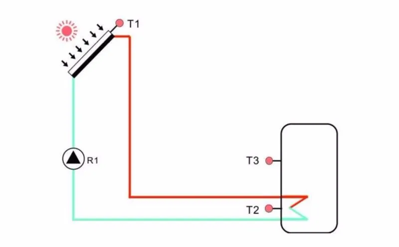
2. Технические характеристики
Источник питания: 100…240 В ~(50…60 Гц)
Номинальное импульсное напряжение: 2,5 кв
Корпус: Пластик из АБС-пластика
Монтаж: настенный монтаж
Эксплуатация: 10 кнопок на передней крышке
Тип защиты: IP40
1500 Вт (3000 Вт/4000 Вт электрического нагревателя можно заказать за дополнительную плату)
Размер дисплея: 120*120*23 мм
Размер платы контроллера с выходом 1500 Вт: 200*140*43 мм
Размер платы контроллера с 3000 Вт/4000 Вт Выход: 218*165*55 мм
Примечание: Есть 4 входа для NTC10K, B = 3950 датчика температуры, но только 2 датчика включены
В стандартном списке доставки; Остальные два должны быть приобретены отдельно клиентом при необходимости
3), поэтому пожалуйста, убедитесь, что адрес корректен перед покупкой. Прайс-лист
1 * SR91 контроллер
1 * сумка для аксессуаров
1 * Руководство пользователя
1 * PT1000 датчик температуры (& phi;6*50 мм, длина кабеля 1,5 м)
2 * NTC10K датчик температуры (& phi;6*50 мм, длина кабеля 3 метра)
1*10 А кабель питания (Примечание: контроллер для электрического нагревателя 3000 Вт не имеет кабеля питания, пользователь должен подготовить кабель 2,5 мм2)
Примечание: устройство должно быть расположено только в сухих внутренних комнатах. Пожалуйста, разделите маршрутизацию датчика
Провода и провода сети. Убедитесь, что контроллер, а также система не подвержены воздействию сильного
Электромагнитных полей. Для управления 3000 Вт/4000 Вт электрические нагреватели, дополнительный переключатель должен быть
Установлен, и кабель 2,5 мм2 должен использоваться для подключения электрического нагревателя к клеммам
Контроллер.
Основные функции
Время нагрева — Резервное Отопление
Круг — Циркуляция горячей воды
Загрузка — Настройка загрузки tank1
COL — подача заявки на коллектор
Классные — подача заявки на функцией охлаждения
AUX — подача заявки на вспомогательная функция
Человек — подача заявки на ручном режиме
BLPR — блокирующая функция защиты
OTDI — функция термической дезинфекции
FS контроль скорости потока и защита от сухого хода Насоса
UNIT—C-F переключение между единицами измерения
RST — подача заявки на заводские настройки
Проходят — набора пароля
Ручное Отопление
Эко-экономичный режим
Защита Функция
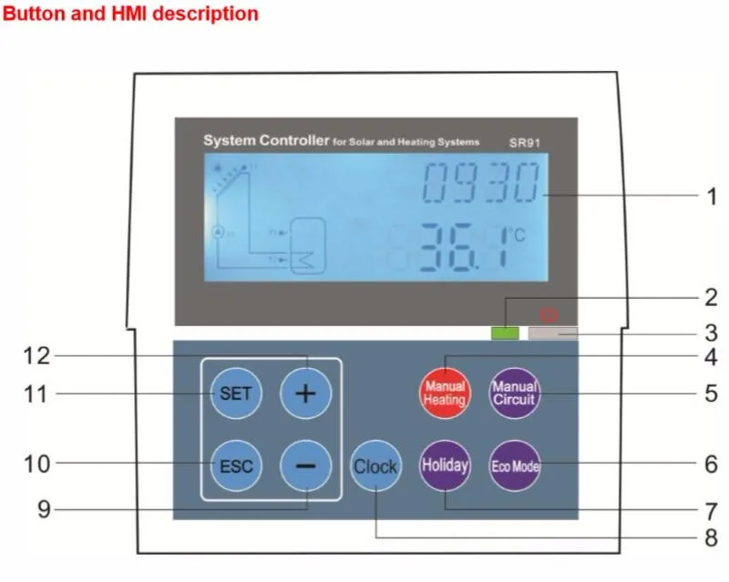
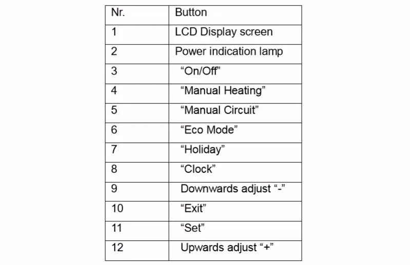
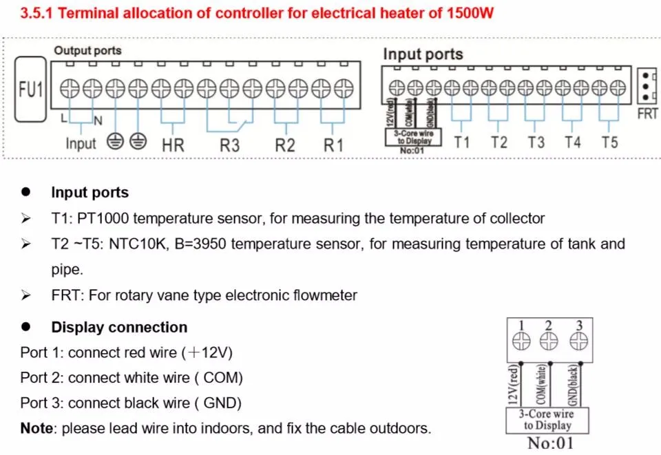
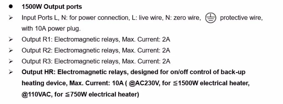
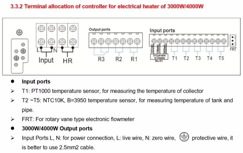
Доставка не будет производиться, даже если заказ размещен этими покупателями.Мы считаем, что все проблемы могут быть решены путем общения между покупателями и продавцами до тех пор, пока мы оба честны и понимаем.
ВНИМАНИЕ!
Автоматический перевод описания осуществляется только в текстовой форме. Информация, представленная поставщиком в виде картинок или надписей на фотографии, к сожалению не может быть переведена по техническим причинам. Показать оригинал описания данного товара.
Характеристики товара: |
|
| Цвет: | SR93-8Y-N-90-160R; SR93-8P-N-90-160R; SR93-8I-N-90-160R; SR93-8V-N-90-160R; SR93-8Y-N-90-140R; SR93-8P-N-90-140R; SR93-8I-N-90-140R; SR93-8V-N-90-140R; |
| Бренд: | SHIMADEN; |
| Модель: | SR93; |
| Место происхождения: | Японский; |
| Принцип работы: | Электронный термостат; |
| Власть: | 250V10A; |
| Диапазон температуры контроля температуры: | 1200; |
| Номер товара: | SR93; |
SR63, SR73, SR64, SR74, SR73A, SR74A устранены, модель была изменена на: SR93, SR94
Серия SR90 — это новейший технологический продукт Japan Electric Electric Company в 2002 году, в котором обобщается опыт применения SR60 до серии SR70 и подчеркивается идея дизайна высокой производительности и высокой надежности. При свободном вводе точность отображения 0,3, ручной выход, регулирует выходной ограничитель, двойное заданное значение, выход двойного регулятора, выход аналогового передатчика, возможности цифровой связи, передняя панель соответствует стандартам защиты IP66. Важно использовать экспертный алгоритм ПИД-алгоритма без перерасхода, два независимых набора параметров ПИД-регулятора, функционально завершенных и экономически эффективных по сравнению с серией SR73A / SR74A на острове. Более привлекательным для операторов является дисплей с большой яркостью с высокой яркостью с точностью 0,3% FS + 1-слов и 4 цикла выборки / отображения в секунду. Перед использованием системы вы можете запустить функцию автонастройки, чтобы найти лучшие параметры PID системы, чтобы упростить отладку на месте и улучшить качество настройки. Экспертный PID-алгоритм включает в себя фактор подавления выброса SF, разумный выбор, который может эффективно избежать перерегулирования системы или недогрузки. 0-100 секунд можно установить мощность при медленном запуске, до некоторой степени уменьшить ток перенапряжения, защитить устройство и продлить срок службы нагревательного элемента. Ограничитель выходной мощности можно использовать для ограничения размера отверстия клапана, чтобы избежать слишком большой мощности нагрева и специального нагревательного элемента нагревательной секции предела мощности. Вторая функция выхода (опция) может использоваться для регулировки нагрева / охлаждения или основного и вспомогательного контроля нагрева. Но также отрегулируйте DB мертвой зоны интервала двойного регулирования, чтобы достичь цели улучшения точности управления и экономии энергии. Управление дневным освещением теплицы или подогрев или прогрев системы отопления требует двойной настройки SB (опция), позволяя использовать один набор контактов. Чтобы предотвратить диапазон уставок, которые отклоняются от требований к процессу, используйте функцию заданного предела, чтобы избежать неправильной работы. Два независимых события. Реле может быть настроено на 9 видов событий, включая: верхнее и нижнее абсолютное значение, верхнее и нижнее отклонение, отклонение в / вне режима тревоги. Изолированный цифровой коммуникационный интерфейс (опционально), опциональный интерфейс RS232C, RS485, адрес порта 1 ~ 255. Он также может обеспечить интеллектуальный коммуникационный конвертер RS232 / 485 с оптической изоляцией Seaman с китайским программным обеспечением для настройки Windows Ximaden-e и главным компьютером для создания небольшой системы распространения. Моделирование передачи (опция): измеренное значение, заданное значение, значение отклонения, настройка выходной передачи, данные полевых записей, многозонный контроль температуры или регулировка каскада. Отключение однофазного нагревателя и сигнал отопительного контура (опция): Диапазон контроля тока: 0.0 ~ 30.0A и 0.0 ~ 50.0A. После калибровки датчика линейная ошибка или ошибка измерения, вызванная положением, могут быть установлены как смещение дисплея измеренного значения PV. Чтобы избежать помех измерения в полевых условиях, можно установить постоянную постоянную времени цифрового фильтра.
Япония SHIMADEN (остров) SR93 / SR94 0.3 Таблица выбора регулятора ПИД-регулятора
Япония SHIMADEN (остров) SR92 0.3 Таблица выбора ПИД-регулятора
Япония SHIMADEN (остров) SR91 0.3 Таблица выбора регулятора ПИД-регулятора
Пример заказа: SR93-8P-Y-90-1680 свободный вход, полупроводниковый релейный выход, второй выход — контакт, источник питания 100 ~ 240 В переменного тока, с выходом события, аналоговая отправка 0 ~ 10 В и двойная уставка