
РАЗДЕЛ 0B
ОБЩИЕ СВЕДЕНИЯ
ТЕХНИЧЕСКИЕ ХАРАКТЕРИСТИКИ
Технические данные
Характеристики ручной коробки передач с главной передачей в сборе
|
ПРОГРАММА
|
2,0 л двойной верх. распредвал
|
|
Максимальная скорость |
200 км/ч (124,3 мили/ч) |
|
Преодоление подъема |
0,663 (tan Ø) |
|
Минимальный радиус поворота |
5,2 м (17 футов) |
Характеристики автоматической коробки передач с главной передачей в сборе
|
ПРОГРАММА
|
2,0 л двойной верх. распредвал
|
|
Максимальная скорость |
190 км/ч (118,1 мили/ч) |
|
Преодоление подъема |
0,580 (tan Ø) |
|
Минимальный радиус поворота |
5,2 м (17 футов) |
Двигатель
|
ПРОГРАММА
|
2,0 л двойной верх. распредвал
|
|
Тип двигателя |
Однорядный 4 |
|
Диаметр цилиндров |
86,0 мм (3,39 дюйма) |
|
Ход поршня |
86,0 мм (3,39 дюйма) |
|
Полный объем двигателя |
1 998 куб. см. (121,9 дюйма³) |
|
Степень сжатия |
9.6 : 1 |
|
Макс. мощность |
96 кВт (128,7 л.с.) (при 5400 об/мин) |
|
Макс. крутящий момент |
181 Н•м (133,5 фунто-фута) (при 4200 об/мин) |
Система зажигания
|
ПРОГРАММА
|
2,0 л двойной верх. распредвал
|
|
Тип зажигания |
Система прямого зажигания |
|
Последовательность распределения тока по свечам зажигания |
1-3-4-2 |
|
Искровой промежуток |
1,0 мм (0,039 дюйма) |
|
Изготовитель свечей зажигания |
bosch |
|
Тип свечей зажигания |
flr8ldcu |
Сцепление
|
ПРОГРАММА
|
2,0 л двойной верх. распредвал
|
|
Тип |
Сухое, однодисковое |
|
Наружный диаметр |
225,0 мм (8,9 дюйма) |
|
Внутренний диаметр |
150,0 мм (5,9 дюйма) |
|
Толщина |
8,4 мм (0,3 дюйма) |
|
Вместимость жидкости |
Общего назначения; тормозная жидкость |
Механическая коробка передач с главной передачей в сборе
|
ПРОГРАММА
|
2,0 л двойной верх. распредвал
|
|
Изготовитель |
dwmc |
|
Тип или модель |
d-20 |
|
Передаточное число: |
. |
|
|
3.545 :1 2.048 :1 1.346 :1 0.971 :1 0.763 :1 3.333:1 |
|
Передаточное число главной передачи |
4.176:1 |
|
Вместимость масла |
1,8 л (2 кварты) |
Автоматическая коробка передач с главной передачей в сборе
|
ПРОГРАММА
|
2,0 л двойной верх. распредвал
|
|
Изготовитель |
zf |
|
Тип или модель |
4hp16 |
|
Передаточное число: |
. |
|
|
2.719 :1 1.487 :1 1.000 :1 0.717 :1 2.529 :1 |
|
Передаточное число главной передачи |
3.945 :1 |
|
Вместимость масла |
6,9 ± 0,2 л (7,3 ± 0,2 кварты) |
Тормозная система
|
ПРОГРАММА
|
2,0 л двойной верх. распредвал
|
|
Размер усилителя: (двойной) |
203,2 мм (8 дюймов) и 228,6 мм (9 дюймов) |
|
Диаметр главного барабана |
22,2 мм (0,87 дюйма) |
|
Передаточное число усилителя |
5.5 :1 |
|
Тормозные механизмы передних колес: |
. |
|
|
Вентилируемые 256 мм (10 дюймов) |
|
Тормозные механизмы задних колес: |
. |
|
|
Монолитный 258 мм (10,2 дюйма) |
|
Вместимость жидкости |
0,5 л (0,53 кварты) |
Шины и колеса
|
ПРОГРАММА
|
2,0 л двойной верх. распредвал
|
|
|
Размер шин |
205/65r15 |
205/55r16 |
|
Размер обода колеса |
6,0j x 15 (сталь) 6,0j x 15 (сплав) |
6,0j x 16 (сплав) |
|
Размер временной запасной шины |
125/70d16 |
|
|
Размер временного запасного колеса |
4t x 16 |
|
|
Давление в камере при полной нагрузке: |
||
|
|
230 кПа (33 фунта/кв. дюйм) 210 кПа (30 фунтов/кв. дюйм) |
|
|
|
|
|
|
|
210 кПа (30 фунтов/кв. дюйм) 210 кПа (30 фунтов/кв. дюйм) |
|
|
|
|
|
|
|
420 кПа (60 фунтов/кв. дюйм) 420 кПа (60 фунтов/кв. дюйм) |
Рулевое управление
|
ПРОГРАММА
|
2,0 л двойной верх. распредвал
|
|
Тип привода |
Механизм реечной передачи с гидроприводом |
|
Общее передаточное число: |
. |
|
|
|
|
Диаметр руля |
. |
|
|
390 мм (15,3 дюйма) 390 мм (15,3 дюйма) |
|
Регулировка установки колес: |
. |
|
|
|
|
|
6′ ± 10′ 3.0° ± 1.0° -30′ ± 1° |
|
|
|
|
|
9′ ± 10′ -1°30′ ± 1° |
|
Вместимость масла |
1,1 л (1,2 кварты) |
Подвеска
|
ПРОГРАММА
|
2,0 л двойной верх. распредвал
|
|
Передняя |
Стойки МакФерсона |
|
Задняя |
С набором тяг |
Система питания двигателя
|
ПРОГРАММА
|
2,0 л двойной верх. распредвал
|
|
Подача топлива |
Многоточ. инжектор |
|
Тип топливного насоса |
Насос с электродвигателем |
|
Тип топливного фильтра |
Патронный |
|
Вместимость топлива |
65 л (17,2 галлона) |
Система смазки
|
ПРОГРАММА
|
2,0 л двойной верх. распредвал
|
|
Вид смазки |
Принудительная подача |
|
Тип смазочного насоса |
Спиральный ротор |
|
Тип масляного фильтра |
Патронный (полнопоточный) |
|
Емкость поддона картера |
. |
|
Включая масляный фильтр |
4,0 л (4,2 кварты) |
Система охлаждения
|
ПРОГРАММА
|
2,0 л двойной верх. распредвал
|
|
Вид охлаждения |
Принудительная циркуляция воды |
|
Тип радиатора |
С гориз. располож. трубок |
|
Тип водяного насоса |
Центробежный |
|
Тип термостата |
С чувствительным элементом |
|
Вместимость охладителя |
7,5 л (7,9 кварты) |
Электрооборудование
|
ПРОГРАММА
|
2,0 л двойной верх. распредвал
|
|
Аккумулятор |
610 проворачивание коленвала непрогр. двиг. |
|
Генератор |
95 А |
|
Стартер (испытательный ток при отводе без нагрузки) |
1,4 кВт максимум 80 А 2550 мин-1 мин. (при 12 В) |
Габаритные размеры и весовые характеристики автомобиля
Габаритные размеры автомобиля
|
ПРОГРАММА
|
2,0 л двойной верх. распредвал
|
|
Общая длина |
4 770 мм (187,8 дюйма) |
|
Общая ширина |
1,815 мм (71,5 дюйма) |
|
Общая высота |
1 440 мм (56,7 дюйма) |
|
Минимальный дорожный просвет |
164 мм (6,4 дюйма) |
|
Колесная база |
2 700 мм (106,3 дюйма) |
|
Колея: |
. |
|
|
1 550 мм (61,0 дюйм) 1 535 мм (60,4 дюйма) |
Весовые характеристики автомобиля
|
ПРОГРАММА
|
2,0 л двойной верх. распредвал
|
|
Вручную: |
. |
|
|
1 422 ~ 1 469 кг (3 135,0 ~ 3 238,6 фунта) 1 912 кг (4 215,2 фунта) |
|
Автоматически: |
|
|
|
1 435 ~ 1 482 кг (3 163,6 ~ 3 267,3 фунта) 1 925 кг (4 243,9 фунта) |
|
Вместимость пассажиров |
5 |
Характеристики стандартизованных болтов
|
Болт*
|
4Т — малоуглеродистая сталь
|
7Т — высокоуглеродистая сталь
|
7Т — легированная сталь
|
|
М6 Х 1,0 |
4,1-8,1 Н•м (36-72 фунто-дюйма) |
5,4-9,5 Н•м (48-84 фунто-дюйма) |
— |
|
М8 Х 1,25 |
8,1-17,6 Н•м (72-156 фунто-дюймов) |
12,2-23,0 Н•м (108-204 фунто-дюйма) |
16-30 Н•м (12-22 фунто-фута) |
|
М10 Х 1,25 |
20-34 Н•м (15-25 фунто-футов) |
27-46 Н•м (20-34 фунто-фута) |
37-62 Н•м (27-46 фунто-футов) |
|
М10 Х 1,5 |
19-34 Н•м (14-25 фунто-футов) |
27-45 Н•м (20-33 фунто-фута) |
37-60 Н•м (27-44 фунто-фута) |
|
М12 Х 1,25 |
49-73 Н•м (36-54 фунто-фута) |
61-91 Н•м (45-67 фунто-футов) |
76-114 Н•м (56-84 фунто-фута) |
|
М12 Х 1,75 |
45-69 Н•м (33-51 фунто-фут) |
57-84 Н•м (42-62 фунто-фута) |
72-107 Н•м (53-79 фунто-футов) |
|
М14 Х 1,5 |
76-115 Н•м (56-85 фунто-футов) |
94-140 Н•м (69-103 фунто-фута) |
114-171 Н•м (84-126 фунто-футов) |
|
М14 Х 2,0 |
72-107 Н•м (53-79 фунто-футов) |
88-132 Н•м (65-97 фунто-футов) |
107-160 Н•м (79-118 фунто-футов) |
|
М16 Х 1,5 |
104-157 Н•м (77-116 фунто-футов) |
136-203 Н•м (100-150 фунто-футов) |
160-240 Н•м (118-177 фунто-футов) |
|
М16 Х 2,0 |
100-149 Н•м (74-110 фунто-футов) |
129-194 Н•м (95-143 фунто-фута) |
153-229 Н•м (113-169 фунто-футов) |
|
М18 Х 1,5 |
151-225 Н•м (111-166 фунто-футов) |
195-293 Н•м (144-216 фунто-футов) |
229-346 Н•м (169-255 фунто-футов) |
|
М20 Х 1,5 |
206-311 Н•м (152-229 фунто-футов) |
270-405 Н•м (199-299 фунто-футов) |
317-476 Н•м (234-351 фунто-фут) |
|
М22 Х 1,5 |
251-414 Н•м (185-305 фунто-футов) |
363-544 Н•м (268-401 фунто-фут) |
424-636 Н•м (313-469 фунто-футов) |
|
М24 Х 2,0 |
359-540 Н•м (265-398 фунто-футов) |
431-710 Н•м (318-524 фунто-фута) |
555-831 Н•м (409-613 фунто-футов) |
* Диаметр Х шаг в миллиметрах
ТЕХНИЧЕСКОЕ ОБСЛУЖИВАНИЕ И РЕМОНТ
ТЕХНИЧЕСКОЕ ОБСЛУЖИВАНИЕ И СМАЗКА
Обычная эксплуатация автомобиля
Приведенные в плане технического обслуживания указания по техническому обслуживанию должны соблюдаться при условии эксплуатации автомобиля в следующих случаях:
- Перевозка пассажиров и груза с соблюдением ограничений, указанных в предупреждении о шинах, которое можно найти на краю двери водителя.
- Езда по проезжей части с поверхностью приемлемого качества и с соблюдением нормативных допусков в эксплуатации.
Сведения о плановом техническом обслуживании
Приведенные в плане технического обслуживания мероприятия разъяснены ниже. При осуществлении технического обслуживания убедитесь в том, что до начала управления автомобилем произведена замена всех деталей и выполнен весь необходимый ремонт. Используйте только соответствующие жидкости и смазочные материалы.
Осмотр приводного ремня
Если насос рулевого привода с усилителем, компрессор для кондиционирования воздуха и генератор приводятся в действие отдельным ремнем, необходимо его проверить на наличие трещин, истирания, износа, а также правильность его натяжения. Отрегулируйте натяжение ремня или при необходимости замените его.
Замена моторного масла и масляного фильтра
Международный комитет по стандартизации и испытанию смазочных материалов (ILSAC) и Американский нефтяной институт классифицируют моторные масла по их рабочим характеристикам. Используйте масло только класса API-SL (ILSAC GF-III) или более высокого качества.
Вязкость моторного масла
Вязкость моторного масла (густота) сказывается на экономии топлива и эксплуатации в холодную погоду. Моторные масла с меньшей вязкостью позволяют экономить больше топлива и повышают эксплуатационные качества в холодную погоду; однако при повышении температуры окружающей среды для удовлетворительной смазки необходимы моторные масла с большей вязкостью. Если использовать масла с вязкостью, отличной от рекомендованной, можно повредить двигатель.
Техническое обслуживание системы охлаждения
Замена топливного микрофильтра
Заменяйте топливный фильтр двигателя через каждые 45000 км (30000 миль).
Замена элемента воздушного фильтра
Заменяйте элемент воздушного фильтра через каждые 45000 км (30000 миль).
В условиях запыленности заменяйте воздушный фильтр чаще.
Момент затяжки монтажных болтов на корпусе дроссельной заслонки
Проверяйте момент затяжки монтажных болтов на корпусе дроссельной заслонки.
Затянуть
При необходимости подтяните монтажные болты на корпусе дроссельной заслонки до 10 Н•м (89 фунто-дюймов).
Замена свеч зажигания
Заменяйте свечи зажигания на другие того же типа.
Замена проводов свечей зажигания
Очистите провода и проверьте, нет ли на них следов ожогов, трещин или другого повреждения. Проверяйте надежность посадки защитного колпачка вывода на модуле системы прямого зажигания (DIS) и на свечах зажигания. При необходимости замените провода.
Техническое обслуживание тормозной системы
Проверяйте колодки дисковых тормозных механизмов через каждые 15000 км (10000 миль) или 12 месяцев. Тщательно проверяйте толщину колодок. Если колодки не выдержат еще 15000 км (10000 миль) пробега, замените их. Убедитесь в отсутствии загрязнения и открытости прохода во всасывающей трубке крышки бачка с тормозной жидкостью.
Техническое обслуживание коробки передач с главной передачей в сборе
Замена жидкости для механической коробки передач с главной передачей в сборе не нужна. Насчет автоматических коробок передач с главной передачей в сборе смотрите «Карты планового технического обслуживания» в данном разделе.
Проверка и поворот шин и колес
Проверьте, нет ли у шин неестественного износа или повреждений. Для того, чтобы равномерно распределить износ и максимально продлить срок службы шин, поверните их. При неравномерном или преждевременном износе проверьте регулировку установки колес и отсутствие у них повреждений. При снятых колесах и шинах проверьте состояние тормозных механизмов. Смотрите «При каждой замене масла» в данном разделе.


Карты планового технического обслуживания
Двигатель
|
Обслуживаемый узел
|
Интервал технического обслуживания
|
|||||||
|
.
|
Километры или время в месяцах, в зависимости от того, что наступит раньше
|
|||||||
|
х 1000 км
|
15
|
30
|
45
|
60
|
75
|
90
|
105
|
120
|
|
х 1000 миль
|
10
|
20
|
30
|
40
|
50
|
60
|
70
|
80
|
|
Месяцы
|
12
|
24
|
36
|
48
|
60
|
72
|
84
|
96
|
| Приводные ремни (генератор, рулевой привод с усилителем и ремень кондиционера воздуха) | i | i | i | i | ||||
| Моторное масло и фильтр моторного масла (1) (3) | r | r | r | r | r | r | r | r |
| Шланговые соединения системы охлаждения | i | i | i | i | i | i | i | i |
|
Охлаждающая жидкость двигателя (3) |
i |
i |
r |
i |
i |
r |
i |
i |
|
Топливный фильтр |
. |
. |
r |
. |
. |
r |
. |
. |
|
Топливопровод и соединения |
i |
i |
i |
i |
i |
i |
i |
i |
|
Элемент воздушного фильтра (2) |
i |
i |
r |
i |
i |
r |
i |
i |
|
cвечи зажигания |
. |
i |
. |
r |
. |
i |
. |
r |
|
Провода свечей зажигания |
Заменять через каждые 96000 км (60000 миль) |
|||||||
|
Система улавливания паров топлива, паропроводы и фильтр электромагнитного клапана |
. |
. |
i |
. |
. |
i |
. |
. |
|
Система вентиляции картера |
. |
i |
. |
i |
. |
i |
. |
i |
|
Зубчатый ремень привода |
. |
i |
. |
r |
. |
i |
. |
r |
Символьные обозначения карты:
I — проверить эти узлы и связанные с ними детали. При необходимости исправьте, очистите, добавьте, отрегулируйте или замените.
R — замена или смена:
(1) Заменяйте моторное масло и масляный фильтр через каждые 7500 км (5000 миль) или 6 месяцев, в зависимости от того что наступит раньше, при эксплуатации автомобиля при любых из нижеперечисленных условиях:
- Езда на короткое расстояние.
- Длительная работа на холостом ходу.
- Езда при сильной запыленности.
(2) Проверяйте состояние элемента воздушного фильтра через каждые 7500 км (5000 миль) или 6 месяцев при езде в условиях запыленности. При необходимости исправить, очистить или заменить.
Шасси и кузов
|
Обслуживаемый узел
|
Интервал технического обслуживания
|
|||||||
|
.
|
Километры или время в месяцах, в зависимости от того, что наступит раньше
|
|||||||
|
х 1000 км
|
15
|
30
|
45
|
60
|
75
|
90
|
105
|
120
|
|
х 1000 миль
|
9
|
18
|
27
|
36
|
45
|
54
|
63
|
72
|
|
Месяцы
|
12
|
24
|
36
|
48
|
60
|
72
|
84
|
96
|
| Воздушный фильтр салона (кондиционер воздуха) (6) | r | r | r | r | r | r | r | r |
| Выхлопные трубы и подвески | i | i | i | i | i | i | i | i |
| Тормозная жидкость/жидкость для гидропривода выключения сцепления (1) (4) | i | r | i | r | i | r | i | r |
|
Колодки и диски тормозных механизмов передних колес (3) |
i |
i |
i |
i |
i |
i |
i |
i |
|
Колодки и диски или барабаны и накладки тормозных механизмов задних колес (3) |
i |
i |
i |
i |
i |
i |
i |
i |
|
Стояночная тормозная система |
i |
i |
i |
i |
i |
i |
i |
i |
|
Тормозная магистраль и соединения (включая усилитель) |
i |
i |
i |
i |
i |
i |
i |
i |
|
Масло механической коробки передач с главной передачей в сборе *(1) |
i |
i |
i |
i |
i |
i |
i |
i |
|
Жидкость для автоматической коробки передач с главной передачей в сборе *(1) (5) |
i |
i |
i |
i |
i |
i |
i |
i |
|
Затяжка болтов и гаек на шасси и нижней части кузова |
i |
i |
i |
i |
i |
i |
i |
i |
|
Регулировка установки колес (2) |
Осмотрите при обнаружении отклонений от нормы |
|||||||
|
Рулевое управление и рычажный механизм |
i |
i |
i |
i |
i |
i |
i |
i |
|
Жидкость для рулевого привода с усилителем и трубопровода* (1) |
i |
i |
i |
i |
i |
i |
i |
i |
|
Защитная оболочка карданного вала |
i |
i |
i |
i |
i |
i |
i |
i |
|
Ремни безопасности, пряжки и фиксаторы |
i |
i |
i |
i |
i |
i |
i |
i |
|
Смазка замков, петель и защелки крышки капота |
i |
i |
i |
i |
i |
i |
i |
i |
Символьные обозначения карты:
I — Осмотрите и при необходимости исправьте, очистите, добавьте или отрегулируйте.
R — замена или смена:
(2) При необходимости проверните колеса и выполните их балансировку.
(3) Техническое обслуживание требуется проводить чаще при эксплуатации в следующих условиях с повышенной нагрузкой: езда на короткие расстояния, длительная работа на холостом ходу, частое использование пониженных передач при городском цикле движения или езда при сильной запыленности.
(4) Меняйте тормозную жидкость/жидкость для гидропривода выключения сцепления через каждые 15000 км (10000 миль), если автомобиль эксплуатируется в основном в следующих условиях с повышенной нагрузкой: езда по холмистой или гористой местности или частое буксирование прицепа или фургона.
(5) Заменяйте жидкость для автоматической коробки передач с главной передачей в сборе через каждые 60000 км (40000 км), если автомобиль эксплуатируется в основном в любых из нижеследующих тяжелых условий:
- При городском цикле интенсивного движения, когда температура окружающей среды обычно достигает 32°С (90°f) или выше, либо
- На холмистой или гористой местности либо
- При частом буксировании прицепа либо
- При эксплуатации в качестве, например, такси, полицейской машины или средства доставки.
(6) При эксплуатации в условиях запыленности требуется чаще проводить техническое обслуживание.
ТЕХНИЧЕСКОЕ ОБСЛУЖИВАНИЕ И ПРОВЕРКИ, ВЫПОЛНЯЕМЫЕ ВЛАДЕЛЬЦЕМ
При эксплуатации автомобиля
Эксплуатация звукового сигнала
Временами проверяйте работоспособность звукового сигнала. Проверяйте расположение всех кнопок.
Эксплуатация тормозной системы
Подмечайте необычные звуки, увеличенный ход педали тормоза или частый увод в сторону при торможении. Также если загорелся или мигает сигнализатор аварийного состояния тормозной системы, возможно, что-то произошло с частью тормозной системы.
Эксплуатация системы выпуска отработавших газов
Подмечайте любые изменения в звуках, сопровождающих работу этой системы, или запахе выхлопных газов. Это может указывать на утечку в системе или ее перегрев. Систему необходимо немедленно проверить и отремонтировать.
Эксплуатация шин, колес и их отрегулированность
Подмечайте любую вибрацию руля или сидений на обычной скорости движения по шоссе. Если это возникло, возможно, необходима балансировка одного из колес. Также увод вправо или влево при движении по прямой, ровной дороге может указывать на необходимость корректировки давления в шинах или регулировки установки колес.
Эксплуатация рулевого управления
Подмечайте изменения в поведении рулевого управления. Осмотр необходим, если руль стало трудно поворачивать или люфт руля значительно увеличился либо если появились необычные звуки при повороте или остановке.
Наклон пучка света фар
Время от времени проверяйте правильность наклона пучка света фар. Если пучок света падает неправильно, выполните регулировку фар.
При каждой заливке топлива
Исчезновение жидкости в любой из систем (кроме омывателя ветрового стекла) может указывать на нарушение. Систему необходимо немедленно проверить и отремонтировать.
Уровень масла в двигателе
Контролируйте уровень масла и при необходимости масло доливайте. Лучше всего проверять уровень масла тогда, когда оно теплое.
- Заглушив двигатель, подождите несколько минут, пока масло не стечет обратно в поддон картера.
- Вытащите указатель уровня масла (погружной).
- Протрите указатель уровня масла и вставьте его назад, задвинув полностью вниз.
- Вытащите указатель уровня масла и определите по нему уровень масла.
- При необходимости долейте масло, чтобы его уровень находился выше отметки min, в пределах участка, помеченного как «рабочий диапазон» («Operating Range»). Не заливайте масло в двигатель больше положенного, иначе можно повредить двигатель.
- Узнав уровень масла, полностью задвиньте указатель обратно в двигатель.
Если проверяется уровень холодного масла, перед этим не запускайте двигатель. Холодное масло не будет стекать в поддон настолько быстро, чтобы можно было узнать точный его уровень.
Уровень и состояние охлаждающей жидкости двигателя
Проверяйте уровень охлаждающей жидкости в бачке системы охлаждения и при необходимости ее доливайте. Проверьте охлаждающую жидкость. Замените загрязненную или отработавшую охлаждающую жидкость.
Уровень жидкости омывателя ветрового стекла
Проверьте уровень жидкости омывателя ветрового стекла в бачке. При необходимости долейте жидкость.
Минимум раз месяц
Осмотр шин и колес и проверка давления
Проверьте, нет ли у шин неестественного износа или повреждений. Также необходима проверка колес на наличие повреждений. Проверяйте давление в шинах тогда, когда они находятся в холодном состоянии (вместе с запасным колесом, если оно не уложено в специальный отсек). Поддерживайте рекомендуемое давление в шинах, приведенное на табличке с данными в вещевом ящике.
Использование освещения и световой сигнализации
Проверяйте работу подсветки номерного знака, фар (включая фары дальнего света), ламп стоп-сигнала, противотуманных фар, заднего габаритного фонаря, указателей поворотов, ламп света заднего хода и аварийной сигнализации.
Проверка утечки эксплуатационных жидкостей
Периодически следите за тем, нет ли на поверхности под автомобилем следов воды, масла, эксплуатационных жидкостей после того, как автомобиль некоторое время простаивал. Капли воды, появляющиеся из системы кондиционирования воздуха после ее работы — это нормальное явление. Если замечена утечка топлива или выхлопных газов, определите причину и исправьте это нарушение.
Минимум раз в два года
Уровень жидкости в бачке системы рулевого привода с усилителем
Уровень жидкости в бачке гидропривода главного тормозного барабана
Проверьте уровень жидкости и поддерживайте ее необходимый уровень. Понижение уровня жидкости может отразиться на износе колодок дисковых тормозных механизмов, которые могут потребовать ремонта. Убедитесь в отсутствии загрязнения и открытости прохода во всасывающей трубке крышки бачка.
Свободный ход педали сцепления
Проверьте ход педали сцепления и при необходимости отрегулируйте его. Измерьте расстояние от центра педали сцепления до наружного края руля при ненажатой педали сцепления. Затем измерьте расстояние от центра педали сцепления до наружного края руля при полностью утопленной педали сцепления. Разница между этими двумя значениями должна быть больше 130 мм (5,19 дюйма).
Смазка прокладок
Нанесите тонкий слой силиконовой консистентной смазки с помощью чистой ткани.
При каждой замене масла
Жидкость для автоматической коробки передач с главной передачей в сборе
Механическая коробка передач с главной передачей в сборе
Осмотр тормозной системы
Такой осмотр следует проводить при снятии колес для вращения. Проверьте надежность прицепления, соединения проводов и шлангов, нет ли в них утечки, трещин, износа и т.д. Проверьте изношенность колодок дисковых тормозных механизмов. Проверьте состояние поверхности рабочих колес. Проверяйте другие узлы тормозной системы, включая стояночную тормозную систему и проч., одновременно. Проверьте, как отрегулирована стояночная тормозная система. Осматривайте тормозные механизмы чаще, если вам приходится часто тормозить.
Осмотр рулевого управления, подвесок и защитной оболочки и уплотнений моста с передним приводом
Проверьте передние и задние подвески и рулевое управление на наличие повреждений, не ослабли ли отдельные детали, не пропали ли они, нет ли износа или достаточно ли они смазаны. Проверьте надежность прицепления, соединения проводов и шлангов рулевого привода с усилителем, нет ли в них утечки, трещин и износа и т.д. Очистите защитную оболочку и уплотнения ведущего моста и проверьте их на наличие повреждений, разрывов или утечки. При необходимости уплотнения замените.
Осмотр системы выпуска отработавших газов
Проверьте всю систему (включая каталитический дожигатель выхлопных газов, если таковой установлен). Осмотрите кузов возле системы выпуска отработавших газов. Проверьте на наличие разрывов, повреждений детали, не пропали ли они и установлены ли они в нужном положении, проверьте также стыки, отверстия, плотность соединений или все то, что может привести к скоплению тепла в днище кузова или просачиванию выхлопных газов в багажник или салон автомобиля.
Проверка тяг управления дроссельной заслонкой
Проверьте плавность работы тяг управления дроссельной заслонкой или надежность их соединения, не повреждены ли они, не пропали ли отдельные детали. Смажьте подходящей консистентной смазкой все шарниры и соединения троса привода дроссельной заслонки, промежуточный подшипник валика газа, пружину возврата у блока дроссельного клапана и поверхность скольжения педали газа. Проверьте свободу перемещения троса привода дроссельной заслонки.
Приводные ремни двигателя
Проверьте все ремни на наличие трещин, истирания, износа и правильность их натяжения. Отрегулируйте натяжение ремней или при необходимости замените их.
Эксплуатация защелки капота
При открытии капота проверьте работоспособность дополнительной защелки. Она не должна допускать полного открытия капота при освобождении основной защелки. Капот должен плотно закрываться.
Минимум раз в год
Состояние и эксплуатация поясных и чересплечных ремней безопасности
Осмотрите систему ремней безопасности, включая следующее: тканые ремни, пряжки, язычки защелок, натяжитель, направляющие скобы и фиксаторы.
Эксплуатация подвижных подголовников
У автомобилей с подвижными подголовниками подголовники должны находиться в желаемом положении.
Хранение запасного колеса и домкрата
Обращайте внимание на грохот в задней части автомобиля. Запасное колесо, оборудование для поддомкрачивания и инструмент должны быть всегда надежно сложены. После каждого использования необходимо смазывать трещотку домкрата или винтовой механизм.
Эксплуатация замков
Смазывайте цилиндры замков.
Смазка деталей кузова
Смазывайте все петли дверей кузова, включая капот, крышку лючка, петли и защелки заднего отсека, крышки вещевого ящика и приборной панели, а также любые крепежные детали складывающихся сидений.
Использование переключателя нейтрали в автоматической коробке передач с главной передачей в сборе
Внимание! Соблюдайте следующие меры предосторожности. При их несоблюдении возможны травмы и нанесение ущерба имуществу.
- Надежно затяните стояночный тормоз и приведите в действие основные тормозные механизмы.
- Не используйте педаль газа.
- При запуске двигателя будьте готовы выключить зажигание.
У автомобилей с автоматической коробкой передач с главной передачей в сборе попробуйте завести двигатель на каждой передаче. Стартер должен проворачивать коленвал только в положении Р (ПАРКОВКА) и N (НЕЙТРАЛЬ).
Эксплуатация стояночной тормозной системы и механизма парковки (Р) коробки передач с главной передачей в сборе
Внимание! Для снижения опасности получения травмы или нанесения ущерба имуществу будьте готовы привести в действие основные тормоза, если автомобиль начнет двигаться.
Припаркуйте автомобиль на достаточно крутом склоне, где есть достаточно места для движения вниз. Для проверки стояночной тормозной системы необходимо при работающем двигателе и положении N (нейтраль) коробки передач с главной передачей в сборе медленно отпустить педаль тормоза (настолько, чтобы автомобиль удерживался только стояночным тормозом).
Для проверки удерживающей способности механизма парковки (Р) автоматической коробки передач с главной передачей в сборе освободите автомобиль от всех тормозов после переключения коробки передач в положение Р (парковка).
Промывка нижней части кузова
Промывка нижней части кузова используется для удаления всех коррозирующих материалов, используемых при обледенении и ликвидации снега, а также уменьшении запыленности. Очищайте нижнюю часть кузова минимум каждую весну. Сначала необходимо снять наслоения, скопившиеся на закрытых участках автомобиля. Затем промойте нижнюю часть кузова простой водой.
Система охлаждения двигателя
Проверьте состояние охлаждающей жидкости и антифриза. Если жидкость загрязнена или отработана, слейте, прокачайте ее и залейте в систему охлаждения двигателя новую охлаждающую жидкость. Поддерживайте нужную пропорцию смешивания с охлаждающей жидкостью для обеспечения необходимой защиты от замерзания, коррозии и рабочей температуры двигателя. Проверьте шланги. Замените потрескавшиеся, вздутые или поврежденные шланги. Затяните зажимы. Очистите наружную часть радиатора и конденсатора установки для кондиционирования воздуха. Промойте крышку заливной горловины и горловину. Проверьте давление в системе охлаждения и крышке, чтобы система работала нормально.
Рекомендуемые горюче-смазочные материалы и эксплуатационные жидкости
|
Применение
|
Вместимость
|
Эксплуат. жидкость/смаз. материал
|
|
Моторное масло |
4,0 л (4,2 кварты) |
Марка api sl (ilsac gf-iii) sae 5w-30 Жаркая зона : sae 10w-30 |
|
Охлаждающая жидкость двигателя |
7,5 л (7,9 кварты) |
Смесь воды и высококачественного антифриза на силикатной основе (круглогодичное охлаждающее средство) |
|
Тормозная жидкость и жидкость для выключения сцепления |
0,5 л (0,5 кварты) |
dot-3 или dot-4 |
|
Жидкость системы рулевого привода с усилителем |
1,1 л (1,2 кварты) |
dexron®-iii, dexron®ii-d |
|
Автоматическая коробка передач с главной передачей в сборе |
6,9 ± 0,2 л (7,3 ± 0,2 кварты) |
esso lt 71141 или total atf h50235 |
|
Механическая коробка передач с главной передачей в сборе |
1,8 л (2 кварты) |
sae80 Очень холодная зона: sae 75w |
|
Рычажный механизм переключения механической коробки передач с главной передачей в сборе |
При необходимости |
Многоцелевая консистентная смазка, отвечающая требованиям nlgi № 1 или 2 |
|
Цилиндры замков |
При необходимости |
Силиконовая смазка |
|
Рычажный механизм переключения автоматической коробки передач с главной передачей в сборе |
При необходимости |
Моторное масло |
|
Оси поворота рычажного механизма выключения сцепления |
При необходимости |
Моторное масло |
|
Шарниры навесных устройств переключения в днище |
При необходимости |
Моторное масло |
|
Узел защелки капота
|
При необходимости |
|
|
Петли крышки капота и дверей Петля крышки лючка Петли крышки заднего отсека |
При необходимости |
Моторное масло |
|
Герметик |
При необходимости |
Силиконовая консистентная смазка |
ОБЩЕЕ ОПИСАНИЕ И РАБОТА СИСТЕМЫ
Общие указания по ремонту
При использовании домкрата, подставляемого под днище, рекомендуются следующие меры предосторожности:
- Остановите автомобиль на ровной поверхности, «заблокируйте» передние или задние колеса, уприте домкрат в раму, поднимите автомобиль, подоприте шасси стойками и затем приступите к техобслуживанию.
- Перед операцией по техобслуживанию отсоедините отрицательный кабель аккумулятора, уменьшив вероятность повреждения и опаливания кабеля в случае короткого замыкания.
- Покрывайте подходящим материалом кузов, сидения и днище для их защиты от повреждения и загрязнения.
- Аккуратно обращайтесь с тормозной жидкостью и антифризом, так как они могут повредить лакокрасочное покрытие.
- Для эффективного и надежного выполнения техобслуживания и ремонта важно применять соответствующий инструмент, а также, когда это необходимо, основной и имеющий рекомендуемый инструмент.
- Используйте только рекомендованные фабричные детали.
- Использованные шплинты, прокладки, уплотнительные кольца, контровочные шайбы, зажимы с угловым моментом затяжки и самозамыкающиеся гайки дальнейшему использованию не подлежат. При сборке приготовьте им замену. При повторном их использовании нельзя добиться их нормальной работоспособности.
- Разобранные детали аккуратно складывайте группами, чтобы упростить обратную сборку в нужной последовательности.
- Держите крепежные болты и гайки отдельно, поскольку они отличаются по твердости и конструкции с учетом места установки.
- Перед осмотром или повторной сборкой детали необходимо очищать.
- Очищайте также маслосодержащие детали и проч. Для устранения в них каких-либо препятствий необходимо использовать сжатый воздух.
- Перед установкой смазывайте вращающиеся и скользящие лицевые стороны деталей маслом или смазкой.
- Если нужно добиться необходимой герметичности, наносите на прокладки герметик.
- Строго соблюдайте все указываемые моменты затяжки для болтов и гаек.
После выполнения техобслуживания или ремонта окончательно проверьте правильность выполненных операций и устранения неисправности.
ОБЩЕЕ ОПИСАНИЕ
Система обозначения комплектующих и автомобиля
Идентификационный номер легкового автомобиля — тип eu
Расположение таблички с идентификационным номером автомобиля
Табличка с идентификационным номером автомобиля (VIN) прикреплена к верхней части стойки передней панели.

Табличка с идентификационным номером автомобиля

- Производитель
- Номер nta или номер wvta
- Идентификационный номер автомобиля
- Полная масса автомобиля
- Комбинированная масса
- Масса переднего моста
- Масса заднего моста
Расположение выбитого номера vin

Идентификационный номер автомобиля (VIN) выбит в верхней правой части переборки.
Расположение номера двигателя

Номер двигателя проштампован на блоке цилиндров под выпускным коллектором двигателя № 4.
Номер двигателя
Табличка с идентификационным номером кузова

- Номер заказа
- Контрольная цифра
- Привод
- Тип кузова
- Месяц производства
- Дата производства
- Порядковый номер
- Крышка багажника
- Цвет снаружи
- Страна экспорта
- Тип автомобиля
Расположение таблички с идентификационным номером кузова

Табличка с идентификационным номером кузова прикреплена к верхней части стойки передней панели.
Табличка с идентификационным номером механической коробки передач

- Идентификационный код
- Порядковый номер
|
Идентификационный код
|
Двигатель
|
Передаточное число
|
|
fd |
2,0 л двойной верх. распредвал |
4,176 СРЕДН. |
Расположение таблички с идентификационным номером механической коробки передач с главной передачей в сборе

Идентификационный номер механической коробки передач с главной передачей в сборе прикреплен к верхней части картера коробки передач рядом с двигателем.
Табличка с идентификационным номером автоматической коробки передач (zf 4hp 16)
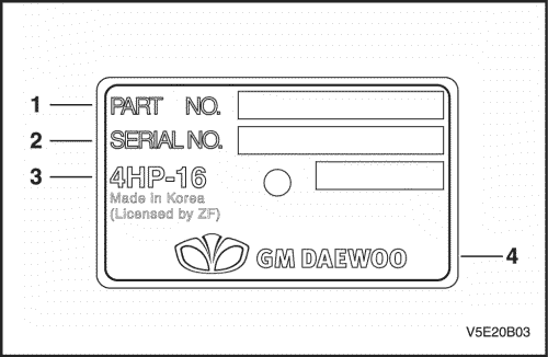
- Номер детали
- Серийный номер
- Код модели
- Государство и компания, в которых было осуществлено производство
|
Код детали
|
Двигатель
|
|
bd |
2,0 л двойной верх. распредвал |
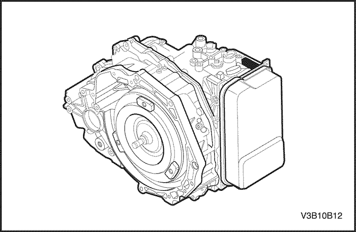
Расположение таблички с идентификационным номером автоматической коробки передач с главной передачей в сборе
Процедуры подъема автомобиля
Примечание: Для подъема автомобиля располагайте подъемное оборудование только в указанных точках. При несоблюдении таких точных мест может возникнуть постоянная деформация кузова.
Примечание: Многие сервисные центры и сервисные станции дилеров оснащены специальными подъемниками, которые для подъема автомобиля опираются на определенные участки конструкции. При использовании какого-либо способа подъема проявляйте осторожность, чтобы не повредить топливный бак, наливную горловину, систему выпуска отработавших газов или нижнюю часть кузова.
Точки подъема автомобиля
Точки подъема автомобиля

Evanda
SECTION 0B
GENERAL INFORMATION
SPECIFICATIONS
Technical Data
Performance — Manual Transaxle
|
Application |
2.0L DOHC |
|
|
Maximum Speed |
200 km/h (124.3 mph) |
|
|
Gradeability |
0.663 (tan Ø) |
|
|
Minimum Turning Radius |
5.2 m (17 ft) |
|
|
Performance — Automatic Transaxle |
||
|
Application |
2.0L DOHC |
|
|
Maximum Speed |
190 km/h (118.1 mph) |
|
|
Gradeability |
0.580 (tan Ø) |
|
|
Minimum Turning Radius |
5.2 m (17 ft) |
|
|
Engine |
||
|
Application |
2.0L DOHC |
|
|
Engine Type |
In-line 4 |
|
|
Bore |
86.0 mm (3.39 in.) |
|
|
Stroke |
86.0 mm (3.39 in.) |
|
|
Total Displacement |
1998 cc (121.9 in³) |
|
|
Compression Ratio |
9.6 : 1 |
|
|
Maximum Power |
96 kW (128.7 hp) |
|
|
(at 5,400 rpm) |
||
|
181 N•m (133.5 lb-ft) |
||
|
Maximum Torque |
(at 4,200 rpm) |
|
|
Ignition System |
||
|
Application |
2.0L DOHC |
|
|
Ignition Type |
Direct Ignition System |
|
|
Ignition Timing |
8° (BTDC) |
|
|
Ignition Sequence |
1-3-4-2 |

|
Application |
2.0L DOHC |
|
|
Spark Plug Gap |
1.0 mm (0.039 in) |
|
|
Spark Plug Maker |
Bosch |
|
|
Spark Plug Type |
FLR8LDCU |
|
|
Clutch |
||
|
Application |
2.0L DOHC |
|
|
Type |
Single Dry Plate |
|
|
Outside Diameter |
225.0 mm (8.9 in.) |
|
|
Inside Diameter |
150.0 mm (5.9 in.) |
|
|
Thickness |
8.4 mm (0.3 in.) |
|
|
Fluid Capacity |
Common Use; Brake Fluid |
|
|
Manual Transaxle |
||
|
Application |
2.0L DOHC |
|
|
Maker |
DWMC |
|
|
Type or Model |
D-20 |
|
|
Gear Ratio: |
. |
|
|
1st |
3.545 :1 |
|
|
2nd |
2.048 :1 |
|
|
3rd |
1.346 :1 |
|
|
4th |
0.971 :1 |
|
|
5th |
0.763 :1 |
|
|
Reverse |
3.333:1 |
|
|
Final Drive Ratio |
4.176:1 |
|
|
Oil Capacity |
1.8L (2 qt) |
|
|
Automatic Transaxle |
||
|
Application |
2.0L DOHC |
|
|
Maker |
ZF |
|
|
Type or Model |
4HP16 |
|
|
Gear Ratio: |
. |
|
|
1st |
2.719 :1 |
|
|
2nd |
1.487 :1 |
|
|
3rd |
1.000 :1 |
|
|
4th |
0.717 :1 |
|
|
Reverse |
2.529 :1 |
|
|
Final Drive Ratio |
3.945 :1 |
|
|
Oil Capacity |
6.9 ± 0.2 L (7.3 ± 0.2 qt) |
|
|
Brake |
||
|
Application |
2.0L DOHC |

|
Application |
2.0L DOHC |
||||
|
Booster Size: (Dual) |
203.2 mm (8 in) and 228.6 mm (9 in) |
||||
|
Master Cylinder Diameter |
22.2 mm (0.87 in.) |
||||
|
Booster Ratio |
5.5 :1 |
||||
|
Front Brake: |
. |
||||
|
Disc Type |
Ventilated |
||||
|
Disc Size |
256 mm (10 in.) |
||||
|
Rear Brake: |
. |
||||
|
Disc Type |
Solid |
||||
|
Disc Size |
258 mm (10.2 in.) |
||||
|
Fluid Capacity |
0.5L (0.53 qt) |
||||
|
Tire and Wheel |
|||||
|
Application |
2.0L DOHC |
||||
|
Tire Size |
205/65R15 |
205/55R16 |
195/70R 14 |
||
|
Wheel Size |
6.0J x 15 (steel) |
6.0J x 16 (Alloy) |
5.5J x 14 (Steel) |
||
|
6.0J x 15 (Alloy) |
|||||
|
Inflation Pressure at Full |
. |
||||
|
Load: |
|||||
|
205/65R15: |
. |
||||
|
Front |
230 kPa (33 psi) |
||||
|
Rear |
210 kPa (30 psi) |
||||
|
205/55R16: |
. |
||||
|
Front |
210 kPa (30 psi) |
||||
|
Rear |
210 kPa (30 psi) |
||||
|
195/70R14: |
. |
||||
|
Front |
210 kPa (30 psi) |
||||
|
Rear |
210 kPa (30 psi) |
||||
|
Steering System |
|||||
|
Application |
2.0L DOHC |
||||
|
Gear Type |
Power |
||||
|
Rack and Pinion |
|||||
|
Overall Gear Ratio: |
. |
||||
|
Power Steering |
17 : 1 |
||||
|
Wheel Diameter |
. |
||||
|
W/ Air Bag |
390 mm (15.3 in.) |
||||
|
W/O Air Bag |
390 mm (15.3 in.) |
||||
|
Wheel Alignment: |
. |
||||
|
(Based on 2 Occupants) |
|||||
|
Front: |
|||||
|
Toe-In |
6′ ± 10′ |
||||

|
Application |
2.0L DOHC |
|
|
Caster |
3.0° ± 1.0° |
|
|
Camber |
-30′ ± 1° |
|
|
Rear: |
||
|
Toe-In |
9′ ± 10′ |
|
|
Camber |
-1°30′ ± 1° |
|
|
Oil Capacity |
1.1L (1.2 qt) |
|
|
Suspension |
||
|
Application |
2.0L DOHC |
|
|
Front Type |
McPherson Strut |
|
|
Rear Type |
Multilink Type |
|
|
Fuel System |
||
|
Application |
2.0L DOHC |
|
|
Fuel Delivery |
MPI |
|
|
Fuel Pump Type |
Electric Motor Pump |
|
|
Fuel Filter Type |
Cartridge |
|
|
Fuel Capacity |
65L (17.2 gal) |
|
|
Lubricating System |
||
|
Application |
2.0L DOHC |
|
|
Lubricating Type |
Forced Feed |
|
|
Oil Pump Type |
Duocentric Rotor |
|
|
Oil Filter Type |
Cartridge (Full Flow) |
|
|
Oil Pan Capacity |
. |
|
|
Including Oil Filter |
4.0L (4.2 qt) |
|
|
Cooling System |
||
|
Application |
2.0L DOHC |
|
|
Cooling Type |
Forced Water |
|
|
Circulation |
||
|
Radiator Type |
Cross-flow |
|
|
Water Pump Type |
Centrifugal |
|
|
Thermostat Type |
Pellet Type |
|
|
Coolant Capacity |
7.5L (7.9 qt) |
|
|
Electric System |
||
|
Application |
2.0L DOHC |
|
|
Battery |
610 Cold Cranking |
|
|
Alternator |
95 Amps |
|
|
Starter |
1.4 KW |
|
|
Maximum 80 Armps |
||
|
(No-Load Test Current Draw) |
||
|
2,550 rpm Min. |
||

|
Application |
2.0L DOHC |
|||||
|
(at 12 V) |
||||||
|
Vehicle Dimensions and Weights |
||||||
|
Vehicle Dimensions |
||||||
|
Application |
2.0L DOHC |
|||||
|
Overall Length |
4,770 mm (187.8 in) |
|||||
|
Overall Width |
1,815 mm (71.5 in) |
|||||
|
Overall Height |
1,440 mm (56.7 in) |
|||||
|
Minimum Ground Clearance |
164 mm (6.4 in) |
|||||
|
Wheel Base |
2,700 mm (106.3 in) |
|||||
|
Tread: |
. |
|||||
|
Front |
1,550 mm (61.0 in) |
|||||
|
Rear |
1,535 mm (60.4 in) |
|||||
|
Vehicle Weights |
||||||
|
Application |
2.0L DOHC |
|||||
|
Manual: |
. |
|||||
|
Curb Weight |
1,422 ~ 1,469 kg (3,135.0 ~ 3,238.6 lb) |
|||||
|
Gross Vehicle Weight |
1,912 kg (4,215.2 lb) |
|||||
|
Automatic: |
||||||
|
Curb Weight |
1,435 ~ 1,482 kg (3,163.6 ~ 3,267.3 lb) |
|||||
|
Gross Vehicle Weight |
1,925 kg (4,243.9 lb) |
|||||
|
Passenger Capacity |
5 |
|||||
|
Standard Bolt Specifications |
||||||
|
Bolt* |
4T — Low Carbon Steel |
7T — High Carbon Steel |
7T — Alloy Steel |
|||
|
M6 X 1.0 |
4.1-8.1 N•m (36-72 lb-in) |
5.4-9.5 N•m (48-84 lb-in) |
— |
|||
|
M8 X 1.25 |
8.1-17.6 N•m (72-156 lb- |
12.2-23.0 N•m (108-204 lb- |
16-30 N•m (12-22 lb-ft) |
|||
|
in) |
in) |
|||||
|
M10 X 1.25 |
20-34 N•m (15-25 lb-ft) |
27-46 N•m (20-34 lb-ft) |
37-62 N•m (27-46 lb-ft) |
|||
|
M10 X 1.5 |
19-34 N•m (14-25 lb-ft) |
27-45 N•m (20-33 lb-ft) |
37-60 N•m (27-44 lb-ft) |
|||
|
M12 X 1.25 |
49-73 N•m (36-54 lb-ft) |
61-91 N•m (45-67 lb-ft) |
76-114 N•m (56-84 lb-ft) |
|||
|
M12 X 1.75 |
45-69 N•m (33-51 lb-ft) |
57-84 N•m (42-62 lb-ft) |
72-107 N•m (53-79 lb-ft) |
|||
|
M14 X 1.5 |
76-115 N•m (56-85 lb-ft) |
94-140 N•m (69-103 lb-ft) |
114-171 N•m (84-126 lb- |
|||
|
ft) |
||||||
|
M14 X 2.0 |
72-107 N•m (53-79 lb-ft) |
88-132 N•m (65-97 lb-ft) |
107-160 N•m (79-118 lb- |
|||
|
ft) |
||||||
|
M16 X 1.5 |
104-157 N•m (77-116 lb- |
136-203 N•m (100-150 lb- |
160-240 N•m (118-177 lb- |
|||
|
ft) |
ft) |
ft) |
||||
|
M16 X 2.0 |
100-149 N•m (74-110 lb- |
129-194 N•m (95-143 lb-ft) |
153-229 N•m (113-169 lb- |
|||
|
ft) |
ft) |

|
Bolt* |
4T — Low Carbon Steel |
7T — High Carbon Steel |
7T — Alloy Steel |
|
M18 X 1.5 |
151-225 N•m (111-166 lb- |
195-293 N•m (144-216 lb- |
229-346 N•m (169-255 lb- |
|
ft) |
ft) |
ft) |
|
|
M20 X 1.5 |
206-311 N•m (152-229 lb- |
270-405 N•m (199-299 lb- |
317-476 N•m (234-351 lb- |
|
ft) |
ft) |
ft) |
|
|
M22 X 1.5 |
251-414 N•m (185-305 lb- |
363-544 N•m (268-401 lb- |
424-636 N•m (313-469 lb- |
|
ft) |
ft) |
ft) |
|
|
M24 X 2.0 |
359-540 N•m (265-398 lb- |
431-710 N•m (318-524 lb- |
555-831 N•m (409-613 lb- |
|
ft) |
ft) |
ft) |
* Diameter X pitch in millimeters
MAINTENANCE AND REPAIR
MAINTENANCE AND LUBRICATION Normal Vehicle Use
The maintenance instructions contained in the maintenance schedule are based on the assumption that the vehicle will be used for the following reasons:
To carry passengers and cargo within the limitation indicated on the Tire Placard located on the edge of the driver’s door.
To be driven on reasonable road surfaces and within legal operating limits.
Explanation of Scheduled Maintenance Services
The services listed in the maintenance schedule are further explained below. When the following maintenance services are performed, make sure all the parts are replaced and all the necessary repairs are done before driving the vehicle. Always use the proper fluid and lubricants.
Drive Belt Inspection
When a separate belt drives the power steering pump, the air conditioning compressor and the generator, inspect it for cracks, fraying, wear, and proper tension. Adjust or replace the belt as needed.
Engine Oil and Oil Filter Change
The International Lubricant Standardization and Approval Committee (ILSAC) and American Petroleum Institute classifies engine oils according to their performance quality. Always use oil rated API-SL (ILSAC GF-III) or better.
Engine Oil Viscosity
Engine oil viscosity (thickness) has an effect on fuel economy and cold weather operation. Lower viscosity engine oils can provide better fuel economy and cold weather performance; however, higher temperature weather conditions require higher viscosity engine oils for satisfactory lubrication. Using oils of any viscosity other than those viscosities recommended could result in engine damage.
Cooling System Service
Drain, flush and refill the system with new coolant. Refer to«Recommended Fluids and Lubricants» in this section.
Fuel Micro-Filter Replacement
Replace the engine fuel filter every 45,000 km (30,000 miles).
Air Cleaner Element Replacement
Replace the air cleaner element every 45,000 km (30,000 mile). Replace the air cleaner more often under dusty conditions.
Throttle Body Mounting Bolt Torque
Check the torque of the throttle body mounting bolts.
Tighten
Tighten the throttle body mounting bolts to 10 N•m (89 lb-in) if necessary.
Spark Plug Replacement
Replace spark plugs with the same type.
—Type : FLR8LDCU
—Gap : 1.0 mm (0.039 in)
Spark Plug Wire Replacement
Clean the wires and inspect them for burns, cracks, or other damage. Check the wire boot fit at the direct ignition system (DIS) module and at the spark plugs. Replace the wires as needed.

Brake System Service
Check the disc brake pads every 15,000 Km (10,000 miles), or 12 months. Check the pad thickness carefully. If the pads are not expected to last another 15,000 Km (10,000 miles), replace the pad. Check the breather hole in the brake fluid reservoir cap to be sure it is free from dirt and the passage is open.
Transaxle Service
The manual transaxle fluid does not require changing. For automatic transaxles, refer to «Scheduled Maintenance Charts» in this section.
Tire and Wheel Inspection and Rotation
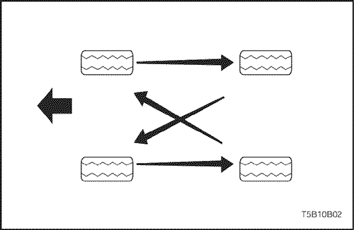
Check the tires for abnormal wear or damage. To equalize wear and obtain maximum tire life, rotate the tires. If irregular or premature wear exists, check the wheel alignment and check for damaged wheels. While the tires and wheels are removed, inspect the brakes. Refer to «Each Time The Oil Is Changed» in this section.
Scheduled Maintenance Charts
Engine
|
Maintenance |
Maintenance Interval |
||||||||
|
Item |
|||||||||
|
. |
Kilometers or time in months, whichever comes first |
||||||||
|
x 1,000 km |
15 |
30 |
45 |
60 |
75 |
90 |
105 |
120 |
|
|
x 1,000 miles |
10 |
20 |
30 |
40 |
50 |
60 |
70 |
80 |
|
|
Months |
12 |
24 |
36 |
48 |
60 |
72 |
84 |
96 |

|
Maintenance |
Maintenance Interval |
|||||||||
|
Item |
||||||||||
|
. |
Kilometers or time in months, whichever comes first |
|||||||||
|
x 1,000 km |
15 |
30 |
45 |
60 |
75 |
90 |
105 |
120 |
||
|
x 1,000 miles |
10 |
20 |
30 |
40 |
50 |
60 |
70 |
80 |
||
|
Months |
12 |
24 |
36 |
48 |
60 |
72 |
84 |
96 |
||
|
Drive belts |
||||||||||
|
(Alternator, |
I |
I |
I |
I |
||||||
|
power steering |
||||||||||
|
and A/C belt) |
||||||||||
|
Engine oil & |
||||||||||
|
engine oil filter |
R |
R |
R |
R |
R |
R |
R |
R |
||
|
(1) (3) |
||||||||||
|
Cooling system |
||||||||||
|
hose & |
I |
I |
I |
I |
I |
I |
I |
I |
||
|
connections |
||||||||||
|
Engine coolant (3) |
I |
I |
R |
I |
I |
R |
I |
I |
||
|
Fuel filter |
. |
. |
R |
. |
. |
R |
. |
. |
||
|
Fuel line and |
I |
I |
I |
I |
I |
I |
I |
I |
||
|
connections |
||||||||||
|
Air cleaner |
I |
I |
R |
I |
I |
R |
I |
I |
||
|
element (2) |
||||||||||
|
Spark plugs |
. |
I |
. |
R |
. |
I |
. |
R |
||
|
Spark plug wires |
Replace every 96,000 km(60,000 miles) |
|||||||||
|
EVAP canister, |
||||||||||
|
vapor lines & |
. |
. |
I |
. |
. |
I |
. |
. |
||
|
solenoid valve |
||||||||||
|
filter |
||||||||||
|
PCV system |
. |
I |
. |
I |
. |
I |
. |
I |
||
|
Timing belt |
. |
l |
. |
R |
. |
l |
. |
R |
||
Chart Symbols:
I -Inspect these items and their related parts. If necessary, correct, clean, replenish, adjust or replace.
R — Replace or change:
(1) Change the engine oil and oil filter every 7,500 km (5,000 miles) or 6months, whichever comes first, if the vehicle is operated under any of the following conditions:
o Short distance driving. o Extensive idling.
o Driving in dusty conditions.

(2)Inspect the air cleaner element every 7,500 km (5,000 miles) or 6 months if under dusty driving conditions. If necessary, correct, clean, or replace.
(3)Refer to «Recommended Fluids And Lubricants»
Chassis and Body
|
Maintenance Item |
Maintenance Interval |
||||||||
|
. |
Kilometers or time in months, whichever comes first |
||||||||
|
x 1,000 km |
15 |
30 |
45 |
60 |
75 |
90 |
105 |
120 |
|
|
x 1,000 miles |
9 |
18 |
27 |
36 |
45 |
54 |
63 |
72 |
|
|
Months |
12 |
24 |
36 |
48 |
60 |
72 |
84 |
96 |
|
|
Interior air filter |
R |
R |
R |
R |
R |
R |
R |
R |
|
|
(A/C) (6) |
|||||||||
|
Exhaust pipes & |
I |
I |
I |
I |
I |
I |
I |
I |
|
|
mountings |
|||||||||
|
Brake/Clutch |
I |
R |
I |
R |
I |
R |
I |
R |
|
|
fluid (1) (4) |
|||||||||
|
Front brake pads |
I |
I |
I |
I |
I |
I |
I |
I |
|
|
and discs(3) |
|||||||||
|
Rear brake pads |
|||||||||
|
discs or drums and |
I |
I |
I |
I |
I |
I |
I |
I |
|
|
linings (3) |
|||||||||
|
Parking brake |
I |
I |
I |
I |
I |
I |
I |
I |
|
|
Brake line and |
|||||||||
|
connections |
I |
I |
I |
I |
I |
I |
I |
I |
|
|
(Including booster) |
|||||||||
|
Manual Transaxle |
I |
I |
I |
I |
I |
I |
I |
I |
|
|
Oil *(1) |
|||||||||
|
Automatic |
|||||||||
|
transaxle fluid *(1) |
I |
I |
I |
I |
I |
I |
I |
I |
|
|
(5) |
|||||||||
|
Tighten chassis and |
|||||||||
|
underbody bolts |
I |
I |
I |
I |
I |
I |
I |
I |
|
|
and nuts |
|||||||||
|
Wheel alignment |
Inspect when abnormal condition is noted |
||||||||
|
(2) |
|||||||||
|
Steering wheel and |
I |
I |
I |
I |
I |
I |
I |
I |
|
|
linkage |
|||||||||
|
Power steering |
I |
I |
I |
I |
I |
I |
I |
I |
|
|
fluid & lines* (1) |
|||||||||
|
Drive shaft boots |
I |
I |
I |
I |
I |
I |
I |
I |
|
|
Seat belts, buckles |
I |
I |
I |
I |
I |
I |
I |
I |
|
|
and anchors |
|||||||||

|
Maintenance Item |
Maintenance Interval |
|||||||||
|
. |
Kilometers or time in months, whichever comes first |
|||||||||
|
x 1,000 km |
15 |
30 |
45 |
60 |
75 |
90 |
105 |
120 |
||
|
x 1,000 miles |
9 |
18 |
27 |
36 |
45 |
54 |
63 |
72 |
||
|
Months |
12 |
24 |
36 |
48 |
60 |
72 |
84 |
96 |
||
|
Lubricate locks, |
||||||||||
|
hinges and hood |
I |
I |
I |
I |
I |
I |
I |
I |
||
|
latch |
Chart Symbols:
I — Inspect and if necessary correct, clean, replenish, or adjust. R — Replace or change:
(1)Refer to Recommended Fluids And Lubricants.
(2)If necessary, rotate and balance wheels.
(3)More frequent maintenance is required if under severe conditions: short distance driving, extensive idling, frequent low-speed operaion in stop and go traffic, or driving in dusty conditions.
(4)Change the brake/clutch fluid every 15,000 km (10,000 miles), if the vehicle is mainly driven under the following severe conditions: driving in hilly or mountainous terrain, or towing a trailer/caravan frequently.
(5)Change automatic transaxle fluid every 60,000 Km (40,000 miles) if the vehicle is mainly driven under any of the following severe conditions:
oIn heavy city traffic where the outside temperature regularly reaches 32°C (90°F) or higher, or
o In hilly or mountainous terrain, or
o When doing frequent trailer towing, or
oUses such as found taxi, police or delivery service.
(6)More frequent maintenance is required if under dusty driving conditions.
OWNER INSPECTIONS AND SERVICES While Operating The Vehicle
Horn Operation
Blow the horn occasionally to make sure it works. Check all the button locations.
Brake System Operation
Be alert for abnormal sounds, increased brake pedal travel or repeated pulling to one side when braking. Also, if the brake warning light goes on, or flashes, something may be wrong with part of the brake system.
Exhaust System Operation
Be alert to any changes in the sound of the system or the smell of the fumes. These are signs that the system may be leaking or overheating. Have the system inspected and repaired immediately.
Tires, Wheels and Alignment Operation
Be alert to any vibration of the steering wheel or the seats at normal highway speeds. This may mean a wheel needs to be balanced. Also, a pull right or left on a straight, level road may show the need for a tire pressure adjustment or a wheel alignment.
Steering System Operation
Be alert to changes in the steering action. An inspection is needed when the steering wheel is hard to turn or has too much free play, or if unusual sounds are noticed when turning or parking.
Headlight Aim
Take note of the light pattern occasionally. Adjust the headlights if the beams seem improperly aimed.
At Each Fuel Fill
A fluid loss in any (except windshield washer) system may indicate a problem. Have the system inspected and repaired immediately.
Engine Oil Level
Check the oil level and add oil if necessary. The best time to check the engine oil level is when the oil is warm.
1.After stopping the engine, wait a few minutes for the oil to drain back to the oil pan.
2.Pull out the oil level indicator (dip stick).
3.Wipe it clean, and push the oil level indicator back down all the way.
4.Pull out the oil level indicator and look at the oil level on it.
5.Add oil, if needed, to keep the oil level above the MIN line and within the area labeled «Operating Range.» Avoid overfilling the engine, since this may cause engine damage.
6.Push the indicator all the way back down into the engine after taking the reading.
If you check the oil level when the oil is cold, do not run the engine first. The cold oil will not drain back to the pan fast enough to give a true oil level reading.
Engine Coolant Level and Condition
Check the coolant level in the coolant reservoir tank and add coolant if necessary. Inspect the coolant. Replace dirty or rusty coolant.
Windshield Washer Fluid Level
Check the washer fluid level in the reservoir. Add fluid if necessary.
At Least Monthly
Tire And Wheel Inspection and Pressure Check
Check the tires for abnormal wear or damage. Also check for damaged wheels. Check the tire pressure when the tires are cold (check the spare also, unless it is a stowaway). Maintain the recommended pressures that are on the tire placard that is in the glove box.
Light Operation
Check the operation of the license plate light, the headlights (including the high beams), the parking lights, the fog lights, the taillight, the brake lights, the turn signals, the backup lights and the hazard warning flasher.
Fluid Leak Check
Periodically inspect the surface beneath the vehicle for water, oil, fuel or other fluids, after the vehicle has been parked for a while. Water dripping from the air conditioning system after use is normal. If you notice fuel leaks or fumes, find the cause and correct it at once.
At Least Twice a Year
Power Steering System Reservoir Level
Check the power steering fluid level. Keep the power steering fluid at the proper level. Refer to Section 6A, Power Steering System.
Brake Master Cylinder Reservoir Level
Check the fluid and keep it at the proper level. A low fluid level can indicate worn disc brake pads which may need to be serviced. Check the breather hole in the reservoir cover to be free from dirt and check for an open passage.
Clutch Pedal Free Travel
Check clutch pedal free travel and adjust as necessary. Measure the distance from the center of the clutch pedal to the outer edge of the steering wheel with the clutch pedal not depressed. Then measure the distance from the center of the clutch pedal to the outer edge of the steering wheel with the clutch pedal fully depressed. The difference between the two values must be greater than 130 mm (5.19 inches).
Weather-Strip Lubrication
Apply a thin film silicone grease using a clean cloth.
Each Time The Oil is Changed Automatic Transaxle Fluid
Refer to «Transaxle Fluid Level Checking Procedure» in Section 5A, 4HP16 Automatic Transaxle.
Manual Transaxle
Check the oil level and add oil as required. Refer to Section 5B, Five-Speed Manual Transaxle.
Brake System Inspection
This inspection should be done when the wheels are removed for rotation. Inspect the lines and the hoses for proper hookup, binding, leaks, cracks, chafing, etc. Inspect the disc brake pads for wear. Inspect the rotors for surface condition. Inspect other brake parts, including the parking brake, etc., at the same time. Check the parking brake adjustment. Inspect the brakes more often if habit or conditions result in frequent braking.
Steering, Suspension and Front Drive Axle Boot and Seal Inspection
Inspect the front and rear suspension and the steering system for damaged, loose, or missing parts; signs of wear; or lack of lubrication. Inspect the power steering lines and the hoses for proper hookup, binding, leaks, cracks and chafing, etc. Clean and inspect the drive axle boot and seals for damage, tears, or leakage. Replace the seals if necessary.
Exhaust System Inspection
Inspect the complete system (including the catalytic converter, if equipped). Inspect the body near the exhaust system. Look for broken, damaged, missing, or out-of-position parts, as well as open seams, holes, loose connections, or other conditions which could cause heat buildup in the floor pan or could let exhaust fumes seep into the trunk or passenger compartment.
Throttle Linkage Inspection
Inspect the throttle linkage for interference or binding, damaged, or missing parts. Lubricate all linkage joints and throttle cable joints, the intermediate throttle shaft bearing, the return spring at throttle valve assembly, and the accelerator pedal sliding face with suitable grease. Check the throttle cable for free movement.
Engine Drive Belts
Inspect all belts for cracks, fraying, wear, and proper tension. Adjust or replace the belts as needed.
Hood Latch Operation
When opening the hood, note the operation of the secondary latch. It should keep the hood from opening all the way when the primary latch is released. The hood must close firmly.
At Least Annually
Lap and Shoulder Belts Condition and Operation
Inspect the belt system, including the webbing, the buckles, the latch plates, the retractor, the guide loops and the anchors.
Movable Head Restraint Operation
On vehicles with movable head restraints, the restraints must stay in the desired position.
Spare Tire and Jack Storage
Be alert to rattles in the rear of the vehicle. The spare tire, all the jacking equipment, and the tools must be securely stowed at all times. Oil the jack ratchet or the screw mechanism after each use.
Key Lock Service
Lubricate the key lock cylinder.
Body Lubrication Service
Lubricate all the body door hinges including the hood, the fuel door, the rear compartment hinges and the latches, the glove box and the console doors, and any folding seat hardware.
Transaxle Neutral Switch Operation on Automatic Transaxle
Caution : Adhere to the following precautions. Failure to do so can cause injuries and property damage.
Firmly apply the parking brake and the regular brakes.
Do not use the accelerator pedal.
Be ready to turn the ignition OFF if the vehicle starts.
On automatic transaxle vehicles, try to start the engine in each gear. The starter should crank only in P (PARK) and in N (NEUTRAL).
Parking Brake and Transaxle P (Park) Mechanism Operation
Caution : To reduce the risk of personal injury or property damage, be prepared to apply the regular brakes if the vehicle begins to move.
Park on a fairly steep hill with enough room for movement in the downhill direction. To check the parking brake, with the engine running and the transaxle in N (NEUTRAL), slowly remove foot pressure from the regular brake pedal (until only the parking brake is holding the vehicle).
To check the automatic transaxle P (Park) mechanism’s holding ability, release all brakes after shifting the transaxle to P (Park).
Underbody Flushing
Flushing the underbody will remove any corrosive materials used for ice and snow removal and dust control. At least every spring, clean the underbody. First, loosen the sediment packed in closed areas of the vehicle. Then flush the underbody with plain water.
Engine Cooling System
Inspect the coolant and freeze protection fluid. If the fluid is dirty or rusty, drain, flush and refill the engine cooling system with new coolant. Keep the coolant at the proper mixture in order to ensure proper freeze protection, corrosion protection and engine operating temperature. Inspect the hoses. Replace the cracked, swollen, or deteriorated hoses. Tighten the clamps. Clean the outside of the radiator and the air conditioning condenser. Wash the

filler cap and the neck. Pressure test the cooling system and the cap in order to help ensure proper operation.
Recommended Fluids and Lubricants
|
Usage |
Capacity |
Fluid/Lubricant |
|||
|
Engine Oil |
4.0L (4.2 qt) |
API SL (ILSAC GF-III) grade |
|||
|
SAE 10W-30 cold area: SAE 5W-30 |
|||||
|
Engine Coolant |
7.5L (7.9 qt) |
Mixture of water and good quality silicate |
|||
|
base antifreeze (year-round coolant) |
|||||
|
Brake Fluid and Clutch |
0.5L (0.5 qt) |
DOT-3 or DOT-4 |
|||
|
Fluid |
|||||
|
Power Steering System |
1.1L (1.2 qt) |
DEXRON®-III, DEXRON®II-D |
|||
|
Fluid |
|||||
|
Automatic Transaxle |
6.9 ± 0.2L (7.3 ± 0.2 |
ESSO LT 71141 or TOTAL ATF H50235 |
|||
|
qt) |
|||||
|
Manual Transaxle |
1.8L (2 qt) |
SAE80 |
|||
|
Extremely cold area: SAE 75W |
|||||
|
Manual Transaxle Shift |
As needed |
Multipurpose-type grease meeting |
|||
|
Linkage |
requirements NLGI No. 1 or 2 |
||||
|
Key Lock Cylinders |
As needed |
Silicone lubricant |
|||
|
Automatic Transaxle Shift |
As needed |
Engine oil |
|||
|
Linkage |
|||||
|
Clutch Linkage Pivot Points |
As needed |
Engine oil |
|||
|
Floor Shift Linkage Points |
As needed |
Engine oil |
|||
|
Hood Latch Assembly |
As needed |
||||
|
1. |
Pivots and Spring |
1. |
Engine oil |
||
|
Anchor |
2. |
Multipurpose-type grease meeting |
|||
|
2. |
Release Pawl |
requirements NLGI No. 1 or 2 |
|||
|
Hood and door hinges |
As needed |
Engine oil |
|||
|
Fuel door hinge |
|||||
|
Rear compartment lid |
|||||
|
hinges |
|||||
|
Weatherstripping |
As needed |
Silicone grease |
GENERAL DESCRIPTION AND SYSTEM OPERATION
General Repair Instructions
If a floor jack is used, the following precautions are recommended:
Park the vehicle on level ground, “block” the front or rear wheels, set the jack against the frame, raise the vehicle and support it with chassis stands and then perform the service operation.
Before performing the service operation, disconnect the negative battery cable in order to reduce the chance of cable damage and burning due to short-circuiting.
Use a cover on the body, the seats and the floor to protect them against damage and contamination.
Handle brake fluid and antifreeze solution with care as they can cause paint damage.
The use of proper tools, and the recommended essential and available tools where specified, are important for efficient and reliable performance of the service repairs.
Use genuine DAEWOO parts.
Discard used cotter pins, gaskets, O-rings, oil seals, lock washers and self-locking nuts. Prepare new ones for installation. Normal function of these parts cannot be maintained if these parts are reused.
Keep the disassembled parts neatly in groups to facilitate proper and smooth reassembly.
Keep attaching bolts and nuts separated, as they vary in hardness and design depending on the position of the installation.
Clean the parts before inspection or reassembly.
Also clean the oil parts, etc. Use compressed air to make certain they are free of restrictions.
Lubricate rotating and sliding faces of parts with oil or grease before installation.
When necessary, use a sealer on gaskets to prevent leakage.
Carefully observe all specifications for bolt and nut torques.
When service operation is complete, make a final check to be sure service was done properly and the problem was corrected.
GENERAL DESCRIPTION
Vehicle and Component Identification
Passenger Car Vehicle Identification Number

VIN Plate Location
The vehicle identification number (VIN) plate is attached to the top of the front panel support.

VIN Plate
1.Manufacturer’s Name
2.NTA Number or WVTA Number

3.Vehicle Identification Number
4.Gross Vehicle Weight
5.Combination Weight
6.Front Axle Weight
7.Rear Axle Weight
Engraved VIN Location
The vehicle identification number (VIN) is engraved in the top right side of the bulkhead.
Engine Number Location

The engine number is stamped on the cylinder block under the No. 4 exhaust manifold of the engine.
Engine Number

Body Identification Number Plate

1.P/O Number
2.Check Digit
3.Drive
4.Body Type
5.Production Month
6.Production Date
7.Sequential Number
8.Trunk Lid
9.Exterior Color
10.Export Country
11.Car Type
Body Identification Number Plate Location

The body identification number plate is attached to the top of the front panel support.
Manual Transmission Identification Number Plate

1.Identification Code
2.Sequential Number
|
Identification |
Engine |
Gear Ratio |
|
|
Code |
|||
|
FD |
2.0L DOHC |
4.176 |
|
|
MEDIUM |
|||
Manual Transaxle Identification Number Plate Location

The manual transaxle identification number is attached to the top of the transmission case near the engine.
Automatic Transmission Identification Number Plate (ZF 4HP 16)

1.Part Number
2.Serial Number
3.Model Code
4.Manufactured Nation and Company
|
Part Code |
Engine |
|
BD |
2.0L DOHC |
Automatic Transaxle Identification Number Plate Location

Vehicle Lifting Procedures
Notice : To raise the vehicle, place the lifting equipment only at the points indicated. Failure to use these precise positions may result in permanent body deformation.
Notice : Many dealer service facilities and service stations are equipped with automotive hoists that bear upon some parts of the frame to lift the vehicle. If any other hoist method is used, use special care to avoid damaging the fuel thank, the filler neck, the exhaust system, or the underbody.
Vehicle Lifting Points

Vehicle Lifting Points

© Copyright General Motors Daewoo Europe. All rights reserved
 Evanda

SECTION 1A
GENERAL ENGINE INFORMATION
DIAGNOSIS
Compression Test
Important : Disconnect the Crankshaft Position Sensor (CPS) connector to disable the fuel and the ignition systems.
Test the compression pressure for each cylinder. Low compression pressure may be the fault of the valves or the pistons. The following conditions should be considered when you check the cylinder compression:
The engine should be at normal operating temperature.
The throttle must be wide open.
All the spark plugs should be removed.
The battery must be at or near full charge.
1.Place approximately three squirts of oil from a plunger type oiler into each spark plug port.
2.Insert the engine compression gauge into each spark plug port.
3.Crank test each cylinder with four to five compression strokes using the starter motor.
4.The lowest reading should not be less than 70% of the highest reading. The compression gauge reading should not be less than 689 kPa (100 psi) for any of the cylinders.
5.Examine the gauge readings obtained after the four «puffs» per cylinder are obtained from cranking the starter motor. The readings are explained in the following descriptions:
Normal Condition — Compression builds up quickly and evenly to the specified compression on each cylinder.
Piston Rings Faulty — Compression is low on the first stroke and tends to build up on following strokes, but the compression pressure does not reach normal. The compression pressure improves considerably with the addition of oil into the cylinder.
Valves Faulty — Low compression pressure on the first stroke. The compression pressure does not tend to build up on the following

strokes. The compression pressure does not improve much with the addition of oil into the cylinder.
Oil Pressure Test
|
Step |
Action |
Value(s) |
Yes |
No |
|
|
1 |
Is low or no oil pressure indicated? |
— |
Go toStep 2 |
System OK |
|
|
2 |
Check the oil level in the crankcase. |
— |
|||
|
Is the level low? |
Go toStep 3 |
Go toStep 4 |
|||
|
Add oil so that the oil level is up to the full |
|||||
|
3 |
mark on the indicator. |
— |
|||
|
Is the repair complete? |
Go toStep 1 |
— |
|||
|
4 |
Check the idle speed. |
850 rpm |
|||
|
Is the idle speed below the value specified? |
Go toStep 5 |
Go toStep 6 |
|||
|
5 |
Increase the idle speed. |
— |
|||
|
Is the speed increased? |
Go toStep 1 |
— |
|||
|
Inspect the oil pressure switch. |
|||||
|
6 |
Is the oil pressure switch incorrect or |
— |
|||
|
malfunctioning? |
Go toStep 7 |
Go toStep 8 |
|||
|
7 |
Install a new oil pressure switch. |
— |
|||
|
Is the repair complete? |
Go toStep 1 |
— |
|||
|
Inspect the oil pressure gauge on the cluster. |
|||||
|
8 |
Is the oil pressure gauge incorrect or |
— |
|||
|
malfunctioning? |
Go toStep 9 |
Go toStep 10 |
|||
|
9 |
Install a new oil pressure gauge. |
— |
|||
|
Is the repair complete? |
Go toStep 1 |
— |
|||
|
Inspect the engine oil. |
|||||
|
10 |
Is the engine oil in the crankcase diluted or of |
— |
|||
|
the improper viscosity? |
Go toStep 11 |
Go toStep 12 |
|||
|
Install new engine oil of the proper viscosity |
|||||
|
11 |
for the expected temperatures. |
— |
|||
|
Is the repair complete? |
Go toStep 1 |
— |
|||
|
12 |
Inspect the oil pump. |
— |
|||
|
Is the pump worn or dirty? |
Go toStep 13 |
Go toStep 14 |
|||
|
13 |
Replace the oil pump. |
— |
|||
|
Is the repair complete? |
Go toStep 1 |
— |
|||
|
14 |
Inspect the oil filter. |
— |
|||
|
Is the oil filter plugged? |
Go toStep 15 |
Go toStep 16 |
|||
|
15 |
Install a new oil filter. |
— |
|||
|
Is the repair complete? |
Go toStep 1 |
— |
|||
|
16 |
Inspect the oil pickup screen. |
— |
|||
|
Is the oil pickup screen loose or plugged? |
Go toStep 17 |
Go toStep 18 |
|||
|
17 |
Tighten or replace the oil pickup screen as |
— |
Go toStep 1 |
— |

|
Step |
Action |
Value(s) |
Yes |
No |
|
|
necessary. |
|||||
|
Is the repair complete? |
|||||
|
18 |
Inspect the oil pickup tube. |
— |
|||
|
Are there any holes in the oil pickup tube? |
Go toStep 19 |
Go toStep 20 |
|||
|
19 |
Replace the oil pickup tube. |
— |
|||
|
Is the repair complete? |
Go toStep 1 |
— |
|||
|
Inspect the bearing clearances. |
Crankshaft |
||||
|
Are the bearing clearances more than the |
0.040 mm |
||||
|
values specified? |
(0.0016 in.) |
||||
|
20 |
Connecting |
||||
|
Rod |
|||||
|
0.063 mm |
|||||
|
(0.0025 in.) |
Go toStep 21 |
Go toStep 22 |
|||
|
21 |
Replace the bearing, if necessary. |
— |
|||
|
Is the repair complete? |
Go toStep 1 |
— |
|||
|
Inspect the oil galleries. |
|||||
|
22 |
Are the oil galleries cracked, porous, or |
— |
|||
|
plugged? |
Go toStep 23 |
Go toStep 24 |
|||
|
23 |
Repair or replace the engine block. |
— |
|||
|
Is the repair complete? |
Go toStep 1 |
— |
|||
|
Inspect the gallery plugs. |
|||||
|
24 |
Are any of the gallery plugs missing or |
— |
|||
|
installed properly? |
Go toStep 25 |
Go toStep 26 |
|||
|
25 |
Install the plugs or repair as necessary. |
— |
|||
|
Is the repair complete? |
Go toStep 1 |
— |
|||
|
Inspect the camshaft. |
|||||
|
26 |
Is the camshaft worn or is there evidence of |
— |
|||
|
poor machining? |
Go toStep 27 |
System OK |
|||
|
27 |
Replace the camshaft. |
— |
|||
|
Is the repair complete? |
Go toStep 1 |
— |
|||
Oil Leak Diagnosis
Most fluid oil leaks are easily located and repaired by visually finding the leak and replacing or repairing the necessary parts. On some occasions a fluid leak may be difficult to locate or repair. The following procedures may help you in locating and repairing most leaks:
Finding the Leak
1.Identify the fluid. Determine whether it is engine oil, automatic transmission fluid, power steering fluid, etc.
2.Identify where the fluid is leaking from.
1.After running the vehicle at normal operating temperature, park the vehicle over a large sheet of paper.
2.Wait a few minutes.
3.You should be able to find the approximate location of the leak by the drippings on the paper.
3.Visually check around the suspected component. Check around all the gasket mating surfaces for leaks. A mirror is useful for finding leaks in areas that are hard to reach.
4.If the leak still cannot be found, it may be necessary to clean the suspected area with a degreaser, steam, or spray solvent.
1.Clean the area well.
2.Dry the area.
3.Operate the vehicle for several miles at normal operating temperature and varying speeds.
4.After operating the vehicle, visually check the suspected component.
5.If the leak is not located, try using the powder or black light and dye method.
Powder Method
1.Clean the suspected area.
2.Apply an aerosol-type powder (such as foot powder) to the suspected area.
3.Operate the vehicle under normal operating conditions.
4.Visually inspect the suspected component. You should be able to trace the leak path over the white powder surface to the source.
Black Light and Dye Method
A dye and light kit is available for finding leaks. Refer to the manufacturer’s directions when using the kit.
1.Pour the specified amount of dye into the engine oil fill tube.
2.Operate the vehicle under normal operating conditions, as directed in the kit.
3.Direct the light toward the suspected area. The dyed fluid will appear as a yellow path leading to the source.
Repairing the Leak
Once the origin of the leak has been pinpointed and traced back to its source, the cause of the leak must be determined for it to be repaired properly. If a gasket is replaced, but the sealing flange is bent, the new gasket will not

repair the leak. The bent flange must be repaired also. Before attempting to repair a leak, check for the following conditions and correct them as they may cause a leak:
Gaskets
The fluid level/pressure is too high.
The crankcase ventilation system is malfunctioning.
The fasteners are tightened improperly or the threads are dirty or damaged.
The flanges or the sealing surface is warped.
There are scratches, burrs or other damage to the sealing surface.
The gasket is damaged or worn.
There is cracking or porosity of the component.
An improper seal was used (where applicable).
Seals
The fluid level/pressure is too high.
The crank case ventilation system is malfunctioning.
The seal bore is damaged (scratched, burred or nicked).
The seal is damaged or worn.
Improper installation is evident.
There are cracks in the component.
The shaft surface is scratched, nicked or damaged.
A loose or worn bearing is causing excess seal wear.
Knock Diagnosis
Definition for Knock
Engine knock refers to various types of engine noise. Heavy knock is usually very loud and the result of broken or excessively worn internal engine components. Light knock is a noticeable noise, but not as loud. Light knock can be caused by worn internal engine components. Loose or broken external engine components can also cause heavy or light knock.
Engine Knocks Cold and Continues for Two-Three Minutes and/or Knock Increases with Engine Torque
|
Step |
Action |
Value(s) |
Yes |
No |
|
|
Does the engine knock when it is cold and |
|||||
|
1 |
continue for two to three minutes or does the |
— |
|||
|
knock increase with torque? |
Go toStep 2 |
System OK |
|||
|
2 |
Inspect the flywheel. |
— |
|||
|
Is the flywheel contacting the splash shield? |
Go toStep 3 |
Go toStep 4 |
|||
|
3 |
Reposition the splash shield. |
— |
Go toStep 1 |
— |

|
Step |
Action |
Value(s) |
Yes |
No |
|
|
Is the repair complete? |
|||||
|
Inspect the balancer and the drive pulleys. |
|||||
|
4 |
Is either the balancer or the drive pulleys loose |
— |
|||
|
or broken? |
Go toStep 5 |
Go toStep 6 |
|||
|
Tighten or replace the balancer or the drive |
|||||
|
5 |
pulleys. |
— |
|||
|
Is the repair complete? |
Go toStep 1 |
— |
|||
|
6 |
Inspect the piston-to-bore clearance. |
0.030 mm |
|||
|
Is the clearance more than the value specified? |
(0.001 in.) |
Go toStep 7 |
Go toStep 8 |
||
|
1. Rebore the cylinder and hone to size. |
|||||
|
7 |
2. Replace the piston. |
— |
|||
|
Is the repair complete?* |
Go toStep 1 |
— |
|||
|
8 |
Inspect the connecting rod. |
— |
|||
|
Is the connecting rod bent? |
Go toStep 9 |
System OK |
|||
|
9 |
Replace the connecting rod. |
— |
|||
|
Is the repair complete? |
Go toStep 1 |
— |
|||
* Cold engine piston knock usually disappears when the cylinder is grounded out. Cold engine piston knock, which disappears in about 1.5 minutes, is considered acceptable.
Heavy Knock Hot with Torque Applied
|
Step |
Action |
Value(s) |
Yes |
No |
|
|
1 |
Is there a heavy knock when the engine is hot |
— |
|||
|
and torque is applied? |
Go toStep 2 |
System OK |
|||
|
2 |
Inspect the balancer and the pulley hub. |
— |
|||
|
Is the balancer or the pulley hub broken? |
Go toStep 3 |
Go toStep 4 |
|||
|
3 |
Replace the broken balancer or the pulley hub. |
— |
|||
|
Is the repair complete? |
Go toStep 1 |
— |
|||
|
4 |
Inspect the torque converter bolts. |
60 N•m |
|||
|
Are the bolts tightened to value specified? |
(44 lb-ft) |
Go toStep 5 |
Go toStep 6 |
||
|
5 |
Tighten the torque converter bolts. |
— |
|||
|
Is the repair complete? |
Go toStep 1 |
— |
|||
|
6 |
Inspect the accessory belts. |
— |
|||
|
Are the belts too tight or nicked? |
Go toStep 7 |
Go toStep 8 |
|||
|
Replace and/or tension the belts to |
|||||
|
7 |
specifications, as necessary. |
Go to |
|||
|
Is the repair complete? |
Go toStep 1 |
Go to |
|||
|
8 |
Inspect the exhaust system. |
Go to |
|||
|
Is the system grounded? |
Go toStep 9 |
Go toStep 10 |
|||
|
9 |
Reposition the system, as necessary. |
— |
|||
|
Is the repair complete? |
Go toStep 1 |
— |
|||

|
Step |
Action |
Value(s) |
Yes |
No |
|
|
10 |
Inspect the flywheel. |
— |
|||
|
Is the flywheel cracked? |
Go toStep 11 |
Go toStep 12 |
|||
|
11 |
Replace the flywheel. |
— |
|||
|
Is the repair complete? |
Go toStep 1 |
— |
|||
|
12 |
Inspect the main bearing clearance. |
0.040 mm |
|||
|
Is the clearance more than the value specified? |
(0.0016 in.) |
Go toStep 13 |
Go toStep 14 |
||
|
13 |
Replace the main bearings as necessary. |
— |
|||
|
Is the repair complete? |
Go toStep 1 |
— |
|||
|
14 |
Inspect the rod bearing clearance. |
0.063 mm |
|||
|
Is the clearance more than the specified value? |
(0.0025 in.) |
Go toStep 15 |
System OK |
||
|
15 |
Replace the rod bearings as necessary. |
— |
|||
|
Is the repair complete? |
Go toStep 1 |
— |
|||
|
Light Knock Hot |
|||||
|
Step |
Action |
Value(s) |
Yes |
No |
|
|
1 |
Is there a light knock when the engine is hot? |
— |
Go toStep 2 |
System OK |
|
|
2 |
Is detonation or spark knock evident? |
— |
Go toStep 3 |
Go toStep 4 |
|
|
3 |
Check the engine timing and the fuel quality. |
— |
|||
|
Was the problem found? |
Go toStep 1 |
— |
|||
|
4 |
Inspect the torque converter bolts. |
— |
|||
|
Are the bolts loose? |
Go toStep 5 |
Go toStep 6 |
|||
|
5 |
Tighten the torque converter bolts. |
— |
|||
|
Is the repair complete? |
Go toStep 1 |
— |
|||
|
6 |
Inspect the manifold. |
— |
|||
|
Is there an exhaust leak at the manifold? |
Go toStep 7 |
Go toStep 8 |
|||
|
7 |
Tighten the bolts or replace the gasket. |
— |
|||
|
Is the repair complete? |
Go toStep 1 |
— |
|||
|
Check the rod bearing clearance. |
0.019-0.063 |
||||
|
8 |
Is the clearance within the value specified? |
mm |
|||
|
(0.0007- |
|||||
|
0.0024 in.) |
Go toStep 9 |
System OK |
|||
|
9 |
Replace the rod bearings, as necessary. |
— |
|||
|
Is the repair complete? |
Go toStep 1 |
— |
|||
|
Knocks During Initial Start-Up But Lasts Only a Few Seconds |
|||||
|
Step |
Action |
Value(s) |
Yes |
No |
|
|
1 |
Does the engine knock during initial start-up |
— |
|||
|
but last only a few seconds? |
Go toStep 2 |
System OK |
|||
|
Check the engine oil. |
|||||
|
2 |
Is the proper viscosity oil used in the |
— |
|||
|
crankcase? |
Go toStep 4 |
Go toStep 3 |
|||
|
3 |
Install oil of the proper viscosity for the |
— |
Go toStep 1 |
— |

|
Step |
Action |
Value(s) |
Yes |
No |
|
|
expected seasonal temperatures. |
|||||
|
Is the repair complete? |
|||||
|
Inspect the hydraulic lifters. |
|||||
|
4 |
Is there evidence of hydraulic lifter bleed- |
— |
|||
|
down? |
Go toStep 5 |
Go toStep 6 |
|||
|
5 |
Clean, test and replace the lifters as necessary. |
— |
|||
|
Is the repair complete?* |
Go toStep 1 |
— |
|||
|
6 |
Inspect the crankshaft end clearance. |
0.302 mm |
|||
|
Is the clearance more than specified value? |
(0.012 in.) |
Go toStep 7 |
Go toStep 8 |
||
|
7 |
Replace the crankshaft thrust bearing. |
— |
|||
|
Is the repair complete? |
Go toStep 1 |
— |
|||
|
8 |
Inspect the front main bearing clearance. |
0.040 mm |
|||
|
Is the clearance more than the value specified? |
(0.0016 in.) |
Go toStep 9 |
System OK |
||
|
Replace the worn parts of the front main |
|||||
|
9 |
bearing. |
— |
|||
|
Is the repair complete? |
Go toStep 1 |
— |
|||
* When the engine is stopped, some valves will be open. Spring pressure against the lifters will tend to bleed the lifter down. Attempts to repair this should be made only if the problem is consistent.
An engine that is operated for only short periods between start-ups may have lifter noise that lasts for a few minutes. This is a normal condition.
Knocks at Idle Hot
|
Step |
Action |
Value(s) |
Yes |
No |
|
|
1 |
Does the engine knock at idle when hot? |
— |
Go toStep 2 |
System OK |
|
|
2 |
Inspect the drive belts. |
— |
|||
|
Are the belts loose or worn? |
Go toStep 3 |
Go toStep 4 |
|||
|
3 |
Tension or replace the belts, as necessary. |
— |
|||
|
Is the repair complete? |
Go toStep 1 |
— |
|||
|
Inspect the A/C compressor and the generator. |
|||||
|
4 |
Is either the compressor or the generator |
— |
|||
|
faulty? |
Go toStep 5 |
Go toStep 6 |
|||
|
Replace the faulty A/C compressor or the |
|||||
|
5 |
generator. |
— |
|||
|
Is the repair complete? |
Go toStep 1 |
— |
|||
|
6 |
Inspect the valve train. |
— |
|||
|
Are valve train components faulty? |
Go toStep 7 |
Go toStep 8 |
|||
|
7 |
Replace faulty valve train components. |
— |
|||
|
Is the repair complete? |
Go toStep 1 |
— |
|||
|
Check the engine oil. |
|||||
|
8 |
Is the proper viscosity oil used in the |
— |
|||
|
crankcase? |
Go toStep 10 |
Go toStep 9 |
|||

|
Step |
Action |
Value(s) |
Yes |
No |
|||||
|
Install oil of the proper viscosity for the |
|||||||||
|
9 |
expected seasonal temperatures. |
— |
|||||||
|
Is the repair complete? |
Go toStep 1 |
— |
|||||||
|
10 |
Inspect the piston pin clearance. |
0.014 mm |
|||||||
|
Is the clearance more than the specified value? |
(0.0005 in.) |
Go toStep 11 |
Go toStep 12 |
||||||
|
11 |
Replace the piston and the pin. |
— |
|||||||
|
Is the repair complete? |
Go toStep 1 |
— |
|||||||
|
12 |
Check the connecting rod alignment. |
— |
|||||||
|
Is the alignment faulty? |
Go toStep 13 |
Go toStep 14 |
|||||||
|
13 |
Check and replace rods as necessary. |
— |
|||||||
|
Is the repair complete? |
Go toStep 1 |
— |
|||||||
|
14 |
Inspect the piston-to-bore clearance. |
0.03 mm |
|||||||
|
Is the clearance within the specified value? |
(0.0012 in.) |
Go toStep 16 |
Go toStep 15 |
||||||
|
15 |
Hone the bore and fit a new piston. |
— |
|||||||
|
Is the repair complete? |
Go toStep 1 |
— |
|||||||
|
16 |
Inspect the crankshaft balancer. |
— |
|||||||
|
Is the balancer loose? |
Go toStep 17 |
Go toStep 18 |
|||||||
|
17 |
Torque or replace worn parts. |
— |
|||||||
|
Is the repair complete? |
Go toStep 1 |
— |
|||||||
|
Check the piston pin offset. |
0.8 mm |
||||||||
|
18 |
Is the offset at the value specified? |
(0.031 in.) |
|||||||
|
Toward |
|||||||||
|
Thrust Side |
Go toStep 19 |
System OK |
|||||||
|
19 |
Install the correct piston. |
— |
|||||||
|
Is the repair complete? |
Go toStep 1 |
— |
|||||||
|
Noise Diagnosis |
|||||||||
|
Main Bearing Noise |
|||||||||
|
Step |
Action |
Value(s) |
Yes |
No |
|||||
|
1 |
Are dull thuds or knocks heard with every |
— |
|||||||
|
engine revolution? |
Go to Step 2 |
System OK |
|||||||
|
Check the oil pump pressure. |
Go to Oil |
||||||||
|
2 |
Is the oil pump pressure low? |
— |
Pressure |
||||||
|
Test |
Go toStep 3 |
||||||||
|
Inspect the crankshaft end play. |
0.070~0.302mm |
Go |
|||||||
|
3 |
Is there excessive crankshaft end play? |
toCrankshaft |
|||||||
|
(0.0027~0.0119 |
Replacement |
||||||||
|
in.) |
|||||||||
|
Procedure |
Go toStep 4 |
||||||||
|
Inspect the crankshaft journals. |
Go |
||||||||
|
4 |
Are the crankshaft journals out-of-round? |
— |
toCrankshaft |
||||||
|
Replacement |
|||||||||
|
Procedure |
Go toStep 5 |

|
Step |
Action |
Value(s) |
Yes |
No |
||||
|
Inspect the belt tension. |
Go to Timing |
|||||||
|
5 |
Is there excessive belt tension? |
— |
Belt |
|||||
|
Replacement |
||||||||
|
Procedure |
Go toStep 6 |
|||||||
|
Inspect the crankshaft pulley. |
Go |
|||||||
|
6 |
Is the crankshaft pulley loose? |
— |
toCrankshaft |
|||||
|
Replacement |
||||||||
|
Procedure |
System OK |
|||||||
|
Connecting Rod Bearing Noise Symptom |
||||||||
|
Step |
Action |
Value(s) |
Yes |
No |
||||
|
1 |
Is a knock noise heard under all engine |
— |
||||||
|
speeds? |
Go to Step 2 |
System OK |
||||||
|
Inspect the crankshaft connecting rod journal. |
Go |
|||||||
|
2 |
Is the crankshaft connecting rod journal worn? |
— |
toCrankshaft |
|||||
|
Replacement |
||||||||
|
Procedure |
Go to Step 3 |
|||||||
|
3 |
Check the oil pump pressure. |
— |
Go to Oil |
|||||
|
Is the oil pump pressure low? |
Pressure Test |
Go to Step 4 |
||||||
|
Inspect the crankshaft connecting rod journals. |
Go |
|||||||
|
4 |
Are the journals out-of-round? |
— |
toCrankshaft |
|||||
|
Replacement |
||||||||
|
Procedure |
Go to Step 5 |
|||||||
|
Inspect the connecting rods. |
Go to Pistons |
|||||||
|
5 |
Is there a misaligned connecting rod? |
— |
and Rods |
|||||
|
Replacement |
||||||||
|
Procedure |
Go to Step 6 |
|||||||
|
Inspect the connecting rod bolts. |
Go to Pistons |
|||||||
|
6 |
Are the connecting rod bolts torqued properly? |
— |
and Rods |
|||||
|
Replacement |
||||||||
|
System OK |
Procedure |
|||||||
|
Piston Noises |
||||||||
|
Step |
Action |
Value(s) |
Yes |
No |
||||
|
Are any of the following noises heard: a sharp |
||||||||
|
1 |
double knock when the engine is idling, a light |
— |
||||||
|
ticking with no load on the engine, or a |
||||||||
|
«slapping» noise when the engine is cold? |
Go to Step 2 |
System OK |
||||||
|
Inspect the piston pin and the bushing. |
Go to Pistons |
|||||||
|
2 |
Is the piston pin or the bushing worn or loose? |
— |
and Rods |
|||||
|
Replacement |
||||||||
|
Procedure |
Go toStep 3 |
|||||||
|
3 |
Inspect the piston. |
— |
Go to Pistons |
|||||
|
Is the piston broken or cracked? |
and Rods |
Go toStep 4 |
||||||

|
Step |
Action |
Value(s) |
Yes |
No |
|
Replacement |
||||
|
Procedure |
||||
|
Inspect the connecting rods. |
Go to Pistons |
|||
|
4 |
Is there a misaligned connecting rod? |
— |
and Rods |
|
|
Replacement |
||||
|
Procedure |
Go toStep 5 |
|||
|
Inspect the piston position. |
Go to Pistons |
|||
|
5 |
Is the piston 180° out of position? |
— |
and Rods |
|
|
Replacement |
||||
|
Procedure |
System OK |
|||
|
Valve Mechanism or Valve Train Noises |
||||
|
Step |
Action |
Value(s) |
Yes |
No |
|
1 |
Is a light tapping sound heard from the engine? |
— |
Go to Step 2 |
System OK |
|
Inspect the valve springs. |
Go |
|||
|
Are the springs weak or broken? |
toCylinder |
|||
|
Head and |
||||
|
2 |
— |
Valve Train |
||
|
Components |
||||
|
Replacement |
||||
|
Procedure |
Go toStep 3 |
|||
|
Inspect the valves. |
Go |
|||
|
Are the valves sticking or warped? |
toCylinder |
|||
|
Head and |
||||
|
3 |
— |
Valve Train |
||
|
Components |
||||
|
Replacement |
||||
|
Procedure |
Go toStep 4 |
|||
|
Inspect the valve lifters. |
Go |
|||
|
Are the valve lifters dirty, stuck or worn? |
toCylinder |
|||
|
Head and |
||||
|
4 |
— |
Valve Train |
||
|
Components |
||||
|
Replacement |
||||
|
Procedure |
Go toStep 5 |
|||
|
Inspect the camshaft lobes. |
Go |
|||
|
5 |
Are the camshaft lobes damaged or improperly |
— |
toCamshaft |
|
|
machined? |
Replacement |
|||
|
Procedure |
Go toStep 6 |
|||
|
Check the oil supply to the valve train. |
Go |
|||
|
Is the oil supply insufficient or poor? |
toCylinder |
|||
|
6 |
— |
Head and |
||
|
Valve Train |
||||
|
Components |
Go toStep 7 |

|
Step |
Action |
Value(s) |
Yes |
No |
|
Replacement |
||||
|
Procedure |
||||
|
Inspect the valve guides. |
Go |
|||
|
Are the valve guides worn? |
toCylinder |
|||
|
Head and |
||||
|
7 |
— |
Valve Train |
||
|
Components |
||||
|
Replacement |
||||
|
Procedure |
Go toStep 8 |
|||
|
Inspect the valve spring seat. |
Go |
|||
|
Is the valve spring seat incorrect? |
toCylinder |
|||
|
Head and |
||||
|
8 |
— |
Valve Train |
||
|
Components |
||||
|
Replacement |
||||
|
Procedure |
System OK |
|||
GENERAL INFORMATION
Cleanliness and Care
An automobile engine is a combination of many machined, honed, polished and lapped surfaces with tolerances that are measured in the ten-thousandths of an inch. When any internal engine parts are serviced, care and cleanliness are important. A liberal coating of engine oil should be applied to friction areas during assembly, to protect and lubricate the surfaces on initial operation. Proper cleaning and protection of machined surfaces and friction areas is part of the repair procedure. This is considered standard shop practice, even if not specifically stated.
Whenever valve train components are removed for service, they should be kept in order. They should be installed in the same locations, and with the same mating surfaces, as when they were removed.
Battery cables should be disconnected before any major work is performed on the engine. Failure to disconnect the cables may result in damage to wire harness or other electrical parts.
On-Engine Service
Caution : Disconnect the negative battery cable before removing or installing any electrical unit, or when a tool or equipment could easily come in contact with exposed electrical terminals. Disconnecting this cable will help prevent personal injury and damage to the vehicle. The ignition must also be in LOCK unless otherwise noted.
Notice : Any time the air cleaner is removed, the intake opening should be covered. This will protect against the accidental entrance of foreign

material, which could follow the intake passage into the cylinder, and cause extensive damage when the engine is started.
© Copyright General Motors Daewoo Europe. All rights reserved
Evanda
SECTION 1C
DOHC ENGINE MECHANICAL
Caution : Disconnect the negative battery cable before removing or installing any electrical unit or when a tool or equipment could easily come in contact with exposed electrical terminals. Disconnecting this cable will help prevent personal injury and damage to the vehicle. The ignition must also be in LOCK unless otherwise noted.
|
SPECIFICATIONS |
|
|
Engine Specifications |
|
|
Application |
2.0L DOHC |
|
General Data: |
|
|
Engine Type |
4 Cylinder (In-Line) |
|
Displacement |
1,998 cm³ (121 in³) |
|
Bore Stroke |
86 x 86 mm (3.38 in x 3.38 in.) |
|
Compression Ratio |
9.6 :1 |
|
Firing Order |
1-3-4-2 |
|
Cylinder Bore: |
|
|
Diameter |
85.975~86.025 mm (3.384~3.386 in.) |
|
Out of Round (Maximum) |
0.013 mm (0.0005 in.) |
|
Cylinder Bore Taper (Maximum) |
0.013 mm (0.0005 in.) |
|
Piston Protrusion |
0.5 mm Max (0.019 in.) |
|
Oversize (Measure Replacement Piston before |
Available in 0.50 mm to suit bore (0.019 in.) |

|
Application |
2.0L DOHC |
|
|
Re-boring) |
||
|
Service Replacement Standard Bore |
4 Piston, Pin, and Ring Assemblies Available |
|
|
Block Face Distortion |
0.01 mm Max (0.00039 in.) |
|
|
Piston: |
||
|
Diameter |
85.955~86.485 mm (3.384~3.404 in.) |
|
|
Clearance to Bore |
0.010~0.030 mm (0.00039~0.0020 in.) |
|
|
Piston Protrusion |
0.5 mm Max (0.019 in.) |
|
|
Piston Taper |
0.013 mm (0.0005 in.) |
|
|
Piston Rings: |
||
|
Ring, End Gap, Top Compression |
0.2~0.35 mm (0.007~0.013 in.) |
|
|
Ring, End Gap, Second Compression |
0.3~0.5 mm (0.011~0.019 in.) |
|
|
Oil |
0.4~1.4 mm (0.0015~0.055 in.) |
|
|
Piston Pin: |
||
|
Diameter |
20.9970~20.9985 mm (0.82665~0.82671 in.) |
|
|
Pin Offset |
0.8 mm (0.03 in.) Toward Thrust Side |
|
|
Clearance: In Piston |
0.0035~0.0140 mm (0.00013~0.00055 in.) |
|
|
Clearance: In Rod |
Interference Fit in Rod |
|
|
Length |
61.5 mm (2.42 in.) |
|
|
Camshaft: |
||
|
Lift — Intake |
9.2 mm (0.36 in.) |
|
|
Lift — Exhaust |
9.2 mm (0.36 in.) |
|
|
Camshaft Cap to Bearing Journal Clearance |
0.04~0.144 mm (0.0015~0.0056 in.) |
|
|
Bearing Journal OD |
42.455~43.470 mm (1.6714~1.7114 in.) |
|
|
Crankshaft: |
||
|
Main Journal |
— |
|
|
Diameter (All) |
57.982~57.995 mm (2.2788~2.2832 in.) |
|
|
Radial Runout (Shaft Support on No. 1 and No. |
0.03 mm (0.00118 in) |
|
|
5 Bearings Measured at No. 3 Journal) |
||
|
Main Bearing Clearance (All) |
0.015~0.040 mm (0.00059~0.00157 in.) |
|
|
End Play |
0.070~0.302 mm (0.0027~0.0118 in.) |
|
|
Service Oversize, Available in 2 sizes |
0.25 and 0.5 mm (0.00098 and 0.019 in.) |
|
|
Connecting Rod Journal: |
||
|
Diameter (All) |
48.981~48.987 mm (1.9283~1.9286 in.) |
|
|
Out of Round (Maximum) |
0.004 mm (0.00015 in.) |
|
|
Rod Bearing Play |
0.006~0.031 mm (0.00023~0.00122 in.) |
|
|
Rod Bearing Clearance |
0.013~0.041 mm (0.0005~0.0016 in.) |
|
|
Cylinder Head: |

|
Application |
2.0L DOHC |
||||
|
Valve Stem Protrusion |
39.2 mm Max (1.544 in.) |
||||
|
Valve Guide Height |
13.7~14.0 mm (0.53~0.55 in.) |
||||
|
Overall Height |
134.0 ± 0.025 mm (5.275~0.0009 in.) |
||||
|
Minimum Overall Height After Machining |
133.9 mm (5.271 in.) |
||||
|
Valve System: |
|||||
|
Valve Lash Compensators |
Hydraulic |
||||
|
Seat Runout (Maximum, All) |
0.03 mm (0.001 in.) |
||||
|
Face Runout (Maximum, All) |
0.03 mm (0.001 in.) |
||||
|
Valve Stem Diameter |
|||||
|
Intake |
5.970~5.955 mm (0.235~0.234 in.) |
||||
|
Exhaust |
5.960~5.945 mm (0.23464~0.2360 in.) |
||||
|
Valve Diameter |
|||||
|
Intake |
32 ± 0.1 mm (1.2598 ± 0.0039 in.) |
||||
|
Exhaust |
29 ± 0.1 mm (1.1417 ± 0.0039 in.) |
||||
|
Valve Seat Width |
|||||
|
Intake |
1.0~1.5 mm (0.039~0.059 in.) |
||||
|
Exhaust |
1.7~2.2 mm (0.066~0.086 in.) |
||||
|
Valve Face Angle |
44° |
||||
|
Valve Seat Angle |
45° |
||||
|
Valve Guide Inside Diameter |
6.000~6.012 mm (0.236~0.237 in.) |
||||
|
Oil Pump: |
|||||
|
Gear Lash |
0.10~0.20 mm (0.004~0.008 in.) |
||||
|
Outer Gear to Body |
0.11~0.19 mm (0.0043~0.0074 in.) |
||||
|
Outer Gear to Crescent |
0.11~0.24 mm (0.0043~0.009 in.) |
||||
|
Inner Gear to Crescent |
0.18~0.26 mm (0.007~0.010 in.) |
||||
|
End Clearance |
0.03~0.10 mm (0.001~0.004 in.) |
||||
|
Sealants and Adhesives: |
|||||
|
Rear Main Bearing Cap |
GE p/n RTV 159 |
||||
|
Camshaft Carrier-to-Cylinder Head |
HN 1581 (Loctite® 515) |
||||
|
Oil Pan Bolts |
HN 1256 (Loctite® 542) |
||||
|
Oil Pump Bolts |
HN 1256 (Loctite® 542) |
||||
|
Oil Pan Pickup Tube Bolts |
HN 1256 (Loctite® 542) |
||||
|
Oil Gallery Plug |
HN 1256 (Loctite® 542) |
||||
|
Coolant Jacket Caps and Plugs (Freeze Plugs) |
HN 1756 (Loctite® 176) |
||||
|
Exhaust Manifold Studs/Nuts |
Anti-seize Compound (HMC Spec HN1325) |
||||
|
Fastener Tightening Specifications |
|||||
|
Application |
N•m |
Lb-Ft |
Lb-In |
||
|
A/C Compressor Hose assembly Bolt |
33 |
24 |
— |

|
Application |
N•m |
Lb-Ft |
Lb-In |
|
|
Air Filter Housing Bolts |
6 |
— |
53 |
|
|
Alternator to Intake Manifold Strap Bracket Bolt |
20 |
15 |
— |
|
|
Alternator-to-Intake Manifold Support Bracket Bolt |
35 |
26 |
— |
|
|
Automatic Tensioner Bolt |
25 |
18 |
— |
|
|
Camshaft Bearing Cap Bolts |
8 |
— |
71 |
|
|
Canister Purge Solenoid Bracket Bolt |
5 |
— |
44 |
|
|
Connecting Rod Cap Bearing Bolts |
35 |
26 |
— |
|
|
+ 45° + 15° |
+ 45° + 15° |
|||
|
Coolant Bypass Housing Bolts |
15 |
11 |
— |
|
|
Coolant Pump Retaining Bolts |
25 |
18 |
— |
|
|
Coolant Temperature Sensor |
25 |
18 |
— |
|
|
Crankshaft Bearing Cap Bolts |
50 |
37 |
— |
|
|
+ 45° + 15° |
+ 45° |
|||
|
Crankshaft Position Sensor Retaining Bolt |
8 |
— |
71 |
|
|
Crankshaft Pulley Bolts |
20 |
15 |
— |
|
|
Crankshaft Timing Belt Drive Gear Bolt |
135 |
100 |
— |
|
|
+ 30° + 10° |
+ 30° + 10° |
|||
|
Cylinder Head Bolts |
25 |
18 |
||
|
+ 90° +90° + |
+ 90° +90° + |
— |
||
|
90° |
90° |
|||
|
DIS Ignition Coil and EGR mounting Bracket Bolts |
25 |
18 |
— |
|
|
Engine Block Lower Support Bracket/Splash Shield |
35 |
26 |
— |
|
|
Bolts |
||||
|
Engine Mount Bolts |
60 |
44 |
— |
|
|
Engine Mount Bracket-to-Engine Mount Retaining |
60 |
44 |
— |
|
|
Bolts |
||||
|
Engine Mount Bracket Retaining Bolts and Nut |
60 |
44 |
— |
|
|
Engine Mount Bracket-to-Engine Block Bolts |
80 |
59 |
— |
|
|
Engine Mount Bracket-to-Engine Block Nuts |
80 |
59 |
— |
|
|
Engine Mount Retaining Bolts |
60 |
44 |
— |
|
|
Engine to Intake Manifold Support Bracket |
20 |
15 |
— |
|
|
Exhaust Camshaft Gear Bolt |
50 |
37 |
— |
|
|
+ 60° +15° |
+ 60° +15° |
|||
|
Exhaust Flex Pipe-to-Catalytic Converter or Third |
30 |
22 |
— |
|
|
Muffler Retaining Nuts |
||||
|
Exhaust Flex Pipe-to-Exhaust Manifold Retaining |
22 |
16 |
— |
|
|
Nuts |
||||
|
Exhaust Flex Support Bracket Bolts |
30 |
22 |
— |
|
|
Exhaust Gas Recirculation Valve Bolts |
20 |
15 |
— |

|
Application |
N•m |
Lb-Ft |
Lb-In |
|
Exhaust Manifold Heat Shield Bolts |
8 |
— |
71 |
|
Exhaust Manifold Retaining Nuts |
22 |
16 |
— |
|
Exhaust Support Bracket Bolts |
30 |
22 |
— |
|
Flexible Plate Bolts |
65 |
48 |
— |
|
Flywheel Bolts |
65 |
48 |
— |
|
+ 30° + 15° |
+ 30° + 15° |
||
|
Front Timing Belt Cover Bolts |
6 |
— |
53 |
|
Fuel Rail Retaining Bolts |
20 |
18 |
— |
|
Ignition Coil Mounting Bolts |
10 |
— |
89 |
|
Intake Camshaft Gear Bolt |
50 |
37 |
— |
|
+ 60° + 15° |
+ 60° + 15° |
||
|
Intake Manifold Retaining Nuts and Bolts |
22 |
16 |
— |
|
Intake Manifold Support Bracket Lower Bolt |
25 |
18 |
— |
|
Intake Manifold Support Bracket Upper Bolts |
25 |
18 |
— |
|
Oil Pan Drain Plug |
35 |
26 |
— |
|
Oil Pan Flange-to-Transaxle Bolts |
40 |
30 |
— |
|
Oil Pan Retaining Bolts |
20 |
— |
177 |
|
Oil Pump Retaining Bolts |
10 |
— |
89 |
|
Oil Pump Pickup Tube Bolts |
8 |
— |
71 |
|
Oil Pump Pickup Tube Support Bracket Bolt |
10 |
— |
89 |
|
Oil Pump Rear Cover Bolts |
6 |
— |
53 |
|
Power Steering Hose Clamp Bolt |
8 |
— |
71 |
|
Rear Timing Belt Cover Bolts |
7 |
— |
62 |
|
Resonator Retaining Bolts |
3 |
— |
27 |
|
Spark Plug Cover Bolts |
3 |
— |
27 |
|
Spark Plugs |
20 |
15 |
— |
|
Thermostat Housing Mounting Bolts |
15 |
11 |
— |
|
Throttle Cable Bracket Bolts |
8 |
— |
71 |
|
Timing Belt Automatic Tensioner Bolt |
25 |
18 |
— |
|
Timing Belt Idler Pulley Nuts |
25 |
18 |
— |
|
Transaxle Bell Housing Bolts |
75 |
55 |
— |
|
Transaxle Torque Converter Bolts |
45 |
33 |
— |
|
Valve Cover Bolts |
8 |
— |
71 |
SPECIAL TOOLS
Special Tools Table

KM-535 installer
KM-135
Adapter

KM-805
Valve Guide
Reamer
J-36792
Crankshaft Rear
Oil Seal Installer

MKM-571-B
Gauge
J-28467-B
Engine Assembly
Lift Support
 Loading…
Free Evanda Workshop, Owners, Service and Repair Manuals download
Find your Evanda pdf manuals easily from below;
We have collected Chevrolet’s Evanda manuals and the list is being increasing day by day. find the below list and you can check preview before download as well in the next page.
Popular Manuals
People are enjoying the manuals we provide

Let us keep you updated for a new Chevrolet Evanda Manuals
We’ll send Spam Free and maximum one(1) mail per month once a new Evanda pdf/documents is added.
Didn’t find it above? Check out all vehicles we covered from Chevrolet Evanda
-
Каталог
-
Chevrolet
- Chevrolet Evanda

Руководство по ремонту, техобслуживанию, устройству и эксплуатации автомобилей Chevrolet Evanda / Chevrolet Epica с 2004 г. выпуска, оборудованных бензиновыми двигателями рабочим объемом 2,0 и 2,5 л., а также дизельными двигателями рабочим объемом 2,0 л. Ремогнт Шевроле Эванда. Инструкция по эксплуатации. Электросхемы.


Мультимедиа Моторс
CD руководство по ремонту, эксплуатации и техническому обслуживанию автомобилей Chevrolet Evanda / Epica 2005-2007 г. выпуска, оборудованных бензиновыми двигателями рабочим объемом 2,0 л. и дизельными двигателями рабочим объемом 2,0 л

Электронный каталог запасных частей к автомобилю Chevrolet Evanda.
The Daewoo Magnus is also called Chevrolet Evanda. It is a mid-size sedan developed and manufactured by Daewoo Motors until its purchase by General Motors, and now built for GM Daewoo Auto & Technology (GMDAT) by Daewoo Incheon Motor Company at its Bupyeong facility in South Korea. The Evanda comes equipped with the Daewoo-developed XK6 inline-6 engine. It is manufactured with 4-speed automatic transmission style. The Evanda replaced the Leganza, and also the Chevrolet Alero. Later, in 2004, the entire Daewoo brand was replaced by Chevrolet in all of Europe, with models renamed accordingly.
How do I replace the air filter on a Chevrolet Evanda?
To replace the air filter on a Chevrolet Evanda, locate the air filter housing, which is typically located near the front of the engine compartment. Remove the clips or screws securing the housing cover, and remove the old air filter. Install the new filter, and reattach the cover and clips or screws.
How do I replace the brake pads on a Chevrolet Evanda?
To replace the brake pads on a Chevrolet Evanda, remove the wheel and caliper assembly, being careful not to damage the brake line. Remove the old brake pads, and replace them with new ones. Reassemble the caliper and wheel, and repeat the process on the other wheels as needed.
How do I replace the cabin air filter on a Chevrolet Evanda?
To replace the cabin air filter on a Chevrolet Evanda, locate the filter housing, which is typically located behind the glove box or under the dashboard. Remove the old filter, and install the new filter according to the manufacturer’s instructions. Reassemble the housing and glove box, and test the new filter for proper airflow.
How do I replace the serpentine belt on a Chevrolet Evanda?
To replace the serpentine belt on a Chevrolet Evanda, locate the belt tensioner pulley and use a wrench or socket to rotate it and release tension on the belt. Remove the old belt, and install the new belt according to the routing diagram in the owner’s manual. Finally, release the tensioner to tighten the new belt.
How do I replace the windshield wiper blades on a Chevrolet Evanda?
To replace the windshield wiper blades on a Chevrolet Evanda, lift the wiper arm away from the windshield and locate the release tab on the blade assembly. Depress the tab and slide the old blade off the arm, then slide the new blade onto the arm and release the tab to secure it in place. Repeat the process on the other wiper blade as needed.
How do I troubleshoot a charging system issue in my Chevrolet Evanda?
To troubleshoot a charging system issue in a Chevrolet Evanda, start by checking the battery connections and fuses. Next, test the alternator and voltage regulator to ensure they are functioning properly. If necessary, replace any faulty components to restore proper charging system function.
How do I troubleshoot a starting system issue in my Chevrolet Evanda?
To troubleshoot a starting system issue in a Chevrolet Evanda, start by checking the battery connections and fuses. Next, test the starter and ignition switch to ensure they are functioning properly. If necessary, replace any faulty components to restore proper starting system function.
What are some common causes of engine misfires in a Chevrolet Evanda?
Common causes of engine misfires in a Chevrolet Evanda include faulty spark plugs, ignition coils, or fuel injectors. It is important to diagnose and fix these issues promptly, as engine misfires can cause damage to the catalytic converter and other engine components, leading to costly repairs.
What is the recommended coolant type and capacity for a Chevrolet Evanda?
The recommended coolant type for a Chevrolet Evanda is Dex-Cool, which is a long-life coolant designed for use in GM vehicles. The capacity varies depending on the engine size, but typically ranges from 8-10 quarts. It is important to use the correct coolant type and capacity to prevent engine overheating and damage.
What is the recommended interval for changing the engine air filter in a Chevrolet Evanda?
The recommended interval for changing the engine air filter in a Chevrolet Evanda is typically every 30,000 to 45,000 miles, depending on driving conditions. A dirty air filter can restrict airflow to the engine, leading to decreased performance and fuel economy.
What is the recommended interval for changing the fuel filter in a Chevrolet Evanda?
The recommended interval for changing the fuel filter in a Chevrolet Evanda is typically every 30,000 to 50,000 miles, depending on driving conditions. A dirty fuel filter can restrict fuel flow to the engine, leading to decreased performance and fuel economy.
What is the recommended interval for changing the spark plugs in a Chevrolet Evanda?
The recommended interval for changing the spark plugs in a Chevrolet Evanda is typically every 100,000 miles, or sooner if the engine is experiencing misfires or other performance issues. It is important to use the correct spark plugs for the engine to ensure proper ignition and fuel economy.
What is the recommended interval for changing the transmission fluid in a Chevrolet Evanda?
The recommended interval for changing the transmission fluid in a Chevrolet Evanda is typically every 50,000 to 100,000 miles, depending on driving conditions. It is important to follow the manufacturer’s recommendations for transmission fluid type and interval to maintain proper shifting and avoid costly transmission repairs.
What is the recommended oil type for a Chevrolet Evanda?
The recommended oil type for a Chevrolet Evanda is SAE 5W-30. This oil type provides optimal engine performance and protection while ensuring fuel efficiency. It is important to follow the manufacturer’s recommendations for oil type and viscosity to maintain the longevity of the engine.
What is the recommended tire pressure for a Chevrolet Evanda?
The recommended tire pressure for a Chevrolet Evanda is typically 32 PSI. It is important to check and maintain proper tire pressure, as underinflated tires can cause poor handling and fuel economy, while overinflated tires can lead to uneven tire wear and decreased traction.