
| Меню сайта |
|
| Категории каталога | ||
|
||
| Форма входа |
| Поиск по каталогу |
| Друзья сайта |
RUS4TRAFFIC.ORG — Каталог популярных сайтов |
![]()
| Вы вошли как Гость Текущая дата: Вторник, 2023-11-28, 6:01 AM |
| Начало » Файлы » Инструкции, мануалы » Аппаратура управления, электроника. |
Передатчик Sanva VG 6000, мануал рус.
| [ Скачать с сервера (1.43 Mb) ] | 2006-12-12, 1:04 PM |
| … | |
| Категория: Аппаратура управления, электроника. | Добавил: rc-flyers | |
| Просмотров: 241 | Загрузок: 44 | Рейтинг: 0.0 |
|
| Всего комментариев: 0 | |
Добавлять комментарии могут только зарегистрированные пользователи.
[ Регистрация | Вход ]
![]()
VG6000
This equipment has been tested in accordance with the requirements contained in the appropriate Commission regulations. To the best of our knowledge, these tests were performed using measurement procedures consistent with industry or Commission standards and demonstrate that the equipment complies with the appropriate standards. Each unit manufactured, imported or marketed, as defined in the Commission’s regulations, will conform to the sample(s) tested within the variations that can be expected due to quality production and testing on a statistical basis.
We further certify that the necessary measurements were made by Kansai Electronic Industry Development Center, Ikoma Emission Measurement Station, 10830, TakayamaCho, Ikoma-City, Nara, 630-01 Japan.
Page 1

VG6000
TABLE OF CONTENTS
Page #
2Table of Contents
3Radio Control System and Specifications
4Academy of Model Aeronautics / Initial Preparation
5Transmitter Features
6Airborne System Connections / NiCd Charging Infomation
7Airborne Components / Warning Alarms
8Transmitter Battery Removal / Stick Length Adjustment
9Transmitter Stick Tension Adjustment
10Trainer System
11Microprocessor / Bar Graph Voltage Indicator
12Features Descriptions
13Stick and Switch Functions
14Dual Rates / Exponential
15End Point Adjustment / Servo Centering
16Servo Reversing / V-Tail Mixing
17Delta Wing / Flaperons
18Flaperons CONTINUED / Differential
19Flap to Elevator Mixing / Aileron to Rudder Mixing
20Model Select / Elevator to Flap Mixing
21Throttle Cut / Count Down Timer
22Sound Click / Battery Voltage Display
23Model Settings
Page 2

VG6000
RADIO CONTROL SYSTEM
Thank you for selecting the Airtronics VG6000 Radio System. In designing the VG6000 we have made every effort to provide you with a radio that will allow you to extract the maximum performance from your powered aircraft, or sailplane, while at the same time simplifying the task of setting up and adjusting your model. These instructions are written in great detail to help you understand what all of your VG6000 capabilities are. Flyers may find it advantageous to read all sections of the manual to become more acquainted with the operation of the VG6000 system.
Again, we appreciate your selection of an Airtronics Radio Control System and wish you many hours of flying enjoyment.
VG6000 Transmitter Specifications:
|
Transmitter Type: |
6 Channel, Dual Stick with propriety Microprocessor. |
|
Dimensions: |
W: 7.5” X H: 8.0” X D: 2.5” |
|
Weight: |
1 lb. 11 oz |
|
Power Output: |
600 mWatts |
|
Frequencies: |
72 MHz |
|
Modulation: |
PPM/FM Only |
|
Power Supply: |
9.6 Volt, 700 mAh NiCd |
|
Current Drain: |
180 MA |
|
Temperature Range: |
0 to160 degrees F |
|
Pulse Width: |
1.5 ms (nominal) |
|
Model Memory: |
4 |
VG6000 Receiver Specifications:
Receiver Type:
Receiver Sensitivity:
Dimensions:
Weight:
Receiver Power Supply:
92777Z PPM/FM 7 Channel, Super Narrow Band with Universal “Z” Connectors
1.5 microvolts
L: 2.20”, W: 0.06”, H: 0.82” 1.2 ounces
Four Cell, 4.8 Volt, 700 mAh NiCd
Additional Receivers that will work with the VG6000:
92515Z 5 channel FM Single Conversion receiver. (channels 11 thru 54 only)
Many older FM Airtronics receivers will work with the VG6000, check or call us to find out more.
Page 3

VG6000
ACADEMY OF MODEL AERONAUTICS
5161 East Memorial Drive
Muncie, Indiana 47302
The Academy of Model Aeronautics (AMA) is a national organization representing modelers in the United States. We urge you to examine the benefits of membership, including liability protection in the event of certain injuries. The Academy has adopted simple and sane rules which are especially pertinent for radio controlled flight as the OFFICIAL AMA NATIONAL MODEL AIRCRAFT SAFETY CODE, which we have partially reprinted below:
I will not fly my model aircraft in sanctioned events, airshows or model flying demonstrations until it has been proven to be airworthy by having been previously, successfully flight tested.
I will not fly my model higher than approximately 400 feet within 3 miles of an airport without notifying the airport operator. I will give the right-of-way and avoid flying in the proximity of full-scale aircraft. Where necessary, an observer shall be utilized to supervise flying to avoid having models fly in the proximity of full-scale aircraft.
Where established, I will abide by the safety rules for the flying site I use, and I will not willfully and deliberately fly my models in a careless, reckless and/or dangerous manner.
I will have completed a successful radio equipment ground range check before the first flight of a new or repaired model.
I will not fly my model aircraft in the presence of spectators until I become a qualified flyer, unless assisted by and experienced helper.
I will perform my initial turn after take off away from the pit or spectator areas, unless beyond my control. I will operate my model using only radio control frequencies currently allowed by the Federal Communications Commission. (See chart below) Only properly licensed amateurs are authorized to operate equipment on amateur band frequencies.
72 MHz BAND by Channel and Channel Frequency
|
11 |
72.010 |
21 |
72.210 |
31 |
72.410 |
41 |
72.610 |
51 |
72.810 |
|
12 |
72.030 |
22 |
72.230 |
32 |
72.430 |
42 |
72.630 |
52 |
72.830 |
|
13 |
72.050 |
23 |
72.250 |
33 |
72.450 |
43 |
72.650 |
53 |
72.850 |
|
14 |
72.070 |
24 |
72.270 |
34 |
72.470 |
44 |
72.670 |
54 |
72.870 |
|
15 |
72.090 |
25 |
72.290 |
35 |
72.490 |
45 |
72.690 |
55 |
72.890 |
|
16 |
72.110 |
26 |
72.310 |
36 |
72.510 |
46 |
72.710 |
56 |
72.910 |
|
17 |
72.130 |
27 |
72.330 |
37 |
72.530 |
47 |
72.730 |
57 |
72.930 |
|
18 |
72.150 |
28 |
72.350 |
38 |
72.550 |
48 |
72.750 |
58 |
72.950 |
|
19 |
72.170 |
29 |
72.370 |
39 |
72.570 |
49 |
72.770 |
59 |
72.970 |
|
20 |
72.190 |
30 |
72.390 |
40 |
72.590 |
50 |
72.790 |
60 |
72.990 |
INITIAL PREPARATION
PACKAGING:
The packaging of your Airtronics VG6000 Radio Control System has been especially designed for the safe transportation and storage of the radio’s components. After unpacking your radio, DO NOT DISCARD THE CONTAINERS! You should set the packaging aside for use if you ever need to send your radio in for service, or to store your radio in case you do not plan to use it for an extended period of time.
Page 4

VG6000
VG6000 TRANSMITTERS FEATURES
The VG6000 narrow band PPM/FM computer radio control system is designed for the use of power models and sailplanes for pilots who demand a quality product. The VG6000 is packed with all of the capabilities that the beginner as well as the more advanced modelers demand. It has the features available to get the most out of any type of model.
Program Features
Elevator and Aileron Dual Rates Elevator and Aileron Exponential End Point Adjustment all Channels Servo Centering all Channels Servo Reversing all Channels
4 Model Memory Timer
Sound Click On/Off Battery Voltage Display Throttle Cut
Training System Compatable
Transmitter Features
Large LCD Display
One Menu Format Display
Digital Trim Display
Battery Voltage Bar Graph Display
Digital Trims
Low Battery Alarm
Throttle Cut Button
Trainer Button
Dual Rate Slide Switches
3 Position Flap Switch
2 Position Retract Switch
Smooth Movement Sticks
Oragomic Curved Case
Neck Strap Holder
Mixing Capabilities
V-Tail Delta Wing Flapewron
Aileron Differensial Flap to Elevator Mixing Aileron to Rudder Mixing Elevator to Flap Mixing
Page 5

VG6000
AIRBORNE SYSTEM CONNECTIONS
NiCd Battery
|
Ch 6 Flap |
||
|
Switch Harness |
Ch 5 Gear |
|
|
Charge |
Ch 4 Rudder |
|
|
Connector |
Ch 3 Throttle |
|
|
Ch 2 Aileron |
||
|
92777/72BAND FM |
7/B |
Ch 1 Elevator |
|
6 |
||
|
Dual Conversion BY |
5 |
|
|
Narrow Band Receiver |
4 |
|
|
3 |
||
|
24 |
2 |
|
|
1 |
||
|
92777Z Receiver |
The above diagram shows how to connect the components of your VG6000 system together. At this point your objective is to get the system operating on your workbench. Once connected you must then refer to the corresponding diagram for your system showing the transmitter control stick function.
NiCd BATTERY CHARGING INFORMATION:
In order to protect the charging circuit in your VG6000 transmitter, a diode has been installed to protect it from some of the high discharge rate “cycler’s” on the market. We recommend that you charge the transmitter battery (while installed) with the supplied ATX charger, Part # 95033Z.
Should you wish to “cycle” or discharge the transmitter battery, you must first remove it from the transmitter. This allows you to bypass the protective diode.
The following two Airtronics service items will allow you to “cycle” your VG6000 transmitter battery. See your local dealer for these items.
(1) #99704 Transmitter Charging Plug with Cable for use with your cycling device (black wire w/white tracer is positive.
(1) #97051 Transmitter Battery Cycling Adapter Cable.
Above items will also work with Airtronics Quasar, Radiant, Vanguard, VG Series and all RD Series transmitter batteries.
Page 6
VG6000
AIRBORNE COMPONENTS
While your systems batteries are charging, you can familiarize yourself with the airborne portion of your radio. The airborne portion of the radio refers to any components which are mounted in your airplane and carried aloft when you fly. The airborne components consist of the receiver, which receives the signals from the transmitter, decodes them, and relays the commands to the servos. The servos which are simply electronically controlled motors used to move the controls of the plane. The NiCd battery pack which provides power for the receiver and servos to operate and the switch harness which allows you to turn the airborne package on and off.
CONNECTORS
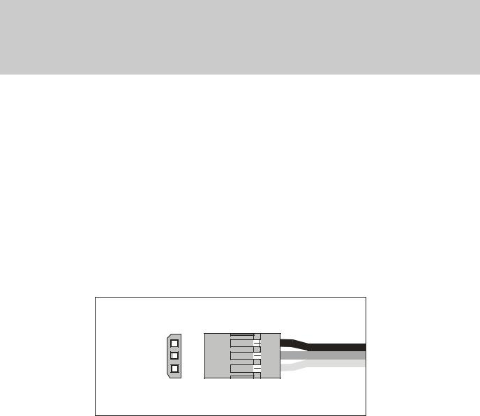
Your VG6000 unit is equipped the new universal AIRTRONICS “Z” connectors which are color coded blue, and are electrically compatible with the receivers of other radio control system manufacturers. The connectors are rugged but should be handled with care. Note that these connectors are not compatible with older AIRTRONICS R/C equipment unless Adapter p/n 99399Z is used!
“Z” CONNECTOR
(-)Negative (+)Positive Signal
AUDIO LOW VOLTAGE ALARM
Your VG6000 transmitter is equipped with an Audio Alarm which will sound whenever the transmitter batteries drop below 9.5 volts during transmitter operation. If the alarm sounds while you are flying, land immediately and don’t operate the transmitter until it has been charged for 12 hours. The transmitter should normally operate 120 to 150 minutes before the alarm sounds. If the alarm sounds even after the batteries have been on charge for the required time it indicates that there is a problem with either the battery pack or the transmitter, and you should contact AIRTRONICS about service.
THROTTLE HIGH WARNING
The VG6000 has a built in warning feature that will not allow you to use the transmitter if the throttle stick is not in the lowest position when you turn on the transmitter. If the throttle stick is not in the low position, when you turn it on, you will hear a continuous beeping sound and the display will read ( HI ). Pull the throttle stick down to the full low position. The normal menu will then be displayed and you can operate
and/or program the transmitter.
Page 7
 Loading…
#1
![]()
Meps1983
-

- Пользователи
-
- 46 сообщений
Участник форума

- Пол:Мужчина
- Город:Москва
Отправлено 29 окт. 2008 — 12:52
как эта апаратура sanwa vg-6000 40MHz.и какая ей цена? 
- Наверх
#2
![]()
lammomer
lammomer
-
- Пользователи
-
- 1 744 сообщений
Завсегдатай

- Пол:Мужчина
- Город:Санкт Петербург — Колпино
Отправлено 29 окт. 2008 — 15:11
Если честно то никак (( её скорее надо назва сРанва !! недавно друг изза отвалившегося проводка на канале элеронов сделал красивейшую морковку с 50 метров !!!
Мой совет бери JR или Futaba.
- Наверх
#3
![]()
Krat0S
Krat0S
-
- Пользователи
-
- 363 сообщений
Активный участник форума

- Пол:Мужчина
- Город:Краснодарский край
Отправлено 29 окт. 2008 — 15:38
Кстати по теме вопросик
Есть возможность купить с рук передатчик «JR/Pilоtage Max 66 ADT «, в комплектации: передатчик, аккум к нему, зарядка, два кварца, коробка, инструкция. По цене 4000р. Вроде в инет магазинах в районе 6000р он стоит.
Так вот собсна вопрос — стОит ли данный девайс того шобы рвать жилы на попе, чтобы выдернуть незапланированные 4к и купить его?
В данный момент у меня вообще w-fly, так что вопрос только — «СтОит ли?»
Сообщение отредактировал Krat0S: 29 окт. 2008 — 15:41
- Наверх
#4
![]()
arcad
arcad
-
- Пользователи
-
- 33 сообщений
Участник форума
Отправлено 29 окт. 2008 — 15:41
Нормальная аппаратура, но на сегодняшний день уже устарела. Лучше Optik или Sanva RD 8000.
Проводки на потенциометрах стиков действительно хлибкие, если родные Китайские, но народ их перепапивает и работает без проблем.
Цена, если только передатчик без ничего, не более 2500 р.
- Наверх
#5
![]()
arcad
arcad
-
- Пользователи
-
- 33 сообщений
Участник форума
Отправлено 29 окт. 2008 — 16:02
Если заявленные характеристики «JR/Pilоtage Max 66 ADT » 1 Вт. мощности действительно соответствуют, то это неплохой вариант.
- Наверх
#6
![]()
lammomer
lammomer
-
- Пользователи
-
- 1 744 сообщений
Завсегдатай
- Пол:Мужчина
- Город:Санкт Петербург — Колпино
Отправлено 29 окт. 2008 — 17:09
Да я всё понимаю .. перпаивают ….. НО тыже не будеш перепаивать в новой …. например машине провода на фары …… Просто после такого что было я сРанве больше не доверяю !!!!
Зато чтото про JR, Futaba — я о таких проблемах не слышал.
p.s. Моё мнение — надо сразу купить ХОРОШУЮ апаратуру минимум 9 каналов. И чтонибудь дешёвое — за 1000 — 1500 для симулятора.
Сообщение отредактировал lammomer: 29 окт. 2008 — 17:11
- Наверх
#7
![]()
Mursik
Mursik
-
- Пользователи
-
- 702 сообщений
Завсегдатай

- Пол:Мужчина
- Город:Санкт-Петербург
Отправлено 30 окт. 2008 — 13:11
Зато чтото про JR, Futaba — я о таких проблемах не слышал.
Что касается «проблем с проводами»: то, что Вы не слышали о них, совсем не значит, что их нет 
«Вы видите суслика — нет? А он есть!» © фильм
P.S. Вы же писали, что «не спец»? Откуда тогда такая страсть писать о том, чего Вы не знаете?  Может, тогда объясните, почему восемь каналов не «ХОРОШАЯ» аппаратура? на примере той же Санвы… ну, или любой другой.
- Наверх
Lastmanuals offers a socially driven service of sharing, storing and searching manuals related to use of hardware and software : user guide, owner’s manual, quick start guide, technical datasheets… DON’T FORGET : ALWAYS READ THE USER GUIDE BEFORE BUYING !!!
If this document matches the user guide, instructions manual or user manual, feature sets, schematics you are looking for, download it now. Lastmanuals provides you a fast and easy access to the user manual SANWA VG6000. We hope that this SANWA VG6000 user guide will be useful to you.
Lastmanuals help download the user guide SANWA VG6000.
 |
SANWA VG6000 : Download the complete user guide (2709 Ko) |
Manual abstract: user guide SANWA VG6000
Detailed instructions for use are in the User’s Guide.
[. . . ] VG6000
This equipment has been tested in accordance with the requirements contained in the appropriate Commission regulations. To the best of our knowledge, these tests were performed using measurement procedures consistent with industry or Commission standards and demonstrate that the equipment complies with the appropriate standards. Each unit manufactured, imported or marketed, as defined in the Commission’s regulations, will conform to the sample(s) tested within the variations that can be expected due to quality production and testing on a statistical basis. We further certify that the necessary measurements were made by Kansai Electronic Industry Development Center, Ikoma Emission Measurement Station, 10830, TakayamaCho, Ikoma-City, Nara, 630-01 Japan.
Page 1
VG6000
TABLE OF CONTENTS
Page #
2 3 4 5 6 7 8 9 10 11 12 13 14 15 16 17 18 19 20 21 22 23
Table of Contents Radio Control System and Specifications Academy of Model Aeronautics / Initial Preparation Transmitter Features Airborne System Connections / NiCd Charging Infomation Airborne Components / Warning Alarms Transmitter Battery Removal / Stick Length Adjustment Transmitter Stick Tension Adjustment Trainer System Microprocessor / Bar Graph Voltage Indicator Features Descriptions Stick and Switch Functions Dual Rates / Exponential End Point Adjustment / Servo Centering Servo Reversing / V-Tail Mixing Delta Wing / Flaperons Flaperons CONTINUED / Differential Flap to Elevator Mixing / Aileron to Rudder Mixing Model Select / Elevator to Flap Mixing Throttle Cut / Count Down Timer Sound Click / Battery Voltage Display Model Settings
Page 2
VG6000
RADIO CONTROL SYSTEM
Thank you for selecting the Airtronics VG6000 Radio System. [. . . ] NOTE: using Negative expo will make your ailerons and elevator more sensitive in the middle stick area which will make the aircraft reactions very fast. Adjustment is from +100 to -100.
Page 14
VG6000
END POINT ADJUSTMENT (
EPA )
EPA will allow you to increase or decrease the total amount of travel the servo has. EPA is available on all channels and should only be used to fine tune maximum servo movement. All of your linkages and control surfaces should be as close as possible to the model specifications before decreasing or increasing EPA. A good example for EPA would be when you want to use 2 aileron servos on 2 different channels and you want to setup both to have the same amount of throws to each other up and down. NOTE: You must have the FLAPERON feature activated in order to use 2 sperate aileron servos. To use EPA, move the cursor to the EPA using the FUNCTION keys. Next use the CH/TIMER key to change to the channel you want to set your EPA. Next move the stick in the direction you want to increase or decrease and take note the arrows on the LCD screen. They will point in the direction you are adjusting. EPA can be set independently from side to side or up and down. Adjustment is from 0 to 150% in each direction.
SERVO CENTERING
( CENT )
Servo centering to a great feature when it comes to setting up a new model and or setting your servo arms to right at 90 degrees. When using servo centering, take note that it will change not only the center position of the servo but as well change both left and right end points. Example, you installed a servo arm on your servo but it will not lineup perfectly 90% to the servo. You now can adjust the servo centering so now the arm is at 90% of the servo. Servo centering can be adjusted from 0 to 100% but is best kept within + or — 10% any more than that you will need to try another servo arm or adjust your linkage better. To use CENT, move the cursor to the CENT using the FUNCTION keys. Next use the CH/TIMER key to change to the channel you want to set your CENT. Adjustment is from +100 to -100.
Page 15
VG6000
SERVO REVERSING
( REV )
After setting up your aircraft you find that the control surface is moving in the wrong direction, you can use the REV to reverse the direction that the servo operates. REV is available on all channels.
To use REV, move the cursor to the REV using the FUNCTION keys. Next use the CH/TIMER key to change to the channel you want to change the REV. Next press either the INC+ or DEC- to change from NOR to REV.
V-TAIL MIXING
( V-TAIL )
If you have a V-tail aircraft, you will need to activate this feature. [. . . ] Throttle cut only works when the stick is in the low position. Make sure the throttle barrel on your engine will go below the lowest idle position before adjusting throttle cut. Default is «0» setting are from 15 to -15
COUNT DOWN TIMER
( TIMER )
Count down timers help to remind you that it’s time to land meaning lets get it down before we run out of fuel. If you know how long a normal flight is on your aircraft «example» 15:00 minutes, you can set the down timer to sound off at 13:00 minutes. [. . . ]
DISCLAIMER TO DOWNLOAD THE USER GUIDE SANWA VG6000
Lastmanuals offers a socially driven service of sharing, storing and searching manuals related to use of hardware and software : user guide, owner’s manual, quick start guide, technical datasheets…
In any way can’t Lastmanuals be held responsible if the document you are looking for is not available, incomplete, in a different language than yours, or if the model or language do not match the description. Lastmanuals, for instance, does not offer a translation service.
Click on «Download the user manual» at the end of this Contract if you accept its terms, the downloading of the manual SANWA VG6000 will begin.
|
|
Радиоуправляемые и стендовые модели. Авиа, авто, судо, квадрокоптеры. Ремонт и консультации |
ВНИМАНИЕ МАГАЗИН В НОГИНСКЕ |
Корзина заказа
|