
Личный кабинет
Авторизация
Регистрация
RUB, руб.
- EUR, €
- RUB, руб.
Сервис-партнёр RATIONAL
Запчасти Rational, аксессуары. Гарантийный ремонт. Проддажа пароконвектоматов по специальным программам.
Рады общению с 10 до 19 часов в рабочие дни
+79049845111
0
Корзина
Пустая
Главная страница » Инструкции pdf
Инструкции pdf

Руководство по эксплуатации пароконвектомата RATIONAL iCombi Pro с 2020 года.

Руководство по эксплуатации пароконвектомата RATIONAL iCombi Classic с 2020 года.

Руководство по эксплуатации пароконвектомата RATIONAL SelfCooking Center whitefficiency/ 5Senses 2011-2017

Руководство по эксплуатации пароконвектомата RATIONAL Combi Master Plus 2011-2017

Руководство по эксплуатации пароконвектомата RATIONAL SelfCooking Center 2004-2011

Руководство по эксплуатации пароконвектомата RATIONAL Combi Master 2004-2011

Книга рецептов для ручной эксплуатации
Воспользуйтесь уникальным опытом лучших шеф паворов.

Руководство по применению. Ночное приготовление, смешанная загрузка, вакуумная упаковка.
Коллектив отдыхает а оборудование работает

Руководство по применению. Finishing
Уникальные алгоритмы оптимизации процессов подготовки и подачи блюд.
Подготовка к банкету без стресса.

Моющие средства RATIONAL
Использование оригинальных моющих средств защитит ваше оборудование от вредных воздействий и обеспечит бесперебойную работу в течении всего срока эксплуатации.
Страница 1 из 2
-
Электрические схемы, артикулы деталей проконвектомата Rational SCC 61E 3NAC 400 50-60 Hz (от 05.05.2004г.).
Вложения:
-
Каталог запчастей пароконвектомата Rational SCC 61E.
Вложения:
mickey009 и кип нравится это.
-
Кулинарная книга Rational SCC.
Вложения:
searcher и 0101 нравится это.
-
Электрические схемы с артикулами деталей для Rational SCC — индекс Е.
Вложения:
-
Каталоги запчастей для электрических моделей Rational SCC — индекс G. (С Care Control)
Вложения:
-
Каталог запчастей на электрические модели Rational SCC — индекс E.
Вложения:
-
Каталог запчастей на газовые модели Rational SCC — индекс E.
Вложения:
-
Каталог запчастей на электрические модели Rational SCC — индекс G.
Вложения:
-
Каталог запчастей газовые модели Rational SCC — индекс G.
Вложения:
-
Запасные части для аксессуаров Rational.
Вложения:
-
Справочник на пароконвектоматы Rational.
Вложения:
-
Техническая информация на пароконвектоматы Rational.
Вложения:
-
2004.RAR
- Размер файла:
- 2 МБ
- Просмотров:
- 470
-
2005.RAR
- Размер файла:
- 3,4 МБ
- Просмотров:
- 280
-
2006.RAR
- Размер файла:
- 2,3 МБ
- Просмотров:
- 294
-
2007.RAR
- Размер файла:
- 1,5 МБ
- Просмотров:
- 277
-
2008.RAR
- Размер файла:
- 2 МБ
- Просмотров:
- 269
-
2009.RAR
- Размер файла:
- 1,1 МБ
- Просмотров:
- 325
-
2010.RAR
- Размер файла:
- 1,5 МБ
- Просмотров:
- 314
-
2011.RAR
- Размер файла:
- 606,8 КБ
- Просмотров:
- 592
-
-
Руководство по модификации пароконвектоматов Rational.
Вложения:
-
2004.RAR
- Размер файла:
- 1,2 МБ
- Просмотров:
- 260
-
2005.RAR
- Размер файла:
- 10,4 МБ
- Просмотров:
- 188
-
2006.RAR
- Размер файла:
- 3,1 МБ
- Просмотров:
- 200
-
2007.RAR
- Размер файла:
- 4,3 МБ
- Просмотров:
- 209
-
2008.RAR
- Размер файла:
- 2,5 МБ
- Просмотров:
- 204
-
2009.RAR
- Размер файла:
- 2,2 МБ
- Просмотров:
- 228
-
2010.RAR
- Размер файла:
- 2,2 МБ
- Просмотров:
- 340
-
-
Руководство по применению для пароконвектоматы Rationa SCC.
Вложения:
-
Руководство по эксплуатации пароконвектомата Rationa SCC CareControl.
Вложения:
-
Электрическая схема с артикулами деталей для Rational SCC 102
— индекс ЕВложения:
-
Добрый день. Произошла такая проблема. Rational scc, по размеру 102, электрический. При включении через клавишу сверху o/l срабатывает контактор и подается питание на тэны. Т. Е. Включаю, но не запускаю ничего, ни программы, ни режимы, ни диагностику, а питание на тэны подается. Проверяли плату управления на другом аппарате, такой проблемы нет, думаю еще силовую плату проверить так же, но единственное, на что я грешил, а именно реле, вроде в исправном состоянии. Прошу помощи, если кто сталкивался, либо подскажите, куда рыть. Спасибо.
-
вроде в исправном это как вы определили ?
Страница 1 из 2
Поделиться этой страницей
![]()
Training Manual
SCC Line
SelfCooking Center — Combi Master
Edition 09-2007

Training Manual
SCC Line
Edition 09 — 2007
General hints:
Isolate the appliance from mains supply before opening the appliance
When working with chemicals, i.e. aggressive cleaning materials always wear protective clothing, goggles and gloves!
After maintenance / repair the appliance must be checked for electric safety in accordance with your national, state and local requirements!
Whenever working on any gas component like:
Gas valve, gas blower and / or changing connected type of gas a detailedue gas analysis MUST be done using adequate CO and CO2 measuring equipment! This shall ONLY be done by trained technicians! Always check appliance for possible gas leakages!
|
Part1: CM Technology |
|
|
CM Technique from 04 — 2004 |
4 |
|
Water level control Steam Generator |
6 |
|
RATIONAL SC Automatic |
7 |
|
Steam Control CM |
8 |
|
Additionaly functions CM from 04 — 2004 |
10 |
|
CM PCB (42.00.004) |
12 |
|
Motor for CM 40.00.274 |
13 |
|
CM — Sequence of events |
14 |
|
Service level CM from 04 — 2004 |
19 |
|
Service level: dP — Diagnostic Program |
20 |
|
Service Level: ER — Error code history |
21 |
|
Failure Codes CM „ER“ |
22 |
|
Service Level: rt — Running Time |
23 |
|
Service level: SE — Basic settings |
24 |
|
Service level: SE — Function test |
26 |
|
CM Gas from 04 — 2004 |
28 |
|
Identification of the different gas burners / Gas blowers: |
29 |
|
Sequence of events of Burner and Ignition control |
30 |
|
Changing installation altitude: CM gas |
32 |
|
Checking of dyn. input gas flow pressure |
33 |
|
Flue gas analysis |
34 |
|
Changing Gas blower speed |
37 |
|
Burner adjustment |
38 |

|
Part2: SCC Technology |
|
|
SCC Control Panel |
39 |
|
Display up to Software version SCC 01-07-12 |
40 |
|
Display since Software version SCC 02-01-01 |
42 |
|
Display Programming / CleanJet SCC 02-01-01 |
44 |
|
SCC Electric from 04-2004 |
46 |
|
SCC Operator pcb (42.00.002) |
48 |
|
I/O PCB SCC (40.00.049) |
49 |
|
Motor for CM 40.00.274 |
50 |
|
Humidity control SCC |
51 |
|
Service level SCC |
60 |
|
SCC Diagnostic Mode |
61 |
|
SCC Running Times |
65 |
|
Basic Settings |
69 |
|
RESET |
73 |
|
Function test |
74 |
|
Download of unit service data |
78 |
|
HACCP |
82 |
|
Service messages |
84 |
|
Calibration SCC |
88 |
|
Control Drain Valve 54.00.357 |
90 |
|
SCC Gas |
|
|
SCC Gas from 04-2004 |
92 |
|
Identification of the different gas burners / Gas blowers: |
94 |
|
Sequence of events of Burner and ignition control |
95 |
|
Gas conversion : SCC Gas |
96 |
|
Adjustment of installation altitude above sea level |
97 |
|
Flue gas analysis: SCC gas |
98 |
|
Burner adjustment |
100 |
|
Changing gas blower speed SCC Gas |
101 |
|
Part3: Common information |
|
|
Flash SCC Software |
102 |
|
Software update CM units |
104 |
|
User instruction electrical descaler pump |
108 |
|
RATIONAL Commissioning SCC-CM |
110 |
|
Preventative maintenance SCC / CM |
114 |
|
Water info |
118 |
|
Part4: Fault list SCC — CM |
120 |
|
Part5: Circuit diagram (Training version 3NAC 400V |
138 |
|
SCC Service reference |
192 |

S
C
M
CM Technique from 04 — 2004
Steam
Hot Air
Combi Steam
Low Temperature Steam
Finishing
Cool Down
 Cabinet temperature display
Cabinet temperature setting
Timer
Core temperature

 Time — Core temperature display
Time — Core temperature setting
-4-

CM Technique from 04 — 2004
B1 F4
B3
S2
B5
F3
M1
M4
S3
B2
Y1 Y2
|
B1 |
Thermocouple cabinet |
|
B2 |
Thermocouple quenching / Steam control |
|
B3 |
Thermocouple core temperature |
|
B5 |
Thermocouple steam generator (preheating, 180°C (356°F) max) |
|
F3 |
Safety temperature limiter steam generator 160°C |
|
F4 |
Safety temperature limiter cabinet 360°C |
|
Y1 |
Solenoid valve lling |
|
Y2 |
Solenoid valve quenching |
|
M1 |
Fan motor (without jumper) |
|
M4 |
Pump SC-Automatic |
|
S2 |
Level electrode |
|
CM 201/202 only: |
|
|
M2 |
Fan motor top (with jumper) |
-5-

S
|
C |
Water level control Steam Generator |
|
M |
S2
|
B5 |
S2 |
V AC |
|
|
F3 |
|||
 M4
M4
B2
Y1

 Y2
Y2 
|
Center S2 ==> Ground: |
2 — 6V AC: |
water level too low |
|
steam heating must switch OFF |
||
|
solenoid valve lling Y1 ON |
||
|
Center S2 ==> Ground: |
0V AC: |
water level reached |
|
steam heating can switch ON |
||
|
solenoid valve lling Y1 switched OFF |
X12 |
Every 2 minutes steam elements will switch off for water level control
Notes:
-6-

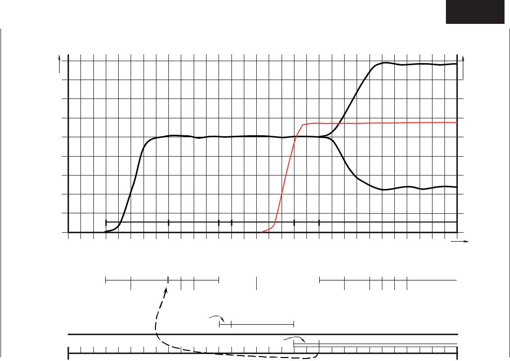
RATIONAL SC Automatic
During the production of steam, the concentration of minerals inside the steam generator will increase over time. These minerals settle on the heating elements and heat exchanger as well as the interior steam generator walls.
In order to reduce this effect the steam generator will be pumped off and ushed regularly depending on the duration of steam production. This process needs approximately 45 seconds.
After emptying the steam generator it will be lled automatically with fresh water.
There are 4 conditions to start this SC Automatic:
1.Heating time of the steam generator must exceed 60 min. (CM — 45 min.)* and
2.the temperature of the thermocouple inside steam generator (B5) must be below 65°C (149°F) and
3.the temperature of the thermocouple inside interior cabinet (B1) must be below 70°C (158°F) and
4.the unit is switched ON.
* — can be adjusted from 20-120min
In case the unit is used permanently the above mentioned temperature conditions can not be met.
In this case the following 2 conditions apply:
1.The heating time of the steam generator reaches the twice the set duration*, i.e. 120 min. (CM — 90 min.) and
2.the unit door is open for longer than 30 seconds
After completion of the SC-Automatic the timer accumulating the steam heating time is re-set to zero.
-7-

S
|
C |
Steam Control CM |
|
M |
Intelligent steam control via quenching sensor |
1.Filling of interior cabinet based on time and temperature control of B2 quenching sensor
2.After steam saturation inside cabinet steam will also ll quenching chamber
|
°C / °F |
B1 — 100°C(212°F) |
3. Depending on the frequency of temperature |
|
70°C |
raise of the quenching sensor B2 the |
|
|
duration of the next steam supply is |
||
|
(158°F) |
B2 — 1 |
|
|
calculated. |
||
|
B2-1: B2 temperature with partial load |
||
|
B2 — 2 |
B2-2: B2 temperature with full load |
|
|
4. The amount of steam inside the cabinet is |
||
|
t (sec) |
||
|
directly depending on the temperature |
||
|
variation of quenching sensor B2. |
Notes:
-8-

-9-

|
S |
C |
Additionaly functions CM from 04 — 2004 |
|
M |
Below are listed the additionaly functions for the user / operator:
1.Cleaning program
1)Cool down cabinet below 60°C
2)Spray inside cabinet with Rational cleaner
3)Close cabinet door
4)Select „Cool Down
5)Press core temperature key for 10 sec.
6) „CLEn“ will show in cabinet temperature display
7) Press timer key 1x; Cleaning program starts automatically (open cabinet door and rinse interior cabinet after 40 min.) Close door again. Since Software version C1-06-05 a 10 min step hot air will follow to dry the interior cabinet.)
 After end of program, leave cabinet door open over night.
2. Empty steam generator
This should be done after each installation to verify free drain connection and prior to disconnection the unit for storage.
1)Open cabinet door
2)Select „Cool Down“
3) Press core temperature key for 10 sec.
4) „CLEn“ will be shown in cabinet temperature display
5) Select „SC“ with temperature dial
6) Close water tap
7) Press timer key 1x and remain on „Cool Down“ position for about 45 sec.
3.Descaling program
1)Open cabinet door
2)Select „Cool Down“
3) Press core temperature key for 10 sec.
4) „CLEn“ will be shown in cabinet temperature display
5) Select „CALC“ with temperature dial
6) Press timer key 1x and follow procedure of the decalci cation instruction. (See user manual CM).
-10-
![]()
Additionaly functions CM from 04 — 2004
S
C
M
4.Changing temperature display from °C to °F
1)Select any mode
2) Press timer and core temperature key simultaneously for 10 sec. until Display changes from °C to °F or vice versa
3) Release both keys
Notes:
-11-

|
S |
CM PCB (42.00.004) |
|
|
C |
||
|
M |
CM PCB (42.00.047) from 02-2006 (without transformer) |
|
|
42.00.004 |
|
0,1 AT |
2 AT |
|
F1 |
F2 |
|
Transformer |
X7 |
|
X19 |
|
|
1 |
|
|
X20 |
|
|
1 |
42.00.047
|
2 AT |
||||||||||
|
X16 |
F6 |
|||||||||
|
2 AT |
||||||||||
|
F6.1 |
X7 |
|||||||||
|
X19 |
||||||||||
X63 
1
|
X20 |
|
|
1 |
|
|
X18 |
|
|
X23 |
|
|
1 |
|
|
X31 |
|
|
X30 |
RS 485 |
|
RS 232 |
|
X8 |
||
|
Temperature |
X12 |
|
|
1 |
||
|
potentiometer |
||
|
X26 |
||
|
X50 |
X27 |
|
|
1 |
||
X2 B3 Core temperature
X3 B1 Interior cabinet
X4 B2 Quenching / Steam control
X6 B5 Steam generator
X7 ON — OFF switch
X8 Buzzer
X12 Level electrode
X 16power supply from transformer (42.00.047)
X18 SC — pump
X19 Solenoid valves
X20 Energy optimising / Sicotronic
X23 Vent hood (signal door open / closed)
X24 SSR
X26 SSR pulsing (USA version only)
X27 Door contact switch
X30 Serial interface (RS232)
X31 BUS interface
X32 Timer / Core Temp. Potentiometer
X50 external EEPROM
X63 Not used
1 Counting sequence
X2 X6 X4 X3
|
1 |
X24 |
1 |
X32 |
|||||||||
Since February 2006 PCB 42.00.004 is replaced by 42.00.047. (Conversion kit: 87.00.139, pls. see Technical info 04-06)
The transformer on the new PCB 42.00.047 is no more existing and replaced by external transformer 40.00.227
-12-

Motor for CM 40.00.274

 Jumper
LED
Jumper 40.01.581 is used on oor model 201 and 202 for top position motor only! Jumper is not used on models 61 — 102 with one motor only! (Service 34 will be shown!)
LED code fan motor SCC and CM from 04/2004
|
Reason |
||
|
1x |
Motor doesn’t start, no changing |
Check for motor blockage or change motor. |
|
signal from hallsensor |
||
|
2x |
Voltage too low on motor pcb |
Check supply voltage or |
|
change motor. |
||
|
3x |
Voltage too high on motor pcb |
Check supply voltage or |
|
change motor. |
||
|
4x |
rpm measurement defective |
Change motor. |
|
5x |
Motor pcb temperature >105°C |
Check cooling system (cooling fan, air intake |
|
filter), otherwise change motor |
||
|
6x |
Supply voltage <80V |
Check power supply |
|
(F1-F2) |
||
|
7x |
Motor pcb defective |
Change motor. |
|
8x |
Motor pcb defective |
Change motor. |
|
Remedy |
-13-

|
S |
CM — Sequence of events |
C M
Mode: Steam 100°C (212°F)
Temp. preset, not adjustable
B1 F4
B3
S2
B5
F3
M1
M4
S3
B2
Y1 Y2
|
Function Step |
Responsible sensor |
1.Select Steam mode
2.Select time or core temperature
|
3. |
Close cabinet door |
Reed switch S3 |
|
|
4. |
Check water level inside steam generator |
Level electrode S2 inside Steam Generatorr |
|
|
5. |
Preheat steam generator, |
Thermocouple B5 inside Steam Generator |
|
|
if B5 is below 85°C (185°F); |
|||
|
6. |
Timer starts after successful preheating |
Logic on PCB |
|
|
(blinking dot in Display) |
|||
|
7. |
Steam supply up to steam saturation |
Quenching sensor B2 |
|
|
inside cabinet |
(Steam control) |
||
|
8. |
Hot Air supply (only 50%) when set |
Cabinet sensor B1 |
|
|
temperature (100°C/212°F) can not be |
|||
|
reached in time by Steam alone |
|||
|
9. |
Quenching (set to 70°C/158°F) |
Quenching sensor B2 |
|
-14-

|
CM — Sequence of events |
S |
Mode: Low temperature steam
Temp. range 30-99°C (86-210°F)
C M
B1 F4
B3
S2
B5
F3
M1
M4
S3
B2
Y1 Y2
Function Step
1.Select Low temperature steam mode Set temperature 30-99°C (86-210°F)
2.Select time or core temperature
3.Close cabinet door
4.Check water level inside steam generator
5.Preheat steam generator, if B5 is below 85°C (185°F);
6.Timer starts after successful preheating (blinking dot in Display)
7.Steam supply until set temperature inside cabinet is reached
8.Hot Air supply (only 50%) when set temperature can not be reached in time by Steam alone
Responsible sensor
Reed switch S3
Level electrode S2 inside Steam Generatorr Thermocouple B5 inside Steam Generator
Logic on PCB
Cabinet sensor B1
Cabinet sensor B1
|
9. Quenching (set to 70°C/158°F) |
Quenching sensor B2 |
Note: Reduction of fan motor speed
In case the actual temperature is higher than the set temperature for longer than 2 minutes, the fan speed will be reduced automatically.
-15-

|
S |
CM — Sequence of events |
C M
Mode: Combination
Temp. range 30-300°C (86-572°F)
B1 F4
B3
S2
B5
F3
M1
M4
S3
B2
Y1 Y2
|
Function Step |
Responsible sensor |
1.Select Combi mode
Set temperature 30-300°C (86-572°F)
2.Select time or core temperature
|
3. |
Close cabinet door |
Reed switch S3 |
|
4. |
Check water level inside steam generator |
Level electrode S2 inside Steam Generatorr |
|
5. |
Preheat steam generator, |
Thermocouple B5 inside Steam Generator |
|
if B5 is below 85°C (185°F); |
||
|
6. |
Timer starts after successful preheating |
Logic on PCB |
|
(blinking dot in Display) |
||
|
7. |
Hot Air supply until set temperature |
Cabinet sensor B1 |
|
inside cabinet. Hot air has priority |
||
|
8. |
Steam supply up to steam saturation |
Quenching sensor B2 |
|
inside cabinet |
(Steam Control) |
|
|
9. |
Quenching (set to 70°C/158°F) |
Quenching sensor B2 |
Note: Reduction of fan motor speed
In case the actual temperature in the range of 30-99°C (37-210°F) is higher than the set temperature for longer than 2 minutes, the fan speed will be reduced automatically.
-16-

|
CM — Sequence of events |
S |
|
|
F |
C |
|
|
Mode: Finishing |
||
|
M |
||
|
Temp. range 30-300°C (86-572°F) |
B1 F4
B3
S2
B5
F3
M1
M4
S3
B2
Y1 Y2
|
Function Step |
Responsible sensor |
1.Select Finishing mode
Recommended temperature 100-140°C (212-284°F)
2.Select time or core temperature
|
3. |
Close cabinet door |
Reed switch S3 |
|
4. |
Check water level inside steam generator |
Level electrode S2 inside Steam Generatorr |
|
5. |
Preheat steam generator, |
Thermocouple B5 inside Steam Generator |
|
if B5 is below 85°C (185°F); |
||
|
6. |
Timer starts after successful preheating |
Logic on PCB |
|
(blinking dot in Display) |
||
|
7. |
Hot Air supply |
Cabinet sensor B1 |
|
Electric units: 12 sec on — 6 sec off |
||
|
Gas units: 30 sec on — 15 sec off |
||
|
8. |
Steam supply |
Quenching sensor B2 |
|
Electric units: 6 sec on — 12 sec off |
(Steam Control) |
|
|
Gas units: 15 sec on — 30 sec off |
||
|
9. |
Quenching (set to 70°C/158°F) |
Quenching sensor B2 |
Note: Reduction of fan motor speed
In case the actual temperature in the range of 30-99°C (37-210°F) is higher than the set temperature for longer than 2 minutes, the fan speed will be reduced automatically.
-17-

|
S |
CM — Sequence of events |
C M
Mode: Hot Air
Temp. range 30-300°C (86-572°F)
B1 F4
B3
S2
B5
F3
M1
M4
S3
B2
Y1 Y2
|
Function Step |
Responsible sensor |
1.Select Hot Air mode
Set temperature 30-300°C (86-572°F)
2.Select time or core temperature
|
3. |
Close cabinet door |
Reed switch S3 |
|
4. |
Hot Air supply unitl set temperature |
Cabinet sensor B1 |
|
is reached |
||
|
8. |
Quenching (set to 90°C/194°F) |
Quenching sensor B2 |
Note: Reduction of fan motor speed
In case the actual temperature in the range of 30-99°C (37-210°F) is higher than the set temperature for longer than 2 minutes, the fan speed will be reduced automatically.
-18-

|
Service level CM from 04 — 2004 |
||||||
|
1) |
Switch unit ON |
|||||
|
2) |
On operator PCB set DIP switch 1 to „ON“ position |
|||||
|
on |
||||||
|
1 |
2 |
3 |
4 |
|||
|
3) |
Select service package with timer dial: |
|||||
|
Diagnostic Program |
||||||
|
Error code history |
||||||
|
Running times |
||||||
|
Basic settings |
||||||
|
4) |
Activate with core temperature key the desired service package |
|||||
|
5) |
Select with timer dial the desired step |
|||||
|
6) |
Activate selected step by pressing timer key |
|||||
|
on |
7) |
To de-activate service package set DIP switch 1 to „OFF“ position. |
||||
|
1 |
2 |
3 |
4 |
|||
|
Function Test |
||||||
|
1) |
Switch unit ON |
|||||
|
on |
2) |
Auf Bedienplatine DIP Schalter 3 auf „ON“ Stellen |
||||
|
1 |
2 |
3 |
4 |
|||
|
First step of function test is displayed. |
||||||
|
3) |
Select desired step of function test with timer dial |
|||||
|
4) |
Activate selected step by pressing timer key |
|||||
|
5) |
Activate selected step with core temperature key |
|||||
|
6) To de-activate function test set DIP switch 3 to „OFF“ position. |
||||||
|
on |
||||||
|
1 |
2 |
3 |
4 |
|||
S
C
M
42.00.004
0,1 AT 2 AT
F1 F2
Transformer
X7
X19
1

 X20
X20
1
42.00.047
|
2 AT |
||
|
X16 |
F6 |
|
2 AT
F6.1
X63 
|
1 |
|||
|
off |
3 2 |
on |
X30 |
|
4 |
RS 232 |
X7
X19
1

 X20
X20
1
X18
X23
1
X31
RS 485
X8 
X12
1
|
X26 |
||
|
X50 |
X27 |
|
|
1 |
||
X2 X6 X4 X3
|
1 |
X24 |
1 |
X32 |
||||
Notes:
-19-

Service level: dP — Diagnostic Program
|
dP # |
Description |
Connector Cabinet display Timer display Comment |
|
Software |
Software |
||||
|
dP 1 |
Software Version |
version: C — 1 — |
Version:06.05 |
||
|
dP 2 |
B1 Cabinet sensor |
X 3 |
actual value |
max value |
|
|
dP 3 |
B2 Quenching sensor |
X 4 |
actual value |
max value |
|
|
dP 4 |
B3 Core sensor |
X 2 |
actual valuet |
max value |
|
|
dP 5 |
B5 Steam generator sensor |
X 6 |
actual value |
max value |
|
|
dP 6 |
PCB temperature |
actual value |
max value |
||
|
dP 7 |
S3 Door contact |
X27:(1-2) |
S3: 1 — 0 |
1 — 0 |
|
|
X12:(1-4) |
S2 |
Y1: 1 — 0 |
|||
|
dP 8 |
S2 Water level steam |
X19:(1-3) |
Y1 |
||
|
generator |
Temp. B5 |
0 — 1 — 2 |
|||
|
dP 9 |
Steam elements |
||||
|
0 — off; 1 — 50%; 2 — 100% |
Temp. B1 |
0 — 1 — 2 |
|||
|
dP 10 |
Hot Air elements |
||||
|
0 — off; 1 — 50%; 2 — 100% |
BUS |
Set rpm |
actual rpm |
||
|
dP 11 |
Speed fan motor top |
||||
|
BUS |
Set rpm |
actual rpm |
|||
|
dP 12 |
Speed fan motor bottom |
||||
|
X 20 |
1 — 0 |
||||
|
dP 13 |
Energy optimising |
||||
|
(Sicotronic) |
X 26 |
1 — 0 |
|||
|
dP 14 |
SSR pulsing (US version) |
||||
|
61 — 202 |
ELE — GAS |
||||
|
dP 15 |
Unit size and type |
||||
|
dP 16 |
Flame Current Steam |
x.x A* |
|||
|
dP 17 |
Flame Current Hot Air top |
x.x A* |
|||
|
dP 18 |
Flame Current Hot Air bottom |
x.x A* |
|||
Reset by pressing
for 5 sec.
+ 
Reset by pressing
for 5 sec.
 +
+ 
Reset by pressing
for 5 sec.
 +
+ 
Reset by pressing
for 5 sec.
 +
+ 
Reset by pressing
USA version only
since SW Version: C1-06-05 ( ame current)
since SW Version: C1-06-05 ( ame current)
since SW Version: C1-06-05 ( ame current)
*With SW Version C1-06-05 the ame current will show as 20-24 A
(This value must be divided by 4 to get the correct ame current e. g. 22:4 = 5,5 A.) Starting with SW version C1-07-01 the actual ame current is shown .
-20-
![]()
Service Level: ER — Error code history
Since software version C1-07-01 the last 10 general error messages are
shown (applies for electric and gas models)
|
Er |
When timer key is pressed the error code will be displayed. i.e.: |
|
|
Er1 |
3 |
B1 Cabinet sensor defective |
|
Er2 |
14 |
Y1 Filling solenoid defective |
|
Er3 |
||
|
—- |
||
|
ER10 |
Note: Er1 — Er10 is a consecutive counting
Number 1-24 are error codes which are generated by the pcb
Gas error GE: (gas units only!)
Since software version C1-07-01 the last 16 gas error messages are shown in addition to the general error messages
|
GE11 |
20 |
No rpm signal |
|
GE12 |
32 |
No ame after 5 ignition sequences |
|
GE13 |
||
|
— |
||
|
GE25 |
Note: GE11 — 25 is a consecutive counting
Number 1-43 are internal error codes which are generated by the ignition box
Indication of ignition box error messages (1-32 is shown to the operator as „rES“):
|
1 |
Hot air or Steam |
no gas, gas valve or electrode defective |
|
|
14 |
Hot air |
gas valve controll, change ignition box |
|
|
19 |
Hot air |
no ame because ame current is too low |
|
|
check burner setting, ame current, ignition cable and plug |
|||
|
20 |
Hot air |
wrong or no rpm signal from gas blower |
|
|
check gas blower, power supply gas blower and control harness of gas blower |
|||
|
22 |
Hot air |
no ame after 5 ignition sequences |
|
|
no gas, gas valve or electrode defective |
|||
|
24 |
Steam |
gas valve controll, change ignition box |
|
|
29 |
Steam |
no ame because ame current is too low |
|
|
check burner setting, ame current, ignition cable and plug |
|||
|
30 |
Steam |
wrong or no rpm signal from gas blower |
|
|
check gas blower, power supply gas blower and control harness of gas blower |
|||
|
32 |
Steam |
no ame after 5 ignition sequences |
|
|
no gas, gas valve or electrode defective |
|||
|
Possible failure in case of „E21“ |
|||
|
33, 36 |
Change ignition box |
||
|
35 |
Check frequency of main |
||
|
39 |
Hot air |
Check burner setting, ignition electrode and distance,and ame current |
|
|
40 |
Hot air |
Check ignition cable |
|
|
42 |
Steam |
Check burner setting, ignition electrode and distance,and ame current |
|
|
43 |
Steam |
Check ignition cable |
|
|
Is shown on display „CHnG PoL“ |
|||
|
34 |
Change polarity of mains |
All other numbers (2-13, 15-18, 21, 23, 25-28, 31): change ignition box
-21-

S
C M
Failure Codes CM „ER“
|
Int. cab. |
Timer |
Failure explanation |
Description |
|
display |
display |
||
|
H2o |
OPEn |
H2O open |
Lack of water / open water tap |
|
CHnG |
PoL |
Change Polarity |
Phase / Neutral (only gas units) |
|
Timer |
Int. cab. |
Part concerned |
Description |
|
display |
display |
||
|
(E -press |
|||
|
core temp. |
|||
|
key) |
|||
|
E1 |
external EEPROM |
Not initialised |
|
|
E2 |
Timeout of external |
Heating blocked by the extern. energyopti- |
|
|
power optimising system |
mising system for longer 2 min. |
||
|
(Sicotronic) |
|||
|
E3 |
B1 Interior cabinet sensor |
Sensor broken |
|
|
E4 |
B2 Quenching sensor |
Sensor broken |
|
|
E5 |
B3 Core sensor |
Sensor broken |
|
|
E6 |
B5 Sensor steam generator |
Sensor broken |
|
|
E7 |
Thermocouple on PCB |
Sensor broken |
|
|
E8 |
Poti interior cabinet |
Defective |
|
|
E9 |
Poti timer/core temperature |
Defective |
|
|
E10 |
External EEPROM |
Defective |
|
|
E11 |
Mode switch |
After 5 sec switching on the unit, a cooking |
|
|
mode couldn‘t be identi ed |
|||
|
E12 |
1 St |
Fan motor 1 (bottom) |
St = Status (probably Motor defect) |
|
1 Co |
Fan motor 1 (bottom) |
Co = Communication,(Bus failure) |
|
|
E 12 |
2 St |
Fan motor 2 (top) |
St = Status (probably Motor defect) |
|
2 Co |
Fan motor 2 (top) |
Co = Communication,(Bus failure) |
|
|
E13 |
M4 SC-pump |
Mal function |
|
|
E14 |
Solenoid valve lling Y1 |
Mal function |
|
|
E15 |
PCB temperature |
above 85°C (185°F) |
|
|
E16 |
Steam generator |
Temperature B5 above |
|
|
E17 |
Steam generator |
180°C (356°F) |
|
|
Temperature B5 below -5°C (23°F) |
|||
|
E18 |
Interior cabinet temp. |
Temperature B1 above 340°C (644°F) |
|
|
E19 |
free |
||
|
E20 |
1_ |
Ignition box 1 |
Ignition box does not reply, Bus failure |
|
E20 |
2_ |
Ignition box 2 |
Ignition box does not reply, Bus failure |
|
E21 |
1xx |
Ignition box 1 Steam |
Ignition box defective (change box) |
|
E21 |
2xx |
Ignition box 1 Hot air |
Ignition box defective (change box) |
|
E21 |
3xx |
Ignition box 2 Hot air |
Ignition box defective (change box) |
|
E22 |
1xx |
Ignition box 1 Steam |
Testing of ignition and monitoring |
|
necessary |
|||
|
E22 |
2xx |
Ignition box 1 Hot air |
Testing of ignition and monitoring |
|
necessary |
|||
|
E22 |
3xx |
Ignition box 2 Hot air |
Testing of ignition and monitoring |
|
necessary |
|||
|
E23 |
free |
||
|
E24 |
EEPROM |
Actual data structure of the EEPROM does |
|
|
not match with the software; flash pcb first |
-22-

Service Level: rt — Running Time
|
rt # |
Description |
Timer display: 1-999 |
Comment |
|
|
Temp. display: >1000 |
||||
|
rt 1 |
Total |
S3 door openings |
number |
Reset by pressing |
|
for 5 sec. |
||||
|
rt 2 |
Total |
time Y1 valve lling |
min |
Reset by pressing |
|
for 5 sec. |
||||
|
rt 3 |
Total |
time Y2 valve quenching |
min |
Reset by pressing |
|
for 5 sec. |
||||
|
rt 4 |
Total time M4 SC-pump |
min |
Reset by pressing |
|
|
for 5 sec. |
||||
|
rt 5 |
Total |
time steam heating time |
hrs |
Reset by pressing |
|
for 5 sec. |
||||
|
rt 6 |
Total |
time hot air heating time |
hrs |
Reset by pressing |
|
for 5 sec. |
||||
|
rt 7 |
Total |
time steam mode |
hrs |
Can not be reset |
|
rt 8 |
Total |
time hot air mode |
hrs |
Can not be reset |
|
rt 9 |
Total |
time combination mode |
hrs |
Can not be reset |
|
rt 10 |
Total |
time vario steam mode |
hrs |
Can not be reset |
|
rt 11 |
Total |
time nishing mode |
hrs |
Can not be reset |
|
rt 12 |
Total |
time cleaning program |
hrs |
Can not be reset |
|
rt 13 |
Total running time unit |
hrs |
Can not be reset |
|
Notes:
-23-

|
Service level: SE — Basic settings |
|||
|
S |
|||
|
C |
|||
|
M |
|||
|
Select desired step with timer dial |
|||
|
(fan motor and heating elements are automatically OFF) |
|||
|
Activate selected step with timer key |
|||
|
Steam heating time since last SC-Automatic |
|||
|
+ |
Press time and core key simultaneously for 5 seconds to set steam heating time |
||
|
(SE2) to preset steam heating time plus 1 minute (default 45+1min) => test function |
|||
|
for SC-Automatic |
|||
|
Preset Steam heating time until SC-Automatic (default 45min) |
|||
|
+ |
Press time key and adjust preset steam heating time from 20 — 120 minutes with timer |
||
|
dial |
|||
|
Flushing time SC-Automatik (default 45 seconds) |
|||
|
+ |
Press time key and adjust ushing time of SC-automatik from 30 — 90 seconds with |
||
|
timer dial |
|||
|
Operation steam generator pump (oFF — continous or on — pulsing) |
|||
|
+ |
Press time key and select „on“ or „oFF“ with timer dial |
||
|
Show mode (on — oFF) |
SHO |
|
+ |
Press time key and select „on“ or „oFF“ with timer dial |
Setting new gas type (G20, G25, G30, G31, 13A)
|
Press time key, keep it pressed and select new gas type with timer dial |
||
|
+ |
Con rm new gas type by pressing core temperature key once. |
|
|
Corresponding gasblower speed is automatically adjusted |
||
|
NOTE: After changing gas type a waste gas analysis must be carried out in the func- |
||
|
tion test. |
Presetting of CO2 screw in mm on gas valve after gas type modi cation / changing gas valve
Press time key, keep it pressed and select with timer dial “ST“ for steam, “HA1“ for hot air top or “HA2“ for hot air bottom (only 201/202) with timer dial;
+Average lenght in mm of CO2 screw on gas valve is shown on timer display
-24-

|
Service level: SE — Basic settings |
S |
|
C |
|
|
M |
Adjustment of installation altitude above sea level (since SW C1-06-05)-500m — 4500m
Press time key, keep it pressed and select installaton altitude in 500m steps by timer dial. Con rm altitude setting by pressing simultaneously core temperature key once
Adjusting speed of blower motor steam (+/ -10%)
(After blower speed adjustment the original rpm is shown in the temp. display, the changed rpm is shown in the time display)
Press time key, keep it pressed and adjust displayed rpm with timer dial SE9 = MIN rpm; SE10 = Start rpm; SE11 = MAX rpm
NOTE: After changing speed of blower motor a waste gas analysis MUST be carried out in the function test.
Adjusting speed of blower motor hot air top (+/ -10%)
(After blower speed adjustment the original rpm is shown in the temp. display, the changed rpm is shown in the time display)
Press time key, keep it pressed and adjust displayed rpm with timer dial SE12 = MIN rpm; SE13 = Start rpm; SE14 = MAX rpm
NOTE: After changing speed of blower motor a waste gas analysis MUST be carried out in the function test.
Adjusting speed of blower motor hot air bottom (+/ -10%)
(After blower speed adjustment the original rpm is shown in the temp. display, the changed rpm is shown in the time display)
Press time key, keep it pressed and adjust displayed rpm with timer dial SE15 = MIN rpm; SE16 = Start rpm; SE17 = MAX rpm
NOTE: After changing speed of blower motor a waste gas analysis MUST be carried out in the function test.
-25-

|
S |
Service level: SE — Function test |
CNOTE: In Function test components are NOT protected against overload!
M
|
Function |
Connection |
Cabinet |
Time |
Comment |
||
|
I/O PCB |
Display |
Display |
||||
|
F1 |
Steam 50%, |
X24:(1-2) |
actual temp.B5 |
1 / 0 |
Gas: no function |
|
|
Electric unit |
steam generator |
|||||
|
F2 |
Steam 100% |
X24:(1-2)+(5-6 |
actual temp.B5 |
1 / 0 |
Gas: no function |
|
|
Electric unit |
steam generator |
|||||
|
F3 |
Hot Air 50% |
X24:(7-8) |
actual temp. B1 |
1 / 0 |
Gas: no function |
|
|
Electric unit |
cabinet |
|||||
|
F4 |
Hot Air 100% |
X24:(7-8)+(3-4) |
actual temp. B1 |
1 / 0 |
Gas: no function |
|
|
Electric unit |
cabinet |
|||||
|
F5 |
Steam |
BUS |
actual temp.B5 |
1 / 0 |
Electric: no function |
|
|
Gas unit |
steam generator |
|||||
|
F6 |
Hot air top |
BUS |
actual temp.B1 |
1 / 0 |
Electric: no function |
|
|
Gas unit |
cabinet |
|||||
|
F/ |
Hot air bottom |
BUS |
actual temp.B1 |
1 / 0 |
Electric: no function |
|
|
Gas unit |
cabinet |
|||||
|
F8 |
Bottom Motor |
BUS |
Set rpm |
Act. rpm |
||
|
MAX speed |
||||||
|
F9 |
Bottom Motor |
BUS |
Set rpm |
Act. rpm |
||
|
MIN speed |
||||||
|
F10 |
Top Motor |
BUS |
Set rpm |
Act. rpm |
||
|
MAX speed |
||||||
|
F11 |
Top Motor |
BUS |
Set rpm |
Act. rpm |
||
|
MIN speed |
||||||
|
F12 |
Solenoid valve |
X19:(2-4) |
actual temp. |
Y2, 1 / 0 |
||
|
quenching |
B2 quenching |
|||||
|
F13 |
Solenoid valve |
X19:(2-4) |
Level electrode |
Y1, 1 / 0 |
||
|
lling |
S2, 1 / 0 |
|||||
|
F14 |
Steam generator |
X18:(1-2) M4 |
Level electrode |
M4,1 / 0 |
||
|
pump |
X12:(1-4) S2 |
S2, 1 / 0 |
||||
|
F15 |
Buzzer |
1 / 0 |
||||
|
F16 |
All Displays / LED |
|||||
|
F17 |
Relais Vent hood |
X 23: (1-2-3) |
1 / 0 |
|||
|
(door open/close) |
||||||
-26-

Function test
NOTE: In Function test components are NOT protected against overload!
|
Function |
Connection |
Cabinet |
Time |
Comment |
|
|
I/O PCB |
Display |
Display |
|||
|
F19 |
Steam blower motor |
BUS |
Actual blower |
Set CO2 |
Check CO2 |
|
MIN rpm |
rpm |
value |
value only |
||
|
F20 |
Steam blower motor |
BUS |
Actual blower |
||
|
START rpm |
rpm |
||||
|
F21 |
Steam blower motor |
BUS |
Actual blower |
Set CO2 |
Adjust CO2 value |
|
MAX rpm |
rpm |
value |
with C02 screw |
||
|
on gas valve |
|||||
|
F22 |
Hot Air blower motor |
BUS |
Actual blower |
Set CO2 |
Check CO2 |
|
TOP, MIN rpm |
rpm |
value |
value value only |
||
|
F23 |
Hot Air blower motor |
BUS |
Actual blower |
||
|
TOP, START rpm |
rpm |
||||
|
F24 |
Hot Air blower motor |
BUS |
Actual blower |
Set CO2 |
Adjust CO2 value |
|
TOP, MAX rpm |
rpm |
value |
with C02 screw |
||
|
on gas valve |
|||||
|
F25 |
Hot Air blower motor |
BUS |
Actual blower |
Set CO2 |
Check CO2 |
|
TOP, MIN rpm |
rpm |
value |
value value only |
||
|
F26 |
Hot Air blower motor |
BUS |
Actual blower |
||
|
TOP, START rpm |
rpm |
||||
|
F27 |
Hot Air blower motor |
BUS |
Actual blower |
Set CO2 |
Adjust CO2 value |
|
TOP, MAX rpm |
rpm |
value |
with C02 screw |
||
|
on gas valve |
|||||
Notes:
-27-

|
C |
||||
|
M |
B5 |
F3 |
B1 |
F4 |
|
B3 |
||||
|
S2 |
||||
|
B11 |
||||
|
M9 |
||||
|
Y11 |
||||
|
M1 |
||||
|
A5 |
||||
|
M4 |
B12 |
|||
|
M8 |
||||
|
Y12 |
||||
|
S3 |
||||
|
B2 |
||||
|
Y1 |
Y2 |
|
A5 |
Ignition module (Steam and Hot Air) (without jumper) |
|
B1 |
Thermocouple interior cabinet |
|
B2 |
Thermocouple quenching / Steam control |
|
B3 |
Thermocouple core temperature |
|
B5 |
Thermocouple steam generator |
|
B11 |
Ignition/monitoring electrode steam |
|
B12 |
Ignition/monitoring electrode hot air |
|
F3 |
Safety thermostat steam generator 135°C |
|
F4 |
Safety thermostat interior cabinet 360°C |
|
M1 |
Fan motor |
|
M4 |
SC-pump |
|
M8 |
Gas blower motor hot air |
|
M9 |
Gas blower motor steam |
|
Y1 |
Solenoid valve lling |
|
Y2 |
Solenoid valve quenching |
|
Y11 |
Gas valve steam |
|
Y12 |
Gas valve hot air |
|
S2 |
Level electrode |
|
S3 |
Door reed switch |
|
Only |
oor units 201 — 202 |
|
A6 |
Ignition module hot air bottom (with jumper) |
|
M2 |
Fan motor top (with jumper) |
|
M10 |
Gas blower motor hot air bottom |
|
Y13 |
Gas valve hot air bottom |
|
B13 |
Ignition/monitoring electrode hot air bottom |
-28-

Identification of the different gas burners / Gas blowers:
|
CM 61 — 62 — 101 — 102 |
CM 201 — 202 |
Steam Blower
Steam Gas valve with 


 common ignition box for
  Steam and Hot Air (top) tted

Hot Air blower (top)
Hot Air (bottom) Gas valve with 


 second ignition box tted


Hot Air blower bottom (ignition box tted)
Ignition box of Hot Air Blower, Bottom (201-202):
Jumper must ONLY be set
on Ignition Box for  Ignition box Hot Air Blower Bottom (201 — 202)
Gas valve components
Compensation hose
CO2 Srew
Measuring test point for dynamic gas ow pressure
Gas supply
-29-
Sequence of events of Steam / Hot Air Burner (SCC as well as CM)
|
Max RPM |
|||||||||||||||||||||||||||||||
|
μA |
RPM |
||||||||||||||||||||||||||||||
|
8 |
Speed |
||||||||||||||||||||||||||||||
|
A |
7 |
||||||||||||||||||||||||||||||
|
rucr e n t in μ |
6 |
blowerburner of |
|||||||||||||||||||||||||||||
|
4 |
Start RPM |
Flame current |
|||||||||||||||||||||||||||||
|
5 |
|||||||||||||||||||||||||||||||
|
a m e |
3 |
Min RPM |
motor |
||||||||||||||||||||||||||||
|
-30- |
F l |
ignitionPre |
Flame control |
U/min in |
|||||||||||||||||||||||||||
|
1 |
|||||||||||||||||||||||||||||||
|
2 |
|||||||||||||||||||||||||||||||
|
Start up |
Pre purge |
Ignition |
Burner running |
||||||||||||||||||||||||||||
|
Time |
0 |
1 |
2 |
3 |
4 |
5 |
6 |
7 |
8 |
9 |
10 |
11 |
12 |
13 |
14 |
15 |
16 |
17 |
18 |
19 |
20 |
21 |
22 |
23 |
24 |
25 |
26 |
27 |
sec |
Ignition box gets heat demand over the BUS cable
|
Heat demand |
||||||||||||||||||||||||||||||||||||||
|
Start — pre purge |
Pre purge, 4 sec |
Blower runs with Start RPM |
Blower runs with Max or Min RPM |
|||||||||||||||||||||||||||||||||||
|
Burner blower motor |
about. 4-5 |
sec |
RPM monitored |
RPM |
monitoring |
by |
ignition |
box |
RPM |
monitoring by ignition box |
||||||||||||||||||||||||||||
|
Energise Solenoids: Black coils ca 205V DC / orange coils ca 108V DC |
||||||||||||||||||||||||||||||||||||||
|
Gas valve |
||||||||||||||||||||||||||||||||||||||
|
Pre ignition, 1sec |
Ignition, 5 sec |
C |
||||||||||||||||||||||||||||||||||||
|
Ignition, ca 20KV |
||||||||||||||||||||||||||||||||||||||
|
Flame monitoring within. 2 sec |
continuous flame control |
|||||||||||||||||||||||||||||||||||||
Flame monitoring
control Ignition and Burner of events of Sequence
If no flame detected => new ignition sequence. After 5 th ignition without success => RESET
![]()
|
Check Gas Type / Gas Conversion: CM Gas from 04-2004 |
|||||||||||||||
|
Whenever changing connected type of gas a detailed ue gas analysis MUST be done using |
|||||||||||||||
|
adequate CO and CO |
2 |
measuring equipment! |
|||||||||||||
|
This shall ONLY be done by trained technicians! |
|||||||||||||||
|
Changing the gas setting only by adjusting the CO |
2 |
screw will result in an unsafe ue gas |
|||||||||||||
|
condition, is dangerous to life and will damage the equipment! |
|||||||||||||||
|
Note: Yearly maintenance of Gas components is needed: |
|||||||||||||||
|
Clean Burner head, Electrode and interior blower housing from fats |
and dust! (TI03-2007) |
||||||||||||||
|
1) |
Select any mode and cooking time |
||||||||||||||
|
2) |
Open control panel |
||||||||||||||
|
on |
3) |
Set DIP switch 1 on PCB to „ON“ position |
|||||||||||||
|
1 |
2 |
3 |
4 |
||||||||||||
|
4) |
With timer dial select: „SE“ = Settings: |
||||||||||||||
|
5) |
Activate „Settings“ by pressing core temperature key; display changes to „SE1“ |
||||||||||||||
|
6) |
With timer dial select: SE6 |
||||||||||||||
|
7) |
Activate position SE6 with timer key (keep key pressed) |
||||||||||||||
|
|
Select new gas type with timer dial: |
||||||||||||||
|
G20=Nat Gas H, G25=Nat Gas L, G30=3BP, G31=3P, 13A=Nat. Gas Japan |
|||||||||||||||
|
9) |
Con rm new gas type with core temperature key (now timer key can be released) |
||||||||||||||
|
10) |
With timer dial select: SE7 |
||||||||||||||
|
11) |
Activate position SE7 with timer key (keep key pressed) |
||||||||||||||
|
12) |
Keeping the timer key pressed the average length of the CO |
2 |
screw is indicated. „St“ |
||||||||||||
|
Steam, „HA1“ Hot air top, HA2“ Hot air bottom. Select the corresponding value with the |
|||||||||||||||
|
timer dial (keep timer key pressed) |
|||||||||||||||
|
13) |
Set the CO screw according the values of timer display or according |
||||||||||||||
|
2 |
|||||||||||||||
|
the table “Values for burner adjustments“ Setting this screw to the given length shall |
|||||||||||||||
|
ONLY bring the unit into working condition with the newly supplied gas. (! ! ! Set all CO |
2 |
||||||||||||||
|
screws ! ! !). If the mm setting of CO |
screw is too high, turn CO |
screw rst 2 turns |
|||||||||||||
|
2 |
|||||||||||||||
|
2 |
|||||||||||||||
|
clockwise and then to the requested length (Screw adjustment tolerance). |
xx mm
This does NOT replace ue gas analysis or make the ue gas analysis obsolete!
14)De-activate selected package “SE“ by pressing core temperature key
15)To exit service program set DIP switch 1 to „OFF“ position
16)To store the new gas type the unit must be switched OFF and ON again!
17)Check / Set Installation Altitude in Basic settings. Perform ue gas analysis in
|
function test at F21, F24, F27 as well as the check of CO |
2 |
values at F19, |
F22, F25. |
-31-

|
S |
Changing installation altitude: CM gas |
C M
Adjusting the installation altitude compensates for the
different concentration of oxygen in the air at different height above sea level by adjusting the blower speed accordingly.
Note: The altitude settings of 0-499 and 500-999m are identical. Therefore resetting of installation altitude needs to be done only when installing above 1000m (3280ft) or below sea level.
1)Select any mode and cooking time
2)Open control panel
3)Set DIP switch 1 on PCB to „ON“ position
4)With timer dial select: „SE“ = Settings
5)Activate „Settings“ by pressing core temperature key; display changes to „SE1“.
6)With timer dial select: SE8
7)Activate position SE8 with timer key and keep it pressed.
While pressing timer key corresponding installation altitude above sea level can be selected with the timer dial.
|
Possible altitude selection: |
|
|
-500 m — |
— 1 m |
|
0 m — |
499 m |
|
500 m — |
999 m |
|
1000 m — |
1499 m |
|
1500 m — |
1999 m |
|
2000 m — |
2499 m |
|
2500 m — |
2999 m |
|
3000 m — |
3499 m |
|
3500 m — |
3999 m |
|
4000 m — |
4499 m |
|
4500 m — |
4999 m |
|
9) |
Con rm new altitude setting with core temperature key (Keep timer key pressed) |
|||||
|
10) |
Release timer and core temperature key |
|||||
|
11) |
De-activate selected package by pressing core temperature key |
|||||
|
on |
12) |
To exit service program set DIP switch 1 to „OFF“ position |
||||
|
1 |
2 |
3 |
4 |
|||
|
13) |
To store the new altitude setting the unit must be switched OFF and ON again! |
|||||
|
14) |
Perform ue gas analysis in function test at F21, F24, F27 |
as well as the check of CO2 values at F19, F22, F25.
-32-

Checking of dyn. input gas flow pressure
•Before you carry out a ue gas analysis check input gas ow pressure when burner is running
•Check input gas ow pressure
•See correct values of input ow pressure on data plate
•If necessary adjust gas input pressure
Necessary input gas ow pressure:
|
— |
Natural gas |
18 |
— 25 mbar |
|
— |
LPG |
30 |
— 57 mbar. |
Note: All gas units in the kitchen must operate on high ame.
NOTES:
-33-

|
S |
Flue gas analysis |
|
C |
Steam (F21) at MAX rpm and Checking CO2 (F19) at MIN rpm |
|
M |
1)Select any mode and cooking time
2)Open control panel
|
on |
3) |
Set DIP switch 3 on PCB to „ON“ position |
||||
|
1 |
2 |
3 |
4 |
|||
|
4) |
„F1“ is shown on timer display. With timer dial select position F21 |
|||||
|
5) |
Enter position F21 „Steam MAX“ with timer key |
|||||
|
6) |
Activate position F21 with core temperature key; |
|||||
|
NOTE: In this position core temp. key is used as a switch and will automatically deac- |
||||||
|
tivate after 4 minutes. Gas blower rpm is shown in cabinet temp. display. |
||||||
|
Speci c CO2 value is shown on timer display, i.e. 9,5 |
7)Place ue gas testing nozzle in correct ue outlet.
Adjust CO2 to given value by turning CO2 screw on gas valve.
You also can nd that value on table “Values for burner adjustments.
•If CO2 value is too low => turn CO2 screw anti clockwise (+ direction),
•If CO2 value is too high => turn CO2 screw rst 2 turns clockwise (- direction), and than slowly anti clockwise (+ direction) till you get the indicated CO2 value. (Screw adjustment tolerance).
•CO value must be below 300ppmn
Press core temperature key. Burner will stop.
9) Leave position F21 „Steam MAX“ with timer key.
10) Select position F19 with timer dial.
11) Enter „Steam MIN“ with timer key.
12) Activate position F19 with core temperature key.
NOTE: in this position core temp. key is used as a switch and will automatically deactivate after 4 minutes. Speci c CO2 value is shown on timer display, i.e 8,8
13)Carry out a CO2 measurement to cross-check CO2 value only.
CO2 value must be equivalent to the values mentioned in table “Values for burner adjustments“
14)If CO2 value is out of allowed tolerance => Change gas valve
|
15) |
Press core temperature key. Burner will stop. |
|||||
|
16) |
Leave position F19 „Steam MIN“ with timer key. |
|||||
|
on |
17) |
To exit service program set DIP switch 3 to „OFF“ position |
||||
|
1 |
2 |
3 |
4 |
|||
-34-

|
Flue gas analysis |
S |
|
Steam (F21) at MAX rpm and Checking CO2 (F19) at MIN rpm |
C |
|
M |
1)Select any mode and cooking time
2)Open control panel
on

 1
1


 2
2

 3
3 

 4
4
 3) Set DIP switch 3 on PCB to „ON“ position
4) „F1“ is shown on timer display. With timer dial select position F21
5) Enter position F21 „Steam MAX“ with timer key
6)Activate position F21 with core temperature key;
NOTE: In this position core temp. key is used as a switch and will automatically deactivate after 4 minutes. Gas blower rpm is shown in cabinet temp. display.
Speci c CO2 value is shown on timer display, i.e. 9,5
7)Place ue gas testing nozzle in correct ue outlet.
Adjust CO2 to given value by turning CO2 screw on gas valve.
You also can nd that value on table “Values for burner adjustments.
•If CO2 value is too low => turn CO2 screw anti clockwise (+ direction),
•If CO2 value is too high => turn CO2 screw rst 2 turns clockwise (- direction), and than slowly anti clockwise (+ direction) till you get the indicated CO2 value. (Screw adjustment tolerance).
•CO value must be below 300ppmn
Press core temperature key. Burner will stop.
9) Leave position F21 „Steam MAX“ with timer key.
10) Select position F19 with timer dial.
11) Enter „Steam MIN“ with timer key.
12) Activate position F19 with core temperature key.
NOTE: in this position core temp. key is used as a switch and will automatically deactivate after 4 minutes. Speci c CO2 value is shown on timer display, i.e 8,8
13)Carry out a CO2 measurement to cross-check CO2 value only.
CO2 value must be equivalent to the values mentioned in table “Values for burner adjustments“
14)If CO2 value is out of allowed tolerance => Change gas valve
|
15) |
Press core temperature key. Burner will stop. |
|||||
|
16) |
Leave position F19 „Steam MIN“ with timer key. |
|||||
|
on |
17) |
To exit service program set DIP switch 3 to „OFF“ position |
||||
|
1 |
2 |
3 |
4 |
|||
-35-

|
S |
Flue gas analysis Hot air bottom (F27) |
Cat MAX rpm and Checking CO2 (F25) at MIN rpm only (201/202)
M
1)Select any mode and cooking time
2)Open control panel
on
3) Set DIP switch 3 on PCB to „ON“ position
1 2 3 4
4) „F1“ is shown on timer display. With timer dial select position F27
5) Enter position F27 Hot air bottom MAX“ with timer key
6)Activate position F27 with core temperature key;
NOTE: In this position core temp. key is used as a switch and will automatically deactivate after 4 minutes. Gas blower rpm is shown in cabinet temp. display.
Speci c CO2 value is shown on timer display, i.e. 9,4
7)Place ue gas testing nozzle in correct ue outlet.
Adjust CO2 to given value by turning CO2 screw on gas valve.
You also can nd that value on table “Values for burner adjustments.
•If CO2 value is too low => turn CO2 screw anti clockwise (+ direction),
•If CO2 value is too high => turn CO2 screw rst 2 turns clockwise (- direction), and than slowly anti clockwise (+ direction) till you get the indicated CO2 value. (Screw adjustment tolerance).
•CO value must be below 300ppmn
Press core temperature key. Burner will stop.
9) Leave position F27 Hot air bottom MAX“ with timer key.
10) Select position F25 with timer dial.
11) Enter Hot air bottom MIN“ with timer key.
12) Activate position F25 with core temperature key.
NOTE: in this position core temp. key is used as a switch and will automatically deactivate after 4 minutes. Speci c CO2 value is shown on timer display, i.e 8,7
13)Carry out a CO2 measurement to cross-check CO2 value only.
CO2 value must be equivalent to the values mentioned in table “Values for burner adjustments“
14)If CO2 value is out of allowed tolerance => Change gas valve
|
15) |
Press core temperature key. Burner will stop. |
|||||
|
16) |
Leave position F25 Hot air bottom MIN“ with timer key. |
|||||
|
on |
17) |
To exit service program set DIP switch 3 to „OFF“ position |
||||
|
1 |
2 |
3 |
4 |
|||
-36-

Changing Gas blower speed
CM Gas from 04 — 2004 (ab Software C-06-03) par example Steam, MIN SE9
This setting shall ONLY be done by specially trained and
RATIONAL approved technicians!
1)Select any mode and cooking time
|
2) |
Open control panel |
|||||
|
on |
3) |
Set DIP switch 1 on PCB to „ON“ position |
||||
|
1 |
2 |
3 |
4 |
|||
|
4) |
With timer dial select: „SE“ = Settings: |
|||||
|
5) |
Activate „Settings“ by pressing core temperature key; display changes to „SE1“ |
|||||
|
6) |
With timer dial select: SE9 |
|||||
|
7) |
Activate position SE9 „blower motor steam MIN“ rpm with timer.Timer display shows |
|||||
|
stored value from EEPROM, i.e. 6250. |
While pressing timer key blower speed can be adjusted with timer dial by + / -10%. Note: Adjust steps in increments of 30rpm only! Changed rpm will be shown in timer display
|
9) |
Con rm new rpm setting with core temperature key (keep timer key pressed). |
|||||
|
10) |
Release timer key. |
|||||
|
11) |
De-activate selected package by pressing core temperature key |
|||||
|
on |
12) |
To exit service program set DIP switch 1 to „OFF“ position |
||||
|
1 |
2 |
3 |
4 |
|||
|
13) |
To store the new blower speed setting the unit must be switched OFF and ON again! |
14)Perform ue gas analysis in function test at F21, F24, F27 as well as the check of CO2 values at F19, F22, F25.
|
With this procedure you can change gas blower speed (MAX, Start, MIN rpm) |
||
|
for steam, hot air top and hot air bottom. |
||
|
Changing blower speed must be followed by ue gas analysis!: |
||
|
Steam |
Hot air top |
Hot air bottom |
MIN
Start
MAX
-37-

-38-
|
S |
|||||||||||||||||||||||||||||||||
|
C M |
|||||||||||||||||||||||||||||||||
|
Values for burner adjustments of gas units SCC / CM (valid since January, 2007), entry in «red» => new |
|||||||||||||||||||||||||||||||||
|
— CM |
Steam Burner |
Hot Air Burner — Top Side |
Hot Air Burner — Bottom Side (only at 201-202) |
||||||||||||||||||||||||||||||
|
Type of gas |
Adjustment of |
CO2 |
CO2 |
Adjustment of |
CO2 |
CO2 |
Adjustment of |
CO2 |
CO2 |
||||||||||||||||||||||||
|
SCC |
Input gas flow |
Input gas flow |
Input gas flow |
||||||||||||||||||||||||||||||
|
at «MAX» rpm |
at «Min» rpm |
at «MAX» rpm |
at «Min» rpm |
at «MAX» rpm |
at «Min» rpm |
||||||||||||||||||||||||||||
|
pressure |
CO2 — Screw |
pressure |
CO2 — Screw |
pressure |
CO2 — Screw |
||||||||||||||||||||||||||||
|
± 0,2% |
— 0,2% / + 0,5% |
± 0,2% |
— 0,2% / + 0,5% |
± 0,2% |
— 0,2% / + 0,5% |
||||||||||||||||||||||||||||
|
61 |
18 — 25 mbar |
4,2 mm |
9,4% |
8,0% |
18 — 25 mbar |
3,6 mm |
9,4% |
8,3% |
|||||||||||||||||||||||||
|
Natural Gas |
62 |
18 — 25 mbar |
3,4 mm |
9,4% |
7,9% |
18 — 25 mbar |
3,5 mm |
9,4% |
8,0% |
||||||||||||||||||||||||
|
101 |
18 — 25 mbar |
3,2 mm |
9,4% |
7,7% |
18 — 25 mbar |
3,3 mm |
9,4% |
7,7% |
|||||||||||||||||||||||||
|
High |
|||||||||||||||||||||||||||||||||
|
102 |
18 — 25 mbar |
3,6 mm |
9,4% |
8,4% |
18 — 25 mbar |
3,1 mm |
9,4% |
8,6% |
|||||||||||||||||||||||||
|
(G20) |
|||||||||||||||||||||||||||||||||
|
201 |
18 — 25 mbar |
3,7 mm |
9,4% |
8,2% |
18 — 25 mbar |
3,3 mm |
9,4% |
7,8% |
18 — 25 mbar |
3,2 mm |
9,4% |
7,8% |
|||||||||||||||||||||
|
202 |
18 — 25 mbar |
3,7 mm |
9,5% |
8,8% |
18 — 25 mbar |
3,2 mm |
9,4% |
8,7% |
18 — 25 mbar |
3,2 mm |
9,4% |
8,7% |
|||||||||||||||||||||
|
61 |
18 — 25 mbar |
4,8 mm |
9,3% |
8,2% |
18 — 25 mbar |
4,6 mm |
9,3% |
8,0% |
|||||||||||||||||||||||||
|
Natural Gas |
62 |
18 — 25 mbar |
4,1 mm |
9,3% |
7,8% |
18 — 25 mbar |
4,3 mm |
9,3% |
7,7% |
||||||||||||||||||||||||
|
101 |
18 — 25 mbar |
3,8 mm |
9,3% |
7,8% |
18 — 25 mbar |
3,8 mm |
9,3% |
7,8% |
|||||||||||||||||||||||||
|
Low |
|||||||||||||||||||||||||||||||||
|
102 |
18 — 25 mbar |
5,5 mm |
9,3% |
8,0% |
18 — 25 mbar |
3,8 mm |
9,3% |
8,3% |
|||||||||||||||||||||||||
|
(G25) |
|||||||||||||||||||||||||||||||||
|
201 |
18 — 25 mbar |
5,1 mm |
9,3% |
9,0% |
18 — 25 mbar |
3,9 mm |
9,3% |
7,8% |
18 — 25 mbar |
3,9 mm |
9,3% |
7,8% |
|||||||||||||||||||||
|
202 |
18 — 25 mbar |
4,8 mm |
9,4% |
8,9% |
18 — 25 mbar |
3,8 mm |
9,3% |
8,6% |
18 — 25 mbar |
3,8 mm |
9,3% |
8,6% |
Burner |
||||||||||||||||||||
|
3B/P |
100% |
3B/P |
100% |
3B/P |
100% |
3B/P |
100% |
3B/P |
100% |
3B/P |
100% |
||||||||||||||||||||||
|
Butane |
Butane |
Butane |
Butane |
Butane |
|||||||||||||||||||||||||||||
|
Butane |
|||||||||||||||||||||||||||||||||
|
61 |
30 — 57 mbar |
2,5 mm |
10,4% |
11,6% |
9.3% |
10,6% |
30 — 57 mbar |
2,3 mm |
10,4% |
11,6% |
9,4% |
10,4% |
|||||||||||||||||||||
|
LPG |
62 |
30 — 57 mbar |
2,4 mm |
10,4% |
11,6% |
8.5% |
9,2% |
30 — 57 mbar |
2,4 mm |
10,4% |
11,6% |
8,1% |
9,6% |
||||||||||||||||||||
|
101 |
30 — 57 mbar |
2,4 mm |
10,4% |
11,6% |
8.4% |
9,2% |
30 — 57 mbar |
2,3 mm |
10,4% |
11,6% |
8,2% |
9,6% |
adjustment |
||||||||||||||||||||
|
3BP |
|||||||||||||||||||||||||||||||||
|
102 |
30 — 57 mbar |
2,5 mm |
10,4% |
11,6% |
8.9% |
10,1% |
30 — 57 mbar |
2,4 mm |
10,4% |
11,6% |
9,4% |
10,3% |
|||||||||||||||||||||
|
(G30) |
|||||||||||||||||||||||||||||||||
|
201 |
30 — 57 mbar |
2,5 mm |
10,4% |
11,6% |
8.8% |
9,8% |
30 — 57 mbar |
2,4 mm |
10,4% |
11,6% |
8,8% |
9,6% |
30 — 57 mbar |
2,4 mm |
10,4% |
11,6% |
8,8% |
9,6% |
|||||||||||||||
|
202 |
30 — 57 mbar |
2,5 mm |
10,4% |
11,6% |
9.7% |
11,0% |
30 — 57 mbar |
2,3 mm |
10,4% |
11,6% |
9.7% |
10,1% |
30 — 57 mbar |
2,3 mm |
10,4% |
11,6% |
9.7% |
10,1% |
|||||||||||||||
|
61 |
30 — 57 mbar |
2,9 mm |
11,1% |
9,4% |
30 — 57 mbar |
2,5 mm |
11,1% |
9,8% |
|||||||||||||||||||||||||
|
LPG |
62 |
30 — 57 mbar |
2,5 mm |
11,1% |
8,9% |
30 — 57 mbar |
2,5 mm |
11,1% |
9,2% |
||||||||||||||||||||||||
|
101 |
30 — 57 mbar |
2,4 mm |
11,1% |
9,3% |
30 — 57 mbar |
2,7 mm |
11,1% |
9,7% |
|||||||||||||||||||||||||
|
3P |
|||||||||||||||||||||||||||||||||
|
102 |
30 — 57 mbar |
2,6 mm |
11,1% |
9,7% |
30 — 57 mbar |
2,5 mm |
11,1% |
9,9% |
|||||||||||||||||||||||||
|
(G31) |
|||||||||||||||||||||||||||||||||
|
201 |
30 — 57 mbar |
2,6 mm |
11,1% |
9,6% |
30 — 57 mbar |
2,4 mm |
11,1% |
9,1% |
30 — 57 mbar |
2,4 mm |
11,1% |
9,0% |
|||||||||||||||||||||
|
202 |
30 — 57 mbar |
2,5 mm |
11,1% |
10,7% |
30 — 57 mbar |
2,3 mm |
11,1% |
10,0% |
30 — 57 mbar |
2,3 mm |
11,1% |
10,1% |
|||||||||||||||||||||
|
61 |
18 — 25 mbar |
4,2 mm |
9,5% |
8,6% |
18 — 25 mbar |
3,5 mm |
9,5% |
8,4% |
|||||||||||||||||||||||||
|
Natural gas |
62 |
18 — 25 mbar |
3,7 mm |
9,5% |
7,8% |
18 — 25 mbar |
3,4 mm |
9,5% |
8,0% |
||||||||||||||||||||||||
|
101 |
18 — 25 mbar |
3,1 mm |
9,5% |
8,0% |
18 — 25 mbar |
3,0 mm |
9,5% |
8,2% |
|||||||||||||||||||||||||
|
Japan |
|||||||||||||||||||||||||||||||||
|
102 |
18 — 25 mbar |
3,3 mm |
9,5% |
8,5% |
18 — 25 mbar |
3,1 mm |
9,5% |
8,5% |
|||||||||||||||||||||||||
|
(13A) |
|||||||||||||||||||||||||||||||||
|
201 |
18 — 25 mbar |
3,4 mm |
9,5% |
8,4% |
18 — 25 mbar |
3,1 mm |
9,5% |
8,2% |
18 — 25 mbar |
3,1 mm |
9,5% |
8,2% |
|||||||||||||||||||||
|
202 |
18 — 25 mbar |
3,5 mm |
9,5% |
9,1% |
18 — 25 mbar |
3,1 mm |
9,5% |
8,8% |
18 — 25 mbar |
3,1 mm |
9,5% |
8,8% |
How to carry out a burner adjustment:
1.) Check the gas type adjustment at «Basic Settings».
2.) Check the given length of the CO2 screw. See correct values from table above. 3.) Check gas input flow pressure. See correct values from table above.
4.) Select «Gas Steam Blower» at «Function Test». Exhaust temperature should be during the «gas flow analysis» above 200°C. Carry out first a CO2 «Max» adjustment.
Setting of exhaust values only by CO2 screw adjustment. CO2 = see table above, CO = below 300ppm, if possible below 100ppm.
Carry out the CO2 «Min» measurement. At CO2 «Min» measurement no adjustment necessary on the CO2 screw => ! ! ! Check only the CO2 values ! ! ! !
Repeat same measurements at «Gas Hot Air Blower Top» and «Gas Hot Air Blower Bottom (201-202)».
5.) Recommendation: Note down all actual values (mm, CO2, CO) inside the unit. This will help your fellow technician in fault finding!

SCC Control Panel
Notes:
S
S
C
C
-39-

Display up to Software version SCC 01-07-12
SelfCooking Control
Mode — Level 1
S
S
C
C
|
SelfCooking Control |
SelfCooking Control |
|
|
Mode — Level 2 |
Mode — Level 3 |
|
|
1 |
|||||||||||||||
|
Universal |
Roasting with |
Overnight |
|||||||||||||
|
roasting |
crackling |
roasting |
|||||||||||||
|
Soft |
Soft |
2 |
||
|
Low |
High |
|||
|
roasting |
cooking |
|||
|
3 |
||||||||||||||
|
Overnight |
Overnight |
rare |
well |
|||||||||||
|
roasting |
cooking |
done |
||||||||||||
|
Back to previous level |
help guide line for selected setting |
|||||||
|
CleanJet, HACCP, Delta T, E1/2 |
Store selected setting |
|||||||
|
Start time, CDS, Descaling, Settings |
||||||||
|
Selection of core temperature |
Searing |
|||||||
Notes:
-40-

Display up to Software version SCC 01-07-12
|
Combi Steamer Mode |
Functions |
Settings |
||||
S
|
1 |
1 |
1 |
am/pm |
h:m |
|
|
CleanJet |
HACCP |
10:24 |
|||
|
24 h |
|||||
|
0% 10% 20% 30% 40% 50% 60% 70% 80% 90% 100% |
m:s |
||||
|
2 |
2 |
Start time |
2 |
°C / °F |
|
|
200°C |
22.08.03 |
||||
|
08/22/03 |
|||||
|
3 |
3 |
3 |
|||
|
Duration |
CDS |
english |
Prog |
S C C
|
Setting of Humidity |
Setting of : time, Date, |
||||
|
time format, °C/°F etc. |
am/pm |
||||
|
24 h |
|||||
|
Setting of cabinet |
Delta -T cooking |
h:m |
|
|
temperature |
|||
|
m:s |
Setting of time format
Setting of time laps
|
Setting of time |
1/2 Energy |
08/22/03 |
Setting of |
date format |
||
|
22.08.03 |
||||||
|
Setting of |
HACCP HACCP Protokol |
°C / °F |
Setting of |
°C/°F |
||
|
core temperature |
Telephone Chef-Line |
Setting of language |
||||
|
Moistening |
english |
|||||
|
Service |
default 12345, SU: ttreu |
|||||
|
Setting of |
Prog |
|||||
|
Setting of |
buzzer sound |
|||||
|
fan speed |
||||||
|
Cool Down |
Setting of |
display intensity |
||||
|
Setting of CleanJet prompting |
||||||
|
(only active when frame is red) |
||||||
|
Service |
Typ |
|||||
|
1 |
1 |
|||||
|
Service Info |
No: E11SE0503200……… |
Service Info: Display of |
||||
|
pending service faults |
||||||
|
2 |
2 |
|||||
|
Descaling |
SW: SCC — 01 — 07 — 08 |
|||||
|
3 |
3 |
|||||
|
Info |
Mod: SCC_101 |
|||||
|
4 |
4 |
|||||
|
Typ |
English |
|||||
|
empty steam generator |
humidity emergency control active |
|||||
|
(Door must be open!) |
humidity emergency control was active since last switch ON |
|||||
|
Typ |
||||||
|
Display Software version |
(will not be displayed when in „dry heat mode“) |
|||||
|
Info |
Download of service data to stick.Set DIP-switch 1 to “on” (=activation of diagnostic program). |
|||||
|
Afterwards touch function key and then service key. |
-41-

Display since Software version SCC 02-01-01
SelfCooking Control
Mode — Level 1
S
S
C
C
SelfCooking Control
Mode — Level 2
|
roast |
braise |
|||
|
roast with |
gentle |
|||
|
crackling |
roasting |
|||
|
overnight |
gentle |
|||
|
roasting |
cooking |
|||
SelfCooking Control
Mode — Level 3
1
overnight roasting
3
medium 62°C
|
4 |
4 |
13:45 |
4 |
close |
|
13:45 |
||||
|
door |
||||
|
Large roast |
Potato product |
|
Pan fries |
Egg dishes/Desserts |
|
Poultry |
Bakery products |
|
Fish |
Finishing |
|
Side dishes |
Help: guide line for selected set |
|
ting;practical hints for product to |
be used in the respective |
|
Back to previous level |
SCC cooking process |
|
CleanJet, HACCP, Delta T, E1/2 |
Store selected setting |
|
Start time, CDS, Descaling, Settings |
|
|
Selection of core temperature |
Searing |
Notes:
-42-

Display since Software version SCC 02-01-01
|
Combi Steamer Mode |
Functions |
Settings |
||||
S
|
1 |
1 |
1 |
|||||||||||||||||
|
CleanJet |
10:24 |
am/pm |
h:m |
||||||||||||||||
|
0% 10% 20% 30% 40% 50% 60% 70% 80% 90% 100% |
24 h |
m:s |
|||||||||||||||||
|
2 |
2 |
2 |
|||
|
200°C |
start time |
10/22/06 |
°C / °F |
IP |
|
|
22.10.06 |
|||||
|
3 |
3 |
3 |
|||
|
Duration |
english |
||||
S C C
Setting of Humidity
Setting of cabinet temperature
Setting of time
Setting of
core temperature
Moistening
Setting of fan speed (lowest level=intermittent)
Cool Down
Service key
(after setting dip switch #1)
|
CleanJet |
CleanJet programs |
Setting of |
time format |
||||||||||||
|
am/pm |
|||||||||||||||
|
Function level |
24 h |
||||||||||||||
|
h:m |
Setting of |
time laps |
|||||||||||||
|
m:s |
Setting of |
date format |
|||||||||||||
|
Delta -T cooking |
08/22/03 |
||||||||||||||
|
22.08.03 |
|||||||||||||||
|
1/2 Energy |
Setting of |
°C/°F |
|||||||||||||
|
°C / °F |
|||||||||||||||
|
Telephone Chef-Line |
Setting of language |
||||||||||||||
|
english |
|||||||||||||||
|
delete all programs, pro- |
reset to factory setting |
||||||||||||||
|
gram lock, buzzer setting, |
|||||||||||||||
|
english, °C, buzzer perm., |
|||||||||||||||
|
time setting |
|||||||||||||||
|
Data download (upload): |
buzzer, |
|
|
Customer programs |
Setting of buzzer sound |
|
|
HACCP |
||
|
Service data |
Setting of |
display intensity |
|
1 |
Service |
1 |
Typ |
|||||||||||||||||||||||||||||||||||||||||||||||||||||||||||
|
Service Info |
No: E11SE0503200……… |
Service Info: Display of |
||||||||||||||||||||||||||||||||||||||||||||||||||||||||||||
|
pending service faults |
||||||||||||||||||||||||||||||||||||||||||||||||||||||||||||||
|
2 |
2 |
|||||||||||||||||||||||||||||||||||||||||||||||||||||||||||||
|
3 |
Descaling |
3 |
SW: SCC — 01 — 07 — 08 |
CDS |
Scale level of steam gen. |
|||||||||||||||||||||||||||||||||||||||||||||||||||||||||
|
CDS |
Mod: SCC_101 |
|||||||||||||||||||||||||||||||||||||||||||||||||||||||||||||
|
4 |
4 |
|||||||||||||||||||||||||||||||||||||||||||||||||||||||||||||
|
Typ |
English |
|||||||||||||||||||||||||||||||||||||||||||||||||||||||||||||
|
empty steam generator |
humidity emergency control active |
|||||||||||||||||||||||||||||||||||||||||||||||||||||||||||||
|
(Door must be open!) |
humidity emergency control was active since last switch ON |
|||||||||||||||||||||||||||||||||||||||||||||||||||||||||||||
|
Typ |
||||||||||||||||||||||||||||||||||||||||||||||||||||||||||||||
|
Display Software version |
(will not be displayed when in „dry heat mode“) |
|||||||||||||||||||||||||||||||||||||||||||||||||||||||||||||
|
Info |
Download of service data to stick. |
|||||||||||||||||||||||||||||||||||||||||||||||||||||||||||||
-43-

Display Programming / CleanJet SCC 02-01-01
Prog
S
|
S 1 |
|||||||||
|
C |
Clean manual |
||||||||
|
C 2 |
|||||||||
|
new |
level |
||||||||
|
control |
|||||||||
|
3 |
|||||||||
|
copy |
change |
||||||||
|
4 |
|||||||||
|
delete |
|||||||||
new
copy
change
delete
level control
select program name with central dial
give program name (blank — between _ and @
existing SCC process or program can be copied and get an index number, i.e. 1; name can be edited and changed;
Change parameter and / or cooking mode of program in a non-active program;
con rm change by:
selected program ashes; con rm delete by pressing again
1.Give program name
2.Store
3.select mode, temperature, time (in minutes and seconds) or core temperature,
4.Second program with identical mode and temperature, but different time can be stored and selected alternating after pre-heating;
CleanJet
|
1 |
|||||
|
rinse |
rinse |
||||
|
without tabs |
|||||
|
2 |
|||||
|
interim |
light |
||||
|
cleaning |
|||||
|
3 |
|||||||||
|
medium |
strong |
||||||||
|
4 |
|||||||||
|
CleanJet |
|||||||||
rinse without tabs
rinse
interim cleaning
light
medium
strong
Rinse with water only; cabinet will be dried out;
Rinse with 1 rinse tab for cleaning after steaming
Rinse with 1 cleaner tab for cleaning in between cooking cycles; no drying of cabinet;
Cleaning of light soiling with drying of cabinet
Cleaning of medium soiling with drying of cabinet
Cleaning of strong soiling with drying of cabinet
Note:
Reduce number of detergent tabs when too much foam is visible;
Check direction of water jet inside cabinet when timer is counting up;
-44-

-45-

SCC Electric from 04-2004
|
B1 |
F4 |
||
|
B6 |
|||
|
M3 |
|||
|
S4 |
|||
|
S2 |
|||
|
B5 |
P1 |
||
|
F3 |
|||
|
M1 |
|||
|
B4 |
|||
|
M4 |
|||
|
S3 |
|||
|
S11 |
|||
|
B2 |
|||
|
Y1 |
Y3 |
||
|
Y2 |
|||
|
M6 |
|||
|
M7 |
S12 |
|
B1 |
Thermocouple interior cabinet |
|
B2 |
Thermocouple quenching |
|
B4 |
Thermocouple humidity |
|
B5 |
Thermocouple steam generator (preheat, 180°C (356°F) max) |
|
B6-B11 |
Thermocouples core temperature |
|
F3 |
Safety thermostat steam generator 160°C (320°F) |
|
F4 |
Safety thermostat interior cabinet 360°C (680°F) |
|
Y1 |
Solenoid valve lling |
|
Y2 |
Solenoid valve quenching |
|
Y3 |
Solenoid valve moistening |
|
M1 |
Fan motor bottom |
|
M3 |
Humidity ap motor |
|
M4 |
SC-pump |
|
M6 |
CleanJet pump |
|
M7 |
Motor drain valve / ball valve |
|
S2 |
Level electrode |
|
S4 |
Micro switch humidity motor |
|
S11 |
CDS sensor |
|
S12 |
Micro switch drain valve |
|
P1 |
Pressure sensor humidity |
|
SCC 201/202 only: |
|
|
M2 |
Fan motor top with jumper ( oor units only) |
-46-

-47-

SCC Operator pcb (42.00.002)
|
X 7 |
1 |
X 8 1 |
|
A2 SCC pcb |
X 12 |
|
|
1 |
||
|
X 11 |
||
|
1 |
||
|
X 5 |
X 2 X 6 |
X 4 X 3 |
A3 Add On pcb
X 1
1
X 50
Battery
ON
3V
|
X 52 |
X 10 |
||||||||||||||
|
RS 232 |
|||||||||||||||
|
X 2 |
1 |
||||||||||||||
|
X7 |
200 — 240V input to I/0 Switch |
|
X8 |
Buzzer |
|
X12 |
Level electrode |
|
X11 |
Humidity ap motor / Micro switch |
Add on X1 P1 pressure sensor Add on X2 B6-11 thermocouples
core temperature
Add on X3 B1 thermocouple interior cabinet Add on X4 B2 thermocouple quenching Add on X5 B4 thermocouple humidity
Add on X6 B5 thermocouple steam generator
Add on X50 External EEPROM
Add on X51 BUS interface
and power supply for cpu from I/O pcb
Add on X52 RS232 interface
Add on X53 USB interface (only until 11/2005) Add on X54 USB interface
Add on X09 Central dial
|
X10 |
Power suply for display 2,5 — 0 — 2,5V |
|
(X10 indicated as X1 on pcb layout) |
|
|
X2 |
Free |
1Counting sequence
Note: LED code: SCC PCB
Green LED on — ok;
Red LED blinks 1x during re-booting when switching on — ok
Green LED — off: Bus cable defective; CPU defective; I/O pcb or transformer defective
Red LED on: CPU defective
Red LED doesn‘t blink during re-booting when switching on — CPU defective
-48-

I/O PCB SCC (40.00.049)
Wires of pcb edge connectors are pointing to component side of pcb!
|
X6.1 |
7 |
8 |
9 |
|||||||||
|
X |
X |
X |
||||||||||
|
6 |
||||||||||||
|
1.24 |
1.25 |
1.26 |
||||||||||
|
X 23.1 |
||||||||||||
|
SSR2: B- |
||||||||||||
|
5 |
12 V DC |
16 V DC |
||||||||||
|
SSR2: A- |
||||||||||||
|
SSR1: B- |
_ |
|||||||||||
|
2A T |
+ |
|||||||||||
|
X 21.1 |
+ 12V |
SSR1: A- |
M |
S12 |
||||||||
|
K1:L1 |
230 V |
12 V DC |
M7 |
12 V DC |
||||||||
|
4 F2: N |
2A T |
|||||||||||
|
S3 |
10 |
|||||||||||
|
X 20.1 |
||||||||||||
|
X 27.1 |
||||||||||||
|
12 V AC |
||||||||||||
|
3 |
N |
11,5 V AC |
T1 11 |
|||||||||
|
X 14.1 |
||||||||||||
|
X 19.1 |
A1 |
A2 |
Y1 |
LED 1 |
H1 |
11,5 V |
12 |
|||||
|
Y1 |
LED 2 |
|||||||||||
|
AC |
||||||||||||
|
N |
230 V |
X 13.1 |
||||||||||
|
12 V DC |
||||||||||||
|
Y2 |
||||||||||||
|
A1 |
A2 |
Y2 |
GND |
13 |
||||||||
|
2 |
230 V |
OUT |
IN |
X 15.1 |
||||||||
|
CDS-HALL |
||||||||||||
|
A1 |
A2 |
Y3 |
Y3 |
14 |
||||||||
|
X 18.1 |
M4 |
230 V |
1 |
X 17.1 |
||||||||
|
230 V |
4 |
3 |
2 |
|||||||||
|
M |
ON |
15 |
||||||||||
|
1 |
||||||||||||
|
230 V |
M6 |
|||||||||||
|
~ |
||||||||||||
|
M |
X 16.1 |
|||||||||||
|
~ |
BUS BUS
16 16
1:SC-pump M4, Cleanjet pump M6
2:Solenoid vales Y1-filling, Y2 — quenching, Y3 — moistening
3.Energy optimizing plug with link on 5-6 used only on I/O pcb with 6 relais card! Please refer to Technical Info 16-2005
4.230V input
5Connection to Ultravent (used for Ultravent without BUS connection only)
6. free
7. Output 12VDC to SSR
8. Output 12VDC to M7 drain valve, S12 micro switch drain valve 9. SSR pulsing (US-CAN version only)
10. Output 12VDC to door contact
11. Input from Control transformer T1, 11.5V interior light, 12V CPU, 12. Output 11.5VAC to interior cabinet light
13. Output 12VDC to CDS sensor
14. free
15. free
16. BUS connection
LED code: I/O PCB
Green LED on — ok;
Yellow LED blinks during re-booting but is off during operation — ok
Yellow LED blinks always: Set DIP switches to OFF position; Bus cable defective; Green LED off: I/O pcb defective; transformer defective
-49-

Motor for CM 40.00.274

 Jumper
LED
Jumper 40.01.581 is used on oor model 201 and 202 for top position motor only! Jumper is not used on models 61 — 102 with one motor only! (Service 34 will be shown!)
LED code fan motor SCC and CM from 04/2004
Reason
1x Motor doesn’t start, no changing signal from hallsensor
2x Voltage too low on motor pcb
3x Voltage too high on motor pcb
Remedy
Check for motor blockage or change motor.
Check supply voltage or change motor.
Check supply voltage or change motor.
|
4x |
rpm measurement defective |
Change motor. |
|
5x |
Motor pcb temperature >105°C |
Check cooling system (cooling fan, air intake |
|
filter), otherwise change motor |
||
|
6x |
Supply voltage <80V |
Check power supply |
|
(F1-F2) |
||
|
7x |
Motor pcb defective |
Change motor. |
|
8x |
Motor pcb defective |
Change motor. |
-50-
 Loading…
Коды ошибок пароконвектоматов
Коды ошибок пароконвектомата Rational
Функциональная Схема
B1 Термопара рабочей камеры
B2 Tермопара коллектора охлаждения
B3 Tермопара датчика температуры сердцевины
B5 Tермопара парогенератора
F3 Aварийный термостат парогенератора , температура срабатывания 160°C
F4 Aварийный термостат рабочей камеры, температура срабатывания 360°C
Y1 Mагнитный клапан подачи воды в парогенератор
Y2 Магнитный клапан подачи воды в коллектор охлаждения
Y5 Магнитный клапан clima
M1 Нижний мотор вентилятора (без перемычки)
M4 Насос парогенератора
P1 Датчик дифференциального давления
S2 Электрод уровня воды в парогенераторе
S3 Датчик контакта двери
Только для CM_P 201/202:
M2 Нижний мотор вентилятора (с перемычкой)
Коды ошибок
При возникновении ошибки в работе аппарата, код ошибки высвечивается на дисплее, а
затем сохраняется в истории
H2O — Открыть воду Недостаток воды / открыть кран подачи воды
CHnG — Поменять полярность Поменять полярность «фаза – ноль» (только для газовых аппаратов)
rES — Обрыв пламени Пламя не распознается после зажигания
Att — Осторожно — горячо Температура платы управления превысила 70°C или 75°C (для электрических
201/202) ТЭНы выключены до тех пор, пока температура не опуститься ниже указанных значений.
Е10 — Насос M4 парогенератора Насос неисправен
Е16 — Внешнее ПЗУ Структура данных платы управления более старая, чем во внешнем ПЗУ
Е17 — Внешнее ПЗУ Не распознается
Е18 — Внешнее ПЗУ Внешнее ПЗУ неисправно
Е19 — Внешнее ПЗУ Внешнее ПЗУ не подключено
Е20 — Неисправна термопара
1=термопара рабочей камеры
2=термопара коллектора
4= термопара влажности
8= термопара парогенератор
Е23 — Температура B5 повышается без запроса на нагрев, твердотельные реле по контуру «ПАР» неисправны
Постоянный звуковой сигнал зуммера
Е24 — Температура B1 повысилась более чем на 100°C без запроса на нагрев, твердотельные реле по контуру «СУХОЙ ЖАР» неисправны Постоянный звуковой сигнал зуммера
Е28 — Термопара В5 1 – температура B5 ниже -5°C 2 – температура B5 выше 150°C, ТЭНы парогенератора выключены, индикация в течении 30 сек
Е29 — Температура платы управления Температура платы превысила 80°C
Е30 — Аварийный контроль влажности Аварийный контроль влажности активен более 15 минут
Е31 — Термокерн Неисправен
Е32 — Блок зажигания Ошибка зажигания Неисправен блок зажигания 0 = верхний 1 = нижний 2 = оба
Е33 — Блок зажигания Пламя не распознается Неисправен блок зажигания 0 = верхний 1 = нижний 2 = оба
Е34 — Ошибка шины данных 1 = верхний мотор 2 = нижний мотор 4 = верхний блок зажигания 8 = нижний блок зажигания
Е 35 — Зонт UltraVent Шина данных зонта не распознается, неисправна или нет подачи напряжения на зонт
Е36 — Датчик Р1 Датчик неисправен
Е37 — Датчик Р1 Сигнал датчика вышел за пределы допуска
Е38 — Переключатель режимов Неисправен
Е39 — Потенциометр температуры Неисправен
Е40 — Потенциометр таймера / термокерна Неисправен
Е50 — Таймер реального времени не распознается Неисправен
Е51 — Напряжение батарейки ниже 1,5 В заменить батарейку, тип CR 2032
Е60 — Инициализация блока зажигания неправильная Некорректная информация о скорости нагнетателя
выключить и снова включить аппарат, выполнить восстановление внешнего ПЗУ
Сервис Проверить или заменить
10 Насос парогенератора, контейнер наполнения, шланг насоса
11 Электрод уровня, пропускная способность датчика CDS, плата вх\вых.
12 Неисправен датчик CDS
13 Проверить электрод уровня
14 Проверить электрод уровня, измерить электропроводность воды
17 Связаться с RATIONAL, использовать ПО для восстановления
19 Заменить SD-карту
20.x Неисправна термопара, -1 = рабочая камера B1; -2 = коллектор охлаждения B2; -4 = термопара влажности B4; -8 = парогенератор B5; -16: Рабочая камера внизу B9 (напольный аппарат); ; -32: отек для установки B10 (XS)
23 Твердотельные реле по контуру «Пар»
24 Твердотельные реле по контуру «Сухой жар»
25 Нет увеличения нагрузки на мотор при попадании воды на вентилятор: Проверить подачу идавление воды, шланги, датчик CDS, положение навесных рам и рам-тележек с направляющими
26 Только XS: Шаровой клапан не открывается; проверить в функциональном тесте, при необходимости заменить
27 Только XS: Шаровой клапан не закрывается; проверить в функциональном тесте, при необходимости заменить
28.x Термопара: -1: Парогенератор B5 слишком горячий (>170 C); -2: рабочая камера B1 слишком горячая (>350 °C); -4: рабочая камера B1 слишком холодная (<2 °C)
29 Слишком высокая температура платы: проверить воздушный фильтр, вентилятор охлажде-
ния и уплотнение панели управления.
30 Ошибка контроля влажности; проверить датчик дифференциального давления P1
31.x Термопара термокерна В3: -1: Неисправен термокерн рабочей камеры; -2: Аварийный режим термокерна рабочей камеры; -11/12: Термокерн USB 1 неисправен/аварийный режим; -21/22: Термокерн USB 2 неисправен/аварийный режим
32.x Блок зажигания: газовый кран; замените блок зажигания только, если газовые ошибки 33, 36, 39 или 42 возникли более 5-ти раз
33.x Газовая ошибка: проверить газовый кран, газовый клапан или управление от блока зажигания к газовому клапану
34.xx Ошибка сигнала шины: -1 верхний мотор; -2 средний моторе; -4 нижний мотор; -8 плата насоса; -16 подача питания платы вх./вых.; -32 блок зажигания
35 UltraVent: Сигнал шины / внутренняя коммуникация
35.x Ошибка UltraVent: -1 ошибка напряжения; -2 ошибка распознавания фильтра; -3 ошибка контроля термопары; -4 неисправность термопары защиты мотора; -5: Предварительное уведомление (замена фильтра) -6 загрязнение фильтра (немедленная замена); -7 фильтр не установлен/не измеряется дифференциальное давление
36 Ошибка датчика дифференциального давления (нет сигнала 0,5 В; проверить входной сигнал 12 В на P1); P1 должен быть установлен горизонтально
37 Сбой упр. микроклиматом: Проверить подключения шлангов
40 Проверить насос Care (M18) в функциональном тесте (Внимание! одновременно включается Y4 , запустить программу ополаскивания)
41 Функция увлажнения: Проверить клапан Y3, форсунку и трубку впрыска на наличие накипи; CDS не измеряет импульсы; Сбросить ошибку, запустив программу ополаскивания
42.x Не открывается клапан: -1: клапан Y1; -2: Клапан Y2; -3: увлажнение Y3; -4: клапан Care Y4; -5: клапан Klima Y5 / Y15; -6: промывочный клапан Y14
44 Нет нагрева парогенератора или нагрев недостаточен;
46.x SC-насос (M4); -1: неисправен; -2: слишком низкая производительность
47.x Сливной насос M15; -1: неисправен; -2: Слишком низкая производительность
48.x Циркуляционный насос M17; -1: неисправен; -2: Слишком низкая производительность
49.x Насос Care (M18): -1: неисправен; -2: слишком низкая производительность
50 Реальное время (дата и время)
51 Проверить батарейку, при необходимости замените
52 Ошибка светодиодного освещения дверцы: -1 слева; -2 справа
55, 56, 57 Ошибка мотора вентилятора (только в сервисном отчете)
60 Блок зажигания не инициализируется или его работа замедлена — Ошибка в сигнале скорости вращения; выключить и включить аппарат. Изменить тип газа и вернуться к исходному типу газа, при необходимости применить восстановительный файл.
63 Аппарат обнаруживает воду в первый раз после сухой калибровки, после самодиагностики без воды: заново провести калибровку.
70.x -1: Электроотказ вентилятора охлаждения настольного аппарата
-2: Вентилятор охлаждения газового настольного аппарата, электро-/газоотказ напольного аппарата
71.x -1: Сетевая ошибка; -2: Пониженное напряжение блока питания
72 Термостат eSTB для сухого жара или пара: Мигание светодиода на eSTB — ошибка
73.x Ошибка повышенной температуры: -1 верхний мотор; -2 нижний мотор; -4 средний мотор;
-8 плата насоса; -16 блок управления платы вх./вых.; -32 блок зажигания;
75.x 75: Полный отказ интерфейса шины (I2C); -1: Отказ оптимизации энергопотребления; -2: Отказ платы 4-вентильного реле; -3: Отказ платы очистки (XS);
76.x Только США:
-1: ограничено напряжение; -2: ошибка внутренней проверки; -3: неправильная настройка напряжения; -4: слишком большое число каналов; -5: неправильные каналы; -6: неправильное время; -7: ошибка аппаратного обеспечения
110 Ошибка SC-насоса при наличии в парогенераторе раствора Care
120 Нет сигнала электрода уровня при наличии в парогенераторе раствора Care;
130 Необходима ручная очистка от накипи (объем заполнения соответствует 80 % эталонного значения)
Рационал ремонт _скачать учебное пособие
ВЫЗОВ МАСТЕРА
Коды ошибок пароконвектомата Abat Абат
Е02 — (отображается после нажатия на кнопку включения и сопровождается звуковым сигналом). Указывает на увеличение предельной температуры (от +75°С) в зоне контроллера либо его неисправность.
Е11 — (при выставлении режима «Пар»). Возможные причины: закрыт кран, который подает воду на аппарат или открыт кран слива воды из бойлера, либо объем воды в пароконвектомате недостаточен (то есть не покрывает электрод).
Е04 — (при попытке запустить устройство) – обрыв термопары.
Список системных кодов (ошибок) пароконвектоматов Abat (контролер 38 ПКА3 исп 85)
Еrr ch1 — Обрыв термопары «Камера»
Е02 — Аварийная защита (плюс)130/160ºС парогенератора или духовки (плюс) 320ºС
Err — Неисправность датчика холодных спаев или перегрев контроллера
Е07 — Неисправность частотного преобразователя
Системные кода (ошибки), частично блокирующие работу контроллера 38 ПКА3 исп 85
Err 1 ch2 — Обрыв первого канала «Щуп» (Блокируется работа с параметром «Щуп»)
Err 1 ch3 — Обрыв второго канала «Щуп» (Блокируется работа с параметром «Щуп»)
Err 1 ch4 — Обрыв третьего канала «Щуп» (Блокируется работа с параметром «Щуп»)
Е03 — Не правильное подключение электродов – уровень воды на верхнем электроде появляется раньше, чем на нижнем (Блокируется работа с параметром «Пар», «Мойка»)
Е04 — Отсутствие воды в парогенераторе (Блокируется работа с параметром «Пар», «Мойка»)
Е06 — Обрыв датчика заслонки (Блокируется работа с параметром «Пар», «Мойка»)
Err 1 ch5 — Обрыв термопары «Бойлер» (Блокируется режим «Мойка»)
Список системных кодов (ошибок) пароконвектоматов Abat (контролер 38 ПКА3 исп 86)
Е01 — Обрыв термопары «Камера»
Е02 — Аварийная защита (плюс)130/160ºС парогенератора или духовки (плюс) 320ºС
Е05 — Неисправность датчика холодных спаев или перегрев контроллера
Е07 — Неисправность частотного преобразователя
Системные кода (ошибки), частично блокирующие работу контроллера 38ПКА3 исп 86
Е10 — Обрыв первого канала «Щуп» (Блокируется работа с параметром «Щуп»)
Е11 — Обрыв второго канала «Щуп» (Блокируется работа с параметром «Щуп»)
Е12 — Обрыв третьего канала «Щуп» (Блокируется работа с параметром «Щуп»)
Е13 — Не правильное подключение электродов – уровень воды на верхнем электроде появляется раньше, чем на нижнем (Блокируется работа с параметром «Пар», «Мойка)
Е14 — Отсутствие воды в парогенераторе (Блокируется работа с параметром «Пар», «Мойка)
Е20 — Сообщение о необходимости проведения декальцинации парогенератора (Блокируется работа с параметром «Пар», «Мойка)
Е26 — Обрыв датчика заслонки (Блокируется работа с параметром «Пар», «Мойка)
Е21* — Требуется очистка парогенератора (Блокируется работа с параметром «Пар», «Мойка)
Е22 — Обрыв термопары «Бойлер» (Блокируется режим «Мойка»)
ВЫЗОВ МАСТЕРА
Коды ошибок пароконвектомата Unox Унокс
Коды ошибок оборудования Unox предельно просты к расшифроdке. Система самодиагностики дает подсказки до мельчайших подробностей. Вам необходимо записать, либо запомнить код ошибки, для детального его рассмотрения.
AF01 — Ошибка термозащиты мотора.
Возможные причины — Повреждение термозащиты, Разъединение проводов, Повреждена плата мощности, Перегрелся мотор.
AF02 — Ошибка термостата безопасности.
Возможные причины — Перегрев камеры печи выше 320°С, Провод термостата безопасности разъединен, Повреждена плата мощности.
AF03 — Ошибка датчика температуры.
Возможные причины — Оба датчика температуры повреждены или отсоединены, Повреждена плата мощности.
AF04 — Потеря связи между платами мощности и управления.
Возможные причины — Кабель между платами мощности и управления поврежден или плохо соединен, Повреждена плата управления, Повреждена плата мощности, Сильные электромагнитные колебания (магнитное поле).
AF05 — Потеря связи с газовой платой.
Возможные причины — Кабель, соединяющий газовую плату и плату мощности, поврежден или разъединен, Повреждена газовая плата, Поврежден плавкий предохранитель газовой платы, Повреждена плата мощности, NGS параметру платы мощности печи присвоено значение 1, Повреждена плата управления.
AF06 — Ошибка температуры выхлопных газов.
Возможные причины — Температура выхлопных газов выше 620°С, Поврежден датчик температуры выхлопных газов, Повреждена газовая плата.
AF08 — Ошибка датчика тахометра мотора (печь прекращает работу)
1. Необходимо проверить кабель соединяющий плату мощности и датчик тахометра (возможно отсоединен или поврежден).
2. Возможно поврежден сам мотор.
3. Отсутствует пластиковое кольцо-магнит или перепутана полярность при подключении.
4. Сенсор не прилегает к корпусу двигателя.
5. Поврежден сам датчик тахометра.
6. Проверить тормозные сопротивления, а так же пусковые конденсаторы (возможно повреждены).
7. возможно повреждена плата мощности
AF10 — Неверные настройки важнейших значений в EEPROM.
Возможные причины — Повреждена плата мощности, Неверные настройки параметров EEPROM.
WF01 — Ошибка датчика температуры №1
Возможные причины — Датчик №1 не подсоединен или неисправен, Повреждена плата мощности.
WF02 — Ошибка датчика температуры №2
Возможные причины — Датчик №2 не подсоединен или неисправен, Повреждена плата мощности.
WF03 — Ошибка температурного щупа
Возможные причины — Термощуп не подсоединен или неисправен, Повреждена плата мощности.
WF04 — Предупреждение об ошибке тахометра мотора
Возможные причины — Остановка мотора, Датчик тахометра отсоединен или поврежден, Неправильное расположение датчика тахометра, Неправильное расположение магнита в моторе, Повреждена плата мощности.
WF05 — Предупреждение об ошибке вентилятора охлаждения электронных компонентов
Возможные причины — Неправильное соединение охлаждающего вентилятора и платы мощности, Охлаждающий вентилятор поврежден, Повреждена плата мощности.
WF06 — Перегрев платы мощности
Возможные причины — Плата мощности нагрелась до температуры свыше 70°С, Повреждена плата мощности.
WF08 — Газовая плата подсоединена, но печь настроена как электрическая
Возможные причины — Параметр NGS на газовой плате имеет значение
WF09 — Предупреждение об ошибке мотора вентилятора
Возможные причины — Повреждена плата мощности, Поврежден мотор.
WF10 — Предупреждение о неверных настройках параметров EEPROM
Возможные причины — Повреждена плата мощности, Неверные настройки параметров EEPROM.
WF11 — Предупреждение о перегреве газовой платы
Возможные причины — Газовая плата нагрелась до температуры свыше 70°С, Повреждена газовая плата.
WF12 — Предупреждение о перегреве сверхтонкого щупа
Возможные причины — Плата сверхтонкого щупа нагрелась до температуры свыше 70°С, Повреждена плата сверхтонкого щупа.
WF13 — Предупреждение об ошибке сверхтонкого щупа
Возможные причины — Сверхтонкий щуп не подсоединен, Сверхтонкий щуп поврежден, Повреждена плата сверхтонкого щупа.
WF14 — Предупреждение об ошибке многоточечного щупа (вообще не работает)
Возможные причины — Многоточечный щуп подсоединен некорректно, Многоточечный щуп поврежден, Повреждена плата мощности
WF15 — Потеря соединения со сверхтонким щупом
Возможные причины — Кабель, соединяющий плату мощности и сверхтонкий щуп, поврежден или отсоединен, Сверхтонкий щуп поврежден, Повреждена плата мощности.
WF17 — Предупреждение об ошибке многоточечного щупа (частично не работает)
Возможные причины — Многоточечный щуп подсоединен некорректно, Многоточечный щуп поврежден, Повреждена плата мощности.
ВЫЗОВ МАСТЕРА
Коды ошибок пароконвектомата Retigo Ретиго
Err 10 Вода достигает максимального уровня, Для удаления сообщения об ошибке нажмите кнопку
но не достигает минимального уровня «ESC». Конвектомат может использоваться только
за две минуты. в режиме «Горячий воздух». Обратитесь в сервисный центр.
Err 11 Для удаления сообщения об ошибке нажмите кнопку Предварительный нагрев бойлера за- «ESC». Конвектомат может использоваться только нимает более 6 минут. в режиме «Горячий воздух». Обратитесь в сервисный центр.
Err 12 При наполнении бойлера макси- Для удаления сообщения об ошибке нажмите кнопку
мальный уровень воды достигается «ESC». Конвектомат может использоваться только в режиме «Горячий воздух». Обратитесь в сервисный центр.
Проверьте линию подачи воды (клапан должен быть
Err 13 При наполнении бойлера минимальный уровень воды не достигается за Для удаления сообщения об ошибке нажмите кнопку 2 минуты. «ESC». Конвектомат может использоваться только в режиме «Горячий воздух». Обратитесь в сервисный центр.
Err 14 Не хватает одной фазы электропитания Обратитесь в сервисный центр.
Err 15 Сбой защиты от тепловой перегрузки двигателя F2. Индикация перегрузки двигателя сверх установленного значения.
Err 16 Предварительный нагрев бойлера занимает более 7 минут. Конвектомат может использоваться только в режиме «Горячий воздух». Обратитесь в сервисный центр.
Err 17 При опорожнении бойлера уровень воды не опускается ниже минимального уровня за 2 минуты. Для удаления сообщения об ошибке нажмите кнопку «ESC». Конвектомат может использоваться только
в режиме «Горячий воздух». Обратитесь в сервисный центр.
Err 18 При опорожнении бойлера уровень воды не опускается ниже максимального уровня за 2 минуты. Проверьте слив. Для удаления сообщения об ошибке нажмите кнопку
«ESC». Конвектомат может использоваться только в режи-
ме «Горячий воздух». Обратитесь в сервисный центр.
Err 19 Бойлер покрыт известью Обратитесь в сервисный центр.
Err 26 Двигатель заслонки не заблокирован Для удаления сообщения об ошибке нажмите кнопку или переключатель находится в замкнутом положении. — «ESC». Конвектомат не может использоваться без
функции «Заслонка».
Err 27 Двигатель заслонки не заблокирован Для удаления сообщения об ошибке нажмите кнопку или переключатель находится в замкнутом положении. — «ESC». Конвектомат не может использоваться без
функции «Заслонка».
Err 28 Сбой переключения положения заслонки. Для удаления сообщения об ошибке нажмите кнопку
«ESC». Конвектомат не может использоваться без функции «Заслонка».
Err 29 Сбой двигателя заслонки. Для удаления сообщения об ошибке нажмите кнопку «ESC». Конвектомат не может использоваться без функции «Заслонка».
Для удаления сообщения об ошибке нажмите кнопку
Err 30 Сбой датчика температуры отходящего пара во всех режимах приготовления продуктов.
Err 31 Сбой датчика температуры слива.
Err 32 Сбой датчика температуры бойлера.
Err 33 Сбой 2 датчика температуры камеры
Err 34 Сбой термощупа – термощуп 1
Err 35 Сбой 1 датчика температуры камеры
Err 36 Сбой термощупа – термощуп 2
Err 40 Плавкий предохранитель камеры (S1, S2) или предохранитель бойлера (S3) Обратитесь в сервисный центр.– защита от перегрева.
Err 60-78 Сбой электронной панели
Err 80-90 Сбой частотного преобразователя .Обратитесь в сервисный центр.
Err 95 Неправильное число оборотов вентилятора
Err 96 Газ не включен Проверьте подачу газа и повторите попытку включить его
Err 97 Недостаточная вытяжка (только для Обратная тяга – выключите вентиляцию под низким давлением
устройств типа B13)
Err 100 Системная ошибка Обратитесь в сервисный центр
ВЫЗОВ МАСТЕРА