

Document Copyrights
Copyright 2006 by Kenwood Corporation. All rights reserved.
No part of this manual may be reproduced, translated, distributed, or transmitted in any
form or by any means, electronic, mechanical, photocopying, recording, or otherwise, for
any purpose without the prior written permission of Kenwood.
Disclaimer
While every precaution has been taken in the preparation of this manual, Kenwood
assumes no responsibility for errors or omissions. Neither is any liability assumed for
damages resulting from the use of the information contained herein. Kenwood reserves
the right to make changes to any products herein at any time for improvement purposes.
VHF FM TRANSCEIVER
TK -7 60G/7 62G
SERVICE MANUAL
REVISED
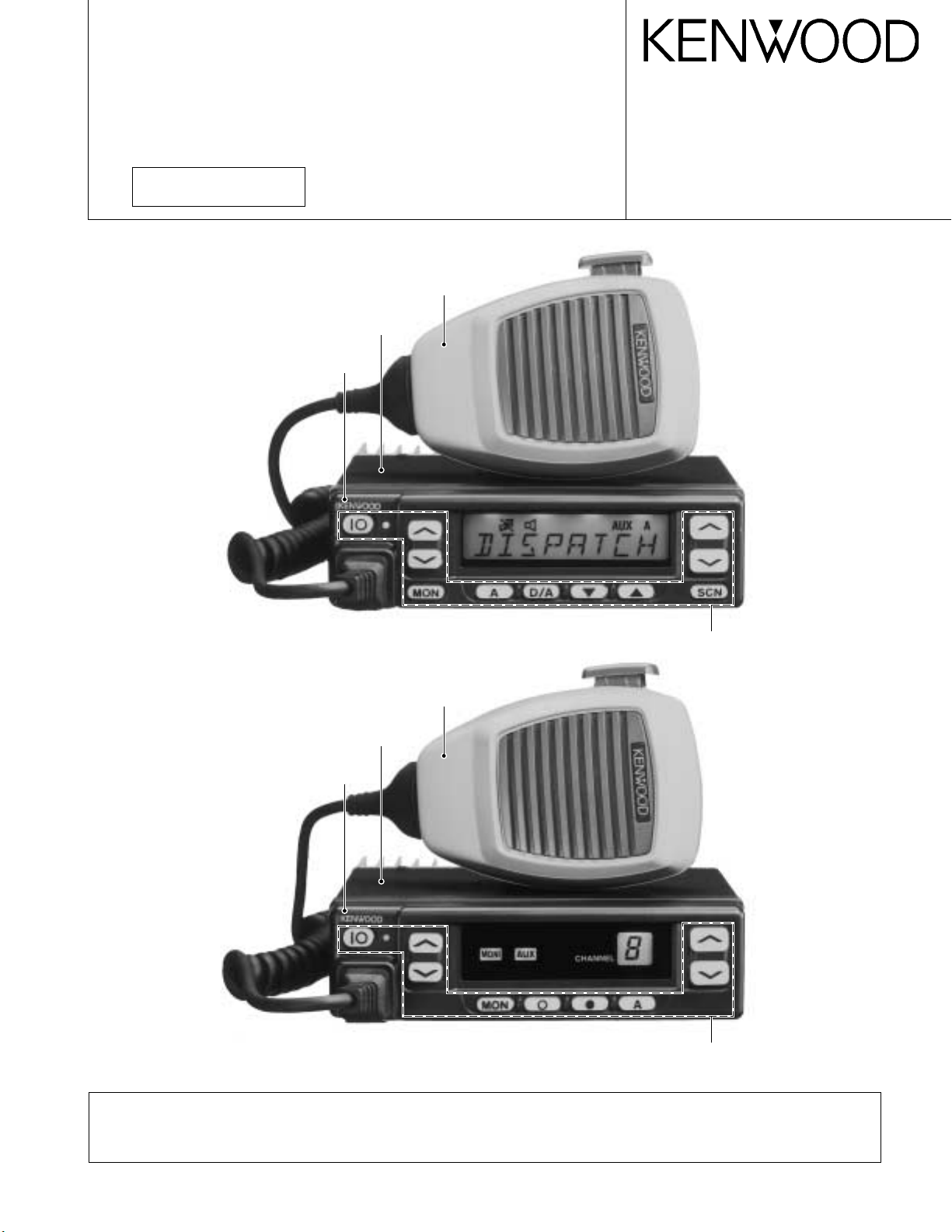
TK-760G (K)
© 2000-1 PRINTED IN JAPAN
B51-8497-10 (N) 1269
Microphone
(T91-0597-15)
Cabinet (Upper)
(A01-2165-13)
Panel assy
(A62-0642-03)
TK-762G (K)
Key top
(K29-5343-02)
Microphone
(T91-0597-15)
Cabinet (Upper)
(A01-2165-13)
Panel assy
(A62-0731-03)
Key top
(K29-5344-02)
Please use this manual in place of the service manual (preliminary version), B51-8497-00.
We have added the information on the circuit description, specifications, and K2 version specifications to the service
manual (preliminary version), B51-8497-00.

TK -760G/7 62G
CONTENTS / GENERAL
CONTENTS
GENERAL ……………………………………………………….. 2
SYSTEM SET-UP …………………………………………….. 4
OPERATING FEATURES ………………………………….. 5
REALIGNMENT……………………………………………… 10
INSTALLATION……………………………………………… 20
CIRCUIT DESCRIPTION………………………………….. 24
SEMICONDUCTOR DATA………………………………. 29
DESCRIPTION OF COMPONENTS ………………….. 31
PARTS LIST …………………………………………………… 33
EXPLODED VIEW ………………………………………….. 42
PACKING ………………………………………………………. 44
ADJUSTMENT ………………………………………………. 45
PC BOARD VIEWS
DISPLAY UNIT (X54-3270-10) : TK-760G …….. 54
DISPLAY UNIT (X54-3280-10) : TK-762G …….. 55
PLL/VCO (X58-4670-XX) ……………………………. 56
TX-RX UNIT (X57-5950-XX) (A/2) ………………. 57
TX-RX UNIT (X57-5950-XX) (B/2)……………….. 63
SCHEMATIC DIAGRAM …………………………………. 67
BLOCK DIAGRAM………………………………………….. 75
LEVEL DIAGRAM …………………………………………… 78
TERMINAL FUNCTION ………………………………….. 80
SPECIFICATIONS…………………………………………… 81
GENERAL
INTRODUCTION
SCOPE OF THIS MANUAL
This manual is intended for use by experienced technicians familiar with similar types of commercial grade communications equipment. It contains all required service information for the equipment and is current as of the publication date. Changes which may occur after publication are
covered by either Service Bulletins or Manual Revisions.
These are issued as required.
ORDERING REPLACEMENT PARTS
When ordering replacement parts or equipment information, the full part identification number should be included.
This applies to all parts : components, kits, or chassis. If the
part number is not known, include the chassis or kit number
of which it is a part, and a sufficient description of the required component for proper identification.
PERSONNEL SAFETY
The following precautions are recommended for personnel safety :
• DO NOT transmit if someone is within two feet (0.6
meter) of the antenna.
• DO NOT transmit until all RF connectors are verified se-
cure and any open connectors are properly terminated.
• SHUT OFF and DO NOT operate this equipment near
electrical blasting caps or in an explosive atmosphere.
• All equipment should be properly grounded before
power-up for safe operation.
• This equipment should be serviced by a qualified techni-
cian only.
PRE-INSTALLATION CONSIDERNATIONS
1. UNPACKING
Unpack the radio from its shipping container and check
for accessory items. If any item is missing, please contact
KENWOOD immediately.
2. LICENSING REQUIREMENTS
Federal regulations require a station license for each radio installation (mobile or base) be obtained by the equipment owner. The licensee is responsible for ensuring transmitter power, frequency, and deviation are within the limits
permitted by the station license.
Transmitter adjustments may be performed only by a licensed technician holding an FCC first, second or general
class commercial radiotelephone operator’s license. There
is no license required to install or operate the radio.
2
GENERAL
TK -7 60G /7 62G
3. PRE-INSTALLATION CHECKOUT
3-1. Introduction
Each radio is adjusted and tested before shipment. However, it is recommended that receiver and transmitter operation be checked for proper operation before installation.
3-2. Testing
The radio should be tested complete with all cabling and
accessories as they will be connected in the final installation. Transmitter frequency, deviation, and power output
should be checked, as should receiver sensitivity, squelch
operation, and audio output. Signalling equipment operation
should be verified.
4. PLANNING THE INSTALLATION
4-1. General
Inspect the vehicle and determine how and where the
radio antenna and accessories will be mounted.
Plan cable runs for protection against pinching or crushing wiring, and radio installation to prevent overheating.
4-2. Antenna
The favored location for an antenna is in the center of a
large, flat conductive area, usually at the roof center. The
trunk lid is preferred, bond the trunk lid and vehicle chassis
using ground straps to ensure the lid is at chassis ground.
4-3. Radio
The universal mount bracket allows the radio to be
mounted in a variety of ways. Be sure the mounting surface
is adequate to support the radio’s weight. Allow sufficient
space around the radio for air cooling. Position the radio
close enough to the vehicle operator to permit easy access
to the controls when driving.
4-4. DC Power and wiring
1. This radio may be installed in negative ground electrical
systems only. Reverse polarity will cause the cable fuse
to blow. Check the vehicle ground polarity before installa-
tion to prevent wasted time and effort.
2. Connect the positive power lead directly to the vehicle
battery positive terminal. Connecting the Positive lead to
any other positive voltage source in the vehicle is not rec-
ommended.
3. Connect the ground lead directly to the battery negative
terminal.
4. The cable provided with the radio is sufficient to handle
the maximum radio current demand. If the cable must be
extended, be sure the additional wire is sufficient for the
current to be carried and length of the added lead.
5. INSTALLATION PLANNING – CONTROL STATIONS
5-1. Antenna system
Control station. The antenna system selection depends
on many factors and is beyond the scope of this manual.
Your KENWOOD dealer can help you select an antenna system that will best serve your particular needs.
5-2. Radio location
Select a convenient location for your control station radio
which is as close as practical to the antenna cable entry
point. Secondly, use your system’s power supply (which
supplies the voltage and current required for your system).
Make sure sufficient air can flow around the radio and power
supply to allow adequate cooling.
SERVICE
This radio is designed for easy servicing. Refer to the
schematic diagrams, printed circuit board views, and alignment procedures contained in this manual.
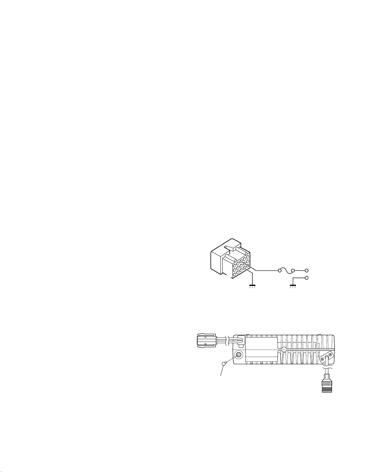
Note
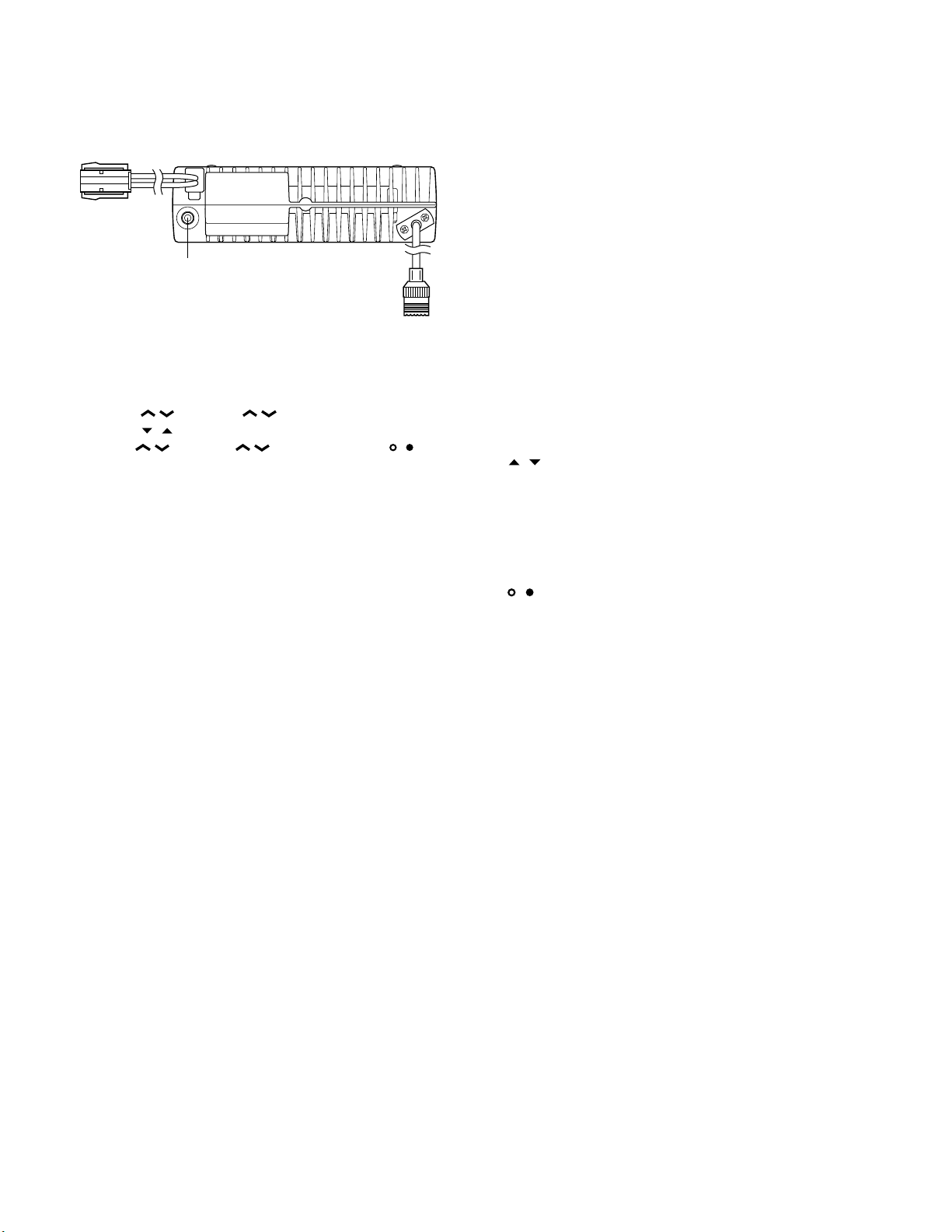
When you modify your radio as described in system setup, take the following precaution.
The rating of pin 7 (SB) of the accessory connector cable
(KCT-19) on the rear of the radio is 13.6V (1A). Insert a 1A
fuse if you use the SB pin for external equipment.
Accessory connector
cable (KCT-19)
1
7
13
15
If you do not intend to use the 3.5-mm jack for the external speaker, fit the supplied speaker-jack cap (B09-0235-05)
to stop dust and sand getting in.
Speaker-jack cap
(B09-0235-05)
3
6
+
–
3
TK -760G/7 62G
SYSTEM SET-UP
Merchandise received
License and frequency allocated by FCC
Choose the type of transceiver
Transceiver programming (Option)
Are you using the public address?
NO
Are you using the KGP-1A Modem GPS receiver
or the KGP-1B Modem GPS controller?
NO
Are you using the external speaker?
NO
Are you using ignition sense cable?
NO
128ch models
TK-760G
8ch models
TK-762G
See page 11.
A personal computer (IBM PC or compatible), programming interface (KPG-22),
and programming software (KPG-56D) are required for programming.
(The frequency and signalling (option) data are programmed for the transceiver.)
YES
YES
YES
*
KAP-1
PA/HA unit
KCT-20
Connection cable
KES-3
External speaker
*
Accessory connector cable
YES
KCT-19
Frequency range (MHz)
148~174
136~162
146~174
Frequency range (MHz)
148~174
136~162
See page 22.
Installation the TX-RX unit when used KAP-1.
(Option)
See the KCT-20 instruction manual
(B62-0733-11).
(Option)
See page 23.
(Option)
See page 20.
Ignition sense cable
(Option) (Option)
RF power
25W
25W
25W
RF power
25W
25W
See page 21.
KCT-18
Type
K
K2
M
Type
K
K2
Delivery
: You can install either KCT-19 or KCT-20 to the
*
TK-760G/762G transceiver
4
TK -7 60G /7 62G
OPERATING FEATURES
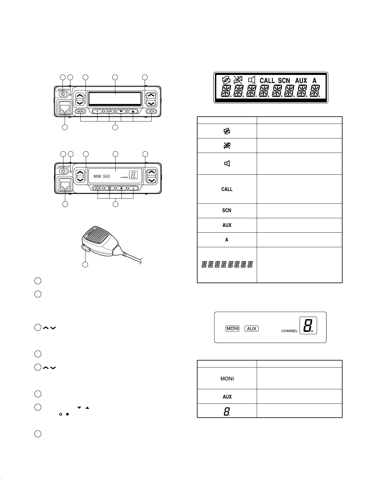
1. Controls and Functions
1-1. TK-760G Front Panel
1 2 3 4 5
76
1-2. TK-762G Front Panel
1 2 3 4 5
76
1-3. Microphone
8
1
IO (Power) switch
Press to switch the transceiver ON (or OFF).
2
LED indicator
Lights red while transmitting. Lights green while receiving. Flashes orange while receiving a Code Squelch or
Selective Call code, or a 2-Tone code that matches the
one set up in your transceiver.
/ keys
3
These are PF (Programmable Function) keys. Press each
key to activate its auxiliary function. The default settings
are Volume Up and Volume Down.
4
Display
See right.
5
/ keys
These are PF (Programmable Function) keys. Press each
key to activate its auxiliary function. The default settings
are Channel Up and Channel Down.
Microphone jack
6
Insert the microphone plug into this connector.
MON, A, D/A,
7
MON,
These are PF (Programmable Function) keys. Press each
key to activate its auxiliary function.
PTT (Push-to-Talk) switch
8
Press this switch, then speak into the microphone to call
a station.
, , and A keys (TK-762G)
, , and SCN keys (TK-760G)
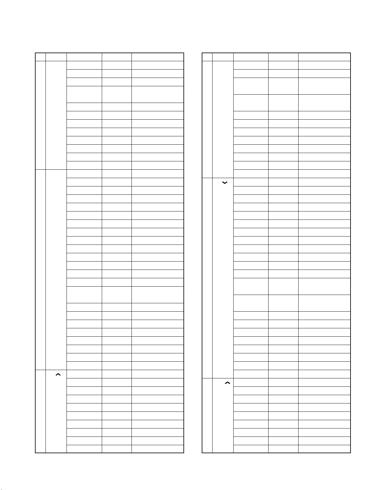
1-4. Display
■ TK-760G
Indicator Description
Appears while using SmarTrunk.
Appears when the selected channel
in busy.
Appears when QT, DQT, DTMF, or
2-Tone decoding is deactivated (by
pressing the Monitor key).
Appears when you receive a Code
Squelch, Selective Call, 2-Tone code.
Also appears when you transmit
using Code Squelch or Selective Call.
Appears while scanning.
Appears when the AUX port is
activated.
Appears when the selected channel
is included in the scanning sequence.
Displays the selected channel
number (or name), DTMF digits
(when entering digits, confirming
digits, or making a call), and mes-
sages received via Selective Call.
■ TK-762G
Indicator Description
Appears when QT, DQT, DTMF, or
2-Tone decoding is deactivated (by
pressing the Monitor key).
Appears when the AUX port is
activated.
Displays the selected channel
number.
5
TK-760G/762G
OPERATING FEATURES
1-5. Rear panel
Power input
connector
External
speaker jack
Antenna
connector
1-6. Programmable Auxiliary Functions
The following keys can be programmed with the functions listed below.
TK-760G :
TK-762G :
• AUX
• Channel Down
• Channel Up
• Display Character (TK-760G only)
• Emergency *
• Group Down (TK-760G only)
• Group Up (TK-760G only)
• Home Channel
• Horn Alert
• Key Lock
• Monitor A (Monitor Unmute-Momentary)
• Monitor B (Monitor Unmute-Toggle)
• Monitor C (Carrier Squelch-Momentary)
• Monitor D (Carrier Squelch-Toggle)
• None (No function)
• Operator Selectable Tone *
• Public Address
• Redial
• Scan (TK-760G only)
• Scan Del/Add (TK-760G only)
• Selectable QT *
• Talk-Around
• Volume Up
• Volume Down
• 2-Tone Encode Select *
*1 : This function can be used only with a foot switch.
*2 : This function is available for K market models only.
*3 : This function is available for M market models only.
*4 : The code for the TK-762G transceiver is not selectable.
You can transmit only one 2-Tone code, which is preprogrammed in the transceiver.
/ (left side), / (right side), MON, A, D/A,
, , and SCN.
/ (left side), / (right side), MON, , , and
A.
1
2
(TK-760G only)
3
(TK-760G only)
4
2.Operation Features
The TK-760G/762G is a VHF FM radio designed to operate in conventional format. The programmable features are
summarized.
3.Transceiver Controls and Indicators
3-1. Front Panel Controls
All the keys on the front panel are momentary-type push
buttons. The functions of these keys are explained below.
• POWER key
Transceiver POWER key. When the power is switched
off, all the parameters are stored in memory. When the
power is switched on again, the transceiver returns to the
previous conditions.
• CHANNEL UP/DOWN key (Programmable)
• / key (Programmable) : TK-760G only
• SCAN key (Programmable) : TK-760G only
• MONITOR key (Programmable)
• A, D/A key (Programmable) : TK-760G only
• , , A key (Programmable) : TK-762G only
• VOLUME UP/DOWN key (Programmable)
• BUSY/TX LED
The BUSY indicator (Green LED) shows that the channel
is in use. The TX indicator (Red LED) shows that you are
transmitting.
3-2. Programmable Keys
The FPU (KPG-56D) enables programmable keys to select the following functions.
AUX, Channel down, Channel up, Display character *
Emergency (Only foot key ; M type only), Group down *
Group up *
Monitor B, Monitor C, Monitor D, Operator selectable tone
(K type only), Public address, Redial, Scan *
1
*
, Talk around, Volume down, Volume up and None.
These functions the FPU programs to the functionkeys
and described in the following sections.
*1 : TK-760G only.
• AUX
If this key is pressed, «AUX» icon lights on the display and
AUX port which is inside of the transceiver turns to the high
level. If pressed again, the «AUX» icon goes off and the AUX
ports turns to the lower level.
1
, Home channel, Horn alert, Key lock, Monitor A,
1
, Scan del/add
1
,
1
,
• Channel up/down
When the key is pressed each time, the channel number
to be selected is incremented/decremented and repeats if
held for one second or longer.
6

TK -7 60G /7 62G
OPERATING FEATURES
• Display character (TK-760G only)
This key switches the LCD display between the group
and channel number and the group and channel name.
• Emergency (M market models only)
Pressing this key for longer than 1 second causes the
transceiver to enter the emergency mode. The transceiver
jumps to the programmed «Emergency the group and channel» and transmits for 25 seconds.
The transceiver disables mic mute while transmitting.
After finishing transmission, the transceiver receivers for 5
seconds. The transceiver mutes the speaker while receiving. Following the above sequence, the transceiver continues to transmit and receive.
• Group up/down (TK-760G only)
When the key is pressed each time, the group number to
be selected is incremented/decremented and repeats if held
for one second or longer.
• Home channel
Press this key once, the channel switches to the pre-programmed home channel.
• Horn alert
If you are called from the base station using 2-tone/DTMF
while you are away from your transceiver, you will be
alerted by the vehicle horn or some other type of external
alert. To turn the horn alert function on , press this key. A
confirmation tone sounds, (and the display shows «HA» on
the LCD *
turned off.
1
).
If this key is pressed again, the horn alert function is
*1 : TK-760G only.
• Key lock
Pressing this key causes the transceiver to accept entry
of only the [Vol Up/Down], [Key lock], [PTT], [Monitor A],
[Monitor B], [Monitor C], [Monitor D], and [Emergency] keys.
• Monitor
Used to release signalling or squelch when operating as a
conventional. It is also used to reset option signalling.
• Operator selectable tone (K market models only)
This key switches the pre-set decode QT/DQT and encode QT/DQT to OST (Operator Selectable Tone) tone pair.
Press this key, the transceiver enters to OST select
mode. In this mode, the display shows «OFF» and the operator can select one of the OST tone pair using the channel up/
down key. The display shows «TONE
is selected.
**
Press OST key again, the transceiver exits from the OST
select mode.
16 kinds of tone pair for OST can be programmed by
KPG-56D. OST is useful to access the repeater with same
radio frequency and different tone (QT/DQT).
» and tone pair No.
**
• Public address
Public address amplifies the microphone audio, and outputs it through a PA speaker. PA is activated by pressing
this key. A confirmation tone sounds, (and the display
shows «PA» *
non-scanning).
The RADIO continues to scan & receive calls while in PA
mode. Pressing PTT activates PA, and will override an incoming call at anytime; however, no RADIO transmission
takes place.
If this key is pressed again, a confirmation tone will
sound, (the display will return to the normal channel or
SCAN display *
*1 : TK-760G only.
1
). PA can be activated at anytime (scanning or
1
), and the PA function will turn off.
• Redial
If you press this key when the group/channel is displayed, the last transmitted DTMF code will appear on the
display. Pressing the PTT switch at this time will transmit
the displayed DTMF code.
• Scan (TK-760G only)
Press this key starts scanning. Pressing this key stops
scanning.
• Scan del/add (TK-760G only)
This key switches the currently displayed channel between «Delete» and «Add».
The «Add» channel contained in the scan sequence, and
«Delete» channel is not contained. In the scan mode, this
key switches the channnel delete or add temporarily.
• Talk around
Press this key, the transceiver uses the receive frequency and the tone for transmission.
The operator can call the other party directory (without
repeater). Press this key again, the talk around function
goes off.
• Volume up/down
When the key is pressed, the volume level is increased/
decreased and repeats if held for 200ms or longer.
• None
Sounds error operation beep, and no action will occur.
Use this function when the transceiver is required to be
more simple operated.
4. Scan Operating (TK-760G only)
■ Scan types
• Single group scan
You can scan all valid (ADD) channels in the displayed
group that can be selected with the group up/down key.
• Multiple group scan
You can scan all valid (ADD) channels in the all valid
(ADD) group.
7

TK -760G/7 62G
OPERATING FEATURES
■ SCAN start condition
One or more non-priority channels must be added to all
channels that can be scanned. The transceiver must be in
normal receive mode (PTT off).
When you activate the key programmed to the scan function, the scan starts. The scan icon «SCN» lights and «SCAN»
is indicated on alphanumeric display.
■ Scan stop condition
The scan stops temporarily if the following conditions are
satisfied.
1) A carrier is detected, then signalling matches on chan-
nels for which receive the signalling is set by the pro-
gramming software.
2) A carrier is detected on the channels for which receiving
signalling is not set by the programming software or
when the monitor (signalling cancel) function is activated.
■ Scan channel types
1) Priority channel is the most important channel for the
scan, and always detects a signal during scan and when
the scan stops temporarily.
2) Non-priority channels detects a signal during scan. For
the channels that can be selected with the group or chan-
nel up/down key when the scan does not occur, adds an
indicator «A» lights.
■ Priority channel setting
A priority channel can be set as follows with the programming software (KPG-56D).
1) Specify a priority channel as a fixed priority channel.
2) Make a selected channel, a priority channel.
3) Selected channel
The transceiver reverts to the channel before scanning or
the channel that you changed during scan.
4) Last called channel
The transceiver reverts to the last called channel during
the scan.
5) Last used channel
The transceiver reverts to the last used (transmitted)
channel during scan. «Last used» revert channel includes
talkback function.
6) Selected with talkback
The transceiver reverts to the channel before scanning or
the channel that you changed during scan.
■ Scan end
When you reactivate the key programmed to the scan
function during scan mode, the scan ends.
The scan icon «SCN» and «SCAN» display goes off.
■ Temporarily delete/add
It is possible to delete or add channel temporarily during
scan. When scan stops on unnecessary channel for example by interference of the other party, activate the delete/
add function (for example press the key), then that channel
is deleted temporarily and scan re-start immediately.
When you would like to add the deleted channel tempo-
rarily to scan sequence, select the desired (deleted) channel
during scan, activate the delete/add function (for example
press the key) before scan re-start.
That channel is added temporarily to scan sequence. The
temporary deleted or added channels are returns to pre-set
delete/add, when the transceiver exits from scan mode.
■ Scan type according to the priority channel
1) When no priority channel is set : Only the non-priority
channels are scanned.
If a non-priority channel stops temporarily, it stops until
there is no signal on the channel.
2) When priority channel is set : Either priority channel is
scanned.
If a non-priority channel stops temporarily, a priority channel signal is detected at certain intervals.
If a priority channel stops temporarily, it stops until there
is no signal on the priority channel.
■ Revert channel
The revert channel is used to transmit during scanning
and set by the programming software (KPG-56D).
1) Priority
The transceiver reverts to the priority channel.
2) Priority with talkback
The transceiver reverts to the priority channel.
If you press PTT during a resume timer (dropout delay
time, TX dwell time) or calling, you can transmit on current channel to answer to the call however revert channel
is set to priority channel.
After resume time, scan re-starts and transmission channel is return to priority channel.
5. Details of Features
■ Time-out timer
The time-out timer can be programmed in 15 seconds
increments from 15 seconds to ten minutes. If the transmitter is keyed continuously for longer than the programmed
time, the transmitter is disabled and a warning tone sounds
while the PTT button is held down. The alert tone stops
when the PTT button is released.
■ PTT ID
PTT ID provides a DTMF ANI to be sent with every time
PTT (beginning of transmission, end of transmission, or
both).
You can program PTT ID «on» or «off» for each group. The
contents of ID are programmed for each channel.
The timing that the transceiver sends ID is programmable.
BOT : DTMF ID (BOT)/MSK ID is sent on beginning of
transmission.
EOT : DTMF ID (EOT)/MSK ID is sent on end of transmis-
sion.
Both : DTMF ID (BOT)/MSK ID is sent on beginning of
transmission and DTMF ID (EOT)/MSK ID is sent on end
of transmission.
8

TK -7 60G /7 62G
OPERATING FEATURES
■ Off hook decode
If the Off hook decode function has been enabled, removing and replacing the microphone on the hook has no
effect for decoding QT/DQT and option signalling.
■ «TOT» pre-alert
The transceiver has «TOT pre-alert timer. This parameter
selects the time at which the transceiver generates «TOT»
pre-alert tone before «TOT» is expired.
«TOT» will be expired when the selected time passes
from a TOT pre-alert tone.
■ «TOT» re-key time
The transceiver has «TOT» re-key timer. This timer is the
time you can not transmit after «TOT» exceeded. After «TOT»
re-key time expired you can transmit again.
■ «TOT» reset time
The transceiver has «TOT» reset timer. This timer is the
minimum wait time allowed during a transmission that will
reset the «TOT» count.
«TOT» reset time causes the «TOT» to continue even after
PTT is released unless the «TOT» reset timer has expired.
■ OST (Operator Selectable Tone)
(TK-760G K market models only)
The transceiver is capable to have «OST» function and 16
tone pair (QT/DQT).
■ Clear to transpond
The transceiver waits the transpond of 2-tone /DTMF if
channel is busy until channel open. This feature prevents
the interference to other party.
■ AND/OR
You can select AND or OR for option signalling match
conditions.
Alert/Transpond
AND QT/DQT+DTMF (2-tone); Option matches = Action
OR QT/DQT+DTMF (2-tone); Option matches = Action
AF mute open
AND QT/DQT+DTMF (2-tone); Option matches = Action
OR QT/DQT/ID; Signalling only matches = Action
With OR set up, alert/transpond will not function with
only DTMF.
With OR set up, AF mute will not release when only
DTMF matches.
With a conventional channel not set up with QT or DQT,
only the carrier is considered when signalling matches.
■ Auto Reset
If option signalling matches a group set up with option
signalling, option signalling is released. After matching option signalling, option signalling will temporarily reset automatically.
■ Dead Beat Disable
If the D.B.D. code matches, a predetermined action will
occur. Whether option signalling is activated or not, when
D.B.D. matches on any channel, the transceiver will become
TX inhibited or TX/RX inhibited. While D.B.D. is active, if the
D.B.D. code + «#» code is received, D.B.D. will disactivate.
When D.B.D. matches, transpond will function. Alert will
not be output, and option signalling match icon will not appear.
6. Option Signalling (DTMF/2-Tone)
Built-in DTMF decoder is available for option signalling.
Built-in 2-tone decoder is available for option signalling.
It is possible to use individual call, group call, D.B.D.
(Dead Beat Disable). D.B.D. is used with DTMF only.
If the option signalling matches, a predetermined action
will occur.
If option signalling matches on a group/channel which is
set up with option signalling, the option signalling indicator
(CALL) will flash and option signalling will be released. The
transpond or alert tone will sound.
The orange LED will flash.
While option signalling matches (or if option signalling is
deactivated when you are transmitting), you can mute or
unmute QT/DQT/Carrier.
7. Audible User Feedback Tones
The transceiver outputs various combinations of tones to
notify the user of the transceiver operating state. The main
tones are listed below.
The high tone is 1477Hz, the mid tone is 941Hz, and the
low tone is 770Hz.
■ Power on tone
This tone is output when the transceiver is turned on.
(The high tone is output for 500ms.)
■ Alert tone
This tone is output when the transceiver is TX inhibition
for TOT, and PLL unlocked. It is output until the PTT button
is released.
■ DBD on tone
When a D.B.D. code is received, transpond tone sounds.
■ DBD off tone
When a D.B.D. release code is received, transpond tone
sounds.
9
TK -760G/7 62G
User mode
Panel test mode
(TK-760G only)
PC mode
Firmware programming mode
Panel tuning mode
Data programming mode
PC test mode
PC tuning mode
Self programming
mode (TK-760G only)
Check sum
Clone mode
OPERATING FEATURES / REALIGNMENT
■ Busy tone
Sounds in conventional mode, when busy channel lockout is functioning. You can select yes or no for the optional
feature’s warning tone.
■ Group call tone
Sounds when a group call with the correct DTMF/2-tone
option signalling is received, repeats 7 times. You can select yes or no for the optional feature’s warning tone.
■ Individual call tone
Sounds when an individual call with the correct DTMF/2tone option signalling is received. You can select yes or no
for the optional feature’s warning tone.
■ Key press tone [A]
Sounds when a key is pressed. For toggle keys, sounds
when toggle function is turned on (key press tone [B]
sounds when it is turned off). You can select yes or no for
the optional feature’s control tone.
■ Key press tone [B]
Sounds when a key is pressed. For toggle keys, sounds
when the toggle function is turned off (key press tone [A]
sounds when it is turned on). You can select yes or no for
the optional feature’s control tone.
■ Key input error tone
Sounds when a key is pressed but that key cannot be
used. You can select yes or no for the optional feature’s
warning tone.
■ Roll over tone
Sounds in Conventional format at the smallest group/
channel. You can select yes or no for the optional feature’s
control tone.
REALIGNMENT
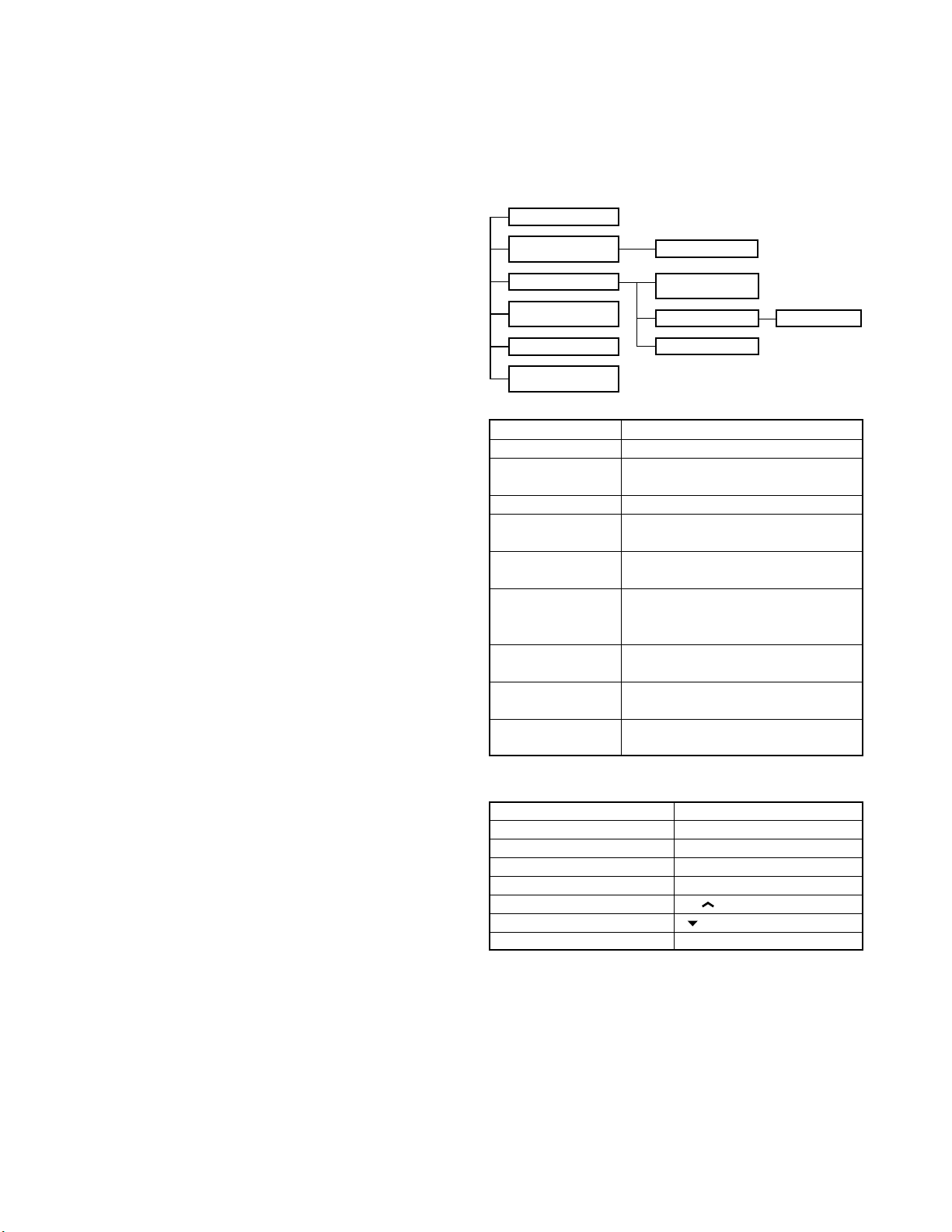
1. Modes
Mode Function
User mode For normal use.
Panel test mode Used by the dealer to check the funda-
ment characteristics.
Panel tuning mode Used by the dealer to tune the radio.
PC mode Used for communication between the
radio and PC (IBM compatible).
Data programming Used to read and write frequency data
mode and other features to and from the radio.
PC test mode Used to check the radio using the PC.
This feature is included in the FPU.
See panel tuning.
Firmware program- Used when changing the main program
ming mode of the flash memory.
Clone mode Used to transfer programming data from
one radio to another.
Self programming Frequency, signalling and features write
mode to the radio.
■ Transpond tone
Sounds when an individual call with the correct DTMF/2tone option signalling is received. For group calls, only the
group tone will sound, not the transpond tone.
■ Pre alert tone
Sounds prior to the TOT TX inhibit activation. If TOT pre
alert is set, the tone sounds at the amount of time programmed, before the TOT expires (TOT time – TOT pre alert
time = Pre alert tone sounding time). You can select yes or
no for the optional feature’s warning tone.
10
2. How to Enter Each Mode
Mode Operation
User mode Power ON
Panel test mode
PC mode Received commands from PC
Panel tuning mode [Panel test mode]+[SCN]
Firmware programming mode
Clone mode [ ]+Power ON (Two seconds)
Self programming mode [A]+Power ON (Two seconds)
[SCN]+Power ON (Two seconds)
[CH ]+Power ON (Two seconds)
3. For the Panel Test Mode (TK-760G only)
Setting method refer to ADJUSTMENT.
3-1. For the Panel Tunning Mode
Setting method refer to ADJUSTMENT.
REALIGNMENT
TK -7 60G /7 62G
4. Check Sum
Executing this function, «TUNING» apears on the display
of the TK-760G while calculation the check sum.
When the calculation is completed, the display returns to
normal and PC displays the check sum of the radio.
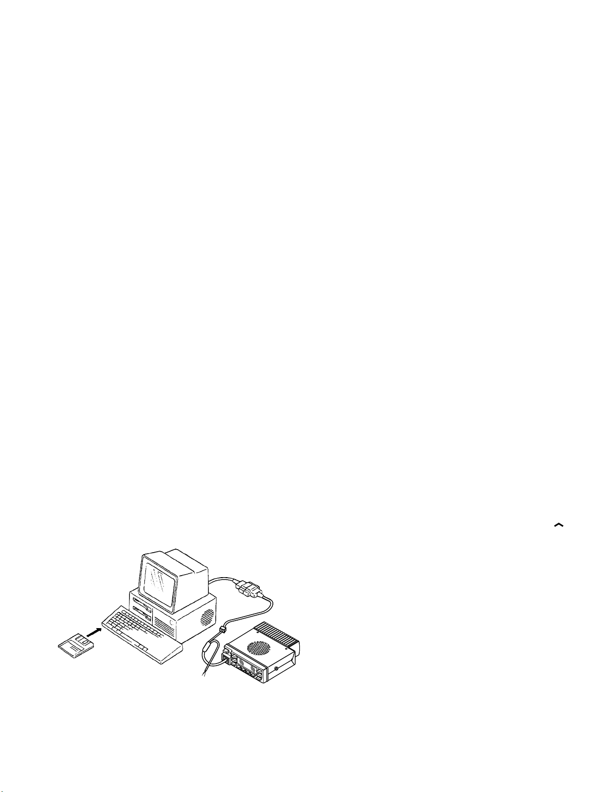
5. PC Mode
5-1. Preface
The TK-760G/762G transceiver is programmed using a
personal computer, a programming interface (KPG-46) and
programming software (KPG-56D).
The programming software can be used with an IBM PC
or compatible. Figure 1 shows the setup of an IBM PC for
programming.
5-2. Connection Procedure
1. Connect the TK-760G/762G to the personal computer
with the interface cable.
2. When the Power is switched on, user mode can be en-
tered immediately. When the PC sends a command, the
radio enters PC mode.
When data is transmitted from transceiver, the red LED
blink.
When data is received by the transceiver, the green LED
blink.
Notes :
• The data stored in the personal computer must match
model type when it is written into the flash memory.
• Change the TK-760G/762G to PC mode, then attach the
interface cable.
5-3. KPG-46 Description
(PC programming interface cable : Option)
The KPG-46 is required to interface the TK-760G/762G to
the computer. It has a circuit in its D-subconnector (25-pin)
case that converts the RS-232C logic level to the TTL level.
The KPG-46 connects the modular microphone jack of
the TK-760G/762G to the computers RS-232C serial port.
KPG-46
IBM-PC
KPG-56D
TK-760G/762G
Fig. 1
5-4. Programming Software Description
The KPG-56D programming disk is supplied in 3-1/2″ disk
format. The software on this disk allows a user to program
TK-760G/762G radio via a programming interface cable
(KPG-46).
5-5. Programming With IBM PC
If data is transferred to the transceiver from an IBM PC
with the KPG-56D, the destination data (basic radio information) for each set can be modified. Normally, it is not necessary to modify the destination data because their values are
determined automatically when the frequency range (frequency type) is set.
The values should be modified only if necessary. Data
can be programmed into the flash memory in RS-232C format via the modular microphone jack.
6. Firmware Programming Mode
6-1. Preface
Flash memory is mounted on the TK-760G/762G. This
allows the TK-760G/762G to be upgraded when new features are released in the future. (For details on how to obtain the firmware, contact Customer Service.)
6-2. Connection Procedure
Connect the TK-760G/762G to the personal computer
(IBM PC or compatible) with the interface cable (KPG-46).
(Connection is the same as in the PC Mode.)
6-3. Programming
1. Start up the programming software (KPG-56D), select
«firmware program» in the «Program» item, and press the
Return key on your personal computer. This starts up the
firmware programmer.
2. The top screen is displayed. Press any key to advance to
the next screen.
3. Set the communications speed (normally, 57600 bps)
and communications port in the Setup item.
4. Set the firmware to be updated by File select (=F1).
5. Turn the TK-760G/762G Power ON with the [CH
switch held down. Hold the switch down for two sec-
onds until the display changes to «PROG 576», the BUSY/
TX LED lights orange. When «PROG 576» appears, re-
lease your finger from the switch.
6. Check the connection between the TK-760G/762G and
the personal computer, and make sure that the TK-760G/
762G is in Program mode.
7. Press F10 on the personal computer. A window opens
on the display to indicate the writing progress. When the
TK-760G/762G starts to receive data, the BUSY/TX LED
lights green.
8. If writing ends successfully, the LED on the TK-760G/
762G goes off and the checksum is displayed.
(Since the TK-762G does not have a display, check the
checksum with the FPU (KPG-56D).)
9. If you want to continue programming other TK-760G/
762G, repeat steps 5 to 8.
]
11
TK -760G/7 62G
MBL
PSB
GND
PTT/TXD
ME
MIC
HOOK/RXD
CM
GND
REMOTE/TXD
PTT/RXD
8
1
1
8
REALIGNMENT
Notes :
• To start the Firmware Programmer from KPG-56D, the
FPRO path must be set up by the KPG-56D setup.
• This mode cannot be entered if the Firmware programming mode is set to Disable in the Programming software (KPG-56D).
• When programming the firmware, it is recommend to
copy the data from the floppy disk to your hard disk before you update the radio firmware.
Directly copying from the floppy disk to the radio may not
work because the access speed is too slow.
6-4. Function
1. If you press the [MON] switch while «PROG 576» is displayed, the checksum is displayed. If you press the
[MON] switch again (while the checksum is displayed),
«PROG 576» is redisplayed.
2. If you press the [A] switch while «PROG 576» is displayed,
the display changes to «PROG 192» to indicate that the
write speed is low speed (19200 bps). If you press the
[A] switch again while «PROG 192» is displayed, the display changes to «PROG 384», and the write speed becomes the middle speed (38400 bps). If you press the
[A] switch again while «PROG 384» is displayed, the display returns to «PROG 576».
Note :
TK-762G indicate
19200 bps : The LED flashes green and red alternately.
38400 bps : The LED flashes orange.
57600 bps : The LED lights orange.
Normally, write in the high-speed mode.
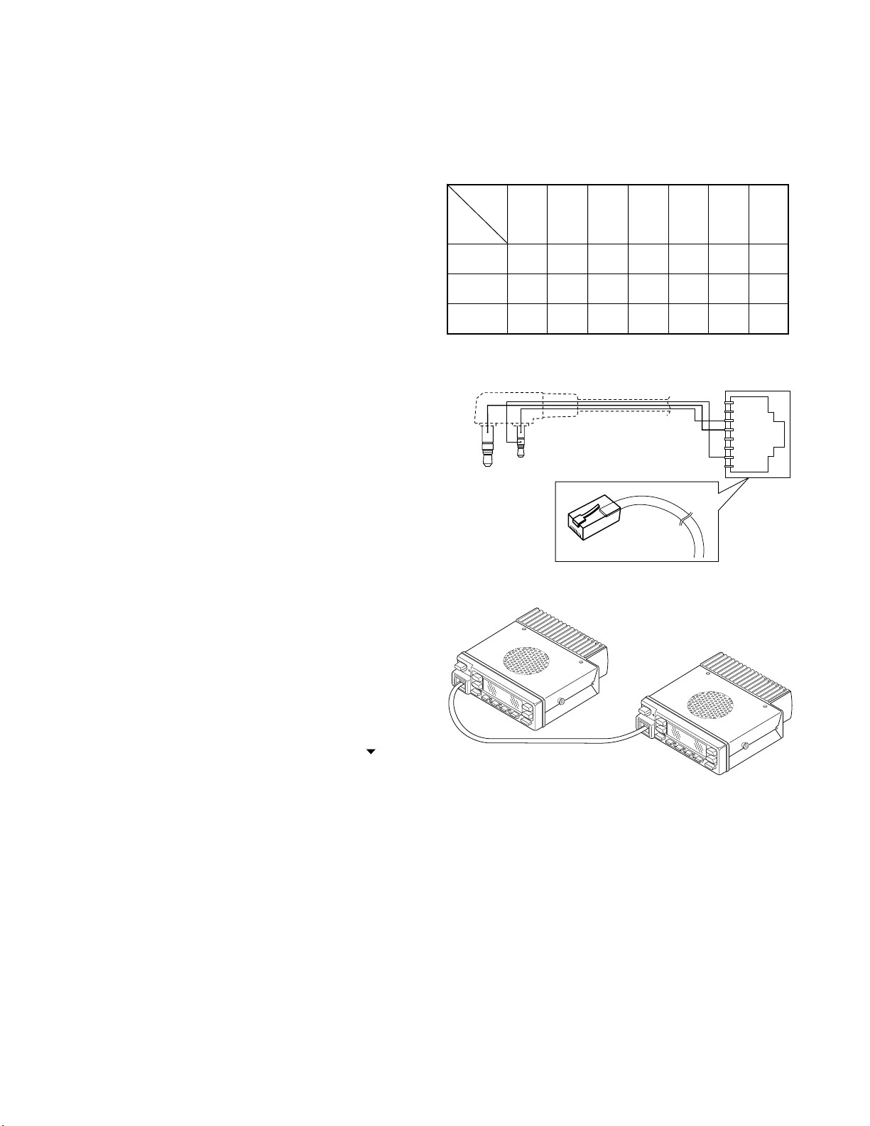
Note :
You can clone the programmed data between the trans-
ceiver listed below. Frequency version must be same.
Slave
Master K M K M K2 K2
TK-760G YES NO YES NO NO NO NO
TK-760G NO YES NO YES NO NO NO
TK-760G NO NO NO NO YES YES NO
TK-260G TK-260G TK-760G TK-760G TK-760G TK-260G TK-270G
KMKMK2K2M2
TK-270G TK-270G TK-762G TK-762G TK-762G TK-270G
K
M
K2
Clone cable
E30-3411-05 (TK-760G → TK-260G/270G)
7. Clone Mode
Programming data can be transferred from one radio to
another by connecting them via their modular microphone
jacks. The operation is as follows (the transmit radio is the
master and the receive radio is the slave).
1. Turn the master TK-760G power ON with the [
held down. The TK-760G displays «CLONE».
2. Power on the slave TK-760G/762G.
3. Connect the cloning cable (No. E30-3382-05) to the
modular microphone jacks on the master and slave.
4. Press the [SCN] key on the master while the master displays «CLONE». The data of the master is sent to the
slave. While the slave is receiving the data, «–PC–» is displayed. When cloning of data is completed, the master
displays «END», and the slave automatically operates in
the User mode. The slave can then be operated by the
same program as the master.
5. The other slave can be continuously cloned. When the
[SCN] key on the master is pressed while the master displays «END», the master displays «CLONE». Carry out the
operation in step 2 to 4.
] key
Cloning cable
(E30-3382-05)
Fig. 2
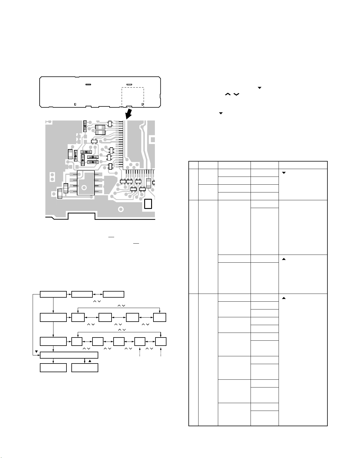
8. Self Programming Mode (TK-760G only)
Write mode for frequency data and signalling etc. Mainly
used by the person maintaining the user equipment.
8-1. Enter to the Self Programming Mode
Remove D507 (Figure 3) from the TX-RX unit. Hold down
the [A] key and turn the power switch on. When enter the
self programming mode, «SELF» is displayed. The mode
changes autoically to Model Select Mode in about one second, and set up radio type, radio band & channel type and
frequency version.
12
REALIGNMENT
TK -7 60G /7 62G
Note :
This mode (self programming mode) cannot be set when
it has been disabled with the FPU.
TX-RX unit B/2
Foil side
IC502
D507
D505
5
4
50
51
IC505
8
1
The silk screen of D505 and D507 is reversed on the TXRX unit PCB (Part No. J72-0677corrected from the next version, J72-0677-
02). this silk screen will be
12.
Fig. 3
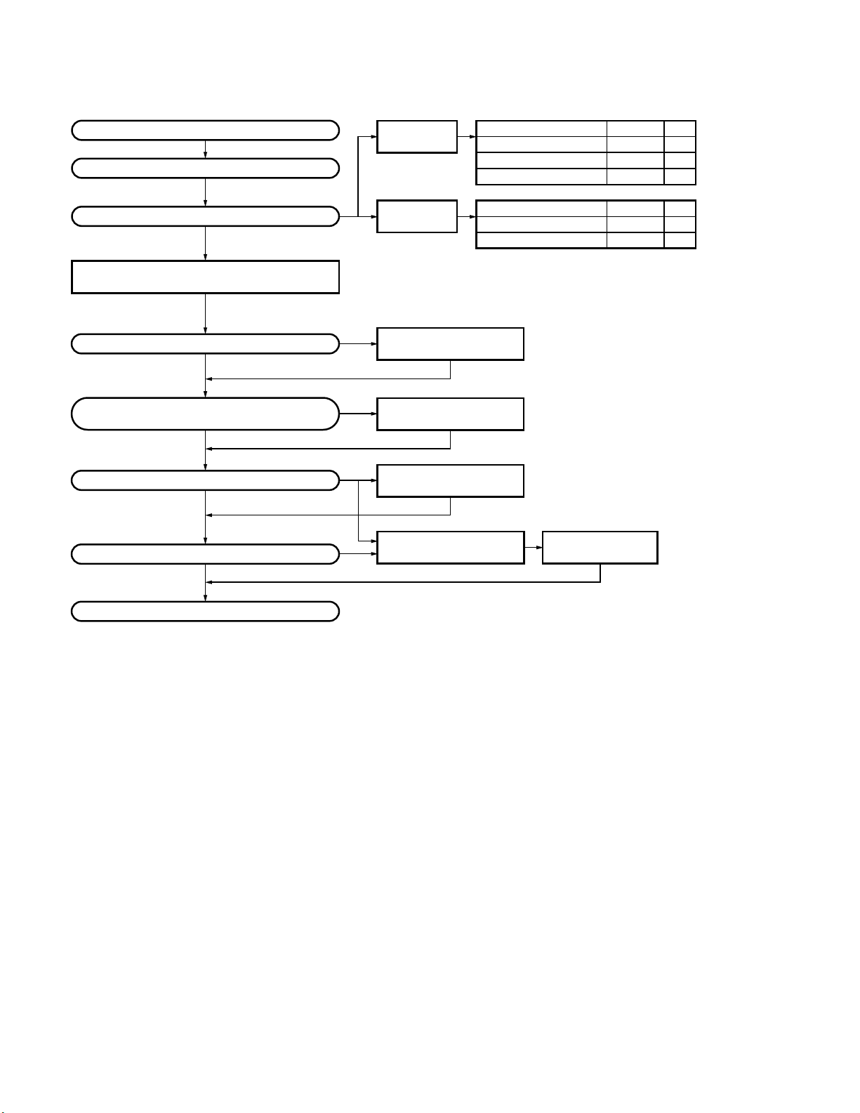
8-2. Model Select Mode
• Flow chart
Radio type
Radio band &
channel type
Frequency
version
[ ]
Self programming mode
Channel set
mode
**
[D/A]
[D/A]
[D/A]
[MON]
Portable
VHF
8CH
VHF
F1
Function set
[CH
/ ]
mode
[CH
/ ]
[ ]
[CH
/ ]
VHF
F2
VHF
128CH
[CH
/ ]
Mobile
[CH / ]
/ ]
[CH / ]
[CH
UHF
F1
UHF
8CH
[CH
/ ]
*
Cannot be
set when
portable is
UHF
F3
select.
[CH
/ ]
[CH
/ ]
*
Cannot be
UHF
128CH
UHF
F4
set when
mobile is
select.
Note :
If the radio type of TK-760G was temporally set to «Portable» for the cloning purposes, «UNPROG» is displayed (at
User mode) when the TK-760G is turned on.
In this case, please set the radio type back to «Mobile» at
model select mode menu.
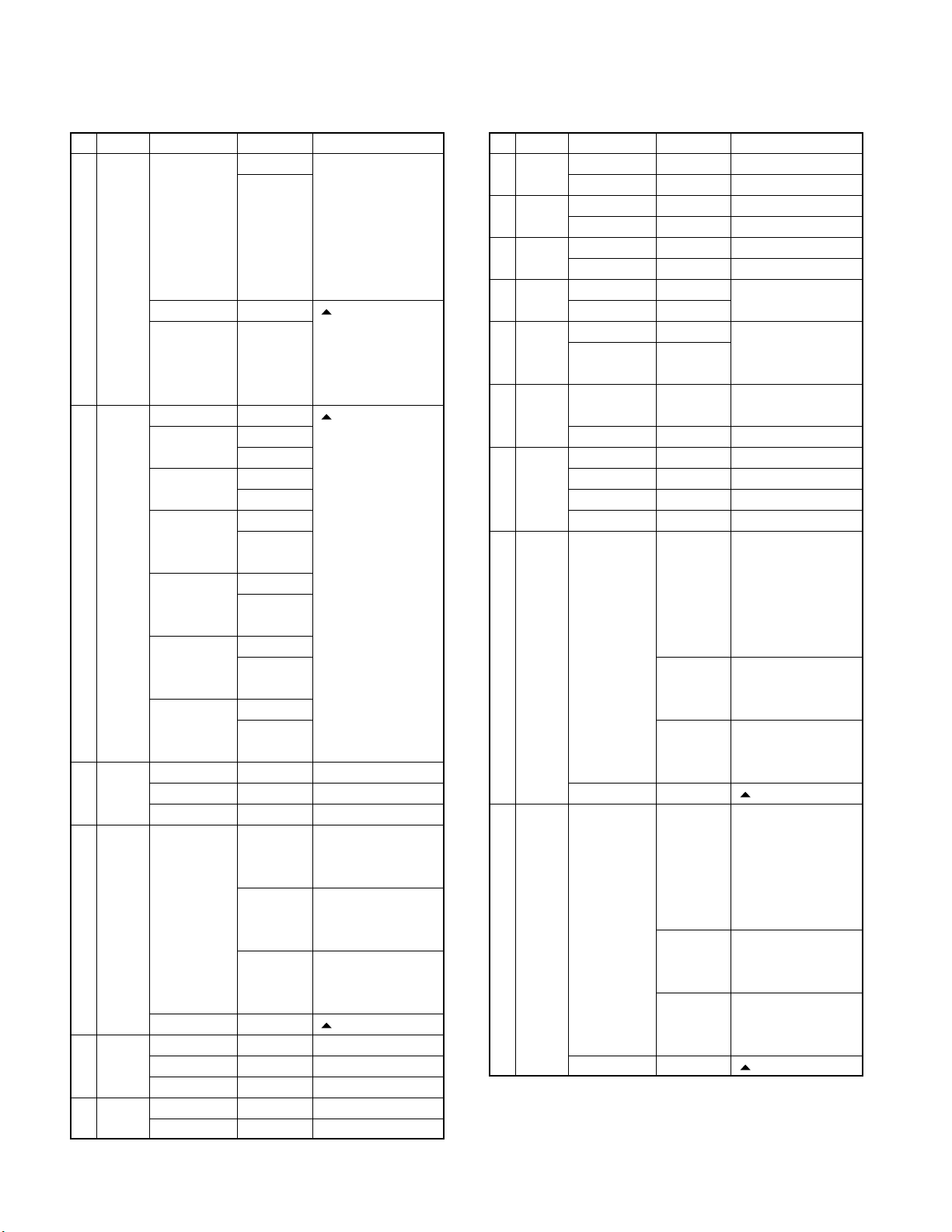
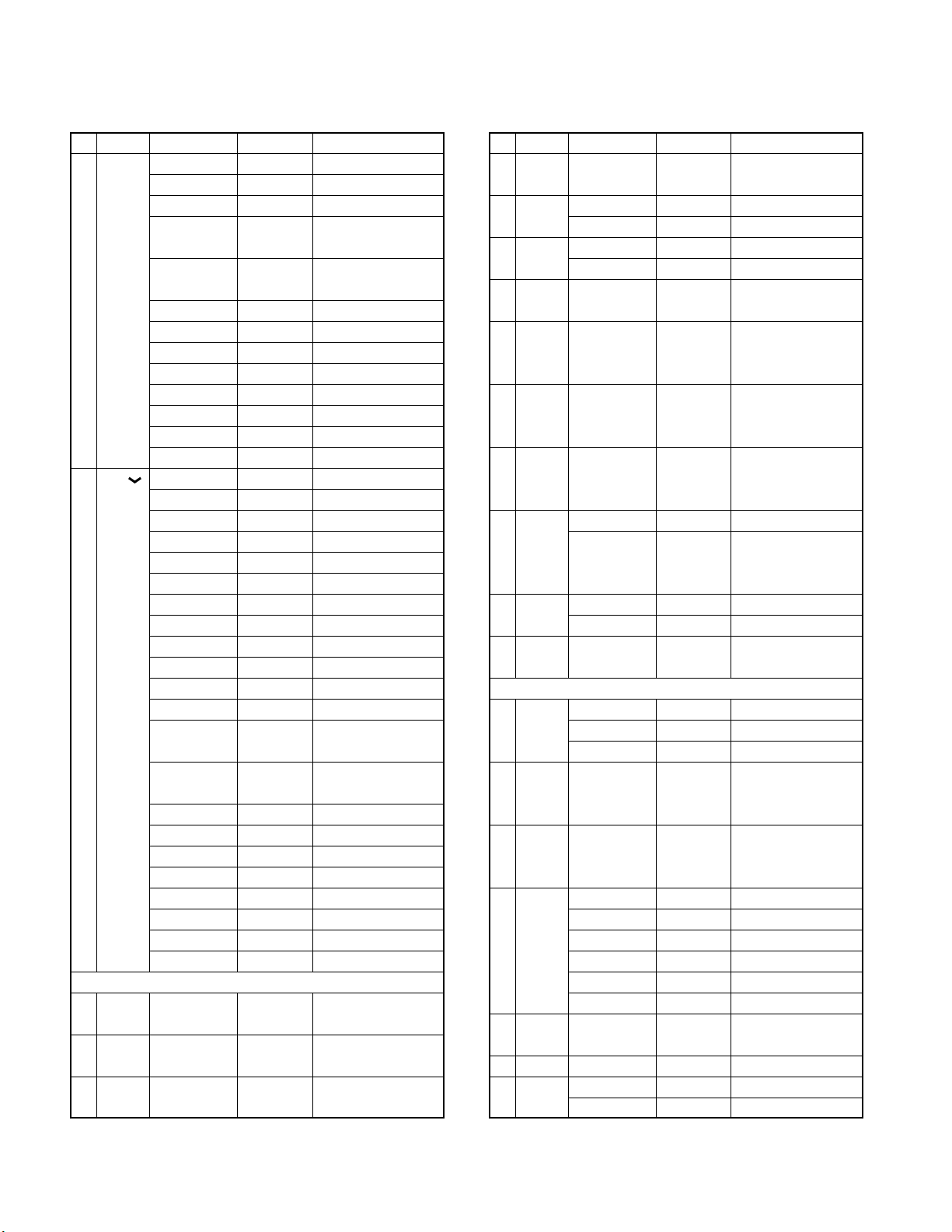
9. Channel Setting Mode
Each channel can be setup in its action mode by using
the panel keys.
• Pressing [MON] when «SELF» is diaplyed, sets channel
setting mode.
• Select an item set using [
with the [CH
/ ].
• The data displayed using [D/A] is stored in the memory
and then proceeds to the next item.
• Pressing [
] proceeds to the next item without storing it
in the memory.
• Press [MON] to set the display to «SELF» and return to
reset (default) status.
The setup items fro channel setting mode are listed be-
low.
No. Function
Select 1~128 __1-__1._ [ ] : Group selection/
channel __1-128._ Channel selection
Select 1~128 __1.-__1_ change
group 128.-__1_
1 RX Step STP__250 Display when an item
frequency
2 RX Off — — — — — — — — [ ] : Off/QT/DQT
signalling
Choices Display Remarks
2.5kHz~1MHz STP_1000 is selected or when a
Blank — — — — — — — — [ ] : Frequency on/
100.0000~ R.100.0000 blank switching
550.0000MHz The rightmost dot
QT 67.0~250.3Hz
(EIA mode) QT_250.3_ [A] : Mode switching
QT 67.0~250.3Hz
(0.1Hz step mode)
DQT 000~777 DQT000N*
(Normal) DQT777N*
(1 step mode)
DQT 023~754 DQT023N_
(Normal) DQT754N_
(Standard table mode)
DQT 000~777 DQT000I*
(Inverse) DQT777I*
(1 step mode)
DQT 023~754 DQT023I_
(Inverse) DQT754I_
(Standard table mode)
] then change the selection
step is changed
(about 0.5 seconds)
[A] : Step change
2.5, 5.0, 6.25, 7.5kHz,
1MHz step
indicates 50Hz digit
(On=5, Off=0)
QT__67.0_ switching
QT__67.0* [SCN] : Normal/
QT_250.3* Inverse switching
13
TK -760G/7 62G
REALIGNMENT
No. Function
3 TX Step STP__250 Display when an item
frequency
4 TX Off — — — — — — — — [ ] : Off/QT/DQT
signalling
5 Option Off NONE____ ←Default
signalling
6 ID 000~ ___ID___ Display when an item
7 Busy No BCL_NO__ ←Default
channel Type 1 BCL_1___ BCL_YES_ for K type
lockout Type 2 BCL_2___ Not used for K type
8 Beat No SHFT_NO_ ←Default
shift Yes SHFT_YES
Choices Display Remarks
2.5kHz~1MHz STP_1000 is selected or when a
step is changed
(about 0.5 seconds)
[A] : Step change
2.5, 5.0, 6.25, 7.5kHz,
1MHz step
Blank — — — — — — — — [ ] : Frequency on/
100.0000~ T.100.0000 blank switching
550.0000MHz The rightmost dot
indicates 50Hz digit
(On=5, Off=0)
QT 67.0~250.3Hz
(EIA mode) QT_250.3_ [A] : Mode switching
QT 67.0~250.3Hz
(0.1Hz step mode)
DQT 000~777 DQT000N*
(Normal) DQT777N*
(1 step mode)
DQT 023~754 DQT023N_
(Normal) DQT754N_
(Standard table mode)
DQT 000~777 DQT000I*
(Inverse) DQT777I*
(1 step mode)
DQT 023~754 DQT023I_
(Inverse) DQT754I_
(Standard table mode)
DTMF DTMF____
2-TONE 2TONE___
9999999999 is selected (about
Blank — — — — — — — — [ ] : Data clear
QT__67.0_ switching
QT__67.0* [SCN] : Normal/
QT_250.3* Inverse switching
0.5 seconds)
12345678 Display of the current
setting (If it is 8 or
more digits, scroll it)
— — — — — 987 Display when a code
is input (Input it with
DTMF key)
No. Function
9 RF High power PWR_H___ ←Default
power Low power PWR_L___
10 Wide/ Wide WIDE____
Narrow Narrow NARROW__
11 Scan DELETE SCAN_DEL Not used for 8ch
Delete/Add
12 Priority No P.CH_NO__ Not used when (Scan)
channel Yes P.CH_YES_ priority is not fixed
13 Home No H.CH_NO__ Not used when home
channel Yes H.CH_YES_ channel is not set in
14
Compander
15 PTT ID OFF P.ID_OFF_
16 Begin 000~ _BOT_ID_ Not valid if Dial ID=
of TX ID
17 End of 000~ _EOT_ID_ Not valid of Dial ID=
TX ID
Choices Display Remarks
ADD SCAN_ADD ←Default
key assignment
No COMP_NO_ Not used when wide
is selected
Yes COMP_YES
Begin of TX P.ID_1___
End of TX P.ID_2___
Both P.ID_3___
9999999999999999
12345678 Display of the current
— — — — — 987 Display when a code
Blank — — — — — — — — [ ] : Data clear
9999999999999999
12345678 Display of the current
— — — — — 987 Display when a code
Blank — — — — — — — — [ ] : Data clear
disable and PTT ID=
off, or EOT is set
Display when an item
is selected (about
0.5 seconds)
setting (If it is 8 or
more digits, scroll it)
is input (Input it with
DTMF key)
Idisable and PTT ID=
off, or BOT is set
Display when an item
is selected (about
0.5 seconds)
setting (If it is 8 or
more digits, scroll it)
is input (Input it with
DTMF key)
14
REALIGNMENT
TK -7 60G /7 62G
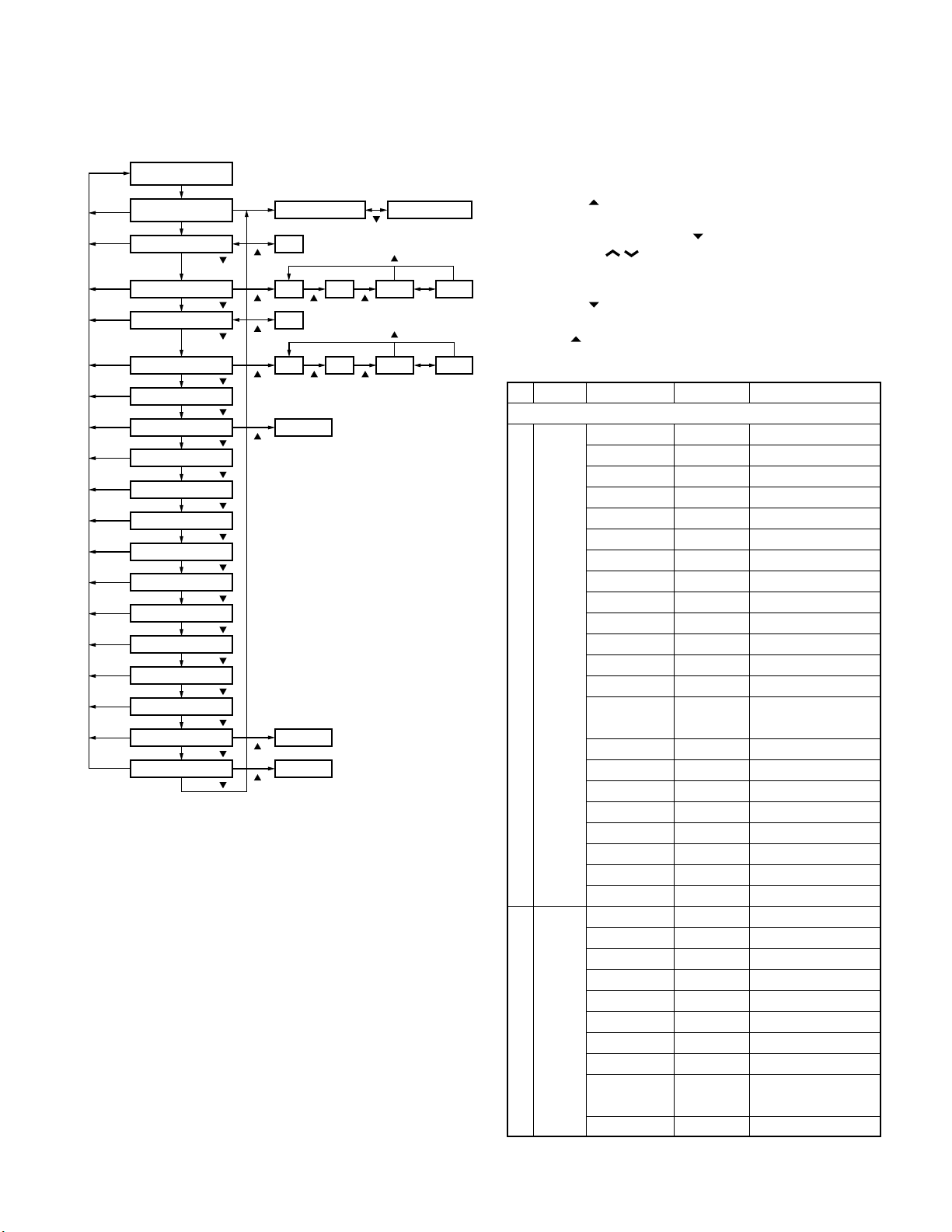
9-1. Flow Chart
Self programming
mode
[MON]
[MON]
[MON]
[MON]
[MON]
[MON]
Option signalling
[MON]
[MON]
Busy channel lockout
[MON]
[MON]
[MON]
[MON]
[MON]
[MON]
[MON]
[MON]
[MON]
[MON]
Beat shift yes/no
RF power high/low
Compander yes/no
[MON]
Channel setting
mode
[D/A]
RX frequency
[D/A]/[ ]
RX signalling
[D/A]/[ ]
TX freuency
[D/A]/[ ]
TX signalling
[D/A]/[ ]
[D/A]/[ ]
ID
[D/A]/[ ]
[D/A]/[ ]
[D/A]/[ ]
[D/A]/[ ]
Wide/Narrow
[D/A]/[ ]
Scan delete/add
[D/A]/[ ]
Priority channel Not used when (Scan) priority is not fixed.
[D/A]/[ ]
Home channel
[D/A]/[ ]
[D/A]/[ ]
PTT ID
[D/A]/[ ]
Begin of TX ID
[D/A]/[ ]
End of TX ID
[D/A]/[ ]
Channel selection Group selection
OFF
[ ]
OFF QT
[ ]
[ ]
[ ]
[ ]
Not used when home channel is not set
in key assignment.
Not used when wide is selected.
[ ]
[ ]
[ ] [ ]
OFF
OFF QT
[ ] [ ]
Data clear
Data clear
Data clear
[ ]
[ ]
DQT N DQT I
[SCN]
[ ]
DQT N DQT I
[SCN]
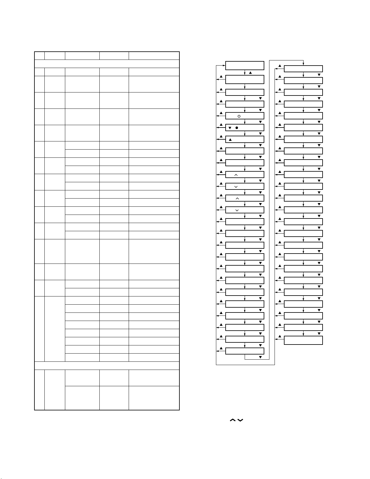
10. Function Setting Mode
All channels can be set up together in the action mode by
using the panel keys.
• Pressing [
setting mode.
• Select an item set using [
with the [CH
• The data displayed using [D/A] is stored in the memory
and then proceeds to the next item.
• Pressing [
in the memory.
• Press [
status.
No. Function
1 [MON] Not function MON__OFF
(
TK-760G
only) Volume up MON___2_
2 [A] No function KEY1_OFF ←Default (TK-760G)
(TK-760G)
[MON] Volume up KEY1__2_
(TK-762G)
] when «SELF» is displayed, sets the function
] then change the selection
/ ].
] proceeds to the next item without storing it
] to display «SELF» and return to reset (default)
Choices Display Remarks
Function key
Volume down MON___1_
Talk around MON___3_
Auxiliary MON___4_
Dispaly character
Home channel MON___7_
Channel down MON___8_
Channel up MON___9_
Key lock MON___10
Public address MON___12
Horn alert MON___14
Selectable QT MON___15 M destination only
2-tone encode MON___16
select
Monitor A MON___17 ←Default
Monitor B MON___18
Monitor C MON___19
Monitor D MON___20
Scan MON___22
Scan del/add MON___23
Group down MON___24
Group up MON___25
Volume down KEY1__1_
Talk around KEY1__3_
Auxiliary KEY1__4_
Dispaly character
Home channel KEY1__7_
Channel down KEY1__8_
Channel up KEY1__9_
Key lock KEY1__10
Public address
MON___5_
KEY1__5_
KEY1__12
TK-762G cannot be selected
15
TK -760G/7 62G
REALIGNMENT
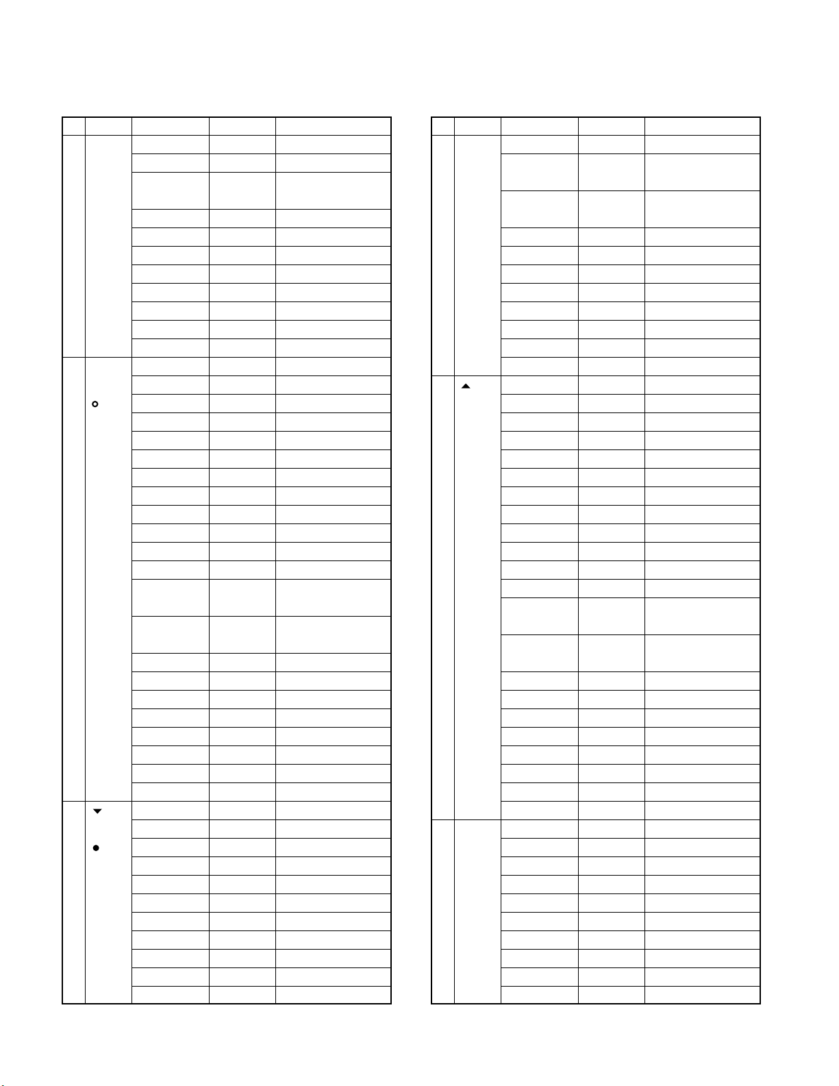
No. Function
3 [D/A] No function KEY2_OFF ←Default
(TK-760G)
[ ] Volume up KEY2__2_
(TK-762G)
4[] No function KEY3_OFF ←Default
(TK-760G)
[ ] Volume up KEY3__2_
(TK-762G)
Choices Display Remarks
Horn alert KEY1__14
Selectable QT
2-tone encode KEY1__16
select
Monitor A KEY1__17 ←Default (TK-762G)
Monitor B KEY1__18
Monitor C KEY1__19
Monitor D KEY1__20
Scan KEY1__22
Scan del/add KEY1__23
Group down KEY1__24
Group up KEY1__25
Volume down KEY2__1_
Talk around KEY2__3_
Auxiliary KEY2__4_
Dispaly character
Home channel
Channel down
Channel up KEY2__9_
Key lock KEY2__10
Public address
Horn alert KEY2__14
Selectable QT KEY2__15 M destination only
2-tone encode KEY2__16
select
Monitor A KEY2__17
Monitor B KEY2__18
Monitor C KEY2__19
Monitor D KEY2__20
Scan KEY2__22
Scan del/add KEY2__23
Group down KEY2__24
Group up KEY2__25
Volume down KEY3__1_
Talk around KEY3__3_
Auxiliary KEY3__4_
Dispaly character
Home channel
Channel down KEY3__8_
Channel up KEY3__9_
Key lock KEY3__10
Public address KEY3__12
KEY1__15 M destination only
TK-762G cannot be selected
TK-762G cannot be selected
TK-762G cannot be selected
TK-762G cannot be selected
KEY2__5_
KEY2__7_
KEY2__8_
KEY2__12
KEY3__5_
KEY3__7_
TK-762G cannot be selected
TK-762G cannot be selected
TK-762G cannot be selected
TK-762G cannot be selected
TK-762G cannot be selected
TK-762G cannot be selected
TK-762G cannot be selected
No. Function
5[] No function KEY4_OFF ←Default
(TK-760G)
[A] Volume up KEY4__2_
(TK-762G)
6 [SCN] No function SCN__OFF ←Default
(TK-760G
only) Volume up SCN___2_
Choices Display Remarks
Horn alert KEY3__14
Selectable QT KEY3__15 M destination only
TK-762G cannot be selected
2-tone encode KEY3__16
select
Monitor A KEY3__17
Monitor B KEY3__18
Monitor C KEY3__19
Monitor D KEY3__20
Scan KEY3__22
Scan del/add KEY3__23
Group down KEY3__24
Group up KEY3__25
Volume down KEY4__1_
Talk around KEY4__3_
Auxiliary KEY4__4_
Dispaly character
Home channel KEY4__7_
Channel down KEY4__8_
Channel up KEY4__9_
Key lock KEY4__10
Public address KEY4__12
Horn alert KEY4__14
Selectable QT KEY4__15 M destination only
2-tone encode KEY4__16
select
Monitor A KEY4__17
Monitor B KEY4__18
Monitor C KEY4__19
Monitor D KEY4__20
Scan KEY4__22
Scan del/add KEY4__23
Group down KEY4__24
Group up KEY4__25
Volume down SCN___1_
Talk around SCN___3_
Auxiliary SCN___4_
Dispaly character
Home channel SCN___7_
Channel down SCN___8_
Channel up SCN___9_
Key lock SCN___10
KEY4__5_
SCN___5_
TK-762G cannot be selected
TK-762G cannot be selected
TK-762G cannot be selected
TK-762G cannot be selected
TK-762G cannot be selected
TK-762G cannot be selected
TK-762G cannot be selected
TK-762G cannot be selected
TK-762G cannot be selected
TK-762G cannot be selected
16
REALIGNMENT
TK -7 60G /7 62G
No. Function
7 [FOOT] No function FSW__OFF ←Default
(FOOT Volume down FSW___1_
SW) Volume up FSW___2_
8 [CH ] No function CUP__OFF
(
Channel
up) Volume up CUP___2_
Choices Display Remarks
Public address SCN___12
Horn alert SCN___14
Selectable QT SCN___15 M destination only
2-tone encode SCN___16
select
Monitor A SCN___17
Monitor B SCN___18
Monitor C SCN___19
Monitor D SCN___20
Scan SCN___22
Scan del/add SCN___23
Group down SCN___24
Group up SCN___25
Talk around FSW___3_
Auxiliary FSW___4_
Dispaly character
Emergency FSW___6_
Home channel FSW___7_
Channel down FSW___8_
Channel up FSW___9_
Key lock FSW___10
Public address FSW___12
Horn alert FSW___14
Selectable QT FSW___15 M destination only
2-tone encode FSW___16
select
Monitor A FSW___17
Monitor B FSW___18
Monitor C FSW___19
Monitor D FSW___20
Scan FSW___22
Scan del/add FSW___23
Group down FSW___24
Group up FSW___25
Volume down CUP___1_
Talk around CUP___3_
Auxiliary CUP___4_
Dispaly character
Home channel
Channel down
Channel up CUP___9_ ←Default
Key lock CUP___10
FSW___5_
CUP___5_
CUP___7_
CUP___8_
TK-762G cannot be selected
No. Function
9 [CH ] No function CDN__OFF
(
Channel
down) Volume up CDN___2_
10 [VOL ] No function VUP__OFF
(
Volume
up) Volume up VUP___2_ ←Default
Choices Display Remarks
Public address
Horn alert CUP___14
Selectable QT CUP___15 M destination only
2-tone encode CUP___16
select
Monitor A CUP___17
Monitor B CUP___18
Monitor C CUP___19
Monitor D CUP___20
Scan CUP___22
Scan del/add CUP___23
Group down CUP___24
Group up CUP___25
Volume down CDN___1_
Talk around CDN___3_
Auxiliary CDN___4_
Dispaly character
Home channel
Channel down
Channel up CDN___9_
Key lock CDN___10
Public address
Horn alert CDN___14
Selectable QT CDN___15 M destination only
2-tone encode CDN___16
select
Monitor A CDN___17
Monitor B CDN___18
Monitor C CDN___19
Monitor D CDN___20
Scan CDN___22
Scan del/add CDN___23
Group down CDN___24
Group up CDN___25
Volume down VUP___1_
Talk around VUP___3_
Auxiliary VUP___4_
Dispaly character
Home channel
Channel down
Channel up VUP___9_
CUP___12
CDN___5_
CDN___7_
CDN___8_ ←Default
CDN___12
VUP___5_
VUP___7_
VUP___8_
TK-762G cannot be selected
TK-762G cannot be selected
TK-762G cannot be selected
TK-762G cannot be selected
TK-762G cannot be selected
TK-762G cannot be selected
TK-762G cannot be selected
TK-762G cannot be selected
TK-762G cannot be selected
TK-762G cannot be selected
TK-762G cannot be selected
TK-762G cannot be selected
17
TK -760G/7 62G
REALIGNMENT
No. Function
11 [VOL ] No function VDN__OFF
(
Volume
down) Volume up VDN___2_
12 Power YES/NO PONT_YES Default : Yes
on tone
13 Control YES/NO CNTT_YES Default : Yes
tone
14 Warning YES/NO WART_YES Default : Yes
tone
Choices Display Remarks
Key lock VUP___10
Public address
Horn alert VUP___14
Selectable QT
2-tone encode VUP___16
select
Monitor A VUP___17
Monitor B VUP___18
Monitor C VUP___19
Monitor D VUP___20
Scan VUP___22
Scan del/add VUP___23
Group down VUP___24
Group up VUP___25
Volume down VDN___1_ ←Default
Talk around VDN___3_
Auxiliary VDN___4_
Dispaly character
Home channel
Channel down
Channel up VDN___9_
Key lock VDN___10
Public address
Horn alert VDN___14
Selectable QT
2-tone encode VDN___16
select
Monitor A VDN___17
Monitor B VDN___18
Monitor C VDN___19
Monitor D VDN___20
Scan VDN___22
Scan del/add VDN___23
Group down VDN___24
Group up VDN___25
VUP___12
VUP___15 M destination only
TK-762G cannot be selected
TK-762G cannot be selected
TK-762G cannot be selected
TK-762G cannot be selected
TK-762G cannot be selected
VDN___5_
VDN___7_
VDN___8_
VDN___12
VDN___15 M destination only
Optional feature
TK-762G cannot be selected
TK-762G cannot be selected
TK-762G cannot be selected
TK-762G cannot be selected
TK-762G cannot be selected
TK-762G cannot be selected
No. Function
15
Minimum
volume
16
Off hook
decode Disable H_D__DIS ←Default
17
Off hook
horn alert
18
Time out
timer 15s step
19 TOT OFF, 1~10/ TOTP_OFF Cannot be set when
pre-alert
time Default : Off
20 TOT OFF, 1~60/ TOTK_OFF Cannot be set when
rekey 1s step TOT is off
time Default : Off
21 TOT OFF, 1~15/ TOTS_OFF Cannot be set when
reset 1s step TOT is off
time
22 Clear to YES CTT_YES_
transpond
(BCL for
transpond)
23
Signalling
24 Squelch 0~9/1 step SQL__5__ Default : 5
level
25 Priority None PRI_NONE Default : None
26 Look 0.5~5.0/ LBA__500 Default : 500ms
back 0.05s Cannot be set when
time A Priority=none
27 Look 0.5~5.0/ LBB_2000 Default : 2000ms
back 0.05s Cannot be set when
time B Priority=none
28 Revert Selected REV_SEL_
channel Last called REV_L/C_ ←Default
29 Dropout 0~300/1s DODT___3 Default : 3s
delay time
30
Dwell time
31
Off hook
scan Disable H_S__DIS ←Default
Choices Display Remarks
0~31/1 step MVOL_12_
Enable H_D__ENA
Enable H_H__ENA
Disable H_H__DIS ←Default
OFF, 15~600/ TOT_180_ Default : 180s
1s step TOT is off
NO CTT_NO__ ←Default
OR SIG__OR_ ←Default
AND SIG__AND
Scan
Fixed PRI_FIX_
Selected PRI_SEL_
Last used REV_L/U_
Selected+Talk back
Priority REV_PRI_
Priority+Talk back
0~300/1s DWL____3 Default : 3s
Enable H_S__ENA
REV_S/T_
REV_P/T_
18
REALIGNMENT
Self programming
mode
Function setting
mode
[MON] key function
[D/A]/[ ]
[A]/[MON] key function
[D/A]/[ ] key function
[ ]/[ ] key function
[ ]/[A] key function
[SCN] key function
[FOOT] key function
[D/A]/[ ]
[D/A]/[ ]
[D/A]/[ ]
[D/A]/[ ]
[D/A]/[ ]
[CH ] key function
[D/A]/[ ]
[CH ] key function
[D/A]/[ ]
[VOL ] key function
[D/A]/[ ]
[VOL ] key function
[D/A]/[ ]
Power on tone yes/no
[D/A]/[ ]
Control tone yes/no
[D/A]/[ ]
Warning tone yes/no
[D/A]/[ ]
Minimum volume
[D/A]/[ ]
Off hook decode
[D/A]/[ ]
Off hook horn alert
[D/A]/[ ]
[D/A]/[ ]
Time out timer
TOT pre-alert time
[D/A]/[ ]
TOT rekey time
[D/A]/[ ]
TOT reset time
[D/A]/[ ]
Clear to transpond
[D/A]/[ ]
Signalling
[D/A]/[ ]
[D/A]/[ ]
[ ]
[ ]
[ ]
[ ]
[ ]
[ ]
[ ]
[ ]
[ ]
[ ]
[ ]
[ ]
[ ]
[ ]
[ ]
[ ]
[ ]
[ ]
[ ]
[ ]
[ ]
[ ]
[ ]
[ ]
[ ]
Look back time A
Priority
Squelch level
[D/A]/[ ]
Look back time B
Revert channel
Dropout delay time
Dwell time
Off hook scan
Digit time
[D/A]/[ ]
[D/A]/[ ]
[D/A]/[ ]
[D/A]/[ ]
[D/A]/[ ]
[D/A]/[ ]
[D/A]/[ ]
Inter digit time
[D/A]/[ ]
First digit time
[D/A]/[ ]
First digit delay
[D/A]/[ ]
Rise time with QT
[D/A]/[ ]
Dial ID
[D/A]/[ ]
No. of DTMF key
[D/A]/[ ]
DTMF hold time
[D/A]/[ ]
Store & Send
[D/A]/[ ]
D key assignment
[D/A]/[ ]
DTMF signalling
[D/A]/[ ]
[D/A]/[ ]
Inter mediate code
Group code
[D/A]/[ ]
Auto reset time
[D/A]/[ ]
Call alert/Transpond
[D/A]/[ ]
Panel test/
Panel tuning mode
[D/A]/[ ]
[ ]
[ ]
[ ]
[ ]
[ ]
[ ]
[ ]
[ ]
[ ]
[ ]
[ ]
[ ]
[ ]
[ ]
[ ]
[ ]
[ ]
[ ]
[ ]
[ ]
[ ]
[ ]
[ ]
[ ]
TK -7 60G /7 62G
No. Function
Choices Display Remarks
DTMF
32
33
Digit time
Inter digit
50~200ms/10ms
50~1000ms/50ms
DIGT__50 Default : 50ms
IDT___50 Default : 50ms
time
34
First digit
50~200ms/10ms
FDT___50 Default : 50ms
time
35
First digit
50~1000ms/50ms
RIST_100 Default : 100ms
delay
36
Rise time
50~1000ms/50ms
RTWQ_100 Default : 100ms
with QT
37 Dial ID Enable DID__ENA
Disable DID__DIS ←Default
38 No. of 12 key NODK_12_ ←Default
DTMF key
39 DTMF ON DHT__ON_ ←Default
hold time
40
Store and
send Disable SAS__DIS ←Default
41 D key D code DKA_D_CD ←Default
assignment
42 DTMF Code SQ DTMS_CSQ ←Default
signalling
43 Inter 0~9, A~D, IMC__#__ Default : # (Can be
mediate *, # set only when DTMF
code signalling=SEL CALL)
44 Group A~D, *, # GPCD_OFF Default : OFF
code
45 Auto OFF ART__OFF
reset time
46
Call alert
/transpond
47 Panel Enable PTM__ENA ←Default
test/ Not used for TK-762G
panel Disable PTM__DIS
tuning
mode
16 key NODK_16_
OFF DHT__OFF
Enable SAS__ENA
1~16s/1s DKA_16__
SWL CALL DTMF_SEL TK-760G only
1~15s/1s ART__10_ Default : 10s
OFF CA/T_OFF ←Default
Call alert CA/T_C/A
Transpond CA/T_T/A
(Call alert)
Transpond CA/T_T/I
(ID code)
Transpond CA/T_T/T
(Transpond code)
Others
10-1. Flow Chart
11. Memory Reset Mode (TK-760G only)
You can clear all settings you made in self programming
mode, or you can return to the original display.
• Press [SCN] while «SELF» is displayed will change the display to «CANCEL».
• Press [CH
CEL» and «READY».
• When «READY» is displayed, pressing [SCN] will set all
data to default, and «CLEAR» will appear on the display.
Press [SCN] again to display «SELF».
• When «CANCEL» is displayed, pressing [SCN] will cancel
the reset, and «SELF» will be displayed.
/ ] to change the display between «CAN-
19
TK -760G/7 62G
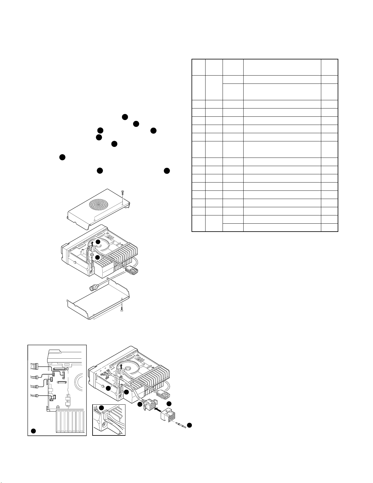
INSTALLATION
1. Accessory Connection Cable
(KCT-19 : Option)
The KCT-19 is an accessory connection cable for con-
necting external equipment. The connector has 15 pins and
the necessary signal lines are selected for use.
1-1. Installing the KCT-19 in the transceiver
1. Remove the upper and lower halves of the transceiver
case, and lift the DC cord bushing ( ) from the chassis.
2. Remove the pad as shown in Figure 1 ( ).
3. Insert the KCT-19 cable ( ) into the chassis ( ).
The wire harness band ( ) must be inside the chassis.
3
5
4. Replace the DC cord bushing ( ).
5. Connect the KCT-19 to the TX-RX unit (A/2) as shown in
Figure 2 ( ).
7
6. Connect the KCT-19 to the external accessory by inserting the crimp terminal ( ) into the square plug ( ),
8 9
both of which are supplied with the KCT-19.
1
2
4
6
1-2. KCT-19 Accessory Port Function
No. No. Name Function
(A)
(B,C,D,E)
1 D-2 RXD Serial control data input *1
DTC Data channel control/ *2
External hook input
2 D-5 ME External microphone ground
3 D-3 IGN Ignition sense input
4 D-1 DEO Receiver detector output
5 D-6 MI External microphone input
6 B-2 E Ground
7 B-3 SB Switched B+, DC 13.6V output.
Maximum 1A
8 D-7 PTT External PTT input *2
9 D-4 DI Data modulation input
10 B-1 HOR Horn alert/call output
11 D-8 SQ Squelch detect output Busy : H *2
12 C-1 SP Speaker audio output.
13 E-1 AM
14 E-2 MM MIC mute input, active high
15 E-3 EMG Foot switch input, active low *3
TXS
Speaker mute input, active high
Transmitter sense output, active high
Note
1
2
*1 : SmarTrunk OMNI mode
*2 : MDT mode
*3 : Emergency mode
Fig. 1
D
CN5
E
B
C
7
CN8
CN3
CN4
E
C
B
B
D
5
4
9
6
3
Crimp terminal
(E23-0613-05)
A
13
15
Square plug
(E09-1571-05)
1
3
Contact
12
8
20
Fig. 2
 Loading…
-
Страница 1
Docum ent Cop yrig hts Cop yrigh t 2006 by K e nw ood Corpo ra tio n. A ll rig hts r es erved . No part of th is ma nu al ma y be rep roduced, tr ansla ted, d istribu ted, o r trans mitted i n any fo rm or b y an y mea ns, electr onic, mech anical, p hotocop ying, r ec ord ing , or othe r wise , for an y purpose w ithout t he prio r written pe rmis[…]
-
Страница 2
© 2000-1 PRINTED IN JAPAN B51-8497-10 ( N ) 1269 VHF FM TRANSCEIVER TK — 7 60G/ 7 62G SER VICE MANUAL REVISED Please use this manual in place of the service manual (preliminary version), B51-8497-00. We have added the information on the circuit description, specifications, and K2 version specifications to the service manual (preliminary version), […]
-
Страница 3
2 T K — 7 60G/ 7 62G CONTENTS / GENERAL GENERAL INTRODUCTION SCOPE OF THIS MANUAL This manual is intended for use by experienced techni- cians familiar with similar types of commercial grade com- munications equipment. It contains all required service in- formation for the equipment and is current as of the publica- tion date. Changes which may occ[…]
-
Страница 4
3 T K — 7 60G / 7 62G 1 3 + – 7 6 13 15 5. INSTALLATION PLANNING – CONTROL STATIONS 5-1. Antenna system Control station. The antenna system selection depends on many factors and is beyond the scope of this manual. Your KENWOOD dealer can help you select an antenna sys- tem that will best serve your particular needs. 5-2. Radio location Select a[…]
-
Страница 5
4 T K — 7 60G/ 7 62G SYSTEM SET -UP Merchandise received License and frequency allocated by FCC Choose the type of transceiver Are you using the public address? Are you using the external speaker? Are you using ignition sense cable? Delivery Are you using the KGP-1A Modem GPS receiver or the KGP-1B Modem GPS controller? T ransceiver programming (Op[…]
-
Страница 6
5 T K — 7 60G / 7 62G 1. Controls and Functions 1-1. TK-760G Front Panel IO (Power) switch Press to switch the transceiver ON (or OFF). LED indicator Lights red while transmitting. Lights green while receiv- ing. Flashes orange while receiving a Code Squelch or Selective Call code, or a 2-Tone code that matches the one set up in your transceiver. /[…]
-
Страница 7
6 T K- 7 60G / 7 62G 1-5. Rear panel Antenna connector External speaker jack Power input connector 1-6. Programmable Auxiliary Functions The following keys can be programmed with the func- tions listed below. TK-760G : / (left side), / (right side), MON, A, D/A, , , and SCN. TK-762G : / (left side), / (right side), MON, , , and A. • AUX • Chann[…]
-
Страница 8
7 T K — 7 60G / 7 62G • Display character (TK-760G only) This key switches the LCD display between the group and channel number and the group and channel name. • Emergency (M market models only) Pressing this key for longer than 1 second causes the transceiver to enter the emergency mode. The transceiver jumps to the programmed «Emergency […]
-
Страница 9
8 T K — 7 60G/ 7 62G ■ SCAN start condition One or more non-priority channels must be added to all channels that can be scanned. The transceiver must be in normal receive mode (PTT off). When you activate the key programmed to the scan func- tion, the scan starts. The scan icon «SCN» lights and «SCAN» is indicated on alphanume[…]
-
Страница 10
9 T K — 7 60G / 7 62G ■ Off hook decode If the Off hook decode function has been enabled, re- moving and replacing the microphone on the hook has no effect for decoding QT/DQT and option signalling. ■ «TOT» pre-alert The transceiver has «TOT pre-alert timer. This parameter selects the time at which the transceiver generates «[…]
-
Страница 11
10 T K — 7 60G/ 7 62G ■ Busy tone Sounds in conventional mode, when busy channel lock- out is functioning. You can select yes or no for the optional feature’s warning tone. ■ Group call tone Sounds when a group call with the correct DTMF/2-tone option signalling is received, repeats 7 times. You can se- lect yes or no for the optional feat[…]
-
Страница 12
11 T K — 7 60G / 7 62G REALIGNMENT 5-4. Programming Software Description The KPG-56D programming disk is supplied in 3-1/2″ disk format. The software on this disk allows a user to program TK-760G/762G radio via a programming interface cable (KPG-46). 5-5. Programming With IBM PC If data is transferred to the transceiver from an IBM PC with the[…]
-
Страница 13
12 T K — 7 60G/ 7 62G Note : You can clone the programmed data between the trans- ceiver listed below. Frequency version must be same. Slave TK-260G TK-260G TK-760G TK-760G TK-760G TK-260G TK-270G KMKM K 2 K 2 M 2 TK-270G TK-270G TK-762G TK-762G TK-762G TK-270G Master K M K M K2 K2 TK-760G YES NO YES NO NO NO NO K TK-760G NO YES NO YES NO NO NO M T[…]
-
Страница 14
13 T K — 7 60G / 7 62G 9. Channel Setting Mode Each channel can be setup in its action mode by using the panel keys. • Pressing [MON] when «SELF» is diaplyed, sets channel setting mode. • Select an item set using [ ] then change the selection with the [CH / ]. • The data displayed using [D/A] is stored in the memory and then proceed[…]
-
Страница 15
14 T K — 7 60G/ 7 62G REALIGNMENT No. Function Choices Display Remarks 9 RF High power PWR_H___ ← Default power Low power PWR_L___ 10 Wide/ Wide WIDE____ Narrow Narrow NARROW__ 11 Scan DELETE SCAN_DEL Not used for 8ch Delete/Add ADD SCAN_ADD ← Default 12 Priority No P.CH_NO__ Not used when (Scan) channel Yes P.CH_YES_ priority is not fixed 13 H[…]
-
Страница 16
15 T K — 7 60G / 7 62G 10. Function Setting Mode All channels can be set up together in the action mode by using the panel keys. • Pressing [ ] when «SELF» is displayed, sets the function setting mode. • Select an item set using [ ] then change the selection with the [CH / ]. • The data displayed using [D/A] is stored in the memory […]
-
Страница 17
16 T K — 7 60G/ 7 62G No. Function Choices Display Remarks Horn alert KEY3__14 Selectable QT KEY3__15 M destination only TK-762G cannot be selected 2-tone encode KEY3__16 select Monitor A KEY3__17 Monitor B KEY3__18 Monitor C KEY3__19 Monitor D KEY3__20 Scan KEY3__22 TK-762G cannot be selected Scan del/add KEY3__23 TK-762G cannot be selected Group […]
-
Страница 18
17 T K — 7 60G / 7 62G No. Function Choices Display Remarks Public address CUP___12 Horn alert CUP___14 Selectable QT CUP___15 M destination only TK-762G cannot be selected 2-tone encode CUP___16 select Monitor A CUP___17 Monitor B CUP___18 Monitor C CUP___19 Monitor D CUP___20 Scan CUP___22 TK-762G cannot be selected Scan del/add CUP___23 TK-762G […]
-
Страница 19
18 T K — 7 60G/ 7 62G No. Function Choices Display Remarks 15 Minimum 0~31/1 step MVOL_12_ volume 16 Off hook Enable H_D__ENA decode Disable H_D__DIS ← Default 17 Off hook Enable H_H__ENA horn alert Disable H_H__DIS ← Default 18 Time out OFF, 15~600/ TOT_180_ Default : 180s timer 15s step 19 TOT OFF, 1~10/ TOTP_OFF Cannot be set when pre-alert […]
-
Страница 20
19 T K — 7 60G / 7 62G REALIGNMENT Self programming mode Function setting mode [MON] key function [D/A]/[ ] [A]/[MON] key function [D/A]/[ ] key function [ ]/[ ] key function [ ]/[A] key function [SCN] key function [FOOT] key function [D/A]/[ ] [D/A]/[ ] [D/A]/[ ] [D/A]/[ ] [D/A]/[ ] [CH ] key function [D/A]/[ ] [CH ] key function [D/A]/[ ] [VOL ] […]
-
Страница 21
20 T K — 7 60G/ 7 62G 3 4 5 6 7 8 9 1. Accessory Connection Cable (KCT-19 : Option) The KCT-19 is an accessory connection cable for con- necting external equipment. The connector has 15 pins and the necessary signal lines are selected for use. 1-1. Installing the KCT-19 in the transceiver 1. Remove the upper and lower halves of the transceiver case[…]
-
Страница 22
21 T K — 7 60G / 7 62G INST ALLA TION 2. Accessory Terminal (TX-RX Unit) 2-1. External Connector Accessory Terminal Method No. Name I/O Description Note CN1 1 8C O DC 8V output 2 5S O DC 5V output 3 AUX5 O SMRD : Reset output *1 4 AUX6 O 5SC : 5S control (Cannot use) *1 5 NC – Non-connection 6 AUX3 O SQ : Squelch detect output *2 7 AUX1 I PTT : E[…]
-
Страница 23
22 T K — 7 60G/ 7 62G INST ALLA TION 3-2. Modifying the Transceiver Modify the transceiver as follows to turn the power or the Horn Alert or Manual Relay function on and off with the ignition key. 1. Remove the lower half of the transceiver case. 2. Set jumper resistors (0 Ω ) R134 and R135 of the TX-RX unit (A/2) as shown in Table 1. TX-RX UNIT […]
-
Страница 24
23 T K — 7 60G / 7 62G INST ALLA TION 1 2 3 4 5 6 2. Fold the flat cable ( ) in the opposite direction ( ). 3. Rotate the control section ( ) 180 degrees ( ). 4. Insert the flat cable into the control section connector, CN501 ( ). 5. Mount the control section on the transceiver ( ). CN501 1 2 3 4 5 6 Fig. 7 6. External Speaker 6-1. KES-3 : Option T[…]
-
Страница 25
24 T K — 7 60G/ 7 62G Frequency Configuration The receiver utilizes double conversion. The first IF is 49.95MHz and the second IF is 450kHz. The first local oscil- lator signal is supplied from the PLL circuit. The PLL circuit in the transmitter generates the neces- sary frequencies. Figure 1 shows the frequencies. Fig. 1 Frequency configuration Re[…]
-
Страница 26
25 T K — 7 60G / 7 62G ■ Wide/Narrow Changeover Circuit The W/N port (pin 4) of the shift register (IC510) is used to switch between ceramic filters. When the W/N port is high, Q4 turns on and the ceramic filter SW diode (D8, D10) CF1 turns on to receive a Narrow signal. At the same time, Q35 turns on and one of the filters is selected so that th[…]
-
Страница 27
26 T K — 7 60G/ 7 62G D102,104 Q103 TX VCO Q106 BUFF AMP D101,103 Q101 RX VCO Q102, 104,105 T/R SW Charge pump LPF Phase comparator 1/M 1/N PLL/VCO 5kHz/6.25kHz 5kHz/6.25kHz REF OSC 16.8MHz PLL D ATA IC3 : PLL IC Q9 RF AMP Fig. 6 PLL circuit ■ Unlock Circuit During reception, the 8RC signal goes high, the 8TC sig- nal goes low, and Q16 turns on. […]
-
Страница 28
27 T K — 7 60G / 7 62G ■ APC Circuit The automatic transmission power control (APC) circuit detects part of a power module output with a diode (D35, D36) and applies a voltage to IC15. IC15 compares the APC control voltage (PC) generated by the D/A converter (IC6) and DC amplifier (IC7) with the detection output voltage to control Q31 and Q32, ge[…]
-
Страница 29
28 T K — 7 60G/ 7 62G ■ Encode The QT and DQT signals are output from TO of the CPU (IC502) and summed with the external pin DI line by the summing amplifier (IC2) and the resulting signal goes to the D/A converter (IC6) of the TX-RX unit. The DTMF and 2- TONE signals are output from DTMF of the CPU and goes to the audio processor (IC508). The si[…]
-
Страница 30
29 T K — 7 60G / 7 62G SEMICONDUCTOR DA T A ■ Terminal function Pin No. Name I/O Function 1 EMGT O External MIC control. Mobile MIC : H 2 DTMF O DTMF/2TONE/BEEP output. 3 2TN I 2TONE decode pulse input. 4 DTMSTD I DTMF decode detect. Detect : H 5 SIM I Destination select. 6 BYTE I +5V (5C). 7 CNVSS I GND. 8 AFSTB O Base band IC strobe/reset outpu[…]
-
Страница 31
30 T K — 7 60G/ 7 62G SEMICONDUCTOR DA T A Shift Register : BU4094BCFV ■ Terminal function (TX-RX unit IC510) Pin No. Port Name Function 4 Q1 W/N Wide/Narrow SW. Narrow : H 5 Q2 MUTE MIC mute (M models only). Mute : H 6 Q3 MBL MIC/LCD backlight control. Backlight on : H 7 Q4 LED0 Red LED. LED lights : H 11 Q8 BSHIFT Beat shift. Shift on : H 12 Q7[…]
-
Страница 32
31 T K — 7 60G / 7 62G DESCRIPTION OF COMPONENTS Display Unit (X54-3270-10) : TK-760G Ref. No. Use/Function Operation/Condition D801 Reverse current prevention D802~805 Light emission D808 Current stability IC801 LCD driver Q801 DC switch (LED) Display Unit (X54-3280-10) : TK-762G Ref. No. Use/Function Operation/Condition D801 Light emission D802 R[…]
-
Страница 33
32 T K — 7 60G/ 7 62G DESCRIPTION OF COMPONENTS Ref. No. Use/Function Operation/Condition IC9 Shift/Store register HNC, 8RC, 8TC, SPMUTE, RX, PA/LI, AUX5, AUX6 IC10 5V AVR 5C (TX/RX) IC11 9V AVR 9C IC12 8V AVR 8C IC13 AF amplifier IC14 Power supply logic circuit control IC15 DC amplifier APC control IC400 Power module IC501 Flash ROM IC502 CPU IC50[…]
-
Страница 34
33 T K — 7 60G/ 7 62G 2nd Word G H J K L ppm/ ° C ± 30 ± 60 ± 120 ± 250 ± 500 Example : CC45TH = –470 ± 60ppm/ ° C Multiplier 2nd number 1st number 2 2 0 = 22pF CAPACITORS CC 45 TH 1H 220 J 12 3 4 5 6 1 = Type … ceramic, electrolytic, etc. 4 = Voltage rating 2 = Shape … round, square, ect. 5 = Value 3 = Temp. coefficient 6 = Tolerance[…]
-
Страница 35
TK — 7 60G/ 7 62G PA R T S L I S T 34 * New Parts. indicates safety critical components. Parts without Parts No. are not supplied. Les articles non mentionnes dans le Parts No. ne sont pas fournis. Teile ohne Parts No. werden nicht geliefert. L : Scandinavia K : USA P : Canada Y : PX (Far East, Hawaii) T : England E : Europe Y : AAFES (Europe) X : […]
-
Страница 36
TK — 7 60G/ 7 62G P ARTS LIST 35 Ref. No. Address Parts No. Description Ref. No. Address Parts No. Description New Desti- parts nation New Desti- parts nation D509-514 B30-2050-05 LED D521 B30-2151-05 LED (RED/GRN) C1-19 CK73GB1H102K CHIP C 1000PF K C20 C92-0507-05 CHIP-TAN 4.7UF 6.3WV C21 CK73GB1H102K CHIP C 1000PF K C22 CK73GB1C104K CHIP C 0.10UF[…]
-
Страница 37
TK — 7 60G/ 7 62G PA R T S L I S T 36 Ref. No. Address Parts No. Description Ref. No. Address Parts No. Description New Desti- parts nation New Desti- parts nation C172 CE04EW1E471M ELECTRO 470UF 25WV C173 CK73GB1C104K CHIP C 0.10UF K C174 CK73GB1H102K CHIP C 1000PF K C175 CC73GCH1H080D CHIP C 8.0PF D K,M C175 CC73GCH1H100D CHIP C 10PF D K2 C177 CK[…]
-
Страница 38
TK — 7 60G/ 7 62G P ARTS LIST 37 Ref. No. Address Parts No. Description Ref. No. Address Parts No. Description New Desti- parts nation New Desti- parts nation C582 CK73GB1C473K CHIP C 0.047UF K C583 C92-0566-05 CHIP-TAN 10UF 6.3WV C584 CK73GB1H103K CHIP C 0.010UF K C585 CC73GCH1H101J CHIP C 100PF J C587 CK73GB1H103K CHIP C 0.010UF K C589 C92-0606-0[…]
-
Страница 39
TK — 7 60G/ 7 62G PA R T S L I S T 38 Ref. No. Address Parts No. Description Ref. No. Address Parts No. Description New Desti- parts nation New Desti- parts nation R36 RK73GB1J223J CHIP R 22K J 1/16W R37 RK73GB1J220J CHIP R 22 J 1/16W R38-40 RK73GB1J103J CHIP R 10K J 1/16W R41 RK73GB1J224J CHIP R 220K J 1/16W R42 RK73GB1J473J CHIP R 47K J 1/16W R43[…]
-
Страница 40
TK — 7 60G/ 7 62G P ARTS LIST 39 Ref. No. Address Parts No. Description Ref. No. Address Parts No. Description New Desti- parts nation New Desti- parts nation R175 RK73GB1J682J CHIP R 6.8K J 1/16W R176 RK73GB1J104J CHIP R 100K J 1/16W R177 R92-1261-05 CHIP R 150 J 1/2W R178 RK73GB1J103J CHIP R 10K J 1/16W R179-181 RK73GB1J223J CHIP R 22K J 1/16W R1[…]
-
Страница 41
TK — 7 60G/ 7 62G PA R T S L I S T 40 Ref. No. Address Parts No. Description Ref. No. Address Parts No. Description New Desti- parts nation New Desti- parts nation R619 RK73GB1J104J CHIP R 100K J 1/16W R620,621 RK73GB1J103J CHIP R 10K J 1/16W R622 RK73GB1J473J CHIP R 47K J 1/16W R701 RD14BB2C473J RD 47K J 1/6W R704 RK73GB1J223J CHIP R 22K J 1/16W D[…]
-
Страница 42
TK — 7 60G/ 7 62G P ARTS LIST 41 Ref. No. Address Parts No. Description Ref. No. Address Parts No. Description New Desti- parts nation New Desti- parts nation PLL/VCO (X58-4670-XX) C107 CC73GCH1H080D CHIP C 8.0PF D K,M C110 CC73GCH1H040B CHIP C 4.0PF B K,M C110 CC73GCH1H120J CHIP C 12PF J K2 C111 CC73GCH1H040B CHIP C 4.0PF B K2 C111 CC73GCH1H050B C[…]
-
Страница 43
42 T K — 7 60G / 7 62G EXPLODED VIEW (TK-760G) Parts with the exploded numbers larger than 700 are not supplied. 1 2 A B C 1 24 3 24 2 40 37 7 11 6 17 22 22 23×2 27 24 9 25 14 12 21×2 44 26 IC400 16 701 702 Cx2 703 A C C Cx2 Dx11 B B A Ax2 703 TX-RX unit (X57-595) (B/2) TX-RX unit (X57-595) (A/2) Display unit (X54-327) 704 A M2.6 x 6 (OC) BLK : N33[…]
-
Страница 44
43 T K — 7 60G/ 7 62G EXPLODED VIEW (TK-762G) 1 2 D E F 1 24 3 24 2 40 37 11 6 7 28 17 22 22 23×2 27 24 9 25 14 12 21×2 44 26 IC400 16 701 702 Cx2 703 C C Cx2 Dx11 B B A A Ax2 703 TX-RX unit (X57-595) (B/2) TX-RX unit (X57-595) (A/2) Display unit (X54-328) 704 A M2.6 x 6 (OC) BLK : N33-2606-45 B M3 x 8 : N67-3008-46 C M2.6 x 6 (Br-T ap) : N87-2606-[…]
-
Страница 45
44 T K — 7 60G / 7 62G P ACKING Parts with the exploded numbers larger than 700 are not supplied. G H 1 2 3 5 Cap (B09-0235-05) 8 Instruction manual (B62-1257-10) : M (B62-1258-00) : K,K2 705 W arranty card 13 DC cord (E30-3339-05) 19 Fuse (10A) (F51-0016-05) x 2 30 Polystyrene foamed fixture (F) (H10-6618-12) 31 Polystyrene foamed fixture (R) (H10[…]
-
Страница 46
45 T K — 7 60G/ 7 62G ADJUSTMENT Test Mode (TK-760G Only) ■ Test Mode Operating Features This transceiver has a test mode. To enter test mode, press [SCN] key and turn power on. Hold [SCN] key un- til test channel No. and test signalling No. appears on LCD. Test mode can be inhibited by programming. To exit test mode, switch the power on again. T[…]
-
Страница 47
46 T K — 7 60G / 7 62G FREQ_ _XX Frequency adj. Display Function name HPOW_XXX RF high power H.POW_XXX Hi power (L) H.P .OW_XXX Hi power (L’) [A] [D/A] [D/A] [D/A] [D/A] [D/A] H.P .O.W_XXX Hi power (C) H.P .O.W._XXX Hi power (H’) H.P .O.W._.XXX Hi power (H) LPOW_XXX RF low power L.POW_XXX Low power (L) L.P .OW_XXX Low power (L’) [A] […]
-
Страница 48
47 T K — 7 60G/ 7 62G Test Equipment Required for Alignment Test Equipment Major Specifications 1. Standard Signal Generator Frequency Range 136 to 174MHz (SSG) Modulation Frequency modulation and external modulation Output –127dBm/0.1 µ V to greater than –7dBm/100mV 2. Power Meter Input Impedance 50 Ω Operation Frequency 136 to 174MHz or mo[…]
-
Страница 49
48 T K — 7 60G / 7 62G ADJUSTMENT Adjustment Location ■ Switch (TK-760G) ■ Adjustment Point ■ Note • Flash memory The firmware program (User mode, Test mode, Tuning mode, etc.) and the data programmed by the FPU (KPG-56D) for the flash memory, is stored in memory. When parts are changed, program the data again. • EEPROM The tuning data (D[…]
-
Страница 50
49 ADJUSTMENT Measurement Test- equipment Unit Terminal Adjustment Unit Parts Method Specifications/Remarks Condition Item T K — 7 60G/ 7 62G Receiver Section 1. Discriminator 1) Set test mode SSG Rear ANT TX-RX L5 AF output maximum. • Wide CH : CH1 — Sig1 panel (A/2) SSG output : –53dBm/501 µ V AF VTVM ACC SSG MOD : 3kHz Oscilloscope (EXT.SP)[…]
-
Страница 51
ADJUSTMENT Measurement Test- equipment Unit Terminal Adjustment Unit Parts Method Specifications/Remarks Condition Item 50 T K — 7 60G / 7 62G 3. Squelch 3 1) Set test mode SSG Rear ANT Front CH / Adjust to the • Wide Select “SQL3” in tuning mode. panel panel squelch threshold “S . QL3” AF VTVM ACC point. Adjust [ *** ] Distortion (EXT.SP[…]
-
Страница 52
51 ADJUSTMENT Measurement Test- equipment Unit Terminal Adjustment Unit Parts Method Specifications/Remarks Condition Item T K — 7 60G/ 7 62G 6. QT check 1) Set test mode SSG Rear ANT CH : CH1 — Sig4 panel SSG MOD AF VTVM ACC INT : 3kHz (Wide), 1.5kHz (Narrow) Distortion (EXT.SP) EXT : 151.4Hz meter SSG system MOD DEV Oscilloscope : ± 3.75kHz (Wid[…]
-
Страница 53
ADJUSTMENT Measurement Test- equipment Unit Terminal Adjustment Unit Parts Method Specifications/Remarks Condition Item 52 T K — 7 60G / 7 62G 3) “L . P . O . W” Power meter Rear ANT Front CH / 5.0W ± 0.5W PTT : ON panel panel Adjust [ *** ] 4) “L . P . O . W . ” PTT : ON Adjust [ *** ] 5) “L . P . O . W . _ . ” PTT : ON Adjust [ *** ][…]
-
Страница 54
53 ADJUSTMENT Measurement Test- equipment Unit Terminal Adjustment Unit Parts Method Specifications/Remarks Condition Item T K — 7 60G/ 7 62G 8. MIC 1) Set test mode Power meter Rear ANT Check ± 3kHz ± 0.2kHz (Wide) seisitivity CH : CH1 — Sig1 Deviation panel ± 1.5kHz ± 0.05kHz (Narrow) check AG : 1kHz/5mV meter PTT : ON Oscilloscope Adjust [ *[…]
-
Страница 55
54 T K — 7 60G / 7 62G AC E BD 1 3 5 7 2 4 6 T K — 7 60G / 7 62G PC BOARD VIEWS DISPLAY UNIT (X54-3270-10) : TK-760G Component side view DISPLAY UNIT (X54-3270-10) : TK-760G Foil side view D804 D803 D805 D802 J72-0683-02 CN801 MBL 5C CE CL E E SB DI 1 2 7 8 C801 C802 C803 C804 C805 C806 C807 D801 D808 IC801 B C E Q801 R801 R802 R803 R804 R805 R806 […]
-
Страница 56
J H F D B I G E C A 1 3 5 7 2 4 6 55 56 PC BOARD VIEWS TK — 7 60G / 7 62G Component side Foil side D801 D804 D803 J72-0684-02 CN801 1 MBL 5C CE CL E E SB DI 2 7 8 IC801 1 12 13 24 36 37 48 25 R803 R805 Q801 Q802 Q803 Q805 R810 R809 C801 C806 C808 C812 R812 R804 C804 R802 C803 C802 R801 R808 C807 C805 R806 D802 R807 L801 Q804 Q806 Q807 G S D G S D G[…]
-
Страница 57
A B C DE FG H IJ KL M NO PQR S 1 2 3 4 5 6 7 8 9 10 11 12 13 14 C91 C67 D12 D13 R93 C104 Q32 L24 L20 L25 IC5 IC6 IC3 C10 C7 C3 C60 C107 C75 Q9 C54 XF1 CN4 CN5 C50 C131 C117 C161 C160 R68 C74 C46 C43 R44 IC4 R78 IC7 C103 C98 C81 R71 Q12 C89 C93 C99 C1 C5 C8 C11 C2 C6 C9 C12 C141 C144 C134 IC12 C39 C32 C203 C207 C210 C212 L18 C213 L15 C138 D33 C211 L[…]
-
Страница 58
S R Q P O N M L K J I H G F E D C B A 1 2 3 4 5 6 7 8 9 10 11 12 13 14 R155 R160 DB 8C SB D22 C92 C94 C95 R69 L17 IC14 R123 R95 C200 C156 R133 Q23 C221 C205 C148 C222 C274 R170 D29 C179 D2 Q1 D24 C4 R29 R151 C142 C174 R108 R113 C139 C168 R137 C151 R121 C147 C170 D17 C162 C159 R101 R98 C112 C115 C118 C120 R106 R92 UL C125 R148 R146 R150 Q4 D3 D4 D5 […]
-
Страница 59
A B C D E F G H I J K L M N O P Q R S 1 2 3 4 5 6 7 8 9 10 11 12 13 14 C91 C67 D12 D13 R93 C104 Q32 L24 L20 L25 IC5 IC6 IC3 C10 C7 C3 C60 C107 C75 Q9 C54 XF1 CN4 CN5 C50 C131 C117 C161 C160 R68 C74 C46 C43 R44 IC4 R78 IC7 C103 C98 C81 R71 Q12 C89 C93 C99 C1 C5 C8 C11 C2 C6 C9 C12 C141 C144 C134 IC12 C39 C32 C203 C207 C210 C212 L18 C213 L15 C138 D33[…]
-
Страница 60
S R Q P O N M L K J I H G F E D C B A 1 2 3 4 5 6 7 8 9 10 11 12 13 14 F .RESET SPD X501 IC502 1 25 26 50 51 75 76 100 IC505 1 8 4 5 R508 R501 IC508 1 22 23 33 34 44 11 12 R583 Q504 Q508 IC509 1 7 8 14 C578 C584 D527 D524 D525 CP536 CP531 CP534 C559 C560 R575 CP538 CP530 R600 R599 D504 D501 D502 R595 R593 C590 C620 C615 C623 C504 C522 + C553 Q 502 […]
-
Страница 61
A B C D E F G H I J K L M N O P Q R S 1 2 3 4 5 6 7 8 9 10 11 12 13 14 R529 R538 C521 R555 R592 R519 C508 R514 R572 D521 R602 C603 C609 C605 C601 C599 C613 C503 IC503 G I O C507 R526 R536 C524 R556 C526 C626 C628 R616 R539 C580 R531 C523 C538 + R534 R518 R510 R532 R537 C520 R551 C532 R540 R541 C630 + C631 D529 R622 IC501 1 16 17 32 IC510 1 CNT CK 8[…]
-
Страница 62
T R P N L J H F D B S Q O M K I G E C A 1 3 5 7 2 4 6 SCHEMA TIC DIAGRAM T K-7 6 0 G Note : Components marked with a dot (·) are parts of patterun 1. 70[…]
-
Страница 63
AC E G I K M O Q S BD F H J L N P R T 1 3 5 7 2 4 6 T K — 7 62G SCHEMA TIC DIAGRAM 71 Note : Components marked with a dot (·) are parts of patterun 1.[…]
-
Страница 64
TK — 7 60G/ 7 62G TK — 7 60G / 7 62G TK — 7 60G/ 7 62G BLOCK DIAGRAM 77[…]
-
Страница 65
79 78 LEVEL DIAGRAM Receiver Section Center Frequency 49.95MHz 450kHz Audio Frequency Control Unit TX-RX Unit VCO Unit TX-RX Unit Power Module TX-RX Unit T o make measurements in the RF section, connect the RF level meter . In the RF section, use a 0.01 µ F coupling capacitor . (The display shows the SSG input value required to obtain 12dB SINAD.)[…]
-
Страница 66
80 T K — 7 60G/ 7 62G TERMINAL FUNCTION CN1 (TX-RX Unit) Pin No. Name Function 1 8C DC 8V output. 2 5S DC 5V output. 3 AUX5 SMRD : Reset output. *1 4 AUX6 5SC : 5S control (Cannot use). *1 5 NC Non-connection 6 AUX3 SMCK : Clock pulse output. *1 SQ : Squelch detect output. *2 7 AUX1 SMRQ : Ack Req input. *1 PTT : External PTT input. *2 8 AUX4 TXD :[…]
-
Страница 67
81 T K — 7 60G / 7 62G SPECIFICA TIONS GENERAL Frequency Range ………………………….. K : 148 to 174MHz K2 : 136 to 162MHz M : 146 to 174MHz Number of Channels ……………………… TK-762G : Maximum 8 channels TK-760G : Maximum 128 channels Number of Groups ………………………… TK-760G : Maximum 128 groups Channel Spacing[…]
-
Страница 68
KENWOOD CORPORA TION 14-6, Dogenzaka 1-chome, Shibuya-ku, Tokyo 150-8501, Japan KENWOOD SERVICE CORPORATION P.O. BOX 22745, 2201 East Dominguez Street, Long Beach, CA 90801-5745, U.S.A. KENWOOD ELECTRONICS CANADA INC. 6070 Kestrel Road, Mississauga, Ontario, Canada L5T 1S8 KENWOOD ELECTRONICS DEUTSCHLAND GMBH Rembrücker Str. 15, 63150 Heusenstamm,[…]
-
Kenwood TK-760G E-13 CONFIRMACIÓN DE NÚMEROS DTMF ALMACENADOS Para confirmar los números almacenados en los espacios de memoria: 1 Pulse la tecla . • Aparece “A” en el panel indicador. 2 Introduzca el espacio de memoria deseado (1 – 9). • TK-760G/ TK-860G solamente: Se visualizan los dígitos almacenados. • Si ha sido programado por el distribuidor, no se oirá un tono DTMF cuando se transmita “D”. “D” se utiliza para una pausa. La duración de la pausa la programa el distribuidor. 3 Pulse cualquier tecla que no sea el conmutador PTT para salir. MARCADO DE NÚ
-
E-4 PANEL DELANTERO Y MICRÓFONO qq qq q Interruptor (de Alimentación) IO Pulse para encender (o apagar) en transceptor. ww ww w Diodo de indicación Se enciende en rojo durante la transmisión. Se enciende en verde durante la recepción. Si fue programado por el distribuidor, parpadea en anaranjado durante la recepción de un código de Silenciamiento Codificado o de Llamada Selectiva, o un código de 2 Tonos o que coincida con el programado en su transceptor. ee ee e Teclas /
-
Kenwood TK-760G F-10 POUR FAIRE UN APPEL 1 Assurez-vous que personne n’est en train d’émettre sur le canal que vous avez sélectionné. 2 Appuyez sur le commutateur PTT et parlez près du microphone d’une voix normale. • Pour assurer la meilleure qualité sonore à la station de réception, tenez le microphone à environ 3 ou 4 cm de votre bouche. 3 Relâchez le commutateur PTT pour recevoir. POUR RECEVOIR UN APPEL Votre revendeur a peut-être programmé la composition QT ou DQT sur votre émetteur- récepteur. Si le canal sélectionné est programmé avec l’une de ces fonctions, vous entendrez uniquement les appels
-
Kenwood TK-760G F-20 MODE SmarTrunk II MD Remarques: ◆ SmarTrunk et SmarTrunk II sont des marques de commerce déposées de SmarTrunk Systems, Inc., Hayware, Californie, É.-U. ◆ Cette fonction n’est disponible que pour les modèles prévus pour le marché M. Vous trouverez le code de marché (M ou E) sur l’étiquette posée sur l’emballage. Vous devez installer la carte de commutation automatique de canaux appropriée avant de pouvoir accéder à ce mode. Consultez votre revendeur pour plus de détails.
-
5 DISPLAY REAR PANEL External speaker jack Power input connector Antenna connector * The above diagram shows the M market transceiver. The antenna connector of the E market transceiver is different. A market code (M or E) can be found on the label attached to the package box.
-
Kenwood TK-760G F-i ◆ UNE LOI GOUVERNEMENTALE INTERDIT L’USAGE SANS LICENCE D’UN ÉMETTEUR RADIO SUR LES TERRITOIRES RÉGIS PAR L’AUTORITÉ GOUVERNEMENTALE. ◆ UNE TELLE UTILISATION ILLÉGALE EST PASSIBLE D’AMENDE OU D’EMPRISONNEMENT. ◆ POUR L’ENTRETIEN ET LA RÉPARATION, CONFIEZ L’APPAREIL UNIQUEMENT À DES TECHNICIENS QUALIFIÉS. SÉCURITÉ: Il est important que l’opérateur soit au courant des risques usuels associés à l’exploitation d’un émetteur-récepteur. AVIS AUX UTILISATEURS PRÉCAUTIONS Veuillez respecter les points suivants afin d’éviter les risques d’incendie, de blessure corporelle o
-
Kenwood TK-760G 13 CONFIRMING STORED DTMF NUMBERS To confirm the numbers stored in memory locations: 1 Press the microphone key. • “A” appears on the display. 2 Enter the desired memory location number (1 ~ 9). • TK-760G/ TK-860G only: The stored digits are displayed. • If programmed by your dealer, no DTMF tone will sound when “D” is transmitted. “D” is used for a pause time. The pause duration is programmed by your dealer. 3 Press any key other than the PTT switch to exit. DIALLING STORED DTMF NUMBERS To call a number stored in a memory location: 1 Press the microphone key. • “A” appears on the display. 2 Enter
-
F-ii TABLE DES MATIÈRES DÉBALLAGE ET VÉRIFICATION DE L’ÉQUIPEMENT ……………………………… 1 ACCESSOIRES FOURNIS ………………………………………………………………… 1 PRÉPARATION ……………………………………………………………………………………… 2 OUTILS REQUIS ………………………………………………………………………………. 2 CONNEXION DU CÂBLE D’ALIMENTATION .
-
Kenwood TK-760G F-8 FONCTIONS AUXILIAIRES PROGRAMMABLES Les touches suivantes peuvent être programmées avec les fonctions énumérées plus bas. Série TK-760G/ série TK-860G: / (à gauche), / (à droite), MON, A, D/A, , , et SCN. Série TK-762G/ série TK-862G: / (à gauche), / (à droite), MON, , , et A. • AUX • Canal bas • Canal haut • Affichage des caractères (TK-760G/ TK-860G seulement) • Groupe bas (TK-760G/ TK-860G seulement) • Groupe haut (TK-760G/ TK-860G seulement) • Canal principal • Avertissement par klaxon • Verrouilla
-
E-10 REALIZACIÓN DE UNA LLAMADA 1 Asegúrese de que no haya transmisiones actualmente en el canal seleccionado. 2 Presione el conmutador PTT y hable por el micrófono en un tono de voz normal. • Para obtener la mejor calidad de sonido en la estación receptora, sostenga el micrófono a 3 o 4 centímetros (1,5 pulgadas) de la boca. 3 Libere el conmutador PTT para recibir. RECEPCIÓN DE UNA LLAMADA El distribuidor podría ya haber programado la señalización QT o DQT en el transceptor. Si el canal seleccionado está programado con una de estas
-
Kenwood TK-760G 1 Note: The following unpacking instructions are for use by your KENWOOD dealer, an authorized KENWOOD service facility, or the factory. Carefully unpack the transceiver. We recommend that you identify the items listed in the following table before discarding the packing material. If any items are missing or have been damaged during shipment, file a claim with the carrier immediately. SUPPLIED ACCESSORIES DC power cable kitMicrophone hanger with self-tapping screws Mounting bracket Screw setSpeaker jack cap metI rebmuNtraP ytitnauQ swercsgnippat-fleshtiwregnah
-
Kenwood TK-760G E-12 Nota: Para hacer llamadas DTMF se necesitará el micrófono opcional con teclado DTMF. Consulte al distribuidor acerca de los detalles. MARCADO (DISCADO) MANUAL Método 1: Presione y mantenga presionado el conmutador PTT, luego introduzca los dígitos en el teclado del micrófono. • Se pueden introducir los dígitos 0 – 9, A – D, , y #. (A – D pueden haber sido deshabilitados por el distribuidor.) • Si ha sido programado por el distribuidor, no necesitará mantener el conmutador PTT presionado. El transceptor permanecerá en
-
19 MONITOR Your dealer can program a key with the Monitor function one of four ways: A Press and hold the Monitor key to hear background noise. Release the key to return to normal operation. B Momentarily press the Monitor key to hear background noise. Press the key again to return to normal operation. C Press and hold the Monitor key to deactivate QT, DQT, DTMF, or 2-Tone signalling. Release the key to return to normal operation. D Momentarily press the Monitor key to deactivate QT, DQT, DTMF, or 2-Tone signalling. Press the key again to return to normal operation. You can use
-
F-15 APPEL SÉLECTIF (TK-760G/ TK-860G seulement) La fonction d’Appel sélectif est activée ou désactivée par votre revendeur. Cette fonction est semblable au Silencieux activé par code {page 14}. Les différences sont les suivantes: • Vous pouvez envoyer ou recevoir des messages codés de cinq caractères au maximum. • L’Appel sélectif met le silencieux hors circuit uniquement lorsque l’émetteur-récepteur reçoit le code DTMF préétabli, dans l’ordre approprié: 1) Un code d’identification de 3 caractères 2) Un code in
-
Kenwood TK-760G E-18 TEMPORIZADOR DE TIEMPO LÍMITE (TOT) El propósito del Temporizador de Tiempo Límite es de evitar que una persona utilice un canal por un período prolongado. Si se transmite continuamente por un período que excede el tiempo programado, el transmisor deja de transmitir y suena un tono de alerta. Para parar el pitido suelte el PTT. Su distribuidor puede programar una función de alarma para avisar antes de la expiración del TOT. La transmisión continua por el período de tiempo especificado por el distribuidor causará que suene el tono de alerta. BLOQUEO DE CANAL OCUPADO (BC
-
16 TRANSMITTING Note: You can also transmit using a TK-762G/ TK-862G transceiver. 1 Press and hold the PTT switch. 2 Enter the code of the transceiver you want to call or enter a Group code on the keypad. • Be sure to enter the ID or Group code, followed by the Intermediate code of the transceiver you want to call. If desired, you can also enter a message code of up to 5 digits. • If desired, you can send codes the same way you make DTMF calls {page 12}. Both manual methods can be used or you can store codes in memory, then dial them
-
Kenwood TK-760G E-14 El Silenciamiento codificado es habilitado o deshabilitado por el distribuidor. Esta función desactiva el silenciamiento del transceptor solamente cuando recibe el código DTMF que ha sido programado en su transceptor. Los transceptores que no transmitan el código correcto no se oirán. Por consecuencia, podrá comunicarse con una persona específica sin oír a nadie más que esté utilizando el mismo canal. El distribuidor puede también activar la Llamada de Grupo en su transceptor. Esto será útil cuando quiera pasar información a varias unidades en una flota. Consulte al distribuidor acerca de los deta
-
Kenwood TK-760G E-15 El Silenciamiento codificado es habilitado o deshabilitado por el distribuidor. Esta función es similar al Silenciamiento Codificado {página 14}. Se diferencia del Silenciamiento Codificado en los siguiente: • Se pueden emitir o recibir códigos de mensaje que contengan hasta 5 dígitos. • La Llamada Selectiva desactiva el silenciamiento solamente cuando el transceptor recibe un código DTMF predeterminado en la secuencia correcta: 1) Un código de identificación de 3 dígitos 2) Un código intermedio de 1 dígito 3) Un código de mensaje (de hasta 5 dígitos) El distribuidor puede también activar la Llamada de Grup
-
Kenwood TK-760G i ◆ GOVERNMENT LAW PROHIBITS THE OPERATION OF UNLICENSED RADIO TRANSMITTERS WITHIN THE TERRITORIES UNDER GOVERNMENT CONTROL. ◆ ILLEGAL OPERATION IS PUNISHABLE BY FINE OR IMPRISONMENT OR BOTH. ◆ REFER SERVICE TO QUALIFIED TECHNICIANS ONLY. SAFETY: It is important that the operator is aware of, and understands, hazards common to the operation of any transceiver. WARNING! ◆ EXPLOSIVE ATMOSPHERES (GASES, DUST, FUMES, etc.) Turn OFF your transceiver while taking on fuel or while parked in gasoline service stations. Do not carry spare fuel containers in the trunk of your vehicle if your transceiver is
-
Kenwood TK-760G F-14 SILENCIEUX ACTIVÉ PAR CODE Le Silencieux activé par code est activé ou désactivé par votre revendeur. Cette fonction met le silencieux de l’émetteur-récepteur hors circuit uniquement à la réception du code DTMF établi sur votre émetteur-récepteur. Les émetteurs-récepteurs qui n’émettent pas le code approprié ne sont pas entendus. De cette façon, vous pouvez communiquer avec un correspondant spécifique sans avoir à écouter les autres utilisateurs qui se trouvent sur le même canal. Votre revendeur peut aussi activer la fonction d’Appel de groupe pour votre émetteur- récepteur. Cette fonction est utile lor
-
20 SmarTrunk II ® OPERATION Note: ◆ SmarTrunk and SmarTrunk II are registered trademarks of SmarTrunk Systems, Inc., Hayward, California, U.S.A. ◆ This feature is available for M market models only. A market code (M or E) can be found on the label attached to the package box. You must install the appropriate trunking board before you can access Trunking mode. For details, consult your dealer.
-
Kenwood TK-760G ii CONTENTS UNPACKING AND CHECKING EQUIPMENT ……………………………………………… 1 SUPPLIED ACCESSORIES …………………………………………………………………. 1 PREPARATION ………………………………………………………………………………………… 2 TOOLS REQUIRED …………………………………………………………………………….. 2 POWER CABLE CONNECTION …………………………………………………………… 2 INSTALLING THE TRANSCEIVER …………….
-
Kenwood TK-760G F-1 DÉBALLAGE ET VÉRIFICATION DE L’ÉQUIPEMENT Remarque: Les instructions de déballage suivantes sont à l’intention de votre revendeur KENWOOD, d’un centre de service autorisé KENWOOD ou de l’usine. Déballez soigneusement l’émetteur-récepteur. Prenez soin de vérifier la présence des articles ci-dessous avant de vous débarrasser du matériel d’emballage. Si certains articles manquent ou qu’ils ont été endommagés durant le transport, déposez immédiatement une réclamation aupr
-
Kenwood TK-760G F-4 i PANNEAU AVANT ET MICROPHONE qq qq q Commutateur d’alimentation (IO) Appuyez sur cette touche pour mettre l’émetteur-récepteur sous (hors) tension. ww ww w Témoin DEL Il devient rouge en cours d’émission et vert à la réception. Si cette fonction a été programmée par votre revendeur, il clignote en orange à la réception d’un code pour les fonctions Silencieux activé par code ou Appel sélectif, ou à la réception d’un code à Double tonalité correspondant à celui établi dans votre émetteur-récepteur. ee ee e Touches / Ces touch
-
Kenwood TK-760G E-5 PANEL INDICADOR PANEL POSTERIOR Jack del altavoz externo Conector de entrada de alimentación Conector de antena rodacidnI nóicpircseD knurTramSleazilituessartneimecerapA . .odapucoátseodanoicceleslanacleodnaucecerapA ,TQednóicacifidocedalavitcasedesodnaucecerapA alcetalodnaslup(sonoT2o,FMTD,TQD rotinoM .) ribicerlaecerapa,rodiubirtsidleropodamargorpeufiS adamalLed,odacifidoCotneimaicneliSedogidócnu esodnaucecerapanéibmaT.sonoT2edo,avitceleS aloodacifidoCotneimaicneliSleodnazilituetimsnart .avitcele
-
Kenwood TK-760G 11 Scan is useful for monitoring signals on the transceiver channels. When scanning, the transceiver checks for a signal on each channel, and only stops on a channel if a signal is present. The transceiver will remain on a busy channel until the signal is no longer present. Your dealer programs the delay time between signal drop-out and scan resumption. If a signal is received during the delay time, the transceiver will remain on the same channel. Note: ◆ You can only use Scan if your dealer has programmed at leas
-
Kenwood TK-760G 18 TIME-OUT TIMER (TOT) The purpose of the Time-out Timer is to prevent any caller from using a channel for an extended period of time. If you continuously transmit for a period of time that exceeds the programmed time, the transceiver will stop transmitting and an alert tone will sound. To stop the tone, release the PTT switch. Your dealer can program a warning function to alert you before the TOT expires. Continuously transmitting for the time specified by your dealer will cause the warning tone to sound. BUSY CHANNEL LOCKOUT (BCL) The Busy Channel Lockout feature is activated or deactivated by your dealer. When activated, BCL pr
-
¡MUCHAS GRACIAS! Le agradecemos por haber seleccionado KENWOOD para sus aplicaciones móviles personales. Este transceptor fácil de usar le brindará comunicaciones seguras para mantener a su personal trabajando al nivel máximo de eficiencia. Los transceptores KENWOOD incorporan lo último en tecnología de avanzada. Estamos seguros de que usted quedará plenamente satisfecho por la calidad y las características de este producto. MODELOS CUBIERTOS POR ESTE MANUAL Este manual cubre los modelos indicados abajo: • T
-
Kenwood TK-760G E-2 DIVERSOS EQUIPOS ELECTRONICOS DE SU VEHICULO PUEDEN SUFRIR ANOMALIAS SI NO ESTAN DEBIDAMENTE PROTEGIDOS CONTRA LA ENERGIA DE RADIOFRECUENCIA GENERADA DURANTE LA TRANSMISION. LOS SISTEMAS DE INYECCION ELECTRONICA DE COMBUSTIBLE, LOS FRENOS ANTIPATINANTES Y EL CONTROL DE CRUCERO SON ALGUNOS EJEMPLOS TIPICOS DE LOS EQUIPOS QUE PODRIAN SUFRIR ANOMALIAS. SI SU VEHICULO ESTA EQUIPADO CON ALGUNO DE ESTOS SISTEMAS, PREGUNTELE A SU CONCESIONARIO DE AUTOMOVILES SI TALES CIRCUITOS ELECTRONICOS PUEDEN FUNCIONAR SATISFACTORIAMENTE MIENTRAS TRANSMITE. N
-
THANK YOU! We are grateful you chose KENWOOD for your personal mobile applications. We believe this easy-to-use transceiver will provide dependable communications to keep personnel operating at peak efficiency. KENWOOD transceivers incorporate the latest in advanced technology. As a result, we feel strongly that you will be pleased with the quality and features of this product. MODELS COVERED BY THIS MANUAL The models listed below are covered by this manual: • TK-760G/ TK-762G: Low power VHF FM Transceiver • TK-760HG/ TK-762HG: High po
-
Kenwood TK-760G E-ii CONTENIDO DESEMBALAJE Y COMPROBACION DEL EQUIPO ………………………………… 1 ACCESORIOS SUMINISTRADOS ……………………………………………………… 1 PREPARATIVOS ……………………………………………………………………………………. 2 HERRAMIENTAS REQUERIDAS ……………………………………………………….. 2 CONEXION DEL CABLE DE ALIMENTACION ……………………………………. 2 INSTALACION DEL TRANSCEPTOR …………………………………………………. 3 FAMILIARIZ
-
F-18 OPÉRATIONS AVANCÉES TEMPORISATEUR D’ARRÊT Le rôle du temporisateur d’arrêt est d’empêcher les appelants d’utiliser un canal durant une période de temps prolongée. Si vous émettez continuellement pour une durée qui dépasse la période établie, l’émetteur- récepteur cesse d’émettre et une tonalité d’alerte se fait entendre. Pour arrêter la tonalité, relâchez le commutateur PTT. Votre revendeur peut programmer une fonction po
-
10 PLACING A CALL 1 Make sure no parties are currently transmitting on your selected channel. 2 Press the PTT switch, then speak into the microphone in your normal speaking voice. • For best sound quality at the receiving station, hold the microphone approximately 1.5 inches (3 ~ 4 cm) from your mouth. 3 Release the PTT switch to receive. RECEIVING A CALL Your dealer may have programmed QT or DQT signalling on your transceiver. If your selected channel is pro
-
Kenwood TK-760G E-3 INSTALACION DEL TRANSCEPTOR PARA SEGURIDAD DE LOS PASAJEROS, INSTALE FIRMEMENTE EL TRANSCEPTOR EN EL SOPORTE DE MONTAJE SUMINISTRADO PARA IMPEDIR QUE SALGA DESPEDIDO EN EL CASO DE UNA COLISION. 1 Utilice el soporte de montaje como plantilla para marcar la posición de los orificios en el cubretablero. Perfore los agujeros e instale el soporte de montaje utilizando los tornillos 5 x 16 mm (4 piezas) suministrados. • Asegúrese de instalar el transceptor en un sitio donde el usuario pueda acceder fácilmente a los mandos, dejando un espacio suficiente detrás del transceptor para las conexiones de los cables. 2 Conecte al transcepto
-
E-17 La Señalización de 2 Tonos es habilitada o deshabilitada por el distribuidor. Esta función desactiva el silenciamiento del transceptor solamente cuando recibe la señal de 2 tonos que ha sido programada en su transceptor. Los transceptores que no transmitan los tonos correctos no se oirán. El distribuidor puede también activar la Llamada de Grupo en su transceptor. Consulte al distribuidor acerca de los detalles. RECEPCIÓN Cuando reciba una señal que c
-
Kenwood TK-760G E-19 MONITOR Su distribuidor puede programar una tecla con la función de Monitor de una de las siguientes maneras: A Pulse y mantenga pulsada la tecla Monitor para oír el ruido de fondo. Libere la tecla para retornar a la operación normal. B Pulse la tecla Monitor momentaneamente para oír el ruido de fondo. Pulse la tecla nuevamente para retornar a la operación normal. C Pulse y mantenga pulsada la tecla Monitor para desactivar las señales QT, DQT, DTMF, o Señalización de 2 Tonos. Libere la tecla para retornar a la operación norma
-
Kenwood TK-760G E-21 Las teclas del series TK-760G/ series TK-860G siguientes pueden programarse con las funciones auxiliares enumeradas en la página 8. Nota: Para su referencia, por favor llene la columna anterior con la función programada en cada tecla. Las teclas del series TK-762G/ series TK-862G siguientes pueden programarse con las funciones auxiliares enumeradas en la página 8. CONFIGURACIONES PROGRAMADAS EN LAS TECLAS q y u i ot !0 we r q y u it we r alceTedoremúN detsUropadamargorPnóicarugifnoC acirbáFednóicarugifnoC q n
-
Kenwood TK-760G F-9 FONCTIONNEMENT DE BASE MISE SOUS/HORS TENSION Appuyez sur le commutateur IO pour mettre l’émetteur-récepteur sous (hors) tension. TK-760G/ TK-860G seulement: Si la fonction Mot de passe radio a été programmée, “PASSWORD” apparaît à l’afficheur lorsque l’appareil est mis sous tension. Pour débloquer l’émetteur-récepteur, entrez le mot de passe, puis appuyez sur la touche SCN. Si vous entrez un mot de passe erroné, une tonalité d’erreur se fait entendre et l’émetteur-récepteur demeure bloqué. Le mot de passe peut contenir 6 chiffres
-
F-13 CONFIRMATION DES NUMÉROS DTMF SAUVEGARDÉS Pour vérifier un numéro sauvegardé dans une position mémoire: 1 Appuyez sur la touche du microphone. • “A” apparaît à l’afficheur. 2 Entrez le numéro de position mémoire désiré (entre 1 et 9). • TK-760G/ TK-860G seulement: Les caractères sauvegardés s’affichent. • Aucune tonalité DTMF se fait entendre à l’émission d’un “D” si cette fonction a été programmée par votre revendeur. “D” est utilisée pour marquer une période de pause. La durée de cette pause es
-
Kenwood TK-760G 4 GETTING ACQUAINTED (TK-760G series/ TK-860G series) FRONT PANEL AND MICROPHONE q yu w rt e i qq qq q IO (Power) switch Press to switch the transceiver ON (or OFF). ww ww w LED indicator Lights red while transmitting. Lights green while receiving. If programmed by the dealer, flashes orange while receiving a Code Squelch or Selective Call code, or a 2-Tone code that matches the one set up in your transceiver. ee ee e / keys These are PF (Programmable Function) keys. Press each key to activate its auxiliary function {page 8}. The default settings are Volume Up and Volume Down. rr rr r Display
-
Kenwood TK-760G © B62-1257-20 (M,E) 09 08 07 06 05 04 03 02 KENWOOD CORPORATION TK-760G series, TK-762G series/ TK-860G series, TK-862G series GEBRUIKSAANWIJZING BEDIENUNGSANLEITUNG MANUAL DE INSTRUCCIONES MODE D’EMPLOI INSTRUCTION MANUAL VHF FM TRANSCEIVER/ UHF FM TRANSCEIVER ÉMETTEUR-RÉCEPTEUR FM VHF/ ÉMETTEUR-RÉCEPTEUR FM UHF TRANSCEPTOR FM VHF/ TRANSCEPTOR FM UHF VHF-FM-TRANSCEIVER/ UHF-FM-TRANSCEIVER VHF FM ZENDONTVANGER/ UHF FM ZENDONTVANGER
-
E-11 La exploración es útil para la monitorización de señales en los canales programados en el transceptor. Cuando explora, el transceptor busca una señal en cada canal, y solamente para en un canal si hay una señal presente. El transceptor permanecerá en un canal ocupado hasta que la señal ya no esté presente. Su distribuidor programa el tiempo de espera entre la desaparición de la señal y la reanudación de la exploración. Si se recibe una señal durante el tiempo de espera, el tr
-
Kenwood TK-760G 15 Selective Call is enabled or disabled by your dealer. This function is similar to Code Squelch {page 14}. The differences from Code Squelch are: • You can send or receive message codes containing a maximum of 5 digits. • Selective Call turns the squelch OFF only when the transceiver receives a predetermined DTMF code in the correct sequence: 1) A 3-digit ID code 2) A 1-digit Intermediate code 3) A message code (up to 5 digits) Your dealer may also activate Group Call for your transceiver. This is useful when you want to pass information to a number of units in a fleet. Ask your dealer for details. Note: Selective Call ca
-
E-20 OPERACIÓN DE SmarTrunk II ® Notas: ◆ SmarTrunk y SmarTrunk II son marcas registradas de SmarTrunk Systems, Inc., Hayware, California, EE.UU. ◆ Esta función está disponible solamente para los modelos de mercado M. Se puede ver un código de mercado (M o E) en la etiqueta que está pegada a la caja en que vino empaquetado. Se debe instalar el tablero de enlaces adecuado antes de acceder al modo de Grupos Privados. Para mayor información, póngase en co
-
Kenwood TK-760G E-8 FUNCIONES AUXILIARES PROGRAMABLES Las teclas siguientes pueden programarse con las funciones enumeradas a continuación. Series TK-760G/ series TK-860G: / (lado izquierdo), / (lado derecho), MON, A, D/A, , , y SCN. Series TK-762G/ series TK-862G: / (lado izquierdo), / (lado derecho), MON, , , y A. • AUX • Canal Hacia Abajo • Canal Hacia Arriba • Visualización de Caracteres (TK-760G/ TK-860G solamente) • Grupo Hacia Abajo (TK-760G/ TK-860G solamente) • Grupo Hacia Arriba (TK-760G/ TK-860G solamente) • Canal de Base • Bocina de Alerta • Cerradura • Monitor A (Desenmudecer Monitor-Moment
-
Kenwood TK-760G 21 The following keys on the TK-760G series/ TK-860G series can be programmed with the auxiliary functions listed on page 8. Note: For your reference, please fill out the column above with the function programmed onto each key. rebmuNyeK gnitteSdemmargorPruoY gnitteStluafeDyrotcaF q pUemuloV w nwoDemuloV e pUlennahC r nwoDlennahC t ArotinoM y –– u –– i –– o –– 0! –– The following keys on the TK-762G series/ TK-862G series can be programmed with the auxiliary functions listed on page 8. rebmuNyeK gnitteSdemmargorPruoY gnitteStluafeDyrotcaF q pUemuloV w nwoDemuloV e pUlennahC r nwoDlennahC t Aro
-
17 2-Tone Signalling is enabled or disabled by your dealer. This function turns the transceiver squelch OFF only when it receives the 2-tone signal that has been set up in your transceiver. Transceivers that do not transmit the correct tones will not be heard. Your dealer may also activate Group Call for your transceiver. Ask your dealer for details. RECEIVING When you receive a signal containing the correct tones, squelch turns OFF and you will hear the call. • “CALL” appears on the display and the LED indicator flashes orange. •
-
F-7 AFFICHEUR PANNEAU ARRIÈRE Connecteur d’entrée de l’alimentation Connecteur d’antenne Prise pour haut-parleur externe ruetacidnI noitpircseD elbuoDuoFMTD,TQD,TQegadocédeleuqsroltîarappA ehcuotalediuppa’là(évitcasédtseétilanot ecnallievruS .) neetongilC.évitcatseXUAsècca’dtropeleuqsroltîarappA .eévitcatsednuora-klaTnoitcnofaleuqsrolegnaro .énnoitceléslanacedorémunelehciffA * Le diagramme ci-dessus représente l’émetteur-récepteur pour le marché M. Le connecteur d’antenne de l’émetteur-récepteur pour le marché E est différent. Vous trouv
-
Kenwood TK-760G VHF FM TRANSCEIVER/ UHF FM TRANSCEIVER INSTRUCTION MANUAL KENWOOD CORPORATION TK-760G series, TK-762G series/ TK-860G series, TK-862G series
-
3 INSTALLING THE TRANSCEIVER FOR PASSENGER SAFETY, INSTALL THE TRANSCEIVER SECURELY, USING THE SUPPLIED MOUNTING BRACKET, SO THE TRANSCEIVER WILL NOT BREAK LOOSE IN THE EVENT OF A COLLISION. 1 Mark the position of the holes in the dash, using the mounting bracket as a template. Drill the holes, then attach the mounting bracket using the 4 supplied 5 x 16 mm screws, the spring washers, and the flat washers. • Be sure to mount the transceiver in a location where the controls are within easy reach of the user, and where there is sufficient space at
-
Kenwood TK-760G 8 The following keys can be programmed with the functions listed below. TK-760G series/ TK-860G series: / (left side) , / (right side), MON, A, D/A, , , and SCN. TK-762G series/ TK-862G series: / (left side) , / (right side), MON, , , and A. • AUX • Channel Down • Channel Up • Display Character (TK-760G/ TK-860G only) • Group Down (TK-760G/ TK-860G only) • Group Up (TK-760G/ TK-860G only) • Home Channel • Horn Alert • Key Lock • Monitor A (Monitor Unmute–Momentary) • Monitor B (Monitor Unmute–Toggle) • Monitor C (Carrier Squelch–Momentary) • Monitor D (Carrier Squel
-
Kenwood TK-760G 7 DISPLAY REAR PANEL External speaker jack Power input connector Antenna connector * The above diagram shows the M market transceiver. The antenna connector of the E market transceiver is different. A market code (M or E) can be found on the label attached to the package box.
-
Kenwood TK-760G E-i ◆ LA LEY GUBERNAMENTAL PROHIBE LA OPERACION DE RADIOTRANSMISORES NO AUTORIZADOS DENTRO DE LOS TERRITORIOS QUE SE ENCUENTRAN BAJO EL CONTROL DEL GOBIERNO. ◆ LA OPERACION ILEGAL ES CASTIGABLE MEDIANTE MULTA O ENCARCELAMIENTO, O AMBOS. ◆ SOLICITE EL SERVICIO SOLAMENTE A UN TECNICO CUALIFICADO LICENCIADO O CON CERTIFICADO. SEGURIDAD: Es importante que el operador conozca y entienda los peligros comunes derivados de la operación de cualquier transceptor. ¡ADVERTENCIA! ◆ ATMOSFERAS EXPLOSIVAS (GASES, POLVO, HUMO, etc.) Desconecte el transceptor mientras abastece comb
-
Kenwood TK-760G TRANSCEPTOR FM VHF/ TRANSCEPTOR FM UHF MANUAL DE INSTRUCCIONES KENWOOD CORPORATION Series TK-760G, Series TK-762G/ Series TK-860G, Series TK-862G
-
6 FRONT PANEL AND MICROPHONE qq qq q IO (Power) switch Press to switch the transceiver ON (or OFF). ww ww w LED indicator Lights red while transmitting. Lights green while receiving. If programmed by your dealer, flashes orange while receiving a Code Squelch or Selective Call code, or a 2-Tone code that matches the one set up in your transceiver. ee ee e / keys These are PF (Programmable Function) keys. Press each key to activate its auxiliary function {page 8}. The default settings are Volume Up and Volume Down. rr rr r Display See page
-
F-11 Le balayage est pratique pour la surveillance des signaux sur les canaux de l’émetteur- récepteur. Au cours du balayage, l’émetteur-récepteur surveille la présence des signaux sur les canaux et s’arrête sur un canal uniquement en présence d’un signal. L’émetteur-récepteur demeurera sur un canal occupé jusqu’à ce que le signal ne soit plus présent. Votre revendeur programme l’intervalle entre la chute du signal et la reprise du balayage. Si un signal es
-
F-5 ruetacidnI noitpircseD knurTramSedomelzesilitusuoveuqsroltîarappA DM . .épuccotseénnoitceléslanaceleuqsroltîarappA uoFMTD,TQD,TQegadocédeleuqsroltîarappA ehcuotalediuppa’là(évitcasédtseétilanotelbuoD ecnallievruS .) ,ruedneverertovrapeémmargorpétéanoitcnofetteciS snoitcnofselruopedocnu’dnoitpecéralàtîarappa alàuo,fitcelésleppAuoedocrapévitcaxueicneliS issuatîarappA.étilanotelbuoDàedocnu’dnoitpecér xueicneliSsnoitcnofseltnasilitunezettemésuoveuqsrol .fitcelésleppAuoedocrapévitca .egayalabedsruocnetî
-
Kenwood TK-760G F-19 SURVEILLANCE Votre revendeur peut affecter la fonction de Surveillance à une touche et la programmer de quatre façons différentes: A Maintenez la touche Surveillance enfoncée pour entendre le bruit de fond. Relâchez la touche pour revenir au fonctionnement normal. B Appuyez brièvement sur la touche Surveillance pour entendre le bruit de fond. Appuyez à nouveau sur la touche pour revenir au fonctionnement normal. C Maintenez la touche Surveillance enfoncée pour désactiver la composition QT, DQT, DTMF ou à double tonalité. Relâchez la touche pour reveni
-
MERCI! Nous sommes heureux que vous ayez choisi KENWOOD pour vos applications mobiles personnelles. Nous sommes certains que cet émetteur-récepteur facile d’emploi vous permettra d’effectuer vos transmissions personnelles avec un maximum d’efficacité et de fiabilité. Les émetteurs-récepteurs KENWOOD incorporent les toutes dernières nouveautés de la technologie de pointe. Nous sommes donc fermement convaincus que vous serez enchanté de la qualité et des caractéristiques de ce produit. MODÈLES TRAITÉS DANS CE MANUEL Ce manuel traite des modèles ci-de
-
Kenwood TK-760G F-16 ÉMISSION Remarque: Vous pouvez aussi émettre au moyen d’un émetteur-récepteur TK-762G/ TK-862G. 1 Maintenez le commutateur PTT enfoncé. 2 Entrez le code de l’émetteur-récepteur que vous désirez appeler ou entrez un code de groupe au clavier. • N’oubliez pas d’entrer le code d’identification ou le code de groupe, suivi du code intermédiaire de l’émetteur-récepteur que vous désirez appeler. Vous pouvez aussi entrer un message codé de 5 caractères au maximum. • Si vous le désirez, vous pouvez envoyer des codes de la même manière que vous faites des appels DTMF {page 12}. Vous pouvez uti
-
Kenwood TK-760G E-6 PANEL DELANTERO Y MICRÓFONO qq qq q Interruptor (de Alimentación) IO Pulse para encender (o apagar) en transceptor. ww ww w Diodo de indicación Se enciende en rojo durante la transmisión. Se enciende en verde durante la recepción. Si fue programado por el distribuidor, parpadea en anaranjado durante la recepción de un código de Silenciamiento Codificado o de Llamada Selectiva, o un código de 2 Tonos o que coincida con el programado en su transceptor. ee ee e Teclas / Éstas son teclas de Función Programable (PF). Púlselas para activar sus funciones auxiliares {página 8}. Su configuración por omisión es Subir V
-
F-17 COMPOSITION À DOUBLE TONALITÉ La Composition à double tonalité est activée ou désactivée par votre revendeur. Cette fonction met le silencieux de l’émetteur-récepteur hors circuit à la réception du signal à double tonalité établi sur votre émetteur-récepteur. Les émetteurs-récepteurs qui n’émettent pas les tonalités appropriées ne sont pas entendus. Votre revendeur peut aussi activer la fonction d’Appel de groupe pour votre émetteur- récepteur. Consultez votre revendeur pour plus de détails. RÉCEPTION Lorsque vous recevez un signal
-
F-21 Les touches suivantes du série TK-760G/ série TK-860G peuvent être programmées avec les fonctions auxiliaires énumérées à la page 8. Remarque: Aux fins de référence, veuillez remplir la colonne ci-dessus avec le nom de la fonction affectée à chaque touche. Les touches suivantes du série TK-762G/ série TK-862G peuvent être programmées avec les fonctions auxiliaires énumérées à la page 8. q y u i ot !0 we r q y u it we r RÉGLAGE DES TOUCHES PROGRAMMABLES ehcuotedorémuN ésilannosrepegalgérertoV en
-
E-16 TRANSMISIÓN Nota: También se puede transmitir con un transceptor TK-762G/ TK-862G. 1 Presione y mantenga presionado el conmutador PTT. 2 Introduzca el código del transceptor que quiera llamar o un código de Grupo en el teclado. • Asegúrese de introducir el código de identificación o de grupo, seguido del código intermedio del transceptor que desee llamar. Si se desea, también se podrá introducir un código de mensaje de hasta 5 dígitos. • Si se desea, también se pueden enviar códigos de la misma manera en que se hacen llamadas DTMF {página 1
-
Kenwood TK-760G F-2 PRÉPARATION AVERTISSEMENT ATTENTION CERTAINES PIÈCES D’ÉQUIPEMENT ÉLECTRONIQUE DE VOTRE VÉHICULE PEUVENT NE PAS FONCTIONNER NORMALEMENT SI ELLES NE SONT PAS PROTÉGÉES ADÉQUATEMENT CONTRE L’ÉNERGIE RADIOÉLECTRIQUE PRÉSENTE EN COURS D’ÉMISSION. LES SYSTÈMES D’INJECTION ÉLECTRONIQUE, DE FREINAGE ANTIBLOQUANT ET DE RÉGULATION DE VITESSE SONT DE BONS EXEMPLES DE DISPOSITIFS POUVANT PRÉSENTER UN PROBLÈME DE FONCTIONNEMENT. SI VOTRE VÉHICULE POSSÈDE UN TEL SYSTÈME, OBTENEZ L’AIDE DU CONCESSIONNAIRE DE VOTRE MARQUE DE VÉHICULE AFIN DE DÉTERMINER S’IL POURRA FONCTIONNER NORMALEMENT EN COURS D’ÉMISSION.
-
Kenwood TK-760G 14 Code Squelch is enabled or disabled by your dealer. This function turns the transceiver squelch OFF only when it receives the DTMF code that has been set up in your transceiver. Transceivers that do not transmit the correct code will not be heard. Consequently, you can communicate with a specific party without listening to other parties using the same channel. Your dealer may also activate Group Call for your transceiver. This is useful when you want to send information to a number of units in a fleet. Ask your dealer for details. Note: Code Squelch cannot be used on channels programmed with Selective Call or 2-Tone Sig
-
F-3 AVERTISSEMENT INSTALLATION DE L’ÉMETTEUR-RÉCEPTEUR POUR LA SÉCURITÉ DES OCCUPANTS, VEUILLEZ ASSUJETTIR SOLIDEMENT L’ÉMETTEUR-RÉCEPTEUR AU MOYEN DU SUPPORT DE MONTAGE FOURNI, AFIN D’ÉVITER QUE L’ÉMETTEUR-RÉCEPTEUR NE SE DÉGAGE EN CAS DE COLLISION. 1 Marquez la position des trous sur le tableau de bord en utilisant le support de montage comme gabarit. Percez les trous, puis fixez le support de montage au moyen des 4 vis 5 x 16 mm, des rondelles à ressort et des rondelles ordinaires fournies. • Installez l’émetteur-récepteur à un endroit où l’utilis
-
Kenwood TK-760G 9 OPERATING BASICS SWITCHING POWER ON/OFF Press the IO switch to switch the transceiver ON (or OFF). TK-760G/ TK-860G only: If the Radio Password function is programmed, “PASSWORD” will appear on the display when the power is turned ON. To unlock the transceiver, enter the password, then press the SCN key. If you enter the wrong password, an error tone sounds and the transceiver remains locked. The password can contain a maximum of 6 digits. ADJUSTING THE VOLUME Press the keys programmed as Volume Up and Volume Down to ad
-
Kenwood TK-760G ÉMETTEUR-RÉCEPTEUR FM VHF/ ÉMETTEUR-RÉCEPTEUR FM UHF MODE D’EMPLOI KENWOOD CORPORATION Série TK-760G, Série TK-762G/ Série TK-860G, Série TK-862G
-
E-1 Nota: Las siguientes instrucciones son para su proveedor KENWOOD, un centro de reparaciones autorizado KENWOOD, o la fábrica. Desembale el transceptor con cuidado. Recomendamos que, antes de tirar el material de embalaje, identifique los ítemes indicados en la lista siguiente. Si ha ocurrido algún daño durante el transporte, presente inmediatamente una reclamación a la empresa de transporte. ACCESORIOS SUMINISTRADOS DESEMBALAJE Y COMPROBACION DEL EQUIPO Colgador del micrófono con tornillos auto
-
E-9 ENCENDIDO/APAGADO Pulse el interruptor IO para encender (o apagar) en transceptor. TK-760G/ TK-860G solamente: Si se ha programado la función de Contraseña de Radio, aparecerá “PASSWORD” en el visualizador al conectar (ON) la alimentación. Para desbloquear el transceptor, introduzca la contraseña y presione la tecla SCN. Si se introduce una contraseña incorrecta, sonará un tono de error, y el transceptor permanecerá bloqueado. La contraseña puede tener 6 dígitos como máximo. AJUSTE DEL VOLUMEN Pulse las teclas programadas como Subir Volumen y Bajar Volumen para a
-
Kenwood TK-760G E-7 PANEL INDICADOR PANEL POSTERIOR Jack del altavoz externo Conector de entrada de alimentación Conector de antena rodacidnI nóicpircseD ,TQD,TQednóicacifidocedalavitcasedesodnaucecerapA alcetalodnaslup(sonoT2o,FMTD rotinoM .) neaedapraP.odavitcaátseXUAotreupleodnaucecerapA .adavitcaátsenóicalavnucriCalodnaucodajnarana .odanoicceleslanacedoremúnleazilausiV * El diagrama anterior muestra el transceptor del mercado M. El conector de antena del transceptor del mercado E es diferente. Se puede ver un código de mercado
-
Kenwood TK-760G F-6 PANNEAU AVANT ET MICROPHONE qq qq q Commutateur d’alimentation (IO) Appuyez sur cette touche pour mettre l’émetteur-récepteur sous (hors) tension. ww ww w Témoin DEL Il devient rouge en cours d’émission et vert à la réception. Si cette fonction a été programmée par votre revendeur, il clignote en orange à la réception d’un code pour les fonctions Silencieux activé par code ou Appel sélectif, ou à la réception d’un code à Double tonalité correspondant à celui établi dans votre émetteur-récepteur. ee ee e Touches / Ces touches sont des touches de foncti
-
Kenwood TK-760G 2 VARIOUS ELECTRONIC EQUIPMENT IN YOUR VEHICLE MAY MALFUNCTION IF THEY ARE NOT PROPERLY PROTECTED FROM THE RADIO FREQUENCY ENERGY WHICH IS PRESENT WHILE TRANSMITTING. ELECTRONIC FUEL INJECTION, ANTI-SKID BRAKING, AND CRUISE CONTROL SYSTEMS ARE TYPICAL EXAMPLES OF EQUIPMENT THAT MAY MALFUNCTION. IF YOUR VEHICLE CONTAINS SUCH EQUIPMENT, CONSULT THE DEALER FOR THE MAKE OF VEHICLE AND ENLIST HIS AID IN DETERMINING IF THEY WILL PERFORM NORMALLY WHILE TRANSMITTING. Note: The following preparation instructions are for
-
F-12 APPELS DTMF Remarque: Pour faire un appel DTMF, vous devez disposer d’un microphone optionnel avec clavier DTMF. Consultez votre revendeur pour plus de détails. COMPOSITION MANUELLE Méthode 1: Maintenez le commutateur PTT enfoncé et entrez les caractères au clavier du microphone. • Vous pouvez entrer les caractères 0 à 9, A à D, et #. (Les caractères A à D ont peut-être été désactivés par votre revendeur.) • Vous n’avez peut-être pas besoi
-
Page 1: Kenwood TK-760G
Docum ent Cop yrig hts Cop yrigh t 2006 by K e nw ood Corpo ra tio n. A ll rig hts r es erved . No part of th is ma nu al ma y be rep roduced, tr ansla ted, d istribu ted, o r trans mitted i n any fo rm or b y an y mea ns, electr onic, mech anical, p hotocop ying, r ec ord ing , or othe r wise , for an y purpose w ithout t he prio r written pe rmis[…]
-
Page 2: Kenwood TK-760G
© 2000-1 PRINTED IN JAPAN B51-8497-10 ( N ) 1269 VHF FM TRANSCEIVER TK — 7 60G/ 7 62G SER VICE MANUAL REVISED Please use this manual in place of the service manual (preliminary version), B51-8497-00. We have added the information on the circuit description, specifications, and K2 version specifications to the service manual (preliminary version), […]
-
Page 3: Kenwood TK-760G
2 T K — 7 60G/ 7 62G CONTENTS / GENERAL GENERAL INTRODUCTION SCOPE OF THIS MANUAL This manual is intended for use by experienced techni- cians familiar with similar types of commercial grade com- munications equipment. It contains all required service in- formation for the equipment and is current as of the publica- tion date. Changes which may occ[…]
-
Page 4: Kenwood TK-760G
3 T K — 7 60G / 7 62G 1 3 + – 7 6 13 15 5. INSTALLATION PLANNING – CONTROL STATIONS 5-1. Antenna system Control station. The antenna system selection depends on many factors and is beyond the scope of this manual. Your KENWOOD dealer can help you select an antenna sys- tem that will best serve your particular needs. 5-2. Radio location Select a[…]
-
Page 5: Kenwood TK-760G
4 T K — 7 60G/ 7 62G SYSTEM SET -UP Merchandise received License and frequency allocated by FCC Choose the type of transceiver Are you using the public address? Are you using the external speaker? Are you using ignition sense cable? Delivery Are you using the KGP-1A Modem GPS receiver or the KGP-1B Modem GPS controller? T ransceiver programming (Op[…]
-
Page 6: Kenwood TK-760G
5 T K — 7 60G / 7 62G 1. Controls and Functions 1-1. TK-760G Front Panel IO (Power) switch Press to switch the transceiver ON (or OFF). LED indicator Lights red while transmitting. Lights green while receiv- ing. Flashes orange while receiving a Code Squelch or Selective Call code, or a 2-Tone code that matches the one set up in your transceiver. /[…]
-
Page 7: Kenwood TK-760G
6 T K- 7 60G / 7 62G 1-5. Rear panel Antenna connector External speaker jack Power input connector 1-6. Programmable Auxiliary Functions The following keys can be programmed with the func- tions listed below. TK-760G : / (left side), / (right side), MON, A, D/A, , , and SCN. TK-762G : / (left side), / (right side), MON, , , and A. • AUX • Chann[…]
-
Page 8: Kenwood TK-760G
7 T K — 7 60G / 7 62G • Display character (TK-760G only) This key switches the LCD display between the group and channel number and the group and channel name. • Emergency (M market models only) Pressing this key for longer than 1 second causes the transceiver to enter the emergency mode. The transceiver jumps to the programmed «Emergency […]
-
Page 9: Kenwood TK-760G
8 T K — 7 60G/ 7 62G ■ SCAN start condition One or more non-priority channels must be added to all channels that can be scanned. The transceiver must be in normal receive mode (PTT off). When you activate the key programmed to the scan func- tion, the scan starts. The scan icon «SCN» lights and «SCAN» is indicated on alphanume[…]
-
Page 10: Kenwood TK-760G
9 T K — 7 60G / 7 62G ■ Off hook decode If the Off hook decode function has been enabled, re- moving and replacing the microphone on the hook has no effect for decoding QT/DQT and option signalling. ■ «TOT» pre-alert The transceiver has «TOT pre-alert timer. This parameter selects the time at which the transceiver generates «[…]
-
Page 11: Kenwood TK-760G
10 T K — 7 60G/ 7 62G ■ Busy tone Sounds in conventional mode, when busy channel lock- out is functioning. You can select yes or no for the optional feature’s warning tone. ■ Group call tone Sounds when a group call with the correct DTMF/2-tone option signalling is received, repeats 7 times. You can se- lect yes or no for the optional feat[…]
-
Page 12: Kenwood TK-760G
11 T K — 7 60G / 7 62G REALIGNMENT 5-4. Programming Software Description The KPG-56D programming disk is supplied in 3-1/2″ disk format. The software on this disk allows a user to program TK-760G/762G radio via a programming interface cable (KPG-46). 5-5. Programming With IBM PC If data is transferred to the transceiver from an IBM PC with the[…]
-
Page 13: Kenwood TK-760G
12 T K — 7 60G/ 7 62G Note : You can clone the programmed data between the trans- ceiver listed below. Frequency version must be same. Slave TK-260G TK-260G TK-760G TK-760G TK-760G TK-260G TK-270G KMKM K 2 K 2 M 2 TK-270G TK-270G TK-762G TK-762G TK-762G TK-270G Master K M K M K2 K2 TK-760G YES NO YES NO NO NO NO K TK-760G NO YES NO YES NO NO NO M T[…]
-
Page 14: Kenwood TK-760G
13 T K — 7 60G / 7 62G 9. Channel Setting Mode Each channel can be setup in its action mode by using the panel keys. • Pressing [MON] when «SELF» is diaplyed, sets channel setting mode. • Select an item set using [ ] then change the selection with the [CH / ]. • The data displayed using [D/A] is stored in the memory and then proceed[…]
-
Page 15: Kenwood TK-760G
14 T K — 7 60G/ 7 62G REALIGNMENT No. Function Choices Display Remarks 9 RF High power PWR_H___ ← Default power Low power PWR_L___ 10 Wide/ Wide WIDE____ Narrow Narrow NARROW__ 11 Scan DELETE SCAN_DEL Not used for 8ch Delete/Add ADD SCAN_ADD ← Default 12 Priority No P.CH_NO__ Not used when (Scan) channel Yes P.CH_YES_ priority is not fixed 13 H[…]
-
Page 16: Kenwood TK-760G
15 T K — 7 60G / 7 62G 10. Function Setting Mode All channels can be set up together in the action mode by using the panel keys. • Pressing [ ] when «SELF» is displayed, sets the function setting mode. • Select an item set using [ ] then change the selection with the [CH / ]. • The data displayed using [D/A] is stored in the memory […]
-
Page 17: Kenwood TK-760G
16 T K — 7 60G/ 7 62G No. Function Choices Display Remarks Horn alert KEY3__14 Selectable QT KEY3__15 M destination only TK-762G cannot be selected 2-tone encode KEY3__16 select Monitor A KEY3__17 Monitor B KEY3__18 Monitor C KEY3__19 Monitor D KEY3__20 Scan KEY3__22 TK-762G cannot be selected Scan del/add KEY3__23 TK-762G cannot be selected Group […]
-
Page 18: Kenwood TK-760G
17 T K — 7 60G / 7 62G No. Function Choices Display Remarks Public address CUP___12 Horn alert CUP___14 Selectable QT CUP___15 M destination only TK-762G cannot be selected 2-tone encode CUP___16 select Monitor A CUP___17 Monitor B CUP___18 Monitor C CUP___19 Monitor D CUP___20 Scan CUP___22 TK-762G cannot be selected Scan del/add CUP___23 TK-762G […]
-
Page 19: Kenwood TK-760G
18 T K — 7 60G/ 7 62G No. Function Choices Display Remarks 15 Minimum 0~31/1 step MVOL_12_ volume 16 Off hook Enable H_D__ENA decode Disable H_D__DIS ← Default 17 Off hook Enable H_H__ENA horn alert Disable H_H__DIS ← Default 18 Time out OFF, 15~600/ TOT_180_ Default : 180s timer 15s step 19 TOT OFF, 1~10/ TOTP_OFF Cannot be set when pre-alert […]
-
Page 20: Kenwood TK-760G
19 T K — 7 60G / 7 62G REALIGNMENT Self programming mode Function setting mode [MON] key function [D/A]/[ ] [A]/[MON] key function [D/A]/[ ] key function [ ]/[ ] key function [ ]/[A] key function [SCN] key function [FOOT] key function [D/A]/[ ] [D/A]/[ ] [D/A]/[ ] [D/A]/[ ] [D/A]/[ ] [CH ] key function [D/A]/[ ] [CH ] key function [D/A]/[ ] [VOL ] […]
-
Page 21: Kenwood TK-760G
20 T K — 7 60G/ 7 62G 3 4 5 6 7 8 9 1. Accessory Connection Cable (KCT-19 : Option) The KCT-19 is an accessory connection cable for con- necting external equipment. The connector has 15 pins and the necessary signal lines are selected for use. 1-1. Installing the KCT-19 in the transceiver 1. Remove the upper and lower halves of the transceiver case[…]
-
Page 22: Kenwood TK-760G
21 T K — 7 60G / 7 62G INST ALLA TION 2. Accessory Terminal (TX-RX Unit) 2-1. External Connector Accessory Terminal Method No. Name I/O Description Note CN1 1 8C O DC 8V output 2 5S O DC 5V output 3 AUX5 O SMRD : Reset output *1 4 AUX6 O 5SC : 5S control (Cannot use) *1 5 NC – Non-connection 6 AUX3 O SQ : Squelch detect output *2 7 AUX1 I PTT : E[…]
-
Page 23: Kenwood TK-760G
22 T K — 7 60G/ 7 62G INST ALLA TION 3-2. Modifying the Transceiver Modify the transceiver as follows to turn the power or the Horn Alert or Manual Relay function on and off with the ignition key. 1. Remove the lower half of the transceiver case. 2. Set jumper resistors (0 Ω ) R134 and R135 of the TX-RX unit (A/2) as shown in Table 1. TX-RX UNIT […]
-
Page 24: Kenwood TK-760G
23 T K — 7 60G / 7 62G INST ALLA TION 1 2 3 4 5 6 2. Fold the flat cable ( ) in the opposite direction ( ). 3. Rotate the control section ( ) 180 degrees ( ). 4. Insert the flat cable into the control section connector, CN501 ( ). 5. Mount the control section on the transceiver ( ). CN501 1 2 3 4 5 6 Fig. 7 6. External Speaker 6-1. KES-3 : Option T[…]
-
Page 25: Kenwood TK-760G
24 T K — 7 60G/ 7 62G Frequency Configuration The receiver utilizes double conversion. The first IF is 49.95MHz and the second IF is 450kHz. The first local oscil- lator signal is supplied from the PLL circuit. The PLL circuit in the transmitter generates the neces- sary frequencies. Figure 1 shows the frequencies. Fig. 1 Frequency configuration Re[…]
-
Page 26: Kenwood TK-760G
25 T K — 7 60G / 7 62G ■ Wide/Narrow Changeover Circuit The W/N port (pin 4) of the shift register (IC510) is used to switch between ceramic filters. When the W/N port is high, Q4 turns on and the ceramic filter SW diode (D8, D10) CF1 turns on to receive a Narrow signal. At the same time, Q35 turns on and one of the filters is selected so that th[…]
-
Page 27: Kenwood TK-760G
26 T K — 7 60G/ 7 62G D102,104 Q103 TX VCO Q106 BUFF AMP D101,103 Q101 RX VCO Q102, 104,105 T/R SW Charge pump LPF Phase comparator 1/M 1/N PLL/VCO 5kHz/6.25kHz 5kHz/6.25kHz REF OSC 16.8MHz PLL D ATA IC3 : PLL IC Q9 RF AMP Fig. 6 PLL circuit ■ Unlock Circuit During reception, the 8RC signal goes high, the 8TC sig- nal goes low, and Q16 turns on. […]
-
Page 28: Kenwood TK-760G
27 T K — 7 60G / 7 62G ■ APC Circuit The automatic transmission power control (APC) circuit detects part of a power module output with a diode (D35, D36) and applies a voltage to IC15. IC15 compares the APC control voltage (PC) generated by the D/A converter (IC6) and DC amplifier (IC7) with the detection output voltage to control Q31 and Q32, ge[…]
-
Page 29: Kenwood TK-760G
28 T K — 7 60G/ 7 62G ■ Encode The QT and DQT signals are output from TO of the CPU (IC502) and summed with the external pin DI line by the summing amplifier (IC2) and the resulting signal goes to the D/A converter (IC6) of the TX-RX unit. The DTMF and 2- TONE signals are output from DTMF of the CPU and goes to the audio processor (IC508). The si[…]
-
Page 30: Kenwood TK-760G
29 T K — 7 60G / 7 62G SEMICONDUCTOR DA T A ■ Terminal function Pin No. Name I/O Function 1 EMGT O External MIC control. Mobile MIC : H 2 DTMF O DTMF/2TONE/BEEP output. 3 2TN I 2TONE decode pulse input. 4 DTMSTD I DTMF decode detect. Detect : H 5 SIM I Destination select. 6 BYTE I +5V (5C). 7 CNVSS I GND. 8 AFSTB O Base band IC strobe/reset outpu[…]
-
Page 31: Kenwood TK-760G
30 T K — 7 60G/ 7 62G SEMICONDUCTOR DA T A Shift Register : BU4094BCFV ■ Terminal function (TX-RX unit IC510) Pin No. Port Name Function 4 Q1 W/N Wide/Narrow SW. Narrow : H 5 Q2 MUTE MIC mute (M models only). Mute : H 6 Q3 MBL MIC/LCD backlight control. Backlight on : H 7 Q4 LED0 Red LED. LED lights : H 11 Q8 BSHIFT Beat shift. Shift on : H 12 Q7[…]
-
Page 32: Kenwood TK-760G
31 T K — 7 60G / 7 62G DESCRIPTION OF COMPONENTS Display Unit (X54-3270-10) : TK-760G Ref. No. Use/Function Operation/Condition D801 Reverse current prevention D802~805 Light emission D808 Current stability IC801 LCD driver Q801 DC switch (LED) Display Unit (X54-3280-10) : TK-762G Ref. No. Use/Function Operation/Condition D801 Light emission D802 R[…]
-
Page 33: Kenwood TK-760G
32 T K — 7 60G/ 7 62G DESCRIPTION OF COMPONENTS Ref. No. Use/Function Operation/Condition IC9 Shift/Store register HNC, 8RC, 8TC, SPMUTE, RX, PA/LI, AUX5, AUX6 IC10 5V AVR 5C (TX/RX) IC11 9V AVR 9C IC12 8V AVR 8C IC13 AF amplifier IC14 Power supply logic circuit control IC15 DC amplifier APC control IC400 Power module IC501 Flash ROM IC502 CPU IC50[…]
-
Page 34: Kenwood TK-760G
33 T K — 7 60G/ 7 62G 2nd Word G H J K L ppm/ ° C ± 30 ± 60 ± 120 ± 250 ± 500 Example : CC45TH = –470 ± 60ppm/ ° C Multiplier 2nd number 1st number 2 2 0 = 22pF CAPACITORS CC 45 TH 1H 220 J 12 3 4 5 6 1 = Type … ceramic, electrolytic, etc. 4 = Voltage rating 2 = Shape … round, square, ect. 5 = Value 3 = Temp. coefficient 6 = Tolerance[…]
-
Page 35: Kenwood TK-760G
TK — 7 60G/ 7 62G PA R T S L I S T 34 * New Parts. indicates safety critical components. Parts without Parts No. are not supplied. Les articles non mentionnes dans le Parts No. ne sont pas fournis. Teile ohne Parts No. werden nicht geliefert. L : Scandinavia K : USA P : Canada Y : PX (Far East, Hawaii) T : England E : Europe Y : AAFES (Europe) X : […]
-
Page 36: Kenwood TK-760G
TK — 7 60G/ 7 62G P ARTS LIST 35 Ref. No. Address Parts No. Description Ref. No. Address Parts No. Description New Desti- parts nation New Desti- parts nation D509-514 B30-2050-05 LED D521 B30-2151-05 LED (RED/GRN) C1-19 CK73GB1H102K CHIP C 1000PF K C20 C92-0507-05 CHIP-TAN 4.7UF 6.3WV C21 CK73GB1H102K CHIP C 1000PF K C22 CK73GB1C104K CHIP C 0.10UF[…]
-
Page 37: Kenwood TK-760G
TK — 7 60G/ 7 62G PA R T S L I S T 36 Ref. No. Address Parts No. Description Ref. No. Address Parts No. Description New Desti- parts nation New Desti- parts nation C172 CE04EW1E471M ELECTRO 470UF 25WV C173 CK73GB1C104K CHIP C 0.10UF K C174 CK73GB1H102K CHIP C 1000PF K C175 CC73GCH1H080D CHIP C 8.0PF D K,M C175 CC73GCH1H100D CHIP C 10PF D K2 C177 CK[…]
-
Page 38: Kenwood TK-760G
TK — 7 60G/ 7 62G P ARTS LIST 37 Ref. No. Address Parts No. Description Ref. No. Address Parts No. Description New Desti- parts nation New Desti- parts nation C582 CK73GB1C473K CHIP C 0.047UF K C583 C92-0566-05 CHIP-TAN 10UF 6.3WV C584 CK73GB1H103K CHIP C 0.010UF K C585 CC73GCH1H101J CHIP C 100PF J C587 CK73GB1H103K CHIP C 0.010UF K C589 C92-0606-0[…]
-
Page 39: Kenwood TK-760G
TK — 7 60G/ 7 62G PA R T S L I S T 38 Ref. No. Address Parts No. Description Ref. No. Address Parts No. Description New Desti- parts nation New Desti- parts nation R36 RK73GB1J223J CHIP R 22K J 1/16W R37 RK73GB1J220J CHIP R 22 J 1/16W R38-40 RK73GB1J103J CHIP R 10K J 1/16W R41 RK73GB1J224J CHIP R 220K J 1/16W R42 RK73GB1J473J CHIP R 47K J 1/16W R43[…]
-
Page 40: Kenwood TK-760G
TK — 7 60G/ 7 62G P ARTS LIST 39 Ref. No. Address Parts No. Description Ref. No. Address Parts No. Description New Desti- parts nation New Desti- parts nation R175 RK73GB1J682J CHIP R 6.8K J 1/16W R176 RK73GB1J104J CHIP R 100K J 1/16W R177 R92-1261-05 CHIP R 150 J 1/2W R178 RK73GB1J103J CHIP R 10K J 1/16W R179-181 RK73GB1J223J CHIP R 22K J 1/16W R1[…]
-
Page 41: Kenwood TK-760G
TK — 7 60G/ 7 62G PA R T S L I S T 40 Ref. No. Address Parts No. Description Ref. No. Address Parts No. Description New Desti- parts nation New Desti- parts nation R619 RK73GB1J104J CHIP R 100K J 1/16W R620,621 RK73GB1J103J CHIP R 10K J 1/16W R622 RK73GB1J473J CHIP R 47K J 1/16W R701 RD14BB2C473J RD 47K J 1/6W R704 RK73GB1J223J CHIP R 22K J 1/16W D[…]
-
Page 42: Kenwood TK-760G
TK — 7 60G/ 7 62G P ARTS LIST 41 Ref. No. Address Parts No. Description Ref. No. Address Parts No. Description New Desti- parts nation New Desti- parts nation PLL/VCO (X58-4670-XX) C107 CC73GCH1H080D CHIP C 8.0PF D K,M C110 CC73GCH1H040B CHIP C 4.0PF B K,M C110 CC73GCH1H120J CHIP C 12PF J K2 C111 CC73GCH1H040B CHIP C 4.0PF B K2 C111 CC73GCH1H050B C[…]
-
Page 43: Kenwood TK-760G
42 T K — 7 60G / 7 62G EXPLODED VIEW (TK-760G) Parts with the exploded numbers larger than 700 are not supplied. 1 2 A B C 1 24 3 24 2 40 37 7 11 6 17 22 22 23×2 27 24 9 25 14 12 21×2 44 26 IC400 16 701 702 Cx2 703 A C C Cx2 Dx11 B B A Ax2 703 TX-RX unit (X57-595) (B/2) TX-RX unit (X57-595) (A/2) Display unit (X54-327) 704 A M2.6 x 6 (OC) BLK : N33[…]
-
Page 44: Kenwood TK-760G
43 T K — 7 60G/ 7 62G EXPLODED VIEW (TK-762G) 1 2 D E F 1 24 3 24 2 40 37 11 6 7 28 17 22 22 23×2 27 24 9 25 14 12 21×2 44 26 IC400 16 701 702 Cx2 703 C C Cx2 Dx11 B B A A Ax2 703 TX-RX unit (X57-595) (B/2) TX-RX unit (X57-595) (A/2) Display unit (X54-328) 704 A M2.6 x 6 (OC) BLK : N33-2606-45 B M3 x 8 : N67-3008-46 C M2.6 x 6 (Br-T ap) : N87-2606-[…]
-
Page 45: Kenwood TK-760G
44 T K — 7 60G / 7 62G P ACKING Parts with the exploded numbers larger than 700 are not supplied. G H 1 2 3 5 Cap (B09-0235-05) 8 Instruction manual (B62-1257-10) : M (B62-1258-00) : K,K2 705 W arranty card 13 DC cord (E30-3339-05) 19 Fuse (10A) (F51-0016-05) x 2 30 Polystyrene foamed fixture (F) (H10-6618-12) 31 Polystyrene foamed fixture (R) (H10[…]
-
Page 46: Kenwood TK-760G
45 T K — 7 60G/ 7 62G ADJUSTMENT Test Mode (TK-760G Only) ■ Test Mode Operating Features This transceiver has a test mode. To enter test mode, press [SCN] key and turn power on. Hold [SCN] key un- til test channel No. and test signalling No. appears on LCD. Test mode can be inhibited by programming. To exit test mode, switch the power on again. T[…]
-
Page 47: Kenwood TK-760G
46 T K — 7 60G / 7 62G FREQ_ _XX Frequency adj. Display Function name HPOW_XXX RF high power H.POW_XXX Hi power (L) H.P .OW_XXX Hi power (L’) [A] [D/A] [D/A] [D/A] [D/A] [D/A] H.P .O.W_XXX Hi power (C) H.P .O.W._XXX Hi power (H’) H.P .O.W._.XXX Hi power (H) LPOW_XXX RF low power L.POW_XXX Low power (L) L.P .OW_XXX Low power (L’) [A] […]
-
Page 48: Kenwood TK-760G
47 T K — 7 60G/ 7 62G Test Equipment Required for Alignment Test Equipment Major Specifications 1. Standard Signal Generator Frequency Range 136 to 174MHz (SSG) Modulation Frequency modulation and external modulation Output –127dBm/0.1 µ V to greater than –7dBm/100mV 2. Power Meter Input Impedance 50 Ω Operation Frequency 136 to 174MHz or mo[…]
-
Page 49: Kenwood TK-760G
48 T K — 7 60G / 7 62G ADJUSTMENT Adjustment Location ■ Switch (TK-760G) ■ Adjustment Point ■ Note • Flash memory The firmware program (User mode, Test mode, Tuning mode, etc.) and the data programmed by the FPU (KPG-56D) for the flash memory, is stored in memory. When parts are changed, program the data again. • EEPROM The tuning data (D[…]
-
Page 50: Kenwood TK-760G
49 ADJUSTMENT Measurement Test- equipment Unit Terminal Adjustment Unit Parts Method Specifications/Remarks Condition Item T K — 7 60G/ 7 62G Receiver Section 1. Discriminator 1) Set test mode SSG Rear ANT TX-RX L5 AF output maximum. • Wide CH : CH1 — Sig1 panel (A/2) SSG output : –53dBm/501 µ V AF VTVM ACC SSG MOD : 3kHz Oscilloscope (EXT.SP)[…]
-
Page 51: Kenwood TK-760G
ADJUSTMENT Measurement Test- equipment Unit Terminal Adjustment Unit Parts Method Specifications/Remarks Condition Item 50 T K — 7 60G / 7 62G 3. Squelch 3 1) Set test mode SSG Rear ANT Front CH / Adjust to the • Wide Select “SQL3” in tuning mode. panel panel squelch threshold “S . QL3” AF VTVM ACC point. Adjust [ *** ] Distortion (EXT.SP[…]
-
Page 52: Kenwood TK-760G
51 ADJUSTMENT Measurement Test- equipment Unit Terminal Adjustment Unit Parts Method Specifications/Remarks Condition Item T K — 7 60G/ 7 62G 6. QT check 1) Set test mode SSG Rear ANT CH : CH1 — Sig4 panel SSG MOD AF VTVM ACC INT : 3kHz (Wide), 1.5kHz (Narrow) Distortion (EXT.SP) EXT : 151.4Hz meter SSG system MOD DEV Oscilloscope : ± 3.75kHz (Wid[…]
-
Page 53: Kenwood TK-760G
ADJUSTMENT Measurement Test- equipment Unit Terminal Adjustment Unit Parts Method Specifications/Remarks Condition Item 52 T K — 7 60G / 7 62G 3) “L . P . O . W” Power meter Rear ANT Front CH / 5.0W ± 0.5W PTT : ON panel panel Adjust [ *** ] 4) “L . P . O . W . ” PTT : ON Adjust [ *** ] 5) “L . P . O . W . _ . ” PTT : ON Adjust [ *** ][…]
-
Page 54: Kenwood TK-760G
53 ADJUSTMENT Measurement Test- equipment Unit Terminal Adjustment Unit Parts Method Specifications/Remarks Condition Item T K — 7 60G/ 7 62G 8. MIC 1) Set test mode Power meter Rear ANT Check ± 3kHz ± 0.2kHz (Wide) seisitivity CH : CH1 — Sig1 Deviation panel ± 1.5kHz ± 0.05kHz (Narrow) check AG : 1kHz/5mV meter PTT : ON Oscilloscope Adjust [ *[…]
-
Page 55: Kenwood TK-760G
54 T K — 7 60G / 7 62G AC E BD 1 3 5 7 2 4 6 T K — 7 60G / 7 62G PC BOARD VIEWS DISPLAY UNIT (X54-3270-10) : TK-760G Component side view DISPLAY UNIT (X54-3270-10) : TK-760G Foil side view D804 D803 D805 D802 J72-0683-02 CN801 MBL 5C CE CL E E SB DI 1 2 7 8 C801 C802 C803 C804 C805 C806 C807 D801 D808 IC801 B C E Q801 R801 R802 R803 R804 R805 R806 […]
-
Page 56: Kenwood TK-760G
J H F D B I G E C A 1 3 5 7 2 4 6 55 56 PC BOARD VIEWS TK — 7 60G / 7 62G Component side Foil side D801 D804 D803 J72-0684-02 CN801 1 MBL 5C CE CL E E SB DI 2 7 8 IC801 1 12 13 24 36 37 48 25 R803 R805 Q801 Q802 Q803 Q805 R810 R809 C801 C806 C808 C812 R812 R804 C804 R802 C803 C802 R801 R808 C807 C805 R806 D802 R807 L801 Q804 Q806 Q807 G S D G S D G[…]
-
Page 57: Kenwood TK-760G
A B C DE FG H IJ KL M NO PQR S 1 2 3 4 5 6 7 8 9 10 11 12 13 14 C91 C67 D12 D13 R93 C104 Q32 L24 L20 L25 IC5 IC6 IC3 C10 C7 C3 C60 C107 C75 Q9 C54 XF1 CN4 CN5 C50 C131 C117 C161 C160 R68 C74 C46 C43 R44 IC4 R78 IC7 C103 C98 C81 R71 Q12 C89 C93 C99 C1 C5 C8 C11 C2 C6 C9 C12 C141 C144 C134 IC12 C39 C32 C203 C207 C210 C212 L18 C213 L15 C138 D33 C211 L[…]
-
Page 58: Kenwood TK-760G
S R Q P O N M L K J I H G F E D C B A 1 2 3 4 5 6 7 8 9 10 11 12 13 14 R155 R160 DB 8C SB D22 C92 C94 C95 R69 L17 IC14 R123 R95 C200 C156 R133 Q23 C221 C205 C148 C222 C274 R170 D29 C179 D2 Q1 D24 C4 R29 R151 C142 C174 R108 R113 C139 C168 R137 C151 R121 C147 C170 D17 C162 C159 R101 R98 C112 C115 C118 C120 R106 R92 UL C125 R148 R146 R150 Q4 D3 D4 D5 […]
-
Page 59: Kenwood TK-760G
A B C D E F G H I J K L M N O P Q R S 1 2 3 4 5 6 7 8 9 10 11 12 13 14 C91 C67 D12 D13 R93 C104 Q32 L24 L20 L25 IC5 IC6 IC3 C10 C7 C3 C60 C107 C75 Q9 C54 XF1 CN4 CN5 C50 C131 C117 C161 C160 R68 C74 C46 C43 R44 IC4 R78 IC7 C103 C98 C81 R71 Q12 C89 C93 C99 C1 C5 C8 C11 C2 C6 C9 C12 C141 C144 C134 IC12 C39 C32 C203 C207 C210 C212 L18 C213 L15 C138 D33[…]
-
Page 60: Kenwood TK-760G
S R Q P O N M L K J I H G F E D C B A 1 2 3 4 5 6 7 8 9 10 11 12 13 14 F .RESET SPD X501 IC502 1 25 26 50 51 75 76 100 IC505 1 8 4 5 R508 R501 IC508 1 22 23 33 34 44 11 12 R583 Q504 Q508 IC509 1 7 8 14 C578 C584 D527 D524 D525 CP536 CP531 CP534 C559 C560 R575 CP538 CP530 R600 R599 D504 D501 D502 R595 R593 C590 C620 C615 C623 C504 C522 + C553 Q 502 […]
-
Page 61: Kenwood TK-760G
A B C D E F G H I J K L M N O P Q R S 1 2 3 4 5 6 7 8 9 10 11 12 13 14 R529 R538 C521 R555 R592 R519 C508 R514 R572 D521 R602 C603 C609 C605 C601 C599 C613 C503 IC503 G I O C507 R526 R536 C524 R556 C526 C626 C628 R616 R539 C580 R531 C523 C538 + R534 R518 R510 R532 R537 C520 R551 C532 R540 R541 C630 + C631 D529 R622 IC501 1 16 17 32 IC510 1 CNT CK 8[…]
-
Page 62: Kenwood TK-760G
T R P N L J H F D B S Q O M K I G E C A 1 3 5 7 2 4 6 SCHEMA TIC DIAGRAM T K-7 6 0 G Note : Components marked with a dot (·) are parts of patterun 1. 70[…]
-
Page 63: Kenwood TK-760G
AC E G I K M O Q S BD F H J L N P R T 1 3 5 7 2 4 6 T K — 7 62G SCHEMA TIC DIAGRAM 71 Note : Components marked with a dot (·) are parts of patterun 1.[…]
-
Page 64: Kenwood TK-760G
TK — 7 60G/ 7 62G TK — 7 60G / 7 62G TK — 7 60G/ 7 62G BLOCK DIAGRAM 77[…]
-
Page 65: Kenwood TK-760G
79 78 LEVEL DIAGRAM Receiver Section Center Frequency 49.95MHz 450kHz Audio Frequency Control Unit TX-RX Unit VCO Unit TX-RX Unit Power Module TX-RX Unit T o make measurements in the RF section, connect the RF level meter . In the RF section, use a 0.01 µ F coupling capacitor . (The display shows the SSG input value required to obtain 12dB SINAD.)[…]
-
Page 66: Kenwood TK-760G
80 T K — 7 60G/ 7 62G TERMINAL FUNCTION CN1 (TX-RX Unit) Pin No. Name Function 1 8C DC 8V output. 2 5S DC 5V output. 3 AUX5 SMRD : Reset output. *1 4 AUX6 5SC : 5S control (Cannot use). *1 5 NC Non-connection 6 AUX3 SMCK : Clock pulse output. *1 SQ : Squelch detect output. *2 7 AUX1 SMRQ : Ack Req input. *1 PTT : External PTT input. *2 8 AUX4 TXD :[…]
-
Page 67: Kenwood TK-760G
81 T K — 7 60G / 7 62G SPECIFICA TIONS GENERAL Frequency Range ………………………….. K : 148 to 174MHz K2 : 136 to 162MHz M : 146 to 174MHz Number of Channels ……………………… TK-762G : Maximum 8 channels TK-760G : Maximum 128 channels Number of Groups ………………………… TK-760G : Maximum 128 groups Channel Spacing[…]
-
Page 68: Kenwood TK-760G
KENWOOD CORPORA TION 14-6, Dogenzaka 1-chome, Shibuya-ku, Tokyo 150-8501, Japan KENWOOD SERVICE CORPORATION P.O. BOX 22745, 2201 East Dominguez Street, Long Beach, CA 90801-5745, U.S.A. KENWOOD ELECTRONICS CANADA INC. 6070 Kestrel Road, Mississauga, Ontario, Canada L5T 1S8 KENWOOD ELECTRONICS DEUTSCHLAND GMBH Rembrücker Str. 15, 63150 Heusenstamm,[…]