
Instruction Manual Download
| Model | IC-4088E |
|---|---|
| Document | Instruction Manual |
| Note | |
| File size | 967KB |
About this Download Service.
Icom Inc. would like to advise User’s of the following regarding this download service for User Manuals and Service Manuals. If you agree to the following, push the AGREE button below to proceed.
The following apply to this download service.
- The ownership, copyright and other rights pertaining to all User Manuals and all of the contents of this site are the sole property of Icom Inc. Individual use of the Manuals is permitted, but the following are strictly prohibited.
- Reproduction, lease, alteration, public distribution or the creation of means to publicly distribute the Manuals.
- The transfer of the Manuals either for compensation or no compensation to a third party.
- The use of the Manuals either for profit or non-profit commercial use.
- The transfer of any and all photos, illustrations, data etc. in the Manuals.
- Do not alter in any way the Manuals or any of the contents of this site. Icom Inc. accepts no responsibility for faults and/or damages/losses caused as a result of alterations made by User’s.
- The content of the Manuals on this site, including legal content, specifications, addresses and phone numbers were correct at the time of publication and sale of the product. However, changes may have been made to update any change in such content.
- Icom Inc. reserves the right to change the content of the Manuals any time, and it is possible that in some cases the content of the Manuals on this site may differ slightly to that of the Manuals included in the product package at the time of purchase.
- The addition of notices, corrections and quick manuals to the product packaging is sometimes made. In some case, such additions to the content of the Manuals may not appear on this site.
- Reproduction of the content of the Manuals is permitted only when such reproduction is for the individual use by the person downloading the Manuals, and in accordance with the conditions of this download service.
- Icom Inc. accepts no responsibility, and is indemnified from any damages or losses caused as a result of the User using or not being able to use this download service.
- Icom Inc. reserves the right to stop, cancel or make changes to this download service without notice or obligation.
Скачать
SERVICE
MANUAL
LPD FM TRANSCEIVER
1-1-32, Kamiminami, Hirano-ku, Osaka, 547-0003, Japan
S-13910IZ-C1
Printed in Japan
© 2002 by Icom Inc.
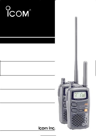
INSTRUCTION MANUAL
LPD FM HANDHELD TRANSCEIVER
i4088E

FOREWORD
Thank you for purchasing the IC-4088E LPD (Low Power Device) FM transceiver. This LPD FM transceiver meets the European LPD specification (EN 300 220). This transceiver is designed for those who require top-grade quality, performance and outstanding reliability under the most demanding conditions.
D FEATURES
Free of user-license and applications
Voice scrambler function for communication privacy
External DC-IN jack for both operation and battery charging
(Optional BC-149D or CP-18E is required)
All 69 LPD channels are available
38 convenient group channels
■ ATS (Automatic Transponder System)
This convenient function automatically checks station availability within the operating range, and alerts you via function display indication. (p. 20)
In addition, a manual transponder is also available for “GROUP MODE” operation to check availability of stations in a specified group within the operating range. In this case, the transceiver alerts you via beeps. (p. 15)
■ WEATHER-RESISTANT* CONSTRUCTION
Weather-resistant* construction is employed, and this unit can be used in a wide range of applications.
*Meets JIS water-protection specification grade 4.
i
■ GROUP MODE (BUILT-IN CTCSS: Continuous Tone
Coded Squelch System)
CTCSS encoder/decoder are standard, providing quiet stand-by. Audio (voice) signals are output only when a signal with matched CTCSS tone signal is received. This is very helpful for group communications. In addition, 38 different CTCSS frequencies are available. (p. 12)
■ 2 types of “Ring” function
The “Smart-Ring” function and the “Call-Ring” function are available for smart and simple station calls providing a telephonestyle ring when called. 10 different ringing tones are available. (p. 18)
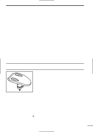
SUPPLIED ACCESSORY
• Belt clip ………………………………… 1
Icom, Icom Inc. and the 
 are registered trademarks of Icom Incorporated (Japan) in the United States, the United Kingdom, Germany, France, Spain, Russia and/or other countries.
ii

IMPORTANT
READ ALL INSTRUCTIONS carefully and completely before using the transceiver.
SAVE THIS INSTRUCTION MANUAL— This instruction manual contains important operating instructions for the transceiver.
PRECAUTION
RWARNING! NEVER hold the transceiver so that the antenna is very close to, or touching exposed parts of the body, especially the face or eyes, while transmitting. The transceiver will perform best if the microphone is 5 to 10 cm away and the transceiver is vertical.
RWARNING! NEVER operate the transceiver with a headset or other audio accessories at high volume levels. Hearing experts advise against continuous high volume operation. If you experience a ringing in your ears, reduce the volume or discontinue use.
NEVER attempt to charge alkaline cell batteries. Be aware that external DC power connections will charge batteries inside the battery case. This will damage not only the battery case but also the transceiver.
DO NOT push the PTT when not actually desiring to transmit.
iii

PRECAUTION— continued
USE the optional AC adapter or cigarette lighter cable only for both operating the transceiver and charging the battery. Other manufacturer’s AC adapter, cigarette lighter cable or DC power cable with external power supply may damage the transceiver.
Place the unit in a secure place to avoid inadvertent use by children.
DO NOT operate the transceiver near unshielded electrical blasting caps or in an explosive atmosphere.
AVOID using or placing the transceiver in direct sunlight or in areas with temperatures below –10°C or above +55°C.
The use of non-Icom battery packs/chargers may impair transceiver performance and invalidate the warranty.
Even when the transceiver power is OFF, a slight current still flows in the radio. Remove the alkaline battery cells or battery pack from the transceiver when not using it for a long time. Otherwise, the installed batteries will become exhausted.
When the battery voltage becomes below 3.24 V, the performance of the transceiver cannot be guaranteed due to the regulation.
iv

TABLE OF CONTENTS
FOREWORD …………………………………………………………………… i SUPPLIED ACCESSORY……………………………………………………… ii IMPORTANT …………………………………………………………………… iii PRECAUTION ……………………………………………………………… iii–iv TABLE OF CONTENTS ……………………………………………………… v
1 PREPARATION …………………………………………………………… 1
■Belt clip attachment ……………………………………………………… 1
■Battery installation ……………………………………………………… 1
2 PANEL DESCRIPTION ………………………………………………… 2–4
■Switches, controls, keys and connectors ……………………………… 2
■Function display ………………………………………………………… 4
3 BATTERY CHARGING ………………………………………………… 5–7
■Battery caution …………………………………………………………… 5
■Charging connections …………………………………………………… 6
4 BASIC OPERATION …………………………………………………… 8–9
■Power ON ………………………………………………………………… 8
■Adjusting the volume …………………………………………………… 8
■Selecting the operating channel………………………………………… 9
5RECEIVE AND TRANSMIT ………………………………………… 10–11
6GROUP MODE (CTCSS) …………………………………………… 12–13
■Setting the group code ………………………………………………… 12
7SCAN FUNCTION ………………………………………………………… 14
8RING FUNCTIONS ……………………………………………………… 15
■Smart-Ring ……………………………………………………………… 15
■Call-Ring ………………………………………………………………… 15
9OTHER FUNCTIONS ………………………………………………… 16–21
■Voice scrambler function ……………………………………………… 16
■Initial set mode ………………………………………………………… 16
■Lock function …………………………………………………………… 19
■Low battery indicator …………………………………………………… 19
■Auto power save………………………………………………………… 19
■ATS (Automatic Transponder System) ……………………………… 20
■Resetting the transceiver ……………………………………………… 20
■Optional HM-75A functions …………………………………………… 21
10SPECIFICATIONS …………………………………………………… 22–23
11OPTIONS…………………………………………………………………… 24
12CE …………………………………………………………………………… 25
v
BATTERY PACK
|
PREPARATION |
1 |
|
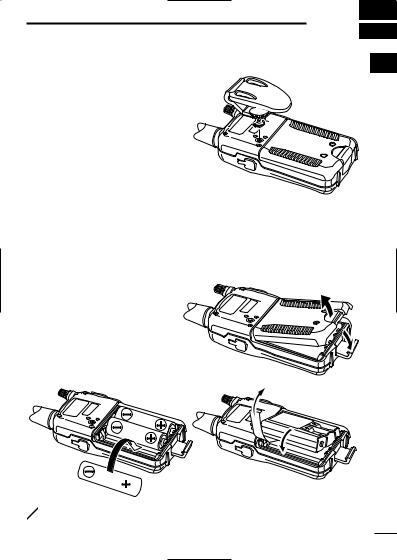
■ Belt clip attachment |
1 |
Attach the belt clip using the supplied screw. Conveniently attaches to a belt.
■ Battery installation
Install 3 R6 (AA) size alkaline cell batteries or the optional BP-202 as illustrated below.
qRemove the battery case cover from the transceiver. wInstall 3×R6 (AA) size alkaline cell batteries or BP-
202.
• Be sure to observe the correct polarity.
BP-202

 Alkaline cells
 NOTE: Keep battery contacts clean. It’s good idea to clean bat-
  tery terminals once a week.
1
2 PANEL DESCRIPTION
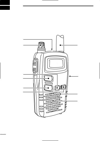
■Switches, controls, keys and connectors
q
 Function e
 display
(p. 4)
|
r |
i |
|
|
t |
||
|
y |
||
|
u |
Microphone |
|
|
Speaker |
2

PANEL DESCRIPTION 2
q EXTERNAL SPEAKER AND MICROPHONE JACKS
Connect an optional speaker-microphone or headset, if desired.
2
w VOLUME CONTROL [VOL]
Rotate clockwise to increase and counterclockwise to decrease volume.
e PTT SWITCH [PTT]
Push and hold to transmit; release to receive.
r MODE SWITCH [MODE]
Push to enter and select set mode for group (p. 12) and voice scrambler code. (p. 16)
Push and hold for 1 sec. to turn the monitor function ON and OFF. (p. 
t CHANNEL UP SWITCH [Y]
Push to increment the operating channel.
Push and hold to increment the operating channel continuously.
While scanning, changes scanning direction. (p. 14)
y CHANNEL DOWN SWITCH [Z]
Push to decrement the operating channel.
Push and hold to decrement the operating channel continuously.
While scanning, changes scanning direction. (p. 14)
u POWER SWITCH [PWR]
Push to turn the power ON.
Push and hold this key to toggle the key lock function ON/OFF. (p. 19)
iEXTERNAL DC IN JACK [DC 6V] (p. 6)
Connects the optional AC adapter or cigarette lighter cable for both operation and battery charging.
3
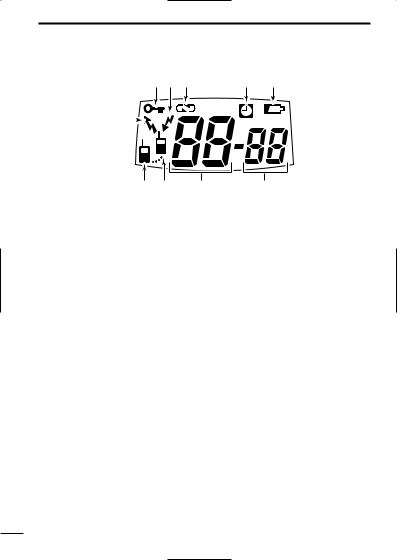
2 PANEL DESCRIPTION
■ Function display
q KEY LOCK INDICATOR
Appears during the key lock function ON. w BUSY INDICATOR
Appears while receiving a signal or when the squelch is open. e VOICE SCRAMBLER INDICATOR
Appears while the voice scrambler function is in use. r AUTO POWER OFF INDICATOR
Appears while the auto power off function is ON. t LOW BATTERY INDICATOR
Appears or blinks when the battery decreases to a specified level. y GROUP NUMBER INDICATOR
Indicates the selected group number during the group function ON. u CHANNEL NUMBER INDICATOR
Indicates the selected operating channel number. i POWER ON INDICATOR
Appears while the power is ON. o ANSWER BACK INDICATOR
Appears when you and your group are in the conversation area.
Blinks when you or your group is out of the conversation area.
!0TRANSMIT INDICATOR
Appears during PTT ON.
4
 Loading…
Similar Devices: DJ-100, OmniSwitch 6250, IC-F6122DD
-
1OPERATION GUIDETJ5A is a high sensibility, high-performance portable multi-band SSB/CW transceiver, used withDDS as LO, offering wide frequency coverage and fine tuning rate. A signal of 0.1uV isdiscernible with this transceiver. The Doubly Balanced Diode Ring Mixer makes strong signalhandling capability possible.Features:Low RX current DrainHigh-Performanc …
TJ5A, 13
-
ZXC10 CBTScdma2000 Compact Base Transceiver Station Technical ManualVersion 1.0ZTE CORPORATION ZTE Plaza, Keji Road South, Hi-Tech Industrial Park, Nanshan District, Shenzhen, P. R. China 518057 Tel: (86) 755 26771900 800-9830-9830 Fax: (86) 755 26772236 URL: http://support.zte.com.cn E-mail: [email protected] …
ZXC10 CBTS O1, 73
-
Technical SpecificationsEthernet2 x Ethernet ports, RJ 45 Connectors.10 BaseTUTP category 3,4 or 5 cable up to 328ft/100m (2 pairs)100 BaseTXUTP category 5 cable up to 328ft/100m (2 pairs)1000 BaseTXUTP category 5 cable up to 164ft/50m (4 pairs)Auto detect bit rate (10/100/1000), or force to 10Mbit for each port (selectable)Automatic crossover detection or …
yellobrik OET 1540, 2
-
AM/FM/SSB/CW 6 Meter Amateur Mobile Transceiver Owner’s Manual RCI-5054DX / RCI-5054DX -100 — 1 — Table of Contents PAGE Chapter 1 Specifications ………………………………………………. 2 Chapter 2 Introduction …………………………………………………. 3 Unpacking ………………………….. …
RCI-5054DX-100, 11
-
© 2003-11 PRINTED IN JAPANB51-8667-00 (N) 694HF / 50MHz ALL MODE TRANSCEIVERTS-480HX/480SATSERVICE MANUALDISASSEMBLY FOR REPAIR ……………………………. 2CIRCUIT DESCRIPTION ……………………………………. 3COMPONENTS DESCRIPTION ……………………….. 14SEMICONDUCTOR DATA ………………………………. 20PARTS LIST . …
TS-480HX, 158
-
A BELDEN BrandCopperHead™3400Series 3000 Camera-Mountable ENG/EFP Fiber OpticTransceiver SystemUser ManualPRELIMINARYTelecast Fiber Systems, Inc.102 Grove StreetWorcester, MA 01605Tel: 508-754-4858Fax: 508-752-1520www.telecast-fiber.com …
CopperHead 3400, 102