
-
Драйверы
13
-
Инструкции по эксплуатации
6
Языки:

ASUS P5G41T-M LX2/GB/LPT инструкция по эксплуатации
(58 страниц)
- Языки:Английский
-
Тип:
PDF -
Размер:
2.64 MB -
Описание:
P5G41T-M user’s manual (English)
Просмотр

ASUS P5G41T-M LX2/GB/LPT инструкция по эксплуатации
(60 страниц)
- Языки:Немецкий
-
Тип:
PDF -
Размер:
3.74 MB -
Описание:
P5G41T-M user’s manual (German)
Просмотр

ASUS P5G41T-M LX2/GB/LPT инструкция по эксплуатации
(58 страниц)
- Языки:Японский
-
Тип:
PDF -
Размер:
2.84 MB -
Описание:
P5G41T-M user’s manual (Japanese)
Просмотр

ASUS P5G41T-M LX2/GB/LPT инструкция по эксплуатации
(59 страниц)
- Языки:Французский
-
Тип:
PDF -
Размер:
2.61 MB -
Описание:
P5G41T-M user’s manual (French)
Просмотр

ASUS P5G41T-M LX2/GB/LPT инструкция по эксплуатации
(58 страниц)
- Языки:Китайский
-
Тип:
PDF -
Размер:
2.96 MB -
Описание:
P5G41T-M user’s manual (Traditional Chinese)
Просмотр

ASUS P5G41T-M LX2/GB/LPT инструкция по эксплуатации
(27 страниц)
-
Тип:
PDF -
Размер:
3.39 MB -
Описание:
P5G41T-M Asian Quick Start Guide for Multiple Languages
Просмотр
На NoDevice можно скачать инструкцию по эксплуатации для ASUS P5G41T-M LX2/GB/LPT. Руководство пользователя необходимо для ознакомления с правилами установки и эксплуатации ASUS P5G41T-M LX2/GB/LPT. Инструкции по использованию помогут правильно настроить ASUS P5G41T-M LX2/GB/LPT, исправить ошибки и выявить неполадки.
Manuals.eu
- Manuals.eu
- ASUS
- Computers & Peripherals
- Motherboards
- Socket775
- P5G41T-M LX2/GB
Free Manuals for ASUS P5G41T-M LX2/GB

Manufacturer:ASUS
Category:Computers & Peripherals
Device:ASUS P5G41T-M LX2/GB
Name:P5G41T-M LX2 Series user’s manual (English)
Language:English
Version:E5226
Pages:40
Size:1.44 MB
DescriptionP5G41T-M LX2 Series user’s manual (English)View ASUS P5G41T-M LX2/GB P5G41T-M LX2 Series user’s manual (English) E5226 (English)
×
Copyright © Manuals.eu
Agreement
Privacy Policy
Contact us
![]()
P5G41T-M LX2/BR
Motherboard

E5212
First Edition V1
December 2009
Copyright © 2009 ASUSTeK Computer Inc. All Rights Reserved.
No part of this manual, including the products and software described in it, may be reproduced, transmitted, transcribed, stored in a retrieval system, or translated into any language in any form or by any means, except documentation kept by the purchaser for backup purposes, without the express written permission of ASUSTeK Computer Inc. (“ASUS”).
Product warranty or service will not be extended if: (1) the product is repaired, modified or altered, unless such repair, modification of alteration is authorized in writing by ASUS; or (2) the serial number of the product is defaced or missing.
ASUS PROVIDES THIS MANUAL “AS IS” WITHOUT WARRANTY OF ANY KIND, EITHER EXPRESS OR IMPLIED, INCLUDING BUT NOT LIMITED TO THE IMPLIED WARRANTIES OR CONDITIONS OF MERCHANTABILITY OR FITNESS FOR A PARTICULAR PURPOSE. IN NO EVENT SHALL ASUS, ITS DIRECTORS, OFFICERS, EMPLOYEES OR AGENTS BE LIABLE FOR ANY INDIRECT, SPECIAL, INCIDENTAL, OR CONSEQUENTIAL DAMAGES (INCLUDING DAMAGES FOR LOSS OF PROFITS, LOSS OF BUSINESS, LOSS OF USE OR DATA, INTERRUPTION OF BUSINESS AND THE LIKE), EVEN IF ASUS HAS BEEN ADVISED OF THE POSSIBILITY OF SUCH DAMAGES ARISING FROM ANY DEFECT OR ERROR IN THIS MANUAL OR PRODUCT.
SPECIFICATIONS AND INFORMATION CONTAINED IN THIS MANUAL ARE FURNISHED FOR INFORMATIONAL USE ONLY, AND ARE SUBJECT TO CHANGE AT ANY TIME WITHOUT NOTICE, AND SHOULD NOT BE CONSTRUED AS A COMMITMENT BY ASUS. ASUS ASSUMES NO RESPONSIBILITY OR LIABILITY FOR ANY ERRORS OR INACCURACIES THAT MAY APPEAR IN THIS MANUAL, INCLUDING THE PRODUCTS AND SOFTWARE DESCRIBED IN IT.
Products and corporate names appearing in this manual may or may not be registered trademarks or copyrights of their respective companies, and are used only for identification or explanation and to the owners’ benefit, without intent to infringe.
Offer to Provide Source Code of Certain Software
This product may contain copyrighted software that is licensed under the General Public License (“GPL”) and under the Lesser General Public License Version (“LGPL”). The GPL and LGPL licensed code in this product is distributed without any warranty. Copies of these licenses are included in this product.
You may obtain the complete corresponding source code (as defined in the GPL) for the GPL Software, and/or the complete corresponding source code of the LGPL Software (with the complete machinereadable “work that uses the Library”) for a period of three years after our last shipment of the product including the GPL Software and/or LGPL Software, which will be no earlier than December 1, 2011, either
(1)for free by downloading it from http://support.asus.com/download;
or
(2)for the cost of reproduction and shipment, which is dependent on the preferred carrier and the location where you want to have it shipped to, by sending a request to:
ASUSTeK Computer Inc.
Legal Compliance Dept. 15 Li Te Rd.,
Beitou, Taipei 112 Taiwan
In your request please provide the name, model number and version, as stated in the About Box of the product for which you wish to obtain the corresponding source code and your contact details so that we can coordinate the terms and cost of shipment with you.
The source code will be distributed WITHOUT ANY WARRANTY and licensed under the same license as the corresponding binary/object code.
This offer is valid to anyone in receipt of this information.
ASUSTeK is eager to duly provide complete source code as required under various Free Open Source Software licenses. If however you encounter any problems in obtaining the full corresponding source code we would be much obliged if you give us a notification to the email address gpl@asus.com, stating the product and describing the problem (please do NOT send large attachments such as source code archives etc to this email address).
ii

Contents
|
Notices……………………………………………………………………………………………. |
v |
|
Safety information…………………………………………………………………………… |
vi |
|
About this guide……………………………………………………………………………… |
vi |
|
P5G41T-M LX2/BR specifications summary……………………………………. |
viii |
|
Chapter 1: |
Product introduction |
||
|
1.1 |
Before you proceed……………………………………………………………. |
1-1 |
|
|
1.2 |
Motherboard overview……………………………………………………….. |
1-2 |
|
|
1.2.1 |
Motherboard layout …………………………………………………. |
1-2 |
|
|
1.2.2 |
Layout contents . …………………………………………………….. |
1-2 |
|
|
1.3 |
Central Processing Unit (CPU)……………………………………………. |
1-3 |
|
|
1.4 |
System memory…………………………………………………………………. |
1-3 |
|
|
1.4.1 |
Overview ……………………………………………………………….. |
1-3 |
|
|
1.4.2 |
Memory configurations . …………………………………………… |
1-4 |
|
|
1.5 |
Expansion slots…………………………………………………………………. |
1-5 |
|
|
1.5.1 |
Installing an expansion card …………………………………….. |
1-5 |
|
|
1.5.2 |
Configuring an expansion card …………………………………. |
1-5 |
|
|
1.5.3 |
PCI slots . ………………………………………………………………. |
1-5 |
|
|
1.5.4 |
PCI Express x1 slot . ……………………………………………….. |
1-5 |
|
|
1.5.5 |
PCI Express x16 slot . ……………………………………………… |
1-5 |
|
|
1.6 |
Jumpers |
…………………………………………………………………………….. |
1-6 |
|
1.7 |
Connectors………………………………………………………………………… |
1-8 |
|
|
1.7.1 …………………………………………………….. |
Rear panel ports |
1-8 |
|
|
1.7.2 …………………………………………………. |
Internal connectors |
1-9 |
|
|
1.8 |
Software ………………………………………………………………support |
1-15 |
|
|
1.8.1 ………………………………… |
Installing an operating system |
1-15 |
|
|
1.8.2 ……………………………………….. |
Support DVD information |
1-15 |
|
|
1.8.3 ……………………………………………… |
ASUS Express Gate |
1-16 |
|
Chapter 2: |
BIOS information |
||
|
2.1 |
Managing and updating your BIOS……………………………………… |
2-1 |
|
|
2.1.1 |
ASUS Update utility………………………………………………… |
2-1 |
|
|
2.1.2 ASUS EZ Flash 2…………………………………………………… |
2-2 |
||
|
2.1.3 |
ASUS CrashFree BIOS.………………………………………….. |
2-3 |
|
|
2.2 |
BIOS setup program…………………………………………………………… |
2-3 |
iii

Contents
|
2.3 |
Main menu…………………………………………………………………………. |
2-4 |
|
|
2.3.1 |
System Time………………………………………………………….. |
2-4 |
|
|
2.3.2 |
System Date………………………………………………………….. |
2-4 |
|
|
2.3.3 |
Primary IDE Master/Slave, SATA1~4.……………………….. |
2-4 |
|
|
2.3.4 |
Storage Configuration……………………………………………… |
2-5 |
|
|
2.3.5 |
System Information…………………………………………………. |
2-6 |
|
|
2.4 |
Advanced menu…………………………………………………………………. |
2-6 |
|
|
2.4.1 |
CPU Configuration………………………………………………….. |
2-7 |
|
|
2.4.2 |
Chipset…………………………………………………………………. |
2-8 |
|
|
2.4.3 |
Onboard Devices Configuration……………………………….. |
2-9 |
|
|
2.4.4 |
USB Configuration………………………………………………….. |
2-9 |
|
|
2.4.5 |
PCI PnP………………………………………………………………. |
2-10 |
|
|
2.5 |
Power menu…………………………………………………………………….. |
2-10 |
|
|
2.5.1 |
Suspend Mode…………………………………………………….. |
2-10 |
|
|
2.5.2 |
ACPI 2.0 Support………………………………………………….. |
2-10 |
|
|
2.5.3 |
ACPI APIC Support………………………………………………. |
2-10 |
|
|
2.5.4 |
APM Configuration………………………………………………… |
2-11 |
|
|
2.5.5 |
Hardware Monitor………………………………………………….. |
2-11 |
|
|
2.6 |
Boot menu……………………………………………………………………….. |
2-12 |
|
|
2.6.1 |
Boot Device Priority………………………………………………. |
2-12 |
|
|
2.6.2 |
Boot Settings Configuration……………………………………. |
2-12 |
|
|
2.6.3 |
Security……………………………………………………………….. |
2-13 |
|
|
2.7 |
Tools menu………………………………………………………………………. |
2-14 |
|
|
2.7.1 |
ASUS EZ Flash 2…………………………………………………. |
2-14 |
|
|
2.7.2 |
Express Gate……………………………………………………….. |
2-14 |
|
|
2.8 |
Exit menu…………………………………………………………………………. |
2-15 |
iv
Notices
Federal Communications Commission Statement
This device complies with Part 15 of the FCC Rules. Operation is subject to the following two conditions:
•This device may not cause harmful interference, and
•This device must accept any interference received including interference that may cause undesired operation.
This equipment has been tested and found to comply with the limits for a Class B digital device, pursuant to Part 15 of the FCC Rules. These limits are designed to provide reasonable protection against harmful interference in a residential installation. This equipment generates, uses and can radiate radio frequency energy and, if not installed and used in accordance with manufacturer’s instructions, may cause harmful interference to radio communications. However, there is no guarantee that interference will not occur in a particular installation. If this equipment does cause harmful interference to radio or
television reception, which can be determined by turning the equipment off and on, the user is encouraged to try to correct the interference by one or more of the following measures:
•Reorient or relocate the receiving antenna.
•Increase the separation between the equipment and receiver.
•Connect the equipment to an outlet on a circuit different from that to which the receiver is connected.
•Consult the dealer or an experienced radio/TV technician for help.
The use of shielded cables for connection of the monitor to the graphics card is required to assure compliance with FCC regulations. Changes or modifications to this unit not expressly approved by the party responsible for compliance could void the user’s authority to operate this equipment.
Canadian Department of Communications Statement
This digital apparatus does not exceed the Class B limits for radio noise emissions from digital apparatus set out in the Radio Interference Regulations of the Canadian Department of Communications.
This class B digital apparatus complies with Canadian ICES-003.
REACH
Complying with the REACH (Registration, Evaluation, Authorisation, and Restriction of Chemicals) regulatory framework, we published the chemical substances in our products at ASUS REACH website at http://green.asus.com/english/REACH.htm.
DO NOT throw the motherboard in municipal waste. This product has been designed to enable proper reuse of parts and recycling. This symbol of the crossed out wheeled bin indicates that the product (electrical and electronic equipment) should not be placed in municipal waste. Check local regulations for disposal of electronic products.
DO NOT throw the mercury-containing button cell battery in municipal waste. This symbol of the crossed out wheeled bin indicates that the battery should not be placed in municipal waste.

Safety information
Electrical safety
•To prevent electric shock hazard, disconnect the power cable from the electric outlet before relocating the system.
•When adding or removing devices to or from the system, ensure that the power cables for the devices are unplugged before the signal cables are connected. If possible, disconnect all power cables from the existing system before you add a device.
•Before connecting or removing signal cables from the motherboard, ensure that all power cables are unplugged.
•Seek professional assistance before using an adapter or extension cord. These devices could interrupt the grounding circuit.
•Ensure that your power supply is set to the correct voltage in your area. If you are not sure about the voltage of the electrical outlet you are using, contact your local power company.
•If the power supply is broken, do not try to fix it by yourself. Contact a qualified service technician or your retailer.
Operation safety
•Before installing the motherboard and adding devices on it, carefully read all the manuals that came with the package.
•Before using the product, ensure that all cables are correctly connected and the power cables are not damaged. If you detect any damage, contact your dealer immediately.
•To avoid short circuits, keep paper clips, screws, and staples away from connectors, slots, sockets and circuitry.
•Avoid dust, humidity, and temperature extremes. Do not place the product in any area where it may become wet.
•Place the product on a stable surface.
•If you encounter technical problems with the product, contact a qualified service technician or your retailer.
About this guide
This user guide contains the information you need when installing and configuring the motherboard.
How this guide is organized
This guide contains the following parts:
•Chapter 1: Product introduction
This chapter describes the features of the motherboard and the new technology it supports.
•Chapter 2: BIOS information
This chapter tells how to change system settings through the BIOS Setup menus. Detailed descriptions of the BIOS parameters are also provided.
vi
Conventions used in this guide
To ensure that you perform certain tasks properly, take note of the following symbols used throughout this manual.
DANGER/WARNING: Information to prevent injury to yourself when trying to complete a task.
CAUTION: Information to prevent damage to the components when trying to complete a task.
IMPORTANT: Instructions that you MUST follow to complete a task.
NOTE: Tips and additional information to help you complete a task.
Where to find more information
Refer to the following sources for additional information and for product and software updates.
1.ASUS websites
The ASUS website provides updated information on ASUS hardware and software products. Refer to the ASUS contact information.
2.Optional documentation
Your product package may include optional documentation, such as warranty flyers, that may have been added by your dealer. These documents are not part of the standard package.
Typography
|
Bold text |
Indicates a menu or an item to select. |
|
Italics |
Used to emphasize a word or a phrase. |
|
<Key> |
Keys enclosed in the less-than and greater-than sign means |
|
that you must press the enclosed key. |
|
|
Example: <Enter> means that you must press the Enter or |
|
|
Return key. |
|
|
<Key1>+<Key2>+<Key3> |
If you must press two or more keys simultaneously, the key |
|
names are linked with a plus sign (+). |
|
|
Example: <Ctrl>+<Alt>+<D> |
vii

P5G41T-M LX2/BR specifications summary
|
CPU |
LGA775 socket for Intel® Core™2 Quad / Core™2 Extreme |
|
/ Core™2 Duo / Pentium® dual-core |
|
|
/ Celeron® dual-core / Celeron® processors |
|
|
Supports Intel® 45nm multi-core CPU |
|
|
Supports Intel® Hyper-Threading Technology and |
|
|
Enhanced Intel SpeedStep® Technology (EIST) |
|
|
* Refer to www.asus.com for the Intel® CPU support list. |
|
|
Chipset |
Northbridge: Intel® G41 |
|
Southbridge: Intel® ICH7 |
Front Side Bus
Memory
Graphics
Expansion slots
Storage
LAN
Audio
USB
1333/1066/800 MHz
Dual channel memory architecture
—2 x 240-pin DIMM sockets support unbuffered non-ECC 1066/800 MHz DDR3 memory modules
—Supports up to 8GB system memory
*Refer to www.asus.com for the latest Memory QVL
(Qualified Vendors Lists).
**When you install a total memory of 4GB or more, Windows® 32-bit operating system may only recognize less than 3GB. We recommend a maximum of 3GB system memory if you are using a Windows® 32-bit operating system.
Integrated Intel® Graphics Media Accelerator (Intel® GMA 4500)
Supports max. shared memory of 1759MB
Supports RGB with max. resolution of 2048 x 1536 x 32Bpp @ 75HZ
Supports Microsoft® DirectX 10
1 x PCIe x16 slot
1 x PCIe x1 slot
2 x PCI slots
1 x Ultra DMA 100/66 connector
4 x Serial ATA 3Gb/s ports
Realtek® RTL8112L Gigabit Ethernet PCIe controller
VIA® VT1705 High Definition Audio 6-channel CODEC
Supports Multi-streaming technology
Supports up to 8 USB 2.0/1.1 ports (4 ports at mid-board, 4 ports at the back panel)
(continued on the next page)
viii

P5G41T-M LX2/BR specifications summary
Back panel I/O ports
Internal connectors
ASUS unique features
BIOS
Manageability
Support DVD
Accessories
Form factor
1 x PS/2 keyboard port
1 x PS/2 mouse port
1 x COM port
1 x VGA port
1 x LAN (RJ-45) port
4 x USB 2.0/1.1 ports
1 x LPT port
6-channel audio ports
2 USB 2.0/1.1 connectors support additional 4 USB 2.0/1.1 ports
1 x IDE connector
4 x Serial ATA connectors
1 x High definition front panel audio connector
1 x System panel connector
1 x CD audio-in connector
1 x CPU fan connector
1 x Chassis fan connector
1 x 24-pin EATX power connector
1 x 4-pin ATX 12V power connector
1 x Chassis intrusion connector
ASUS CrashFree BIOS 3
ASUS Q-Fan
ASUS EZ Flash 2
ASUS MyLogo 2
ASUS Express Gate
8Mb Flash ROM, AMI BIOS, PnP, DMI 2.0, WfM 2.0, ACPI 2.0a, SM BIOS 2.5
WOL, PXE, PME Wake up, WOR by Ring
Drivers
ASUS PC Probe II
ASUS Update
Anti-Virus software (OEM version)
2 x Serial ATA cables
1 x Ultra DMA 100/66 cable
1 x I/O shield
1 x Support DVD
1 x User Manual
MicroATX form factor: 9.6 in x 7.5 in (24.4 cm x 19.1 cm)
* Specifications are subject to change without notice.
ix

Chapter 1
Product introduction
Thank you for buying an ASUS® P5G41T-M LX2/BR motherboard!
Before you start installing the motherboard, and hardware devices on it, check the items in your motherboard package. Refer to page ix for the list of accessories.
If any of the items is damaged or missing, contact your retailer.
1.1Before you proceed
Take note of the following precautions before you install motherboard components or change any motherboard settings.
• Unplug the power cord from the wall socket before touching any component.
•Before handling components, use a grounded wrist strap or touch a safely grounded object or a metal object, such as the power supply case, to avoid damaging them due to static electricity.
•Hold components by the edges to avoid touching the ICs on them.
•Whenever you uninstall any component, place it on a grounded antistatic pad or in the bag that came with the component.
•Before you install or remove any component, ensure that the ATX power supply is switched off or the power cord is detached from the power supply. Failure to do so may cause severe damage to the motherboard, peripherals, or components.
Onboard LED
The motherboard comes with a standby power LED that lights up to indicate that the system is ON, in sleep mode, or in soft-off mode. This is a reminder that you must shut down
the system and unplug the power cable before removing or plugging in any motherboard component. The illustration below shows the location of the onboard LED.
SB_PWR
P5G41T-M LX2/BR
ON OFF
Standby Power Powered Off
P5G41T-M LX2/BR Onboard power LED

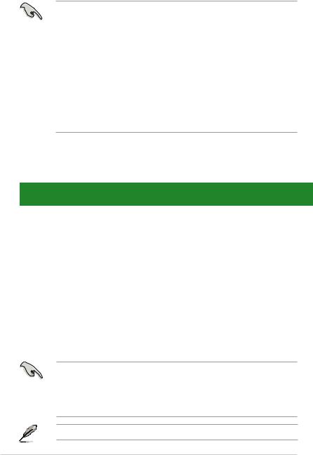
1.2Motherboard overview
1.2.1Motherboard layout
Ensure that you install the motherboard into the chassis in the correct orientation. The edge with external ports goes to the rear part of the chassis.
Place this side towards the rear of the chassis.
16
|
1 |
2 |
3 |
4 |
5 |
6 |
19.1cm(7.5in)
KBMS KBPWR
ATX12V
COM1
|
LPT |
||
|
VGA |
CHA_FAN |
|
|
CPU_FAN |
||
|
USB34 |
||
|
USBPW1-4 |
||
|
LAN1_USB12 |
RTL |
|
|
8112L |
|
DDR3 DIMM A1 (64bit, 240-pin module) |
DDR3 DIMM B1 (64bit, 240-pin module) |
|
ICS |
2 |
|||||
|
AUDIO |
9LPRS441 |
|||||
|
EATXPWR |
||||||
|
PCIEX1_1 |
Lithium Cell |
|||||
|
CMOS Power |
||||||
|
Super |
PCIEX16 |
|||||
|
I/O |
||||||
|
P5G41T-M LX2/BR |
||||||
|
SATA4 |
||||||
|
SATA3 |
8Mb |
|||||
|
PCI1 |
Intel® |
SATA2 |
BIOS |
|||
|
SATA1 |
||||||
|
ICH7 |
||||||
|
VIA |
CD |
PCI2 |
8 |
|||
|
VT1705 |
SB_PWR |
|||||
|
USB56 USB78 |
||||||
|
USBPW5-8 |
||||||
|
CLRTC |
|
15 |
14 |
4 |
13 |
12 |
11 |
10 |
9 |
Place six screws into the holes indicated by circles to secure the motherboard to the chassis. DO NOT overtighten the screws! Doing so can damage the motherboard.
1.2.2Layout contents
|
Connectors/Jumpers/Slots/LED |
Page |
Connectors/Jumpers/Slots/LED |
Page |
||||
|
1. |
Keyboard power (3-pin KBPWR) |
1-7 |
9. |
System panel connector (10-1 pin F_PANEL) |
1-14 |
||
|
2. |
ATX power connectors (24-pin EATXPWR, 4-pin ATX12V) |
1-9 |
10. |
Clear RTC RAM (3-pin CLRTC) |
1-6 |
||
|
3. |
CPU and Chassis fan connectors (4-pin CPU_FAN and |
1-10 |
11. |
USB connectors (10-1 pin USB56, USB78) |
1-12 |
||
|
3-pin CHA_FAN) |
|||||||
|
4. |
USB device wake-up (3-pin USBPW1-4, USBPW5-8) |
1-7 |
12. |
Standby power LED (SB_PWR) |
1-1 |
||
|
5. |
LGA775 CPU socket |
1-3 |
13. |
Chassis intrusion connector |
1-13 |
||
|
(4-1 pin CHASSIS) |
|||||||
|
6. |
DDR3 DIMM slots |
1-3 |
14. |
Optical drive audio connector (4-pin CD) |
1-11 |
||
|
7. |
IDE connector (40-1 pin PRI_IDE) |
1-11 |
15. |
Front panel audio connector (10-1 pin AAFP) |
1-13 |
||
|
8. |
SATA connectors (7-pin SATA1-4) |
1-10 |
16. |
PCIe x16 / PCIe x1 / PCI slots |
1-5 |
||
|
Chapter 1: Product introduction |
1-2 |
1.3Central Processing Unit (CPU)
This motherboard comes with a surface mount LGA775 socket designed for the Intel® Core™2 Quad / Core™2 Extreme / Core™2 Duo / Pentium® dual-core / Celeron® dual-core / Celeron® processors.
• Upon purchase of the motherboard, ensure that the PnP cap is on the socket and the socket contacts are not bent. Contact your retailer immediately if the PnP cap is missing, or if you see any damage to the PnP cap/socket contacts/motherboard components. ASUS will shoulder the cost of repair only if the damage is shipment/transit-related.
•Keep the cap after installing the motherboard. ASUS will process Return Merchandise
Authorization (RMA) requests only if the motherboard comes with the cap on the
LGA775 socket.
•The product warranty does not cover damage to the socket contacts resulting from incorrect CPU installation/removal, or misplacement/loss/incorrect removal of the PnP cap.
The motherboard supports Intel® LGA775 processors with the Intel® Enhanced Intel SpeedStep® Technology (EIST) and Hyper-Threading Technology.
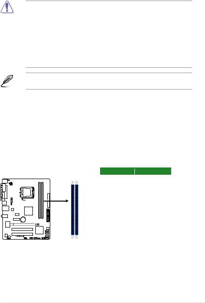
1.4System memory
1.4.1Overview
This motherboard comes with two Double Data Rate 3 (DDR3) Dual Inline Memory Modules (DIMM) sockets. A DDR3 module has the same physical dimensions as a DDR2 DIMM but is notched differently to prevent installation on a DDR2 DIMM socket. DDR3 modules are developed for better performance with less power consumption. The figure illustrates the location of the DDR3 DIMM sockets:
DIMM_A1 DIMM_B1
|
Channel |
Sockets |
|
Channel A |
DIMM_A1 |
|
Channel B |
DIMM_B1 |
P5G41T-M LX2/BR
P5G41T-M LX2/BR 240-pin DDR3 DIMM sockets
1.4.2Memory configurations
You may install 512MB, 1GB, 2GB, and 4GB unbuffered non ECC DDR3 DIMMs into the DIMM sockets.
• You may install varying memory sizes in Channel A and Channel B. The system maps the total size of the lower-sized channel for the dual-channel configuration. Any excess memory from the higher-sized channel is then mapped for single-channel operation.
•Always install DIMMs with the same CAS latency. For optimum compatibility, it is recommended that you obtain memory modules from the same vendor.
•Due to the memory address limitation on 32-bit Windows® OS, when you install 4GB or more memory on the motherboard, the actual usable memory for the OS can be about 3GB or less. For effective use of memory, we recommend that you do either of the following:
—Use a maximum of 3GB system memory if you are using a 32-bit Windows® OS.
—Install a 64-bit Windows® OS when you want to install 4GB or more memory on the motherboard.
•This motherboard does not support DIMMs made up of 256 megabits (Mb) chips or less.
P5G41T-M LX2/BR Motherboard Qualified Vendors Lists (QVL)
DDR3-1066MHz capability
|
SS/ |
Chip |
Timing |
DIMM |
|||||||
|
support |
||||||||||
|
Vendor |
Part No. |
Size |
Chip NO. |
Dimm |
Voltage |
|||||
|
DS |
Brand |
|||||||||
|
(Bios) |
A* |
B* |
||||||||
|
Crucial |
CT12864BA1067.8FF |
1024MB |
SS |
Micron |
9GF22D9KPT |
7 |
• |
• |
||
|
Crucial |
CT25664BA1067.16FF |
2048MB |
DS |
Micron |
9HF22D9KPT |
7 |
• |
• |
||
|
Elpida |
EBJ51UD8BAFA-AC-E |
512MB |
SS |
Elpida |
J5308BASE-AC-E |
• |
• |
|||
|
Elpida |
EBJ51UD8BAFA-AE-E |
512MB |
SS |
Elpida |
J5308BASE-AC-E |
• |
• |
|||
|
Elpida |
EBJ11UD8BAFA-AE-E |
1024MB |
DS |
Elpida |
J5308BASE-AC-E |
• |
• |
|||
|
Kingston |
KVR1066D3N7/1G |
1024MB |
SS |
Kingston |
D1288JEKAPGA7U |
7 |
1.5V |
• |
• |
|
|
Kingston |
KVR1066D3N7/2G |
2048MB |
DS |
Kingston |
D1288JEKAPGA7U |
7 |
1.5V |
• |
• |
|
|
Micron |
MT8JTF12864AY-1G1D1 |
1024MB |
SS |
Micron |
8ED22D9JNL |
• |
• |
|||
|
Micron |
MT8JTF12864AZ-1G1F1 |
1024MB |
SS |
Micron |
9GF22D9KPT |
7 |
• |
• |
||
|
Micron |
MT16JTF25664AY-1G1D1 |
2048MB |
DS |
Micron |
8LD22D9JNL |
• |
• |
|||
|
Micron |
MT16JTF25664AZ-1G1F1 |
2048MB |
DS |
Micron |
9HF22D9KPT |
7 |
• |
• |
||
|
OCZ |
OCZ3SOE10662GK |
2048MB(Kit of 2) |
DS |
N/A |
Heat-Sink Package |
7-7-7-16 |
1.75V |
• |
• |
|
|
SAMSUNG |
M378B2873EH1-CF8 |
1024MB |
SS |
Samsung |
SEC 901 HCF8 K4B1G0846E |
• |
• |
|||
|
SAMSUNG |
M378B5273BH1-CF8 |
4096MB |
DS |
SAMSUNG |
846 K4B2G0846B-HCF8 |
• |
• |
|||
|
Elixir |
M2Y2G64CBHA9N-BE |
2048MB |
DS |
N/A |
Heat-Sink Package |
7-7-7-20 |
• |
• |
||
|
Kingtiger |
2GB DIMM PC3-8500 |
2048MB |
DS |
Hynix |
H5TQ1G83AFP G7C |
• |
• |
SS: Single-sided / DS: Double-sided
DIMM support:
•A*: Supports one module inserted into either slot as Single-channel memory configuration.
•B*: Supports one pair of modules inserted into both slots as one pair of dual-channel memory configuration.
Visit the ASUS website at www.asus.com for the latest QVL.
|
Chapter 1: Product introduction |
1-4 |

1.5Expansion slots
In the future, you may need to install expansion cards. The following sub sections describe the slots and the expansion cards that they support.
Unplug the power cord before adding or removing expansion cards. Failure to do so may cause you physical injury and damage motherboard components.
1.5.1Installing an expansion card
To install an expansion card:
1.Before installing the expansion card, read the documentation that came with it and make the necessary hardware settings for the card.
2.Remove the system unit cover (if your motherboard is already installed in a chassis).
3.Remove the bracket opposite the slot that you intend to use. Keep the screw for later use.
4.Align the card connector with the slot and press firmly until the card is completely seated on the slot.
5.Secure the card to the chassis with the screw you removed earlier.
6.Replace the system cover.
1.5.2Configuring an expansion card
After installing the expansion card, configure it by adjusting the software settings.
1.Turn on the system and change the necessary BIOS settings, if any. See Chapter 2 for information on BIOS setup.
2.Assign an IRQ to the card.
3.Install the software drivers for the expansion card.
When using PCI cards on shared slots, ensure that the drivers support “Share IRQ” or that the cards do not need IRQ assignments. Otherwise, conflicts will arise between the two PCI groups, making the system unstable and the card inoperable.
1.5.3PCI slots
The PCI slot supports cards such as a LAN card, SCSI card, USB card, and other cards that comply with PCI specifications.
1.5.4PCI Express x1 slot
This motherboard supports PCI Express x1 network cards, SCSI cards, and other cards that comply with the PCI Express specifications.
1.5.5PCI Express x16 slot
This motherboard supports a PCI Express x16 graphics card that complies with the PCI
Express specifications.
 Loading…
Содержание
- P5g41t m lx2 gb куда подключать спикер
- Page 23: Chassis
- Этапы подключения передней панели к материнской плате
- Этап 1
- Этап 2
- Этап 3
- Этап 4
- Видео-инструкция по подключению фронтальной панели к «материнке»
- Страница 14: Asus p5g41-m lx, P5g41-m lx, Usbpw5-8, Usbpw1-4, Kbpwr
- Инструкция и руководство для Asus P5G41C-M LX на русском на испанском на французском на итальянском на чешском на немецком на польском
- Français Deutsh Italiano Español Русский Português Polski Če.
- Installer le cpu, Layout de la carte mère, Français
- Mémoire système, Français
- Informations du bios, Informations sur le dvd de support, Français
- Motherboard-layout 2. installieren der cpu, Deutsch, Asus p5g41c-m lx a b
Page 23: Chassis

Chapter 1: Product introduction
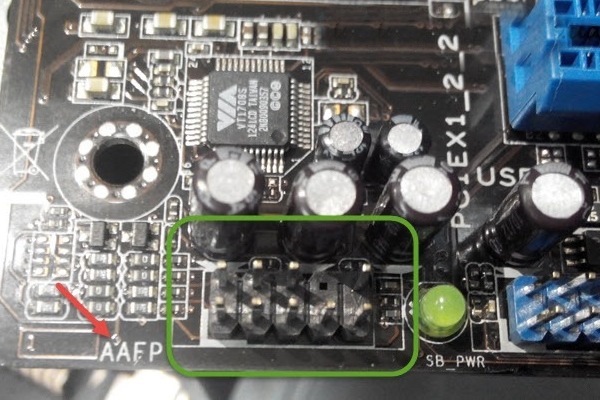
Front panel audio connector (10-1 pin AAFP)
This connector is for a chassis-mounted front panel audio I/O module that supports
either HD Audio or legacy AC`97 audio standard. Connect one end of the front panel
audio I/O module cable to this connector.
P5G41T-M LX2/GB/LPT Front panel audio connector
• We recommend that you connect a high-definition front panel audio module to this
connector to avail of the motherboard’s high-definition audio capability.
• If you want to connect a high-definition front panel audio module to this connector, set
the Front Panel Type item in the BIOS setup to [HD Audio]. If you want to connect an
AC’97 front panel audio module to this connector, set the item to [AC97]. By default, this
connector is set to [HD Audio]. See section 2.4.2 Chipset for details.
Chassis intrusion connector (4-1 pin CHASSIS)
This connector is for a chassis-mounted intrusion detection sensor or switch. Connect
one end of the chassis intrusion sensor or switch cable to this connector. The chassis
intrusion sensor or switch sends a high-level signal to this connector when a chassis
component is removed or replaced. The signal is then generated as a chassis intrusion
By default, the pins labeled “Chassis Signal” and “GND” are shorted with a jumper cap.
Remove the jumper caps only when you intend to use the chassis intrusion detection
P5G41T-M LX2/GB/LPT Chassis intrusion connector
The Chassis intrusion connector is an optional item for P5G41T-M LX2 and
Передняя панель на корпусе системного блока никак не связана с остальными «внутренностями» компьютера. Значит, при ручном отключении с целью чистки или, что немного сложнее, при замене материнской платы, придётся самостоятельно подключать фронтальную панель. Далее будет в подробностях рассказано, как сделать это максимально правильно.
Этапы подключения передней панели к материнской плате
Рассмотрим основные моменты в подключении фронтальной панели к «материнке»:
Этап 1
Первым делом необходимо найти основной шлейф с 4 (иногда 5-6) штекерами. Возможна некоторая разница в названиях, цвете и т. д.
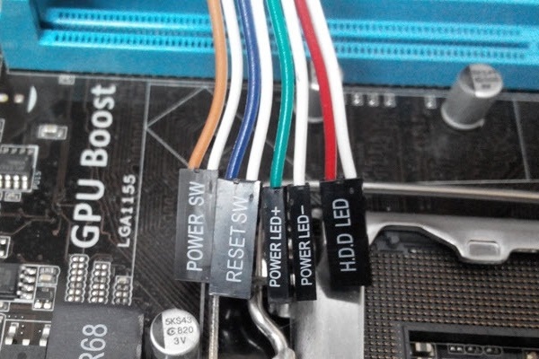
Расположенные на фото сверху штекеры подразумевают собой следующее:
- POWERSW (или PWRBTN) – активирует манипуляции с кнопкой включения/выключения компьютера на панели.
- H.D.D.LED (или HDLED) – лампочка, мигающая при работе жёсткого диска.
- POWERLED + и – (или PLED) – лампочка на кнопке включения/отключения компьютера; если компьютер работает, то горит, и наоборот; может быть цельным штекером.
- RESTARTSW (или RESET) – активирует кнопку перезагрузки компьютера.
- SPEAKER – небольшой динамик, издающий писк, если наблюдаются проблемы в работе компьютера.
Названия этих штекеров могут различаться, но не сильно. Например, вместо POWERSW может быть указано PW. А вместо RESTARTSW – просто RES. Сравнивая первые буквы названия штекеров и разъёмов, можно без труда понять, какой штекер куда должен подключаться. Также помогают цвета, которые, зачастую, соответствуют цвету кабелей от штекеров. Но в первую очередь нужно сравнивать именно названия, следом – цвета, ведь они могут различаться, в отличие от названий.
Этап 2
Вставлять штекеры необходимо в одно большое гнездо (FRONTPANEL или F_PANEL) на краю материнской платы. Обычно оно выглядит вот так:
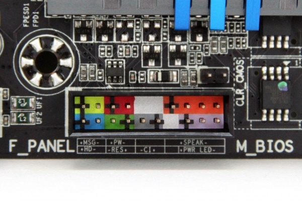
Чтобы подсоединить провода в разъёмы правильной стороной, можно просто посмотреть на сам штекер. Если в нём не будет хватать одного контакта (железная «спица»), то присоединять нужно этим местом, в соответствии с другим пустым местом на материнской плате, в разъёме. Также могут помочь боковые крепления на некоторых гнёздах и штекерах (крепления должны быть на одной стороне). Дополнительно можно ориентироваться по цветам в разъёме или визуальным подсказкам в виде блестящих контактов и т. п. Как правило, штекеры подсоединяются надписью «на себя» или в сторону надписей на материнской плате (схеме).
Внизу, под цветными разъёмами, схематично указаны (подписаны) места, куда нужно подключать штекеры. Например, согласно схеме под разъёмами, отвечающий за кнопку включения компьютера штекер (POWERSW) следует подсоединить в красное гнездо (второе слева, сверху, подписано как PW). Все остальные провода присоединяются в указанные на схеме места соответствующим образом.
В сопроводительной к компьютеру документации, если она имеется, также есть подсказки по подключению штекеров в гнёзда. Выглядят данные подсказки так:
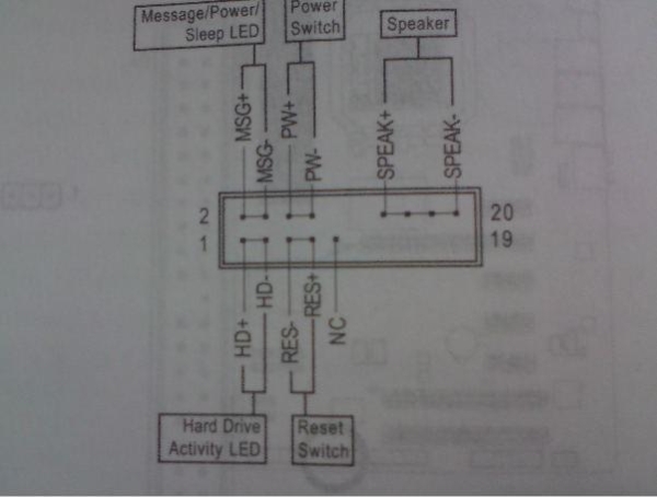
Как видно на рисунке, в документах даже расшифровываются названия штекеров и сокращений на схеме. Например, RES – ResetSwitch (рус. «кнопка перезагрузки») и т. д.
Этап 3
Штекеры, отвечающие за работу USB-портов на передней панели, подключаются чуть иначе и проще. Выглядит USB-штекер — вот так:
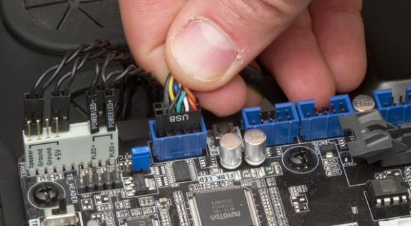
Разъём для данного штекера может иметь следующие названия:
- F_USB1/F_USB2;
- USB1/USB2;
- или все гнёзда для этого штекера могут называться просто USB.
Не имеет значения, куда будет подключаться провод, так как все USB-гнёзда полностью идентичны. За исключением USB 3.0. Если на передней панели имеется именно такой USB-штекер, то и разъём на материнской плате нужно искать с соответствующим названием. Зачастую именно так он и называется – USB 3.0, но могут быть и исключения в виде F_USB30 и т. д.
Этап 4
Подключение звука (наушники/микрофон) на фронтальной панели происходит идентично описанным ранее процессам.
Берётся штекер из передней панели с названием AC97 или HDAUDIO и вставляется в разъём с соответствующей надписью:
Если звук так и не появился, возможно, проблема кроется в BIOS. Перезагрузив компьютер и «попав» в систему BIOS, следует проверить фронтальную панель и её характеристики. Иногда бывает, что подключён штекер HDAUDIO, а BIOS распознал подключённое устройство как AC 97. Решается данный недочёт изменением в BIOSе неправильного драйвера на соответствующий подключённому в материнской плате.
Видео-инструкция по подключению фронтальной панели к «материнке»
В следующем видео на наглядном примере и во всех деталях объясняется процесс присоединения штекеров в разъёмы на материнской плате.
Страница 14: Asus p5g41-m lx, P5g41-m lx, Usbpw5-8, Usbpw1-4, Kbpwr

Формат материнской платы
Для установки процессора выполните следующее:
1.
Нажмите на удерживающий рычаг большим пальцем (А), затем перемещайте его влево
(В) до тех пор, пока он не высвободится из-под фиксирующего язычка.
Источник
Инструкция и руководство для
Asus P5G41C-M LX на русском на испанском на французском на итальянском на чешском на немецком на польском
41 страница подробных инструкций и пользовательских руководств по эксплуатации
Asus p5g41t-m lx2/gb + xeon e5450 — быстрый курс по установке ксеона 🙂
ОБЗОР МАТЕРИНСКОЙ ПЛАТЫ Asus p5g41t m lx2 v2
Материнская плата c AliExpress LGA 775 ddr3 ( Asus p5p41t le )
Разгон Xeon E5450 на Asus P5G41T-MLX
Asus P5G41C-M LX 775 Socket Anakarta & Xeon E5450 CPU (İŞLEMCİ) MONTAJ ve Yükleme
Asus P5G41C-M LX & XEON X5472 FSB1600 CPU UYARLAMA-MONTAJ YÜKLEME-BIOS
Asus P5G41C-M LX & Xeon X5460 CPU (3.16Ghz.) SYSTEM UPDATE
Asus P5G41C M LX Mother Board
Français Deutsh Italiano Español Русский Português Polski Če.
P5g41c-m lx, Motherboard, Quick start guide
Quick Start Guide
2010 ASUSTeK COMPUTER INC.
All Rights Reserved
Installer le cpu, Layout de la carte mère, Français
Asus p5g41c-m lx a b, F_panel, P5g41c-m lx, Usbpw5-8, Usbpw1-4, Kbpwr
ASUS P5G41C-M LX
Installer le CPU
Pour installer le CPU :
1. Pressez le levier avec votre pouce (A) et déplacez-le vers la gauche (B)
jusqu’à ce qu’il soit libéré de son onglet de rétention.
Layout de la carte mère
Ce côté doit être face à vous.
DDR3 DIMM_A1 (64bit, 240-pin module)
DDR2 DIMM_A1 (64bit, 240-pin module)
DDR3 DIMM_B1 (64bit, 240-pin module)
DDR2 DIMM_B1 (64bit, 240-pin module)

Mémoire système, Français
ASUS P5G41C-M LX
2. Soulevez le levier dans un angle de 135º.
3. Soulevez la plaque avec votre pouce et votre index à un angle de 100º, puis
enlevez le couvercle PnP de la plaque.
4. Placez le CPU sur le socket, en vous assurant que la marque en forme de
triangle doré est placée en bas à gauche du socket. Les ergots d’alignement
du socket doivent correspondre aux encoches du CPU.
5. Refermez la plaque, puis pressez le levier jusqu’à ce qu’il se loge dans le
loquet de rétention.
• Pour éviter d’endommager les broches du socket, ne retirez le couvercle
PnP que lors de l’installation d’un CPU.
• Veuillez garder le couvercle en cas de retour du produit.
• La garantie de ce produit ne couvre pas les dommages causés aux
broches du socket.
Vous pouvez installer des modules mémoire DDR3 non tamponnés et non ECC de
512Mo, 1Go, 2Go et 4Go dans les slots noirs ou des modules mémoire DDR2 non
tamponnés et non ECC de 512Mo, 1Go, 2Go et 4Go dans les slots bleus.
• N’utilisez pas des modules mémoire DDR3 et DDR2 simultanément.
• Vous pouvez installer des modules mémoire de tailles variables dans le
Canal A et B. Le système mappe la taille totale du canal de plus petite taille
pour les configurations dual-channel. Tout excédant de mémoire du canal
le plus grand est alors mappé pour fonctionner en single-channel.
• Installez toujours des modules mémoire avec une latence CAS identique.
Pour obtenir une compatibilité optimale, il vous est recommandé de vous
équiper des modules de mémoire auprès du même vendeur.
• En raison des limitations d’adressage mémoire sur les systèmes
d’exploitation Windows 32-bits, lorsque vous installez 4Go ou plus de
mémoire sur cette carte mère, le montant de mémoire utilisable par le
système d’exploitation sera de 3 Go ou moins. Pour une utilisation effective
de la mémoire, vous pouvez :
Utiliser un maximum de 3 Go lors de l’utilisation d’un système
Installer un système d’exploitation Windows 64-bits si vous souhaitez
installer 4 Go ou plus de mémoire sur cette carte mère.
• Cette carte mère ne supporte pas les modules mémoire composés de
puces mémoire de 256 Mo ou moins.
DDR3_A1 et DDR2_A1
DDR3_B1 et DDR2_B1

Informations du bios, Informations sur le dvd de support, Français
ASUS P5G41C-M LX
Informations du BIOS
Utilisez le programme de configuration du BIOS pour mettre à jour le BIOS ou
configurer ses paramètres. Les écrans BIOS comprennent les clés de navigation
et une courte aide en ligne pour vous guider. Si vous rencontrez des problèmes
liés au système ou si le système devient instable une fois que vous aurez modifié
les paramètres, chargez les Paramètres de Réglage Par Défaut. Rendez visite au
site web d’ASUS (www.asus.com) pour obtenir les mises à jour.
Pour accéder au Setup lors du démarrage:
Pressez lors du Test Automatique de Démarrage (POST : Power-On
Self Test ). Si vous ne pressez pas la touche , le POST continuera son
programme de test.
Pour accéder au programme de configuration du BIOS après le POST :
• Redémarrez le système en pressant + + , puis pressez
lors du POST, ou
• Pressez le bouton de réinitialisation situé sur le châssis puis pressez
lors du POST, ou
• Eteignez et rallumez le système puis pressez lors du POST.
Pour mettre à jour le BIOS avec ASUS EZ Flash 2 :
Démarrez le système et appuyez sur + lors du POST pour lancer EZ
Flash 2. Insérez un disque flash USB contenant le dernier fichier image du BIOS.
EZ Flash 2 lance le processus de mise à jour du BIOS et redémarre le système
automatiquement une fois terminé.
Pour restaurer le BIOS avec CrashFree BIOS 3 :
Démarrez le système. Si le BIOS est corrompu, l’outil de restauration automatique
CrashFree BIOS 3 vérifiera la présence du fichier du BIOS sur le lecteur optique
et le disque flash USB. Connectez un disque flash USB ou insérez le DVD de
support dans le lecteur optique contenant le dernier fichier image du BIOS ou celui
d’origine. Redémarrez le système une fois le processus de restauration du BIOS
Informations sur le DVD de support
Cette carte mère supporte les systèmes d’exploitation Windows
Installez toujours la dernière version d’OS et les mises à jour correspondantes de
manière à profiter pleinement des caractéristiques de votre matériel.
Le DVD de support livré avec la carte mère contient les pilotes, les applications
logicielles, et les utilitaires que vous pouvez installer pour tirer partie de toutes les
fonctions de la carte mère.
’Exécution automatique n’est pas activée sur votre ordinateur, parcourez
le contenu du DVD de support pour localiser le fichier ASSETUP.EXE dans le
répertoire BIN. Double-cliquez sur
ASSETUP.EXE pour lancer le DVD.

Motherboard-layout 2. installieren der cpu, Deutsch, Asus p5g41c-m lx a b
F_panel, P5g41c-m lx, Usbpw5-8, Usbpw1-4, Kbpwr
ASUS P5G41C-M LX
Installieren der CPU
So installieren Sie den Prozessor:
1. Drücken Sie den Arretierhebel mit Ihrem Daumen (A) und schieben Sie ihn nach
links (B), bis er vom Halteriegel losgelassen wird.
Источник