
-
Page 1
OM-222 166K 2007−11 Processes Induction Heating Description Induction Heating Power Source ProHeat 35 Visit our website at File: Induction Heating www.MillerWelds.com… -
Page 2
ISO 9001:2000 Quality System Standard. particular model are also provided. Miller Electric manufactures a full line of welders and welding related equipment. For information on other quality Miller products, contact your local Miller distributor to receive the latest full line catalog or individual specification sheets. -
Page 3: Table Of Contents
TABLE OF CONTENTS SECTION 1 − SAFETY PRECAUTIONS − READ BEFORE USING 1-1. Symbol Usage …………… . 1-2.
-
Page 4
TABLE OF CONTENTS 6-5. Run Status …………….6-5-1. -
Page 5
Declaration of Conformity for European Community (CE) Products This information is provided for units with CE certification (see rating label on unit). Manufacturer: Miller Electric Mg. Co. 1635 W. Spencer St. Appleton, WI 54914 USA Phone: (920) 734-9821 European Contact Signature:… -
Page 7: Section 1 − Safety Precautions − Read Before Using
SECTION 1 − SAFETY PRECAUTIONS − READ BEFORE USING Protect yourself and others from injury — read and follow these precautions. 1-1. Symbol Usage DANGER! − Indicates a hazardous situation which, if not avoided, will result in death or serious injury. The possible hazards are shown in the adjoining symbols or explained in the text.
-
Page 8: Additional Symbols For Installation, Operation, And Maintenance
FIRE OR EXPLOSION hazard. D Do not overheat parts. D Watch for fire; keep extinguisher nearby. D Keep flammables away from work area. Do not locate unit on, over, or near combustible surfaces. Do not install unit near flammables. Do not operate where the atmosphere may contain flammable dust, gas, or liquid vapors (such as gasoline).
-
Page 9: Principal Safety Standards
1-5. Principal Safety Standards Safety in Welding, Cutting, and Allied Processes, ANSI Standard Z49.1, from Global Engineering Documents (phone: 1-877-413-5184, website: www.global.ihs.com). OSHA, Occupational Safety and Health Standards for General Industry, Title 29, Code of Federal Regulations (CFR), Part 1910, Subpart Q, and Part 1926, Subpart J, from U.S.
-
Page 10: Section 2 − Consignes De Sécurité − Lire Avant Utilisation
SECTION 2 − CONSIGNES DE SÉCURITÉ − LIRE AVANT Se protéger, ainsi que toute autre personne travaillant sur les lieux, contre les étincelles et le métal chaud. 2-1. Signification des symboles DANGER! − Indique une situation dangereuse qui si on l’évite pas peut donner la mort ou des blessures graves.
-
Page 11: Dangers Supplémentaires En Relation Avec L’installation, Le Fonctionnement Et La Maintenance
À l’intérieur, ventiler la zone et/ou utiliser une ventilation forcée au niveau de l’arc pour l’évacuation des fumées et des gaz. Si la ventilation est médiocre, porter un respirateur anti-vapeurs ap- prouvé. Lire et comprendre les spécifications de sécurité des matériaux (MSDS) et les instructions du fabricant concernant les adhésifs, les flux, les métaux, les consommables, les revêtements, les nettoyants et les dégraisseurs.
-
Page 12: Proposition Californienne 65 Avertissements
LE RAYONNEMENT HAUTE FRÉ- QUENCE (HF) risque de provoquer des interférences. D Le rayonnement haute fréquence (HF) peut provoquer des interférences avec les équipe- ments de radio-navigation et de communication, les services de sécurité et les ordinateurs. Demander seulement à des personnes qualifiées familiarisées avec des équipements électroniques de faire fonctionner l’installa- tion.
-
Page 13: Section 3 − Definitions
SECTION 3 − DEFINITIONS 3-1. Warning Label Definitions Warning! Watch Out! There are possible hazards as shown by the symbols. Electric shock from wiring can kill. 1.1 Wear dry insulating gloves. Do not wear wet or damaged gloves. 1.2 Disconnect input plug or power before working on machine.
-
Page 14: Warning Label Definitions (Continued)
3-2. Warning Label Definitions (Continued) OM-222 166 Page 8 Warning! Watch Out! There are possible hazards as shown by the symbols. Electric shock from wiring can kill. Overuse can cause overheating. Follow rated duty cycle. Disconnect input plug or power before working on machine.
-
Page 15: Rating Label For Ce Products
3-3. Rating Label For CE Products For label location see Section 4-2. 226 534-B 3-4. WEEE Label (For Products Sold Within The EU) Do not discard product (where ap- plicable) with general waste. Reuse or recycle Waste Electrical and Electronic Equipment (WEEE) by disposing at a designated collec- tion facility.
-
Page 16: Symbols And Definitions
3-5. Symbols And Definitions Some symbols are found only on CE products. Amperes Degree Of Protection Increase Primary Voltage Rated Maximum Supply Current 1max 1max Remote SECTION 4 − INSTALLATION 4-1. Specifications Rated Output Output Frequency Frequency Single Dual Output Output 35 kW At 35 kW At…
-
Page 17: Selecting A Location
4-2. Selecting A Location Movement Location And Airflow 12 in (305 mm) 18 in (460 mm) 4-3. Tipping (460 mm) 12 in (305 mm) Lifting Eye Lifting Forks Use lifting eye or lifting forks to move unit. If using lifting forks, extend forks beyond opposite side of unit.
-
Page 18: Electrical Service Guide
4-4. Electrical Service Guide Failure to follow these electrical service guide recommendations could create an electric shock or fire hazard. These recommenda- tions are for a dedicated branch circuit sized for the rated output and duty cycle of the welding power source. Input Voltage Input Amperes At Rated Output Max Recommended Standard Fuse Or Circuit Breaker Rating In Amperes…
-
Page 19: Connecting 3-Phase Input Power For 460/575 Volt Models
4-5. Connecting 3-Phase Input Power For 460/575 Volt Models Tools Needed: 3/8 in GND/PE Earth Ground 803 994-C Installation must meet all National and Local Codes − have only quali- fied persons make this installation. Disconnect and lockout/tagout in- put power before connecting input conductors from unit.
-
Page 20: Connecting 3-Phase Input Power For 400/460 Volt Models
4-6. Connecting 3-Phase Input Power For 400/460 Volt Models Tools Needed: Installation must meet all National and Local Codes − have only qualified per- sons make this installation. Disconnect and lockout/tagout input power before connecting input con- ductors from unit. Make input power connections to the welding power source first.
-
Page 21: Power Source Output Connections
4-7. Power Source Output Connections Single Air-Cooled Output Connection Output Connector 1 Output Connector 2 Protective Plug Air-Cooled Extension Cable Liquid-Cooled Extension Cable The power source is capable of single or dual output. When connected for single power output, up to 35 kW is available at the single output connection.
-
Page 22: Remote 14 Receptacle Rc14 Information And Connections
4-8. Remote 14 Receptacle RC14 Information and Connections 4-9. Remote 14 Socket Information Socket Remote Contactor Remote Contactor Remote Output Control Remote Output Control F, J Power Source Limit Remote Metering Remote Metering OM-222 166 Page 16 C L N Socket Information +24 volts dc.
-
Page 23: Temperature Recorder Receptacle Rc9 Information And Connections
4-10. Temperature Recorder Receptacle RC9 Information And Connections 4-11. Temperature Recorder Socket Information Socket No. Socket Information Thermocouple No. 1 (TC1), 0-10 volt dc signal [0V = −50° F (−46° C), 10V = 1500° F (816° C)] Thermocouple No. 2 (TC2), 0-10 volt dc signal [0V = −50° F (−46° C), 10V = 1500° F (816° C)] Thermocouple No.
-
Page 24: Secondary Insulation Protection
4-12. Secondary Insulation Protection OM-222 166 Page 18 Secondary insulation protection circuitry automatically shuts down the power source output if a potentially hazardous condition exists heating device connected to the power source (e.g. insulation has broken down on a heating blanket causing conductor to come into contact with…
-
Page 25: 115 Volt Ac Duplex Receptacle And Supplementary Protector
4-13. 115 Volt AC Duplex Receptacle And Supplementary Protector 4-14. Locating Thermocouples Thermocouple location is one of the most critical steps in the Heat Treatment Operation. Thermocouples shall be located as follows to provide a survey of heating uniformly and enable time and temperature control: Locate thermocouples to ensure that the full area of the heat band is monitored.
-
Page 26
The following describes the thermocouple routing from work to power source. Type K thermocouple wire (two wire) is attached directly to the workpiece using a Thermocouple Attachment Unit (see next section for information on attaching thermocouples). The other end is fitted with a 2-pin type K connector. The 2-pin connector plugs into the 3-pin composite extension cable. -
Page 27: Attaching Welded Thermocouples
4-15. Attaching Welded Thermocouples Do NOT weld thermocouples while connected to power source. Attach thermocouples using a portable Thermocouple Attachment Unit (TAU). This unit spot welds thermocouple wire directly to the workpiece. This method of thermocouple attachment ensures accurate temperature measurement. Clean (file or grind) any loose scale or rust from the workpiece at the places where the wires will be attached.
-
Page 28: Using Contact Thermocouples
4-16. Using Contact Thermocouples The welded thermocouples discussed previously can be used for preheating or stress relieving. As an alternative, in preheating applications, a contact temperature sensor* can be used. This eliminates the need to weld thermocouples and the sensor can be moved during the preheat process to check temperatures at other locations on the joint.
-
Page 29: Section 5 − Components And Controls
SECTION 5 − COMPONENTS AND CONTROLS 5-1. Controls When a control panel button is pushed the yellow lamp lights to indicate ac- tivation. Power Switch Use switch to turn power source On and Off. TC1−4 Temperature Display Provides temperature display of thermo- couples 1 through 4.
-
Page 30: Section 6 − Setup And Operation
Designed to provide a single level of output (up to 35 kW), the ProHeat 35 power source has two panel mounted connectors that are connected in parallel to the power source output. This design allows the system to operate with either a single output extension cable or two output extension cables.
-
Page 31
Possible selections: Degree Units: °F / °C Tolerance: ±5 to 99 in °F (±3 to 55 in °C) Backlight: Yes / No Input Type: K TC Control Mode: Temp / Time / Manual Power Output: 1 to 35 System Lock: Yes / No Degree Units −… -
Page 32: Programming
To reset the system back to factory default settings, turn off the power source, and wait until the display goes blank. Turn on the power source. When the display lights, press and hold the Increase defaults. Release the Increase 6-4. Programming Programming allows the operator to setup a program for a particular heating process.
-
Page 33: Bake-Out
6-4-1-2. Bake-Out The bake-out process allows the operator to program a temperature and soak time as well as a cooling rate from bake-out if desired. When this process is selected, the following screen appears on the display: Mode…: Bake−Out Control TC:>1 Soak Temp.: Cool Temp.: The default position of the cursor is next to Control TC.
-
Page 34: Custom Program
The default position of the cursor is next to Control TC. Press the Increase thermocouples to be used for the program. Selections are as follows: 1, 1,2, 1,2,3, or 1,2,3,4. TC1 MUST always be a control thermocouple. TC2 thru TC4 can be used for controlling or monitoring. When a thermocouple is selected as control, the LED adjacent to the seven-segment display illuminates.
-
Page 35
Mode…: Custom Program Segment…: Type…: End Control TC.: 1 The default position of the cursor is next to Segment. Press the Increase segment number, unless the segment type is End. In this case, the segment number will advance to segment 1. Use the Cursor button to move the cursor to the desired selection (Type or Control TC), and press the Increase button to change the value to the desired setting. -
Page 36
Mode…: Custom Program Segment…: Type…: Ramp Temperature: Use the Cursor button to move the cursor to the Temperature or Ramp Rate position and use the Increase button to set the desired value. When the cursor is in the Ramp Rate position, pressing the Cursor number. -
Page 37
Soak Function When type is set to Soak, the following screen appears on the display: Mode…: Custom Program Segment…: Type…:>Soak Soak Time..: 00:01:00 Use the Cursor button to move the cursor to the Soak Time position and use the Increase the desired value. -
Page 38: Manual Control
Typical 5-Segment Custom Program Mode…: Custom Program Segment…: Type…:>Step Temperature: Temperature increases to 600 degrees at full-programmed power. Mode…: Custom Program Segment…: Type…: Ramp Temperature:>1250 Controlled heating to 1250 degrees F at a ramp of 600 degrees per hour. Mode…: Custom Program Segment…: Type…: Soak Soak Time..:>01:00:00…
-
Page 39: Run Status
Mode…: Manual Command.: Run Time: 00:03:00 The only programmable selections are Command power and Run Time. Command can be adjusted to deliver up to 35 KW (based on maximum power selected in the set-up screen) for a period of up to 99 hours, 59 minutes, 59 seconds. Power source operating power, current, voltage, and frequency are shown on the right-hand side of the display.
-
Page 40: Manual Control
6-5-2. Manual Control Mode…: Manual Power…: Countdown: −−:−−:−− Status…: Stopped During active operation, Power shows the actual power delivered from the power source, Countdown shows the time remaining in the heating cycle, and Status indicates if the system is running or stopped. TC5 and TC6 display the temperature of thermocouples 5 and 6. This screen is for monitoring purposes only.
-
Page 41: Real-Time Operation
Firmware Revision X.XX Copyright (c) 2005 Miller Electric Mfg. Co. X.XX indicates the firmware revision number installed in the unit. If an error is detected during the check routine, the system fault LED illuminates and an error message screen appears on the display (see Section 9-5).
-
Page 42
In addition, when running in Manual operating mode, the Hold pressing the Hold button will cause the following screen to appear on the display: Hold mode not available when temperature control is not active Pressing the Hold button will activate the hold function while running a temperature controlled program. While in the hold mode, the parame- ters for the program in process can be modified. -
Page 43: System Operating Characteristics
6-9. System Operating Characteristics The power source delivers a high-frequency alternating current output that energizes the coil creating the magnetic field used to heat the workpiece. The power source output characteristics are a function of the configuration, type and number of coils used as shown in the following table: Table 6-1.
-
Page 44: Section 7 − Maintenance
SECTION 7 − MAINTENANCE 7-1. Routine Maintenance n = Check Z = Change * To be done by Factory Authorized Service Agent Every Months l Damaged or Unreadable ~ Output Connector Con- Labels tacts n Integrity Of Protective nlCracked Cables Plug, Replace If Necessary Every Months…
-
Page 45: Section 8 − Safety Precautions For Servicing
SECTION 8 − SAFETY PRECAUTIONS FOR SERVICING Protect yourself and others from injury — read and follow these precautions. 8-1. Symbol Usage DANGER! − Indicates a hazardous situation which, if not avoided, will result in death or serious injury. The possible hazards are shown in the adjoining symbols or explained in the text.
-
Page 46: California Proposition 65 Warnings
MOVING PARTS can cause injury. D Keep away from moving parts such as fans. D Have only qualified persons remove doors, panels, covers, or guards for maintenance as necessary. D Keep hands, hair, loose clothing, and tools away from moving parts.
-
Page 47: Section 9 − Diagnostics & Troubleshooting
SECTION 9 − DIAGNOSTICS & TROUBLESHOOTING The ProHeat 35 power source has on-board capabilities to aid in troubleshooting problems should any conditions occur during operation. This troubleshooting capability consists of the Fault LED, Limit LED, and message screens that appear on the front panel LCD display.
-
Page 48: Limit Conditions
9-2. Limit Conditions A limit condition indicates that the system has encountered an open thermocouple or is outside the range of its optimum operating conditions or parameters. Should a limit condition occur during operation, the yellow Limit LED will flash to indicate a problem. If the active screen on the LCD display is Run Status or Parameters, a message describing the particular limit condition will appear on the display.
-
Page 49: Fault Conditions
Limit Condition L11: Coolant Overtemp Limit L12: Power Source Overtemp Limit L13:Cable Connection 9-4. Fault Conditions A fault condition occurs if the system encounters an isolation fault, encounters operating conditions outside operational limits, or if there is a serious problem with the system. Should a fault condition occur, the output is immediately turned off, the red Fault LED flashes and the Stop LED flashes.
-
Page 50: System Diagnostic Screens
Fault Condition F67: Over Frequency Fault F68: Cable Connection Fault F69: Coolant Overtemp Fault F70: Internal Communication Fault F71: Internal Thermistor Fault F72: Coolant Thermistor Fault F73: Decoupled/Open Coil F74: Isolation Fault Self-Test Error F75: Internal Power Supply Fault F76: Current Source Control Fault F77: Power Source Internal Comm Fault F78:Output Current Sense Fault 9-6.
-
Page 51
OPEN − no cable or plug in place ClntFR − This is the coolant flow rate (in GPM) from the cooler on a liquid-cooled system. ClrSts − This is the status of the cooler. Possible labels: Flowing The second diagnostic screen is available by again pressing and holding the Run Status button. -
Page 52: Removing Wrapper And Measuring Input Capacitor Voltage
9-7. Removing Wrapper and Measuring Input Capacitor Voltage Tools Needed: 5/16, 3/8 in + lead to right bus terminal, − lead to left bus terminal OM-222 166 Page 46 Typical Bleeder Resistor 200 to 500 ohm, 10 watt wire wound resistor #16 AWG 600 Volts AC 900 Volts dc can be present on the capacitor bus and…
-
Page 53
9-8. Blowing Out Inside Of Unit Notes Turn Off welding power source and disconnect input power. Remove wrapper and be sure input capacitors are discharged. Blow out inside of unit. Blow out fan motors in right side panel and front panel. -
Page 54: Section 10 − Electrical Diagram
SECTION 10 − ELECTRICAL DIAGRAM Figure 10-1. Circuit Diagram OM-222 166 Page 48…
-
Page 55
218 057-G OM-222 166 Page 49… -
Page 56: Section 11 − Parts List
SECTION 11 − PARTS LIST See Figure 11-2 Item Dia. Part Mkgs….+217 470 ….217 860 .
-
Page 57
……….. NAMEPLATE, ProHeat 35 . -
Page 58
Hardware is common and not available unless listed. Item Dia. Part Mkgs….217 324 … 174 207 . -
Page 59
Hardware is common and not available unless listed. Item Dia. Part Mkgs….217 328 ….213 865 . -
Page 60
Hardware is common and not available unless listed. Item Dia. Part Mkgs….218 424 ….218 684 . -
Page 61
Hardware is common and not available unless listed. Item Dia. Part Mkgs..C3-C6 ..218 685 ….218 688 . -
Page 62
Hardware is common and not available unless listed. Item Dia. Part Mkgs….216 630 ….213 873 . -
Page 63
Item Dia. Part Mkgs….229 728 ….216 262 . -
Page 64
Hardware is common and not available unless listed. Figure 11-8. Right Windtunnel (400 V Model Only) Item Dia. Part Mkgs….216 630 .. -
Page 65
Item Dia. Part Mkgs….208 591 ….229 728 . -
Page 66
Hardware is common and not available unless listed. Item Dia. Part Mkgs….216 631 ….218 683 . -
Page 67
Item Dia. Part Mkgs..PLG16, 121,122 . . . 131 054 ..PLG19, ..115 094 ..PLG15, . -
Page 68
Hardware is common and not available unless listed. Item Dia. Part Mkgs….221 440 ….221 443 . -
Page 69
Notes SOCKET/WRENCH SELECTION TABLE (U.S. STANDARD) Specifications Socket or Wrench Size Bolt Decimal Bolt Diameter Equivalent 1/4 in .250 in 3/8 in 5/16 in .3125 in 1/2 in 3/8 in .375 in 9/16 in 7/16 in .4375 in 5/8 in 1/2 in .500 in 3/4 in… -
Page 70
Notes OM-222 166 Page 64… -
Page 71
Warranty Questions? LIMITED WARRANTY − Subject to the terms and conditions Call below, Miller Electric Mfg. Co., Appleton, Wisconsin, warrants to 1-800-4-A-MILLER its original retail purchaser that new Miller equipment sold after the effective date of this limited warranty is free of defects in for your local material and workmanship at the time it is shipped by Miller. -
Page 72
For assistance in filing or settling claims, contact your distributor and/or equipment manufacturer’s Transportation Department. © 2007 Miller Electric Mfg. Co. 2007−01 Miller Electric Mfg. Co. An Illinois Tool Works Company 1635 West Spencer Street Appleton, WI 54914 USA International Headquarters−USA…
-
Страница 1
ProHeat 35 Processes Description Induction Heating Power Source Induction Heating OM-222 166K 2007 − 11 File: Induction Heating V isit our website at www.MillerWelds.com[…]
-
Страница 2
Miller Electric manufactures a full line of welders and welding related equipment. For information on other quality Miller products, contact your local Miller distributor to receive the latest full line catalog or individual specification sheets. T o locate your nearest distributor or service agency call 1-800-4-A-Miller , or visit us at www .Mille[…]
-
Страница 3
T ABLE OF CONTENTS SECTION 1 − SAFETY PRECAUTIONS − READ BEFORE USING 1 . . . . . . . . . . . . . . . . . . . . . . . . . . . . . . . . . . 1-1. Symbol Usage 1 . . . . . . . . . . . . . . . . . . . . . . . . . . . . . . . . . . . . . . . . . . . . . . . . . . . . . . . . . . . . . . . . . . . . . . . . 1-2. Induction Heating Hazards 1 . . . . .[…]
-
Страница 4
T ABLE OF CONTENTS 6-5. Run Status 33 . . . . . . . . . . . . . . . . . . . . . . . . . . . . . . . . . . . . . . . . . . . . . . . . . . . . . . . . . . . . . . . . . . . . . . . . . . . 6-5-1. T emperature Based Control 33 . . . . . . . . . . . . . . . . . . . . . . . . . . . . . . . . . . . . . . . . . . . . . . . . . . . . . . . . . . 6-5-1-1. […]
-
Страница 5
dec_stat_1/07 Declaration of Conformity for European Community (CE) Products . This information is provided for units with CE certification (see rating label on unit). Manufacturer : European Contact: Miller Electric Mg. Co. Mr . Danilo Fedolfi, 1635 W . Spencer St. Managing Director Appleton, WI 54914 USA ITW Welding Products Italy S.r .l. Phone: […]
-
Страница 6
[…]
-
Страница 7
OM-222 166 Page 1 SECTION 1 − SAFETY PRECAUTIONS − READ BEFORE USING ihom _2007 − 04 Protect yourself and others from injury — read and follow these precautions. 1-1. Symbol Usage DANGER! − Indicates a hazardous situation which, if not avoided, will result in death or serious injury . The possible hazards are shown in the adjoining symbol[…]
-
Страница 8
OM-222 166 Page 2 FIRE OR EXPLOSION hazard. D Do not overheat parts. D W atch for fire; keep extinguisher nearby . D Keep flammables away from work area. D Do not locate unit on, over , or near combustible surfaces. D Do not install unit near flammables. D Do not operate where the atmosphere may contain flammable dust, gas, or liquid vapors (such a[…]
-
Страница 9
OM-222 166 Page 3 1-5. Principal Safety Standards Safety i n W elding, Cutting, and Allied Processes, ANSI Standard Z49.1, from Global Engineering Documents (phone: 1-877-413-5184, website: www .global.ihs.com). OSHA, Occupational Safety and Health Standards for General Industry , T itle 29, Code of Federal Regulations (CFR), Part 1910, Subpart Q, […]
-
Страница 10
OM-222 166 Page 4 SECTION 2 − CONSIGNES DE SÉCURITÉ − LIRE A V ANT UTILISA TION ihom _2007 − 04fre Se protéger , ainsi que toute autre personne travaillant sur les lieux, contre les étincelles et le métal chaud. 2-1. Signification des symboles DANGER! − Indique une situation dangereuse qui si on l’évite pas peut donner la mort ou de[…]
-
Страница 11
OM-222 166 Page 5 D À l’intérieur , ventiler la zone et/ou utiliser une ventilation forcée au niveau de l’arc pour l’évacuation des fumées et des gaz. D Si la ventilation est médiocre, porter un respirateur anti-vapeurs ap- prouvé. D Lire et comprendre les spécifications de sécurité des matériaux (MSDS) e t les instructions du fabr[…]
-
Страница 12
OM-222 166 Page 6 LE RA YONNEMENT HAUTE FRÉ- QUENCE (HF) risque de provoquer des interférences. D Le rayonnement haute fréquence (HF) peut provoquer des interférences avec les équipe- ments de r a d io — n a vi g a t i on e t de c o m mu ni c a t i on , l e s se rv i ce s de sécurité et les ordinateurs. D Demander seulement à des personnes […]
-
Страница 13
OM-222 166 Page 7 SECTION 3 − DEFINITIONS 3-1. W arning Label Definitions W arning! W atch Out! There are possible hazards as shown by the symbols. 1 Electric shock from wiring can kill. 1.1 Wear dry insulating gloves. Do not wear wet or damaged gloves. 1.2 Disconnect input plug or power before working on machine. 2 Induction heating can cause in[…]
-
Страница 14
OM-222 166 Page 8 3-2. W arning Label Definitions (Continued) 1 W arning! W atch Out! There are possible hazards as shown by the symbols. 2 Electric shock from wiring can kill. 3 Overuse can cause overheating. Follow rated duty cycle. 4 Disconnect input plug or power before working on machine. 5 Become trained and read the instructions before worki[…]
-
Страница 15
OM-222 166 Page 9 226 534-B 3-3. Rating Label For CE Products . For label location see Section 4-2. 3-4. WEEE Label (For Products Sold Within The EU) Do not discard product (where ap- plicable) with general waste. Reuse or recycle W aste Electrical and Electronic Equipment (WEEE) by disposing at a designated collec- tion facility . Contact your loc[…]
-
Страница 16
OM-222 166 Page 10 3-5. Symbols And Definitions . Some symbols are found only on CE products. A Amperes V V olts Alternating Current X Duty Cycle IP Degree Of Protection Hz Hertz Circuit Protection Output Increase Line Connection I 1 Primary Current I 2 Rated Current U 1 Primary V oltage U 2 Load V oltage Read Instructions Three Phase Static Freque[…]
-
Страница 17
OM-222 166 Page 1 1 4-2. Selecting A Location 1 Lifting Eye 2 Lifting Forks Use lifting eye or lifting forks to move unit. If using lifting forks, extend forks beyond opposite side of unit. 3 Rating Label (Non CE Models Only) Use rating label to determine input power needs. Label located under front access door . 4 Plate Label (CE Models Only) Labe[…]
-
Страница 18
OM-222 166 Page 12 4-4. Electrical Service Guide Failure to follow these electrical service guide recommendations could create an electric shock or fire hazard. These recommenda- tions are for a dedicated branch circuit sized for the rated output and duty cycle of the welding power source. 50 Hz Three Phase 60 Hz Three Phase Input V oltage 400 460 […]
-
Страница 19
OM-222 166 Page 13 4-5. Connecting 3-Phase Input Power For 460/575 V olt Models 803 994-C 3/8 in T ools Needed: ! Installation must meet all National an d Local Codes − have only quali- fied persons make this installation. ! Disconnect and lockout/tagout in- put power before connecting input conductors from unit. ! Make input power connections to[…]
-
Страница 20
OM-222 166 Page 14 Ref. 804 430-A T ools Needed: 4-6. Connecting 3-Phase Input Power For 400/460 V olt Models 3/8 in ! Installation must meet all National and Local Codes − have only qualified per- sons make this installation. ! Disconnect and lockout/tagout input power before connecting input con- ductors from unit. ! Make input power connection[…]
-
Страница 21
OM-222 166 Page 15 Ref. 803 993-C / Ref. 804 217-A 4-7. Power Source Output Connections 1 Output Connector 1 2 Output Connector 2 3 Protective Plug 4 Air-Cooled Extension Cable 5 Liquid-Cooled Extension Cable The power source is capable of single or dual output. When connected for single power output, up to 35 kW is available at the single output c[…]
-
Страница 22
OM-222 166 Page 16 803 993-C 4-8. Remote 14 Receptacle RC14 Information and Connections 1 Plug 2 Threaded Collar 3 Keyway 4 Remote 14 Receptacle RC14 (See Section 4-9) T o connect to receptacle, align key- way , insert plug and tighten threaded collar . AJ B K I C L NH D M G E F 3 4 2 1 1 2 4-9. Remote 14 Socket Information Socket Socket Informatio[…]
-
Страница 23
OM-222 166 Page 17 803 993-C 4-10. T emperature Recorder Receptacle RC9 Information And Connections 1 Plug 2 Threaded Collar 3 T emperature Recorder Receptacle RC9 (See Section 4-1 1) T o connect to receptacle, insert plug and tighten threaded collar . 3 2 1 1 2 4-1 1. T emperature Recorder Socket Information Socket No. Socket Information 1 Thermoc[…]
-
Страница 24
OM-222 166 Page 18 803 994-B / Ref. 801 826-C / Ref. 801 828-C 4-12. Secondary Insulation Protection Secondary insulation protection circuitry automatically shuts down the power source output if a potentially hazardous condition exists at the heating device connected to the power source (e.g. insulation has broken down on a heating blanket causing […]
-
Страница 25
OM-222 166 Page 19 803 993-C 4-13. 1 15 V olt AC Duplex Receptacle And Supplementary Protector 1 1 15 V AC 2.5 A Single-Phase AC Receptacle RC1 2 Supplementary Protector CB1 (2.5 A) Th e receptacle supplies nominal 1 15 volts ac auxiliary power for use with the optional digital recorder . Maxi- mum output from receptacle is 2.5 amperes. CB1 protect[…]
-
Страница 26
OM-222 166 Page 20 9. The following describes the thermocouple routing from work to power source. S T ype K thermocouple wire (two wire) is attached directly to the workpiece using a Thermocouple Attachment Unit (see next section for information on attaching thermocouples). S The other end is fitted with a 2-pin type K connector . S The 2-pin conne[…]
-
Страница 27
OM-222 166 Page 21 4-15. Attaching Welded Thermocouples . Do NOT weld thermocouples while connected to power source. 1. Attach thermocouples using a portable Thermocouple Attachment Unit (TAU). This unit spot welds thermocouple wire directly to the workpiece. This method of thermocouple attachment ensures accurate temperature measurement. 2. Clean […]
-
Страница 28
OM-222 166 Page 22 4-16. Using Contact Thermocouples Th e welded thermocouples discussed previously can be used for preheating or stress relieving. As an alternative, in preheating applications, a contact temperature sensor* can be used. This eliminates the need to weld thermocouples and the sensor can be moved during the preheat process to check t[…]
-
Страница 29
OM-222 166 Page 23 SECTION 5 − COMPONENTS AND CONTROLS 5-1. Controls . When a control panel button is pushed the yellow lamp lights to indicate ac- tivation. 1 Power Switch Use switch to turn power source On and Of f. 2 TC1 − 4 T emperature Display Provides temperature display of thermo- couples 1 through 4. 3 Control Thermocouple LED’s LED?[…]
-
Страница 30
OM-222 166 Page 24 SECTION 6 − SETUP AND OPERA TION 6-1. Safety Equipment W ear the following during operation: 1 Dry, Insulating Gloves 2 Safety Glasses With Side Shields DO NOT wear rings or watches during operation. sb3.1* 1/94 12 6-2. System Description Th e ProHeat 35 Induction Heating Power Source is designed to function either as an air-co[…]
-
Страница 31
OM-222 166 Page 25 Possible selections: Degree Units: ° F / ° C T olerance: ± 5 to 99 in ° F ( ± 3 to 55 in ° C) Backlight: Y es / No Input T ype: K TC Control Mode: T emp / Time / Manual Power Output: 1 to 35 System Lock: Y es / No Degree Units − press the Increase or Decrease buttons to select temperature units. Selection will drive the ?[…]
-
Страница 32
OM-222 166 Page 26 T o reset the system back to factory default settings, turn of f the power source, and wait until the display goes blank. T urn on the power source. When the display lights, press and hold the Increase and Decrease buttons. A message will display Press Program to reset factory defaults. Release the Increase and Decrease buttons, […]
-
Страница 33
OM-222 166 Page 27 6-4-1-2. Bake-Out The bake-out process allows the operator to program a temperature and soak time as well as a cooling rate from bake-out if desired. When this process is selected, the following screen appears on the display: Mode……: Bake − Out Control TC:>1 Soak Temp.: 600 Soak Time: 01:00:00 Cool Temp.: 200 Cool Rate: […]
-
Страница 34
OM-222 166 Page 28 Th e default position of the cursor is next to Control TC. Press the Increase or Decrease button to select the number of control thermocouples to be used for the program. Selections are as follows: 1, 1,2, 1,2,3, or 1,2,3,4. TC1 MUST always be a control thermocouple. TC2 thru TC4 can be used for controlling or monitoring. When a […]
-
Страница 35
OM-222 166 Page 29 Mode…….: Custom Program Segment….: 1 Type…….: End Control TC.: 1 Custom Program Screen The default position of the cursor is next to Segment. Press the Increase or Decrease button to increase or decrease the segment number , unless the segment type is End. In this case, the segment number will advance to segment 1. Us e[…]
-
Страница 36
OM-222 166 Page 30 Mode…….: Custom Program Segment….: 1 Type…….: Ramp Temperature: 600 Ramp Rate: 600 _ /Hr Custom Program Screen Use the Cursor button to move the cursor to the T emperature or Ramp Rate position and use the Increase or Decrease button to set the desired value. When the cursor is in the Ramp Rate position, pressing the Cu[…]
-
Страница 37
OM-222 166 Page 31 Soak Function When type is set to Soak, the following screen appears on the display: Mode…….: Custom Program Segment….: 1 Type…….:>Soak Soak Time..: 00:01:00 Custom Program Screen Us e the Cursor button to move the cursor to the Soak Time position and use the Increase or Decrease button to set the desired value. When[…]
-
Страница 38
OM-222 166 Page 32 T ypical 5-Segment Custom Program Mode…….: Custom Program Segment….: 1 Type…….:>Step Temperature: 600 Custom Program Screen T emperature increases to 600 degrees at full-programmed power . Mode…….: Custom Program Segment….: 2 Type…….: Ramp Temperature:>1250 Ramp Rate: 600 _ /Hr Custom Program Screen Cont[…]
-
Страница 39
OM-222 166 Page 33 Mode….: Manual Power..: 0.0 KW Command.: 0.0 KW Current: 0 A Run Time: 00:03:00 Voltage: 0 V Frequency: 4.5 KHz Manual Program Screen The only programmable selections are Command power and Run T ime. Command can be adjusted to deliver up to 35 KW (based on maximum power selected in the set-up screen) for a period of up to 99 ho[…]
-
Страница 40
OM-222 166 Page 34 6-5-2. Manual Control Mode…..: Manual TC5: 77 Power….: 0.0 KW TC6: 77 Countdown: −− : −− : −− Status…: Stopped Run Status Screen During active operation, Power shows the actual power delivered from the power source, Countdown shows the time remaining in the heati ng cycle, and Status indicates if the system is r[…]
-
Страница 41
OM-222 166 Page 35 . The Cooler button is inactive when no cooler is detected and no liquid-cooled output cable is attached. 6-8. Real-Time Operation Each time the unit is first turned On it initiates a system check routine that includes verification of communication between circuit boards and checking for output isolation faults. During this check[…]
-
Страница 42
OM-222 166 Page 36 In addition, when running in Manual operating mode, the Hold button is not functional. If the system is running in Manual operating mode, pressing the Hold button will cause the following screen to appear on the display: Hold mode not available when temperature control is not active Hold Message Screen Pressing the Hold button wi[…]
-
Страница 43
OM-222 166 Page 37 6-9. System Operating Characteristics The power source delivers a high-frequency alternating current output that energizes the coil creating the magnetic field used to heat the workpiece. The power source output characteristics are a function of the configuration, type and number of coils used as shown in the following table: T a[…]
-
Страница 44
OM-222 166 Page 38 SECTION 7 − MAINTENANCE 7-1. Routine Maintenance ! Disconnect power before maintaining. . Maintain more often during severe conditions. n = Check Z = Change ~ = Clean l = Replace * T o be done by Factory Authorized Service Agent Reference Every 3 Months 1 2 1 2 Section 4-7, 4-12 l Damaged or Unreadable Labels ~ Output Connector[…]
-
Страница 45
OM-222 166 Page 39 SECTION 8 − SAFETY PRECAUTIONS FOR SERVICING Protect yourself and others from injury — read and follow these precautions. 8-1. Symbol Usage OM-222166J — 2007 − 06, safety_ihtm 2007 − 04 DANGER! − Indicates a hazardous situation which, if not avoided, will result in death or serious injury . The possible hazards are show[…]
-
Страница 46
OM-222 166 Page 40 MOVING P ARTS can cause injury . D Keep away from moving parts such as fans. D Have only qualified persons remove doors, panels, covers, or guards for maintenance as necessary . D Keep hands, hair , loose clothing, and tools away from moving parts. D Reinstall doors, panels, covers, or guards when maintenance i s finished and bef[…]
-
Страница 47
OM-222 166 Page 41 SECTION 9 − DIAGNOSTICS & TROUBLESHOOTING The ProHeat 35 power source has on-board capabilities to aid in troubleshooting problems should any conditions occur during operation. This troubleshooting capability consists of the Fault LED, Limit LED, and message screens that appear on the front panel LCD display . 9-1. Operator[…]
-
Страница 48
OM-222 166 Page 42 9-2. Limit Conditions A limit condition indicates that the system has encountered an open thermocouple or is outside the range of its optimum operating conditions or parameters. Should a limit condition occur during operation, the yellow Limit LED will flash to indicate a problem. If the active screen on the LCD display is Run St[…]
-
Страница 49
OM-222 166 Page 43 Limit Condition Additional Information L1 1: Coolant Overtemp Limit Check coolant flow and level Clean coolant filters and heat exchanger Increase number of turns V erify appropriate insulation thickness L12: Power Source Overtemp Limit Check for blocked vents Clean wind tunnel heat sinks L13:Cable Connection Check for loose/open[…]
-
Страница 50
OM-222 166 Page 44 Fault Condition Additional Information F67: Over Frequency Fault V erify heating cable properly wrapped V erify material being heated is magnetic F68: Cable Connection Fault Check for loose/open output connection V erify all output cables are same type V erify receptacle plug connected F69: Coolant Overtemp Fault Check coolant fl[…]
-
Страница 51
OM-222 166 Page 45 S OPEN − no cable or plug in place ClntFR − This is the coolant flow rate (in GPM) from the cooler on a liquid-cooled system. ClrSts − This is the status of the cooler . Possible labels: S Of f S Flowing The second diagnostic screen is available by again pressing and holding the Run Status button and pressing the Parameters[…]
-
Страница 52
OM-222 166 Page 46 9-7. Removing W rapper and Measuring Input Capacitor V oltage ! 900 V olts dc can be present on the capacitor bus and significant DC voltage can remain on capacitors after unit is Off. Always check the voltage on inverter assembly as shown to be sure the input capacitors have discharged before working on unit. ! T urn Off welding[…]
-
Страница 53
OM-222 166 Page 47 9-8. Blowing Out Inside Of Unit ! T urn Off welding power source and disconnect input power . ! Remove wrapper and be sure input capacitors are discharged. Blow out inside of unit. Blow out fan motors i n right side panel and front panel. 804 625-B Notes 16 Gauge (.063 in) 22 Gauge (.031 in) 24 Gauge (.025 in) 20 Gauge (.037 in) […]
-
Страница 54
OM-222 166 Page 48 SECTION 10 − ELECTRICAL DIAGRAM Figure 10-1. Circuit Diagram[…]
-
Страница 55
OM-222 166 Page 49 218 057-G[…]
-
Страница 56
OM-222 166 Page 50 SECTION 1 1 − P ARTS LIST . Hardware is common and not available unless listed. Figure 1 1-1. W rappers 804 218-D 1 3 5 6 7 8 11 9 10 11 See Figure 1 1-2 See Figure 1 1-3 4 2 12 13 14 15 Quantity Description Part No. Dia. Mkgs. Item No. Figure 1 1-1 . W rappers 1 +217 470 P ANEL, side RH 1 . . . . . . . . . . . . . . . . . . . […]
-
Страница 57
OM-222 166 Page 51 . Hardware is common and not available unless listed. Figure 1 1-2. Front Panel 804 219-A 1 2 3 11 8 12 4 5 13 6 7 9 10 Quantity Description Part No. Dia. Mkgs. Item No. Figure 1 1-2. Front Panel 1 217 323 P ANEL, front 1 . . . . . . . . . . . . . . . . . . . . . . . . . . . . . . . . . . . . . . . . . . . . . . . . . . . . . . .[…]
-
Страница 58
OM-222 166 Page 52 . Hardware is common and not available unless listed. Figure 1 1-3. Rear Panel 804 220-A 1 3 8 11 6 4 2 9 10 12 13 5 14 7 Quantity Description Part No. Dia. Mkgs. Item No. Figure 1 1-3. Rear Panel 1 217 324 P ANEL, rear 1 . . . . . . . . . . . . . . . . . . . . . . . . . . . . . . . . . . . . . . . . . . . . . . . . . . . . . . .[…]
-
Страница 59
OM-222 166 Page 53 . Hardware is common and not available unless listed. Figure 1 1-4. Base w/Components 804 221-D 1 14 4 2 13 7 6 14 6 5 9 10 8 3 12 3 15 16 Quantity Description Part No. Dia. Mkgs. Item No. Figure 1 1-4 . Base w/Components 1 217 328 FRAME, lifting 1 . . . . . . . . . . . . . . . . . . . . . . . . . . . . . . . . . . . . . . . . . […]
-
Страница 60
OM-222 166 Page 54 . Hardware is common and not available unless listed. Figure 1 1-5. T op Windtunnel 804 222-A 1 3 5 2 8 7 11 10 9 13 12 6 14 15 4 See Figure 1 1-6 Quantity Description Part No. Dia. Mkgs. Item No. Figure 1 1-5 . T op Windtunnel 1 218 424 WINDTUNNEL, top 1 . . . . . . . . . . . . . . . . . . . . . . . . . . . . . . . . . . . . . .[…]
-
Страница 61
OM-222 166 Page 55 . Hardware is common and not available unless listed. Figure 11-6. Capacitor Assembly 804 223-A 1 2 3 4 Quantity Description Part No. Dia. Mkgs. Item No. Figure 11-6 . Capacitor Assembly 1 C3-C6 218 685 CAP ACITOR, popyp met film 1.5 uf 700 V AC 4 . . . . . . . . . . . . . . . . . . . . . . . . . . . . . . . . . . 2 218 688 BUS B[…]
-
Страница 62
OM-222 166 Page 56 . Hardware is common and not available unless listed. 804 224-E 1 6 7 5 4 16 12 3 10 9 11 8 18 13 14 15 17 2 19 20 Figure 1 1-7. Right Windtunnel Quantity Description Part No. Dia. Mkgs. Item No. Figure 1 1-7. Right Windtunnel 1 216 630 WINDTUNNEL, RH 1 . . . . . . . . . . . . . . . . . . . . . . . . . . . . . . . . . . . . . . .[…]
-
Страница 63
OM-222 166 Page 57 Quantity Description Part No. Dia. Mkgs. Item No. Figure 1 1-7. Right Windtunnel (Continued) 17 229 728 STRAP , connecting 4 . . . . . . . . . . . . . . . . . . . . . . . . . . . . . . . . . . . . . . . . . . . . . . . . . . . . . . . . . . . . . . . . 18 216 262 CIRCUIT CARD ASSY , cooler control 1 . . . . . . . . . . . . . . . […]
-
Страница 64
OM-222 166 Page 58 . Hardware is common and not available unless listed. 804 431-E 2 1 6 7 5 4 14 3 10 9 11 8 17 16 22 15 13 19 12 20 15 21 Figure 1 1-8. Right Windtunnel (400 V Model Only) Quantity Description Part No. Dia. Mkgs. Item No. Figure 1 1-8 . Right Windtunnel (400 V Model Only) 1 216 630 WINDTUNNEL, RH 1 . . . . . . . . . . . . . . . . […]
-
Страница 65
OM-222 166 Page 59 Quantity Description Part No. Dia. Mkgs. Item No. Figure 1 1-8 . Right Windtunnel (400 V Model Only) (Continued) 19 208 591 SCREW , M 5 − .8X 12 soc hd − torx stl pld sems 14 . . . . . . . . . . . . . . . . . . . . . . . . . . . . . . . . . . . . . . . . 20 229 728 STRAP , connecting 4 . . . . . . . . . . . . . . . . . . . . […]
-
Страница 66
OM-222 166 Page 60 . Hardware is common and not available unless listed. Figure 1 1-9. Left Windtunnel 804 225-A 2 12 6 13 7 4 11 15 9 3 5 14 8 1 10 Quantity Description Part No. Dia. Mkgs. Item No. Figure 1 1-9. Left Windtunnel 1 216 631 WINDTUNNEL, LH 1 . . . . . . . . . . . . . . . . . . . . . . . . . . . . . . . . . . . . . . . . . . . . . . . […]
-
Страница 67
OM-222 166 Page 61 Quantity Description Part No. Dia. Mkgs. Item No. Figure 1 1-9 . Left Windtunnel (Continued) PLG16, . . . . . . . 121,122 131 054 HOUSING RCPT+SKTS,(SER VICE KIT) 3 . . . . . . . . . . . . . . . . . . . . . . . . . . . . . . . . PLG19, . . . . . . . 120 1 15 094 HOUSING PLUG+SKTS,(SERVICE KIT) 2 . . . . . . . . . . . . . . . . . […]
-
Страница 68
OM-222 166 Page 62 . Hardware is common and not available unless listed. Figure 1 1-10. Hermaphroditic Blank Plug Assy 804 300-A 1 2 3 4 5 3 4 6 7 8 1 9 Quantity Description Part No. Dia. Mkgs. Item No. Figure 1 1-10. Hermaphroditic Blank Plug Assy 1 221 440 O-RING, .737 ID x .103 CS 2 . . . . . . . . . . . . . . . . . . . . . . . . . . . . . . . .[…]
-
Страница 69
OM-222 166 Page 63 Notes SOCKET/WRENCH SELECTION T ABLE (U.S. ST ANDARD) SOCKET/WRENCH SELECTION T ABLE (METRIC) Specifications Socket or Wrench Size Specifications Socket or Wrench Size Bolt Diameter Decimal Equivalent Bolt Nut Bolt Diameter U.S. Decimal Equivalent Bolt Nut 1/4 in .250 in 3/8 in 7/16 in 6 mm .2362 in 10 mm 10 mm 5/16 in .3125 in 1[…]
-
Страница 70
OM-222 166 Page 64 Notes[…]
-
Страница 71
Warranty Questions? Call 1-800-4-A-MILLER for your local Miller distributor. miller_warr 2007 − 01 Y our distributor also gives you … Service Y ou always get the fast, reliable response you need. Most replacement parts can be in your hands in 24 hours. Support Need fast answers to the tough welding questions? Contact your distributor . The expe[…]
-
Страница 72
PRINTED IN USA © 2007 Miller Electric Mfg. Co. 2007 − 01 Miller Elect ric Mfg. Co. An Illinois T ool Wo rks Compan y 1635 W est S pencer Street Applet on, WI 5 4914 USA International He adquarte rs − US A USA Phone: 920-735-4505 Aut o-Att ended USA & Canada F AX : 920-735-4134 Int ernational F AX: 920-735-4125 European Headqua rters − Un[…]
-
Miller Electric ProHeat 35 — page 1
ProHeat 35 Processes Description Induction Heating Power Source Induction Heating OM-222 166K 2007 − 11 File: Induction Heating V isit our website at www.MillerWelds.com …
-
Miller Electric ProHeat 35 — page 2
Miller Electric manufactures a full line of welders and welding related equipment. For information on other quality Miller products, contact your local Miller distributor to receive the latest full line catalog or individual specification sheets. T o locate your nearest distributor or service agency call 1-800-4-A-Miller , or visit us at www .Mille …
-
Miller Electric ProHeat 35 — page 3
T ABLE OF CONTENTS SECTION 1 − SAFETY PRECAUTIONS − READ BEFORE USING 1 . . . . . . . . . . . . . . . . . . . . . . . . . . . . . . . . . . 1-1. Symbol Usage 1 . . . . . . . . . . . . . . . . . . . . . . . . . . . . . . . . . . . . . . . . . . . . . . . . . . . . . . . . . . . . . . . . . . . . . . . . 1-2. Induction Heating Hazards 1 . . . . . …
-
Miller Electric ProHeat 35 — page 4
T ABLE OF CONTENTS 6-5. Run Status 33 . . . . . . . . . . . . . . . . . . . . . . . . . . . . . . . . . . . . . . . . . . . . . . . . . . . . . . . . . . . . . . . . . . . . . . . . . . . 6-5-1. T emperature Based Control 33 . . . . . . . . . . . . . . . . . . . . . . . . . . . . . . . . . . . . . . . . . . . . . . . . . . . . . . . . . . 6-5-1-1. …
-
Miller Electric ProHeat 35 — page 5
dec_stat_1/07 Declaration of Conformity for European Community (CE) Products . This information is provided for units with CE certification (see rating label on unit). Manufacturer : European Contact: Miller Electric Mg. Co. Mr . Danilo Fedolfi, 1635 W . Spencer St. Managing Director Appleton, WI 54914 USA ITW Welding Products Italy S.r .l. Phone: …
-
Miller Electric ProHeat 35 — page 6
…
-
Miller Electric ProHeat 35 — page 7
OM-222 166 Page 1 SECTION 1 − SAFETY PRECAUTIONS − READ BEFORE USING ihom _2007 − 04 Protect yourself and others from injury — read and follow these precautions. 1-1. Symbol Usage DANGER! − Indicates a hazardous situation which, if not avoided, will result in death or serious injury . The possible hazards are shown in the adjoining symbol …
-
Miller Electric ProHeat 35 — page 8
OM-222 166 Page 2 FIRE OR EXPLOSION hazard. D Do not overheat parts. D W atch for fire; keep extinguisher nearby . D Keep flammables away from work area. D Do not locate unit on, over , or near combustible surfaces. D Do not install unit near flammables. D Do not operate where the atmosphere may contain flammable dust, gas, or liquid vapors (such a …
-
Miller Electric ProHeat 35 — page 9
OM-222 166 Page 3 1-5. Principal Safety Standards Safety i n W elding, Cutting, and Allied Processes, ANSI Standard Z49.1, from Global Engineering Documents (phone: 1-877-413-5184, website: www .global.ihs.com). OSHA, Occupational Safety and Health Standards for General Industry , T itle 29, Code of Federal Regulations (CFR), Part 1910, Subpart Q, …
-
Miller Electric ProHeat 35 — page 10
OM-222 166 Page 4 SECTION 2 − CONSIGNES DE SÉCURITÉ − LIRE A V ANT UTILISA TION ihom _2007 − 04fre Se protéger , ainsi que toute autre personne travaillant sur les lieux, contre les étincelles et le métal chaud. 2-1. Signification des symboles DANGER! − Indique une situation dangereuse qui si on l’évite pas peut donner la mort ou de …
-
Miller Electric ProHeat 35 — page 11
OM-222 166 Page 5 D À l’intérieur , ventiler la zone et/ou utiliser une ventilation forcée au niveau de l’arc pour l’évacuation des fumées et des gaz. D Si la ventilation est médiocre, porter un respirateur anti-vapeurs ap- prouvé. D Lire et comprendre les spécifications de sécurité des matériaux (MSDS) e t les instructions du fabr …
-
Miller Electric ProHeat 35 — page 12
OM-222 166 Page 6 LE RA YONNEMENT HAUTE FRÉ- QUENCE (HF) risque de provoquer des interférences. D Le rayonnement haute fréquence (HF) peut provoquer des interférences avec les équipe- ments de r a d io — n a vi g a t i on e t de c o m mu ni c a t i on , l e s se rv i ce s de sécurité et les ordinateurs. D Demander seulement à des personnes …
-
Miller Electric ProHeat 35 — page 13
OM-222 166 Page 7 SECTION 3 − DEFINITIONS 3-1. W arning Label Definitions W arning! W atch Out! There are possible hazards as shown by the symbols. 1 Electric shock from wiring can kill. 1.1 Wear dry insulating gloves. Do not wear wet or damaged gloves. 1.2 Disconnect input plug or power before working on machine. 2 Induction heating can cause in …
-
Miller Electric ProHeat 35 — page 14
OM-222 166 Page 8 3-2. W arning Label Definitions (Continued) 1 W arning! W atch Out! There are possible hazards as shown by the symbols. 2 Electric shock from wiring can kill. 3 Overuse can cause overheating. Follow rated duty cycle. 4 Disconnect input plug or power before working on machine. 5 Become trained and read the instructions before worki …
-
Miller Electric ProHeat 35 — page 15
OM-222 166 Page 9 226 534-B 3-3. Rating Label For CE Products . For label location see Section 4-2. 3-4. WEEE Label (For Products Sold Within The EU) Do not discard product (where ap- plicable) with general waste. Reuse or recycle W aste Electrical and Electronic Equipment (WEEE) by disposing at a designated collec- tion facility . Contact your loc …
-
Miller Electric ProHeat 35 — page 16
OM-222 166 Page 10 3-5. Symbols And Definitions . Some symbols are found only on CE products. A Amperes V V olts Alternating Current X Duty Cycle IP Degree Of Protection Hz Hertz Circuit Protection Output Increase Line Connection I 1 Primary Current I 2 Rated Current U 1 Primary V oltage U 2 Load V oltage Read Instructions Three Phase Static Freque …
-
Miller Electric ProHeat 35 — page 17
OM-222 166 Page 1 1 4-2. Selecting A Location 1 Lifting Eye 2 Lifting Forks Use lifting eye or lifting forks to move unit. If using lifting forks, extend forks beyond opposite side of unit. 3 Rating Label (Non CE Models Only) Use rating label to determine input power needs. Label located under front access door . 4 Plate Label (CE Models Only) Labe …
-
Miller Electric ProHeat 35 — page 18
OM-222 166 Page 12 4-4. Electrical Service Guide Failure to follow these electrical service guide recommendations could create an electric shock or fire hazard. These recommenda- tions are for a dedicated branch circuit sized for the rated output and duty cycle of the welding power source. 50 Hz Three Phase 60 Hz Three Phase Input V oltage 400 460 …
-
Miller Electric ProHeat 35 — page 19
OM-222 166 Page 13 4-5. Connecting 3-Phase Input Power For 460/575 V olt Models 803 994-C 3/8 in T ools Needed: ! Installation must meet all National an d Local Codes − have only quali- fied persons make this installation. ! Disconnect and lockout/tagout in- put power before connecting input conductors from unit. ! Make input power connections to …
-
Miller Electric ProHeat 35 — page 20
OM-222 166 Page 14 Ref. 804 430-A T ools Needed: 4-6. Connecting 3-Phase Input Power For 400/460 V olt Models 3/8 in ! Installation must meet all National and Local Codes − have only qualified per- sons make this installation. ! Disconnect and lockout/tagout input power before connecting input con- ductors from unit. ! Make input power connection …
-
Miller Electric ProHeat 35 — page 21
OM-222 166 Page 15 Ref. 803 993-C / Ref. 804 217-A 4-7. Power Source Output Connections 1 Output Connector 1 2 Output Connector 2 3 Protective Plug 4 Air-Cooled Extension Cable 5 Liquid-Cooled Extension Cable The power source is capable of single or dual output. When connected for single power output, up to 35 kW is available at the single output c …
-
Miller Electric ProHeat 35 — page 22
OM-222 166 Page 16 803 993-C 4-8. Remote 14 Receptacle RC14 Information and Connections 1 Plug 2 Threaded Collar 3 Keyway 4 Remote 14 Receptacle RC14 (See Section 4-9) T o connect to receptacle, align key- way , insert plug and tighten threaded collar . AJ B K I C L NH D M G E F 3 4 2 1 1 2 4-9. Remote 14 Socket Information Socket Socket Informatio …
-
Miller Electric ProHeat 35 — page 23
OM-222 166 Page 17 803 993-C 4-10. T emperature Recorder Receptacle RC9 Information And Connections 1 Plug 2 Threaded Collar 3 T emperature Recorder Receptacle RC9 (See Section 4-1 1) T o connect to receptacle, insert plug and tighten threaded collar . 3 2 1 1 2 4-1 1. T emperature Recorder Socket Information Socket No. Socket Information 1 Thermoc …
-
Miller Electric ProHeat 35 — page 24
OM-222 166 Page 18 803 994-B / Ref. 801 826-C / Ref. 801 828-C 4-12. Secondary Insulation Protection Secondary insulation protection circuitry automatically shuts down the power source output if a potentially hazardous condition exists at the heating device connected to the power source (e.g. insulation has broken down on a heating blanket causing …
-
Miller Electric ProHeat 35 — page 25
OM-222 166 Page 19 803 993-C 4-13. 1 15 V olt AC Duplex Receptacle And Supplementary Protector 1 1 15 V AC 2.5 A Single-Phase AC Receptacle RC1 2 Supplementary Protector CB1 (2.5 A) Th e receptacle supplies nominal 1 15 volts ac auxiliary power for use with the optional digital recorder . Maxi- mum output from receptacle is 2.5 amperes. CB1 protect …
-
Miller Electric ProHeat 35 — page 26
OM-222 166 Page 20 9. The following describes the thermocouple routing from work to power source. S T ype K thermocouple wire (two wire) is attached directly to the workpiece using a Thermocouple Attachment Unit (see next section for information on attaching thermocouples). S The other end is fitted with a 2-pin type K connector . S The 2-pin conne …
-
Miller Electric ProHeat 35 — page 27
OM-222 166 Page 21 4-15. Attaching Welded Thermocouples . Do NOT weld thermocouples while connected to power source. 1. Attach thermocouples using a portable Thermocouple Attachment Unit (TAU). This unit spot welds thermocouple wire directly to the workpiece. This method of thermocouple attachment ensures accurate temperature measurement. 2. Clean …
-
Miller Electric ProHeat 35 — page 28
OM-222 166 Page 22 4-16. Using Contact Thermocouples Th e welded thermocouples discussed previously can be used for preheating or stress relieving. As an alternative, in preheating applications, a contact temperature sensor* can be used. This eliminates the need to weld thermocouples and the sensor can be moved during the preheat process to check t …
-
Miller Electric ProHeat 35 — page 29
OM-222 166 Page 23 SECTION 5 − COMPONENTS AND CONTROLS 5-1. Controls . When a control panel button is pushed the yellow lamp lights to indicate ac- tivation. 1 Power Switch Use switch to turn power source On and Of f. 2 TC1 − 4 T emperature Display Provides temperature display of thermo- couples 1 through 4. 3 Control Thermocouple LED’s LED? …
-
Miller Electric ProHeat 35 — page 30
OM-222 166 Page 24 SECTION 6 − SETUP AND OPERA TION 6-1. Safety Equipment W ear the following during operation: 1 Dry, Insulating Gloves 2 Safety Glasses With Side Shields DO NOT wear rings or watches during operation. sb3.1* 1/94 12 6-2. System Description Th e ProHeat 35 Induction Heating Power Source is designed to function either as an air-co …
-
Miller Electric ProHeat 35 — page 31
OM-222 166 Page 25 Possible selections: Degree Units: ° F / ° C T olerance: ± 5 to 99 in ° F ( ± 3 to 55 in ° C) Backlight: Y es / No Input T ype: K TC Control Mode: T emp / Time / Manual Power Output: 1 to 35 System Lock: Y es / No Degree Units − press the Increase or Decrease buttons to select temperature units. Selection will drive the ? …
-
Miller Electric ProHeat 35 — page 32
OM-222 166 Page 26 T o reset the system back to factory default settings, turn of f the power source, and wait until the display goes blank. T urn on the power source. When the display lights, press and hold the Increase and Decrease buttons. A message will display Press Program to reset factory defaults. Release the Increase and Decrease buttons, …
-
Miller Electric ProHeat 35 — page 33
OM-222 166 Page 27 6-4-1-2. Bake-Out The bake-out process allows the operator to program a temperature and soak time as well as a cooling rate from bake-out if desired. When this process is selected, the following screen appears on the display: Mode……: Bake − Out Control TC:>1 Soak Temp.: 600 Soak Time: 01:00:00 Cool Temp.: 200 Cool Rate: …
-
Miller Electric ProHeat 35 — page 34
OM-222 166 Page 28 Th e default position of the cursor is next to Control TC. Press the Increase or Decrease button to select the number of control thermocouples to be used for the program. Selections are as follows: 1, 1,2, 1,2,3, or 1,2,3,4. TC1 MUST always be a control thermocouple. TC2 thru TC4 can be used for controlling or monitoring. When a …
-
Miller Electric ProHeat 35 — page 35
OM-222 166 Page 29 Mode…….: Custom Program Segment….: 1 Type…….: End Control TC.: 1 Custom Program Screen The default position of the cursor is next to Segment. Press the Increase or Decrease button to increase or decrease the segment number , unless the segment type is End. In this case, the segment number will advance to segment 1. Us e …
-
Miller Electric ProHeat 35 — page 36
OM-222 166 Page 30 Mode…….: Custom Program Segment….: 1 Type…….: Ramp Temperature: 600 Ramp Rate: 600 _ /Hr Custom Program Screen Use the Cursor button to move the cursor to the T emperature or Ramp Rate position and use the Increase or Decrease button to set the desired value. When the cursor is in the Ramp Rate position, pressing the Cu …
-
Miller Electric ProHeat 35 — page 37
OM-222 166 Page 31 Soak Function When type is set to Soak, the following screen appears on the display: Mode…….: Custom Program Segment….: 1 Type…….:>Soak Soak Time..: 00:01:00 Custom Program Screen Us e the Cursor button to move the cursor to the Soak Time position and use the Increase or Decrease button to set the desired value. When …
-
Miller Electric ProHeat 35 — page 38
OM-222 166 Page 32 T ypical 5-Segment Custom Program Mode…….: Custom Program Segment….: 1 Type…….:>Step Temperature: 600 Custom Program Screen T emperature increases to 600 degrees at full-programmed power . Mode…….: Custom Program Segment….: 2 Type…….: Ramp Temperature:>1250 Ramp Rate: 600 _ /Hr Custom Program Screen Cont …
-
Miller Electric ProHeat 35 — page 39
OM-222 166 Page 33 Mode….: Manual Power..: 0.0 KW Command.: 0.0 KW Current: 0 A Run Time: 00:03:00 Voltage: 0 V Frequency: 4.5 KHz Manual Program Screen The only programmable selections are Command power and Run T ime. Command can be adjusted to deliver up to 35 KW (based on maximum power selected in the set-up screen) for a period of up to 99 ho …
-
Miller Electric ProHeat 35 — page 40
OM-222 166 Page 34 6-5-2. Manual Control Mode…..: Manual TC5: 77 Power….: 0.0 KW TC6: 77 Countdown: −− : −− : −− Status…: Stopped Run Status Screen During active operation, Power shows the actual power delivered from the power source, Countdown shows the time remaining in the heati ng cycle, and Status indicates if the system is r …
-
Miller Electric ProHeat 35 — page 41
OM-222 166 Page 35 . The Cooler button is inactive when no cooler is detected and no liquid-cooled output cable is attached. 6-8. Real-Time Operation Each time the unit is first turned On it initiates a system check routine that includes verification of communication between circuit boards and checking for output isolation faults. During this check …
-
Miller Electric ProHeat 35 — page 42
OM-222 166 Page 36 In addition, when running in Manual operating mode, the Hold button is not functional. If the system is running in Manual operating mode, pressing the Hold button will cause the following screen to appear on the display: Hold mode not available when temperature control is not active Hold Message Screen Pressing the Hold button wi …
-
Miller Electric ProHeat 35 — page 43
OM-222 166 Page 37 6-9. System Operating Characteristics The power source delivers a high-frequency alternating current output that energizes the coil creating the magnetic field used to heat the workpiece. The power source output characteristics are a function of the configuration, type and number of coils used as shown in the following table: T a …
-
Miller Electric ProHeat 35 — page 44
OM-222 166 Page 38 SECTION 7 − MAINTENANCE 7-1. Routine Maintenance ! Disconnect power before maintaining. . Maintain more often during severe conditions. n = Check Z = Change ~ = Clean l = Replace * T o be done by Factory Authorized Service Agent Reference Every 3 Months 1 2 1 2 Section 4-7, 4-12 l Damaged or Unreadable Labels ~ Output Connector …
-
Miller Electric ProHeat 35 — page 45
OM-222 166 Page 39 SECTION 8 − SAFETY PRECAUTIONS FOR SERVICING Protect yourself and others from injury — read and follow these precautions. 8-1. Symbol Usage OM-222166J — 2007 − 06, safety_ihtm 2007 − 04 DANGER! − Indicates a hazardous situation which, if not avoided, will result in death or serious injury . The possible hazards are show …
-
Miller Electric ProHeat 35 — page 46
OM-222 166 Page 40 MOVING P ARTS can cause injury . D Keep away from moving parts such as fans. D Have only qualified persons remove doors, panels, covers, or guards for maintenance as necessary . D Keep hands, hair , loose clothing, and tools away from moving parts. D Reinstall doors, panels, covers, or guards when maintenance i s finished and bef …
-
Miller Electric ProHeat 35 — page 47
OM-222 166 Page 41 SECTION 9 − DIAGNOSTICS & TROUBLESHOOTING The ProHeat 35 power source has on-board capabilities to aid in troubleshooting problems should any conditions occur during operation. This troubleshooting capability consists of the Fault LED, Limit LED, and message screens that appear on the front panel LCD display . 9-1. Operator …
-
Miller Electric ProHeat 35 — page 48
OM-222 166 Page 42 9-2. Limit Conditions A limit condition indicates that the system has encountered an open thermocouple or is outside the range of its optimum operating conditions or parameters. Should a limit condition occur during operation, the yellow Limit LED will flash to indicate a problem. If the active screen on the LCD display is Run St …
-
Miller Electric ProHeat 35 — page 49
OM-222 166 Page 43 Limit Condition Additional Information L1 1: Coolant Overtemp Limit Check coolant flow and level Clean coolant filters and heat exchanger Increase number of turns V erify appropriate insulation thickness L12: Power Source Overtemp Limit Check for blocked vents Clean wind tunnel heat sinks L13:Cable Connection Check for loose/open …
-
Miller Electric ProHeat 35 — page 50
OM-222 166 Page 44 Fault Condition Additional Information F67: Over Frequency Fault V erify heating cable properly wrapped V erify material being heated is magnetic F68: Cable Connection Fault Check for loose/open output connection V erify all output cables are same type V erify receptacle plug connected F69: Coolant Overtemp Fault Check coolant fl …
-
Miller Electric ProHeat 35 — page 51
OM-222 166 Page 45 S OPEN − no cable or plug in place ClntFR − This is the coolant flow rate (in GPM) from the cooler on a liquid-cooled system. ClrSts − This is the status of the cooler . Possible labels: S Of f S Flowing The second diagnostic screen is available by again pressing and holding the Run Status button and pressing the Parameters …
-
Miller Electric ProHeat 35 — page 52
OM-222 166 Page 46 9-7. Removing W rapper and Measuring Input Capacitor V oltage ! 900 V olts dc can be present on the capacitor bus and significant DC voltage can remain on capacitors after unit is Off. Always check the voltage on inverter assembly as shown to be sure the input capacitors have discharged before working on unit. ! T urn Off welding …
-
Miller Electric ProHeat 35 — page 53
OM-222 166 Page 47 9-8. Blowing Out Inside Of Unit ! T urn Off welding power source and disconnect input power . ! Remove wrapper and be sure input capacitors are discharged. Blow out inside of unit. Blow out fan motors i n right side panel and front panel. 804 625-B Notes 16 Gauge (.063 in) 22 Gauge (.031 in) 24 Gauge (.025 in) 20 Gauge (.037 in) …
-
Miller Electric ProHeat 35 — page 54
OM-222 166 Page 48 SECTION 10 − ELECTRICAL DIAGRAM Figure 10-1. Circuit Diagram …
-
Miller Electric ProHeat 35 — page 55
OM-222 166 Page 49 218 057-G …
-
Miller Electric ProHeat 35 — page 56
OM-222 166 Page 50 SECTION 1 1 − P ARTS LIST . Hardware is common and not available unless listed. Figure 1 1-1. W rappers 804 218-D 1 3 5 6 7 8 11 9 10 11 See Figure 1 1-2 See Figure 1 1-3 4 2 12 13 14 15 Quantity Description Part No. Dia. Mkgs. Item No. Figure 1 1-1 . W rappers 1 +217 470 P ANEL, side RH 1 . . . . . . . . . . . . . . . . . . . …
-
Miller Electric ProHeat 35 — page 57
OM-222 166 Page 51 . Hardware is common and not available unless listed. Figure 1 1-2. Front Panel 804 219-A 1 2 3 11 8 12 4 5 13 6 7 9 10 Quantity Description Part No. Dia. Mkgs. Item No. Figure 1 1-2. Front Panel 1 217 323 P ANEL, front 1 . . . . . . . . . . . . . . . . . . . . . . . . . . . . . . . . . . . . . . . . . . . . . . . . . . . . . . . …
-
Miller Electric ProHeat 35 — page 58
OM-222 166 Page 52 . Hardware is common and not available unless listed. Figure 1 1-3. Rear Panel 804 220-A 1 3 8 11 6 4 2 9 10 12 13 5 14 7 Quantity Description Part No. Dia. Mkgs. Item No. Figure 1 1-3. Rear Panel 1 217 324 P ANEL, rear 1 . . . . . . . . . . . . . . . . . . . . . . . . . . . . . . . . . . . . . . . . . . . . . . . . . . . . . . . …
-
Miller Electric ProHeat 35 — page 59
OM-222 166 Page 53 . Hardware is common and not available unless listed. Figure 1 1-4. Base w/Components 804 221-D 1 14 4 2 13 7 6 14 6 5 9 10 8 3 12 3 15 16 Quantity Description Part No. Dia. Mkgs. Item No. Figure 1 1-4 . Base w/Components 1 217 328 FRAME, lifting 1 . . . . . . . . . . . . . . . . . . . . . . . . . . . . . . . . . . . . . . . . . …
-
Miller Electric ProHeat 35 — page 60
OM-222 166 Page 54 . Hardware is common and not available unless listed. Figure 1 1-5. T op Windtunnel 804 222-A 1 3 5 2 8 7 11 10 9 13 12 6 14 15 4 See Figure 1 1-6 Quantity Description Part No. Dia. Mkgs. Item No. Figure 1 1-5 . T op Windtunnel 1 218 424 WINDTUNNEL, top 1 . . . . . . . . . . . . . . . . . . . . . . . . . . . . . . . . . . . . . . …
-
Miller Electric ProHeat 35 — page 61
OM-222 166 Page 55 . Hardware is common and not available unless listed. Figure 11-6. Capacitor Assembly 804 223-A 1 2 3 4 Quantity Description Part No. Dia. Mkgs. Item No. Figure 11-6 . Capacitor Assembly 1 C3-C6 218 685 CAP ACITOR, popyp met film 1.5 uf 700 V AC 4 . . . . . . . . . . . . . . . . . . . . . . . . . . . . . . . . . . 2 218 688 BUS B …
-
Miller Electric ProHeat 35 — page 62
OM-222 166 Page 56 . Hardware is common and not available unless listed. 804 224-E 1 6 7 5 4 16 12 3 10 9 11 8 18 13 14 15 17 2 19 20 Figure 1 1-7. Right Windtunnel Quantity Description Part No. Dia. Mkgs. Item No. Figure 1 1-7. Right Windtunnel 1 216 630 WINDTUNNEL, RH 1 . . . . . . . . . . . . . . . . . . . . . . . . . . . . . . . . . . . . . . . …
-
Miller Electric ProHeat 35 — page 63
OM-222 166 Page 57 Quantity Description Part No. Dia. Mkgs. Item No. Figure 1 1-7. Right Windtunnel (Continued) 17 229 728 STRAP , connecting 4 . . . . . . . . . . . . . . . . . . . . . . . . . . . . . . . . . . . . . . . . . . . . . . . . . . . . . . . . . . . . . . . . 18 216 262 CIRCUIT CARD ASSY , cooler control 1 . . . . . . . . . . . . . . . …
-
Miller Electric ProHeat 35 — page 64
OM-222 166 Page 58 . Hardware is common and not available unless listed. 804 431-E 2 1 6 7 5 4 14 3 10 9 11 8 17 16 22 15 13 19 12 20 15 21 Figure 1 1-8. Right Windtunnel (400 V Model Only) Quantity Description Part No. Dia. Mkgs. Item No. Figure 1 1-8 . Right Windtunnel (400 V Model Only) 1 216 630 WINDTUNNEL, RH 1 . . . . . . . . . . . . . . . . …
-
Miller Electric ProHeat 35 — page 65
OM-222 166 Page 59 Quantity Description Part No. Dia. Mkgs. Item No. Figure 1 1-8 . Right Windtunnel (400 V Model Only) (Continued) 19 208 591 SCREW , M 5 − .8X 12 soc hd − torx stl pld sems 14 . . . . . . . . . . . . . . . . . . . . . . . . . . . . . . . . . . . . . . . . 20 229 728 STRAP , connecting 4 . . . . . . . . . . . . . . . . . . . . …
-
Miller Electric ProHeat 35 — page 66
OM-222 166 Page 60 . Hardware is common and not available unless listed. Figure 1 1-9. Left Windtunnel 804 225-A 2 12 6 13 7 4 11 15 9 3 5 14 8 1 10 Quantity Description Part No. Dia. Mkgs. Item No. Figure 1 1-9. Left Windtunnel 1 216 631 WINDTUNNEL, LH 1 . . . . . . . . . . . . . . . . . . . . . . . . . . . . . . . . . . . . . . . . . . . . . . . …
-
Miller Electric ProHeat 35 — page 67
OM-222 166 Page 61 Quantity Description Part No. Dia. Mkgs. Item No. Figure 1 1-9 . Left Windtunnel (Continued) PLG16, . . . . . . . 121,122 131 054 HOUSING RCPT+SKTS,(SER VICE KIT) 3 . . . . . . . . . . . . . . . . . . . . . . . . . . . . . . . . PLG19, . . . . . . . 120 1 15 094 HOUSING PLUG+SKTS,(SERVICE KIT) 2 . . . . . . . . . . . . . . . . . …
-
Miller Electric ProHeat 35 — page 68
OM-222 166 Page 62 . Hardware is common and not available unless listed. Figure 1 1-10. Hermaphroditic Blank Plug Assy 804 300-A 1 2 3 4 5 3 4 6 7 8 1 9 Quantity Description Part No. Dia. Mkgs. Item No. Figure 1 1-10. Hermaphroditic Blank Plug Assy 1 221 440 O-RING, .737 ID x .103 CS 2 . . . . . . . . . . . . . . . . . . . . . . . . . . . . . . . . …
-
Miller Electric ProHeat 35 — page 69
OM-222 166 Page 63 Notes SOCKET/WRENCH SELECTION T ABLE (U.S. ST ANDARD) SOCKET/WRENCH SELECTION T ABLE (METRIC) Specifications Socket or Wrench Size Specifications Socket or Wrench Size Bolt Diameter Decimal Equivalent Bolt Nut Bolt Diameter U.S. Decimal Equivalent Bolt Nut 1/4 in .250 in 3/8 in 7/16 in 6 mm .2362 in 10 mm 10 mm 5/16 in .3125 in 1 …
-
Miller Electric ProHeat 35 — page 70
OM-222 166 Page 64 Notes …
-
Miller Electric ProHeat 35 — page 71
Warranty Questions? Call 1-800-4-A-MILLER for your local Miller distributor. miller_warr 2007 − 01 Y our distributor also gives you … Service Y ou always get the fast, reliable response you need. Most replacement parts can be in your hands in 24 hours. Support Need fast answers to the tough welding questions? Contact your distributor . The expe …
-
Miller Electric ProHeat 35 — page 72
PRINTED IN USA © 2007 Miller Electric Mfg. Co. 2007 − 01 Miller Elect ric Mfg. Co. An Illinois T ool Wo rks Compan y 1635 W est S pencer Street Applet on, WI 5 4914 USA International He adquarte rs − US A USA Phone: 920-735-4505 Aut o-Att ended USA & Canada F AX : 920-735-4134 Int ernational F AX: 920-735-4125 European Headqua rters − Un …
Скачать
ProHeat 35
Processes
Description
Induction Heating Power Source
Induction Heating
OM-222 166K
2007−11
File: Induction Heating
Visit our website at
www.MillerWelds.com

Индукционный нагрев
Индукционный нагрев — нагрев тел в электромагнитном поле за счет теплового действия вихревых электрических токов, протекающих по нагреваемому телу и возбуждаемых в нем благодаря явлению электромагнитной индукции. При этом ток в нагреваемом изделии называют индуцированным или наведенным током.
Индукторы для индукционного нагрева
Индуктор (гибкий индуктор) является основным элементом системы, предназначенным для создания электромагнитного поля, индуцирующего ток в нагреваемой детали.
Физика индукционного нагрева
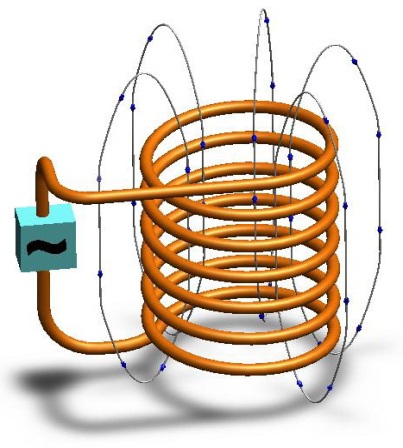
Если проводник скрутить в спираль и концы его присоединить к источнику переменного тока, получится катушка индуктивности (индуктор) с магнитным полем, изменяющимся при изменении силы тока. Поле замыкается вокруг катушки, и напряженность его зависит от силы тока и количества витков катушки.
Если поместить внутри катушки металлический или иной электропроводящий предмет, в теле предмета (детали) вследствие явления электромагнитной индукции образуются вихревые токи (токи Фуко), которые вследствие электрического сопротивления материала детали вызовут её нагрев. Эффект нагрева возрастает с ростом напряженности поля и зависит от свойств материала и расстояния катушки от поверхности детали, то есть от геометрии системы «индуктор-деталь».
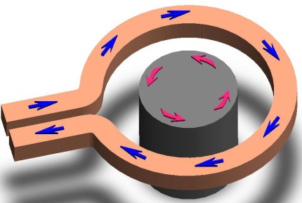
Наведенный ток будет создавать собственное, противоположное основному поле, что приводит к ослаблению поля в центре детали по мере удаления от поверхности внутрь нагреваемого предмета. По этой причине сила вихревых токов максимальна на поверхности предмета и понижается по направлению к центру. Это явление неравномерного распределения плотности переменного электрического тока по сечению проводника называется поверхностным эффектом (скин-эффектом).
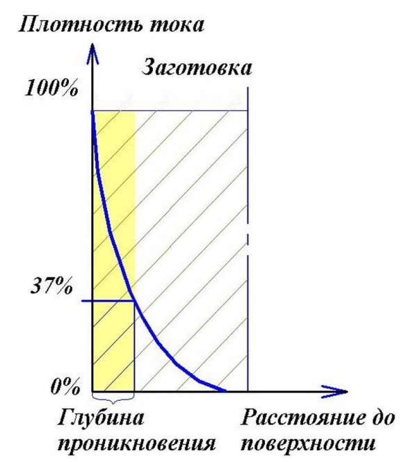
Расстояние от поверхности, на котором плотность наведённого тока убывает в e=2,718 раз (основание натурального логарифма), или, проще говоря, до уровня 37%, называется глубиной проникновения электромагнитного поля в материал. В слое этой глубины выделяется 86,5% энергии от вихревых токов.
С ростом частоты, электропроводности и магнитной проницаемости материала глубина проникновения уменьшается, с понижением частоты поля глубина проникновения увеличивается. Наложение вихревых токов во внутренних областях предмета вызывает понижение эффективности индуктора. По этой причине особенно важно выбирать частоту поля в соответствии с габаритами нагреваемого предмета.
Поверхностный эффект, так же, как и связанные с ним эффект близости и кольцевой (катушечный) эффект необходимо учитывать при выполнении работ по индукционному нагреву, чтобы избежать излишних потерь энергии и перерасхода дорогостоящих проводниковых материалов.
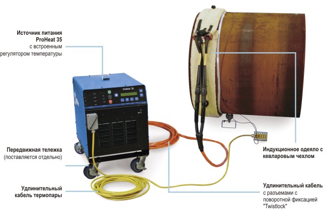
Система индукционного нагрева ProHeat35 Miller

Система индукционного нагрева с жидкостным охлаждением рассчитана на предварительный подогрев под сварку при температурах до 788 градусов С. Система, может использоваться в режиме ручного программирования, когда выходная мощность подается к детали в течение заданного времени, или в режиме автоматического программирования, когда выходная мощность регулируется в зависимости от температуры детали. Кабели с жидкостным охлаждением представляют собой универсальный инструмент для предварительного нагрева труб различных диаметров и также плоских деталей.
Технические характеристики
|
Наименование |
ProHeat 35 |
|
Процесс |
Индукционный нагрев |
|
Номинальная выходная мощность, кВт |
35 (ПВ=100%) |
|
Частота, кГц |
5-30 |
|
Напряжение первичное, В |
380 |
|
Напряжение вторичное, В |
460 |
|
Габаритные размеры, мм |
635х552х933 |
|
Масса, кг |
103 |
Состав системы индукционного нагрева:
с воздушным охлаждением:
с жидкостным охлаждением:
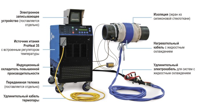
Типичные сферы применения
систем индукционного нагрева Miller ProHeat 35
- Магистральные трубопроводы
- Цеха для сварки труб (трубосварочные базы)
- Нефтехимия
- Судостроение
- Горнорудная промышленность
- Производство обсадных труб
- Горячая посадка
- Трубопрокатные заводы, металлургические предприятия
- Полевые условия, строительство магистральных и технологических трубопроводов
- ТЭК
- Машиностроительные заводы
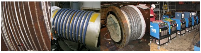
Основные особенности
Простота подключения питания сети через соединительную панель, без необходимости снятия панелей корпуса.
Наличие нескольких выходов с двумя изолированными разъемами для воздухоохлаждаемых рубашек или кабелей с жидкостным охлаждением.
Удобство перемещения при помощи подъёмной петли или опционной передвижной тележки, предназначенной для использования на стройках и при техническом обслуживании.
Встроенный регулятор температуры обеспечивает ручное или автоматическое программирование в рамках простого интерфейса оператора.
Функция распознавания незагруженного канала предотвращает включение системы, если разъём не закрыт (подключенным кабелем или защитной заглушкой).
Система идентификации кабеля распознаёт тип подключённого кабеля и определяет пределы мощности, чтобы защитить кабели и одеяла от перегрева.
Простота наладки благодаря использованию индукционных одеял для предварительного нагрева или гибких нагревательных кабелей с безопасными теплоизоляционными матами.
Высокая энергоэффективность системы (свыше 90%) позволяет передать обрабатываемой детали больше энергии, сокращая время нагрева и повышая отдачу мощности (потребление тока менее 60 А).
Защита от короткого замыкания обеспечивает автоматическое отключение системы. Сенсорный датчик выходной цепи сигнализирует аппарату об обнаружении неисправности.
Система обучения оператора предоставляет полезную информацию по оптимизации расположения витков кабеля на изделии для максимальной теплоотдачи.
Экономия на расходных материалах. Отсутствие топливных затрат и минимальные затраты на теплоизоляцию. Жаропрочные маты могут использоваться более 50 раз, что снижает затраты на их утилизацию и замену.
Однородное прогревание поддерживается по всей области нагрева благодаря индукции, нагревающей металл «изнутри». Поверхность детали не повреждается локализованной передачей тепла, даже если температура превышает заданные значения.
Скорость нагрева быстрее, чем при традиционных процессах, благодаря методу передачи тепла, который помогает сократить цикл нагрева.
Улучшаются условия труда при сварочных процессах: сварщики избавлены от необходимости работать с открытым пламенем, взрывоопасными газами и горячими элементами, как это обычно бывает при нагреве газовыми горелками и резистивном нагреве.
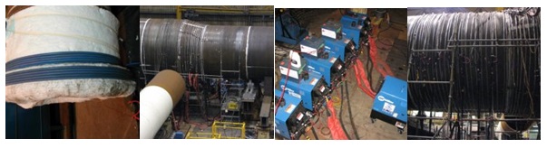
СПРАВОЧНАЯ ИНФОРМАЦИЯ
Термическая обработка сварных соединений
В термическую обработку сварных изделий входит термическая подготовка деталей перед сваркой, термическая обработка в процессе сварки и термическая обработка готового сварного изделия. Термическая подготовка деталей перед сваркой выполняется для улучшения свариваемости металла. Поэтому свариваемую сталь перед сваркой рекомендуется подвергать отжигу или высокому отпуску, режимы, которых зависят от состава стали.
Выбор теплового режима сварки зависит от свойств свариваемых металлов и сплавов, жесткости конструкции и состояния ее при сварке. При сварке черных металлов термический режим состоит в подогреве свариваемых деталей. Причем для стали, чем выше склонность ее к закатке и трещинам, тем выше должна быть температура подогрева.
Термическая обработка после сварки проводится для снятия напряжений, полученных в результате сварки и для улучшения механических свойств. При сварке применяют следующие виды термической обработки.
Отжиг для снятия внутренних напряжений. После сварки на изделие накладываются витки гибкого индуктора, и нагрев осуществляют постепенно. Для низко- и среднеуглеродистых сталей температура нагрева достигает 600—680°С. После нагрева, изделие выдерживают при этой температуре в течение 2,5 мин на 1 мм толщины металла, и охлаждают, не снимая укрывной материал.
Для полного отжига стальное изделие нагревают до температуры 820—930°С, выдерживают при этой температуре и затем медленно охлаждают. Время выдержки изделия при данной температуре такое же, как и при отжиге для снятия напряжений, но не менее 30 мин. Затем изделие охлаждают со скоростью 50-75°С в час, до температуры 300°С, после чего его охлаждают на воздухе. При полном отжиге устраняются внутренние напряжения, и улучшается структура металла. Металл становится мелкозернистым и более пластичным.
Нормализация — это термическая обработка, подобная отжигу, но с более быстрым охлаждением изделий, которое обычно проводят на воздухе. При нормализации сварное изделие нагревают до температуры 850—900°С, выдерживают при этой температуре и затем охлаждают на воздухе. В этом случае металл шва и околошовной зоны приобретает мелкозернистую структуру, повышается его прочность и твердость.
Отпуск применяется для сталей, склонных к закалке, для уменьшения внутренних напряжений и хрупкости. Изделие нагревают до температуры 400-700°С, выдерживают при этой температуре из расчета 2,5 мин на 1 мм толщины металла, медленно охлаждают до нормальной температуры. Поскольку изделия в этом случае нагреваются до температуры, лежащей ниже критической (723°С), структурных изменений в сварном шве и околошовной зоне не происходит.
Для каждой марки стали существуют свои режимы отпуска и скорости охлаждения, которые указываются в технических условиях на термообработку. и устраняются внутренние напряжения, и улучшается структура металла.
РД 153-34.1-003-01
Режимы термообработки стыковых сварных соединений элементов труб.
|
Свариваемая сталь |
Металл шва |
Толщина *1 элемента, мм |
Режим термической обработки*2 |
|
|
температура, °С |
длительность выдержки, ч, не менее*3 |
|||
|
Все виды дуговой сварки |
||||
|
10,20, 15Л, 20Л, 15ГС, 16ГС, 25Л, 20ГСЛ и их сочетания |
Углеродистый |
Свыше 36*4 до 60 Свыше 60 |
560-590 560-590 |
1 2 |
|
12МХ, 15ХМ, 20ХМЛ и их сочетания |
09МХ, 09Х1М |
Свыше 10 до 20 Свыше 20 до 45 Свыше 45 |
700-730 700-730 700-730 |
1 2 3 |
|
12Х1МФ |
09Х1М |
Свыше 10 до 20 Свыше 20 до 45 Свыше 45 |
710-740 710-740 710-740 |
1 2 3 |
|
12Х1МФ, 15Х1М1Ф, 20ХМФЛ, 15Х1М1ФЛ и их сочетания |
09Х1МФ |
Свыше 10*5 до 20 Свыше 20 до 60 Свыше 60 |
720-750 720-750 720-750 |
1*6 3 5 |
|
15Х1М1Ф-ЦЛ*7 |
09Х1МФ |
Свыше 20 |
735-765 |
5 |
|
10, 20, 20Л, 25Л, 15ГС, 16ГС, 20ГСЛ в сочетании с 12МХ и 15ХМ |
Э50А, 09Х1М, 09МХ |
Свыше 20 до 60 Свыше 60 |
690-720 690-720 |
2 3 |
|
10, 20, 20Л, 25Л, 15ГС, 16ГС, 20ГСЛ в сочетании с 12Х1МФ, 20ХМФЛ, 15Х1М1Ф, 15Х1М1ФЛ |
Э50А*8, 09Х1М, 09МХ, 09Х1МФ |
Свыше 10 до 20 Свыше 20 до 45 Свыше 45 |
700-730 700-730 700-730 |
1 2 3 |
|
12МХ, 15ХМ, 20ХМЛ в сочетании с 12Х1МФ |
09Х1М, 09МХ, 09Х1МФ |
Свыше 10 до 20 Свыше 20 до 45 Свыше 45 |
710-740 710-740 710-740 |
1 2 3 |
|
12МХ, 15ХМ, 20ХМЛ в сочетании с 20ХМФЛ, 15Х1М1Ф, 15Х1М1ФЛ |
09Х1М, 09МХ, 09Х1МФ |
Свыше 10 до 20 Свыше 20 до 60 Свыше 60 |
710-740 710-740 710-740 |
1 3 5 |
|
10Х9МФБ (ДИ 82-Ш) |
10Х9НМФ, 10Х9ГСНМФ |
4-6 |
750 |
0,5 |
|
12Х1МФ в сочетании с 10Х9МФБ (ДИ 82-Ш) |
09Х1МФ |
4-6 |
730 |
0,5 |
|
Газовая сварка |
||||
|
12МХ, 15ХМ 12Х1МФ |
09МХ, D9X1M 09Х1М, 09МХ, 09Х1МФ |
3-7 3-7 |
940±15 960±15 |
1,0-1,5 мин/мм толщины стенки 1,0-1,5 мин/мм толщины стенки |
*1 При соединении элементов одинаковой толщины — номинальная толщина этих элементов, при соединении элементов разной толщины (обработанных в соответствии с рис. 6.3 и 6.4) — фактическая толщина элемента непосредственно в месте сварки.
*2 Охлаждение до 300 °С после выдержки при отпуске должно обеспечиваться без снятия нагревательного устройства или под слоем теплоизоляции, далее — возможно на спокойном воздухе; при отрицательных температурах воздуха охлаждение после термообработки следует производить под слоем теплоизоляции до полного остывания сварного соединения.
*3 Может быть выше указанных значений не более чем на 1 ч. При вынужденных перерывах в процессе термообработки за длительность выдержки следует принимать суммарное время нахождения стыка при температуре обработки.
*4 В случае предварительного и сопутствующего подогрева стыка до температуры не ниже 100 °С при толщине стенки элемента 40 мм и менее термообработку сварного соединения можно не производить, кроме стыков, в которых хотя бы один из свариваемых элементов является литьем марки 25Л или 20ГСЛ.
*5 Стыки труб диаметром более 219 мм подлежат термообработке при толщине стенки 8 мм и более.
*6 Для стыков труб из стали 12Х1МФ с литьем 20ХМФЛ и 15Х1М1ФЛ, а также из стали 15Х1М1Ф с литьем 15Х1М1ФЛ при толщине стенки трубы 20 мм и менее, сваренных электродами типа Э-09Х1МФ, длительность выдержки должна составлять 1,5 ч.
*7 Скорость нагрева до температуры отпуска не более 200 °С/ч, при этом в интервале температур 600—700 °С скорость нагрева должна быть не менее 100 °С/ч.
*8 Термообработка сварных соединений, выполненных электродами типа Э50А, производится при толщине металла более 20 мм.
- Главная
-
Miller Electric
-
Сварочные системы
-
ProHeat 35
На этой странице вы найдёте полный список документов на Сварочные системы Miller Electric ProHeat 35.
Выберите необходимый PDF файл.
-

Сварочные системы
Miller Electric ProHeat 35 Инструкция по эксплуатацииТип файла
PDFРазмер
2.35 MbКол-во страниц
72Просмотров
2068Download / Read online

- 1
Другие Miller Electric Сварочные системы
-
Miller Electric 500 X Инструкция по эксплуатации
PDF файлов
1Просмотров
10130 -
Miller Electric 400P Инструкция по эксплуатации
PDF файлов
1Просмотров
10002 -
Miller Electric Big 40 C Инструкция по эксплуатации
PDF файлов
1Просмотров
9464 -
Miller Electric 225 Руководство по эксплуатации
PDF файлов
1Просмотров
8468 -
Miller Electric AEAD-200LE Техническая инструкция
PDF файлов
1Просмотров
8188 -
Miller Electric 301 G, DC Инструкция по эксплуатации
PDF файлов
1Просмотров
7626
Другие устройства Miller Electric
-
Сварочные аппараты
Miller Electric Millermatic 350 Руководство пользователяPDF файлов
2Просмотров
9375 -
Сварочные аппараты
Miller Electric IH Инструкция по эксплуатацииPDF файлов
1Просмотров
8061 -
Портативные генераторы
Miller Electric Big Blue 300 P Инструкция по эксплуатацииPDF файлов
1Просмотров
7863 -
Сварочные аппараты
Miller Electric 250 Инструкция по эксплуатацииPDF файлов
1Просмотров
7728 -
Сварочные аппараты
Miller Electric OM-1589 Инструкция по эксплуатацииPDF файлов
1Просмотров
6878 -
Портативные генераторы
Miller Electric Blue Star 6000 Инструкция по эксплуатацииPDF файлов
1Просмотров
6867
Вопросы
-
слабая батарея
Ноутбуки
Acer
1310
Alex 12.02.2016 17:26
Ранее вы смотрели
Производители
Bethesda
Charvel
Disney Interactive Studios
Eicon Networks
Exo Terra
GE Monogram
Hobie
Matrix Hairstyles
Sangean
SSD COMPANY LIMITED
Типы устройств
GPS-навигаторы
Пылесосы
Автомобильные зарядные устройства
Эквалайзеры
Продукция для грузовиков
Эпиляторы
Принтеры для этикеток
Цифровой медиа-ресивер
Сетевые аудиоплееры
Мойки высокого давления
Устройства
Craftsman 10″ Portable Table Saw
DCS CMOH30SS
Dimplex DS7425DLX
Dynex DX-40L130A11
Kenmore POWER MISER 6 153336162
Maytag W10249362A
Nokia N-3100
Stamina 50-0001
The Eltron Company P 7 2 0
freeuserguide.ru
About Us
Contacts
Disclamers
Privacy Policy
Эта страница полезна для вас? Поделитесь ссылкой: