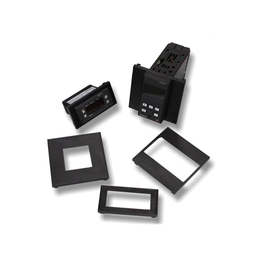
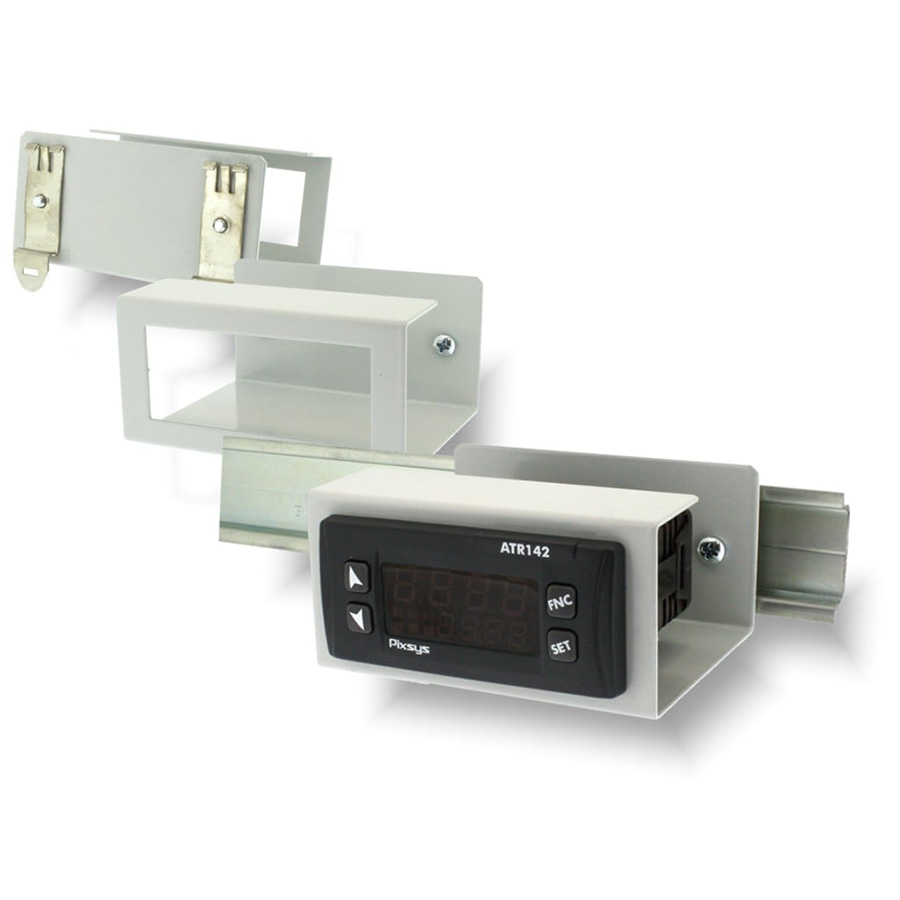
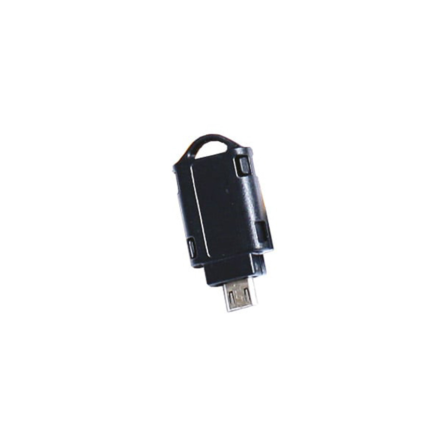
Этот регулятор я выбрал только потому что он на практике показал свою надёжность. Цена у него тоже приемлема, и в технических параметрах указано что он может храниться при температурае до -30 градусов. Это важно поскольку оборудование зимой стоит на улице.
Pixsys
ATR121 настройка
регулятора.
Кнопки:
SET
изменение
текущего задания OUT1
или
OUT2
FNC
Функциональная
кнопка доступа к параметрам и выхода
из режима параметров.
Δ
Кнопка
“На
верх”
изменение
задания или параметра в режиме параметров
∇ Кнопка
“Вниз”
изменение
задания или параметра в режиме параметров
Изменение
задания.
«1 уровень
»:
-
Если
нажать кнопки Δ
или ∇
то
регулятор сразу изменяет задание для
OUT
1. При
этом индикатор OUT
1
мигает.
-
Можно
нажать на кнопку SET.
Тогда
регулятор переходит к изменению OUT
1. Так
же мигает индикатор OUT
1. Если
нажать ещё раз SET
то
регулятор перейдёт на изменение задания
OUT
2. Будет
мигать индикатор OUT
2. -
После
окончания изменения задания регулятор
сам автоматически перейдёт в режим
индикации текущей температуры.
Изменение
параметров регулятора.
Нажать
кнопку
FNC на
5 сек.
На
дисплее появятся
000 и
первый с лева ноль будет мигать.
Кнопкой▲
изменить
значение на
1. Перейти
к следующей цифре можно нажав кнопку
SET. Весь
пароль:
123
Выход
из режима параметрирования — нажать
кнопку FNC.
|
Параметр |
Описание |
Значение |
|
c.ou |
Типы |
Не |
|
SEn. |
Выбор |
Pt1 |
|
dP. |
Десятичная |
|
|
Lo.S. |
Нижний |
0 |
|
Hi.S. |
Верхний |
120 |
|
cA.o |
Коррекция |
+ |
|
rEG. |
Тип работы. Нагрев или |
В |
|
HY.c |
Гистерезис. Возврат |
2.0 |
Остальные
параметры не меняются. Александр
Клапин
-
Page 1
ATR 121-141 Controller / Regolatore User manual / Manuale d’uso… -
Page 3: Table Of Contents
Table of contents 1 Safety guide lines …………….5 2 Model identification …………….6 3 Technical features …………….6 3.1 General features…………….. 6 4 Hardware features …………….7 4.1 Software features …………..8 5 Dimensions and installation …………8 6 Electrical wirings …………….. 9 6.1 Wiring diagram …………….
-
Page 4
Sommario 1 Norme di sicurezza …………….42 2 Identificazione del modello …………43 3 Dati tecnici ………………43 3.1 Caratteristiche generali …………43 4 Caratteristiche hardware …………..44 4.1 Caratteristiche software …………45 5 Dimensione e installazione …………46 6 Collegamenti elettrici……………46 6.1 Schema di collegamento …………47 7 Funzione dei visualizzatori e tasti ……….51 7.1 Indicatori numerici (display) ……….51 7.2 Significato delle spie di stato (led) ……..51… -
Page 5: Safety Guide Lines
, while LATCH ON function speeds up the device calibration when linear potentiometers are used. As on the latest Pixsys instrumentation, the configuration is further simplified by the Memory cards which are provided with internal battery and therefore do not require cabling to power the controller.
-
Page 6: Model Identification
Model identification ATR121-141 AD 12..24Vac ±10% 50/60Hz 12..35Vdc ATR121-141 A 24 Vac ±10% 50/60 Hz (galvanical isolation 2500V) ATR121-141 B 230 Vac ±10% 50/60 Hz (galvanical isolation 2500V) ATR121-141 C 115 Vac ±10% 50/60 Hz (galvanical isolation 2500V) ATR121-141 ADT 12..35Vdc + RS485 Relay Q2 not available, alarm function available on SSR output.
-
Page 7: Hardware Features
Hardware features Acuracy: Ris. 16bit. For Thermocouple: AN1. Configurable via @25°C ±0,5% (full scale) software. or ± 1 digit, automatic Thermocouple type: compensation of cold K, S, R, J. junction from 0°C to 50°C. Thermoresistance: For linear input: Analogue PT100, PT500, PT1000, 0/4..20mA: 30000 points, inputs Ni100, PTC1K, NTC10K…
-
Page 8: Software Features
4.1 Software features Regulation ON-OFF with hysteresis. algorithms P, PI, PID, PD with proportional time Proportional 0..999°C or °F band Integral time 0..999s (0 excludes integral function) Derivative time 0..999s (0 excludes derivative function) Manual or automatic Tuning, Controller configurable alarm, protection of functions command and alarm setpoints, heating/ cooling PID function.
-
Page 9: Electrical Wirings
Electrical wirings Although this controller has been designed to resist electromagnetic interferences in industrial environments, please observe following safety guidelines: • Separate control line from power wires. • Avoid proximity of remote control switches, electroma- gnetic contactors, powerful engines and in all instances use specific filters.
-
Page 10
6.1.b Models: ATR121-A-B-C and ATR141-A-B-C ATR121/141 — A: 24Vac ±10% 50/60Hz Class 2 source Vac supply ATR121/141 — B: 230Vac ±10% 50/60Hz ATR121/141 — C: 115Vac ±10% 50/60Hz Use copper conductors only 6.1.c AN1 Analogue Input For thermocouples K, S, R, J. •… -
Page 11
For thermoresistances NTC, PTC, Shield/Schermo PT500, PT1000 e potentiometers • When shielded cable is used, it should be grounded at one side only to avoid ground loop currents For linear signals V/mA Shield/Schermo • Comply with polarity • When shielded cable is used, it should be grounded at one side only 6.1.d Examples of connection for linear input… -
Page 12
For signals 0/4…20mA with two-wire sensor • Comply with polarity 4…20mA C = Sensor output A = Sensor power supply Versions AD / ADT: 12..24Vdc / 30mA PRESSURE TRANSMITTER SENSORE DI PRESSIONE Versions A-B-C: 8Vdc / 20 mA 6.1.e Serial input RS485 Modbus RTU communication Do not use LT (line termination) resistors… -
Page 13: Display And Keys Functions
6.1.g SSR output SSR command output 12V/30mA Versions AD / ADT: 12..24Vdc / 30mA Versions A-B-C: 8Vdc / 20 mA Display and keys functions Numeric indicators (Display) 1 1234 Normally displays the process. Meaning of status lights (Led) ON when command output is active. When 2 OUT1 it flashes, display shows the command output setpoint (which can be modified by arrow keys).
-
Page 14: Keys
Keys • Allows to decrease main setpoint. • During configuration it allows to scroll through parameters and to modify them togheter with SET 5 “ m ” • If pressed after SET, it allows to decrease the setpoints (command with OUT1 flashing/ alarm with OUT2 flashing).
-
Page 15: Tuning
Increase or decrease Display shows the the alarm setpoint Press twice alarm setpoint and value. After 4s OUT2 flashes. display shows the process. Tuning Tuning procedure allows to calculate PID parameters to obtain a good regulation. It means a stable control of temperature/ process on setpoint without fluctuations and fast response to deviations from setpoint caused by external noises.
-
Page 16: Automatic Tuning
Pressing “ n ” display shows mLd . Confi rming with FNC, the controller loads the new data and starts again. Pressing “ m ” display shows mno and the controller starts keeping values unchanged. PIXSYS Memory Card (optional) Memory Card (optional) Cod. 2100.30.005 with battery/con batteria Cod.
-
Page 17: Latch On Function
• With the controller not connected to power supply: The memory card is equipped with an internal battery with an autonomy of about 1000 operations (button battery 2032, replaceable). Insert the memory card and press the programming button . When writing the parameters, the led turns red and on completing the procedure it turns green.
-
Page 18
For the calibration procedure refer to the following table: Press Display Exit parameters Place the sensor on confi guration. minimum operating 1 FNC Device visualizes value (associated with alternately process Lo. n ) and Lat Place the sensor on Set the value on maximum operating 2 “… -
Page 19: Dual Action Heating-Cooling
9.6 Dual action Heating-Cooling The ATR121/141 is suitable also for systems requiring a combined heating-cooling action. Command output must be configured as Heating PID (par.11 reG. = Hea | Heat and par. 15 p.b. greater than 0), and one of the alarm must be configured as cooling action (par.
-
Page 20
x = COOL x = COOL x = COOL < 0 < 0 < 0 (HEAT) (HEAT) (HEAT) ACTIVE COMMAND OUTPUT (HEAT) ACTIVE COMMAND OUTPUT (HEAT) ACTIVE COMMAND OUTPUT (HEAT) ACTIVE ALARM OUTPUT (COOL) ACTIVE… -
Page 21: Dead Band Function
Cooling fluid type co.f | coo.f P.b.m t.c.2 1.00 1.25 Water 2.50 Dead band function The dead band function (enabled selecting F.b.M on par. 28 FNc | Func. ) creates a band within which the relays are both open or closed. In heating functioning (par.
-
Page 22: Serial Communication
Serial communication ATR121/141 is equipped with RS485, it can receive and broadcast data via serial communication using MODBUS RTU protocol. The device can be configured only as Slave. This function enables the control of multiple devices connected to a supervisory system. The RS485 line must be free of LT termination resistances to avoid malfunctions.
-
Page 23
WORD READING (max 20 words) (0x03, 0x04) Supported SINGLE WORD WRITING (0x06) functions MULTIPLE WORDS WRITING (max 20 words) (0x10) list below includes available addresses: RO = Read Only R/W = Read/Write WO = Write Only Modbus Read Reset Description Address Only value… -
Page 24
Error flags Bit0 = Eeprom writing error Bit1 = Eeprom reading error 1008 Bit2 = Cold junction error Bit3 = Process error (sensor) Bit4 = Generic error Bit5 = Missing calibration data Start/Stop 1009 0 = controller in STOP R/W 0 1 = controller in START 1010 OFF LINE* time (milliseconds) -
Page 25: Configuration
2024 Par. 24 de.a — deL.a R/W EEPR 2025 Par. 25 p.se. — p.se. R/W EEPR 2026 Par. 26 fiL. — fiLt. R/W EEPR 2027 Par. 27 tun — tune R/W EEPR 2028 Par. 28 FNc — Func. R/W EEPR 2029 Par.
-
Page 26: Modify Configuration Parameters
12.2 Modify configuration parameters Press Display Display shows 000 | FNC for 0000 with the 1st digit flashing Change the flashing Enter the configuration “ n ” or digit and move to the password “ 123 ” (“ 1234 ” “…
-
Page 27: Configuration Parameters
Configuration parameters ATR121 | ATR141 01 c.ou | c.out Command output Selects command output type. o1.2 | o1.o2 > Default (factory defaults) o1.S | o1.o2 SSr | SSr o2. 1 | o2.o1. Ser | Seru. (Alarm not available with this selection) Command Alarm o1.2 | o1.o2…
-
Page 28
ptc | ptc Ptc 1KΩ -50 °C..150 °C pts | pts Pt500 -100 °C..600 °C | pk1k Pt1000 -100 °C..600 °C 0. 1 0 | 0. 1 0 0..10V 0.20 | 0.20 0..20mA 4.20 | 4.20 4..20mA | pot1 Potent. ≤ 6KΩ F.S. po2 | pot2 Potent. -
Page 29
07 Hi.n Upper Linear Input Range AN1 upper limit only for linear signals. Example: with input 4…20 mA this parameter takes value associated to 20 mA -199..999 | -999..9999 Value in digit (default 999) 08 Lat | Latc Latch On function Automatic setting of limits for linear potentiometers and linear inputs. -
Page 30
11 ReG. Regulation type | HEAT Heating (N.A.) (Default) coo | cooL Cooling (N.C.) | m.r. Absolute alarm with manual reset m.r. m.r.m | m.r.m. Absolute alarm with manual reset and relay status stored in case of power failure. H.o.o | H.o.o Heating with PID always to 0 if the process is over the setpoint. -
Page 31
16 t.i. Integral time Process inertia in seconds 0..999 | 0..9999 s (0 = integral disabled) (default 0) 17 t.d. Derivative time Normally ¼ of integral time 0..999 | 0..9999 s (0 = derivative disabled) (default 0) 18 t.c. Cycle time Cycle time (for PID on remote control switch 10/15 sec, for PID on SSR 1s) or servo time (value declared by servo-motor manufacturer). -
Page 32
20 c.r.a Alarm state output Output contact and intervention type Normally open, active at start (default) n.o.s Normally closed, active at start n.c.s Normally open, active on reaching alarm n.o.r Normally closed, active on reaching alarm n.c.r 21 s.c.a Alarm state error State of contact for alarm output in case of error (eg. -
Page 33
25 p.se. Setpoint protection Allows or not to modify the setpoint by keyboard. fre | free Both set can be modified (default) pr.s | pro.s OUT1 command setpoint protection pr.a | pro.a OUT2 alarm setpoint protection aLL | aLL Both set protection 26 fiL | FiLt. -
Page 34
keys operation. s.s.v | s.s.vi Setpoint visualizer: setpoint is always displayed. To visualize the process press FNC. 29 Gra | Grad. Degree selection Select degree type Centigrade (default) c Fahrenheit f 30 bd.r | bd.rt. Baud rate Selects baud rate for serial communication mb. -
Page 35
34 p.b.m Proportional band multiplayer 1.00..5.00 Proportional band for cooling action is given by par. p.b. multiplied for this value (par. 12) (default 1.00) 35 ou.d | ou.d.b. Overlap / dead band Dead band combination for heating/cooling action in (par. 12) heating / cooling PID.mode -20.0..50.0% of par. -
Page 36: Alarm Intervention Modes
Alarm intervention modes 14.a Absolute alarm or threshold alarm ( A. A AL.A. selection) Absolute alarm with Alarm Spv controller in heating Hysteresis parameter functioning (par. 11 reG. > 0 come Hea | Heat ) and hysteresis (par. 23 HY.a | Time Hys.a ) in absolute value.
-
Page 37
14.b Absolute alarm or threshold alarm referring to command setpoint ( selection) A.A.S AL.A.S. Absolute alarm refers to the command set, with the controller in heating Comand Spv functioning (par. 11 reG. Hysteresis come Hea | Heat ) and parameter … -
Page 38
14.d Upper deviation alarm ( selection) a.d.s AL.D.S. Upper deviation alarm Alarm Spv Alarm Spv value of alarm Hysteresis parameter > 0 setpoint greater than “0”. Comand Spv Comand Spv N.B.: hysteresis (par. 23 HY.a | Hys.a ) can not be Time lower than 0. -
Page 39: Table Of Anomaly Signals
Hysteresis parameter Lower deviation alarm > 0 Alarm Spv Alarm Spv Alarm Spv value of alarm setpoint less than “0”. Comand Spv Comand Spv Comand Spv Comand Spv Comand Spv N.B.: hysteresis (par. 23 HY.a | Hys.a ) can not be Time lower than 0.
-
Page 40
Table of configuration parameters Command output c.ou c.out Sensor Decimal point d.p. Lower Limit Setpoint Lo.s Upper Limit Setpoint Hi.s. Lower Linear Input Lo. N Upper Linear Input Hi.n Latch On function Latc Offset calibration cA.o caL.o. Gain calibration cA.G cAL.G Regulation type ReG. -
Page 41
Cooling fluid co.f coo.f. Proportional band multiplayer p.b.m Overlap / dead band ou.d ou.d.b. Cooling cycle time t.c.2 Visualization filter FL.u User manual — ATR121/141 -… -
Page 42: Norme Di Sicurezza
Introduzione Grazie per aver scelto un regolatore Pixsys. Le versioni con display a tre e quattro digits permettono di impiegare lo strumento in una vasta gamma di applicazioni, ad esempio con sensori di temperatura, umidità, pressione, livello o potenziometri lineari. Le soluzioni di uscita prevedono sia il relè…
-
Page 43: Identificazione Del Modello
Identificazione del modello ATR121-141 AD 12..24Vac ±10% 50/60Hz 12..35Vdc ATR121-141 A 24 Vac ±10% 50/60 Hz (isolamento galvanico 2500V) ATR121-141 B 230 Vac ±10% 50/60 Hz (isolamento galvanico 2500V) ATR121-141 C 115 Vac ±10% 50/60 Hz (isolamento galvanico 2500V) ATR121-141 ADT 12..35Vdc. Versione dotata di seriale RS485 Modbus: relè…
-
Page 44: Caratteristiche Hardware
Caratteristiche hardware Precisione: Ris. 16bit. Per termocoppie: @25°C AN1 Configurabile via ±0,5% F.S. oppure ±1 software digit, compensazione Termocoppie tipo: automatica del giunto K, S, R, J freddo 0..50°C. Termoresistenze: Per ingressi lineari: Ingressi PT100, PT500, PT1000, 0/4..20mA: 30000 punti, analogici Ni100, PTC1K, NTC10K 0..10V: 40000 punti.
-
Page 45: Caratteristiche Software
Mod. ATR121/141 A-B-C • 8Vdc/20mA Mod. ATR121/141 AD — ADT • 15Vdc/30mA (se alimentato a 12Vac) 1 SSR configurabile Uscita • 30Vdc/30mA (se come uscita comando e alimentato a 24Vac) allarme. • Se alimentato in continua, la tensione d’uscita è uguale a quella di alimentazione con 30mA max.
-
Page 46: Dimensione E Installazione
Dimensione e installazione Memory Card (optional) with battery Cod. 2100.30.005 Cod. 2100.30.003 42mm insert memory card inserimento memory card Collegamenti elettrici Benché questo regolatore sia stato progettato per resistere ai più gravosi disturbi presenti in ambienti industriali è buona norma seguire la seguenti precauzioni: •…
-
Page 47: Schema Di Collegamento
6.1 Schema di collegamento 6.1.a Modelli: ATR121-AD/ADT e ATR141-AD/ADT ATR121/141 — AD: class 2 source 12..24Vac ±10% 50Hz/60Hz 12..35Vdc (rispettare la polarità) NB: per versione T con seriale alimentare solo a 12..35Vdc. Usare solo fili di rame. 6.1.b Modelli: ATR121-A-B-C e ATR141-A-B-C ATR121/141 — A: 24Vac ±10% 50/60Hz class 2 source Vac supply…
-
Page 48
6.1.c AN1 Ingresso analogico Per termocoppie K, S, R, J. • Rispettare la polarità • Per eventuali prolunghe utilizzare cavo compensato e morsetti adatti alla termocoppia utilizzata (compensati) • Quando si usa cavo schermato lo Shield/Schermo schermo deve essere collegato a terra ad una sola estremità… -
Page 49
Per segnali normalizzati in corrente e tensione Shield/Schermo • Rispettare la polarità • Quando si usa cavo schermato lo schermo deve essere collegato a terra ad una sola estremità 6.1.d Esempi di collegamento per ingressi normalizzati Per segnali normalizzati in tensione 0..10V 0…10V •… -
Page 50
Per segnali normalizzati in corrente 0/4..20mA con sensore a due fili • Rispettare le polarità 4…20mA C = Uscita sensore A = Alimentazione sensore PRESSURE TRANSMITTER Ver. AD / ADT: portata 12..24Vdc / 30mA SENSORE DI PRESSIONE Ver. A-B-C: portata 8Vdc / 20 mA 6.1.e Ingresso seriale RS485, protocollo MODBUS-RTU… -
Page 51: Funzione Dei Visualizzatori E Tasti
6.1.g Uscita SSR Uscita comando SSR portata 12V/30mA Ver. AD / ADT: portata 12..24Vdc / 30mA. Vers. A-B-C: portata 8Vdc / 20 mA Funzione dei visualizzatori e tasti Indicatori numerici (display) Normalmente visualizza il processo. 1234 Significato delle spie di stato (led) Si accende quando l’uscita comando è…
-
Page 52: Tasti
Tasti • Decrementa il setpoint principale. • In fase di configurazione consente di scorrere i parametri e insieme a SET li modifica. “ m ” • Premuto dopo SET, decrementa i setpoint (di comando con OUT1 lampeggiante, di allarme con OUT2 lampeggiante). •…
-
Page 53: Funzioni Del Regolatore
Funzioni del regolatore 8.1 Modifica valore setpoint principale e di allarme Il valore dei setpoint può essere modificato da tastiera come segue: Premere Effetto Eseguire Incrementare o diminuire il valore Il display visualizza il del setpoint “ n ” o “ m ” setpoint di comando principale.
-
Page 54: Auto-Tune
per rimuovere segnalazioni di errore fisse, corrisponde all’inerzia del sistema in tempo). • Tempo derivativo (determina l’intensità della reazione del regolatore alla variazione del valore misurato, normalmente ¼ del tempo integrale). Durante il calcolo dell’autotune non è possibile cambiare il setpoint.
-
Page 55: Memory Card (Opzionale)
. Confermando con FNC, il regolatore carica i nuovi m-Ld valori e si avvia. Premendo, invece, “ m ” il display visualizza e il regolatore si avvia mantenendo invariati i valori. m-no PIXSYS Memory Card (optional) Memory Card (optional) Cod. 2100.30.005 with battery/con batteria Cod.
-
Page 56: Funzione Latch On
Aggiornamento memory card. Per salvare i parametri dal regolatore alla memory card, inserirla a strumento acceso. Entrare in configurazione e variare almeno un parametro. Uscendo dalla configurazione il salvataggio dei parametri è automatico e avviene sia all’interno dello strumento che nella memory card.
-
Page 57
Premere Eff etto Eseguire Esce dalla confi gurazio- ne parametri. Posizionare il sensore Lo strumento visualizza sul valore minimo 1 FNC alternativamente il di funzionamento processo e la scritta (associato a Lo. n Posizionare il sensore Fissa il valore sul sul valore massimo 2 “… -
Page 58: Funzionamento In Doppia Azione (Caldo-Freddo)
9.6 Funzionamento in doppia azione (Caldo-Freddo) L’ATR121/141 è adatto alla regolazione anche su impianti che prevedano un’azione combinata caldo-freddo. L’uscita di comando deve essere configurata in PID caldo (par.11 e par. 15 maggiore di 0), e reG. Heat p.b. l’allarme deve essere configurato come azione freddo (par. 19 .
-
Page 59
morta ( ≤ 0), viceversa si potrà configurare ou.d ou.d.b. una sovrapposizione ( > 0): ou.d ou.d.b. x = COOL x = COOL x = COOL < 0 < 0 < 0 … -
Page 60: Funzione Banda Morta
Il par. pre-seleziona il moltiplicatore di banda co.f coo.f proporzionale ed il tempo di ciclo del PID freddo P.b.m t.c.2 in base al tipo di fluido refrigerante: Fluido refrigerante co.f | coo.f P.b.m t.c.2 Aria 1.00 olio 1.25 Acqua 2.50 Funzione banda morta La funzione banda morta (abilitata impostando nel par.
-
Page 61: Comunicazione Seriale
Comunicazione seriale L’ATR121/141 con RS485 è in grado di ricevere e trasmettere dati via seriale tramite protocollo MODBUS RTU. Il dispositivo può essere configurato solo come Slave. Questa funzione permette il controllo di più unità ATR121/141 collegandole ad un sistema di supervisione.
-
Page 62
Si riporta di seguito l’elenco di tutti gli indirizzi disponibili, dove: RO = Read Only R/W = Read/Write WO = Write Only Modbus Read Reset Descrizione Address Only value Tipo dispositivo 101/102 Versione software Riservato Riservato Riservato Address Slave EEPR Riservato Caricamento valori di default (scrivere R/W 0… -
Page 63
Start/Stop 1009 0 = regolatore in STOP R/W 0 1 = regolatore in START 1010 Tempo OFF LINE* (millisecondi) R/W 0 2001 Par. 1 R/W EEPR c.ou c.out 2002 Par. 2 R/W EEPR sen. 2003 Par. 3 R/W EEPR d.p. 2004 Par. -
Page 64: Configurazione
2032 Par. 32 R/W EEPR de.s dL.sr. 2033 Par. 33 R/W EEPR co.f coo.f. 2034 Par. 34 R/W EEPR p.b.m p.b.m. 2035 Par. 35 R/W EEPR ou.d ou.db. 2036 Par. 36 R/W EEPR t.c.2 t.c. 2 2037 Par. 37 R/W EEPR fL.u fLt.u * Se vale 0 il controllo è…
-
Page 65: Modifica Parametri Di Configurazione
12.2 Modifica parametri di configurazione La configurazione dello strumento è prevista sotto password in quanto di responsabilità del gestore dell’ impianto. Tale password ha la funzione di preservare i parametri di con- figurazioni da operazioni indesiderate da parte dell’operatore e non è modificabile. Premere Effetto Eseguire…
-
Page 66: Parametri Di Configurazione
Parametri di configurazione ATR121 | ATR141 Command output c.ou c.out selezione tipo uscita di comando. > Default (Parametro di fabbrica) o1.2 o1.o2 o1.S o1.o2 o2. 1 o2.o1. (allarme non disponibile con questa Seru. selezione) Comando Allarme o1.2 o1.o2 o1.S o1.o2 o2.
-
Page 67
Ni100 -60 °C .. 180 °C NTC 10KΩ -40 °C .. 125 °C PTC 1KΩ -50 °C .. 150 °C PT500 -100 °C .. 600 °C PT1000 -100 °C .. 600 °C pk 1k 0..10V 0. 1 0 0. 1 0 0..20mA 0.20 0.20… -
Page 68
Lower Linear Input Lo. N Limite inferiore range AN1 solo normalizzati Esempio: con ingresso 4..20mA questo parametro assume il valore associato a 4mA -199 .. 999 | -999 .. 9999 Valore in digit (default 0) Upper Linear Input Hi.n Limite superiore range AN1 solo normalizzati Esempio: con ingresso 4..20mA questo parametro assume il valore associato a 20mA -199 .. -
Page 69
Regulation type ReG. Caldo (N.A.) (Default) HEAT Freddo (N.C.) cooL Allarme assoluto con riarmo manuale m.r. m.r. Allarme assoluto con riarmo manuale e m.r.m m.r.m. memoria stato relè in caso di spegnimento Caldo con PID sempre a 0 se il processo è H.o.o H.o.o sopra il set. -
Page 70
Integral time t. i . Tempo integrale. Inerzia del processo in secondi 0 .. 999 | 0 .. 9999 s (0 integrale disabilitato) (default 0) Derivative time t.d. Tempo derivativo. Normalmente ¼ del tempo integrale. 0..999 | 0..9999 s (0 derivativo disabilitato) (default 0) Cicle time t.c. -
Page 71
Alarm state output c.r.a Contatto uscita allarme e tipo intervento Normalmente aperto, operativo dall’accen- n.o.s sione (default) Normalmente chiuso, oper. dall’accensione n.c.s Normalmente aperto, operativo al raggiun- n.o.r gimento dell’allarme Normalmente chiuso, operativo al raggiun- n.c.r gimento dell’allarme Alarm state error s.c.a Stato del contatto per l’uscita di allarme in caso di errore (es. -
Page 72
Alarm delay de.a deL.a Ritardo allarme -180 .. 180 s Negativo: ritardo in fase di uscita dall’allarme. Positivo: ritardo in fase di entrata dell’allarme (default 0) Setpoint protection p.se. Consente o inibisce la modifica dei setpoint da tastiera Entrambi i set modificabili (default) free Protezione setpoint di comando OUT1 pr.s… -
Page 73
Operating / visualization mode func. Selezione funzionamento e opzioni di visualizzazione Doppio setpoint (default) d.se d.set Singolo setpoint s.se s.set Solo visualizzatore (par. 10)) Funzione banda morta f.b.m f.b.m. Funzione nascondi processo e setpoint main Demotica 1: spegne il display e i led dopo 1.do 1.dom. -
Page 74
Serial delay de.s dL.sr. Seleziona il ritardo di risposta seriale 0 .. 100 ms (default 20) Cooling fluid co.f coo.f. (par. Tipo di fluido refrigerante in modalità PID Caldo/Freddo 9.6) Aria (default) Olio Acqua Proportional band multiplayer p.b.m (par. 12) Moltiplicatore di banda proporzionale 1.00..5.00 La banda proporzionale per l’azione Freddo… -
Page 75: Modi D’intervento Allarme
Visualization fi lter FL.u Filtro in visualizzazione. Rallenta l’aggiornamento del valore di processo visualizzato sul display per facilitarne la lettura. Filtro disabilitato (massima velocità di aggiornamento display) (default) Filtro del primo ordine (cost. di tempo 1s). on.f Media su 2 campionamenti s.
-
Page 76
14.b Allarme assoluto o allarme di soglia riferito al setpoint di comando (selezione A.A.S AL.A.S. Allarme assoluto riferito al set di comando, Comand Spv con regolatore in Hysteresis funzionamento caldo parameter > 0 (par. 11 come reG. ) e isteresi (par. Heat Alarm Spv ) in… -
Page 77
14.d Allarme deviazione superiore (sel. a.d.s AL.D.S. Allarme di deviazione Alarm Spv Alarm Spv superiore con valore Hysteresis di setpoint allarme parameter > 0 maggiore di “0”. Comand Spv Comand Spv N.B.: l’isteresi (par. 23 HY.a Time ) non può essere Hys.a Alarm minore di 0. -
Page 78: Tabella Segnalazioni Anomalie
Tabella segnalazioni anomalie In caso di mal funzionamento dell’impianto il regolatore porta lo stato delle uscite come impostato nei par. 12 s.c.c. e segnala il tipo di anomalia riscontrata. s.c.a Es: il regolatore segnalerà la rottura di un’eventuale termocoppia collegata visualizzando (lampeggiante).
-
Page 79
3D dell’involucro? Scaricali dall’area documenta- zione. Are you a mechanical designer looking for the 3D model files of the enclosure? Download them from Documentation Area. www.pixsys.net/prodotti/regolatori-visualizzatori/atr121- 19-documentazione Manuale d’uso — ATR121/141 -… -
Page 80
Note / Aggiornamenti 80 — ATR121/141 — Manuale d’uso… -
Page 81
Tabella delle configurazioni dei parametri Command output c.ou c.out Sensor Decimal point d.p. Lower Limit Setpoint Lo.s Upper Limit Setpoint Hi.s. Lower Linear Input Lo. N Upper Linear Input Hi.n Latch On function Latc Offset calibration cA.o caL.o. Gain calibration cA.G cAL.G Regulation type… -
Page 82
Cooling fluid co.f coo.f. Proportional band multiplayer p.b.m Overlap / dead band ou.d ou.d.b. Cooling cycle time t.c.2 Visualization filter FL.u 82 — ATR121/141 — Manuale d’uso… -
Page 84
Prima di utilizzare il dispositivo leggere con attenzione le informazioni di sicurezza e settaggio contenute in questo manuale. PIXSYS s.r.l. www.pixsys.net sales@pixsys.net — support@pixsys.net online assistance: http://forum.pixsys.net ATR121 ATR141 2300.10.056-RevF Software Rev. 3.05 110116…
Основные характеристики
Входы:
1 вход, настраиваемый для термопар J, K, R или S; Pt100; ni100; Pt500; Pt1000; PTC; NTC; от 0/4 до 20 мА; от 0 до 10 В пост. тока; потенциометры <= 6кОм или <= 150кОм
Выходы:
Реле управления 8 А; Сигнальное реле 5 А; SSR Управление/Сигнализация; Логика открытия/закрытия (пропорционально времени), RS485 Modbus RTU Slave (модели -ADT)
Управляющие действия:
ВКЛ/ВЫКЛ; автонастройка ПИД-регулятора; ПИД-регулирование нагрева/охлаждения
Конфигурация:
С помощью кнопок управления, карты памяти или программного обеспечения LABSOFTVIEW. Параметры защищены паролем
Дисплей:
3-разрядный красный светодиод плюс десятичная точка; зеленые светодиоды состояния
Точность:
0,5% ± 1 цифра для TC/RTD; 0,2% ± 1 цифра для мА/В
Время выборки:
66 мс (выбираемый программный фильтр на входе и дисплее)
Напряжение питания:
230 В перем. тока, 115 В перем. тока или 12–24 В перем./пост. тока (в зависимости от модели)
Потребляемая мощность:
2 Вт
Рабочая температура:
от 0°С до 40°С
Рабочая влажность:
от 35% до 95% относительной влажности
Герметизация:
Передняя панель IP54 (IP65 с прокладкой), корпус IP30, клеммные колодки IP20
Размеры:
32(В) x 74(Ш) x 58(Г) мм
Электрическое подключение
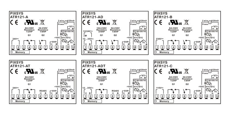
Размеры (мм)
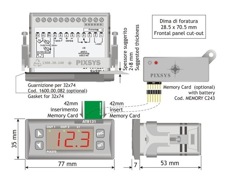
Для ATR121 доступны следующие аксессуары:
- Карта памяти для быстрой настройки многих контроллеров
- Программное обеспечение LABSOFTVIEW для настройки
- Уплотнительная прокладка панели
Варианты заказа
ATR121-AD — 1 конфигурируемый вход, 2 релейных 8 A + 1 SSR выходы, напряжение питания 12–24 В перем./пост. тока (неизолированные)
ATR121-B — 1 конфигурируемый вход, 2 релейных 8 A + 1 SSR 12 В пост. тока выходы, напряжение питания 230 В перем. тока (изолированные)
ATR121-ADT — 1 конфигурируемый вход, 1 релейный 8 A + 1 SSR 12 В пост. тока + RS485 Modbus RTU Slave выходы, напряжение питания 12–24 В перем./пост. тока (неизолированные)
Купить Регулятор температуры ATR121-B производителя PIXSYS можно оптом и в розницу с доставкой по всей России, Казахстану и Республике Беларусь, а так же в другие страны Таможенного союза (Армения, Киргизия и др.).
Для того, чтобы купить данный товар по базовой цене в розницу, положите его в корзину и оформите заказ следуя детальной инструкции. Обращаем Ваше внимание, что в зависимости от увеличения объёма продукции перерасчёт розничной цены будет произведен автоматически. Оптовая цена на модуль регулятор ATR121 выставляется исключительно после отправки коммерческого запроса на e-mail: [email protected] или [email protected].
- Более подробная информация находится в разделе Оплата.
Мы работаем со всеми крупными транспортными компаниями и гарантируем оперативность и надежность каждой поставки независимо от региона присутствия заказчика. так же поставляются с различных складов Европы, Китая и США. Возможные варианты поставки запрашивайте у специалистов компании SUPPLY24.ONLINE.
- Более подробная информация находится в разделе Доставка.
Гарантия предоставляется непосредственно заводом-изготовителем PIXSYS . Гарантийный срок на ATR121-B соответствует гарантии официального производителя. Гарантийный ремонт или замена оборудования осуществляется исключительно после проведения экспертизы и установления факта гарантийного случая.
- Более подробная информация находится в разделах Гарантия и Условия Гарантийных Обязательств.
практически всех известных мировых брендов представлены нашей компанией. В случае если интересующий Вас товар не был найден на нашем сайте, обратитесь в службу технической поддержки или обслуживающему Вас менеджеру и наши инженеры подберут аналоги для Вашего оборудования. Таким образом, возможно снизить затраты до 20% на обслуживание оборудования и оптимизировать Ваши расходы. Компания SUPPLY24.ONLINE берёт на себя полную ответственность за правильность подбора аналога. Наша компания предлагает только разумный подход, если по ряду критериев запрашиваемый товар не подразумевает замену на аналог, мы не предлагаем замену.
Стратегическая цель нашей компании помочь Вам подобрать оборудование и товар с оптимальными характеристиками, и разобраться в огромном количестве товарных позиций и предложений.
Внимание!
- Характеристики,внешний вид и комплектация товара могут изменяться производителем без уведомления.
- Изображение продукции дано в качестве иллюстрации для ознакомления и может быть изменено без уведомления.
- Точную спецификацию смотрите во вкладке «Характеристики» .
- На модуль регулятор распространяется официальная гарантия от производителя!
- При необходимости установки программного обеспечения и использования аксессуаров сторонних производителей, просьба проверить их совместимость с устройством, детально изучив документацию на сайте производителя PIXSYS
- Запрещается нарушение заводских настроек и регулировок без привлечения специалистов сертифицированных сервисных центров.
Вид используемого дисплея
одновременно можно использовать один вход управления и один сигнальный
Размер монтажного отверстия
Электрические параметры выхода 1
Электрические параметры выхода 2
Диапазон контролируемой величины
Электрические параметры выхода 3
ДОСТАВКА ПО РОССИИ
Доставка осуществляется в течении 2-3 дней с момента зачисления средств на р/с компании при наличии товара на складе в РФ. В отдельных случаях, при большой удаленности Вашего региона, срок доставки может быть увеличен.
- Полный перечень городов, в которые осуществляется доставка, смотрите ниже.
ДОСТАВКА В СТРАНЫ ТАМОЖЕННОГО СОЮЗА
Доставка осуществляется в течении 3-5 дней с момента зачисления средств на р/с компании в следующие страны.
- Казахстан
- Армения
- Беларусь
- Киргизия
Обращаем Ваше внимание на то, что сроки доставки товаров напрямую зависят от наличия товара на Российском складе компании.
В случае, если выбранные товарные позиции находятся на одном из внешних складов Европы или США, то срок доставки товара может составлять до 3-4 недель. Для избежания недоразумений, рекомендуем уточнить актуальные сроки поставки в отделе логистики или у менеджера компании.
В данном случае, как правило, 90% заказов доставляются заказчикам в течении первых 2 недель.
Если какая-либо часть товара из Вашего заказа отсутствует на складе, мы отгрузим все имеющиеся в наличии товары, а после поступления с внешнего склада оставшейся части заказа отправим Вам её за счёт нашей компании.
ОФИСЫ ВЫДАЧИ ТОВАРА:
Доставка до ТК осуществляется бесплатно
CКЛАДЫ
Модуль: регулятор; температура; SPDT; SPST-NO; панель; 250ВAC/8A
Файлы документации
- ATR121-DTE-EN.pdf
- ATR121-DTE-ES.pdf
- ATR121-DTE-IT.pdf
- ATR121-DTE-DE.pdf
Характеристики
| Общие | |
|---|---|
| Вес | 170г |
| Вид датчика температуры | NTC, Ni100, PTC, Pt100, Pt1000, Pt500, термопара J, термопара К, термопара R, термопара S |
| Высота дисплея 1 | 14мм |
| Дисплей | СИД 3 цифры |
| Дополнительные функции | одновременно можно использовать один вход управления и один сигнальный |
| Код завода | ATR121-AD |
| Контролируемая величина | температура |
| Монтаж | на панель |
| Потребл. мощность | 2Вт |
| Размер монтажного отверстия | 70.5 x 28.5мм |
| Регуляция для выхода 1 | AUTOTUNING, ON-OFF, P, PD, PI, PID |
| Способ программирования | мембранная клавиатура |
| Тип выхода 1 | SPDT, реле |
| Тип выхода 2 | SPST, реле |
| Тип выхода 3 | SSR |
| Тип модуля | регулятор |
| Электрические параметры выхода 1 | 250VAC/8A |
| Электрические параметры выхода 2 | 250VAC/5A |
| Электрические параметры выхода 3 | 8VDC/20мА |
| Напряжение питания | 12…24В DC, 12…24В AC |
| Класс защиты | IP65 (фронтальная панель) |
| Внешние размеры | 77 x 35.3 x 61.2мм |
| Рабочая температура | 0…40°C |
This compact PID controller features high configurability. The analogue input is programmable for temperature sensors (resistance thermometers, thermocouples) but also for pressure transmitters, humidity and flow sensors.
The heating-cooling PID control algorithm is optimized for both temperature regulation and for processes with quick transitory, like pressure and flow control.
Software features of the ATR121 include open-close logics for valve control in industrial HVAC and dosing systems.
The controller outputs are always freely selectable selectable as command/multiple alarm modes/events.
Video
Close ×
Main features
- Dimensions
74 x 32 x 53 mm
- Material
Box: polycarbonate, Front: ABS UL94V0 self-extinguishing
- Weight
Approx. 100 g
- Sealing
Front panel: IP54, Box: IP30, terminal blocks IP20
- Operating conditions
Temperature 0-45 °C, humidity 35..95 uR%
- Certifications
CE, UL
Hardware features
|
ORDERING CODES |
ATR121-AD |
ATR121-B |
|---|---|---|
|
Power supply |
12..24 V AC / DC ±15% 50/60 Hz — galvanic isolation 2,5KV |
230 V AC ±15% 50/60 Hz — galvanic isolation 2,5KV |
|
Power consumption |
2,4 Watt/VA max |
3 Watt/VA max |
|
Display |
3 cifre, 0,56” red + 3 signaling leds |
|
|
Analogue inputs |
1 x Ris. 16bit, programmable for thermocouples K, S, R, J (automatic compensation of cold junction 0..50°C, ±0,5% F.S. ±1 digit F.S.), Thermoresistances PT100, PT500, PT1000, Ni100, PTC1K, NTC10K (β 3435K), Process signals 0..10 V (40000 points), 0/4..20mA (30000 points), Potentiometers 6..150 KΩ (40000 points). Impedence: |
|
|
Sampling time |
100 ms (frequency 10 Hz) |
|
|
Digital output |
1x 12..35 VDC — 30 mA for SSR command |
1x 8 VDC — 20 mA for SSR command |
|
Auxiliary output |
12 VDC — 30mA max for sensor supply |
12 VDC — 20mA max for sensor supply |
|
Relais Output |
1x 8 A — 250 V AC resistive loads 1x 5 A — 250 V AC resistive loads |
Software features
- Control algorithms
ON — OFF with hysteresis, P., P.I., P.I.D., P.D. time proportional
- Tuning
Manual or automatic
- Alarm mode
Absolute / Threshold, Band, High / Low deviation. Alarm with optional Manual reset. Loop Break Alarm
- Double P.I.D
Heating / Cooling with double P.I.D.
- Soft-Start
Rising gradient expressed as Degrees / Hour or fixed output percentage
- Open / Close logics
Open / Close logics for motorized valves
- Software parameter configuration
Memory Card, software LABSOFTVIEW, EASY-UP codes
- Data protection
Lock of Command/Alarm Setpoints — Access to parameters by Password
Installation
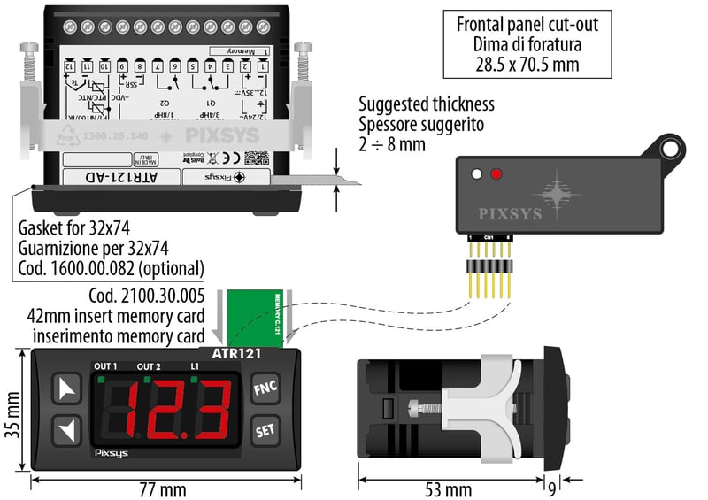
Accessories
-

Adapters and Cover plates
-
DIN Rail mounting kit
-
Memory Cards