
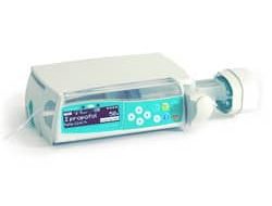
Автоматизированная шприцевая инфузионная система Perfusor Space B Braun состоит из переносного электронного шприцевого насоса и принадлежностей для него. Система предназначена для проведения терапии у взрослых, детей и новорожденных, проведения периодического или непрерывного парентерального или энтерального введения растворов через клинически обусловленные доступы. Эти доступы включают внутривенный, внутриартериальный, подкожный, эпидуральный и энтеральный.
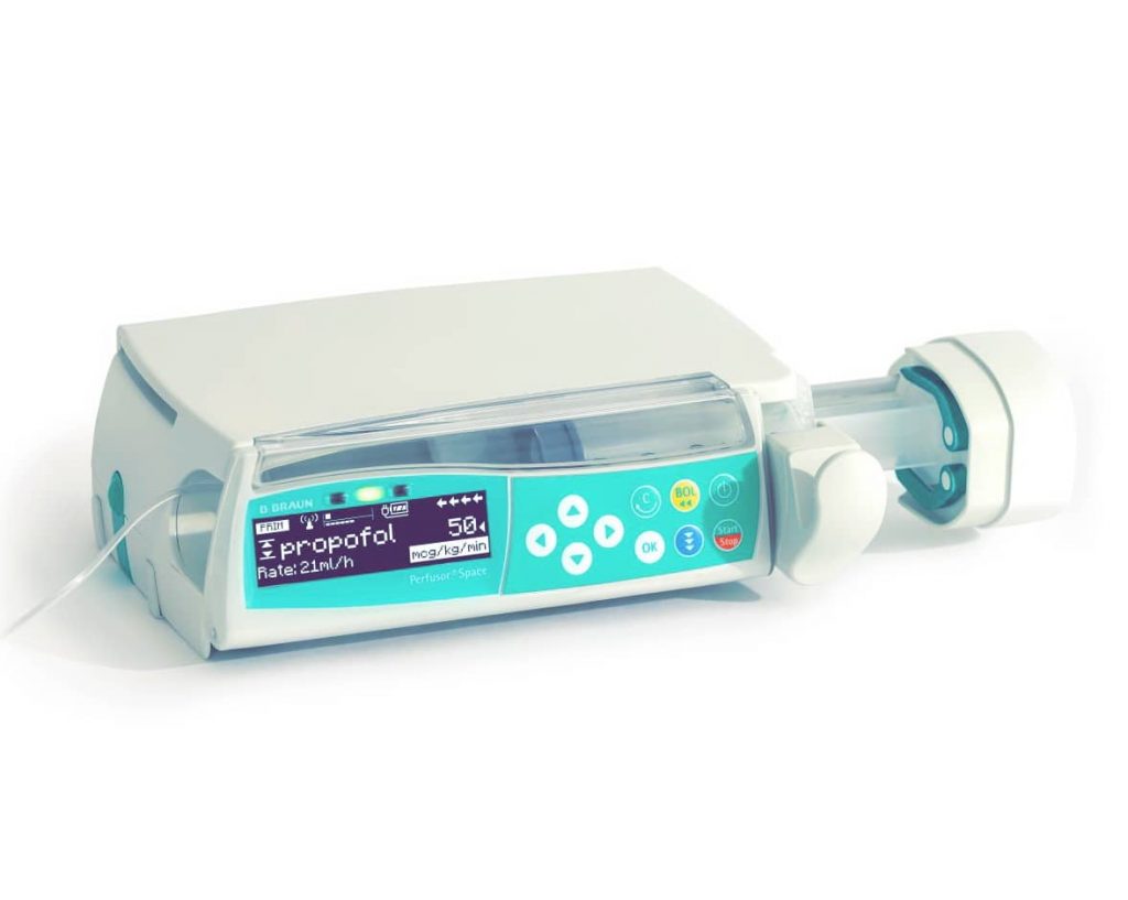
Система применяется для введения медикаментов, предназначенных для инфузионной терапии, включая анестетики, седативные, анальгетики, катехоламины, антикоагулянты и пр.; кровь и компоненты крови; полное парентеральное питание (TPN); жиры; энтеральные смеси, но не ограничивается только ими. Автоматизированная шприцевая инфузионная система Перфузор Спэйс Б. Браун предназначена для применения подготовленным медицинским персоналом в стационарных и амбулаторных лечебных учреждениях, на дому и в санитарном транспорте. Решение о применении данной системы должно приниматься квалифицированным медицинским персоналом на основании ее свойств и технических характеристик.
Производитель Perfusor Space B Braun
Производитель Перфузор Спэйс Б. Браун – B. Braun Melsungen AG, Германия. Представительство в России Б. Браун Медикал ООО, Санкт-Петербург Россия, тел. (812) 320-40-04.
Perfusor Space: Обзор
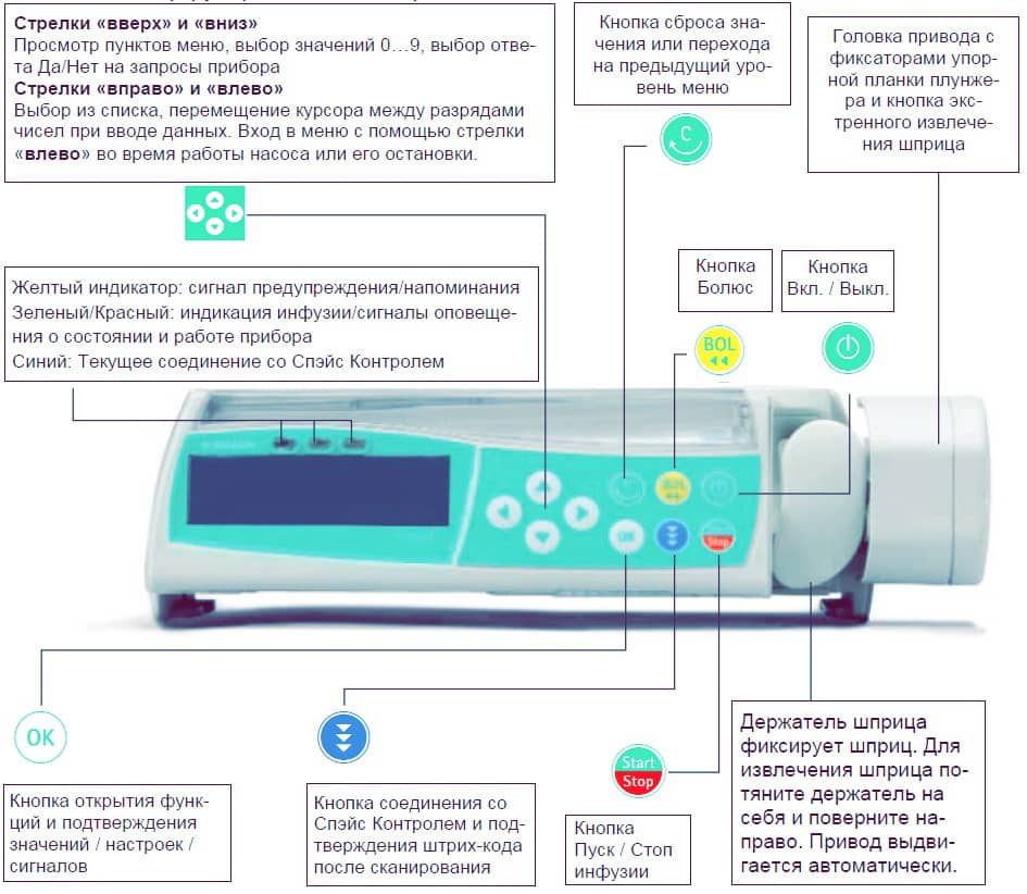
Ниже представлено описание кнопок и деталей автоматизированной шприцевой инфузионной системы Perfusor Space B Braun.
Вид спереди
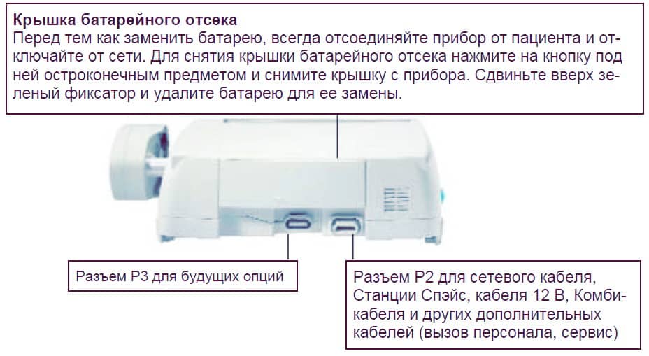
Вид сзади
Фиксация шприца
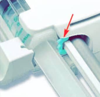
Вытяните и поверните вправо держатель шприца для открытия зеленого осевого фиксатора (см. стрелку). Перед закрытием держателя установите упорную планку цилиндра шприца вертикально в паз слева от осевого фиксатора. Убедитесь в правильном положении шприца. Не касайтесь фиксатора штока при закрытии держателя шприца.
Фиксация универсального зажима
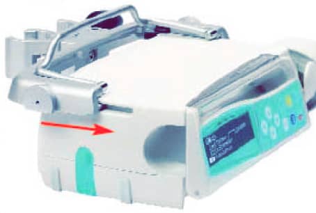
Совместите пазы в верхней части насоса с направляющими универсального зажима и двигайте рамку универсального зажима вперед до щелчка фиксатора. Для отсоединения, нажмите на кнопку извлечения на рамке, опустите транспортную ручку рамки универсального зажима и сдвиньте рамку назад.
Соединение Perfusor Space
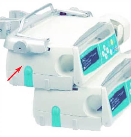
До трех насосов (Инфузомат Спэйс B braun или Перфузор Спэйс B braun) с модулем Спэйс Контроль могут стыковаться в единый блок. Остерегайтесь внешнего механического воздействия. Для соединения приборов совместите пазы нижнего насоса с направляющими верхнего и двигайте нижний насос назад до щелчка фиксатора и сопоставления зеленых кнопок друг под другом. Для отсоединения, нажмите на зеленый боковой фиксатор на верхнем насосе и выдвиньте нижний насос.
Фиксация на стойке
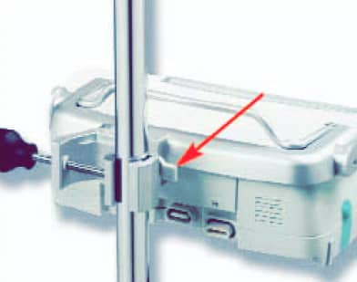
Установите зажим на вертикальной стойке и надежно закрутите винтовой фиксатор. Для снятия, открутите фиксатор. Фиксация на горизонтальной стойке: нажмите на рычаг и вращайте рамку в нужную сторону до фиксации в новом положении со щелчком. Для смены положения снова отожмите рычаг.
Управление Perfusor Space
- Первичный инструктаж по работе с Перфузором Спэйс проводится представителем Б. Браун или уполномоченным лицом. После обновления программного обеспечения Пользователь должен быть проинформирован об изменениях в работе прибора и принадлежностей, описанных в Руководстве по применению.
- Убедитесь, что прибор надежно установлен и закреплен. Не устанавливайте насос над пациентом.
- Перед применением осмотрите насос для исключения повреждений, некомплекта или загрязнений, проверьте аудиовизуальные сигналы самотестирования.
- Подключение к пациенту разрешается только после того, как шприц правильно установлен в насос, зафиксирован захватами привода и линия заполнена раствором. Перекрывайте соединение во время смены шприца для предупреждения неправильного дозирования лекарства.
- Выберите шприц/катетер сообразно предстоящему применению.
- Установите инфузионную линию, избегая перегибов.
- Рекомендуется менять расходные материалы каждые 24 часа (или в соответствие с государственными гигиеническими нормативами).
- Установка в медицинских помещениях должна соответствовать существующим требованиям (напр. VDE 0100, VDE 0107 или постановлениям IEC). Соблюдайте установленные требования и нормативы по безопасности.
- Для предупреждения риска взрыва, не используйте насос в зоне применения огнеопасных анестетиков.
Безопасность пациента
- Сравните введенные параметры с данными экрана. Начинайте инфузию только при полном соответствии параметров.
- При использовании системы вызова персонала, рекомендуется ее проверка после подключения инфузионных насосов.
- Оберегайте прибор и кабель питания от воздействия влаги.
- Не держите насос за привод при переноске.
- В случае падения насоса или внешнего силового воздействия на него, прибор должен быть проверен сервисной службой.
- Данные, отображаемые на экране должны всегда проверяться персоналом до принятия следующего клинического решения.
- Применение насоса как мобильного устройства (при домашнем уходе, внутри- и внебольничной транспортировке пациента): Убедитесь, что прибор надежно установлен и закреплен. Смена положения и сильное сотрясение могут привести к незначительным изменениям точности инфузии.
- При проведении инфузионной терапии в критических ситуациях, обязателен дополнительный мониторинг пациента.
- Избегайте внешнего воздействия на привод во время инфузии.
- При введении высокоактивных лекарств, подготовьте второй насос с тем же лекарством.
- Независимо от заданных мягких ограничений, вводимые значения должны соответствовать клиническому состоянию данного пациента.
- При изменении параметров, влияющих на расчет дозы, значение скорости всегда будет меняться, а значение дозировки будет скорректировано.
Рекомендации по применению
- Используйте только устойчивые к давлению линии (мин. 2 бар / 1500 mmHg).
- При подсоединении нескольких инфузионных линий к одному венозному доступу не исключается вероятность взаимного влияния линий.
- Касательно возможной несовместимости оборудования и лекарств, обратитесь к соответствующей информации производителей.
- Используйте только совместимые комбинации приборов, аксессуаров, рабочих компонентов и одноразовых принадлежностей с винтовым соединением.
- Использование несовместимых одноразовых принадлежностей может влиять на технические характеристики прибора.
- Подключаемые электроприборы должны соответствовать требованиям IEC/EN (напр. IEC/EN 60950 для оборудования по обработке данных). Пользователь несет всю ответственность за конфигурацию системы при подключении дополнительного медицинского оборудования. Должен быть принят во внимание международный стандарт IEC/EN 60601-1-1.
Список лекарств
До 720 наименований лекарств, включая параметры инфузии и информацию о лекарстве, могут быть сохранены в 15 категориях. Загрузка списка в насос может быть произведена с помощью отдельной компьютерной программы “Drug List Editor Space” (Редактор Списка Лекарств Спэйс).
Список лекарств доступен из Меню Пуск и Меню Специальные функции. Перед началом применения Списка, Пользователь должен убедиться, что Список лекарств в насосе соответствует данной группе пациентов. Наименование Списка лекарств будет отображено на экране насоса.
Существует несколько способов вызова Списка лекарств из Меню для последующего применения. Это возможно как во время инфузии, так и при остановке насоса.
С одной стороны, наименование лекарства со всеми параметрами инфузии может быть выбрано из Списка лекарств. С другой стороны, если скорость, объем и/или время уже были заданы в Главном меню, загружаются наименование лекарства и вновь заданные параметры инфузии. Если расчет дозы уже начат, последующее использование наименования лекарства из списка все равно возможно.
Блок данных
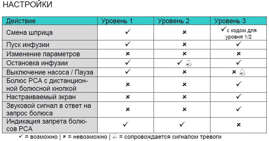
Функция Блок данных защищает прибор от несанкционированного доступа. Четырехзначный код (по умолчанию 9119), который может быть изменен через сервисную программу, активирует эту функцию. Существует три уровня защиты.
Уровень 1
Изменение значений, как и болюсная инфузия недоступны, но можно произвести смену шприца. Возможна навигация по разделам меню и проверка состояния насоса в меню Статус. Пуск, остановка и выключение насоса доступны.
Уровень 2
Этот уровень имеет те же характеристики, что и Уровень 1, но в дополнение к предыдущему, не позволяет произвести смену шприца. Для того, чтобы предотвратить активацию сигнала тревоги «Блок данных», необходимо ввести правильный код в течение 20 секунд после остановки насоса. Смена системы и выключение насоса возможны только после ввода правильного кода.
Уровень 3
Этот уровень позволяет начать и остановить инфузию, а также выключить насос. Код для этого уровня может быть различным для разных лекарств и устанавливается в Списке лекарств. Смена шприца, тем не менее, возможна с использованием кодов, установленных для двух предыдущих уровней.
Обзор различий между уровнями 1, 2 и 3 дан в таблице.
Сигналы и тревоги Perfusor Space B Braun
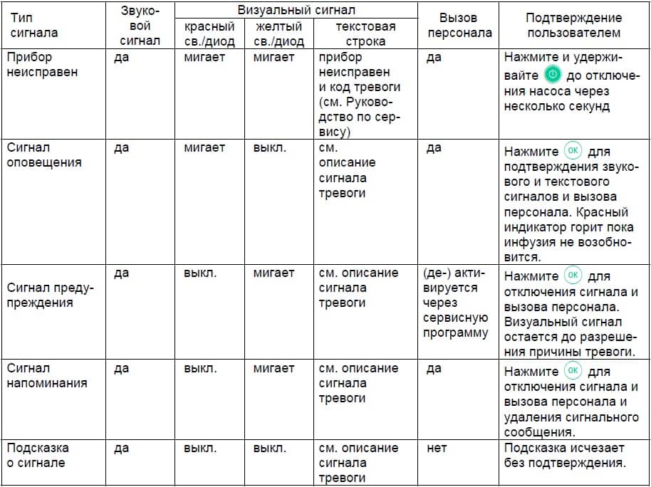
Перфузор Спэйс б браун оснащен звуковой и визуальной сигнализацией тревоги.
Сигналы неисправности Perfusor Space B Braun
При появлении сигнала неисправности прибора инфузия немедленно прекращается. Нажмите кнопку вкл/выкл для отключения прибора. Затем включите прибор снова. При повторном сигнале тревоги, отсоедините насос от пациента, откройте переднюю дверцу насоса и удалите шприц. Прибор необходимо передать в сервисную службу.
Сигналы предупреждения Perfusor Space B Braun
Сигналы предупреждения подаются за несколько минут (в зависимости от сервисных установок) перед сигналами оповещения. Сигнал предупреждения включает звуковой тон, мигающий желтый индикатор и активирует систему вызова персонала (опция). Текстовое сообщение зависит от причины тревоги. Звуковой тон и система вызова персонала отключаются нажатием кнопки «ОК». Экран и индикатор остаются в режиме предупреждения вплоть до отключения сигнала оповещения. Во время подачи сигнала предупреждения инфузия не прерывается.
Шприц почти введен
В шприце осталось очень мало жидкости.
Объем почти введен
Введение заданного объема близко к завершению.
Время истекает
Заданное время инфузии скоро истечет.
Батарея разряжается
Батарея почти разряжена.
KVO активен
Объем введен/Время истекло и насос продолжает инфузию в режиме KVO — Открытая вена.
Ошибка соединения
Насос установлен в систему, хотя бы один из приборов в которой несовместим или неисправен. Применение этого прибора в системе не разрешается. Систему необходимо передать для проверки в сервисную службу.
Таймер на экране ведет обратный отсчет оставшегося времени ( в зависимости от сервисной настройки, от 3 до 30 мин). После этого насос подает сигнал оповещения.
Сигналы оповещения Perfusor Space B Braun
Сигналы оповещения приводят к прерыванию инфузии. Подается звуковой сигнал, мигает красный индикатор и активируется система вызова персонала. На экране появляется сообщения «Тревога» и информация о причине сигнала тревоги. Звуковой сигнал и система вызова персонала могут быть отключены кнопкой «ОК». Коррекция должна быть произведена в соответствие с причиной сигнала тревоги.
Шприц пуст
В шприце не осталось жидкости. Из-за различий в допусках шприцев разных производителей, незначительное количество раствора в шприце может оставаться. Попытка продолжить инфузию приводит к полному опорожнению шприца и отключению через датчик давления. Выполните смену шприца.
Объем введен
Заданный объем введен. Продолжите инфузию или введите новые параметры.
Время истекло
Заданное время инфузии истекло. Продолжите инфузию или введите новые параметры.
Батарея разряжена
Батарея разряжена. Подключите прибор к сети и/или замените батарею. Сигнал о разрядке батареи длится 3 минуты, после этого насос автоматически отключается.
KVO остановлен
Время работы в режиме KVO истекло. Продолжите инфузию или введите новые параметры.
Высокое давление
Обнаружена окклюзия в системе. Достигнут установленный уровень давления. Насос автоматически снижает скорость введения. Проверьте отсутствие петель и перегибов инфузионной линии, проходимость инфузионного фильтра и в/в катетера. Увеличьте уровень окклюзионного давления, если необходимо. Из-за различия в допусках шприцев разных производителей, тревога по давлению может быть обусловлена высокой силой трения между поршнем и цилиндром.
Шприц установлен неверно
Упорные планки цилиндра и штока установлены неправильно.
Держатель шприца
Держатель шприца быль открыт во время инфузии. Закройте держатель шприца.
Крышка батарейного отсека удалена
Крышка батарейного отсека установлена неправильно. Переустановите крышку до щелчка.
Привод заблокирован
Внешние помехи препятствуют движению привода. Устраните все внешние помехи.
Откалибруйте прибор
Параметры калибровки насоса были изменены (например, после обновления программного обеспечения). Выполните калибровку через сервисную программу. Выполняется Сервисной службой.
Захват неисправен
Была нажата кнопка экстренного извлечения шприца и захваты были разведены вручную. Удалите шприц и обратитесь в Сервисную службу.
Планка штока не зафиксирована
Планка штока шприца не контактирует с датчиком давления насоса. Проверьте систему на наличие отрицательного давления и устраните причину.
Время паузы истекло
Установленное время паузы истекло. Задайте новое время паузы или возобновите предыдущую инфузию.
Батарея не установлена
Использование насоса без батареи невозможно. Отключите прибор и установите батарею.
Данные сброшены
Данные инфузии и насоса не возможно восстановить. Введите данные инфузии и настройки насоса заново.
Данные инфузии сброшены
Параметры инфузии не возможно восстановить. Введите параметры инфузии заново.
Блок данных
Была попытка остановить или отключить насос без ввода кода. Введите правильный код для соответствующего продолжения инфузии или выключите насос.
Красный индикатор не гаснет до возобновления инфузия или выключения насоса.
Если на экране появляется символ гаечного ключа и/или одновременно мигают желтый, красный и синий индикаторы – насос находится в сервисном режиме и его использование для лечения пациентов запрещено. Насос должен быть проверен сервисной службой.
Сигналы напоминания Perfusor Space B Braun
Сигналы напоминания подаются в двух случаях:
- Шприц установлен, инфузия не начата, значения не введены и прибор не работает в течение 2 минут. Включается звуковая сигнализация, мигает желтый индикатор и активируется система вызова персонала. Сообщение на экране «Сигнал напоминания!»; Сообщение на экране «Ввод параметров не завершен!». Для прекращения подачи сигнала тревоги нажмите «ОК» и продолжите ввод параметров инфузии и настроек насоса.
- Ввод данных начат, но не завершен или не подтвержден. Другая причина – шприц не установлен. Включается звуковая сигнализация, сообщение на экране «Значение не принято», мигает желтый индикатор и активируется система вызова персонала. Для прекращения подачи сигнала тревоги нажмите «ОК» и продолжите ввод параметров инфузии.
Подсказки о причинах сигналов тревоги
При некорректном вводе параметров, на экране появляются соответствующие подсказки, например «Внимание! Значение скорости превышает допустимое»; «Значение не может быть изменено». Включается звуковая сигнализация. Подсказки исчезают через несколько секунд и их подтверждение не требуется.
Работа от батареи и обслуживание
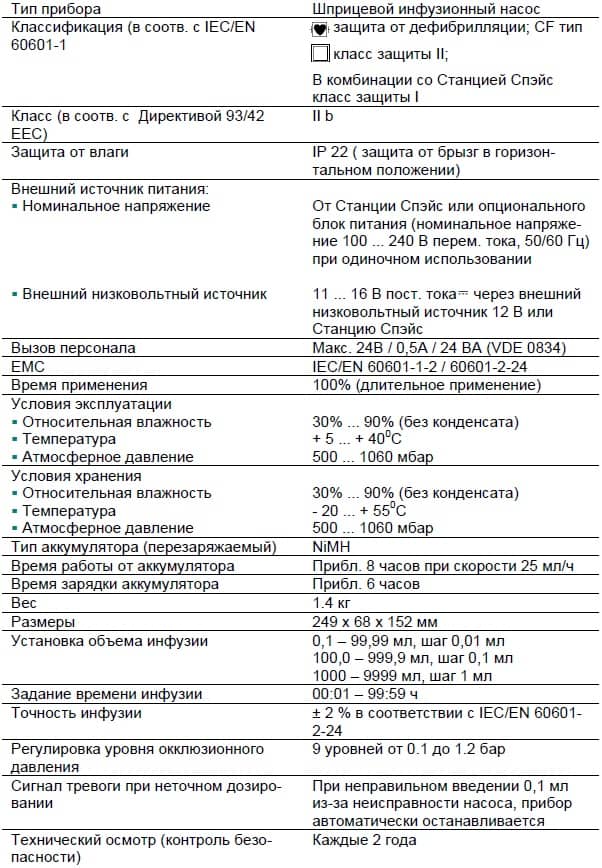
Перфузор Спэйс оснащен современной NiMH батареей. Время работы насоса с новой батареей составляет 8 часов при скорости инфузии 25 мл/ч. Для оптимальной работы аккумулятора, насос имеет защиту от перегрузки и полной разрядки. Батарея заряжается при включении прибора в сеть. При отключении от сети или в случае падения напряжения, насос автоматически переходит на питание от батареи.
Перед длительным хранением насоса (более 2-х недель без использования), батарея должна быть полностью заряжена, а затем извлечена из насоса. Перед извлечением (сменой) батареи всегда отсоединяйте насос от пациента и отключайте прибор.
Индикатор заряда батареи отображается на экране (низкий, средний, полный заряд). Для получения более детальной информации о состоянии батареи (время работы в часах и минутах) необходимо в меню «Статус» войти в раздел «Батарея».
Самотестирование батареи Perfusor Space B Braun
Если символ батареи мигает во время работы от сети, батарея либо разряжена, либо быстро разряжается. В этом случае насос не должен отключаться от сети. Если необходимо экстренно отключить насос от сети, убедитесь, что остаточный заряд батареи достаточен для применения. Если символ батареи мигает непрерывно (>1ч), батарея должна быть проверена техническим персоналом и замене-на при необходимости.
Оптимальное использование батареи
Факторы, влияющие на срок службы батареи:
- окружающая среда;
- меняющаяся нагрузка (напр. частая подача болюсов).
Срок службы батареи можно увеличить путем ее регулярной зарядки и разрядки. Для этого насос должен работать от батареи до появления сигнала тревоги о ее разрядке. После этого прибор необходимо подключить к сети минимум на 6 часов. Рекомендуется выполнять данную процедуру один раз в месяц.
Кроме того:
- Если возможно, заряжайте батарею только после ее полной разрядки.
- Если батарея, которая не разряжена полностью, заряжается несколько раз, ее емкость может уменьшиться. Первоначальная емкость может быть восстановлена при полной разрядке и последующей зарядке батареи.
- При нормальных температурных условиях батарея может быть заряжена и разряжена приблизительно 500 раз, после чего длительность ее работы снижается.
- При отключении насоса от сети батарея медленно разряжается. Это происходит даже, когда насос не работает. Первоначальная емкость может быть достигнута после нескольких циклов зарядки и разрядки.
- Время работы батареи может быть определено только при непрерывной работе насоса с полностью заряженной батареей при комнатной температуре. Отображаемое на экране насоса приблизительное время работы батареи основывается на текущей скорости инфузии. При длительном сроке использования, реальное время работы батареи снижается.
Батареи могут взрываться и протекать при вскрытии или сжигании. Соблюдайте правила утилизации!
Обслуживание батареи Perfusor Space B Braun
Для точной регулировки емкости батареи необходимо ее циклическое обслуживание. Насос запрашивает Пользователя о проведении обслуживания батареи каждые 30 дней. В режиме обслуживания батареи определяется возможная потеря емкости (например, из-за старения батареи) и затем емкость и время работы от батареи пересчитываются заново. После длительного хранения или длительной работы без обслуживания батареи, может случиться так, что время подачи предупредительного сигнала больше не будет поддерживаться. В этом случае необходимо проведение обслуживания батареи.
Для инициализации полной разрядки батареи на экране появляется запрос «Обслуживание батареи» и отображается кнопка «ОК». Для того, чтобы запустить процесс разрядки батареи, нажмите «ОК» и «вверх». При включении насоса процесс прерывается. Если обслуживание батареи необходимо продолжить, нужно повторно активировать режим обслуживания. После полной разрядки батареи происходит ее полная зарядка. Полное обслуживание батареи длится приблизительно двенадцать часов.
Примите во внимание, что время работы от батареи может быть меньше, если обслуживание батареи не завершено.
Технические характеристики Perfusor Space B Braun
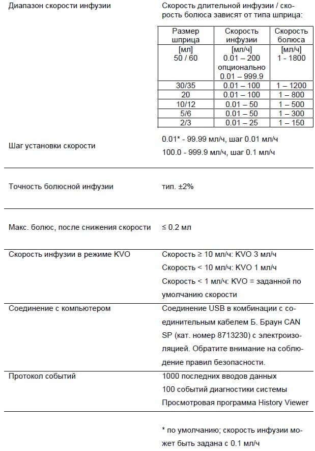
Ниже указаны технические характеристики насоса Perfusor Space B.Braun.
Гарантия Perfusor Space B Braun
Компания Б. Браун предоставляет 24 месяца гарантии, с момента поставки на каждый Перфузор Спэйс (12 месяцев на каждый аккумулятор (Battery Pack SP)). Гарантия предусматривает ремонт или замену отдельных частей, вышедших из строя в результате конструкторских или производственных ошибок, а так же дефектов материала. Срок действия гарантии прекращается в случае модернизации или ремонта, проведенных Пользователем или посторонними лицами.
Гарантия не распространяется на устранение дефектов, вызванных неправильным / неумелым обращением или нормальным износом прибора.
Регулярная проверка Perfusor Space B Braun
Проверяйте чистоту, комплектность, отсутствие повреждений. Используйте прибор только согласно Руководству по применению. При каждом включении проверьте: самотестирование, звуковой сигнал, индикацию работы и сигнализацию.
Уход Perfusor Space B Braun
Очищайте поверхность насоса с использованием мыльного раствора. Не рекомендуется применять распылители в местах контакта с электричеством. Рекомендуется: средство для протирания, например Мелисептол фирмы Б. Браун. После очистки прибор должен высохнуть в течение как минимум одной минуты. Не распыляйте в отверстия прибора. Соблюдайте инструкции по утилизации использованных расходных материалов и уходу за батареями и принадлежностями. Увеличительное стекло передней крышки и экран протирайте мягкой салфеткой. Не используйте Гексакварт.
Принадлежности и каталожные номера Perfusor Space B Braun
Б.Браун Перфузор Спэйс (871 3030)
Станция Спэйс (871 3140)
Станция Спэйс предназначена для установки до четырех насосов.
Верхняя крышка СпэйсКавер стандарт (871 3147)
Верхняя крышка СпэйсКавер комфорт (871 3145)
Верхняя крышка предназначена для установки на Станцию Спэйс. Крышка имеет встроенную ручку для переноски Станции. СпэйсКавер комфорт дополнительно оснащена центральной сигнализацией с блоком управления и сигнальными индикаторами.
Универсальный зажим Спэйс (871 3130)
Предназначен для фиксации до трех насосов Б. Браун Спэйс и одного модуля Спэйс Контроль и их стыковки в единый блок.
Блок питания Спэйс (871 3110A)
Обеспечивает питание от сети для одного насоса или для модуля Спэйс Контроль.
Комби — кабель Спэйс 12 В (871 3133)
Комби – кабель Спэйс позволяет объединить до трех насосов. Все насосы могут быть подключены через блок питания Спэйс или соединительный кабель 12 В.
Перезаряжаемая батарея Спэйс (871 3180)
Интерфейсный кабель CAN Спэйс (871 3230)
Интерфейсный кабель CAN Спэйс требуется для соединения Станции Спэйс / насоса Спэйс с компьютером (для сервисных целей).
Соединительный кабель Спэйс 12 В (871 3231)
Кабель Спэйс для системы вызова персонала (871 3232)
Используйте указанный соединительный кабель для подключения насоса Перфузор Спэйс к системе вызова персонала. Подключение к системе вызова персонала необходимо для выполнения требований VDE 0834.
Оригинальные шприцы Perfusor Space B Braun
- Шприц Перфузор 50 мл без иглы, ЛЛ (872 8844F);
- Шприц Перфузор 50 мл c иглой, ЛЛ (872 8810F);
- Шприц Перфузор 50 мл c иглой и фильтром, ЛЛ (872 8852F);
- Шприц Перфузор 50 мл c иглой и фильтром, светозащитный, ЛЛ (872 8828F);
- Шприц Перфузор 20 мл без иглы, ЛЛ (872 8615);
- Шприц Перфузор 20 мл c иглой, ЛЛ (872 8623);
- Шприц Омнификс 50/60 мл, ЛЛ (461 7509F);
- Шприц Омнификс 30 мл, ЛЛ (461 7304F);
- Шприц Омнификс 20 мл, ЛЛ (461 7207V);
- Шприц Омнификс 10 мл, ЛЛ (461 7100V);
- Шприц Омнификс 5 мл, ЛЛ (461 7053V);
- Шприц Омнификс 2 мл, ЛЛ (461 7029V).
Оригинальные линии Perfusor Space B Braun
- Линия Перфузор, ПВХ, 50 см (825 5172);
- Линия Перфузор, ПВХ, 150 см (872 2960);
- Линия Перфузор, ПВХ, 200 см (872 2862);
- Линия Перфузор, ПВХ, 250 см (825 5490);
- Линия Перфузор, ПВХ, 300 см (825 5253);
- Линия Перфузор, ПЭ, 50 см (825 5059);
- Линия Перфузор, ПЭ, 100 см (825 5067);
- Линия Перфузор, ПЭ, 150 см (872 2935);
- Линия Перфузор, ПЭ, 200 см (872 3060);
- Линия Перфузор, ПЭ, 250 см (827 2565);
- Линия Перфузор, ПВХ, 150 см, безыгольный коннектор Сэйфсайт (872 2820);
- Линия Перфузор, ПВХ, 200 см, инъекционный фильтр 0,22 мкм (872 3001);
- Линия Перфузор, ПВХ, 168 см, PCA, с возвратным клапаном (872 6019);
- Линия Перфузор, тип МР, ПВХ, 75 см, с перекидной гайкой (872 2870);
- Линия Перфузор, тип МР, ПВХ, 150 см, с перекидной гайкой (825 5504);
- Линия Перфузор, ПЭ, 150 см, светозащитная (872 3010).
Скачать инструкцию на Perfusor Space B Braun
Скачать инструкцию и другую документацию на Perfusor Space B Braun можно здесь.
Руководство пользователя ( user manual ) на русском языке Perfusor Space B Braun скачать.
Сервисная инструкция ( service manual ) на английском языке Perfusor Space B Braun скачать.
Регистрационное удостоверение Perfusor Space B Braun скачать.
Так же смотрите Space Control, Инфузионный насос DI 2000 Medifusion, Инфузионный насос Aitecs DF-12M.
Перфузор компактплюс
Быстрый поиск по продуктам
Шприцевой инфузионный насос — простой, безопасный, надежный
Компактплюс— новое поколение инфузионных насосов Б. Браун с большим цветным экраном, пошаговой установкой шприца, интуитивным управлением, встроенной системой контроля дозировки DoseGuard™ и литий-ионной батареей. Компактплюс объединяет в себе последние технические достижения и, в тоже время, сохраняет простоту и надежность насосов поколения компакт.
Преимущества
- Цветной дисплей высокого разрешения
- Видимость со всех углов (80°)
- Библиотека лекарств с цветовой кодировкой групп препаратов
- Интуитивное управление с пошаговой инструкцией на русском языке
- Встроенный блок питания
- Встроенные зажим и ручка для переноски
- Полуавтоматический привод
- Литий-ионная батарея
- Увеличенный срок службы аккумулятора с высоконадежными литий-ионными элементами
- Время зарядки всего 3 часа
- Влагозащита IP34 (защита от брызг с любого направления)
0 — 10
Perfusor® compact S
Service-Manual
Version 2.1 english
0 —
0
This Service-Manual is valid for
This Service Manual is available under the following part number:
Languages of this Manual
The complete Service-Manual contains the following pages:
Designation Part No.
Perfusor® compact S (200 — 240 V) . . . . . . . . . . . . . . . 0871 4843
Designation Part No.
Perfusor® compact S, English . . . . . . . . . . . . . . . . . . . . 8713 9114
The Service Manual for this unit can be supplied in the following languages:
Designation Part No.
Perfusor® compact S, German . . . . . . . . . . . . . . . . . . . . 8713 9113
Perfusor® compact S, USA . . . . . . . . . . . . . . . . . . . . . . .8713 9115
Page 0-1 to page 0-10
Page 1-1 to page 1-4
Page 2-1 to page 2-8
Page 3-1 to page 3-14
Page 4-1 to page 4-18
Page 5-1 to page 5-8
Page 6-1 to page 6-2
Page 7-1 to page 7-2
Page 8-1 to page 8-6
Page 9-1 to page 9-2
Page 10-1 to page 10-2
Page 11-1 to page 11-2
Page A-1 to page A-2
0 — 2 Perfusor® compact S, 2.1 gb
Contact Persons
System Overview
Software
Service Program
Unit Elements
Important Preliminary Remarks
0 —
Table of Contents
0
Service Work
Technical Safety Checks
Current Versions
Revision Service
Quality Management
Checks and Repair
Notes on ESD
Spare Parts and Test Equipment
Setting Off
List of Abbreviations
Technical Training
Entry for Technical Training
Ordering of Spare Parts and Test Equipment
Service Hotline
Return of Spare Parts and Test Equipment
Safety Officer
(§ 30 MPG)
Translation
Physical Construction
Function
Accessories
Page 1 — 1
Page 1 — 2
Page 1 — 3
Approved Software Versions
Version Display during Switch-On Test
Page 2 — 1
Page 2 — 1
Extended Version Display during Switch-On Test Page 2 — 2
Error Messages and Alarms Page 2 — 3
Page 0 — 5
Page 0 — 5
Page 0 — 5
Page 0 — 5
Page 0 — 6
Page 0 — 6
Page 0 — 6
Page 0 — 7
Page 0 — 7
Page 0 — 8
Page 0 — 9
Page 0 — 9
Page 0 — 9
Page 0 — 9
Page 0 — 9
Page 0 — 9
Page 0 — 9
Current Service Program
Introduction
Working with the Service Program
What to Do if… (Troubleshooting)
Menu Commands (Overview)
Procedural Instructions for Inspection
Page
Page
Page
Page
Page
3 — 1
3 — 1
3 — 2
3 — 5
3 — 7
after Operation of the Service Program Page 3 — 11
Checklist after Operation of the Service Program Page 3 — 13
Fundamental Repair Information
Syringe Table and Quick Reference Guide
Syringe Holder
Unit Feet
Battery Compartment Cover
Snap-in Clip
A-Module
LS-Clip
E-Module
N-Module
Housing Upper Part, Complete
Carrying Handle
Drive
Page 4 — 1
Page 4 — 4
Page 4 — 4
Page 4 — 5
Page 4 — 5
Page 4 — 6
Page 4 — 6
Page 4 — 7
Page
Page
Page
Page
Page
4 — 8
4 — 9
4 — 9
4 — 10
4 — 11
0 — 3 Perfusor® compact S, 2.1 gb
0
Table of Contents
Checks after Repair
Maintenance
Technical Safety Check TSC
Procedural Instructions on the TSC
Test Equipment and Special Tools
Spare Parts List
Index
Appendix
Axial Positioner
Drive Board
Drive Head and Holder
Clip
Drive Head Housing
Housing Bottom Part, Complete
Check List for Checks after Repair
Visual Inspection
Functional Inspection
Electrical Safety
Syringe / Syringe Selection
Adhesive Label Factory Setting
Visual Inspection
Functional Inspection
Syringes
Pressure Cut-Off
Electrical Safety
Accessories
Revision Service-Documentation
Current Information
Page 4 — 12
Page 4 — 12
Page 4 — 14
Page 4 — 17
Page 4 — 18
Page 4 — 18
Page 5 — 1
Page 5 — 2
Page 5 — 2
Page 5 — 8
Page 5 — 8
Page 5 — 8
Page 6 — 1
Page 7 — 1
Page 8 — 1
Page 8 — 2
Page 8 — 3
Page 8 — 3
Page 8 — 5
Page 8 — 5
Page 9 — 1
Page 10 — 1
Page 11 — 1
Page A — 1
Page A — 1
0 — 4 Perfusor® compact S, 2.1 gb
Service Work
Technical Safety Checks
Current Versions
Revision Service
0 —
Important Preliminary Remarks
0
The present manual is for your information only. The possession of this manual does not authorize the performance of service work.
Service tasks may only be executed by persons, who
have received appropriate training on the system from
B. Braun
are included in the revision service
possess the necessary test equipment and mechanical aids, and
fulfill the personal requirements (training and knowledge).
The user is obliged to perform or to have performed the Technical
Safety Checks on those medial products for which these checks have been prescribed by the manufacturer and to carry them out according to the indications of the manufacturer as well as the generally approved technical standards while adhering to the periods stated (§ 6 MP BetreibV).
B. Braun also recommends training on the Technical Safety
Checks, or to perform at least the steps indicated in the current version of the manual, as:
the TSC requires that the instructions in the manuals are observed
the manuals are a reference for measurements
depending on the unit type, the Service Program must be called which may lead to a dangerous unit condition in case of inappropriate operation. Furthermore, a special service connector may be necessary.
This manual version corresponds to the state when the manual was written. B Braun reserves the right to make technical modifications. The state of the revision is indicated by the index number in the footer of every page.
The possession of this manual does not automatically mean inclusion in the revision service. You will be included in the revision service after:
technical training by B. Braun Melsungen or
a written order placed with the sales department of B. Braun
(fee required).
Perfusor® compact S, 2.1 gb 0 — 5
0
Important Preliminary Remarks
Responsibility of the Manufacturer
Quality Management
Checks and Repair
Notes on ESD
The manufacturer, person who assembles, installs or imports the device can only be held responsible for safety, reliability and performance if
mounting, enhancements, new settings, changes or repairs are carried out by duly authorized persons,
the electrical installation in the corresponding room meets the requirements of the VDE 0107, VDE 0100 part 710 or
IEC 60364-7-710 and the national standards,
the device is used in accordance with the instructions for use and the Service Manual,
the Technical Safety Checks are performed at regular intervals,
a current manual which corresponds to the revision state is used when carrying out maintenance, repair and service,
the service technician takes part in the revision service,
the technician has participated in a technical training course for the specific B. Braun unit.
B. Braun is certified in accordance with DIN EN ISO 9001 and
ISO 13485. This certification also includes maintenance and service.
The unit has the CE label. The CE label confirms that the device corresponds to the “Directive of the Council for Medical Products
93/42/EC” of June 14, 1993.
Training may only be performed by B. Braun. The possession of the manual does not authorize the performance of repairs. The instructions on electrostatic sensitive components (ESD standards) must be observed.
After repair a device check or diagnosis is to be carried out.
Semiconductors can be destroyed by electrostatic discharge. Especially MOS components can be damaged by interference from electrostatic fields, even without discharge via contact. This type of damage is not immediately recognizable. Unit malfunctions can even occur after a longer period of operation.
0 — 6 Perfusor® compact S, 2.1 gb
Fig.: 0 — 1
Spare Parts and Test Equipment
Setting Off
Important Preliminary Remarks
0
Each workstation must be equipped according to the recommendations with the necessary static protective measures, if ESD components or boards are handled.
Each workstation must be equipped with a conductive table surface. The conductive surface, the soldering iron or the soldering stations must be grounded via protective resistors.
Chairs must be of antistatic design. The floor or floor mats should be of electrically conductive material.
Personnel must wear conductive wristbands which are connected to a central ground potential via protective resistors, e.g. the ground contact of a wall outlet. Furthermore it is recommended that personnel wear cotton clothing and electrically conductive shoes to prevent electrostatic charge.
Only use original spare parts from the manufacturer. Do not tamper with assembly groups which can only be exchanged completely. The spare parts required are listed in Section 9.
Service personnel are responsible for the calibration of their test equipment. Original test equipment can be calibrated at the works of B. Braun. Further information is available upon request.
Additional notes and warnings are set off as follows:
Note
Is used for additional or special notes concerning information and working steps.
CAUTION
Is used for working steps which may result in damage to the unit, system or to a connected device.
WARNING
IS USED FOR WORKING STEPS WHICH MAY RESULT IN PERSONAL
INJURY.
References to chapters are shown as follows
(see “Setting Off“
➨ pg. 0 —
References to figures and tables are shown as follows
Fig.: 2 — 3 or Table 2 — 1
0 — 7 Perfusor® compact S, 2.1 gb
0
Important Preliminary Remarks
List of Abbreviations
References to item numbers in figures are shown as follows
( Fig.: 1 — 1 / Item 1 )
In this case “Fig.: 1 – 1“ is the figure number and “Item 1“ the item number within the figure.
When the Service Manual is stored as pdf-file, these references are displayed green. Click with the mouse button on a reference to jump to the corresponding source.
Menu commands are described as:
Menu
File
.
Abbreviations which are not generally known, but are used in this manual, are listed below.
DMS Strain gauge
LCD
PS-Module
Liquid Crystal Display
Power Supply Module
Checks
TEMP Temperature
0 — 8 Perfusor® compact S, 2.1 gb
0 — 10
Technical Training
Entry for Technical Training
Ordering of Spare Parts and Test Equipment
Service Hotline
Return of Spare Parts and Test Equipment
Safety Officer
(§ 30 MPG)
Translation
0 —
Contact Persons
0
Via local representative.
Application for a technical training course must be made via the responsible representative.
Please contact your local B. Braun subsidary.
International Technicians (Intercompany)
Nadja Machal
Fax: +49 5661 / 75 -47 89 e-mail: [email protected]
Karl Tippel, Tanja Kördel
Phone: +49 5661 / 71 — 35 25
Fax: +49 5661 / 71 — 35 26 e-mail: [email protected]
e-mail: [email protected]
B. Braun Melsungen AG
Schwarzenberger Weg 73-79
Wareneingang Werk C
34 212 Melsungen
Germany
Dr. Dirk Woitaschek e-mail: [email protected]
PAS GmbH, Brückner GmbH, Germany
Perfusor® compact S, 2.1 gb 0 — 9
0
Contact Persons
For your notes:
0 — 10 Perfusor® compact S, 2.1 gb
1 — 4
Physical Construction
.
Carrying handle Membrane keyboard
1 —
System Overview
1
The Perfusor® compact S is a compact, stacking, portable and light-weight syringe pump which is used for precise dosing of small to high volumes of fluids in infusion and alimentary therapies.
The standard delivery rate range is 0.1 to 200 ml/h (in increments of 0.01 ml/h).
All important information is displayed on an LCD-display. The Perfusor® compact S features: simple operation via a membrane keyboard and a microprocessor-controlled function process and monitoring. The Perfusor® compact S has a long service life and is easy-to-service due to its modular design. Individual modules can be replaced easily and quickly, and the Service Program runs on a
PC.
MFC-socket
Battery compartment
LCD-display
Syringe holder
Axial positioner Drive head with lock and push-button sensor
Axial positioner
Type plate
Clamp
Syringe table and quick reference guide
Mains connection
Snap-in clip
(on both sides)
Unit feet
View from below
Fig.: 1 — 1
Perfusor® compact S, 2.1 gb 1 — 1
1
System Overview
Function
The electronics of the Perfusor® compact S consists of the following components:
1.
A-Module with MFC-board as the central power supply and interface
2.
E-Module as operating and control unit
3.
Drive unit, consisting of
drive board with the complete sensor technology, light barriers for syringe pre- and end-alarm, syringe size recognition and motor operation control
pressure sensor board with sensor for an inserted syringe and force sensor amplifier
positive locking sensor board with sensor for the frictional connection between nut and spindle of the drive
pressure sensor (pressure).
Fig.: 1 — 2 Block diagram
1 — 2 Perfusor® compact S, 2.1 gb
Accessories
System Overview
1
Designation Ord. No.
Unit connecting lead 220-240 V . . . . . . . . . . . . . . . . . 3450 2718
Pole clamp (universal clamp, rotating) . . . . . . . . . . . . 3450 9054
Battery pack . . . . . . . . . . . . . . . . . . . . . . . . . . . . . . . . . 3450 1690
Perfusor® compact S, 2.1 gb 1 — 3
1
System Overview
For your notes:
1 — 4 Perfusor® compact S, 2.1 gb
2 — 8
2 —
Software
2
Approved Software Versions
Position
Digit
1 2 3 4 5 6 7 8 9
P L B E 0 0 0 1 4
Revision level
Hardware identification
Software group
Hardware group
Perfusor® compact S
Fig.: 2 — 1
Version Display during Switch-On Test
The software and hardware revision level is displayed on the LCDdisplay when the unit is switched on. The characters on the display must correspond with the indication on the instructions for use.
Version PLBD00010
Version PLBE00010
Version PLBE00011
Version PLBE00013
Version PLBE00014 first approved software version with Dianet Star with Dianet Star and modified signalling in case of a missing battery
Dianet Star, enhanced with Dianet Star and modified syringe size recognition
1.
Switch on unit.
2.
The following information is displayed one after the other on screen:
88:8.
8
11:1.
1
22:2.
2
55:5.
5 b:E.
Reference to the instructions for use (hard- and software group)
3.
The Perfusor® compact S switches over to normal operation.
Perfusor® compact S, 2.1 gb 2 — 1
2
Software
Extended Version Display during Switch-On Test
1.
Switch on unit.
2.
Press the F button and keep the button pressed during normal switch-on test. The following information (examples) appears on screen after the information displayed during normal switch-on test:
(no importance for the
Perfusor® compact S)
0063 0063 operating hours
3.
Release the F button to exit. The Perfusor® compact S switches over to normal operation.
2 — 2 Perfusor® compact S, 2.1 gb
Error Messages and Alarms
34
40
45
46
30
31
32
33
47
48
49
51
52
21
22
28
29
7
8
12
20
5
6
3
4
LCD-Display
1
2
Table 2 — 1 (Part 1 of 3)
Description
Different syringe recognition
Different FP- and CMP condition
Rate of FP- and CMP different
Different function mode
Different rate of delivery
Different target volume
Different step volume (low)
Different motor steps
Different state/motor state
Invalid normal state return from PlcMain
Unexpected reset
No sync at Plc_Down
No sync at Plc_On
Different CMP/FP mode ports
Invalid mode ports
Invalid variable values
Error in ROM test
Different software version
Unexpected interrupt
Potentiometer faulty
Verst.umsch. / DAC faulty
Pressure too low
Buffer filling too high
Faulty sensor sync
Motor on during reverse run
Step cumulation > 10 steps
Software
2
In case of a unit malfunction a continuous signal is activated, and the function processor displays an alarm and an error code. The error code of the control microprocessor can be queried with the
F button. Please state both error codes if you have any questions.
Acknowledge alarm and switch device off.
Device Alarms of the Function Processor
Perfusor® compact S, 2.1 gb 2 — 3
2
Software
99
100
101
102
92
93
94
95
103
104
105
109
85
86
90
91
81
82
83
84
71
72
73
75
61
62
63
70
55
56
57
59
LCD-Display
53
54
Table 2 — 1 (Part 2 of 3)
Description
Illegal setting of Mot_Ok
Diff. result of direction of rotation recognition
Reverse polarity of motor
Invalid syringe
Overflow of motor step counter
No sync at Mot_Test
Different SW button NEC<>H8
Timeout KBD watchdog
Error in switch-on test
Control timer overflow (int)
Control timer underflow
Control timer overflow
100 ms cycle overflow
Tim_WaitUntil overflow
Error upon reading of EEPROM
Error of syringe data record
Error of EEP data consistency
Ad difference between NEC/H8
Bw difference between NEC/H8
Md difference between NEC/H8
Syringe state in Oper_Syr
Set syringe type
Consistency error
Difference between setting and display
Timer synchronization
Syringe type entered
Volume/step too large
Division by zero
Illegal zero pointer
Illegal switch to default
Too many sync data
Odd number of sync data
No contact to NEC in OFF
Faulty synchronization
2 — 4 Perfusor® compact S, 2.1 gb
LCD-Display
110
111… 119
120
121
126
127
Table 2 — 1 (Part 3 of 3)
Description
Alarm on CMP side
Motor test 1 … 9
Motor current flow in OFF
Battery discharged during test
Alarm synchron. (coming)
Alarm synchron. (going)
Software
2
Perfusor® compact S, 2.1 gb 2 — 5
2
Software
176
180
181
182
161
170
171… 174
175
157
158
159
160
153
154
155
156
183
184
185
138
150
151
152
134
135
136
137
LCD-Display
128
129
130
131
132
133
Table 2 — 2 (Part 1 of 2)
Description
Unexpected reset
Unexpected hardware interrupt
Access of zero pointer
Attempted division by zero
Internal software error
Area fault
State/motor state
Invalid variable values
Invalid operating condition
Illegal mode – port value
H8 indicates GA F14_H8GA_K16
Different software versions
Double CRC error
Synchronization fault
Different states
Different rates
Different F-mode
Different mode values
Different alarm recognition
Different alarm clearance
Err. current volume
Err. volume preselection
Err. volume per step
Sensor sync. failed
Sensor — dark test error
Potentiometer holder defective
Invalid strain gauge signal
ROM test error
RAM test error
Keyboard test error column
Dynamic memory test
Motor test no sync
Keyboard test error
2 — 6
Device Alarms of the Control Microprocessor
Perfusor® compact S, 2.1 gb
Software
2
225
226
227
230
221
222
223
224
231
232
233
234
241… 249
250
251
207
208
209
220
202
203
205
206
LCD-Display
186
187
191
192
193
200
Table 2 — 2 (Part 2 of 2)
Description
Timer test error
CPU test error
Different software buttons
Keyboard timeout error
Keyboard drive error
Cycle > 100 ms
Time > Until
Watchdog interrupt
Time-out when switching H8 on
Time-out when switching H8 off
No sync at Plc_Down
No sync at Plc_On
CMP/FP timer – end sync error
Different phases (busy)
Different phases (idle)
Motor on at reverse steps
Too many pending steps
Motor current error
Error of motor step number
Reverse polarity of motor
Motor steps overflow
Different syringe recognition
CMP/FP syringe state
CMP/FP syringe type set
CMP/FP syringe type set
CRC error in syringe data record
Motor test 1 … 9 errors
Motor ON recognized in OFF-mode
Battery voltage low
Note
Operating alarms are specified in the instructions for use.
Perfusor® compact S, 2.1 gb 2 — 7
2
Software
For your notes:
2 — 8 Perfusor® compact S, 2.1 gb
3 — 14
Current Service Program
3 —
Service Program
3
Designation Ord. No.
3.5» floppy disk . . . . . . . . . . . . . . . . . . . . . . . . . . . . . . . 3450 6330
Interface cable . . . . . . . . . . . . . . . . . . . . . . . . . . . . . . . 0871 1661
Introduction
Selection menu
Length calibration
Syringe calibration
Pressure calibration
Control microprocessor
Function processor
Serial number
Fig.: 3 — 1
The Service Program runs on a PC. All functions are easy to operate in the pulldown-menus as in Windows.
WARNING
NEVER RUN SERVICE MODE WHEN A PATIENT IS CONNECTED!
DO NOT CONNECT THE SERVICE CONNECTOR OR THE SERVICE CA-
BLE WHEN A PATIENT IS CONNECTED TO THE UNIT! FIRST SWITCH
THE UNIT OFF BEFORE ANY FURTHER USE AFTER WORKING WITH
THE SERVICE CONNECTOR.
CHECK UNIT ACCORDING TO THE PROCEDURAL INSTRUCTIONS
FOR INSPECTION
(see „Procedural Instructions for Inspection after
Operation of the Service Program“ ➨ pg. 3 — 11) .
When the Service Program is installed and the PC is connected to the Perfusor® compact S, the following functions can be executed:
Drive calibration
Reading / loading pump data
Displaying operation values
Displaying and changing parameters
Saving all data to a floppy disk, hard disk or similar
System Requirements
PC with WIN 95, 98, 2000 or NT
Free serial port COM 1 or COM 2
Disk drive
Mouse
Perfusor® compact S, 2.1 gb 3 — 1
3
Service Program
Working with the Service Program
1
Fig.: 3 — 2
Legend of fig. 3 — 2:
ItemDesignation
1 MFC connector on the unit
2 MFC service cable
2
Installation
1.
Insert disk.
2.
Start the File Manager or Windows Explorer.
3.
Select disk drive.
4.
Start Setup.exe file with a double click and follow the instructions. Latest information on the Service Program is documented in the Readme.txt file on the floppy disk.
Uninstall
1.
Menu bar of the PC:
Start
➨
Programs
➨
B Braun
➨
PCS
➨
Unwise.exe
. The Service Program is deleted.
Preparation
1.
Connect service cable ( Fig.: 3 — 2 / Item 2 ) to MFC connector
( Fig.: 3 — 2 / Item 1 ) of the unit and the PC serial port (COM
1 or COM 2).
2.
Connect mains cable to the unit.
Start Program
1.
Menu bar of the PC:
Start
➨
Programs
➨
B Braun
➨
PCS
➨
PCS.exe.
The Service Program is started.
Configuration
1.
Select menu
File
➨
Configuration
.
2.
Select language and port.
3.
Acknowledge with
OK
.
Connect
1.
Select menu
File
➨
Connect
and press F1 button and ON-key on the Perfusor® compact S. If the unit is connected when being switched off (calibration) and are displayed. If the unit is switched on (test syringe size recognition) is additionally displayed.
3 — 2 Perfusor® compact S, 2.1 gb
Perfusor® compact S, 2.1 gb
Service Program
3
Display / Save the Unit Settings
Read EEPROM before starting work in a menu. Write EEPROM when work is terminated.
1.
Menu
EEPROM
➨
Read
2.
Menu
File
➨
Save
3.
Menu
File
➨
Print.
Printing out the settings is a useful help.
4.
Call menu
Modes
➨
Modification
and menu
Syringes
➨
Syringe Selection
or
Syringe Types
. Note down parameters prior to any modification (e.g. new E-Module).
Adjust Unit Settings
1.
Menu
EEPROM
➨
Read
2.
Desired modifications / display, please see:
—
Operation
➨
Operating Data
—
Modification
➨
Modification Data
—
Calibration
➨
Pressure Calibration
—
Syringes
➨
Syringe Selection
—
Constants
➨
Service Interval
3.
Menu
EEPROM
➨
Write
transmits data to the device.
4.
Menu
File
➨
Save
saves the data on the hard disk.
Enter the user number 0 upon query.
5.
Carry out check according to the procedural instructions
(see
„Check List for Checks after Repair“ ➨ pg. 5 — 1)
.
Calibration after Replacement of E-Module
1.
Menu
EEPROM
➨
Default
Existing values are deleted and reset to the factory settings.
2.
Process the following menus:
—
Calibration
➨
Serial Number
—
Calibration
➨
Pressure Calibration
—
Calibration
➨
Syringe Type Calibration
—
Calibration
➨
Length Calibration
3.
Reset user settings in
Modification
➨
Modification Data
, if necessary.
4.
Reset syringe types according to specific user requirements.
Delete syringes which are not required, if necessary, load additional syringes or a syringe table which was created for the user.
5.
Menu
EEPROM
➨
Write
transmits data to the device.
3 — 3
3 — 4
3
Service Program
6.
Menu
File
➨
Save
saves the data on the hard disk. Enter the user number 0 upon query.
7.
Carry out check according to the procedural instructions
(see
„Check List for Checks after Repair“ ➨ pg. 5 — 1) .
Calibration after Replacement of Drive
1.
Menu
EEPROM
➨
Read
2.
Edit the following menus:
—
Calibration
➨
Pressure Calibration
—
Calibration
➨
Syringe Type Calibration
—
Calibration
➨
Length Calibration
3.
Menu
EEPROM
➨
Write
transmits data to the device.
4.
Menu
File
➨
Save
saves data on the hard disk. Enter the user number 0 upon query.
5.
Carry out check according to the procedural instructions
(see
„Check List for Checks after Repair“ ➨ pg. 5 — 1) .
Default Data
The Service Program contains the Default.dat file with the factory settings of the Perfusor® compact S. These values can be adjusted via the Syringe or Modes menu if required.
State as delivered:
Max. delivery rate (basal rate). . . . . . . . . . . . . . . . . . . . 200.0 ml/h
Min. delivery rate (basal rate) . . . . . . . . . . . . . . . . . . . . . . 0.1 ml/h
Bolus rate . . . . . . . . . . . . . . . . . . . . . . . . . . . . . . . . . . . . 1.200 ml/h
Staff call . . . . . . . . . . . . . . . . . . . . . . . . . . . . dynamic at pre-alarm
Alarm tone in case of alarms. . . . . . . . . . . . . . . . . . . . . . . . . . .3 Hz
Alarm tone in case of pre-alarms . . . . . . . . . . . . . . . . . . . . . .static
Pressure stage. . . . . . . . . . . . . . . . . . . . . . . . . . . . . . . . . . . . . . . . . 3
Syringes . . . . . . . . . . . . . . . . . . . . . . . . . . . . . . . . . Syringe selection
Service interval . . . . . . . . . . . . . . . . . . . . . . . . . . . . . . . . 20440 hrs.
Syringe Size Recognition Test (possible only during
operation)
(see „Syringe Recognition“ ➨ pg. 5 — 4)
1.
Menu
Calibration
➨
Syringe Size Test
. The information of the syringe size recognition is read.
2.
Close syringe holder without inserted syringe or gauge.
The syringe must not be recognized.
— Flashing syringe cylinder symbol without size specification
— Syringe size (mm/10): 0
Perfusor® compact S, 2.1 gb
What to Do if… (Troubleshooting)
Service Program
3
3.
Pull out syringe holder and turn it clockwise.
The syringe must not be recognized.
— Flashing syringe cylinder symbol without size specification
— Syringe size (mm/10): > 340
4.
Insert 0-point and potentiometer calibration gauge and closed syringe holder. Check according to the following table.
Calibration Gauge
9.0 mm
15.7 mm
23.4 mm
33.0 mm
Admissible Measuring Range
0… 94 mm / 10
157 ± 4 mm / 10
234 ± 4 mm / 10
330 ± 4 mm / 10
Note
The total of the deviations of measurements 2, 3, and 4 must not exceed 1 mm.
… the length calibration does not start?
Could communication be started successfully? Does the motor still not start?
Then: Select Termination. Switch off pump. Repeat communication start. Switch pump on again.
… the communication to the pump is missing?
Is the service cable connection okay? Is the MFC correctly connected?
Then: Select Termination. Switch off pump. Repeat communication start. Switch pump on again.
… the communication cannot be started?
Was the setting in the File / Configuration (COM 1 or 2) menu selected correctly? Is the service cable connection okay? Is the MFC correctly connected?
Perfusor® compact S, 2.1 gb 3 — 5
3 — 6
3
Service Program
… Problems in Windows 2000
1.
Slow data transfer when EEPROM is read and written, sporadic program crashes.
Change settings of the file
C:WINNTSystem32CONFIG.NT
This file can be modified with the Editor program, for example. Change setting of “files=40“ (last line) to
“files=99”. Do not forget to save the modification.
2.
Error message in syringe recognition test during running operation.
Change COM port setting in the System Control.
Call Device Manager and search the setting of the COM port.
Activate or deactivate the “Use FIFO Buffer” in “Port Settings -> Enhanced“.
As this setting depends on the hardware, the corresponding values must be determined by experiment.
Perfusor® compact S, 2.1 gb
Menu Commands (Overview)
Fig.: 3 — 3
Fig.: 3 — 4
Fig.: 3 — 5
Perfusor® compact S, 2.1 gb
Service Program
3
Info
1.
Version number of the Service Program
Click on the hash # before
File
, then click on
Info
.
File Menu
1.
Connect
(F1)
Starts data exchange between the PC and the Perfusor® compact S.
2.
Prints the current data of the Service Program.
3.
Save
Saves data, e.g. on a floppy disk or the hard disk. The proposed file name is to be accepted. Enter the user number 0 upon query.
4.
Configuration
Selects language and port.
5.
End
(ALT+F4)
Exits the Service Program. A message is displayed if data was changed and not transmitted to the Perfusor® compact S.
Note
User number: Only for production, acknowledge with 0 in Service.
EEPROM Menu
1.
Read
(F3)
2.
The data of the Perfusor® compact S can be checked and modified in the Service Program after data transfer.
Default
(F2)
Resets data to the default values. Recalibrate unit and enter serial number. As all existing settings are overwritten userspecific settings should be read and documented (View / Save
device settings (see „Display / Save the Unit Settings“ ➨ pg. 3 — 3)
prior to this function.
3 — 7
3
Service Program
Syringe calibration
Pressure calibration
Serial number
Length calibration
Fig.: 3 — 6
3.
Write
(F8)
Load changed values in the Perfusor® compact S after you have input the serial number, changed data or after calibration. All the status displays must be ticked. Writing of data is acknowledged by “Writing completed successfully“. Save modified data with
Menu
➨
Save File
.
Fig.: 3 — 7
Calibration Menu
WARNING
NEVER REMOVE SYRINGE GAUGE WHEN IT IS NOT RELEASED. RE-
LEASE GAUGE BY ACTUATING KEYS F 3 0 (MFC SERVICE CONNEC-
TOR MUST BE PLUGGED).
1.
Serial Number
(F4)
Enter the serial number when the E-Module is exchanged as otherwise the EEPROM cannot be written.
2.
Pressure Calibration
(F5)
The motor parameters for setting the 3 pressure stages and the correct switch-off in Bolus mode is determined by pressure calibration.
Fig.: 3 — 8
3.
Syringe Type Calibration
(F6)
This menu item is used for calibrating the syringe size recognition. Insert the gauge precisely and close syringe holder.
Fig.: 3 — 9
3 — 8 Perfusor® compact S, 2.1 gb
Fig.: 3 — 10
Fig.: 3 — 11
Fig.: 3 — 12
Perfusor® compact S, 2.1 gb
Service Program
3
4.
Length Calibration
(F7)
The position of the prealarm light barriers and the drive end is determined by length calibration. The motor steps determined are displayed after calibration is terminated. Insert 0point and potentiometer calibration gauge. Push drive manually to gauge and lock. Start calibration.
5.
Overload Test
The dynamic pressure test is used to determine whether the unit was damaged after having been dropped, due to a shock or impact. The drive must build-up a pressure of >_1.6 bar, and the positive locking sensor must not open.
Preparation: Calibrate unit. Put out an OPS 50 ml syringe (25 to 30 ml) filled with water, an infusion line and a pressure gauge. The overload test is started at a force of
50% and can be increased in 10% increments up to 1.6 bar.
If an open positive locking sensor is detected, the drive is defective and cannot be repaired and must be replaced.
Syringe Size Test
(see „Syringe Recognition“ ➨ pg. 5 — 4)
6.
Start communication with switched-on pump. Insert the 0point and potentiometer calibration gauge or a syringe whose outer diameter is known and check the syringe size recognition. The diameter measured may vary by maximum 0.4 mm.
7.
Parameters
Displays the parameters for calibration.
Operation Menu
1.
History Data
The service values are displayed. These values cannot be changed. When the default data was specified the service values are set to zero.
Syringe Menu
1.
Syringe Selection
Displays the existing syringe table.
2.
Load Syringe
Adds individual syringes to the syringe table.
3.
Remove Syringe
Deletes a syringe from the syringe table.
3 — 9
3
Service Program
Fig.: 3 — 13
Fig.: 3 — 14
4.
Load / Save Complete Syringe Table
The syringe table with the current configuration is saved on the hard disk, so that the selection can be also used for other devices.
Modification Menu
Setting of: min. rate, max. rate, max. Bolus rate, staff call, alarm tone.
Alarm tone setting:
0=3 Hz interval, 1=static.
Note
Please pay attention to the notes given with the staff call cable.
The values set are to be checked on the Perfusor® compact S when the delivery rate, the Bolus rate and the syringe selection were changed and the Service Program is quit.
Constants Menu
1.
Service interval
Reads and resets the service interval timer. A customer-specific service interval can be set. When the time set has elapsed a service interval alarm is triggered when the unit is switched on.
The timer can be set to 20440 hours maximum (corresponds to an average operation of 7 hours per day over 8 years). If the timer runs down to zero, a service alarm is triggered every time the Perfusor® compact S is switched on and a service key flashes on the LCD-display. The audible alarm can be acknowledged for the therapy time.
Note
Other menu items are of no importance to Service.
3 — 10 Perfusor® compact S, 2.1 gb
Procedural Instructions for Inspection after Operation of the Service Program
Service Program
3
Calibration Serial Number
1.
Switch on unit.
2.
Start the Service Program.
3.
Select
EEPROM
➨
Read
and compare in
Calibration
➨
Serial Number
with the serial number indicated on the type plate.
4.
Switch device off.
Modification of Min. Rate
1.
Switch on unit.
2.
Insert syringe and confirm (or select), e.g.
Omnifix 50 ml.
3.
Close syringe holder.
4.
Rate < min. rate (as set in the Service Program, normally 0.01 ml/h).
5.
START.
6.
Alarm.
Modification of Max. Rate
1.
Switch on unit.
2.
Insert syringe and confirm (or select), e.g.
Omnifix 50 ml.
3.
Set maximum delivery rate > (e. g. max. rate = 50ml/h > 50.1 ml/h) and press “Start”.
4.
An alarm is triggered and the maximum rate is displayed.
5.
Acknowledge by starting again. The device delivers and the maximum rate is displayed.
Modification of Bolus Rate
1.
The Bolus rate is limited by: a) the maximum Bolus rate as set in the Service Program b) the maximum Bolus rate suitable for the syringe type
(please see instructions for use).
2.
If the Bolus rate was limited to a value below b) in the Service
Program the limitation can be checked when a Bolus rate of
1500 ml/h is input. Press the F button to limit the Bolus rate under the value indicated in b) and confirm again with the F button.
Perfusor® compact S, 2.1 gb 3 — 11
3 — 12
3
Service Program
3.
Trigger Bolus in delivery mode. Pump must deliver in Bolus mode and the volume infused in Bolus mode is displayed.
Modification of Staff Call
1.
Plug MFC service connector on the MFC connector of the unit.
2.
Switch on unit and observe service connector.
When “with switch-on test“ is set the red LED will light up for a short moment.
3.
Switch on unit.
4.
Open syringe holder, an alarm is triggered. The LED on the
MFC service connector flashes.
a) If “dynamic“ was set the red LED lights up for one second.
b) If “static“ was set the red LED lights up until the alarm is acknowledged. Acknowledge alarm.
5.
Switch device off. When “with Off-alarm“ is set the red LED will light up for a short moment.
Modification of Alarm Tone
1.
Switch on unit.
2.
Insert syringe and confirm (or select), e.g. Omnifix 50 ml.
3.
Enter delivery rate and start unit.
4.
Open syringe holder, an alarm is triggered.
5.
Compare the alarm tone with the settings:
0 = 3 Hz intermittent
1 = continuous tone, unmodulated
Perfusor® compact S, 2.1 gb
Calibration
Modification
Modification
Modification
Modification
Modification
Syringes
Syringes delivered
Table 3 — 1
Service Program
3
Checklist after Operation of the Service Program
CAUTION
Does not replace Check after repair.
Condition as delivered Condition as shipped
Serial number min basal rate max. basal rate
Bolus rate
Staff call
Alarm tone
Syringe selection
Syringe selection as
……. 20 ml
……. 50 ml
❒
❒
❒ static
❒ dynamic
❒ Off-alarm
❒ static
❒ static
❒ Off-alarm
❒
❒
❒
❒
❒
Check
❒
❒
❒
❒
❒
Perfusor® compact S, 2.1 gb 3 — 13
3
Service Program
For your notes:
3 — 14 Perfusor® compact S, 2.1 gb
4 — 18
Perfusor® compact S
4.1
Fundamental Repair Information
4 —
Unit Elements
4
Battery Pack and Batteries
Designation Ord. No.
Battery pack . . . . . . . . . . . . . . . . . . . . . . . . . . . . . . . . . 3450 1690
Note
Always disconnect unit from mains.
Prior to repair:
1.
Switch off the Perfusor® compact S.
2.
Disconnect unit from mains.
3.
Remove batteries to avoid short circuits or consequential damage.
Note
The battery may only be removed when the device is switched off as otherwise alarm 022 is displayed upon startup. Press the ON-/
OFF-button to delete the alarm 022 until the alarm symbol is no longer displayed. If the alarm 105 is triggered afterwards switch the unit off and on again.
Before startup:
4.
If batteries are used switch the device first on without mains connection. If the battery pack is used, then the device is to be switched on with mains connection.
Note
Defective batteries must be disposed of according to the regula-
tions, e.g. return to B. Braun (see „Contact Persons“ ➨ pg. 0 — 9) .
Fitting Plastic Screws
In order to avoid damage to the thread:
Turn anti-clockwise (until the thread is found), then turn clockwise to fasten (max. 0.5 Nm).
Perfusor® compact S, 2.1 gb 4 — 1
4 — 2
4
Unit Elements
Designation Ord. No.
Small parts kit for 5 units . . . . . . . . . . . . . . . . . . . . . . . 3450 7736 containing:
45 KB 30×16,
5 split rivet for quick reference guide,
5 screwed split rivet for battery compartment cover,
5 blind plug for syringe holder,
5 countersunk screw M 3×10,
5 flat head screw M 3×5,
10 flat head screw M 3×6,
5 board holder,
5 flat head screw M 3 x 14,
10 countersunk screw M 4×12,
25 Ejot KM 22×8,
15 tamper-proof cap
Unit connecting lead, hospital grade . . . . . . . . . . . . . . 3450 5458
Unit connecting lead 220-240 V. . . . . . . . . . . . . . . . . . 3450 2718
Perfusor® compact S, 2.1 gb
Fig.: 4 — 1
Fig.: 4 — 2
Unit Elements
4
Do not squeeze cable
Open Unit
1.
Loosen 5 screws from the bottom.
2.
Open housing carefully.
3.
Pull off the ribbon cable from the E-Module and the connection cable from the motor. Hold the white board holder on the
E-Module when disconnecting!
4.
Dismount both housing halves.
Always check A-Module before replacing the board
Other modules can only be exchanged without danger of consequential damage if there is no overvoltage.
1.
Connect mains cable when the housing is open.
2.
Measure voltage parallel with capacitor C3. The set value is
6.2 to 6.8 volt.
Close Unit
1.
Close unit in reverse order of opening.
Note
Do not squeeze motor cable
(Fig.: 4 — 1)
.
Checks after Repair
Please see the procedural instructions
(see „Procedural Instructions for Inspection after Operation of the Service Program“ ➨ pg. 3 — 11) .
A calibration in the Service Program is to be carried out if a new
E-Module is installed or the drive is replaced
(see „Calibration after Replacement of E-Module“ ➨ pg. 3 — 3) .
Perfusor® compact S, 2.1 gb 4 — 3
4
Unit Elements
4.2
Syringe Table and Quick Reference Guide Designation Ord. No.
Quick reference guide . . . . . . . . . . . . . . . . . . . . . . . . . . 3450 4702
Exchange
1.
Remove split rivet. First pull up the head, then pull out split rivet completely.
2.
Insert new syringe table and quick reference guide.
Fig.: 4 — 3
4.3
Syringe Holder
Fig.: 4 — 4
Designation Ord. No.
Syringe holder with cover cap. . . . . . . . . . . . . . . . . . . . 3450 4788
Exchange
1.
Pierce through the cap and remove.
2.
Fasten syringe holder with pin punch.
3.
Remove screw.
4.
Pull off holder.
5.
Insert new syringe holder.
6.
Fit new screw (not the old one) and safety lock with Loctite
242.
7.
Replace new cap.
4 — 4 Perfusor® compact S, 2.1 gb
4.4
Unit Feet
Unit Elements
4
Designation Ord. No.
Unit feet . . . . . . . . . . . . . . . . . . . . . . . . . . . . . . . . . . . . . 3450 6640
Note
The feet can be turned and used once again. Pull feet out and turn around or exchange.
Fig.: 4 — 5
4.5
Battery Compartment Cover Designation Ord. No.
Battery compartment cover . . . . . . . . . . . . . . . . . . . . . 3450 6632
Exchange
1.
Screw out screwed split rivet.
2.
Press the lock and push battery compartment cover downward.
3.
Put on new battery compartment cover and press in screwed split rivet.
Note
Make sure that the battery compartment cover does not get jammed. Check for tight fit. The battery compartment cover is also the holder plate for the pole fixation.
Fig.: 4 — 6
Perfusor® compact S, 2.1 gb 4 — 5
4
Unit Elements
4.6
Snap-in Clip Designation Ord. No.
Snap-in clip and snap-in lever . . . . . . . . . . . . . . . . . . . 3450 6616
Exchange
1.
Loosen 5 screws from the bottom and carefully open housing
(pay attention to the cable length).
2.
Exchange snap-in clip and snap-in lever.
3.
Close unit.
Note
Do not squeeze cable
(see „Close Unit“ ➨ pg. 4 — 3) .
Fig.: 4 — 7
4.7
A-Module
Battery
N-Module
A-M odul
Lay 2-wire cable from N-Module behind bearing
Fig.: 4 — 8
Seal washer
Designation Ord. No.
A-Module (battery pack with board) . . . . . . . . . . . . . . 3450 5288
Exchange
1.
Open unit
(see „Open Unit“ ➨ pg. 4 — 3) .
2.
Loosen MFC socket nut (M18) from the outside and press
MFC socket inwards.
3.
Press buzzer out of the holder.
4.
Pull off the N-Module connector (slightly pull out the A-
Module).
5.
Pull off connector on the E-Module.
6.
Replace A-Module and check snap-in hook on the board.
7.
Assembly is done in reverse order.
Pay attention to seal washer on the MFC socket. Connect mains connector correctly to the A-Module (cable on contacts). Do not squeeze the cable
(see „Close Unit“ ➨ pg. 4 — 3) .
Note
The connector on the E-Module can be easily connected when the
E-Module is swivelled out
(see „E-Module“ ➨ pg. 4 — .
4 — 6 Perfusor® compact S, 2.1 gb
4.8
LS-Clip
Fig.: 4 — 9
Fig.: 4 — 10
Unit Elements
4
Designation Ord. No.
LS-clip . . . . . . . . . . . . . . . . . . . . . . . . . . . . . . . . . . . . . . 3450 7710
Exchange
1.
Open unit
(see „Open Unit“ ➨ pg. 4 — 3) .
2.
Press buzzer out of the holder.
3.
Pull LS-clip out of the guide and exchange.
4.
Assembly is done in reverse order.
Setting the Alarm Tone
1.
Open battery compartment.
(see „Battery Compartment Cover“ ➨ pg. 4 — 5) .
2.
Remove batteries.
3.
Connect unit to mains and switch unit on.
4.
Disconnect unit from mains after switch-on test, pull the mains connector and plug in again to trigger a device alarm
(code 22, continuous tone).
5.
Put a small flat blade screw driver (carefully) through the battery compartment opening and set the volume desired.
6.
Switch unit off via the keyboard.
7.
Insert batteries.
8.
Close battery compartment.
Perfusor® compact S, 2.1 gb 4 — 7
4
Unit Elements
4.9
E-Module
Fig.: 4 — 11
Fig.: 4 — 12
Holder
Board holder
Guide
Designation Ord. No.
E-Module (main board with LCD) . . . . . . . . . . . . . . . . . 3450 5296
Exchange
Prior to exchange: Read and note down user-specific settings and reset after modification.
(see „Display / Save the Unit Settings“ ➨ pg. 3 — 3)
1.
Open unit
(see „Open Unit“ ➨ pg. 4 — 3) .
2.
Unlock zero force connector on both sides and pull off ribbon cable.
3.
Remove white board holder.
4.
Push E-Module to the left and swivel out.
5.
Pull off connection cable.
Note
Before assembly: Remove protective foil from display, unlock zero force connector and lay ribbon cable.
6.
Connect connection cable.
7.
Insert new E-Module at the side into the guide and position behind the holder. (Caution! Do not damage the components.)
8.
Push ribbon cable in zero force connector until stop and lock on both sides (can get jammed, lock both sides).
9.
Push board in the guide to the right and insert a new board holder (must engage in hole).
10. Connect drive cable. Close the unit. Do not squeeze the cable
(see „Close Unit“ ➨ pg. 4 — 3) .
11. Calibrate in Service Program
(see „Calibration after Replacement of E-Module“ ➨ pg. 3 — 3) .
Note
Swivel out the E-Module so that the connector can be connected more easily.
Disconnect or connect ribbon cable only when the E-Module is fastened.
4 — 8 Perfusor® compact S, 2.1 gb
4.10 N-Module
Fig.: 4 — 13
N-Module
4.11 Housing Upper Part, Complete
Housing upper part
Unit Elements
4
Designation Ord. No.
N-Module (power supply) 220 — 240 V . . . . . . . . . . . . 3450 5334
Buzzer . . . . . . . . . . . . . . . . . . . . . . . . . . . . . . . . . . . . . . . 3450 8643
Exchange
1.
Open housing
(see „Open Unit“ ➨ pg. 4 — 3) .
2.
Remove MFC socket.
3.
Pull off the N-Module connector on the A-Module (slightly pull out the A-Module).
4.
Loosen both screws (on the rear) and exchange N-Module.
5.
Assembly is done in reverse order.
Note
Lay two-wire cable with mains connector behind bearing. Connect mains connector correctly to the A-Module (please see figure). Do not squeeze the cable
(see „Close Unit“ ➨ pg. 4 — 3) .
Note
The connector on the E-Module can be easily connected when the
E-Module is swivelled out (see „E-Module“ ➨ pg. 4 — .
Designation Ord. No.
Housing upper part, complete with membrane keyboard, carrying handle and joint, screws and small parts . . . . . . . . . . . . . . . . . 3450 3927
Exchange
1.
Open housing
(see „Open Unit“ ➨ pg. 4 — 3) .
2.
Modify modules.
3.
Close housing.
Note
Do not squeeze the cable
(see „Close Unit“ ➨ pg. 4 — 3) .
Fig.: 4 — 14
Perfusor® compact S, 2.1 gb 4 — 9
4
Unit Elements
4.12 Carrying Handle
Carrying handle
Fig.: 4 — 15
Designation Ord. No.
Carrying handle . . . . . . . . . . . . . . . . . . . . . . . . . . . . . . . 3450 6438
Exchange
Note
Not recommended as special tools are required.
1.
Open housing (see „Open Unit“ ➨ pg. 4 — 3)
.
2.
Remove A-Module (see „N-Module“ ➨ pg. 4 — 9)
.
3.
Pull adapter sleeves out of the joints.
4.
Pull off handle and remove both joints.
5.
Assembly is done in reverse order.
Note
Press in adapter sleeves with special tool and do not kink.
4 — 10 Perfusor® compact S, 2.1 gb
4.13 Drive
Potentiometer
Locking bow
Fig.: 4 — 16
Unit Elements
4
Designation Ord. No.
Drive, complete. . . . . . . . . . . . . . . . . . . . . . . . . . . . . . . . 3450 5490
Exchange
WARNING
THE DRIVE CONSISTS OF SAFETY RELEVANT PARTS. OPERATIONAL
RELIABILITY CAN ONLY BE GUARANTEED WHEN THE DRIVE IS EX-
CHANGED COMPLETELY.
1.
Open unit
(see „Open Unit“ ➨ pg. 4 — 3) .
2.
Move drive arm to middle position and lock.
3.
Loosen both screws on drive.
4.
Remove locking bow from potentiometer and loosen swivel nut.
5.
Pull potentiometer to the top and out of the guide and remove drive.
6.
Install new drive.
Turn potentiometer anti-clockwise until stop,
insert potentiometer in the corresponding housing seat,
turn toothed wheel on potentiometer back by one tooth to ensure that it is not under tension with the toothed rack. Position scraper ring and axial positioner according to drawing.
7.
Tighten nut on potentiometer (teeth of toothed wheel and toothed rack must engage).
8.
Hook locking bow into housing bottom. Screw down drive
(tightening torque 0.5 Nm).
9.
Lay cable according to drawing. Close the unit. Do not squeeze the cable
(see „Close Unit“ ➨ pg. 4 — 3) .
10. Calibrate in Service Program
(see „Calibration after Replacement of Drive“ ➨ pg. 3 — 4) .
Perfusor® compact S, 2.1 gb 4 — 11
4
Unit Elements
4.14 Axial Positioner
Fig.: 4 — 17
4.15 Drive Board
Designation Ord. No.
Axial positioner . . . . . . . . . . . . . . . . . . . . . . . . . . . . . . . 3450 5482
Exchange
1.
Open unit
(see „Open Unit“ ➨ pg. 4 — 3) .
2.
Move drive arm to middle position and lock.
3.
Loosen both screws on drive.
4.
Lift drive until the axial positioner is free.
5.
Remove axial positioner by forcing apart. Replace new axial positioner and make sure that the scraper ring is correctly fitted.
6.
Assembly is done in reverse order.
Note
Do not squeeze the cable
(see „Close Unit“ ➨ pg. 4 — 3)
.
7.
Calibration is required in Service Program
(see „Calibration after Replacement of Drive“ ➨ pg. 3 — 4)
, as the drive was dismounted.
Stopper
Designation Ord. No.
Drive board . . . . . . . . . . . . . . . . . . . . . . . . . . . . . . . . . . 3450 6268 with main PCB and satellite boards for syringe size recognition and recognition of direction of rotation
Fig.: 4 — 18
Zero force connector
4 — 12 Perfusor® compact S, 2.1 gb
Fig.: 4 — 19
Unit Elements
4
Exchange
1.
Open unit
(see „Open Unit“ ➨ pg. 4 — 3) .
2.
Dismount drive (see „Drive, complete 3450 5490“ ➨ pg. 4 — 11) .
3.
Disconnect zero force connector on the underside of the main
PCB.
4.
Loosen main PCB and the direction of rotation board.
5.
Remove drive board.
6.
Place new main PCB on aluminium profile and slide until
stopper ( Fig.: 4 — 18
) of the aluminium profile from the motor side.
CAUTION
Cable layout according to figure.
7.
Press board against stopper when screwing down. Tighten screws hand-tight.
8.
Fix satellite board.
Cable layout please see
Fig.: 4 — 20 . Lay motor cable under di-
rection of rotation board prior to fastening the board. Make sure that the slotted disk can turn freely and smoothly.
9.
Insert ribbon cable vertically in zero force connector and lock connector with a screw driver. Position connector carefully: the plug contacts can bend!
10. Assembly is done in reverse order (see „Close Unit“ ➨ pg. 4 — 3)
.
11. Calibrate in Service Program
(see „Calibration after Replacement of Drive“ ➨ pg. 3 — 4) .
Fig.: 4 — 20
Perfusor® compact S, 2.1 gb 4 — 13
4
Unit Elements
4.16 Drive Head and Holder
Fig.: 4 — 21
Fig.: 4 — 22
Do not loosen screw
Designation Ord. No.
Drive head, complete . . . . . . . . . . . . . . . . . . . . . . . . . . 3450 6250
Holder . . . . . . . . . . . . . . . . . . . . . . . . . . . . . . . . . . . . . . . 3450 6373
Exchange
Note
Please note / outline cable layout prior to replacement!
1.
Move drive arm to middle position and lock.
2.
Pierce through tamper-proof caps on the drive head and remove caps; loosen screws and remove cover.
3.
Pull out square (release shaft).
4.
Remove optical switch, pressure pins and pressure spring.
5.
Remove board.
6.
Disconnect plug connectors.
7.
Loosen first countersunk screw
(Fig.: 4 — 22)
from top, then countersunk screws on the sides. Remove injection-molded bracket.
CAUTION
Observe the handling notes for Loctite 275
(please see data sheet).
8.
Mount new drive housing (do not remove transport retainers yet). Assembly is done in reverse order. Secure thread of screws on injection-molded bracket and strain gauge with
Loctite 275. Lay cables and do not damage. Housing should have some play when the screws were tightened.
Tightening torques:
Metal screwed connections 1.2+0.1 Nm
Plastic screwed connections 0,2±0,05 Nm
9.
Insert pressure pin, pressure spring and optical switch. Lug of optical switch must extend into spring. — Press optical switch several times to ensure that the spring is correctly seated.
10. Connect cable ( Fig.: 4 — 25 ).
11. Push in board until it engages. Bend optical switch slightly to the side and make sure that the pressure spring does not come off.
4 — 14 Perfusor® compact S, 2.1 gb
Unit Elements
4
12. Use tweezers to stow cable in the hollow. Do not squeeze cable.
13. Insert square (release shaft). Do not damage the cables. Place on cover, screw down and press in new tamper-proof caps.
14. Calibrate in Service Program
(see „Calibration after Replacement of Drive“ ➨ pg. 3 — 4) .
15. Remove middle web before fitting the holder.
Fig.: 4 — 23
Remove before installation
Holder
Pressure plate
Drive housing
Pressure pin
Injection-molded bracket
Side countersunk screw
(secure with Loctite 275)
Pressure rest
Release shaft
Countersunk screw
(secure with Loctite 275) premoun ted
Optical switch
Pressure spring
Fig.: 4 — 24
Pressure spring
Pressure pin
Do not loosen screw
Perfusor® compact S, 2.1 gb 4 — 15
4
Unit Elements
Hollow
Hollow
Unicolour cable
Multicolour cable
Fig.: 4 — 25
4 — 16 Perfusor® compact S, 2.1 gb
4.17 Clip
Screw 1
Fig.: 4 — 26
Clamp
Clip
Fig.: 4 — 27
Unit Elements
4
Do not loosen screw
Screw 2
Designation Ord. No.
Clip . . . . . . . . . . . . . . . . . . . . . . . . . . . . . . . . . . . . . . . . . 3477 4327
Exchange
1.
Pierce through the tamper-proof cap and remove.
2.
Loosen screws.
3.
Remove housing cover.
4.
Loosen first countersunk screw
(Fig.: 4 — 25)
from top, then countersunk screws on the sides. Remove injection-molded bracket.
5.
Loosen screw 1
(Fig.: 4 — 26)
.
6.
Remove clamp
(Fig.: 4 — 27)
from drive head.
7.
Loosen screw 2
(Fig.: 4 — 26)
.
8.
Remove clip
(Fig.: 4 — 27)
.
9.
Assembly is done in reverse order.
Perfusor® compact S, 2.1 gb 4 — 17
4
Unit Elements
4.18 Drive Head Housing
Fig.: 4 — 28
4.19 Housing Bottom Part, Complete
Fig.: 4 — 29
Designation Ord. No.
Drive head housing . . . . . . . . . . . . . . . . . . . . . . . . . . . . 3450 5369
Exchange
1.
Pierce through tamper-proof cap and remove.
2.
Loosen screws.
3.
Exchange housing cover.
4.
Insert square (release shaft).
Note
Do not damage the cables.
5.
Put on cover and screw down.
6.
Press in new tamper-proof caps.
7.
Calibrate pressure in Service Program
(see „Calibration Menu“
➨ pg. 3 — .
Designation
Housing bottom part,
Ord. No.
complete with syringe holder . . . . . . . . . . . . . . . . 3450 5237
Exchange
1.
Open housing (see „Open Unit“ ➨ pg. 4 — 3)
.
2.
Shift type plate.
a) Warm up type plate with a hair dryer until the adhesive can be removed (not too hot as otherwise the housing is damaged). b) Clean adhesive position on new housing and stick type plate. New type plates can only be ordered as spare parts if the old type plates are returned to B.Braun.
3.
Modify drive
(see „Drive“ ➨ pg. 4 — 11) .
4.
Close housing.
Note
Do not squeeze the cable
(see „Close Unit“ ➨ pg. 4 — 3)
.
5.
Calibrate in Service Program
(see „Calibration after Replacement of Drive“ ➨ pg. 3 — 4)
.
4 — 18 Perfusor® compact S, 2.1 gb
5 — 8
Check List for Checks after Repair
5 —
Checks after Repair
Carry out the respective check blocks (1., 2. and / or 3) depending on the activity performed.
5
Visual Inspection
❒ Cleanliness
❒ Completeness
❒ Damage and faults affecting safety
❒ Damage to and readability of the label
❒ Syringe holder, axial positioner, drive head
❒ Syringe table, quick reference guide
❒ Membrane keyboard
❒ Battery compartment cover, battery compartment and -contacts
❒ Unit feet
❒ MFC connector
❒ Holder for pole fixation, side snap-in mechanism
❒ Mains lead
Electrical Safety
according to IEC / EN 60601-1 or VDE 0750 and VDE 0751
❒ Mains voltage acc. to TSC ______ V
❒ Protective conductor resistance acc. to TSC
❒ Patient leakage current
______
Ω acc. to TSC _____ µA
Functional Inspection
Mechanical inspection
❒ Holder for pole fixation
❒ Stacking function
❒ Syringe holder
❒ Drive head lock
Switch on unit
❒ LCD-display
❒ Self-test
❒ Audible alarm
Operation
❒ Infusion
❒ Staff call
❒ Bolus
Pressure cut-off with calibration gauge
❒ Pressure stage 1 (6 -10 N)________ N
❒ Pressure stage 2 (22 -26 N)________ N
❒ Pressure stage 3 (68 -76 N)________ N
Motor capacity
❒ Pressure stage 1 (8 -18 N)_________ N
❒ Pressure stage 2 (26 -38 N)_______ N
❒ Push-button sensor
Syringe recognition
❒ 20 ml
❒ 50 ml
Pre- and end alarm
❒ Pre-alarm
❒ End alarm
Perfusor® compact S, 2.1 gb 5 — 1
5
Checks after Repair
Visual Inspection
Functional Inspection
Fig.: 5 — 1
5 — 2
1.
Check unit for cleanliness, completeness, damage and faults affecting safety. Pay special attention to the following parts:
Syringe holder, axial positioner, drive head
Syringe table and quick reference guide
Membrane keyboard
Battery compartment cover, battery compartment and contacts
Unit feet
MFC connector
Holder for pole fixation, side snap-in mechanism
Mains lead
Mechanical Inspection
1.
Check function of the holder for pole fixation.
2.
Check stacking function of the unit with respect to other units.
3.
Check function of the syringe holder with syringe.
4.
Check function of the drive head lock.
Switch on Unit
1.
Switch on Perfusor and keep ON-button pressed for max. 20 sec. Check the screen display during this time. A device alarm is triggered if the ON-button is kept pressed for more than 20 seconds.
2.
The following information appears on-screen when the button is released:
88:8.
8
11:1.
1
22:2.
2
55:5.
5 b:E.
Reference to the instructions for use (hard- and software group)
Last syringe type
3.
An audible alarm sounds three times.
Perfusor® compact S, 2.1 gb
Fig.: 5 — 2 Drive locked, toggle down
Fig.: 5 — 3 Drive released, toggle up
Perfusor® compact S, 2.1 gb
Checks after Repair
5
Staff Call
1.
Check with MFC connector
(see „Modification of Staff Call“
➨ pg. 3 — 12)
.
Note
The signal mode can be selected via the Service Program.
Push-Button Sensor
(4 different push-buttons)
1.
Release drive, symbol for drive head and piston rod must flash in the display.
2.
Insert spider wrench.
Drive must lock automatically and the symbol for drive head and piston rod must stop flashing.
3.
Actuate lock when spider wrench is inserted.
Toggle must not stay up, drive must lock automatically.
4.
Carry out test with all 4 gauges of the spider wrench.
5.
Connect MFC service connector.
6.
Insert syringe gauge, Ord. No. 0770 3368 (with plate).
7.
Close syringe holder.
8.
Set syringe type 99.9 by pressing keys 7 C 9 9, 9 F.
9.
Press buttons 1, 2, 3 and then START.
10. Pump delivers at 12.3 ml/h. The delivery rate set must be displayed.
11. Open drive lock.
12. Positive locking sensor alarm — drive stops.
13. Press F START button. Drive delivers at 12.3 ml/h.
14. Press buttons C 9 6 F to change the rate to 96.0 ml/h.
15. The delivery rate set must be displayed.
16. Press buttons C, 8 5 F to change the rate to 0.85 ml/h.
17. Pull syringe holder.
18. Staff call function: red LED in MFC service connector lights up for a short moment. Drive stops.
19. Set pressure stage 3:
20. Press buttons F F 3 3 F START.
5 — 3
5 — 4
5
Checks after Repair
21. Press button 1, release, press again and keep pressed.
Bolus stops automatically after 1.9 ml.
22. Press buttons C 2 0 0 F to change the rate to 200 ml/h.
23. Press buttons 1 C 1 7 F to start Bolus of 17 ml.
24. Then actuate buttons 1 C 1 7 F to start again a Bolus of 17 ml. Pump must deliver until a pressure alarm (68-76N) is triggered.
WARNING
NEVER REMOVE SYRINGE GAUGE WHEN IT IS NOT RELEASED. RE-
LEASE GAUGE WITH KEY SEQUENCE F 3 0.
(MFC SERVICE CONNECTOR MUST BE PLUGGED).
25. Release calibration gauge.
26. Wait until the calibration gauge is completely released. Remove gauge and close syringe holder slowly.
Syringe Recognition
Start communication when pump is switched on. Menu
Calibration
➨
Syringe Size Test
.
1.
Connect unit to PC with MFC cable.
2.
Switch on unit and wait until self-test is finished.
3.
Start the Service Program on the PC.
4.
Start communication.
5.
Press ON/OFF button on the unit. The Service symbol is displayed.
6.
Select menu Calibration / Syringe Size Test to read out the information for syringe size recognition.
7.
Carry out the following tests.
8.
Close syringe holder without inserted syringe or gauge.
The syringe must not be recognized.
— Flashing syringe cylinder symbol without size specification
— Syringe size (mm/10): 0
9.
Pull out syringe holder and turn it clockwise.
The syringe must not be recognized.
— Flashing syringe cylinder symbol without size specification
— Syringe size (mm/10): > 340
10. Insert 0-point and potentiometer calibration gauge and closed syringe holder. Carry out test according to the following table.
Perfusor® compact S, 2.1 gb
Perfusor® compact S, 2.1 gb
Checks after Repair
5
Calibration Gauge
9.0 mm
15.7 mm
23.4 mm
33.0 mm
Table 5 — 1
Admissible Measuring Range
0… 94 mm / 10
157 ± 4 mm / 10
234 ± 4 mm / 10
330 ± 4 mm / 10
Note
The total of the deviations of measurements 2, 3, and 4 must not exceed 1 mm.
Check of Pre- and End Alarm
A check is required after servicing and the TSC. Fill a 20 ml syringe and insert syringe
(see „“ ➨ pg. 5 — 6)
Carry out test without MFC service connector for being able to answer alarms more quickly (audible alarm).
1.
Measurement with filling volume 1 (FV1), rate 1 (R1).
A pre-alarm must be triggered at syringe pre-alarm volume 1
(VA)1. Enter Bolus volume 1 (VB1): key sequence 1 C x F
The unit stops automatically at end alarm. The syringe piston must not contact the cylinder. Remove syringe and release drive.
2.
Measurement with filling volume 2 (FV2)
A pre-alarm is triggered when the syringe is acknowledged with F. Start with rate 2 (R2). A pre-alarm must be triggered at syringe pre-alarm volume 2 (VA2).
5 — 5
5
Checks after Repair
Omnifix 20 ml
(type 22.0)
5.5 ml
FV1
B-D 20 ml
(type 24.0)
OPS 20 ml
(type 20.0)
4.5 ml
4.5 ml
Table 5 — 2
R1
100 ml/h
100 ml/h
100 ml/h
4.7 ml
VA1
3.8 ml
3.9 ml
4 ml
VB1
3 ml
3 ml
3.5 ml
FV2
2.2 ml
2.4 ml
R2
60 ml/h
60 ml/h
60 ml/h
2.7ml
VA2
1.8 ml
2.0 ml
Fig.: 5 — 4
3.
If a pressure alarm is triggered instead of an end alarm, the length must be recalibrated
(see „Length Calibration (F7)“ ➨ pg. 3 — 9)
Pressure Stages, Strain Gauge Check
1.
Connect MFC service connector.
2.
Insert syringe gauge with plate.
3.
Close syringe holder.
4.
Select syringe type 99.9 and confirm.
5.
Set pressure stage and rate.
6.
Start delivery.
7.
If a pressure alarm is triggered by the strain gauge, the symbols for pressure alarm and drive head are flashing.
8.
Otherwise the unit is to be recalibrated (pressure cut-off through motor current limitation not through strain gauge).
1
2
3
Pressure
Stage
Syringe
Type
Syringe
Type
No.
99,9 userdefined userdefined userdefined
99,9
99,9
200
Rate Reading on
Syringe
Gauge
6 … 10 N
200
200
22 … 26 N
68 … 76 N
Table 5 — 3
5 — 6 Perfusor® compact S, 2.1 gb
Fig.: 5 — 5
Perfusor® compact S, 2.1 gb
Checks after Repair
5
Motor Capacity
1.
Connect MFC service connector.
2.
Push sheet steel bracket in front of clamp over drive tube.
3.
Insert syringe gauge (without plate) in such a way that the thread protrudes through the small hole of the bracket.
4.
Close syringe holder.
5.
Insert push-button dummy in push-button support.
6.
Drive locks. Select syringe type 99.9 and confirm.
7.
Set pressure stage and rate.
8.
Start delivery.
9.
If a pressure alarm is triggered by motor capacity limitation, only the symbol for a pressure alarm is flashing.
10. Check set-up if the drive head symbol is flashing, too.
1
Current
Step
(Pressure stage)
2
Syringe
Type
userdefined userdefined
99,9
99,9
Syringe
Type
No.
200
200
Rate Reading on
Syringe
Gauge
8 … 18 N
26 … 38 N
Table 5 — 4
11. Delete syringe type 99.9 after every check.
12. Open syringe holder.
13. Set 20 ml syringe type desired with key sequence 7 C x x, x F and insert corresponding 20 ml syringe.
14. Close syringe holder.
5 — 7
5
Checks after Repair
Electrical Safety
Fig.: 5 — 6
Syringe / Syringe Selection
Adhesive Label Factory Setting
1.
Measure mains voltage and note down.
2.
Measure protective conductor resistance and note down.
3.
Measure patient leakage current as described hereafter and note down.
Remove battery pack or batteries. Device is switched off.
Apply nominal voltage +10%.
Measure patient leakage current between shortcircuited mains inlet and plus pole (right top battery compartment).
Enter value in check list.
When the syringe table was changed:
1.
Make sure that the corresponding types can be used or were deleted after programming is terminated.
2.
To update: Complete syringe table under the device. Delete syringes that do not exist any more.
3.
Set selection according to the condition as delivered when the syringe table was not changed. Otherwise the following note should be attached to the unit for safety reasons.
Caution: Reset!
Unit was reset to factory settings during servicing.
Check user-specific settings and reset again!
5 — 8 Perfusor® compact S, 2.1 gb
6 — 2
6 —
Maintenance
6
The unit is maintenance-free.
A Technical Safety Check (TSC) is to be carried out every 24 months to check the operational capability of the Perfusor® compact S.
Perfusor® compact S, 2.1 gb 6 — 1
6
Maintenance
For your notes:
6 — 2 Perfusor® compact S, 2.1 gb
7 — 2
7 —
Technical Safety Check TSC
Checklist for Technical Safety Check – Every 24 Months
Unit: Infusion syringe pump Perfusor® compact S
Manufacturer: B. Braun Melsungen AG
Index I
(Master — to be added to the documentation)
Observe the Service Manual and the instructions for use. All measured values are to be documented.
Accessories used should be included in testing. Make exclusive use of calibrated measuring equipment.
Article No.
Unit No.
Year of Procurement
User
1. Visual inspection
Cleanliness, completeness, damage
❒ Syringe holder, axial positioner on drive head
Clamp, holder, membrane
❒ Membrane keyboard
❒ Mains connection, mains lead and plug connectors
❒ MFC (Multi-Function Connector)
Lead and plug connectors
❒ Batteries/battery pack
Battery compartment, contacts
❒ Unit feet
❒ Holder for pole fixation
❒ Side snap-in mechanism
❒ Screw cover caps on syringe holder, drive head
2. Functional inspection
Switch on unit.
❒ Compare: switch-on test in LCD and audible alarm according to the instructions for use
❒ Compare: set delivery rate with display
❒ Check: staff call with MFC service connector
Note
3. Pressure cut-off
With syringe gauge, Art. No. 770 3368
CAUTION
5. Checking the electrical safety
(according to IEC / EN 60601or VDE
0750/0751) when released.
Danger of injury!
ance
Mains lead
Strain gauge pressure measure-
Set value < 0,1 ___ Ohm
❒ Measure mains voltage ment:
❒ Pressure stage 1 <8 ± 3 [N]
❒ Pressure stage 2 <24 ± 4 [N]
~ AC ____ V
❒ Patient leakage current
Set value
≤
❒ Pressure stage 3 <72 ± 6 [N]
6. Accessories
You can choose one of the fol-
Motor capacity limitation lowing activation modes in the
Unscrew plate, use sheet-steel bracket.
Service Program:
❒ Pressure stage 1 <13 ± 7 [N]
— static activation
❒ Pressure stage 2 <32 ± 8 [N]
— dynamic activation
4. Syringes
— with OFF Alarm.
❒ Is the syringe table under
(only dynamic) the unit present and reada-
— with switch-on test ble?
— on syringe pre-alarm
❒ Can all syringes be selected
MFC, battery, staff call lead etc.
_______________________
_______________________
_______________________
Note
Charge battery after check!
according to the syringe ta-
❒ Check: ble?
switch-on test in battery mode.
(see „2. Functional inspection
(continued)“ ➨ pg. 7 — 2)
(Part 1 of 2)
M651 00 00 20 F 04 / 3891 4611 (gb)
Perfusor® compact S, 2.1 gb 7 — 1
Sheet 1 of 2
Technical Safety Check TSC
Index I
(Master — to be added to the documentation)
2. Functional inspection
(continued)
Note
Charge or replace battery when the message “Charge battery” is displayed. Repeat test.
❒ Compare:
Status display 000 „b“ or xxx
„A“ with battery or battery pack used
❒ Check:
Alarm push-button sensor
❒ Check:
Alarm positive locking sensor
(Part 2 of 2)
Test result:
Defects found which could endanger patients, users or third parties.
No
Repair
Yes
___________________
Special features / Documentation: ___________________
___________________ _________________________
B.Braun Melsungen AG
M651 00 00 20 F04 38914611
Make photocopy, fill in and attach to manual.
Inspection performed by:
Date / Signature
Unit handed over to/on
Next deadline for TSC
M651 00 00 20 F 04 / 3891 4611 (gb)
Perfusor® compact S, 2.1 gb 7 — 2
Sheet 2 of 2
8 — 6
8 —
Procedural Instructions on the TSC
Visual Inspection
8
Unit, in General
Completeness, external damage, safe fit of the battery compartment cover and syringe table.
Check cleanliness of device. Check labels and readability.
Syringe Fastening
Check function with OPS 50 ml syringe.
(Syringe holder, axial positioner, drive head, clamp, and push-button sensor)
Membrane Keyboard
Check adhesion, cleanliness and fit.
Battery compartment cover and battery contacts
Check state of contacts (tight fit, not bent).
Unit Feet
Check unit feet for completeness and proper fit.
Mains Lead and Connector
Completeness, damage.
MFC Lead and Connector
Completeness, damage.
Holder for Pole Fixation, Side Snap-in Mechanism
Check function.
Screw Cover Caps
Check completeness (on syringe holder and drive head).
Perfusor® compact S, 2.1 gb 8 — 1
8
Procedural Instructions on the TSC
Functional Inspection Switch on Unit
1.
Switch on Perfusor and keep ON-button pressed for max. 20 sec. Check the screen display during this time. A device alarm is triggered if the ON-button is kept pressed for more than 20 seconds.
2.
The following information appears on-screen when the button is released:
88:8.
8
11:1.
1
22:2.
2
55:5.
5 b:E.
Reference to the instructions for use (hard- and software group)
Last syringe type
3.
An audible alarm sounds.
4.
Open lock (drive head).
Check push-button sensor alarm. The piston rod symbol must flash on the LCD-display if a syringe was not inserted.
5.
Insert spider wrench. Drive must lock automatically and the symbol for drive head and piston rod must stop flashing.
6.
Insert syringe gauge (with plate).
7.
Pump delivers at 12.3 ml/h.
The delivery rate set must be displayed.
8.
Open drive lock.
9.
Open lock.
Alarm by buzzer and positive locking sensor alarm. Drive stops.
10. Connect MFC service connector.
11. Press START button. Drive delivers at 12.3 ml/h.
12. Change delivery rate to 96 ml/h (key sequence C 9 6 F) during infusion.
13. The pump delivers.
The delivery rate set must be displayed.
14. Pull syringe holder.
Staff call: red LED in MFC service connector lights up. Drive stops.
15. Connect MFC service connector.
8 — 2 Perfusor® compact S, 2.1 gb
Syringes
Pressure Cut-Off
Perfusor® compact S, 2.1 gb
Procedural Instructions on the TSC
8
16. Pull syringe holder.
Staff call: red LED in MFC service connector lights up. Drive stops.
17. Switch device off.
18. Disconnect unit from mains.
19. Switch unit on in battery mode.
Syringe Table
1.
Check whether syringe table is present.
2.
Check whether syringe table is readable.
3.
Can all syringes be selected according to syringe table?
Strain Gauge Pressure Measurement
1.
Connect MFC service connector.
2.
Insert syringe gauge with plate.
3.
Close syringe holder.
4.
Select syringe type 99.9 and confirm.
5.
Set pressure stage and rate.
6.
Start delivery.
7.
If a pressure alarm is triggered by the strain gauge, the symbols for pressure alarm and drive head are flashing.
8.
Otherwise the unit is to be recalibrated (pressure cut-off through motor current limitation not through strain gauge).
1
2
3
Pressure
Stage
Syringe
Type
Syringe
Type
No.
99,9 userdefined userdefined userdefined
99,9
99,9
200
Rate Reading on
Syringe
Gauge
8 ± 3 N
200
200
24 ± 4 N
72 ± 6 N
Table 8 — 1
8 — 3
8 — 4
8
Procedural Instructions on the TSC
Motor Capacity Limitation
1.
Connect MFC service connector.
2.
Push sheet steel bracket in front of clamp over drive tube.
3.
Insert syringe gauge (without plate) in such a way that the thread protrudes through the small hole of the bracket.
4.
Close syringe holder.
5.
Insert push-button dummy in push-button support.
6.
Drive locks. Select syringe type 99.9 and confirm.
7.
Set pressure stage and rate.
8.
Start delivery.
9.
If a pressure alarm is triggered by motor capacity limitation, only the symbol for a pressure alarm is flashing.
10. Check set-up if the drive head symbol is flashing, too.
Current
Step (Pressure
Stage)
1
2
Syringe
Type
userdefined userdefined
99,9
99,9
Syringe
Type
No.
200
200
Rate Reading on
Syringe
Gauge
13 ± 7 N
32 ± 8 N
Table 8 — 2
11. Delete syringe type 99.9 after every check.
12. Open syringe holder.
13. Set 20 ml syringe type desired: key sequence
7 C x x, x F and insert corresponding 20 ml syringe.
14. Close syringe holder.
Perfusor® compact S, 2.1 gb
Electrical Safety
Fig.: 8 — 1
Accessories
Procedural Instructions on the TSC
8
1.
Measure mains voltage and note down.
2.
Measure protective conductor resistance and note down.
3.
Measure patient leakage current as described hereafter and note down.
Remove battery pack or batteries. Device is switched off.
Apply nominal voltage +10%.
Measure patient leakage current between shortcircuited mains inlet and plus pole (right top battery compartment).
Enter value in check list.
Enter accessories, e.g. staff call lead and battery in TSC.
Perfusor® compact S, 2.1 gb 8 — 5
8
Procedural Instructions on the TSC
For your notes:
8 — 6 Perfusor® compact S, 2.1 gb
9 — 2
9 —
Test Equipment and Special Tools
9
Designation Ord. No.
Syringe gauge . . . . . . . . . . . . . . . . . . . . . . . . . . . . . . . . . 0770 3368
0-point and potentiometer calibration gauge . . . . . . . . . . . . . . . . . . . . . . . . . . 0770 3376
Manometer (0 to 4 bar) . . . . . . . . . . . . . . . . . . . . . . . . . 0770 1357
Sheet steel bracket and push-button dummy . . . . . . . 0770 5050
Spider wrench. . . . . . . . . . . . . . . . . . . . . . . . . . . . . . . . . 0770 5042
MFC service connector . . . . . . . . . . . . . . . . . . . . . . . . . 3450 1215
Open-end wrench SW 10 . . . . . . . . . . . . . . . . . . . . . . . .0770 5026
Socket spanner for MFC connector . . . . . . . . . . . . . . . 0770 1497
Service Program on floppy disk. . . . . . . . . . . . . . . . . . . 3450 6330
Interface cable . . . . . . . . . . . . . . . . . . . . . . . . . . . . . . . 0871 1661
Perfusor® compact S, 2.1 gb 9 — 1
9
Test Equipment and Special Tools
For your notes:
9 — 2 Perfusor® compact S, 2.1 gb
10 — 2
Perfusor® compact S
Perfusor® compact S, 2.1 gb
10 —
Spare Parts List
Item Designation
10
Ord. No.
Battery pack . . . . . . . . . . . . . . . . . . . . . . . . . . . . . . . . . 3450 1690
Small parts kit for 5 units . . . . . . . . . . . . . . . . . . . . . . . 3450 7736
Unit connecting lead, hospital grade . . . . . . . . . . . . . . 3450 5458
Unit connecting lead 220-240 V . . . . . . . . . . . . . . . . . 3450 2718
Quick reference guide . . . . . . . . . . . . . . . . . . . . . . . . . . 3450 4702
Syringe holder with cover cap. . . . . . . . . . . . . . . . . . . . 3450 4788
Unit feet . . . . . . . . . . . . . . . . . . . . . . . . . . . . . . . . . . . . . 3450 6640
Battery compartment cover . . . . . . . . . . . . . . . . . . . . . 3450 6632
Snap-in clip and snap-in lever . . . . . . . . . . . . . . . . . . . 3450 6616
A-Module (battery pack with board) . . . . . . . . . . . . . . 3450 5288
LS-clip . . . . . . . . . . . . . . . . . . . . . . . . . . . . . . . . . . . . . . 3450 7710
E-Module (main board with LCD) . . . . . . . . . . . . . . . . . 3450 5296
N-Module (power supply) 220 — 240 V . . . . . . . . . . . . 3450 5334
Buzzer . . . . . . . . . . . . . . . . . . . . . . . . . . . . . . . . . . . . . . . 3450 8643
Housing upper part, complete with membrane keyboard, carrying handle and joint, screws and small parts . . . . . . . . . . . . . . . . . 3450 3927
Carrying handle . . . . . . . . . . . . . . . . . . . . . . . . . . . . . . . 3450 6438
Drive, complete. . . . . . . . . . . . . . . . . . . . . . . . . . . . . . . . 3450 5490
Axial positioner . . . . . . . . . . . . . . . . . . . . . . . . . . . . . . . 3450 5482
Drive board . . . . . . . . . . . . . . . . . . . . . . . . . . . . . . . . . . 3450 6268 with main PCB and satellite boards for syringe size recognition and recognition of direction of rotation
Drive head, complete . . . . . . . . . . . . . . . . . . . . . . . . . . 3450 6250
Holder . . . . . . . . . . . . . . . . . . . . . . . . . . . . . . . . . . . . . . . 3450 6373
Clip . . . . . . . . . . . . . . . . . . . . . . . . . . . . . . . . . . . . . . . . . 3477 4327
Drive head housing . . . . . . . . . . . . . . . . . . . . . . . . . . . . 3450 5369
Housing bottom part, complete with syringe holder . . . . . . . . . . . . . . . . 3450 5237
10 — 1
10
Spare Parts List
10 — 2 Perfusor® compact S, 2.1 gb
11 — 2
11 —
Index
11
A
Adhesive label factory setting . . . . . . . . . . . . . . . . . . . . . . . . 5 — 8
Alarms . . . . . . . . . . . . . . . . . . . . . . . . . . . . . . . . . . . . . . . . . . . 2 — 3
A-Module . . . . . . . . . . . . . . . . . . . . . . . . . . . . . . . . . . . . . . . . 4 — 6
Approved software versions . . . . . . . . . . . . . . . . . . . . . . . . . . 2 — 1
Axial positioner . . . . . . . . . . . . . . . . . . . . . . . . . . . . . . . . . . . 4 — 12
I
Introduction . . . . . . . . . . . . . . . . . . . . . . . . . . . . . . . . . . . . . . 3 — 1
L
List of abbreviations . . . . . . . . . . . . . . . . . . . . . . . . . . . . . . . . 0 — 8
LS-clip . . . . . . . . . . . . . . . . . . . . . . . . . . . . . . . . . . . . . . . . . . . 4 — 7
B
Battery compartment cover . . . . . . . . . . . . . . . . . . . . . . . . . . 4 — 5
M
Menu commands . . . . . . . . . . . . . . . . . . . . . . . . . . . . . . . . . . 3 — 7
Motor capacity . . . . . . . . . . . . . . . . . . . . . . . . . . . . . . . . . . . . 5 — 7
C
Carrying handle . . . . . . . . . . . . . . . . . . . . . . . . . . . . . . . . . . . 4 — 10
Check list for checks after repair . . . . . . . . . . . . . . . . . . . . . . 5 — 1
Check of pre- and end alarm . . . . . . . . . . . . . . . . . . . . . . . . . 5 — 5
Checks after repair . . . . . . . . . . . . . . . . . . . . . . . . . . . . . . . . . 5 — 1
Clip . . . . . . . . . . . . . . . . . . . . . . . . . . . . . . . . . . . . . . . . . . . . . 4 — 17
Completeness . . . . . . . . . . . . . . . . . . . . . . . . . . . . . . . . . . . . . 5 — 8
Current Service Program . . . . . . . . . . . . . . . . . . . . . . . . . . . . 2 — 2
Current versions . . . . . . . . . . . . . . . . . . . . . . . . . . . . . . . . . . . 0 — 5
N
N-Module . . . . . . . . . . . . . . . . . . . . . . . . . . . . . . . . . . . . . . . . 4 — 9
P
Patient leakage current . . . . . . . . . . . . . . . . . . . . . . . . . . . . . 5 — 8
Physical construction . . . . . . . . . . . . . . . . . . . . . . . . . . . . . . . 1 — 1
Pressure stages . . . . . . . . . . . . . . . . . . . . . . . . . . . . . . . . . . . . 5 — 6
D
Drive . . . . . . . . . . . . . . . . . . . . . . . . . . . . . . . . . . . . . . . . . . . . 4 — 11
Drive board . . . . . . . . . . . . . . . . . . . . . . . . . . . . . . . . . . . . . . 4 — 12
Drive head housing . . . . . . . . . . . . . . . . . . . . . . . . . . . . . . . . 4 — 18
R
Repair information . . . . . . . . . . . . . . . . . . . . . . . . . . . . . . . . . 4 — 1
Responsibilities . . . . . . . . . . . . . . . . . . . . . . . . . . . . . . . . . . . . 0 — 6
Revision service . . . . . . . . . . . . . . . . . . . . . . . . . . . . . . . . . . . 0 — 5
E
E-Module . . . . . . . . . . . . . . . . . . . . . . . . . . . . . . . . . . . . . . . . . 4 — 8
Error messages . . . . . . . . . . . . . . . . . . . . . . . . . . . . . . . . . . . . 2 — 3
Extended version display during switch-on test . . . . . . . . . 2 — 2
F
Function . . . . . . . . . . . . . . . . . . . . . . . . . . . . . . . . . . . . . . . . . . 1 — 2
Functional inspection . . . . . . . . . . . . . . . . . . . . . . . . . . . . . . . 5 — 2
S
Service Program . . . . . . . . . . . . . . . . . . . . . . . . . . . . . . . . . . . 3 — 1
Snap-in clip . . . . . . . . . . . . . . . . . . . . . . . . . . . . . . . . . . . . . . . 4 — 6
Software . . . . . . . . . . . . . . . . . . . . . . . . . . . . . . . . . . . . . . . . . 2 — 1
Spare parts list . . . . . . . . . . . . . . . . . . . . . . . . . . . . . . . . . . . 10 — 1
Stacking function . . . . . . . . . . . . . . . . . . . . . . . . . . . . . . . . . . 5 — 8
Syringe / syringe selection . . . . . . . . . . . . . . . . . . . . . . . . . . . 5 — 8
Syringe holder . . . . . . . . . . . . . . . . . . . . . . . . . . . . . . . . . . . . . 4 — 4
Syringe table . . . . . . . . . . . . . . . . . . . . . . . . . . . . . . . . . . . . . . 4 — 4
H
Housing bottom part, complete . . . . . . . . . . . . . . . . . . . . . . 4 — 18
Housing upper part, complete . . . . . . . . . . . . . . . . . . . . . . . . 4 — 9
T
Technical Safety Checks . . . . . . . . . . . . . . . . . . . . . . . 0 — 5, 7 — 1
TSC . . . . . . . . . . . . . . . . . . . . . . . . . . . . . . . . . . . . . . . . 0 — 5, 7 — 1
U
Unit feet . . . . . . . . . . . . . . . . . . . . . . . . . . . . . . . . . . . . . . . . . 4 — 5
Perfusor® compact S, 2.1 gb 11 — 1
11
Index
V
Visual inspection . . . . . . . . . . . . . . . . . . . . . . . . . . . . . . . . . . . 5 — 2
11 — 2 Perfusor® compact S, 2.1 gb
A — 2
Revision Service-Documentation
Current Information
Perfusor® compact S, 2.1 gb
A —
Appendix
A
Version 2.1
This Service-Manual was approved by B. Braun on 16.03.2006.
This manual has been completely revised. The most important changes are listed below:
Changed manual structure
New software
New spare parts
Total list of spare parts
Modified specification “Clip” for drive head
Values for strain gauge pressure measurement and motor capacity limitation changed
If you hear a scraping noise when the drive arm is pulled out, the straight pin (under the spindle) may have come loose. In this case, an additional straight pin lock (Ord. No. 3450 9100) can be inserted in units up to serial No. 10357. From serial No. 10357 on this straight pin lock is already fitted. Observe the instructions attached.
Frequent Questions
The functions described are available from software version
PLBE00014 on.
Question: A short alarm is triggered five times when the type pro-
posed is confirmed, but nothing changes.
Answer: Remove syringe, release drive head, wait for appr. 12
seconds and insert syringe again.
Note: The force measurement is checked for pressure limitation
upon a syringe change. The force sensor in the drive head must not be loaded for at least 2 seconds probably for up to 12 seconds.
Question: When the type number is entered, an intermittent
alarm is triggered and the display changes between “AAAA“ and the syringe which was used last.
Answer: An invalid type number was input
Question: When the type number was input, a beep sounds five
times, then the display returns to the original status (before the input).
A — 1
A
Appendix
Answer: The diameter measured is beyond the tolerance for the
selected syringe type.
Question: Why do I have to confirm the syringe type proposed
manually? Isn’t it possible to have the syringe type be detmerined automatically by the unit?
Answer: The pump determines the outer syringe diameter with a
precision of appr. ±0,5mm. Syringes from different manufacturers have similar outer diameters but, however, differ in very important parameters:
— Frictional force > important for a correct pressure limitation
— Length > for pre-alarm and end alarm
— Bolus > bolus reduction after pressure alarm
— Inner diameter > directly affects the delivery rate
Therefore, an automatic syringe recognition without monitoring by the user, is not possible.
A — 2 Perfusor® compact S, 2.1 gb
B.Braun Space – насос инфузионный шприцевый (Перфузор)
Многофункциональный инфузионный шприцевый насос B.Braun Space (Перфузор) используется для внутривенного введения лекарственных препаратов пациентам, которые нуждаються в постоянной инфузионной терапии, а также для обеспечения энтерального питания. Аппарат незаменим в анестезиологии, реаниматологии, хирургии.
Насос подходит как для постоянной, так и для периодической, для энтеральной либо парентеральной подачи жидкости, когда лекарство не попадает в желудочно-кишечный тракт. Компактный и легкий, прибор легко подключается к коммуникационным сетям.
Одной из отличительных характеристик данной модели является безопасность инфузии. Во избежание ошибок в определении количества подаваемых препаратов расчет дозы происходит автоматически. При этом устройство учитывает время терапии, объем лекарства, его концентрацию.
В случае возникновения безопасности срабатывает световой индикатор. А при внезапном повышении давления звучит сигнал тревоги и скорость болюса уменьшается автоматически. Инфузия прекращается, если системой обнрауживается неточность дозировки от 0,1 мл.
Преимущества инфузионного насоса
Модульная система B.Braun Space отличается простотой управления и эргономичностью. Доступный каждому интерфейс, удобное меню и интуитивно понятная навигация позволяют без специального обучения задавать показатели и менять параметры, контролируя состояние пациента.
Стоит выделить другие преимущества насоса:
-
Библиотека препаратов на 30 категорий, которые включают до 1 500 позиций. Для каждого лекарства предусмотрены ключевые данные и рекомендованные настройки инфузии.
-
Есть готовые заданные параметры и возможность установить ограничения исходя из целей и специфики инфузии.
-
Свободный поток питательной смеси или лекарства обеспечивается наличием интегрированного фиксатора шприцевого штока.
-
Менять шприц удобно и безопасно за счет автоматического привода, который также улучшает пусковые свойства.
Возможность работы от перезаряжаемого аккумулятора NiMH составляет восемь часов (при 25 мл/ч). С учетом малого веса (1,4 кг) и небольших габаритов, насос является удобным устройством для автономного проведения инфузии.
Шаг установки скорости:
-
0.01* — 99.99 мл/ч, шаг 0.01 мл/ч;
-
100.0 — 999.9 мл/ч, шаг 0.1 мл/ч;
-
точность болюсной инфузии: тип ±2%;
-
макс. болюс, после снижения скорости: ≤ 0.2 мл.
Скорость инфузии в режиме KVO:
-
Скорость ≥ 10 мл/ч: KVO 3 мл/ч;
-
Скорость < 10 мл/ч: KVO 1 мл/ч;
-
Скорость < 1 мл/ч: KVO = заданной скорости.
Установка объема инфузии:
-
0,1 — 99,99 мл, шаг 0,01 мл;
-
100,0 — 999,9 мл, шаг 0,1 мл;
-
1000 — 9999 мл, шаг 1 мл.
Протокол событий:
-
1000 последних вводов данных;
-
100 событий диагностики системы;
-
Источник питания: 100-240В АВ, 50/60 Гц, 11-16В DC (от Станции Спэйс или опционального блока питания);
-
Вызов персонала макс. 24В / 0,5А / 24 ВА (VDE 0834).
Условия эксплуатации:
-
Относительная влажность: 30% … 90% (без конденсата);
-
Температура: +5… +40° С;
-
Атмосферное давление: 500… 1060 мбар.
|
Скорость длительной инфузии / скорость болюса зависит от типа шприца |
||
|
Размер шприца, мл
|
Скорость болюса, мл/ч |
|
|
50/60
|
Скорость инфузии, мл/ч 0.01 — 200, опционально 0.01 — 999.9 |
1 — 1800 |
|
30/35
|
0.01 — 100 |
1 — 1200 |
|
20 |
0.01 — 100 |
1 — 800 |
|
10/12 |
0.01 — 50 |
1 — 500 |
|
5/6 |
0.01 — 50 |
1 — 300 |
|
2/3 |
0.01 — 25 |
1 — 150 |
Свяжитесь со специалистами магазина «Бравокислород» по телефону 8 (343) 357-90-06 или 8 (800) 775-16-38. Вы получите бесплатную консультацию и помощь с подбором инфузионного оборудования для дома или для медицинского учреждения. Работаем с государственными и частными клиниками по договору согласно ФЗ 44 и 223.
Гарантия: 1 год