
Ваш город:
Нижний Новгород
Ваш город Нижний Новгород?
Да
Нет
Н
Новосибирск
Нижний Новгород
OP300 Technical training presentation Installation
OP 300 delivery content OP 300 is delivered in 2 boxes • BOX 1 contains • — Column and carriage • — Accessories • Wall bracket • Manuals • BOX 2 contains • Main Support • Rotating unit
Pre-installation requirements Installation room Check minimum room size from pre-sales check-list. Physical environment specs in the pre-sales check-list. Unit mounts to the floor and wall with mounting hardware (not supplied). PC minimum requirements Windows XP Professional with SP2 (32-bit) 2.4 GHz Core 2 Duo dual core processor or equivalent 2 GB RAM 500 GB HDD or larger Gigabit Ethernet (CAT6) One available PCI-Express x16 bus slot for a GPU card 2 available USB ports (hardware key locks) 19″ LCD display, 1280 x 1024 Time and persons For complete installation 1 day and 2 persons are needed • Radiation shielding • Local requirements must be met
Product dimensions Range: 54.5” to 56.1” (78.9”)
Installation overview Connect all cables and attach exposure button and touch panel Stand up the column Attach unit to the wall and / or to the floor Install and configure Cliniview Carry out calibration procedure for the unit Lift the carriage and hang it on the column. For detailed instructions please refer to Installation manual Check leveling of the unit
Unpacking the unit; column box
Unpacking the unit; overhead box
Stand up the column
Three mounting variations: With one wall mounting bracket and bolting unit to the floor With two wall mounting brackets — no floor drilling is needed With one wall mounting bracket and base plate Note: Base plate and second wall mounting bracket has to be ordered separately
For the Wall Mounting Bracket: Prior to mounting column to the mounting bracket, ensure that the bracket has room to adjust forward and back, otherwise there will be no room to level the unit front-to-back. Leveling is done after the overhead is mounted onto the column, using levels built into the overhead.
Remove the side covers
Cut the foam, leave the foam banded onto the overhead
Prepare for the overhead
Slide the overhead onto the column
Pins align the overhead prior to fixing with the bolts
Making the connections from overhead to column
Connections, continued
Connections, continued
Mains power, handswitch and Ethernet connections
Remote handswitch terminals
Remove the packing foam
Remove the plywood
Remove the brackets
Configure the rotation stop • Remove rotation stop bracket • Rotate the tubearm 90 degrees CCW, as seen from above • Reinstall rotation stop bracket
Level the unit • Levels located in overhead • Use column bracket to set level
Configuring the mains power jumpers • Default 220V configuration • 100V, 115V jumpers stored on side panel
Install and Wire the GUI
Set the column height microswitch
Install the side covers
Ceph arm mounting hardware
Ceph arm mounting brackets
Ceph head packaging
Mounting the ceph head
Level the ceph head
Ceph head connections
Ceph head connections, continued
Host computer video card C A • Reconstruction video card packed in column box • Open host computer, remove old video card from PCI slot (A) • Locate “Y” power adapter (B) • Install “Y” power adapter (C) • Plug in reconstruction video card • Ensure that two power plugs are connected to video card (D) • Locate reconstruction dongle, plug into available USB port on the host computer B D
Powering on the unit
“Push any button” to initialize the unit
Configure the host computer’s NIC
Launch Cliniview Software
Configure Driver • Left-ctrl/right click on driver icon to open the driver setup script • Enter the IP address of the unit to be controlled
Launch S2 Terminal
Calibration of the unit • How to start: • Patient record must be active • select in the control panel • select “Service” in the control panel • check to see if any items have red exclamation points on them – those items must be recalibrated
Alignment and QA Tools Leveling base Pan alignment cone assembly QA Phantom CT Geometry tool
Acceptance limits Passed Calibration program is successfully done. Move on to next calibration. Not passed Adjustment is still needed. Follow the instructions the image (if any) and take another exposure. Some calibration programs are iterative and demands a few repetitions. Failed System could not decide what adjustment should be done in order for the calibration to succeed. This calibration status is always the result of some error condition. Taking another exposure will not help. The image may give a hint on what the problem is (e.g. no radiation, collimator severely tilted, image data corrupted…).
Pan geometry calibration Purpose: Panoramic geometry position calibration Acceptance limits: Passed / Not passed / Failed GUI informs if calibration has passed
CT Geometry calibration Purpose: Calibrates ct geometry, needed only with 3D units Acceptance limits: Passed / Not passed / Failed GUI informs if calibration has passed
Pan pixel calibration Pan pixel calibration Purpose: Panoramic sensor pixel calibration Acceptance limits: Passed / Not passed / Failed GUI informs if calibration has passed
CT pixel calibration Purpose: Performing pixel gain and dead pixel correction Acceptance limits: Passed / Not passed / Failed GUI informs when calibration is passed
Сегодня поговорим про еще один полезный девайс для промышленной автоматизации, который можно купить на Али. А именно про недорогую 4-дюймовую панель оператора OP320-A-S. Три года назад я такую купил для одного проекта, который делал через интернет. Обойтись без покупки не удалось, так как программно эмулировать OP320-A-S невозможно и поэтому нельзя было отладить ее взаимодействие с другими устройствами. К счастью, стоит OP320-A-S по меркам АСУТП сущие копейки. Панель себя уже окупила, сейчас лежит без дела и я могу про нее немного рассказать.
Характеристики
- Панель оператора OP320-A-S
- Дисплей LCD 4.3” 192×64 px графический, монохромный черно-зеленый, не сенсорный
- 20 кнопок
- Звуковой бипер
- Универсальный порт передачи данных RS232/485
- Протоколы передачи данных Modbus RTU Master/Slave, Mitsubishi(FX), Siemens(S7-200) и т.д., всего 37
- Flash ROM память программ 64 Kb
- SRAM память данных 1 Kb
- Часов реального времени (RTC) в данной комплектации нет
- Питание 24VDC
- Размеры 172*94*30 мм
- Установка в щит
- Среда программирования OP20 Series Edit Tool
- Скриптов программирования нет
- Программного эмулятора нет
Кроме OP320-A-S есть еще модель OP320-A, единственное их отличие в интерфейсе связи: OP320-A-S с RS485, OP320-A с RS422. Еще есть просто OP320 без всяких дополнительных индексов, у него всего 7 кнопок.
Использование HMI OP320-A-S
HMI означает человеко-машинный интерфейс. По-русски HMI называют ЧМИ. Или просто панелью оператора, что, на мой взгляд, лучше раскрывает сущность девайса. HMI OP320-A-S подключается к ПЛК, частотным преобразователям двигателям, Ардуино (с соответствующими шилдами ), датчикам и другим устройствам по интерфейсам RS232 и RS485.
На практике, чаще всего HMI подключают к ПЛК и используют на производстве для управления технологическими процессами.
ПЛК, он же PLC, это программируемый логический контроллер, фактически(если очень грубо) специализированный промышленный компьютер для управления агрегатами на производстве. Например, ПЛК Wecon.
На HMI выводятся показания датчиков, сообщения об аварийных ситуациях, выполняемых действиях. Через кнопки HMI на ПЛК отправляются команды.
В OP320-A-S маленькое разрешения дисплея, всего 192×64 пикселей. Поэтому ставят его там, где не нужно выводить много информации на экран. Дисплей графический, но монохромность и малое количество визуальных объектов в ПО приводят к тому, что в основном на OP320-A-S будет текстовая информация.
Все эти минусы компенсируются простотой программирования и малой стоимостью девайса- периодически на Али его можно купить по цене от 20$.
Но я в 2016-м брал по 35\$
Железо
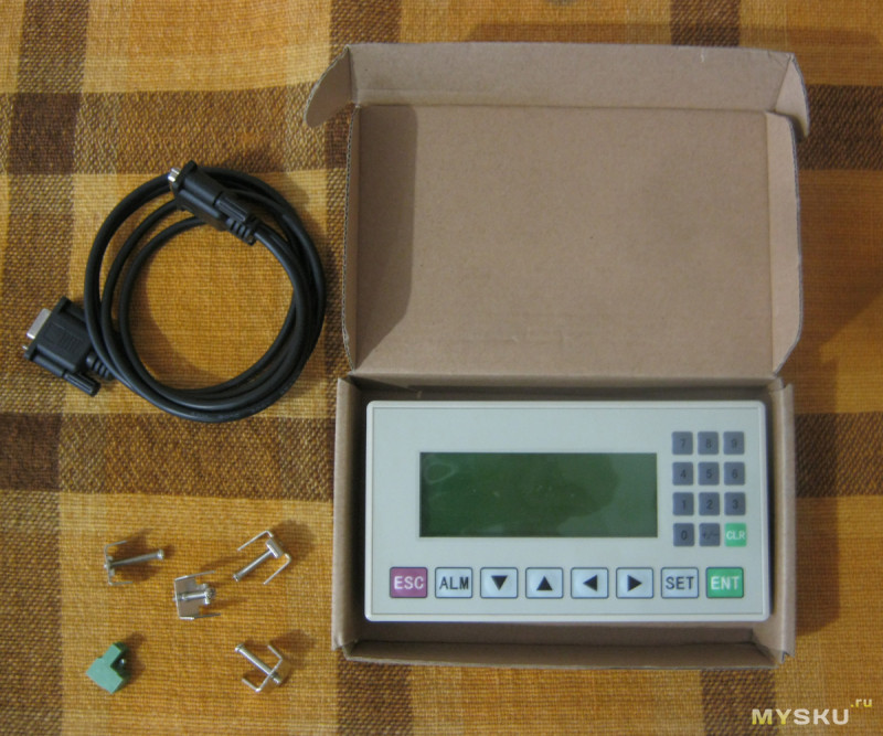
Комплект поставки
- HMI OP320-A-S
- Кабель RS232 для подключения к COM-порту компьютера, используется для программирования
- Клеммный разъем питания 24 В
- 4 металлических фиксатора для размещения HMI в щите шкафа
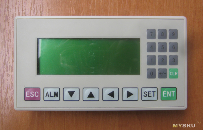
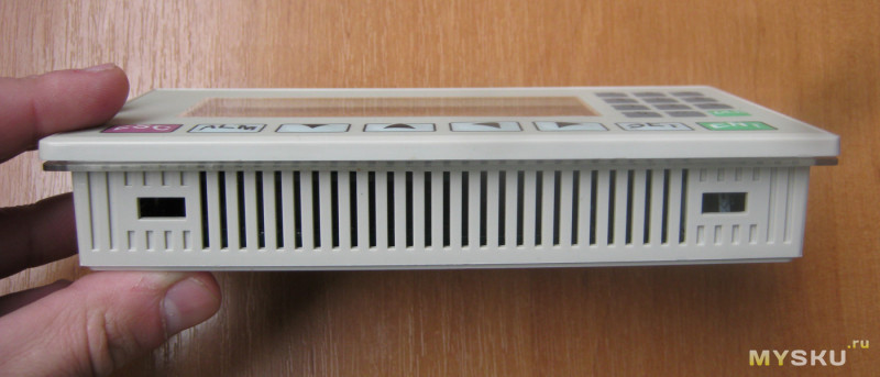
Спереди расположен достаточно большой 4.3» монохромный черно-зеленый дисплей и 20 кнопок управления
Сзади есть наклейка с названием модели и производителя TextView
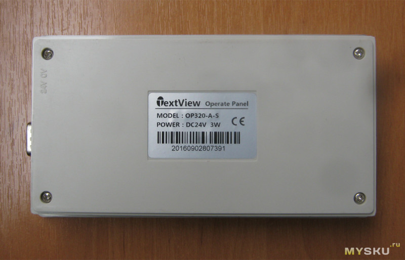
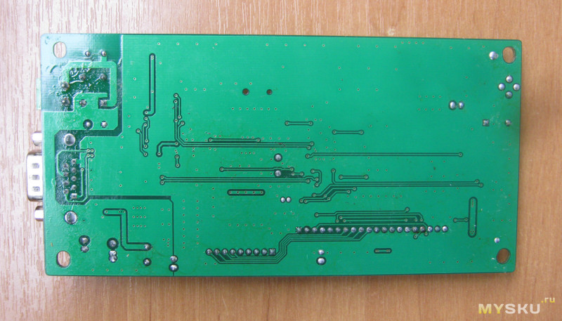
Универсальный порт связи RS232/485 выполнен в виде DB9M. Одновременно может работать только один из интерфейсов. Питание 24В подключается через 2-контактный зеленый разъем
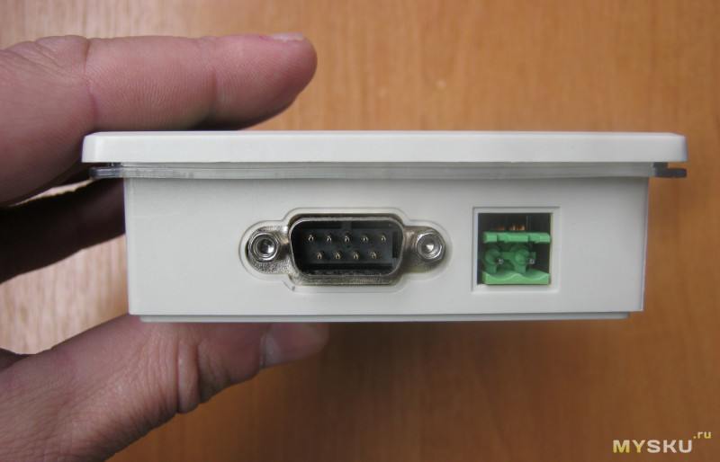
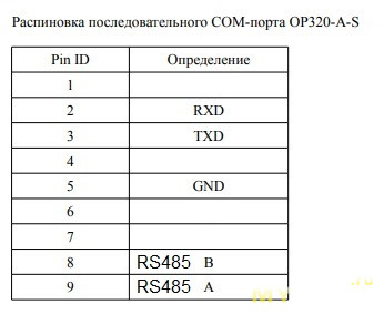
Распайку кабелей для подключения панели к различным моделям ПЛК смотрите в документе «Панель оператора OP320A / 320A-S. Руководство по эксплуатации» стр. 44-53.
На нижней стороне корпуса есть отверстия для вентиляции. Также на нижней и верхней сторонах корпуса располагаются по два узких отверстия для фиксации HMI на щите шкафа c помощью комплектных фиксаторов
HMI состоит из двух плат
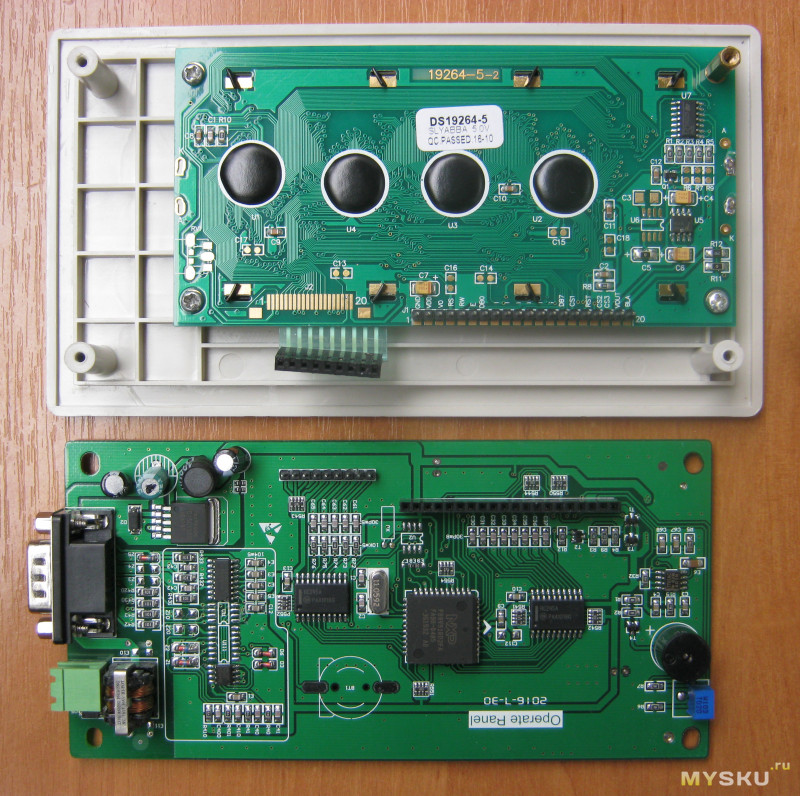
Мозгом девайса является микропроцессор NXP P89V51RD2FA с архитектурой 8051. Такие процессоры были популярны в начале 2000-х, пока их не вытеснили AVR. Процессор работает на частоте 11.0592 МГц [update1: во избежание возникших разночтений, имеется ввиду тактовая частота ], именно такая частота обеспечивает для 8051 корректную работу последовательной связи
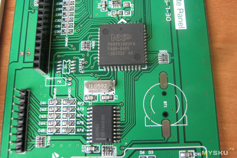
На обратной стороне процессорной платы нет элементов, флюс местами не отмыт
Модбас рулит
HMI OP320-A-S управляет контроллерами по интерфейсам RS232 и RS485. «Интерфейс» в данном случае это электрический стандарт передачи данных. Электросигналы при передаче данных между устройствами на программном уровне расшифровываются с помощью протоколов связи. OP320-A-S поддерживает 37 протоколов связи, в том числе самый популярный и универсальный Modbus.
Иногда путают понятие «интерфейс» и «протокол». Для понимания на бытовом уровне разницы между интерфейсом и протоколом, можно привести аналогию с людьми: у всех людей есть одинаковый интерфейс передачи данных- голосовые связки. Но протоколов связи больше одного: русский, шведский и другие языки. Поэтому два человека с одинаковым интерфейсом, но разными протоколами передачи данных не могут понимать друг друга. Модбас это международный язык общения в мире промышленной автоматики, как какой-нибудь попсовый английский в мире людей. Заранее прошу прощения у мэтров за изложение основ, но вдруг кто не знает.
Большинство ПЛК поддерживает протокол Modbus, а потому OP320-A-S можно к ним подключить. Кроме Modbus, OP320-A-S поддерживает протоколы Митсубиси, Сименс и других ПЛК. Впрочем, некоторые протоколы панель поддерживает не полностью, а лишь частично. Например, по протоколу Modbus панель может иметь доступ ко всем регистрам ПЛК Delta DVP. А при работе по протоколу Delta, панель будет иметь доступ только к малой части регистров.
Программирование
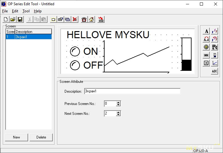
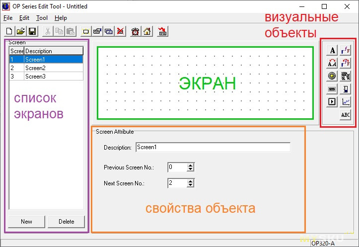
Для программирования OP320-A-S используется ПО OP20 Series Edit Tool (далее просто OP20 Tool)
OP320-A-S разных годов имеют разные прошивки и для их программирования используются разные версии OP20 Tool. Перепрошить панель новой прошивкой нельзя.
Например, мой девайс, который я покупал 3 года назад, программируется версией 6.5. А сейчас по тому же адресу продается панель, которая программируется OP20 Tool v8.0
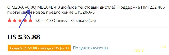
Поэтому при покупке нужно быть бдительным и обращать внимание на версию ПО, которое используется для программирования.
Впрочем, функционал у OP20 Tool версий 6.5 и 8.0 абсолютно одинаков.
Оригинальный OP20 Tool не поддерживает русский язык и поэтому текст на экран можно выводить только латиницей. Но есть лайфхак, как открыть поддержку русского языка. Нужно в в папке установленной программы OP20 Tool найти каталог «En» и переименовать его в «Ru», там же открыть блокнотом файл Language.ini и заменить строку «Version=En» на «Version=RU». Тогда можно будет использовать русские тексты на экране.
Программирование панели очень простое и сводится к тому, что на экране проекта размещаются визуальные объекты(числовые и битовые индикаторы, кнопки и др.) и настраиваются на адреса регистров ПЛК. Кроме адреса, у объектов есть некоторые другие свойства.
Принцип работы рассмотрим на примере двух основных объектов, битового и числового индикаторов.
Битовый индикатор
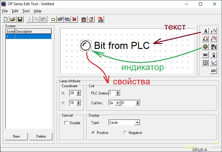
Этот объект отображает состояние битового регистра ПЛК в виде лампочки. У него совсем немного свойств:
- PLC Station, адрес ПЛК в сети
- Coil No, адрес битового регистра
- Coordinate, координаты местоположения
- Double, двойной размер
- Type, тип индикатора: круг или квадрат
- Positive, лампочка горит при значении регистра = 1
- Negative, лампочка горит при значении регистра = 0
У числового индикатора свойств по-больше, но не сильно
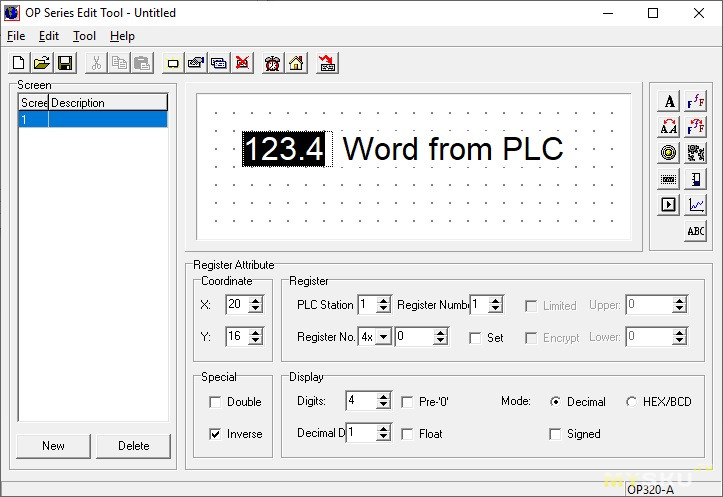
- Свойства PLC Station, Coordinate, Double идентичны предыдущему
- Register Numb, кол-во считываемых регистров(word): 1 для int, 2 для float
- Inverse, черный фон индикатора
- Digits, общее кол-во знаков (в том числе после запятой)
- Decimal D, кол-во знаков после запятой
- Pre -0, забить отсутствующие знакоместа числа нулями, напр. «001» вместо «1»
- Decimal, регистр отображается как десятичное беззнаковое число(unsigned)
- Signed, регистр отображается как десятичное число со знаком
- HEX/BCD, регистр отображается как шестнадцатеричное число
- Float, регистр отображается как число с плавающей точкой
- Set, разрешено изменение числа
- Limited, число можно изменять в границах от Lower до Upper
Как видим, ничего сложного. Остальные объекты тоже простые, как валенок. Научиться программировать OP320-A-S можно методом тыка, даже не читая мануалов. Но такая простота имеет и оборотную сторону медали: из-за малого количества визуальных объектов и их свойств, а так же из-за отсутствия скриптов программирования, получится построить только простую визуализацию.
В качестве примера работы, подключим панель к Ардуине (схема соединений и демонстрация работы на 5:07)
Обязательно скажут, что намного дешевле сделать для Ардуино экран с помощью 1602a и желудей. Да, профильным применением OP320-A-S является работа прежде всего с ПЛК и частотными преобразователями. В этом качестве панель показала себя надежным девайсом, работающим многие годы в заводских условиях.
Оригинальное видео продавца про работу OP320-A-S с китайским клоном ПЛК Митсубиси
На отечественном рынке OP320-A-S также продается под маркой ОВЕН как ИП320.
Достоинства и недостатки OP320-A-S
-одновременно может работать только один из интерфейсов: RS232 или RS485
-нет скриптов программирования
-малое количество объектов и их свойств
-в ПО нет эмулятора работы панели
-нельзя обновить прошивку
-под каждую прошивку своя версия ПО
+Modbus и другие протоколы передачи данных
+простота программирования
+много кнопок
+надежность
+баснословно низкая цена
Вот такой девайс. Надеюсь, было интересно.
10.04.2018 — Новые блоки питания Delta Electronics
Новые источники питания с креплением на ДИН-рейку: модель DRP-24V48W1AZ из популярной серии DRP и модель DRS-24V50W1NZ в популярном на рынке ультра компактном конструктиве.
Блоки питания DRP-24V48W1AZ (выходной ток 2 А, напряжение 24 VDC, мощность 48 Вт) подходят для всех применений, где требуется компактность и качество питания, и могут служить альтернативой источнику питания DVPPS02.
20.02.2018 — Преобразователи частоты Delta Electronics новой серии MS300 стали доступны со склада в Москве и Санкт-Петербурге!
Мощность от 0.2 до 22 кВт, предельно компактная конструкция преобразователя частоты, удобство монтажа и настройки, группировка параметров по применениям, пружинные клеммы, поддержка различных типов двигателей, 4 независимых наборов параметров для асинхронных двигателей, улучшенная функция торможения, преодоление кратковременных провалов напряжения, наличие импульсного входа для задания частоты, встроенный ПЛК, выносной пульт управления, перегрузочная способность 150% номинального тока в течение 60 сек или 200% в течение 3 сек, встроенный RS-485 и порт USB – это не полный список преимуществ новых частотных преобразователей серии MS300.
21.12.2017 — Delta Electronics признана лучшим Тайваньским брендом седьмой год подряд

Седьмой год подряд Delta Electronics входит в 20 лучших глобальных тайваньских брендов по результатам престижного исследования Best Taiwan Global Brands* со стоимостью бренда выросшей в 2017 году на 11% и достигшей цифры 250 млн. долларов США. Delta является единственной тайваньской маркой, которая показывает 2-х значный темп роста своей стоимости 5й год подряд, что является одним из самых высоких показателей.
подробнее…
14.12.2017 — новые модификации ПЛК DVP
В номенклатуру программируемых логических контроллеров Delta Electronics добавились новые модели с увеличенным количеством входов/выходов:
- DVP28SS211R
- DVP28SS211T 16 дискретных входов и 12 дискретных выходов (релейные или транзисторные соответственно)
- DVP28SA211R
- DVP28SA211T 16 дискретных входов и 12 дискретных выходов (релейные или транзисторные соответственно)
- DVP26SE11R
- DVP26SE11T 14 дискретных входов и 12 дискретных выходов (релейные или транзисторные соответственно)
04.12.2017 — Расширение номенклатуры ЧПУ
- Система ЧПУ для токарных станков: модель NC200P-LI-A с экраном 8” и ручным генератором импульсов (штурвал)
- Системы ЧПУ для обрабатывающих центров и фрезерно–сверлильно–расточных и др. станков: модель NC300A-MI-AE с экраном 8” и встроенным станочным пультом и модель NC300A-MS-AE с экраном 8” и отдельным станочным пультом
Компактные системы ЧПУ моделей NC30 и NC50, которые представляют собой полнофункциональный контроллер ЧПУ с поддержкой подключения внешнего монитора и клавиатуры.
- Компактное исполнение
- Подключение клавиатуры и станочного пульта по USB
- Подключение дисплея через VGA (разрешение минимум 1024*768)
- Вх/Вых по интерфейсу, G-кода стандарта ISO
- Шина DMCnet для сервоприводов, Ethernet, RS485
- USB host, карта памяти CF
Панели оператора
Аксессуары / DOP-A Series / DOP-AE Series / DOP-AS Series / DOP-B Series / TP02 Series / TP04G-AS1/TP04G-AS2 Series / TP04G-AL-C/TP04G-AL2 Series / TP05 / TP08 Series /
 Многофункциональные операторские панели или пульты — это специализированные устройства для оперативного ввода и отображения информации, которые могут осуществлять обмен данными с удаленным компьютером или контроллером через последовательный порт. В качестве устройства ввода применяется небольшая клавиатура или сенсорный экран, а для визуализации используются символьные или графические индикаторы. Обмен данными осуществляется по последовательным интерфейсным каналам RS-232/RS-485, что позволяет использовать терминалы на значительном удалении от контроллера.
Часто при построении распределенной системы управления возникает задача вводить и контролировать данные о технологическом процессе в самых разнообразных точках системы. Применение полноценного компьютера и монитора не всегда бывает экономически и технологически оправдано для этих целей. Обычно вполне достаточно компактного устройства с небольшим экраном и клавиатурой, обеспечивающего связь оператора с компьютером верхнего уровня.
Такой операторский пульт можно подключать к любой удаленной точке системы сбора данных и управления, с его помощью удобно контролировать основные параметры технологического процесса, производить задание начальных параметров и вносить необходимые изменения в ходе процесса.
Наша компания поставляет следующие операторские панели:
Модельный ряд панелей оператора DOP. Delta’s DOP series product lines include:
Optional Accessories
Модельный ряд текстовых панелей TP. Delta’s TP series product lines include :
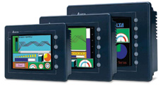
Операторская панель серии DOP

Панели новой серии DOP-A/AE предназначены для визуализации информации, поступающей от микропроцессорных устройств, и управления производственными и технологическими процессами. Использование операторских панелей в системах управления позволяет создать удобный человеко-машинный интерфейс (Human Machine Interface) — централизованное рабочее место человека-оператора, управляющего машиной.
Панели позволяют отображать текстовую, в том числе на русском языке, и графическую информацию: текущие и аварийные сообщения, технологические параметры, графики и диаграммы. При помощи панелей можно осуществлять управление технологическим процессом, а также изменять параметры настройки системы и сохранять данные. Управление процессом удобно организовать в виде системы меню. Панели подключаются к устройствам через последовательные каналы обмена. Настройка панелей производится с использованием специального программного обеспечения — пакета SCRedit, работающего в среде Widows 98/NT/2000/XP. Сохранение и перенос данных и параметров настройки возможен также при помощи SMC (Smart Media Card) карт.
Модернизированная (относительно DOP-A) серия операторских панелей DOP- AE отличается:
- увеличенной до 512кБ SRAM памятью;
- 8 и 10.4 дюймовые панели поддерживают 65536 цветов;
- совместно с принтерной картой поддерживают прямую печать на принтере;
- имеют USB порт для чтения данных и подключения принтера.
Особенности:
- Используют большое количество драйверов для обмена данными по последовательному каналу с различными устройствами: программируемыми логическими контроллерами (ПЛК), вспомогательными и температурными контроллерами, преобразователями частоты более чем 20 ведущих производителей, включая всю продукцию DELTA, а также Omron, Siemens, Mitsubishi и др.
- Обеспечивают ввод макрокоманд при выполнении сложных операций. Используют специальные макрокоманды обмена для написания протоколов связи по последовательному каналу с уникальным оборудованием.
- Минимизировано время обмена данными с оборудованием за счет применения порта USB 1.1
- Удобный редактор меню с возможностью загрузки одновременно нескольких меню в память HMI.
- 2 последовательных порта обмена, использующих различные протоколы. Возможность подключения и работы с двумя одинаковыми или различными устройствами одновременно.
- Возможность подключения нескольких ПЛК c протоколом RS-485 при использовании порта COM2.
- Возможность симуляции работы в режимах On-line/Off-line.
- Используют SMC (Smart Media Card) плату для записи, сохранения, загрузки и переноса данных.
- Возможность установки пароля для защиты интеллектуальной собственности.
- Выбор приоритета пользователей для доступа к отдельным параметрам.
- Для ввода и отображения данных применяются сенсорный экран и вспомогательная клавиатура.
- Самый высокий показатель цена-качество в своём классе.
Спецификация:
|
Модель |
DOP-A57GSTD |
DOP-A57CSTD |
DOP-A75CSTD |
DOP-A10TCTD |
|
Операционная система |
Windows Base Real Time OS |
|||
|
Тип микроконтроллера |
32-bit RISC / 202.8MHz |
|||
|
Память прикладных программ ROM |
NOR Flash ROM 4 Mbytes (System: 1MB / User: 3MB — приблизительно 960 экранов при 3,2 KB на экран) |
|||
|
Память обмена данными SDRAM |
16Mbytes |
32Mbytes |
||
|
Системная память (SRAM) |
256Kbytes (использует литиевую батарею) |
|||
|
Внешняя карта памяти |
Smart Media Card (Windows®98/Me/2000/XP FAT Compatible) |
|||
|
USB порт |
1 CLIENT Ver 1.1 |
|||
|
Последовательные порты (UART) |
COM1: RS-232C ; COM2: RS-232C/422/485 |
|||
|
Дисплей |
Тип — 5.7”FSTN LCD (16 градаций серого) 320 x 240 pixels CCFL подсветка |
Тип — 5.7”Color STN LCD (256 цветов) 320 x 240 pixels CCFL подсветка |
Тип — 7.5”Color STN LCD (256 цветов) 640 x 480 pixels 2хCCFL подсветка |
Тип — 10.4”Color TFT LCD (256 цветов) 640 x 480 pixels 2хCCFL подсветка |
|
Вспомогательная панель |
Определяемые пользователем 4 кнопки |
Определяемые пользователем 5 кнопок |
Определяемые пользователем 6 кнопок |
|
|
Сенсорная панель, размер |
6.4” |
8.2” |
11.0” |
|
|
Счетчик реального времени RTC |
Встроенный |
|||
|
Тип литиевой батареи |
CR2032 x 1 |
|||
|
Зуммер |
85dB |
|||
|
Напряжение питания/Потребление макс. |
+24В (-10%…+20%)/ 7.2 Вт |
+24В (-10%…+20%)/10 Вт |
+24В (-10%…+20%)/15 Вт |
|
|
Охлаждение |
Естественное воздушное охлаждение |
|||
|
Корпус |
Соответствует NEMA4 (использование внутри помещений) |
|||
|
Рабочая температура |
0…50°С |
|||
|
Температура хранения |
-20…+60°С |
|||
|
Влажность среды |
10%…90%, без конденсата |
|||
|
Габаритные размеры (Д) x (В) x (Ш) мм |
184.1 x 144.1 x 46.9 |
243.1 x 178.1 x 47 |
297.1 x 222 x 51.1 |
|
|
Масса |
650 г |
950 г |
1420 г |
Модернизированная (относительно DOP-A) серия операторских панелей DOP-AE компании DELTA ELECTRONICS отличается:
- увеличенной до 512кБ SRAM памятью;
- 8 и 10.4 дюймовые панели поддерживают 65536 цветов;
- совместно с принтерной картой поддерживают прямую печать на принтере;
- имеют USB порт для чтения данных и подключения принтера.
Цена (Price List) Выбрать панель оператора =>
Вернуться назад
Телефон
: +7 (495) 984-51-05 (Москва), +7 (812) 640-46-90 (Санкт-Петербург), E-mail:
info@delta-mail.ru, Время работы:
с 9.00 до 18.00 (без обеда).
ENGLISH
ORTHOPANTOMOGRAPH® OP300
3D Dental X-Ray System
User Manual
210457 rev. 7
ORTHOPANTOMOGRAPH® OP300
|
Copyright |
Code: 210457 rev 7 Date: July 7, 2014 |
|
|
Copyright © 7/7/14 by Instrumentarium Dental, PaloDEx |
||
|
Group Oy. |
||
|
All rights reserved. |
||
|
ORTHOPANTOMOGRAPH®/ |
INSTRUMENTARIUM |
DENTAL™/ CLINIVIEW™ is a registered trademark/ a common law trademark of Instrumentarium Dental,
PaloDEx Group Oy.
U.S. patents US6731717, US6829326 and USRE41197.
Finnish patents 114383.
Documentation, trademark and the software are copyrighted with all rights reserved. Under the copyright laws the documentation may not be copied, photocopied, reproduced, translated, or reduced to any electronic medium or machine readable form in whole or part, without the prior written permission of Instrumentarium Dental.
The original language of this manual is English.
Instrumentarium Dental reserves the right to make changes in specification and features shown herein, or discontinue the product described at any time without notice or obligation. Contact your Instrumentarium Dental representative for the most current information.
|
Manufacturer |
Instrumentarium Dental, PaloDEx Group Oy |
|
Nahkelantie 160 (P.O. Box 20) |
|
|
FI-04300 Tuusula |
|
|
FINLAND |
|
|
Tel. +358 10 270 2000 |
|
|
Fax. +358 10 270 2230 |
|
|
For service, contact your local distributor. |

ORTHOPANTOMOGRAPH® OP300

Table of Contents
|
1 Introduction…………………………………………………………………………………………………… |
1 |
|
|
1.1 |
ORTHOPANTOMOGRAPH® OP300 ………………………………………………………….. |
1 |
|
1.2 |
References……………………………………………………………………………………………… |
2 |
|
1.3 |
Intended use …………………………………………………………………………………………… |
2 |
|
1.4 |
Associated documentation ………………………………………………………………………… |
3 |
|
1.5 |
Abbreviations used in this manual ……………………………………………………………… |
3 |
|
1.6 |
Warnings and precautions ………………………………………………………………………… |
3 |
|
1.6.1 Warnings to be observed during use ………………………………………………… |
3 |
|
|
1.6.2 Warnings for cross infection…………………………………………………………….. |
5 |
|
|
1.6.3 General warnings…………………………………………………………………………… |
5 |
|
|
1.7 |
Disclaimer ………………………………………………………………………………………………. |
8 |
|
1.8 |
Disposal …………………………………………………………………………………………………. |
8 |
|
2 Unit description …………………………………………………………………………………………….. |
9 |
|
|
2.1 |
Main parts and controls…………………………………………………………………………….. |
9 |
|
2.2 |
Patient positioning lights …………………………………………………………………………. |
11 |
|
2.3 |
Patient positioning panel …………………………………………………………………………. |
14 |
|
2.3.1 Cephalometric unit (optional) …………………………………………………………. |
14 |
|
|
2.4 |
Emergency stop switch …………………………………………………………………………… |
15 |
|
3 Imaging programs ……………………………………………………………………………………….. |
17 |
|
|
3.1 |
Panoramic programs………………………………………………………………………………. |
17 |
|
3.2 |
Cephalometric programs…………………………………………………………………………. |
23 |
|
3.3 |
3D SFOV programs………………………………………………………………………………… |
25 |
|
3.4 |
3D MFOV (Maxio) programs ……………………………………………………………………. |
26 |
|
3.5 |
Selecting resolution and FOV ………………………………………………………………….. |
28 |
|
3.6 |
MAR, Metal Artifact Reduction …………………………………………………………………. |
29 |
|
3.7 |
Exposure settings for 3D imaging …………………………………………………………….. |
30 |
|
4 Touch screen display…………………………………………………………………………………… |
33 |
|
|
4.1 |
Main control panel………………………………………………………………………………….. |
33 |
|
4.2 |
Modality section …………………………………………………………………………………….. |
34 |
|
4.2.1 Exposure indicators and settings ……………………………………………………. |
34 |
|
|
4.3 |
Automatic dose control (ADC)………………………………………………………………….. |
35 |
|
4.4 |
Status section………………………………………………………………………………………… |
36 |
|
4.5 |
Other sections ……………………………………………………………………………………….. |
36 |
|
5 Using the unit………………………………………………………………………………………………. |
39 |
||
|
5.1 |
Attaching and removing the sensor…………………………………………………………… |
39 |
|
|
5.1.1 |
Attaching the sensor …………………………………………………………………….. |
39 |
|
|
5.1.2 |
Removing the sensor ……………………………………………………………………. |
40 |
|
|
5.2 |
Preparing the system ……………………………………………………………………………… |
40 |
|
|
5.3 |
Panoramic exposures …………………………………………………………………………….. |
41 |
|
|
5.3.1 |
Positioning devices ………………………………………………………………………. |
41 |
|
|
5.3.2 |
Sectional imaging…………………………………………………………………………. |
42 |
|
|
5.3.3 |
General instructions ……………………………………………………………………… |
42 |
|
|
5.3.4 |
Default exposure settings……………………………………………………………… |
43 |
|
|
5.3.5 User Configurable Default Program ………………………………………………… |
44 |

|
5.3.6 |
Patient positioning………………………………………………………………………… |
44 |
|||
|
5.3.6.1 |
Panoramic exposure………………………………………………………… |
44 |
|||
|
5.3.6.2 |
TMJ exposure…………………………………………………………………. |
48 |
|||
|
5.3.6.3 |
Maxillary Sinus exposure………………………………………………….. |
51 |
|||
|
5.3.7 |
Taking the exposure……………………………………………………………………… |
53 |
|||
|
5.3.8 |
Multilayer Selection ………………………………………………………………………. |
54 |
|||
|
5.4 |
Cephalometric exposures ……………………………………………………………………….. |
56 |
|||
|
5.4.1 |
General instructions ……………………………………………………………………… |
56 |
|||
|
5.4.2 |
Patient positioning………………………………………………………………………… |
58 |
|||
|
5.4.2.1 Pediatric lateral and Lateral projection ……………………………….. |
58 |
||||
|
5.4.2.2 |
PA projection ………………………………………………………………….. |
60 |
|||
|
5.4.2.3 |
Reverse towne projection …………………………………………………. |
61 |
|||
|
5.4.2.4 |
Waters view ……………………………………………………………………. |
62 |
|||
|
5.4.2.5 Carpus view (Not available in USA and Canada)…………………. |
63 |
||||
|
5.4.2.6 |
Taking the exposure ………………………………………………………… |
63 |
|||
|
5.5 |
3D exposures ………………………………………………………………………………………… |
64 |
|||
|
5.5.1 |
Positioning devices ………………………………………………………………………. |
64 |
|||
|
5.5.2 |
General instructions ……………………………………………………………………… |
64 |
|||
|
5.5.3 |
Patient positioning………………………………………………………………………… |
66 |
|||
|
5.5.4 |
Scout image ………………………………………………………………………………… |
70 |
|||
|
5.5.5 |
3D image…………………………………………………………………………………….. |
71 |
|||
|
5.5.5.1 Stone model and radiographic guide scan ………………………….. |
72 |
||||
|
5.6 |
Warnings and error messages …………………………………………………………………. |
73 |
|||
|
5.6.1 |
Acknowledging errors……………………………………………………………………. |
73 |
|||
|
5.6.2 |
Image transfer errors…………………………………………………………………….. |
73 |
|||
|
6 |
Troubleshooting ………………………………………………………………………………………….. |
75 |
|||
|
6.1 |
Patient positioning………………………………………………………………………………….. |
75 |
|||
|
6.2 |
Image appearance …………………………………………………………………………………. |
78 |
|||
|
6.3 |
Artefacts ……………………………………………………………………………………………….. |
79 |
|||
|
6.4 |
Unit operation………………………………………………………………………………………… |
81 |
|||
|
7 |
Maintenance………………………………………………………………………………………………… |
83 |
|||
|
7.1 |
Maintenance procedure …………………………………………………………………………. |
83 |
|||
|
7.1.1 |
Annual maintenance …………………………………………………………………….. |
83 |
|||
|
7.1.2 |
Calibration intervals………………………………………………………………………. |
83 |
|||
|
7.2 |
Changing the fuses ………………………………………………………………………………… |
84 |
|||
|
7.3 |
Cleaning and decontaminating the unit……………………………………………………… |
84 |
|||
|
8 |
Calibration and adjustment ………………………………………………………………………….. |
87 |
|||
|
8.1 |
Introduction …………………………………………………………………………………………… |
87 |
|||
|
8.2 |
Preparing for calibration ………………………………………………………………………….. |
88 |
|||
|
8.3 |
Panoramic calibration……………………………………………………………………………… |
89 |
|||
|
8.3.1 |
Panoramic geometry calibration……………………………………………………… |
89 |
|||
|
8.3.2 |
Panoramic pixel calibration ……………………………………………………………. |
90 |
|||
|
8.3.3 Panoramic Quality Check (optional)………………………………………………… |
91 |
||||
|
8.4 |
3D calibration ………………………………………………………………………………………… |
93 |
|||
|
8.4.1 |
3D geometry calibration ………………………………………………………………… |
93 |
|||
|
8.4.2 |
3D pixel calibration……………………………………………………………………….. |
93 |
|||
|
8.4.3 3D Quality Check program…………………………………………………………….. |
95 |
||||
|
8.5 |
Cephalometric calibration………………………………………………………………………… |
96 |

|
8.5.1 Ceph pixel calibration……………………………………………………………………. |
96 |
||
|
8.5.2 Ceph Quality check program (Optional)…………………………………………… |
96 |
||
|
9 |
Technical data……………………………………………………………………………………………… |
99 |
|
|
9.1 |
Technical specifications ………………………………………………………………………….. |
99 |
|
|
9.2 |
Unit dimensions……………………………………………………………………………………. |
109 |
|
|
9.3 |
Symbols that appear in the unit………………………………………………………………. |
111 |
|
|
9.4 |
Labels on the unit…………………………………………………………………………………. |
113 |
|
|
9.5 |
Electromagnetic Compatibility (EMC) tables…………………………………………….. |
114 |
|
|
9.6 |
X-ray tube assemblies…………………………………………………………………………… |
119 |
|
|
10 |
PC requirements………………………………………………………………………………………… |
121 |
|
|
10.1 |
Minimum PC requirements…………………………………………………………………….. |
121 |
|
|
10.2 |
The dental imaging software ………………………………………………………………….. |
124 |


1Introduction
1.1ORTHOPANTOMOGRAPH® OP300
INSTRUMENTARIUM DENTAL™ ORTHOPANTOMOGRAPH® OP300 x-ray unit (hereafter called “OP300”) is a dental x-ray system for producing high quality digital images of dentition, TM-joints and skull. In order to take images with OP300 you need a suitable PC hardware connected to the OP300 unit and CLINIVIEW™ software (or suitable third party software via TWAIN driver) to capture and manage images.
OP300 performs the following procedures:
Panoramic
•Standard panoramic
•Pediatric panoramic
•Wide arch panoramic
•Bitewing
•TMJ, PA projection
•Ortho TMJ, axial corrected lateral projection
•Maxillary sinus
•Ortho Zone enhanced panoramic
•Orthogonal panoramic
Cephalometric (optional)
•Cephalometric lateral projection
•Cephalometric pediatric lateral projection
•Cephalometric postero-anterior (PA) projection
•Reverse Towne projection
•Waters view
•Carpus program (optional) (Not available in USA and Canada)
|
210457 rev 7 |
Instrumentarium Dental |
1 |

1 Introduction
3D SFOV (optional) H x W
•61×41 mm Field of View
•61×78 mm Field of View
3D MFOV (Maxio) (optional) H x W
•MFOV (Maxio) 50 x 50 mm Field of View
•MFOV (Maxio) 61 x 78 mm Field of View
•MFOV (Maxio) 78 x 78 mm Field of View
•MFOV (Maxio) 78 x 150 mm Field of View
•MFOV (Maxio) 130 x 150 mm Field of View (optional)
1.2References
The following instructions are delivered with in the
OP300 installation manual:
•Firmware update instructions
•Calibration instructions
•Cephalostat upgrade instructions
•Cephalostat side changing instructions
The following instructions are separate and can be ordered from customer service:
•3D upgrade instructions are delivered with the 3D upgrade kit.
1.3Intended use
OP300 must only be used and operated by healthcare professionals and other qualified professionals. OP300 must only be used to take panoramic, cephalometric and
3D images of the dento-maxillofacial complex of the human skull. It must not be used to take images of any other part of the human body.
Panoramic and 3D exposures should not be used if conventional intraoral radiographic images (like bitewing exposures) would be sufficient.
Cone beam computed tomography images are not adequate for the analysis of soft tissue.
|
2 |
Instrumentarium Dental |
210457 rev 7 |
![]()
1 Introduction
CAUTION! USA only: Federal law restricts this device to sale by or on the order of a dentist or other qualified professional.
1.4Associated documentation
•OP300 user manual
•OP300 installation manual
•The CLINIVIEW™ software user manual
•The CLINIVIEW™ software installation manual
•The user manual supplied with the dental imaging software
•The installation manual supplied with the dental imaging software
•The user manual supplied with the 3D imaging software
•The installation manual supplied with the 3D imaging software
1.5Abbreviations used in this manual
FOV = Field Of View. The cylindrical 3D volume that is reconstructed by the system.
ROI = Region Of Interest. The anatomical area or region of the patient that you are interested to examine.
FH = Frankfort-Horizontal
H = Horizontal
1.6 Warnings and precautions
1.6.1Warnings to be observed during use
The unit may be dangerous to the user and the patient, if the safety regulations in this manual are ignored, if the unit is not used in the way described in this manual and/or if the user does not know how to use the unit.
The unit must only be used to take the dental x-ray exposures described in this manual. The unit must NOT be used to take any other x-ray exposures. It is not safe to use the unit to take x-ray exposures, that it is not designed for.
|
210457 rev 7 |
Instrumentarium Dental |
3 |

1 Introduction
Only professionally qualified dental and/or medical personnel are allowed to operate the unit and carry out any diagnoses based on output from the unit.
Because the x-ray limitations and safety regulations change from time to time, it is the responsibility of the user to make sure that all the valid safety regulations are fulfilled.
When taking an x-ray exposure of a patient with exceptional anatomy (typically very tall or large) use the Test-mode (no x-rays) first to make sure that patient can be positioned correctly to the unit and for checking that the unit doesn’t hit the patient.
Operator should maintain visible contact with the patient and technique factors. This allows immediate termination of radiation by the release of the exposure button in the event of a malfunction or disturbance.
It is the responsibility of the doctor to decide whether x-ray exposure or any additional exposures are justified and necessary.
The minimum height of patient that can be x-rayed is 120 cm (3.9ft / 47.2in) and the maximum is 200 cm (6ft /78in). These heights only apply to patients with normal anatomy.
Always use the lowest suitable x-ray dose to obtain the desired level of image quality.
Avoid taking x-ray exposures of pregnant women.
When taking an x-ray exposure of a child always use the lowest possible x-ray dose, the smallest possible image area and the lowest possible resolution that allows you to perform the required diagnostic task.
If the patient is using a pacemaker, consult the manufacturer of the pacemaker before taking an exposure to confirm that the x-ray unit will not interfere with the operation of the pacemaker.
Decontaminate all the surfaces that the patient is in contact with after every patient to prevent cross infection.
Decontaminate all device accessories that contact the patient during a radiographic examination.
Do not open or remove any of the unit’s enclosures. No user serviceable parts inside.
|
4 |
Instrumentarium Dental |
210457 rev 7 |

1 Introduction
The customer must ensure that the siting environment fulfills the requirements listed in the Installation manual. Special attention must be paid to the strength of the floor and wall materials, electrical mains and radiation protection. It is the responsibility of the customer to ensure that the site is large enough for the patients.
The unit contains toxic materials that need to be handled properly when disposing the unit. Return the unit to the dealer in the end of its life cycle.
Excessive dust should be cleaned from the unit for free airflow and cooling. Switch of the unit before cleaning.
Always follow the instructions for patient positioning and imaging procedures instructed in the User Manual.
In case of water damage/water dropping over the product, call for service technician to ensure the product is fully operational according to specification.
1.6.2Warnings for cross infection
Always use available disposable protective covers with the patient positioning accessories:
•Bite fork cover
•Chin support cover
•Head support cover
•Nose support cover
•Ear holder cover
1.6.3General warnings
Personnel operating the device must be adequately trained with respect to the technological principles of operation and radiation protection when using cone beam computed tomography (CBCT) imaging.
This unit complies with the EMC (Electromagnetic
Compatibility) according to IEC 60601-1-2. Radio transmitting equipment, cellular phones etc. shall not be used in close proximity of the unit as they could influence the performance of the unit.
|
210457 rev 7 |
Instrumentarium Dental |
5 |

1 Introduction
The correct software and settings in the workstation are essential to the performance of the unit. Consult technical support to ensure correct setup.
Danger: Explosion hazard — do not use in the presence of flammable anesthetics, gases or vapors.
The unit is factory set to operate using a 230-240 ±10 VAC power supply. Never connect the unit to a power supply different to the voltage marked on the unit.
The site must fulfill the environmental requirements in the installation manual chapter technical specifications.
There should be free space around the unit for safe operation.
To maintain patient safety it is mandatory to use an unshielded CAT6 Ethernet cable between the unit and the network or workstation, so that multiple chassis are not connected. Non-medical grade PC should not be used in patient environment.
This product itself complies with IEC 60601-1 medical safety standard but in order to the system incorporating also a PC to comply the standard, EITHER the PC has to be a medical PC OR the PC has to be located over 1,5 meters apart from the unit. The installer and the user of the system shall confirm that at least one of the above requirements is fulfilled. A PC is a medical one if it complies IEC 60601-1 standard and that is indicated in the accompanying documents of the PC. See chapter Technical specifications, Minimum PC Requirements, in user manual.
The unit shall be connected directly to the acquisition PC with an Ethernet cable. Connection through the LANnetwork of the site is not allowed. Two network ports are needed in the PC in order to connect also to the site network.
All service operations must be made by authorized service personnel only.
The annual service as described in manual is mandatory for the correct and safe operation of the unit.
When taking exposures, operators and service personnel must protect themselves from radiation and remain at least two meters (six feet) away from the unit during exposure.
|
6 |
Instrumentarium Dental |
210457 rev 7 |

1 Introduction
Protect the patient from scattered radiation by placing a protective lead apron over the patient.
The unit must be installed and serviced according to the unit Installation & adjustments manual by a qualified technician.
Only personnel trained and approved by the manufacturer of the unit are allowed to service the unit. 3D should not be used for routine or screening examinations in which a radiograph is taken regardless of the presence or absence of clinical signs and symptoms. 3D imaging examinations must be justified for each patient to demonstrate that the benefits outweigh the risks.
Where it is likely that evaluation of soft tissues will be required as part of the patient’s radiological assessment, the imaging should be done using conventional medical CT or MR, rather than 3D imaging using Cone Beam technology.
Make sure that patient’s thyroid glands are protected by a lead apron during the exposure.
The place where the unit is to be installed and the position from where the user will take exposures must be correctly shielded from the radiation that is generated when the unit is operated. Ensure to fulfill or exceed the requirements of your local regulations.
The unit or its parts must not be changed or modified in any way without approval and instructions from the manufacturer.
When servicing use only approved replacement parts supplied by the manufacturer.
The use of accessories not complying with the equivalent safety requirements of this equipment may lead to a reduced level of safety of the resulting system.
If this device is used with 3rd party imaging application software not supplied by the manufacturer, the 3rd party imaging application software must comply with all local laws on patient information software. This includes the
Medical Device Directive 93/42/EEC and/or relevant legal requirements in the USA.
Do not connect any equipment to the unit that has not been supplied with the unit or that is not recommended by the manufacturer. The use of accessory equipment not complying with the equivalent safety requirements of this
|
210457 rev 7 |
Instrumentarium Dental |
7 |

1 Introduction
equipment may lead to a reduced level of safety of the resulting system.
All protective covers must be properly installed before handing unit to the user or when operating the unit. Correct sharp layer should be chosen when using multilayer PAN images. See user manual chapter
Multilayer PAN images for correct procedure.
1.7 Disclaimer
The manufacturer shall have no liability for consequential damages, personal injury, loss, damage or expense directly or indirectly arising from the use of its products. No agent, distributor or other party is authorized to make any warranty or other liability on behalf of the manufacturer with respect to its products.
1.8 Disposal
The device, its spare parts, its replacement parts and its accessories may include parts that are made of or include materials that are non-environmentally friendly or hazardous. These parts must be disposed of in accordance with all local, national and international regulations regarding the disposal of non-environmentally friendly or hazardous materials.
Unit has at least the following parts that should be regarded as non-environmental friendly waste products:
■Tubehead (Pb, oil)
■Collimator (Pb)
■All electronic circuits, electronic boards inside
■Sensor covers (EMC painted)
|
8 |
Instrumentarium Dental |
210457 rev 7 |

2Unit description
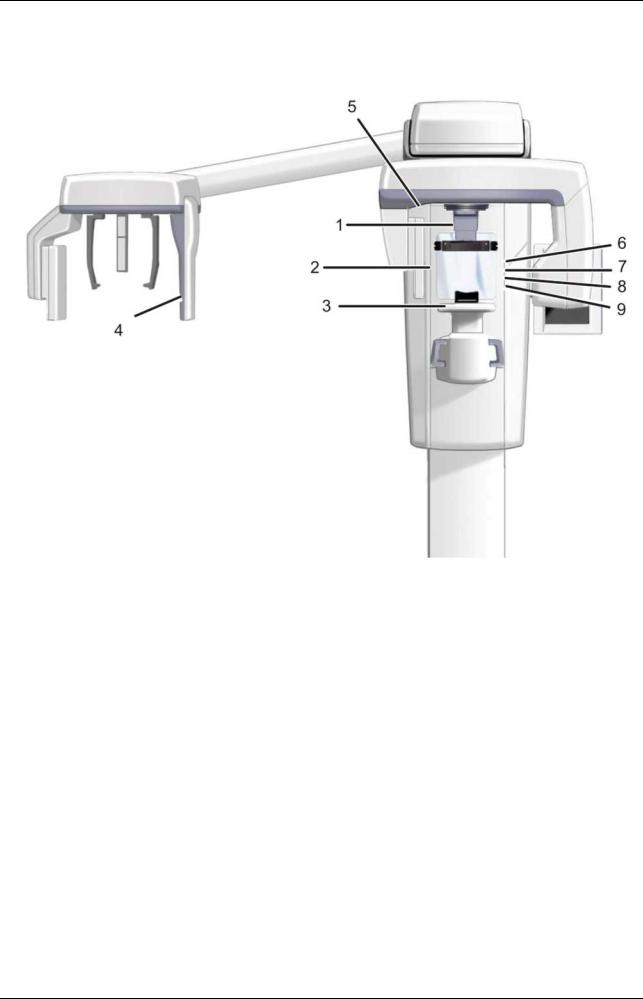
2.1Main parts and controls
1.Column
2.Carriage
3.Main support
4.Rotating unit
5.On/off switch (rear of carriage) and main fuses
6.Tubehead assembly
7.Touch screen display
8.Positioning panel
9.Sensor head
10.Head support 11.Chin rest 12.Handles 13.Cephalostat unit 14.Cephalostat sensor 15.Secondary collimator 16.Positioning panel
Fig 1.1. On/off switch and main fuses
PC with MDD approved dental imaging software and 3D viewing software (not included).
All software must conform to the MDD and the relevant legal requirements in the USA.
The PC must conform to all the unit and dental imaging software requirements.
|
210457 rev 7 |
Instrumentarium Dental |
9 |

2 Unit description
1.Sensor holder (units without 3D option)
2.Panoramic sensor
1.3D sensor (units with 3D option)
2.Panoramic sensor
|
10 |
Instrumentarium Dental |
210457 rev 7 |
2 Unit description
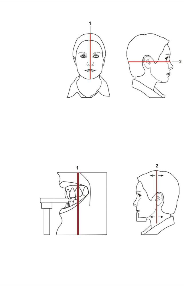
2.2 Patient positioning lights
1.Midsagittal light
2.Frankfort horizontal (FH) light /
Horizontal light, top of 130 mm high FOV (3D MFOV (Maxio) option only)
3.Image layer light
4.Cephalometric FH light
5.TMJ light
6.Horizontal light, top of 78 mm high FOV (3D MFOV (Maxio) option only)
7.Horizontal light, top of 61 mm high FOV (3D option only)
8.Horizontal light, top of 50 mm FOV (3D MFOV (Maxio) option only)
9.Horizontal light, bottom of FOV (3D option only)
|
210457 rev 7 |
Instrumentarium Dental |
11 |
2 Unit description
Panoramic lights
Fig 1.1.
1. Midsagittal light
2. FH light
Fig 1.2.
1. Image layer light
2. TMJ light
|
12 |
Instrumentarium Dental |
210457 rev 7 |
![]()
2 Unit description
Cephalometric lights
Fig 1.3.
1. FH light
3D lights (optional)
Note! Appropriate lasers are turned automatically on based on selected FOV.
Fig 1.4.
1.Midsagittal light
2.Horizontal light, top of FOV
Note! With 3D MFOV (Maxio) option height 130 mm is indicated with Frankfort horizontal (FH) light. Move FH light to 130 mm position (locked in up-position).
3.Horizontal light, bottom of FOV
|
210457 rev 7 |
Instrumentarium Dental |
13 |
2 Unit description
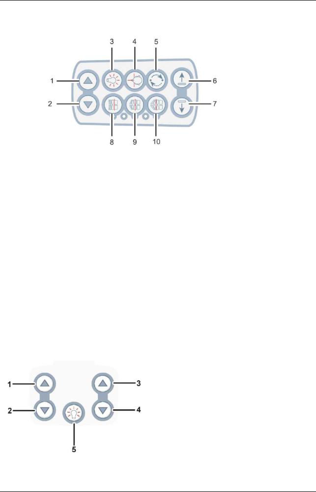
2.3 Patient positioning panel
Fig 1 5
1.Carriage UP
2.Carriage DOWN
3.Positioning lights ON/OFF
4.Patient positioning
5.Start positioning
6.Chin support UP
7.Chin support DOWN
8.Move the image layer anterior before exposure 3 mm, with sinus program 10 mm
9.Normal occlusion/ reset position
10.Move the image layer posterior before exposure 3 mm, with sinus program 10 mm
2.3.1Cephalometric unit (optional)
1.Carriage UP
2.Carriage DOWN
3.Carriage UP
4.Carriage DOWN
5.Positioning lights ON/OFF
|
14 |
Instrumentarium Dental |
210457 rev 7 |

2 Unit description
2.4 Emergency stop switch
In case of malfunction of the exposure button or other protective devices of the unit, an emergency stop switch is provided near the handles and on the roof of the cephalostat head so that the patient can reach it.
If the emergency stop switch is pressed during an exposure, the exposure is terminated immediately and the x-ray unit is completely stopped. An interrupted exposure cannot be continued later, but has to be retaken from the beginning.
Fig 1.6.
Fig 1.7.
Press to stop the unit, rotate to release.
|
210457 rev 7 |
Instrumentarium Dental |
15 |

2 Unit description
|
16 |
Instrumentarium Dental |
210457 rev 7 |

3Imaging programs
3.1Panoramic programs
Standard: Magnification 1.3
Exposure settings for panoramic program
|
100 VAC |
66 kV/5 mA |
66 kV/8 mA |
66 kV/10 mA |
70 kV/13 mA |
|
230 VAC |
66 kV/5 mA |
66 kV/8 mA |
66 kV/10 mA |
70 kV/13 mA |
|
< default > |
Pediatric: Magnification 1.3
Exposure settings for pediatric program
|
100 VAC |
66 kV/4 mA |
66 kV/6.3 mA |
66 kV/8 mA |
70 kV/10 mA |
|
230 VAC |
66 kV/4 mA |
66 kV/6.3 mA |
66 kV/8 mA |
70 kV/10 mA |
|
< default > |
|
210457 rev 7 |
Instrumentarium Dental |
17 |

3 Imaging programs
Pediatric patients can be imaged with less radiation dosage and shorter exposure time. Patients with jaw more narrow than average jaw can be exposed with this procedure too.
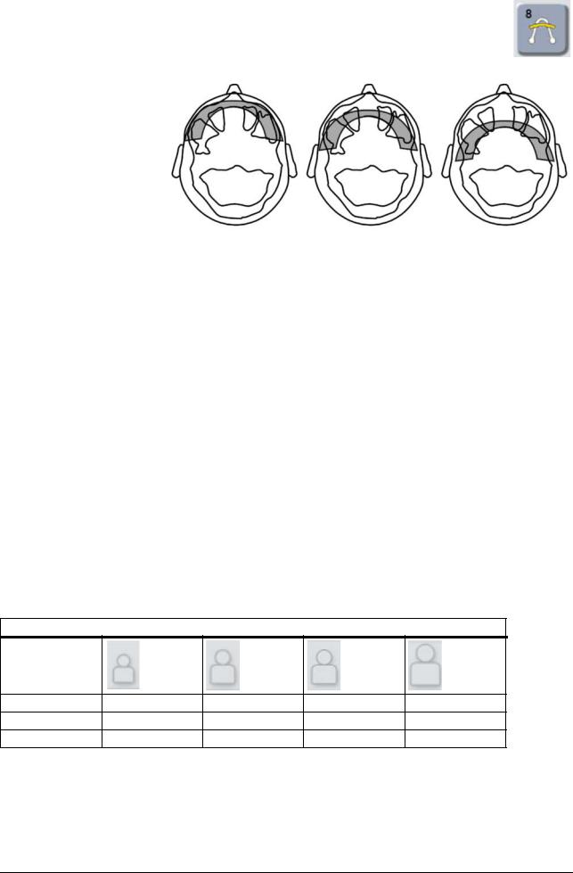
Ortho Zone: Magnification 1.25
The Ortho Zone program produces two different scanning geometries combined in the same image.
The first geometry (#1 and #3 in the figure) gives a standard panoramic view of the molar region.
The result of this scanning location will allow for views of the TM joint and molar area without redundant shadows from the opposite side ramus obscuring the image. Patients with prosthetic condyles or other posterior radio opaque objects can have the opposite side successfully imaged.
The second view (#2 in the figure) produces an image of the anterior region with a very wide layer of focus (approx.
35 mm). This view may be helpful when diagnosing trauma, wired shut, severe class III malocclusion and uncooperative patients.
Exposure settings for Ortho Zone program
|
100 VAC |
66 kV/5 mA |
66 kV/8 mA |
66 kV/10 mA |
70 kV/13 mA |
|
230 VAC |
66 kV/5 mA |
66 kV/8 mA |
66 kV/10 mA |
70 kV/13 mA |
|
< default > |
|
18 |
Instrumentarium Dental |
210457 rev 7 |

3 Imaging programs
Orthogonal: Magnification 1.3
An optimized view of the dentition only with optimized angulation and reduced radiation.
Orthogonal program produces a panoramic view with modified projection geometry. The Y axis of the rotation path is changed to improved the beam angle to be closer to 90° to the interproximal surfaces. With this improvement, other trade off’s must be made. The ascending rami may
Y be lost and in adult patients and redundant shadows will be increased.
Exposure settings for Orthogonal program
|
100 VAC |
66 kV/5 mA |
66 kV/8 mA |
66 kV/10 mA |
70 kV/13 mA |
|
230 VAC |
66 kV/5 mA |
66 kV/8 mA |
66 kV/10 mA |
70 kV/13 mA |
|
< default > |
Wide arch: Magnification 1.3
Used when the patient has a wider than normal dental arch.
Exposure settings for Wide arch program
|
100 VAC |
66 kV/5 mA |
66 kV/8 mA |
66 kV/10 mA |
70 kV/13 mA |
|
230 VAC |
66 kV/5 mA |
66 kV/8 mA |
66 kV/10 mA |
70 kV/13 mA |
|
< default > |
|
210457 rev 7 |
Instrumentarium Dental |
19 |

3 Imaging programs
Ortho Lateral TMJ: Magnification 1.23
Ortho TMJ program provides a wide layer axially corrected views for the patient’s left and right temporomandibular joints.
Exposure settings for Ortho Lateral TMJ program
|
100 VAC |
73 kV/6.3 mA |
73 kV/10 mA |
73 kV/13 mA |
73 kV/16 mA |
|
230 VAC |
73 kV/6.3 mA |
73 kV/10 mA |
73 kV/13 mA |
73 kV/16 mA |
|
< default > |
PA TMJ: Magnification 1.55
Exposure settings for PA TMJ program
|
100 VAC |
73 kV/6.3 mA |
73 kV/10 mA |
73 kV/13 mA |
73 kV/16 mA |
|
230 VAC |
73 kV/6.3 mA |
73 kV/10 mA |
73 kV/13 mA |
73 kV/16 mA |
|
< default > |
|
20 |
Instrumentarium Dental |
210457 rev 7 |
3 Imaging programs
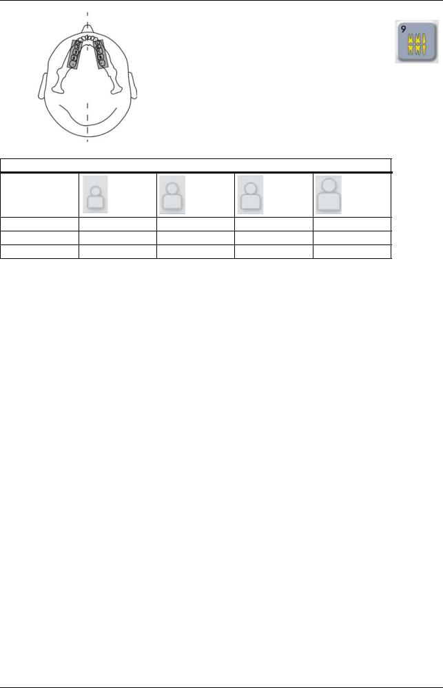
Maxillary Sinus: Magnification 1.3
|
Mesial 10 mm |
Start |
Distal 10 mm |
Maxillary Sinus program produces a pan — tomographic layer through the posterior maxillary sinus. The layer is flatter than the standard panoramic programs and is moved 18 mm backward. These images are helpful in visualizing the mid and posterior maxillary sinus.
Exposure settings for Maxillary Sinus program
|
100 VAC |
66 kV/6.3 mA |
66 kV/10 mA |
66 kV/13 mA |
73 kV/13 mA |
|
230 VAC |
66 kV/6.3 mA |
66 kV/10 mA |
66 kV/13 mA |
73 kV/13 mA |
|
< default > |
|
210457 rev 7 |
Instrumentarium Dental |
21 |
3 Imaging programs
Bitewing: Magnification 1.3
An orthogonal view of the dentition from the canine and posterior.
Exposure settings for Bitewing program
|
100 VAC |
66 kV/5 mA |
66 kV/8 mA |
66 kV/10 mA |
70 kV/13 mA |
|
230 VAC |
66 kV/5 mA |
66 kV/8 mA |
66 kV/10 mA |
70 kV/13 mA |
|
< default > |
|
22 |
Instrumentarium Dental |
210457 rev 7 |
![]()
3 Imaging programs
3.2 Cephalometric programs
Cephalometric pediatric lateral projection
Pediatric Lateral Cephalostat has an optimized image height (180 mm) that is used e.g. for pediatric patients but also adult patients to reduce the radiation dose. The pediatric lateral projection covers all the typical cephalostat landmarks from Nasion down to the spine and the starting point of the lateral scan is adjustable with both Standard and pediatric lateral cephalostat programs.
Exposure settings for cephalometric pediatric lateral program
|
100 VAC |
90 kV/8 mA/10 s |
90 kV/8 mA/13 s |
90 kV/8 mA/16 s |
90 kV/8 mA/20 s |
|
120 VAC |
85 kV/10 mA/ |
85 kV/10 mA/ |
90 kV/8 mA/16 s |
90 kV/8 mA/20 s |
|
10 s |
13 s |
|||
|
230 VAC |
85 kV/10 mA/ |
90 kV/10 mA/ |
90 kV/13 mA/ |
90 kV/13 mA/ |
|
13 s |
13 s |
16 s |
20 s |
|
|
< default > |
Cephalometric lateral projection
Lateral Cephalostat uses a full height image field (223 mm).
Exposure settings for cephalometric lateral program
|
100 VAC |
90 kV/8 mA/10 s 90 kV/8 mA/13 s 90 kV/8 mA/16 s 90 kV/8 mA/20 s |
|
120 VAC |
85 kV/10 mA/10 s 85 kV/10 mA/13 s 90 kV/10 mA/16 s 90 kV/10 mA/20 s |
|
230 VAC |
85 kV/10 mA/13 s 90 kV/10 mA/13 s 90 kV/13 mA/16 s 90 kV/13 mA/20 s |
|
< default > |
|
210457 rev 7 |
Instrumentarium Dental |
23 |

3 Imaging programs
Cephalo posterior-anterior (PA) projection
|
Reverse towne projection |
Waters view |
Exposure settings for cephalometric PA program
|
100 VAC |
90 kV/8 mA/10 s |
90 kV/8 mA/13 s |
90 kV/8 mA/16 s |
90 kV/8 mA/20 s |
|
120 VAC |
85 kV/10 mA/ |
85 kV/10 mA/ |
90 kV/10 mA/ |
90 kV/10 mA/ |
|
10 s |
13 s |
16 s |
20 s |
|
|
230 VAC |
85 kV/10 mA/ |
90 kV/10 mA/ |
90 kV/13 mA/ |
90 kV/13 mA/ |
|
13 s |
13 s |
16 s |
20 s |
|
|
< default > |
Carpus view (Not available in USA and Canada)
Exposure settings for Carpus view program
|
100 VAC |
66 kV/3,2 mA/ |
70 kV/3,2 mA/ |
73 kV/3,2 mA/ |
73 kV/6,3 mA/ |
|
120 VAC |
8 s |
8 s |
8 s |
8 s |
|
230 VAC |
||||
|
< default > |
|
24 |
Instrumentarium Dental |
210457 rev 7 |

3 Imaging programs
3.3 3D SFOV programs
61 x 41 mm FOV
High resolution (133μm voxel size)
Standard resolution (200μm voxel size)
Program for optimized endodontic imaging:
Endo program (85µm voxel size)
61 x 78 mm FOV
High resolution (200μm voxel size)
Standard resolution (300μm voxel size)
Exposure settings for 3D SFOV imaging (default values)
|
Resolution |
FOV |
kV |
mA |
Exposure |
|
|
(h x w) |
time |
||||
|
Endo program |
61 x 41 mm |
90 |
10 |
6,1 s |
|
|
High Res |
61 x 41 mm |
90 |
8 |
6,1 s |
|
|
Std Res |
61 x 41 mm |
90 |
10 |
2,3 s |
|
|
High Res |
61 x 78 mm |
90 |
6,3 |
13 s |
|
|
Std Res |
61 x 78 mm |
90 |
10 |
4,9 |
|
210457 rev 7 |
Instrumentarium Dental |
25 |

3 Imaging programs
3.4 3D MFOV (Maxio) programs
50 x 50 mm FOV
High resolution (125μm voxel size)
Standard resolution (200μm voxel size)
Low Dose Scan (280μm voxel size)
Program optimized for endodontic imaging:
Endo program (85µm voxel size)
61 x 78 mm FOV
High resolution (200μm voxel size)
Standard resolution (300μm voxel size)
Low Dose Scan (320μm voxel size)
|
26 |
Instrumentarium Dental |
210457 rev 7 |

3 Imaging programs
78 x 78 mm FOV
High resolution (200μm voxel size)
Standard resolution (300μm voxel size)
Low Dose Scan (320μm voxel size)
78 x 150 mm FOV
High resolution (250μm voxel size)
Standard resolution (350μm voxel size)
Low Dose Scan (400μm voxel size)
130 x 150 mm FOV
High resolution (320μm voxel size)
Standard resolution (380μm voxel size)
Low Dose Scan (420μm voxel size)
|
210457 rev 7 |
Instrumentarium Dental |
27 |

3 Imaging programs
3.5 Selecting resolution and FOV
The resolution selection has an effect to the image quality and to the patient dose. For example High resolution will give better image quality than Standard resolution, but on the other hand the patient dosage is also higher. The unit offers a Low Dose resolution (see Tables 1.1 & 1.4) which can be used for example in treatment follow-up cases. The Low Dose resolution will result in images of reduced image quality (in other words image quality is proportional to dose) and it is up to the dental professional to decide when it is sufficient to use this mode. As small as possible FOV size should be selected for the patient case in order to follow the ALARA (As Low As Reasonably Achievable) principle.
Table 1.1 General guidelines for selecting 3D resolution. It is always up to the dental professional to select the appropriate mode.
|
Resolution setting |
General recommendations for the use |
|
Low Dose Resolution |
Treatment follow up, children |
|
Standard Resolution |
Implants, 3rd molars, TMJ, impacted teeth, resorptions |
|
High Resolution |
Pathologies, alveolar bone defects, root fractures |
|
Endo Resolution |
Endodontic cases (periapical infections, root canals, fractures, etc.) |
Table 1.2 General guidelines for selecting 3D FOV. It is always up to the dental professional to select the appropriate mode.
|
Resolution setting |
General recommendations for the use |
|
SFOV 61 x 41 mm |
Optimized for single site implants or localized diagnostics, for ex- |
|
MFOV 50 x 50 mm |
ample 3rd molar extractions, impacted teeth´s, single TMJ analy- |
|
sis, endodontics, and children. |
|
|
SFOV 61 x 78 mm |
Multiple implant placement using surgical guides, covers complete |
|
MFOV |
dental arch, optimized for one jaw. |
|
MFOV 78 x 78 mm |
Entire dentition, both mandibula and maxilla as well as a portion of |
|
maxillary sinus. |
|
|
MFOV 78 x 150 mm |
Both mandibula and maxilla including airway and upper cervical |
|
spine or the sinus, both TM joints. |
|
|
MFOV 130 x 150 mm |
Covers entire maxillofacial region, from maxilla to frontal |
|
sinus or from mandibula to maxillary sinus. |
|
|
• |
|
28 |
Instrumentarium Dental |
210457 rev 7 |

3 Imaging programs
3.6 MAR, Metal Artifact Reduction
|
MAR, Metal Artifact Reduction software can be used to |
|
|
reduce the effect of metals and other dense radiopaque |
|
|
objects on the 3D image. These create artifacts that are |
|
|
seen typically as stripes and shadows from the above- |
|
|
mentioned objects. To utilize MAR on a 3D image may |
|
|
MAR-button is OFF. |
have affect to image reconstruction time |
3D SFOV touch screen: MAR-button is ON.
MAR-button becomes visible on the 3D modality.
MFOV (Maxio) touch screen: MAR-button is ON.
MAR-button becomes visible on the 3D modality.
|
210457 rev 7 |
Instrumentarium Dental |
29 |

3 Imaging programs
3.7 Exposure settings for 3D imaging
Table 1.3
Exposure settings for 3D SFOV imaging
Note! Voltage settings is always 90kV with the unit 3D modality.
|
Resolution |
FOV |
Exposure |
Scanning |
Amount of |
mA |
mA |
mA |
|
(h x w) |
time |
time |
projections |
Low dose |
default |
High-quality |
|
|
(DAP |
(DAP |
(DAP |
|||||
|
mGycm2) |
mGycm2) |
mGycm2) |
|||||
|
High Res |
61 x 41 mm |
6,1 s |
10 s |
609 |
6.3 mA |
8 mA |
13 mA |
|
(240) |
(385) |
(601) |
|||||
|
Std Res |
61 x 41 mm |
2,3 s |
10 s |
234 |
8 mA |
10 mA |
13 mA |
|
(148) |
(184) |
(231) |
|||||
|
Endo Res |
61 x 41 mm |
6,1 s |
10 s |
609 |
8 mA |
10 mA |
13 mA |
|
(385) |
(476) |
(601) |
|||||
|
High Res |
61 x 78 mm |
12,6 s |
20 s |
1262 |
5 mA |
6.3 mA |
10 mA |
|
(498) |
(619) |
(996) |
|||||
|
Std Res |
61 x 78 mm |
4,9 s |
20 s |
486 |
8 mA |
10 mA |
13 mA |
|
(306) |
(372) |
(479) |
Table 1.4
Exposure settings for 3D imaging, MFOV (Maxio)
Note! Voltage settings is always 90kV with the unit 3D modality.
|
3D program |
FOV |
Exposure |
Project- |
Scanning |
Default |
mAs |
DAP |
Voxel |
|
(h x w) |
time |
ions |
time |
mA |
(mGycm2) |
(um) |
||
|
Low Dose |
50 x 50 mm |
1,17 s |
234 |
10,96 s |
3,2 mA |
3,7 |
32 |
280 |
|
Std Res |
50 x 50 mm |
2,34 s |
234 |
10,96 s |
8 mA |
18,7 |
162 |
200 |
|
High Res |
50 x 50 mm |
6,09 s |
609 |
17,4 s |
6,3 mA |
38,4 |
332 |
125 |
|
Endo Res |
50 x 50 mm |
8,7 s |
870 |
17,4 s |
5 mA |
43,5 |
377 |
85 |
|
Low Dose |
61 x 78 mm |
1,17 s |
234 |
10,96 s |
3,2 mA |
3,7 |
58 |
320 |
|
Std Res |
61 x 78 mm |
2,34 s |
234 |
10,96 s |
8 mA |
18,7 |
288 |
300 |
|
High Res |
61 x 78 mm |
6,09 s |
609 |
17,4 s |
6,3 mA |
38,4 |
591 |
200 |
|
Low Dose |
78 x 78 mm |
1,17 s |
234 |
10,96 s |
3,2 mA |
3,7 |
72 |
320 |
|
Std Res |
78 x 78 mm |
2,34 s |
234 |
10,96 s |
8 mA |
18,7 |
358 |
300 |
|
High Res |
78 x 78 mm |
6,09 s |
609 |
17,4 s |
6,3 mA |
38,4 |
735 |
200 |
|
Low Dose |
78 x 150 mm |
2,25 s |
450 |
19,5 s |
3,2 mA |
7,2 |
138 |
400 |
|
Std Res |
78 x 150 mm |
4,5 s |
450 |
19,5 s |
6.3 mA |
28,4 |
543 |
350 |
|
High Res |
78 x 150 mm |
8,5 s |
850 |
24,3 s |
5 mA |
42,5 |
814 |
250 |
|
Low Dose |
130 x 150 mm |
4,5 s |
900 |
40 s |
6.3 mA |
14,4 |
276 |
420 |
|
Std Res |
130 x 150 mm |
9,0 s |
900 |
40 s |
4 mA |
36,0 |
690 |
380 |
|
High Res |
130 x 150 mm |
9,0 s |
900 |
40 s |
6,3 mA |
56,7 |
1086 |
320 |
DAP values vary from unit to unit in relation to the x-ray tube output. Thus above values indicate average DAP values. In addition to these recommended values, there is a possibility to use the whole mA range if the user prefers.
|
30 |
Instrumentarium Dental |
210457 rev 7 |

3 Imaging programs
Available mA ranges for each field of view sizes and resolution settings (3D SFOV)
|
Resolution |
FOV |
4 mA |
5 mA |
6.3 mA |
8 mA |
10 mA |
13 mA |
|
(h x w) |
|||||||
|
Endo Res |
61 x 41 mm |
x |
x |
x |
x |
x |
x |
|
High Res |
61 x 41 mm |
x |
x |
x |
x |
x |
x |
|
Std Res |
61 x 41 mm |
x |
x |
x |
x |
||
|
High Res |
61 x 78 mm |
x |
x |
x |
x |
x |
|
|
Std Res |
61 x 78 mm |
x |
x |
x |
x |
Available mA ranges for each field of view sizes and resolution settings (MFOV (Maxio))
|
Resolution |
FOV |
3.2 mA |
4 mA |
5 mA |
6.3 mA |
8 mA |
10 mA |
12,5 mA |
|
(h x w) |
||||||||
|
Low Dose |
50 x 50 mm |
x |
x |
x |
x |
|||
|
Std Res |
50 x 50 mm |
x |
x |
x |
x |
x |
||
|
High Res |
50 x 50 mm |
x |
x |
x |
x |
x |
x |
|
|
Endo Res |
50 x 50 mm |
x |
x |
x |
x |
x |
x |
|
|
Low Dose |
61 x 78 mm |
x |
x |
x |
||||
|
Std Res |
61 x 78 mm |
x |
x |
x |
x |
x |
||
|
High Res |
61 x 78 mm |
x |
x |
x |
x |
x |
||
|
Low Dose |
78 x 78 mm |
x |
||||||
|
Std Res |
78 x 78 mm |
x |
x |
x |
x |
x |
||
|
High Res |
78 x 78 mm |
x |
x |
x |
x |
x |
||
|
Low Dose |
78 x 150 mm |
x |
||||||
|
Std Res |
78 x 150 mm |
x |
x |
x |
x |
x |
||
|
High Res |
78 x 150 mm |
x |
x |
x |
x |
x |
||
|
Low Dose |
130 x 150 mm |
x |
||||||
|
Std Res |
130 x 150 mm |
x |
x |
x |
x |
x |
||
|
High Res |
130 x 150 mm |
x |
x |
x |
x |
x |
Exposure settings for scout imaging (3D SFOV, default values)
|
Resolution |
FOV |
kV |
mA |
Scanning |
|
(h x w) |
time |
|||
|
Scout |
61 x 41 mm |
90 |
13 |
0,02 s |
|
Scout |
61 x 78 mm |
90 |
13 |
0,04 s |
Exposure settings for scout imaging (MFOV (Maxio), default values)
|
Resolution |
FOV |
kV |
mA |
Scanning |
|
(h x w) |
time |
|||
|
Scout |
50 x 50 mm |
90 |
13 |
0,02 s |
|
Scout |
61 x 78 mm |
90 |
13 |
0,02 s |
|
Scout |
78 x 78 mm |
90 |
13 |
0,02 s |
|
Scout |
78 x 150 mm |
90 |
13 |
0,04 s |
|
Scout |
130 x 150 mm |
90 |
13 |
0,08 s |
|
210457 rev 7 |
Instrumentarium Dental |
31 |

3 Imaging programs
|
32 |
Instrumentarium Dental |
210457 rev 7 |
 Loading…
Перейти к контенту
![]()
Русские электронные инструкции по эксплуатации
Постоянно обновляемый большой каталог документации по эксплуатации и использованию современных устройств и оборудования на русском языке. Бесплатное скачивание файлов.
Поиск:
Главная
♥ В закладки
Просмотр инструкции в pdf


Инструкция по эксплуатации мультиварки NINJA OP300EU.
Скачать инструкцию к мультиварке NINJA OP300EU (10,98 МБ)

Инструкции мультиварок NINJA
« Инструкция к мультиварке Goodhelper МС-5200
» Инструкция к мультиварке Redmond RMC-M4503
Вам также может быть интересно

Инструкция к мультиварке NINJA OP500EU

Инструкция к газовой варочной панели Maunfeld EGHG.64.2CW-G White
/%D0%A1%D1%82%D0%B8%D1%80%D0%B0%D0%BB%D1%8C%D0%BD%D1%8B%D0%B5%20%D0%BC%D0%B0%D1%88%D0%B8%D0%BD%D1%8B/%20%D0%BC%D0%B0%D1%88%D0%B8%D0%BD%D0%B0%20%D1%83%D0%B7%D0%BA%D0%B0%D1%8F%20Bosch%20Serie%20|%206%20WLL24360OE.jpg)
Инструкция к стиральной машине Bosch (Бош) машина узкая Bosch Serie | 6 WLL24360OE

Инструкция к кофеварке Tefal Confidence CM361838

Инструкция к умным часам Digma Smartline D3 1,3″ TFT Black

Инструкция к электрокамину Scarlett SC-2055
.jpg)
Инструкция к смартфону realme 5 3+64GB Purple (RMX1927)

Инструкция к мультиварке Garlyn MR-Duo 5
Добавить комментарий
Имя *
Email *
Сайт
Комментарий


![]()


Сохранить моё имя, email и адрес сайта в этом браузере для последующих моих комментариев.
- Добавить инструкцию
- Заказать инструкцию
- Политика конфиденциальности