
Содержание
-
Safety Information
15
-
Case stand-off notification
16
-
Avoid collision notification
16
-
-
Specifications
17
-
Package contents
24
-
Rear I/O Panel
25
-
LAN Port LED Status Table
25
-
Audio Ports Configuration
25
-
Realtek Audio Console
26
-
-
Overview of Components
29
-
CPU Socket
30
-
DIMM Slots
31
-
PCI_E1~4: PCIe Expansion Slots
32
-
JFP1, JFP2: Front Panel Connectors
32
-
M2_1~4: M.2 Slots (Key M)
33
-
SATA1~6: SATA 6Gb/s Connectors
35
-
JAUD1: Front Audio Connector
35
-
CPU_PWR1~2, ATX_PWR1: Power Connectors
36
-
JDASH1 : Tuning Controller connector
37
-
JCI1: Chassis Intrusion Connector
37
-
JUSB4: USB 3.2 Gen 2 Type-C Connector
38
-
JUSB3: USB 3.2 Gen 1 Connector
38
-
JUSB1~2: USB 2.0 Connectors
39
-
JTPM1: TPM Module Connector
39
-
CPU_FAN1, PUMP_FAN1, SYS_FAN1~6: Fan Connectors
40
-
JBAT1: Clear CMOS (Reset BIOS) Jumper
41
-
JTBT1: Thunderbolt Add-on Card Connector
41
-
JRGB1: RGB LED connector
42
-
JRAINBOW1~3: Addressable RGB LED connectors
43
-
-
Onboard LEDs
44
-
EZ Debug LED
44
-
LED_SW1: EZ LED Control
44
-
-
Installing OS, Drivers & MSI Center
45
-
Installing Windows 10/ Windows 11
45
-
Installing Drivers
45
-
MSI Center
45
-
-
UEFI BIOS
46
-
BIOS Setup
47
-
Resetting BIOS
48
-
Updating BIOS
48
-
-
Sicherheitshinweis
52
-
Hinweise zum Gehäuseabstandshalter
53
-
Hinweis zur Schadensvermeidung
53
-
-
Spezifikationen
54
-
Packungsinhalt
62
-
Rückseite E/A
63
-
LAN Port LED Zustandstabelle
63
-
Konfiguration der Audioanschlüsse
63
-
Realtek Audio Console
64
-
-
Übersicht der Komponenten
67
-
CPU Sockel
68
-
DIMM Steckplätze
69
-
PCI_E1~4: PCIe Erweiterungssteckplätze
70
-
JFP1, JFP2: Frontpanel-Anschlüsse
70
-
M2_1~4: M.2 Steckplätze (Key M)
71
-
SATA1~6: SATA 6Gb/s Anschlüsse
73
-
JAUD1: Audioanschluss des Frontpanels
73
-
CPU_PWR1~2, ATX_PWR1: Stromanschlüsse
74
-
JDASH1: Tuning Controller-Anschluss
75
-
JCI1: Gehäusekontaktanschluss
75
-
JUSB4: USB 3.2 Gen 2 Typ-C Anschluss
76
-
JUSB3: USB 3.2 Gen 1 Anschluss
76
-
JUSB1~2: USB 2.0 Anschlüsse
77
-
JTPM1: TPM Anschluss
77
-
CPU_FAN1, PUMP_FAN1, SYS_FAN1~6: Stromanschlüsse für Lüfter
78
-
JBAT1: Clear CMOS Steckbrücke (Reset BIOS)
79
-
JTBT1: Anschluss für Thunderbolt-Erweiterungskarte
79
-
JRGB1: RGB LED Anschluss
80
-
JRAINBOW1~3: Adressierbarer RGB-LED-Streifen Anschlüsse
81
-
-
Onboard LEDs
82
-
EZ DEBUG LED
82
-
LED_SW1: EZ LED Steuerung
82
-
-
Installation von OS, Treibern & MSI Center
83
-
Installation von Windows 10/ Windows 11
83
-
Installation von Treibern
83
-
MSI Center
84
-
-
UEFI BIOS
85
-
BIOS Setup
86
-
Öffnen des BIOS Setups
86
-
BIOS-Benutzerhandbuch
86
-
Reset des BIOS
87
-
Aktualisierung des BIOS
87
-
-
Informations de sécurité
91
-
Avertissement pour l’installation des entretoises
92
-
Zone de protection
92
-
-
Spécifications
93
-
Contenu
101
-
Panneau arrière Entrée/Sortie
102
-
Tableau explicatif de l’état de la LED du port LAN
102
-
Configuration des ports audio
102
-
Realtek Audio Console
103
-
-
Vue d’ensemble des composants
106
-
Socket Processeur
107
-
Slots DIMM
108
-
PCI_E1~4 : Slots d’extension PCIe
109
-
JFP1, JFP2 : Connecteurs de panneau avant
109
-
M2_1~4 : Slots M.2 (Touche M)
110
-
SATA1~6 : Connecteurs SATA 6 Gb/s
112
-
JAUD1 : Connecteur audio avant
112
-
CPU_PWR1~2, ATX_PWR1 : Connecteurs d’alimentation
113
-
JDASH1 : Connecteur du contrôleur de réglages
114
-
JCI1 : Connecteur intrusion châssis
114
-
JUSB4 : Connecteur USB 3.2 Gen 2 Type-C
115
-
JUSB3 : Connecteur USB 3.2 Gen 1
115
-
JUSB1~2 : Connecteurs USB 2.0
116
-
JTPM1 : Connecteur de module TPM
116
-
CPU_FAN1, PUMP_FAN1, SYS_FAN1~6 : Connecteurs de ventilateur
117
-
JBAT1 : Cavalier Clear CMOS (Réinitialiser le BIOS)
118
-
JTBT1 : Connecteur de carte additionnelle Thunderbolt
118
-
JRGB1 : Connecteur LED RGB
119
-
JRAINBOW1~3 : Connecteurs LED RGB adressables
120
-
-
LED embarquées
121
-
EZ Debug LED
121
-
LED_SW1 : Contrôle EZ LED
121
-
-
Installer OS, Pilotes et MSI Center
122
-
Installer Windows 10/ Windows 11
122
-
Installer les pilotes
122
-
MSI Center
123
-
-
UEFI BIOS
124
-
Configuration du BIOS
125
-
Entrer dans la configuration du BIOS
125
-
Guide d’utilisation du BIOS
125
-
Réinitialiser le BIOS
126
-
Mettre le BIOS à jour
126
-
-
Безопасное использование продукции
130
-
Уведомление о стойках для крепления материнской платы
131
-
Избегайте ударов
131
-
-
Технические характеристики
132
-
Комплект поставки
139
-
Задняя панель портов ввода/ вывода
140
-
Таблица состояний индикатора порта LAN
140
-
Конфигурация портов Аудио
140
-
Realtek Audio Console
141
-
-
Компоненты материнской платы
144
-
Процессорный сокет
145
-
Слоты DIMM
146
-
PCI_E1~4: Слоты расширения PCIe
147
-
JFP1, JFP2: Разъемы передней панели
147
-
M2_1~4: Разъемы M.2 (Ключ M)
148
-
SATA1~6: Разъемы SATA 6Гб/с
150
-
JAUD1: Разъем аудио передней панели
150
-
CPU_PWR1~2, ATX_PWR1: Разъемы питания
151
-
JDASH1: Разъем контроллера настройки
152
-
JCI1: Разъем датчика открытия корпуса
152
-
JUSB4: Разъем USB 3.2 Gen 2 Type-C
153
-
JUSB3: Разъем USB 3.2 Gen 1
153
-
JUSB1~2: Разъемы USB 2.0
154
-
JTPM1: Разъем модуля ТРМ
154
-
CPU_FAN1, PUMP_FAN1, SYS_FAN1~6: Разъемы вентиляторов
155
-
JBAT1: Джампер очистки данных CMOS (Сброс BIOS)
156
-
JTBT1: Разъем для установки карты расширения Thunderbolt
156
-
JRGB1: Разъем RGB LED
157
-
JRAINBOW1~3: Разъемы адресных RGB LED
158
-
-
Встроенные индикаторы
159
-
Индикаторы отладки EZ
159
-
LED_SW1: Переключатель для управления индикаторами
159
-
-
Установка ОС, драйверов и MSI Center
160
-
Установка Windows 10/ Windows 11
160
-
Установка драйверов
160
-
MSI Center
160
-
-
UEFI BIOS
161
-
Настройка BIOS
162
-
Вход в настройки BIOS
162
-
Инструкции по настройке BIOS
162
-
Сброс BIOS
163
-
Обновление BIOS
163
-
-
安全に関する注意事項
167
-
ケーススタンドオフの注意事項
168
-
衝突を避ける注意事項
168
-
-
仕様
169
-
パッケージの内容
176
-
リアI/Oパネル
177
-
LANポートLED状態表
177
-
オーディオポートの配置
177
-
Realtekオーディオコンソール
178
-
-
コンポーネントの概要
181
-
CPUソケット
182
-
DIMMスロット
183
-
PCI_E1~4: PCIe拡張スロット
184
-
JFP1、JFP2: フロントパネルコネクター
184
-
M2_1~4: M.2スロット (Key M)
185
-
SATA1~6: SATA 6Gb/sコネクター
187
-
JAUD1: フロントオーディオコネクター
187
-
CPU_PWR1~2、ATX_PWR1: 電源コネクター
188
-
JDASH1 : チューニングコントローラーコネクター
189
-
JCI1: ケース開放スイッチコネクター
189
-
JUSB4: USB 3.2 Gen 2 Type-Cコネクター
190
-
JUSB3: USB 3.2 Gen 1コネクター
190
-
JUSB1~2: USB 2.0コネクター
191
-
JTPM1: TPMモジュールコネクター
191
-
CPU_FAN1、PUMP_FAN1、SYS_FAN1~6: ファンコネクター
192
-
JBAT1: クリアCMOS (BIOSリセット) ジャンパ
193
-
JTBT1: Thunderbolt追加カードコネクター
193
-
JRGB1: RGB LEDコネクター
194
-
JRAINBOW1~3: 追加のRGB LEDコネクター
195
-
-
オンボードLED
196
-
EZ Debug LED
196
-
LED_SW1: EZ LEDコントロール
196
-
-
OS、ドライバーおよびMSI Centerのインストール
197
-
Windows 10/ Windows 11のインストール
197
-
ドライバーのインストール
197
-
MSI Center
197
-
-
UEFI BIOS
198
-
BIOSの設定
199
-
BIOSセットアップ画面の起動
199
-
BIOSユーザーズガイド
199
-
BIOSのリセット
200
-
BIOSのアップデート方法
200
-
-
안전 지침
204
-
케이스 스탠드 오프 알림
205
-
충돌 방지 알림
205
-
-
사양
206
-
제품 내용물
213
-
후면 I/O 패널
214
-
LAN 포트 LED 상태 표시
214
-
오디오 포트 구성 도표
214
-
Realtek 오디오 콘솔
215
-
-
구성품 개요
218
-
CPU 소켓
219
-
DIMM 슬롯
220
-
PCI_E1~4: PCIe 확장 슬롯
221
-
JFP1, JFP2: 전면 패널 커넥터
221
-
M2_1~4: M.2 슬롯 (Key M)
222
-
SATA1~6: SATA 6Gb/s 커넥터
224
-
JAUD1: 전면 오디오 커넥터
224
-
CPU_PWR1~2, ATX_PWR1: 전원 커넥터
225
-
JDASH1 : 튜닝 컨트롤러 커넥터
226
-
JCI1: 섀시 침입 커넥터
226
-
JUSB4: USB 3.2 Gen 2 Type-C 커넥터
227
-
JUSB3: USB 3.2 Gen 1 커넥터
227
-
JUSB1~2: USB 2.0 커넥터
228
-
JTPM1: TPM 모듈 커넥터
228
-
CPU_FAN1, PUMP_FAN1, SYS_FAN1~6:팬 커넥터
229
-
JBAT1: CMOS (Reset BIOS) 클리어 점퍼
230
-
JTBT1: 썬더볼트 추가 카드 커넥터
230
-
JRGB1: RGB LED 커넥터
231
-
JRAINBOW1~3: 주소 지정 가능한 RGB LED 커넥터
232
-
-
온보드 LEDs
233
-
EZ 디버그 LED
233
-
LED_SW1: EZ LED 컨트롤
233
-
-
OS, 드라이버 & MSI 센터 설치하기
234
-
Windows 10/ Windows 11 설치하기
234
-
드라이버 설치하기
234
-
MSI 센터
234
-
-
UEFI BIOS
235
-
BIOS (바이오스) 설정
236
-
BIOS 설정
236
-
BIOS 리셋
237
-
BIOS(바이오스) 업데이트
237
-
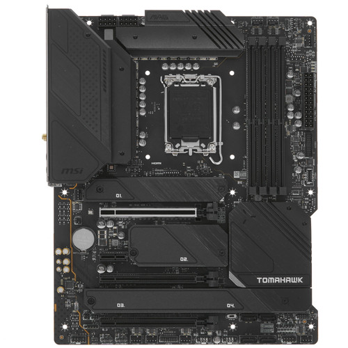
View the manual for the MSI MAG Z690 Tomahawk WIFI here, for free. This manual comes under the category motherboards and has been rated by 2 people with an average of a 9.2. This manual is available in the following languages: English. Do you have a question about the MSI MAG Z690 Tomahawk WIFI or do you need help? Ask your question here
The MSI MAG Z690 Tomahawk WIFI is a motherboard designed for high-performance computing. It supports various memory clock speeds, including 4000, 5400, and 6400 MHz, allowing for fast and efficient data processing. With three PCI Express x16 slots and one PCI Express x1 (Gen 3.x) slot, it offers ample expansion options for additional devices.
Equipped with Crossfire parallel processing technology support, this motherboard allows for multiple graphics cards to be used simultaneously, enhancing graphics performance. It does not include a DVI-D or VGA (D-Sub) port but provides one HDMI and one DisplayPort, supporting versions 2.1 and 1.4 respectively, for high-quality visual output.
Featuring four M.2 (M) slots, the motherboard allows for fast and efficient storage options. This is particularly beneficial for data-intensive applications or users who require large storage capacities.
For audio output, the motherboard offers 7.1 channels, providing immersive sound experiences. It utilizes the Realtek ALC4080 audio chip, ensuring high-quality audio performance.
Additionally, the MSI MAG Z690 Tomahawk WIFI includes built-in 2.5 Gigabit Ethernet, offering fast and reliable network connectivity. This allows for seamless online gaming, high-speed downloads, and smooth streaming experiences.
Constructed with premium materials, this motherboard prioritizes reliability and durability. It is designed to withstand extended usage and maintain consistent performance over time.
Overall, the MSI MAG Z690 Tomahawk WIFI is a feature-rich motherboard that offers high-performance computing capabilities, expandability options, and reliable connectivity for a seamless user experience.
General
| MSI | |
| MAG Z690 Tomahawk WIFI | MAG Z690 TOMAHAWK WIFI | |
| motherboard | |
| 4719072896683 | |
| English | |
| User manual (PDF) |
Memory
| Supported memory clock speeds | 4000,5400,6400 MHz |
| Maximum internal memory | 128 GB |
| Unbuffered memory | Yes |
| Non-ECC | Yes |
| Supported memory types | DDR5-SDRAM |
| Number of memory slots | 4 |
| Memory slots type | DIMM |
| Memory channels | Dual-channel |
Expansion slots
| PCI Express x16 slots | 3 |
| PCI Express x1 (Gen 3.x) slots | 1 |
| Number of M.2 (M) slots | 4 |
Graphics
| Parallel processing technology support | Crossfire |
Rear panel I/O ports
| DVI-D ports quantity | 0 |
| HDMI ports quantity | 1 |
| VGA (D-Sub) ports quantity | 0 |
| DisplayPorts quantity | 1 |
| DisplayPort version | 1.4 |
| HDMI version | 2.1 |
| Ethernet LAN (RJ-45) ports | 1 |
| USB 2.0 ports quantity | 2 |
| USB 3.2 Gen 2 (3.1 Gen 2) Type-A ports quantity | 3 |
| WiFi-AP antenna jack | 2 |
| USB 3.2 Gen 1 (3.1 Gen 1) Type-A ports quantity | 2 |
| USB 3.2 Gen 2×2 Type-C ports quantity | 1 |
| USB 3.2 Gen 2 (3.1 Gen 2) Type-C ports quantity | 0 |
| USB 3.2 Gen 1 (3.1 Gen 1) Type-C ports quantity | 0 |
| S/PDIF out port | Yes |
| Digital audio optical out | 1 |
Features
| Audio output channels | 7.1 channels |
| Audio chip | Realtek ALC4080 |
| Component for | PC |
| Motherboard form factor | ATX |
| Motherboard chipset family | Intel |
| Motherboard chipset | Intel Z690 |
Network
| Ethernet LAN | Yes |
| Ethernet interface type | 2.5 Gigabit Ethernet |
| LAN controller | Intel I225-V |
| Wi-Fi | Yes |
| Top Wi-Fi standard | Wi-Fi 6E (802.11ax) |
| Wi-Fi standards | 802.11a, 802.11b, 802.11g, Wi-Fi 4 (802.11n), Wi-Fi 5 (802.11ac), Wi-Fi 6 (802.11ax) |
| Bluetooth | Yes |
| Bluetooth version | 5.2 |
Internal I/O
| ATX Power connector (24-pin) | Yes |
| USB 2.0 connectors | 2 |
| 12V power connector | Yes |
| USB 3.2 Gen 1 (3.1 Gen 1) connectors | 1 |
| USB 3.2 Gen 2 (3.1 Gen 2) connectors | 0 |
| Number of SATA III connectors | 6 |
| CPU fan connector | Yes |
| Number of chassis fan connectors | 6 |
| Chassis intrusion connector | Yes |
| TPM connector | Yes |
| Front panel audio connector | Yes |
BIOS
| Clear CMOS jumper | Yes |
| BIOS type | UEFI AMI |
Weight & dimensions
| Width | 305 mm |
| Depth | 244 mm |
| Height | 65 mm |
Packaging content
| Drivers included | Yes |
| Cables included | SATA |
Storage controllers
| Supported storage drive types | HDD & SSD |
| Supported storage drive interfaces | M.2, SATA III |
| RAID support | Yes |
| RAID levels | 0, 1,5, 10 |
Processor
| Processor manufacturer | Intel |
| Processor socket | LGA 1700 |
| Maximum number of SMP processors | 1 |
| Compatible processor series | Intel Celeron, Intel Core i3, Intel Core i5, Intel Core i7, Intel Core i9, Intel Pentium |
Logistics data
| Harmonized System (HS) code | 84733020 |
Other features
show more
Can’t find the answer to your question in the manual? You may find the answer to your question in the FAQs about the MSI MAG Z690 Tomahawk WIFI below.
What is the weight of the MSI MAG Z690 Tomahawk WIFI?
The MSI MAG Z690 Tomahawk WIFI has a weight of 1000 g.
What is the height of the MSI MAG Z690 Tomahawk WIFI?
The MSI MAG Z690 Tomahawk WIFI has a height of 65 mm.
What is the width of the MSI MAG Z690 Tomahawk WIFI?
The MSI MAG Z690 Tomahawk WIFI has a width of 305 mm.
What is the depth of the MSI MAG Z690 Tomahawk WIFI?
The MSI MAG Z690 Tomahawk WIFI has a depth of 244 mm.
How do I install the MSI MAG Z690 Tomahawk WIFI motherboard?
Firstly, place the motherboard onto the case and align the screw holes. Then, securely fasten the motherboard using the provided screws. Connect the necessary power cables, such as the 24-pin ATX power connector and the CPU power connector. Finally, connect the front panel connectors for power buttons, USB ports, etc.
How can I update the BIOS on my MSI MAG Z690 Tomahawk WIFI?
Begin by downloading the latest BIOS version from MSI’s official website. Save the BIOS file onto a USB flash drive. Restart your computer and access the BIOS by pressing the designated key during startup. Then, navigate to the «Flash BIOS» or «Update BIOS» section, select the USB drive containing the BIOS file, and follow the on-screen prompts to complete the update.
What should I do if my computer does not power on with the MSI MAG Z690 Tomahawk WIFI?
Ensure that all power cables are securely connected, including the motherboard power connectors and the power supply cables. Also, check if the power supply switch is turned on. You may want to reseat the RAM modules, CPU, and graphics card to ensure they are properly inserted. If the issue persists, try booting the system with minimal components installed to identify any potential hardware compatibility or failure issues.
How do I connect front panel connectors to the MSI MAG Z690 Tomahawk WIFI?
Refer to the motherboard’s user manual for the detailed pin layout and connection instructions of the front panel connectors. Generally, they include power switch, reset switch, HDD LED, power LED, and audio connectors. The manual will provide specific details on where these connectors should be plugged in on the motherboard.
What is the maximum RAM capacity supported by the MSI MAG Z690 Tomahawk WIFI?
The MSI MAG Z690 Tomahawk WIFI supports a maximum RAM capacity of 128GB across four DIMM slots. It is compatible with DDR4 memory modules with frequencies of up to 6400MHz (OC). Make sure to consult the motherboard manual for specific details on memory configurations and recommended installation guidelines.
Is the manual of the MSI MAG Z690 Tomahawk WIFI available in English?
Yes, the manual of the MSI MAG Z690 Tomahawk WIFI is available in English .
Is your question not listed? Ask your question here
3.0
Rated 3.0 out of 5
3.0 out of 5 stars (based on 1 review)
Your overall rating
MSI MAG Z690 TOMAHAWK WIFI (01) PDF MANUAL
Click here to download MSI MAG Z690 TOMAHAWK WIFI (01) PDF MANUAL
MSI MAG Z690 TOMAHAWK WIFI (01) PDF MANUAL
FREE ENGLISH PDF
OPERATING INSTRUCTIONS
USER GUIDE – USER MANUAL
OWNER GUIDE – OWNER MANUAL
REFERENCE GUIDE – REFERENCE MANUAL
INSTRUCTION GUIDE – INSTRUCTION MANUAL
Your overall rating
- YouTube
MSI MAG Z690 TOMAHAWK WIFI (01) PDF MANUAL
MSI MAG Z690 TOMAHAWK WIFI (01) PDF MANUAL
Материнская плата MSI MAG Z690 TOMAHAWK WIFI DDR4
LGA 1700, Intel Z690, 4xDDR4-3200 МГц, 3xPCI-Ex16, 4xM.2, Standard-ATX
подробнее

177
Код товара: 4880518