
Life Scope i
BEDSIDE MONITOR
BSM-2301A/2304A
Life Scope L
BEDSIDE MONITOR
BSM-2351A
0614-006206H

line cutting
Model: BSM-2301A/2304A/2351A
Manual code no.: 0614-006206H
Reader Comment Card
We welcome your comments about this manual. Your comments and suggestions help us improve our manuals. Please circle the number for each of the following statements corresponding to your evaluation and add comments in the space provided.
Fax or send your completed comment card to:
Fax: +81 (3) 5996-8100
International Div., Sales Promotion Section, Nihon Kohden Corp., 1-31-4, Nishiochiai Shinjuku-ku, Tokyo 161-8560, Japan
|
Strongly |
Agree |
Neutral |
Disagree |
Strongly |
|
|
Agree |
Disagree |
||||
|
This manual is organized. |
1 |
2 |
3 |
4 |
5 |
|
I can find the information I want. |
1 |
2 |
3 |
4 |
5 |
|
The information is accurate. |
1 |
2 |
3 |
4 |
5 |
|
I can understand the instructions. |
1 |
2 |
3 |
4 |
5 |
|
The illustrations are appropriate and helpful. |
1 |
2 |
3 |
4 |
5 |
|
The manual length is appropriate. |
1 |
2 |
3 |
4 |
5 |
Comments:
Thank you for your cooperation. We appreciate it very much.
Name:
Occupation/Position:
Hospital/Company:
Address:
Phone:
|
CONTENTS |
||
|
Contents |
||
|
GENERAL HANDLING PRECAUTIONS ………………………………………………………………. |
i |
|
|
WARRANTY POLICY ………………………………………………………………………………………. |
ii |
|
|
EMC RELATED CAUTION ……………………………………………………………………………….. |
iii |
|
|
Conventions Used in this Manual and Instrument ………………………………………………… |
v |
|
|
Warnings, Cautions and Notes …………………………………………………………………. |
v |
|
|
Explanations of the Symbols in this Manual and Instrument………………………… |
vi |
|
|
On panels ……………………………………………………………………………………………. |
vi |
|
|
On screen …………………………………………………………………………………………… |
vii |
|
|
Others ………………………………………………………………………………………………… |
vii |
|
|
Section 1 |
General ………………………………………………………………………. |
1C.1 |
|
Introduction ………………………………………………………………………………………………………….. |
1.1 |
|
|
Features ………………………………………………………………………………………………………………. |
1.2 |
|
|
Composition …………………………………………………………………………………………………………. |
1.4 |
|
|
Network Composition …………………………………………………………………………………………….. |
1.6 |
|
|
Panel Description ………………………………………………………………………………………………….. |
1.7 |
|
|
Front Panel ………………………………………………………………………………………………….. |
1.7 |
|
|
Left Side Panel …………………………………………………………………………………………….. |
1.8 |
|
|
BSM-2301/2351 ………………………………………………………………………………….. |
1.8 |
|
|
BSM-2304 ………………………………………………………………………………………….. |
1.9 |
|
|
Right Side Panel …………………………………………………………………………………………. |
1.10 |
|
|
Basic Operating Concepts …………………………………………………………………………………….. |
1.12 |
|
|
Screen Displays …………………………………………………………………………………………. |
1.12 |
|
|
Using Touch Screen Keys …………………………………………………………………………….. |
1.16 |
|
|
Keys on the Front Panel ………………………………………………………………………………. |
1.18 |
|
|
Using the MENU Window …………………………………………………………………………….. |
1.18 |
|
|
General Safety Information …………………………………………………………………………………… |
1.19 |
|
|
General……………………………………………………………………………………………………… |
1.19 |
|
|
Installation ………………………………………………………………………………………………… |
1.20 |
|
|
Using QI-231P/236P Interface ……………………………………………………………………… |
1.21 |
|
|
Using DZ-230P Hooks …………………………………………………………………………………. |
1.22 |
|
|
Network …………………………………………………………………………………………………….. |
1.22 |
|
|
Battery ……………………………………………………………………………………………………… |
1.23 |
|
|
ECG Monitoring ………………………………………………………………………………………….. |
1.24 |
|
|
Respiration Monitoring …………………………………………………………………………………. |
1.26 |
|
|
SpO2 Monitoring …………………………………………………………………………………………. |
1.26 |
|
|
NIBP Monitoring …………………………………………………………………………………………. |
1.29 |
|
|
IBP Monitoring …………………………………………………………………………………………… |
1.30 |
|
|
Temperature Monitoring ……………………………………………………………………………….. |
1.31 |
|
|
CO2 Monitoring …………………………………………………………………………………………… |
1.31 |
|
|
Maintenance ……………………………………………………………………………………………… |
1.34 |
|
Operator’s Manual BSM-2300A |
C.1 |
CONTENTS
|
Section 2 |
Preparations ………………………………………………………………. |
2C.1 |
|
Preparation Flowchart ……………………………………………………………………………………………. |
2.1 |
|
|
Installation Conditions ……………………………………………………………………………………………. |
2.2 |
|
|
Preparing the Optional Recorder Module …………………………………………………………………… |
2.4 |
|
|
Installing the Recorder Module ……………………………………………………………………….. |
2.4 |
|
|
Loading the Recording Paper ………………………………………………………………………….. |
2.4 |
|
|
Attaching the Optional Hooks ………………………………………………………………………………….. |
2.6 |
|
|
Connecting an External Instrument to the Monitor ………………………………………………………. |
2.7 |
|
|
Connecting the Monitor to a Network ………………………………………………………………………… |
2.8 |
|
|
Inserting the Network Card or Network Printer Card …………………………………………… |
2.9 |
|
|
Removing the Network Card or Network Printer Card ……………………………………….. |
2.11 |
|
|
Using the QI-210P Wireless LAN station ………………………………………………………… |
2.11 |
|
|
Power ………………………………………………………………………………………………………………… |
2.12 |
|
|
AC or Battery Power Source Selection …………………………………………………………… |
2.12 |
|
|
Connecting the Power Cord and Grounding the Monitor …………………………………….. |
2.12 |
|
|
Connecting the Power Cord …………………………………………………………………. |
2.12 |
|
|
Grounding the Monitor ………………………………………………………………………… |
2.13 |
|
|
Turning the Monitor On ………………………………………………………………………………… |
2.13 |
|
|
Check Before Turning On the Monitor ……………………………………………………. |
2.13 |
|
|
Turning the Monitor On ……………………………………………………………………….. |
2.14 |
|
|
Standby Mode …………………………………………………………………………………… |
2.15 |
|
|
Check After Turning On the Monitor and During Monitoring ………………………. |
2.15 |
|
|
Turning the Monitor Off ………………………………………………………………………………… |
2.16 |
|
|
Check After/Before Turning the Monitor Off ……………………………………………. |
2.16 |
|
|
Power and Battery Status Indications ……………………………………………………………. |
2.16 |
|
|
Battery Handling and Operation …………………………………………………………………….. |
2.17 |
|
|
Safety Information……………………………………………………………………………… |
2.17 |
|
|
Battery Lifetime…………………………………………………………………………………. |
2.19 |
|
|
Battery Handling Procedures ………………………………………………………………. |
2.19 |
|
|
When Using a Battery for the First Time or After Storage ………………………… |
2.19 |
|
|
When Not Using the Monitor or Battery …………………………………………………. |
2.19 |
|
|
When the BATTERY WEAK Message Appears ………………………………………. |
2.20 |
|
|
Installing or Replacing the Battery ……………………………………………………….. |
2.20 |
|
|
Charging the Battery ………………………………………………………………………….. |
2.20 |
|
|
Disposal of Battery Pack …………………………………………………………………….. |
2.21 |
|
Section 3 |
Changing System Setup Settings ……………………………….. |
3C.1 |
|
Displaying the SYSTEM SETUP Screen ………………………………………………………………….. |
3.2 |
|
|
Changing Settings ………………………………………………………………………………………… |
3.3 |
|
|
Closing the SYSTEM SETUP Screen and Displaying the Monitoring Screen ………… |
3.3 |
|
|
List and Explanation of the SYSTEM SETUP Settings ……………………………………………….. |
3.4 |
|
|
List of All Settings ………………………………………………………………………………………… |
3.4 |
|
|
Site Setting (SITE) ……………………………………………………………………………………….. |
3.6 |
|
|
Display Settings (DISPLAY SETUP) ……………………………………………………………….. |
3.7 |
|
|
Bed ID Setting (BED ID SETUP) ……………………………………………………………………. |
3.8 |
|
|
Parameter and Other Settings (PARAMETER SETUP) ………………………………………. |
3.9 |
|
|
Alarm Settings (ALARM SETUP) ………………………………………………………………….. |
3.10 |
|
|
Unit Settings (UNITS SETUP) ……………………………………………………………………… |
3.14 |
|
C.2 |
Operator’s Manual BSM-2300A |
|
CONTENTS |
||
|
Color Settings (COLOR SETUP) …………………………………………………………………… |
3.15 |
|
|
Recording Settings (RECORD SETUP) ………………………………………………………….. |
3.18 |
|
|
Other Settings (OTHER SETUP) …………………………………………………………………… |
3.19 |
|
|
Alarm Master Settings (ALARM MASTER) …………………………………………………….. |
3.20 |
|
|
Arrhythmia Recall Master Settings (ARRHYTHMIA RECALL MASTER) …………….. |
3.22 |
|
|
Network Settings (NETWORK SETUP) ………………………………………………………….. |
3.23 |
|
|
Network Printer Settings (PRINTER SETUP) ………………………………………………….. |
3.24 |
|
|
External Interface Information (EXT I/F SETUP) …………………………………………….. |
3.26 |
|
|
Initializing the System ………………………………………………………………………………………….. |
3.27 |
|
|
Section 4 |
Necessary Settings Before Monitoring ……………………….. |
4C.1 |
|
Changing Date and Time ………………………………………………………………………………………… |
4.1 |
|
|
Changing Sound Settings ……………………………………………………………………………………….. |
4.3 |
|
|
Changing the Screen Brightness ……………………………………………………………………………… |
4.5 |
|
|
Assigning a Function to the Function Keys ……………………………………………………………….. |
4.6 |
|
|
Entering Patient Name ……………………………………………………………………………………………. |
4.8 |
|
|
Displaying the PATIENT INFO Window …………………………………………………………….. |
4.9 |
|
|
Entering the Patient Name Using the Keyboard ……………………………………………….. |
4.10 |
|
|
Entering the Patient Name Using Free Function ………………………………………………. |
4.11 |
|
|
Entering the Patient ID ………………………………………………………………………………… |
4.12 |
|
|
Deleting Data………………………………………………………………………………………………………. |
4.13 |
|
|
Section 5 |
Monitoring Screen ……………………………………………………… |
5C.1 |
|
Safety Precautions for Monitoring ……………………………………………………………………………. |
5.2 |
|
|
Using an Electrosurgery Unit ………………………………………………………………… |
5.2 |
|
|
Using a Defibrillator ……………………………………………………………………………… |
5.2 |
|
|
Overview ……………………………………………………………………………………………………………… |
5.3 |
|
|
Monitoring Screen ………………………………………………………………………………………… |
5.3 |
|
|
Review Windows ………………………………………………………………………………………….. |
5.3 |
|
|
Sync Sound ………………………………………………………………………………………………… |
5.4 |
|
|
Adjusting the Sync and Alarm Sound Volume …………………………………………………… |
5.4 |
|
|
Changing Settings and Performing Other Tasks During Monitoring ……………………….. |
5.4 |
|
|
Interbed Monitoring ……………………………………………………………………………………….. |
5.4 |
|
|
Monitoring Screen …………………………………………………………………………………………………. |
5.5 |
|
|
Settings for the Monitoring Screen ………………………………………………………………….. |
5.6 |
|
|
Waveform Sweep Mode and Speed………………………………………………………… |
5.6 |
|
|
Trendgraph/PWTT trendgraph/OCRG Display on the Monitoring Screen |
||
|
On or Off ……………………………………………………………………………………………. |
5.6 |
|
|
Background and Parameter Colors …………………………………………………………. |
5.7 |
|
|
Waveform Sensitivity …………………………………………………………………………… |
5.7 |
|
|
Displaying Other Windows from the Monitoring Screen ………………………………………. |
5.8 |
|
|
Changing Settings for Monitoring Screen ………………………………………………………………….. |
5.9 |
|
|
Displaying OCRG ………………………………………………………………………………………………… |
5.11 |
|
|
Displaying PWTT Trendgraph ………………………………………………………………………………… |
5.12 |
|
|
Freezing Waveforms …………………………………………………………………………………………….. |
5.13 |
|
|
Using Sleep Mode ……………………………………………………………………………………………….. |
5.14 |
|
|
Turning Sleep Mode On ………………………………………………………………………. |
5.14 |
|
|
Turning Sleep Mode Off ………………………………………………………………………. |
5.15 |
|
|
Operator’s Manual BSM-2300A |
C.3 |
|
CONTENTS |
|
|
Displaying the Large Numeric Window …………………………………………………………………….. |
5.16 |
|
Section 6 |
Alarm Function …………………………………………………………… |
6C.1 |
|
Overview of Alarms ……………………………………………………………………………………………….. |
6.2 |
|
|
What is an Alarm ………………………………………………………………………………………….. |
6.2 |
|
|
Alarm Level …………………………………………………………………………………………………. |
6.2 |
|
|
Alarm Priority ………………………………………………………………………………………………. |
6.3 |
|
|
Silencing an Alarm/Suspending Alarms……………………………………………………………. |
6.3 |
|
|
Alarm Master ………………………………………………………………………………………………. |
6.3 |
|
|
Automatic Recording …………………………………………………………………………………….. |
6.4 |
|
|
Alarm Setting ………………………………………………………………………………………………. |
6.4 |
|
|
Adjusting Alarm Sound Volume ………………………………………………………………………. |
6.4 |
|
|
Standby Mode ……………………………………………………………………………………………… |
6.4 |
|
|
Alarm History Window …………………………………………………………………………………… |
6.5 |
|
|
Interbed Alarm ……………………………………………………………………………………………… |
6.5 |
|
|
Alarm Types …………………………………………………………………………………………………………. |
6.6 |
|
|
Vital Signs Alarms ……………………………………………………………………………………….. |
6.6 |
|
|
Arrhythmia Alarms ……………………………………………………………………………………….. |
6.6 |
|
|
Parameter Alarms ………………………………………………………………………………………… |
6.7 |
|
|
ECG Related Alarms ……………………………………………………………………………. |
6.7 |
|
|
Respiration Related Alarms …………………………………………………………………… |
6.7 |
|
|
SpO2 Related Alarms …………………………………………………………………………… |
6.7 |
|
|
NIBP Related Alarms …………………………………………………………………………… |
6.7 |
|
|
IBP Related Alarms …………………………………………………………………………….. |
6.7 |
|
|
CO2 Related Alarms …………………………………………………………………………….. |
6.8 |
|
|
Temperature Related Alarms …………………………………………………………………. |
6.8 |
|
|
Other Alarms ……………………………………………………………………………………………….. |
6.8 |
|
|
Messages……………………………………………………………………………………………………. |
6.8 |
|
|
ECG Related Messages ……………………………………………………………………….. |
6.8 |
|
|
Respiration Related Messages………………………………………………………………. |
6.8 |
|
|
SpO2 Related Messages ………………………………………………………………………. |
6.9 |
|
|
NIBP Related Messages ………………………………………………………………………. |
6.9 |
|
|
IBP Related Message ………………………………………………………………………….. |
6.9 |
|
|
Temperature Related Message ………………………………………………………………. |
6.9 |
|
|
CO2 Related Messages ………………………………………………………………………. |
6.10 |
|
|
Other Messages ……………………………………………………………………………….. |
6.10 |
|
|
INTERBED ALARM message ……………………………………………………………… |
6.10 |
|
|
Alarm Indications ………………………………………………………………………………………………… |
6.11 |
|
|
Overview …………………………………………………………………………………………………… |
6.11 |
|
|
Individual Alarm Indications …………………………………………………………………………. |
6.11 |
|
|
Vital Signs Alarms …………………………………………………………………………….. |
6.11 |
|
|
Arrhythmia Alarms …………………………………………………………………………….. |
6.13 |
|
|
Parameter Alarms ……………………………………………………………………………… |
6.13 |
|
|
Other Alarms …………………………………………………………………………………….. |
6.15 |
|
|
Alarm Control Marks …………………………………………………………………………………… |
6.16 |
|
|
Alarm Silence Mark ……………………………………………………………………………. |
6.16 |
|
|
Alarm Recording Off Mark …………………………………………………………………… |
6.16 |
|
|
Priority of Alarm Control Marks ……………………………………………………………. |
6.16 |
|
C.4 |
Operator’s Manual BSM-2300A |
|
CONTENTS |
||
|
Individual Vital Signs Alarm Setting Indication ……………………………………….. |
6.16 |
|
|
Adjusting the Alarm Sound Volume ……………………………………………………………….. |
6.16 |
|
|
Silencing/Suspending Alarms ………………………………………………………………………………… |
6.17 |
|
|
Overview …………………………………………………………………………………………………… |
6.17 |
|
|
Silencing Alarms After Alarm Occurrence ………………………………………………………. |
6.18 |
|
|
Silencing Alarm …………………………………………………………………………………. |
6.18 |
|
|
Canceling Alarm Silence …………………………………………………………………….. |
6.18 |
|
|
Suspending Alarms Before Alarm Occurrence ………………………………………………… |
6.18 |
|
|
Suspending Alarms for Two Minutes …………………………………………………….. |
6.18 |
|
|
Suspending All Alarms and NIBP STAT and Automatic Measurements |
||
|
Indefinitely ……………………………………………………………………………………….. |
6.19 |
|
|
Suspending All Alarms Indefinitely ……………………………………………………….. |
6.21 |
|
|
Turning Automatic Alarm Recording On/Off ……………………………………………………………… |
6.23 |
|
|
Setting Alarm ……………………………………………………………………………………………………… |
6.25 |
|
|
Overview …………………………………………………………………………………………………… |
6.25 |
|
|
Alarm Limits Ranges …………………………………………………………………………………… |
6.25 |
|
|
Vital Signs Alarms …………………………………………………………………………….. |
6.25 |
|
|
Arrhythmia Alarms …………………………………………………………………………….. |
6.26 |
|
|
Setting Vital Signs Alarm Individually …………………………………………………………….. |
6.27 |
|
|
Setting All Vital Signs Alarms to a Preset Pattern (Alarm Master) ……………………… |
6.28 |
|
|
Setting Arrhythmia Alarms Individually …………………………………………………………… |
6.29 |
|
|
Setting All Arrhythmia Alarms to a Preset Pattern (Alarm Master) ……………………… |
6.30 |
|
|
Section 7 |
Review Windows ………………………………………………………… |
7C.1 |
|
General ………………………………………………………………………………………………………………… |
7.1 |
|
|
TrendWindow ……………………………………………………………………………………………………….. |
7.2 |
|
|
Overview …………………………………………………………………………………………………….. |
7.2 |
|
|
Displaying the TREND Window ……………………………………………………………………….. |
7.3 |
|
|
Changing the Time Threshold for Apnea Trendgraph …………………………………………… |
7.5 |
|
|
Recording the Trendgraph ………………………………………………………………………………. |
7.6 |
|
|
Printing the Trendgraph ………………………………………………………………………………….. |
7.6 |
|
|
List Window ………………………………………………………………………………………………………….. |
7.8 |
|
|
Overview …………………………………………………………………………………………………….. |
7.8 |
|
|
Displaying the LIST Window …………………………………………………………………………… |
7.9 |
|
|
Setting the Data Sampling Interval for the Periodic Vital Signs List ……………………. |
7.10 |
|
|
Selecting Parameters to be Displayed on the LIST Window ………………………………. |
7.11 |
|
|
Recording the List ………………………………………………………………………………………. |
7.12 |
|
|
Printing the List ………………………………………………………………………………………….. |
7.12 |
|
|
Arrhythmia Recall Window …………………………………………………………………………………….. |
7.14 |
|
|
Overview …………………………………………………………………………………………………… |
7.14 |
|
|
Arrhythmia List ………………………………………………………………………………….. |
7.14 |
|
|
Arrhythmia Waveform Annotation …………………………………………………………. |
7.15 |
|
|
Displaying the Arrhythmia Recall Window……………………………………………………….. |
7.15 |
|
|
Recording the Arrhythmia Recall Waveform ……………………………………………………. |
7.16 |
|
|
Printing the Arrhythmia Recall Waveform ……………………………………………………….. |
7.17 |
|
|
Selecting the Arrhythmia Types to be Saved as a Recall File ……………………………. |
7.19 |
|
|
Alarm History Window ………………………………………………………………………………………….. |
7.20 |
|
|
Displaying the ALARM HISTORY Window ………………………………………………………. |
7.20 |
|
|
Recording the Alarm History Data …………………………………………………………………. |
7.21 |
|
|
Operator’s Manual BSM-2300A |
C.5 |
CONTENTS
|
Section 8 |
Recording ………………………………………………………………….. |
8C.1 |
|
Overview of Recording …………………………………………………………………………………………… |
8.1 |
|
|
Recording Modes …………………………………………………………………………………………. |
8.2 |
|
|
Manual Recording/Printing on the Monitoring Screen (Real Time/Delayed |
||
|
Recording) ………………………………………………………………………………………….. |
8.3 |
|
|
Manually Recording OCRG on the Monitoring Screen ……………………………….. |
8.3 |
|
|
Manually Recording PWTT trendgraph on the Monitoring Screen………………… |
8.3 |
|
|
Manually Recording/Printing on the Review Windows ……………………………….. |
8.3 |
|
|
Periodic Recording ………………………………………………………………………………. |
8.3 |
|
|
Alarm Recording …………………………………………………………………………………. |
8.4 |
|
|
Recording Mode Annotations …………………………………………………………………………. |
8.5 |
|
|
Recording Priority …………………………………………………………………………………………. |
8.6 |
|
|
Recording Sensitivity ……………………………………………………………………………………. |
8.6 |
|
|
Recording Speed ………………………………………………………………………………………….. |
8.6 |
|
|
Recording Related Message ………………………………………………………………………….. |
8.6 |
|
|
Recorded/Printed Data ………………………………………………………………………………….. |
8.7 |
|
|
Changing the Recording Pattern ………………………………………………………………………………. |
8.8 |
|
|
Changing the Recording Sweep Speed ……………………………………………………………………… |
8.9 |
|
|
Manually Recording/Printing Waveforms ………………………………………………………………….. |
8.10 |
|
|
Recording Waveforms on the Optional Recorder ……………………………………………… |
8.10 |
|
|
Recording OCRG on the Optional Recorder …………………………………………………….. |
8.10 |
|
|
Recording PWTT Trendgraph on the Optional Recorder …………………………………….. |
8.10 |
|
|
Manual Printing on the Network Printer ………………………………………………………….. |
8.11 |
|
|
Setting Periodic Recording ……………………………………………………………………………………. |
8.12 |
|
|
Changing Settings for Automatic Periodic Recording ……………………………………….. |
8.13 |
|
|
Printing on a Network Printer …………………………………………………………………………………. |
8.14 |
|
Section 9 Interbed Window…………………………………………………………. |
9C.1 |
|
Registering Interbed Beds ………………………………………………………………………………………. |
9.2 |
|
Removing an Interbed Bed ……………………………………………………………………. |
9.3 |
|
Displaying the Interbed Bed Data …………………………………………………………………………….. |
9.4 |
|
Interbed Alarm ………………………………………………………………………………………………………. |
9.6 |
|
Setting Interbed Alarm On or Off ……………………………………………………………. |
9.6 |
|
Section 10 ECG Monitoring ………………………………………………………… |
10C.1 |
|
General ………………………………………………………………………………………………………………. |
10.1 |
|
Preparing for ECG Monitoring ………………………………………………………………………………… |
10.2 |
|
Preparation Flowchart …………………………………………………………………………………. |
10.2 |
|
Selecting a Lead ………………………………………………………………………………………… |
10.2 |
|
Number of Electrodes and Measuring Leads …………………………………………………… |
10.3 |
|
Electrode Position ………………………………………………………………………………………. |
10.3 |
|
3 Electrode Leads ……………………………………………………………………………… |
10.3 |
|
6 Electrode Leads ……………………………………………………………………………… |
10.4 |
|
Selecting Electrodes and Lead ……………………………………………………………………… |
10.5 |
|
Types of Leads and Connection Cord ……………………………………………………. |
10.5 |
|
Connecting Cables and Attaching Disposable Electrodes …………………………………. |
10.6 |
|
Connecting the Electrode Cable to the Monitor ………………………………………. |
10.6 |
|
C.6 |
Operator’s Manual BSM-2300A |
|
CONTENTS |
|
|
Attaching Disposable Electrodes to the Patient ……………………………………… |
10.7 |
|
Monitoring ECG …………………………………………………………………………………………………… |
10.8 |
|
ECG Information on the Monitoring Screen …………………………………………………….. |
10.8 |
|
Measuring ST Level ……………………………………………………………………………………. |
10.9 |
|
Monitoring Arrhythmia ……………………………………………………………………………….. |
10.10 |
|
Arrhythmia Analysis Classification Messages ……………………………………… |
10.10 |
|
Turning Arrhythmia Analysis On/Off ……………………………………………………. |
10.11 |
|
Learning the ECG Waveform for Arrhythmia Detection (VPC Learning) …….. |
10.12 |
|
Changing the Dominant QRS …………………………………………………………….. |
10.14 |
|
Noise Detection and Display ………………………………………………………………………. |
10.15 |
|
Detached Electrode Detection and Display …………………………………………………… |
10.16 |
|
Changing ECG Settings ……………………………………………………………………………………… |
10.17 |
|
Changing the Monitoring Lead …………………………………………………………………….. |
10.17 |
|
Changing the ECG Sensitivity …………………………………………………………………….. |
10.20 |
|
Changing the Heart Rate or Pulse Rate and ST Alarm Limits ………………………….. |
10.21 |
|
Changing the Arrhythmia Alarm Setting………………………………………………………… |
10.22 |
|
Changing the Type of Electrode Cable and Leads…………………………………………… |
10.24 |
|
Changing the Sync Source …………………………………………………………………………. |
10.26 |
|
Turning the Filters On/Off …………………………………………………………………………… |
10.27 |
|
Selecting the Mode for Updating the Heart Rate ……………………………………………. |
10.29 |
|
Turning Pacing Spike Detection On/Off ………………………………………………………… |
10.30 |
|
Displaying the Pacing Mark on the ECG ………………………………………………………. |
10.32 |
|
Use with an Electrosurgical Unit …………………………………………………………………………… |
10.33 |
|
Section 11 Respiration Monitoring……………………………………………… |
11C.1 |
|
General ………………………………………………………………………………………………………………. |
11.1 |
|
Measurement Method ………………………………………………………………………………….. |
11.1 |
|
Impedance Method ……………………………………………………………………………. |
11.1 |
|
Thermistor Method …………………………………………………………………………….. |
11.2 |
|
Preparing for Respiration Monitoring in Impedance Method ………………………………………… |
11.3 |
|
Preparation Flowchart …………………………………………………………………………………. |
11.3 |
|
Electrode Position and Waveform Examples …………………………………………………… |
11.4 |
|
Connecting Cables and Attaching Disposable Electrodes …………………………………. |
11.6 |
|
Preparing for Respiration Monitoring in Thermistor Method ………………………………………… |
11.7 |
|
Preparation Flowchart …………………………………………………………………………………. |
11.7 |
|
Respiration Pickups ……………………………………………………………………………………. |
11.7 |
|
Connecting the Cable to the Monitor ……………………………………………………………… |
11.8 |
|
Attaching the Respiration Pickup ………………………………………………………………….. |
11.8 |
|
When Using Respiration Pickup for Airway ……………………………………………. |
11.8 |
|
When Using Respiration Pickup for Nose ………………………………………………. |
11.9 |
|
Monitoring Respiration ………………………………………………………………………………………… |
11.10 |
|
Respiration Information on the Monitoring Screen ………………………………………….. |
11.10 |
|
Changing Respiration Settings …………………………………………………………………………….. |
11.12 |
|
Turning Respiration Monitoring On or Off in Impedance Method ……………………….. |
11.12 |
|
Changing the Monitoring Lead in Impedance Method ……………………………………… |
11.14 |
|
Changing the Respiration Sensitivity ……………………………………………………………. |
11.15 |
|
Changing the Respiration Waveform Sweep Speed ………………………………………… |
11.16 |
|
Changing the Apnea Alarm Limit …………………………………………………………………. |
11.17 |
|
Operator’s Manual BSM-2300A |
C.7 |

|
CONTENTS |
|
|
Changing the Respiration Alarm Limits …………………………………………………………. |
11.18 |
|
Section 12 SpO2 Monitoring ……………………………………………………….. |
12C.1 |
|
General ………………………………………………………………………………………………………………. |
12.1 |
|
Preparing for SpO2 Monitoring ……………………………………………………………………………….. |
12.2 |
|
Preparation Flowchart …………………………………………………………………………………. |
12.2 |
|
Selecting a Probe ……………………………………………………………………………………….. |
12.3 |
|
Nihon Kohden Reusable Probes …………………………………………………………… |
12.3 |
|
Nihon Kohden Disposable Probes ………………………………………………………… |
12.4 |
|
Nellcor SpO2 Probes ………………………………………………………………………….. |
12.5 |
|
Connecting Cables ……………………………………………………………………………………… |
12.6 |
|
Connecting Cable to the Monitor ………………………………………………………….. |
12.6 |
|
Attaching the Probe to the Patient…………………………………………………………………. |
12.7 |
|
Monitoring SpO2 ………………………………………………………………………………………………….. |
12.9 |
|
SpO2 Information on the Monitoring Screen …………………………………………………… |
12.10 |
|
Detection and Display of Measurement Condition ………………………………………….. |
12.11 |
|
CHECK PROBE Message (When the Finger Probe is Used) ………………….. |
12.11 |
|
DETECTING PULSE Message ………………………………………………………….. |
12.11 |
|
M Message …………………………………………………………………………………….. |
12.11 |
|
Changing SpO2 Settings …………………………………………………………………………………….. |
12.12 |
|
Changing the Pulse Waveform Sensitivity …………………………………………………….. |
12.12 |
|
Changing the SpO2 Alarm Limits …………………………………………………………………. |
12.14 |
|
Changing the Sync Source …………………………………………………………………………. |
12.15 |
|
Selecting Sync Sound Pitch ………………………………………………………………………. |
12.16 |
|
Selecting the Response Mode ……………………………………………………………………. |
12.18 |
|
Section 13 NIBP Monitoring ……………………………………………………….. |
13C.1 |
|
General ………………………………………………………………………………………………………………. |
13.1 |
|
Oscillometric Method …………………………………………………………………………. |
13.1 |
|
Measurement Modes………………………………………………………………………….. |
13.1 |
|
Preparing for NIBP Measurement …………………………………………………………………………… |
13.2 |
|
Preparation Flowchart …………………………………………………………………………………. |
13.2 |
|
Selecting the Cuff ………………………………………………………………………………………. |
13.2 |
|
Cuff Width and Arm Circumference ………………………………………………………. |
13.3 |
|
Types of Cuffs ……………………………………………………………………………………………. |
13.4 |
|
Reusable Cuffs …………………………………………………………………………………. |
13.4 |
|
Disposable Cuffs ……………………………………………………………………………….. |
13.6 |
|
Disinfecting Disposable Cuffs before Use ……………………………………………… |
13.7 |
|
Connecting Cables and Attaching the Cuff to the Patient ………………………………….. |
13.7 |
|
Connecting Air Hose and Cuff to the Monitor …………………………………………. |
13.7 |
|
Attaching the Cuff to the Patient ………………………………………………………….. |
13.9 |
|
Changing NIBP Settings ……………………………………………………………………………………… |
13.11 |
|
Selecting the Initial Cuff Inflation Pressure …………………………………………………… |
13.11 |
|
Selecting the Measurement Mode and Interval ……………………………………………… |
13.13 |
|
Selecting the Measurement Modes for the Mode Selection by the |
NIBP |
|
INTERVAL Key ………………………………………………………………………………… |
13.14 |
|
Measurement Modes………………………………………………………………………… |
13.16 |
|
C.8 |
Operator’s Manual BSM-2300A |
|
CONTENTS |
||
|
Changing the NIBP Alarm Settings ……………………………………………………………… |
13.19 |
|
|
Changing the PWTT Settings ……………………………………………………………………… |
13.20 |
|
|
Measuring and Monitoring NIBP …………………………………………………………………………… |
13.22 |
|
|
Recommended Patient State ………………………………………………………………………. |
13.22 |
|
|
Starting and Stopping NIBP Measurement ……………………………………………………. |
13.23 |
|
|
Manual Mode ………………………………………………………………………………….. |
13.23 |
|
|
STAT (Continuous) Mode …………………………………………………………………… |
13.23 |
|
|
Auto Mode ……………………………………………………………………………………… |
13.23 |
|
|
NIBP Information on the Monitoring Screen ………………………………………………….. |
13.24 |
|
|
Dimming and Hiding the NIBP Data ……………………………………………………. |
13.24 |
|
|
Section 14 |
IBP Monitoring ………………………………………………………….. |
14C.1 |
|
General ………………………………………………………………………………………………………………. |
14.1 |
|
|
Preparing for Blood Pressure Monitoring …………………………………………………………………. |
14.2 |
|
|
Preparation Flowchart …………………………………………………………………………………. |
14.2 |
|
|
Selecting the Blood Pressure Measuring Device ……………………………………………… |
14.2 |
|
|
Blood Pressure Transducers ………………………………………………………………… |
14.3 |
|
|
IBP Connection Cords ………………………………………………………………………… |
14.4 |
|
|
Installing the Blood Pressure Measuring Device ……………………………………………… |
14.5 |
|
|
Connecting Cables to the Monitor ………………………………………………………… |
14.5 |
|
|
Assembling the Infusion Circuit …………………………………………………………… |
14.6 |
|
|
Connecting the Dome to the Infusion Circuit ………………………………………….. |
14.7 |
|
|
Connecting the Blood Pressure Transducer to the Dome ………………………….. |
14.8 |
|
|
Adjusting Zero Balance ……………………………………………………………………………….. |
14.9 |
|
|
Adjusting Zero Balance ………………………………………………………………………. |
14.9 |
|
|
Monitoring IBP ………………………………………………………………………………………………….. |
14.12 |
|
|
IBP Information on the Monitoring Screen ……………………………………………………. |
14.12 |
|
|
Changing IBP Settings ……………………………………………………………………………………….. |
14.13 |
|
|
Changing the IBP Alarm Limits …………………………………………………………………… |
14.13 |
|
|
Changing the IBP Scale …………………………………………………………………………….. |
14.14 |
|
|
Changing the Sync Source …………………………………………………………………………. |
14.16 |
|
|
Selecting Sync Sound Pitch ………………………………………………………………………. |
14.17 |
|
|
Selecting the Mode for Calculating IBP ………………………………………………………… |
14.19 |
|
|
Selecting the Data Display Mode ………………………………………………………………… |
14.20 |
|
|
Changing the IBP Waveform Display Mode …………………………………………………… |
14.21 |
|
|
Changing the Label ……………………………………………………………………………………. |
14.23 |
|
|
Types of Labels ……………………………………………………………………………….. |
14.23 |
|
|
Changing the Labels …………………………………………………………………………. |
14.23 |
|
|
Section 15 |
CO2 Monitoring …………………………………………………………. |
15C.1 |
|
General ………………………………………………………………………………………………………………. |
15.1 |
|
|
Mainstream Method…………………………………………………………………………………….. |
15.1 |
|
|
Measurement Error with the TG-900P/TG-920P CO2 Sensor Kit ………………………… |
15.2 |
|
|
Preparing for CO2 Monitoring …………………………………………………………………………………. |
15.4 |
|
|
Preparation Flowchart …………………………………………………………………………………. |
15.4 |
|
|
Types of CO2 Sensor Kit ……………………………………………………………………………… |
15.4 |
|
|
Using TG-900P CO2 Sensor Kit …………………………………………………………………….. |
15.4 |
|
Operator’s Manual BSM-2300A |
C.9 |
|
CONTENTS |
|
|
Connecting the CO2 Sensor Kit to the Monitor ……………………………………….. |
15.5 |
|
Connecting the CO2 Adapter to the Respiration Circuit …………………………….. |
15.5 |
|
Using TG-950P CO2 Sensor Kit …………………………………………………………………….. |
15.6 |
|
Connecting the CO2 Sensor Kit to the Monitor ……………………………………….. |
15.7 |
|
Connecting the CO2 Adapter to the Respiration Circuit …………………………….. |
15.7 |
|
Performing Zero Calibration …………………………………………………………………. |
15.8 |
|
Using TG-920P CO2 Sensor Kit …………………………………………………………………… |
15.11 |
|
Connecting CO2 Sensor Kit to the Monitor …………………………………………… |
15.12 |
|
Attaching the CO2 Sensor Kit to the Patient …………………………………………. |
15.12 |
|
Monitoring CO2 ………………………………………………………………………………………………….. |
15.13 |
|
CO2 Information on the Monitoring Screen ……………………………………………………. |
15.14 |
|
Changing CO2 Settings……………………………………………………………………………………….. |
15.15 |
|
Changing the Respiration Alarm Limits …………………………………………………………. |
15.15 |
|
Changing the Apnea Alarm Limit …………………………………………………………………. |
15.16 |
|
Changing the EtCO2 Alarm Limits ……………………………………………………………….. |
15.17 |
|
Changing the FiCO2 Alarm Limits ………………………………………………………………… |
15.18 |
|
Changing the CO2 Scale …………………………………………………………………………….. |
15.20 |
|
Changing the CO2 Waveform Sweep Speed …………………………………………………… |
15.21 |
|
Setting the Inspiration Composition ……………………………………………………………… |
15.22 |
|
Inspection of Measuring Accuracy ……………………………………………………………………….. |
15.24 |
|
Daily Inspection of Measuring Accuracy ………………………………………………………. |
15.24 |
|
Inspection of Measuring Accuracy (Precise Method) ……………………………………… |
15.24 |
|
Checking Procedure …………………………………………………………………………. |
15.25 |
|
Section 16 Temperature Monitoring……………………………………………. |
16C.1 |
|
General ………………………………………………………………………………………………………………. |
16.1 |
|
Preparing for Temperature Monitoring ……………………………………………………………………… |
16.1 |
|
Preparation Flowchart …………………………………………………………………………………. |
16.1 |
|
Selecting the Probe …………………………………………………………………………………….. |
16.2 |
|
Reusable Probes ……………………………………………………………………………….. |
16.2 |
|
Disposable Probe ………………………………………………………………………………. |
16.3 |
|
Connecting Cables and Attaching the Probe …………………………………………………… |
16.4 |
|
Connecting Cable to the Monitor ………………………………………………………….. |
16.4 |
|
Attaching the Probe to the Patient ……………………………………………………….. |
16.5 |
|
MonitoringTemperature …………………………………………………………………………………………. |
16.7 |
|
Temperature Information on the Monitoring Screen ………………………………………….. |
16.7 |
|
Changing Temperature Settings ……………………………………………………………………………… |
16.8 |
|
Changing the Temperature Alarm Limits …………………………………………………………. |
16.8 |
|
Section 17 Error Messages and Troubleshooting ……………………….. |
17C.1 |
|
Monitoring ………………………………………………………………………………………………………….. |
17.1 |
|
Messages………………………………………………………………………………………………….. |
17.1 |
|
Problems …………………………………………………………………………………………………… |
17.2 |
|
Network ……………………………………………………………………………………………………………… |
17.3 |
|
Messages………………………………………………………………………………………………….. |
17.3 |
|
Problems …………………………………………………………………………………………………… |
17.4 |
|
Recording (When Using an Optional Recorder Module) ……………………………………………… |
17.5 |
|
C.10 |
Operator’s Manual BSM-2300A |
|
CONTENTS |
|
|
Messages………………………………………………………………………………………………….. |
17.5 |
|
Problems …………………………………………………………………………………………………… |
17.5 |
|
Printing ………………………………………………………………………………………………………………. |
17.6 |
|
Messages………………………………………………………………………………………………….. |
17.6 |
|
Problems …………………………………………………………………………………………………… |
17.6 |
|
ECG Monitoring …………………………………………………………………………………………………… |
17.7 |
|
Messages………………………………………………………………………………………………….. |
17.7 |
|
Problems …………………………………………………………………………………………………… |
17.8 |
|
Respiration Monitoring ………………………………………………………………………………………….. |
17.9 |
|
Messages………………………………………………………………………………………………….. |
17.9 |
|
Problems in Impedance Method ……………………………………………………………………. |
17.9 |
|
Problems in Thermistor Method …………………………………………………………………… |
17.10 |
|
SpO2 Monitoring ………………………………………………………………………………………………… |
17.11 |
|
Messages………………………………………………………………………………………………… |
17.11 |
|
Problems …………………………………………………………………………………………………. |
17.12 |
|
NIBP Monitoring ………………………………………………………………………………………………… |
17.13 |
|
Messages………………………………………………………………………………………………… |
17.13 |
|
Problems …………………………………………………………………………………………………. |
17.14 |
|
IBP Monitoring ………………………………………………………………………………………………….. |
17.15 |
|
Messages………………………………………………………………………………………………… |
17.15 |
|
Problems …………………………………………………………………………………………………. |
17.15 |
|
Temperature Monitoring ………………………………………………………………………………………. |
17.16 |
|
Messages………………………………………………………………………………………………… |
17.16 |
|
Problems …………………………………………………………………………………………………. |
17.16 |
|
CO2 Monitoring ………………………………………………………………………………………………….. |
17.17 |
|
Messages………………………………………………………………………………………………… |
17.17 |
|
Problems …………………………………………………………………………………………………. |
17.17 |
|
Section 18 Maintenance …………………………………………………………….. |
18C.1 |
|
|
Calibrating Waveforms ………………………………………………………………………………………….. |
18.2 |
|
|
Calibrating the Touch Screen …………………………………………………………………………………. |
18.3 |
|
|
Cleaning the Touch Screen ……………………………………………………………………………………. |
18.5 |
|
|
Turning Touch Key Function On or Off …………………………………………………… |
18.5 |
|
|
Cleaning the Touch Screen ………………………………………………………………….. |
18.6 |
|
|
Handling Accessories After Use …………………………………………………………………………….. |
18.7 |
|
|
Battery Pack ……………………………………………………………………………………………… |
18.7 |
|
|
Battery Lifetime…………………………………………………………………………………. |
18.7 |
|
|
Replacing Battery Pack ………………………………………………………………………. |
18.7 |
|
|
Disposal of Battery Pack …………………………………………………………………….. |
18.7 |
|
|
ECG and Respiration in Impedance Method ……………………………………………………. |
18.7 |
|
|
Electrode …………………………………………………………………………………………. |
18.7 |
|
|
Disposing of Electrodes ……………………………………………………………………… |
18.7 |
|
|
Cleaning and Disinfecting the Electrode Lead and ECG Connection Cord |
…… 18.7 |
|
|
Respiration in Thermistor Method ………………………………………………………………….. |
18.8 |
|
|
Cleaning and Disinfecting the Respiration Pickup …………………………………… |
18.8 |
|
|
SpO2 …………………………………………………………………………………………………………. |
18.8 |
|
|
Expiration of Nihon Kohden Disposable Probes ……………………………………… |
18.8 |
|
|
Disposing of Probes …………………………………………………………………………… |
18.8 |
|
|
Cleaning and Disinfecting the SpO2 Connection Cord ……………………………… |
18.9 |
|
|
Operator’s Manual BSM-2300A |
C.11 |
|
CONTENTS |
|
|
NIBP ………………………………………………………………………………………………………… |
18.9 |
|
NIBP Cuff Lifetime …………………………………………………………………………….. |
18.9 |
|
Cleaning and Disinfecting the YP-950T/951T/952T/953T/954T/955T/960T/961T/ |
|
|
962T/963T/964T/965T Reusable Cuffs ………………………………………………….. |
18.9 |
|
Cleaning and Disinfecting the YP-900P/901P/902P/903P/904P/905P/906P |
|
|
Reusable Cuffs ……………………………………………………………………………….. |
18.10 |
|
Cleaning and Disinfecting the Air Hose and Extension Hose ………………….. |
18.10 |
|
Disinfecting the Disposable Cuffs ………………………………………………………. |
18.11 |
|
Disposal of Cuffs …………………………………………………………………………….. |
18.11 |
|
IBP …………………………………………………………………………………………………………. |
18.11 |
|
Cleaning, Disinfecting, Sterilizing and Storing the Blood Pressure |
|
|
Transducer ……………………………………………………………………………………… |
18.11 |
|
Disposing of Transducer and Dome …………………………………………………….. |
18.13 |
|
Cleaning and Disinfecting the IBP Connection Cord ………………………………. |
18.14 |
|
Temperature …………………………………………………………………………………………….. |
18.14 |
|
Cleaning, Disinfecting and Sterilizing the Reusable Probe ……………………… |
18.14 |
|
Disposal of Disposable Probe ……………………………………………………………. |
18.14 |
|
CO2 ………………………………………………………………………………………………………… |
18.14 |
|
Cleaning and Disinfecting the Monitor …………………………………………………………………… |
18.15 |
|
Cleaning …………………………………………………………………………………………. |
18.15 |
|
Disinfecting …………………………………………………………………………………….. |
18.15 |
|
Cleaning the Recorder Module ……………………………………………………………………………… |
18.16 |
|
Cleaning the Thermal Head ……………………………………………………………….. |
18.16 |
|
Cleaning the Sensors ……………………………………………………………………….. |
18.16 |
|
Yearly Inspection ……………………………………………………………………………………………….. |
18.17 |
|
Clock Accuracy …………………………………………………………………………………………………. |
18.18 |
|
Periodical Replacement Schedule ………………………………………………………………………… |
18.19 |
|
Repair Parts Availability Policy …………………………………………………………………………….. |
18.19 |
|
Section 19 Reference …………………………………………………………………. |
19C.1 |
|
Factory Default Settings ……………………………………………………………………………………….. |
19.1 |
|
SYSTEM SETUP Screen …………………………………………………………………………….. |
19.1 |
|
ECG Window ……………………………………………………………………………………………… |
19.1 |
|
RESP Window ……………………………………………………………………………………………. |
19.1 |
|
SpO2 Window ……………………………………………………………………………………………… |
19.2 |
|
NIBP Window …………………………………………………………………………………………….. |
19.2 |
|
PRESS Window …………………………………………………………………………………………. |
19.2 |
|
CO2 Window……………………………………………………………………………………………….. |
19.3 |
|
TREND Window ………………………………………………………………………………………….. |
19.3 |
|
LIST Window ……………………………………………………………………………………………… |
19.3 |
|
ARRHYTH RECALL Window ………………………………………………………………………… |
19.4 |
|
VITAL ALARM Window ………………………………………………………………………………… |
19.4 |
|
ARRHYTH ALARM Window ………………………………………………………………………….. |
19.5 |
|
RECORDINGWindow ………………………………………………………………………………….. |
19.5 |
|
DATE & TIME Window …………………………………………………………………………………. |
19.5 |
|
SOUND & BRIGHT Window …………………………………………………………………………. |
19.5 |
|
DISPLAY Window ……………………………………………………………………………………….. |
19.6 |
|
FUNCTION KEY Window …………………………………………………………………………….. |
19.6 |
|
INTERBED Window …………………………………………………………………………………….. |
19.6 |
|
C.12 |
Operator’s Manual BSM-2300A |
|
CONTENTS |
|
|
Specifications …………………………………………………………………………………………………….. |
19.7 |
|
Display …………………………………………………………………………………………….. |
19.7 |
|
Sound………………………………………………………………………………………………. |
19.7 |
|
Alarm ………………………………………………………………………………………………. |
19.7 |
|
ECG ………………………………………………………………………………………………… |
19.7 |
|
Respiration (Transthoracic impedance pneumography) …………………………….. |
19.8 |
|
SpO2 on BSM-2301/2351 ……………………………………………………………………. |
19.9 |
|
SpO2 on BSM-2304 ……………………………………………………………………………. |
19.9 |
|
Non Invasive Blood pressure, NIBP ……………………………………………………… |
19.9 |
|
Temperature ……………………………………………………………………………………. |
19.10 |
|
Multi-parameter Amplifier ………………………………………………………………….. |
19.10 |
|
Invasive Blood Pressure, IBP ……………………………………………………………. |
19.10 |
|
Respiration (Thermistor method) ………………………………………………………… |
19.11 |
|
Expired Carbon Dioxide Tension, CO2 ………………………………………………….. |
19.11 |
|
Trendgraph ……………………………………………………………………………………… |
19.11 |
|
Vital Signs List ………………………………………………………………………………… |
19.11 |
|
Recorder Module (optional, WS-231P) …………………………………………………. |
19.12 |
|
External Output ……………………………………………………………………………….. |
19.12 |
|
Power Requirement ………………………………………………………………………….. |
19.12 |
|
Clock Accuracy……………………………………………………………………………….. |
19.12 |
|
Environment ……………………………………………………………………………………. |
19.12 |
|
Dimensions and Weight …………………………………………………………………….. |
19.13 |
|
Electromagnetic Compatibility ……………………………………………………………. |
19.13 |
|
Safety Standard ………………………………………………………………………………. |
19.13 |
|
Input/Output Socket Pin Assignment ……………………………………………………………………. |
19.14 |
|
AUX Socket …………………………………………………………………………………………….. |
19.14 |
|
General Requirements for Connecting Medical Electrical System ……………………………… |
19.15 |
|
Standard Accessories ………………………………………………………………………………………… |
19.17 |
|
Options and Consumables ………………………………………………………………………………….. |
19.18 |
|
Options for the Monitor ………………………………………………………………………………. |
19.18 |
|
For ECG and Respiration (Impedance Method) Monitoring ………………………………. |
19.18 |
|
For Respiration Monitoring (Thermistor method) …………………………………………….. |
19.18 |
|
For SpO2 Monitoring ………………………………………………………………………………….. |
19.19 |
|
For NIBP Monitoring ………………………………………………………………………………….. |
19.20 |
|
For IBP Measurement ……………………………………………………………………………….. |
19.21 |
|
For Temperature Monitoring ………………………………………………………………………… |
19.23 |
|
For CO2 Monitoring (Mainstream Method) ……………………………………………………… |
19.23 |
|
For WS-231P Recorder Module …………………………………………………………………… |
19.23 |
|
Operator’s Manual BSM-2300A |
C.13 |
GENERAL HANDLING PRECAUTIONS
This device is intended for use only by qualified medical personnel.
Use only Nihon Kohden approved products with this device. Use of non-approved products or in a non-approved manner may affect the performance specifications of the device. This includes, but is not limited to, batteries, recording paper, pens, extension cables, electrode leads, input boxes and AC power.
Please read these precautions thoroughly before attempting to operate the instrument.
1.To safely and effectively use the instrument, its operation must be fully understood.
2.When installing or storing the instrument, take the following precautions:
(1)Avoid moisture or contact with water, extreme atmospheric pressure, excessive humidity and temperatures, poorly ventilated areas, and dust, saline or sulphuric air.
(2)Place the instrument on an even, level floor. Avoid vibration and mechanical shock, even during transport.
(3)Avoid placing in an area where chemicals are stored or where there is danger of gas leakage.
(4)The power line source to be applied to the instrument must correspond in frequency and voltage to product specifications, and have sufficient current capacity.
(5)Choose a room where a proper grounding facility is available.
3.Before Operation
(1)Check that the instrument is in perfect operating order.
(2)Check that the instrument is grounded properly.
(3)Check that all cords are connected properly.
(4)Pay extra attention when the instrument is combined with other instruments to avoid misdiagnosis or other problems.
(5)All circuitry used for direct patient connection must be doubly checked.
(6)Check that battery level is acceptable and battery condition is good when using battery-operated models.
4.During Operation
(1)Both the instrument and the patient must receive continual, careful attention.
(2)Turn power off or remove electrodes and/or transducers when necessary to assure the patient’s safety.
(3)Avoid direct contact between the instrument housing and the patient.
5.To Shutdown After Use
(1)Turn power off with all controls returned to their original positions.
(2)Remove the cords gently; do not use force to remove them.
(3)Clean the instrument together with all accessories for their next use.
6.The instrument must receive expert, professional attention for maintenance and repairs. When the instrument is not functioning properly, it should be clearly marked to avoid operation while it is out of order.
7.The instrument must not be altered or modified in any way.
8.Maintenance and Inspection:
(1)The instrument and parts must undergo regular maintenance inspection at least every 6 months.
(2)If stored for extended periods without being used, make sure prior to operation that the instrument is in perfect operating condition.
|
Operator’s Manual BSM-2300A |
i |

(3)Technical information such as parts list, descriptions, calibration instructions or other information is available for qualified user technical personnel upon request from your Nihon Kohden distributor.
9.When the instrument is used with an electrosurgical instrument, pay careful attention to the application and/or location of electrodes and/or transducers to avoid possible burn to the patient.
10.When the instrument is used with a defibrillator, make sure that the instrument is protected against defibrillator discharge. If not, remove patient cables and/or transducers from the instrument to avoid possible damage.
WARRANTY POLICY
Nihon Kohden Corporation (NKC) shall warrant its products against all defects in materials and workmanship for one year from the date of delivery. However, consumable materials such as recording paper, ink, stylus and battery are excluded from the warranty.
NKC or its authorized agents will repair or replace any products which prove to be defective during the warranty period, provided these products are used as prescribed by the operating instructions given in the operator’s and service manuals.
No other party is authorized to make any warranty or assume liability for NKC’s products. NKC will not recognize any other warranty, either implied or in writing. In addition, service, technical modification or any other product change performed by someone other than NKC or its authorized agents without prior consent of NKC may be cause for voiding this warranty.
Defective products or parts must be returned to NKC or its authorized agents, along with an explanation of the failure. Shipping costs must be pre-paid.
This warranty does not apply to products that have been modified, disassembled, reinstalled or repaired without Nihon Kohden approval or which have been subjected to neglect or accident, damage due to accident, fire, lightning, vandalism, water or other casualty, improper installation or application, or on which the original identification marks have been removed.
In the USA and Canada other warranty policies may apply.
CAUTION
United States law restricts this device to sale by or on the order of physician.
|
ii |
Operator’s Manual BSM-2300A |

EMC RELATED CAUTION
This equipment and/or system complies with the International Standard IEC 60601-1-2 for electromagnetic compatibility for medical electrical equipment and/or system. However, an electromagnetic environment that exceeds the limits or levels stipulated in the IEC 60601-1-2, can cause harmful interference to the equipment and/or system or cause the equipment and/or system to fail to perform its intended function or degrade its intended performance. Therefore, during the operation of the equipment and/or system, if there is any undesired deviation from its intended operational performance, you must avoid, identify and resolve the adverse electromagnetic effect before continuing to use the equipment and/or system.
The following describes some common interference sources and remedial actions:
1.Strong electromagnetic interference from a nearby emitter source such as an authorized radio station or cellular phone:
Install the equipment and/or system at another location if it is interfered with by an emitter source such as an authorized radio station. Keep the emitter source such as cellular phone away from the equipment and/or system.
2.Radio-frequency interference from other equipment through the AC power supply of the equipment and/ or system:
Identify the cause of this interference and if possible remove this interference source. If this is not possible, use a different power supply.
3.Effect of direct or indirect electrostatic discharge:
Make sure all users and patients in contact with the equipment and/or system are free from direct or indirect electrostatic energy before using it. A humid room can help lessen this problem.
4.Electromagnetic interference with any radio wave receiver such as radio or television:
If the equipment and/or system interferes with any radio wave receiver, locate the equipment and/or system as far as possible from the radio wave receiver.
If the above suggested remedial actions do not solve the problem, consult your Nihon Kohden Corporation subsidiary or distributor for additional suggestions.
This equipment complies with International Standard IEC 60601-1-2 (1993) which requires CISPR11, Group 1, Class B. Class B EQUIPMENT is equipment suitable for use in domestic establishments and in establishments directly connected to a low voltage power supply network which supplies buildings used for domestic purposes.
|
Operator’s Manual BSM-2300A |
iii |

In IEC 60601-1-2 Medical Electronic Equipment, Part 1: General Requirements for Safety, 2. Collateral Standard: Electromagnetic compatibility-Requirements and test. Section 36. 202. 2 Radiated radiofrequency electromagnetic fields, PATIENT COUPLED EQUIPMENT and/or SYSTEMS applicable IMMUNITY test methods are under consideration at SC62A/WG13. The 3 V/m IMMUNITY level may be inappropriate especially when measuring SpO2 because physiological signals can be much smaller than those induced by a 3 V/m electromagnetic field.
When measuring SpO2, various interference may produce false waveforms which look like pulse waveforms. SpO2 value and pulse rate may be measured from these false waveforms, causing the alarm to function improperly.
When installing the monitor, avoid locations where the monitor may receive strong electromagnetic interference such as radio or TV stations, cellular phone or mobile two-way radios.
WARNING
Interaction Between Minute Ventilation Rate-Adaptive Pacemakers and Cardiac Monitoring and Diagnostic Equipment*
The bioelectric impedance measurement sensor of a minute ventilation rate-adaptive implantable pacemaker may be affected by cardiac monitoring and diagnostic equipment which is connected to the same patient. If this occurs, the pacemaker may pace at its maximum rate and give incorrect data to the monitor or diagnostic equipment. If this occurs, disconnect the monitor or diagnostic equipment from the patient or change the setting on the pacemaker by referring to the pacemaker’s manual. For more details, contact your pacemaker distributor or Nihon Kohden distributor.
*Minute ventilation is sensed in rate-adaptive pacemakers by a technology known as bioelectric impedance measurement (BIM). Many medical devices in addition to pacemakers use this technology. When one of these devices is used on a patient with an active, minute ventilation rate-adaptive pacemaker, the pacemaker may erroneously interpret the mixture of BIM signals created in the patient, resulting in an elevated pacing rate.
For more information, see the FDA web site. http://www.fda.gov/cdrh/safety.html
|
iv |
Operator’s Manual BSM-2300A |

Conventions Used in this Manual and Instrument
Warnings, Cautions and Notes
Warnings, cautions and notes are used in this manual to alert or signal the reader to specific information.
WARNING
A warning alerts the user to possible injury or death associated with the use or misuse of the instrument.
CAUTION
A caution alerts the user to possible injury or problems with the instrument associated with its use or misuse such as instrument malfunction, instrument failure, damage to the instrument, or damage to other property.
NOTE
A note provides specific information, in the form of recommendations, prerequirements, alternative methods or supplemental information.
|
Operator’s Manual BSM-2300A |
v |
![]()
Explanations of the Symbols in this Manual and Instrument
The following symbols found in this manual/instrument bear the respective descriptions as given.
On panels
|
Symbol |
Description |
Symbol |
Description |
|||||||||||||||||
|
AC operation |
Defibrillation-proof type BF applied |
|||||||||||||||||||
|
part |
||||||||||||||||||||
|
“On” only for a part of instrument |
Data input/output |
|||||||||||||||||||
|
“Off” only for a part of instrument |
Input/output terminal |
|||||||||||||||||||
|
Battery operation |
Output terminal |
|||||||||||||||||||
|
Battery charging |
Alternating current |
|||||||||||||||||||
|
Alarm suspend |
Equipotential terminal |
|||||||||||||||||||
|
NIBP |
Year of manufacture |
|||||||||||||||||||
|
NIBP interval |
Serial number |
|||||||||||||||||||
|
NIBP start |
IPX4 |
Splash-proof equipment |
||||||||||||||||||
|
NIBP stop |
IPX7 |
Watertight equipment |
||||||||||||||||||
|
Menu |
Protective earth |
|||||||||||||||||||
|
Home (monitoring screen) |
High voltage |
|||||||||||||||||||
|
Attention, consult operator’s |
Record start/stop (on the WS-231P |
|||||||||||||||||||
|
manual |
recorder module) |
|||||||||||||||||||
|
Defibrillation-proof type CF applied |
Out of paper (on the WS-231P |
|||||||||||||||||||
|
part |
recorder module) |
|||||||||||||||||||
|
CSA mark |
||||||||||||||||||||
|
vi |
Operator’s Manual BSM-2300A |
On screen
|
Symbol |
Description |
Symbol |
Description |
||
|
Alarm silence with remaining |
QRS/pulse sync mark |
||||
|
minutes |
|||||
|
Alarm off |
Respiration sync mark |
||||
|
Alarm recording off |
Value out of range |
||||
|
Recording |
Current measuring value |
||||
|
Paper magazine open |
Adjust setting/Scroll data |
||||
|
Out of paper |
Touch screen calibration mark |
||||
|
Network communicating |
Waveform cascaded |
||||
|
Printer (when QI-111P network |
|||||
|
printer card is used) |
|||||
Others
Recycle (On battery pack)
Ni-MH
|
Operator’s Manual BSM-2300A |
vii |
Section 1 General
|
Introduction …………………………………………………………………………………………………………. |
1.1 |
|
Features ……………………………………………………………………………………………………………… |
1.2 |
|
Composition ………………………………………………………………………………………………………… |
1.4 |
|
Network Composition ……………………………………………………………………………………………. |
1.6 |
|
Panel Description …………………………………………………………………………………………………. |
1.7 |
|
Front Panel …………………………………………………………………………………………………. |
1.7 |
|
Left Side Panel ……………………………………………………………………………………………. |
1.8 |
|
BSM-2301/2351 …………………………………………………………………………………. |
1.8 |
|
BSM-2304 …………………………………………………………………………………………. |
1.9 |
|
Right Side Panel ………………………………………………………………………………………… |
1.10 |
|
Basic Operating Concepts ……………………………………………………………………………………. |
1.12 |
|
Screen Displays ………………………………………………………………………………………… |
1.12 |
|
Using Touch Screen Keys ……………………………………………………………………………. |
1.16 |
|
Keys on the Front Panel ……………………………………………………………………………… |
1.18 |
|
Using the MENU Window ……………………………………………………………………………. |
1.18 |
|
General Safety Information ………………………………………………………………………………….. |
1.19 |
|
General …………………………………………………………………………………………………….. |
1.19 |
|
Installation ……………………………………………………………………………………………….. |
1.20 |
|
Using QI-231P/236P Interface …………………………………………………………………….. |
1.21 |
|
Using DZ-230P Hooks ………………………………………………………………………………… |
1.22 |
|
Network ……………………………………………………………………………………………………. |
1.22 |
|
Battery …………………………………………………………………………………………………….. |
1.23 |
|
ECG Monitoring …………………………………………………………………………………………. |
1.24 |
|
Respiration Monitoring ………………………………………………………………………………… |
1.26 |
|
SpO2 Monitoring ………………………………………………………………………………………… |
1.26 |
|
NIBP Monitoring ………………………………………………………………………………………… |
1.29 |
|
IBP Monitoring ………………………………………………………………………………………….. |
1.30 |
|
Temperature Monitoring ………………………………………………………………………………. |
1.31 |
|
CO2 Monitoring ………………………………………………………………………………………….. |
1.31 |
|
Maintenance …………………………………………………………………………………………….. |
1.34 |
|
Operator’s Manual BSM-2300A |
1C.1 |

1. GENERAL
Section 1 provides a general overview of the equipment and how to operate it. If you have not used a BSM-2300A bedside monitor before, read this section first.
•Features
•Components in the system
•Panel descriptions
•Screen displays
•Basic operation concepts
•Important safety information
Introduction
The Life Scope i BSM-2301A/2304A hardwire bedside monitor and The Life Scope L BSM-2351A hardwire bedside monitor have several connectors for ECG, respiration in impedance method, SpO2, NIBP, IBP and temperature monitoring and multi-parameter socket for IBP, respiration by thermistor method and CO2 monitoring. Its easy operation and compact lightweight design lets you use this bedside monitor in the general ward, ER, RR, ICU, NICU, operating room and for patient transportation. For portability, it can operate on battery power as well as AC power.
For simplicity, the suffix A will be omitted in this manual. There is no difference in operation among models with different suffixes unless otherwise specified.
NOTE
Use only Nihon Kohden parts and accessories to assure maximum
performance from your instrument.
|
Operator’s Manual BSM-2300A |
1.1 |

1. GENERAL
Features
•Hardwire system
BSM-2301/2351: Monitors ECG, impedance method respiration, SpO2 (Nihon
Kohden probes), NIBP and temperature. With the multiparameter socket, IBP, thermistor method respiration or CO2 can be monitored.
BSM-2304: Monitors ECG, impedance method respiration, SpO2 (Nellcor probes), NIBP, IBP and temperature. With the multiparameter socket, IBP, thermistor method respiration or CO2 can be monitored.
•AC or battery (option) operation
The monitor can operate on AC power or battery for up to 3 hours.
•Color data display
Detailed information is displayed on the wide angle, 8.4 inch color LCD (BSM2301/2304) or 10.4 inch color LCD (BSM-2351) . Monitoring parameters are automatically identified.
•Easy operation by the hard keys and touch screen keys
The monitor can be operated using the touch keys on the screen, as well as the hard keys on the panel.
•Highly reliable ECG monitoring
Arrhythmia can be analyzed and ST level can be measured. The dominant QRS can be changed any time for template-matching analysis of arrhythmia.
•Review windows for viewing saved data
Saved data can be displayed on the trend window, list window, arrhythmia recall window and alarm history window.
•Function keys
There are three function keys at the upper left corner of the screen. A function can be assigned to each key, for example, freezing waveforms and displaying the MENU window.
•Thermal array recorder with 50 mm width paper (option)
Waveforms, numeric data, trendgraphs, and vital signs lists can be recorded manually or automatically on the optional WS-231P recorder module. Up to three channels can be recorded.
•Central monitor connection (option)
When the optional QI-101P network card is installed in the bedside monitor, the bedside monitor can be connected to the monitor network or any other bedside monitor in the network. Waveforms and data of the bedside monitor can be sent to the central monitor. An interbed data and alarm of any patient in the same network can be displayed on the bedside monitor.
|
1.2 |
Operator’s Manual BSM-2300A |
1. GENERAL
•Printing on a Network Printer (option)
When the optional QI-111P network printer card is inserted into the bedside monitor, the data on the review windows and numeric data of the monitoring parameters can be printed on a network printer.
•Wireless LAN system (option)
When the optional QI-210P wireless LAN station is connected to the bedside monitor and when there are several QI-902R wireless access points installed in the facility, the signal from the bedside monitor can be received by radio communication with the wireless LAN access point. The wireless LAN access point is connected to the central monitor network. For details, contact your Nihon Kohden distributor.
•Connecting Oridion Microcap capnograph monitor (option)
With the optional QI-235P interface, Oridion Microcap capnograph monitor can be connected to the monitor to display the data acquired by the Microcap .
For details, refer to the QI-235P interface manual.
•Anesthesia monitoring (option)
When the optional AG-920R multigas unit is connected to the monitor, the anesthetic gas can be monitored. To connect the multigas unit, the optional YJ231P connection cable is required. For details, refer to the AG-920RA/RK multigas unit manual.
|
Operator’s Manual BSM-2300A |
1.3 |
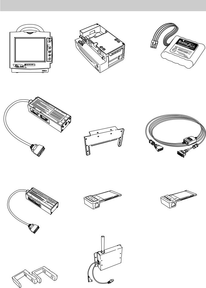
Bedside Monitor
BSM-2300
Interface for connecting a display and external instruments (option)
QI-231P
Interface for connecting a display and an external instrument (option)
QI-236P
Hooks (option)
DZ-230P
1.4
Recorder Module (option)
WS-231P
Adapter for attaching QI-231P interface (option) DI-231P
Network Card (option)
QI-101P
Wireless LAN Station (option)
QI-210P
Battery pack (option) 10HR-4/3FAUC-NK
Interface for connecting Oridion Microcap (option) QI-235P
Network Printer Card (option)
QI-111P
Cart (option)
KC-013P
BSM-2300 RGB cable (option) YS-076P2 (10 m)
YS-080P2 (2 m)
Connection cable for optional units YJ-231P
Operator’s Manual BSM-2300A

1. GENERAL
Multigas unit (option)
AG-920R
|
Operator’s Manual BSM-2300A |
1.5 |
1. GENERAL
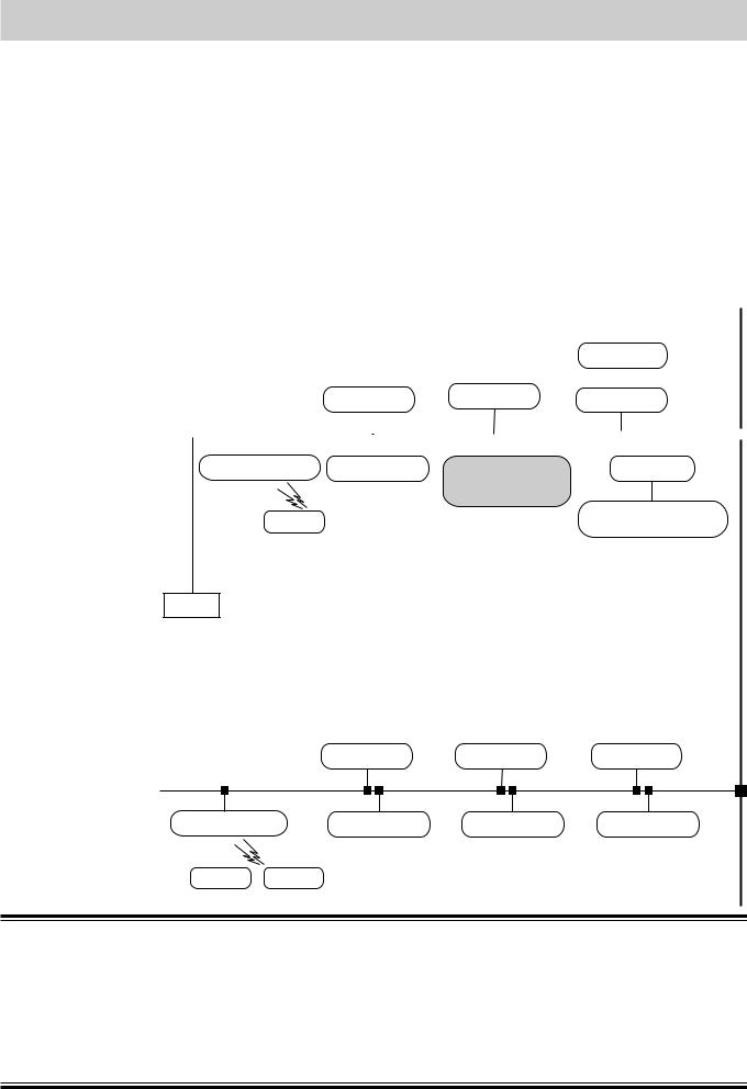
Network Composition
In a central monitor network, on a central monitor, you can see data of any bed in the network.
The data that can be displayed on the bedside monitor or central monitor depends on the type of bedside or central monitor used.
The number of central monitors and bedside monitors that can be connected to a central monitor network and the network communication method depend on the type of monitor used. For details, refer to the Network and System Installation Guide.
Central monitors
|
Network group |
CNS-9300 series |
CNS-9300 series |
Bedside |
monitors |
||||||||||||||||||||||
|
CNS-9701 |
CNS-9701 |
CNS-9300 series |
||||||||||||||||||||||||
|
e.g. ICU |
||||||||||||||||||||||||||
|
Central |
monitor |
Central monitor |
Central |
monitor |
||||||||||||||||||||||
|
Multiple patient receiver |
Bedside monitor |
Bedside monitor |
|
|
ORG-9200 |
BSM-5100 series |
BSM-2300 |
|
|
ORG-9700 |
|||
|
BSM-4100 series |
|||
|
BSM-2300 series |
|||
|
Transmitter |
BSM-1100 series |
Bedside monitors/Transmitters
Printer
|
Network group |
||
|
e.g. CCU |
Central monitor |
Central monitor |
Interface
QI-910R
Bedside monitor Multi-patient receiver
BSM-8000 series
ORG-8200
Central monitor
|
Multiple patient receiver |
Bedside monitor |
Bedside monitor |
Bedside monitor |
Transmitter Transmitter
WARNING
•Install the printer and hubs outside the patient environment. If they are installed inside the patient environment, the patient or operator may receive electrical shock.
•Check the software version number of the monitor before connecting it to the network. Different software versions have different communication methods. When there is more than one communication method in the network, communication may malfunction.
|
1.6 |
Operator’s Manual BSM-2300A |
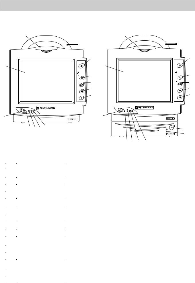
1. GENERAL
Panel Description
Front Panel
|
1 |
1 |
||
|
2 |
2 |
||
|
3 |
SILENCE |
3 |
|
|
SILENCE |
|||
|
ALARMS |
ALARMS |
||
|
13 |
13 |
||
|
NIBP |
NIBP |
||
|
4 |
4 |
||
|
INTERVAL |
INTERVAL |
||
|
START/STOP |
5 |
START/STOP |
5 |
|
MENU |
6 |
MENU |
6 |
|
HOME |
7 |
HOME |
7 |
|
8 |
8 |
||||||
|
9 10 11 12 |
14 |
||||||
|
15 |
|||||||
|
Without optional WS-231P recorder module |
10 11 |
12 |
|||||
|
9 |
|||||||
|
With optional WS-231P recorder module |
|||||||
|
No. |
Name |
Description |
|||||
|
1 |
Alarm indicator |
Red or yellow lamp blinks according to the alarm settings. Green lamp blinks |
|||||
|
in synchronization with the patient’s QRS. |
|||||||
|
2 |
Handle |
For carrying the monitor. |
|||||
|
3 |
SILENCE ALARMS key |
Silences the alarm sound. |
|||||
|
4 |
NIBP INTERVAL key |
Selects NIBP measurement mode. Pressing this key changes the mode. |
|||||
|
5 |
NIBP START/STOP key |
Starts NIBP measurement in selected mode. Pressing the key during |
|||||
|
measurement stops measurement. |
|||||||
|
6 |
MENU key |
Displays the MENU window. |
|||||
|
7 |
HOME key |
Closes any opened window and displays the monitoring screen. |
|||||
|
8 |
Power switch |
Press and hold for more than one second to turn the monitor power on or off. |
|||||
|
9 |
Power lamp |
Lights when the monitor power is turned on. |
|||||
|
10 |
AC power lamp |
Lights when the power cord is connected between the AC SOURCE socket |
|||||
|
and AC outlet. |
|||||||
|
11 |
Battery power lamp |
Lights when operating on the battery power. |
|||||
|
12 |
Battery charging lamp |
Lights or slowly blinks when charging. |
|||||
|
13 |
Touch screen |
Displays monitoring data. Touching a key or data on the screen changes |
|||||
|
displaying screen and settings. |
|||||||
|
14 |
Record key |
Press to start or stop recording. |
|||||
|
15 |
Out of paper lamp |
Blinks when out of paper. Lights when recorder door is open. |
|||||
|
Operator’s Manual BSM-2300A |
1.7 |
![]()
1. GENERAL
Left Side Panel
BSM-2301/2351
|
Refer to Warning and |
|
|
TEMP socket |
Caution in the «General |
|
Connects to the |
Safety Information» section. |
|
temperature probe |
|
|
cord. |
Multi-parameter socket |
|
Connects to the connection cord of the parameter to |
|
|
be monitored (IBP, CO2 or respiration by |
|
|
thermistor method). The type of parameter is |
|
|
automatically recognized. |
Battery box
For the optional battery pack.
TEMP socket
Connects to the temperature probe cord.
SpO2 socket
Connects to the SpO2 connection cord.
ECG/RESP socket
Connects to the ECG connection cord.
NIBP socket
Connects to the air hose.
Without optional WS-231P recorder module
Refer to Warning and
Caution in the «General
Safety Information» section.
Multi-parameter socket
Connects to the connection cord of the parameter to be monitored (IBP, CO2 or respiration
by thermistor method). The type of parameter is automatically recognized.
 SpO2 socket
Connects to the SpO2 connection cord.
ECG/RESP socket
Connects to the ECG connection cord.
NIBP socket
Connects to the air hose.
Battery box
For the optional battery pack.
With optional WS-231P recorder module
|
1.8 |
Operator’s Manual BSM-2300A |

1. GENERAL
BSM-2304
TEMP socket
Connects to the temperature probe cord.
|
PRESS 1 socket |
NELLCOR |
|
OxiMaxTM |
Connects to the IBP connection cord.
Battery box
For the optional battery pack.
TEMP socket
Connects to the temperature probe cord.
NELLCOR
OxiMaxTM
PRESS 1 socket
Connects to the IBP connection cord.
Refer to Warning and
Caution in the «General
Safety Information» section.
Multi-parameter socket
Connects to the connection cord of the parameter to be monitored (IBP (PRESS 2), CO2 or respiration by thermistor method). The type of parameter is automatically recognized.
SpO2 socket
Connects to the SpO2 connection cord.
ECG/RESP socket
Connects to the ECG connection cord.
NIBP socket
Connects to the air hose.
Without optional WS-231P recorder module
Refer to Warning and
Caution in the «General
Safety Information» section.
Multi-parameter socket
Connects to the connection cord of the parameter to be monitored (IBP (PRESS 2), CO2 or respiration by thermistor method). The type of parameter is automatically recognized.
SpO2 socket
Connects to the SpO2 connection cord.
ECG/RESP socket
Connects to the ECG connection cord.
NIBP socket
Connects to the air hose.
Battery box
For the optional battery pack.
With optional WS-231P recorder module
|
Operator’s Manual BSM-2300A |
1.9 |

1. GENERAL
Right Side Panel
Handle
PC card eject button
PC card slot
For an optional QI-101P network card or QI-111P network printer card.
Equipotential grounding terminal
For an equipotential grounding lead.
AUX socket
For connecting a display monitor or optional unit.
 Fuse holder
 AC SOURCE power cord socket
For the AC power cord.
ZB socket
Not available.
Without optional WS-231P recorder module
Handle
PC card eject button
AUX socket
For connecting a display monitor or optional unit.
PC card slot
For an optional QI-101P network card or QI-111P network printer card.
Equipotential grounding terminal
For an equipotential grounding lead.
 Fuse holder
 AC SOURCE power cord socket
For the AC power cord.
ZB socket
Not available.

 WS-231P recorder module (option)
Paper window
For checking the amount of recording paper.
Recorder door release lever
Pull up the lever to open the recorder door.
With optional WS-231P recorder module
|
1.10 |
Operator’s Manual BSM-2300A |

1. GENERAL
WARNING
Connect the network as specified. Otherwise patient and operator may get electrical shock or other injury. For connecting the network, contact your Nihon Kohden distributor.
CAUTION
Use only the Nihon Kohden card.
WARNING
• For patient safety, equipotential grounding of all instruments must be performed. Consult with a qualified biomedical engineer.
• Only use the provided power cord. Using other power cords may result in electrical shock or other injury to the patient and operator.
CAUTION
When the provided power cord cannot be used, operate the monitor on battery power.
WARNING
Connect only the specified instrument to the socket marked with  by following the specified procedure. Otherwise, electrical leakage current may harm the patient and operator.
CAUTION
When connecting the monitor to other instruments, the connection must comply with IEC 60601-1-1. Refer to “General Requirements for Connecting Medical Electrical System” in Section 19.
|
Operator’s Manual BSM-2300A |
1.11 |

1. GENERAL
Basic Operating Concepts
Screen Displays
Following are the screens and windows available on the Life Scope i and the Life Scope L bedside monitors. For details about the individual screens and windows, see the appropriate section.
The shadow of the previous screen may remain for a few minutes after changing the screen.
Normally, the monitoring screen is displayed. All screens, except for the SYSTEM SETUP screen, return to the monitoring screen when there is no key operation for about 3 minutes.
Monitoring screen
HOME
• The monitoring screen can be displayed anytime by pressing the HOME key on the front panel.
• Displays waveforms and data of the monitoring parameters.
• Touching the patient name displays the PATIENT INFO window for entering patient name.
• Touching the parameter data displays the parameter setting window.
MENU window
MENU
The MENU window can be displayed anytime by pressing the MENU key on the front panel. From the MENU window, you can display any window except the monitoring screen.
|
1.12 |
Operator’s Manual BSM-2300A |

1. GENERAL
Enlarged window
ENLARGED window for displaying enlarged numeric data
Review windows
TREND window for displaying 24 hour trendgraph
LIST window for displaying list of parameter data
ARRHYTH RECALL window for displaying arrhythmia recall file data
|
Operator’s Manual BSM-2300A |
1.13 |

1. GENERAL
ALARM HISTORY window for displaying alarm occurrence
Patient information window
PATIENT INFO window for entering patient name. Stored data can be deleted on this window.
Alarm setting window
VITAL ALARM window for setting vital signs alarm and ARRHYTH ALARM window for setting arrhythmia alarms
Parameter setting windows
For changing parameter monitoring settings
ECG window
|
1.14 |
Operator’s Manual BSM-2300A |

1. GENERAL
INTERBED window
For selecting interbed beds and displaying interbed bed data when the monitor is connected to a network
Setup and other windows
RECORDING window for recording setting
DATE & TIME window for changing date and time, SOUND & BRIGHT window for changing alarm and sync sound volume and screen brightness, DISPLAY window for changing trendgraph display on the monitoring screen and respiration/ CO2 waveform sweep speed, FUNCTION KEY window for assigning a function to a function key and TOUCHKEY OFF window for turning touch screen function off
SLEEP MODE window for turning sleep mode on
|
Operator’s Manual BSM-2300A |
1.15 |

1. GENERAL
SYSTEM SETUP screen
SILENCE
ALARMS
Using Touch Screen Keys
For changing system settings. Displaying the SYSTEM SETUP screen interrupts monitoring.
Any window can be opened and settings can be changed by touching the keys and items on the screen with your finger or the touch pen (option).
Touching the key on the screen displays the window.
|
1.16 |
Operator’s Manual BSM-2300A |

1. GENERAL
Tabs for changing displaying window. The opened window is displayed in light blue.
 Selected item is displayed in light blue
Selectable items or keys are displayed in yellow
 Scroll bar and buttons for scrolling data
The time width of the trendgraph on the monitoring screen can be adjusted by touching the position for the right edge of the trendgraph on the screen.
|
Operator’s Manual BSM-2300A |
1.17 |
![]()
1. GENERAL
Keys on the Front Panel
SILENCE
ALARMS
NIBP
INTERVAL
START/STOP
MENU
HOME
Silences alarm sound
Selects NIBP measurement mode
Starts and stops NIBP measurement
Displays the MENU window
Displays the monitoring screen
Turns the monitor power on or off
Using the MENU Window
Section 7
Section 5
Section 4
Section 6
Section 4
1.18
 Starts and stops recording
(when using optional recorder module)
The MENU window can be displayed anytime by pressing the MENU key on the front panel. From the MENU window, you can display any window except the monitoring screen.
For details on each window, refer to the section specified below.
Section 14
Section 10
Section 11
Section 12
Section 13
|
Section 15 |
|
|
Section 16 |
|
|
Section 6 |
|
|
Section 9 |
|
|
Section 5 |
Section 18 |
|
Section 8 |
Section 4 |
|
Operator’s Manual BSM-2300A |

1. GENERAL
General Safety Information
General
WARNING
•Never use this monitor in the presence of any flammable anesthetic gas, concentrated oxygen or hyperbaric oxygen. Failure to follow this warning may result in explosion.
•Never use the monitor in a high-pressure oxygen medical care tank. Failure to follow this warning may cause explosion or fire.
•When using this monitor with an electrosurgery unit, its return plate and the electrodes for monitoring must be firmly attached to the patient. If the return plate is not attached correctly, it may burn the patient’s skin where the electrodes are attached. Refer to the instruction manual for the ESU.
•When performing MRI tests, remove the electrodes and transducers connected to the patient from this monitor. The heat generated from the induced electromotive force may burn the patient’s skin. For details, refer to the instruction manual for the MRI.
•When performing defibrillation, discharge as far as possible from electrodes and medicine on the chest of the patient. If there is a possibility that the defibrillator paddle could touch electrodes and medicine, remove electrodes and medicine from the patient. If the defibrillator directly contacts these materials, the discharged energy may cause serious electrical burn to the patient.
•Before performing defibrillation, check that the cords and cables of the electrodes and transducers attached to the patient are properly connected to the monitor. Touching the metal parts of disconnected cords and cables may cause serious electrical shock or injury by discharged energy.
•To avoid the risk of serious electrical burn, shock or other injury during defibrillation, all persons must keep clear of the bed and must not touch the patient or any equipment connected to the patient.
•During alarm suspension (the “ALARMS SUSPENDED” or “ALL ALARMS OFF” message displayed), all current alarms are temporarily turned off.
•Before setting ALARMS OFF TYPE, consult the administrator of this monitor in your facility. Before selecting “ALL ALARMS OFF” or “BYPASS”, all operators must thoroughly understand the function of the “ALL ALARMS OFF” key and “BYPASS” key which turn all alarms off for an indefinite period.
•Do not turn all alarms off with the ALL ALARMS OFF key when there is no medical staff around the patient or when the patient is connected to a ventilator.
•Do not turn all alarms off with the BYPASS key when there is no medical staff around the patient.
•When EXIT SLEEP MODE ON ALARM on the SYSTEM SETUP screen is set NO, the bedside monitor alarm cannot be seen or heard on the bedside monitor during sleep mode. Monitor the bedside monitor
|
Operator’s Manual BSM-2300A |
1.19 |

1. GENERAL
alarm on the central monitor or telemetry system. Otherwise, the bedside monitor alarm may be overlooked.
•For arrhythmia monitoring, set ARRHYTHMIA ANALYSIS on the ECG window to ON. Otherwise, there is no sound or indication for arrhythmia alarms.
•When admitting a new patient, check the alarm settings. The alarm settings return to the alarm master settings on the SYSTEM SETUP screen when all data is deleted on the DELETE ALL window or 30 minutes elapse after monitor power off.
CAUTION
•Use only Nihon Kohden specified electrodes, probes, transducers, thermistors and catheters. Otherwise, the maximum performance from the monitor cannot be guaranteed.
•Do not reuse disposable parts.
•Turn off the power of cell telephones, small wireless devices and other devices which produce strong electromagnetic interference. Otherwise, the waveforms and measurements are affected by such interference and the displayed data may be incorrect.
•When admitting a new patient, first delete all data of the previous patient. Otherwise, the data of the previous patient and new patient will be mixed together.
•After the monitor power is turned on, parameter-related alarms do not function until the parameters are monitored (during standby mode).
•Alarm recording is not performed when alarm is suspended or alarm recording is set to off.
•If there is any doubt about the arrhythmia analysis, make the monitor relearn the patient’s VPC. Otherwise, an important arrhythmia maybe overlooked.
•When the upper or lower alarm limit is turned off, there will be no upper or lower alarm for that parameter limit.
•When the “CONNECTOR OFF” message appears on the screen, check that the connection cords are connected to the sockets properly. Patient cannot be monitored and the alarm does not function properly while this message is displayed.
•Do not turn the monitor off when the system check screen is displayed. Otherwise the saved data may be damaged or deleted. If the monitor is turned off during system check, delete all data because the data is not reliable.
•If fluids are accidentally spilled on the monitor, take the bedside monitor out of service and check for damage.
Installation WARNING
• For patient safety, equipotential grounding of all instruments must be
|
1.20 |
Operator’s Manual BSM-2300A |

1. GENERAL
performed. Consult with a qualified biomedical engineer.
•Only use the provided power cord. Using other power cords may result in electrical shock or other injury to the patient and operator.
•When the provided power cord cannot be used or when equipotential grounding is doubtful (such as in poor grounding facility), operate the monitor on battery power.
•Connect only the specified instrument to the socket marked with  by following the specified procedure. Otherwise, electrical leakage current may harm the patient and operator.
CAUTION
•When connecting the monitor to other instruments, the connection must comply with IEC 60601-1-1. Refer to “General Requirements for Connecting Medical Electrical System” in Section 19.
•Disconnect the power cord from the AC socket before connecting the instruments.
•Use only the KC-013P cart for the BSM-2300 bedside monitor. If another cart is used, it may tip over or the monitor may fall off.
•Avoid locations where the monitor and system may be sprinkled with water or chemical solutions. Otherwise the monitor and system may be damaged.
•When not using the KC-013P cart, make sure that the monitor is placed and fastened so that it does not tip over.
•Install the monitor and ESU appropriately and perform equipotential grounding. Otherwise, noise from the ESU may interfere with the ECG and ECG monitoring may not be performed properly.
•At the monitor on, check that one “bong” sounds and the red alarm lamp, yellow lamp and green lamp blink once to show that the alarm functions properly.
Also read the warning and caution in “Selecting a Suitable Location” in Section 2.
Using QI-231P/236P
Interface
WARNING
If the display does not have an equipotential ground terminal and the bedside monitor and display cannot be equipotentially grounded, make sure that the display is grounded to the same AC outlet as the bedside monitor. Always perform equipotential grounding as specified in IEC 60601-1-1 when required.
|
CAUTION |
|
|
• Before connecting instruments, make sure that the power is turned |
|
|
off. Otherwise electrical current may harm the patient and operator. |
|
|
Operator’s Manual BSM-2300A |
1.21 |

1. GENERAL
However, when using the TRIG output, before connecting the instrument to the interface, connect the interface cable to the monitor, display the monitoring screen on the monitor and check that the TRIG LED on the interface is lit. (Only QI-231P interface has the TRIG LED.)
•Keep the interface and cable out of the way. Otherwise people may trip over it, causing the cable to break or the bedside monitor to fall and injure the patient and operator.
•When using the output signal from the interface as the synchronization signal for other equipment such as IABP (intraaortic balloon pump), or defibrillator:
·Set the timing of the other equipment by checking the waveform on the screen of the equipment.
·Check the condition of the bedside monitor at all times. The output signal may become unstable.
·Check that the delay time of the output signal (QRS sync 100 ms (QI-231P) / 20 ms (QI-236P) maximum, ECG analog 20 ms maximum) is within the range of the connected equipment.
·Do not use the QRS sync signal as the synchronization signal for a defibrillator.
•Only use the DI-231P adapter for attaching the interface to the monitor.
Using DZ-230P Hooks
CAUTION
•Use the hooks only for hooking the BSM-2300 series bedside monitors onto a board.
•Do not carry the monitor by the hooks.
•Hook the monitor onto a board which can support the weight of the monitor.
•To prevent the monitor from falling off, periodically check that the hooks are attached to the monitor properly.
•Do not put weight on the hooks and monitor.
•Make sure that both hooks are properly hooked onto the board.
•When moving a bed with a monitor hooked to it, make sure that the monitor does not fall off.
Network
WARNING
•Install the printer and hubs outside the patient environment. If they are installed inside the patient environment, the patient or operator may receive electrical shock.
|
1.22 |
Operator’s Manual BSM-2300A |

1. GENERAL
•Connect the network as specified. Otherwise patient and operator may get electrical shock or other injury. For connecting the network, contact your Nihon Kohden distributor.
•Do not use the damaged network cable. Otherwise patient or operator may get an electrical shock when the damaged part is touched.
•Check the software version number of the monitor before connecting it to the network. Different software versions have different communication methods. When there is more than one communication method in the network, communication may malfunction.
CAUTION
•The network must be managed by the network administrator. Make sure that each monitor in the network has a different IP address. Otherwise, data communication cannot be performed properly. When adding a unit to an already operating network, set the IP address on the monitor before connecting the monitor to the network.
•Use only the Nihon Kohden network card.
•Do not push in the network cable with too much force. Otherwise the network card or bedside monitor may get damaged.
•When the monitor is connected to a central monitor network, set the Bed Name (Bed ID) and Group Name on the monitor. Otherwise, the default settings are used for the bed name and group name and the bed may be incorrectly identified on the central monitor.
Battery
WARNING
•Keep the battery pack away from fire. The battery pack may explode.
•Do not heat the battery pack. The battery pack may explode.
•Never short-circuit the + and – terminals on the battery pack with a wire or store the battery pack with metals such as necklace or hair pins. The battery pack may short-circuit, causing the substance inside the battery to leak or explode.
•Never disassemble or modify the battery pack. Never damage or directly solder the sheath tube. The battery pack short-circuits, the electrolyte comes out and the battery pack explodes.
•Do not subject the battery pack to a strong mechanical shock. The battery may leak or explode.
•Do not use a battery which is damaged, such as from falling. There is a gas discharge valve inside the battery and if this valve is damaged, the gas cannot be discharged, causing the battery to explode.
•Only use the battery pack on the specified instrument. If the battery
|
Operator’s Manual BSM-2300A |
1.23 |

1. GENERAL
is used on an unspecified instrument, large current may flow, causing the battery to explode.
•If the battery pack is damaged and the substance inside the battery (alkaline liquid) contacts the eyes or skin, wash immediately and thoroughly with water and see your physician. Never rub your eyes, otherwise you may lose your eyesight.
•The battery pack has + and – polarity. Make sure that the battery is installed with the correct polarity direction. Otherwise, the substance inside the battery may leak and explode.
•Do not connect the battery pack to an AC outlet or lighter socket in a car. The battery may explode.
•Do not immerse the battery pack in water or seawater. The battery will rust and may heat up.
•Never use a battery pack which is damaged, discolored or has leakage. A damaged battery may explode if used.
•Do not leave the battery for more than two years unused. The battery may leak.
CAUTION
•Do not expose the battery pack to direct sunlight or leave in a high temperature place. The lifetime of the battery pack may be shortened or the substance inside the battery pack may leak.
•Do not leave a used battery pack for a long period of time (more than one year). The substance inside the battery may leak.
•The battery pack must be replaced by qualified service personnel.
•Keep the battery pack away from children.
•Before disposing of the battery, check with your local solid waste officials for details in your area for recycling options or proper disposal. The battery is recycleable. At the end of its useful life, under various state and local laws, it may be illegal to dispose of this battery into the municipal waste stream.
ECG Monitoring
WARNING
Interaction Between Minute Ventilation Rate-Adaptive Pacemakers and
Cardiac Monitoring and Diagnostic Equipment*
The bioelectric impedance measurement sensor of a minute ventilation rate-adaptive implantable pacemaker may be affected by cardiac monitoring and diagnostic equipment which is connected to the same patient. If this occurs, the pacemaker may pace at its maximum rate and give incorrect data to the monitor or diagnostic equipment. If this occurs, disconnect the monitor or diagnostic equipment from the patient or change the setting on the pacemaker by referring to the
|
1.24 |
Operator’s Manual BSM-2300A |

1. GENERAL
pacemaker’s manual. For more details, contact your pacemaker
distributor or Nihon Kohden distributor.
*Minute ventilation is sensed in rate-adaptive pacemakers by a technology known as bioelectric impedance measurement (BIM). Many medical devices in addition to pacemakers use this technology. When one of these devices is used on a patient with an active, minute ventilation rate-adaptive pacemaker, the pacemaker may erroneously interpret the mixture of BIM signals created in the patient, resulting in an elevated pacing rate.
For more information, see the FDA web site. http://www.fda.gov/cdrh/safety.html
WARNING
•When using a defibrillator together with the monitor, use Ag/AgCl electrodes. Other types of electrodes, stainless steel in particular, will adversely affect the ECG waveform by slowing the baseline recovery on the monitor and result in no monitoring immediately following defibrillation.
•False heart rate indicators may occur with certain pacemakers because of electrical overshoots.
•Pacemaker patients can only be monitored when the pace program is activated.
•Keep pacemaker patients under close observation. The pacemaker rate may be counted during cardiac arrest and certain arrhythmias. Do not rely only on the monitor.
•For arrhythmia monitoring, set ARRHYTHMIA ANALYSIS on the ECG window to ON. Otherwise, there is no sound or indication for arrhythmia alarms.
CAUTION
•Use only Nihon Kohden products and specified parts and accessories. When other type of electrodes are used, the “CHECK ELECTRODES” message may be displayed and monitoring may stop.
•Do not reuse disposable electrodes.
•If the contact is bad even before the expiration date printed on the package, replace the electrode with a new one.
•When the “CHECK ELECTRODES” message is displayed, ECG is not monitored properly. Check the electrode, electrode leads and connection cord, and if necessary, replace it with a new one.
•When using the monitor with an ESU, locate the monitor and ESU following the description in “Use with an Electrosurgical Unit” in Section 10 and ground the instruments properly. Otherwise noise from the ESU may interfere with the ECG and the heart rate and arrhythmia analysis may be incorrect.
•At the start of ECG monitoring, check that the dominant QRS is
|
Operator’s Manual BSM-2300A |
1.25 |

1. GENERAL
appropriate. Otherwise arrhythmia monitoring may be inaccurate.
•If there is any doubt about the arrhythmia analysis, make the monitor relearn the patient’s VPC and check that the dominant QRS is appropriate. Otherwise, arrhythmia monitoring may not be accurate.
•Changing the dominant QRS must be performed under the physician’s instructions.
•When the alarm is turned OFF for an arrhythmia, there will be no alarm for that arrhythmia type.
•Turn the pacing spike detection to On when monitoring a pacemaker patient. Otherwise QRS and pacemaker spike may not be distinguished and pacemaker failure may not be recognized.
Respiration Monitoring
WARNING
Interaction Between Minute Ventilation Rate-Adaptive Pacemakers and
Cardiac Monitoring and Diagnostic Equipment*
The bioelectric impedance measurement sensor of a minute ventilation rate-adaptive implantable pacemaker may be affected by cardiac monitoring and diagnostic equipment which is connected to the same patient. If this occurs, the pacemaker may pace at its maximum rate and give incorrect data to the monitor or diagnostic equipment. If this occurs, disconnect the monitor or diagnostic equipment from the patient or change the setting on the pacemaker by referring to the pacemaker’s manual. For more details, contact your pacemaker distributor or Nihon Kohden distributor.
*Minute ventilation is sensed in rate-adaptive pacemakers by a technology known as bioelectric impedance measurement (BIM). Many medical devices in addition to pacemakers use this technology. When one of these devices is used on a patient with an active, minute ventilation rate-adaptive pacemaker, the pacemaker may erroneously interpret the mixture of BIM signals created in the patient, resulting in an elevated pacing rate.
For more information, see the FDA web site. http://www.fda.gov/cdrh/safety.html
SpO2 Monitoring
WARNING
•Measurement may be incorrect in the following cases.
·When the patient’s carboxyhemoglobin or methemoglobin increases abnormally.
·When dye is injected in the blood.
·When using an electrical surgery unit.
|
1.26 |
Operator’s Manual BSM-2300A |

1. GENERAL
·During CPR.
·When there is body movement.
·When there is vibration.
·When measuring at a site with venous pulse.
·When the pulse wave is small (insufficient peripheral circulation).
·When using an IABP (intra-aortic balloon pump).
•Check the circulation condition by observing the skin color of the measuring site and pulse waveform. Change the measuring site every 8 hours for disposable probes and every 4 hours for reusable probes. The skin temperature may increase at the attached site by 2 or 3°C (4 or 5°F) and cause a burn or pressure necrosis. When using the probe on the following patients, take extreme care and change the measurement site more frequently according to symptoms and degree.
·A patient with a fever
·A patient with peripheral circulation insufficiency
·Neonate or low birth weight infant with delicate skin
•When using the TL-201T finger probe, do not fasten the probe and cable to the finger by wrapping with tape. This may cause burn, congestion or pressure necrosis from poor blood circulation.
•When using probes other than the TL-201T finger probe, to avoid poor circulation, do not wrap the tape too tight. Check the blood circulation condition by observing the skin color and congestion at the skin peripheral to the probe attachment site. Even for short-term monitoring, there may be burn or pressure necrosis from poor blood circulation, especially on neonates or low birth weight infants whose skin is delicate. Accurate measurement cannot be performed on a site with poor peripheral circulation.
•When not monitoring SpO2, disconnect the SpO2 connection cord from the bedside monitor. Otherwise, noise may interfere from the probe sensor and displays incorrect data on the screen.
•Do not use the probe during MRI examination because it may cause skinburn on the probe attachment area. For details, follow the MRI operator’s manual.
CAUTION
•When using Nellcor probes, read the instructions provided with the probe.
•When using Nellcor probes, do not touch the SpO2 socket pins on the monitor with your finger when connecting or disconnecting the connection cord from the monitor. The monitor may malfunction or get damaged.
•Turn off the power of cell telephones, small wireless devices and other devices which produce strong electromagnetic interference. Otherwise, the waveforms and measurements are affected by such interference and the displayed data may be incorrect.
•Only use the specified probes. Otherwise SpO2 cannot be monitored properly.
|
Operator’s Manual BSM-2300A |
1.27 |
 Loading…
|
Параметры |
Требования / диапазон |
Соответствие |
|
Цветной ЖК дисплей: |
Наличие |
Соответствие |
|
Тип: цветной жидкокристаллический TFT |
Наличие |
Соответствие |
|
Размер экрана: диагональ не менее 21 см (8,4 inch) |
Наличие |
Соответствие |
|
Полностью сенсорный дисплей |
Наличие |
Соответствие |
|
Запоминание личных данных пациента |
Наличие |
Соответствие |
|
Возможность настройки параметров различных групп пациентов: взрослые, дети, новорожденные |
Наличие |
Соответствие |
|
Режим демо/помощь |
Наличие |
Соответствие |
|
Режим отображения кривой: |
Наличие |
Соответствие |
|
— безинерционный подвижный |
Наличие |
Соответствие |
|
— безинерционный фиксированный |
Наличие |
Соответствие |
|
Режим увеличенного отображения данных |
Наличие |
Соответствие |
|
Разрешающая способность не менее 800х600 точек |
Наличие |
Соответствие |
|
Одновременное отображение на экране, не менее 5 кривых (12-ти цветов), в т.ч.: |
Наличие |
Соответствие |
|
— ЭКГ – 2; |
Наличие |
Соответствие |
|
— Дыхание – 1; |
Наличие |
Соответствие |
|
— IBP или CO2 – 1. |
Наличие |
Соответствие |
|
— SpO2 – 1; |
Наличие |
Соответствие |
|
Замораживание кривых |
Наличие |
Соответствие |
|
Отображаемые числовые данные: |
Наличие |
Соответствие |
|
— ЧСС |
Наличие |
Соответствие |
|
— частота VPC |
Наличие |
Соответствие |
|
— уровень ST |
Наличие |
Соответствие |
|
— частота дыхания |
Наличие |
Соответствие |
|
— IBP (систолическое, диастолическое, среднее) |
Наличие |
Соответствие |
|
— NIBP (систолическое, диастолическое, среднее) |
Наличие |
Соответствие |
|
— SPO2 |
Наличие |
Соответствие |
|
— частота пульса |
Наличие |
Соответствие |
|
— температура |
Наличие |
Соответствие |
|
— ETCO2 |
Наличие |
Соответствие |
|
Возможность отображения оксикардиореспирограммы (OCRG – режим) для неонатологии |
Наличие |
Соответствие |
|
Скорость развертки: 25 мм/с, 50 мм/с (малая скорость дыхания и СО2: 1,56 мм/с) |
Наличие |
Соответствие |
|
Количество цветов отображения кривых: 12 цветов (возможность выбора) |
Наличие |
Соответствие |
|
Метки синхронизации: Синхрометки ЧСС, частоты пульса, дыхания |
Наличие |
Соответствие |
|
Количество цветов отображения чисел: 12 цветов (возможность выбора); |
Наличие |
Соответствие |
|
Запоминание: |
||
|
графическое отображение 1,2, 4, 8 или 24 часов трендов каждого параметра; |
Наличие |
Соответствие |
|
«Длинные» 24-часовые тренды с разрешением до 5-минут и «короткие» 8-часовые тренды с разрешением до 2 минут |
Наличие |
Соответствие |
|
Запоминание по тревоге или вручную до 16 клинических событий |
Наличие |
Соответствие |
|
Длительность не менее 5 сек. |
Наличие |
Соответствие |
|
Наличие мультипараметрических коннекторов |
Наличие |
не менее 1 |
|
Наличие не менее 3-х програмируемых функциональных кнопок на экране |
Наличие |
Соответствие |
|
Возможность подключения модуля измерения капнометрии в боковом потоке |
Наличие |
|
|
Возможность объединения в мониторную сеть с центральной станцией: |
Наличие |
Соответствие(при включении в комплект монитора сетевой карты) |
|
Возможность подключения дублирующего дисплея через стандартный VGA интерфейс |
Наличие |
Соответствие |
|
Возможность подключения модуля измерения анестезиологических газов и летучих анестетиков |
Наличие |
Соответствие |
|
Возможность подключения модуля измерения индекса глубины анестезии (BIS-индекс) |
Наличие |
Соответствие |
|
BIS — индекс угасания электроэнцефалографической активности (биспектральный индекс) Показатель, получаемый при множественном дискриминационном анализе, как суммарная биспектральная характеристика (частота, мощность и фаза) на всем частотном диапазоне. |
Возможные значения 0 — 100 |
Соответствие |
|
Отображение BIS в числовом значении |
наличие |
Соответствие |
|
Отображение BIS в виде тренда |
наличие |
Соответствие |
|
Период обновления значений BIS ,не менее |
1 с |
Соответствие |
|
Период обновления тренда BIS, не менее |
10 с |
Соответствие |
|
Индекс качества сигнала (SQI)Показатель качества сигнала, передаваемого по ЭЭГ-каналу, подсчитываемый на основании данных импеданса, выраженности помех и других переменных. |
Возможные значения от 0 — до 100 |
Соответствие |
|
ЭЭГ–отображение кривой электроэнцефалограммы в реальном времени |
Наличие |
Соответствие |
|
Скорость развертки ЭЭГ |
от 15 до 30 мм/с |
Соответствие |
|
Фильтры ЭЭГ, возможность включения (2-10Гц), отключения фильтров (0,25-100)Гц |
Наличие |
Соответствие |
|
Длительность эпохи ЭЭГ не менее |
2 с |
Соответствие |
|
Удаление помех |
автоматически |
Соответствие |
|
Коэффициент подавления (SR) Процент времени в течение последних 63 секунд, когда ЭЭГ-сигнал считался подавленным. |
Возможные значения от 0…до 100% |
Соответствие |
|
Показатель частоты 95% мощности сигнала (SEF) Показатель отражает частоту, ниже которой лежит 95% общей мощности, а выше – 5%. |
Возможные значения от 0,5…до 30 Гц |
Соответствие |
|
EMG — показания электромиографии фронтальной мышцы. Суммарная мощность EMG (дБ) в диапазоне 70-110 Гц, представляется в виде гистограммы и тренда |
от 30 – до 80 дБ (тренд) от 30 –до 55 дБ (гистограмма) |
Соответствие |
|
Журнал значений BIS |
Наличие |
Соответствие |
|
Выбор пользователем типов данных для представления на экране монитора |
Наличие |
Соответствие |
|
Установка пользователем пределов сигналов тревоги (визуальных / звуковых) |
Наличие |
Соответствие |
|
Возможность съема ЭЭГ-сигнала с пациента при помощи одноразовых или многоразовых налобных сенсоров |
Наличие |
Соответствие |
|
Самоконтроль работы прибора |
Наличие |
Соответствие |
|
Автоматическое тестирование датчиков сенсора ЭЭГ при подключению к прибору |
Наличие |
Соответствие |
|
Сигнал тревоги при отсоединении электродов от пациента |
Наличие |
Соответствие |
|
Сообщения системы об ошибках оборудования, ошибках соединений, угрожающих состояниях пациента |
Отображение на экране монитора и сопровождение звуковым сигналом |
Соответствие |
|
Диапазон амплитуд регистрируемых сигналов |
до ±1000 мкВ |
Соответствие |
|
Встроенная память |
Наличие |
Соответствие |
|
Возможность подключения пульсоксиметров других производителей: |
Наличие |
Соответствие |
|
Возможность использования при наличии кабеля |
Наличие |
Соответствие |
|
Просмотр и распечатка сохраненных данных тренда во время проведения мониторинга |
Наличие |
Соответствие |
|
Звук |
Наличие |
Соответствие |
|
Типы звуков: |
Наличие |
Соответствие |
|
— Тревога |
Наличие |
Соответствие |
|
— синхронизация |
Наличие |
Соответствие |
|
— нажатие кнопок |
Наличие |
Соответствие |
|
Звуковая тревога: 3 типа |
Наличие |
Соответствие |
|
Звук синхронизации: Переменный тон для IBP и SPO2 |
Наличие |
Соответствие |
|
Возможность установки границ звукового сигнала с сенсорного дисплея |
||
|
Тревога |
||
|
Визуальное оповещение |
Наличие |
Соответствие |
|
Звуковое оповещение |
Наличие |
Соответствие |
|
Идентификация тревоги мониторируемого параметра |
Наличие |
Соответствие |
|
Возможность задания верхних и нижних сигналов тревог всех мониторируемых параметров непосредственно с сенсорного дисплея |
Наличие |
Соответствие |
|
Элементы тревоги: |
||
|
Верхняя/нижняя границы тревоги, тревога апноэ, аритмии, отсоединения разъемов, шума NOISE, отсоединения электродов, определения кривой пульса, отсоединения датчиков, контроля манжеты/шланга, сенсора, разряда батареи, условий окружающей среды. |
Наличие |
Соответствие |
|
Виды тревоги: Критическое состояние, Предостережение об опасности, Внимание. |
Наличие |
Соответствие |
|
Отключение тревоги: На 1 или 2 мин. |
Наличие |
Соответствие |
|
Возможность установки границ сигналов тревоги непосредственно с сенсорного дисплея |
Соответствие |
|
|
ЭКГ |
||
|
Допустимое отклонение потенциала электрода: ± 500 мВ |
Наличие |
Соответствие |
|
Входной динамический диапазон: ± 5 мВ |
Наличие |
Соответствие |
|
Внутренние шумы: не более 30µ Vp-p (относительно входного сигнала) |
Наличие |
Соответствие |
|
Коэффициент подавления в обычном режиме: ≥95dB |
Наличие |
Соответствие |
|
Входное сопротивление: ≥5МΩ (при 10 Гц) |
Наличие |
Соответствие |
|
Диапазон расчета ЧСС: 1 – 300 уд./мин. |
Наличие |
Соответствие |
|
Цикл обновления отображения ЧСС: Каждые 3 с или при генерировании тревоги |
Наличие |
Соответствие |
|
Анализ аритмии: |
Наличие |
Соответствие |
|
Метод анализа: сравнение по образцу |
Наличие |
Соответствие |
|
Число каналов: Не менее одного |
Наличие |
Соответствие |
|
Подсчет частоты VPC: 0 – 99 VPC/мин. |
Наличие |
Соответствие |
|
Тревоги аритмии, не менее |
23 типа |
Соответствие |
|
ASYSTOLE (асистолия) |
наличие |
Соответствие |
|
VT (желудочковая тахикардия) |
наличие |
Соответствие |
|
VF(желудочковая фибрилляция) |
наличие |
Соответствие |
|
VPC RUN (серия экстрасистол) |
наличие |
Соответствие |
|
COUPLET (парная экстрасистола) |
наличие |
Соответствие |
|
EARLY VPC (ранняя экстрасистола) |
наличие |
Соответствие |
|
BIGEMINY (бигеминия) |
наличие |
Соответствие |
|
VPC (экстрасистола) |
наличие |
Соответствие |
|
FREQ VPC (частые экстрасистолы) |
наличие |
Соответствие |
|
TACHYCARDIA (тахикардия) |
наличие |
Соответствие |
|
BRADYCARDIA (брадикардия) |
наличие |
Соответствие |
|
V BRADY (желудочковая брадикардия) |
наличие |
Соответствие |
|
EXT TACHY (критическая тахикардия) |
наличие |
Соответствие |
|
EXT BRADY (критическая брадикардия) |
наличие |
Соответствие |
|
SV TACHY (суправентрикулярная тахикардия) |
наличие |
Соответствие |
|
MULTIFORM (две экстрасистолы различной формы в течение 3 минут) |
наличие |
Соответствие |
|
V RHYTHM (желудочковый ритм) |
наличие |
Соответствие |
|
PAUSE (нет комплекса QRS в течение 1-3 сек) |
наличие |
Соответствие |
|
TRIGEMINY (тригеминия) |
наличие |
Соответствие |
|
IRREGULAR RR (нерегулярный RR интервал) |
наличие |
Соответствие |
|
PACER NON-CAPTURE (QRS комплекс не обнаружен в пределах заданного интервала времени) |
наличие |
Соответствие |
|
PROLONGED RR (RR интервал длиннее доминантного) |
наличие |
Соответствие |
|
NO PACER PULSE (не обнаружен QRS комплекс в пределах предела брадикардии) |
наличие |
Соответствие |
|
Воспроизведение аритмии: |
Наличие |
Соответствие |
|
Число файлов воспроизведения: не менее 16 |
Наличие |
Соответствие |
|
Время записи на файл: не менее 8 сек. |
Наличие |
Соответствие |
|
Защита от дефибриляции: Защита входа ЭКГ от 400 J |
Наличие |
Соответствие |
|
Отведения: |
Наличие |
Соответствие |
|
по 3-электродам: I, II, III |
Наличие |
Соответствие |
|
по 6-электродам: I, II, III, AVr, aVL, aVF, V4, V5 |
Наличие |
Соответствие |
|
Возможность измерения ST |
Наличие |
Соответствие |
|
Возможность установки границ тревоги по сегменту ST: + 2.0 mV |
Наличие |
Соответствие |
|
Возможность установки параметров ЭКГ и границ тревоги непосредственно с сенсорного дисплея |
Наличие |
Соответствие |
|
Возможность анализа аритмии на центральной станции 9ххх |
Наличие |
Соответствие |
|
Дыхание |
||
|
Метод измерения: Импедансный, термисторный |
Наличие |
Соответствие |
|
Возможность изменения отведений при импедансном методе измерения |
Наличие |
Соответствие |
|
Диапазон расчета частоты дыхания: 0 – 150 дых./мин. Апноэ, 5 – 40 с |
Наличие |
Соответствие |
|
Точность: ± 2 дых./мин. |
Наличие |
Соответствие |
|
Защита от дефибрилятора: Защита входа дыхания от разряда до 400 Дж |
Наличие |
Соответствие |
|
Цикл отображения частоты дыхания: Каждые 3 сек. или при подаче тревоги |
Наличие |
Соответствие |
|
Возможность установки параметров дыхания и границ тревоги непосредственно с сенсорного дисплея |
Наличие |
Соответствие |
|
Принудительное шумоподавление в диагностике апноэ у новорожденных в режиме (NICU) |
Наличие |
Соответствие |
|
SpO2 |
||
|
Методика измерения-BluePro® |
Наличие |
Соответствие |
|
Диапазон измерения: 1 – 100 % |
Наличие |
Соответствие |
|
Диапазон измерения пульса: 30 – 300 уд./мин. |
Наличие |
Соответствие |
|
Точность SpO2: ±2 ед. (от 80% до 100%), ±3 ед. (от 50% до 80%) |
Наличие |
Соответствие |
|
Цикл обновления отображения частоты пульса: Каждые 3 с или при подаче тревоги. |
Наличие |
Соответствие |
|
Чувствительность кривой: х1/8, х1/4, х1/2, х1, х2, х4, х8 |
Наличие |
Соответствие |
|
Возможность установки параметров пульоксиметрии и границ тревоги непосредственно с сенсорного дисплея |
Наличие |
Соответствие |
|
Неинвазивное измерение кровяного давления (НИАД) |
||
|
Метод измерения: Осциллометрический |
Наличие |
Соответствие |
|
Диапазон отображения давления: от 0 – до +300 мм рт. ст. |
Наличие |
Соответствие |
|
Время накачки манжеты: |
Наличие |
Соответствие |
|
Взрослые и дети – не более 7 с |
Наличие |
Соответствие |
|
Новорожденные – не более 5 с |
Наличие |
Соответствие |
|
Ограничитель максимальной величины давления накачки манжеты: |
Наличие |
Соответствие |
|
Взрослые/дети – до 300 мм рт. ст. |
Наличие |
Соответствие |
|
Новорожденные до 150 мм рт. ст. |
Наличие |
Соответствие |
|
Ограничитель времени накачки манжеты: |
Наличие |
Соответствие |
|
Взрослые/дети – до 180 с |
Наличие |
Соответствие |
|
Новорожденные –до 90 с |
Наличие |
Соответствие |
|
Режим измерений: |
Наличие |
Соответствие |
|
— Ручной, |
Наличие |
Соответствие |
|
— Непрерывный, |
Наличие |
Соответствие |
|
периодический (интервалы: не менее 2, 2.5, 5, 10, 15, 30 мин., 1, 2, 4, 8 ч., PWTT) |
Наличие |
Соответствие |
|
Многоразовые манжеты специальной двойной конструкции для предотвращения повреждения кожи пациента при длительном или постоянном измерении НИАД, не содержат латекс. |
Наличие |
Соответствие |
|
Функция триггерного измерения неинвазивного кровяного давления (по транзисторному времени пульсовой волны) |
Наличие |
Соответствие |
|
Возможность установки параметров NIBP и границ тревоги непосредственно с сенсорного дисплея |
Наличие |
Соответствие |
|
Инвазивное измерение кровяного давления (IBP) |
||
|
Встроенный модуль измерения ИАД-1 канал |
Наличие |
Соответствие |
|
Диапазон измерения давления: от -50 – до +300 мм.рт.ст. |
Наличие |
Соответствие |
|
Точность измерения: |
Наличие |
Соответствие |
|
± 1 мм.рт.ст. ± 1digit. (от -50 мм.рт.ст. до 100 мм.рт.ст.) |
Наличие |
Соответствие |
|
± 1 % ± 1digit. (от 100 мм.рт.ст. до 300 мм.рт.ст.) |
Наличие |
Соответствие |
|
Возможность установки параметров IBP и границ тревоги непосредственно с сенсорного дисплея |
Наличие |
Соответствие |
|
Температура |
||
|
Встроенный модуль термометрии |
Наличие |
Соответствие |
|
Диапазон измерения: 0 – 450С |
Наличие |
Соответствие |
|
Точность измерения: |
Наличие |
Соответствие |
|
±0.10С (от 25°Сдо 45°С) |
Наличие |
Соответствие |
|
±0.20С (от 0°С до 25°С) |
Наличие |
Соответствие |
|
Цикл обновления: Каждые 3 с |
Наличие |
Соответствие |
|
Возможность установки параметров температуры и границ тревоги непосредственно с сенсорного дисплея |
Наличие |
Соответствие |
|
Давление выдыхаемого углекислого газа |
||
|
Встроенный модуль капнометрии |
Наличие |
Соответствие |
|
Метод измерения: По основному потоку |
Наличие |
Соответствие (при включении в комплект монитора набора капнметрии по данной методике) |
|
Метод измерения : По боковому потоку |
Возможность |
|
|
Капнометрия у интубированных и неинтубированных пациентов |
Возможность |
|
|
Возможность проведения капнометрии по методике CapOne® |
наличие |
Соответствие |
|
Диапазон измерения: 0 – 100 мм.рт.ст. |
Наличие |
Соответствие |
|
Время разогрева: 5 с |
Наличие |
Соответствие |
|
Время отклика: 200 мс (типичное) для ступеней от 10 до 90% |
Наличие |
Соответствие |
|
Определяемая частота дыхания: 3 – 60 дых./мин. (точность измерения — ±2 дых./мин.) |
Наличие |
Соответствие |
|
Точность измерения: |
Наличие |
Соответствие |
|
± 4 мм.рт.ст. (от 0 до 40мм.рт.ст.) |
Наличие |
Соответствие |
|
± 10% показания (от 0 до 40мм.рт.ст.) |
Наличие |
Соответствие |
|
Цикл обновления отображения величины CO2: Каждые 3 с или при подаче тревоги |
Наличие |
Соответствие |
|
Возможность установки параметров CO2 и границ тревоги непосредственно с сенсорного дисплея |
Наличие |
Соответствие |
|
Вес: Не более 4,7 кг (без принадлежностей) |
Наличие |
Соответствие |
|
Ручка для переноски |
Наличие |
Соответствие |
|
Крепеж на спинку кровати |
Возможность |
Соответствие |
|
Питание |
||
|
Питание от сети переменного тока: 100 — 240В, 50/60 Гц; С сетевым фильтром; |
Наличие |
Соответствие |
|
Потребляемая мощность: не более 70VA; |
Наличие |
Соответствие |
|
Встроенная батарея: 10,8 – 15,0 В |
Наличие |
Соответствие |
|
Индикация уровня заряда батареи |
Наличие |
Соответствие |
|
Время работы батареи не менее: 3 часов |
Наличие |
Соответствие |
|
Условия окружающей среды |
||
|
Температура: от 10 – до 400С |
Наличие |
Соответствие |
|
Влажность: от 30 – до 90% RH |
Наличие |
Соответствие |
|
Атмосферное давление: от 70 – до 106 кПа |
Наличие |
Соответствие |
|
Комплектация: |
||
|
Основной блок |
1 шт |
Соответствие |
|
Шнур питания |
1 шт |
Соответствие |
|
Отвод электрода ЭКГ (на 3 электрода) |
1 шт |
Соответствие |
|
Соединительный провод ЭКГ (3/6 электродов) |
1 шт |
Соответствие |
|
Одноразовые электроды |
150 шт |
Соответствие |
|
Воздушный шланг для многоразовых манжет (до 3,5м) |
1 шт |
Соответствие |
|
Манжеты для измерения АД с трубкой (многоразовые): |
Соответствие |
|
|
для взрослых (ширина до 13 cm, окружность от 21 до 30 cm) |
1 шт |
Соответствие |
|
для детей (ширина до 10 cm, окружность от 15 до 23 cm) |
1 шт |
Соответствие |
|
Многоразовый датчик SpO2 (взрослый) |
1 шт |
Соответствие |
|
Соединительный провод SpO2 |
1 шт |
Соответствие |
|
Батарея аккумуляторная |
1 шт |
Соответствие |
|
Дополнительные условия: |
||
|
Возможность межкроватного мониторирование: до 8 прикроватных мониторов |
Наличие |
Соответствие (при включении в комплект монитора карты для межкроватного мониторинга) |
|
Русифицированный интерфейс |
Наличие |
Соответствие |
|
Документы |
||
|
Сертификат соответствия |
Наличие |
Соответствие |
|
Регистрационное удостоверение МЗ РФ |
Наличие |
Соответствие |
|
Сертификат качества ISO 9001-2008 |
Наличие |
Соответствие |
|
Сертификат качества ISO 13485-2003 |
Наличие |
Соответствие |
|
Инструкция на русском языке |
Наличие |
Соответствие |
|
Срок изготовления не ранее 2012 г |
Наличие |
Соответствие |
|
Наличие сертифицированного сервисный центр |
Наличие |
Соответствие |
| Регистрационный номер медицинского изделия: | ФСЗ 2010/06112 |
| Дата государственной регистрации медицинского изделия: | 26.01.2010 |
| Срок действия регистрационного удостоверения: | Бессрочно |
| Наименование медицинского изделия: | Прикроватный монитор модели BSM-2301K (см. Приложение на 3 листах) Принадлежности: 1.Системный блок BSM-2301K. 2.Силовой кабель N. 3.Кабель ЭКГ на 3/6 электродов (3м), JC-906P. 4.Кабель пациента на 3 отведения (0,8м),BR-903P. 5.Электроды (30шт./упак.),C-30. 6.Кабель пульсоксиметрии,JL-900P. 7.Воздушный шланг для взрослых и детей,YN-901P. 8.Манжета для взрослых,YP-953P. 9.Манжета для детей,YP-952P. 10.Регистрирующая бумага (10 пачек),FQW50-3-100. 11.Сенсорное перо,577297A. 12.Пульсоксиметрический датчик (пальцевой с пружинным креплением),TL-201T. 13.Пальцевой датчик для взрослых с массой тела свыше 20кг, TL-101T. 14.Датчик для взрослых и детей с массой тела свыше 3 кг (ленточное крепление),TL-120T. 15.Датчик для детей и новорожденных с массой тела менее 3 кг (ленточное крепление к подошве или тылу стопы), TL-121T. 16.Растяжимая хлопковая лента (для плотного крепления датчиков и кабелей)(20шт.),340703. 17.Кабель пациента на 6 отведений (0,8м), BR-906P. 18.Кабель пациента на 3/6 отведений (3м),JC-906P. 19.Манжетка для новорожденных (ширина 5 см),YP-950P. 20.Манжетка для детей (ширина 7см),YP-951P. 21.Манжетка для детей (ширина 10см),YP-952P. 22.Манжетка для взрослых (ширина 13см),YP-953P. 23.Манжетка для взрослых (ширина 15см),YP-954P. 24.Манжетка для измерения на бедре(ширина 10см),YP-955P. 25.Удлинитель воздушного шланга (1,5м),YN-990P. 26.Воздушный шланг (1,5м),YN-900P. 27.Воздушный шланг (3,5м),YN-901P. 28.Воздушный шланг для новорожденных (1,5м),YN-920P. 29.Воздушный шланг для новорожденных (3,5м),YN-921P. 30.Кабель инвазивного артериального давления (3,5м),JP-900P. 31.Датчик давления, TP-400T. 32.Камера для измерения инвазивного артериального давления (с мембраной),TY-410U. 33.Камера для измерения инвазивного артериального давления (без мембраны),TA-1011. 34.Камера для измерения инвазивного артериального давления (с мембраной, с вращающимся Люэровским переходником) (12шт.),TA-1011D. 35.Камера для измерения инвазивного артериального давления с промывочной системой, TA-1015T. 36.Удлинительная трубка 0,15м (25шт.),PT-06. 37.Удлинительная трубка 0,3м(25шт.),PT-12. 38.Удлинительная трубка 0,6м(25шт.),PT-24. 39.Удлинительная трубка 0,9м(25шт.),PT-36. 40.Удлинительная трубка 1,2м(25шт.),PT-48. 41.Удлинительная трубка 1,5м(25шт.),PT-60. 42.Комплект (соединительный кабель с датчиком) для мониторинга для церебрального давления (10шт.),DX-100. 43.Комплект (соединительный кабель с датчиком) для мониторинга для новорожденных (10шт.),DX-200. 44.Комплект (соединительный кабель с датчиком) для мониторинга с промывочной системой (10шт.),DX-300. 45.Комплект (соединительный кабель с датчиком) для мониторинга с креплением на опору (5шт.),DX-312. 46.Комплект (соединительный кабель с датчиком) для мониторинга с креплением на стойку (5шт.),DX-360. 47.Комплект (соединительный кабель с датчиком) для мониторинга — трехпросветный проводник (3шт.),DX-360TT. 48.Комплект (соединительный кабель с датчиком) для мониторинга — двухпросветный проводник (5шт.),SCKD-5005. 49.Комплект (соединительный кабель с датчиком) для мониторинга — устройство крепления датчика,TMM. 50.Кабель инвазивного артериального давления для бастеровского датчика (3,5м),JP-920P. 51.Комплект (соединительный кабель с датчиком) мониторинга- катетер для измерения церебрального давления, TM-200T. 52.Трехпросветный запорный кран,MF-3F. 53.Термодатчик ректальный для взрослых,YSI-401JG. 54.Термодатчик ректальный для детей,YSI-402JG. 55.Термодатчик дисковый,YSI-409JG. 56.Колпачок датчика(10шт.),YSI-401JG. 57.Носовой респираторный терморезисторный датчик, TR-900P. 58.Терморезисторный датчик воздуховода,TR-910P. 59.Переходной разъем воздуховода,YG-001P. 60.Комплект (соединительный кабель с датчиком)для капнометрии,TG-900P. 61.Переходной разъем воздуховода,YG-101T. 62.Переходник для датчика СО2 (капнометра),JG-900P. 63.Датчик СО2,TG-101T. 64.Заземлитель (заземляющий провод),544582A. 65.Плавкий предохранитель Т2.0А/250V,104522. 66.Никель — кадмиевая батарея 10HR-4/3FAUK-N,X-062. 67.Трансмиттер,ZB-800PK. 68.Адаптер для подключения трансмиттера,DI-230P. 69.Кронштейн (2шт.),DZ-230P. 70.Тележка для BSM-2301K,KC-013P. 71.Сетевой адаптер,QI-101P. 72.Устройство регистрации,WS-231P. 73.Сенсорное перо,577297A. 74.BSM-2300 RGB кабель,YS-076P2. 75.Изолирующий трансформатор,SM-800RJ/K. 76.Кабель внешнего монитора,YS-072P5. 77.Чистящее перо (5шт.),Y011. 78.Генератор тестовых сигналов, АХ-800Р. 79.Соединительный кабель для АХ-900Р, L-920. |
| Наименование организации-заявителя медицинского изделия: | ЗАО Искра Медикал Корпорэйшн |
| Место нахождения организации-заявителя медицинского изделия: |
Абрикосовский переулок дом 2 Здание РНЦХ РАМН офис 30 |
| Наименование организации-производителя медицинского изделия или организации-изготовителя медицинского изделия: |
«Нихон Коден Корпорэйшн», Япония, Nihon Kohden Corporation |
| Место нахождения организации-производителя медицинского изделия или организации — изготовителя медицинского изделия: |
1-31-4 Nishiochiai, Shinjuku-ku, Tokyo, 161-8560, Japan |
| Код Общероссийского классификатора продукции для медицинского изделия: |
94 4180 |
| Класс потенциального риска применения медицинского изделия в соответствии с номенклатурной классификацией медицинских изделий, утверждаемой Министерством здравоохранения Российской Федерации: |
2б |
Your Donation Will Be Matched 1-to-1! Can You Chip In?
Dear Patron: Please don’t scroll past this. The Internet Archive is a nonprofit fighting for universal access to quality information. We build and maintain all our own systems, but we don’t charge for access, sell user information, or run ads. Instead, we’re powered by online donations averaging about $14. We’d be deeply grateful if you’d join the one in a thousand users that support us financially.
Right now, we have a matching gift campaign that will double the impact of every donation. We understand that not everyone can donate right now, but if you can afford to contribute this Wednesday, we promise it will be put to good use. Our resources are crucial for knowledge lovers everywhere—so if you find all these bits and bytes useful, please pitch in.
Your Donation Will Be Matched! Can You Chip In?
Dear Patron: Please don’t scroll past this. Right now we have a matching gift campaign that will double the impact of every donation. We understand that not everyone can give right now, but if you can afford to contribute this Wednesday, we promise it will be put to good use. If you find all these bits and bytes useful, please pitch in.
Ассортимент продукции Nihon Kohden представляет собой комплексное решение для диагностики и мониторинга, охватывающее неврологию, мониторинг пациентов и кардиологию, обслуживая пациентов от отделений неотложной помощи и мониторинга эпилепсии до центров сна и отделений интенсивной терапии.
Такая интеграция технологий, которая охватывает разные специальности и области ухода, может предоставить врачам более точную информацию о состоянии пациента, что позволит поставить диагнозы.
Мониторы оснащены ЖК-дисплеем, а также сенсорным экраном. Оборудование Nihon Kohden позволяют сохранять графические и табличные тренды и обеспечивают множество точных результатов измерений. Также у них есть функция вызова медсестры и просмотр «чужой кровати», если монитор подключен к центральной системе мониторинга. Nihon Kohden работает с локальной сетью, синхронизацией дефибриллятора и Wi-Fi.
Варианты крепления монитора пациента Nihon Kohden
Настенное крепление
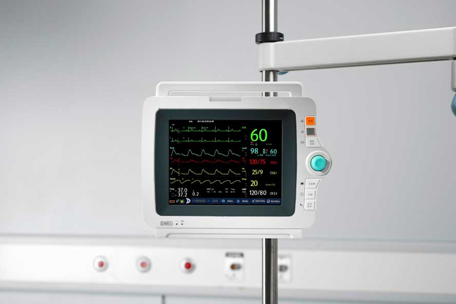
На стойке передвижения
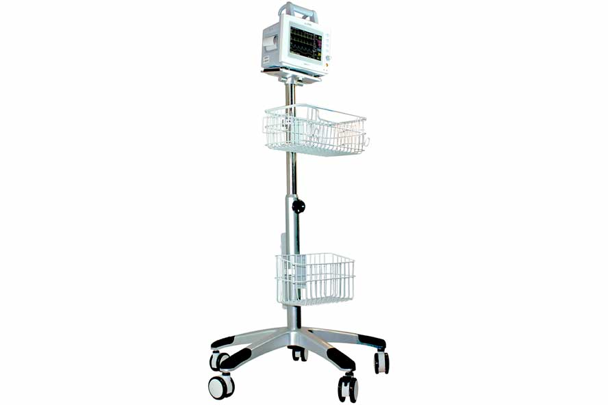
Крепление на кровать
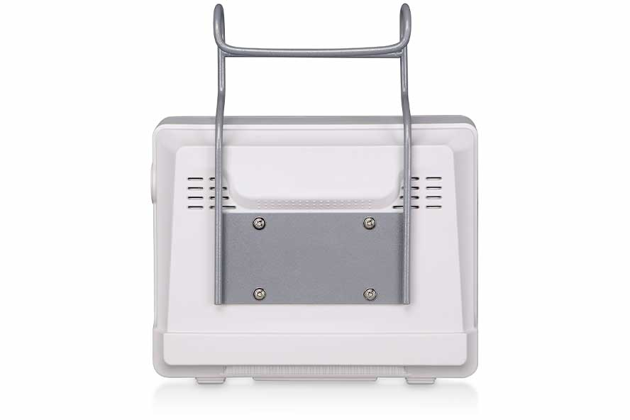
Какие параметры измеряет монитор пациента Nihon Kohden
Мониторы пациента Nihon Kohden предоставляют возможность точного и надежного измерения основных параметров здоровья. Они проводят анализ ЭКГ на 12 отведений, активно контролируя состояние ST сегментов и аритмии. Это помогает врачам быстро и точно определить состояние сердечно-сосудистой системы пациента.
С помощью импедансного метода мониторы Nihon Kohden измеряют частоту дыхания пациента. Они фиксируют количество вдохов в минуту, охватывая диапазон от 0 до 120. Это позволяет медицинскому персоналу наблюдать за состоянием дыхательной системы пациента в реальном времени.
Благодаря функции неинвазивного измерения артериального давления, мониторы Nihon Kohden могут работать в трех режимах: ручном, автоматическом и непрерывном. Они измеряют давление в диапазоне от 10 до 270 мм ртутного столба, обеспечивая точные данные о кровяном давлении пациента.
Мониторы Nihon Kohden также проводят анализ насыщенности крови кислородом, обозначаемый как SpO2. Это критически важный параметр, который показывает, насколько эффективно кровь переносит кислород по телу пациента.
Частоту пульса устройства регистрируют в диапазоне от 15 до 300 ударов в минуту. Это помогает контролировать состояние сердечной активности пациента, выявлять возможные нарушения и своевременно реагировать на них.
Для определения температуры тела пациента в мониторах используются два канала, что позволяет проводить измерения в диапазоне от 0 до 50 градусов. Такое измерение температуры обеспечивает высокую точность и позволяет отслеживать любые изменения в состоянии здоровья пациента.
Дополнительные параметры, которые отслеживает монитор пациента Nihon Kohden:
- ИАД — инвазивным методом измеряет давление от -50 до 300 мм ртутного столба
- CO2 — капнометрический модуль измеряет насыщение крови углекислым газом от 0 до 99 мм ртутного столба
- Et CO2 — измеряет концентрацию углекислого газа в конце выдоха
- СЧД — измеряет среднюю частоту дыхания за определенный период
- ФПГ — аппарат может построить фотоплетизмограмму на основе которой врач может оценить состояние сосудов
- СВ — монитор пациента оценивает общий объем крови, поступающий из сердца в сосуды за 1 минуту
- Спирометрия — анализ функции внешнего дыхания и состояния легких
Аксессуары для монитора пациента Nihon Kohden
Мониторы пациента Nihon Kohden представляет собой высокотехнологичное устройство для медицинского мониторинга, которое обеспечивает точное и надежное отслеживание состояния здоровья пациента. Он оснащен широким набором функций и комплектующих, которые обеспечивают максимальную эффективность и удобство использования.
В комплектацию мониторов входит большой цветной дисплей с высоким разрешением, который позволяет четко видеть все необходимые данные. Дисплей обладает сенсорными возможностями, что обеспечивает удобство управления и навигации. Кроме того, в комплектацию входят различные датчики и сенсоры для измерения жизненно важных показателей пациента, таких как пульс, давление, температура, уровень кислорода в крови и другие. Эти датчики легко подключаются к монитору и обеспечивают точные и надежные данные в реальном времени.
Также в комплекте с монитором идет специальное программное обеспечение, которое обеспечивает удобный интерфейс для отображения и анализа данных. Программное обеспечение позволяет настраивать параметры мониторинга в соответствии с потребностями конкретного медицинского учреждения.
Nihon Kohden оснащен встроенным аккумулятором, который обеспечивает автономную работу устройства в течение нескольких часов. Это особенно важно при перевозке пациента или при отсутствии постоянного источника питания. В общем, комплектация мониторы пациента Nihon Kohden обеспечивает все необходимое для эффективного и надежного мониторинга состояния здоровья пациента.
Примеры аксессуаров, которыми комплектуются мониторы пациента Nihon Kohden:
Пульсоксиметрический датчик
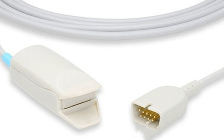
Кабель для ЭКГ (3 отведения)
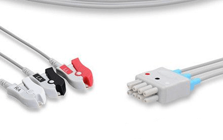
Манжета для НИАД
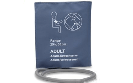
Переходник U710X-36
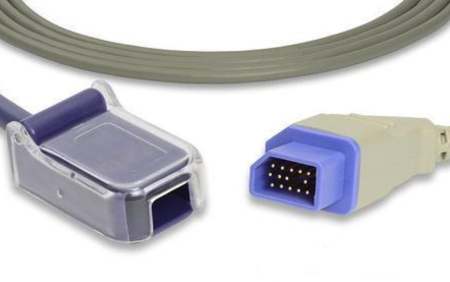
Переходник U710M-36
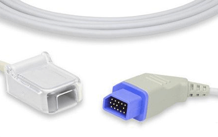
Манжета бедренная
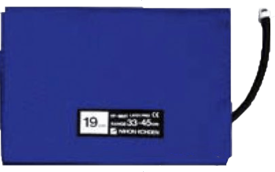
Видеообзор мониторов пациента Nihon Kohden
Цена мониторов пациента Nihon Kohden
Nihon Kohden BSM
Современный монитор пациента надежно отслеживает все показатели состояния пациента, в том числе и во время транспортировки.
Монитор пациента Nihon Kohden BSM сочетает в себе Life Scope TR и Life Scope PT, что обеспечивает непрерывный мониторинг. Вся информация о пациенте до и во время транспортировки сохраняется во внутренней памяти и передается на центральную систему мониторинга. Благодаря уникальным опциям и сенсорному управлению, а также инновационному графику тенденций Life Scope TR способствует эффективному уходу за пациентами. Nihon Kohden BSM обладает большим дисплеем.
Аппарат идеально подойдет для использования в отделениях интенсивной терапии, кардиореанимации, операционных и послеоперационных палатах.
Все мониторы производителя уже в стандартной комплектации оснащены многочисленными инновациями и дополнительными функциями.

Nihon Kohden BSM 2301K
Прикроватный монитор BSM-2301K – легкий мультипараметрический переносной монитор пациента. Диагональ сенсорного монитора 8,4 дюйма. Перед покупкой у менеджера необходимо подобрать необходимые аксессуары и модули для взрослых и детей.
Простой и понятный интерфейс помогают врачам в кратчайшие сроки освоить оборудование. Монитор пациента удобно использовать как в больничной палате, так и во время сложной хирургической операции на пациентах любых возрастов. Базовые параметры, которые можно отследить с помощью Nihon Kohden BSM 2301K – ЭКГ, пульса, частота дыхания, SpO2 , НИАД, температура
Nihon Kohden PVM 2703
Концепция монитора пациента PVM-2703 заключается в высокой простоте использования. PVM-2703 представляет собой решение для больниц, которые хотят улучшить качество и оптимизировать работу. PVM-2703 сочетает в себе высокую точность и простоту эксплуатации, чтобы удовлетворить потребности любого медицинского учреждения. Пользоваться монитором могут как эксперты, так и младший медицинский персонал. Аппарат оснащен большим 10,4 дюймовым цветным TFT ЖК-экраном с высоким разрешением, модулем ЭКГ на 3 или 6 отведений, SpO2, НИАД, импедансное дыхание, температура, ИАД или СО2. PVM 2703 позволяет хранить большой объем данных: тренды до 120 часов, аритмии, история сигналов тревоги. Так же есть возможность подключить монитор к центральной системе мониторинга
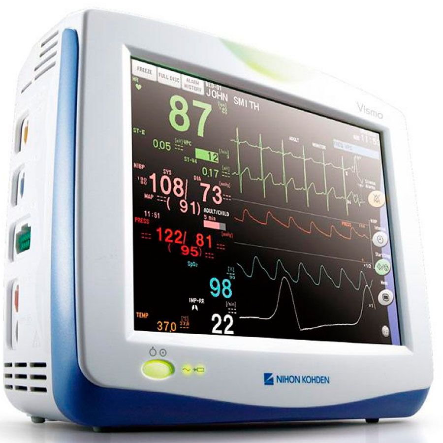
Nihon Kohden Life Scope TR
Монитор пациента Nihon Kohden Life Scope TR предлагают вам возможность стабильной работы с отдельными показателями за счет модульной конструкции. Сегодня в неотложной медицине пациенты должны находиться под наблюдением в соответствии с самыми высокими стандартами даже во время транспортировки. Многопараметрический модуль или транспортный монитор Nihon Kohden Life Scope PT и система Smart Cable обеспечивают непрерывный мониторинг и передачу данных всех тенденций, истории и настроек.
Все мониторы семейства Life Scope уже в стандартной комплектации оснащены многочисленными инновациями и дополнительными функциями.

Nihon Kohden Life Scope VS
Монитор пациента Nihon Kohden Life Scope VS предлагает широкий спектр функций для использования во многих клинических областях. Аппарат сочетает в себе классические функции и передовые технологии в компактном корпусе. Серия Lifescope VS предлагается с двумя различными базовыми моделями – экран 12,1 » и 15″. На выбор можно установить различные модули, которые обеспечивают оптимальный мониторинг пациентов для всех областей применения. К аппарату можно подключить до двух внешних мониторов и термопринтер. Монитор пациента оснащен модульной конструкцией. Теперь медицинское учреждение может сэкономить бюджет, достаточно купить только те модули, которые решают ваши клинические задачи. Life Scope VS обладает высокой гибкостью, но при этом прост в эксплуатации.
Nihon Kohden PVM
Постоянное наблюдение за пациентом имеет жизненно важное значение. Для эффективного лечения, данные пациента должны передаваться моментально и без серьезных погрешностей. Nihon Kohden PVM интеллектуальный монитор пациента с удобными экранными инструкциями по эксплуатации. Это делает мониторинг еще проще, поскольку проблемы можно не только выявлять, но и решать благодаря описаниям и иллюстрациям. PVM это практичный, простой в использовании и высокоточный монитор пациента, которые идеально подходят для любых ситуаций.
В Nihon Kohden PVM возможно сохранять данные до 120 часов трендов, аритмий, табличные и графические данные. В PVM встроен аритмии анализатор EC1, который устраняет ложные тревоги и модуль измерения НИАД.
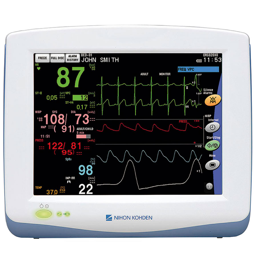
Nihon Kohden Life Scope G9
Life Scope G9 — использует все инновационные технологии для точного отслеживания параметров пациента. G9 предлагает комбинированное отображение данных пациента на основе текущих и исторических данных в удобном для пользователя интерфейсе. Life Scope G9 имеет модульную конструкцию, что позволяет докупить отдельно только нужные модули, которые решат ваши клинические задачи. Благодаря разъему MULTI и системе Smart Cable возможно быстрое и безболезненное измерение артериального давления с помощью iNIBP – специальный алгоритм измерения НИАД.
Динамический дисплей самостоятельно подбирает какие параметры важно выводить на экран. Существует три варианта исполнения монитора (широкоэкранный 24″, 22″ и 19″). На экране одновременно можно вывести до 17 кривых. В программное обеспечение установлены различные варианты макетов для каждого дисплея, между которыми можно переключаться с помощью одного клика мыши.
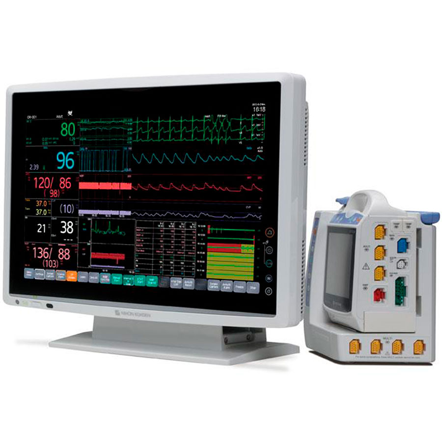
Nihon Kohden Life Scope G5
Life Scope G5 от Nihon Kohden был разработан на новой платформе с размерами монитора 12,1 дюйма или 15,6 дюйма. Существует также возможность подключить до двух дополнительных дисплеев. Благодаря расширенным функциям Life Scope G5 врачи могут использовать монитор пациента в различных отделениях больницы. У модели Life Scope G5 низкое число ложных срабатываний, а трудозатраты и время диагностики, Life Scope G5 позволяет улучшить лечение и ведение пациентов, предоставляя дополнительную информацию к стандартным процедурам.
Монитор пациента Life Scope G5 обеспечивает высокое качество отслеживания параметров пациента во время транспортировки пациентов благодаря своим интеллектуальным технологиям. Life Scope G5 предлагает следующие инновационные решения: быстрое реагирование без дополнительной работы iNIBP, Быстрое и безболезненное неинвазивное измерение артериального давления с помощью технологии iNIBP, PWTT – время прохождения пульсовой волны, которое регистрируется при измерении НИАД и используется для обнаружения колебаний артериального давления, esCCO улучшенный гемодинамический мониторинг без дополнительных датчиков, затрат или процедур позволяет клиницистам проводить неинвазивное и инвазивное ВЗК даже у менее критических пациентов.
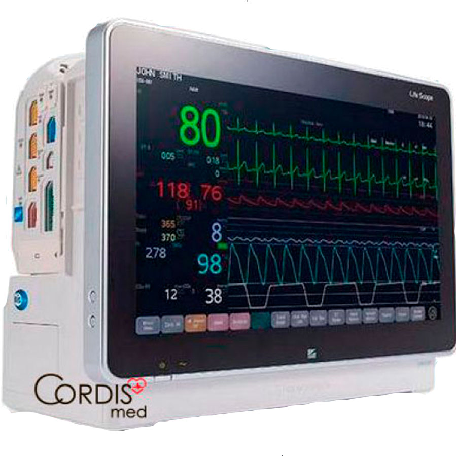
Nihon Kohden Life Scope PT
Life Scope PT был специально разработан для обеспечения сложного мониторинга за пределами палаты пациента. Он оснащен системой Smart Cable. Измерения начинаются автоматически, как только кабель подключат к мультиразъему. Гибкая функциональность Life Scope PT отображает несколько жизненно важных параметров и служит для различных вариантов применения: его можно использовать как автономное устройство на выезде или стационарно в палате пациента.
Life Scope PT обладает идеальными портативными функциями: компактный и прочный корпус гарантирует постоянный и безопасный мониторинг при транспортировке. Небольшой вес всего 1,57 кг (включая батарею). Постоянная передача данных и кривых на центральный монитор после транспортировки. Общий вид: Большой 5,7-дюймовый сенсорный экран с высоким разрешением, Таблицы и графические кривые трендов, Система Smart Cable и 3 мультиразъема для гибкого и оптимального мониторинга.
Аппарат может работать автономно в течение пяти часов от батареи. На Nihon Kohden Life Scope PT можно записать до 72 часов данных трендов
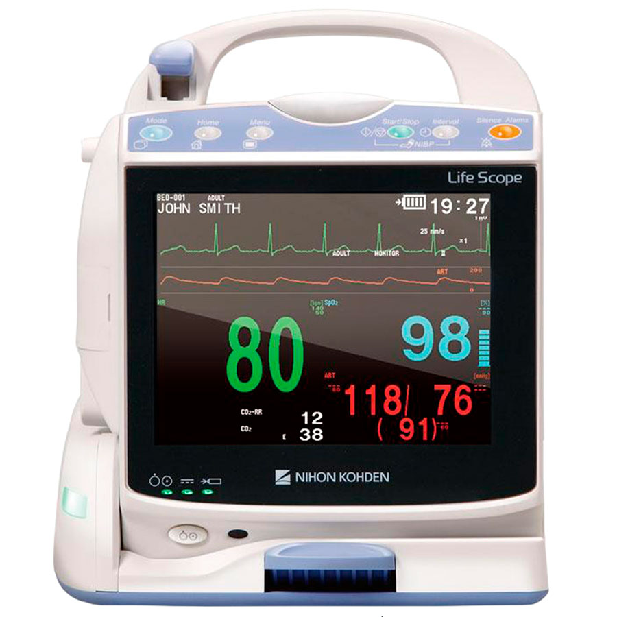
Nihon Kohden PVM 2701
Монитор пациента Nihon Kohden PVM 2701 оснащен модулем мониторинга ЭКГ, пульса, частоты дыхания, SpO2, НИАД и температуры. Большой и четкий сенсорный экран обеспечивает простое и интуитивно понятное управление. В настройках можно выбрать один из нескольких макетов представления данных. Встроенная иллюстрированная инструкция поможет персоналу быстро ориентироваться в функциях аппарата. PVM 2701 имеет 10,4-дюймовый цветной TFT ЖК-экран, сенсорный экран на котором можно отобразить до 4 кривых и 5 параметров. В памяти можно сохранить до 120 часов числовых и графических данных тренда, 120 часов полного раскрытия кривой ЭКГ, всесторонний анализ аритмии и воспроизведение сохраненных событий аритмии, PWTT (Время прохождения пульсовой волны), запуск измерения НИАД в зависимости от времени прохождения импульса. Опционально доступен 3-канальный рекордер.
Консультация по выбору монитора пациента Nihon Kohden
Наши менеджеры имеют медицинское образование и смогут провести профессиональную консультацию по любым мониторам пациента и дополнительным принадлежностям к ним. CordisMed работает напрямую с производителем и имеет максимальные оптовые скидки.
Свяжитесь с нашими менеджерами по бесплатному телефону 8 (800) 555-30-19 или оставьте заявку
Теги:
User manual containes information about installation, usage and general care of nihon kohden cns 9701 central monitor. Time synchronized review data of bedside monitor. Nihon kohden bsm 5100a operating manual. Der start in die nihon kohden welt. Der einfache monitor für alle abteilungen.

Nihon kohden bsm 5100a operating manual.
Der start in die nihon kohden welt. Systemen des partners nihon kohden als . Der einfache monitor für alle abteilungen. Nihon kohden · life scope bedside monitors. Operator’s manual, user’s guide(2vols.), administrator’s guide, & service manual for life scope tr bedside monitor: Time synchronized review data of bedside monitor. Nihon kohden bsm 5100a operating manual. User manual containes information about installation, usage and general care of nihon kohden cns 9701 central monitor. Löwenstein medical bietet den kunden die möglichkeit der planung und realisierung von patientenmonitoring.
Der einfache monitor für alle abteilungen. Nihon kohden bsm 5100a operating manual. User manual containes information about installation, usage and general care of nihon kohden cns 9701 central monitor. Nihon kohden · life scope bedside monitors. Time synchronized review data of bedside monitor.

Der einfache monitor für alle abteilungen.
User manual containes information about installation, usage and general care of nihon kohden cns 9701 central monitor. Nihon kohden bsm 5100a operating manual. Löwenstein medical bietet den kunden die möglichkeit der planung und realisierung von patientenmonitoring. Operator’s manual, user’s guide(2vols.), administrator’s guide, & service manual for life scope tr bedside monitor: Der einfache monitor für alle abteilungen. Der start in die nihon kohden welt. Nihon kohden · life scope bedside monitors. Time synchronized review data of bedside monitor. Systemen des partners nihon kohden als .
User manual containes information about installation, usage and general care of nihon kohden cns 9701 central monitor. Nihon kohden · life scope bedside monitors. Systemen des partners nihon kohden als . Operator’s manual, user’s guide(2vols.), administrator’s guide, & service manual for life scope tr bedside monitor: Time synchronized review data of bedside monitor.

Time synchronized review data of bedside monitor.
Löwenstein medical bietet den kunden die möglichkeit der planung und realisierung von patientenmonitoring. Systemen des partners nihon kohden als . User manual containes information about installation, usage and general care of nihon kohden cns 9701 central monitor. Der start in die nihon kohden welt. Nihon kohden · life scope bedside monitors. Time synchronized review data of bedside monitor. Nihon kohden bsm 5100a operating manual. Der einfache monitor für alle abteilungen. Operator’s manual, user’s guide(2vols.), administrator’s guide, & service manual for life scope tr bedside monitor:
Nihon Kohden Monitor — User Manual : Nihon Kohden Bsm 2301k Manuals Manualslib /. Operator’s manual, user’s guide(2vols.), administrator’s guide, & service manual for life scope tr bedside monitor: Nihon kohden · life scope bedside monitors. Time synchronized review data of bedside monitor. Löwenstein medical bietet den kunden die möglichkeit der planung und realisierung von patientenmonitoring. Der einfache monitor für alle abteilungen.
Назначение
Мониторы прикроватные “BSM-23**“,модификации: BSM-2301K, BSM-2303K, BSM-235IK, BSM-2353K (далее — мониторы) предназначены для измерений и регистрации биоэлектрических потенциалов сердца, температуры тела непрерывного неинвазивного определения насыщения (сатурации) кислородом гемоглобина артериальной крови (SpOi) и частоты пульса (ЧП) и частоты дыхания, определения систолического и диастолического артериального давления (АД), измерение содержания двуокиси углерода и наблюдения на экране монитора электрокардиограммы (ЭКГ), сигнала дыхания, значений или графиков’ измеряемых параметров состояния пациента и включения тревожной сигнализации при выходе измеряемых параметров за установленные пределы.
Область применения — отделения реанимации и палаты интенсивной терапии, амбулаторные отделения, на постах медицинской сестры клиник, больниц, госпиталей и других лечебно-профилактических учреждений, в машинах скорой помощи.
ОПИСАНИЕ ,
Функционально мониторы прикроватные построены по модульному типу и конструктивно состоят из системного блока, модуля регистрации и интерфейса, обеспечивающего передачу информации на центральный монитор.
Принцип работы канала артериального давления основан на определение систолического и диастолического артериального давления косвенным осциллометрическим способом;
Принцип работы канала дыхания основан на измерении импеданса между двумя электродами, установленными на грудь пациента.
Принцип работы канала температуры основан на измерение и регистрации температуры тела пациента терморезисторами.
Принцип работы канала электрокардиографии основан на прямом измерении электрического потенциала сердца с помощью электродов, закрепленных на теле пациента.
Принцип работы канала пульсоксиметрии основан на различии спектрального поглощения оксигемоглобина и восстановленного гемоглобина крови на двух длинах волн.
Принцип работы канала капнометрии основан на измерении и регистрации массовой концентрации двуокиси углерода (EtCCh) в выдыхаемом пациентом воздухе от неинвазивного капнографа. Уровень СО2 отображается либо в %, либо в мм рт. ст. Уровни других газов измеряются в %.
Экран монитора разделён на несколько областей отображения информации: область графической информации; область информации о пациенте; область числовых значений измеряемых параметров и область системной информации. Монитор имеет несколько видов отображения информации: в виде кривых для параметров ЭКГ, дыхания, пульсоксиметрии, и содержания СО2; в виде числовых данных: ЧСС, частота дыхания, частота пульса, температура, уровень СОг, параметры артериального давления. На экране монитора во всех режимах отображаются текущая дата и время. Монитор позволяет в режиме остановки проводить визуальный просмотр элементов ЭКГ.
Модификации мониторов различаются количеством мультипараметрических входов (один или два), размером экрана (8,4 или 10,2 дюйма), потребляемой мощьностью.
Технические характеристики
1. Электрокардиографический канал.
1 1.1. Диапазон измерений входных напряжений: от 0,5 до 5 мВ.
1.2. Пределы допускаемой относительной погрешности монитора при измерении йа-пряжений: ± 5 %.
1.3. Входной импеданс, не менее: 5 МОм.
1.4. Коэффициент ослабления синфазной помехи, не менее: 90 дБ.
1.5. Напряжение внутренних шумов, приведенных ко входу, не более: 30 мкВ.
1.6. Пределы допускаемой абсолютной погрешности монитора при измерении частоты сердечных сокращений в диапазоне от 0,12 до 300 мин’1, мин’1: ±2.
2. Канал пульсоксиметрии.
2.1. Пределы допускаемой абсолютной погрешности монитора в диапазоне от 50 до 80 % при измерении БрОг, %: ±3;
2.2. Пределы допускаемой абсолютной погрешности монитора в диапазоне от 80 до 100 % при измерении БрОг, %: ±2.
2.3. Диапазон измерения частоты пульса, мин’1: от 20 до 250;
2.4. Пределы допускаемой абсолютной погрешности измерений частоты пульса: ± 3 мин’1;
3. Канал частоты дыхания (импедансный метод).:
3.1. Диапазон измерений базового импеданса от 0,01 до 2 кОм;
3.2. Диапазон измерений переменной составляющей импеданса от 0,05 до 10 Ом;
3.3. Диапазон измерения частоты дыхания (ЧД) от 0 до 150 мин-1 при переменной составляющей импеданса не менее 200 МОм;
3.4. Пределы допускаемой абсолютной погрешности монитора при измерении частоты дыхания, мин-1: ±2.
4. Канал артериального давления.
4.1. Диапазон измерений избыточного давления в компрессионной манжете, кПа (мм рт.ст.): от 0 до 40 (от 0 до 300);
4.2. Пределы допускаемой погрешности монитора при измерении избыточного давления в компрессионной манжете:
— абсолютная в диапазоне от 0 до 26 (от 0 до 200) кПа (мм рт.ст.), кПа (мм рт.ст.): ±0,39 (±3);
— абсолютная в диапазоне от 26 до 40 (от 200 до 300) кПа (мм рт.ст.):, ±0,52 (±4).
5. Канал термометрии.
5.1. Диапазон измерений температуры, °C: от 0 до 45;
5.2. Пределы допускаемой абсолютной погрешности монитора при измерении температуры в диапазоне от 0,0 до 25,0 °C: ±0,2;
5.2. Пределы допускаемой абсолютной погрешности монитора при измерении температуры в диапазоне от 25,0 до 45,0 °C: ±0,1;
6. Канал капнометрии.
6.1. Пределы допускаемой абсолютной погрешности измерений парциального давления СО2 в выдыхаемом воздухе в диапазоне от 0 до 5,0 кПа (от 0 до 40 мм рт.ст.): ± 0,3 кПа (± 4 мм рт.ст.);
6.2. Пределы допускаемой относительной погрешности измерений парциального давления СО2 в выдыхаемом воздухе в диапазоне св. 5,2 до 9,2 кПа(св. 40 до 70 мм рт.ст.): ± 10 %.
7. Питание монитора осуществляется:
— от сети переменного тока частотой (220 ±22) В, (50 ±1) Гц;
— от аккумулятора (10HR-4/3FAUC-NK): от 10,8 до 15,0 В
8. Массо-габаритные характеристики и потребляемая мощность от сети переменного тока приведены в таблице:
|
Модификация |
Масса (без принадлежностей), кг |
Габаритные размеры, мм |
Потребляемая мощность, ВА |
|
BSM-2301K |
4,7 |
253242145 |
70 |
|
BSM-2303K |
4,7 |
253’242145 |
86 |
|
BSM-2351K |
4,7 |
253242145 |
95 |
|
BSM-2353K |
4,7 |
253242145 |
95 |
9. Условия эксплуатации:
— диапазон температуры окружающего воздуха: от 10 до 40 °C;
— диапазон относительной влажности воздуха: от 30 до 90 % (без конденсации);
— диапазон атмосферного давления: от 700 до 1060 гПа.
10. Средний срок службы: 5 лет.
Знак утверждения типа
Знак утверждения типа наносится на корпус монитора методом сеткографии и на титульный лист эксплуатационной документации.
Комплектность
НАИМЕНОВАНИЕ
I. Системный блок___________________________
2. Набор пульсоксиметрических датчиков_______
3. Набор электродов для ЭКГ_________;________
4. Набор дыхательных датчиков_______________
5. Система для измерения капнографии Р903
6. Набор датчиков температуры_______________
7. Комплект датчиков СОг___________________
8. Трансмиттер ZB-900PG____________________
9. Адаптер к трансмиттеру____________________
10. Радиостанция QI-210P_____________________
11. Сетевая карта______________________________
12. Модуль газовый AG-400RK
13. Линия забора газа V901____________________
14. Набор манжет
15. Набор соединительных кабелей и шлангов
16. Руководство оператора
17. Методика поверки. МП 242-1031- 2010
Поверка
Поверка пульсоксиметрического канала и канала капнометрии проводится в соответствии с документом МП 242-1031- 2010 «Мониторы прикроватные “BSM-23**”». Методика поверки», утвержденным ГЦИ СИ ФГУП «ВНИИМ им. Д. И. Менделеева» в июле 2010г.
Поверка электрокардиографического канала, канала артериального давления, канала измерения температуры тела пациента производится в соответствии с Р 50.2.049-2005 «ГСИ. Мониторы медицинские. Методика поверки».
Основные средства поверки:
|
Наименование |
Характеристики оборудования |
|
|
1.Генератор функциональный, ГФ-05 ГрСИ №11789-03 |
Диапазон размаха напряжения выходного сигнала: от 0,03 мВ до 20 В; диапазон частот: от 0,01 до 600 Гц |
|
|
2. Установка для поверки каналов измерений давления (УПКД), ГрСИ №23532-02 |
Диапазон измерений: 2,66 — 49,3 кПа (от 20 до 370 мм рт.ст.), Основная погрешнос: измерений: ± 0,8 мм рт.ст |
ъ |
|
3. Установка для поверки пульсоксиметров QA-510, ГрСИ №25659-03 |
коэффициент сатурации от 35 до 100 % с погрешностью ±1 %; частоты пульса от 30 до 25 мин’1; с погрешностью ± 0,5 %. |
0 |
|
4. Поверочное коммутационное устройство ПКУ-ЭКГ |
Параметры эквивалента «кожа-электрод»: Rl=51 ± 2,55 кОм, С1= 0,047; ± 0,0047 мкФ, Rn=100 ± 5 Ом, R3=2,2 МОм |
|
|
5. Установка для поверки каналов измерений частоты пульса ИАД (УПКЧП), ГрСИ №21923-01 |
Диапазон задания частоты следования импуль сов: 30 — 200 мин 4 Основная относительная погрешность задали* частоты импульсов: ±1,5% |
|
6. Термометр ртутный эталонный, ТР-1, ГрСИ №2850-02 |
Цена деления 0,01 °C; Погрешность: ± 0,03 °C |
|
|
7. Преобразователь «напряжения-сопративления» ПНС-ГФ, ТУ 9440-671-05834388-95, ГрСИ №23213-02 |
Диапазон установки постоянной составляюще сопротивления: 10-1000 Ом. Погрешность ± 2 % Диапазон установки переменной составляюще сопротивления: 0,005 -10 Ом. Погрешность ± % для значений 0,1; 0,25; 0,5; 1,0 и 10 Ом; ± 5 для значений 0,005; 0,05 Ом. |
й !Й 2 % |
|
8. Поверочное коммутационное устройство ПКУ-ЭЭГ |
1:10000 ПГ± 0,5 % 22 кОм ПГ ± 1 %, 100 Ом ПГ ± 5 % 3,3 нФ ПГ ± 5 % |
|
|
9. ПЗУ «ЭЭГ-7» с испытательным сигналом ЭЭГ-7 |
Амплитудные параметры ПГ ± 3 % Временные параметры ПГ ± 1 % |
Межповерочный интервал -1 год.
Нормативные документы
1. ГОСТ Р50267.27-94 «Изделия медицинские электрические. Часть 2. Частные требования безопасности к электрокардиографическим мониторам». !
2. ГОСТ Р 50267.30-99 «Изделия медицинские электрические. Часть 2. Частные требования безопасности к приборам для автоматического контроля давления крови косвенным методом».
3. ГОСТ Р ИСО 9919-2007 «Изделия медицинские электрические. Частные требования безопасности и основные характеристики пульсовых оксиметров».
4. ГОСТ Р 50444-92 “Приборы, аппараты и оборудование медицинские. Общие технические условия”;
5. ГОСТ Р 50267.0-92 “Изделия медицинские электрические. Часть I. Общие требования безопасности”;
6. ГОСТ Р 50267.0.4-99 “Изделия медицинские электрические. Часть I. Общие требования безопасности 4. Требования безопасности к программируемым медицинским электронным системам”
7. ГОСТ Р 50267.0.2-2005 “Изделия медицинские электрические. Часть I. Общие требования безопасности 2. Электромагнитная совместимость. Требования и методы испытд-w 5, I
НИИ
8. ГОСТ Р 50267.26-95 Изделия медицинские электрические. Часть 2. Частные требЬ-вания безопасности к элекгроэнцефалографам”
9. ГОСТ Р МЭК 60601-1-1-2007 “Изделия медицинские электрические. Часть I. Общие требования безопасности к медицинским электрическим системам”
10. Техническая документация фирмы «NIHON KOHDEN CORPORATION», Япония,
Заключение
Тип мониторов “BSM-23**“, модификации: BSM-2301K, BSM-2303K, BSM-235IK, BSM-2353K утвержден с техническими и метрологическими характеристиками, приведенными в настоящем описании типа, и метрологически обеспечен при ввозе в РФ, в процессе эксплуатации и после ремонта.
Мониторы разрешены Федеральной службой по надзору в сфере здравоохранения и социального развития на применение в медицинской практике и имеют сертификаты соответствия ГОСТ Р:
|
Модификация мониторы |
Сертификат соответствия ГОСТР |
Регистрационное удостоверение |
|
|
BSM-2301K |
РОСС JP. НО03.В03339 от 13.04.2009, ОС ООО «ТЕХНОНЕФТЕГАЗ» |
М3 РФ №2002/110 о’ 11.03.2002 |
г |
|
BSM-2303K |
РОСС ЛР.АЯ46.В14633 от 27.02.2008, выдан ОС промышленной продукции РОСТЕСТ-МОСКВА |
ФС 2004/847 от 03.08.2004 |
|
|
BSM-2351K |
РОСС 1Р.АЯ46.В14633 от 27.02.2008, выдан ОС промышленной продукции РОСТЕСТ-МОСКВА |
ФС 2005/1092 от 04.08.2005 |
|
|
BSM-2353K |
РОСС JP.AH46.B 14633 от 27.02.2008, выдан ОС промышленной продукции РОСТЕСТ-МОСКВА |
ФС 2005/1092 от * 04.08.2005 |