
![]()
Operating Instructions
Laboratory Glassware Washer for
Laboratory Glassware and Utensils
PG 8583 CD
|
To prevent accidents and machine dam- |
en — US |
|
age, read these instructions before in- |
|
|
stallation or use. |
M.-Nr. 10 607 862

2

|
Contents |
|
|
Guide to the manual ………………………………………………………………………………………….. |
8 |
|
Definition of terms ………………………………………………………………………………………………. |
8 |
|
IMPORTANT SAFETY INSTRUCTIONS ……………………………………………………………….. |
9 |
|
Symbols on the machine……………………………………………………………………………………… |
14 |
|
Proper use………………………………………………………………………………………………………… |
15 |
|
User profiles……………………………………………………………………………………………………… |
16 |
|
User profiles ………………………………………………………………………………………………………. |
16 |
|
Product description…………………………………………………………………………………………… |
17 |
|
Machine overview……………………………………………………………………………………………….. |
17 |
|
Control panel……………………………………………………………………………………………………… |
18 |
|
LEDs in the buttons…………………………………………………………………………………………….. |
19 |
|
Operation………………………………………………………………………………………………………….. |
20 |
|
Display illustrations……………………………………………………………………………………………… |
20 |
|
Switching on………………………………………………………………………………………………………. |
21 |
|
Switching off………………………………………………………………………………………………………. |
21 |
|
Auto-off function ………………………………………………………………………………………………… |
21 |
|
Ready for operation (standby) ………………………………………………………………………………. |
21 |
|
Display interface…………………………………………………………………………………………………. |
22 |
|
Menu operation ………………………………………………………………………………………………….. |
22 |
|
Settings in the menu …………………………………………………………………………………………… |
23 |
|
Symbols in the display ………………………………………………………………………………………… |
24 |
|
Commissioning…………………………………………………………………………………………………. |
25 |
|
Installation and connection ………………………………………………………………………………….. |
25 |
|
Procedure ………………………………………………………………………………………………………….. |
25 |
|
Opening and closing the door……………………………………………………………………………. |
29 |
|
Electronic door lock ……………………………………………………………………………………………. |
29 |
|
Opening the door ……………………………………………………………………………………………….. |
29 |
|
Closing the door…………………………………………………………………………………………………. |
29 |
|
Opening the door using the emergency release ……………………………………………………… |
30 |
|
Water softener ………………………………………………………………………………………………….. |
31 |
|
Water hardness ………………………………………………………………………………………………….. |
31 |
|
Setting the water hardness level …………………………………………………………………………… |
32 |
|
Filling the salt container ………………………………………………………………………………………. |
34 |
|
Salt refill reminder……………………………………………………………………………………………….. |
36 |
|
Application technology ……………………………………………………………………………………… |
37 |
|
Mobile units, baskets, modules and inserts……………………………………………………………. |
37 |
|
Adjusting the height of the upper basket ……………………………………………………………….. |
38 |
|
Preparing the load ………………………………………………………………………………………………. |
40 |
|
Chemical processes and technology …………………………………………………………………. |
44 |
|
Adding and dispensing process chemicals ………………………………………………………… |
48 |
|
Dispensing systems ……………………………………………………………………………………………. |
48 |
|
Labeling of the suction wands ………………………………………………………………………….. |
48 |
3

|
Contents |
|
|
Neutralizing agent……………………………………………………………………………………………….. |
49 |
|
Replenishing neutralizing agent ………………………………………………………………………… |
49 |
|
Refill indicator…………………………………………………………………………………………………. |
50 |
|
Dispensing neutralizing agent …………………………………………………………………………… |
50 |
|
Process chemicals ……………………………………………………………………………………………… |
51 |
|
Refilling liquid process chemicals ……………………………………………………………………… |
52 |
|
Refill indicator…………………………………………………………………………………………………. |
53 |
|
Dispensing liquid process chemicals …………………………………………………………………. |
53 |
|
Operation………………………………………………………………………………………………………….. |
54 |
|
Selecting a program ……………………………………………………………………………………………. |
54 |
|
Starting a program ……………………………………………………………………………………………… |
54 |
|
Starting a program using delay start ………………………………………………………………….. |
54 |
|
Drying ……………………………………………………………………………………………………………. |
56 |
|
Program cycle display …………………………………………………………………………………………. |
58 |
|
Program end………………………………………………………………………………………………………. |
58 |
|
Interrupting a program…………………………………………………………………………………………. |
59 |
|
Canceling a program …………………………………………………………………………………………… |
60 |
|
Program canceled due to a fault ……………………………………………………………………….. |
60 |
|
Canceling a program manually………………………………………………………………………….. |
60 |
|
System messages ………………………………………………………………………………………………. |
61 |
|
Changing the filter …………………………………………………………………………………………… |
61 |
|
Cleaning the filter combination………………………………………………………………………….. |
61 |
|
Low fill levels ………………………………………………………………………………………………….. |
61 |
|
Spray arm pressure and monitoring ………………………………………………………………………. |
62 |
|
Settings …………………………………………………………………………………………………………. |
63 |
|
Delay Start…………………………………………………………………………………………………………. |
64 |
|
Drying ……………………………………………………………………………………………………………….. |
65 |
|
DOS priming………………………………………………………………………………………………………. |
67 |
|
Language ……………………………………………………………………………………………………….. |
68 |
|
Time of day………………………………………………………………………………………………………… |
69 |
|
Volume………………………………………………………………………………………………………………. |
72 |
|
Additional settings …………………………………………………………………………………………… |
73 |
|
Code…………………………………………………………………………………………………………………. |
75 |
|
Entering a PIN code ………………………………………………………………………………………… |
75 |
|
Date ………………………………………………………………………………………………………………….. |
78 |
|
Log book …………………………………………………………………………………………………………… |
80 |
|
Report……………………………………………………………………………………………………………….. |
81 |
|
Temperature unit…………………………………………………………………………………………………. |
81 |
|
Program settings ………………………………………………………………………………………………… |
81 |
|
Air cooling …………………………………………………………………………………………………………. |
82 |
|
Program release …………………………………………………………………………………………………. |
83 |
|
Moving a program: allocating program selection buttons…………………………………………. |
84 |
|
Dispensing systems ……………………………………………………………………………………………. |
85 |
|
DOS priming…………………………………………………………………………………………………… |
86 |
|
Test program ……………………………………………………………………………………………………… |
88 |
|
Filter maintenance ………………………………………………………………………………………………. |
89 |
|
Cleaning the filters in the wash cabinet ……………………………………………………………… |
89 |
|
Activating and setting the interval ……………………………………………………………………… |
89 |
|
Interface ……………………………………………………………………………………………………………. |
91 |
4

|
Contents |
|
|
Water hardness ………………………………………………………………………………………………….. |
94 |
|
Display: Temperature…………………………………………………………………………………………… |
94 |
|
Display: Brightness and contrast ………………………………………………………………………….. |
95 |
|
Switch off after …………………………………………………………………………………………………… |
96 |
|
Ready for operation (standby) …………………………………………………………………………… |
96 |
|
Auto-Off function…………………………………………………………………………………………….. |
96 |
|
Switching off after activating…………………………………………………………………………….. |
97 |
|
Factory default……………………………………………………………………………………………………. |
98 |
|
Software version…………………………………………………………………………………………………. |
98 |
|
Program settings ………………………………………………………………………………………………. |
99 |
|
Adjusting program settings ………………………………………………………………………………….. |
99 |
|
Program structure……………………………………………………………………………………………….. |
99 |
|
Program header………………………………………………………………………………………………. |
99 |
|
Program blocks ………………………………………………………………………………………………. |
100 |
|
Opening the menu………………………………………………………………………………………………. |
101 |
|
Resetting a program……………………………………………………………………………………………. |
101 |
|
Altering a program ……………………………………………………………………………………………… |
102 |
|
Allocating wash blocks…………………………………………………………………………………….. |
102 |
|
Spray-arm monitoring ……………………………………………………………………………………… |
103 |
|
Measuring conductivity ……………………………………………………………………………………. |
105 |
|
Changing water quantity ………………………………………………………………………………….. |
108 |
|
Increasing drainage time ………………………………………………………………………………….. |
109 |
|
Setting the concentration …………………………………………………………………………………. |
110 |
|
Setting the wash block temperature ………………………………………………………………….. |
111 |
|
Drying unit ……………………………………………………………………………………………………… |
113 |
|
Process documentation…………………………………………………………………………………….. |
117 |
|
Outputting batch protocols retrospectively…………………………………………………………….. |
120 |
|
External software…………………………………………………………………………………………….. |
120 |
|
Protocol printer……………………………………………………………………………………………….. |
120 |
|
Maintenance measures……………………………………………………………………………………… |
121 |
|
Maintenance………………………………………………………………………………………………………. |
121 |
|
Routine checks…………………………………………………………………………………………………… |
122 |
|
Cleaning the filters in the wash cabinet …………………………………………………………………. |
122 |
|
Checking and cleaning the spray arms ………………………………………………………………….. |
124 |
|
Cleaning the machine………………………………………………………………………………………….. |
126 |
|
Cleaning the control panel ……………………………………………………………………………….. |
126 |
|
Cleaning the door and the door seal………………………………………………………………….. |
126 |
|
Cleaning the wash cabinet ……………………………………………………………………………….. |
126 |
|
Cleaning the door front ……………………………………………………………………………………. |
126 |
|
Preventing resoiling …………………………………………………………………………………………. |
126 |
|
Checking mobile units, baskets, modules and inserts……………………………………………… |
127 |
|
Filter change………………………………………………………………………………………………………. |
128 |
|
Changing the coarse filter ………………………………………………………………………………… |
128 |
|
Replacing the HEPA filter …………………………………………………………………………………. |
129 |
|
Resetting the operating hours counter……………………………………………………………….. |
130 |
|
Performance check …………………………………………………………………………………………….. |
132 |
|
Frequently asked questions ………………………………………………………………………………. |
135 |
|
Technical faults and messages …………………………………………………………………………….. |
135 |
|
Dispensing/dispensing systems……………………………………………………………………………. |
136 |
5

|
Contents |
|
|
Insufficient salt/water softener ……………………………………………………………………………… |
137 |
|
Cancel with fault code…………………………………………………………………………………………. |
138 |
|
Process-related faults and messages ……………………………………………………………………. |
142 |
|
Door………………………………………………………………………………………………………………….. |
144 |
|
Unsatisfactory cleaning and corrosion…………………………………………………………………… |
144 |
|
Spray arm monitoring/conductivity/wash pressure………………………………………………….. |
146 |
|
Water inlet and drainage ……………………………………………………………………………………… |
148 |
|
Noises……………………………………………………………………………………………………………….. |
149 |
|
Printer/serial interface …………………………………………………………………………………………. |
149 |
|
Frequently asked questions ………………………………………………………………………………. |
150 |
|
Cleaning the drain pump and non-return valve……………………………………………………….. |
150 |
|
Cleaning the filters in the water inlet ……………………………………………………………………… |
151 |
|
Retrofitting the large-surface filter……………………………………………………………………… |
151 |
|
After sales service…………………………………………………………………………………………….. |
152 |
|
Contacting Customer Service ………………………………………………………………………………. |
152 |
|
Software version…………………………………………………………………………………………………. |
153 |
|
Installation………………………………………………………………………………………………………… |
154 |
|
Installation and alignment ……………………………………………………………………………………. |
154 |
|
Fitting the lid………………………………………………………………………………………………………. |
155 |
|
Built-under a continuous countertop …………………………………………………………………….. |
156 |
|
Preventing heat accumulation…………………………………………………………………………… |
156 |
|
Electromagnetic compatibility (EMC) …………………………………………………………………….. |
157 |
|
Electrical connection ………………………………………………………………………………………… |
158 |
|
Additional equipotential bonding ………………………………………………………………………….. |
158 |
|
Peak-load negotiation …………………………………………………………………………………………. |
159 |
|
Plumbing ………………………………………………………………………………………………………….. |
160 |
|
Connecting the water supply ……………………………………………………………………………….. |
160 |
|
Retrofitting the large-surface filter……………………………………………………………………… |
161 |
|
Connecting the water drain ………………………………………………………………………………….. |
162 |
|
Program chart…………………………………………………………………………………………………… |
163 |
|
General program information ……………………………………………………………………………….. |
163 |
|
Programs for specific soiling ………………………………………………………………………………… |
164 |
|
Programs for specific wash items …………………………………………………………………………. |
164 |
|
Additional programs ……………………………………………………………………………………………. |
165 |
|
Program selection depending on the accessories used …………………………………………… |
165 |
|
Program parameters …………………………………………………………………………………………. |
166 |
|
Free memory ……………………………………………………………………………………………………… |
166 |
|
Free memory ……………………………………………………………………………………………………… |
167 |
|
Mini…………………………………………………………………………………………………………………… |
168 |
|
Standard……………………………………………………………………………………………………………. |
169 |
|
Normal plus ……………………………………………………………………………………………………….. |
170 |
|
Intensive ……………………………………………………………………………………………………………. |
171 |
|
Injector Plus……………………………………………………………………………………………………….. |
172 |
|
Inorganic……………………………………………………………………………………………………………. |
173 |
|
Organic……………………………………………………………………………………………………………… |
174 |
|
Oil program………………………………………………………………………………………………………… |
175 |
|
Plastics ……………………………………………………………………………………………………………… |
176 |
6

|
Contents |
|
|
Pipettes …………………………………………………………………………………………………………….. |
177 |
|
Special 93°C-10′ ………………………………………………………………………………………………… |
178 |
|
Technical details……………………………………………………………………………………………….. |
179 |
|
Caring for the environment ……………………………………………………………………………….. |
180 |
|
Disposal of packaging material ……………………………………………………………………………. |
180 |
7

Guide to the manual
Warnings
Information which is important for safety is highlighted in a thick framed box with a warning symbol. This alerts you of potential danger of injury to people or damage to property.
Read these warning notes carefully and observe the instructions and codes of practice described.
Notes
Notes contain information that is particularly important to follow.
They are highlighted by a thickly framed box.
Additional information and comments
Additional information and comments are contained in a simple frame.
Operating steps
Operating steps are indicated by a black square bullet point.
Example:
Select an option using the arrow buttons and save your choice with
OK.
Display
Certain functions are shown in display messages using the same font as used for the function itself in the display.
Example:
Menu Settings .
Definition of terms |
|
Machine |
In these operating instructions, the Laboratory Glassware Washer is |
|
referred to as “the machine”. |
|
Wash items |
The term “wash items” is used wherever the items to be reprocessed |
|
are not defined in any further detail. |
|
Wash water |
The term “wash water” is used for the mixture of water and process |
|
chemicals. |
8

IMPORTANT SAFETY INSTRUCTIONS
This machine complies with all statutory safety requirements. However, inappropriate use can lead to personal injury and material damage.
Read these instructions carefully before using the machine for the first time to avoid the risk of accidents and damage to the machine. Keep these instructions in a safe place where they are accessible to users at all times.
Proper use
Use of the machine is only approved for the applications stated in the operating instructions. Conversions, modifications, and any other use are not permitted and could be dangerous.
The cleaning and disinfection processes are only designed for laboratory glassware and utensils which are designated as reprocessable by the manufacturer. The information provided by the manufacturer of the wash items must be observed.
This machine is intended for indoor use in a stationary location only.
Risk of injury
Please pay attention to the following notes to avoid injury.
The machine should only be installed, commissioned, repaired, and maintained by a Miele authorized technician. A Miele service contract is recommended to ensure full compliance with the normative and regulatory provisions. Incorrect repairs can cause considerable danger to users.
Do not install the machine in an area where there is any risk of explosion or of freezing conditions.
In order to reduce the risk of water damage, the area around the machine should be limited to furniture and fittings that are designed for use in commercial environments.
Some metal parts pose a risk of injury/being cut. Wear cut-resis- tant protective gloves when transporting and setting up the machine.
If the machine is built under a countertop, it must only be installed under a continuous countertop run which is firmly secured to adjacent units to improve stability.
The electrical safety of this machine can only be guaranteed if it is grounded properly. It is essential that this standard safety requirement is met. If in any doubt, please have the on-site wiring system tested by a qualified electrician. Miele cannot be held liable for the consequences of an inadequate grounding system (e.g. electric shock).
A damaged or leaking machine could be dangerous and compromise your safety. Disconnect the machine from the electrical supply immediately and contact Miele Service.
9

IMPORTANT SAFETY INSTRUCTIONS
Label machines which have been taken out of operation and lock them to prevent them being switched on again without authorization. The machine may only be put back into operation once it has been successfully repaired by Miele a Miele authorized technician.
As standard, the drain water of the machine will reach temperatures greater than 160 °F (70 °C). At this temperature, drain water can potentially damage the drain system. In order to reduce damage to the drain system, Miele offers an optional drain water cool-down kit.
Personnel operating the machine should be trained regularly. Untrained personnel must not be allowed access to the machine or its controls.
Only use process chemicals which have been approved by their manufacturer for the relevant application. The manufacturer of the process chemicals is liable for any negative influences on the material of the wash items and the machine.
Use caution when handling process chemicals. These may contain irritant, corrosive or toxic ingredients.
Please observe the process chemical manufacturer’s safety instructions and safety data sheets.
Wear protective gloves and goggles.
The machine is designed for operation with water and recommended additive process chemicals only. Organic solvents and flammable liquid agents must not be used as this could cause an explosion, damage rubber or plastic components in the machine and cause liquids to leak out of it.
The water in the wash cabinet is NOT safe to drink!
Do not lift the machine by protruding parts such as the control panel or the opened service flap as these could be damaged or torn off.
Do not sit or lean on the opened door. This could cause the machine to tip and get damaged or cause injury.
Be careful when sorting wash items with sharp, pointed ends. Position them in the machine so that you will not hurt yourself or create a danger for others.
Broken glass can result in serious injury during loading or unloading. Broken glass items must not be processed in the machine.
When operating the machine, beware of the high temperatures involved. If you bypass the electrical lock to open the door, there is a risk of scalding or chemical burns.
Should personnel accidentally come into contact with toxic vapors or process chemicals, follow the emergency instructions given in the manufacturer’s safety data sheets.
10
![]()
IMPORTANT SAFETY INSTRUCTIONS
Mobile units, baskets, modules, inserts and the load must be allowed to cool down before they are unloaded. Any water remaining in containers could still be very hot. Empty them into the wash cabinet before taking them out.
Never clean the machine with a water hose or a pressure washer.
The machine must be disconnected from the electrical supply before any maintenance or repair work is carried out.
Quality assurance
The following points should be observed to assist in maintaining quality standards when processing laboratory glassware and utensils and avoid damage to the loads being cleaned.
If it is necessary to interrupt a program, as an exception only, this may only be done by authorized personnel.
The cleaning standard must be routinely confirmed by the user. The process should be validated on a regular basis, and checked against documented control results.
For thermal disinfection, use temperatures and temperature holding times to achieve the required infection prophylaxis in accordance with current health and safety regulations.
Make sure items being washed are suitable for machine reprocessing and are in good condition. Plastic items must be thermally stable. Nickel plated items and aluminum items can be machine processed using special procedures only.
Items containing iron, and soiling containing residual rust must not be placed in the cabinet.
Process chemicals can, in certain circumstances, cause damage to the machine. Always follow the recommendations of the process chemical manufacturer.
In case of damage or doubt about compatibility, please contact Miele.
Cleaning detergents containing chlorine can damage the elastomers of the machine.
If the use of process chemicals containing chlorine is required, a maximum temperature of 167°F (75°C) in the “Cleaning” program phases is recommended (see program chart).
In machines equipped with special oil-resistant elastomers (from the factory) for oil and grease applications, cleaning detergents containing chlorine may not be used!
Abrasive substances must not be placed in the machine as they could cause damage to the mechanical components of the water supply. Any residues of abrasive substances on items to be washed must be removed without trace before reprocessing in the machine.
11

IMPORTANT SAFETY INSTRUCTIONS
Pre-treatments with cleaning agents can create foam, as can certain types of soiling and process chemicals. Foam can have an adverse effect on the cleaning result.
Processes must be set up such that foam cannot escape from the wash cabinet. It would hinder the correct functioning of the machine.
The process used must be monitored on a regular basis by the supervisor to check foaming levels.
To avoid the risk of damage to the machine and its accessories caused by process chemicals, soiling, and any reaction between the two, please read the notes in “Chemical processes and technology”.
Even when a process chemical is recommended on technical application grounds, it does not imply that the manufacturer of the machine accepts liability for the effect of the chemical on the items being cleaned.
Please be aware that changes in formulation, storage conditions etc. which may not be publicized by the chemical manufacturer, can have a negative effect on the cleaning result.
When using process chemicals, always consult the instructions issued by individual manufacturers. Process chemicals must only be used for the purpose they are designed for by the manufacturer to avoid any material damage or the occurrence of very strong chemical reactions, such as an oxyhydrogen explosion.
Always follow the manufacturer’s instructions on storage and disposal of process chemicals.
In critical applications where very stringent requirements have to be met, it is strongly recommended that all the relevant factors for the process, such as process chemicals, water quality, etc., are discussed with Miele.
If the cleaning result is subject to particularly stringent requirements, e.g., in chemical analysis, regular quality control should be carried out by the operator to ensure that required standards of cleanliness are being achieved.
The mobile units, baskets, modules and inserts that hold the wash load must be used only as intended.
Hollow items must be thoroughly cleaned, internally and externally.
Secure small and light items with cover nets or place in a mesh tray for small items, so that they do not block the spray arms.
Empty any containers or utensils before loading them.
The amount of residual solvents and acids on items going into the cabinet should be minimal.
There should be no more than a trace of any solvents with a flash point of below 70°F (21°C).
12

IMPORTANT SAFETY INSTRUCTIONS
Chloride solutions, in particular hydrochloric acid, must not be placed in the cabinet.
Ensure that solutions or steam containing chlorides or hydrochloric acid do not come into contact with the stainless steel outer casing of the machine in order to avoid any damage through corrosion.
After any plumbing work, the water pipework to the machine will need to be primed. If this is not done, components can be damaged.
The gaps between a built-in machine and adjacent cabinetry must not be filled with silicone sealant as this could compromise the ventilation to the circulation pump.
Follow the installation instructions in the operating and installation instructions.
Children in the vicinity
Children must be supervised in the vicinity of the machine. Do not allow children to play with the machine. They could get locked inside it.
Children must not use the machine.
Keep children away from process chemicals. These can cause burning in the mouth, nose and throat if swallowed, or inhibit breathing. Keep children away from the machine when the door is open. There could still be residual process chemical in the cabinet. Observe the safety data sheets for the process chemical and seek medical advice immediately if a child has swallowed chemical agent or got it in the eyes.
13
IMPORTANT SAFETY INSTRUCTIONS
Using components and accessories
Only Miele accessories should be connected to this machine. They must be suitable for the application they are used for. Consult Miele for details on the type of accessories that can be used.
Only use Miele mobile units, baskets, modules and inserts with this machine. Using mobile units, baskets, modules and inserts made by other manufacturers, or making modifications to Miele accessories can cause unsatisfactory cleaning results, for which Miele cannot be held liable. Any resulting damage will not be covered by the warranty.
Symbols on the machine
Attention:
Observe the operating instructions!
Attention:
Danger of electric shock!
Warning: Hot surfaces:
It can be very hot inside the wash chamber when the door is opened!
Risk of being cut:
Wear cut-resistant protective gloves when transporting and setting up the machine!
Disposal of your old machine
Please note that the machine may have contamination from blood, bodily fluids, pathogenic germs, facultative pathogenic germs, genetically modified material, toxic or carcinogenic materials, heavy metals etc. in it and must be decontaminated before disposal.
For environmental and safety reasons, ensure the machine is completely drained of any residual water, chemical residues and process chemicals. Observe safety regulations and wear safety goggles and gloves.
Make the door lock inoperable, so that children cannot accidentally lock themselves in the machine. Then make appropriate arrangements for its safe disposal.
SAVE THESE INSTRUCTIONS
14

Proper use
This Laboratory Glassware Washer is designed to reprocess laboratory glassware, utensils, and similarly categorized components using water-based media. These include:
—vessels such as beakers, flasks, cylinders, and test tubes
—measuring vessels such as measuring cylinders, volumetric flasks, and pipettes
—dishes such as petri dishes and watch glasses
—plates such as slides and sequencing plates
—small items such as lids, magnetic stirring rods, spatulas, and stoppers
—other items such as boxes, plastic flasks and containers, metal parts, pipe and hose pieces, and funnels
Reprocessing encompasses the cleaning, rinsing, thermal disinfection (where necessary), and drying of the laboratory glassware, utensils, and components listed above.
Reprocessing is carried out in conjunction with:
—process chemicals which are tailored to the result of the reprocessing
—load carriers which are tailored to the wash items
Observe the information issued by the manufacturer of the wash items.
The Laboratory Glassware Washer is designed for use in laboratories (e.g., chemical and biological laboratories in universities, research institutes, and industry) as well as laboratory-type applications in the industrial sector.
Inappropriate use
The Laboratory Glassware Washer may not be used for any purposes other than the appropriate use described. This applies in particular to:
—the reprocessing of medical devices suitable for reprocessing
—use in the restaurant industry
—residential or household use
15

User profiles
User profiles
Daily operators Daily operators must be instructed how to properly operate and load the machine and trained regularly to guarantee safe daily use. They require knowledge of machine reprocessing of laboratory glassware and utensils.
Tasks for daily routine operation are located in the Settings menu. This menu is freely accessible to all users.
Administration More advanced tasks, e.g. interrupting or canceling a program, require more detailed knowledge of the machine.
Alterations or adaptations to the machine, e.g. accessories used or on-site conditions require additional specific knowledge of the machine.
Validation processes assume specialized knowledge of the machine processes involved and of applicable standards and legislation.
Administrative processes and settings are allocated to the Additional settings. This section is protected from unauthorized access by a
code.
16
Product description
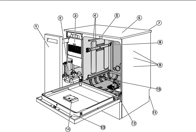
Machine overview
aSide unit
bDispensing containers for process chemicals
cDrying unit
dRails for baskets and mobile units
eDoor lock
fTest point for performance checks (Top, front right; only visible with lid removed)
gModule slot for a communication module (Back, top right)
hUpper machine spray arm
iWater connections for mobile units and baskets
jLower machine spray arm
kRear of the machine:
–Second data plate
–Electrical and water connections
lFilter combination
mData plate
nReservoir for reactivation salt
17
Product description
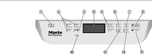
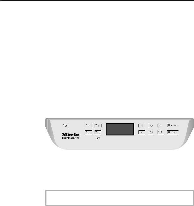
Control panel
aOn/off button
For switching the machine on and off.
b, , and buttons
Program selection buttons.
The button assignment can be configured.
cProgram list button
For accessing the list of all additional programs.
dDisplay
User interface and program sequence display.
eand arrow buttons
For navigating in the user interface.
fCancel button
For canceling a process in the user interface. No program interruption.
gSettings button
For accessing the system settings menu.
hStart/Stop button
For starting or canceling a program.
iDoor release button
For opening the door before or after a program sequence.
jDrying button
For switching drying on and off.
kOK button
For selecting or confirming entries in the user interface (acknowledge or save).
lService interface
Testing and transmission point for the Miele Service.
18

Product description
LEDs in the buttons
The buttons on the control panel have LEDs that indicate the status of the machine.
|
Button |
LED |
Status |
|
|
Button |
ON |
The machine is switched on. |
|
|
FLASHES |
The machine is ready for use. |
||
|
OFF |
The machine is switched off. |
||
|
Program selec- |
ON |
The respective program has been selected. At the |
|
|
tion buttons |
end of the program the LED will remain lit until a dif- |
||
|
, and |
ferent program is selected. |
||
|
OFF |
The program is not selected or the program settings |
||
|
are being selected. |
|||
|
Button |
ON |
A program has been selected from the program list. |
|
|
At the end of the program the LED will remain lit until |
|||
|
a different program is selected. |
|||
|
OFF |
No program has been selected from the list or the |
||
|
program settings are being selected. |
|||
|
Button |
ON |
The additional “Drying” function has been activated |
|
|
for the selected program (not available for all pro- |
|||
|
grams; see “Program chart”). |
|||
|
OFF |
The additional “Drying” function has been deacti- |
||
|
vated. |
|||
|
Start/Stop |
ON |
A program is running. |
|
|
button |
|||
|
FLASHES |
A program has been selected, but has not yet |
||
|
GREEN |
started. |
||
|
FLASHES RED |
A fault has occurred (see “Frequently asked ques- |
||
|
tions”). |
|||
|
OFF |
A program has finished. |
||
|
Button |
ON |
The door is closed (locked) and there is no program |
|
|
running. |
|||
|
FLASHES |
A program has finished and the door is closed |
||
|
(locked). |
|||
|
OFF |
A program is running or the door is open (unlocked). |
||
19
Operation
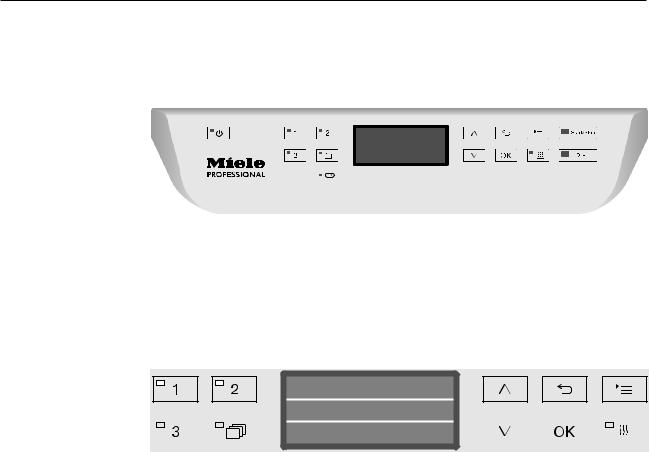
Control panel
The machine is operated exclusively by the buttons located on the stainless steel surfaces on either side of the display. The display is not a touch screen.
A light touch on the relevant button is sufficient to operate the functions. The buttons can also be pressed and held for approx. 20 seconds.
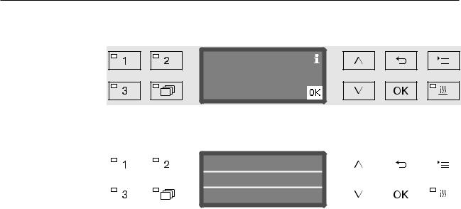
Display illustrations
All display illustrations shown in these operating instructions are examples which can be different from the actual display screens shown.
Normal plus
|
Temperature |
75 °C |
||||||||||||||
|
Duration |
1:30 h |
||||||||||||||
The control buttons are shown next to the display. The , and
Start/Stop buttons are not shown.
20
![]()
Operation
Switching on
The machine must be connected to the electrical supply.
Press the button until the button’s LED lights up.
After that, the display shows the following:
PG 8583 CD
As soon as the machine is ready for operation, the display changes to show the last selected program, e.g.:
Normal plus
|
Temperature |
75 °C |
||||||||||||||
|
Duration |
1:30 h |
||||||||||||||
If the machine is being used for the first time, or if the factory default settings have been reinstated, some basic parameters, e.g., language, date, time, etc., must first be set. To enable this, the display automatically changes to the relevant screen.
Switching off
Press the button.
Auto-off function
To save energy, the machine has an Auto-off function. If the machine has not been used for a specific time period, it switches itself off automatically; see “Additional settings/Switch off after”.
Use the button to switch the machine on again.
Ready for operation (standby)
When it is ready for use (standby), the machine remains switched on, the button flashes, and the time is shown on the display. Pressing any button reactivates the machine. Standby can be switched on and off as required; see “Additional settings/Switch off after”.
21

Operation
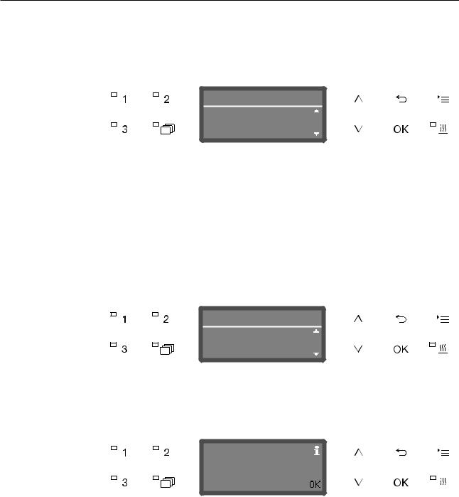
Display interface
The machine is controlled by menus. The menus are displayed in a 3- line display on the control panel.
The name of the menu (top line) and up to two options are shown.
The currently selected option is highlighted, e.g.
Settings
Language
Date
Menu operation |
|
|
Settings button |
|
|
For accessing the system settings menus. |
|
|
and |
Arrow buttons |
|
The arrow buttons are used to navigate up and down by row within a |
|
|
menu. Press and hold the button to automatically scroll through the |
|
|
list to the end of the menu. Press the button again to continue navi- |
|
|
gating. |
|
|
Parameter values can also be altered in defined increments using the |
|
|
arrow buttons. Instructions for this can be found in the relevant sec- |
|
|
tions. |
|
|
OK |
OK button |
|
The OK button is used for confirming (acknowledging) a selection or |
|
|
for saving input. The display then moves to the next menu or, when |
|
|
entering parameter values, to the next input position. Instructions for |
|
|
this can be found in the relevant sections. |
|
|
Cancel button |
|
|
Before the OK button has been pressed, a process can be canceled |
|
|
at any time by pressing the button. The display changes to the |
|
|
next menu level up. Any setting changes made will not be saved. |
22

Operation
Settings in the menu
All menu descriptions in these operating instructions are structured as follows:
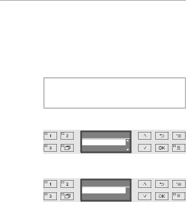
Input procedure The input procedure describes the complete sequence required to reach a particular menu level. The menu options shown must be selected individually using the arrow buttons and then confirmed with
OK.
Example:
Display view
Example:
Button
Settings
Time of day
Time format
If a menu level is already displayed, the path does not need to be followed completely. If, for example, the Settings menu is already displayed, you do not need to press the button again. In this case, simply follow the sequence from Settings onwards.
When selecting a menu, the last menu used is generally pre-selected.
Time format
12 h
24 h
Options |
All available setting options are listed with a short description. |
|
Example: |
— |
12 h |
|
Time of day display in 12-hour format (am/pm). |
||
|
— |
24 h |
|
|
Time of day display in 24-hour format. |
||
Method |
After that, further instructions are provided. |
|
Example: |
Select an option using the and arrow buttons. |
|
|
Press OK to save the setting. |
23
Operation
Symbols in the display |
|||||||||||||||||
|
Navigation arrows |
|||||||||||||||||
|
If a menu consists of more than two options, two navigation arrows |
|||||||||||||||||
|
are shown at the side of the menu options. |
|||||||||||||||||
|
Settings |
|||||||||||||||||
|
Language |
|||||||||||||||||
|
Date |
|||||||||||||||||
|
Use the and arrow buttons on the control panel to navigate |
|||||||||||||||||
|
through the menu. |
|||||||||||||||||
|
— — — — — — |
Dotted line |
||||||||||||||||
|
If a menu contains more than two options, the end of the option list is |
|||||||||||||||||
|
marked by a dotted line. The last entry appears above the line, the |
|||||||||||||||||
|
first entry below it. |
|||||||||||||||||
|
Check |
|||||||||||||||||
|
If there are several options available, the current setting is marked |
|||||||||||||||||
|
with a check . |
|||||||||||||||||
|
Language |
|||||||||||||||||
|
english (GB) ( |
|||||||||||||||||
|
english (USA) |
|||||||||||||||||
|
System messages |
|||||||||||||||||
|
The symbol denotes system messages. These give information, |
|||||||||||||||||
|
such as a notification of an excessively low level in the supply con- |
|||||||||||||||||
|
tainers or a reminder for the next service. |
|||||||||||||||||
|
Refill salt |
|||||||||||||||||
|
System messages are displayed at the start and end of a programme |
|||||||||||||||||
|
and have to be confirmed (acknowledged) individually with OK or all |
|||||||||||||||||
|
together at the end of the programme by opening the door. If the |
|||||||||||||||||
|
symbol is shown on the display, the system messages can be |
|||||||||||||||||
|
opened by pressing the OK button. |
|||||||||||||||||
|
Fault messages |
|||||||||||||||||
|
In the event of a fault, a warning triangle is shown in place of the |
|||||||||||||||||
|
symbol. See “Problem solving guide” and “After sales service” for |
|||||||||||||||||
|
more information. |
24
Settings
Additional settings
Commissioning
Installation and connection
Before commissioning, the machine must be securely installed, and the water inlet and drain hoses and the power cord correctly connected. See “Installation,” “Water connection,” and “Electrical connection” and the installation plan supplied.
Procedure
During commissioning, a set procedure is followed which must not be interrupted, e.g. by opening the door. The display will automatically guide you through the process.
All settings, except for selecting the water connections, can be retro-
spectively altered via the and menus.
The settings made during the commissioning process are only adopted after a complete program has been run.
If the program is interrupted or if no program is started or the machine is switched off, the commissioning process must be carried out again.
Turning on the Press the button until the LED on the keypad lights up. machine
Selecting the The commissioning process starts with selecting the language.
language
Language
english (GB) (
english (USA)
Use the and arrow buttons to select the language you want and hit OK to save.
Selecting the The menu for selecting the temperature unit will then appear.
temperature unit
Temperature unit
°C
°F
Use the and arrow buttons to select the temperature unit you want and hit OK to save.
25
Commissioning
Selecting the The menu for selecting the date format will then appear.
date format
Date format
DD:MM:YY
MM:DD:YY
—DD = day
—MM = month
—YY = year.
Use the and arrow buttons to select the date format you want and press OK to save.
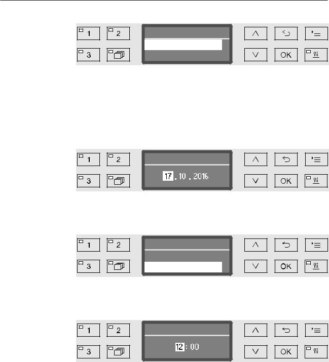
Setting the date The menu for setting the date will then appear.
Date
Use the and arrow buttons to set the day, month, and year and press OK to save each one.
Selecting the The menu for selecting the clock format will then appear.
clock format
Time format
12 h
24 h
Use the and arrow buttons to select the clock format you want and hit OK to save.
Setting the The menu for setting the display for the time of day will then appear.
clock
Time of day
Use the and arrow buttons to select the hours and minutes and hit OK to save each one.
26
|
Commissioning |
|||||||||||||||||||
|
Setting the |
The menu for setting the water hardness will then appear. |
||||||||||||||||||
|
water hardness |
|||||||||||||||||||
|
Water hardness |
|||||||||||||||||||
|
level |
|||||||||||||||||||
|
19 |
°dH |
||||||||||||||||||
|
(0 — 70 °dH) |
|||||||||||||||||||
|
The possible range is shown in the bottom line of the display. Water |
|||||||||||||||||||
|
hardness setting values can be found in the “Water softener/Settings” |
|||||||||||||||||||
|
chart. |
|||||||||||||||||||
|
Your local water authority can give you information about the exact |
|||||||||||||||||||
|
water hardness in your area. |
|||||||||||||||||||
|
With varying water hardness, always set the highest level. If the water |
|||||||||||||||||||
|
hardness fluctuates between, for instance, 8 and 18 gr/gal (8 and 17 |
|||||||||||||||||||
|
°dH), the water hardness must be set to 18 gr/gal (17 °dH). |
|||||||||||||||||||
|
Set the water hardness using the arrow buttons (higher) and |
|||||||||||||||||||
|
(lower) and press OK to save. |
|||||||||||||||||||
|
Write down the water hardness as described in “Water softener/ |
|||||||||||||||||||
|
Water hardness”. |
|||||||||||||||||||
|
Selecting water |
The menu for setting water connections will then appear. |
||||||||||||||||||
|
connections |
Unused water connections, e.g., if there is only one connection, can |
||||||||||||||||||
|
be deactivated here. |
|||||||||||||||||||
|
Following commissioning, the water connections can be reinstated |
|||||||||||||||||||
|
by Miele Service. |
|||||||||||||||||||
|
Plumbing connections |
|||||||||||||||||||
|
Accept |
|||||||||||||||||||
|
Cold water |
|||||||||||||||||||
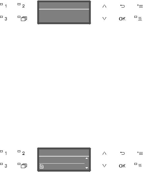
The water connection is set via multiple choice. A box is shown in the display next to all water connections. If the connection is activated, a check is displayed. Select to activate or deactivate the water connections.
Use the and arrow buttons to select the proper plumbing connections. Water connections are activated or deactivated by pressing OK.
To save the selection, select the Accept option at the end of the list and confirm with OK.
27
Commissioning
Commissioning Commissioning is completed when the following message is discompleted played.
Set up successful
Confirm the message with OK. The machine is now ready for use.
|
Normal plus |
||||||||||||||
|
Temperature |
||||||||||||||
|
75 °C |
||||||||||||||
|
Duration |
1:30 h |
|||||||||||||
|
The settings made during the commissioning process are only |
|||||
|
adopted after a complete program has been run. |
|||||
|
Select any program, e.g.: Drain. |
|||||
|
Press the Start/Stop button to start the program. |
|||||
|
After commissioning, every program starts with reactivation of the |
|||||
|
water softener. |
|||||
|
Fault 420 |
|||||
|
If the program is canceled using Fault 420, all the plumbing connec- |
|||||
|
tions are deactivated. |
|||||
|
Confirm the error message with OK. |
|||||
|
Use the button to switch the machine off. |
|||||
|
Wait approximately 10 seconds before switching the machine on |
|||||
|
again with the button. |
|||||
|
The commissioning procedure starts again. |
|||||
|
Perform commissioning and activate at least one plumbing connec- |
|||||
|
tion; e.g. for cold water. |
28
Opening and closing the door
Electronic door lock
The machine is equipped with a Comfort door lock. When the door is closed, the Comfort door lock automatically pulls the door into the correct position, electronically locking the door.
Opening the door
An electronically locked door can only be opened if:
—the machine is connected to the electrical supply and is switched on (the LED for the button is lit up)
—there is no program running
—the temperature in the wash cabinet is less than 140°F (60°C)
—the LED is lit up.
Press the button to open the door.
The Comfort door lock opens the door slightly. The LED goes out as soon as the door is unlocked.
The control panel of the machine is also a door handle.
Grasp the handle underneath the control panel and lower the door to open it.
Closing the door
Ensure that there are no objects or items in the load obstructing the door.
Do not touch the door frame.
Risk of injury!
Lift the door until it engages with the door lock. The door is automatically pulled into the correct position by the Comfort door lock.
29
Opening and closing the door
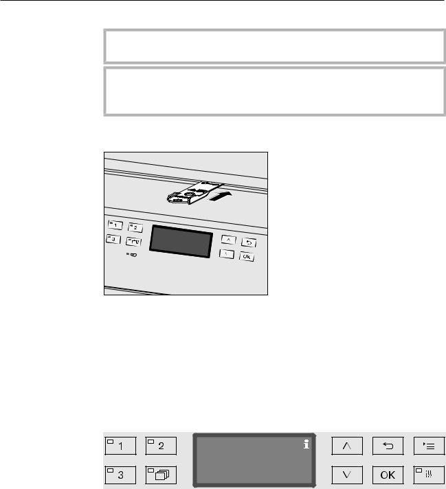
Opening the door using the emergency release
The emergency release may only be used when it is no longer possible to open the door normally, e.g. in the event of power loss.
If the emergency release is operated during a program cycle, hot water and cleaning agents can escape.
Risk of scalding, burning and chemical burns.
Push against the door so that less force is needed to operate the emergency release.
Push the tool supplied in the accessory pack horizontally into the gap between the door and the lid or countertop. The right-hand edge of the tool must align with the outer right-hand edge of the display.
Press against the unlocking mechanism with the tool until you hear the door unlock. The door can now be opened.
If the machine is switched on, the activation of the emergency release will be recorded in the process documentation and the following message will appear in the display:
Emergency release
The message remains in the display until the door is closed. It is not recorded if the machine is switched off.
30
![]()
Water softener
Water hardness
In order to achieve good cleaning results, the machine needs to operate with soft water. Hard water results in the build-up of calcium deposits on the load and in the machine.
Mains water with a water hardness of 4 gr/gal (4 °dH) must be softened. This occurs automatically in the built-in water softener.
The water softener must be set to the exact hardness of the mains water (see “Water softener/Setting the water hardness”).
Your local water authority can give you information about the exact water hardness in your area.
It is useful to know your water hardness so that you can provide the service technician with this information in the event of any subsequent service calls. For this reason, record the hardness of the mains water here:
________________________gr/gal or °dH
The water softener must be reactivated at regular intervals. This requires special reactivation salt (see “Water softener/Filling the salt reservoir”). Reactivation is carried out automatically during a program sequence.
If the hardness level of your water is constantly less than 4 gr/gal (= 4 °dH), salt is not required for the water softener. The water hardness level must, however, still be set.
31

Water softener
Setting the water hardness level
Water hardness can be set between 0 and 70 gr/gal (0 — 70 °dH).
Open the menu as follows:
button
Additional settings
Water hardness
Water hardness
19 °dH
(0 — 70 °dH)
The bottom line of the display shows the possible input range. Water hardness input values can be found in the chart on the next page.
Where the water hardness fluctuates, e.g. between 8 — 18 gr/gal (8 — 18 °dH), always program the machine to the higher value, 18 gr/gal (18 °dH) in this example.
Set the water hardness level using the arrow buttons ( = higher and = lower).
Press OK to save the setting.
32

Water softener
Settings table
|
gr/gal |
ppm |
mmol/l |
Display |
|
CaCO3 |
|||
|
0 |
0 |
0 |
0 |
|
1 |
20 |
0.2 |
1 |
|
2 |
40 |
0.4 |
2 |
|
3 |
50 |
0.5 |
3 |
|
4 |
70 |
0.7 |
4 |
|
5 |
90 |
0.9 |
5 |
|
6 |
110 |
1.1 |
6 |
|
7 |
130 |
1.3 |
7 |
|
8 |
140 |
1.4 |
8 |
|
9 |
160 |
1.6 |
9 |
|
10 |
180 |
1.8 |
10 |
|
11 |
200 |
2.0 |
11 |
|
12 |
220 |
2.2 |
12 |
|
13 |
230 |
2.3 |
13 |
|
14 |
250 |
2.5 |
14 |
|
15 |
270 |
2.7 |
15 |
|
16 |
290 |
2.9 |
16 |
|
17 |
310 |
3.1 |
17 |
|
18 |
320 |
3.2 |
18 |
|
19 |
340 |
3.4 |
19 *) |
|
20 |
360 |
3.6 |
20 |
|
21 |
380 |
3.8 |
21 |
|
22 |
400 |
4.0 |
22 |
|
23 |
410 |
4.1 |
23 |
|
24 |
430 |
4.3 |
24 |
|
25 |
450 |
4.5 |
25 |
|
26 |
470 |
4.7 |
26 |
|
27 |
490 |
4.9 |
27 |
|
28 |
500 |
5.0 |
28 |
|
29 |
520 |
5.2 |
29 |
|
30 |
540 |
5.4 |
30 |
|
31 |
560 |
5.6 |
31 |
|
32 |
580 |
5.8 |
32 |
|
33 |
590 |
5.9 |
33 |
|
34 |
610 |
6.1 |
34 |
|
35 |
630 |
6.3 |
35 |
*) Factory default setting
|
gr/gal |
ppm |
mmol/l |
Display |
|
CaCO3 |
|||
|
36 |
650 |
6.5 |
36 |
|
37 |
670 |
6.7 |
37 |
|
38 |
680 |
6.8 |
38 |
|
39 |
700 |
7.0 |
39 |
|
40 |
720 |
7.2 |
40 |
|
41 |
740 |
7.4 |
41 |
|
42 |
760 |
7.6 |
42 |
|
43 |
770 |
7.7 |
43 |
|
44 |
790 |
7.9 |
44 |
|
45 |
810 |
8.1 |
45 |
|
46 |
830 |
8.3 |
46 |
|
47 |
850 |
8.5 |
47 |
|
48 |
860 |
8.6 |
48 |
|
49 |
880 |
8.8 |
49 |
|
50 |
900 |
9.0 |
50 |
|
51 |
920 |
9.2 |
51 |
|
52 |
940 |
9.4 |
52 |
|
53 |
950 |
9.5 |
53 |
|
54 |
970 |
9.7 |
54 |
|
55 |
990 |
9.9 |
55 |
|
56 |
1000 |
10.0 |
56 |
|
57 |
1020 |
10.2 |
57 |
|
58 |
1040 |
10.4 |
58 |
|
59 |
1060 |
10.6 |
59 |
|
60 |
1070 |
10.7 |
60 |
|
61 |
1090 |
10.9 |
61 |
|
62 |
1110 |
11.1 |
62 |
|
63 |
1130 |
11.3 |
63 |
|
64 |
1150 |
11.5 |
64 |
|
65 |
1160 |
11.6 |
65 |
|
66 |
1180 |
11.8 |
66 |
|
67 |
1200 |
12.0 |
67 |
|
68 |
1220 |
12.2 |
68 |
|
69 |
1240 |
12.4 |
69 |
|
70 |
1250 |
12.5 |
70 |
33

Water softener
Filling the salt container
Use only special, coarse-grained reactivation salt with a granule size of approx. 1/16“ — 3/16” (1 — 4 mm).
Do not under any circumstances use other types of salt such as table salt, agricultural or gritting salt. These may contain insoluble additives which can impair the functioning of the water softener.
Reactivation salt is available from Miele, please contact Miele for ordering. See last page for contact information.
Inadvertently filling the salt reservoir with cleaning agent will cause serious damage to the water softener.
Before filling the salt reservoir make sure that you have picked up the right packet of reactivation salt.
Open the door to an angle of around 45°. This ensures that the salt flows into the container more easily.
Press the yellow button with the symbol on the salt container in the direction of the arrow. The flap will spring open.
Open the funnel.
The container takes approx. 3-4.5 lb (1.4–2 kg) of salt, depending on the type of salt and the remaining fill level.
34

Water softener
Never fill the container with water.
The container could overflow when filled with salt.
Add salt into the container until the funnel is full but still closes easily. Do not add any more than 2 kg of salt.
As the salt container is being filled, displaced water (brine) may run
out.
Clean any excess salt from around the opening of the container, focusing especially on the container’s seal. Do not use running water to rinse away salt residues as this can cause the container to overflow.
Close the container.
Do not force the container shut if it has been overfilled.
If an overfilled salt container is forced shut, this may damage the container.
Remove excess salt before closing the container.
Run the Rinse program after refilling salt.
This will ensure that any traces of salt and brine are dissolved, diluted, and rinsed away.
Excess salt and brine which has overflowed can cause corrosion damage if they are not rinsed away.
35

Water softener
Salt refill reminder
If the salt level in the reservoir is low, the following reminder will appear:
Refill salt
Confirm the message with the OK button.
Fill the reservoir as described.
When the message first appears, there may be sufficient salt for a further program, depending on the water hardness level set.
If there is no saline solution left in the water softener, a relevant message will appear in the display and the machine will be locked for further use.
The machine can be used again a few seconds after the salt has been refilled.
36

Application technology
Mobile units, baskets, modules and inserts
This machine can be equipped with an upper and lower basket or a mobile unit which can be fitted with different inserts and modules or exchanged for special accessories depending on the items to be washed.
Select accessories which are appropriate for the application.
Information on the individual areas of application can be found on the following pages, as well as in the operating instructions for the mobile units, baskets, modules and inserts (if available).
For all areas of application defined in “Intended use” Miele offers suitable accessories such as mobile units, baskets, modules, inserts and special fittings. Contact Miele for more information.
Water supply Mobile units and baskets with spray arms and injectors are equipped with one or more connection points to the water supply. When loading baskets, mobile units, etc. into the machine, connect these to the water connection points in the back panel of the wash cabinet. The mobile units and baskets are held in place by the wash cabinet door when closed.
Any free connections in the back panel are closed mechanically.
Older models of Only use older models of mobile units and baskets in this machine in mobile units and consultation with Miele. In particular mobile units and baskets with baskets water supply pipes for spray arms and injector manifolds must be
converted to the new type of water connector.
Conversion must be carried out by Miele Service and is only available for selected basket models.
The assembly of connectors for the water supply of mobile units and baskets must be carried out by Miele Service.
Fitting faults on mobile units and baskets can cause damage to the machine.
Following conversion, mobile units and baskets can no longer be used in older models.
37

Application technology
Adjusting the height of the upper basket
Height-adjustable upper baskets can be adjusted between three positions with 3/4″ (2 cm) between each position to accommodate items of different heights.
To adjust the height, the brackets with rollers on the side of the upper basket and the water connector at the back of the basket have to be moved. The roller brackets are each secured to the upper basket by two screws. The water connector consists of the following components:
—A stainless steel plate with 2 openings
—A plastic connection piece
—6 screws.
Only adjust the upper basket horizontally. The baskets are not designed to be positioned on a slant (one side up, one side down). Altering the height will alter loading heights for both the upper and lower baskets.
To adjust the upRemove the upper basket by pulling it out until a resistance is felt per basket: and lifting it off the runners.
Unscrew the roller brackets and the water connector.
To adjust the upper basket to the …
… upper position:
Move the roller brackets on both sides to the lower position and secure them firmly.
Position the stainless steel plate over the openings in the water supply pipe so that the upper opening is covered. Secure the stainless steel plate at the top with 2 screws. Place the water connector in the lower opening of the stainless steel plate so that the middle opening is covered. Secure the water connector with 4 screws.
38

Application technology
… middle position:
Move the roller brackets on both sides to the middle position and secure them firmly.
Position the stainless steel plate over the openings in the water supply pipe so that one of the outer openings are covered. Secure the stainless steel plate at the top or bottom with 2 screws. Place the water connector in the middle opening of the stainless steel plate so that the outer opening is covered. Secure the water connector with 4 screws.
… lower position:
Move the roller brackets on both sides to the top position and secure them firmly.
Position the stainless steel plate over the openings in the water supply pipe so that the lower opening is covered. Secure the stainless steel plate at the bottom with 2 screws. Place the water connector in the upper opening of the stainless steel plate so that the middle opening is covered. Secure the water connector with 4 screws.
Then check: Put the upper basket back on the rails and push it in carefully to
check that the water connection is positioned correctly.
39

Application technology
Preparing the load
Only items which have been declared by their manufacturer as suitable for machine reprocessing may be processed. The manufacturer’s specific reprocessing instructions must be observed.
Special injector nozzles, irrigation sleeves or adapters may be required for appropriate internal cleaning, depending on the load. These, together with other accessories, are available from Miele.
—Arrange the wash load so that water can access all surfaces. This ensures that it gets properly cleaned!
—Do not place items to be cleaned inside other pieces where they may be concealed.
—Hollow items must be thoroughly cleaned, internally and externally.
—Ensure that items with long narrow hollow sections can be flushed through properly before placing them in a fitting or when connecting them to a water connection.
—Hollow vessels should be inverted and placed in the correct mobile units, baskets, modules and inserts to ensure that water can flow in and out of them unrestricted.
—Deep-sided items should be placed at an angle to make sure water runs off them freely.
—Tall, narrow, hollow items should be placed in the center of the baskets or units if possible to ensure better water coverage. or units if possible to ensure better water coverage.
—Take apart any items which can be dismantled according to the manufacturer’s instructions and process the individual parts separately from each other.
—Lightweight items should be secured with a cover net (e.g. an A 6) and small items placed in a mesh tray to prevent them blocking the spray arms.
—The spray arms must not be blocked by items which are too tall or which hang down in their path.
—Broken glass can result in serious injury when loading or unloading. Broken glass items must not be processed in the machine.
—Nickeland chrome-plated items and items made of aluminum require special procedures and are not generally suitable for machine reprocessing. are not generally suitable for machine reprocessing.
—When cleaning items that are made entirely or partially out of plastic , the maximum thermal stability of the item must be considered. Select an appropriate program or adjust the temperature of the program accordingly.
Observe the further information given in the following sections as
necessary depending on the area of application.
40
![]()
Application technology
Preparing the Empty all items before loading them into the machine.
load
Remove non-water soluble residues such as paint, adhesives and polymer compounds using appropriate solvents.
Rinse wash load items which have been in contact with solvents, chloride solutions or hydrochloric acid thoroughly with water and drain well before loading into the machine.
The amount of residual solvents and acids on items going into the cabinet should be minimal.
There should be no more than a trace of any solvents with a flash point of below 70°F (21°C).
Chloride solutions, in particular hydrochloric acid, must not be placed in the cabinet.
Scoop nutrient media (Agar) out of petri dishes.
Shake out any blood residues and remove any clots.
If necessary rinse the wash load briefly with water to prevent coarse soiling entering the machine.
Remove all stoppers, corks, labels, sealing wax residue, etc.
Secure small items, such as stoppers and taps in suitable baskets for small items.
It may be necessary in individual cases to check whether extremely stubborn contamination, e.g., vacuum grease, paper labels, etc., which could affect the cleaning result, must be removed in advance.
It must be determined whether wash load items which are contaminated with microbiological material, pathogenic germs, facultative pathogenic bacteria, genetically modified material, etc. need to be sterilized prior to machine reprocessing.
41

Application technology
Carry out a visual check before starting every program:
—Is everything correctly loaded/connected for cleaning?
—Was the recommended loading template followed?
—Can the lumen/narrow sections of hollow items be accessed by the wash fluid?
—Are the spray arms clean and do they rotate freely?
—Are the filters clean?
Remove any coarse soiling and clean them if necessary.
—Are the removable modules, injector nozzles, irrigation sleeves and other rinsing fittings securely connected?
—Are the baskets and modules or mobile units correctly connected to the water supply and are the water connectors undamaged?
—Are all process chemical containers sufficiently filled?
The following must be checked at the end of every program:
—Carry out a visual check of the load for cleanliness.
—Check that all hollow items are still securely located on their injector nozzles.
Any hollow items that have become disconnected from their fittings during reprocessing must be re-processed.
—Check that the lumen of hollow items are free of obstruction.
—Check that injector nozzles and connectors are securely held in position in the baskets or inserts.
42

Application technology
Wash load…
…wide-neck Wash load items with wide necks, e.g. beakers, wide neck Erlenmeyer flasks and petri dishes, or cylindrical items, e.g. test tubes, can be cleaned inside and out by rotating spray arms.
To do this the wash load is positioned in full, half or quarter inserts and placed in an empty lower basket or an upper basket with a spray arm.
…narrow-neck Baskets with special injector modules are available for wash load items with narrow necks, e.g. narrow neck Erlenmeyer flasks, round bottomed flasks and measuring flasks.
The injector units and modules come with their own operating instructions.
When loading please note:
—Place petri dishes or similar items in the appropriate insert with the dirty side facing towards the middle.
—Place pipettes with the pointed end facing downwards.
—Quarter segment inserts should be positioned at a minimum 1″ (3 cm) distance from the edge of the upper or lower basket.
—Position quarter segment inserts for test tubes around the middle to leave the corners of the upper or lower basket free.
—Use a cover net to avoid breakages if required.
43

Chemical processes and technology
In this section, you will find a description of the causes of common chemical reactions which can occur between different types of soiling, process chemicals, and the components of the machine, along with their remedies as necessary.
This section is intended as a guide. If unforeseen interactions occur during reprocessing or if you have any queries on this subject, please seek advice from Miele.
General information
|
Problem |
Solution |
|
|
If elastomers (hoses and seals) and plastics |
— Determine and remedy the causes of the |
|
|
in the machine are damaged, for example |
damage. |
|
|
by swelling, shrinking, hardening, or brittle- |
See information regarding “Associated |
|
|
ness of materials, tears, and cracks, com- |
||
|
process chemicals”, “Soiling”, and “Reac- |
||
|
ponents will not function correctly and this |
||
|
tion between process chemicals and soil- |
||
|
generally leads to leaks. |
||
|
ing” in this section. |
||
|
A heavy build-up of foam during the pro- |
— Determine and remedy the causes of the |
|
|
gram sequence will impair the cleaning and |
foam. |
|
|
rinsing effect on the wash items. Foam es- |
— Check the process used regularly to mon- |
|
|
caping from the wash cabinet can cause |
||
|
itor foaming levels. |
||
|
damage to the machine. |
||
|
See information regarding “Associated |
||
|
When foam develops, the cleaning process |
||
|
is not standardized or validated in principle. |
process chemicals”, “Soiling”, and “Reac- |
|
|
tion between process chemicals and soil- |
||
|
ing” in this section. |
||
|
Corrosion to stainless steel in the wash |
— Determine and remedy the causes of cor- |
|
|
cabinet and to accessories can give them a |
rosion. |
|
|
different appearance: |
See information regarding “Associated |
|
|
— rust (red marks/discoloration) |
||
|
process chemicals”, “Soiling”, and “Reac- |
||
|
— black stains/discoloration |
tion between process chemicals and soil- |
|
|
ing” in this section. |
||
|
— white stains/discoloration (etched surface) |
||
|
Corrosive pitting can lead to the machine |
||
|
not being water-tight. Depending on the ap- |
||
|
plication, corrosion can affect cleaning and |
||
|
rinsing results (laboratory analysis) or cause |
||
|
corrosion to (stainless steel) wash items. |
||
44

Chemical processes and technology
Associated process chemicals
|
Problem |
Solution |
|
|
The ingredients in process chemicals have |
— Follow the process chemical manufac- |
|
|
a significant impact on the longevity and |
turer’s instructions and recommendations. |
|
|
functionality (throughput) of dispensing sys- |
— Carry out a regular visual check of the |
|
|
tems. |
dispensing system (suction wands, hoses, |
|
|
dispensing canisters, etc.) for any dam- |
||
|
age. |
||
|
— Regularly check the flow rate of the dis- |
||
|
pensing system. |
||
|
— Ensure that the regular cycle of mainte- |
||
|
nance is observed. |
||
|
— Please contact Miele for advice. |
||
|
Process chemicals can damage elastomers |
— Follow the process chemical manufac- |
|
|
and plastics in the machine and acces- |
turer’s instructions and recommendations. |
|
|
sories. |
— Carry out a regular visual check of any ac- |
|
|
cessible elastomers and plastics for dam- |
||
|
age. |
||
|
Hydrogen peroxide can release large |
— Only use validated processes. |
|
|
amounts of oxygen. |
— The wash temperature must be lower than |
|
|
158°F (70°C) when using hydrogen perox- |
||
|
ide. |
||
|
— Please contact Miele for advice. |
||
|
The following process chemicals can cause |
— The process parameters in the wash pro- |
|
|
large amounts of foam to build up: |
gram, such as dispensing temperature, |
|
|
— cleaning agents and rinsing agents con- |
dosage concentration, etc., must be set |
|
|
to ensure the whole process is foam-free |
||
|
taining surfactants |
||
|
or very low-foaming. |
||
|
Foam can occur: |
||
|
— Please observe the process chemical |
||
|
— in the program phase in which the |
||
|
manufacturer’s instructions. |
||
|
process chemical is dispensed |
||
|
— in the following program block if it has |
||
|
been spilt |
||
|
— in the following program with rinsing |
||
|
agent if it has been spilt |
||
45

Chemical processes and technology
Associated process chemicals
|
Problem |
Solution |
|
|
De-foaming agents, especially silicone- |
— De-foaming agents should be used in ex- |
|
|
based ones, can cause the following: |
ceptional cases only; for instance, when |
|
|
— a build-up of deposits in the wash cabinet |
absolutely essential for the process. |
|
|
— a build-up of deposits on the wash items |
— The wash cabinet and accessories should |
|
|
be periodically cleaned without wash |
||
|
— damage to elastomers and plastics in the |
||
|
items and without de-foaming agent using |
||
|
cleaning machine |
||
|
the Organic program. |
||
|
— damage to certain plastics (e.g., polycar- |
— Contact Miele for advice. |
|
|
bonate and plexiglass) in the wash items |
||
|
Soiling |
||
|
Problem |
Solution |
|
|
The following substances can damage elas- |
— Depending on usage, wipe the lower door |
|
|
tomers (hoses and seals) and plastics in the |
seal on the cleaning machine periodically |
|
|
cleaning machine: |
with a lint-free cloth or sponge. Clean the |
|
|
— oil, wax, aromatic and unsaturated hydro- |
wash cabinet and accessories without |
|
|
wash items using the Organic program. |
||
|
carbons |
||
|
— emollients |
— Reprocess the wash items using the Oil |
|
|
program program (where this is available) |
||
|
— cosmetics, hygiene and skincare products |
||
|
or use a special program that dispenses |
||
|
such as creams (analytical applications, |
||
|
cleaning agents containing tensides. |
||
|
filling) |
||
|
The following substances can lead to a |
— Thoroughly rinse wash items in water be- |
|
|
heavy build-up of foam during washing and |
forehand. |
|
|
rinsing: |
— Select a cleaning program with at least |
|
|
— some disinfection agents, dishwashing |
||
|
one short pre-wash in cold or hot water. |
||
|
cleaning agents, etc. |
— Depending on the application, use de- |
|
|
— reagents for analysis, e.g., for microtiter |
||
|
foaming agents that do not contain sili- |
||
|
plates |
cone oils. |
|
|
— cosmetics, hygiene and skincare products |
||
|
such as shampoos and creams (analytical |
||
|
applications, filling) |
||
|
— active foaming agents such as surfactants |
||
46

Chemical processes and technology
Soiling
|
Problem |
Solution |
|
|
The following substances may cause corro- |
— Thoroughly rinse wash items in water be- |
|
|
sion to stainless steel in the wash cabinet |
forehand. |
|
|
and on accessories: |
— Put the drip-dry items to be washed into |
|
|
— hydrochloric acid |
||
|
the mobile units, baskets, modules, and |
||
|
— other substances containing chlorides, |
inserts and start a reprocessing program |
|
|
as soon as possible after placing in the |
||
|
such as sodium chloride |
||
|
wash cabinet. |
||
|
— concentrated sulphuric acid |
||
|
— chromic acid |
||
|
— particles of iron and shavings |
||
|
Reaction between process chemicals and soiling |
||
|
Problem |
Solution |
|
|
Natural oils and fats can be emulsified with |
— Use the Oil program. |
|
|
alkaline process chemicals. This can lead to |
— This special program dispenses emulsi- |
|
|
a heavy build-up of foam. |
fiers (pH neutral) in the pre-wash. |
|
|
— Depending on the application, use de- |
||
|
foaming agents that do not contain sili- |
||
|
cone oils. |
||
|
Soiling containing high protein levels, such |
— Select a cleaning program with at least |
|
|
as blood, can cause a heavy build-up of |
one short pre-wash in cold water. |
|
|
foam when processed with alkaline process |
||
|
chemicals. |
||
|
Non-precious metals such as aluminum, |
— Please observe the process chemical |
|
|
magnesium, and zinc can release hydrogen |
manufacturer’s instructions. |
|
|
when processed with very acidic or alkaline |
||
|
process chemicals (oxyhydrogen reaction). |
||
47

Adding and dispensing process chemicals
Unsuitable process chemicals pose a health risk.
Using unsuitable process chemicals will generally cause an unsatisfactory wash result and can pose a health risk or cause damage to property.
Only use process chemicals designed specifically for use in laboratory glassware washers and follow the manufacturer’s instructions on how to use them.
Please follow any instructions relating to non-toxic residues.
Process chemicals pose a health risk.
Some process chemicals may be corrosive and irritant.
Observe the relevant safety codes and safety data sheets issued by the process chemical manufacturers when handling process chemicals.
Take all protective measures required by the process chemical manufacturer, e.g., wear protective goggles and protective gloves.
Contact Miele for information about suitable process chemicals.
Highly viscous (thick) process chemicals can affect the dispenser monitoring and lead to inaccurate data. In this instance, please contact Miele Service for advice.
Dispensing systems
The machine is equipped with an internal dispensing systems for process chemicals:
—Neutralization agent
This is dispensed using a siphon.
—Liquid process chemicals This is dispensed via a siphon.
An additional internal dispensing system can be fitted retrospectively by Miele Service if required.
Labeling of the Liquid process chemicals from external containers are dispensed by suction wands suction wands. Color coding the suction wands can be helpful for
correct dispensing.
Miele uses and recommends the following:
|
— Blue: |
For cleaning agents |
|
— Red: |
For neutralizing agents |
|
— Green: |
For chemical disinfection agents or |
|
an additional second cleaning agent |
|
|
— White: |
For acidic process chemicals |
|
— Yellow: |
For free choice |
48

Adding and dispensing process chemicals
Neutralizing agent
Neutralizing agent (pH setting: acidic) neutralizes any residues of alkaline process chemicals on the surface of the load.
Neutralizing agent is dispensed automatically in the Interim rinse phase after the main wash (see “Program charts”). The reservoir must be filled and the dispensing system vented for this to occur.
In the Inorganic program, neutralizing agent is dispensed additionally for an acidic pre-wash.
Replenishing neuOpen the drawer in the side unit.
tralizing agent
Remove the neutralizing agent container (red marking) and place it on the open cabinet door or on a surface which is robust and easy to clean.
Take the lid off the canister and remove the suction wand. Place the suction wand on the open wash cabinet door.
Replace the empty container with a full one.
Push the suction wand into the opening of the container and secure the lid. Observe the color coding.
Feed the suction wand into the container until it reaches the bottom.
Wipe up any spilled process chemical thoroughly.
Place the container back in the drawer in the side cabinet.
Close the drawer. Ensure that the dispensing tubes and cords are not kinked or trapped.
After that, the dispensing system must be primed (see “Settings / Priming DOS”).
49

Adding and dispensing process chemicals
|
Checking con- |
Check consumption regularly by checking the fill levels in the supply |
||||||||||||||
|
sumption |
containers and replace containers in time. |
||||||||||||||
Refill indicator |
When the fill level is low in the DOS 3 supply container for neutralizing |
||||||||||||||
|
agent, you are reminded to refill it. |
|||||||||||||||
|
Refill DOS |
|||||||||||||||
Confirm the message shown with OK and
refill the neutralizing agent as described.
If the container is empty, the machine will be locked against further use.
It will be ready for use again when the supply container has been replaced.
|
Dispensing neu- |
For adjusting dispensing concentration, see “Additional settings/Dis- |
|
tralizing agent |
pensing systems.” |
50
 Loading…
Описание
На данной странице мы представляем вам уникальный товар — моечный лабораторный комплекс PG 8583. Без преувеличения можно сказать, что это техника будущего: сверхсовременная, супернадежная и максимально удобная в процессе эксплуатации. Прибор, имеющий новые функции, а значит, способный расширить возможности вашей лаборатории. Итак, вы можете приобрести моечную машину, которая будет работать лучше, а стоить дешевле.
Основные характеристики моечного комплекса PG 8583:
• При изготовлении используется высокопрочная нержавеющая сталь
• Прибор высокотехнологичен и функционален (Touch-контроль 13 программ)
• Несколько встроенных водопроводов (два для холодной воды, и по одному для горячей и для дистиллированной), диспенсеры для порошкообразных и жидких моющих средств. Все это позволяет сделать процесс мытья посуды безукоризненным
• Подходит для обслуживания лабораторий любого ранга, в том числе и для крупных научно-исследовательских центров
• Полностью исключает загрязнение окружающей среды
• Устройство функционирует в автономном режиме
• Система оснащена высокопроизводительным циркуляторным насосом (Qmax: 400 л/мин)
Автомат PG 8583 не имеет встроенного насоса для подачи дистиллированной воды.
Акция: Снижение цен на автомат для мойки лабораторного стекла PG 8583 в белом корпусе
На выбор два комплекта поставки, в зависимости от назначения и интенсивности работы лаборатории.
По любым вопросам, связанным с данной акцией, а также для подбора и консультации по оборудованию, просим связаться с нами удобным для вас способом, и мы обязательно подберем необходимый именно вам вариант.
Акция действует на следующие готовые решения:
Базовый комплект № PG 8583-01 (miele-pg-8583-01-2021) включает в себя:
(Общая стоимость с учётом скидки составляет 801 992,00 рублей (включая НДС 20%))
Автомат для мойки:
• PG 8583 [WW AD LD], арт. 62858302RU, в белом корпусе
Принадлежности:
• A 102 верхняя корзина со встроенным коромыслом-распылителем
• A 151 нижняя корзина
• AK 12 вставка для размещения посуды (2 штуки)
• E 106 вставка для узкогорлой посуды (2 штуки)
Стартовый комплект специальных моющих средств ProCare Lab:
• 10 AP жидкое щелочное средство для обработки лабораторной посуды
• 30 C нейтрализующее кислотное средство с лимонной кислотой
• Регенерирующая соль
• Ключ для канистр CK DIN51
Продвинутый комплект № PG 8583-02 (miele-pg-8583-02-2021) включает в себя:
(Общая стоимость с учётом скидки составляет 929 912,00 рублей (включая НДС 20%))
Автомат для мойки:
• PG 8583 [WW AD LD], арт. 62858302RU, в белом корпусе
Принадлежности:
• A 102 верхняя корзина
• A 150 нижняя корзина с двумя модульными соединениями
• AK 12 вставка для размещения посуды (2 штуки)
• A 300/3 модуль в комплекте с 8 соплами
• A 301/5 модуль в комплекте с 18 соплами
• A 860 опорные решетки для инжекторных модулей A 300/2 и A 300/3
• A 861 опорные решетки для инжекторных модулей A 301/4 и A 301/5
Стартовый комплект специальных моющих средств ProCare Lab:
• 10 AP жидкое щелочное средство для обработки лабораторной посуды
• 30 C нейтрализующее кислотное средство с лимонной кислотой
• Регенерирующая соль
• Ключ для канистр CK DIN51
Специальное предложение действует до 31 декабря 2021 года. Срок акции может быть изменен по усмотрению организатора.
Список товаров, участвующих в акции и размеры скидок, могут быть изменены в течение действия акции без предварительного уведомления.
Модификации Miele Professional PG 8583:
• PG 8583 RU AW-WW-AD-LD / 62858302RU
• PG 8583 RU AE-WW-AD-PD / 62858302RU
• PG 8583 RU AE-WW-AD-LD / 62858302RU
• PG 8583 RU AE-WW-ADP-LD / 62858302RU
• PG 8583 RU AE-WW-AD-LD-OIL / 62858302RU
Расшифровка аббревиатур:
• AW — Внешряя облицовка белого цвета
• AE — Внешняя облицовка из нержавеющей стали
• WW — Горячая вода
• AD — Дистиллированная вода
• ADP — Встроенный насос для подачи дистиллированной воды
• LD — С жидким дозированнием
• PD — С порошковым дозированием
• OIL — Исполнение для масляных/нефтяных загрязнений
Преимущества Miele Professional PG 8583 по сравнению с моделями предыдущей 7-й версией:
• Увеличенное количество программ, управляемых с дисплея (13 программ):
• Универсальная
• Стандартная
• Интенсивная
• Для очистки от неорганических загрязнений
• Обработка посуды, контактирующей с органическими веществами
• Инжектор Плюс
• Для пипеток
• Для пластиковой посуды
• Мини (короткий цикл — 19 мин)
• Для очистки от масел и нефти
• Охлаждение обработанной посуды от 93 С до 10С
• Промывание обычной водой
• Промывание очищенной водой
• Более бережная и тщательная обработка всех видов лабораторной посуды
• Более рациональное расположение точек подачи воды
• Принципиально новые конструкции омывающих коромысел
• Увеличен объём рабочей камеры, что дает возможность размещать в режиме максимальной загрузки либо 128 ед. лабораторной посуды, либо 98 пипеток.
• Значительно усовершенствованные конструкции корзин-лафетов и более логичное их расположение — вдали от нагревающих элементов. Обратите внимание: в машине для мойки и обработки лабораторной посуды нового поколения PG 8583 нет ни одного нагревающего элемента расположенного внутри моющей камеры! Это полностью исключает расплавления сушащейся пластиковой посуды. Кроме того, новая модульная концепция устройства корзин обеспечивает максимальную гибкость использования пространства. Модули могут быть использованы в различных комбинациях, т. е. конструкция может быть легко изменена в зависимости от потребностей вашей лаборатории в данный момент.
• Аппарат снабжен более функциональным сушильным отделением. Это защищает металлические части от появления пятен и ржавчины.
• Для смягчения водопроводной воды в модели Miele PG 8583 используется более мощная и результативная установка, которая автоматически выбирает оптимальный режим смягчения.
• Более тщательный контроль таких функций, как частота вращения моечного рукава (обеспечивает беспрепятственную очистку и деблокирование моечных рукавов, в случае необходимости) и очистного давления (оно при очистке регулируется чувствительным датчиком, так как избыточное образование пены может явиться причиной сбоя программы).
Если вас заинтересовал наш товар, то просто позвоните нашим консультантам и они ответят на все интересующие вас вопросы. Вы можете быть счастливым обладателем отличной моечной машины, которая, к тому же, обойдется вам дешевле. Ждем вашего звонка!
-
Инструкции по эксплуатации
1

Miele PG 8535 инструкция по эксплуатации
(84 страницы)
- Языки:Русский
-
Тип:
PDF -
Размер:
833.91 KB -
Описание:
Автоматы для мойки и дизинфекции
Просмотр
На NoDevice можно скачать инструкцию по эксплуатации для Miele PG 8535. Руководство пользователя необходимо для ознакомления с правилами установки и эксплуатации Miele PG 8535. Инструкции по использованию помогут правильно настроить Miele PG 8535, исправить ошибки и выявить неполадки.
- Перейти к основному меню (нажмите Enter)
- Перейти к основному содержанию (нажмите Enter)
- Перейти в конец страницы (нажмите Enter)
-

Важная информация
Узнать больше

- В начало страницы
Избранное
0
Miele PG 8581 Стоматологическая термошайба

Технический паспорт
- PG 8581 Моечно-дезинфекционная машина
- PG 8582 Мед
- PG 8583 Машина для мытья лабораторной посуды
Условные обозначения: Обведены жирным шрифтом сокращения:
Требуется подключение
| Электрическое подключение | Voltage (По умолчанию)
Номинальная нагрузка |
2 переменного тока 208 В 60 Гц
6.2 кВт |
2 переменного тока 208 В 60 Гц
6.2 кВт |
|
| PG 8581
PG 8582 |
Рейтинг предохранителя
Минимальное сечение |
2 30 X A
3 × СРГ 10 |
2 30 X A
3 × 5.2 мм² |
|
| Длина электрического шнура (UL 921) с вилкой | ок. 5 футов 9 дюймов | ок. 1.8 м | ||
| Электрическое подключение | NEMA L6-30 | NEMA L6-30 | ||
| Электрическое подключение | Voltage (кабриолет)
Номинальная нагрузка |
3 переменного тока 208 В 60 Гц
6.2 кВт |
3 переменного тока 208 В 60 Гц
6.2 кВт |
|
| PG 8581
PG 8582 |
Рейтинг предохранителя | 3 20 X A | 3 20 X A | |
| Минимальное сечение | 4 × СРГ 12 | 4 × 3.3 мм² | ||
| Длина электрического шнура (UL 921) с вилкой | ок. 5 футов 9 дюймов | ок. 1.8 м | ||
| Электрическое подключение | NEMA L15-20 | NEMA L15-20 | ||
| Электрическое подключение | Voltage (По умолчанию)
Номинальная нагрузка |
2 переменного тока 240 В 60 Гц
6.2 кВт |
2 переменного тока 240 В 60 Гц
6.2 кВт |
|
| (вариант 240 В
PG8581) |
Рейтинг предохранителя
Минимальное сечение |
2 30 X A
3 × СРГ 10 |
2 30 X A
3 × 5.2 мм² |
|
| Длина электрического шнура (UL 921) с вилкой | ок. 5 футов 9 дюймов | ок. 1.8 м | ||
| Электрическое подключение | NEMA L6-30 | NEMA L6-30 | ||
| Электрическое подключение | Voltage (кабриолет)
Номинальная нагрузка |
3 переменного тока 240 В 60 Гц
6.2 кВт |
3 переменного тока 240 В 60 Гц
6.2 кВт |
|
| (вариант 240 В
PG8581) |
Рейтинг предохранителя | 3 20 X A | 3 20 X A | |
| Минимальное сечение | 4 × СРГ 12 | 4 × 3.3 мм² | ||
| Длина электрического шнура (UL 921) с вилкой | ок. 5 футов 9 дюймов | ок. 1.8 м | ||
| Электрическое подключение | NEMA L15-20 | NEMA L15-20 | ||
| Электрическое подключение | Voltage (По умолчанию)
Номинальная нагрузка |
3 переменного тока 208 В 60 Гц
6.2 кВт |
3 переменного тока 208 В 60 Гц
6.2 кВт |
|
| (стр. 8583) | Рейтинг предохранителя | 3 20 X A | 3 20 X A | |
| Минимальное сечение | 4 × СРГ 12 | 4 × 3.3 мм² | ||
| Длина электрического шнура (UL 921) с вилкой | ок. 5 футов 9 дюймов | ок. 1.8 м | ||
| Электрическое подключение | NEMA L15-20 | NEMA L15-20 | ||
| Электрическое подключение | Voltage (кабриолет)
Номинальная нагрузка |
2 переменного тока 208 В 60 Гц
6.2 кВт |
2 переменного тока 208 В 60 Гц
6.2 кВт |
|
| (стр. 8583) | Рейтинг предохранителя | 2 30 X A | 2 30 X A | |
| Минимальное сечение | 3 × СРГ 10 | 3 × 5.2 мм² | ||
| Длина электрического шнура (UL 921) с вилкой | ок. 5 футов 9 дюймов | ок. 1.8 м | ||
| NEMA L6-30 | ||||
| Электрическое подключение | NEMA L6-30 |
План установки
Машина поставляется с электрическим шнуром и вилкой. Розетка должна быть доступна после установки машины. Для машин с жесткой проводкой подключение должно осуществляться через подходящий сетевой выключатель с изоляцией всех полюсов. Ширина контактного отверстия между всеми разомкнутыми контактами должна быть не менее 3 мм, а сетевой выключатель должен блокироваться в разомкнутом положении. При необходимости должно быть обеспечено эквипотенциальное соединение с хорошим контактным соединением в соответствии со всеми применимыми национальными и местными нормами.
Класс защиты от брызг IP 21
| Машина поставляется с электрическим шнуром и вилкой. Розетка должна быть доступна после установки машины. Для машин с жесткой проводкой подключение должно осуществляться через подходящий сетевой выключатель с изоляцией всех полюсов. Ширина контактного отверстия между всеми разомкнутыми контактами должна быть не менее 3 мм, а сетевой выключатель должен блокироваться в разомкнутом положении. При необходимости должно быть обеспечено эквипотенциальное соединение с хорошим контактным соединением в соответствии со всеми применимыми национальными и местными нормами.
Класс защиты от брызг IP 21 |
||||
| Выравнивание потенциалов и заземление | На задней стороне машины имеется точка винтового соединения, к которой при необходимости можно подключить эквипотенциальное соединение.
Подключите эквипотенциальное соединение и провод защитного заземления! |
|||
| Подключение к сети/принтеру (дополнительно) | Дополнительный машинный интерфейс для передачи или вывода данных процесса Коммуникационный модуль (не входит в комплект)
Модуль Ethernet или модуль RS232 (при необходимости установите электрические розетки рядом с машиной) |
|||
| Соединения/установка должны соответствовать IEC 60950. | ||||
| Холодная вода | Для машин с конденсатором пара (DK) требуются два соединения для холодной воды. Если доступно только одно соединение для холодной воды, используйте прилагаемый Y-образный переходник. | |||
| Максимум. температура | 68 ° F | 20 ° C | ||
| Максимум. жесткость воды | 73 галлон / галлон | 70 ° dH | ||
| Рекомендуемое давление потока | 29 PSI | 200 кПа | ||
| Мин. давление потока | 14.5 PSI | 100 кПа | ||
| Максимум. давление | 145 PSI | 1,000 кПа | ||
| Увеличить пропускную способность | 2 галлон / мин | 7.5 л / мин | ||
| Соединительная резьба – на месте (плоское уплотнение) | Наружная резьба садового шланга 3/4 дюйма | Наружная резьба садового шланга 3/4 дюйма | ||
| Длина соединительного шланга (прилагается) | ок. 5 футов 7 дюймов | ок. 1.7 м | ||
| Длина шланга пароконденсатора | ок. 5 футов 7 дюймов | ок. 1.7 м | ||
| Подключение к горячей воде | Максимум. температура Макс. жесткость воды | 150 ° F
73 галлон / галлон |
65 ° C
70 ° dH |
|
| Рекомендуемое давление потока | 29 PSI | 200 кПа | ||
| Мин. давление потока | 5.8 PSI | 40 кПа | ||
| Максимум. давление | 145 PSI | 1,000 кПа | ||
| Увеличить пропускную способность | 2 галлон / мин | 7.5 л / мин | ||
| Соединительная резьба – на месте (плоское уплотнение) | Наружная резьба садового шланга 3/4 дюйма | Наружная резьба садового шланга 3/4 дюйма | ||
| Длина соединительного шланга (прилагается) | ок. 5 футов 7 дюймов | ок. 1.7 м |
| Деминерализованная вода (ДИ) | Максимум. температура Рекомендуемое давление потока | 150 ° F
29 PSI |
65 ° C
200 кПа |
|
| Мин. давление потока | 4.4 PSI | 30 кПа | ||
| Максимум. давление | 145 PSI | 1,000 кПа | ||
| Соединительная резьба – на месте (плоское уплотнение) | Наружная резьба садового шланга 3/4 дюйма | Наружная резьба садового шланга 3/4 дюйма | ||
| Увеличить пропускную способность | 2 галлон / мин | 7.5 л / мин | ||
| Длина соединительного шланга (прилагается) | ок. 5 футов 7 дюймов | ок. 1.7 м | ||
|
Только для PG 8583: Модель с питательным насосом для деминерализованной воды без давления (ADP) |
||||
| Минимальное давление потока (DI без давления) Максимальное давление (DI без давления)
Ниппель для соединения с машиной (внешний диаметр xl) |
1.3 PSI
8.7 PSI 1/4″ х 3/16″ |
8.5 кПа 60 кПа
6 мм х 30 мм |
||
| Шланг от контейнера подачи к машине устанавливается на месте. | ||||
| Слить воду | Температура дренажа | 200 ° F | 93 ° C | |
| Длина сливного шланга | ок. 4′ 6” | ок. 1.4 м | ||
| Сливной шланг, макс. длина дренажа | ок. 13′ 1” | ок. 4.0 м | ||
| Высота напора сливного насоса от уровня пола, не более | ок. 3′ 3” | ок. 1 м | ||
| Подача сливного шланга, макс. | 4.2 галлон / мин | 16 л / мин | ||
| Соединитель шланга на месте (внешний диаметр x длина) | 7/8 дюйма × 1 3/16 дюйма | 22 мм × 30 мм | ||
| Сливной шланг рекомендуется прокладывать изгибом мин. 600 мм над уровнем пола до места слива. | ||||
| Внешнее дозирование (опционально)
(обратите внимание на модель машины) |
Подключение до двух дозирующих устройств для жидких средств на задней панели. | |||
| Ножки машины | Регулируется по высоте | 0-2 3/8 дюйма | 0 — 60 мм | |
| Диаметр стопы | 1 3/8 дюйма | 35 мм | ||
| Точка входа в жилье | 8 M | 8 M | ||
| Тепловыделение на
Комната |
Теплопередача излучением
Нагрузка при удалении |
1,194 БТЕ/ч
1,365 БТЕ/ч |
0.35 кВтч/ч
0.40 кВтч/ч |
| Машинные данные | Высота | 32 7/8 дюйма | 835 мм | |
| Высота без крышки | 32 1/4 дюйма | 820 мм | ||
| Ширина | 23 5/8 дюйма | 598 мм | ||
| 23 | ||||
| 5 / 8 « | ||||
| глубина | 598 мм | |||
| 598 mm27 | ||||
| 1 / 2 « | ||||
| Высота двери | 24 1/2 дюйма | 622 мм | ||
| Вес нетто | 163 фунтов | 74 кг | ||
| Динамическая нагрузка на пол | 1,200 N | 1,200 N | ||
| Ширина с транспортным поддоном | 26 3/8 дюйма | 670 мм | ||
| Глубина с транспортным поддоном | 29 3/8 дюйма | 740 мм | ||
| Высота с транспортным поддоном | 36 1/4 дюйма | 920 мм | ||
| Условия установки | Температура окружающей среды Макс. влажность | 40-105 ° F
80% |
5-40 ° C
80% |
|
| Максимум. высота над уровнем моря | 4,921 ‘ | 1,500 м | ||
| При установке машины необходимо соблюдать инструкции по установке.
Чтобы снизить риск повреждения паром, пространство вокруг машины должно быть ограничено мебелью и оборудованием, предназначенным для использования в коммерческих условиях. Установка должна выполняться только сервисной службой Miele или авторизованными установщиками в соответствии с действующими нормами, соответствующими стандартами и нормами по охране труда и технике безопасности! |
РАЗМЕРЫ


- AW Слив воды
- NW Сеть и подключение принтера
- DK Подключение холодной воды, конденсатор пара
- PA Эквипотенциальное соединение
- DS Подключение внешней системы дозирования
- VE Подключение деминерализованной воды
- EL Электрическое соединение
- WW Подключение к горячей воде
- кВт Подключение холодной воды

- Слить воду
- NW Сеть и подключение принтера
- DK Подключение холодной воды, конденсатор пара
- PA Эквипотенциальное соединение
- DS Подключение внешней системы дозирования
- VE Подключение деминерализованной воды
- EL Электрическое соединение
- WW Подключение к горячей воде
- кВт Подключение холодной воды
![]()
Документы / Ресурсы
Рекомендации
- Руководство пользователя