
-
Intel Intel Desktop Board — page 1
Intel ® Desktop Board DG35EC Product Guide Order Numbe r: E30452-0 01 …
-
Intel Intel Desktop Board — page 2
Revision History Revision Revision History Date -001 First rele ase of the Inte l ® Desktop Board DG35EC Product Guide February 2008 If an FCC declaration of conformity marking is present on the board, the following s tatement applies : FCC Declaration of Conformity This device co mplies with Pa rt 15 of the FC C Rules. Oper ation is subj ect to t …
-
Intel Intel Desktop Board — page 3
iii Preface This Product Guide gives in formation about board layout , component installation, BIOS update, and regulatory requirements for Intel ® Desktop Board DG35EC. Intended Audience The Product Gu ide is intended for techn ically qualified personn el. It is not intended f or general audiences. Use Only for Intended Applications All Intel Des …
-
Intel Intel Desktop Board — page 4
Intel Desktop Board DG35EC Product Guide iv Terminology The table below gives descriptions of some common terms used in the product guide. Term Description GB Gigabyte (1,073,741,824 bytes) GHz Gigahertz (one billion hertz) KB Kilobyte (1024 bytes) MB Megabyte (1,048,57 6 bytes) Mbit Megabit (1,048,576 bits) MHz Megahertz (one million hertz) …
-
Intel Intel Desktop Board — page 5
v Contents 1 Desktop Board Features Desktop Board Components……………………………………………………………………… 11 Proce ssor ……………………………………………………………………………………………. 13 Main Me mory……………………………………………………………… …
-
Intel Intel Desktop Board — page 6
Intel Desktop Board DG35EC Product Guide vi Installing a Processo r Fan Heat Sink …………………………………………………….. 32 Connecting the Processor Fan Heat Si nk Cable ………………………………………… 33 Removing the Processor …………………………………………………………………… 33 …
-
Intel Intel Desktop Board — page 7
Contents vii EU RoHS ……………………………………………………………………………….. 71 China RoHS ……………………………………………………………………………. 72 EMC Regulati ons …………………………………………………………………………………… 74 Ensure Electr …
-
Intel Intel Desktop Board — page 8
Intel Desktop Board DG35EC Product Guide viii Tables 1. Feature Summary ……………………………………………………………………………… 9 2. Desktop Board DG 35EC Compone nts ……………………………………………………… 12 3. LAN Connec tor LEDs …………………………………………………. …
-
Intel Intel Desktop Board — page 9
9 1 Desktop Board Features This chapter briefly describes the featu res of Intel ® Desktop Board DG35EC. Table 1 summarizes the major features of the Desktop Board. Table 1. Feature Summar y Form Factor microATX (243.84 millimeters [9.60 inches] x 243 .84 millimeters [9.60 inches]) Processor Support for an Intel ® processor in the LGA775 package …
-
Intel Intel Desktop Board — page 10
Intel Desktop Board DG35EC Product Guide 10 Table 1. Feature Summar y (continued) BIOS • Intel ® Platform Innovation Framework for extensible firmware interf ace • 8 Mbit symmetrical flash memory device • Support for SMBIOS • Intel ® Rapid BIOS Boot • Intel ® Express BIOS Update Power Management • Support for Advanced Configuration a …
-
Intel Intel Desktop Board — page 11
Desktop Board Features 11 Desktop Board Components Figure 1 shows the approximat e location of the major co mponents on Desktop Board DG35EC. Figure 1. Desktop Board DG35EC Components …
-
Intel Intel Desktop Board — page 12
Intel Desktop Board DG35EC Product Guide 12 Table 2. Desktop Board DG35EC Components Label Description A PCI bus connector B IEEE 1394a header C PCI Express x1 connector 2 D Speaker E PCI Express x1 connector 1 F PCI Express x16 connector G Rear chassis fan header (3-pin) H Back panel connectors I 12 V processor core voltage connector (2 x 2 pi n) …
-
Intel Intel Desktop Board — page 13
Desktop Board Features 13 Processor CAUTION Failure to use an appropriate powe r supply and/or not connecting th e 12 V (2 x 2 pin) power connector to the Desktop Board may re sult in damage to the bo ard, or the system may not function properly. Desktop Board DG35EC supports an Inte l processor in the LGA775 p ackage. Processors are not included w …
-
Intel Intel Desktop Board — page 14
Intel Desktop Board DG35EC Product Guide 14 Go to the followi ng locations for more information about: • SDRAM specifications, h ttp://www.in tel.com/techn ology/memory/ • Installing memory, page 34 in Chapter 2 • Tested memory, http://www.cmtl abs.com/mbsearch.asp or http://www.intel.com/products/motherb oard/index.htm?iid=HMPAGE+Header_2_P …
-
Intel Intel Desktop Board — page 15
Desktop Board Features 15 The Intel GMA X3500 graphics controll er has the following features: • 667 MHz core frequency • Advanced graphics performance, i ncluding: ⎯ DX10.0* and OpenGL* 1.5 support ⎯ Shader Model 4.0 support • Enhanced video playback support, including: ⎯ Intel ® Clear Video Technology (for more inf ormation go to htt …
-
Intel Intel Desktop Board — page 16
Intel Desktop Board DG35EC Product Guide 16 Legacy Input/Output (I/O) Controller The I/O controller features the following: • Low pin coun t (LPC) in terface • One serial port interfac e via an onboard header • One diskette drive interface • Serial IRQ interface compatible with serialized IRQ support for PCI systems • PS/2-style mouse and …
-
Intel Intel Desktop Board — page 17
Desktop Board Features 17 Table 3 describes the LED states when the board is powered up a nd the LAN subsystem is operating. Table 3. LAN Connector LEDs LED LED Color LED State Indicates A (Link) Off LAN link is not es tablishe d Green On LAN link is es tablis hed Blinking LAN activity is occurring N/A Off 10 Mb/s data rate Green On 100 Mb/s data r …
-
Intel Intel Desktop Board — page 18
Intel Desktop Board DG35EC Product Guide 18 Expandability For system expansion, the Desktop Board pr ovides t he following ex pansion slots: • One PCI Express x16 connector • Two PCI Express x1 connectors • One PCI bus connector BIOS The BIOS provides the Power-On Self-Tes t (POS T), the BIOS Setup pr ogram, the PCI/PCI Expr ess and IDE auto- …
-
Intel Intel Desktop Board — page 19
Desktop Board Features 19 • Setting a user password restricts who ca n boot the computer. The password prompt is displayed before the computer is booted. If only the supervisor password is set, the computer boots with out asking for a password. If both passwords are set, you can enter e ith er password to boot the computer. For instructions on re …
-
Intel Intel Desktop Board — page 20
Intel Desktop Board DG35EC Product Guide 20 Power Management Features Power management is implemented at sev eral levels, including: • Software support through the Ad vanced Configurati on and Power Interface (A CPI) • Hardware support: ⎯ Power connectors ⎯ Fan headers ⎯ LAN wake capabilities ⎯ Instantly Available PC technology (Suspend …
-
Intel Intel Desktop Board — page 21
Desktop Board Features 21 Fan Headers The function/operation of the fa ns is as follows: • The fans are on when the comput er is in the ACPI S0 state. • The fans are off whe n the computer is in the ACPI S 3, S4, or S5 state . • All fan headers support closed-loop fan co ntrol that can adjust the fan speed or switch the fan on or off as neede …
-
Intel Intel Desktop Board — page 22
Intel Desktop Board DG35EC Product Guide 22 +5 V Standby Power Indicator CAUTION If the AC pow er has been swi tched off an d the standby power indicato r is still lit, disconnect the power cord befo re in stalling or removi ng any devices co nnected to the board. Failure to do so could damage the board and any attached devices. The Desktop Board? …
-
Intel Intel Desktop Board — page 23
Desktop Board Features 23 Wake from USB NOTE Wake from USB requires the use of a USB peripheral that supports Wake from U SB. USB bus activity wakes the comp uter from an ACPI S3 state. Wake from PS/2 Keyboard/Mouse PS/2 keyboard/mouse activity wakes th e computer from an ACPI S3 state. PME# Signal Wake-up Support When the PME# signal on the PCI bu …
-
Intel Intel Desktop Board — page 24
Intel Desktop Board DG35EC Product Guide 24 …
-
Intel Intel Desktop Board — page 25
25 2 Installing and Replacing Desktop Board Components This chapter tel ls you how to: • Install the I/O sh ield • Install and remove the Desktop Board • Install and remove a processor • Install and remove memory • Install and remove a PCI Express x16 card • Connect the diskette dri ve cable • Connect the IDE and Se rial ATA cables ? …
-
Intel Intel Desktop Board — page 26
Intel Desktop Board DG35EC Product Guide 26 Installation Precautions When you install and test the Intel Deskt op Board, observe all warnings an d cautions in the installat ion instruction s. To avoid injury, be careful of: • Sharp pins on connectors • Sharp pins on printed circuit assemblies • Rough edges and sharp corners on the chassis • …
-
Intel Intel Desktop Board — page 27
Installing and Replacing Desktop Board Components 27 Installing the I/O Shield The Desktop Board comes with a n I/O shield. When installed in the chassis, the shield blocks radio frequency t ransmissions, protects internal components from dust and foreign objects, and promotes corre ct airflow within the chassis. Install the I/O sh ield before inst …
-
Intel Intel Desktop Board — page 28
Intel Desktop Board DG35EC Product Guide 28 Installing and Removing the Desktop Board CAUTION Only qualified technical personnel should do this procedure. Disconnect the computer from its power source before performing th e procedures described here. Failure to disconnect the power before you open the comp uter can result in personal injur y or equ …
-
Intel Intel Desktop Board — page 29
Installing and Replacing Desktop Board Components 29 Installing and Removing a Processor Instructions on how to install the processo r to the Desktop Board are given below. Installing a Processor CAUTION Before installing or removing t he processor, make sure the AC po wer has been removed by unplugging the power cord fr om the computer; the standb …
-
Intel Intel Desktop Board — page 30
Intel Desktop Board DG35EC Product Guide 30 3. Lift the load plate ( Fi gure 7, A). Do not touc h the socket contacts ( Figure 7, B). Figure 7. Lift the Lo ad Plate 4. Remove the plastic protective sock et cover from the load plate ( Figure 8). Do no t discard the protective socket cover. Always replace the socket cover if the processor is removed …
-
Intel Intel Desktop Board — page 31
Installing and Replacing Desktop Board Components 31 5. Remove the processor from the protective processor cover. Hold the processor only at the edges, being careful not to touch the bottom of the processor (see Figure 9). Do not disc ard the protective processor co ver. Always replace the processor cover if the processor is removed from the socket …
-
Intel Intel Desktop Board — page 32
Intel Desktop Board DG35EC Product Guide 32 7. Pressing down on the load plate ( Figure 11, A), close and engage the socket lever ( Figure 11, B). Figure 11. Close the Load Plat e Installing a Processor Fan Heat Sink Desktop Board DG35EC has mounti ng holes for a processor fan heat sink. For instructions on how to attach the processor fan heat sink …
-
Intel Intel Desktop Board — page 33
Installing and Replacing Desktop Board Components 33 Connecting the Processor Fan Heat Sink Cable Connect the processor fan heat sink cabl e to the 4-pin processor fan header (see Figure 12). A fan with a 4-pi n connector as shown in Figure 12, A is recommended; however, a fan with a 3-pin connector ( Figure 12, B) can be used. However, since a fan …
-
Intel Intel Desktop Board — page 34
Intel Desktop Board DG35EC Product Guide 34 Installing and Removing Memory NOTE To be fully compliant with all applicable Intel SDRAM memory specifications, the board requires DIMMs that support the Serial Presence Detect (SPD) data structure. Desktop board DG35EC has fo ur 240-pin DDR2 DI MM sockets arranged as DIMM 0 and DIMM 1 in bo th Channel A …
-
Intel Intel Desktop Board — page 35
Installing and Replacing Desktop Board Components 35 If additional memory is to be used, install an other matched pair of DIMMs in DIMM 1 (black) in channels A and B (see Figure 14). Figure 14. Dual Chan nel Memory Configuration wi th Four DIMMs Three DIMMs If you want to use three DIMMs i n a dual-cha nnel configuration, in stall a matched pair of …
-
Intel Intel Desktop Board — page 36
Intel Desktop Board DG35EC Product Guide 36 Installing DIMMs To make sure you have the correct DIMM, place it on the i llustration of the DDR2 DIMM in Figure 16. All the notches shoul d match with the DDR2 DIMM. Figure 16. Use DDR 2 DIMMs …
-
Intel Intel Desktop Board — page 37
Installing and Replacing Desktop Board Components 37 To install a DIMM, follow these steps: 1. Observe the precautions in » Before You Begin» on page 25. 2. Turn off all peripheral devi ces connected to the computer. Tur n off the computer and disconnect the AC power cord. 3. Remove the computer’s cover an d locate the DIMM sockets (see …
-
Intel Intel Desktop Board — page 38
Intel Desktop Board DG35EC Product Guide 38 Removing DIMMs To remove a DIMM, follow these steps: 1. Observe the precautions in » Before You Begin» on page 25. 2. Turn off all peripheral devi ces connected to the computer. Tur n off the computer. 3. Remove the AC power cord from the computer. 4. Remove the computer’s cover. 5. Gently spr …
-
Intel Intel Desktop Board — page 39
Installing and Replacing Desktop Board Components 39 Installing and Removing a PCI Express x16 Card CAUTION When installing a PCI Express x16 card on th e Desktop Bo ard, ensure that the card is fully seated in the P CI Expre ss x16 connector before you power on the syste m. If the card is not fully seated in the PCI Expre ss connector, an electric …
-
Intel Intel Desktop Board — page 40
Intel Desktop Board DG35EC Product Guide 40 Removing the PCI Express x16 Card Follow these in structions t o remove the PCI Express x16 card from the connector: 1. Observe the precautions in » Before You Begin» on page 25. 2. Remove the screw ( Figure 19, A ) that secures the card’s metal bracket to the chassis bac k panel. 3. Push the …
-
Intel Intel Desktop Board — page 41
Installing and Replacing Desktop Board Components 41 Connecting the Diskette Drive Cable The diskette drive cable can be used to conn ect a si ngle diskette drive to t he Desktop Board. For correct function of the cable: • Observe the precautions in » Before You Begin» on page 25. • Attach the cable end labeled P1 to the diskette driv …
-
Intel Intel Desktop Board — page 42
Intel Desktop Board DG35EC Product Guide 42 Connecting the IDE Cable The IDE cable can be used to connect two ID E drives to the Desktop Board. The cable supports the ATA-66/100 transfer protocol. Figure 21 shows the correct installation of the cable. NOTES ATA-66/100 compatible cables are backward compatib le with drives using slo wer IDE transfer …
-
Intel Intel Desktop Board — page 43
Installing and Replacing Desktop Board Components 43 Connecting Serial ATA (SATA) Cables SATA cables support the Serial ATA protocol . Each cable c an be used to connect a single SATA drive to the Desktop Bo ard. For correct cable function: 1. Observe the precautions in » Before You Begin» on page 25. 2. Attach one end the SATA cable to o …
-
Intel Intel Desktop Board — page 44
Intel Desktop Board DG35EC Product Guide 44 Connecting to the Internal Headers and Connectors Before connecting cables to the intern al headers and connectors, observe the precautions in “ Before You Begin” on page 25. Figure 23 shows the location of the internal headers and connectors. Item Description Item Desc ription A S/PDIF E Front panel …
-
Intel Intel Desktop Board — page 45
Installing and Replacing Desktop Board Components 45 S/PDIF Connector Figure 23, A shows the location of the S/PD IF connector. This connector can be used with HDMI video cards (see Figure 23, B). Table 4 shows the pin assignments and si gnal names for the S/PDIF connector. Table 4. S/PDIF Connecto r Signal Name s Pin Description 1 Vcc 2 S/PDIF Out …
-
Intel Intel Desktop Board — page 46
Intel Desktop Board DG35EC Product Guide 46 IEEE 1394a Header See Figure 23, C for the location of the IEEE 1394a heade r. Table 6 shows the pin assignments for the header. Table 6. IEEE 1394a Signal Header Names Pin Signal Name Pin Signal Name 1 TPA1+ 2 TPA1- 3 Ground 4 Ground 5 TPA2+ 6 TPA2- 7 +12 V 8 +12 V 9 Key (no pin) 10 Ground Serial Port He …
-
Intel Intel Desktop Board — page 47
Installing and Replacing Desktop Board Components 47 Alternate Front Panel Power LED Header Figure 23, F shows the location of the alte rnate front panel power LED header. Pins 1 and 3 of this header duplicate the signals on pins 2 and 4 of the front panel header. If your chassis has a three-pin power LED cable, connect it to this header. Table 9 s …
-
Intel Intel Desktop Board — page 48
Intel Desktop Board DG35EC Product Guide 48 Chassis Intrusion Header Figure 23, H on page 44 shows the location of the chassis intrusion he ader. This header can be connected to a mechanical swit ch on the chassis to detect if the chassis cover is removed. Table 11 shows the pin as signme nts for the chassis intrusion header. Table 11. Chassis Intr …
-
Intel Intel Desktop Board — page 49
Installing and Replacing Desktop Board Components 49 Connecting Chassis Fan and Power Supply Cables Chassis Fan Cables Connect chassis fan cables to the 3-pin and 4-pin chas sis fan headers on the De sktop Board. Figure 25 shows the location of the chassis fan headers. Figure 25. Location of t he Chassis Fan Headers …
-
Intel Intel Desktop Board — page 50
Intel Desktop Board DG35EC Product Guide 50 Power Supply Cables CAUTION Failure to use an appropriate powe r supply and/or not connecting th e 12 V (2 x 2 pin) power connector to the Desktop Board may result in damage to the bo ard or the system may not function properly. The 2 x 12 pin main power connector on th e Desktop Board is backwards compat …
-
Intel Intel Desktop Board — page 51
Installing and Replacing Desktop Board Components 51 Setting the BIOS Configuration Jumper NOTE Always turn off the power and unplug the power cord from the computer before moving the jumper. Moving the jumper wi th the power on may result in unreliable computer operation. Figure 27 shows t he location of the Desktop Board’s BIOS confi guration j …
-
Intel Intel Desktop Board — page 52
Intel Desktop Board DG35EC Product Guide 52 Table 13. Jumper Settings for the BIOS Setup Program M odes Jumper Setting Mode Description Normal (default) (1-2) The BIOS uses the current configuration and passwords for booting. Configure (2-3) After the Power-On Self-Test (POST) runs, the BIOS displays the Maintenance Menu. Use this menu to clear pas …
-
Intel Intel Desktop Board — page 53
Installing and Replacing Desktop Board Components 53 12. To restore normal operation, place the jumper on pins 1-2 as shown below. 13. Replace the cover, plug in the co m puter, and turn on the computer. Replacing the Battery A coin-cell battery (CR2032) powers the re al-time clock and CMOS memory. Wh en the computer is not plugged into a wall so c …
-
Intel Intel Desktop Board — page 54
Intel Desktop Board DG35EC Product Guide 54 VARO Räjähdysvaara, jos pariston tyyppi on väär ä. Paristot on kierrätettävä, jos se on mahdollista. Käytetyt p aristot on hävi tettävä paikallisten ympäristömääräysten mukaisesti. VORSICHT Bei falschem Einsetzen einer neuen Batterie besteht Explosionsgefahr. Die Batterie darf nur durch d …
-
Intel Intel Desktop Board — page 55
Installing and Replacing Desktop Board Components 55 Προσοχή Υπάρχει κίνδυνος για έκρηξη σε περίπτωση που η μπαταρία αντικατασταθεί από μία λανθασμένου τύπου . Οι μπαταρίες θα πρέπει να ανακυκλώνοντα ι όταν κάτι τέ? …
-
Intel Intel Desktop Board — page 56
Intel Desktop Board DG35EC Product Guide 56 POZOR Zamenjava baterije z baterijo druga č nega tipa lahko povzro č i eksplozijo. Č e je mogo č e, baterije reciklirajte. Rabljene bate rije zavrzite v skladu z lokal nimi okoljevarstvenimi predpisi. . UYARI Yanl ı ş türde pil tak ı ld ı ğ ı nda patlama riski vard ı r. Piller mümkün oldu ğ …
-
Intel Intel Desktop Board — page 57
Installing and Replacing Desktop Board Components 57 To replace the battery, follow these steps: 1. Observe the precautions in » Before You Begin» (see page 25). 2. Turn off all peripheral devices connec ted to t he computer. Di sconnect the computer’s power cord from the AC power source (wall outlet or power adapter). 3. Remove the com …
-
Intel Intel Desktop Board — page 58
Intel Desktop Board DG35EC Product Guide 58 …
-
Intel Intel Desktop Board — page 59
59 3 Updating the BIOS The BIOS Setup program can be used to vi ew and change the BIOS settings for the computer. You can ac cess the BIOS Setup program by pressing the <F2> key a fter the Power-On Self-Test ( POST) memory test begins and before the operating system boot begins. This chapter tel ls you how to updat e the BIOS by either us ing …
-
Intel Intel Desktop Board — page 60
Intel Desktop Board DG35EC Product Guide 60 Updating the BIOS with the ISO Image BIOS Update File or the Iflash Memory Update Utility You can use the i nformation in this section to update the BIOS usi ng either the Iflash Memory Update Utility or t he ISO Image BIOS update file. Obtaining the BIOS Update File You can update to a new version of the …
-
Intel Intel Desktop Board — page 61
Updating the BIOS 61 CAUTION Do not interrupt the pro cess or the system may not functio n properly. Follow these instru ctions to upgrade th e BIOS using the ISO Image BIOS file: 1. Download the ISO Image BIOS file. 2. Using software capable of un compressing and writing an ISO image file t o CD, burn the data to a blank CD. NOTE Copying the ISO I …
-
Intel Intel Desktop Board — page 62
Intel Desktop Board DG35EC Product Guide 62 CAUTION Do not interrupt the pro cess or the system may not functio n properly. 1. Uncompress the BIOS update file and copy th e .BIO file, IFLASH.EXE , and .ITK file (optional) to a bootable USB flash drive or other bootable USB media. 2. Configure the BIOS or use the F10 option during POST to boot to th …
-
Intel Intel Desktop Board — page 63
63 A Error Messages and Indicators Desktop Board DG35EC reports POST errors in two ways: • By sounding a beep code • By displaying an error message on the monitor BIOS Beep Codes The BIOS also issues a beep code (one long tone followed by t wo short tones) dur ing POST if the video configuration fails (a faulty video card or no card installed) …
-
Intel Intel Desktop Board — page 64
Intel Desktop Board DG35EC Product Guide 64 …
-
Intel Intel Desktop Board — page 65
65 B Regulatory Compliance This appendix contains the following regulatory compliance informatio n for Desktop Board DG35EC: • Safety standards • European Union Declaration of Conformity statement • Product Ecology statements • Electromagnetic Compatibili ty (EMC) regulations • Product certificati ons Safety Standards Desktop Board DG35EC …
-
Intel Intel Desktop Board — page 66
Intel Desktop Board DG35EC Product Guide 66 European Union Declaration of Conformity Statement We, Intel Corporation, declare u nder our sole responsibilit y that the product Intel ® Desktop Board DG35EC is in conformity with all applicab le essential requiremen ts necessary for CE marking, following the provision s of the European Coun cil Direct …
-
Intel Intel Desktop Board — page 67
Regulatory Compliance 67 Malti Dan il-prodott hu konformi mal-pr ovvedimenti tad-Direttivi Ewro pej 2004/108/EC u 2006/95/EC. Norsk Dette produktet er i henhold t il bestemmelsene i det eu ropeiske direktivet 2004/108/EC & 2006/95/EC. Polski Niniejszy produkt jest zgodny z post anowieniami Dyrektyw Unii Eu ropejskiej 2004/108/EC i 2006/95/EC. P …
-
Intel Intel Desktop Board — page 68
Intel Desktop Board DG35EC Product Guide 68 Deutsch Als Teil von Intels En gage ment für den Umwel tschutz ha t das Unternehmen das Intel Produkt-Recyclingprogramm i mplementiert, das Einzel handelskunden vo n Intel Markenprodukten ermöglicht, gebrauchte Produkte an ausgew ählte Standorte für ordnungsgemäßes Recycling zurückzugeben. Details …
-
Intel Intel Desktop Board — page 69
Regulatory Compliance 69 Portuguese Como parte deste compromisso com o respei to ao ambi ente, a Intel i mplementou o Programa de Reciclagem de Produtos para que os consum idores finais possam enviar produtos Intel usados para locais s elecionad os, onde esses produtos são reciclados de maneira adequada. Consulte o site http://www.intel .com/intel …
-
Intel Intel Desktop Board — page 70
Intel Desktop Board DG35EC Product Guide 70 Lead-free 2LI/Pb-free 2LI Board The electronics indust ry is transitioning t o European Union (EU) Restriction of Hazardous Substances (RoHS)-compliant pro d ucts. The RoHS legislation restricts the use of six materials. One of these restrict ed materials is lead. Lead is t he most common and problematic …
-
Intel Intel Desktop Board — page 71
Regulatory Compliance 71 Table 17. Lead-Free Second Level Interconnect Marks Description Mark This symbol is used to identify electrical and electroni c assemblies and components i n which the Pb concentration level in the Des ktop Boar d substrate and the solder connections from the board to the components (second-level interconnect) is not greate …
-
Intel Intel Desktop Board — page 72
Intel Desktop Board DG35EC Product Guide 72 China RoHS “China RoHS” is the t erm used by indust ry generally to describe legisl ation implemented by the Ministry of Information Industry (MII) in the People’s Republic of China for the cont rol of pollution by electronic i nformation product s (EIP). The official title of the China RoHS regu …
-
Intel Intel Desktop Board — page 73
Regulatory Compliance 73 The China MII stipulates that a material Self Decl aration Table (SDT) must be i ncluded in a product’s user documentati on. The SDT fo r Desktop Board DG35EC is s hown in Figure 29. Figure 29. Desktop Board DG35 EC China RoHS Mat erial Self Declaration Table …
-
Intel Intel Desktop Board — page 74
Intel Desktop Board DG35EC Product Guide 74 EMC Regulations Desktop Board DG35EC complies with the EMC regulations stated in Table 19 when correctly installed in a compat ible host system. Table 19. EMC Regulations Regulation (Class B) Title FCC 47 CFR Part 15, Subpart B Title 47 of the Code of Federal Regul ations, Part 15, Subpart B, Radio Freque …
-
Intel Intel Desktop Board — page 75
Regulatory Compliance 75 Korean Class B statemen t translation: This is hous ehold equipment that is certified to comply with EMC requirement s. You may use this equipment in residential environments and other non-residenti al environments. Ensure Electromagnetic Compatibility (EMC) Compliance Before computer integration, make sure th at the power …
-
Intel Intel Desktop Board — page 76
Intel Desktop Board DG35EC Product Guide 76 Product Certifications Board-Level Certification Markings Desktop Board DG35EC has the pr oduct certification markings s hown in Table 20. Table 20. Product Certification Markings Description Mark UL joint US/Canada Recognized Comp onent mark. Includes adjacent UL file number for Intel Desktop Boards: E21 …
-
Intel Intel Desktop Board — page 77
Regulatory Compliance 77 Chassis and Component Certifications Ensure that the chassis and certain componen ts; such as the power supply, peripheral drives, wiring, and cables; are components certified for the coun try or market where used. Agency certification marks on the product are proof of certif ication. Typical product certificatio ns include …
-
Intel Intel Desktop Board — page 78
Intel Desktop Board DG35EC Product Guide 78 …
Краткое содержание страницы № 1
Intel® Desktop Board DH67GD
Product Guide
Order Number: G13841-001
Краткое содержание страницы № 2
Revision History Revision Revision History Date ® -001 First release of the Intel Desktop Board DH67GD Product Guide November 2010 Disclaimer ® INFORMATION IN THIS DOCUMENT IS PROVIDED IN CONNECTION WITH INTEL PRODUCTS. NO LICENSE, EXPRESS OR IMPLIED, BY ESTOPPEL OR OTHERWISE, TO ANY INTELLECTUAL PROPERTY RIGHTS IS GRANTED BY THIS DOCUMENT. EXCEPT AS PROVIDED IN INTEL’S TERMS AND CONDITIONS OF SALE FOR SUCH PRODUCTS, INTEL ASSUMES NO LIABILITY WHATSOEVER, AND I
Краткое содержание страницы № 3
Preface This Product Guide gives information about board layout, component installation, BIOS ® update, and regulatory requirements for Intel Desktop Board DH67GD. Intended Audience The Product Guide is intended for technically qualified personnel. It is not intended for general audiences. Use Only for Intended Applications All Intel Desktop Boards are evaluated as Information Technology Equipment (I.T.E.) for use in personal computers (PC) for installation in homes, offices, schools,
Краткое содержание страницы № 4
Intel Desktop Board DH67GD Product Guide Terminology The table below gives descriptions of some common terms used in the product guide. Term Description GB Gigabyte (1,073,741,824 bytes) GHz Gigahertz (one billion hertz) KB Kilobyte (1024 bytes) MB Megabyte (1,048,576 bytes) Mb Megabit (1,048,576 bits) MHz Megahertz (one million hertz) iv
Краткое содержание страницы № 5
Contents 1 Desktop Board Features Supported Operating Systems……………………………………………………………………11 Desktop Board Components………………………………………………………………………12 Processor…………………………………………………………………………………………….14 ® Intel H67 Express Chipset ………………………………………………………………………15 Main Memory.
Краткое содержание страницы № 6
Intel Desktop Board DH67GD Product Guide 2 Installing and Replacing Desktop Board Components Before You Begin …………………………………………………………………………………..27 Installation Precautions……………………………………………………………………………28 Prevent Power Supply Overload …………………………………………………………..28 Observe Safety and Regulatory Requirements…………………………
Краткое содержание страницы № 7
Contents A Error Messages and Indicators BIOS Error Codes…………………………………………………………………………………..65 BIOS Error Messages………………………………………………………………………………66 B Regulatory Compliance Safety Standards …………………………………………………………………………………..67 Battery Caution……………………………………………………………….
Краткое содержание страницы № 8
Intel Desktop Board DH67GD Product Guide Tables 1. Feature Summary……………………………………………………………………………… 9 2. Intel Desktop Board DH67GD Components……………………………………………….13 3. Audio Jack Retasking Support……………………………………………………………….18 4. LAN Connector LEDs ………………………………………………………………………….19 5. Front Panel Audio
Краткое содержание страницы № 9
1 Desktop Board Features ® This chapter briefly describes the features of Intel Desktop Board DH67GD. Table 1 summarizes the major features of the Desktop Board. Table 1. Feature Summary microATX (243.84 millimeters [9.6 inches] x 243.84 millimeters Form Factor [9.6 inches]) ® ® ® • Intel Core™ i7, Intel Core™ i5, and Intel Core™ i3 processors in Processor an LGA1155 socket: ® ― Integrated graphics processing (processors with Intel HD Graphics 2000 and 3000) ― External graphics
Краткое содержание страницы № 10
Intel Desktop Board DH67GD Product Guide Table 1. Feature Summary (continued) USB Support: Peripheral Interfaces • Two USB 3.0 ports implemented with stacked back panel connectors • Fourteen USB 2.0 ports: ― Six ports implemented with stacked back panel connectors ― Eight front panel ports implemented with four dual-port internal headers Serial ATA Support: • Two Serial ATA (SATA) 6.0 Gb/s ports • Two Serial ATA (SATA) 3.0 Gb/s ports • Two external SATA (eSATA) 3.0 Gb/s ports (one
Краткое содержание страницы № 11
Desktop Board Features Supported Operating Systems The Desktop Board provides full support for the following operating systems: • Microsoft Windows* 7 Ultimate 64-bit edition • Microsoft Windows 7 Ultimate 32-bit edition • Microsoft Windows 7 Home Basic 64-bit edition • Microsoft Windows 7 Home Premium 64-bit edition • Microsoft Windows 7 Home Premium 32-bit edition • Microsoft Windows 7 Home Basic 32-bit edition • Microsoft Windows Vista* Ultimate 32-bit edition • Microsoft Windows
Краткое содержание страницы № 12
Intel Desktop Board DH67GD Product Guide Desktop Board Components Figure 1 shows the approximate location of the major components on Intel Desktop Board DH67GD. Figure 1. Intel Desktop Board DH67GD Components 12
Краткое содержание страницы № 13
Desktop Board Features Table 2. Intel Desktop Board DH67GD Components Label Description A Conventional PCI bus connector B PCI Express 2.0 x1 add-in card connector C IEEE 1394a header D PCI Express 2.0 x1 add-in card connector E PCI Express 2.0 x16 add-in card connector F Back panel connectors G 12 V processor core voltage connector (2 x 2 pin) H Rear chassis fan header I Processor socket J Processor fan header K DDR3 DIMM 3 socket L DDR3 DIMM 1 socket M DDR3 DIMM 4 socket N
Краткое содержание страницы № 14
Intel Desktop Board DH67GD Product Guide Online Support For more information on Intel Desktop Board DH67GD consult the following online resources: • Intel Desktop Board DH67GD http://www.intel.com/products/motherboard/index.ht m • Desktop Board Support http://www.intel.com/p/en_US/support?iid=hdr+supp ort • Available configurations for Intel http://ark.intel.com Desktop Board DH67GD • Supported processors http://processormatch.intel.com • Chipset information http://www.intel.com/produ
Краткое содержание страницы № 15
Desktop Board Features ® Intel H67 Express Chipset The Intel H67 Express Chipset, consisting of the Intel H67 Platform Controller Hub (PCH), provides interfaces to the processor and the USB, SATA, LPC, audio, network, display, and PCI Express x1 interfaces. The Intel H67 PCH is a centralized controller for the board’s I/O paths. Main Memory NOTE ® To be fully compliant with all applicable Intel SDRAM memory specifications, the board should be populated with DIMMs that support the
Краткое содержание страницы № 16
Intel Desktop Board DH67GD Product Guide Graphics Subsystem The board supports system graphics through either Intel HD Graphics or a PCI Express 2.0 x16 add-in graphics card. Integrated Graphics ® The board supports integrated graphics through the Intel Flexible Display Interface (FDI) for processors with Intel HD Graphics. ® Intel HD Graphics The Intel HD Graphics controller features the following: • 3D Features ⎯ DirectX10.1* and OpenGL* 3.0 compliant ⎯ DirectX11.0* CS4.0 only ⎯ S
Краткое содержание страницы № 17
Desktop Board Features Digital Visual Interface (DVI-I) The DVI-I port supports both digital and analog DVI displays. The maximum supported resolution is 1900 x 1200 (WUXGA). The DVI port is compliant with the DVI 1.0 specification. The DVI analog output can be converted to VGA using a DVI- VGA converter. VGA Displays The DVI-I port supports VGA displays when a DVI-I to VGA converter is used. The maximum supported resolution is 2560 x 1600 (WQXGA). The DVI-A port is enabled for the P
Краткое содержание страницы № 18
Intel Desktop Board DH67GD Product Guide Audio Subsystem The board supports Intel High Definition Audio through a Realtek ALC892 audio codec as well as through the HDMI interface. The Realtek ALC892-based audio subsystem provides the following features: • Advanced jack sense for the back panel audio connectors that enables the audio codec to recognize the device that is connected to an audio port • Stereo input and output via back panel connectors • Headphone and Mic in functions for fr
Краткое содержание страницы № 19
Desktop Board Features LAN Subsystem The LAN subsystem includes: • Intel 82579V Gigabit (10/100/1000 Mb/s) Ethernet LAN controller • RJ-45 LAN connector with integrated status LEDs LAN software and drivers are available at http://downloadcenter.intel.com/. Two LEDs are built into the RJ-45 LAN connector located on the back panel (see Figure 2). These LEDs indicate the status of the LAN as shown in Table 4. Figure 2. LAN Connector LEDs Table 4. LAN Connector LEDs LED LED Color LED
Краткое содержание страницы № 20
Intel Desktop Board DH67GD Product Guide NOTE Intel recommends connecting USB keyboard and mouse devices to USB 2.0 ports (black). Operating system installation may be interrupted if keyboard and mouse devices are connected to the SuperSpeed USB 3.0 ports (blue) due to the lack of native USB 3.0 driver support from the operating system. The device driver for the USB 3.0 host controller must be installed from the included Intel Express Installer Driver and Software DVD before it can be
- Инструкции и руководства
- Бренды
- Intel
- D101GGC
- Справочник Пользователя
![]()
Intel
®
Desktop Board
D101GGC
Product Guide
Order Number:
D34587-001
BIOS (Basic Input/Output System) — это небольшая программная часть, установленная на материнской плате компьютера, которая выполняет основные функции, необходимые для запуска и конфигурации оборудования. Новейшая версия BIOS для Intel Desktop Board 01 имеет не только важные обновления, но и новые функции, которые повышают стабильность и производительность системы.
Главные характеристики BIOS Intel Desktop Board 01 включают в себя полный набор настроек системы, позволяющих пользователю настроить различные параметры работы компьютера. Он предоставляет возможность изменения параметров памяти, видео, процессора и других компонентов, что позволяет достичь наибольшей производительности или настроить систему в соответствии с требованиями пользователя.
Однако, для того чтобы получить все преимущества новейшего BIOS Intel Desktop Board 01, необходимо установить его на материнскую плату. В данной статье будут рассмотрены инструкции по обновлению BIOS, которые помогут вам справиться с этой задачей. Прежде всего, необходимо скачать соответствующую версию BIOS с официального сайта Intel. Затем, следует создать загрузочную флешку с образом BIOS и установить ее в USB-порт своего компьютера.
После того, как загрузочная флешка с образом BIOS будет готова, следует перезагрузить компьютер и зайти в BIOS Setup. Затем, найдите раздел, который отвечает за обновление BIOS. В этом разделе нужно выбрать загрузку с загрузочной флешки и подтвердить действие. После успешного обновления BIOS, компьютер самостоятельно перезагрузится и вы сможете наслаждаться новыми функциями и обновленным ПО вашей Intel Desktop Board 01.
Содержание
- Основные характеристики Intel Desktop Board 01 BIOS
- Преимущества обновления BIOS
- Инструкции по обновлению BIOS Intel Desktop Board 01
- Подготовка к обновлению BIOS
Основные характеристики Intel Desktop Board 01 BIOS
Intel Desktop Board 01 BIOS является программным интерфейсом, который работает с железной составляющей компьютера и управляет работой всех его компонентов. Это важная часть системы, которая отвечает за проверку и запуск аппаратного обеспечения компьютера.
Ниже приведены основные характеристики Intel Desktop Board 01 BIOS:
- Проверка системы: BIOS выполняет проверку работы хардварных компонентов компьютера при старте системы. Он проверяет работоспособность процессора, оперативной памяти, видеокарты, жесткого диска и других устройств.
- Настройка параметров: BIOS позволяет настраивать различные параметры работы компьютера. С помощью BIOS можно изменять такие настройки, как порядок загрузки устройств, различные режимы энергосбережения, разрешение экрана и другие параметры.
- Обновление прошивки: BIOS можно обновлять, чтобы получить новые функции и исправить ошибки. Обновление BIOS может улучшить стабильность работы компьютера и совместимость с новым аппаратным обеспечением.
- Загрузка операционной системы: BIOS запускает процесс загрузки операционной системы, определяя порядок загрузки устройств. Он может загрузить операционную систему с жесткого диска, флеш-накопителя или другого устройства.
- Взаимодействие с другими программами: BIOS может взаимодействовать с другими программами и ОС, предоставляя им доступ к аппаратным ресурсам компьютера. Он предоставляет API для взаимодействия с аппаратным обеспечением.
Для обновления Intel Desktop Board 01 BIOS рекомендуется следовать инструкциям производителя материнской платы. В общем случае, обновление BIOS происходит следующим образом:
- Найти последнюю версию BIOS для своей материнской платы на официальном сайте производителя.
- Скачать файл обновления BIOS и сохранить его на флеш-накопителе.
- Запустить утилиту обновления BIOS из операционной системы или при старте компьютера.
- Выбрать файл обновления BIOS и дождаться завершения процесса обновления.
- Перезагрузить компьютер и проверить, что новая версия BIOS успешно установлена.
Важно помнить, что некорректное обновление BIOS может привести к серьезным проблемам и даже неработоспособности компьютера. Поэтому перед процессом обновления рекомендуется внимательно прочитать инструкцию и делать все шаги с осторожностью.
Преимущества обновления BIOS
- Улучшение стабильности и производительности системы: Обновление BIOS помогает исправить ошибки и улучшить производительность компьютера. Новые версии BIOS могут содержать оптимизации для работы совместно с новым оборудованием и операционной системой. Это позволяет вашей системе работать более стабильно и эффективно.
- Поддержка нового оборудования: При обновлении BIOS вы получаете доступ к новым функциям и возможностям. Новые версии BIOS могут добавить поддержку новой периферийной продукции, такой как новая графическая карта или SSD-накопитель. Без обновления BIOS ваша система может не распознавать и не работать с новым оборудованием.
- Повышение совместимости: Обновление BIOS также может помочь устранить проблемы совместимости с определенным программным обеспечением или аппаратным обеспечением. Некоторые программы или устройства могут требовать определенной версии BIOS для полноценной работы. Обновление BIOS позволяет решить эти проблемы совместимости и обеспечить бесперебойную работу системы с различными приложениями.
- Улучшение безопасности: Обновление BIOS может помочь в усилении безопасности вашей системы. Новые версии BIOS регулярно добавляют исправления уязвимостей и защиту от вредоносных программ. Это помогает защитить вашу систему от хакеров и других вредоносных атак.
Как видите, обновление BIOS имеет множество преимуществ и является важным шагом в поддержании работы вашей системы на самом высоком уровне. Убедитесь, что вы следуете инструкциям производителя при обновлении BIOS и сохраняйте свои данные в безопасности перед обновлением.
Инструкции по обновлению BIOS Intel Desktop Board 01
В этом разделе представлены инструкции по обновлению BIOS на Intel Desktop Board 01. Следуйте указанным ниже шагам, чтобы успешно обновить BIOS на вашей материнской плате.
- Подготовка к обновлению:
- Перед обновлением BIOS убедитесь, что у вас есть последняя версия обновления BIOS для вашей материнской платы Intel Desktop Board 01. Эту информацию можно найти на официальном веб-сайте Intel.
- Сохраните все открытые файлы и закройте все запущенные приложения.
- Подключите ноутбук к источнику питания.
- Создание загрузочной флешки:
- Перейдите на официальный веб-сайт Intel и найдите страницу загрузки BIOS для вашей модели Intel Desktop Board 01.
- Скачайте и запустите утилиту для создания загрузочной флешки.
- Следуйте инструкциям на экране для создания загрузочной флешки.
- Переход в режим обновления BIOS:
- Подключите загрузочную флешку к компьютеру.
- Перезагрузите компьютер и войдите в BIOS, нажимая соответствующую клавишу при запуске системы (обычно это клавиша DEL или F2).
- В настройках BIOS найдите секцию «BIOS Update» (Обновление BIOS) и выберите опцию «Flash BIOS» (Обновить BIOS).
- Выберите загрузочную флешку в качестве источника обновления BIOS.
- Обновление BIOS:
- Подтвердите начало процесса обновления BIOS.
- Не выключайте компьютер и не отключайте питание во время обновления BIOS.
- Подождите, пока процесс обновления завершится. Это может занять несколько минут.
- После завершения процесса обновления, компьютер автоматически перезагрузится.
После успешного обновления BIOS на Intel Desktop Board 01 ваша материнская плата будет готова к работе с новыми функциями и исправленными ошибками.
Подготовка к обновлению BIOS
Обновление BIOS на материнской плате Intel Desktop Board 01 может потребоваться для решения проблем совместимости, улучшения работы системы и добавления новых функций. Чтобы успешно обновить BIOS, необходимо выполнить следующие шаги:
-
Проверьте текущую версию BIOS:
Перед обновлением BIOS рекомендуется узнать текущую версию установленного BIOS. Это поможет сравнить с последней версией, доступной на официальном сайте Intel.
-
Подготовьте необходимые материалы:
Для обновления BIOS вам понадобится компьютер с установленной операционной системой Windows, подходящий USB-накопитель или флешка с достаточным объемом памяти и доступ к интернету для загрузки обновления BIOS.
-
Скачайте обновление BIOS:
Посетите официальный сайт Intel и найдите раздел поддержки для вашей материнской платы. В разделе загрузок найдите и скачайте последнюю версию BIOS. Убедитесь, что загрузка происходит с официального сайта Intel, чтобы избежать загрузки вредоносного ПО.
-
Распакуйте архив с обновлением BIOS:
После завершения загрузки обновления BIOS, распакуйте архив в папку на вашем компьютере для последующего использования.
-
Проверьте соответствие версии BIOS:
Убедитесь, что загруженная версия BIOS соответствует текущей версии BIOS на вашей материнской плате. Если версии не совпадают, это может означать, что обновление не требуется или невозможно. В таком случае, свяжитесь с технической поддержкой Intel для получения дополнительной информации.
После завершения этих шагов вы будете готовы к процедуре обновления BIOS на вашей материнской плате Intel Desktop Board 01.
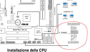
На чтение 10 мин Просмотров 71 Опубликовано 8 апреля 2023 Обновлено 8 апреля 2023
Содержание
- Intel e210882 подключение передней панели
- Шаг 1 — находим шлейфы, идущие от передней панели к мат. плате
- Шаг 2 — находим контакты на материнской плате для подключения передней панели
- Шаг 3 — Подключаем фишки разъемов передней панели к соответствующим разъемам материнской платы
- Вариант первый
- Вариант второй
- eatx12v что это на материнской плате?
- Нет звука через HDMI: устройство уже используется другим приложением
- CLRTC на материнской плате asus что это?
- 3 Комментариев
- Александр
- Куда подключать коннекторы?
- Как правильно подключить коннекторы передней панели?
- Правила подключения коннекторов:
- Но у меня все не так, и вообще нет подписей! Что мне делать??
- Как подключить переднюю панель, если совсем ничего непонятно
- Решение номер раз:
- Решение номер два:
Большинство неопытных компьютерных пользователей считают, что подключить переднюю панель корпуса компьютера, на которой находятся кнопки включения и перезагрузки компьютера, а также USB входы и аудио выходы, к материнской плате является сложным и трудно выполнимым занятием.
Но, как часто это бывает, потратив 5 минут на изучение вопроса, все становится понятно и очень даже выполнимо. В данной статье мы рассмотрим последовательность действий, которые необходимо выполнить для успешного и правильного подключения передней панели к к материнской плате, будь это плата фирмы Asus, Gigabyte, Asrock, MSI и других.
Шаг 1 — находим шлейфы, идущие от передней панели к мат. плате
Это те самые шлейфы, которые мы будем подключать к соответствующим разъемам материнской платы. Особенность этих самых шлейфов, по которым их можно найти среди других проводов в корпусе системного блока это надписи на концах их разъемов:
- Power SW (PWRBTN) — Кнопка включения компьютера;
- Reset SW (Reset) — Кнопка перезагрузки;
- HDD LED ( >

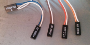
Разъемы передней панели системного блока
Для тех, у кого Power LED состоит из 2-ух фишек на 2 и 3 контакта (как на рисунке выше) обоснование следующее: на некоторых материнских платах разъем подключения POWER LED (индикатор включения компьютера) выполнен на 3-ех контактах (средний не используется), а на некоторых на 2-ух. Поэтому в вашем случае нужно использовать либо одну фишку Power Led, либо другую.
Шаг 2 — находим контакты на материнской плате для подключения передней панели
Стоит отметить, что подключение кнопок включения, перезагрузки, индикатора работы жесткого диска и индикатора включения компьютера, а также спикера (F_Panel) это одна группа разъемов (1 на рисунке ниже), подключение передних USB (USB) — другая группа (2 на рисунке ниже) и разъемы наушников с микрофоном (AAFP) — третья (3 на рисунке ниже).
На материнской плате они расположены примерно вот так:
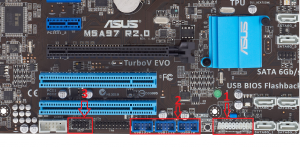
Расположение разъемов на материнской плате для подключения передней панели системного блока
Шаг 3 — Подключаем фишки разъемов передней панели к соответствующим разъемам материнской платы
Далее возможны 2 варианта развития ситуации.
Вариант первый
На вашей материнской плате все контакты подписаны и вы просто одеваете фишки на контакты соблюдая соответствующие названия и полярность. Полярность важна для HDD LED (IDE LED) и Power LED. На плате плюсовой контакт подписан как «+», а на фишке плюсовой контакт это цветной провод (отличный от белого и черного). Либо же если все провода от передней панели черного цвета, то на них «+» тоже будет подписан.
Полярность + и — при подключении PLED и HDLED
Даже если вы перепутаете полярность, то ничего страшного не произойдет. Просто на просто при включении не будет загораться кнопка включения и не будет моргать светодиод активности жесткого диска. В этом случае просто переверните не работающую фишку вверх ногами на контактах мат. платы, чтобы поменять полярность.
Вариант второй
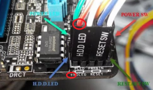
Контакты на материнской плате не подписаны, как на фото ниже.
Контакты подключения передней панели на материнской плате без подписей
В этом случае вам нужно определить модель своей материнской платы, найти ее в интернете и посмотреть документацию по распиновке контактов кнопок, индикаторов, usb и звуковым выходам.
Инструкция со схемой подключения передней панели к материнской плате
Подключение передних аудио выходов и микрофона
особенности соблюдения полярности при подключении передней папнели
Подключение передних USB входов к материнской плате
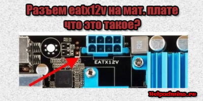
eatx12v что это на материнской плате?
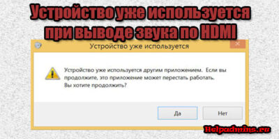
Нет звука через HDMI: устройство уже используется другим приложением
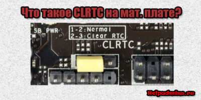
CLRTC на материнской плате asus что это?
3 Комментариев
Александр
Сайт датирован 2018 годом, а фрагменты мам c разъёмами и др.элементами 10-летней давности ;-(
Автор статьи: Шилин Алексей
Всем привет! В этой статье я наглядно покажу как правильно подключать кнопки (POWER, RESET) и устройства передней панели (F_PANEL, F_AUDIO и F_USB). Дело не хитрое, но стоит Вашего внимания.
В начале пару советов:
Разберу наглядно данное дело на старенькой материнской плате от фирмы Gigabyte модель GA-945GCM-S2C. Сразу скажу — Схемы подключения рисовал исключительно для данной статьи и на конкретном примере, цвета проводов у Вас будут отличаться. Главное понять и смысл подключения и воплотить (проверить) на своём ПК.

На этой картинке отображены разъёмы материнской платы для подключения коннекторов.
В основном (бывают исключения) под разъёмами мелким шрифтом написаны порядок подключения коннекторов и полярность. В моём случае указано:
PWR_LED (три разъемчика) — индикация включенного компьютера;
+PW- (PWRSW) — кнопка включения питания ПК;
-RES+ (RESET) — кнопка для перезагрузки ПК;
+HD- (IDE_LED, HDD_LED) — светодиод обращения к жесткому диску;
+SPEAK- (SPEAKER) — тот самый сигнал(ы), который издаёт компьютер при включении, если обнаружена ошибка.
Коннекторы выглядят так (см. скрины)

К каждому коннектрору подходят два провода:
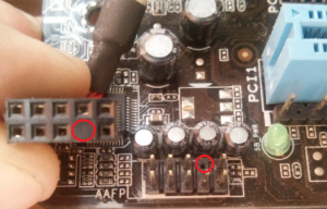
В данном случае белые это минус «-» или Ground (земля) , а цветные «+». У коннектора SPEAKER (черный, красный) — чёрный «+», а красный «-«. Чтобы определить полярность коннекторов, достаточно его перевернуть на тыльную сторону — видим на против одного проводка маленький чёрный треугольник — это «+».
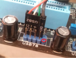
Переходим к следующему этапу, подключение передних дополнительных USB — разъёмов и картридера в разъёмы F_USB2 и F_USB1 (разницы нет, но лучше начинать по порядку). Если уже коннектор «спаянный», т.е. все проводки собраны в одну колодку — процесс значительно упрощается.
Просто подключаем этот «большой» коннектор состоящий из: восьми проводков, одного пустого и одного запаянного разъёма (всего десять) таким образом, чтобы ПУСТОЙ разъемчик совпал с ЗАПАЯННЫМ гнездом в коннекторе. (см. скрины)

А, вот если у Вас пучок проводов как на картинке — нарисую наглядную схемку:)

Здесь мы видим: POWER (Питание — 2 шт.), GND (Ground — «земля» 2шт.), D3+ (плюс), D3- (минус) на один порт usb и D2+ (плюс), D2- (минус) на другой порт. Как Вы уже догадались, два коннектора POWER идентичны и их можно менять местами между собой, так же как и GND. Главное не перепутать местами POWER и GND.

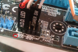
Так теперь осталось разобраться с подключением F_AUDIO разъемов для микрофона и наушников.
Опять же, если Вам повезло и от передней панели идёт большая колодка с 10-ью гнездами, просто вставляем (тут точно не ошибетесь). У меня случай поинтереснее. ) А, именно такие коннекторы: SPK R (выход правого канала на переднюю панель), SPK L (выход левого канала на переднюю панель), MIC (выход микрофона на переднюю панель) и GND.


Вот и всё подключено. Спасибо за внимание, удачи.
Если у Вас отличаются провода, названия коннекторов (колодок) и тд. и тп. не ленитесь, скачайте с официального сайта производителя Вашей материнской платы мануал (руководство) и там 99% найдёте схемы подключения всех F_PANEL, F_AUDIO и F_USB.
Черный экран windows 7 — Узнайте как избавиться от черного экрана Windows 7.
Восстановление windows 7 — Как произвести восстановление системы Windows 7.
Как активировать windows 7 — Как легально активировать windows 7.
Зачастую человек, впервые (а бывает, что далеко и не в первый раз) собирающий компьютер, сталкивается с тем, что не знает, как правильно да и куда вообще подключать кнопки reset, power, LED-индикаторы, спикер, который издает писк при включении. Я покажу несколько примеров, по которым вы сможете понять принцип, как правильно подключается вообще любая передняя панель, расскажу некоторые секреты, которые использую сам в своей работе.
Ничего сложного в этом нет, если придерживаться простых правил и рекомендаций, о которых сейчас и пойдет речь.
Куда подключать коннекторы?
Этот раздел для тех, кто не в курсе, куда именно подключается передняя панель. Если это не про вас, переходите сразу к следующему разделу и читайте дальше.
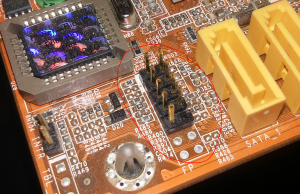
Для начала давайте разберемся, как вообще выглядит то место на материнской плате, куда подключается передняя панель компьютера. Для наглядности просто хочу показать несколько фотографий, по ним вы легко определите, как выглядит этот разъем на материнской плате:
Как видите, они могут слегка отличаться друг от друга. Также хочу обратить внимание, что расположение снизу справа не является обязательным, иногда эти контакты располагаются и по центру снизу материнской платы.
Как правильно подключить коннекторы передней панели?
На большинстве материнских плат уже нанесена разметка, что и куда подключать. Вот самый простой и наглядный пример:

+MSG- (желтый цвет) – подключение индикатора работы компьютера;
+HD- (синий цвет) – подключение индикатора работы жесткого диска (HDD);
+PW- (красный цвет) – подключение кнопки питания (Power);
-RES+ (зеленый цвет) – подключение кнопки сброс (Reset);
+SPEAK- (оранжевый цвет) – подключение спикера (тот, который издает писк при включении);
Цвета здесь ничего не значат, просто производитель решил сделать такую разметку.
Правила подключения коннекторов:
Есть простые общие правила, используя которые, вы правильно и легко подключите коннекторы передней панели к материнской плате:
- Подключение кнопок Power и Reset не имеет полярности, так как эти кнопки попросту работают на замыкание контактов. Несмотря на то, что на плате указаны + и – для этих кнопок, никакого значения они не имеют.
- Важно соблюдать полярность при подключении светодиодов и спикера, иначе работать не будут.
- На материнской плате для каждого типа коннекторов его плюс всегда слева, а минус – справа. Это справедливо для всех материнских плат. Если нет обозначений + и — , используйте это правило.
- На проводах светодиодов – любой цветной провод это плюс, а черный или белый – минус.
Но у меня все не так, и вообще нет подписей! Что мне делать??
Многие контактные площадки на современных ATX-платах имеют такой вид:
В таком случае лучше всего поискать инструкцию к материнской плате и найти там вот такой (или похожий) раздел:
+PWR_LED- – индикатор работы;
+HDD_LED- – индикатор работы жесткого диска;
PWR_SW – кнопка включения (Power);
RESET – кнопка «сброс»;
SPEAKER – спикер (та самая нудная пищащая хрень  )
)
Данная схема подключения передней панели используется для большинства современных ATX-плат.
Как подключить переднюю панель, если совсем ничего непонятно

Вот хороший пример — старый тип распайки, к тому же мой самый не любимый. Во-первых, ничего не подписано, а во-вторых, контакты никак не скомпонованы, и не понятно какие из них образуют пары.
Здесь есть два решения проблемы:
Решение номер раз:
Найти инструкцию к материнской плате и посмотреть, где и какие контакты. Гениально, правда?  Кэп отдыхает
Решение номер два:
Если нет инструкции, то можно воспользоваться следующим способом: компьютер включается в электрическую сеть, а затем по очереди кратковременно замыкаются отверткой рядом стоящие пары контактов. Когда при очередном замыкании компьютер запустится, — та пара контактов и отвечает за кнопку включения (Power). Таким же способом находится кнопка сброс (reset), только уже при работающем компьютере (при замыкании контактов для кнопки Reset компьютер перезагрузится)
Индикаторы работы жесткого диска и работы компьютера придется уже искать методом «втыка», пока они не заработают.
Примечание: таким способом я пользуюсь довольно давно, и ни одной материнской платы еще не испортил. Вам же советую быть крайне аккуратными, — за убитые платы по вашей неосторожности я не отвечаю.
На этом я заканчиваю разбор подключений передней панели. В будущем планируется еще много интересных и полезных статей – подписывайтесь на обновления, чтобы быть в курсе событий на сайте.
Если у вас все еще остались вопросы – задавайте их в комментариях, не стесняйтесь — помогу чем смогу
Источник