
-
Драйверы
17
-
Инструкции по эксплуатации
1

Gigabyte GA-F2A88XM-HD3 инструкция по эксплуатации
(36 страниц)
- Языки:Английский
-
Тип:
PDF -
Размер:
11.51 MB
Просмотр
На NoDevice можно скачать инструкцию по эксплуатации для Gigabyte GA-F2A88XM-HD3. Руководство пользователя необходимо для ознакомления с правилами установки и эксплуатации Gigabyte GA-F2A88XM-HD3. Инструкции по использованию помогут правильно настроить Gigabyte GA-F2A88XM-HD3, исправить ошибки и выявить неполадки.
![]()
GA-F2A88XM-HD3
User’s Manual
Rev. 3001
12ME-F288HD3-3001R
Motherboard
GA-F2A88XM-HD3
Aug. 23, 2013
Motherboard
GA-F2A88XM-HD3
Aug. 23, 2013
Copyright
© 2013 GIGA-BYTE TECHNOLOGY CO., LTD. All rights reserved.
The trademarks mentioned in this manual are legally registered to their respective owners.
Disclaimer
Information in this manual is protected by copyright laws and is the property of GIGABYTE.
ChangestothespecificationsandfeaturesinthismanualmaybemadebyGIGABYTEwithoutpriornotice.
No part of this manual may be reproduced, copied, translated, transmitted, or published in any form or by any means without GIGABYTE’s prior written permission.
In order to assist in the use of this product, carefully read the User’s Manual.
For product-related information, check on our website at: http://www.gigabyte.com
Identifying Your Motherboard Revision
The revision number on your motherboard looks like this: «REV: X.X.» For example, «REV: 1.0» means the revision of the motherboard is 1.0. Check your motherboard revision before updating motherboard BIOS, drivers, or when looking for technical information.
Example:

Table of Contents
|
GA-F2A88XM-HD3 Motherboard Layout……………………………………………………………… |
4 |
|
|
GA-F2A88XM-HD3 Motherboard Block Diagram………………………………………………….. |
5 |
|
|
Chapter 1 Hardware Installation………………………………………………………………………….. |
6 |
|
|
1-1 |
Installation Precautions………………………………………………………………………… |
6 |
|
1-2 |
Product Specifications…………………………………………………………………………. |
7 |
|
1-3 |
Installing the APU………………………………………………………………………………… |
9 |
|
1-4 |
Installing the Memory…………………………………………………………………………. |
10 |
|
1-5 |
Installing an Expansion Card………………………………………………………………. |
10 |
|
1-6 |
Setup of the AMD Dual Graphics Configuration…………………………………….. |
10 |
|
1-7 |
Back Panel Connectors……………………………………………………………………….. |
11 |
|
1-8 |
Internal Connectors……………………………………………………………………………. |
13 |
|
Chapter 2 BIOS Setup……………………………………………………………………………………… |
19 |
|
|
2-1 |
Startup Screen………………………………………………………………………………….. |
19 |
|
2-2 |
M.I.T…………………………………………………………………………………………………. |
20 |
|
2-3 |
System Information……………………………………………………………………………. |
23 |
|
2-4 |
BIOS Features…………………………………………………………………………………… |
24 |
|
2-5 |
Peripherals……………………………………………………………………………………….. |
26 |
|
2-6 |
Power Management…………………………………………………………………………… |
28 |
|
2-7 |
Save & Exit……………………………………………………………………………………….. |
30 |
|
Chapter 3 Appendix…………………………………………………………………………………………. |
31 |
|
|
3-1 Configuring SATA Hard Drive(s)…………………………………………………………… |
31 |
|
|
3-2 |
Drivers Installation……………………………………………………………………………… |
34 |
|
Regulatory Statements…………………………………………………………………………………. |
35 |
|
|
Contact Us………………………………………………………………………………………………….. |
36 |
— 3 —

GA-F2A88XM-HD3 Motherboard Layout
KB_MS_USB
VGA
ATX_12V
Socket FM2+
ATX
DVI
USB_HDMI
USB30_LAN CI
AUDIO
Realtek®
GbE LAN
CPU_FAN
SYS_FAN
BAT
PCIEX16 GA-F2A88XM-HD3
PCIEX1
iTE® Super I/O
PCI
CODEC PCIEX4 SPDIF_O
|
F_AUDIO COM |
LPT |
M_BIOS
B_BIOS
 CLR_CMOS
|
SATA3 |
4 5 |
|
AMD A88X |
|
|
SATA3 |
2 3 |
|
SATA3 1 |
|
|
SATA3 0 |
F_USB2 F_USB1 F_PANEL F_USB30
Box Contents
|
55 |
GA-F2A88XM-HD3 motherboard |
||
|
55 |
Motherboard driver disk |
55 |
Two SATA cables |
|
55 |
User’s Manual |
55 |
I/O Shield |
The box contents above are for reference only and the actual items shall depend on the product package you obtain. The box contents are subject to change without notice.
— 4 —
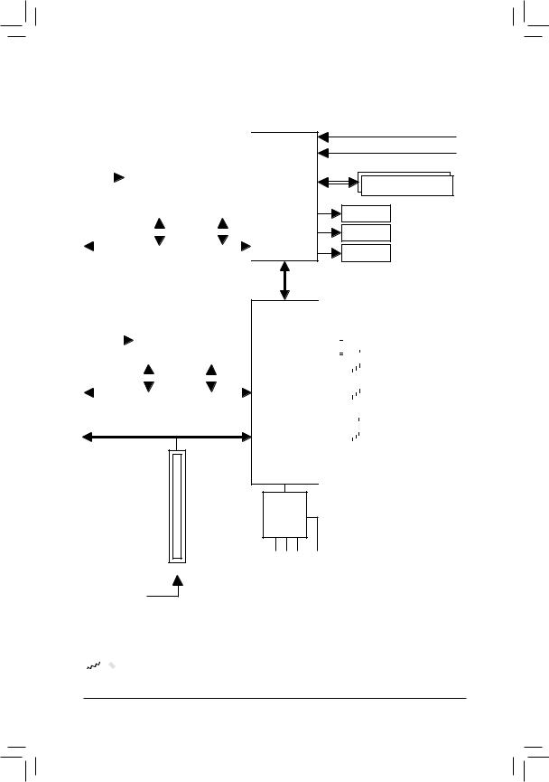
GA-F2A88XM-HD3 Motherboard Block Diagram
|
1 PCI Express x16 |
|||||||||||||||||||||
|
1 PCI Express x4 |
|||||||||||||||||||||
|
PCIe CLK |
|||||||||||||||||||||
|
(100 MHz) |
|||||||||||||||||||||
|
x4 |
x16 |
||||||||||||||||||||
|
PCI Express Bus |
|||||||||||||||||||||
|
LAN |
|||||||||||||||||||||
|
1 PCI Express x1 |
|||||||||||||||||||||
|
RJ45 |
|||||||||||||||||||||
|
PCIe CLK |
Realtek® |
||||||||||||||||||||
|
GbE LAN |
|||||||||||||||||||||
|
(100 MHz) |
|||||||||||||||||||||
|
x1 |
x1 |
||||||||||||||||||||
|
PCI Express Bus |
PCI Bus
AMD APU
UMI
AMD A88X
CODEC
APU CLK+/- (100 MHz)
DISP CLK+/- (100 MHz)
DDR3 2133/1866/1600/1333 MHz
Dual Channel Memory
HDMI
DVI-D
D-Sub
|
Dual BIOS |
||||||||||||||
|
8 SATA 6Gb/s |
||||||||||||||
|
4 USB 3.0/2.0 |
||||||||||||||
|
8 USB 2.0/1.1 |
||||||||||||||
|
LPC |
iTE® |
COM |
||||||||||||
|
Bus |
||||||||||||||
|
LPT |
||||||||||||||
|
Super I/O |
||||||||||||||
|
PS/2 KB/Mouse |
|
(Center/Subwoofer |
(Front |
S/PDIFOut |
|
Out)Speaker |
Out)Speaker Out)Speaker |
|
|
MIC |
(Rear |
|
|
Line |
||
|
In |
||
|
Out |
||
|
Line |

 For detailed product information/limitation(s), refer to «1-2 Product Specifications.»
— 5 —

Chapter 1 Hardware Installation
1-1 Installation Precautions
The motherboard contains numerous delicate electronic circuits and components which can become damaged as a result of electrostatic discharge (ESD). Prior to installation, carefully read the user’s manual and follow these procedures:
•• Prior to installation, make sure the chassis is suitable for the motherboard.
•• Prior to installation, do not remove or break motherboard S/N (Serial Number) sticker or warranty sticker provided by your dealer. These stickers are required for warranty validation.
•• Always remove the AC power by unplugging the power cord from the power outlet before installing or removing the motherboard or other hardware components.
•• When connecting hardware components to the internal connectors on the motherboard, make sure they are connected tightly and securely.
•• When handling the motherboard, avoid touching any metal leads or connectors.
•• It is best to wear an electrostatic discharge (ESD) wrist strap when handling electronic components such as a motherboard, CPU or memory. If you do not have an ESD wrist strap, keep your hands dry and first touch a metal object to eliminate static electricity.
•• Prior to installing the motherboard, please have it on top of an antistatic pad or within an electrostatic shielding container.
•• Before unplugging the power supply cable from the motherboard, make sure the power supply has been turned off.
•• Before turning on the power, make sure the power supply voltage has been set according to the local voltage standard.
•• Before using the product, please verify that all cables and power connectors of your hardware components are connected.
•• To prevent damage to the motherboard, do not allow screws to come in contact with the motherboard circuit or its components.
•• Make sure there are no leftover screws or metal components placed on the motherboard or within the computer casing.
•• Do not place the computer system on an uneven surface.
•• Do not place the computer system in a high-temperature environment.
•• Turning on the computer power during the installation process can lead to damage to system components as well as physical harm to the user.
•• If you are uncertain about any installation steps or have a problem related to the use of the product, please consult a certified computer technician.
— 6 —
1-2 Product Specifications
|
APU |
FM2+ Socket: |
||
|
— |
AMD A series processors |
||
|
— |
AMD Athlon™ series processors |
||
|
(Go to GIGABYTE’s website for the latest CPU support list.) |
|||
|
Chipset |
AMD A88X |
|
Memory |
2 x 1.5V DDR3 DIMM sockets supporting up to 64 GB of system memory |
|
|
* Due to a Windows 32-bit operating system limitation, when more than 4 GB of physical |
||
|
memory is installed, the actual memory size displayed will be less than the size of |
||
|
the physical memory installed. |
||
|
* The maximum 64 GB of system memory can be supported using 16 GB (or above) |
||
|
memory modules. GIGABYTE will update the memory support list on the official |
||
|
website when the memory modules are available on the market. |
||
|
Dual channel memory architecture |
||
|
Support for DDR3 2133/1866/1600/1333 MHz memory modules |
||
|
Support for AMD Memory Profile (AMP)/Extreme Memory Profile (XMP) memory |
||
|
modules |
||
|
(Go to GIGABYTE’s website for the latest supported memory speeds and memory |
||
|
modules.) |
||
|
Onboard |
APU with integrated AMD Radeon™ HD 8000/7000 series graphics: |
|
|
Graphics |
* To use the onboard graphics ports, you must install an AMD APU with integrated |
|
|
graphics. |
||
|
— |
1 x D-Sub port, supporting a maximum resolution of 1920×1200 |
|
|
— |
1 x DVI-D port, supporting a maximum resolution of 2560×1600 |
|
|
* Support for 2560×1600 resolution requires both a monitor and cable that support |
||
|
Dual Link DVI. |
||
|
* The DVI-D port does not support D-Sub connection by adapter. |
||
|
— |
1 x HDMI port, supporting a maximum resolution of 4096×2160 |
|
|
* The resolution of 4096×2160 can be supported when using an FM2+ APU; the |
||
|
maximum resolution supported is 1920×1200 when using an FM2 APU. |
||
|
* Support for HDMI 1.4a version. |
||
|
— |
Maximum shared memory of 2 GB |
|
Audio |
Realtek® ALC887 codec |
|
|
High Definition Audio |
||
|
2/4/5.1/7.1-channel |
||
|
* To configure 7.1-channel audio, you have to use an HD front panel audio module |
||
|
and enable the multi-channel audio feature through the audio driver. |
||
|
Support for S/PDIF Out |
||
|
LAN |
Realtek® GbE LAN chip (10/100/1000 Mbit) |
|
|
Expansion Slots |
1 x PCI Express x16 slot, running at x16 (PCIEX16) |
|
|
* For optimum performance, if only one PCI Express graphics card is to be installed, |
||
|
be sure to install it in the PCIEX16 slot. |
(The PCIEX16 slot conforms to PCI Express 3.0 standard.)
*To support PCI Express 3.0, you must install an FM2+ APU.
1 x PCI Express x16 slot, running at x4 (PCIEX4)
1 x PCI Express x1 slot
(The PCIEX4 and PCI Express x1 slots conform to PCI Express 2.0 standard.)
1 x PCI slot
|
Multi-Graphics |
Support for AMD Dual Graphics technology |
|
|
Technology |
* Only A series APUs support AMD Dual Graphics. |
|
|
— 7 — |
Storage Interface Chipset:
8 x SATA 6Gb/s connectors
—Support for RAID 0, RAID 1, RAID 5, RAID 10, and JBOD
|
USB |
Chipset: |
|
|
— |
4 USB 3.0/2.0 ports (2 ports on the back panel, 2 ports available through the |
|
|
internal USB header) |
||
|
— |
8 USB 2.0/1.1 ports (4 ports on the back panel, 4 ports available through the |
|
|
internal USB headers) |
||
|
Internal |
1 x 24-pin ATX main power connector |
|
|
Connectors |
1 x 8-pin ATX 12V power connector |
8 x SATA 6Gb/s connectors
1 x APU fan header
1 x system fan header
1 x front panel header
1 x front panel audio header
1 x S/PDIF Out header
1 x USB 3.0/2.0 header
2 x USB 2.0/1.1 headers
1 x serial port header
1 x parallel port header
1 x chassis intrusion header
1 x Clear CMOS jumper
|
Back Panel |
1 x PS/2 keyboard/mouse port |
|
Connectors |
1 x D-Sub port |
|
1 x DVI-D port |
|
|
1 x HDMI port |
|
|
2 x USB 3.0/2.0 ports |
|
|
4 x USB 2.0/1.1 ports |
|
|
1 x RJ-45 port |
|
|
3 x audio jacks (Line In, Line Out, Mic In) |
|
I/O Controller |
iTE® I/O Controller Chip |
|
|
Hardware |
System voltage detection |
|
|
Monitor |
APU/System temperature detection |
APU/System fan speed detectionAPU/System fan speed control
* Whether the fan speed control function is supported will depend on the cooler you install.
|
BIOS |
2 x 64 Mbit flash |
|
|
Use of licensed AMI EFI BIOS |
Support for DualBIOS™
PnP 1.0a, DMI 2.0, SM BIOS 2.6, ACPI 2.0a
— 8 —

|
Unique Features |
Support for @BIOS |
||
|
Support for Q-Flash |
|||
|
Support for Xpress Install |
|||
|
Support for EasyTune |
|||
|
* Available functions in EasyTune may differ by motherboard model. |
|||
|
Support for Smart Recovery 2 |
|||
|
Support for ON/OFF Charge |
|||
|
Bundled |
Norton® Internet Security (OEM version) |
||
|
Software |
|||
|
Operating |
Support for Windows 8.1/8/7 32-bit/64-bit |
||
|
System |
* If you plan to install Windows 8.1, please download the latest drivers from GIGABYTE’s |
||
|
website. |
Support for Windows XP-32bit
*To support Windows XP 32-bit, you must install an AMD FM2 Trinity APU.
|
Form Factor |
Micro ATX Form Factor; 24.4cm x 17.4cm |
*GIGABYTE reserves the right to make any changes to the product specifications and product-related information without prior notice.
*Please visit the Support & Downloads\Utility page on GIGABYTE’s website to check the supported operating system(s) for the software listed in the «Unique Features» and «Bundled Software» columns.
1-3 Installing the APU
Read the following guidelines before you begin to install the APU:
•• Make sure that the motherboard supports the APU.
(Go to GIGABYTE’s website for the latest APU support list.)
•• Always turn off the computer and unplug the power cord from the power outlet before installing the APU to prevent hardware damage.
•• Locate the pin one of the APU. The APU cannot be inserted if oriented incorrectly.
•• Apply an even and thin layer of thermal grease on the surface of the APU.
•• Do not turn on the computer if the APU cooler is not installed, otherwise overheating and damage of the APU may occur.
•• Set the APU host frequency in accordance with the APU specifications. It is not recommended that the system bus frequency be set beyond hardware specifications since it does not meet the standard requirements for the peripherals. If you wish to set the frequency beyond the standard specifications, please do so according to your hardware specifications including theAPU, graphics card, memory, hard drive, etc.
Installing the APU
Locate the pin one (denoted by a small triangle) of the APU socket and the APU.
|
A Small Triangle Mark- |
FM2+ Socket |
A Small Triangle |
APU |
|
|
ing Denotes Pin One |
Marking Denotes |
|||
|
of the Socket |
APU Pin One |
— 9 —
1-4 Installing the Memory
Read the following guidelines before you begin to install the memory:
•• Make sure that the motherboard supports the memory. It is recommended that memory of the same capacity, brand, speed, and chips be used.
(Go to GIGABYTE’s website for the latest supported memory speeds and memory modules.)
•• Always turn off the computer and unplug the power cord from the power outlet before installing the memory to prevent hardware damage.
•• Memory modules have a foolproof design. A memory module can be installed in only one direction. If you are unable to insert the memory, switch the direction.
Dual Channel Memory Configuration
This motherboard provides two DDR3 memory sockets and supports Dual Channel Technology. After the memory is installed, the BIOS will automatically detect the specifications and capacity of the memory. Enabling Dual
Channel memory mode will double the original memory bandwidth.
The two DDR3 memory sockets are divided into two channels and each channel has one memory socket as following:
Channel A: DDR3_2Channel B: DDR3_1
Due to APU limitations, read the following guidelines before installing the memory in Dual Channel mode.
1.Dual Channel mode cannot be enabled if only one DDR3 memory module is installed.
2.When enabling Dual Channel mode with two memory modules, it is recommended that memory of the same capacity, brand, speed, and chips be used for optimum performance.
1-5 Installing an Expansion Card
Read the following guidelines before you begin to install an expansion card:
•• Make sure the motherboard supports the expansion card. Carefully read the manual that came with your expansion card.
•• Always turn off the computer and unplug the power cord from the power outlet before installing an expansion card to prevent hardware damage.
1-6 Setup of the AMD Dual Graphics Configuration
A.System Requirements
— AMD A series processor
— Windows 8/7 operating system
— An AMD Dual Graphics technology-supported motherboard (with the BIOS updated to the latest version) and correct driver (make sure the onboard graphics driver version is Rev. 8.982 or above)
— An AMD Radeon™ HD 6000 series graphics card that supports AMD Dual Graphics technology (for more details, please visit AMD’s official website) and correct driver
B.Installing the Graphics Cards and Configuring BIOS Setup
Step 1:
Observe the steps in «1-5 Installing an Expansion Card» and install an AMD Dual Graphics technology-supported graphics card on the PCIEX16 slot. Plug the monitor cable into the graphics card and start up your computer. Step 2:
Enter BIOS Setup to set the following items under the Peripherals\GFX Configuration menu:
— Set Integrated Graphics to Force.
— Set UMA Frame Buffer Size to 512M or above.
Save the settings and exit BIOS Setup. Restart your computer. — 10 —
![]()
C. Configuring the Graphics Card Driver
After installing the graphics card driver in the operating system, go to the AMDVISIONEngineControlCenter. Browse to Performance\AMD Radeon™ Dual Graphics and ensure the Enable AMD Radeon Dual Graphics check box is selected.
(Note) Make sure the drivers for the Chipset, onboard graphics, and external graphics card are properly installed.
1-7 Back Panel Connectors
USB 2.0/1.1 Port
The USB port supports the USB 2.0/1.1 specification. Use this port for USB devices such as a USB keyboard/mouse, USB printer, USB flash drive and etc.
PS/2 Keyboard/Mouse Port
Use this port to connect a PS/2 mouse or keyboard.
D-Sub Port
The D-Sub port supports a 15-pin D-Sub connector and supports a maximum resolution of 1920×1200
(the actual resolutions supported depend on the monitor being used).
Connect a monitor that supports D-Sub connection to this port.
DVI-D Port (Note 1)
The DVI-D port conforms to the DVI-D specification and supports a maximum resolution of 2560×1600.
Connect a monitor that supports DVI-D connection to this port. Please note that the actual resolutions supported are dependent on the monitor being used and support for 2560×1600 resolution requires both a monitor and cable that support Dual Link DVI.
HDMI Port
 The HDMI port is HDCP compliant and supports Dolby True HD and DTS HD


 MasterAudioformats.Italsosupportsupto192KHz/24bit8-channelLPCMaudio output. You can use this port to connect your HDMI-supported monitor. The maximum supported resolution is 4096×2160 (Note 2), but the actual resolutions supported are dependent on the monitor being used.

 After installing the HDMI device, make sure to set the default sound playback device to HDMI.
A. Triple Display Configurations:
Triple-display configurations are supported after you install motherboard drivers in OS. Only dual-display configurations are supported during the BIOS Setup or POST process.
(Note 1) The DVI-D port does not support D-Sub connection by adapter.
(Note 2) The resolution of 4096×2160 can be supported when using an FM2+ APU; the maximum resolution supported is 1920×1200 when using an FM2 APU.
— 11 —
 Loading…
More products and manuals for Motherboards Gigabyte
| Models | Document Type |
|---|---|
|
8S651M-RZ |
User Manual
40 pages |
|
GA-G41MT-S2P |
User Manual
40 pages |
|
GA-H61M-S2H |
User Manual
44 pages |
|
GA-H61M-S2P-B3 |
User Manual
40 pages |
|
GA-A75M-D2H |
User Manual
96 pages |
|
GA-A55M-DS2 |
User Manual
44 pages |
|
GA-990XA-UD3 |
User Manual
100 pages |
|
GA-J1800N-D2H (rev. 1.0) |
User Manual
32 pages |
|
GA-F2A88X-UP4 (rev. 3.0) |
User Manual
96 pages |
|
GA-Z97X-SOC FORCE |
User Manual
124 pages |
|
GA-F2A78M-D3H (rev. 3.0) |
User Manual
96 pages |
|
GA-Z77-HD4 |
User Manual
104 pages |
|
GA-A75M-S2V |
User Manual
44 pages |
|
GA-H97-D3H |
User Manual
80 pages |
|
GA-78LMT-S2P |
User Manual
44 pages |
|
GA-H61M-USB3H |
User Manual
32 pages |
|
8VM533M-RZ |
User Manual
36 pages |
|
GA-P55M-UD2 |
User Manual
120 pages |
|
GA-EG45M-UD2H (rev. 1.0) |
User Manual
112 pages |
|
Motherboard GA-Z68A-D3-B3 Intel Z68 LGA1155 PCI Express DDR3 |
Manual
3 pages |

-
Gigabyte GA-F2A88XM-HD3 — page 1
GA-F2A88XM-HD3 User’s Manual Rev . 30 01 1 2ME -F288HD3-300 1R …
-
Gigabyte GA-F2A88XM-HD3 — page 2
Motherboard GA-F2A88XM-HD3 Aug. 23, 2013 Aug. 23, 2013 Motherboard GA-F2A88XM-HD3 Copyright © 2013 GIGA-BYTE TECHNOLOGY CO., L TD. All rights reserved. The trademarks mentioned in this manual are legally registered to their respective owners. Disclaimer Information in this manual is protected by copyright laws and is the property of GIGABYTE. Chan …
-
Gigabyte GA-F2A88XM-HD3 — page 3
— 3 — T able of Contents GA -F2 A88XM — HD3 Mot herboard L ay out ……………………………………………………………… 4 GA -F2 A88XM — HD3 Mot herboard B lock Diagr am ………………………………………………….. 5 Chapter 1 Hardware Inst allation ………………………………………………………… …
-
Gigabyte GA-F2A88XM-HD3 — page 4
— 4 — GA-F2A88XM- HD3 Mo therboard Lay out The box contents above are for reference only and the actual items shall depend on the product package you obtain. The box contents are subject to change without notice. Box Contents 5 GA-F2A88XM-HD3 motherboard 5 Motherboard driver disk 5 T wo SA T A cables 5 User’s Manual 5 I/O Shield KB_MS_USB AUDI …
-
Gigabyte GA-F2A88XM-HD3 — page 5
— 5 — For detailed product information/limitation(s), refer to «1-2 Product Specications.» GA- F2A88 XM — HD 3 Mot herboard Block Diagram UMI PCI Bus 1 PCI PCI CLK (33 MHz) COM LPC Bus PS/2 KB/Mouse Dual BIOS 8 USB 2.0/1.1 8 SA T A 6Gb/s PCI Express Bus PCI Express Bus PCIe CLK (100 MHz) PCIe CLK (100 MHz) 1 PCI Express x1 x1 x1 LAN RJ …
-
Gigabyte GA-F2A88XM-HD3 — page 6
— 6 — Chapter 1 Hardware Installation 1- 1 Installation Precautions The motherboard contains numerous delicate electronic circuits and components which can become damaged as a result of electrostatic discharge (ESD). Prior to installation, carefully read the user’s manual and follow these procedures: • Prior to installation, make sure the ch …
-
Gigabyte GA-F2A88XM-HD3 — page 7
— 7 — 1- 2 P roductSpe cications APU FM2+ Socket: — AMD A series processors — AMD Athlon ™ series processors ( Go to GIGABYTE’s website for the latest CPU support list. ) Chipset AMD A88X Memory 2 x 1.5V DDR3 DIMM sockets supporting up to 64 GB of system memory * Due to a Windows 32-bit operating system limitation , when …
-
Gigabyte GA-F2A88XM-HD3 — page 8
— 8 — Storage Interface Chipset: 8 x SA T A 6Gb/s connectors — Support for RAID 0, RAID 1, RAID 5, RAID 10, and JBOD USB Chipset: — 4 USB 3.0/2.0 ports ( 2 ports on the back panel, 2 ports available through the internal USB header ) — 8 USB 2.0/1.1 ports ( 4 ports on the back panel, 4 ports available through the internal USB headers ) Inter …
-
Gigabyte GA-F2A88XM-HD3 — page 9
— 9 — 1-3 Installing the APU Read the following guidelines before you begin to install the APU: • Make sure that the motherboard supports the APU. (Go to GIGABYTE’s website for the latest APU support list.) • Always turn off the computer and unplug the power cord from the power outlet before installing the APU to prevent hardware damage. ? …
-
Gigabyte GA-F2A88XM-HD3 — page 10
— 10 — 1- 4 Installing the Memor y DualChannelMemoryConguration This motherboard provides two DDR3 memory sockets and supports Dual Channel T echnology. After the memory is installed, the BIOS will automatically detect the specications and capacity of the memory . Enabling Dual Channel memory mode will double the original memory band …
-
Gigabyte GA-F2A88XM-HD3 — page 11
— 1 1 — 1- 7 Back Panel Con nec tors USB 2.0/1.1 Port The USB port supports the USB 2.0/1.1 specication. Use this port for USB devices such as a USB keyboard/mouse, USB printer , USB ash drive and etc. PS/2 Keyboard/Mouse Port Use this port to connect a PS/2 mouse or keyboard. D-Sub Port The D-Sub port supports a 15-pin D-Sub connector and su …
-
Gigabyte GA-F2A88XM-HD3 — page 12
— 12 — RJ-45 LAN Port The Gigabit Ethernet LAN port provides Internet connection at up to 1 Gbps data rate. The following describes the states of the LAN port LEDs. USB 3.0/2.0 Port The USB 3.0 port supports the USB 3.0 specication and is compatible to the USB 2.0/1.1 specication. Use this port for USB devices such as a USB keyboard/mouse, US …
-
Gigabyte GA-F2A88XM-HD3 — page 13
— 13 — 1-8 Internal Connec tors Read the following guidelines before connecting external devices: • First make sure your devices are compliant with the connectors you wish to connect. • Before installing the devices, be sure to turn off the devices and your computer . Unplug the power cord from the power outlet to prevent damage to the devices. …
-
Gigabyte GA-F2A88XM-HD3 — page 14
— 14 — 1/2) A TX_12V/A TX (2×4 12V Power Connector and 2×12 Main Power Connector) With the use of the power connector , the power supply can supply enough stable power to all the components on the motherboard. Before connecting the power connector , rst make sure the power supply is turned off and all devices are properly installed. The power co …
-
Gigabyte GA-F2A88XM-HD3 — page 15
— 15 — 5) SA T A3 0/1/2/3/4/5/6/7 (SA T A 6Gb/s Connectors) The SA T A connectors conform to SA T A 6Gb/s standard and are compatible with SA T A 3Gb/s and SA T A 1.5Gb/s standard. Each SA T A connector supports a single SA T A device. The AMD A88X Chipset supports RAID 0, RAID 1, RAID 5, RAID 10, and JBOD. Refer to Chapter 3, «Conguring SA …
-
Gigabyte GA-F2A88XM-HD3 — page 16
— 16 — 7) F_AUDIO(FrontPanel AudioHeader) The front panel audio header supports Intel High Denition audio (HD) and AC’97 audio. Y ou may connect your chassis front panel audio module to this header . Make sure the wire assignments of the module con — nector match the pin assignments of the motherboard header . Incorrect conne …
-
Gigabyte GA-F2A88XM-HD3 — page 17
— 17 — 10) F_USB1/F_USB2 (USB 2.0/1.1 Headers) The headers conform to USB 2.0/1.1 specication. Each USB header can provide two USB ports via an optional USB bracket. For purchasing the optional USB bracket, please contact the local dealer . Pin No. Denition Pin No. Denition 1 Power (5V) 6 USB DY+ 2 Power (5V) 7 GND 3 USB DX- 8 GND 4 USB DY …
-
Gigabyte GA-F2A88XM-HD3 — page 18
— 18 — 15) CLR_CMOS(ClearCMOSJumper) Use this jumper to clear the BIOS conguration and reset the CMOS values to factory defaults. T o clear the CMOS values, use a metal object like a screwdriver to touch the two pins for a few seconds. • Always turn off your computer before clearing the CMOS values. • After system restart, go to …
-
Gigabyte GA-F2A88XM-HD3 — page 19
— 19 — Chapter2 BIOSSetup • Because BIOS ashing is potentially risky, if you do not encounter problems using the current version of BIOS, it is recommended that you not ash the BIOS. T o ash the BIOS, do it with caution. Inadequate BIOS ashing may result in system malfunction. • It is recommended that you not alter the defa …
-
Gigabyte GA-F2A88XM-HD3 — page 20
— 20 — 2- 2 M.I. T . Whether the system will work stably with the overclock/overvoltage settings you made is dependent on your overall system congurations. Incorrectly doing overclock/overvoltage may result in damage to CPU, chipset, or memory and reduce the useful life of these components. This page is for advanced users only and we recommend y …
-
Gigabyte GA-F2A88XM-HD3 — page 21
— 21 — & ExtremeMemoryProle(X.M.P .) (Note 2) Allows the BIOS to read the SPD data on XMP memory module(s) to enhance memory performance when enabled. Disabled Disables this function. (Default) Prole1 Uses Prole 1 settings. Prole2 (Note 2) Uses Prole 2 settings. & AMD MemoryProle(A.M.P .) ( …
-
Gigabyte GA-F2A88XM-HD3 — page 22
— 22 — ` Channel A/B Timing Settings This sub-menu provides memory timing settings for each channel of memory . The respective timing setting screens are congurable only when DRAM Timing Selectable is set to Quick or Expert . Note: Y our system may become unstable or fail to boot after you make changes on the memory timings. If this occurs, plea …
-
Gigabyte GA-F2A88XM-HD3 — page 23
— 23 — & Slope PWM Allows you to control the fan speed. This item is congurable only when CPU Fan Speed Control is set to Manual . Options are: 0.75 PWM value / o C ~ 2.50 PWM value / o C. & System Fan Speed Control (SYS_F AN Connector) Allows you to determine whether to enable the fan speed control function and adjust the fan speed. …
-
Gigabyte GA-F2A88XM-HD3 — page 24
— 24 — & Access Level Displays the current access level depending on the type of password protection used. (If no password is set, the default will display as Administrator .) The Administrator level allows you to make changes to all BIOS settings; the User level only allows you to make changes to certain BIOS settings but not all. 2- 4 BIOS …
-
Gigabyte GA-F2A88XM-HD3 — page 25
— 25 — & SecurityOption Species whether a password is required every time the system boots, or only when you enter BIOS Setup. After conguring this item, set the password(s) under the Administrator Password/User Password item. Setup A password is only required for entering the BIOS Setup program. System A password is required f …
-
Gigabyte GA-F2A88XM-HD3 — page 26
— 26 — & Administrator Password Allows you to congure an administrator password. Press <Enter> on this item, type the password, and then press <Enter>. Y ou will be requested to conrm the password. Type the password again and press <Enter>. Y ou must enter the administrator password (or user password) at system startup a …
-
Gigabyte GA-F2A88XM-HD3 — page 27
— 27 — & OnChipSA T APort4-7T ype(SA T A34~SA T A37connectors) This option is congurable only when OnChip SA T A T ype is set to RAID or AHCI . Congures the operating mode of the integrated SA T A3 4~SAT A3 5 connectors. As SA T A T ype The mode depends on the OnChip SA T A T ype settings. (Default) IDE …
-
Gigabyte GA-F2A88XM-HD3 — page 28
— 28 — ` A T A Port Information This section provides information on the device connected to each SA T A port controlled by AMD Chipset. ` SA T A Conguration & PORT0HotPlug~PORT7HotPlug Enables or disable the hot plug capability for each SA T A port. (Default: Disabled) & SA T APoweronPORT0~SA T APoweronP …
-
Gigabyte GA-F2A88XM-HD3 — page 29
— 29 — & Resume by Alarm Determines whether to power on the system at a desired time. (Default: Disabled) If enabled, set the date and time as following: Wake up day: Turn on the system at a specic time on each day or on a specic day in a month. Wake up hour/minute/second: Set the time at which the system will be powered on automa …
-
Gigabyte GA-F2A88XM-HD3 — page 30
— 30 — & Save & Exit Setup Press <Enter> on this item and select Ye s . This saves the changes to the CMOS and exits the BIOS Setup program. Select No or press <Esc> to return to the BIOS Setup Main Menu. & Exit Without Saving Press <Enter> on this item and select Ye s . This exits the BIOS Setup without saving the cha …
-
Gigabyte GA-F2A88XM-HD3 — page 31
— 31 — Before you begin • At least two SA T A hard drives (to ensure optimal performance, it is recommended that you use two hard drives with identical model and capacity). If you do not want to create RAID, you may prepare only one hard drive. • Windows 8/7/XP (32-bit) setup disk. • Motherboard driver disk. • A USB ash drive. • A USB …
-
Gigabyte GA-F2A88XM-HD3 — page 32
— 32 — Example1:CreateaRAID0arraywithDrive0andDrive1andthearraysizeis40GB. rcadm -C -r0 -d 0 1 -s 40000 ( «C» = Create a array , «r0″=RAID 0, d 0 1=Drive 0 and Drive 1, «s 40000″=Size of 40 GB; to use the maximum size allowed, do not enter » s x0000 » …
-
Gigabyte GA-F2A88XM-HD3 — page 33
— 33 — InstallingtheSA T A RAID/AHCIDriverandOperatingSystem With the correct BIOS settings, you are ready to install the operating system. A. Installing Windows 8/7 (The following instructions use Windows 8 as the example operating system.) Step 1: Y ou need to install the SA T A RAID/AHCI driver during the OS installation. Us …
-
Gigabyte GA-F2A88XM-HD3 — page 34
— 34 — 3 — 2 Drivers Installation • Before installing the drivers, rst install the operating system. (The following instructions use Windows 8 as the example operating system.) • After installing the operating system, insert the motherboard driver disk into your optical drive. Click on the message «T ap to choose what happens with this …
-
Gigabyte GA-F2A88XM-HD3 — page 35
— 35 — Regulator y Statements Regulatory Notices This document must not be copied without our written permission, and the contents there of must not be imparted to a third party nor be used for any unauthorized purpose. Contravention will be prosecuted. We believe that the information contained herein was accurate in all respects at the time of pri …
-
Gigabyte GA-F2A88XM-HD3 — page 36
— 36 — Conta ct Us GIGA-BYTETECHNOLOGYCO.,L TD. Add res s: No.6, B ao Chi ang Ro ad, Hsi n-Tie n Dist ., New Taipei C ity 2 31 , Taiwan TEL: + 88 6-2- 8912- 40 00 , F A X: +8 86 -2- 8912- 40 05 T ec h. and N on — Tech. Su ppor t (Sa les /Ma rket ing) : htt p://ggt s.gi gaby te.co m.t w WEB a ddre ss (En glis h ): ht tp:// w ww.gi gaby te.c …