
На этой странице вы можете совершенно бесплатно скачать Инструкция по эксплуатации ASUS P8B75-V C7641.
У документа PDF Инструкция по эксплуатации 133 страниц, а его размер составляет 6.1 Mb.
Читать онлайн Материнские платы ASUS P8B75-V C7641 Инструкция по эксплуатации

Скачать файл PDF «ASUS P8B75-V C7641 Инструкция по эксплуатации» (6.1 Mb)
Популярность:
6910 просмотры
Подсчет страниц:
133 страницы
Тип файла:
Размер файла:
6.1 Mb
Прочие инструкции ASUS P8B75-V C7641
Прочие инструкции ASUS Материнские платы


Прочие инструкции ASUS


Справочник Пользователя (中文(zhōngwén))Справочник Пользователя (Français)Справочник Пользователя (English)Справочник Пользователя (日本語 (にほんご))Справочник Пользователя (日本語 (にほんご))Справочник Пользователя (中文(zhōngwén))Справочник Пользователя (Français)Справочник Пользователя (中文(zhōngwén))Справочник Пользователя (English)Справочник Пользователя (中文(zhōngwén))Справочник Пользователя (English)Справочник Пользователя (日本語 (にほんご))Справочник Пользователя (English)Справочник ПользователяСправочник ПользователяСправочник Пользователя (English)
-
Драйверы
99
-
Инструкции по эксплуатации
9
Языки:

ASUS P8B75-V инструкция по эксплуатации
(132 страницы)
- Языки:Английский
-
Тип:
PDF -
Размер:
11.57 MB -
Описание:
P8B75-V User’s Manual (English)
Просмотр

ASUS P8B75-V инструкция по эксплуатации
(132 страницы)
- Языки:Английский
-
Тип:
PDF -
Размер:
11.16 MB -
Описание:
P8B75-V User’s Manual (English)
Просмотр

ASUS P8B75-V инструкция по эксплуатации
(132 страницы)
- Языки:Японский
-
Тип:
PDF -
Размер:
7.96 MB -
Описание:
P8B75-V User’s Manual (Japanese)
Просмотр

ASUS P8B75-V инструкция по эксплуатации
(136 страниц)
- Языки:Китайский
-
Тип:
PDF -
Размер:
5.99 MB -
Описание:
P8B75-V User’s Manual (Simplified Chinese)
Просмотр

ASUS P8B75-V инструкция по эксплуатации
(133 страницы)
- Языки:Китайский
-
Тип:
PDF -
Размер:
6.08 MB -
Описание:
P8B75-V User’s Manual(Traditional Chinese)
Просмотр

ASUS P8B75-V инструкция по эксплуатации
(132 страницы)
- Языки:Японский
-
Тип:
PDF -
Размер:
7.96 MB -
Описание:
P8B75-V User’s Manual (Japanese)
Просмотр

ASUS P8B75-V инструкция по эксплуатации
(138 страниц)
- Языки:Французский
-
Тип:
PDF -
Размер:
9.62 MB -
Описание:
P8B75-V user’s manual(French)
Просмотр

ASUS P8B75-V инструкция по эксплуатации
(132 страницы)
- Языки:Японский
-
Тип:
PDF -
Размер:
7.74 MB -
Описание:
P8B75-V User’s Manual (Japanese)
Просмотр

ASUS P8B75-V инструкция по эксплуатации
(133 страницы)
- Языки:Китайский
-
Тип:
PDF -
Размер:
6.1 MB -
Описание:
P8B75-V User’s Manual(Traditional Chinese)
Просмотр
На NoDevice можно скачать инструкцию по эксплуатации для ASUS P8B75-V. Руководство пользователя необходимо для ознакомления с правилами установки и эксплуатации ASUS P8B75-V. Инструкции по использованию помогут правильно настроить ASUS P8B75-V, исправить ошибки и выявить неполадки.
![]()

E7641
First Edition
July 2012
Copyright © 2012 ASUSTeK COMPUTER INC. All Rights Reserved.
No part of this manual, including the products and software described in it, may be reproduced, transmitted, transcribed, stored in a retrieval system, or translated into any language in any form or by any means, except documentation kept by the purchaser for backup purposes, without the express written permission of ASUSTeK COMPUTER INC. (“ASUS”).
Product warranty or service will not be extended if: (1) the product is repaired, modified or altered, unless such repair, modification of alteration is authorized in writing byASUS; or (2) the serial number of the product is defaced or missing.
ASUS PROVIDES THIS MANUAL “AS IS” WITHOUT WARRANTY OF ANY KIND, EITHER EXPRESS OR IMPLIED, INCLUDING BUT NOT LIMITED TO THE IMPLIED WARRANTIES OR CONDITIONS OF MERCHANTABILITY OR FITNESS FOR A PARTICULAR PURPOSE. IN NO EVENT SHALL ASUS, ITS DIRECTORS, OFFICERS, EMPLOYEES OR AGENTS BE LIABLE FOR ANY INDIRECT, SPECIAL, INCIDENTAL, OR CONSEQUENTIAL DAMAGES (INCLUDING DAMAGES FOR LOSS OF PROFITS, LOSS OF BUSINESS, LOSS OF USE OR DATA, INTERRUPTION OF BUSINESS AND THE LIKE), EVEN IF ASUS HAS BEEN ADVISED OF THE POSSIBILITY OF SUCH DAMAGES ARISING FROM ANY DEFECT OR ERROR IN THIS MANUAL OR PRODUCT.
SPECIFICATIONS AND INFORMATION CONTAINED IN THIS MANUAL ARE FURNISHED FOR INFORMATIONAL USE ONLY, AND ARE SUBJECT TO CHANGE AT ANY TIME WITHOUT NOTICE, AND SHOULD NOT BE CONSTRUED AS A COMMITMENT BY ASUS. ASUS ASSUMES NO RESPONSIBILITY OR LIABILITY FOR ANY ERRORS OR INACCURACIES THAT MAY APPEAR IN THIS MANUAL, INCLUDING THE PRODUCTS AND SOFTWARE DESCRIBED IN IT.
Products and corporate names appearing in this manual may or may not be registered trademarks or copyrights of their respective companies, and are used only for identification or explanation and to the owners’ benefit, without intent to infringe.
Offer to Provide Source Code of Certain Software
This product contains copyrighted software that is licensed under the General Public License (“GPL”), under the Lesser General Public License Version (“LGPL”) and/or other Free Open Source Software Licenses. Such software in this product is distributed without any warranty to the extent permitted by the applicable law. Copies of these licenses are included in this product.
Where the applicable license entitles you to the source code of such software and/or other additional data, you may obtain it for a period of three years after our last shipment of the product, either
(1)for free by downloading it from http://support.asus.com/download
or
(2)for the cost of reproduction and shipment, which is dependent on the preferred carrier and the location where you want to have it shipped to, by sending a request to:
ASUSTeK Computer Inc.
Legal Compliance Dept.
15 Li Te Rd.,
Beitou, Taipei 112
Taiwan
In your request please provide the name, model number and version, as stated in the About Box of the product for which you wish to obtain the corresponding source code and your contact details so that we can coordinate the terms and cost of shipment with you.
The source code will be distributed WITHOUT ANY WARRANTY and licensed under the same license as the corresponding binary/object code.
This offer is valid to anyone in receipt of this information.
ASUSTeK is eager to duly provide complete source code as required under various Free Open Source Software licenses. If however you encounter any problems in obtaining the full corresponding source code we would be much obliged if you give us a notification to the email address gpl@asus.com, stating the product and describing the problem (please DO NOT send large attachments such as source code archives, etc. to this email address).
ii

Contents
|
Contents………………………………………………………………………………………………………. |
iii |
|
Safety information………………………………………………………………………………………… |
vi |
|
About this guide…………………………………………………………………………………………… |
vii |
|
P8B75-V specifications summary………………………………………………………………….. |
ix |
|
Chapter 1: |
Product introduction |
||
|
1.1 |
Welcome! |
…………………………………………………………………………………………. |
1-1 |
|
1.2 |
Package contents…………………………………………………………………………….. |
1-1 |
|
|
1.3 |
Special features……………………………………………………………………………….. |
1-2 |
|
|
1.3.1 ……………………………………………………………….. |
Product highlights |
1-2 |
|
|
1.3.2 ……………………………………………………. |
ASUS Exclusive Features |
1-3 |
|
|
1.3.3 ………………………………………………. |
ASUS Quiet Thermal Solution |
1-4 |
|
|
1.3.4 .……………………………………………………………………. |
ASUS EZ DIY |
1-4 |
|
|
1.3.5 …………………………………………………………. |
Other special features |
1-5 |
|
Chapter 2: |
Hardware information |
||
|
2.1 |
Before you proceed………………………………………………………………………….. |
2-1 |
|
|
2.2 |
Motherboard overview……………………………………………………………………… |
2-2 |
|
|
2.2.1 |
Motherboard layout……………………………………………………………… |
2-2 |
|
|
2.2.2 |
Central Processing Unit (CPU)……………………………………………… |
2-4 |
|
|
2.2.3 |
System memory………………………………………………………………….. |
2-5 |
|
|
2.2.4 |
Expansion slots………………………………………………………………… |
2-11 |
|
|
2.2.5 |
Jumper…………………………………………………………………………….. |
2-13 |
|
|
2.2.6 |
Onboard switches……………………………………………………………… |
2-14 |
|
|
2.2.7 |
Onboard LEDs………………………………………………………………….. |
2-15 |
|
|
2.2.8 |
Internal connectors……………………………………………………………. |
2-16 |
|
|
2.3 |
Building your computer system………………………………………………………. |
2-24 |
|
|
2.3.1 |
Additional tools and components to build a PC system…………… |
2-24 |
|
|
2.3.2 |
CPU installation………………………………………………………………… |
2-25 |
|
|
2.3.3 |
CPU heatsink and fan assembly installation…………………………. |
2-27 |
|
|
2.3.4 |
DIMM installation………………………………………………………………. |
2-29 |
|
|
2.3.5 |
Motherboard installation.……………………………………………………. |
2-30 |
|
|
2.3.6 |
ATX Power connection.……………………………………………………… |
2-32 |
|
|
2.3.7 |
SATA device connection.……………………………………………………. |
2-33 |
|
|
2.3.8 |
Front I/O Connector…………………………………………………………… |
2-34 |
|
|
2.3.9 |
Expension Card installation………………………………………………… |
2-35 |
|
|
2.3.10 |
Rear panel connection……………………………………………………….. |
2-36 |
|
|
2.3.11 |
Audio I/O connections……………………………………………………….. |
2-38 |
iii

Contents
|
2.4 |
Starting up for the first time……………………………………………………………. |
2-40 |
|
2.5 |
Turning off the computer………………………………………………………………… |
2-40 |
|
Chapter 3: |
BIOS setup |
||
|
3.1 |
Knowing BIOS………………………………………………………………………………….. |
3-1 |
|
|
3.2 |
BIOS setup program…………………………………………………………………………. |
3-1 |
|
|
3.2.1 |
EZ Mode……………………………………………………………………………. |
3-2 |
|
|
3.2.2 |
Advanced Mode………………………………………………………………….. |
3-3 |
|
|
3.3 |
Main menu……………………………………………………………………………………….. |
3-5 |
|
|
3.4 |
Ai Tweaker menu……………………………………………………………………………… |
3-7 |
|
|
3.5 |
Advanced menu……………………………………………………………………………… |
3-13 |
|
|
3.5.1 |
CPU Configuration…………………………………………………………….. |
3-14 |
|
|
3.5.2 |
PCH Configuration…………………………………………………………….. |
3-16 |
|
|
3.5.3 |
SATAConfiguration……………………………………………………………. |
3-17 |
|
|
3.5.4 |
SystemAgent Configuration……………………………………………….. |
3-18 |
|
|
3.5.5 |
USB Configuration…………………………………………………………….. |
3-19 |
|
|
3.5.6 |
Onboard Devices Configuration………………………………………….. |
3-20 |
|
|
3.5.7 |
APM………………………………………………………………………………… |
3-22 |
|
|
3.5.8 |
Network Stack………………………………………………………………….. |
3-23 |
|
|
3.6 |
Monitor menu…………………………………………………………………………………. |
3-24 |
|
|
3.7 |
Boot menu……………………………………………………………………………………… |
3-27 |
|
|
3.8 |
Tools menu…………………………………………………………………………………….. |
3-29 |
|
|
3.8.1 |
ASUS EZ Flash 2 Utility……………………………………………………… |
3-29 |
|
|
3.8.2. |
ASUS O.C. Profile.……………………………………………………………. |
3-29 |
|
|
3.8.3 |
ASUS SPD Information……………………………………………………… |
3-30 |
|
|
3.9 |
Exit menu………………………………………………………………………………………. |
3-31 |
|
|
3.10 |
Updating BIOS……………………………………………………………………………….. |
3-32 |
|
|
3.10.1 |
ASUS Update utility…………………………………………………………… |
3-32 |
|
|
3.10.2 |
ASUS EZ Flash 2 utility.…………………………………………………….. |
3-35 |
|
|
3.10.3 |
ASUS CrashFree BIOS 3 utility…………………………………………… |
3-36 |
|
|
3.10.4 |
ASUS BIOS Updater…………………………………………………………. |
3-37 |
|
Chapter 4: |
Software support |
||
|
4.1 |
Installing an operating system………………………………………………………….. |
4-1 |
|
|
4.2 |
Support DVD information…………………………………………………………………. |
4-1 |
|
|
4.2.1 |
Running the support DVD…………………………………………………….. |
4-1 |
|
|
4.2.2 |
Obtaining the software manuals……………………………………………. |
4-2 |
|
|
4.2.3 |
Intel® SBA support.……………………………………………………………… |
4-3 |
iv

Contents
|
4.3 |
Software information………………………………………………………………………… |
4-4 |
|
|
4.3.1 |
AI Suite II…………………………………………………………………………… |
4-4 |
|
|
4.3.2 |
DIGI+ VRM.……………………………………………………………………….. |
4-5 |
|
|
4.3.3 |
TurboV EVO.……………………………………………………………………… |
4-6 |
|
|
4.3.4 |
EPU.…………………………………………………………………………………. |
4-8 |
|
|
4.3.5 |
FAN Xpert………………………………………………………………………….. |
4-9 |
|
|
4.3.6 |
Probe II……………………………………………………………………………. |
4-10 |
|
|
4.3.7 |
Sensor Recorder………………………………………………………………. |
4-11 |
|
|
4.3.8 |
USB 3.0 Boost………………………………………………………………….. |
4-12 |
|
|
4.3.9 |
ASUS Update.………………………………………………………………….. |
4-13 |
|
|
4.3.10 |
MyLogo2………………………………………………………………………….. |
4-14 |
|
|
4.3.11 |
Audio configurations………………………………………………………….. |
4-16 |
|
|
4.4 |
Intel® 2012 Desktop responsiveness technologies…………………………… |
4-17 |
|
|
4.4.1 |
System Requirements .……………………………………………………… |
4-17 |
|
Chapter 5: |
Multiple GPU technology support |
||
|
5.1 |
ATI® CrossFireX™ technology…………………………………………………………… |
5-1 |
|
|
5.1.1 |
Requirements.……………………………………………………………………. |
5-1 |
|
|
5.1.2 |
Before you begin………………………………………………………………… |
5-1 |
|
|
5.1.3 |
Installing two CrossFireX™ graphics cards…………………………….. |
5-2 |
|
|
5.1.4 |
Installing the device drivers.…………………………………………………. |
5-3 |
|
|
5.1.5 |
Enabling the ATI® CrossFireX™ technology……………………………. |
5-3 |

Safety information
Electrical safety
•To prevent electrical shock hazard, disconnect the power cable from the electrical outlet before relocating the system.
•When adding or removing devices to or from the system, ensure that the power cables for the devices are unplugged before the signal cables are connected. If possible, disconnect all power cables from the existing system before you add a device.
•Before connecting or removing signal cables from the motherboard, ensure that all power cables are unplugged.
•Seek professional assistance before using an adapter or extension cord. These devices could interrupt the grounding circuit.
•Ensure that your power supply is set to the correct voltage in your area. If you are not sure about the voltage of the electrical outlet you are using, contact your local power company.
•If the power supply is broken, do not try to fix it by yourself. Contact a qualified service technician or your retailer.
Operation safety
•Before installing the motherboard and adding devices on it, carefully read all the manuals that came with the package.
•Before using the product, ensure all cables are correctly connected and the power cables are not damaged. If you detect any damage, contact your dealer immediately.
•To avoid short circuits, keep paper clips, screws, and staples away from connectors, slots, sockets and circuitry.
•Avoid dust, humidity, and temperature extremes. Do not place the product in any area where it may become wet.
•Place the product on a stable surface.
•If you encounter technical problems with the product, contact a qualified service technician or your retailer.
vi

About this guide
Thisuserguidecontainstheinformationyouneedwheninstallingandconfiguringthemotherboard.
How this guide is organized
This guide contains the following parts:
•Chapter 1: Product introduction
This chapter describes the features of the motherboard and the new technology it supports.
•Chapter 2: Hardware information
This chapter lists the hardware setup procedures that you have to perform when installing system components. It includes description of the switches, jumpers, and connectors on the motherboard.
•Chapter 3: BIOS setup
This chapter tells how to change system settings through the BIOS Setup menus. Detailed descriptions of the BIOS parameters are also provided.
•Chapter 4: Software support
This chapter describes the contents of the support DVD that comes with the motherboard package and the software.
•Chapter 5: Multiple GPU technology support
This chapter describes how to install and configure multipleATI® CrossFireX™ and NVIDIA® SLI™ graphics cards.
Where to find more information
Refer to the following sources for additional information and for product and software updates.
1.ASUS websites
The ASUS website provides updated information on ASUS hardware and software products. Refer to the ASUS contact information.
2.Optional documentation
Your product package may include optional documentation, such as warranty flyers, that may have been added by your dealer. These documents are not part of the standard package.
vii

Conventions used in this guide
To ensure that you perform certain tasks properly, take note of the following symbols used throughout this manual.
DANGER/WARNING: Information to prevent injury to yourself when completing a task.
CAUTION: Information to prevent damage to the components when completing a task
IMPORTANT: Instructions that you MUST follow to complete a task.
NOTE: Tips and additional information to help you complete a task.
Typography
|
Bold text |
Indicates a menu or an item to select. |
|
Italics |
Used to emphasize a word or a phrase. |
|
<Key> |
Keys enclosed in the less-than and greater-than sign means that you must |
|
press the enclosed key. |
|
|
Example: <Enter> means that you must press the Enter or Return key. |
|
|
<Key1> + <Key2> + <Key3> |
If you must press two or more keys simultaneously, the key names are linked |
|
with a plus sign (+). |
viii

P8B75-V specifications summary
|
CPU |
LGA1155 socket for Intel® Second/Third Generation Core™ i7 / |
|
Core™ i5 / Core™ i3, Pentium®, and Celeron® processors |
|
|
Supports 22/32nm CPU |
|
|
Supports Intel® Turbo Boost Technology 2.0 |
|
|
* The Intel® Turbo Boost Technology 2.0 support depends on the |
|
|
CPU types. |
|
|
** Refer to www.asus.com for Intel CPU support list |
|
|
Chipset |
Intel® B75 Express Chipset |
|
Memory |
4 x DIMM, max. 32GB, DDR3 2200(O.C.)/2133(O.C.)/2000(O.C.)/ |
|
1866(O.C.)/1600/1333/1066 MHz,non-ECC,un-bufferedmemory |
|
|
Dual channel memory architecture |
|
|
Supports Intel® Extreme Memory Profile (XMP) |
|
|
* DDR3 1600 MHz and higher memory frequency is supported by |
|
|
Intel® 3rd generation processors. |
|
|
** Due to the CPU behavior, DDR3 2133/1866 memory module will |
|
|
run at DDR3 2000/1800 MHz frequency as default. |
|
|
*** The maximum 32GB memory capacity can be supported with |
|
|
8GB or above DIMMs. ASUS will update the memory QVL once the |
|
|
DIMMs are available in the market. |
|
|
**** Refer to www.asus.com for the latest Memory QVL (Qualified |
|
|
Vendors List). |
|
|
***** When you install a total memory of 4GB capacity or more, |
|
|
Windows® 32-bit operating system may only recognize less than |
|
|
3GB. We recommend a maximum of 3GB system memory if you |
|
|
are using a Windows® 32-bit operating system. |
|
|
Expansion slots |
1 x PCI Express 3.0 x16 slot [blue] (at x16 mode) |
|
1 x PCI Express 2.0 x16 slot [black] (at x4 mode, compatible with PCIe |
|
|
x1 and x4 devices) |
|
|
2 x PCI Express 2.0 x1 slots |
|
|
3 x PCI slots |
|
|
VGA |
Integrated Graphics Processor — Intel® HD Graphics support |
|
Multi-VGA support: DVI, RGB port |
|
|
— Supports DVI with max. resolution up to 1920 x 1200 @ 60Hz |
|
|
— Supports RGB with max. resolution up to 2048 x 1536 @ 75Hz |
|
|
— Maximum shared memory of 1696 MB |
|
|
Multi-GPU support |
Supports ATI® Quad-GPU CrossFireX™ Technology |
|
Supports Lucidlogix® Virtu MVP™ Technology* |
|
|
*LucidLogix Virtu MVP™ is supported on Windows® 7 operating |
|
|
system. |
|
|
Storage |
Intel® B75 Express Chipset |
|
— 1 x SATA 6.0 Gb/s ports (gray) |
|
|
— 5 x SATA 3.0 Gb/s ports (blue) |
|
|
LAN |
Realtek 8111E / 8111F Gigabit LAN controller |
|
Audio |
ALC887 8-channel high definition audio CODEC |
|
— Supports jack-detection, multi-streaming and front panel jack- |
|
|
retasking |
|
|
(continued on the next page) |
ix

P8B75-V specifications summary
USB
ASUS unique features
ASUS exclusive overclocking features
Intel® B75 Express Chipset
—Supports ASUS USB 3.0 Boost UASP Mode*
—4 x USB 3.0/2.0 ports (2 ports at midboard, 2 ports at the back panel)
—8 x USB 2.0/1.1 ports (4 ports at midboard, 4 ports at the back panel)
*The USB 3.0 ports only support Windows® 7 or later versions. UASP only supports Windows® 8.
ASUS DIGI+VRM
|
— Digital Power Control: Digital Power Design for the CPU and |
|
|
iGPU |
|
|
— ASUS 4+1+1 Phase Power Design |
|
|
ASUS Protect 3.0 |
|
|
— |
EPU |
|
— ASUS Anti-Surge Protection |
|
|
— |
ESD |
|
— |
Low EMI |
|
— 100% All high quality conductive polymer capacitors |
|
|
ASUS Hybrid Switches |
|
|
— |
MemOK! |
|
ASUS Exclusive Features: |
|
|
— |
USB 3.0 Boost |
|
— |
Network iControl |
|
— ASUS AI Suite II |
|
|
— |
TurboV |
|
— |
MemOK! Switch |
|
— |
GPU Boost |
— ASUS UEFI BIOS EZ Mode featuring graphics user interface
ASUS Quiet Thermal Solution:
— ASUS Fanless Design: Stylish heatsink solution — ASUS Fan Xpert
ASUS Q-Design:
— ASUS Q-Slot
ASUS EZ DIY:
— ASUS CrashFree BIOS 3
— ASUS EZ Flash 2
— ASUS MyLogo 2™
Precision Tweaker 2:
— vCore: Adjustable CPU voltage at 0.005V increment — vCCIO: Adjustable I/O voltage at 0.005V increment — vDRAM Bus: 190-step Memory voltage control
— vPCH: 190-step Chipset voltage control
SFS (Stepless Frequency Selection):
— BCLK/PCIE frequency tuning from 80MHz up to 300MHz at 0.1MHz increment
Overclocking Protection:
— ASUS C.P.R.(CPU Parameter Recall)
(continued on the next page)
![]()
P8B75-V specifications summary
Back panel I/O ports
Internal I/O connectors
BIOS features
Manageability
Accessories
Support DVD contents
Form factor
1 x PS/2 keyboard port
1 x PS/2 mouse port
2 x USB 3.0/2.0 ports
4 x USB 2.0/1.1 ports
1 x DVI port
1 x D-Sub port
1 x LAN (RJ-45) port
3-Jack 8-channel audio I/O ports
2 x USB 2.0/1.1 connectors support additional 4 USB 2.0/1.1ports 1 x USB 3.0/2.0 connector supports additional 2 USB 3.0/2.0ports 1 x SATA 6.0 Gb/s connector (gray)
5 x SATA 3.0 Gb/s connectors (blue)
1 x CPU fan connector
2 x Chassis fan connectors
1 x Front panel audio connector
1 x S/PDIF output connector
1 x 24-pin EATX power connector
1 x 8-pin EATX 12V power connector
1 x System panel connector
1 x MemOK! button
1 x COM connector
1 x LPT connector
128 Mb Flash ROM, UEFI AMI BIOS, PnP, DMI 2.0, WfM 2.0, SM BIOS 2.7, ACPI 4.0, Multi-language BIOS, ASUS EZ Flash 2, ASUS CrashFree BIOS 3, F12 PrintScreen Function
WfM 2.0, DMI 2.0, WOL by PME, WOR by PME, PXE
2 x Serial ATA 6.0Gb/s cables
1 x I/O shield
1 x User Manual
Drivers
ASUS Utilities
ASUS Update
Anti-virus software (OEM version)
ATX form factor: 12 in. x 8.6 in. (30.5 cm x 21.9 cm)
*Specifications are subject to change without notice.
xi

xii
Chapter 1
|
Chapter 1: |
Product introduction |
1.1Welcome!
Thank you for buying an ASUS® P8B75-V motherboard!
The motherboard delivers a host of new features and latest technologies, making it another standout in the long line of ASUS quality motherboards!
Before you start installing the motherboard, and hardware devices on it, check the items in your package with the list below.
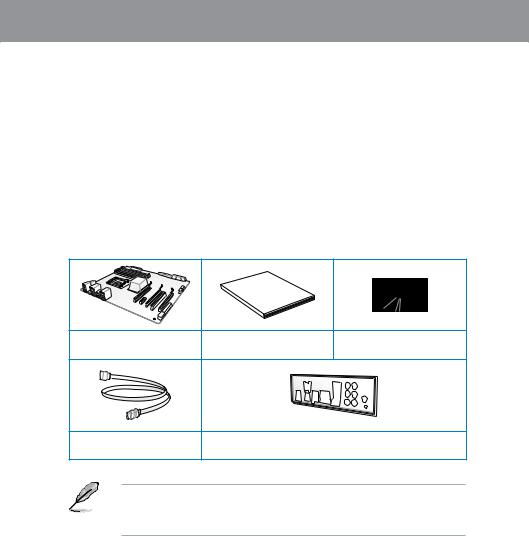
1.2Package contents
Check your motherboard package for the following items.
Chapter 1
Manual
User
|
ASUS P8B75-V motherboard |
User manual |
Support DVD |
|
2 x Serial ATA 6.0 Gb/s cables |
1 x I/O shield |
• If any of the above items is damaged or missing, contact your retailer.
• The illustrated items above are for reference only.Actual product specifications may vary with different models.

1 Chapter
1.3Special features
1.3.1Product highlights
LGA1155 socket for Intel® Second/Third Generation Core™ i7 / Core™ i5 / Core™ i3, Pentium®, and Celeron® processors
This motherboard supports the Intel® second/third generation Core™ i7 / Core™ i5 / Core™ i3, Pentium®, and Celeron® processors in the LGA1155 package, with memory and PCI Express controllers integrated to support 2-channel (4 DIMMs) DDR3 memory and 16 PCI Express 2.0 lanes.
Intel® B75 Express Chipset
The Intel® B75 Express Chipset is the latest single-chipset designed to support the 1155 socket Intel® 3rd/2nd generation Core™ i7 / Core™ i5 / Core™ i3 processors. It provides improved performance by utilizing serial point-to-point links, allowing increased bandwidth and stability. In addition, B75 chipset provides 4 USB 3.0 ports that retrieves data 10 times faster. Moreover, Intel® B75 Express Chipset also supports iGPU function, letting users enjoy the latest Intel integrated graphic performance.
PCI Express® 3.0
PCI Express® 3.0 (PCIe 3.0) is the latest PCI Express bus standard with improved encoding schemes that provide twice the performance of the current PCIe 2.0. The total bandwidth for a x16 link reaches a maximum of 32Gb/s, double the 16 Gb/s of PCIe 2.0 (in x16 mode). As such, PCIe 3.0 provides userss an unprecendented data speeds, combined with the convenience and seamless transition offerred by complete backward compatibility with PCIe 1.0 and PCIe 2.0 devices. PCIe 3.0 will become a must-have feature for users who wish to
improve and optimize graphic performance, as well as have the latest technology available to them.
* PCI 3.0 speed is supported by Intel® 3rd generation processors.
Quad-GPU CrossFireX™ Support
The motherboard’s powerful Intel® B75 platform optimizes PCIe allocation in multiple-GPU configurations of CrossFireX™. This allows you to enjoy a never before-experienced brand new gaming style.
Dual-Channel DDR3 2200(O.C.) / 2133(O.C.) / 2000(O.C.) / 1866(O.C.) / 1600 / 1333 / 1066 MHz Support
The motherboard supports DDR3 memory that features data transfer rates of DDR3 2200(O.
C.) / 2133(O.C.) / 2000(O.C.) / 1866(O.C.) / 1600 / 1333 / 1066 MHz to meet the higher bandwidth requirements of the latest 3D graphics, multimedia, and Internet applications. The dual-channel DDR3 architecture enlarges the bandwidth of your system memory to boost system performance.
Complete USB 3.0 Integration
ASUS facilitates the strategic USB 3.0 accessibility for both the front and rear panel – 4 USB 3.0 ports in total. Experience the latest plug & play connectivity at speeds up to 10 times faster than USB 2.0. The P8B75-V affords greater convenience to high speed connectivity.
|
1-2 |
Chapter 1: Product Introduction |

SATA 6.0 Gb/s Support
The Intel® B75 Express Chipset natively supports the next-generation Serial ATA (SATA) interface, delivering up to 6.0 Gb/s data transfer. ASUS provides SATA 6.0 Gb/s ports with enhanced scalability, faster data retrieval, and double the bandwidth of current bus systems.
100% All High-quality Conductive Polymer Capacitors
This motherboard uses all high-quality conductive polymer capacitors for durability, improved lifespan, and enhanced thermal capacity.
1.3.2ASUS Exclusive Features
DIGI+ VRM — Digital Power Design
All-new digital CPU power controls work perfectly together to match digital power signal
(SVID) requests from the CPU, with ultra-fast sensing and response efficiently delivering precision power. Accurate delivery reduces waste, and provides more stable CPU Vcore voltages. Users can adjust CPU PWM voltages and frequencies for various overclocking scenarios, with accurate input through UEFI BIOS tuning or the exclusive ASUS interface. This proprietary design increases overclocking headroom to push performance to its full potential.
MemOK!
MemOK! quickly ensures memory boot compatibility. This remarkable memory rescue tool requires a mere push of a button to patch memory issues. MemOK! determines fail-safe settings and dramatically improves your system boot success. Get your system up and running in no time!
USB 3.0 Boost
With USB 3.0 Boost technology, a USB device’s transmission speed is significantly increased, adding to an already impressive fast USB 3.0 transfer speed. ASUS software automatically accelerates data speeds for compatible USB 3.0 peripherals without the need for any user interaction.
Network iControl
ASUS Network iControl is an intuitive one-stop network control center that makes it easier for you to manage your network bandwidth and allows you to set, monitor, and schedule the bandwidth priorities for your network programs. It also allows you to automatically connect to a PPPoE network for a more convenient online experience.
AI Suite II
With its user-friendly interface, ASUS AI Suite II consolidates all the exclusive ASUS features into one simple to use software package. It allows you to supervise overclocking, energy management, fan speed control, and voltage and sensor readings. This all-in-one software offers diverse and ease to use functions, with no need to switch back and forth between different utilities.
Chapter 1

1 Chapter
ASUS TurboV
Feel the adrenaline rush of real-time OC-now a reality with the ASUS TurboV. This easy OC tool allows you to overclock without exiting or rebooting the OS; and its user-friendly interface makes overclock with just a few clicks away. Moreover, theASUS OC profiles in TurboV provides the best O.C. settings in different scenarios.
ASUS EPU
Tap into the world’s first real-time PC power saving chip through a simple onboard switch or Ai Suite II utility. Get total system-wide energy optimization by automatically detecting current
PC loadings and intelligently moderating power consumption. This also reduces fan noise and extends component longevity.
ASUS Anti-Surge Protection
This special design prevents expensive devices and the motherboard from damage caused by power surges from switching power supply (PSU).
1.3.3ASUS Quiet Thermal Solution
Fanless Design: stylish heatsink solution
The stylish heatsink features a 0-dB thermal solution that offers users a noiseless PC environment. Not only the beautiful shape upgrades the visual enjoyment for motherboard users, but also the heatsink design lowers the temperature of the chipset and power phase area through high efficient heat-exchange. Combined with usability and aesthetics, theASUS stylish heatsink will give users an extremely silent and cooling experience with the elegant appearance!
ASUS Fan Xpert
ASUS Fan Xpert intelligently allows you to adjust the CPU fan and chassis fan speeds according to different ambient temperatures caused by different climate conditions in different geographic regions and your PC’s loading. The built-in variety of useful profiles offer flexible controls of fan speed to achieve a quiet and cool environment.
1.3.4ASUS EZ DIY
ASUS UEFI BIOS
The newASUS UEFI BIOS is an Unified Extensible Firmware Interface that offers a userfriendly interface that goes beyond traditional keyboard-only BIOS controls to enable more flexible and convenient mouse input. Users can easily navigate the new UEFI BIOS with the same smoothness as their operating system. It natively supports hard drives larger than
2.2TB in 64-bit, with full storage space utilization, helping deliver far more exciting computing than traditional BIOS versions.
The exclusive EZ Mode displays frequently-accessed setup info, while the Advanced Mode is for experienced performance enthusiasts that demand far more intricate system settings. DRAM information.
|
1-4 |
Chapter 1: Product Introduction |

Supports hard drives over 2.2TB
ASUS UEFI BIOS natively supports hard drives larger than 2.2TB in 64-bit, with full storage space utilization helping deliver far more exciting computing than traditional BIOS versions.
ASUS MyLogo2™
This feature allows you to convert your favorite photo into a 256-color boot logo for a more colorful and vivid image on your screen.
ASUS CrashFree BIOS 3
ASUS CrashFree BIOS 3 is an auto-recovery tool that allows you to restore a corrupted BIOS file using the bundled support DVD or USB flash disk that contains the latest BIOS file.
ASUS EZ-Flash 2
ASUS EZ Flash 2 is a user-friendly utility that allows you to update the BIOS without using a bootable floppy disk or an OS-based utility.
ASUS Q-Slot
ASUS Q-Slot is designed to speed up and simplify the DIY process to enhance your DIY experience.
1.3.5Other special features
LucidLogix® Virtu Universal MVP™
LucidLogix® Virtu Universal MVP™ is designed for the Intel® Sandy Bridge platform’s powerful integrated graphics. Its GPU virtualization dynamically assigns tasks to the best available graphics resources based on power, performance and system load on Windows® 7 based PCs. It allows users to fully utilize the unique capabilities of advanced Sandy Bridge multimedia features alongside the high end 3D rendering performance provided by installed graphics cards. When no discrete graphics are needed, the graphics card is put in idle mode to lower utilization, heat, fan speed and power draw down to near zero, making the system more environmentally-friendly. For users with diverse needs, LucidLogix® Virtu GPU virtualization provides great flexibility and efficiency.
*LucidLogix® Virtu Universal MVP™ supports Windows® 7 operating system.
**Intel® Quick Sync Video feature is supported by 2nd/3rd generation Intel® Core™ processor family.
ErP Ready
The motherboard is European Union’s Energy-related Products (ErP) ready, and ErP requires products to meet certain energy efficiency requirement in regards to energy consumptions. This is in line withASUS vision of creating environment-friendly and energy-efficient products through product design and innovation to reduce carbon footprint of the product and thus mitigate environmental impacts.
Chapter 1

1 Chapter
|
1-6 |
Chapter 1: Product Introduction |

Chapter 2
|
Chapter 2: |
Hardware information |
2.1Before you proceed
Take note of the following precautions before you install motherboard components or change any motherboard settings.
• Unplug the power cord from the wall socket before touching any component.
• Before handling components, use a grounded wrist strap or touch a safely grounded object or a metal object, such as the power supply case, to avoid damaging them due to static electricity.
•Hold components by the edges to avoid touching the ICs on them.
•Whenever you uninstall any component, place it on a grounded antistatic pad or in the bag that came with the component.
•Before you install or remove any component, ensure that the ATX power supply is switched off or the power cord is detached from the power supply. Failure to do so may cause severe damage to the motherboard, peripherals, or components.
2 Chapter
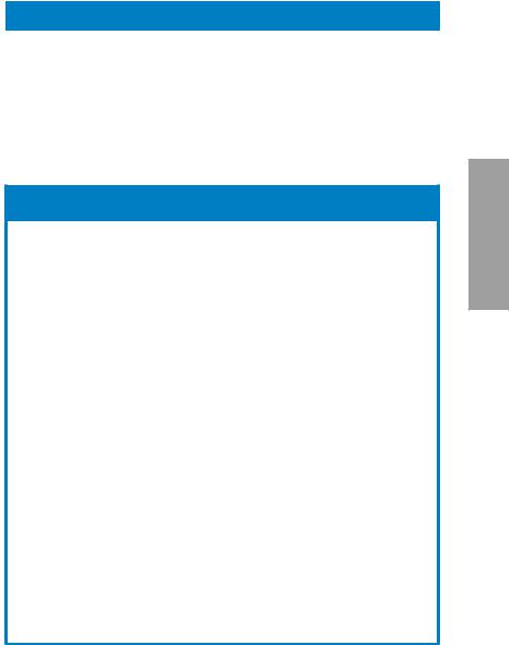
2.2Motherboard overview
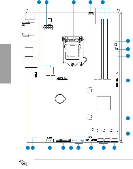
2.2.1Motherboard layout
|
1 |
2 |
3 |
1 |
4 |
|
21.9cm(8.6in) |
||||
|
KBMS |
CPU_FAN |
|||
|
DIGI |
||||
|
+VRM |
 DVI_VGA
USB34
USB3_12
LAN_USB12
AAFP
|
DDR3 DIMM A1 (64bit, 240-pin module) |
DDR3 DIMM A2 (64bit, 240-pin module) |
DDR3 DIMM B1 (64bit, 240-pin module) |
DDR3 DIMM B2 (64bit, 240-pin module) |
||
MemOK!
DRAM_LED EATXPWR
|
AUDIO |
CHA_FAN1 |
CHA_FAN2 |
7 |
|||||||||||||||||||||||||||||||||||||||
|
PCIEX1_1 |
P8B75-V |
|||||||||||||||||||||||||||||||||||||||||
|
30.5cm(12.0in) |
||||||||||||||||||||||||||||||||||||||||||
|
RTL |
||||||||||||||||||||||||||||||||||||||||||
|
8111E / F |
||||||||||||||||||||||||||||||||||||||||||
|
USB3_34 |
||||||||||||||||||||||||||||||||||||||||||
|
PCIEX16_1 |
||||||||||||||||||||||||||||||||||||||||||
|
Lithium Cell |
||||||||||||||||||||||||||||||||||||||||||
|
PCIEX1_2 |
||||||||||||||||||||||||||||||||||||||||||
|
CMOS Power |
||||||||||||||||||||||||||||||||||||||||||
|
Intel® |
||||||||||||||||||||||||||||||||||||||||||
|
B75 |
||||||||||||||||||||||||||||||||||||||||||
|
PCI1 |
||||||||||||||||||||||||||||||||||||||||||
|
Super |
||||||||||||||||||||||||||||||||||||||||||
|
I/O |
PCIEX16_2 |
8 |
||||||||||||||||||||||||||||||||||||||||
|
PCI2 |
8MB |
8MB |
||||||||||||||||||||||||||||||||||||||||
|
BIOS |
BIOS |
|||||||||||||||||||||||||||||||||||||||||
|
SATA3G_3 SATA3G_2 SATA3G_1 |
||||||||||||||||||||||||||||||||||||||||||
|
ALC |
||||||||||||||||||||||||||||||||||||||||||
|
887 |
SB_PWR |
9 |
||||||||||||||||||||||||||||||||||||||||
|
PCI3 |
||||||||||||||||||||||||||||||||||||||||||
|
SPDIF_OUT |
LPT |
USB78 |
USB56 |
PANEL |
CLRTC |
SATA3G_5 |
SATA3G_4 |
SATA6G_1 |
|
COM1 |
|
17 |
16 |
15 |
14 |
13 |
12 |
11 |
9 |
10 |
Refer to 2.2.8 Internal connectors and 2.3.10 Rear panel connection for more information about rear panel connectors and internal connectors.
|
2-2 |
Chapter 2: Hardware information |
![]()
Layout contents
|
Connectors/Jumpers/Slots |
Page |
|
|
1. |
CPU and chassis connectors (4-pin CPU_FAN, |
2-20 |
|
4-pin CHA_FAN1/2) |
||
|
2. |
ATX power connectors (24-pin EATXPWR, 8-pin EATX12V) |
2-22 |
|
3. |
Intel® LGA1155 CPU socket |
2-4 |
|
4. |
DDR3 DIMM slots |
2-5 |
|
5. |
MemOK! switch |
2-14 |
|
6. |
DRAM LED (DRAM_LED) |
2-15 |
|
7. |
USB 3.0 connector (20-1 pin USB3_34) |
2-15 |
|
8. |
Onboard LED (SB_PWR) |
2-15 |
|
9. |
Intel® B75 Serial ATA 3.0Gb/s connectors |
2-17 |
|
(7-pin SATA3G_1~5 [blue]) |
||
|
10. |
Intel® B75 Serial ATA 6.0Gb/s connector |
2-16 |
|
(7-pin SATA6G_1 [gray]) |
||
|
11. |
System panel connector (20-8 pin PANEL) |
2-23 |
|
12. |
USB 2.0 connectors (10-1 pin USB56, USB78) |
2.-18 |
|
13. |
Clear RTC RAM (3-pin CLRTC) |
2-13 |
|
14. |
LPT connector (26-1 pin LPT) |
2-16 |
|
15. |
Serial port connector (10-1 pin COM1) |
2-19 |
|
16. |
Digital audio connector (4-1 pin SPDIF_OUT) |
2-18 |
|
17. |
Front panel audio connector (10-1 pin AAFP) |
2-21 |
Chapter 2

2.2.2Central Processing Unit (CPU)
The motherboard comes with a surface mount LGA1155 socket designed for the Intel® 2nd/3rd Generation Core™ i7 / Core™ i5 / Core™ i3 processors.
2 Chapter

 P8B75-V
P8B75-V CPU socket LGA1155
Ensure that all power cables are unplugged before installing the CPU.
•The LGA1156 CPU is incompatible with the LGA1155 socket. DO NOT install a LGA1156 CPU on the LGA1155 socket.
•Upon purchase of the motherboard, ensure that the PnP cap is on the socket and the socket contacts are not bent. Contact your retailer immediately if the PnP cap is missing, or if you see any damage to the PnP cap/socket contacts/motherboard components. ASUS will shoulder the cost of repair only if the damage is shipment/ transit-related.
•Keep the cap after installing the motherboard. ASUS will process Return Merchandise
Authorization (RMA) requests only if the motherboard comes with the cap on the
LGA1155 socket.
•The product warranty does not cover damage to the socket contacts resulting from incorrect CPU installation/removal, or misplacement/loss/incorrect removal of the PnP cap.
|
2-4 |
Chapter 2: Hardware information |
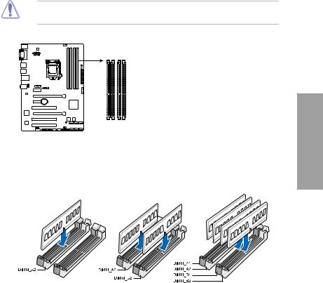
2.2.3System memory
The motherboard comes with four Double Data Rate 3 (DDR3) Dual Inline Memory Modules (DIMM) slots.
A DDR3 module is notched differently from a DDR or DDR2 module. DO NOT install a DDR or DDR2 memory module to the DDR3 slot.
|
DIMM A1 |
DIMM A2 |
DIMM B1 DIMM B2 |
|
P8B75-V |
||
|
P8B75-V 240-pin DDR3 DIMM sockets |
Recommended memory configurations
Chapter 2
Memory configurations
You may install 1GB, 2GB, 4GB and 8GB unbuffered and non ECC DDR3 DIMMs into the DIMM sockets.
2 Chapter
•You may install varying memory sizes in ChannelAand Channel B. The system maps the total size of the lower-sized channel for the dual-channel configuration.Any excess memory from the higher-sized channel is then mapped for single-channel operation.
•According to Intel CPU spec, DIMM voltage below 1.65V is recommended to protect the CPU.
•Always install DIMMs with the same CAS latency. For optimum compatibility, we recommend that you obtain memory modules from the same vendor.
•Due to the memory address limitation on 32-bit Windows OS, when you install 4GB or more memory on the motherboard, the actual usable memory for the OS can be about 3GB or less. For effective use of memory, we recommend that you do any of the following:
—Use a maximum of 3GB system memory if you are using a 32-bit Windows OS.
—Install a 64-bit Windows OS when you want to install 4GB or more on the motherboard.
For more details, refer to the Microsoft® support site at http://support.microsoft.com/kb/929605/en-us.
•This motherboard does not support DIMMs made up of 512Mb (64MB) chips or less (Memory chip capacity counts in Megabit, 8 Megabit/Mb = 1 Megabyte/MB).
•The maximum 32GB memory capacity can be supported with 8GB or above DIMMs. ASUS will update the memory QVL once the DIMMs are available in the market.
•The default memory operation frequency is dependent on its Serial Presence Detect (SPD), which is the standard way of accessing information from a memory module. Under the default state, some memory modules for overclocking may operate at a lower frequency than the vendor-marked value. To operate at the vendor-marked
or at a higher frequency, refer to section 3.4 Ai Tweaker menu for manual memory frequency adjustment.
•For system stability, use a more efficient memory cooling system to support a full memory load (4 DIMMs) or overclocking condition.
|
2-6 |
Chapter 2: Hardware information |
P8B75-V Motherboard Qualified Vendors Lists (QVL)
DDR3 1866 (O.C.) MHz capability
|
Vendors |
Part No. |
Size |
SS/DS |
Chip |
Chip |
Timing |
Voltage |
DIMM socket support |
|||
|
Brand |
No. |
(Optional) |
|||||||||
|
A |
B |
C |
|||||||||
|
CORSAIR |
CMT4GX3M2 |
4GB |
DS |
— |
— |
9-9-9-24 |
1.65V |
• |
• |
• |
|
|
A1866C9(XMP) |
(2 x 2GB) |
||||||||||
|
CORSAIR |
CMZ8GX3M2 |
8GB |
DS |
— |
— |
9-10-9-27 |
1.50V |
• |
• |
• |
|
|
A1866C9(XMP) |
(2 x 4GB) |
||||||||||
|
G.SKILL |
F3-14900CL |
8GB |
DS |
— |
— |
9-10-9-28 |
1.5V |
• |
• |
• |
|
|
9D-8GBXL(XMP) |
(2 x 4GB) |
||||||||||
|
G.SKILL |
F3-14900CL |
8GB |
DS |
— |
— |
9-9-9-24 |
1.6V |
• |
• |
• |
|
|
9Q-8GBXL(XMP) |
(2GBx4) |
||||||||||
|
KINGSTON |
KHX1866C9 |
3GB |
SS |
— |
— |
— |
1.65V |
• |
• |
• |
|
|
D3T1K3/3GX(XMP) |
(3 x 1GB) |
||||||||||
|
KINGSTON |
KHX1866C9 |
6GB |
DS |
— |
— |
— |
1.65V |
• |
• |
• |
|
|
D3T1K3/6GX(XMP) |
(3 x 2GB) |
DDR3 1333 MHz capability
|
Vendors |
Part No. |
Size |
SS/ |
Chip |
Chip No. |
Timing |
Voltage |
DIMM socket |
||||
|
DS |
Brand |
support |
||||||||||
|
(Optional) |
||||||||||||
|
A |
B |
C |
||||||||||
|
A-DATA |
AD31333001GOU |
1GB |
SS |
A-Data |
AD30908C8 |
— |
— |
• |
• |
• |
||
|
D-151C E0906 |
||||||||||||
|
A-DATA |
AD3U1333C2G9 |
2GB |
SS |
A-DATA |
3CCD-1509H |
— |
— |
• |
• |
• |
||
|
NA1126L |
||||||||||||
|
A-DATA |
AD63I1B0823EV |
2GB |
SS |
A-Data |
3CCA-1509A |
— |
— |
• |
• |
• |
||
|
A-DATA |
AM2U139C2P1 |
2GB |
SS |
ADATA |
3CCD-1509A |
— |
— |
• |
• |
• |
||
|
EL1127T |
||||||||||||
|
A-DATA |
AX3U1333C2G9-BP |
2GB |
SS |
— |
— |
— |
— |
• |
• |
• |
||
|
A-DATA |
AXDU1333G |
4GB |
SS |
— |
— |
9-9-9-24 |
1.25V-1.35V |
• |
• |
• |
||
|
C2G9-2G(XMP) |
(2 x 2GB) |
(low voltage) |
||||||||||
|
A-DATA |
AD63I1C1624EV |
4GB |
DS |
A-Data |
3CCA-1509A |
— |
— |
• |
• |
• |
||
|
A-DATA |
AM2U139C4P2 |
4GB |
DS |
ADATA |
3CCD-1509A |
— |
— |
• |
• |
• |
||
|
EL1127T |
||||||||||||
|
A-DATA |
SU3U1333W8G9-B |
8GB |
DS |
ELPIDA |
J4208BASE-DJ-F |
— |
— |
• |
• |
• |
||
|
Apacer |
78.A1GC6.9L1 |
2GB |
DS |
Apacer |
AM5D5808 |
— |
— |
• |
• |
• |
||
|
DEWSBG |
||||||||||||
|
Apacer |
78.A1GC6.9L1 |
2GB |
DS |
Apacer |
AM5D5808 |
9 |
— |
• |
• |
• |
||
|
FEQSBG |
||||||||||||
|
Apacer |
AU02GFA33C9NBGC |
2GB |
DS |
Apacer |
AM5D5808 |
— |
— |
• |
• |
• |
||
|
APQSBG |
||||||||||||
|
Apacer |
78.B1GDE.9L10C |
4GB |
DS |
Apacer |
AM5D5908C |
— |
— |
• |
• |
• |
||
|
EHSBG |
||||||||||||
|
CORSAIR |
CM3X1024-1333C9 |
1GB |
SS |
— |
— |
9-9-9-24 |
1.60V |
• |
• |
• |
||
|
CORSAIR |
TR3X3G1333C9 G |
3GB |
SS |
— |
— |
9-9-9-24 |
1.50V |
• |
• |
• |
||
|
(3 x 1GB) |
||||||||||||
|
CORSAIR |
CMD24GX3M6 |
24GB |
DS |
— |
— |
9-9-9-24 |
1.60V |
• |
• |
• |
||
|
A1333C9(XMP) |
(6x4GB) |
|||||||||||
|
CORSAIR |
TW3X4G1333C9D G |
4GB |
DS |
— |
— |
9-9-9-24 |
1.50V |
• |
• |
• |
||
|
(2 x 2GB) |
||||||||||||
|
CORSAIR |
CM3X4GA1333C9N2 |
4GB |
DS |
CORSAIR |
256MBDCJG |
9-9-9-24 |
— |
• |
• |
• |
||
|
ELC0401136 |
||||||||||||
|
CORSAIR |
CMX4GX3M1A1333C9 |
4GB |
DS |
— |
— |
9-9-9-24 |
1.50V |
• |
• |
• |
||
|
CORSAIR |
CMD8GX3M4A1333C7 |
8GB |
DS |
— |
— |
7-7-7-20 |
1.60V |
• |
• |
• |
||
|
(4 x 2GB) |
||||||||||||
|
Crucial |
CT12864BA1339.8FF |
1GB |
SS |
Micron |
9FF22D9KPT |
9 |
— |
• |
• |
• |
||
|
Crucial |
CT25664BA1339.16FF |
2GB |
DS |
Micron |
9KF27D9KPT |
9 |
— |
• |
• |
• |
||
|
Crucial |
BL25664BN |
6GB |
DS |
— |
— |
7-7-7-24 |
1.65V |
• |
• |
• |
||
|
1337.16FF (XMP) |
(3 x 2GB) |
|||||||||||
|
ELPIDA |
EBJ10UE8EDF0-DJ-F |
1GB |
SS |
ELPIDA |
J1108EDS |
— |
1.35V |
• |
• |
• |
||
|
E-DJ-F |
(low voltage) |
|||||||||||
|
G.SKILL |
F3-10600CL8 |
1GB |
SS |
G.SKILL |
— |
— |
— |
• |
• |
• |
||
|
D-2GBHK(XMP) |
||||||||||||
|
G.SKILL |
F3-10600CL9 |
2GB |
SS |
— |
— |
9-9-9-24 |
1.5V |
• |
• |
• |
||
|
D-2GBNQ |
(2 x 1GB) |
|||||||||||
|
G.SKILL |
F3-10666CL7 |
3GB |
SS |
— |
— |
7-7-7-18 |
1.5~1.6V |
• |
• |
• |
||
|
T-3GBPK(XMP) |
(3 x 1GB) |
(continued on the next page)
Chapter 2

2 Chapter
DDR3 1333 MHz capability
|
Vendor |
Part No. |
Size |
SS/ |
Chip Brand |
Chip No. |
Timing |
Voltage |
DIMM socket |
||
|
DS |
support |
|||||||||
|
A |
B |
C |
||||||||
|
G.SKILL |
F3-10666CL8 |
4GB |
DS |
— |
— |
8-8-8-8-24 |
XMP 1.35V |
• |
• |
• |
|
D-4GBECO(XMP) |
(2 x 2GB) |
|||||||||
|
G.SKILL |
F3-10666CL7 |
8GB |
DS |
— |
— |
7-7-7-21 |
1.5V |
• |
• |
• |
|
D-8GBRH(XMP) |
(2 x 4GB) |
|||||||||
|
GEIL |
GV32GB1333C9DC |
2GB |
DS |
— |
— |
9-9-9-24 |
1.5V |
• |
• |
• |
|
(2 x 1GB) |
||||||||||
|
GEIL |
GG34GB1333C9DC |
4GB |
DS |
GEIL |
GL1L128 |
9-9-9-24 |
1.3V |
• |
• |
• |
|
(2 x 2GB) |
M88BA12N |
(low voltage) |
||||||||
|
GEIL |
GV34GB1333C9DC |
4GB |
DS |
— |
— |
9-9-9-24 |
1.5V |
• |
• |
• |
|
(2 x 2GB) |
||||||||||
|
GEIL |
GVP34GB1333C7DC |
4GB |
DS |
— |
— |
7-7-7-24 |
1.5V |
• |
• |
• |
|
(2 x 2GB) |
||||||||||
|
Hynix |
HMT112U6TFR8A-H9 |
1GB |
SS |
Hynix |
H5TC1G83 |
— |
1.35V |
• |
• |
• |
|
TFRH9A |
(low voltage) |
|||||||||
|
Hynix |
HMT325U6BFR8C-H9 |
2GB |
SS |
Hynix |
H5TQ2G83 |
— |
— |
• |
• |
• |
|
BFRH9C |
||||||||||
|
Hynix |
HMT125U6TFR8A-H9 |
2GB |
DS |
Hynix |
H5TC1G83 |
— |
1.35V |
• |
• |
• |
|
TFRH9A |
(low voltage) |
|||||||||
|
Hynix |
HMT351U6 |
4GB |
DS |
Hynix |
H5TQ2G83 |
— |
— |
• |
• |
• |
|
BFR8C-H9 |
BFRH9C |
|||||||||
|
KINGMAX |
FLFD45F-B8 |
1GB |
SS |
KINGMAX |
KKB8FNW |
— |
— |
• |
• |
• |
|
KL9 NAES |
BFGNX-27A |
|||||||||
|
KINGMAX |
FLFE85F-C8 |
2GB |
SS |
KINGMAX |
KFC8FMF |
— |
— |
• |
• |
• |
|
KF9 CAES |
XF-DXX-15A |
|||||||||
|
KINGMAX |
FLFE85F-C8 |
2GB |
SS |
KINGMAX |
KFC8FNL |
— |
— |
• |
• |
• |
|
KL9 NAES |
XF-DXX-15A |
|||||||||
|
KINGMAX |
FLFE85F-C8 |
2GB |
SS |
KINGMAX |
KFC8FNM |
— |
— |
• |
• |
• |
|
KM9 NAES |
XF-BXX-15A |
|||||||||
|
KINGMAX |
FLFE85F-B8 |
2GB |
DS |
KINGMAX |
KKB8FNW |
— |
— |
• |
• |
• |
|
KL9 NEES |
BFGNX-26A |
|||||||||
|
KINGMAX |
FLFF65F-C8 |
4GB |
DS |
KINGMAX |
KFC8FNLX |
— |
— |
• |
• |
• |
|
KL9 NEES |
F-DXX-15A |
|||||||||
|
KINGMAX |
FLFF65F-C8 |
4GB |
DS |
KINGMAX |
KFC8FNMX |
— |
— |
• |
• |
• |
|
KM9 NEES |
F-BXX-15A |
|||||||||
|
KINGSTON |
KVR1333 |
1GB |
SS |
ELPIDA |
J1108BD |
9 |
1.5V |
• |
• |
• |
|
D3N9/1G |
BG-DJ-F |
|||||||||
|
KINGSTON |
KVR1333D3 |
2GB |
SS |
Micron |
IID77 D9LGK |
— |
1.5V |
• |
• |
• |
|
S8N9/2G |
||||||||||
|
KINGSTON |
KVR1333D3 |
2GB |
SS |
ELPIDA |
J2108BC |
— |
1.5V |
• |
• |
• |
|
S8N9/2G-SP |
SE-DJ-F |
|||||||||
|
KINGSTON |
KVR1333 |
2GB |
DS |
ELPIDA |
J1108BF |
9 |
1.5V |
• |
• |
• |
|
D3N9/2G |
BG-DJ-F |
|||||||||
|
KINGSTON |
KVR1333 |
2GB |
DS |
KTC |
D1288JPN |
9 |
1.5V |
• |
• |
• |
|
D3N9/2G |
DPLD9U |
|||||||||
|
KINGSTON |
KVR1333 |
2GB |
DS |
ELPIDA |
J1108BD |
9 |
1.5V |
• |
• |
• |
|
D3N9/2G |
SE-DJ-F |
|||||||||
|
KINGSTON |
KVR1333 |
2GB |
DS |
KTC |
D1288JEM |
— |
1.5V |
• |
• |
• |
|
D3N9/2G-SP |
FNGD9U |
|||||||||
|
KINGSTON |
KVR1333 |
2GB |
DS |
KINGSTON |
D1288JPS |
— |
1.5V |
• |
• |
• |
|
D3N9/2G-SP |
FPGD9U |
|||||||||
|
KINGSTON |
KHX1333C7 |
4GB |
DS |
— |
— |
7 |
1.65V |
• |
• |
• |
|
D3K2/4GX(XMP) |
(2 x 2GB) |
|||||||||
|
KINGSTON |
KHX1333C9 |
4GB |
DS |
— |
— |
9 |
XMP 1.25V |
• |
• |
• |
|
D3UK2/4GX(XMP) |
(2 x 2GB) |
|||||||||
|
KINGSTON |
KVR1333 |
4GB |
DS |
ELPIDA |
J2108BC |
9 |
1.5V |
• |
• |
• |
|
D3N9/4G |
SE-DJ-F |
|||||||||
|
KINGSTON |
KVR1333 |
4GB |
DS |
ELPIDA |
J2108BC |
— |
1.5V |
• |
• |
• |
|
D3N9/4G |
SE-DJ-F |
|||||||||
|
KINGSTON |
KVR1333 |
4GB |
DS |
KTC |
D2568JE |
— |
1.5V |
• |
• |
• |
|
D3N9/4G |
NCNGD9U |
|||||||||
|
KINGSTON |
KVR1333 |
4GB |
DS |
Hynix |
H5TQ2G |
— |
— |
• |
• |
• |
|
D3N9/4G |
83AFR |
|||||||||
|
KINGSTON |
KVR1333 |
4GB |
DS |
KINGSTON |
D2568JEN |
— |
1.5V |
• |
• |
• |
|
D3N9/4G-SP |
CPGD9U |
|||||||||
|
Micron |
MT8JTF12864 |
1GB |
SS |
Micron |
9FF22D9KPT |
9 |
— |
• |
• |
• |
|
AZ-1G4F1 |
||||||||||
|
Micron |
MT8JTF25664 |
2GB |
SS |
Micron |
OJD12D9LGK |
— |
— |
• |
• |
• |
|
AZ-1G4D1 |
||||||||||
|
Micron |
MT8JTF25664 |
2GB |
SS |
MICRON |
IJM22 D9PFJ |
— |
— |
• |
• |
• |
|
AZ-1G4M1 |
||||||||||
|
Micron |
MT16JTF25664 |
2GB |
DS |
Micron |
9KF27D9KPT |
9 |
— |
• |
• |
• |
|
AZ-1G4F1 |
(continued on the next page)
|
2-8 |
Chapter 2: Hardware information |

DDR3 1333 MHz capability
|
Vendor |
Part No. |
Size |
SS/ |
Chip Brand |
Chip No. |
Timing |
Voltage |
DIMM socket |
|||
|
DS |
support |
||||||||||
|
A |
B |
C |
|||||||||
|
Micron |
MT16JTF51264 |
4GB |
DS |
Micron |
OLD22D9LGK |
— |
— |
• |
• |
• |
|
|
AZ-1G4D1 |
|||||||||||
|
NANYA |
NT4GC64B8 |
4GB |
DS |
NANYA |
NT5CB256 |
— |
— |
• |
• |
• |
|
|
HG0NF-CG |
M8GN-CG |
||||||||||
|
PSC |
AL7F8G73F-DJ2 |
1GB |
SS |
PSC |
A3P1GF3FGF |
— |
— |
• |
• |
• |
|
|
PSC |
AL8F8G73F-DJ2 |
2GB |
DS |
PSC |
A3P1GF3FGF |
— |
— |
• |
• |
• |
|
|
SAMSUNG |
M378B287 |
1GB |
SS |
SAMSUNG |
K4B1G0846F |
— |
— |
• |
• |
• |
|
|
3FHS-CH9 |
|||||||||||
|
SAMSUNG |
M378B577 |
2GB |
SS |
SAMSUNG |
K4B2G0846D |
— |
— |
• |
• |
• |
|
|
3DH0-CH9 |
|||||||||||
|
SAMSUNG |
M378B567 |
2GB |
DS |
SAMSUNG |
K4B1G0846F |
— |
— |
• |
• |
• |
|
|
3FH0-CH9 |
|||||||||||
|
SAMSUNG |
M378B527 |
4GB |
DS |
SAMSUNG |
K4B2G0846C |
— |
— |
• |
• |
• |
|
|
3CH0-CH9 |
|||||||||||
|
Super Talent |
W1333UA1GH |
1GB |
SS |
Hynix |
H5TQ1G83TFR |
9 |
— |
• |
• |
• |
|
|
Super Talent |
W1333UB2GS |
2GB |
DS |
SAMSUNG |
K4B1G0846F |
9 |
— |
• |
• |
• |
|
|
Super Talent |
W1333UB4GS |
4GB |
DS |
SAMSUNG |
K4B2G0846C |
— |
— |
• |
• |
• |
|
|
Super Talent |
W1333UX6GM |
6GB |
DS |
Micron |
0BF27D9KPT |
9-9-9-24 |
1.5V |
• |
• |
• |
|
|
(3x 2GB) |
|||||||||||
|
Transcend |
JM1333KLN-2G |
2GB |
SS |
Micron |
0YD77D9LGK |
— |
— |
• |
• |
• |
|
|
Transcend |
JM1333KLN-2G |
2GB |
SS |
Hynix |
H5TQ2G83BZRH9C |
— |
— |
• |
• |
• |
|
|
Century |
PC3-10600 |
1GB |
SS |
NANYA |
NT5CB128M8DN-CF |
— |
— |
• |
• |
• |
|
|
DDR3-1333 9-9-9 |
|||||||||||
|
Elixir |
M2F2G64C |
2GB |
SS |
Elixir |
N2CB2G80GN-CG |
— |
— |
• |
• |
• |
|
|
B88G7N-CG |
|||||||||||
|
Elixir |
M2F4G64C |
4GB |
DS |
Elixir |
N2CB2G80BN-CG |
— |
— |
• |
• |
• |
|
|
B8HB5N-CG |
|||||||||||
|
KINGSHARE |
KSRPCD3 |
2GB |
DS |
PATRIOT |
PM128M8D385-15 |
— |
— |
• |
• |
• |
|
|
13332G |
|||||||||||
|
KINGSTEK |
KSTD3P |
2GB |
SS |
MICRON |
PE911-125E |
— |
— |
• |
• |
• |
|
|
C-10600 |
|||||||||||
|
Kingtiger |
2GB DIMM |
2GB |
DS |
SAMSUNG |
SEC 904 HCH9 |
— |
— |
• |
• |
• |
|
|
PC3-10666 |
K4B1G0846D |
||||||||||
|
Kingtiger |
KTG2G13 |
2GB |
DS |
— |
— |
— |
— |
• |
• |
• |
|
|
33PG3 |
|||||||||||
|
MARKVISION |
BMD32048M |
2GB |
DS |
MARKVISION |
M3D1288P-13 |
— |
— |
• |
• |
• |
|
|
1333C9-1123 |
|||||||||||
|
MARKVISION |
BMD34096M |
4GB |
DS |
MARKVISION |
M3D2568E-13 |
— |
— |
• |
• |
• |
|
|
1333C9-1124 |
|||||||||||
|
PATRIOT |
PSD31G13332 |
1GB |
DS |
PATRIOT |
PM64M8D38U-15 |
— |
— |
• |
• |
• |
|
|
PATRIOT |
PSD32G13332H |
2GB |
DS |
— |
— |
— |
— |
• |
• |
• |
|
|
RAMAXEL |
RMR1870E |
2GB |
DS |
ELPIDA |
J1108BDBG-DJ-F |
— |
— |
• |
• |
• |
|
|
D48E8F-1333 |
|||||||||||
|
RAMAXEL |
RMR1870EC |
4GB |
DS |
ELPIDA |
J2108BCSE-DJ-F |
— |
— |
• |
• |
• |
|
|
58E9F-1333 |
|||||||||||
|
RiDATA |
E304459CB1 |
4GB |
DS |
RiDATA |
N/A |
9 |
— |
• |
• |
• |
|
|
AG32Cf |
|||||||||||
|
SanMax |
SMD-4G68 |
4GB |
DS |
HYNIX |
H5TQ2G83BFR H9C |
— |
— |
• |
• |
• |
|
|
H1P-13HZ |
|||||||||||
|
SILICON |
SP001GBL |
1GB |
SS |
NANYA |
NT5CB128M8AN-CG |
9 |
— |
• |
• |
• |
|
|
POWER |
TU133S01 |
||||||||||
|
SILICON |
SP001GBL |
1GB |
SS |
Elixir |
N2CB1680AN-C6 |
9 |
— |
• |
• |
• |
|
|
POWER |
TU133S02 |
||||||||||
|
SILICON |
SP002GBLT |
2GB |
DS |
Elixir |
N2CB1680AN-C6 |
9 |
— |
• |
• |
• |
|
|
POWER |
U133S02 |
||||||||||
|
UMAX |
E41302GP |
2GB |
DS |
UMAX |
U2S24D30TP-13 |
— |
— |
• |
• |
• |
|
|
0-73BDB |
|||||||||||
|
WINTEC |
3WVS31333-2G- |
2GB |
DS |
AMPO |
AM3420803-13H |
— |
— |
• |
• |
• |
|
|
CNR |
Chapter 2
2 Chapter
DDR3 1066 MHz capability
|
Vendors |
Part No. |
Size |
SS/DS |
Chip |
Chip No. |
Timing |
Voltage |
DIMM socket |
||
|
Brand |
support (Optional) |
|||||||||
|
A |
B |
C |
||||||||
|
Crucial |
CT12864B |
1GB |
SS |
Micron |
9GF22D9KPT |
7 |
— |
• |
• |
• |
|
A1067.8FF |
||||||||||
|
Crucial |
CT25664B |
2GB |
DS |
Micron |
9HF22D9KPT |
7 |
— |
• |
• |
• |
|
A1067.16FF |
||||||||||
|
ELPIDA |
EBJ10UE8E |
1GB |
SS |
ELPIDA |
J1108EDSE-DJ-F |
— |
1.35V |
• |
• |
• |
|
DF0-AE-F |
(low |
|||||||||
|
voltage) |
||||||||||
|
ELPIDA |
EBJ21UE8E |
2GB |
DS |
ELPIDA |
J1108EDSE-DJ-F |
— |
1.35V |
• |
• |
• |
|
DF0-AE-F |
(low |
|||||||||
|
voltage) |
||||||||||
|
KINGSTON |
KVR1066 |
1GB |
SS |
ELPIDA |
J1108BFSE-DJ-F |
7 |
1.5V |
• |
• |
• |
|
D3N7/1G |
||||||||||
|
KINGSTON |
KVR1066 |
2GB |
DS |
ELPIDA |
J1108BDSE-DJ-F |
7 |
1.5V |
• |
• |
• |
|
D3N7/2G |
||||||||||
|
KINGSTON |
KVR1066 |
4GB |
DS |
Hynix |
H5TQ2G83AFR |
7 |
1.5V |
• |
• |
• |
|
D3N7/4G |
||||||||||
|
Micron |
MT8JTF12864 |
1GB |
SS |
Micron |
9GF22D9KPT |
7 |
— |
• |
• |
• |
|
AZ-1G1F1 |
||||||||||
|
Micron |
MT16JTF25664 |
2GB |
DS |
Micron |
9HF22D9KPT |
7 |
— |
• |
• |
• |
|
AZ-1G1F1 |
||||||||||
|
Kingtiger |
2GB DIMM |
2GB |
DS |
Hynix |
H5TQ1G83AFP |
— |
— |
• |
• |
• |
|
PC3-8500 |
G7C |
Side(s): SS — Single-sided DS — Double-sided
DIMM support:
•1 DIMM: Supports one (1) module inserted into any slot as Single-channel memory configuration. We suggest that you install the module into A2 slot.
•2 DIMMs: Supports two (2) modules inserted into either the blue slots or the black slots as one pair of Dual-channel memory configuration. We suggest that you install the modules into slots A2 and B2 for better compatibility.
•4 DIMMs: Supports four (4) modules inserted into both the blue and black slots as two pairs of Dual-channel memory configuration.
Visit the ASUS website for the latest QVL.
|
2-10 |
Chapter 2: Hardware information |

2.2.4Expansion slots
Ensure to unplug the power cord before adding or removing expansion cards. Failure to do so may cause you physical injury and damage motherboard components.


 P8B75-V
Slot No. Slot Description
1PCIe 2.0 x1_1 slot
2PCIe 3.0 x16_1 slot (at x16 mode)
3PCIe 2.0 x1_2 slot
4PCI slot 1
5PCIe 2.0 x16_2 slot (at x4 mode, compatible with PCIe x1 and x4 devices)
6PCI slot 2
7PCI slot 3
|
VGA configuration |
PCI Express operating mode |
||
|
PCIe 3.0 x16_1 |
PCIe 2.0 x16_2 |
||
|
Single VGA/PCIe card |
x16 (Recommend for single VGA) |
N/A |
|
|
Dual VGA/PCIe card |
|||
|
x16 |
x4 |
Chapter 2
2 Chapter
•In single VGA card mode, use the PCIe 3.0 x16_1 slot (blue) for a PCI Express x16 graphics card to get better performance.
•We recommend that you provide sufficient power when running CrossFireX™ mode.
Refer to page 2-23 for details.
•Connect a chassis fan to the motherboard connector labeled CHA_FAN1/2 when using multiple graphics cards for better thermal environment. See page 2-30 for details.
IRQ assignments for this motherboard
|
Intel PCH SATA |
A |
B |
C |
D |
E |
F |
G |
H |
|
|
– |
– |
– |
shared |
– |
– |
– |
– |
||
|
Controller #0 |
|||||||||
|
Intel PCH SATA |
– |
– |
– |
shared |
– |
– |
– |
– |
|
|
Controller #1 |
|||||||||
|
PCIE x16_1 |
shared |
– |
– |
– |
– |
– |
– |
– |
|
|
PCIE x16_2 |
shared |
– |
– |
– |
– |
– |
– |
– |
|
|
RTL8111E / F |
shared |
– |
– |
– |
– |
– |
– |
– |
|
|
PCIE x1_1 |
– |
shared |
– |
– |
– |
– |
– |
– |
|
|
PCIE x1_2 |
– |
– |
shared |
– |
– |
– |
– |
– |
|
|
PCI slot 1 |
shared |
– |
– |
– |
– |
– |
– |
– |
|
|
PCI slot 2 |
– |
shared |
– |
– |
– |
– |
– |
– |
|
|
PCI slot 3 |
– |
– |
shared |
– |
– |
– |
– |
– |
|
2-12 |
Chapter 2: Hardware information |
![]()
2.2.5Jumper
Clear RTC RAM (3-pin CLRTC)
This jumper allows you to clear the Real Time Clock (RTC) RAM in CMOS. You can clear the CMOS memory of date, time, and system setup parameters by erasing the CMOS RTC RAM data. The onboard button cell battery powers the RAM data in CMOS, which include system setup information such as system passwords.

 P8B75-V
CLRTC
|
1 |
2 |
2 |
3 |
|
Normal |
Clear RTC |
||
|
(Default) |
P8B75-V Clear RTC RAM
To erase the RTC RAM:
1.Turn OFF the computer and unplug the power cord.
2.Move the jumper cap from pins 1-2 (default) to pins 2-3. Keep the cap on pins 2-3 for about 5-10 seconds, then move the cap back to pins 1-2.
3.Plug the power cord and turn ON the computer.
4.Hold down the <Del> key during the boot process and enter BIOS setup to reenter data.
Except when clearing the RTC RAM, never remove the cap on CLRTC jumper default position. Removing the cap will cause system boot failure!
•If the steps above do not help, remove the onboard battery and move the jumper again to clear the CMOS RTC RAM data. After clearing the CMOS, reinstall the battery.
•You do not need to clear the RTC when the system hangs due to overclocking. For system failure due to overclocking, use the CPU Parameter Recall (C.P.R.) feature. Shut down and reboot the system, then the BIOS automatically resets parameter settings to default values.
Chapter 2

2.2.6Onboard switches
Onboard switches allow you to fine-tune performance when working on a bare or opencase system. This is ideal for overclockers and gamers who continually change settings to enhance system performance.
1.MemOK! switch
Installing DIMMs that are incompatible with the motherboard may cause system boot failure, and the DRAM_LED near the MemOK! switch lights continuously. Press and hold the MemOK! switch until the DRAM_LED starts blinking to begin automatic memory compatibility tuning for successful boot.
2 Chapter

 P8B75-V
P8B75-V MemOK! switch
•Refer to section 2.2.7 Onboard LEDs for the exact location of the DRAM_LED.
•The DRAM_LED also lights when the DIMM is not properly installed. Turn off the system and reinstall the DIMM before using the MemOK! function.
•The MemOK! switch does not function under Windows OS environment.
•During the tuning process, the system loads and tests failsafe memory settings. It takes about 30 seconds for the system to test one set of failsafe settings. If the test fails, the system reboots and test the next set of failsafe settings. The blinking speed of the DRAM_LED increases, indicating different test processes.
•Due to memory tuning requirement, the system automatically reboots when each timing set is tested. If the installed DIMMs still fail to boot after the whole tuning process, the DRAM_LED lights continuously. Replace the DIMMs with ones recommended in the Memory QVL (Qualified Vendors Lists) in this user manual or on the ASUS website at www.asus.com.
•If you turn off the computer and replace DIMMs during the tuning process, the system continues memory tuning after turning on the computer. To stop memory tuning, turn off the computer and unplug the power cord for about 5–10 seconds.
•If your system fail to boot due to BIOS overclocking, press the MemOK! switch to boot and load BIOS default settings. A message will appear during POST reminding you that the BIOS has been restored to its default settings.
•We recommend that you download and update to the latest BIOS version from the ASUS website at www.asus.com after using the MemOK! function.
|
2-14 |
Chapter 2: Hardware information |

2.2.7Onboard LEDs
1.Standby Power LED
The motherboard comes with a standby power LED that lights up to indicate that the system is ON, in sleep mode, or in soft-off mode. This is a reminder that you should shut down the system and unplug the power cable before removing or plugging in any motherboard component. The illustration below shows the location of the onboard LED.
P8B75-V
SB_PWR
ON OFF
Standby Power Powered Off
P8B75-V Onboard LED
2.DRAM LED
DRAM LED checks the DRAM in sequence during motherboard booting process. If an error is found , the LED next to the error device will continue lighting until the problem is solved. This user-friendly design provides an intuitional way to locate the root problem within a second.

 DRAM LED

 P8B75-V
P8B75-V DRAM LED
Chapter 2

2.2.8Internal connectors
1.Intel® B75 Serial ATA 6.0 Gb/s connector (7-pin SATA6G_1 [gray])
This connectors connect to Serial ATA 6.0 Gb/s hard disk drives via Serial ATA 6.0 Gb/s signal cables.
2 Chapter

 P8B75-V
SATA6G_1
GNDRSATA RXP1_RSATA RXN1_GNDRSATA_TXN1RSATA TXP1_GND
P8B75-V SATA 6.0Gb/s connector
When using NCQ, set the SATA Mode Selection in the BIOS to [AHCI]. Refer to section
3.5.3 SATA Configuration for details.
2. LPT connector (26-1 pin LPT)
The LPT (Line Printing Terminal) connector supports devices such as a printer. LPT standardizes as IEEE 1284, which is the parallel port interface on IBM PC-compatible computers.
|
LPT |
|||
|
SLCT |
|||
|
GND |
PE |
||
|
GND |
BUSY |
||
|
GND |
ACK# |
||
|
P8B75-V |
GND |
PD7 |
|
|
GND |
PD6 |
||
|
GND |
PD5 |
||
|
GND |
PD4 |
||
|
GND |
PD3 |
||
|
SLIN# |
PD2 |
||
|
INIT# |
PD1 |
||
|
ERR# |
PD0 |
||
|
AFD |
STB# |
PIN 1
P8B75-V Parallel Port connector
|
2-16 |
Chapter 2: Hardware information |

3.Intel® B75 Serial ATA 3.0 Gb/s connectors (7-pin SATA3G_1~5 [blue])
These connectors connect to Serial ATA 3.0 Gb/s hard disk drives and optical disc drives via Serial ATA 3.0 Gb/s signal cables.
|
SATA3G_3 |
SATA3G_2 |
SATA3G_1 |
||
|
GND RSATA TXP3 |
RSATA TXN3 GND RSATA RXN3 RSATA RXP3 |
GND |
GND RSATA TXP2 RSATA TXN2 GND RSATA RXN2 RSATA RXP2 GND |
GND RSATA TXP1 RSATA TXN1 GND RSATA RXN1 RSATA RXP1 GND |
|
P8B75-V |
||||
|
SATA3G_5 |
SATA3G_4 |
|||
|
GND RSATA RXP5 |
RSATA RXN5 GND RSATA TXN5 RSATA TXP5 |
GND |
GND RSATA RXP4 RSATA RXN4 GND RSATA TXN4 RSATA TXP4 GND |
P8B75-V SATA 3.0Gb/s connectors
When using NCQ, set the SATA Mode Selection in the BIOS to [AHCI]. Refer to section
3.5.3 SATA Configuration for details.
4. USB 3.0 connector (20-1 pin USB3_34)
This connector is for the additional USB 3.0 ports, and complies with the USB 3.0 specificaton that supports up to 480 MBps connection speed. If the USB 3.0 front panel cable is available from your system chassis, with this USB 3.0 connector, you can have a front panel USB 3.0 solution.
P8B75-V USB3.0 Front panel connector
The USB 3.0 module is purchased separately.
Chapter 2

5.USB 2.0 connectors (10-1 pin USB56, USB78)
These connectors are for USB 2.0 ports. Connect the USB module cable to any of these connectors, then install the module to a slot opening at the back of the system chassis. These USB connectors comply with USB 2.0 specification that supports up to
48 MBps connection speed.
2 Chapter
|
USB78 |
USB56 |
|||||
|
P8B75-V |
USB+5V USBP8USBP8+ |
GND NC |
USB+5V USBP6USBP6+ |
GND NC |
||
|
PIN 1 |
USB+5V USB P7USB P7+ |
GND |
PIN 1 |
USB+5V USB P5USB P5+ |
GND |
|
P8B75-V USB2.0 connectors
Never connect a 1394 cable to the USB connectors. Doing so will damage the motherboard!
The USB 2.0 module is purchased separately.
6.Digital audio connector (4-1 pin SPDIF_OUT)
This connector is for an additional Sony/Philips Digital Interface (S/PDIF) port(s). Connect the S/PDIF Out module cable to this connector, then install the module to a slot opening at the back of the system chassis.
 SPDIF_OUT
P8B75-V Digital audio connector
The S/PDIF module is purchased separately.
|
2-18 |
Chapter 2: Hardware information |

7.Serial port connector (10-1 pin COM1)
This connector is for a serial (COM) port. Connect the serial port module cable to this connector, then install the module to a slot opening at the back of the system chassis.
COM1
|
RXD DTR DSR CTS |
||||||||||||||||||||||
|
PIN 1 |
DCD TXD GND RTS RI |
|||||||||||||||||||||

 P8B75-V
P8B75-V Serial port (COM1) connector
The COM module is purchased separately.
Chapter 2

2 Chapter
8.CPU and chassis fan connectors (4-pin CPU_FAN, 4-pin CHA_FAN1/2)
Connect the fan cables to the fan connectors on the motherboard, ensuring that the black wire of each cable matches the ground pin of the connector.
CPU_FAN
|
CPU FAN PWM CPU FAN IN CPU FAN PWR GND |
|
|
CHA_FAN1 CHA_FAN2 |
|
|
P8B75-V |
|
|
CHA FAN PWM CHA FAN IN CHA FAN PWR GND |
CHA FAN PWM CHA FAN IN CHA FAN PWR GND |
P8B75-V fan connectors
Do not forget to connect the fan cables to the fan connectors. Insufficient air flow inside the system may damage the motherboard components. These are not jumpers! Do not place jumper caps on the fan connectors!
•The CPU_FAN connector supports the CPU fan of maximum 1A (12 W) fan power.
•If you install two VGA cards, we recommend that you plug the rear chassis fan cable to the motherboard connector labeled CHA_FAN1 or CHA_FAN2 for better thermal environment.
|
2-20 |
Chapter 2: Hardware information |

9.Front panel audio connector (10-1 pin AAFP)
This connector is for a chassis-mounted front panel audio I/O module that supports either HD Audio or legacy AC`97 audio standard. Connect one end of the front panel audio I/O module cable to this connector.
|
AGND NC SENSE1 RETUR |
SENSE2 RETUR |
AGND NC NC |
NC |
||||||||||||||||
AAFP
|
PIN 1 |
PIN 1 |
|
P8B75-V |
MIC2 MICPWR Line out R NC Line out L |
|
PORT1L PORT1R PORT2R SENSE_SEND PORT2L |
|
|
HD-audio-compliant |
Legacy AC’97 |
|
pin definition |
compliant definition |
|
P8B75-V Front panel audio connector |
•We recommend that you connect a high-definition front panel audio module to this connector to avail of the motherboard’s high-definition audio capability.
•If you want to connect a high-definition front panel audio module to this connector, set the Front Panel Type item in the BIOS setup to [HD]; if you want to connect an AC’97 front panel audio module to this connector, set the item to [AC97]. By default, this connector is set to [HD]. See section 3.5.6 Onboard Devices Configuration for details.
Chapter 2

2 Chapter
10.ATX power connectors (24-pin EATXPWR; 8-pin EATX12V)
These connectors are for ATX power supply plugs. The power supply plugs are designed to fit these connectors in only one orientation. Find the proper orientation and push down firmly until the connectors completely fit.
|
EATX12V |
EATXPWR |
|||
|
PIN 1 |
||||
|
+12V DC |
GND |
+3 Volts |
GND |
|
|
+12V DC |
GND |
+12 |
Volts |
+5 Volts |
|
+12V DC |
GND |
+12 |
Volts |
+5 Volts |
|
+12V DC |
GND |
+5V Standby |
+5 Volts |
|
|
Power OK |
-5 Volts |
|||
|
GND |
GND |
|||
|
P8B75-V |
+5 Volts |
GND |
||
|
GND |
GND |
|||
|
+5 Volts |
PSON# |
|||
|
GND |
GND |
|||
|
+3 |
Volts |
-12 Volts |
||
|
+3 |
Volts |
+3 Volts |
PIN 1
P8B75-V ATX power connectors
•For a fully configured system, we recommend that you use a power supply unit (PSU) that complies withATX 12 V Specification 2.0 (or later version) and provides a minimum power of 350 W.
•Do not forget to connect the 4-pin/8-pin EATX12 V power plug; otherwise, the system will not boot.
•Use of a PSU with a higher power output is recommended when configuring a system with more power-consuming devices. The system may become unstable or may not boot up if the power is inadequate.
•If you want to use two high-end PCI Express x16 cards, use a PSU with 1000W power or above to ensure the system stability.
•If you are uncertain about the minimum power supply requirement for your system, refer to the Recommended Power Supply Wattage Calculator at http://support.asus. com/PowerSupplyCalculator/PSCalculator.aspx?SLanguage=en-us for details.
|
2-22 |
Chapter 2: Hardware information |
 Loading…

Manufacturer:ASUS
Category:Computers & Peripherals
Device:ASUS P8B75-V
Name:7series-8GB-QVL
Language:Multilingual
Pages:1
Size:56.61 KB

Manufacturer:ASUS
Category:Computers & Peripherals
Device:ASUS P8B75-V
Name:H77_4DIMM_report
Language:Multilingual
Pages:1
Size:34.88 KB

Manufacturer:ASUS
Category:Computers & Peripherals
Device:ASUS P8B75-V
Name:H77_4DIMM_model_list_report
Language:Multilingual
Pages:1
Size:37.80 KB

Manufacturer:ASUS
Category:Computers & Peripherals
Device:ASUS P8B75-V
Name:Device Report
Language:Multilingual
Pages:18
Size:464.76 KB

Manufacturer:ASUS
Category:Computers & Peripherals
Device:ASUS P8B75-V
Name:Memory-QVL
Language:Multilingual
Pages:8
Size:501.57 KB

Manufacturer:ASUS
Category:Computers & Peripherals
Device:ASUS P8B75-V
Name:B75 memory report
Language:Multilingual
Pages:2
Size:42.15 KB

Manufacturer:ASUS
Category:Computers & Peripherals
Device:ASUS P8B75-V
Name:New_SSD_List
Pages:1
Size:18.19 KB

Manufacturer:ASUS
Category:Computers & Peripherals
Device:ASUS P8B75-V
Name:User’s Manual (English)
Language:English
Version:E8474
Pages:132
Size:11.16 MB

Manufacturer:ASUS
Category:Computers & Peripherals
Device:ASUS P8B75-V
Name:User’s manual(French)
Language:Français
Version:F8474
Pages:134
Size:9.07 MB

Manufacturer:ASUS
Category:Computers & Peripherals
Device:ASUS P8B75-V
Name:User’s Manual (Japanese)
Language:日本語
Version:J8474
Pages:132
Size:7.74 MB

Manufacturer:ASUS
Category:Computers & Peripherals
Device:ASUS P8B75-V
Name:User’s Manual (English)
Language:English
Version:E7970
Pages:136
Size:7.96 MB

Manufacturer:ASUS
Category:Computers & Peripherals
Device:ASUS P8B75-V
Name:UASP_Support_insert_page_low
Version:IE7842
Pages:1
Size:65.15 KB

Manufacturer:ASUS
Category:Computers & Peripherals
Device:ASUS P8B75-V
Name:User’s Manual (Japanese)
Language:日本語
Version:J7641
Pages:132
Size:7.96 MB

Manufacturer:ASUS
Category:Computers & Peripherals
Device:ASUS P8B75-V
Name:User’s manual(French)
Language:Français
Version:F7641
Pages:138
Size:9.62 MB

Manufacturer:ASUS
Category:Computers & Peripherals
Device:ASUS P8B75-V
Name:User’s Manual (Simplified Chinese)
Language:中文(简体)
Pages:136
Size:6.00 MB

Manufacturer:ASUS
Category:Computers & Peripherals
Device:ASUS P8B75-V
Name:User’s Manual(Traditional Chinese)
Language:中文(繁體)
Pages:133
Size:6.10 MB

Manufacturer:ASUS
Category:Computers & Peripherals
Device:ASUS P8B75-V
Name:User’s Manual (Simplified Chinese)
Language:中文中文(简体)
Version:C7641
Pages:136
Size:6.00 MB

Manufacturer:ASUS
Category:Computers & Peripherals
Device:ASUS P8B75-V
Name:User’s Manual(Traditional Chinese)
Language:中文中文(繁體)
Version:C7641
Pages:133
Size:6.10 MB

Manufacturer:ASUS
Category:Computers & Peripherals
Device:ASUS P8B75-V
Name:User’s Manual (English)
Language:English
Version:E7641
Pages:132
Size:11.57 MB
Manufacturer:ASUS
Category:Computers & Peripherals
Device:ASUS P8B75-V
Name:User’s Manual (Simplified Chinese)
Language:中文(简体)
Pages:136
Size:5.99 MB
Manufacturer:ASUS
Category:Computers & Peripherals
Device:ASUS P8B75-V
Name:User’s Manual(Traditional Chinese)
Language:中文(繁體)
Pages:133
Size:6.08 MB

Manufacturer:ASUS
Category:Computers & Peripherals
Device:ASUS P8B75-V
Name:User’s Manual (Simplified Chinese)
Language:中文中文(简体)
Version:C7146
Pages:136
Size:5.99 MB

Manufacturer:ASUS
Category:Computers & Peripherals
Device:ASUS P8B75-V
Name:User’s Manual(Traditional Chinese)
Language:中文中文(繁體)
Version:T7146
Pages:133
Size:6.08 MB

Manufacturer:ASUS
Category:Computers & Peripherals
Device:ASUS P8B75-V
Name:User’s Manual (English)
Language:English
Version:E7146
Pages:133
Size:18.19 MB

Manufacturer:ASUS
Category:Computers & Peripherals
Device:ASUS P8B75-V
Name:User’s Manual (Japanese)
Language:日本語
Version:J7146
Pages:132
Size:7.96 MB