

Index
1. English ………………………………………………………………………1
2. Türkçe ……………………………………………………………………..41
3.
…………………………………………………………………..
81
4. …………………………………………………………………….121
…………………………………………………………………..161
6. Bahasa Indonesia ……………………………………………………
201
7. Italiano
……………………………………………………………………241
8.
한국어
……………………………………………………………………
281
9. Polski ……………………………………………………………………..321
10. Português ……………………………………………………………….361
………………………………………………………………….401
12.
……………………………………………………………………
441
13. Srpski …………………………………………………………………….481
14. Español ………………………………………………………………….521
15.
ไทย
………………………………………………………………………..
561
……………………………………………………………….
601
17. ……………………………………………………………………..641
18. ……………………………………………………………………..681

Motherboard
installation guide
Motherboard
E4204
September 2008
Copyright © 2008 ASUSTeK COMPUTER INC. All Rights Reserved.
permission of ASUSTeK COMPUTER INC. (“ASUS”).
product is defaced or missing.
Safety information
Electrical safety
•
•
power cables for the devices are unplugged before the signal cables are
•
Before connecting or removing signal cables from the motherboard, ensure
that all power cables are unplugged.
•
Seek professional assistance before using an adpater or extension cord.
These devices could interrupt the grounding circuit.
•
•
Operation safety
•
the manuals that came with the package.
•
•
•
•
Place the product on a stable surface.
•
English
Chapter 1: Quick Start
1.1 Installing the CPU
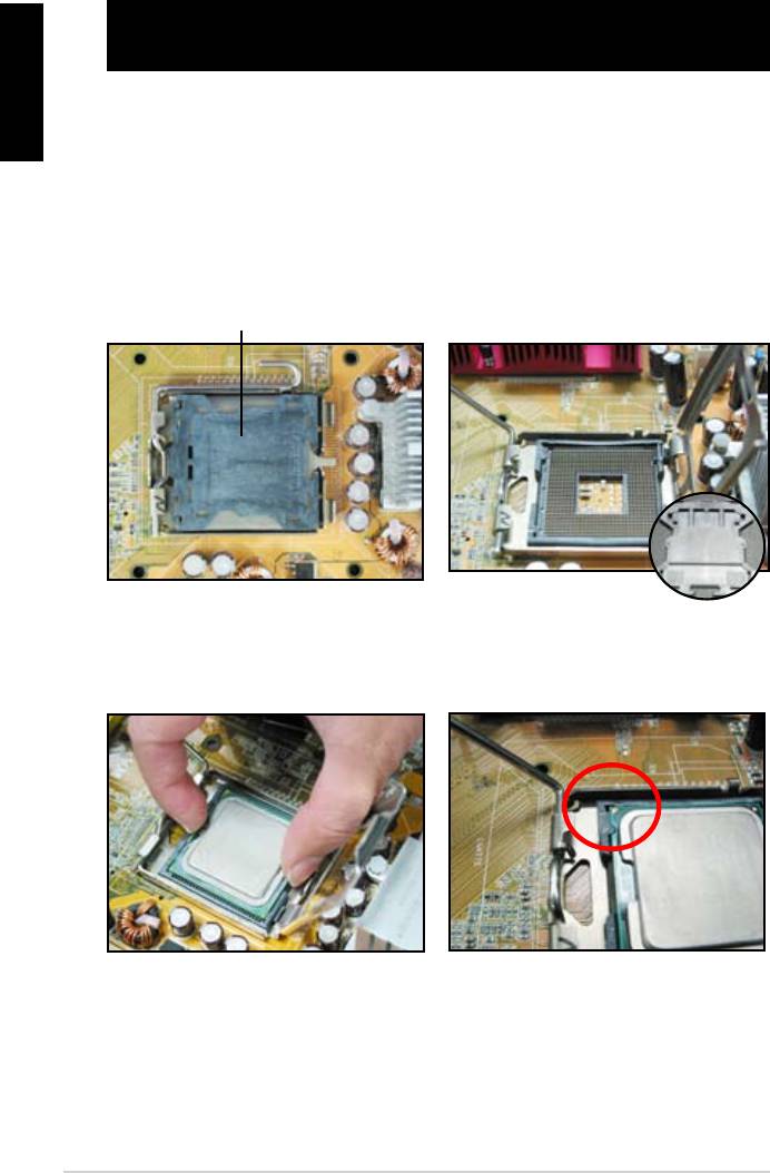
1.1.1 Intel LGA775 Socket
2. Release the load lever from the
motherboard.
retention tab and lift the load plate.
Then push the PnP cap from the
load plate window to remove
To prevent damage to the socket
pins, do not remove the PnP cap
Pick and Place Cap (PnP Cap)
4. Make sure that the gold triangle
3. Position the CPU over the socket.
is on the bottom‑left corner of the
socket.
4
English
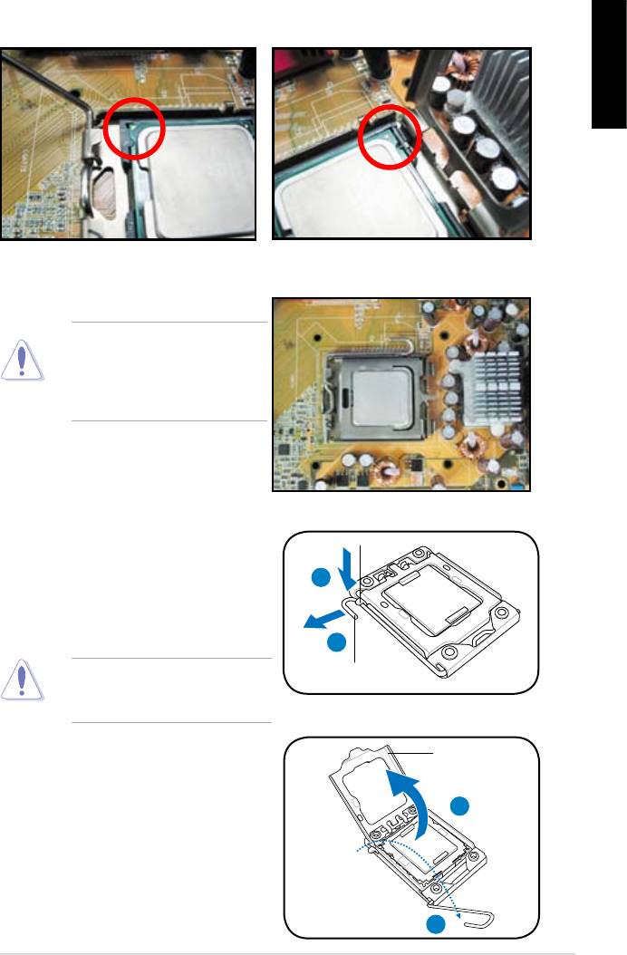
6. Close the load plate, then push the load lever until it snaps into the retention
tab.
CPU into the socket to prevent
bending the connectors on the
socket and damaging the CPU!
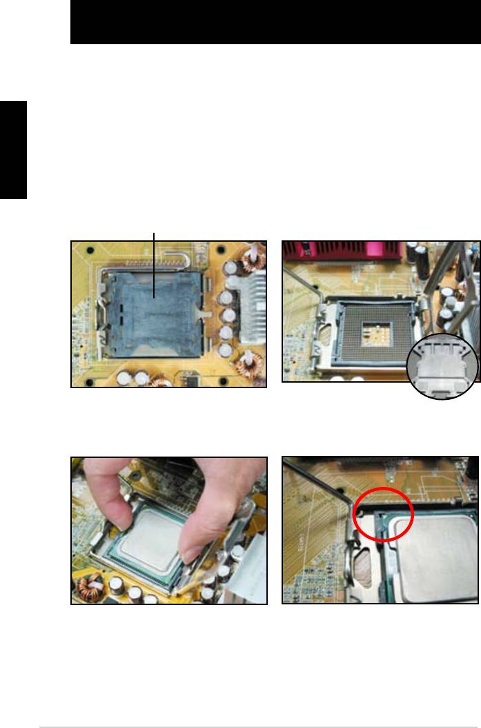
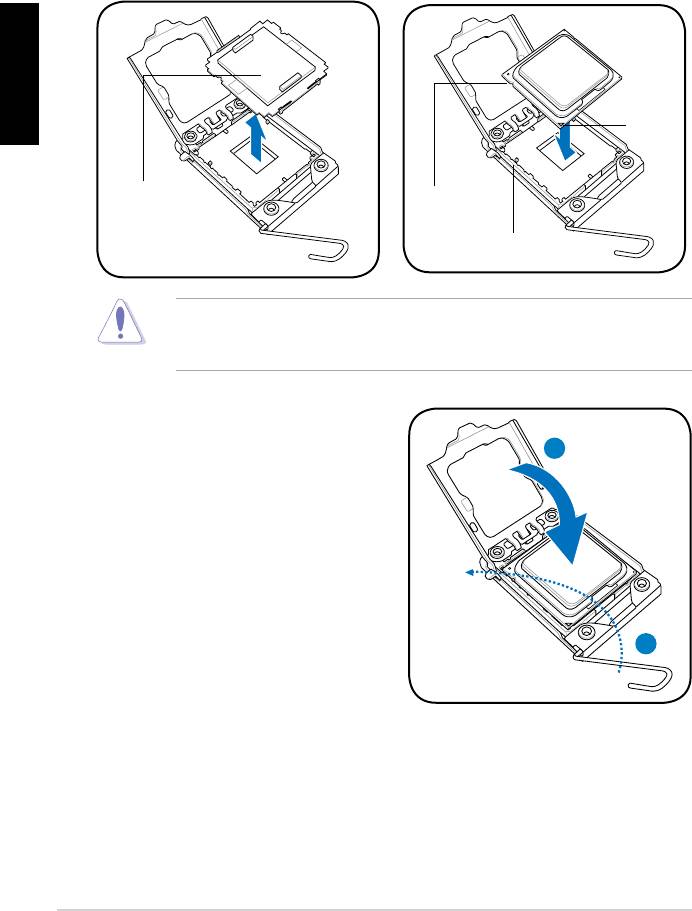
1.1.2 Intel LGA1366 Socket
Retention tab
motherboard.
A
thumb (A), then move it to the left
(B) until it is released from the
retention tab.
B
Load lever
To prevent damage to the socket
pins, do not remove the PnP cap
Load plate
the arrow to a 135º angle.
4
3
ASUS Motherboard installation guide 5
English
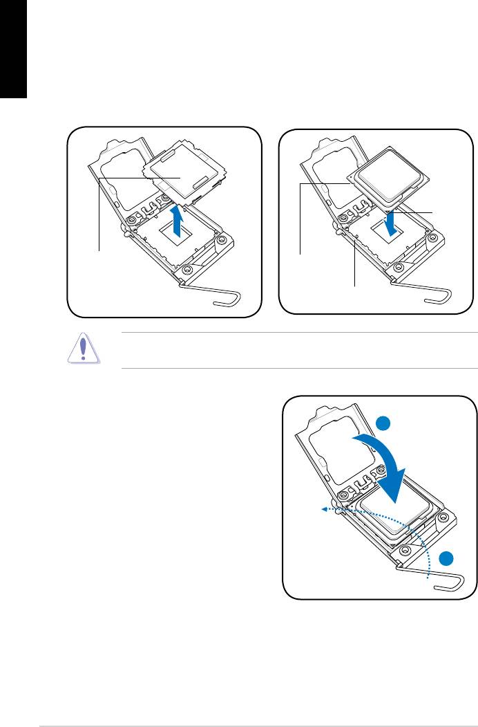
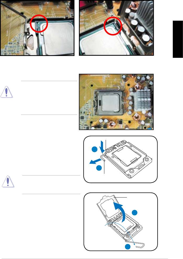
5. Remove the PnP cap from the CPU
6. Position the CPU over the socket,
socket.
making sure that the gold triangle
is on the bottom‑left corner of the
Gold
triangle
mark
PnP cap
CPU notch
Alignment key
socket to prevent bending the connectors on the socket and damaging the CPU!
8. Close the load plate (A), and then
push the load lever (B) until it snaps
A
into the retention tab.
B
6
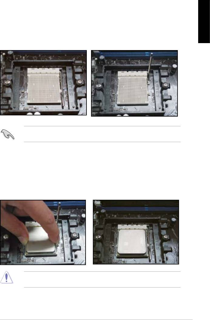
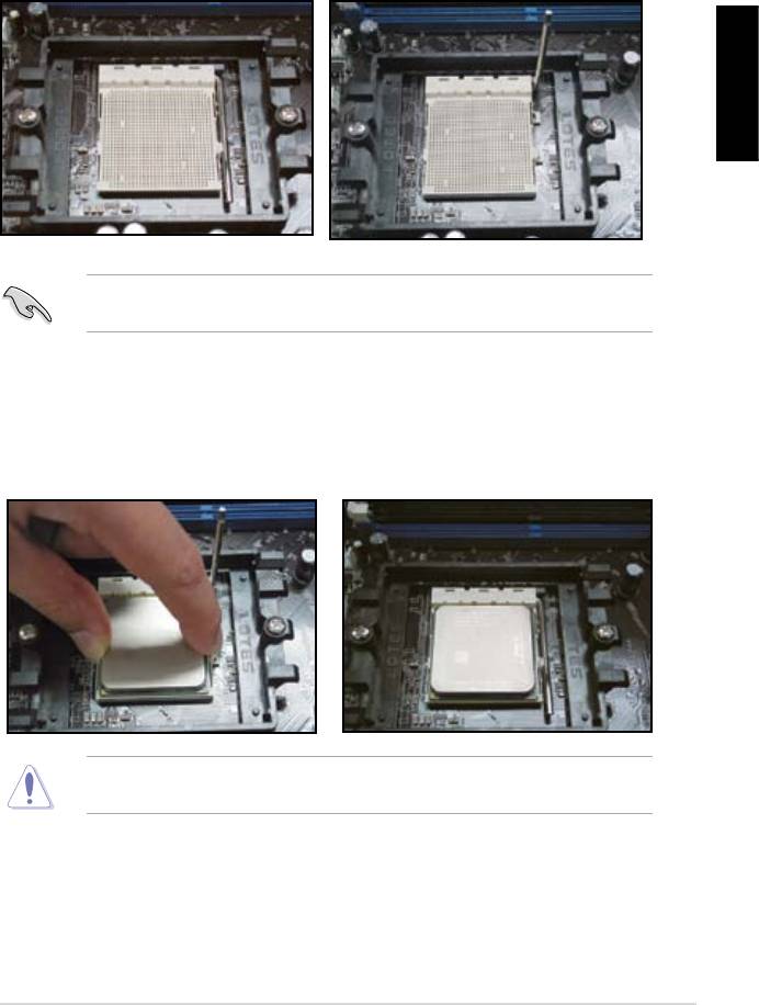
1.1.3 AMD AM2 Socket
English
motherboard.
the socket, then lift it up to a 90º
angle.
Make sure that the socket lever is lifted up to 90º angle. Otherwise, the CPU will
3. Position the CPU above the socket
such that the CPU corner with the
down the socket lever to secure the
gold triangle matches the socket
CPU. The lever clicks on the side tab
corner with a small triangle.
to indicate that it is locked.
socket to prevent bending the connectors on the socket and damaging the CPU!
ASUS Motherboard installation guide 7
English
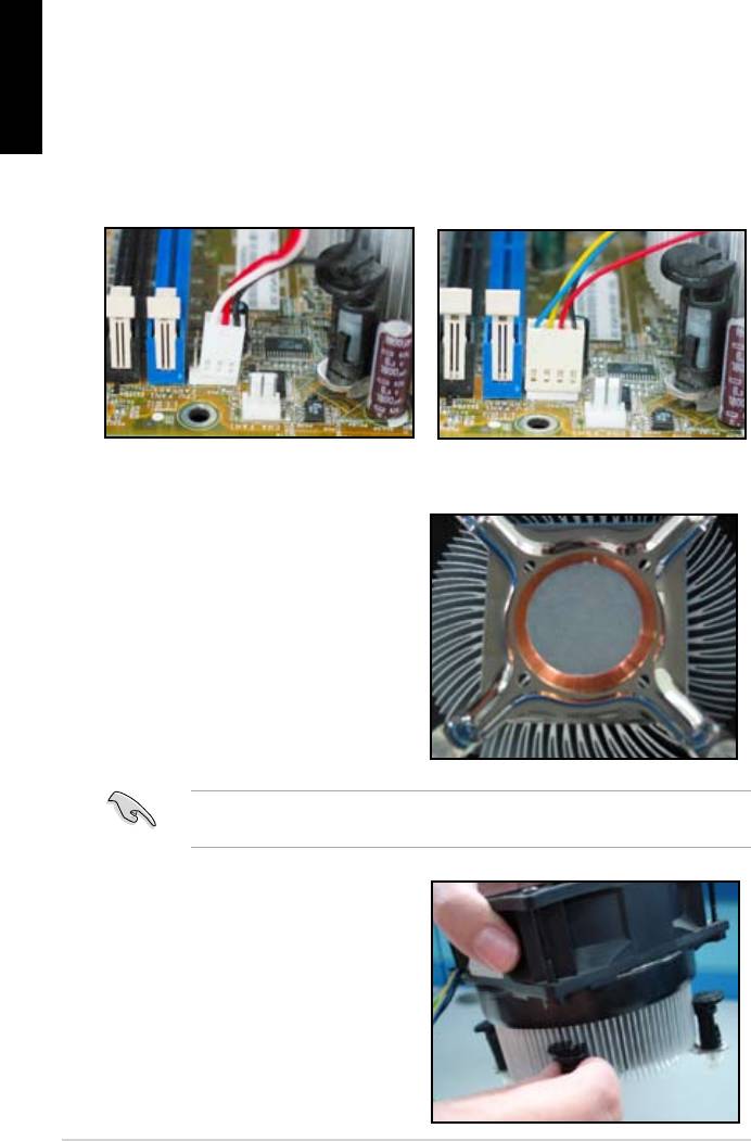
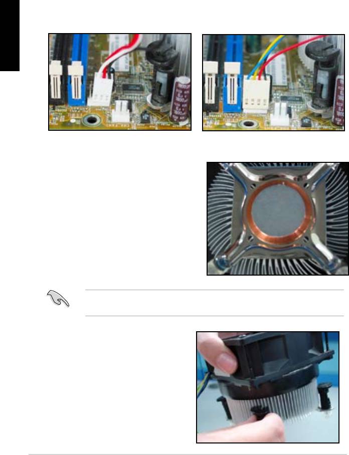
1.2 Installing the heatsink and fan
For Intel-certied heatsink:
2. Some heatsinks will come with
pre‑applied thermal paste. If so,
do not scrape it off and remove
installation. If not, before installing
thermal paste to the exposed area
of the CPU that the heatsink will be
in contact with. Make sure that it is
3. Orient each fastener with the
narrow end of the groove pointing
outward.
8
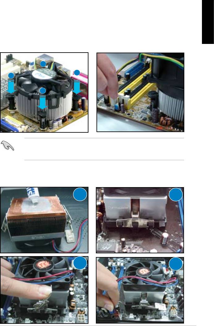
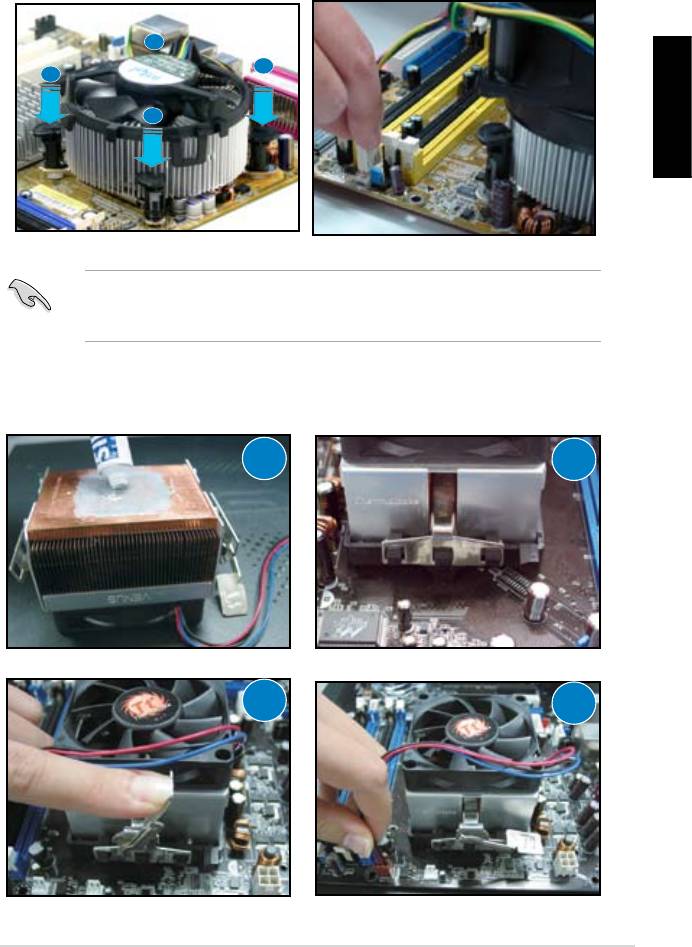
4. Push down two fasteners at a time
5. Connect the CPU fan cable to the
in a diagonal sequence to secure
corresponding connector on the
English
motherboard.
place.
B
A
A
B
directional heatsink to gain the maximum heat dissipation area.
For AMD-certied heatsink:
1
2
3
4
ASUS Motherboard installation guide 9
English
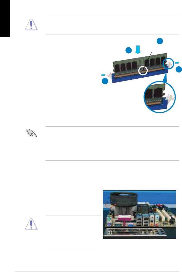
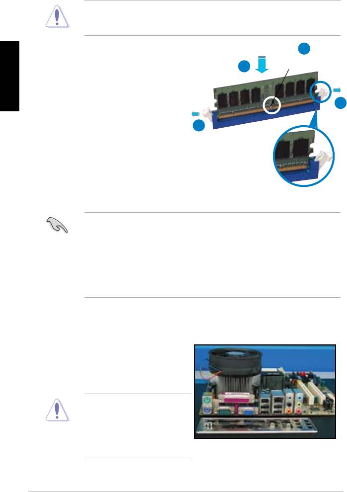
1.3 Installing a DIMM
motherboard and the components.
2
DDR2 DIMM notch
3
1. Press the retaining clips outward
1
matches the break on the socket.
1
socket until the retaining clips
Unlocked retaining clip
motherboard package.
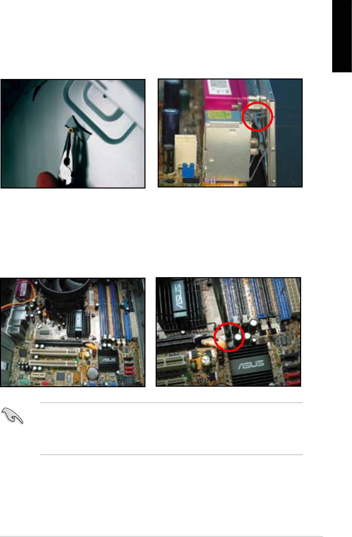
1.4 Installing the motherboard
1. I/O ports differ with motherboards.
Use and install the rear I/O shield
that comes with the motherboard
Some sharp edges and points
puncture resistant gloves before
motherboard and I/O shield
installation.
10
2. Install the standoffs to the matched
screw holes on the metal plate.
damage the I/O ports. Be cautious
English
when installing the I/O shield.
4. Position the I/O side of the
motherboard toward the rear of the
After all the screws have been
chassis and place the motherboard
inserted, drive the screws until
into the chassis.
of the chassis before installing the motherboard. For some chassis models,
ASUS Motherboard installation guide 11
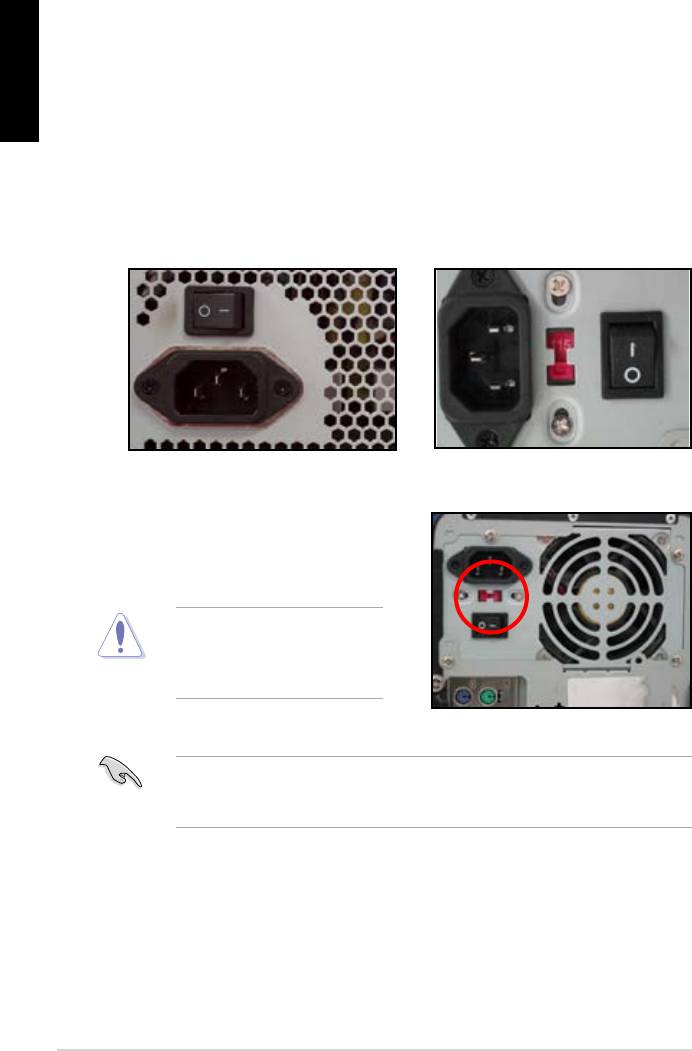
1.5 Installing the power supply unit
English
Power Factor Correction (PFC) and the other with passive PFC.
Power supply with active PFC:
Power supply with passive PFC:
Passive PFC requires user to
the AC input voltage.
voltage.
area.
12
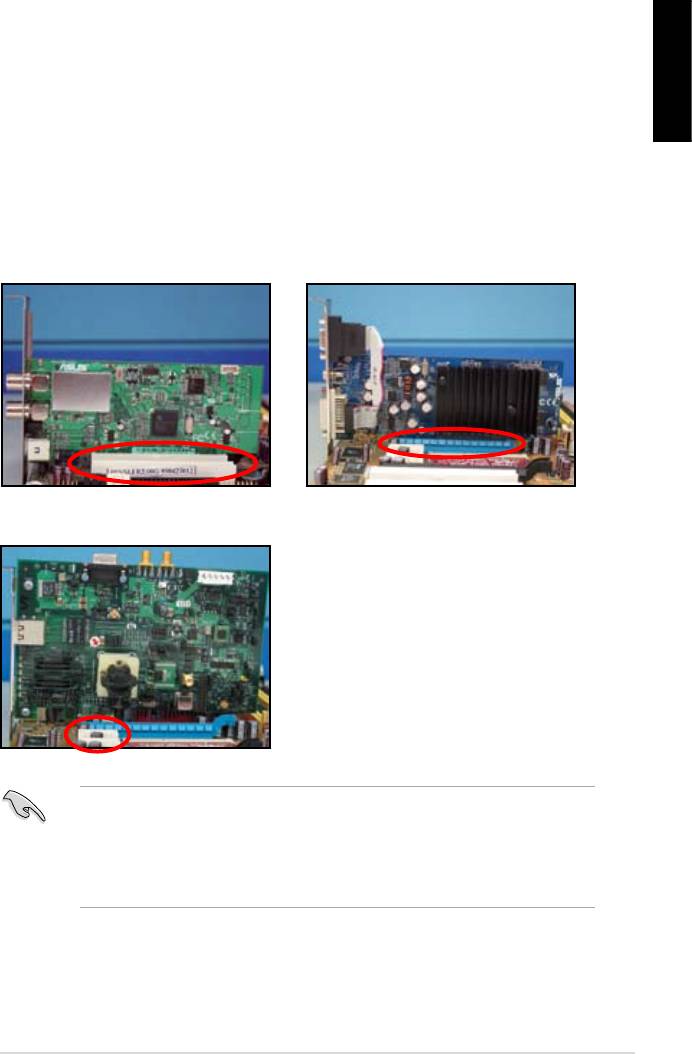
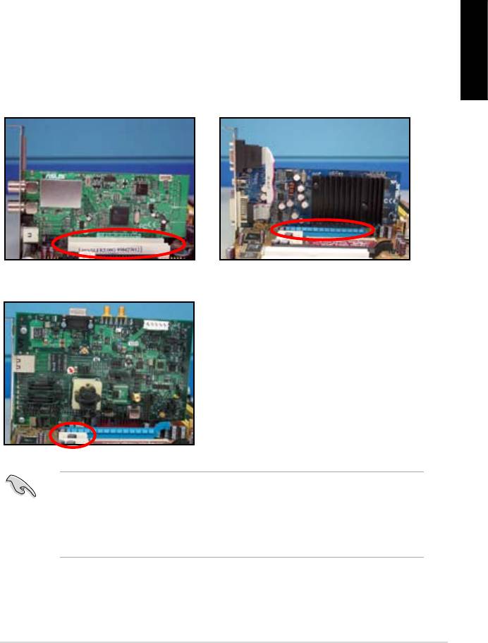
1.6 Installing an expansion card
English
wish to install an expansion card.
3. Screw to secure the card on the slot.
4. Repeat the previous steps to install another expansion card.
PCI card PCIE x16 card
PCIE x1 card
after installing the expansion card.
• Refer to the motherboard user guide for the instructions of the expansion
card signal cable connection.
ASUS Motherboard installation guide 13
1.7 Installing disk drives
English
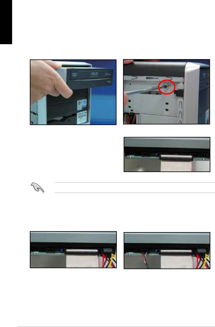
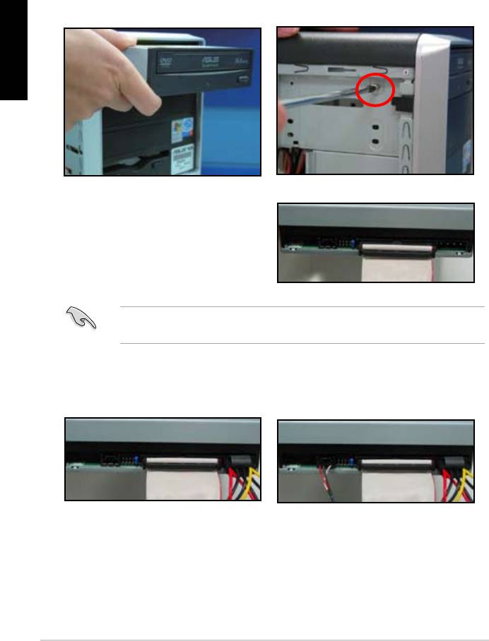
1.7.1 PATA optical disk drive
2. Align with the screw holes and
slide the optical disk drive into the
secure the disk drive with screws.
the optical drive. The red stripe on
should match the dimple marking
Pin1 on the optical drive.
4. Connect the 4‑pin power cable to
5. Attach the audio cable to the
the optical drive.
connector on the optical drive.
14
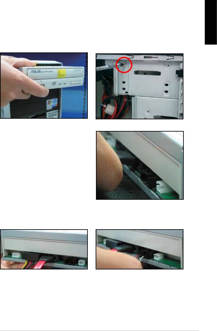
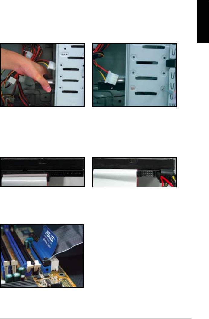
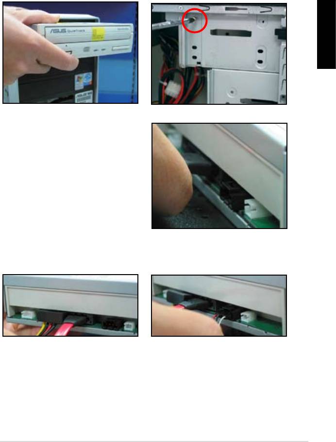
1.7.2 SATA optical disk drive
2. Align with the screw holes and
English
slide the optical disk drive into the
secure the disk drive with screws.
3. Orient and plug the SATA cable into
the optical drive. SATA cables are
cable into the connector.
4. Connect the SATA power cable to
5. Attach the audio cable to the
the the optical drive.
connector on the optical drive.
ASUS Motherboard installation guide 15
English
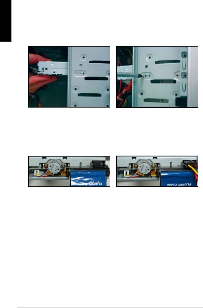
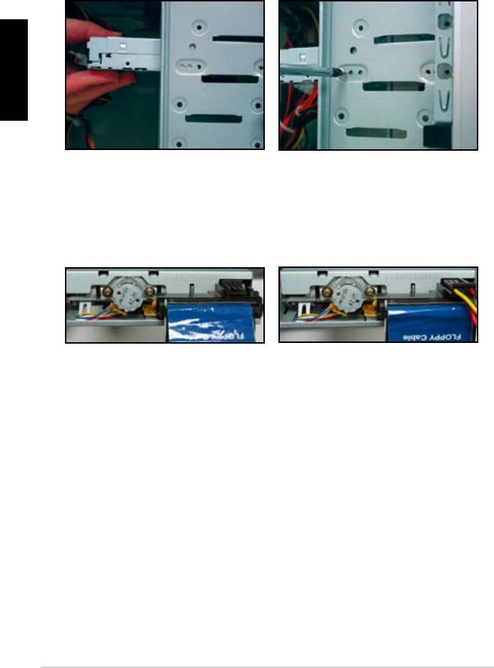
1.7.3 Floppy disk drive
2. Align with the screw holes and
secure the disk drive with screws.
the connector at the back of the
red stripe on the cable is the pin1
end and should match pin1 on the
16
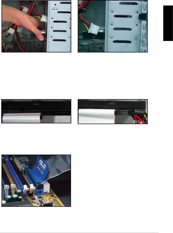
1.7.4 PATA hard disk drive
1. Insert the PATA hard disk drive into
2. Align with the screw holes and
English
secure the disk drive with screws.
3. Orient and connect the signal cable
4. Connect the 4‑pin power cable to
to the hard disk drive. The red stripe
the connector at the back of the
on the cable is the pin1 end. Match
hard disk drive.
force the cable into the connector.
5. Attach the other end of the signal
cable to the corresponding slot on
the motherboard.
ASUS Motherboard installation guide 17
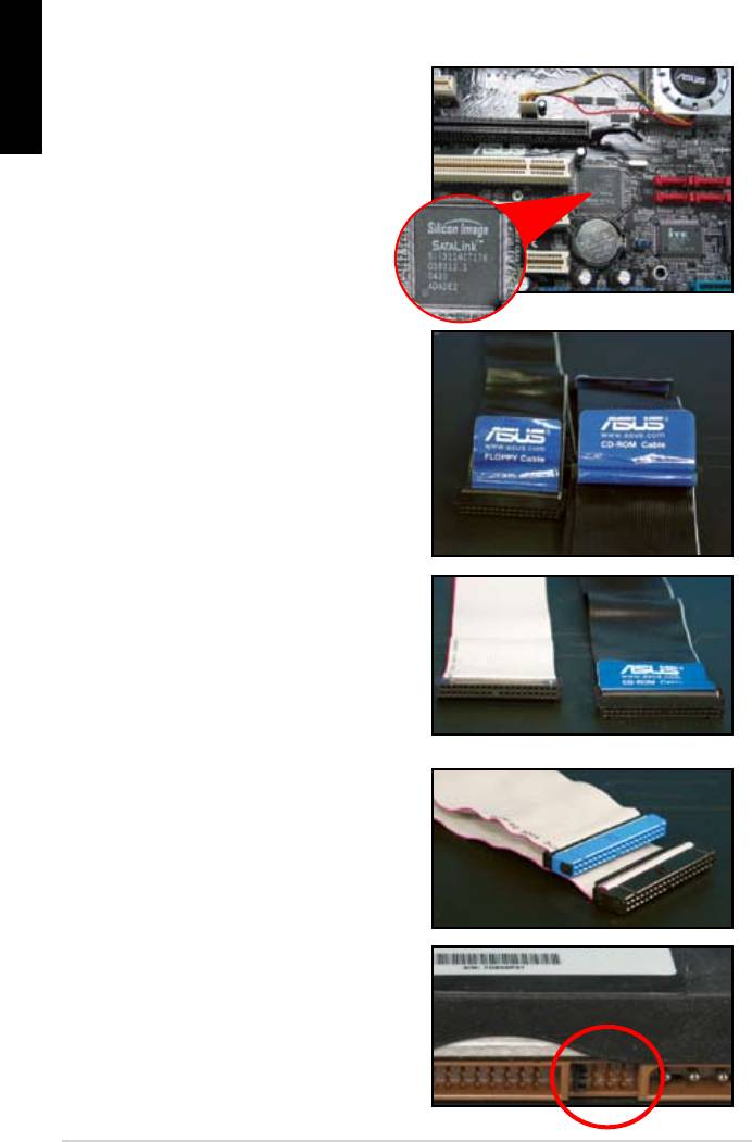
Notes for installing PATA hard disk drive
English
have to install the controller driver
• The cables are designed with pull
drives based on the cable labels.
To prevent damaging the pins, pull
the cable tabs to disconnect the
cable.
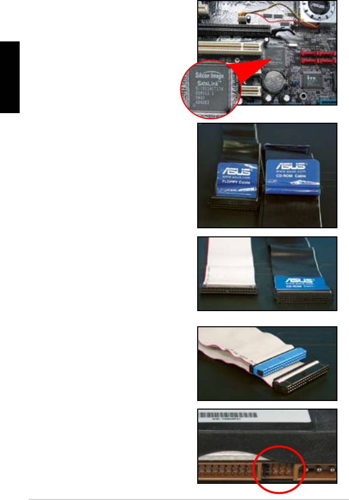
disk drives, the newer 80‑wire
(right) and the older 40‑wire (left)
cables. For ATA66/100/133 disk
offer a better performance. The
optical drives.
• The cable connector is color‑
coded. The blue one is for the host
drive.
different position, one in master
18
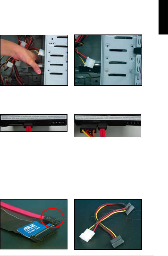
1.7.5 SATA hard disk drive
1. Insert the SATA hard disk drive into
2. Align with the screw holes and
English
secure the disk drive with screws.
3. Orient and connect the SATA cable
4. Connect the SATA power cable to
to the hard disk drive. The cable can
the connector at the back of the
hard disk drive.
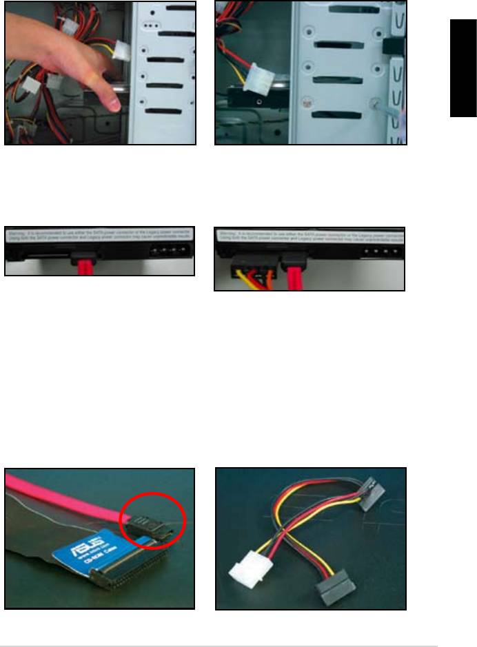
Notes for installing SATA hard disk drive
• Serial ATA (SATA) interface
• The SATA power cable connector
provides higher data transmission
is different from the traditional
speed, and better voltage tolerance.
4‑pin power connector. ASUS
The narrow design of the SATA
motherboard bundles power adapter
cable also solves cabling issues
chassis.
new connector.
ASUS Motherboard installation guide 19
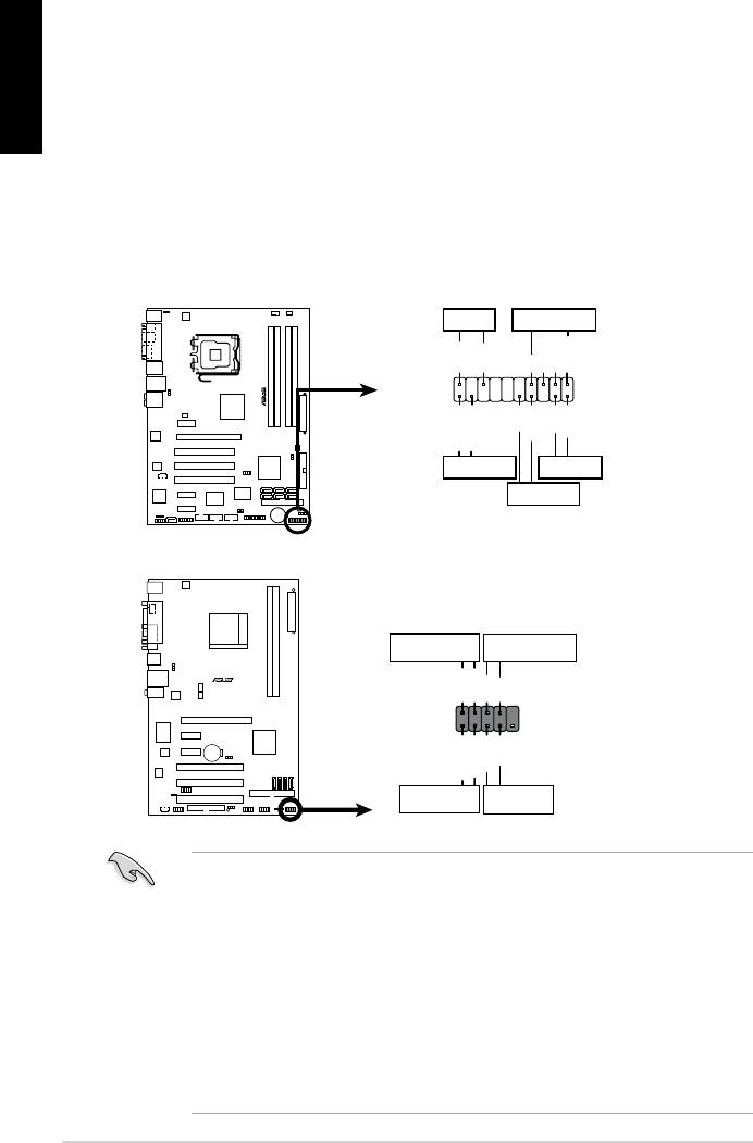
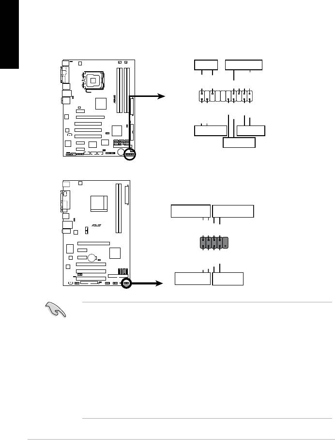
1.8 Front panel cables
English
• RESET (Reset Switch)
• SPEAKER (Speaker Connector)
20
M2N-X
Reset
ANE
RESET
PLED SPEAKER
P5B-E
PLED+
PLED-
+5V
Ground
Ground
Speaker
®
PANEL
PWR
Reset
Ground
Ground
IDE_LED+
IDE_LED-
IDE_LED
RESET
PWRSW
*
Requires an ATX power supply.
20-8 pin front panel connector
PIN1
PIN1
10-1 pin front panel connector
Connect these connectors to the motherboard according to the label.
for the ground pins and the color‑coded wire for the signal pins.
to the connector PIN1 on the motherboard.
user guide for more information.
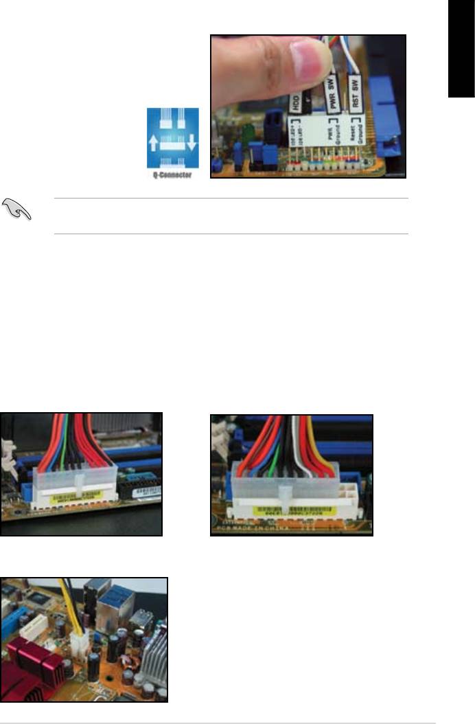
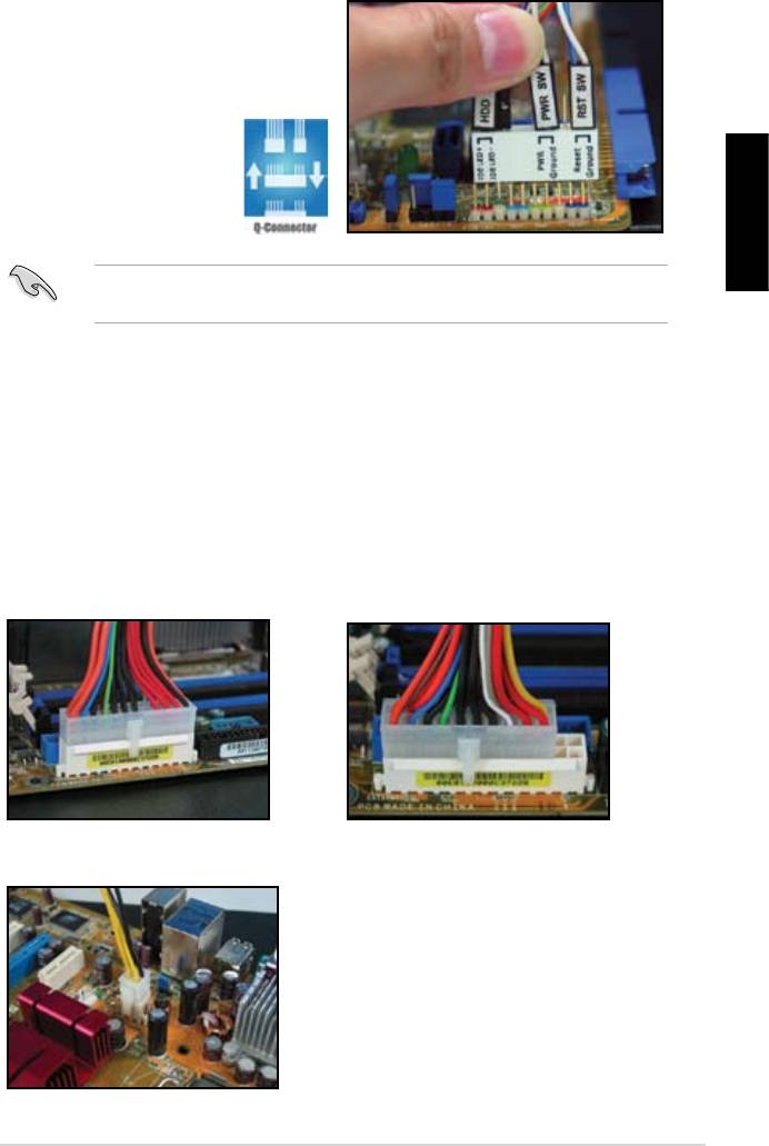
ASUS Q-Connector
English
user guide for details.
details.
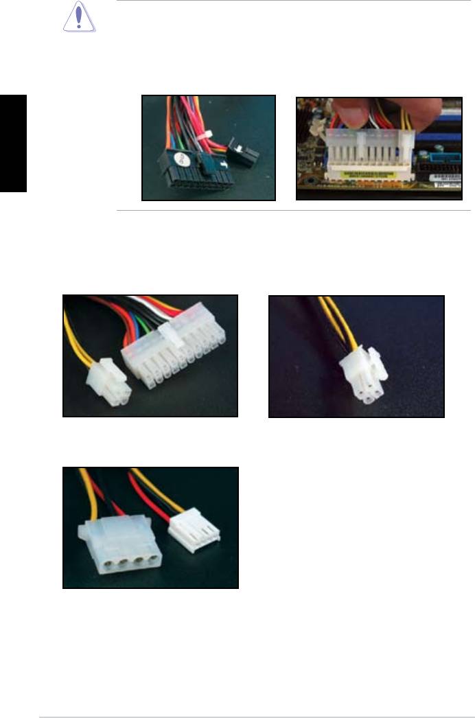
1.9 Connecting the ATX power
connector on the motherboard.
20-pin power connector
24-pin power connector
(on the 24-pin female counterpart)
4-pin power connector
ASUS Motherboard installation guide 21
English
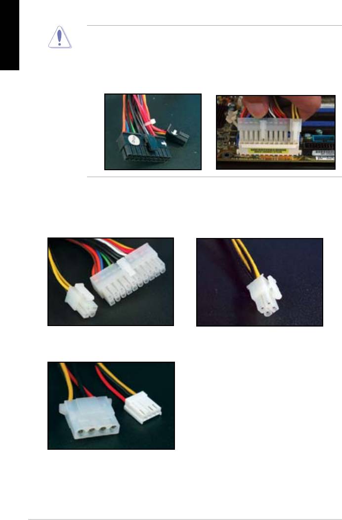
connectors to the motherboard.
two connectors and install to the 24‑pin connectors on the motherboard.
Power connectors
20+4 (24) pin ATX connector
4-pin ATX connector
peripheral power connector (left)
oppy power connector (right)
22
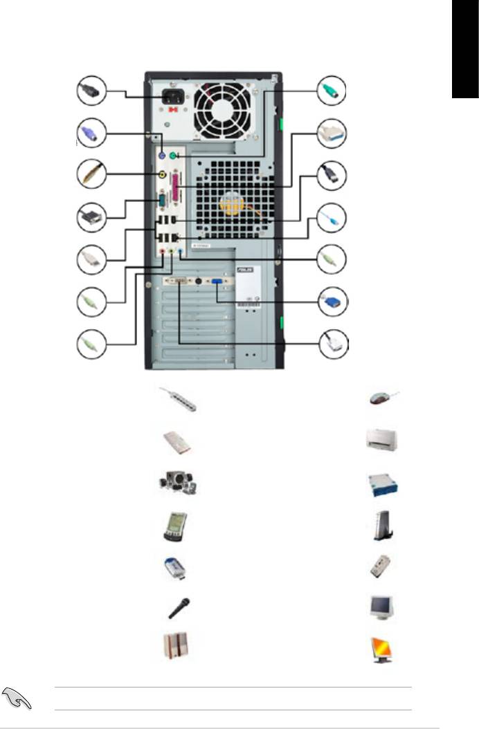
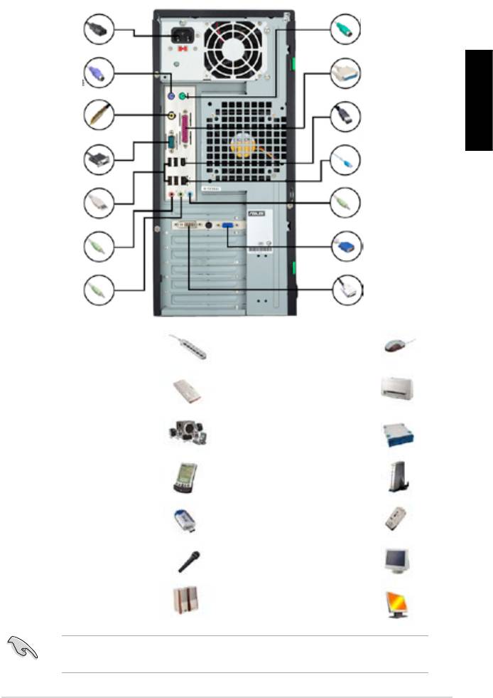
1.10 Peripheral devices and accessories
English
1. AC power plug
8. PS/2
mouse port
2. PS/2 keyboard
9. Parallel port
port
3. S/PDIF out port
10. IEEE1394 port
4. Serial port
11. LAN (RJ45) port
5. USB port
12. Line in port
13. Video graphics
6. Microphone port
adapter port
7. Line out port 14. DVI port
extension cord
mouse
hard disk drive
microphone
ASUS Motherboard installation guide 23
1.11 Startingupforthersttime
English
the BIOS beeps.
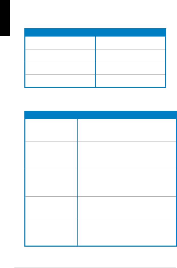
BIOS Beep Description
short beeps
short beeps then a pause (repeated)
short beeps
(AMI BIOS)
Four short beeps
Troubleshooting
Trouble Action
• Cannot turn on the computer
working.
The computer is on but the
monitor is black.
• Shut down the computer and remove the power cord.
socket.
a warning message pops on
the screen.)
drive.
• Make sure the device drivers are installed.
24

Chapter 2: Manage/update BIOS
2.1 AFUDOS utility
English
corrupted during the updating process.
Copying the current BIOS
afudos /o[lename]
characters for the extension name.
A:\>afudos /oOLDBIOS1.rom
Main lename Extension name
A:\>afudos /oOLDBIOS1.rom
AMI Firmware Update Utility — Version 1.19(ASUS V2.07(03.11.24BB))
Copyright (C) 2002 American Megatrends, Inc. All rights reserved.
Reading ash ….. done
Write to le…… ok
A:\>
Updating the BIOS le
ASUS Motherboard installation guide 25

English
afudos /i[lename]
disk.
A:\>afudos /iP5K3D.ROM
A:\>afudos /iP5K3D.ROM
AMI Firmware Update Utility — Version 1.19(ASUS V2.07(03.11.24BB))
Copyright (C) 2002 American Megatrends, Inc. All rights reserved.
WARNING!! Do not turn off power during ash BIOS
Reading le ……. done
Reading ash …… done
Advance Check ……
Erasing ash …… done
Writing ash …… 0x0008CC00 (9%)
A:\>afudos /iP5K3D.ROM
AMI Firmware Update Utility — Version 1.19(ASUS V2.07(03.11.24BB))
Copyright (C) 2002 American Megatrends, Inc. All rights reserved.
WARNING!! Do not turn off power during ash BIOS
Reading le ……. done
Reading ash …… done
Advance Check ……
Erasing ash …… done
Writing ash …… done
Verifying ash …. done
Please restart your computer
A:\>
26 Manage/update BIOS
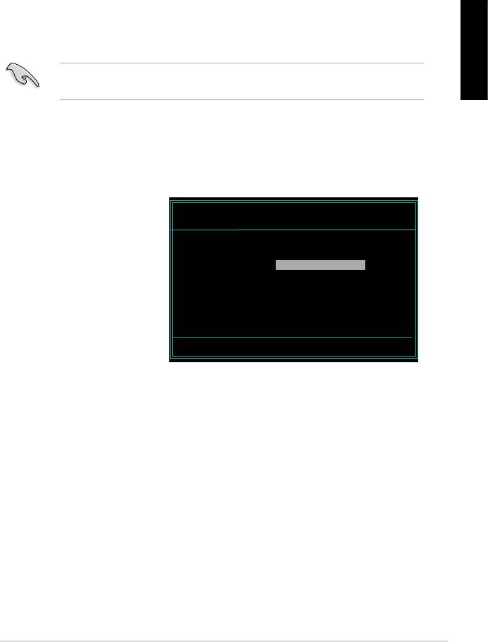
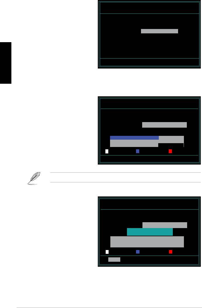
2.2 Award BIOS Flash Utility
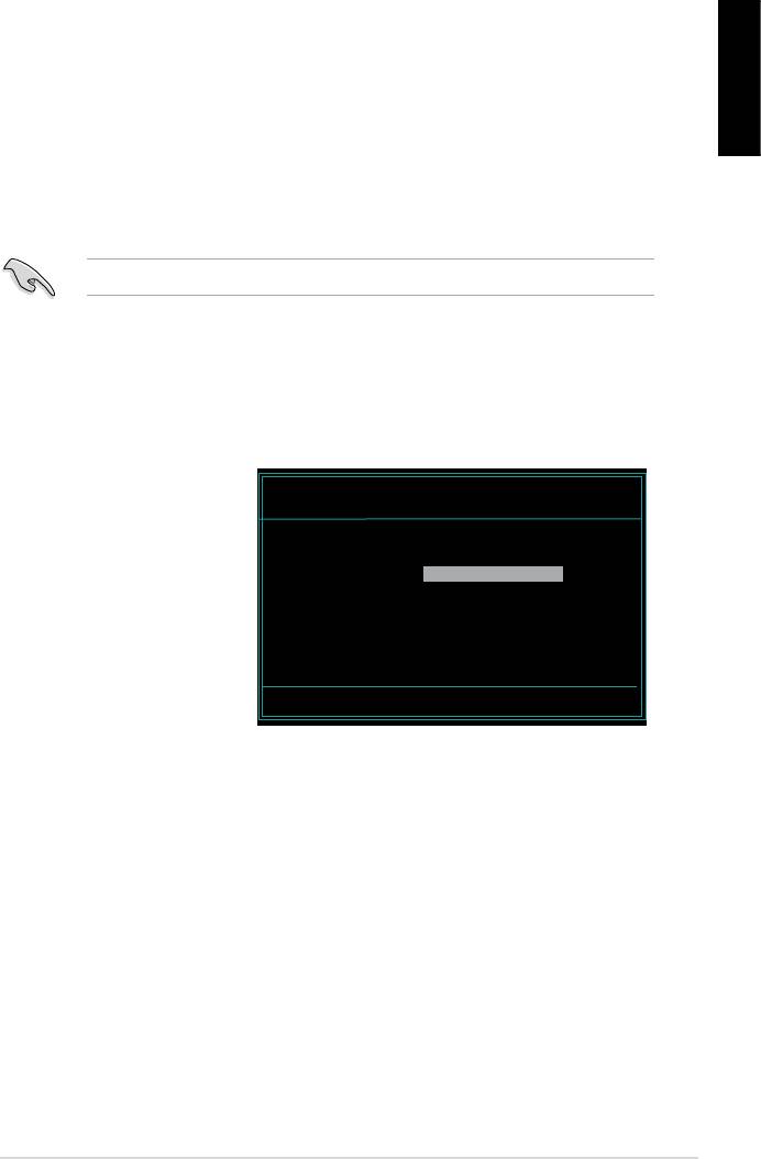
Updating the BIOS
English
FAT 16/12 format.
AwardBIOS Flash Utility for ASUS V1.14
(C) Phoenix Technologies Ltd. All Rights Reserved
the name of the disk
For NF590-SLI-M2N32-SLI-DELUXE DATE:03/30/2006
Flash Type — PMC Pm49FL004T LPC/FWH
assignment) to switch to
File Name to Program:
Message: Please input File Name!
<Enter>. The Award BIOS
ASUS Motherboard installation guide 27
English
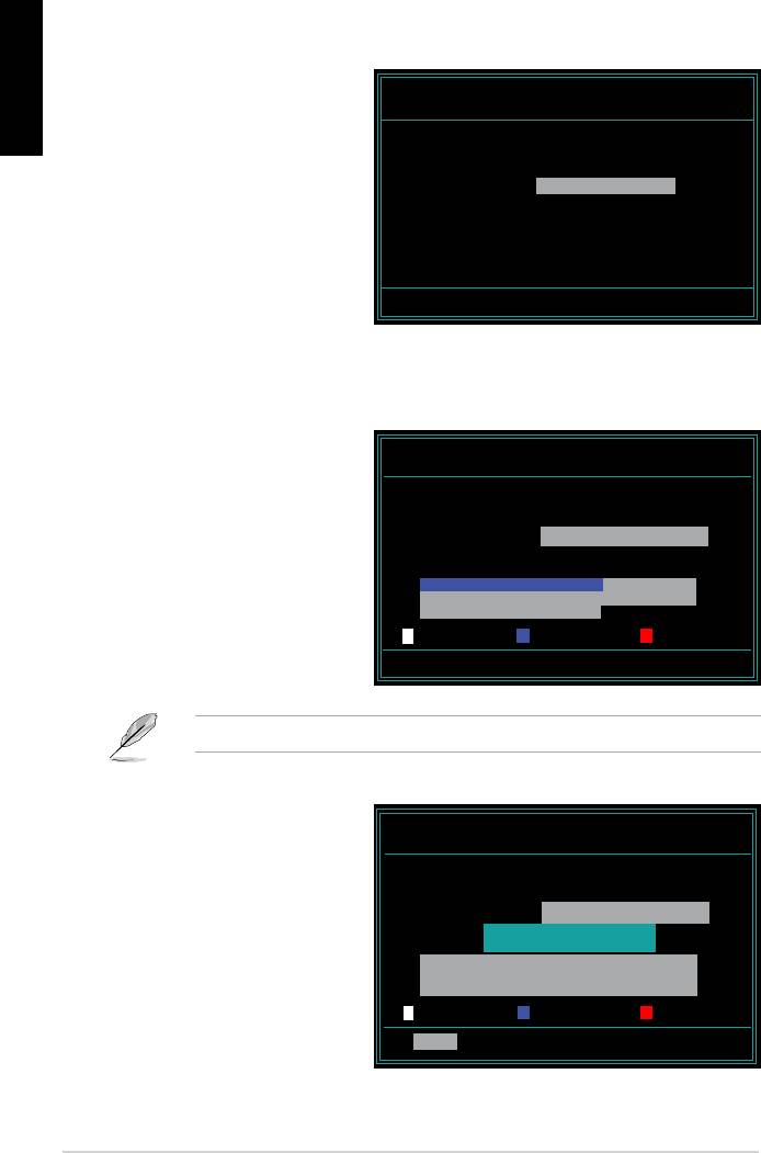
AwardBIOS Flash Utility for ASUS V1.14
the File Name to Program
(C) Phoenix Technologies Ltd. All Rights Reserved
For NF590-SLI-M2N32-SLI-DELUXE DATE:03/30/2006
Flash Type — PMC Pm49FL004T LPC/FWH
File Name to Program: M2N32SLI.bin
Message: Do You Want To Save Bios (Y/N)
following screen appears.
AwardBIOS Flash Utility for ASUS V1.14
(C) Phoenix Technologies Ltd. All Rights Reserved
For NF590-SLI-M2N32-SLI-DELUXE DATE:03/30/2006
Flash Type — PMC Pm49FL004T LPC/FWH
File Name to Program: M2N32SLI.bin
Programming Flash Memory — OFE00 OK
Write OK No Update Write Fail
Warning: Don’t Turn Off Power Or Reset System!
AwardBIOS Flash Utility for ASUS V1.14
Flashing Complete
(C) Phoenix Technologies Ltd. All Rights Reserved
message indicating that
For NF590-SLI-M2N32-SLI-DELUXE DATE:03/30/2006
Flash Type — PMC Pm49FL004T LPC/FWH
File Name to Program: M2N32SLI.bin
Flashing Complete
Remove the disk then
Press <F1> to Continue
press <F1> to restart the
Write OK No Update Write Fail
F1
Reset
28 Manage/update BIOS
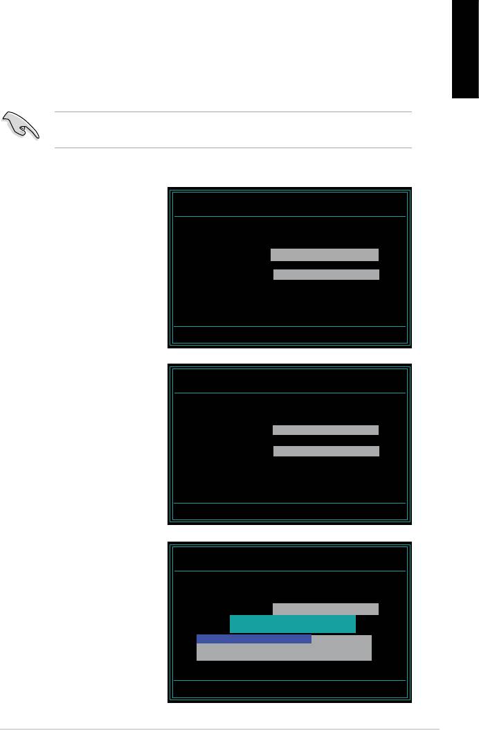
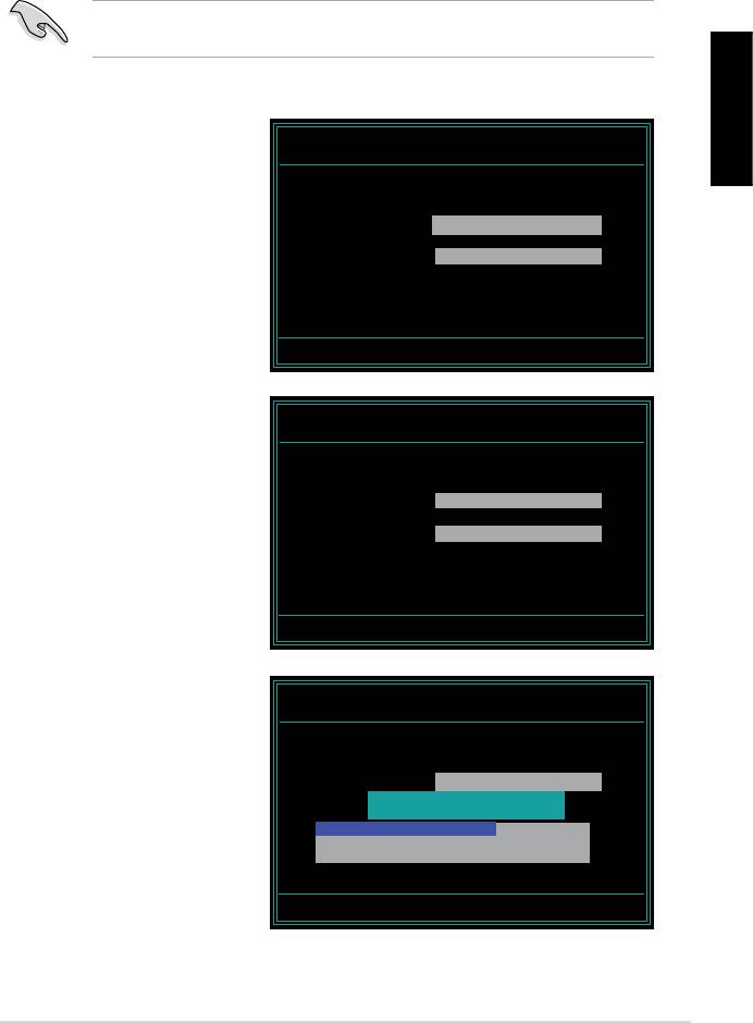
Saving the current BIOS le
English
process.
1. Follow steps 1 to 6 of the
AwardBIOS Flash Utility for ASUS V1.14
(C) Phoenix Technologies Ltd. All Rights Reserved
previous section.
For NF590-SLI-M2N32-SLI-DELUXE DATE:03/30/2006
Flash Type — PMC Pm49FL004T LPC/FWH
File Name to Program: 0112.bin
following screen appears.
Save current BIOS as:
Message:
AwardBIOS Flash Utility for ASUS V1.14
(C) Phoenix Technologies Ltd. All Rights Reserved
For NF590-SLI-M2N32-SLI-DELUXE DATE:03/30/2006
Flash Type — PMC Pm49FL004T LPC/FWH
then press <Enter>.
File Name to Program: 0112.bin
Checksum: 810DH
Save current BIOS as: 0113.bin
Message: Please Wait!
AwardBIOS Flash Utility for ASUS V1.14
(C) Phoenix Technologies Ltd. All Rights Reserved
disk, then returns to the
For NF590-SLI-M2N32-SLI-DELUXE DATE:03/30/2006
Flash Type — PMC Pm49FL004T LPC/FWH
File Name to Program: 0113.bin
Now Backup System BIOS to
File!
Message: Please Wait!
ASUS Motherboard installation guide 29

2.3 ASUS Update utility
English
®
package.
ASUS Update requires an Internet connection either through a network or an
Internet Service Provider (ISP).
Installing ASUS Update
30 Manage/update BIOS
®
English
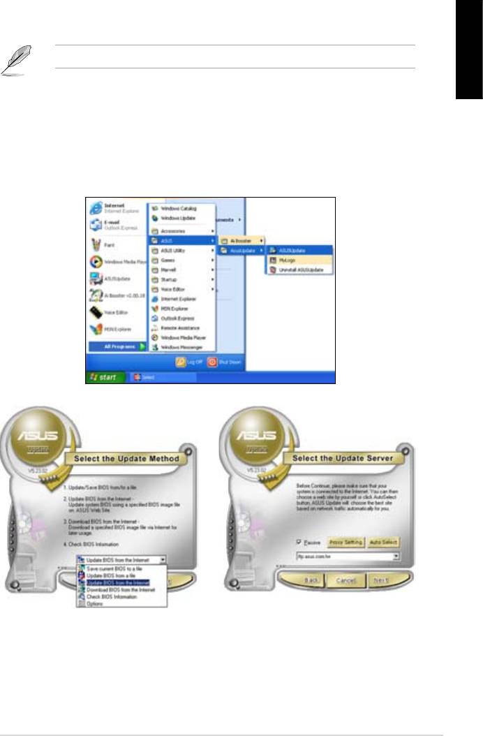
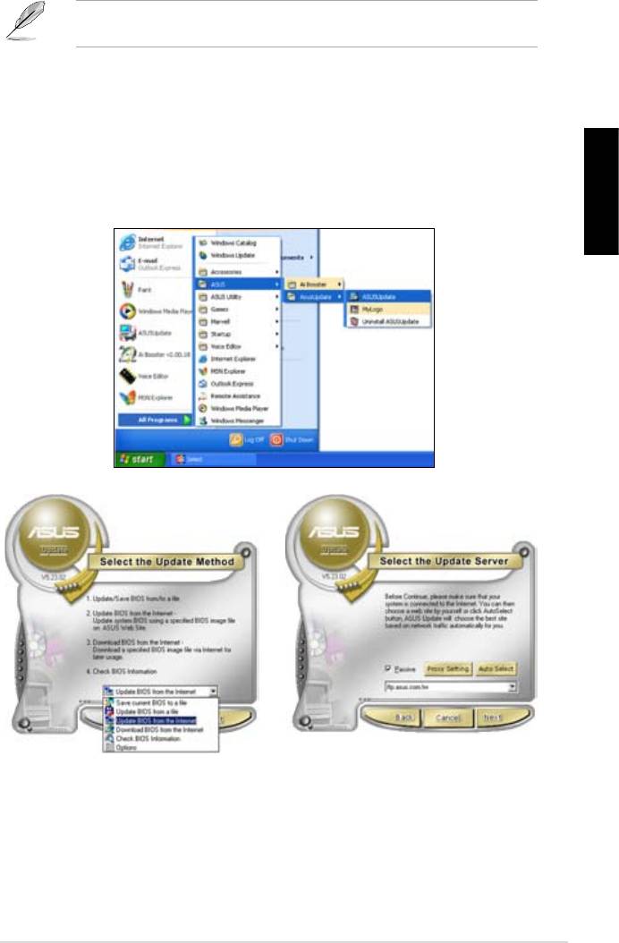
Updating the BIOS through the Internet
®
desktop, click Start >
Programs > ASUS > ASUSUpdate > ASUSUpdate. The ASUS Update main
window appears.
2. Select Update BIOS from the
3. Select the ASUS FTP site nearest
drop‑down menu list, then click
Next.
click Auto Select. Click Next.
ASUS Motherboard installation guide 31
English
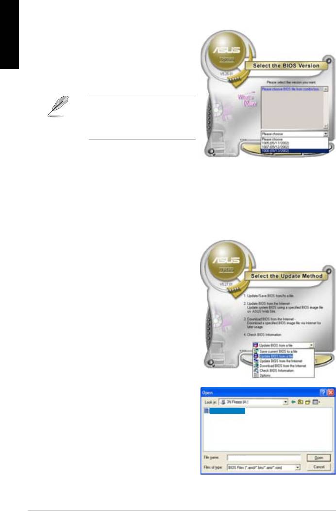
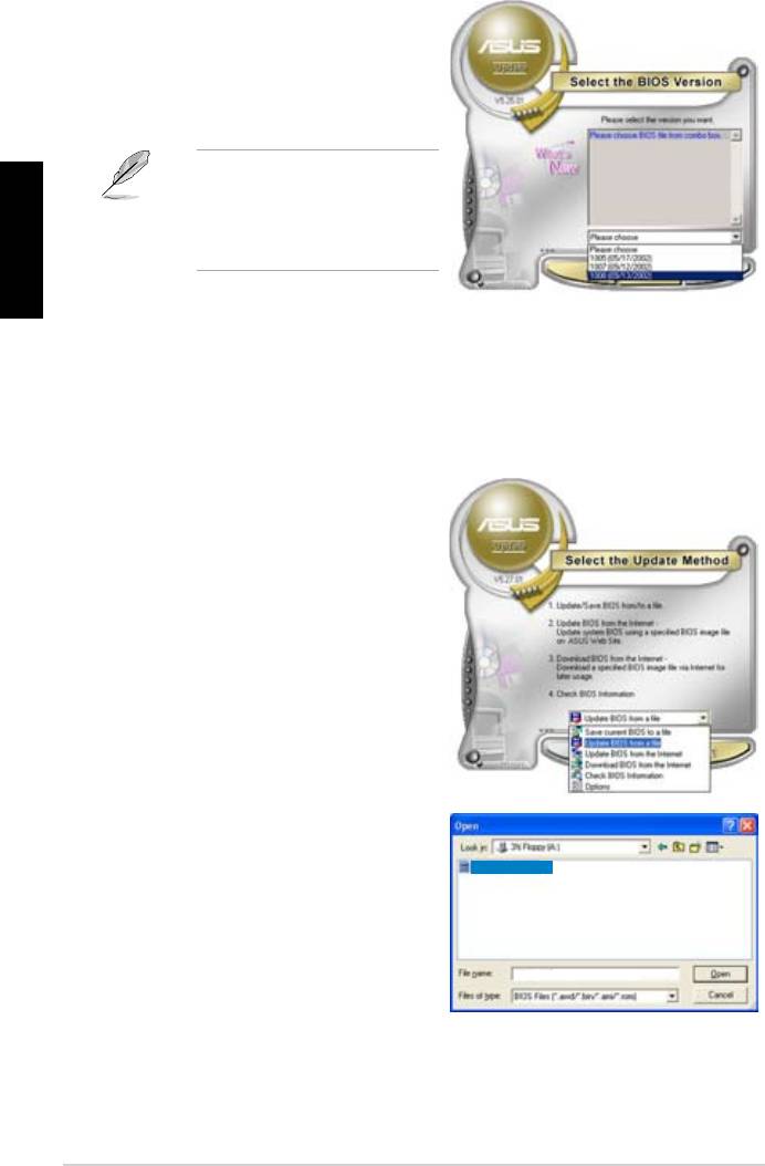
4. From the FTP site, select the BIOS
Click Next.
5. Follow the screen instructions to
complete the update process.
capable of updating itself through
Updating the BIOS through a BIOS le
®
desktop, click Start
> Programs > ASUS > ASUSUpdate > ASUSUpdate. The ASUS Update
main window appears.
2. Select
Update BIOS from the
drop‑down menu list, then click Next.
window, then click Open.
P5K3 Deluxe
4. Follow the screen instructions to
complete the update process.
P5K3 Deluxe
32 Manage/update BIOS
Chapter 3: Troubleshooting
3.1 Troubleshooting for Motherboard DIY
English
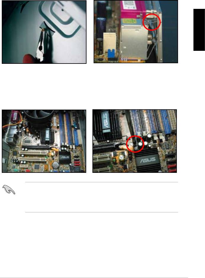
3.1.1 Basic troubleshooting
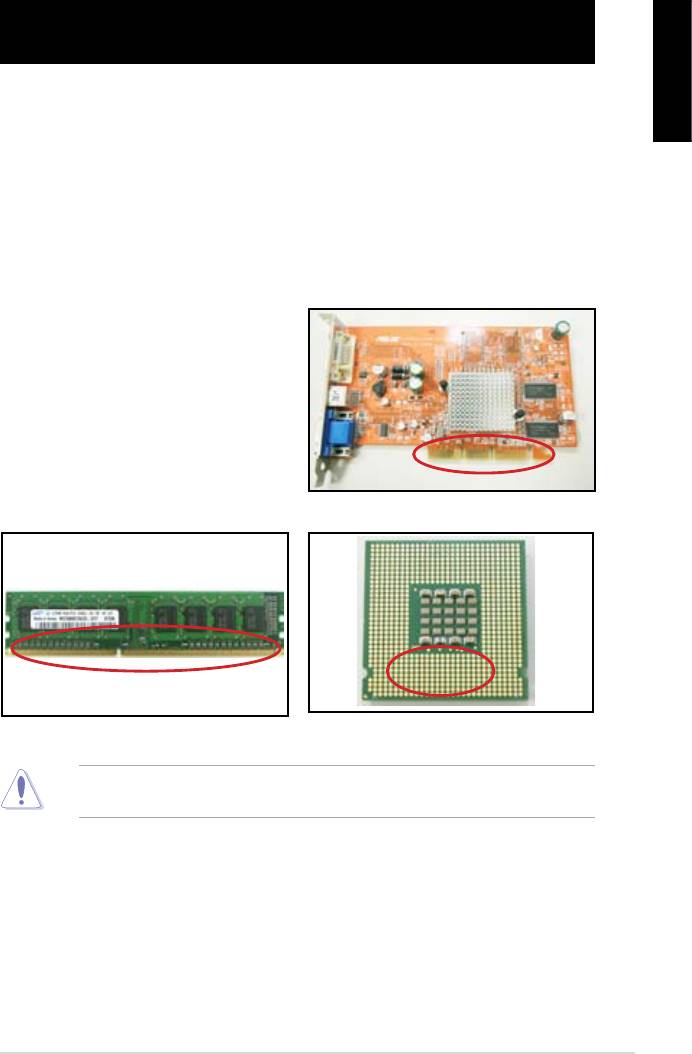
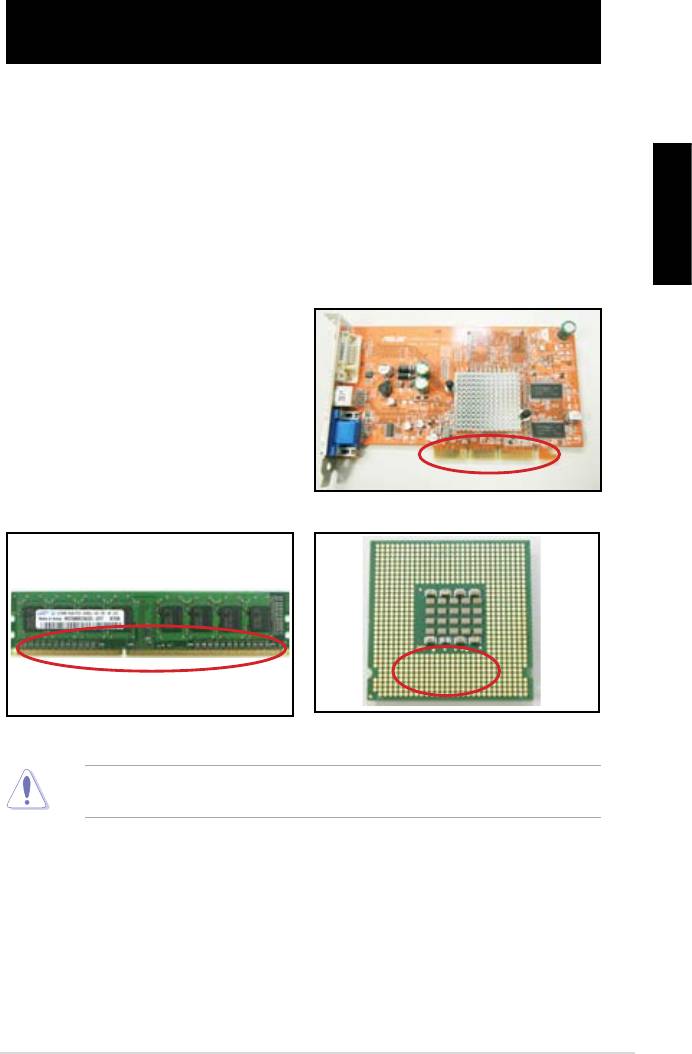
A. Bad connection
1. Make sure there is no contaminants
on the gold contact or the pins.
2. Use a cotton bud or an eraser
crumbs.
VGA card gold contact
DIMM gold contact
LGA775 processor gold contact points
ASUS Motherboard installation guide 33
English
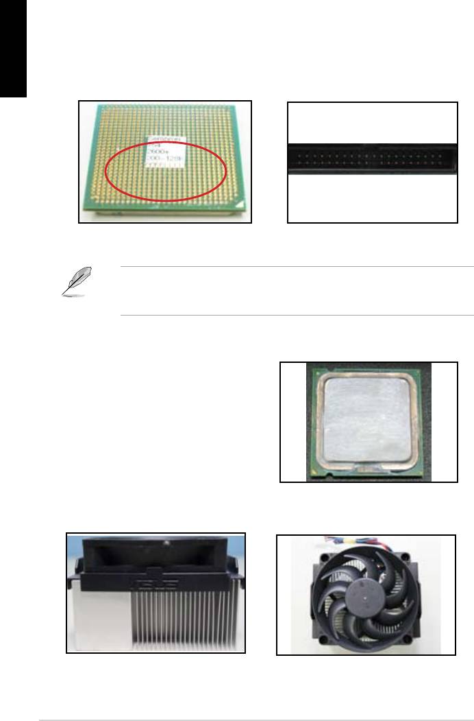
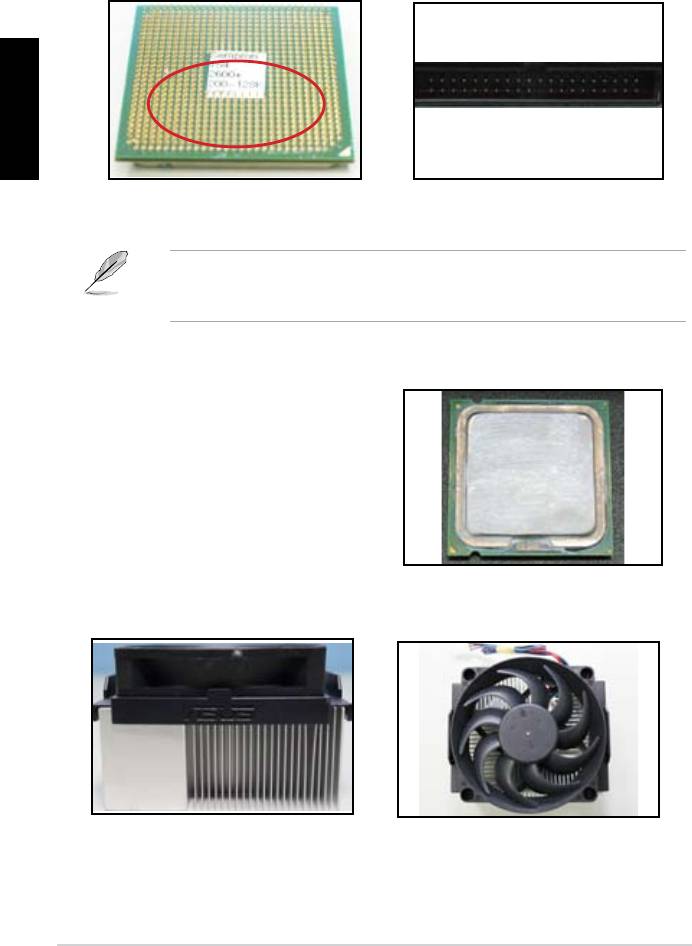
CPU pins. A broken and bended pin will cause the component malfunction.
AMD CPU gold pins
Connector pins
B. CPU overheated
thermal paste to the exposed area
of the CPU that the heatsink will be
in contact with. Make sure that it is
CPU surface
2. Make sure there is no contaminants on the heatsink and fan.
Side view of heatsink and fan
Top view of heatsink and fan
3. Follow the instructions of heatsink and fan manufacturers to clean the
contaminants that will slow down the fan rotation.
34 Troubleshooting
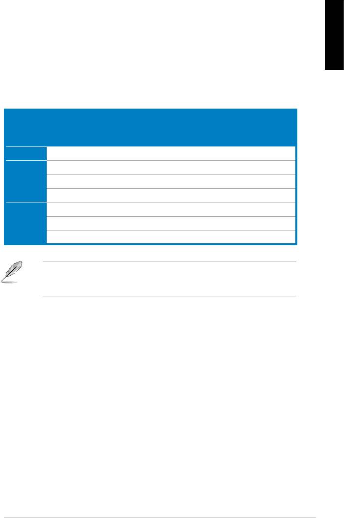
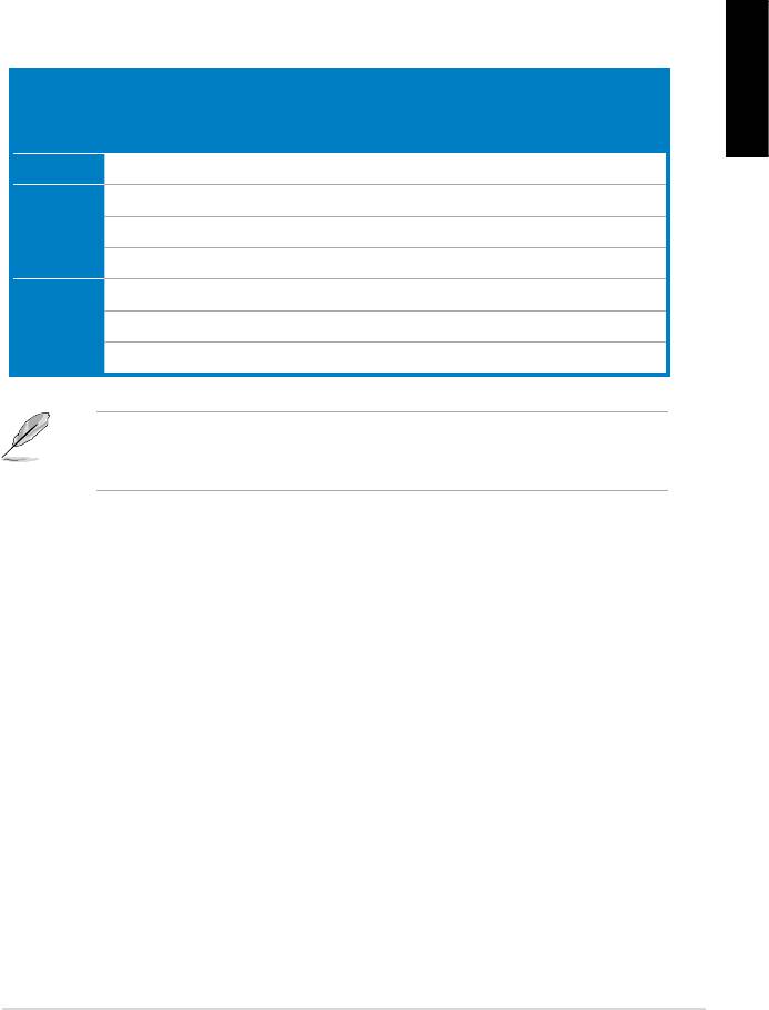
3.2 Other common troubles
unplugged.
English
Test (POST).
• If there are BIOS beeps, refer to section 1.11 for details.
Check Items
Power
Screen
Heatsink
BIOS
Error
Reference
LED
display
and fan
beeps
messages
page
No power Off No Stop No N/A 3‑4
No
On No Stop No N/A 3‑5
screen
On No Running No N/A 3‑5
display
On No Running N//A 3‑5
Failure to
On Running 3‑5
enter OS
On Running No 3‑5
On Running No No 3‑5
team for further help.
ASUS Motherboard installation guide 35
English
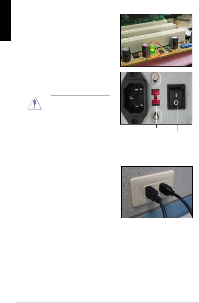
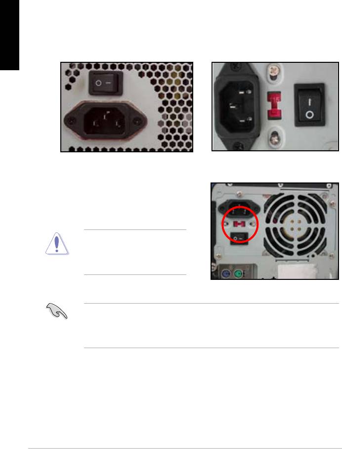
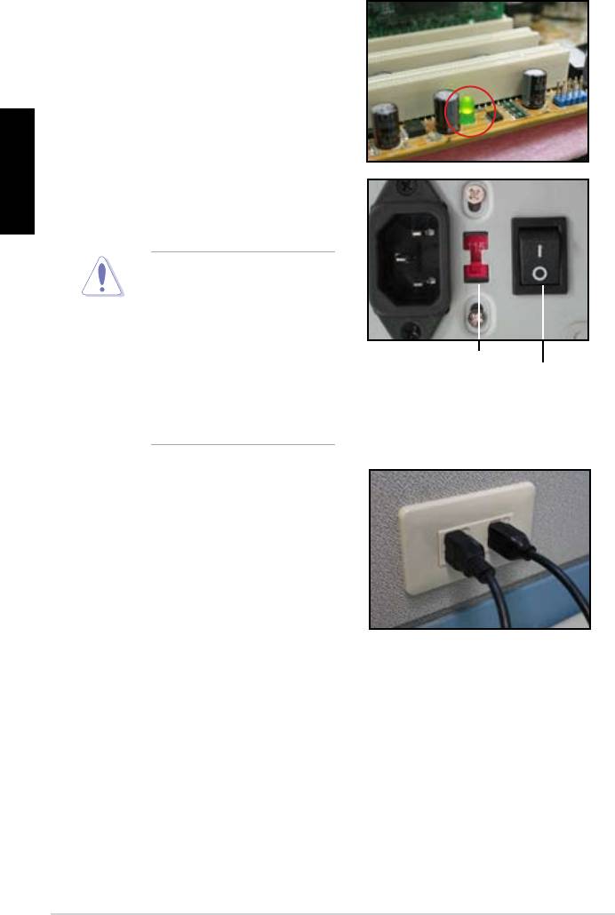
3.2.1 No power
the problem.
input voltage, ensure to
disconnect the power
plug. Failure to do so will
AC input voltage switch
Power switch
“—”: On; “O”: Off
power cord to the wall outlet.
• Connect the power plug
NOT connect it to the power
extension, uninterruptible
devices.
• Exchange the power plugs of
check whether the wall outlet is
36 Troubleshooting

3.2.2 Failure to boot-up; No screen display
English
the monitor.
2. Make sure if the problem comes from expansion devices.
3.2.3 Failure to enter the operating system
Contact the device retailer for help.
driver.
the BIOS to load the setup defaults. Refer the motherboard user guide for
details.
ASUS Motherboard installation guide 37

English
using an anti‑virus application.
3.2.4 FAQs
normal.
disk drives.
38 Troubleshooting

Chapter 4: Computer care tips
4.1 Proper care of your PC
English
the computer when it is turned on in case of damage. Internal dust will affect
the operating disk drive and contribute to overheating problem which will cause
computer crash or damage the components.
4.2 Basic knowledge
the ventilation holes. Excessive heat will cause the monitor malfunction.
4. Place the computer on a stable surface.
the best surroundings temperature. Use an air conditioner or a electric fan to
gain a better heat dissipation.
4.3 Usage knowledge
recommended.
cleaning)
• Uninstall the motherboad and hard/optical disk drives, then clean them
with canned air or a soft brush.
static vacuum.
ASUS Motherboard installation guide 39

English
4.4 Tips
40 Computer care tip

Anakart
kurulumkılavuzu
Motherboard

TR4204
Nisan 2008
Telif Hakkı © 2008 ASUSTeK COMPUTER INC. Tüm hakları saklıdır.
Türkçe
Bu el kitabının hiçbir bölümü, onun içinde tanımlanan yazılım ve de ürünler
de dahil olmak üzere, ASUSTeK COMPUTER INC. (“ASUS”) rmasının
açık bir biçimde yazılı izni olmaksızın, satın alan kişi tarafından yedek—
leme amaçlı olarak tutulan dokümantasyon haricinde yeniden üretilemez,
aktarılamaz, kopya edilemez, bir bilgi işlem sistemi içinde depolanamaz, ya
da her hangi bir şekilde ya da hiçbir biçimde hiçbir dile tercüme edilemez.
Aş
ğ
ıdaki şartlarda ürün garantisi ya da hizmeti uzatılmayacaktır: (1) ürünün
ASUS tarafından yazılı bir izin olmaksızın onarılması veya de
ği
ştirilmesi ya
da (2) ürünün seri numarasının tahrif edilmesi ve kaybolmas.
ASUS BU EL KİTABINI, BELİRLİ BİR AMAÇ İÇİN TİCARETE
ELVERİŞLİ NİTELİĞİN YA UYGUNLUĞUN ZIMNİ GARANTİLER
YA DA KOŞULLARI DA DAHİL OLMAK ÜZERE YA DA BUNLARLA
SINIRLI OLMAMAK KAYDIYLAYA AÇIK BİR ŞEKİLDE YA DA ZIM—
NEN HER HANGİ BİR TÜRÜN GARANTİSİ OLMAKSIZIN “OLDUĞU
GİBİ” SAĞLAR. HİÇBİR DURUMDA ASUS, ONUN DİREKTÖRLERİ,
MEMURLARI, ÇALIŞANLARI YA DA ACENTELERİ, BU EL KİTABI
YA DA ÜRÜN İÇERİSNDE HER HANGİ BİR KUSUR YA DA HATADAN
DOĞAN BU TÜR ZARARLARIN MEYDANA GELME OLASILIĞINI
TAVSİYE ETMİŞ OLSA DAHİ, HER HANGİ BİR DOLAYLI, ÖZEL,
TESADÜFİ YA DA SONUÇSAL ZARARLARDAN ( KAR KAYIPLA—
RI, İŞ KAYBI, KULLANIM YA DA VERİ KAYBI, İŞİN KESİNTİYE
UĞRAMASI VE DE BENZERİ GİBİ ZARARLAR DA DAHİL OLMAK
ÜZERE ) ÖTÜRÜ SORUMLU TUTULAMAZ.
BU EL KİTABI İÇİNDE YER ALAN SPESİFİKASYONLAR
VE DE BİLGİ SADECE BİLGİLENDİRME AMAÇLI OLARAK
TEDARİK EDİLMİŞTİR VE DE HER HANGİ BİR BİLDİRİMDE
B U L KUN U L MA K S IN I N H E R H A N Gİ B İR Z AM A N D A
DEĞİŞTİRİLMEYE TABİİDİR, VE DE ASUS TARAFINDAN BİR TAAH—
HÜT ŞEKLİNDE YOURMLANAMAZ. ASUS BU EL KİTABINDA VE
DE ONUN İÇİNDE TANIMLANAN YAZILIM VE DE ÜRÜNLERDE DE
DAHİL OLMAK ÜZERE GÖRÜNEN HER HANGİ BİR HATA YA DA
KUSURLARDAN ÖTÜRÜ HİÇBİR YÜKÜMLÜLÜK YA DA SORUM—
LULUK ÜSTLENMEZ.
Bu el kitabı içinde görünen ürünler ve de kurum isimleri, onların şirketlerinin
tescilli ticari markaları ya da telif hakları olabilir ya da olmayabilir ve de
ihlal amaçlı olmaksızın sadece tanıtım ya da açıklama amaçlı olarak ve de
mal sahibinin yararına kullanılmaktadır.
42

Güvenlik bilgileri
Elektriksel güvenlik
Türkçe
Çalıştırma güvenliği
43
Bölüm 1: Hızlı Çalıştırma
1.1 CPU Montajı
1.1.1 Intel LGA775 Soket
Türkçe
tespit edin.
Soket pinlerine hasar gelmesini
önlemek için CPU kurulumu
Kaldır-Yerleştir Başlığı (PnP Başlığı)
44
Türkçe
itin.
konektörlerin bükülmesini ve
CPU’nun hasar görmesini
1.1.2 Intel LGA1366 Yuvası
Tutma çıkıntısı
A
B
sola (B) hareket ettirin.
Yük kolu
önlemek için, bir CPU takana
Yük levhası
4
3
45
Türkçe
Altın
Üçgen
işareti
PnP kapağı
CPU çentiği
Hizalama anahtarı
A
oturana kadar ittirin.
B
46
1.1.3 AMD AM2 Yuvası
Türkçe
oturur.
47
1.2 Isı emici ve fan montajı
Türkçe
Intel sertikalı ısı emici için:
macunla birlikte gelir. Bu durumda
48
B
A
A
B
Türkçe
AMD sertikalı ısı emici için:
1
2
3
4
49
1.3 DIMM Montajı
2
Türkçe
DDR2 DIMM çentiği
3
1
1
Kilidi açık tutturucu klipsi
müracaat edin.
1.4 Anakart montajı
paketi ile birlikte gelen arka I/O
50
edin.
dikkatli olun.
Türkçe
51
1.5 Güç kaynağı ünitesi montajı
Aktif PFC’li güç kaynağı:
Pasif PFC’li güç kaynağı:
Türkçe
verir.
müracaat edin.
52
1.6 Genişletme kartı montajı
Türkçe
PCI kartı PCIE x16 kartı
PCIE x1 kartı
53
1.7 Disk sürücülerinin montajı
1.7.1 PATA optik disk sürücüsü
disk sürücüsünü vidalarla
Türkçe
pin1 ucudur ve optik sürücüdeki
gelmelidir.
4. 4 pinli güç kablosunu optik
5. Ses kablosunu optik sürücüdeki
54
1.7.2 SATA optik disk sürücüsü
disk sürücüsünü vidalarla
Türkçe
5. Ses kablosunu optik sürücüdeki
55
1.7.3 Disket sürücü
Türkçe
56
1.7.4 PATA sabit disk sürücü
Türkçe
4. 4 pinli güç kablosunu sabit disk
57
PATA sabit disk sürücü montajı ile ilgili notlar
Türkçe
• Kablolar çekme uçlu olarak
sadece kablo etiketlerine göre
Pinlere hasar gelmesini önlemek
çekerek kesin.
ATA66/100/133 disk sürücüler
için sadece 80‑telli kablo daha
kablolar genellikle optik sürücüler
içindir.
• Kablo konnektörü renk kodludur.
Mavi olan ana konnektördür,
sürücü içindir.
58
1.7.5 SATA sabit disk sürücü
Türkçe
4. SATA güç kablosunu sabit disk
oturabilir.
SATA sabit disk sürücü montajı ile ilgili notlar
• SATA güç kablosu konnektörü
geleneksel 4 pinli güç
kablolama ile ilgili meselelere
konnektörü içermemesi durumunda
59
1.8 Ön panel kabloları
Türkçe
60
M2N-X
Reset
ANE
RESET
PLED SPEAKER
P5B-E
PLED+
PLED-
+5V
Ground
Ground
Speaker
®
PANEL
PWR
Reset
Ground
Ground
IDE_LED+
IDE_LED-
IDE_LED
RESET
PWRSW
*
Requires an ATX power supply.
20-8 pinli ön panel konnektörü
PIN1
PIN1
10-1 pinli ön panel konnektörü
ASUS Q-Konnektör
müracaat edin.
Türkçe
1.9 ATX gücünün bağlanması
20 pinli güç konnektörü
24 pinli güç konnektörü
(24 pinli dişi karşılığında)
4 pinli güç konnektörü
61
Türkçe
Güç konnektörleri
20+4 (24) pin ATX konnektör
4 pinli ATX konnektör
çevre birim güç konnektörü (sol)
disket güç konektörü (sağ)
62
1.10 Çevre birimleri ve aksesuarlar
1. AC güç şi
8. PS/2 fare
portu
2. PS/2 klavye
9. Paralel port
portu
3. S/PDIF çıkış
10. IEEE1394 portu
Türkçe
portu
4. Seri port
11. LAN (RJ45)
portu
5. USB portu
12. Hat giriş
portu
13. Video grak
6. Mikrofon portu
adaptör portu
7. Hat çıkış portu 14. DVI portu
kablosu
5.1 hoparlör sistemi
sabit disk sürücü
63

1.11 İlk kez çalıştırma
BIOS Bip Sesi Açıklama
sesi
Türkçe
bip sesi
(AMI BIOS)
Sorun Giderme
Sorun Eylem
emin olun.
Slave)
kontrol edin.
64

Bölüm 2: BIOS Yönetme/güncelleme
2.1 AFUDOSprogramı
Mevcut BIOS’un Kopyalanması
Türkçe
afudos /o[dosya adı]
A:\>afudos /oOLDBIOS1.rom
Ana dosya adı Uzatma adı
A:\>afudos /oOLDBIOS1.rom
AMI Firmware Update Utility — Version 1.19(ASUS V2.07(03.11.24BB))
Copyright (C) 2002 American Megatrends, Inc. All rights reserved.
Reading ash ….. done
Write to le…… ok
A:\>
BIOS dosyasının güncellenmesi
65
afudos /i[dosya adı]
Türkçe
A:\>afudos /iP5K3D.ROM
A:\>afudos /iP5K3D.ROM
AMI Firmware Update Utility — Version 1.19(ASUS V2.07(03.11.24BB))
Copyright (C) 2002 American Megatrends, Inc. All rights reserved.
WARNING!! Do not turn off power during ash BIOS
Reading le ……. done
Reading ash …… done
Advance Check ……
Erasing ash …… done
Writing ash …… 0x0008CC00 (9%)
A:\>afudos /iP5K3D.ROM
AMI Firmware Update Utility — Version 1.19(ASUS V2.07(03.11.24BB))
Copyright (C) 2002 American Megatrends, Inc. All rights reserved.
WARNING!! Do not turn off power during ash BIOS
Reading le ……. done
Reading ash …… done
Advance Check ……
Erasing ash …… done
Writing ash …… done
Verifying ash …. done
Please restart your computer
A:\>
66
2.2 Award BIOS Flash Programı
BIOS güncelleme
FAT 16/12 biçimindeki
Türkçe
AwardBIOS Flash Utility for ASUS V1.14
(C) Phoenix Technologies Ltd. All Rights Reserved
gösterir) kullanarak
For NF590-SLI-M2N32-SLI-DELUXE DATE:03/30/2006
Flash Type — PMC Pm49FL004T LPC/FWH
File Name to Program:
diskinin ve Award BIOS
klasörüne geçin.
Message: Please input File Name!
67
AwardBIOS Flash Utility for ASUS V1.14
(C) Phoenix Technologies Ltd. All Rights Reserved
For NF590-SLI-M2N32-SLI-DELUXE DATE:03/30/2006
Flash Type — PMC Pm49FL004T LPC/FWH
File Name to Program: M2N32SLI.bin
Türkçe
Message: Do You Want To Save Bios (Y/N)
AwardBIOS Flash Utility for ASUS V1.14
(C) Phoenix Technologies Ltd. All Rights Reserved
For NF590-SLI-M2N32-SLI-DELUXE DATE:03/30/2006
Flash Type — PMC Pm49FL004T LPC/FWH
File Name to Program: M2N32SLI.bin
Programming Flash Memory — OFE00 OK
Write OK No Update Write Fail
Warning: Don’t Turn Off Power Or Reset System!
AwardBIOS Flash Utility for ASUS V1.14
(C) Phoenix Technologies Ltd. All Rights Reserved
For NF590-SLI-M2N32-SLI-DELUXE DATE:03/30/2006
Flash Type — PMC Pm49FL004T LPC/FWH
File Name to Program: M2N32SLI.bin
Flashing Complete
Press <F1> to Continue
Write OK No Update Write Fail
F1
Reset
68
Mevcut BIOS dosyasının kaydedilmesi
1. Önceki ekrandaki 1.
AwardBIOS Flash Utility for ASUS V1.14
Türkçe
(C) Phoenix Technologies Ltd. All Rights Reserved
For NF590-SLI-M2N32-SLI-DELUXE DATE:03/30/2006
Flash Type — PMC Pm49FL004T LPC/FWH
2. Program mevcut BIOS
File Name to Program: 0112.bin
Save current BIOS as:
belirir.
Message:
AwardBIOS Flash Utility for ASUS V1.14
(C) Phoenix Technologies Ltd. All Rights Reserved
For NF590-SLI-M2N32-SLI-DELUXE DATE:03/30/2006
Flash Type — PMC Pm49FL004T LPC/FWH
File Name to Program: 0112.bin
Checksum: 810DH
Save current BIOS as: 0113.bin
Message: Please Wait!
4. Program mevcut BIOS
AwardBIOS Flash Utility for ASUS V1.14
(C) Phoenix Technologies Ltd. All Rights Reserved
For NF590-SLI-M2N32-SLI-DELUXE DATE:03/30/2006
Flash Type — PMC Pm49FL004T LPC/FWH
File Name to Program: 0113.bin
Now Backup System BIOS to
File!
Message: Please Wait!
69

2.3 ASUSGüncellemeprogramı
®
Türkçe
• BIOS sürüm bilgilerinin görüntülenmesi.
ASUS Güncellemesinin Kurulması
Sürücüler menüsü belirir.
2. ProgramlarASUS Güncellemesini Kur’a
70
®
BIOS’un internetten güncellenmesi
1. Başlat > Programlar > ASUS > ASUSUpdate > ASUSUpdate
®
Türkçe
BIOS’u
İnternetten Güncelle
İleri
Oto Seçİleri
71
BIOS sürümünü seçin. İleri
Türkçe
BIOS’un BIOS dosyasından güncelleme
1. Başlat > Programlar > ASUS > ASUSUpdate > ASUSUpdate
®
BIOS’u
Dosyadan Güncelle
İleri
Açık pencereden
Aç
P5K3 Deluxe
getirin.
P5K3 Deluxe
72
Bölüm 3: Sorun Giderme
3.1 Anakart DIY için Sorun Giderme
Türkçe
3.1.1 Temel sorun giderme
A. Kötü bağlantı
VGA kartı altın kontak
DIMM altın kontak
LGA775 işlemci altın kontak noktaları
73
Türkçe
AMD CPU altın pinler
Konektör pinleri
B. CPU’nun aşırı ısınması
CPU yüzeyi
Isı emici ve fan yan görünümü
Isı emici ve fan üst görünümü
74
3.2 Diğer yaygın sorunlar
emin olun.
gösterilecektir.
Kontrol öğeleri
Türkçe
Güç LED’i Ekran
Isı emici
BIOS Bip
Hata
Referans
göstergesi
ve fan
Sesleri
mesajları
sayfa
Güç yok N/A 3‑4
Ekran
N/A 3‑5
göstergesi
N/A 3‑5
yok
Evet N//A 3‑5
İşletim
Evet Evet Evet 3‑5
Sistemine
Evet Evet 3‑5
Giriş
Başarısız
Evet 3‑5
destek ekibi ile temasa geçin.
75
3.2.1 Güç yok
Türkçe
emin olun.
AC giriş voltaj düğmesi
Güç düğmesi
“—”: Açık;
“O”: Kapalı
• Sistem ve monitöre ait güç
76

3.2.2 Ön yükleme başarısız; Görüntü yok
olun.
Türkçe
olun.
3.2.3 İşletim sistemine giriş başarısız
ile temasa geçin.
gerekebilir.
77

Türkçe
gerekebilir.
3.2.4 Sıkça Sorulan Sorular
normaldir.
78

Bölüm 4: Bilgisayar bakımı ile ilgili ipuçları
4.1 Bilgisayarınızın uygun bakımı
4.2 Temel bilgiler
Türkçe
olur.
4.3 Kullanım bilgileri
4.4 İpuçları
79

Türkçe
80
Руководства пользователя
Версия A3758A
3.33 MB
P5KPL-AM Asian Quick Start Guide for Multiple Languages
Версия T4204
1.97 MB
Motherboard Installation Guide (Traditional Chinese)
Версия C4204
1.83 MB
Motherboard Installation Guide (Simplified Chinese)
Версия E4416
2.19 MB
P5KPL-AM user’s manual(English)
Версия 1.0
1.11 MB
VIA HD Audio User Guide (English)
For Windows XP
Версия 1.0
1.01 MB
VIA HD Audio User Guide (Simply Chinese)
For Windows XP
Версия 1.0
995.94 KB
VIA HD Audio User Guide (Tranditional Chineses)
For Windows XP
Версия E4198
2.85 MB
P5KPL-AM user’s manual(English)
Версия QJ4204
1.68 MB
Motherboard Installation Guide (Japanese)
Версия QG4204
1.6 MB
Motherboard Installation Guide (German)
Версия QF4204
1.59 MB
Motherboard Installation Guide (French)
Версия Q4204
43.39 MB
Motherboard Installation Guide (Multiple Languages)
Версия T3758
2.59 MB
P5KPL-AM user’s manual(Traditional Chinese)
Версия C3758
2.49 MB
P5KPL-AM user’s manual(Simplified Chinese)
Версия G3758
2.18 MB
P5KPL-AM user’s manual(German)
Версия F3758
2.18 MB
P5KPL-AM user’s manual(French)
Версия E3758
2.19 MB
P5KPL-I user’s manual(English)
Версия U3758
1.95 MB
P5KPL-AM Quick Start Guide for Multiple Languages
Версия T2437
2.57 MB
Motherboard DIY Troubleshooting Guide (Traditional Chinese version)
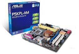
![]() Краткое руководство пользователя материнская плата ASUS P5KPL-AM.
Краткое руководство пользователя материнская плата ASUS P5KPL-AM.
Да, безусловно стоит внимательно прочитать настоящую инструкцию по эксплуатации материнской платы ASUS P5KPL-AM.
Процессор устанавливается на материнскую плату ASUS P5KPL-AM в строгом соответствии с требованием завода изготовителя. Инструкция применения советует не удалять защитную крышку во избежание повреждения контактов.
Материнская плата поддерживает общий объем оперативной памяти от 256 Мб до 1 Гб, но только если применяются не буферные модули DMM DDR2 (без ЕСС). Допускается установка разного объема памяти в слоты канала, учитывая, что для двух канальной конфигурации система покажет общий объем памяти. Полный объем памяти в этом случае будет визуально отображаться только в одноканальной конфигурации. Для лучшей совместимости мануал на русском языке материнская плата ASUS P5KPL-AM советует использовать модули памяти одного изготовителя. При установке двух модулей по 2Гб, система распознает только менее 3 Гб потому что адресное пространство предоставляется для другой работы. Такое происходит при Windows XP 32 бит. Эта материнская плата ASUS P5KPL-AM не поддерживает модули 128 Мб, двухсторонние 16-чиповые модули памяти. Загрузить инструкция пользователя плата.
Фирма ASUS – это одна из самых крупнейших производителей комплектующих для компьютеров. Помните, как в известных строках: «Мы говорим ASUS, подразумеваем компьютерная плата, мы говорим компьютерная плата, подразумеваем ASUS». Эта компания оставила далеко позади себя такие известные фирмы как Intel, Via, SiS, ALi и nVidia.
Первая материнская плата была сделана IBM и продемонстрирована летом 1981 года. Она поддерживала 64К памяти. Позже появился второй вариант, способный работать с 256К памяти.
Что входит в состав элементов материнской платы? Базовыми являются разъемы расширения, котроллер клавиатуры, системный BIOS, оперативная память и процессор.
В не далёком 1976 году фирма Intel начала работать над микропроцессором 8086. В отличие от предшественника 8080-го размер его регистров увеличили в два раза, что повысило производительность в десять раз! Размер информационных шин увеличили до 16 разрядов, что позволило повысить скорость передачи информации на и с микропроцессор в 2 раза. Также была увеличена адресная шина до 20 бит, что дало возможность контролировать 1М оперативной памяти.
Нельзя говорить о материнской плате, как об отдельном элементе компьютера – это часть комплекса, которая поддерживает работу компьютера. Основным фактором, влияющим на разработки материнских плат, является процесс совершенствование микропроцессоров. К примеру, Intel и HP давно уже трудятся над созданием нового процессора, который будет способен поддерживать процессоры для PC и процессоры, сделанные на архитектуре RISC. Вслед за этим материнские платы также поменяют свою конфигурацию. Поживём увидим чего там придумают специалисты этой области.
скачать файл документа
ASUS P5KPL-AM. pdf. File-Size: 1.12 Мб
The processor is installed on the ASUS P5KPL-AM motherboard in strict accordance with the manufacturer’s requirements. Instructions for use advises not to remove the protective cover in order to avoid damage to the contacts.
The motherboard supports a total amount of RAM from 256 MB to 1 GB, but only if non-buffer modules DMM DDR2 (without ESS) are used. It is allowed to install different amounts of memory in the channel slots, given that for a two-channel configuration, the system will show the total amount of memory. In this case, the full amount of memory will be visually displayed only in a single-channel configuration. For better compatibility manual in Russian, the ASUS P5KPL-AM motherboard advises using memory modules from the same manufacturer. When installing two 2GB modules, the system recognizes only less than 3 GB because the address space is provided for other work. This happens with Windows XP 32 bit. This ASUS P5KPL-AM motherboard does not support 128 MB modules, double-sided 16-chip memory modules. Download the user manual of the board.
ASUS is one of the largest manufacturers of computer components. Remember, as in the famous lines: «We say ASUS, we mean a computer board, we say a computer board, we mean ASUS.» This company has left such well-known companies as Intel, Via, SiS, ALi and nVidia far behind.
The first motherboard was made by IBM and demonstrated in the summer of 1981. It supported 64K of memory. Later, a second option appeared, capable of working with 256K of memory.
What is included in the components of the motherboard? The basic ones are expansion connectors, keyboard controller, system BIOS, RAM and processor.
Not far back in 1976, Intel began working on the 8086 microprocessor. Unlike its predecessor, the 8080th, the size of its registers was doubled, which increased performance tenfold! The size of the information buses was increased to 16 digits, which made it possible to increase the speed of information transfer to and from the microprocessor by 2 times. The address bus was also increased to 20 bits, which made it possible to control 1M of RAM.
It is impossible to talk about the motherboard as a separate element of the computer – it is part of the complex that supports the operation of the computer. The main factor influencing the development of motherboards is the process of improving microprocessors. For example, Intel and HP have been working for a long time to create a new processor that will be able to support PC processors and processors made on the RISC architecture. After that, the motherboards will also change their configuration. Let’s wait and see what the experts in this field will come up with.

14
ASUS P5KPL-AM IN/ROEM/SI
Ру
сс
ки
й
1.
Формат материнской платы
2.
Установка процессора
Для установки процессора выполните следующее:
1.
Нажмите на удерживающий рычаг большим пальцем (А), затем перемещайте его влево
(В) до тех пор, пока он не высвободится из-под фиксирующего язычка.
A
B
Удерживающий
рычаг
Фиксирующий
язычок
Отметка PnP
Эта сторона должна быть обращена к
устанавливающему.
PCIEX16
PCI2
PCI1
PRI_IDE
USB78
USB56
AAFP
IC
S
9LRS954A4GL
F
ATX12V
CPU_FAN
Intel
®
G31 B0
Lithium Cell
CMOS Power
VIA
VT1705
RTL
8131
ITE
IT8755E
8Mb
BIOS
SB_PWR
17.8cm(7.0in)
24.4cm(9.6in)
LGA775
Intel
®
ICH7
DDR2 DIMM_A1 (64bit, 240-pin module)
DDR2 DIMM_B1 (64bit, 240-pin module)
SATA2
SATA1
CLRTC
USBPW5-8
PS2_USBPW1-4
SPEAKER
AUDIO
KBMS
LAN1_USB12
USB34
F_PANEL
VG
A
EATXPW
R
1 2
2 3
Normal
(Default)
Clear RTC
CLRTC
PIN 1
PWR BTN
PLED
+
PLED
—
PWR
GND
IDE_LED
+
IDE_LED
—
Groun
d
Rese
t
F_PANEL
PWR LED
HD_LED
RESET
2
1
2
3
+5V
(Default)
+5VSB
PS2_USBPW1-4
2
1
2 3
+5V
(Default)
+5VSB
USBPW5-8
P5KPL-AM IN/ROEM/SI
COM
-
Страница 1
Motherboard P5KPL-AM[…]
-
Страница 2
ii E4198 Second Edition V2 September 2008 Copyright © 2008 ASUST eK Computer INC. All Rights Reserved. No part of this manual, including the products and software described in it, may be reproduced, transmitted, transcribed, stored in a retrieval system, or translated into any language in any form or by any means, except documentation kept by the […]
-
Страница 3
iii Contents Notices …………………………………………………………………………………………… vi Safety information …………………………………………………………………………. vii About this guide …………………………………………………………………………… viii P[…]
-
Страница 4
iv Contents Chapter 2: BIOS setup 2.1 Managing and updating your BIOS …………………………………….. 2-2 2.1.1 Creating a bootable oppy disk ………………………………… 2-2 2.1.2 ASUS EZ Flash 2 utility …………………………………………… 2-3 2.1.3 AFUDOS utility …………………………………..[…]
-
Страница 5
v Contents 2.5.4 APM Conguration ………………………………………………. 2-28 2.5.5 Hardware Monitor ………………………………………………… 2-29 2.6 Boot menu ………………………………………………………………………. 2-30 2.6.1 Boot Device Priority ………………………………..[…]
-
Страница 6
vi Notices Federal Communications Commission Statement This device complies with Part 15 of the FCC Rules. Operation is subject to the following two conditions: • This device may not cause harmful interference, and • This device must accept any interference received including interference that may cause undesired operation. This equipment has b[…]
-
Страница 7
vii Safety information Electrical safety • T o prevent electrical shock hazard, disconnect the power cable from the electrical outlet before relocating the system. • When adding or removing devices to or from the system, ensure that the power cables for the devices are unplugged before the signal cables are connected. If possible, disconnect al[…]
-
Страница 8
viii About this guide This user guide contains the information you need when installing and conguring the motherboard. How this guide is organized This manual contains the following parts: • Chapter 1: Product introduction This chapter describes the features of the motherboard and the new technology it supports. It also lists the hardware setu[…]
-
Страница 9
ix Conventions used in this guide T o make sure that you perform certain tasks properly , take note of the following symbols used throughout this manual. T ypography Bold text Indicates a menu or an item to select. Italics Used to emphasize a word or a phrase. <Key> Key s encl osed i n the less- than a nd gre ater-t han s ign mea ns tha t you[…]
-
Страница 10
x P5KPL-AM specications summary (continued on the next page) CPU LGA775 socket for Intel ® Core™2 Quad/ Core™2 Extreme / Core™2 Duo / Pentium ® D / Pentium ® 4 / Celeron ® E1000 Series and Celeron 400 Series Processors Compatible with Intel ® 05B / 05A / 06 processors Intel ® Hyper-Threading T echnology ready Support Intel ® EIST te[…]
-
Страница 11
xi P5KPL-AM specications summary Internal connectors 2 x U SB 2 .0 con nec tor s sup port s a ddi tio nal 4 U SB por ts 1 x Floppy disk drive connector 1 x IDE connector for two devices 4 x Serial A T A connectors 1 x CPU fan connector 1 x Chassis fan connector 1 x Power fan connector 1 x S/PDIF Out connector 1 x Chassis intrusion connector 1 x […]
-
Страница 12
xii[…]
-
Страница 13
1 Product introduction This chapter describes the motherboard features and the new technologies it supports.[…]
-
Страница 14
1-2 Chapter 1: Product introduction 1.1 Welcome! Thank you for buying an ASUS ® P5KPL-AM motherboard! The motherboard delivers a host of new features and latest technologies, making it another standout in the long line of ASUS quality motherboards! Before you start installing the motherboard, and hardware devices on it, check the items in your pac[…]
-
Страница 15
ASUS P5KPL-AM 1-3 Intel® Core™2 Processor Ready Th is mot her bo ard su ppo rts th e l ate st I nte l® Co re ™2 pro ces so rs in LG A77 5 pac kag e. Wi th new In te l® Co re™ m ic roa rch ite ct ur e t ech no lo gy and 16 00 (O C) MHz FS B, In tel ® Co re™ 2 p roc es sor is on e o f t he mos t po wer ful a nd en erg y e f ci ent CP U[…]
-
Страница 16
1-4 Chapter 1: Product introduction High Denition Audio Enjoy high-end sound system on your PC! The onboard HD audio (High Denition Audio, previously codenamed Azalia) CODEC enables high-quality 192KHz/24- bit audio output, jack-sensing feature, retasking functions and multi-streaming technology that simultaneously sends different audio strea[…]
-
Страница 17
ASUS P5KPL-AM 1-5 C.P .R. (CPU Parameter Recall) The C.P .R. feature of the motherboard BIOS allows automatic re-setting to the BIOS default settings in case the system hangs due to overclocking. When the system hangs due to overclocking, C.P .R. eliminates the need to open the system chassis and clear the RTC data. Simply shut down and reboot the […]
-
Страница 18
1-6 Chapter 1: Product introduction 1.4 Before you proceed T ake note of the following precautions before you install motherboard components or change any motherboard settings. • Unplug the power cord from the wall socket before touching any component. • Use a grounded wrist strap or touch a safely grounded object or a metal object, such as the[…]
-
Страница 19
ASUS P5KPL-AM 1-7 P5KPL-AM 1.5 Motherboard overview Before you install the motherboard, study the conguration of your chassis to ensure that the motherboard ts into it. Do not overtighten the screws! Doing so can damage the motherboard. 1.5.1 Placement direction When installing the motherboard, make sur e that you place it into the chassis in[…]
-
Страница 20
1-8 Chapter 1: Product introduction 1.5.3 Motherboard layout Refer to section 1.10 Connectors for more information about rear panel connectors and internal connectors. Intel G31 Intel ICH7 24.4cm(9.6in) DDR2 DIMM1 (64 bit,240-pin module) DDR2 DIMM 2 (64 bit,240-pin module) PCIEX16 PCI1 PCI2 PCIEX1_1 CD VT1708B AAFP USB78 USB56 CLRTC F_ P AN EL SB_P[…]
-
Страница 21
ASUS P5KPL-AM 1-9 1.6 Central Processing Unit (CPU) The motherboard comes with a surface mount LGA775 socket designed for the Intel ® Core™2 Quad / Core™2 Extreme / Core™2 Duo / Pentium ® D / Pentium ® 4 and Celeron ® E1000 Series and Celeron 400 Series processors. • Upon purchase of the motherboard, make sure that the PnP cap is on the[…]
-
Страница 22
1-10 Chapter 1: Product introduction T o prevent damage to the socket pins, do not remove the PnP cap unless you are installing a CPU. 2. Press the load lever with your thumb (A), then move it to the left (B) until it is released from the retention tab. A B Load lever Retention tab 3. Lift the load lever in the direction of the arrow to a 135º ang[…]
-
Страница 23
ASUS P5KPL-AM 1-1 1 6. Apply several drops of thermal paste to the exposed area of the CPU that the heatsink will be in contact with, ensuring that it is spread in an even thin layer . Some heatsinks come with pre- applied thermal paste. If so, skip this step. The Thermal Interface Material is toxic and inedible. If it gets into your eyes or touche[…]
-
Страница 24
1-12 Chapter 1: Product introduction 1.6.2 Installing the CPU heatsink and fan The Intel ® LGA775 processor requires a specially designed heatsink and fan assembly to ensure optimum thermal condition and performance. • When you buy a boxed Intel ® processor , the package includes the CPU fan and heatsink assembly . If you buy a CPU separately ,[…]
-
Страница 25
ASUS P5KPL-AM 1-13 • Do not forget to connect the CPU fan connector! Hardware monitoring errors can occur if you fail to plug this connector . • We recommend you to install the chassis fan for better thermal state. 3. When the fan and heatsink assembly is in place, connect the CPU fan cable to the connector on the motherboard labeled CPU_F AN. […]
-
Страница 26
1-14 Chapter 1: Product introduction T o uninstall the CPU heatsink and fan 1. Disconnect the CPU fan cable from the connector on the motherboard. 2. Rotate each fastener counterclockwise. 3. Pull up two fasteners at a time in a diagonal sequence to disengage the heatsink and fan assembly from the motherboard. A A B B A A B B 4. Carefully remove th[…]
-
Страница 27
ASUS P5KPL-AM 1-15 1.7 System memory 1.7.1 Overview The motherboard comes with two Double Data Rate 2 (DDR2) Dual Inline Memory Modules (DIMM) sockets. A DDR2 module has the same physical dimensions as a DDR DIMM but has a 240-pin footprint compared to the 184-pin DDR DIMM. DDR2 DIMMs are notched differently to prevent installation on a DDR DIMM so[…]
-
Страница 28
1-16 Chapter 1: Product introduction 1.7.2 Memory congurations Y ou may install 256 MB, 512 MB, 1 GB and 2 GB unbuffered non-ECC DDR2 DIMMs into the DIMM sockets. • Y ou may install varying memory sizes in Channel A and Channel B. The system maps the total size of the lower-sized channel for the dual-channel conguration. Any excess memory f[…]
-
Страница 29
ASUS P5KPL-AM 1-17 Qualied V endors Lists (QVL) Size V endor Model CL Brand S S / DS Component DIMM support A* B* 256MB Kingston KVR667D2N5/256 N/A Elpida SS E2508AB-6E-E • • 256MB Kingston KVR667D2N5/256 N/A Kingston SS D3216TLSAKL3U • • 256MB Kingston KVR667D2N5/256 N/A Inneon SS HYB18T256800AF3SW65 33154 • • 512MB Kingston KVR6[…]
-
Страница 30
1-18 Chapter 1: Product introduction Size V endor Model CL Brand S S / DS Component DIMM support A* B* 1G AENEON AET760UD00-30DA98Z N/A AENEON DS AET93F30DA 0604 • • 1G AENEON AET760UD00-30DB97X 5 AENEON DS AET93R300B 0639 • • 512MB T AKEMS TMS51B264C081-665QI 5 takeMS SS MS18T51280-3 • • 512MB T AKEMS TMS51B264C081-665AP 5 takeMS SS MS[…]
-
Страница 31
ASUS P5KPL-AM 1-19 Size V endor Model CL Brand SS/DS Component DIMM support A* B* 1G PSC AL7E8E63B-8E1K 5 PSC DS A3R12E3HEF641B9A05 • • 512MB AENEON AET660UD00-25DB98X N/A AENEON SS AET93F25DB 0621 • • 1G AENEON AET760UD00-25DB97X 5 AENEON DS AET93R25DB 0640 • • 512MB SIS SL Y264M8-JGE-3 N/A SIS SS DDRII6408-8E 7212 • • 1G SIS SL Y2[…]
-
Страница 32
1-20 Chapter 1: Product introduction 1.7.3 Installing a DIMM 3. Firmly insert the DIMM into the socket until the retaining clips snap back in place and the DIMM is properly seated. A DDR2 DIMM is keyed with a notch so that it ts in only one direction. DO NOT force a DIMM into a socket to avoid damaging the DIMM. Make sure to unplug the power sup[…]
-
Страница 33
ASUS P5KPL-AM 1-21 1.8 Expansion slots In the future, you may need to install expansion cards. The following sub-sections describe the slots and the expansion cards that they support. 1.8.1 Installing an expansion card T o install an expansion card: 1. Before installing the expansion card, read the documentation that came with it and make the neces[…]
-
Страница 34
1-22 Chapter 1: Product introduction 1.8.3 Interrupt assignments * These IRQs are usually available for PCI devices. Standard interrupt assignments IRQ Priority Standard Function 0 1 System T imer 1 2 Keyboard Controller 2 — Re-direct to IRQ#9 3 10 Communications Port (COM1) 4 1 1 IRQ holder for PCI steering* 5 12 Standard Floppy Disk Controller […]
-
Страница 35
ASUS P5KPL-AM 1-23 1.8.4 PCI slot The PCI slot supports cards such as a LAN card, SCSI card, USB card, and other cards that comply with PCI specications. The gure shows a LAN card installed on a PCI slot. 1.8.6 PCI Express x16 Slot This motherboard supports one PCI Express x16 graphics card. The gure shows a graphics card installed on the […]
-
Страница 36
1-24 Chapter 1: Product introduction 1.9 Jumpers 1. Clear RTC RAM (CLRTC) This jumper allows you to clear the Real T ime Clock (RTC) RAM in CMOS. Y ou can clear the CMOS memory of date, time, and system setup parameters by erasing the CMOS RTC RAM data. The onboard button cell battery powers the RAM data in CMOS, which include system setup informat[…]
-
Страница 37
ASUS P5KPL-AM 1-25 1.10 Connectors 1.10.1 Rear panel connectors 1. PS/2 mouse port (green). This port is for a PS/2 mouse. 2. Parallel port. This 25-pin port connects a parallel printer , a scanner , or other devices. 3. LAN (RJ-45) port. Supported by Realtek 10/100 LAN controller , this port allows 10/100 connection to a Local Area Network (LAN) t[…]
-
Страница 38
1-26 Chapter 1: Product introduction 10. USB 2.0 ports 1 and 2. These two 4-pin Universal Serial Bus (USB) ports are available for connecting USB 2.0 devices. 1 1. USB 2.0 ports 3 and 4. These two 4-pin Universal Serial Bus (USB) ports are available for connecting USB 2.0 devices. 12. Video Graphics Adapter port. This 15-pin port is for a VGA monit[…]
-
Страница 39
ASUS P5KPL-AM 1-27 1.10.2 Internal connectors 1. Floppy disk drive connector (34-1 pin FLOPPY) This connector is for the provided oppy disk drive (FDD) signal cable. Insert one end of the cable to this connector , then connect the other end to the signal connector at the back of the oppy disk drive. Pin 5 on the connector is removed to preven[…]
-
Страница 40
1-28 Chapter 1: Product introduction 3. IDE connector (40-1 pin PRI_IDE) The onboard IDE connector is for the Ultra DMA 100/66/33 signal cable. There are three connectors on each Ultra DMA 100/66/33 signal cable: blue, black, and gray . Connect the blue connector to the motherboard’s IDE connector , then select one of the following modes to con?[…]
-
Страница 41
ASUS P5KPL-AM 1-29 4. ICH7 Serial A T A connectors (7-pin SA T A1, SA T A2, SA T A3, SA T A4) These connectors are for the Serial A T A signal cables for Serial A T A hard disk drives. Connect the right-angle side o f S ATA s i g n a l c a b l e t o S AT A device. Or you may connect the right-angle side of SA T A cable to the onboard SA T A port to[…]
-
Страница 42
1-30 Chapter 1: Product introduction 5. USB connectors (10-1 pin USB56, USB78) These connectors are for USB 2.0 ports. Connect the USB module cable to any of these connectors, then install the module to a slot opening at the back of the system chassis. These USB connectors comply with USB 2.0 specication that supports up to 480 Mbps connection s[…]
-
Страница 43
ASUS P5KPL-AM 1-31 7. CPU, chassis, power fan connectors (4-pin CPU_F AN, 3-pin CHA_F AN, 3-pin PWR_F AN) The fan c onnect ors su pport co oling fans o f 350 mA ~ 2000 mA (24 W max.) or a total of 1 A ~ 7 A (84 W max.) at +12V . Connect the fan cables to the fan connectors on the motherboard, making sure that the black wire of each cable matches th[…]
-
Страница 44
1-32 Chapter 1: Product introduction 9. Front panel audio connector (10-1 pin AAFP) Th is con nec to r is for a c has sis -mo un te d f ron t pa nel au dio I /O mo dul e t ha t su ppo rts ei th er HD Au di o or leg acy A C’ 97 aud io s tan dar d. • We recommend that you connect a high-denition front panel audio module to this connector to av[…]
-
Страница 45
ASUS P5KPL-AM 1-33 • For a fully congured system, we recommend that you use a power supply unit (PSU) that complies with A TX 12 V Specication 2.0 (or later version) and provides a minimum power of 400 W . • Do not forget to connect the 4-pin A TX12V power plug; otherwise, the system will not boot. • Use of a PSU with a higher power out[…]
-
Страница 46
1-34 Chapter 1: Product introduction 1 1. System panel connector (10-1 pin F_P ANEL) This connector supports several chassis-mounted functions. • System power LED (2-pin PWRLED) This 2-pin connector is for the system power LED. Connect the chassis power LED cable to this connector . The system power LED lights up when you turn on the system power[…]
-
Страница 47
ASUS P5KPL-AM 2-1 2 BIOS setup This chapter tells how to change the system settings through the BIOS Setup menus. Detailed descriptions of the BIOS parameters are also provided.[…]
-
Страница 48
2-2 Chapter 2: BIOS setup 2.1 Managing and updating your BIOS The following utilities allow you to manage and update the motherboard Basic Input/Output System (BIOS) setup. 1. ASUS EZ Flash 2 (Updates the BIOS in DOS mode using a oppy disk or USB ash disk.) 2. ASUS AFUDOS (Updates the BIOS in DOS mode using a bootable oppy disk.) 3. ASUS C[…]
-
Страница 49
ASUS P5KPL-AM 2-3 Windows ® Vista environment a. Insert a formatted, high density 1.44 MB oppy disk to the oppy disk drive. b. Click from the Windows ® desktop, then select Computer . c. Right-click Floppy Disk Drive then click Format to display the Format 3 1/2 Floppy dialog box. d. Select the Create an MS-DOS startup disk check box. e. Cl[…]
-
Страница 50
2-4 Chapter 2: BIOS setup 2.1.3 AFUDOS utility The AFUDOS utility allows you to update the BIOS le in DOS environment using a bootable oppy disk with the updated BIOS le. This utility also allows you to copy the current BIOS le that you can use as backup when the BIOS fails or gets corrupted during the updating process. Copying the curr[…]
-
Страница 51
ASUS P5KPL-AM 2-5 Updating the BIOS le T o update the BIOS le using the AFUDOS utility: 1. Visit the ASUS website (www .asus.com) and download the latest BIOS le for the motherboard. Save the BIOS le to a bootable oppy disk. 2. Copy the AFUDOS utility (afudos.exe) from the motherboard support DVD to the bootable oppy disk you crea[…]
-
Страница 52
2-6 Chapter 2: BIOS setup 2.1.4 ASUS CrashFree BIOS 3 utility The ASUS CrashFree BIOS 3 is an auto recovery tool that allows you to restore the BIOS le when it fails or gets corrupted during the updating process. Y ou can update a corrupted BIOS le using the motherboard support DVD , the oppy disk or the USB ash disk that contains the u[…]
-
Страница 53
ASUS P5KPL-AM 2-7 Recovering the BIOS from the support DVD T o recover the BIOS from the support DVD: 1. Remove any oppy disk from the oppy disk drive, then turn on the system. 2. Insert the support DVD to the optical drive. 3. The utility displays the following message and automatically checks the oppy disk for the original or updated BIO[…]
-
Страница 54
2-8 Chapter 2: BIOS setup Installing ASUS Update T o install ASUS Update: 1. Place the support DVD in the optical drive. The Drivers menu appears. 2. Click the Utilities tab, then click Install ASUS Update . See page 2-3 for the Utilities screen menu. 3. The ASUS Update utility is copied to your system. 2.1.5 ASUS Update utility The ASUS Update is […]
-
Страница 55
ASUS P5KPL-AM 2-9 3. Select the ASUS FTP site nearest you to avoid network trafc, or click Auto Select . Click Next . Updating the BIOS through the Internet T o update the BIOS through the Internet: 1. Launch the ASUS Update utility from the Windows ® desktop by clicking Start > Programs > ASUS > ASUSUpdate > ASUSUpdate . The ASUS U[…]
-
Страница 56
2-10 Chapter 2: BIOS setup Updating the BIOS through a BIOS le T o update the BIOS through a BIOS le: 1. Launch the ASUS Update utility from the Windows ® desktop by clicking Start > Programs > ASUS > ASUSUpdate > ASUSUpdate . The ASUS Update main window appears. 2. Select Update BIOS from a le option from the drop-down menu, […]
-
Страница 57
ASUS P5KPL-AM 2-1 1 • The default BIOS settings for this motherboard apply for most conditions to ensure optimum performance. If the system becomes unstable after changing any BIOS settings, load the default settings to ensure system compatibility and stability . Select the Load Setup Defaults item under the Exit Menu. See section “2.8 Exit Men[…]
-
Страница 58
2-12 Chapter 2: BIOS setup 2.2.2 Menu bar The menu bar on top of the screen has the following main items: Main For changing the basic system conguration Advanced For changing the advanced system settings Power For changing the advanced power management (APM) conguration Boot For changing the system boot conguration T ools For conguring […]
-
Страница 59
ASUS P5KPL-AM 2-13 2.2.4 Menu items The highlighted item on the menu bar displays the specic items for that menu. For example, selecting Main shows the Main menu items. The other items (Advanced, Power , Boot, T ool, and Exit) on the menu bar have their respective menu items. 2.2.5 Sub-menu items A solid triangle before each item on any menu scr[…]
-
Страница 60
2-14 Chapter 2: BIOS setup 2.3 Main menu When you enter the BIOS Setup program, the Main menu screen appears, giving you an overview of the basic system information. 2.3.1 System Time [xx:xx:xx] Allows you to set the system time. 2.3.2 System Date [Day xx/xx/xxxx] Allows you to set the system date. 2.3.3 Legacy Diskette A [1.44M, 3.5 in.] Sets the […]
-
Страница 61
ASUS P5KPL-AM 2-15 2.3.4 Primary , Third and Fourth IDE Master/Slave While entering Setup, the BIOS automatically detects the presence of IDE devices. There is a separate sub-menu for each IDE device. Select a device item then press <Enter> to display the IDE device information. The BIOS automatically detects the values opposite the dimmed it[…]
-
Страница 62
2-16 Chapter 2: BIOS setup PIO Mode [Auto] Selects the PIO mode. Conguration options: [Auto] [0] [1] [2] [3] [4] DMA Mode [Auto] Selects the DMA mode. Conguration options: [Auto] SMART Monitoring [Auto] Sets the Smart Monitoring, Analysis, and Reporting T echnology . Conguration options: [Auto] [Disabled] [Enabled] 32Bit Data T ransfer [En[…]
-
Страница 63
ASUS P5KPL-AM 2-17 2.3.6 System Information This menu gives you an overview of the general system specications. The BIOS automatically detects the items in this menu. AMI BIOS Displays the auto-detected BIOS information. Processor Displays the auto-detected CPU specication. System Memory Displays the auto-detected system memory . AMIBIOS Vers[…]
-
Страница 64
2-18 Chapter 2: BIOS setup Select Screen Select Item Enter Go to Sub-screen F1 General Help F10 Save and Exit ESC Exit 2.4 Advanced menu The Advanced menu items allow you to change the settings for the CPU and other system devices. T ake caution when changing the settings of the Advanced menu items. Incorrect eld values can cause the system to m[…]
-
Страница 65
ASUS P5KPL-AM 2-19 Overclock Options [Overclock 5%] Allows selection of CPU overclocking options to achieve desired CPU internal frequency . Conguration options: [Overclock 5%] [Overclock 10%] [Overclock 15%] [Overclock 20%] [Overclock 30%] DRAM Frequency [Auto] Allows you to set the DDR2 operating frequency . Conguration options (for 1600MHz[…]
-
Страница 66
2-20 Chapter 2: BIOS setup USB Functions [Enabled] Allows you to disable or select the different values of the USB functions. Conguration options: [Disabled] [2 USB Ports] [4 USB Ports] [6 USB Ports] [8 USB Ports] USB 2.0 Controller [Enabled] Allows you to enable or disable USB 2.0 controller . Conguration options: [Enabled] [Disabled] Legacy[…]
-
Страница 67
ASUS P5KPL-AM 2-21 2.4.3 CPU Conguration The items in this menu show the CPU-related information that the BIOS automatically detects. Congure advanced CPU settings Module Version: 3C.0E Manufacturer: Intel Brand String: Genuine Intel(R) CPU 2.80GHz Frequency : 2.80GHz FSB Speed : 800MHz Cache L1 : 32 KB Cache L2 : 2048 KB Ratio Status: Unlock[…]
-
Страница 68
2-22 Chapter 2: BIOS setup CPU TM function [Enabled] Enables or disables Intel® CPU Thermal Monitor (TM2) function, a CPU overheating protection function. When enabled, the CPU core frequency and voltage is reduced when the CPU is overheats. Conguration options: [Enabled] [Disabled] Execute Disable Bit [Enabled] Allows you to Enable/disable Exe[…]
-
Страница 69
ASUS P5KPL-AM 2-23 2.4.4 Chipset The Chipset menu allows you to change the advanced chipset settings. Select an item then press <Enter> to display the sub-menu. Advanced Chipset Settings WARNING: Setting wrong values in below sections may cause system to malfunction. North Bridge Conguration South Bridge Conguration North Bridge chipset[…]
-
Страница 70
2-24 Chapter 2: BIOS setup Video Function Conguration Video Function Conguration DVMT Mode Select [DVMT Mode] DVMT/FIXED Memory [256MB] DVMT Mode Select [DVMT Mode] Allows you to select the DVMT Mode. Conguration options: [Fixed Mode] [DVMT Mode] DVMT/FIXED Memory [256MB] Allows you to select the amount of the DVMT/FIXED Memory . Congur[…]
-
Страница 71
ASUS P5KPL-AM 2-25 2.4.5 Onboard Devices Conguration Congure Win627DHG-A Super IO Chipset Onboard PCIE GbE LAN [Enabled] LAN Option ROM [Disabled] Serial Port1 Address [3F8/IRQ4] Parallel Port Address [378] Parallel Port Mode [ECP] ECP Mode DMA Channel [DMA3] Parallel Port IRQ [IRQ7] Onboard PCIE GbE LAN [Enabled] Allows you to enable or disa[…]
-
Страница 72
2-26 Chapter 2: BIOS setup 2.4.6 PCI PnP The PCI PnP menu items allow you to change the advanced settings for PCI/PnP devices. The menu includes setting IRQ and DMA channel resources for either PCI/PnP or legacy ISA devices, and setting the memory size block for legacy ISA devices. T ake caution when changing the settings of the PCI PnP menu items.[…]
-
Страница 73
ASUS P5KPL-AM 2-27 Select Screen Select Item +- Change Option F1 General Help F10 Save and Exit ESC Exit 2.5 Power menu The Power menu items allow you to change the settings for the Advanced Power Management (APM). Select an item then press <Enter> to display the conguration options. 2.5.1 Suspend Mode [Auto] Allows you to select the Advan[…]
-
Страница 74
2-28 Chapter 2: BIOS setup 2.5.4 APM Conguration APM Conguration Restore on AC Power Loss [Power Off] Power On by RTC Alarm [Disabled] Power On by External Modems [Disabled] Power On PCI Devices [Disabled] Power On By PCIE Devices [Disabled] Power On By PS/2 Keyboard [Disabled] Power On By PS/2 Mouse [Disabled] Restore on AC Power Loss [Power[…]
-
Страница 75
ASUS P5KPL-AM 2-29 2.5.5 Hardware Monitor Hardware Monitor CPU Temperature [55.5ºC/131.5ºF] MB Temperature [32ºC/89.5ºC] CPU Fan Speed [2884RPM] CPU Q-Fan Control [Disabled] Chassis Fan Speed [N/A] Power Fan Speed [N/A] VCORE Voltage [ 1.344V] 3.3V Voltage [ 3.280V] 5V Voltage [ 5.145V] 12V Voltage [11.932V] CPU T emperature [xxxºC/xxxºF] The[…]
-
Страница 76
2-30 Chapter 2: BIOS setup Select Screen Select Item Enter Go to Sub-screen F1 General Help F10 Save and Exit ESC Exit 2.6 Boot menu The Boot menu items allow you to change the system boot options. Select an item then press <Enter> to display the sub-menu. Boot settings Boot Device Priority Boot Settings Conguration Security 2.6.1 Boot Dev[…]
-
Страница 77
ASUS P5KPL-AM 2-31 2.6.2 Boot Settings Conguration Select Screen Select Item +- Change Option F1 General Help F10 Save and Exit ESC Exit Boot Settings Conguration Quick Boot [Enabled] Full Screen Logo [Enabled] AddOn ROM Display Mode [Force BIOS] Bootup Num-Lock [On] PS/2 Mouse Support [Auto] Wait For ‘F1’ If Error [Enabled] Hit ‘DEL’[…]
-
Страница 78
2-32 Chapter 2: BIOS setup Hit ‘DEL’ Message Display [Enabled] When set to Enabled, the system displays the message “Press DEL to run Setup” during POST . Conguration options: [Disabled] [Enabled] Interrupt 19 Capture [Disabled] When set to [Enabled], this function allows the option ROMs to trap Interrupt 19. Conguration options: [Dis[…]
-
Страница 79
ASUS P5KPL-AM 2-33 Note ASUSTek EZ Flash 2 BIOS ROM Utility V3.06 Current ROM Update ROM A: FLASH TYPE: MXIC 25L8005 PATH: A: BOARD: P5KPL-AM VER: 0301 DATE: 04/24/08 BOARD: Unknown VER: Unknown DATE: Unknown [Enter] Select or Load [B] Backup [ESC] Exit [Tab] Switch [Up/Down/Home/End] Move Note 2.7 Tools menu The T ools menu items allow you to lau[…]
-
Страница 80
2-34 Chapter 2: BIOS setup Exit system setup after saving the changes. F10 key can be used for this operation. Select Screen Select Item Enter Go to Sub-screen F1 General Help F10 Save and Exit ESC Exit Exit & Discard Changes Select this option only if you do not want to save the changes that you made to the Setup program. If you made changes t[…]
-
Страница 81
ASUS P5KPL-AM 3-1 3 Software support This chapter describes the contents of the support DVD that comes with the motherboard package.[…]
-
Страница 82
3-2 Chapter 3: Software support If Autorun is NOT enabled in your computer , browse the contents of the support CD to locate the le ASSETUP .EXE from the BIN folder . Double-click the ASSETUP .EXE to run the DVD. Click an item to install 3.1 Installing an operating system This motherboard supports Windows ® 32-bit XP/32-bit Vista/64-bit XP/64-b[…]
-
Страница 83
ASUS P5KPL-AM 3-3 3.2.2 Drivers menu The drivers menu shows the available device drivers if the system detects installed devices. Install the necessary drivers to activate the devices. ASUS InstAll-Drivers Installation Wizard Installs the ASUS InstAll-Drivers Installation Wizard. Intel Chipset Inf Update Program Installs the Intel ® chipset Inf up[…]
-
Страница 84
3-4 Chapter 3: Software support 3.2.3 Utilities menu The Utilities menu shows the applications and other software that the motherboard supports. ASUS InstAll-Installation Wizard for Utilities Installs all of the utilities through the Installation Wizard. ASUS Update The ASUS Update utility allows you to update the motherboard BIOS in a Windows ® e[…]
-
Страница 85
ASUS P5KPL-AM 3-5 3.2.4 ASUS Contact information Click the Contact tab to display the ASUS contact information. Y ou can also nd this information on the inside front cover of this user guide.[…]
-
Страница 86
3-6 Chapter 3: Software support[…]
-
Страница 87
A CPU features The Appendix describes the CPU features that the motherboard supports.[…]
-
Страница 88
A-2 Appendix: CPU features A.1 Enhanced Intel SpeedStep ® Technology (EIST) A.1.1 System requirements Before using EIST , check your system if it meets the following requirements: • Intel ® Pentium ® 4 processor with EIST support • BIOS le with EIST support • Operating system with EIST support (Windows ® XP SP2/Linux 2.6 kernel or late[…]
-
Страница 89
ASUS P5KPL-AM A-3 8. On the Power schemes section, click , then select any option except Home/Ofce Desktop or Always On. 9. Click Apply , then click OK . 10. Close the Display Properties window . After you adjust the power scheme, the CPU internal frequency slightly decreases when the CPU loading is low . The screen displays and procedures may v[…]
-
Страница 90
A-4 Appendix: CPU features A.2 Intel ® Hyper-Threading Technology Using the Hyper-Threading T echnology T o use the Hyper-Threading T echnology: 1. Install an Intel ® Pentium ® 4 CPU that supports Hyper-Threading T echnology . 2. Power up the system and enter the BIOS Setup. Under the Advanced Menu, make sure that the item Hyper-Threading T echn[…]
-
Page 1: Asus P5KPL-AM
Motherboard P5KPL-AM[…]
-
Page 2: Asus P5KPL-AM
ii E4198 Second Edition V2 September 2008 Copyright © 2008 ASUST eK Computer INC. All Rights Reserved. No part of this manual, including the products and software described in it, may be reproduced, transmitted, transcribed, stored in a retrieval system, or translated into any language in any form or by any means, except documentation kept by the […]
-
Page 3: Asus P5KPL-AM
iii Contents Notices …………………………………………………………………………………………… vi Safety information …………………………………………………………………………. vii About this guide …………………………………………………………………………… viii P[…]
-
Page 4: Asus P5KPL-AM
iv Contents Chapter 2: BIOS setup 2.1 Managing and updating your BIOS …………………………………….. 2-2 2.1.1 Creating a bootable oppy disk ………………………………… 2-2 2.1.2 ASUS EZ Flash 2 utility …………………………………………… 2-3 2.1.3 AFUDOS utility …………………………………..[…]
-
Page 5: Asus P5KPL-AM
v Contents 2.5.4 APM Conguration ………………………………………………. 2-28 2.5.5 Hardware Monitor ………………………………………………… 2-29 2.6 Boot menu ………………………………………………………………………. 2-30 2.6.1 Boot Device Priority ………………………………..[…]
-
Page 6: Asus P5KPL-AM
vi Notices Federal Communications Commission Statement This device complies with Part 15 of the FCC Rules. Operation is subject to the following two conditions: • This device may not cause harmful interference, and • This device must accept any interference received including interference that may cause undesired operation. This equipment has b[…]
-
Page 7: Asus P5KPL-AM
vii Safety information Electrical safety • T o prevent electrical shock hazard, disconnect the power cable from the electrical outlet before relocating the system. • When adding or removing devices to or from the system, ensure that the power cables for the devices are unplugged before the signal cables are connected. If possible, disconnect al[…]
-
Page 8: Asus P5KPL-AM
viii About this guide This user guide contains the information you need when installing and conguring the motherboard. How this guide is organized This manual contains the following parts: • Chapter 1: Product introduction This chapter describes the features of the motherboard and the new technology it supports. It also lists the hardware setu[…]
-
Page 9: Asus P5KPL-AM
ix Conventions used in this guide T o make sure that you perform certain tasks properly , take note of the following symbols used throughout this manual. T ypography Bold text Indicates a menu or an item to select. Italics Used to emphasize a word or a phrase. <Key> Key s encl osed i n the less- than a nd gre ater-t han s ign mea ns tha t you[…]
-
Page 10: Asus P5KPL-AM
x P5KPL-AM specications summary (continued on the next page) CPU LGA775 socket for Intel ® Core™2 Quad/ Core™2 Extreme / Core™2 Duo / Pentium ® D / Pentium ® 4 / Celeron ® E1000 Series and Celeron 400 Series Processors Compatible with Intel ® 05B / 05A / 06 processors Intel ® Hyper-Threading T echnology ready Support Intel ® EIST te[…]
-
Page 11: Asus P5KPL-AM
xi P5KPL-AM specications summary Internal connectors 2 x U SB 2 .0 con nec tor s sup port s a ddi tio nal 4 U SB por ts 1 x Floppy disk drive connector 1 x IDE connector for two devices 4 x Serial A T A connectors 1 x CPU fan connector 1 x Chassis fan connector 1 x Power fan connector 1 x S/PDIF Out connector 1 x Chassis intrusion connector 1 x […]
-
Page 12: Asus P5KPL-AM
xii[…]
-
Page 13: Asus P5KPL-AM
1 Product introduction This chapter describes the motherboard features and the new technologies it supports.[…]
-
Page 14: Asus P5KPL-AM
1-2 Chapter 1: Product introduction 1.1 Welcome! Thank you for buying an ASUS ® P5KPL-AM motherboard! The motherboard delivers a host of new features and latest technologies, making it another standout in the long line of ASUS quality motherboards! Before you start installing the motherboard, and hardware devices on it, check the items in your pac[…]
-
Page 15: Asus P5KPL-AM
ASUS P5KPL-AM 1-3 Intel® Core™2 Processor Ready Th is mot her bo ard su ppo rts th e l ate st I nte l® Co re ™2 pro ces so rs in LG A77 5 pac kag e. Wi th new In te l® Co re™ m ic roa rch ite ct ur e t ech no lo gy and 16 00 (O C) MHz FS B, In tel ® Co re™ 2 p roc es sor is on e o f t he mos t po wer ful a nd en erg y e f ci ent CP U[…]
-
Page 16: Asus P5KPL-AM
1-4 Chapter 1: Product introduction High Denition Audio Enjoy high-end sound system on your PC! The onboard HD audio (High Denition Audio, previously codenamed Azalia) CODEC enables high-quality 192KHz/24- bit audio output, jack-sensing feature, retasking functions and multi-streaming technology that simultaneously sends different audio strea[…]
-
Page 17: Asus P5KPL-AM
ASUS P5KPL-AM 1-5 C.P .R. (CPU Parameter Recall) The C.P .R. feature of the motherboard BIOS allows automatic re-setting to the BIOS default settings in case the system hangs due to overclocking. When the system hangs due to overclocking, C.P .R. eliminates the need to open the system chassis and clear the RTC data. Simply shut down and reboot the […]
-
Page 18: Asus P5KPL-AM
1-6 Chapter 1: Product introduction 1.4 Before you proceed T ake note of the following precautions before you install motherboard components or change any motherboard settings. • Unplug the power cord from the wall socket before touching any component. • Use a grounded wrist strap or touch a safely grounded object or a metal object, such as the[…]
-
Page 19: Asus P5KPL-AM
ASUS P5KPL-AM 1-7 P5KPL-AM 1.5 Motherboard overview Before you install the motherboard, study the conguration of your chassis to ensure that the motherboard ts into it. Do not overtighten the screws! Doing so can damage the motherboard. 1.5.1 Placement direction When installing the motherboard, make sur e that you place it into the chassis in[…]
-
Page 20: Asus P5KPL-AM
1-8 Chapter 1: Product introduction 1.5.3 Motherboard layout Refer to section 1.10 Connectors for more information about rear panel connectors and internal connectors. Intel G31 Intel ICH7 24.4cm(9.6in) DDR2 DIMM1 (64 bit,240-pin module) DDR2 DIMM 2 (64 bit,240-pin module) PCIEX16 PCI1 PCI2 PCIEX1_1 CD VT1708B AAFP USB78 USB56 CLRTC F_ P AN EL SB_P[…]
-
Page 21: Asus P5KPL-AM
ASUS P5KPL-AM 1-9 1.6 Central Processing Unit (CPU) The motherboard comes with a surface mount LGA775 socket designed for the Intel ® Core™2 Quad / Core™2 Extreme / Core™2 Duo / Pentium ® D / Pentium ® 4 and Celeron ® E1000 Series and Celeron 400 Series processors. • Upon purchase of the motherboard, make sure that the PnP cap is on the[…]
-
Page 22: Asus P5KPL-AM
1-10 Chapter 1: Product introduction T o prevent damage to the socket pins, do not remove the PnP cap unless you are installing a CPU. 2. Press the load lever with your thumb (A), then move it to the left (B) until it is released from the retention tab. A B Load lever Retention tab 3. Lift the load lever in the direction of the arrow to a 135º ang[…]
-
Page 23: Asus P5KPL-AM
ASUS P5KPL-AM 1-1 1 6. Apply several drops of thermal paste to the exposed area of the CPU that the heatsink will be in contact with, ensuring that it is spread in an even thin layer . Some heatsinks come with pre- applied thermal paste. If so, skip this step. The Thermal Interface Material is toxic and inedible. If it gets into your eyes or touche[…]
-
Page 24: Asus P5KPL-AM
1-12 Chapter 1: Product introduction 1.6.2 Installing the CPU heatsink and fan The Intel ® LGA775 processor requires a specially designed heatsink and fan assembly to ensure optimum thermal condition and performance. • When you buy a boxed Intel ® processor , the package includes the CPU fan and heatsink assembly . If you buy a CPU separately ,[…]
-
Page 25: Asus P5KPL-AM
ASUS P5KPL-AM 1-13 • Do not forget to connect the CPU fan connector! Hardware monitoring errors can occur if you fail to plug this connector . • We recommend you to install the chassis fan for better thermal state. 3. When the fan and heatsink assembly is in place, connect the CPU fan cable to the connector on the motherboard labeled CPU_F AN. […]
-
Page 26: Asus P5KPL-AM
1-14 Chapter 1: Product introduction T o uninstall the CPU heatsink and fan 1. Disconnect the CPU fan cable from the connector on the motherboard. 2. Rotate each fastener counterclockwise. 3. Pull up two fasteners at a time in a diagonal sequence to disengage the heatsink and fan assembly from the motherboard. A A B B A A B B 4. Carefully remove th[…]
-
Page 27: Asus P5KPL-AM
ASUS P5KPL-AM 1-15 1.7 System memory 1.7.1 Overview The motherboard comes with two Double Data Rate 2 (DDR2) Dual Inline Memory Modules (DIMM) sockets. A DDR2 module has the same physical dimensions as a DDR DIMM but has a 240-pin footprint compared to the 184-pin DDR DIMM. DDR2 DIMMs are notched differently to prevent installation on a DDR DIMM so[…]
-
Page 28: Asus P5KPL-AM
1-16 Chapter 1: Product introduction 1.7.2 Memory congurations Y ou may install 256 MB, 512 MB, 1 GB and 2 GB unbuffered non-ECC DDR2 DIMMs into the DIMM sockets. • Y ou may install varying memory sizes in Channel A and Channel B. The system maps the total size of the lower-sized channel for the dual-channel conguration. Any excess memory f[…]
-
Page 29: Asus P5KPL-AM
ASUS P5KPL-AM 1-17 Qualied V endors Lists (QVL) Size V endor Model CL Brand S S / DS Component DIMM support A* B* 256MB Kingston KVR667D2N5/256 N/A Elpida SS E2508AB-6E-E • • 256MB Kingston KVR667D2N5/256 N/A Kingston SS D3216TLSAKL3U • • 256MB Kingston KVR667D2N5/256 N/A Inneon SS HYB18T256800AF3SW65 33154 • • 512MB Kingston KVR6[…]
-
Page 30: Asus P5KPL-AM
1-18 Chapter 1: Product introduction Size V endor Model CL Brand S S / DS Component DIMM support A* B* 1G AENEON AET760UD00-30DA98Z N/A AENEON DS AET93F30DA 0604 • • 1G AENEON AET760UD00-30DB97X 5 AENEON DS AET93R300B 0639 • • 512MB T AKEMS TMS51B264C081-665QI 5 takeMS SS MS18T51280-3 • • 512MB T AKEMS TMS51B264C081-665AP 5 takeMS SS MS[…]
-
Page 31: Asus P5KPL-AM
ASUS P5KPL-AM 1-19 Size V endor Model CL Brand SS/DS Component DIMM support A* B* 1G PSC AL7E8E63B-8E1K 5 PSC DS A3R12E3HEF641B9A05 • • 512MB AENEON AET660UD00-25DB98X N/A AENEON SS AET93F25DB 0621 • • 1G AENEON AET760UD00-25DB97X 5 AENEON DS AET93R25DB 0640 • • 512MB SIS SL Y264M8-JGE-3 N/A SIS SS DDRII6408-8E 7212 • • 1G SIS SL Y2[…]
-
Page 32: Asus P5KPL-AM
1-20 Chapter 1: Product introduction 1.7.3 Installing a DIMM 3. Firmly insert the DIMM into the socket until the retaining clips snap back in place and the DIMM is properly seated. A DDR2 DIMM is keyed with a notch so that it ts in only one direction. DO NOT force a DIMM into a socket to avoid damaging the DIMM. Make sure to unplug the power sup[…]
-
Page 33: Asus P5KPL-AM
ASUS P5KPL-AM 1-21 1.8 Expansion slots In the future, you may need to install expansion cards. The following sub-sections describe the slots and the expansion cards that they support. 1.8.1 Installing an expansion card T o install an expansion card: 1. Before installing the expansion card, read the documentation that came with it and make the neces[…]
-
Page 34: Asus P5KPL-AM
1-22 Chapter 1: Product introduction 1.8.3 Interrupt assignments * These IRQs are usually available for PCI devices. Standard interrupt assignments IRQ Priority Standard Function 0 1 System T imer 1 2 Keyboard Controller 2 — Re-direct to IRQ#9 3 10 Communications Port (COM1) 4 1 1 IRQ holder for PCI steering* 5 12 Standard Floppy Disk Controller […]
-
Page 35: Asus P5KPL-AM
ASUS P5KPL-AM 1-23 1.8.4 PCI slot The PCI slot supports cards such as a LAN card, SCSI card, USB card, and other cards that comply with PCI specications. The gure shows a LAN card installed on a PCI slot. 1.8.6 PCI Express x16 Slot This motherboard supports one PCI Express x16 graphics card. The gure shows a graphics card installed on the […]
-
Page 36: Asus P5KPL-AM
1-24 Chapter 1: Product introduction 1.9 Jumpers 1. Clear RTC RAM (CLRTC) This jumper allows you to clear the Real T ime Clock (RTC) RAM in CMOS. Y ou can clear the CMOS memory of date, time, and system setup parameters by erasing the CMOS RTC RAM data. The onboard button cell battery powers the RAM data in CMOS, which include system setup informat[…]
-
Page 37: Asus P5KPL-AM
ASUS P5KPL-AM 1-25 1.10 Connectors 1.10.1 Rear panel connectors 1. PS/2 mouse port (green). This port is for a PS/2 mouse. 2. Parallel port. This 25-pin port connects a parallel printer , a scanner , or other devices. 3. LAN (RJ-45) port. Supported by Realtek 10/100 LAN controller , this port allows 10/100 connection to a Local Area Network (LAN) t[…]
-
Page 38: Asus P5KPL-AM
1-26 Chapter 1: Product introduction 10. USB 2.0 ports 1 and 2. These two 4-pin Universal Serial Bus (USB) ports are available for connecting USB 2.0 devices. 1 1. USB 2.0 ports 3 and 4. These two 4-pin Universal Serial Bus (USB) ports are available for connecting USB 2.0 devices. 12. Video Graphics Adapter port. This 15-pin port is for a VGA monit[…]
-
Page 39: Asus P5KPL-AM
ASUS P5KPL-AM 1-27 1.10.2 Internal connectors 1. Floppy disk drive connector (34-1 pin FLOPPY) This connector is for the provided oppy disk drive (FDD) signal cable. Insert one end of the cable to this connector , then connect the other end to the signal connector at the back of the oppy disk drive. Pin 5 on the connector is removed to preven[…]
-
Page 40: Asus P5KPL-AM
1-28 Chapter 1: Product introduction 3. IDE connector (40-1 pin PRI_IDE) The onboard IDE connector is for the Ultra DMA 100/66/33 signal cable. There are three connectors on each Ultra DMA 100/66/33 signal cable: blue, black, and gray . Connect the blue connector to the motherboard’s IDE connector , then select one of the following modes to con?[…]
-
Page 41: Asus P5KPL-AM
ASUS P5KPL-AM 1-29 4. ICH7 Serial A T A connectors (7-pin SA T A1, SA T A2, SA T A3, SA T A4) These connectors are for the Serial A T A signal cables for Serial A T A hard disk drives. Connect the right-angle side o f S ATA s i g n a l c a b l e t o S AT A device. Or you may connect the right-angle side of SA T A cable to the onboard SA T A port to[…]
-
Page 42: Asus P5KPL-AM
1-30 Chapter 1: Product introduction 5. USB connectors (10-1 pin USB56, USB78) These connectors are for USB 2.0 ports. Connect the USB module cable to any of these connectors, then install the module to a slot opening at the back of the system chassis. These USB connectors comply with USB 2.0 specication that supports up to 480 Mbps connection s[…]
-
Page 43: Asus P5KPL-AM
ASUS P5KPL-AM 1-31 7. CPU, chassis, power fan connectors (4-pin CPU_F AN, 3-pin CHA_F AN, 3-pin PWR_F AN) The fan c onnect ors su pport co oling fans o f 350 mA ~ 2000 mA (24 W max.) or a total of 1 A ~ 7 A (84 W max.) at +12V . Connect the fan cables to the fan connectors on the motherboard, making sure that the black wire of each cable matches th[…]
-
Page 44: Asus P5KPL-AM
1-32 Chapter 1: Product introduction 9. Front panel audio connector (10-1 pin AAFP) Th is con nec to r is for a c has sis -mo un te d f ron t pa nel au dio I /O mo dul e t ha t su ppo rts ei th er HD Au di o or leg acy A C’ 97 aud io s tan dar d. • We recommend that you connect a high-denition front panel audio module to this connector to av[…]
-
Page 45: Asus P5KPL-AM
ASUS P5KPL-AM 1-33 • For a fully congured system, we recommend that you use a power supply unit (PSU) that complies with A TX 12 V Specication 2.0 (or later version) and provides a minimum power of 400 W . • Do not forget to connect the 4-pin A TX12V power plug; otherwise, the system will not boot. • Use of a PSU with a higher power out[…]
-
Page 46: Asus P5KPL-AM
1-34 Chapter 1: Product introduction 1 1. System panel connector (10-1 pin F_P ANEL) This connector supports several chassis-mounted functions. • System power LED (2-pin PWRLED) This 2-pin connector is for the system power LED. Connect the chassis power LED cable to this connector . The system power LED lights up when you turn on the system power[…]
-
Page 47: Asus P5KPL-AM
ASUS P5KPL-AM 2-1 2 BIOS setup This chapter tells how to change the system settings through the BIOS Setup menus. Detailed descriptions of the BIOS parameters are also provided.[…]
-
Page 48: Asus P5KPL-AM
2-2 Chapter 2: BIOS setup 2.1 Managing and updating your BIOS The following utilities allow you to manage and update the motherboard Basic Input/Output System (BIOS) setup. 1. ASUS EZ Flash 2 (Updates the BIOS in DOS mode using a oppy disk or USB ash disk.) 2. ASUS AFUDOS (Updates the BIOS in DOS mode using a bootable oppy disk.) 3. ASUS C[…]
-
Page 49: Asus P5KPL-AM
ASUS P5KPL-AM 2-3 Windows ® Vista environment a. Insert a formatted, high density 1.44 MB oppy disk to the oppy disk drive. b. Click from the Windows ® desktop, then select Computer . c. Right-click Floppy Disk Drive then click Format to display the Format 3 1/2 Floppy dialog box. d. Select the Create an MS-DOS startup disk check box. e. Cl[…]
-
Page 50: Asus P5KPL-AM
2-4 Chapter 2: BIOS setup 2.1.3 AFUDOS utility The AFUDOS utility allows you to update the BIOS le in DOS environment using a bootable oppy disk with the updated BIOS le. This utility also allows you to copy the current BIOS le that you can use as backup when the BIOS fails or gets corrupted during the updating process. Copying the curr[…]
-
Page 51: Asus P5KPL-AM
ASUS P5KPL-AM 2-5 Updating the BIOS le T o update the BIOS le using the AFUDOS utility: 1. Visit the ASUS website (www .asus.com) and download the latest BIOS le for the motherboard. Save the BIOS le to a bootable oppy disk. 2. Copy the AFUDOS utility (afudos.exe) from the motherboard support DVD to the bootable oppy disk you crea[…]
-
Page 52: Asus P5KPL-AM
2-6 Chapter 2: BIOS setup 2.1.4 ASUS CrashFree BIOS 3 utility The ASUS CrashFree BIOS 3 is an auto recovery tool that allows you to restore the BIOS le when it fails or gets corrupted during the updating process. Y ou can update a corrupted BIOS le using the motherboard support DVD , the oppy disk or the USB ash disk that contains the u[…]
-
Page 53: Asus P5KPL-AM
ASUS P5KPL-AM 2-7 Recovering the BIOS from the support DVD T o recover the BIOS from the support DVD: 1. Remove any oppy disk from the oppy disk drive, then turn on the system. 2. Insert the support DVD to the optical drive. 3. The utility displays the following message and automatically checks the oppy disk for the original or updated BIO[…]
-
Page 54: Asus P5KPL-AM
2-8 Chapter 2: BIOS setup Installing ASUS Update T o install ASUS Update: 1. Place the support DVD in the optical drive. The Drivers menu appears. 2. Click the Utilities tab, then click Install ASUS Update . See page 2-3 for the Utilities screen menu. 3. The ASUS Update utility is copied to your system. 2.1.5 ASUS Update utility The ASUS Update is […]
-
Page 55: Asus P5KPL-AM
ASUS P5KPL-AM 2-9 3. Select the ASUS FTP site nearest you to avoid network trafc, or click Auto Select . Click Next . Updating the BIOS through the Internet T o update the BIOS through the Internet: 1. Launch the ASUS Update utility from the Windows ® desktop by clicking Start > Programs > ASUS > ASUSUpdate > ASUSUpdate . The ASUS U[…]
-
Page 56: Asus P5KPL-AM
2-10 Chapter 2: BIOS setup Updating the BIOS through a BIOS le T o update the BIOS through a BIOS le: 1. Launch the ASUS Update utility from the Windows ® desktop by clicking Start > Programs > ASUS > ASUSUpdate > ASUSUpdate . The ASUS Update main window appears. 2. Select Update BIOS from a le option from the drop-down menu, […]
-
Page 57: Asus P5KPL-AM
ASUS P5KPL-AM 2-1 1 • The default BIOS settings for this motherboard apply for most conditions to ensure optimum performance. If the system becomes unstable after changing any BIOS settings, load the default settings to ensure system compatibility and stability . Select the Load Setup Defaults item under the Exit Menu. See section “2.8 Exit Men[…]
-
Page 58: Asus P5KPL-AM
2-12 Chapter 2: BIOS setup 2.2.2 Menu bar The menu bar on top of the screen has the following main items: Main For changing the basic system conguration Advanced For changing the advanced system settings Power For changing the advanced power management (APM) conguration Boot For changing the system boot conguration T ools For conguring […]
-
Page 59: Asus P5KPL-AM
ASUS P5KPL-AM 2-13 2.2.4 Menu items The highlighted item on the menu bar displays the specic items for that menu. For example, selecting Main shows the Main menu items. The other items (Advanced, Power , Boot, T ool, and Exit) on the menu bar have their respective menu items. 2.2.5 Sub-menu items A solid triangle before each item on any menu scr[…]
-
Page 60: Asus P5KPL-AM
2-14 Chapter 2: BIOS setup 2.3 Main menu When you enter the BIOS Setup program, the Main menu screen appears, giving you an overview of the basic system information. 2.3.1 System Time [xx:xx:xx] Allows you to set the system time. 2.3.2 System Date [Day xx/xx/xxxx] Allows you to set the system date. 2.3.3 Legacy Diskette A [1.44M, 3.5 in.] Sets the […]
-
Page 61: Asus P5KPL-AM
ASUS P5KPL-AM 2-15 2.3.4 Primary , Third and Fourth IDE Master/Slave While entering Setup, the BIOS automatically detects the presence of IDE devices. There is a separate sub-menu for each IDE device. Select a device item then press <Enter> to display the IDE device information. The BIOS automatically detects the values opposite the dimmed it[…]
-
Page 62: Asus P5KPL-AM
2-16 Chapter 2: BIOS setup PIO Mode [Auto] Selects the PIO mode. Conguration options: [Auto] [0] [1] [2] [3] [4] DMA Mode [Auto] Selects the DMA mode. Conguration options: [Auto] SMART Monitoring [Auto] Sets the Smart Monitoring, Analysis, and Reporting T echnology . Conguration options: [Auto] [Disabled] [Enabled] 32Bit Data T ransfer [En[…]
-
Page 63: Asus P5KPL-AM
ASUS P5KPL-AM 2-17 2.3.6 System Information This menu gives you an overview of the general system specications. The BIOS automatically detects the items in this menu. AMI BIOS Displays the auto-detected BIOS information. Processor Displays the auto-detected CPU specication. System Memory Displays the auto-detected system memory . AMIBIOS Vers[…]
-
Page 64: Asus P5KPL-AM
2-18 Chapter 2: BIOS setup Select Screen Select Item Enter Go to Sub-screen F1 General Help F10 Save and Exit ESC Exit 2.4 Advanced menu The Advanced menu items allow you to change the settings for the CPU and other system devices. T ake caution when changing the settings of the Advanced menu items. Incorrect eld values can cause the system to m[…]
-
Page 65: Asus P5KPL-AM
ASUS P5KPL-AM 2-19 Overclock Options [Overclock 5%] Allows selection of CPU overclocking options to achieve desired CPU internal frequency . Conguration options: [Overclock 5%] [Overclock 10%] [Overclock 15%] [Overclock 20%] [Overclock 30%] DRAM Frequency [Auto] Allows you to set the DDR2 operating frequency . Conguration options (for 1600MHz[…]
-
Page 66: Asus P5KPL-AM
2-20 Chapter 2: BIOS setup USB Functions [Enabled] Allows you to disable or select the different values of the USB functions. Conguration options: [Disabled] [2 USB Ports] [4 USB Ports] [6 USB Ports] [8 USB Ports] USB 2.0 Controller [Enabled] Allows you to enable or disable USB 2.0 controller . Conguration options: [Enabled] [Disabled] Legacy[…]
-
Page 67: Asus P5KPL-AM
ASUS P5KPL-AM 2-21 2.4.3 CPU Conguration The items in this menu show the CPU-related information that the BIOS automatically detects. Congure advanced CPU settings Module Version: 3C.0E Manufacturer: Intel Brand String: Genuine Intel(R) CPU 2.80GHz Frequency : 2.80GHz FSB Speed : 800MHz Cache L1 : 32 KB Cache L2 : 2048 KB Ratio Status: Unlock[…]
-
Page 68: Asus P5KPL-AM
2-22 Chapter 2: BIOS setup CPU TM function [Enabled] Enables or disables Intel® CPU Thermal Monitor (TM2) function, a CPU overheating protection function. When enabled, the CPU core frequency and voltage is reduced when the CPU is overheats. Conguration options: [Enabled] [Disabled] Execute Disable Bit [Enabled] Allows you to Enable/disable Exe[…]
-
Page 69: Asus P5KPL-AM
ASUS P5KPL-AM 2-23 2.4.4 Chipset The Chipset menu allows you to change the advanced chipset settings. Select an item then press <Enter> to display the sub-menu. Advanced Chipset Settings WARNING: Setting wrong values in below sections may cause system to malfunction. North Bridge Conguration South Bridge Conguration North Bridge chipset[…]
-
Page 70: Asus P5KPL-AM
2-24 Chapter 2: BIOS setup Video Function Conguration Video Function Conguration DVMT Mode Select [DVMT Mode] DVMT/FIXED Memory [256MB] DVMT Mode Select [DVMT Mode] Allows you to select the DVMT Mode. Conguration options: [Fixed Mode] [DVMT Mode] DVMT/FIXED Memory [256MB] Allows you to select the amount of the DVMT/FIXED Memory . Congur[…]
-
Page 71: Asus P5KPL-AM
ASUS P5KPL-AM 2-25 2.4.5 Onboard Devices Conguration Congure Win627DHG-A Super IO Chipset Onboard PCIE GbE LAN [Enabled] LAN Option ROM [Disabled] Serial Port1 Address [3F8/IRQ4] Parallel Port Address [378] Parallel Port Mode [ECP] ECP Mode DMA Channel [DMA3] Parallel Port IRQ [IRQ7] Onboard PCIE GbE LAN [Enabled] Allows you to enable or disa[…]
-
Page 72: Asus P5KPL-AM
2-26 Chapter 2: BIOS setup 2.4.6 PCI PnP The PCI PnP menu items allow you to change the advanced settings for PCI/PnP devices. The menu includes setting IRQ and DMA channel resources for either PCI/PnP or legacy ISA devices, and setting the memory size block for legacy ISA devices. T ake caution when changing the settings of the PCI PnP menu items.[…]
-
Page 73: Asus P5KPL-AM
ASUS P5KPL-AM 2-27 Select Screen Select Item +- Change Option F1 General Help F10 Save and Exit ESC Exit 2.5 Power menu The Power menu items allow you to change the settings for the Advanced Power Management (APM). Select an item then press <Enter> to display the conguration options. 2.5.1 Suspend Mode [Auto] Allows you to select the Advan[…]
-
Page 74: Asus P5KPL-AM
2-28 Chapter 2: BIOS setup 2.5.4 APM Conguration APM Conguration Restore on AC Power Loss [Power Off] Power On by RTC Alarm [Disabled] Power On by External Modems [Disabled] Power On PCI Devices [Disabled] Power On By PCIE Devices [Disabled] Power On By PS/2 Keyboard [Disabled] Power On By PS/2 Mouse [Disabled] Restore on AC Power Loss [Power[…]
-
Page 75: Asus P5KPL-AM
ASUS P5KPL-AM 2-29 2.5.5 Hardware Monitor Hardware Monitor CPU Temperature [55.5ºC/131.5ºF] MB Temperature [32ºC/89.5ºC] CPU Fan Speed [2884RPM] CPU Q-Fan Control [Disabled] Chassis Fan Speed [N/A] Power Fan Speed [N/A] VCORE Voltage [ 1.344V] 3.3V Voltage [ 3.280V] 5V Voltage [ 5.145V] 12V Voltage [11.932V] CPU T emperature [xxxºC/xxxºF] The[…]
-
Page 76: Asus P5KPL-AM
2-30 Chapter 2: BIOS setup Select Screen Select Item Enter Go to Sub-screen F1 General Help F10 Save and Exit ESC Exit 2.6 Boot menu The Boot menu items allow you to change the system boot options. Select an item then press <Enter> to display the sub-menu. Boot settings Boot Device Priority Boot Settings Conguration Security 2.6.1 Boot Dev[…]
-
Page 77: Asus P5KPL-AM
ASUS P5KPL-AM 2-31 2.6.2 Boot Settings Conguration Select Screen Select Item +- Change Option F1 General Help F10 Save and Exit ESC Exit Boot Settings Conguration Quick Boot [Enabled] Full Screen Logo [Enabled] AddOn ROM Display Mode [Force BIOS] Bootup Num-Lock [On] PS/2 Mouse Support [Auto] Wait For ‘F1’ If Error [Enabled] Hit ‘DEL’[…]
-
Page 78: Asus P5KPL-AM
2-32 Chapter 2: BIOS setup Hit ‘DEL’ Message Display [Enabled] When set to Enabled, the system displays the message “Press DEL to run Setup” during POST . Conguration options: [Disabled] [Enabled] Interrupt 19 Capture [Disabled] When set to [Enabled], this function allows the option ROMs to trap Interrupt 19. Conguration options: [Dis[…]
-
Page 79: Asus P5KPL-AM
ASUS P5KPL-AM 2-33 Note ASUSTek EZ Flash 2 BIOS ROM Utility V3.06 Current ROM Update ROM A: FLASH TYPE: MXIC 25L8005 PATH: A: BOARD: P5KPL-AM VER: 0301 DATE: 04/24/08 BOARD: Unknown VER: Unknown DATE: Unknown [Enter] Select or Load [B] Backup [ESC] Exit [Tab] Switch [Up/Down/Home/End] Move Note 2.7 Tools menu The T ools menu items allow you to lau[…]
-
Page 80: Asus P5KPL-AM
2-34 Chapter 2: BIOS setup Exit system setup after saving the changes. F10 key can be used for this operation. Select Screen Select Item Enter Go to Sub-screen F1 General Help F10 Save and Exit ESC Exit Exit & Discard Changes Select this option only if you do not want to save the changes that you made to the Setup program. If you made changes t[…]
-
Page 81: Asus P5KPL-AM
ASUS P5KPL-AM 3-1 3 Software support This chapter describes the contents of the support DVD that comes with the motherboard package.[…]
-
Page 82: Asus P5KPL-AM
3-2 Chapter 3: Software support If Autorun is NOT enabled in your computer , browse the contents of the support CD to locate the le ASSETUP .EXE from the BIN folder . Double-click the ASSETUP .EXE to run the DVD. Click an item to install 3.1 Installing an operating system This motherboard supports Windows ® 32-bit XP/32-bit Vista/64-bit XP/64-b[…]
-
Page 83: Asus P5KPL-AM
ASUS P5KPL-AM 3-3 3.2.2 Drivers menu The drivers menu shows the available device drivers if the system detects installed devices. Install the necessary drivers to activate the devices. ASUS InstAll-Drivers Installation Wizard Installs the ASUS InstAll-Drivers Installation Wizard. Intel Chipset Inf Update Program Installs the Intel ® chipset Inf up[…]
-
Page 84: Asus P5KPL-AM
3-4 Chapter 3: Software support 3.2.3 Utilities menu The Utilities menu shows the applications and other software that the motherboard supports. ASUS InstAll-Installation Wizard for Utilities Installs all of the utilities through the Installation Wizard. ASUS Update The ASUS Update utility allows you to update the motherboard BIOS in a Windows ® e[…]
-
Page 85: Asus P5KPL-AM
ASUS P5KPL-AM 3-5 3.2.4 ASUS Contact information Click the Contact tab to display the ASUS contact information. Y ou can also nd this information on the inside front cover of this user guide.[…]
-
Page 86: Asus P5KPL-AM
3-6 Chapter 3: Software support[…]
-
Page 87: Asus P5KPL-AM
A CPU features The Appendix describes the CPU features that the motherboard supports.[…]
-
Page 88: Asus P5KPL-AM
A-2 Appendix: CPU features A.1 Enhanced Intel SpeedStep ® Technology (EIST) A.1.1 System requirements Before using EIST , check your system if it meets the following requirements: • Intel ® Pentium ® 4 processor with EIST support • BIOS le with EIST support • Operating system with EIST support (Windows ® XP SP2/Linux 2.6 kernel or late[…]
-
Page 89: Asus P5KPL-AM
ASUS P5KPL-AM A-3 8. On the Power schemes section, click , then select any option except Home/Ofce Desktop or Always On. 9. Click Apply , then click OK . 10. Close the Display Properties window . After you adjust the power scheme, the CPU internal frequency slightly decreases when the CPU loading is low . The screen displays and procedures may v[…]
-
Page 90: Asus P5KPL-AM
A-4 Appendix: CPU features A.2 Intel ® Hyper-Threading Technology Using the Hyper-Threading T echnology T o use the Hyper-Threading T echnology: 1. Install an Intel ® Pentium ® 4 CPU that supports Hyper-Threading T echnology . 2. Power up the system and enter the BIOS Setup. Under the Advanced Menu, make sure that the item Hyper-Threading T echn[…]