![]()
INSTALLATION AND MAINTENANCE INSTRUCTIONS
2100S and 2100TS Photoelectronic
Smoke Detectors
3825 Ohio Avenue, St. Charles, Illinois 60174
1-800-SENSOR2, FAX: 630-377-6495
|
Specifications |
||
|
Diameter: |
5.5 inches (140 mm) |
|
|
Height (including mounting bracket): |
1.9 inches (48 mm) |
|
|
Weight: |
5.3 oz. (150 g) |
|
|
Operating Temperature Range: |
Model 2100S: 32° to 120°F (0° to 50°C) |
|
|
Model 2100TS: 32° to 100°F (0° to 38°C) |
||
|
Operating Humidity Range: |
10% to 93% Relative Humidity, Noncondensing |
|
|
Latching Alarm: |
Reset by momentary power interruption |
|
|
Heat Sensor (Model 2100TS only): |
135°F Fixed Temperature Electronic Thermistor |
|
|
Electrical Ratings |
||
|
System Voltage – |
Nominal: |
12 or 24 VDC |
|
Minimum: |
8.5 VDC |
|
|
Maximum: |
35 VDC |
|
|
Maximum Ripple Voltage: |
30% of nom. Voltage (peak to peak) |
|
|
Start-up Capacitance: |
0.02 µF maximum |
|
|
Standby Current: |
50 µA maximum |
|
|
Alarm Ratings: |
4.2 VDC minimum at 10 mA. |
|
|
6.6 VDC maximum at 130 mA. |
||
|
(Alarm current must be limited to 130 mA maximum by the control panel. If |
||
|
used, the RA400Z Remote Annunciator operates within the specified detector |
||
|
alarm currents.) |
||
|
Reset Voltage: |
2.5 VDC minimum |
|
|
Reset Time: |
0.3 seconds maximum |
|
|
Start-up Time: |
30 seconds maximum (after 60 second reset) |
|
Before Installing
Please thoroughly read System Sensor manual I56-407,
Guide for Proper Use of System Smoke Detectors, which provides detailed information on detector spacing, placement, zoning, wiring, and special applications. Copies of this manual are available at no charge from System Sensor.
NOTICE: This manual shall be left with the owner/user of this equipment.
IMPORTANT: This detector must be tested and maintained regularly following NFPA 72 requirements. The detector should be cleaned at least once a year.
General Description
Model 2100S is a 2-wire photoelectronic smoke detector that uses a state-of-the-art optical sensing chamber. This detector is designed to provide open area protection and to be used with compatible UL-listed panels only. Model 2100TS features a restorable, built-in, fixed-temperature (135°F) thermal detector.
Installation of these detectors is simplified by the use of a mounting bracket and a plug-in screw terminal block that can be prewired to the system, allowing the detector to be easily installed or removed. The detector’s sensitivity can be tested in place using the MOD400R Test Module.
An LED on the detector provides a local visual indication of the detector’s status. If power is applied to the detector, and it is functioning normally in standby mode within the listed sensitivity ranges, the status LED blinks once every ten seconds. The LED also provides a visual indication that maintenance is required. If the LED stops blinking, the detector is either not powered, out of the listed sensitivity range, and/or unable to function properly. The test switch will not operate if the detector is below the insensitive limit. The LED will also latch on when the detector is in alarm.

Figure 1. Surface mounting of 2100S smoke detector on 3 1/2-inch and 4-inch octagonal box:
A78-2563-00
The detectors also include an output that allows an optional Model RA400Z Remote Annunciator to be connected.
Mounting
Each 2100S and 2100TS detector is supplied with a mounting bracket that permits the detector to be mounted:
1.To a single gang box, or
2.Directly to a 31/2-inch or 4-inch octagonal box, or
3.To a 4 inch square electrical box by using a plaster ring.
4.Directly to the ceiling using drywall anchors, if permitted by local codes and/or the authority having jurisdiction.
Tamper-resistance Feature
This detector includes a tamper-resistant feature that prevents its removal from the bracket without the use of a tool. To make the detector tamper-resistant, remove the smaller tab by breaking it at the scribed line on the tamper-resist- ant tab on the detector mounting bracket (see Figure 2), then install the detector. To remove the detector from the bracket once it has been made tamper resistant, use a small screwdriver to depress the tamper-resistant tab, located in the slot on the mounting bracket, and turn the detector counterclockwise.
Wiring Installation Guidelines
All wiring must be installed in compliance with the National Electrical Code, applicable local codes, and any special requirements of the local authority having jurisdiction. Proper wire gauges should be used. The conductors used to connect smoke detectors to control panels and
accessory devices should be color-coded to reduce the likelihood of wiring errors. Improper connections can prevent a system from responding properly in the event of a fire.
The screw terminal block will accept 14 – 22 gauge wire. For best system performance, all wiring should be installed in separate grounded conduit; do not mix fire system wiring in the same conduit as any other electrical wiring. Twisted pair may be used to provide additional protection against extraneous electrical interference.
Wire connections are made by stripping about 1/4 inch of insulation from the end of the feed wire, inserting the wire into the appropriate terminal, and tightening the screw to secure the wire in place.
System Sensor smoke detectors are marked with a compatibility identifier located as the last digit of a five digit code stamped on the back of the product. Connect detectors only to compatible control units as indicated in System Sensor’s compatibility chart which contains a current list of UL listed compatible control units and detectors. A copy of this list is available from System Sensor upon request.
Installation
WARNING
Remove power from the control unit or initiating-device circuits before installing detectors.
1.Wire the plug-in screw terminal block per Figure 3 and plug the terminal block into the detector.
2.Align the arrows on the detector with the arrows on the mounting bracket.
3.Turn the detector clockwise in the mounting bracket until it clicks into place.
4.After all detectors have been installed, apply power to the control unit or initiating-device circuits.
5.Test the detector as described in TESTING. (See page 3.)
6.Reset the detector at the system control panel.
7.Notify the proper authorities the system is in operation.
Figure 2. 2100S and 2100TS smoke detector mounting bracket:
TAMPER SLOT (DEPRESS TAB TO REMOVE DETECTOR)
|
O |
M |
||||
|
AV |
E |
||||
|
L |
|||||
|
V |
O |
R |
|||
|
RE |
|||||
|
C |
|||||
|
ALIGNMENT |
|||||
|
C |
ARROWS |
||||
|
R |
|||||
|
R |
OVE |
||||
|
A |
|||||
|
EMOV |
L |
||||
TAMPER RESISTANT TAB (CUT OFF SMALL TAB TO ACTIVATE TAMPER-RESIST FEATURE)
A78-2333-01
 Loading…
Компания «АмурСтройТехника» предлагает приобрести Индикатор момента нагрузки SH-2100TS Horoyng Sky450SF с оперативной доставкой в Хабаравоск.
В каталоге вы найдете не только Индикатор момента нагрузки SH-2100TS Horoyng Sky450SF, но и другие запчасти для карьерной, шахтной, прицепной и другой различной спецтехники. Благодаря собственному складу у нас всегда в наличии запасные части от ведущих производителей: LGMG, FUWA, SINOME, HUATAI, Hansin, WEICHAI, FAW, HOWO, SITRAK, SHACMAN.
Многолетнее сотрудничество с заводами-изготовителями позволяет нам оперативно предоставлять своим клиентам техническую поддержку, консультации и сервисное обслуживание.
Если вы не можете найти нужную запчасть, испытываете сложности с оформлением заказа или хотите уточнить цену и сроки доставки, позвоните нам по бесплатному телефону 8 (800) 222-36-58, напишите консультанту в мессенджер на сайте или закажите обратный звонок.
Наши сотрудники помогут сориентироваться по каталогу и предложат вам оригинальные или аналоговые запчасти по доступной цене. Заказ будет отправлен по указанному адресу сразу после оплаты.
Мы внимательно проверяем товар перед поставкой. На все запчасти действует гарантия производителя. Приобретая технику и запчасти у нас, вы можете быть уверены в их качестве.
Раздел товарной группы
Электрооборудование
Товарная группа
Панели приборов, указатели, индикаторы
Исчисление гарантийного срока начинается с момента передачи товара покупателю или
транспортной компании для доставки до покупателя.
Гарантия распространяется на следующие виды товаров:
-
Двигатели в сборе
Для автотехники 6 месяцев или 50 000 км, для спецтехники 6 месяцев или 500
моточасов. -
КПП в сборе
Для автотехники 6 месяцев или 50 000 км, для спецтехники 6 месяцев или 500
моточасов. -
Топливная аппаратура
ТНВД в сборе, форсунки в сборе, распылитель форсунки. 1 месяц или 5 000 км.
-
Запасные части для двигателей
Блок цилиндров, ГБЦ, поршневая группа и ее элементы по отдельности, генератор,
стартер, компрессор воздушный, насос масляный, насос водяной, турбокомпрессор, вал
коленчатый, шатун в сборе. 1 месяц или 5 000 км. -
Запасные части и комплектующие
Валы карданные, насосы гидравлические и насос-дозаторы, гидрораспределители,
гидроцилиндры, гидротрансформаторы, редукторы и дифференциалы, радиаторы, датчики и
указатели, амортизаторы. 1 месяц.
Мы осуществляем доставку по всей России.
Самовывоз
Самовывоз осуществляется со склада по адресу: г. Хабаровск, ул. Павла Морозова, д. 80, литер
А.
Режим работы склада:
- ПН-ПТН с 9:00 до 18:00
- СБ с 10:00 до 15:00
- ВС — выходной
Доставка запасных частей по Хабаровску
По Хабаровску в течении 1-2 рабочих дней с момента 100% оплаты. Стоимость доставки по городу
Хабаровск от 300 рублей, в зависимости от вашей удаленности от склада и от габаритов
заказа.
Доставка по России
Компании, с которыми мы работаем по договору: «ПЭК», «Деловые Линии», «КИТ», «Байкал-Сервис»,
«Флагман», ТК Тройка, Фрахт, Алтан, Транзит 27, Кашалот, Трансэкспедиция…
Наиболее выгодный тариф по срокам и стоимости поможет рассчитать наш менеджер, зная вес
вашего заказа и адрес доставки.
Также мы готовы отправить запчасти любой выбранной вами транспортной компанией, для этого
необходимо предварительно оплатить покупку. Доставка до транспортной компании стоит от 300
рублей, в зависимости от габаритов заказа.
За дополнительной информацией обращайтесь к менеджерам — мы подберем вариант доставки,
который вас устроит!

D200-54-00
2
I56-710-14R
The detectors also include an output that allows an option-
al Model RA400Z Remote Annunciator to be connected.
Mounting
Each 2100S and 2100TS detector is supplied with a mount-
ing bracket that permits the detector to be mounted:
1. To a single gang box, or
2. Directly to a 31/2-inch or 4-inch octagonal box, or
3. To a 4 inch square electrical box by using a plaster ring.
4. Directly to the ceiling using drywall anchors, if permit-
ted by local codes and/or the authority having jurisdic-
tion.
Tamper-resistance Feature
This detector includes a tamper-resistant feature that pre-
vents its removal from the bracket without the use of a tool.
To make the detector tamper-resistant, remove the smaller
tab by breaking it at the scribed line on the tamper-resist-
ant tab on the detector mounting bracket (see Figure 2),
then install the detector. To remove the detector from the
bracket once it has been made tamper resistant, use a
small screwdriver to depress the tamper-resistant tab, locat-
ed in the slot on the mounting bracket, and turn the detec-
tor counterclockwise.
Wiring Installation Guidelines
All wiring must be installed in compliance with the
National Electrical Code, applicable local codes, and any
special requirements of the local authority having jurisdic-
tion. Proper wire gauges should be used. The conductors
used to connect smoke detectors to control panels and
;;;;;;;;;;;;;;;;;;;;;;;;
;;;;;;;;;;;;;;;;;;;;;;;;
;;;;;;;;;;;;;;;;;;;;;;;;
;;;;;;;;;;;;;;;;;;;;;;;;
;;;;;;;;;;;;;;;;;;;;;;;;
;;;;;;;;;;;;;;;;;;;;;;;;
;;;;;;;;;;;;;;;;;;;;;;;;
;;;;;;;;;;;;;;;;;;;;;;;;
;;;;;;;;;;;;;;;;;;;;;;;;
;;;;;;;;;;;;;;;;;;;;;;;;
;;;;;;;;;;;;;;;;;;;;;;;;
;;;;;;;;;;;;;;;;;;;;;;;;
;;;;;;;;;;;;;;;;;;;;;;;;
;;;;;;;;;;;;;;;;;;;;;;;;
Figure 1. Surface mounting of 2100S smoke detec-
tor on 3 1/2-inch and 4-inch octagonal box:
A78-2563-00
accessory devices should be color-coded to reduce the like-
lihood of wiring errors. Improper connections can prevent
a system from responding properly in the event of a fire.
The screw terminal block will accept 14 – 22 gauge wire.
For best system performance, all wiring should be installed
in separate grounded conduit; do not mix fire system
wiring in the same conduit as any other electrical wiring.
Twisted pair may be used to provide additional protection
against extraneous electrical interference.
Wire connections are made by stripping about 1/4 inch of
insulation from the end of the feed wire, inserting the wire
into the appropriate terminal, and tightening the screw to
secure the wire in place.
System Sensor smoke detectors are marked with a compat-
ibility identifier located as the last digit of a five digit code
stamped on the back of the product. Connect detectors only
to compatible control units as indicated in System Sensor’s
compatibility chart which contains a current list of UL list-
ed compatible control units and detectors. A copy of this
list is available from System Sensor upon request.
Installation
Remove power from the control unit or initiating-device
circuits before installing detectors.
1. Wire the plug-in screw terminal block per Figure 3 and
plug the terminal block into the detector.
2. Align the arrows on the detector with the arrows on the
mounting bracket.
3. Turn the detector clockwise in the mounting bracket
until it clicks into place.
4. After all detectors have been installed, apply power to
the control unit or initiating-device circuits.
5. Test the detector as described in TESTING. (See page 3.)
6. Reset the detector at the system control panel.
7. Notify the proper authorities the system is in operation.
Figure 2. 2100S and 2100TS smoke detector mounting bracket:
A78-2333-01
TAMPER SLOT
(DEPRESS TAB TO
REMOVE DETECTOR)
TAMPER RESISTANT TAB
(CUT OFF SMALL TAB TO
ACTIVATE TAMPER-RESIST
FEATURE)
ALIGNMENT
ARROWS
C OVER
REMOVAL
CO
VE
R
RE
MO
VA
L
WARNING
![]()
Load Moment Indicator
| Audio-Visual Indication: | 80 db at 1 meter |
| Operating Temperature range: | 0 deg C to 60 deg C |
| Storage Temperature range: | 20 deg C to 80 deg C |

About Load Moment Indicator
- Product Description
- In-Display Indication
- In-System Button
- Cut-off System
The Klug Avalon Mechatronics Pvt Ltd offers a reliable load moment indicator (LMI) / rated capacity indicators (RCI) solution which is also called a safe load monitoring system, for measuring crane lifting capacity & makes the lifting operation smooth, risk-free & safe for the crane and the crane operator. This crane LMI system is mounted in the cabin area to be accessible for the crane operators. Along with supported sensors like angle boom sensor, load sensor, a2b switch sensor, etc.- the final lifted capacity is displayed in the load moment indicator and assures the crane operator to be work within safe load lifting capacity as compared by the crane rated capacity. It also comes to alert the operator with a huge noise buzzer, if the lifting capacity is overloaded with the rated capacity.
At the time of primary installation, the load moment indicator system is configured as per the load chart provided by the crane manufacturer.
The smart Digital Safe Load Indicator Display comes with the following indication:
- %LM: Shows the Currently operated Duty boom hook no.
- Over hoist Section: This shows the working Angle between base and boom.
- Out Trigger: This shows the length between boom head and base.
The Automatic Safe Load Indicator System Comes with Supportive Switch Buttons for Activities:
- Emergency Stop Button: Shows the Total Length between Boom head & Base
- Bypass Button: Shows the Lifted Load of the Crane.
The LMI Control Unit is able to receive the accurate signal from various sensors to calculate and generate the final result over the LMI display. In some condition when the lifting capacity is exceeded the defined rated capacity, then this device just lock the crane machinery until the operator press the bypass button located at the load moment limiter display unit or until the operator back to safe mode by adjusting the situation (angle/boom length/ load)
Following are the conditions when the cut-off situation activates the system and lock the machinery is:
- Radius / Low boom angle
- Weight Overload situation
- A 2 B Limit Crossover signals
- Min. radius / High boom angle
Similar Products
Hands-on
Training
Comprehensive Operator’s Training – where operators can practice with the equipment they will use each day. Worldwide we provide on site and in house training facilities, educating them about the safety of the cranes.

Check Schedule at
Training Center

Schedule a
On-Site Training
Session

Product Information Video
Load Indicator | HMI | For All Cranes
Connect to Our Crane Safety Expert
![]()
No matter you are a Crane Owner. A Crane Service Provider, or an Orignal Equipment Manufacturer(OEM), we have a solution for you all.
What is an SLI System?
Safe Load Indicator is a safety control unit mounted in the crane’s cabin to alert the operator if the lift is exceeding the safe operating range of the machinery
Is it Necessary to install SLI System in our Crane?
Yes, Its necessary and important to avoid any future accident while working with materials without knowing the actual load and rated crane capacity.
What if We Have Old Crane dose your SLI System Support our Crane operation?
Yes Off course, As per your Crane capacity chart we will make a custom SLI system that match your Crane and Its Operation
We have pre-installed SLI System, still its need to update?
Yes, sometime pre fitted safety System are inadequate to protect hence we recommend to talk our Crane safety system officer and know the best suited solution for your crane.
What is an Anti-two Block Switch?
Over-hoist Switch measures the distance between the lifting hook block & Head of the boom crane, which avoids the collision between them and alerts the operator by sending signals via the SLI.
![]()
Открылся сервисный центр спецтехники!
По адресу: Московская область, Щелковский район, деревня Шевелкино, ул. Живописная, дом 2 (база Альтаир)
-
Главная
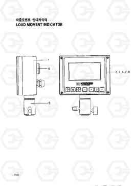
LOAD MOMENT INDICATOR гидравлического подъёмного крана колесного Hyundai HC25E
LOAD MOMENT INDICATOR гидравлического подъёмного крана колесного Hyundai HC25E со списком деталей и комплектацией. Каждую деталь можно приобрести в наличии и под заказ с дотавкой по всей России
Код подсистемы:7020
Наименование:LOAD MOMENT INDICATOR
Версия:
LOAD MOMENT INDICATOR HC25E