
User Guide
Lenovo Legion 5 Pro (16″, 7)

Read this first
Before using this documentation and the product it supports, ensure that you read and understand the
following:
• Generic Safety and Compliance Notices
• Safety and Warranty Guide
• Setup Guide
First Edition (January 2022)
© Copyright Lenovo 2022.
LIMITED AND RESTRICTED RIGHTS NOTICE: If data or software is delivered pursuant to a General Services
Administration “GSA” contract, use, reproduction, or disclosure is subject to restrictions set forth in Contract No. GS-
35F-05925.

Contents
About this guide . . . . . . . . . . . . . iii
Chapter 1. Meet your computer . . . . . 1
Front . . . . . . . . . . . . . . . . . . . . 1
Base . . . . . . . . . . . . . . . . . . . . 2
Left . . . . . . . . . . . . . . . . . . . . 3
Right . . . . . . . . . . . . . . . . . . . . 4
Rear . . . . . . . . . . . . . . . . . . . . 5
Bottom . . . . . . . . . . . . . . . . . . . 6
Features and specifications . . . . . . . . . . . 7
Statement on USB transfer rate . . . . . . . . 9
Operating environment . . . . . . . . . . . 9
Avoid constant body contact with specific hot
sections . . . . . . . . . . . . . . . . . 9
Chapter 2. Get started with your
computer . . . . . . . . . . . . . . . . 11
Work with Windows . . . . . . . . . . . . . 11
Windows help information . . . . . . . . . 11
Lenovo Vantage and Lenovo PC Manager . . . . 12
The Novo Button menu . . . . . . . . . . . . 12
Open the Novo Button menu . . . . . . . . 12
Dual-function keys. . . . . . . . . . . . . . 12
Hotkeys . . . . . . . . . . . . . . . . 13
Dual-function keys without printed icons . . . 13
The FnLock switch . . . . . . . . . . . . 14
Chapter 3. Explore your computer . . 15
Manage power . . . . . . . . . . . . . . . 15
Check the battery status . . . . . . . . . 15
Charge the battery . . . . . . . . . . . . 15
Using a Power Delivery compliant USB Type-
C charger with the computer . . . . . . . . 15
Set power button behavior. . . . . . . . . 16
A power plan . . . . . . . . . . . . . . 16
Set operation mode . . . . . . . . . . . 16
Change settings in UEFI/BIOS setup utility . . . . 16
What is UEFI/BIOS setup utility . . . . . . . 17
Open the UEFI/BIOS setup utility . . . . . . 17
Enable or disable Fool Proof Fn Ctrl . . . . . 17
Enable or disable always-on . . . . . . . . 17
Enable or disable Flip to Boot . . . . . . . 17
Set passwords in UEFI/BIOS setup utility . . . . . 17
Password types . . . . . . . . . . . . . 17
Set administrator password . . . . . . . . 18
Change or remove administrator password . . 18
Set user password . . . . . . . . . . . . 19
Enable power-on password . . . . . . . . 19
Set password for the secondary storage
device. . . . . . . . . . . . . . . . . 19
Change or remove hard disk password . . . . 20
Chapter 4. Help and support . . . . . 21
Frequently asked questions . . . . . . . . . . 21
Self-help resources . . . . . . . . . . . . . 21
What is a CRU? . . . . . . . . . . . . . . . 22
CRUs for your product model . . . . . . . . . 23
Call Lenovo . . . . . . . . . . . . . . . . 23
Before you contact Lenovo . . . . . . . . 23
Lenovo Customer Support Center . . . . . . 23
Purchase additional services. . . . . . . . . . 24
Appendix A. Notices and
trademarks . . . . . . . . . . . . . . . 25
© Copyright Lenovo 2022 i

ii User Guide
About this guide
• This guide applies to Lenovo product model(s) listed below. Illustrations in this guide may look slightly
different from your product model.
Model name Machine type (MT)
– Legion 5 Pro 16IAH7H
– Lenovo Legion 5 Pro 16IAH7H
82RF
– Legion 5 Pro 16IAH7
– Lenovo Legion 5 Pro 16IAH7
82S0
– Legion 5 Pro 16ARH7H
– Lenovo Legion 5 Pro 16ARH7H
82RG
– Legion 5 Pro 16ARH7
– Lenovo Legion 5 Pro 16ARH7
82RY
• For further compliance information, refer to the Generic Safety and Compliance Notices at https://
pcsupport.lenovo.com/docs/generic_notices.
• This guide may contain information about accessories, features, and software that are not available on all
models.
• This guide contains instructions that are based on the Windows operating system. These instructions are
not applicable if you install and use other operating systems.
• Microsoft® makes periodic feature changes to the Windows® operating system through Windows Update.
As a result, the operating system related instructions may become outdated. Refer to Microsoft resources
for the latest information.
• The content of the guide is subject to change without notice. To obtain the latest version, go to https://
support.lenovo.com.
© Copyright Lenovo 2022 iii

iv User Guide
Chapter 1. Meet your computer
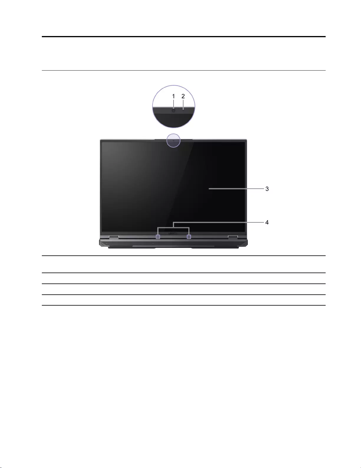
Front
1. Camera Capture still and moving images for taking photos, recording videos,
and video conferencing.
2. Camera light If the light is on, the camera is in use.
3. Screen Display text, graphics, and videos.
4. Microphones Capture or record sound and voice.
© Copyright Lenovo 2022 1
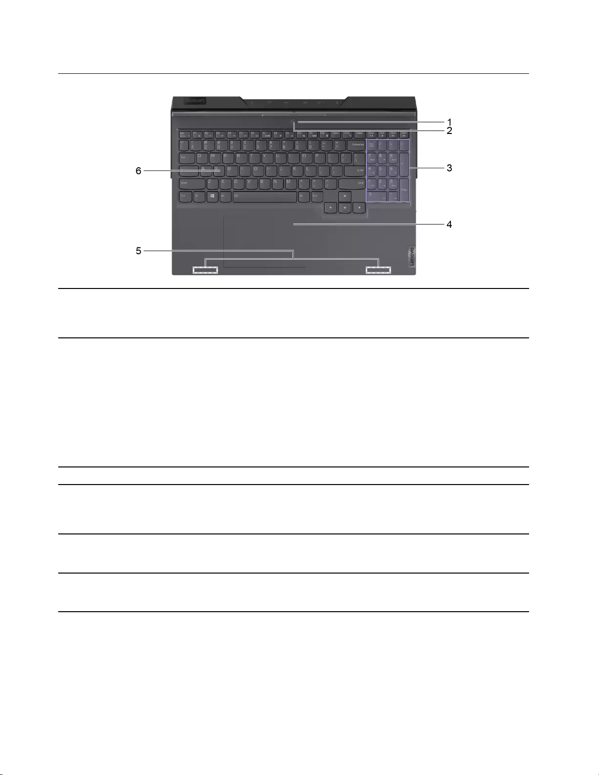
Base
1. Power button Press the button to turn on the computer or put the computer into
sleep mode.
Note: You can turn on the computer by flipping open the LCD screen
if Flip to Boot is enabled.
2. Power light Indicate the power status of the computer. The color of the power
light also reflects the currently activated operation mode. Refer to
“Set operation mode” on page 16 for how to switch operation modes.
• Solid on: The computer is turned on.
– White: in balance mode
– Red: in performance mode
– Blue: in quiet mode
• Blinking: The computer is in sleep mode.
• Off: The computer is turned off or in hibernation mode.
3. Numeric keypad To enable or disable the numeric keypad, press the Num Lock key.
4. Touchpad Perform finger touch and all the functions of a traditional mouse.
Note: The touchpad also supports multi-finger gestures. For
Windows, you can set them up in Settings ➙ Bluetooth & devices ➙
Touchpad.
5. Wireless antennas Send and receive radio waves for the built-in Wi-Fi and Bluetooth
combo adapter.
Note: The antennas are not visible from the outside of the computer.
6. Keyboard Enter characters and interact with programs.
Note: The keyboard also includes hotkeys and function keys for
changing settings and performing tasks quickly.
2User Guide
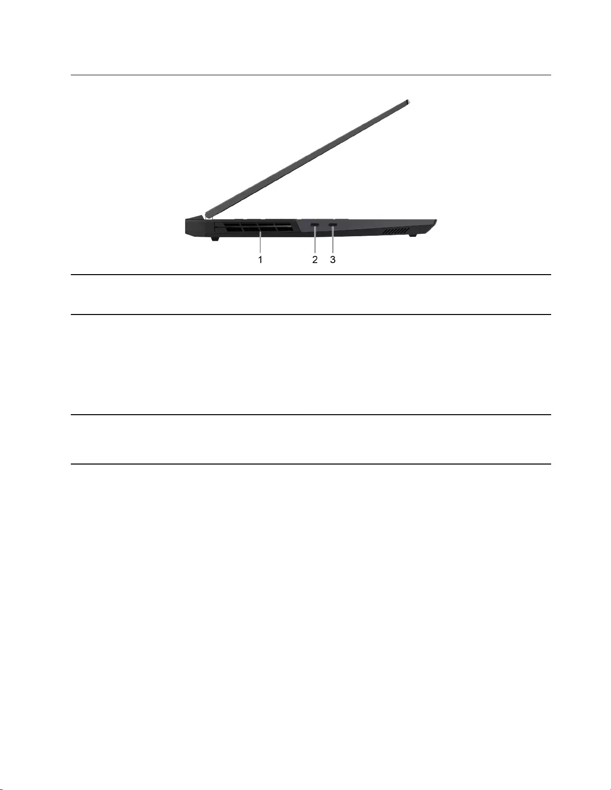
Left
1. Ventilation slots (outlet) Maintain the outgoing airflow to dissipate internal heat.
Attention: Do not block the ventilation slots. Otherwise, the
computer may overheat.
2.Thunderbolt™ 4/USB4® port This port utilizes the USB Type-C connector and can be used for:
• Connecting USB data devices.
• Connecting display devices.
• Connecting Thunderbolt-enabled docks or other devices.
Note: Your computer model includes either a Thunderbolt 4 or a
USB4 port but not both. The USB4 port can be used for connecting
Thunderbolt 3 enabled devices.
3. Multi-function USB port This port utilizes the USB Type-C connector and can be used for:
• Connecting USB data devices.
• Connecting display devices.
Chapter 1.Meet your computer 3
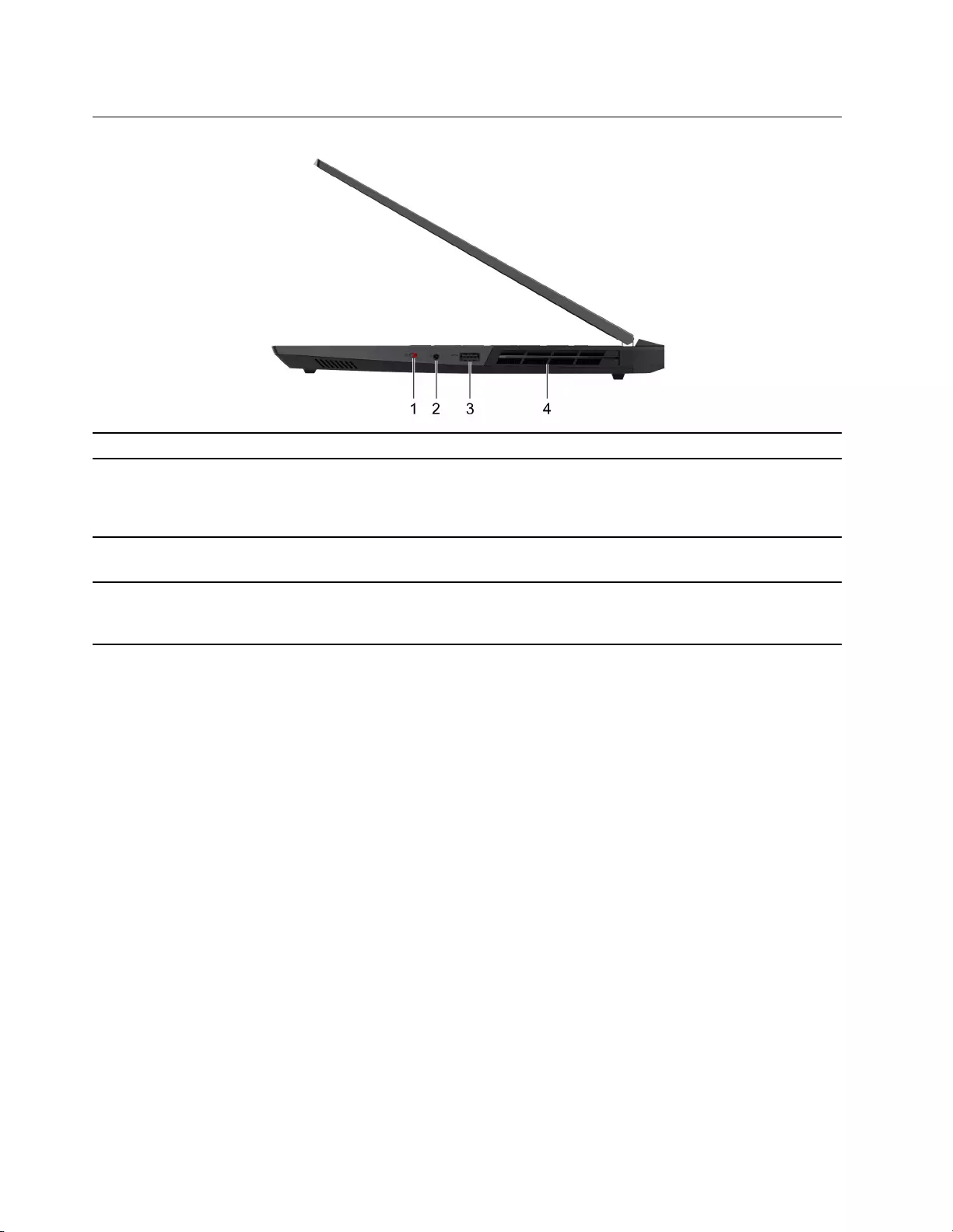
Right
1. Camera switch Disable or re-enable the camera.
2. Combo audio jack Connect to headphones or headsets with a 3.5 mm (0.14 inch), 4-pole
plug.
Note: This jack does not support standalone external microphones. If
you use headsets, choose one with a single plug.
3. USB 3.2 Gen 1 port This USB port utilizes the USB Standard-A connector. It supports
SuperSpeed USB 5 Gbps and is backwards compatible with USB 2.0.
4. Ventilation slots (outlet) Maintain the outgoing airflow to dissipate internal heat.
Attention: Do not block the ventilation slots. Otherwise, the
computer may overheat.
4User Guide
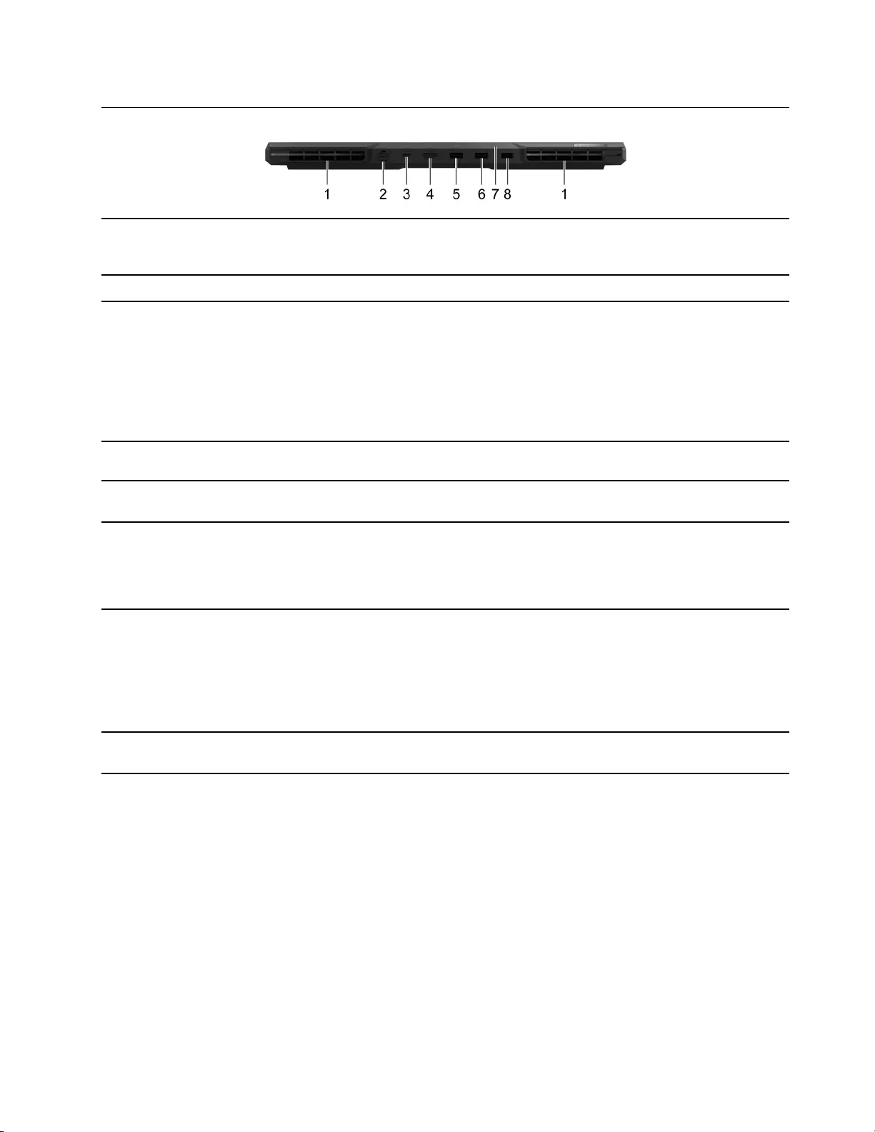
Rear
1. Ventilation slots (outlet) Maintain the outgoing airflow to dissipate internal heat.
Attention: Do not block the ventilation slots. Otherwise, the
computer may overheat.
2. Ethernet connector Connect to a local area network (LAN).
3. Multi-function USB port This port utilizes the USB Type-C connector and can be used for:
• Connecting USB data devices.
• Connecting display devices.
Note: This port also supports USB Power Delivery and can be used
as a secondary power input connector. For details, refer to “Using a
Power Delivery compliant USB Type-C charger with the computer” on
page 15.
4. HDMI™ connector Connect to a compatible digital audio device or video monitor, such
as an HDTV.
5. USB 3.2 Gen 1 port This USB port utilizes the USB Standard-A connector. It supports
SuperSpeed USB 5 Gbps and is backwards compatible with USB 2.0.
6. USB 3.2 Gen 1 port (always-on) The always-on connector can charge external devices when the
computer is turned off, in sleep or hibernation mode. The always-on
function can be turned on or off in the UEFI/BIOS setup utility.
Note: If Lenovo Vantage is pre-installed on your computer, you can
also change the always-on setting from within that software.
7. Charging light Indicate whether the computer is connected to ac power.
• Solid white: Connected to ac power; battery charge percentage
91%–100%
• Solid amber: Connected to ac power; battery charge percentage
1%–90%
• Off: Not connected to ac power
8. Power connector Connect to power with the included power cord and ac power
adapter.
Chapter 1.Meet your computer 5
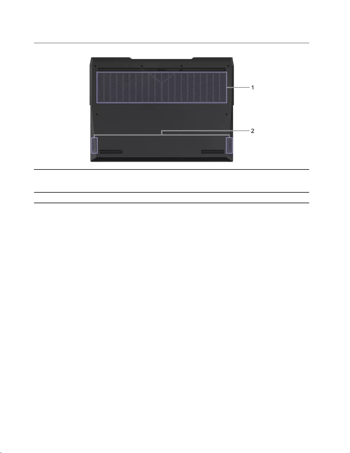
Bottom
1. Ventilation slots (inlet) Maintain the incoming airflow to dissipate internal heat.
Attention: Do not block the ventilation slots. Otherwise, the
computer might overheat.
2. Speakers Produce sound.
6User Guide

Features and specifications
Dimensions • Width: 356–360 mm
• Depth: 260–264 mm
• Thickness: 20–27 mm
ac power adapter • Input: 100 V ac–240 V ac, 50 Hz–60 Hz
• Output: 20 V dc, 15 A/20 V dc, 11.5 A
• Power: 300 W/230 W
Battery pack • Capacity: 80 Wh
• Number of cells: 4
Note: The battery capacity is the typical or average capacity as measured in a specific test
environment. Capacities measured in other environments may differ but are no lower than the
rated capacity (see product label).
Microprocessor To view the microprocessor information of your computer, right-click the Start button and then
select System.
Memory • Type: Double data rate 5 (DDR5) small outline dual in-line memory module (SODIMM)
• Number of slots: 2
Storage device • Type: solid-state drive
• Form factor: M.2 (2242 or 2280)
• Number of slots: 2
• Bus: PCI Express
Screen • Size: 16 inches
• Display resolution:
– 1920 × 1200 pixels, or
– 2560 × 1600 pixels
Keyboard • Function keys
• Hotkeys
• Numeric keypad
• Keyboard backlight
Chapter 1.Meet your computer 7

Connectors and slots • Power connector
• Combo audio jack
• HDMI 2.1 connector
• Ethernet connector
• USB Standard-A connector × 3
– Supports SuperSpeed USB 5 Gbps and backwards compatible with USB 2.0.
– Power output up to 5 V and 0.9 A
– Power output up to 5 V and 2 A (the always-on USB port)
• USB Type-C connector (rear)
– Power input up to 20 V and 6.75 A
– Power output up to 5 V and 3 A
– DisplayPort 1.4 compliant in DisplayPort Alt Mode
– Supports SuperSpeed USB 10 Gbps; backwards compatible with SuperSpeed USB 5
Gbps and USB 2.0.
• USB Type-C connector (left, Thunderbolt 4 or USB4 enabled)
– Power output up to 5 V and 3 A
– Up to 40 Gbps data transfer rate in Thunderbolt Alt Mode
– DisplayPort 1.4 compliant in DisplayPort Alt Mode
Note: This port does not support video output when the computer is working in discrete
graphics card only mode.
– Supports SuperSpeed USB 10 Gbps; backwards compatible with SuperSpeed USB 5
Gbps and USB 2.0.
• USB Type-C connector (left)
– Power output up to 5 V and 3 A
Note: If external power is supplied through the rear USB Type-C connector, the
maximum current for this connector is 0.9 A.
– DisplayPort 1.4 compliant in DisplayPort Alt Mode
– Supports SuperSpeed USB 10 Gbps; backwards compatible with SuperSpeed USB 5
Gbps and USB 2.0.
Note: Data rates and performance ratings are dependent on connected devices and cables if
they are used. USB Type-C connectors that are DisplayPort 1.4 compliant through DisplayPort
alternate mode provide maximum output resolution of 5120 x 3200, at 60 Hz frame rate and
color depth of 24 bpp (bits per pixel). The HDMI 2.1 connector supports the maximum output
resolution of 7680 x 4320, at 60 Hz frame rate, 8-bit color, and chroma subsampling of 4:2:0.
The actual maximum output resolution is dependent on the connected display device and the
cable being used.
Security features • UEFI/BIOS passwords
– Administrator password
– User password
– Master hard disk password
– User hard disk password
Wireless features • Ethernet (10/100/1000 Mbps) network adapter
• Wi-Fi and Bluetooth combo adapter
8User Guide

Statement on USB transfer rate
Depending on many factors such as the processing capability of the host and peripheral devices, file
attributes, and other factors related to system configuration and operating environments, the actual transfer
rate using the various USB connectors on this device will vary and will be slower than the data rate listed
below for each corresponding device.
USB device Data rate (Gbit/s)
3.2 Gen 1 5
3.2 Gen 2 10
Operating environment
Maximum altitude (without pressurization)
3048 m (10 000 ft)
Temperature
• At altitudes up to 2438 m (8000 ft)
– Operating: 5°C to 35°C (41°F to 95°F)
– Storage: 5°C to 43°C (41°F to 109°F)
• At altitudes above 2438 m (8000 ft)
– Maximum temperature when operating under the unpressurized condition: 31.3°C (88°F)
Note: When you charge the battery, its temperature must be no lower than 10°C (50°F).
Relative humidity
• Operating: 8% to 95% at wet-bulb temperature 23°C (73°F)
• Storage: 5% to 95% at wet-bulb temperature 27°C (81°F)
Avoid constant body contact with specific hot sections
CAUTION:
When the computer is operating, it should be placed on a hard and flat surface with its bottom area
not in contact with user’s bare skin. Under normal operating conditions, the temperature of the
bottom surface will remain within an acceptable range as defined in IEC 62368-1, but such
temperatures can still be high enough to cause discomfort or harm to the user if directly touched for
over 10 seconds at a time. As such, it is recommended that users avoid prolonged direct contact with
the bottom of the computer.
Chapter 1.Meet your computer 9

10 User Guide

Chapter 2. Get started with your computer
Work with Windows
The following table contains Windows frequently used settings. You can learn the basics and start working
with Windows right away.
To configure settings, type the corresponding keywords in the Windows search box and select the best
match. Follow the on-screen instructions to customize settings.
Table 1. Basic settings
Functions Descriptions Search by
keywords
Control Panel View or change Windows settings, including hardware and software setup
and configuration.
Control Panel
Connect to Wi-Fi
networks
For models with a wireless LAN module, you can connect your computer to
a Wi-Fi® network. Click the network icon in the Windows notification area,
and then select a network for connection.
Note: The wireless LAN module on your computer may support different
standards. For some countries or regions, use of 802.11ax may be disabled
according to local regulations.
Wi-Fi
Connect to wired
networks
For models with an Ethernet (RJ-45) connector, you can use an Ethernet
cable to connect your computer to a wired network.
—
Airplane mode Airplane mode is a convenient setting to turn all wireless communications of
your computer on and off. You may need to turn it on when boarding an
airplane.
Airplane mode
Night light mode Night light is a switch in Windows that you can turn on and off. When it is
turned on, your screen shows warmer colors and the amount of emitted
blue light is reduced. Enabling night light reduces the chances of developing
eye fatigue or eye strain.
Night light
Adjust color
temperature
If night light mode is turned on, you can adjust the color temperature of the
screen.
Note: Selected Lenovo computers are low blue light certified. These
computers are tested with night light turned on and color temperature set to
the default value of 48.
Night light
Windows
Updates
Microsoft periodically releases feature and security updates to the Windows
operating system. Updates that are applicable to your Windows version are
downloaded automatically when your computer is connected to the
Internet. When updates are downloaded, you are prompted to restart the
computer to install these updates. You can also manually check if there are
available updates for the installed version of Windows.
Attention: Only use Windows Update to download and install updates.
Updates downloaded from other sources may include security risks.
Windows Updates
Windows help information
If the on-screen instructions cannot solve your problem, refer to the following to get the online Windows help
information.
• Type Get Help or Tips in the Windows search box and then press Enter. When the app opens, type the
problem description and select the matched result.
© Copyright Lenovo 2022 11

• Visit Microsoft support Web site: https://support.microsoft.com. Enter what you are looking for in the
search box and get search results.
Lenovo Vantage and Lenovo PC Manager
They are both apps developed by Lenovo. Using either of them, you can:
• View product information and system status
• Manage and change device settings
• Check for and perform system update
Note: This feature is only available on Lenovo Vantage. In Lenovo PC Manager, you can check for and
perform driver update.
Depending on the country or region in which your computer is purchased, one of the apps may be pre-
installed on your computer. To open it, type its name in the Windows Search box and select the matched
result. If neither of the apps is pre-installed, you may install one on your own. Lenovo Vantage is available for
download free of charge from the Microsoft Store.
Note: App features are subject to change with updates and specific features may not be available on all
Lenovo products.
The Novo Button menu
The Novo Button menu can be displayed before the operating system starts. From the menu, you can
choose to
• Open the BIOS/UEFI setup utility
• Open the boot device selection menu
• Open the Windows startup options screen
Note: From the Windows startup options screen, you can then choose to
Start your computer using a recovery drive
Reset your computer
Open advanced options screen
Open the Novo Button menu
Step 1. Turn on or restart the computer.
Step 2. Press F9 repeatedly.
Dual-function keys
Some keys on the keyboard are dual-function keys. Each of such keys can provide two functions: the
primary function and the secondary function. Most dual-function keys are located in the top row of the
keyboard though several letter keys and the Space key are also dual-function keys.
The primary function of a dual-function key is accessed by pressing the key directly and the secondary
function is accessed by pressing the key while holding down the Fn key.
Note: The Fn key is located in the lower left corner on a Lenovo keyboard.
12 User Guide
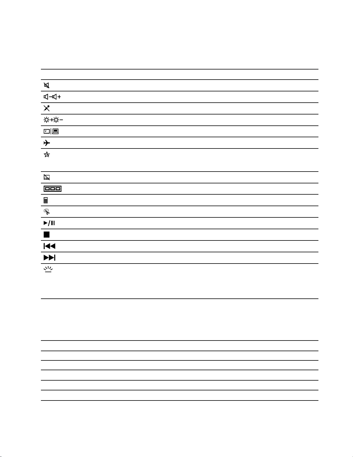
Hotkeys
Hotkeys are dual-function keys with an icon printed on the key. The icons indicate the hidden functions of the
hotkeys. To use the hidden function, hold down the Fn key.
Hotkey Function
Mute/Unmute sound.
Decrease/Increase system volume.
Mute/Unmute the microphone.
Increase/Decrease screen brightness.
Switch display devices.
Turn airplane mode on and off.
Display an app launcher for quick access to Lenovo apps and services.
Note: For some models, you may need to connect to the Internet and complete
system update for this function to take effect.
Enable/Disable the touchpad.
Display thumbnails of all open apps.
Open the Windows Calculator app.
Open the Windows Snipping tool.
Play or pause playback of media.
Stop playback of media.
Go to the previous media file in the playlist or folder.
Go the next media file in the playlist or folder.
Turn on/off or adjust the brightness of the keyboard backlight.
Note: This hotkey must always be used while holding down the Fn key. Selected
models include a keyboard with multi-color backlight. For such a keyboard, this
hotkey switches among several predefined lighting patterns. Lighting patterns are
customizable in Lenovo Vantage or Legion Zone.
Dual-function keys without printed icons
Some dual-function keys share keys with letter keys and numeric keys. Such keys do not have a dedicated
printed icon. The following table lists the secondary functions for these keys.
Key combination Hidden function
Fn + B Break
Fn + P Pause
Fn + S SysRq
Fn + K ScrLk
Fn + Q Switch operation modes
Chapter 2.Get started with your computer 13

The FnLock switch
The FnLock is a switch that reverses the primary and secondary functions of top-row dual-function keys. The
FnLock switch shares the ESC key (in the upper left corner of the keyboard). To turn it on or off, press Fn +
ESC. The following table provides an example of how the FnLock switch changes the default function of the
F1 key.
FnLock FnLock light Primary function of the F1 key
Off Off F1 function *
On On Mute/Unmute sound
* The F1 function is application-dependent. It may have no function if the active application does not have a
definition for the key.
14 User Guide

Chapter 3. Explore your computer
Manage power
Use the information in this section to achieve the best balance between performance and power efficiency.
Check the battery status
The battery status icon or is in the Windows notification area. You can check the battery status, view
the current power plan, and access battery settings quickly.
Click the battery status icon to display the percentage of battery power remaining and change the power
mode. A warning message is displayed when the battery is low.
Charge the battery
When the remaining battery power is low, charge your battery by connecting your computer to ac power.
The battery is fully charged in about two to four hours. The actual charging time depends on the battery
capacity, the physical environment, and whether you are using the computer.
Battery charging is also affected by its temperature. The recommended temperature range for charging the
battery is between 10°C (50°F) and 35°C (95°F).
Note:
You can check the battery temperature in Lenovo Vantage or Lenovo PC Manager.
To maximize the life of the battery, once the battery is fully charged, it must discharge to 94% or lower
before it will be allowed to recharge again.
Using a Power Delivery compliant USB Type-C charger with the
computer
The USB Type-C connector on the rear of the computer conforms to USB Power Delivery Specification. If
you did not carry the included ac power adapter with your computer, you have the option of using a qualified
USB Type-C charger (purchased separately) that is also Power Delivery compliant to charge the computer in
sleep or powered-off state. Lenovo branded USB Type-C chargers with the following listed maximum ratings
are tested to work with the computer. Chargers of other brands with the same ratings should also work but
are not thoroughly tested.
• 20 V, 3.25 A
• 20 V, 4.75 A
• 20 V, 5 A
• 20 V, 6.75 A
The rear USB Type-C connector is not designed as the primary power input connector. When the computer
is operating, the power supplied by the USB Type-C charger may be insufficient. As a result, the computer
may not operate at its full capacity and the battery charging may stop or is very slow. Use the included ac
power adapter whenever possible.
CAUTION:
When purchasing third-party USB Type-C chargers for use with the computer, choose a product that
is safety approved or certified. A disqualified charger may cause damage to your computer or pose an
© Copyright Lenovo 2022 15

electrical hazard. In many countries and regions, manufacturers or importers of electric chargers can
submit their products to a certification authority or approved and recognized testing laboratories.
Such a product usually carries a mark if it was tested to pass relevant quality and safety standards.
For some countries and regions, this certification process is even mandatory. If you live in mainland
China, choose a charger with the “CCC” mark; for users in many European countries, choose one with
the “CE” mark; for users in the United States and Canada, choose a Listed charger that carries a mark
by one of the Nationally Recognized Testing Laboratories. (For example, the “UL Listed”mark). For
people living in other countries and regions, consult a qualified electrical engineer for how to select a
safety approved electric charger.
Set power button behavior
By default, pressing the power button puts the computer to sleep mode. However, you can change the
power button behavior in Windows Control Panel.
Step 1. Type Control Panel in the Windows search box and then press Enter. Open the control panel and
view by large or small icons.
Step 2. Select the power options and then click choose what the power button does.
A power plan
A power plan is a collection of power-saving settings made available by an operating system. With a power
plan, you can set idle time-outs for different hardware components to enter a low-power state. The default
power plan and some of its idle time-out settings are listed below for computer models pre-installed with
Windows.
The listed settings are active when the computer is connected to an electrical outlet. If your computer include
a built-in battery pack, a different collection of time-out settings is set to take effect when the computer is
operating on battery power.
Power settings 82RF, 82S0 82RG, 82RY
Power plan Balanced Balanced
Turn off the display After 10 minutes After 10 minutes
Put the computer to sleep After 30 minutes After 10 minutes
Note: To wake the computer from the sleep state, press the power button or any key on the keyboard.
Change or customize a power plan
This operation is applicable to computers with pre-installed Windows.
Step 1. Type power plan in the Windows search box and then press Enter.
Step 2. Customize a power plan of your preference.
Set operation mode
Your computer can work in different operation modes. The performance and power consumption of the
computer vary in different operation modes. Press Fn + Q to cycle through different operation modes.
Note: Performance mode is not available when your computer runs on battery power.
Change settings in UEFI/BIOS setup utility
This section introduces what is UEFI/BIOS and the operations you can perform in its setup utility.
16 User Guide

What is UEFI/BIOS setup utility
UEFI/BIOS is the first program that runs when a computer starts. UEFI/BIOS initializes hardware components
and loads the operating system and other programs. Your computer may include a setup program (setup
utility) with which you can change certain UEFI/BIOS settings.
Open the UEFI/BIOS setup utility
Step 1. Turn on or restart the computer.
Step 2. Press F2 repeatedly.
Step 3. On the welcome screen, select More Settings.
Enable or disable Fool Proof Fn Ctrl
Step 1. Open the UEFI/BIOS setup utility.
Step 2. Select Configuration.
Step 3. Change the Fool Proof Fn Ctrl setting to Enabled or Disabled.
Step 4. Select Exit ➙ Exit Saving Changes.
When enabled, the Fn key and the Ctrl key can be used interchangeably for key combinations involving the
Ctrl key. For example, you can press either Ctrl + A or Fn + A to select all text in a text editing application.
Enable or disable always-on
For some Lenovo computers with always-on connectors, the always-on function can be enabled or disabled
in the UEFI/BIOS setup utility.
Step 1. Open the UEFI/BIOS setup utility.
Step 2. Select Configuration ➙ Always On USB and press Enter.
Step 3. Change the setting to Disabled or Enabled.
Step 4. Select Exit ➙ Exit Saving Changes.
Enable or disable Flip to Boot
When Flip to Boot is enabled, you can turn on the computer by flipping open the screen.
Step 1. Open the UEFI/BIOS setup utility.
Step 2. Select Configuration.
Step 3. Change the setting for Flip to Boot.
Note: You may also set Flip to Boot in Lenovo Vantage or Lenovo PC Manager.
Set passwords in UEFI/BIOS setup utility
This section introduces the types of passwords that you can set in the UEFI (Unified Extensible Firmware
Interface) or BIOS (Basic Input/Output System) setup utility.
Password types
You can set various types of passwords in the UEFI/BIOS setup utility.
Chapter 3.Explore your computer 17

Password type Pre-requisite Usage
Administrator password No You must enter it to start the setup
utility.
User password The administrator password must be
set.
You can use the user password to
start the setup utility.
Master hard disk password No You must enter it to start the
operating system.
User hard disk password The master hard disk password must
be set.
You can use the user hard disk
password to start the operating
system.
Notes:
• All passwords set in the setup utility consist of alphanumeric characters only.
• If you start the setup utility using the user password, you can only change a few settings.
Set administrator password
You set the administrator password to prevent unauthorized access to the UEFI/BIOS setup utility.
Attention: If you forget the administrator password, a Lenovo authorized service personnel cannot reset
your password. You must take your computer to a Lenovo authorized service personnel to have the system
board replaced. Proof of purchase is required and a fee will be charged for parts and service.
Step 1. Open the UEFI/BIOS setup utility.
Step 2. Select Security ➙ Set Administrator Password and press Enter.
Step 3. Enter a password string that contains only letters and numbers and then press Enter
Step 4. Enter the password again and press Enter.
Step 5. Select Exit ➙ Exit Saving Changes.
Next time you start the computer, you must enter the administrator password to open the setup utility. If
Power on Password is enabled, you must enter the administrator password or the user password to start
the computer.
Change or remove administrator password
Only the administrator can change or remove the administrator password.
Step 1. Open the UEFI/BIOS setup utility using the administrator password.
Step 2. Select Security ➙ Set Administrator Password and press Enter.
Step 3. Enter the current password.
Step 4. In the Enter New Password text box, enter the new password.
Step 5. In the Confirm New Password text box, enter the new password again.
Note: If you want to remove the password, press Enter in both text boxes without entering any
character.
Step 6. Select Exit ➙ Exit Saving Changes.
If you remove the administrator password, the user password is also removed.
18 User Guide

Set user password
You must set the administrator password before you can set the user password.
The administrator of the setup utility might need to set a user password for use by others.
Step 1. Open the UEFI/BIOS setup utility using the administrator password.
Step 2. Select Security ➙ Set User Password and press Enter.
Step 3. Enter a password string that contains only letters and numbers and then press Enter. The user
password must be different from the administrator password.
Step 4. Enter the password again and press Enter.
Step 5. Select Exit ➙ Exit Saving Changes.
Enable power-on password
If the administrator password has been set, you can enable power-on password to enforce greater security.
Step 1. Open the UEFI/BIOS setup utility.
Step 2. Select Security ➙ Power on Password and press Enter.
Note: The administrator password must be set in advance.
Step 3. Change the setting to Enabled.
Step 4. Select Exit ➙ Exit Saving Changes.
If power-on password is enabled, a prompt appears on the screen every time you turn on the computer. You
must enter the administrator or user password to start the computer.
Set password for the secondary storage device
Permanent data is stored on secondary storage devices. Your computer may include one or more solid-state
drive or hard disk drive as secondary storage device(s). You can set passwords for secondary storage
devices in the setup utility to prevent unauthorized access to your data.
Attention: Be extremely careful when setting a hard disk password. If you forget the hard disk password, a
Lenovo authorized service personnel cannot reset your password or recover data from the hard disk. You
must take your computer to a Lenovo authorized service personnel to have the hard disk drive replaced.
Proof of purchase is required and a fee will be charged for parts and service.
Step 1. Open the UEFI/BIOS setup utility.
Step 2. Select Security ➙ Set Hard Disk Password and press Enter.
Note: If your computer model includes more than one secondary storage device, you can set
separate password for each device. If you start the setup utility using the user password, you
cannot set hard disk password.
Step 3. Follow on-screen instructions to set both master and user passwords.
Note: The master and user hard disk passwords must be set at the same time.
Step 4. Select Exit ➙ Exit Saving Changes.
If the hard disk password is set, you must provide the correct password to start the operating system.
Chapter 3.Explore your computer 19

Change or remove hard disk password
Step 1. Open the UEFI/BIOS setup utility.
Step 2. Select Security.
Step 3. Change or remove the hard disk password.
To change or remove master password, select Change Master Password and press Enter.
Note: If you remove the master hard disk password, the user hard disk password is also removed.
To change user password, select Change User Password and press Enter.
Note: The user hard disk password cannot be removed separately.
Step 4. Select Exit ➙ Exit Saving Changes.
20 User Guide

Chapter 4. Help and support
Frequently asked questions
How do I partition my storage
drive? Refer to https://support.lenovo.com/solutions/ht503851
What should I do if my computer
stops responding.
Press and hold the power button until the computer turns off. Then restart the
computer.
What should I do if I spill liquid on
the computer?
1. Carefully unplug the ac power adapter and turn off the computer immediately.
The more quickly you stop the current from passing through the computer the
more likely you will reduce damage from short circuits.
Attention: Although you might lose some data or work by turning off the
computer immediately, leaving the computer on might make your computer
unusable.
2. Wait until you are certain that all the liquid is dry before turning on your
computer.
CAUTION:
Do not try to drain out the liquid by turning over the computer. If your
computer has keyboard drainage holes on the bottom, the liquid will be
drained out through the holes.
Where can I get the latest device
drivers and UEFI/BIOS?
• Lenovo Vantage or Lenovo PC Manager
• Lenovo Support Web site at https://support.lenovo.com
Self-help resources
Use the following self-help resources to learn more about the computer and troubleshoot problems.
Resources How to access?
Troubleshooting and frequently asked questions • https://www.lenovo.com/tips
• https://forums.lenovo.com
Accessibility information https://www.lenovo.com/accessibility
Reset or restore Windows
• Use Lenovo recovery options.
1. Go to https://support.lenovo.com/
HowToCreateLenovoRecovery.
2. Follow the on-screen instructions.
• Use Windows recovery options.
1. Go to https://pcsupport.lenovo.com.
2. Detect your computer or manually select your
computer model.
3. Click Diagnostics ➙ Operating System
Diagnostics and then follow the on-screen
instructions.
© Copyright Lenovo 2022 21

Resources How to access?
Use Lenovo Vantage or Lenovo PC Manager to:
• Download and install the latest drivers and firmware.
• Configure hardware settings
• Diagnose computer hardware problems.
• Check the computer warranty status.
Use Windows Search.
Product documentation:
• Generic Safety and Compliance Notices
• Safety and Warranty Guide
• Setup Guide
• This User Guide
• Regulatory Notice
1. Go to https://support.lenovo.com.
2. Detect your computer or select computer model
manually.
3. Select Documentation and filter out the
documentation you want.
Lenovo Support Web site with the latest support
information of the following:
• Drivers and software
• Diagnostic solutions
• Product and service warranty
• Product and parts details
• Knowledge base and frequently asked questions
Visit https://support.lenovo.com
Windows help information
• Use Get Help or Tips.
• Use Windows Search or the Cortana® personal
assistant.
• Microsoft support Web site: https://
support.microsoft.com
What is a CRU?
Customer replaceable units (CRUs) are parts that can be upgraded or replaced by the customer. A Lenovo
computer may contain the following types of CRUs:
Self-service CRU Parts that can be installed or replaced easily by
customer themselves or by trained service
technicians at an additional cost.
Optional-service CRU Parts that can be installed or replaced by customers
with a greater skill level. Trained service technicians
can also provide service to install or replace the
parts under the type of warranty designated for the
customer’s machine.
If you intend to install a CRU, Lenovo will ship the CRU to you. You might be required to return the defective
part that is replaced by the CRU. When return is required: (1) return instructions, a prepaid shipping label,
and a container will be included with the replacement CRU; and (2) you might be charged for the
replacement CRU if Lenovo does not receive the defective CRU within thirty (30) days of your receipt of the
replacement CRU. For full details, see the Lenovo Limited Warranty at https://www.lenovo.com/warranty/llw_
02.
22 User Guide

CRUs for your product model
The table below lists the CRUs and CRU types that are defined for your product model.
Part Self-service CRU Optional-service CRU
Power cord X
ac power adapter X
Notes:
• CRU replacement instruction is provided in one or more of the following publications and are available
from Lenovo at any time upon your request.
the product User Guide
the printed publications that came with the product
• Replacement of any parts not listed above, including the built-in rechargeable battery, must be done by a
Lenovo-authorized repair facility or technician. Go to https://support.lenovo.com/partnerlocation for more
information.
Call Lenovo
If you have tried to correct the problem yourself and still need help, you can call Lenovo Customer Support
Center.
Before you contact Lenovo
Record product information and problem details before you contact Lenovo.
Product information Problem symptoms and details
• Product name
• Machine type and serial number
• What is the problem? Is it continuous or intermittent?
• Any error message or error code?
• What operating system are you using? Which version?
• Which software applications were running at the time
of the problem?
• Can the problem be reproduced? If so, how?
Note: The product name and serial number can usually be found on the bottom of the computer, either
printed on a label or etched on the cover.
Lenovo Customer Support Center
During the warranty period, you can call Lenovo Customer Support Center for help.
Telephone numbers
For a list of the Lenovo Support phone numbers for your country or region, go to https://
pcsupport.lenovo.com/supportphonelist.
Note: Phone numbers are subject to change without notice. If the number for your country or region is not
provided, contact your Lenovo reseller or Lenovo marketing representative.
Chapter 4.Help and support 23

Services available during the warranty period
• Problem determination — Trained personnel are available to assist you with determining if you have a
hardware problem and deciding what action is necessary to fix the problem.
• Lenovo hardware repair — If the problem is determined to be caused by Lenovo hardware under warranty,
trained service personnel are available to provide the applicable level of service.
• Engineering change management — Occasionally, there might be changes that are required after a product
has been sold. Lenovo or your reseller, if authorized by Lenovo, will make selected Engineering Changes
(ECs) that apply to your hardware available.
Services not covered
• Replacement or use of parts not manufactured for or by Lenovo or nonwarranted parts
• Identification of software problem sources
• Configuration of UEFI/BIOS as part of an installation or upgrade
• Changes, modifications, or upgrades to device drivers
• Installation and maintenance of network operating systems (NOS)
• Installation and maintenance of programs
For the terms and conditions of the Lenovo Limited Warranty that apply to your Lenovo hardware product,
see “Warranty information” in the Safety and Warranty Guide that comes with your computer.
Purchase additional services
During and after the warranty period, you can purchase additional services from Lenovo at https://
pcsupport.lenovo.com/warrantyupgrade.
Service availability and service name might vary by country or region.
24 User Guide

Appendix A. Notices and trademarks
Notices
Lenovo may not offer the products, services, or features discussed in this document in all countries. Consult
your local Lenovo representative for information on the products and services currently available in your
area. Any reference to a Lenovo product, program, or service is not intended to state or imply that only that
Lenovo product, program, or service may be used. Any functionally equivalent product, program, or service
that does not infringe any Lenovo intellectual property right may be used instead. However, it is the user’s
responsibility to evaluate and verify the operation of any other product, program, or service.
Lenovo may have patents or pending patent programs covering subject matter described in this document.
The furnishing of this document does not give you any license to these patents. You can send license
inquiries, in writing, to:
Lenovo (United States), Inc.
8001 Development Drive
Morrisville, NC 27560
U.S.A.
Attention: Lenovo Director of Licensing
LENOVO PROVIDES THIS PUBLICATION «AS IS» WITHOUT WARRANTY OF ANY KIND, EITHER EXPRESS
OR IMPLIED, INCLUDING, BUT NOT LIMITED TO, THE IMPLIED WARRANTIES OF NON-INFRINGEMENT,
MERCHANTABILITY OR FITNESS FOR A PARTICULAR PURPOSE. Some jurisdictions do not allow
disclaimer of express or implied warranties in certain transactions, therefore, this statement may not apply to
you.
Changes are made periodically to the information herein; these changes will be incorporated in new editions
of the publication. To provide better service, Lenovo reserves the right to improve and/or modify the
products and software programs described in the manuals included with your computer, and the content of
the manual, at any time without additional notice.
The software interface and function and hardware configuration described in the manuals included with your
computer might not match exactly the actual configuration of the computer that you purchase. For the
configuration of the product, refer to the related contract (if any) or product packing list, or consult the
distributor for the product sales. Lenovo may use or distribute any of the information you supply in any way it
believes appropriate without incurring any obligation to you.
The products described in this document are not intended for use in implantation or other life support
applications where malfunction may result in injury or death to persons. The information contained in this
document does not affect or change Lenovo product specifications or warranties. Nothing in this document
shall operate as an express or implied license or indemnity under the intellectual property rights of Lenovo or
third parties. All information contained in this document was obtained in specific environments and is
presented as an illustration. The result obtained in other operating environments may vary.
Lenovo may use or distribute any of the information you supply in any way it believes appropriate without
incurring any obligation to you.
Any references in this publication to non-Lenovo Web sites are provided for convenience only and do not in
any manner serve as an endorsement of those Web sites. The materials at those Web sites are not part of the
materials for this Lenovo product, and use of those Web sites is at your own risk.
© Copyright Lenovo 2022 25

Any performance data contained herein was determined in a controlled environment. Therefore, the result
obtained in other operating environments may vary significantly. Some measurements may have been made
on development-level systems and there is no guarantee that these measurements will be the same on
generally available systems. Furthermore, some measurements may have been estimated through
extrapolation. Actual results may vary. Users of this document should verify the applicable data for their
specific environment.
This document is copyrighted by Lenovo and is not covered by any open source license, including any Linux
agreement(s) which may accompany software included with this product. Lenovo may update this document
at any time without notice.
For the latest information or any questions or comments, contact or visit the Lenovo Web site:
https://support.lenovo.com
Trademarks
Lenovo, the Lenovo logo and Lenovo Legion are trademarks of Lenovo. Thunderbolt is a trademark of Intel
Corporation or its subsidiaries. Microsoft, Windows, OneDrive, Outlook, Skype, Office 365 and Cortana are
trademarks of the Microsoft group of companies. DisplayPort is a trademark of the Video Electronics
Standards Association. The terms HDMI and HDMI High-Definition Multimedia Interface, and the HDMI logo
are trademarks or registered trademarks of HDMI Licensing Administrator, Inc. in the United States and other
countries. Wi-Fi is a registered trademark of Wi-Fi Alliance. USB Type-C and USB4 are registered
trademarks of USB Implementers Forum. All other trademarks are the property of their respective owners.
26 User Guide
Hardware Maintenance Manual
Lenovo Legion 5 (15, 7)
First Edition (January 2022)
Copyright Lenovo 2022.
Contents
About this manual . . . . . . . . . . . . iii
Chapter 1. Safety information . . . . . . 1 General safety . . . . . . . . . . . . . . . . 1 Electrical safety . . . . . . . . . . . . . . . . 1 Safety inspection guide . . . . . . . . . . . . . 2 Handling devices that are sensitive to electrostatic discharge . . . . . . . . . . . . . . . . . . 3 Grounding requirements . . . . . . . . . . . . 4 Safety notices (multilingual translations) . . . . . . 4
Chapter 2. General checkout . . . . . 21 What to do first . . . . . . . . . . . . . . . 21 CRU list . . . . . . . . . . . . . . . . . . 22
Chapter 3. Identifying FRUs (CRUs) . . . . . . . . . . . . . . . . . 23 Locate FRUs and CRUs . . . . . . . . . . . 23
Chapter 4. Removing a FRU or CRU . . . . . . . . . . . . . . . . . . 29 Service tools . . . . . . . . . . . . . . . . 29 General guidelines. . . . . . . . . . . . . . 29 Remove the lower case . . . . . . . . . . . . 30 Remove the solid-state drive (SSD) plate (L) . . . . 31 Remove the solid-state drive (SSD) plate (R). . . . 32 Remove the solid-state drive (SSD) . . . . . . . 33 Remove the solid-state drive (SSD) stand off . . . 34 Remove the battery pack (Legion 5 15IAH7H, Legion 5 15IAH7) . . . . . . . . . . . . . . 34 Remove the battery pack (Legion 5 15ARH7H, Legion 5 15ARH7) . . . . . . . . . . . . . . 35
Remove the touchpad board cable . . . . . . . 36 Remove the speakers . . . . . . . . . . . . 36 Remove the Wi-Fi card . . . . . . . . . . . . 37 Remove the memory module . . . . . . . . . 38 Remove the DC-in bracket . . . . . . . . . . 39 Remove the thermal module . . . . . . . . . . 39 Remove the CMOS battery . . . . . . . . . . 40 Remove the I/O board . . . . . . . . . . . . 41 Remove the system board and the I/O board cable . . . . . . . . . . . . . . . . . . . 42
Use a Golden Key U1 tool to flash-write key id information . . . . . . . . . . . . . . . 44
Remove the strip cover . . . . . . . . . . . . 44 Remove the LCD module . . . . . . . . . . . 45 Remove the upper case (with touchpad, keyboard, waterproof breath film and antenna cables) . . . . 46 Disassemble the LCD module . . . . . . . . . 47
Remove the LCD bezel . . . . . . . . . . 47 Remove the hinge cover. . . . . . . . . . 47 Remove the LCD panel . . . . . . . . . . 48 Remove the EDP cable . . . . . . . . . . 49 Remove the sensor board . . . . . . . . . 50 Remove the camera bracket and camera cable . . . . . . . . . . . . . . . . . 51 Remove the microphone rubber. . . . . . . 52 Remove the camera board. . . . . . . . . 53 Remove the LCD cover . . . . . . . . . . 53
Appendix A. Label locations. . . . . . 55 Trademarks . . . . . . . . . . . . . . . . lvii
Copyright Lenovo 2022 i
ii Hardware Maintenance Manual
About this manual
This manual contains service and reference information for the following Lenovo products.
Model name Machine type (MT)
Legion 5 15IAH7H 82RB
Lenovo Legion 5 15IAH7H
Legion 5 15IAH7 82RC
Lenovo Legion 5 15IAH7
Legion 5 15ARH7H 82RD
Lenovo Legion 5 15ARH7H
Legion 5 15ARH7 82RE
Lenovo Legion 5 15ARH7
Important:
This manual is intended only for trained service technicians who are familiar with Lenovo products.
Before servicing a Lenovo product, be sure to read all the information under Chapter 1 Safety information on page 1.
Copyright Lenovo 2022 iii
iv Hardware Maintenance Manual
Chapter 1. Safety information
This chapter presents the following safety information that you need to be familiar with before you service a Lenovo notebook computer.
General safety Follow these rules to ensure general safety: Observe good housekeeping in the area of the machines during and after maintenance. When lifting any heavy object:
1. Make sure that you can stand safely without slipping.
2. Distribute the weight of the object equally between your feet.
3. Use a slow lifting force. Never move suddenly or twist when you attempt to lift.
4. Lift by standing or by pushing up with your leg muscles; this action removes the strain from the muscles in your back. Do not attempt to lift any object that weighs more than 16 kg (35 lb) or that you think is too heavy for you.
Do not perform any action that causes hazards to the customer, or that makes the equipment unsafe. Before you start the machine, make sure that other service technicians and the customer’s personnel are
not in a hazardous position. Place removed covers and other parts in a safe place, away from all personnel, while you are servicing the
machine. Keep your tool case away from walk areas so that other people will not trip over it. Do not wear loose clothing that can be trapped in the moving parts of a machine. Make sure that your
sleeves are fastened or rolled up above your elbows. If your hair is long, fasten it. Insert the ends of your necktie or scarf inside clothing or fasten it with a non-conductive clip, about 8
centimeters (3 inches) from the end. Do not wear jewelry, chains, metal-frame eyeglasses, or metal fasteners for your clothing.
Attention: Metal objects are good electrical conductors. Wear safety glasses when you are hammering, drilling, soldering, cutting wire, attaching springs, using
solvents, or working in any other conditions that might be hazardous to your eyes. After service, reinstall all safety shields, guards, labels, and ground wires. Replace any safety device that
is worn or defective. Reinstall all covers correctly before returning the machine to the customer. Fan louvers on the machine help to prevent overheating of internal components. Do not obstruct fan
louvers or cover them with labels or stickers.
Electrical safety Observe the following rules when working on electrical equipment.
Important: Use only approved tools and test equipment. Some hand tools have handles covered with a soft material that does not insulate you when working with live electrical currents.Many customers have, near their equipment, rubber floor mats that contain small conductive fibers to decrease electrostatic discharges. Do not use this type of mat to protect yourself from electrical shock. Find the room emergency power-off (EPO) switch, disconnecting switch, or electrical outlet. If an electrical
accident occurs, you can then operate the switch or unplug the power cord quickly. Do not work alone under hazardous conditions or near equipment that has hazardous voltages. Disconnect all power before:
Performing a mechanical inspection Working near power supplies
Copyright Lenovo 2022 1
Removing or installing main units Before you start to work on the machine, unplug the power cord. If you cannot unplug it, ask the customer
to power-off the wall box that supplies power to the machine, and to lock the wall box in the off position. If you need to work on a machine that has exposed electrical circuits, observe the following precautions:
Ensure that another person, familiar with the power-off controls, is near you.
Attention: Another person must be there to switch off the power, if necessary. Use only one hand when working with powered-on electrical equipment; keep the other hand in your
pocket or behind your back.
Attention: An electrical shock can occur only when there is a complete circuit. By observing the above rule, you may prevent a current from passing through your body.
When using testers, set the controls correctly and use the approved probe leads and accessories for that tester.
Stand on suitable rubber mats (obtained locally, if necessary) to insulate you from grounds such as metal floor strips and machine frames.
Observe the special safety precautions when you work with very high voltages; Instructions for these precautions are in the safety sections of maintenance information. Use extreme care when measuring high voltages.
Regularly inspect and maintain your electrical hand tools for safe operational condition. Do not use worn or broken tools and testers. Never assume that power has been disconnected from a circuit. First, check that it has been powered off. Always look carefully for possible hazards in your work area. Examples of these hazards are moist floors,
non-grounded power extension cables, power surges, and missing safety grounds. Do not touch live electrical circuits with the reflective surface of a plastic dental mirror. The surface is
conductive; such touching can cause personal injury and machine damage. Do not service the following parts with the power on when they are removed from their normal operating
places in a machine: Power supply units Pumps Blowers and fans Motor generators Similar units as listed above This practice ensures correct grounding of the units.
If an electrical accident occurs: Use caution; do not become a victim yourself. Switch off power. Send another person to get medical aid.
Safety inspection guide The purpose of this inspection guide is to assist you in identifying potentially unsafe conditions. As each machine was designed and built, required safety items were installed to protect users and service technicians from injury. This guide addresses only those items. You should use good judgment to identify potential safety hazards due to attachment of non-Lenovo features or options not covered by this inspection guide.
If any unsafe conditions are present, you must determine how serious the apparent hazard could be and whether you can continue without first correcting the problem.
Consider these conditions and the safety hazards they present: Electrical hazards, especially primary power (primary voltage on the frame can cause serious or fatal
electrical shock) Explosive hazards, such as a damaged cathode ray tube (CRT) face or a bulging capacitor Mechanical hazards, such as loose or missing hardware
2 Hardware Maintenance Manual
To determine whether there are any potentially unsafe conditions, use the following checklist at the beginning of every service task. Begin the checks with the power off, and the power cord disconnected.
Checklist:
1. Check exterior covers for damage (loose, broken, or sharp edges). 2. Power off the computer. Disconnect the power cord. 3. Check the power cord for:
a. A third-wire ground connector in good condition. Use a meter to measure third-wire ground continuity for 0.1 ohm or less between the external ground pin and the frame ground.
b. The power cord should be the authorized type specified for your computer. Go to: http:// www.lenovo.com/serviceparts-lookup
c. Insulation must not be frayed or worn. 4. Check for cracked or bulging batteries.
5. Remove the cover. 6. Check for any obvious non-Lenovo alterations. Use good judgment as to the safety of any non-Lenovo
alterations.
7. Check inside the unit for any obvious unsafe conditions, such as metal filings, contamination, water or other liquids, or signs of fire or smoke damage.
8. Check for worn, frayed, or pinched cables. 9. Check that the power-supply cover fasteners (screws or rivets) have not been removed or tampered
with.
Handling devices that are sensitive to electrostatic discharge Any computer part containing transistors or integrated circuits (ICs) should be considered sensitive to electrostatic discharge (ESD). ESD damage can occur when there is a difference in charge between objects. Protect against ESD damage by equalizing the charge so that the machine, the part, the work mat, and the person handling the part are all at the same charge.
Notes: 1. Use product-specific ESD procedures when they exceed the requirements noted here. 2. Make sure that the ESD protective devices you use have been certified (ISO 9000) as fully effective.
When handling ESD-sensitive parts: Keep the parts in protective packages until they are inserted into the product. Avoid contact with other people. Wear a grounded wrist strap against your skin to eliminate static on your body. Prevent the part from touching your clothing. Most clothing is insulative and retains a charge even when
you are wearing a wrist strap. Use a grounded work mat to provide a static-free work surface. The mat is especially useful when
handling ESD-sensitive devices. Select a grounding system, such as those listed below, to provide protection that meets the specific
service requirement.
Note: The use of a grounding system to guard against ESD damage is desirable but not necessary. Attach the ESD ground clip to any frame ground, ground braid, or green-wire ground. When working on a double-insulated or battery-operated system, use an ESD common ground or
reference point. You can use coax or connector-outside shells on these systems. Use the round ground prong of the ac plug on ac-operated computers.
Chapter 1. Safety information 3
Grounding requirements Electrical grounding of the computer is required for operator safety and correct system function. Proper grounding of the electrical outlet can be verified by a certified electrician.
Safety notices (multilingual translations) The safety notices in this section are provided in the following languages: English Arabic Brazilian Portuguese French German Hebrew Japanese Korean Spanish Traditional Chinese
DANGER
DANGER
DANGER
4 Hardware Maintenance Manual
DANGER
DANGER
DANGER
DANGER
DANGER
Chapter 1. Safety information 5
6 Hardware Maintenance Manual
PERIGO
PERIGO
PERIGO
Chapter 1. Safety information 7
PERIGO
PERIGO
PERIGO
PERIGO
PERIGO
8 Hardware Maintenance Manual
DANGER
DANGER
DANGER
DANGER
Chapter 1. Safety information 9
DANGER
DANGER
DANGER
DANGER
VORSICHT
10 Hardware Maintenance Manual
VORSICHT
VORSICHT
VORSICHT
VORSICHT
Chapter 1. Safety information 11
VORSICHT
VORSICHT
VORSICHT
12 Hardware Maintenance Manual
Chapter 1. Safety information 13
14 Hardware Maintenance Manual
Chapter 1. Safety information 15
16 Hardware Maintenance Manual
Chapter 1. Safety information 17
18 Hardware Maintenance Manual
Chapter 1. Safety information 19
20 Hardware Maintenance Manual
Chapter 2. General checkout
This chapter contains the following topics:
Before you go to the checkout instructions, ensure that you read the following important notes.
Important notes:
Only certified trained personnel should service the computer.
Before replacing any FRU, read the entire page on removing and replacing FRUs.
Be extremely careful during such write operations as copying, saving, or formatting. Drives in the computer that you are servicing sequence might have been altered. If you select an incorrect drive, data or programs might be overwritten.
Replace an FRU only with another FRU of the correct model. When you replace an FRU, make sure that the model of the machine and the FRU part number are correct by referring to the FRU parts list.
An FRU should not be replaced because of a single, unreproducible failure. Single failures can occur for a variety of reasons that have nothing to do with a hardware defect, such as cosmic radiation, electrostatic discharge, or software errors. Consider replacing an FRU only when a problem recurs. If you suspect that an FRU is defective, clear the error log and run the test again. If the error does not recur, do not replace the FRU.
Be careful not to replace a nondefective FRU.
What to do first When you return an FRU, you must include the following information in the parts exchange form or parts return form that you attach to it:
1. Name and phone number of service technician 2. Date of service
3. Date on which the machine failed 4. Date of purchase 5. Failure symptoms, error codes appearing on the display, and beep symptoms
6. Procedure index and page number in which the failing FRU was detected 7. Failing FRU name and part number 8. Machine type, model number, and serial number 9. Customer’s name and address
Note: During the warranty period, the customer may be responsible for repair costs if the computer damage was caused by misuse, accident, modification, unsuitable physical or operating environment, or improper maintenance by the customer. Following is a list of some common items that are not covered under warranty and some symptoms that might indicate that the system was subjected to stress beyond normal use.
Before checking problems with the computer, determine whether the damage is covered under the warranty by referring to the following list:
The following are not covered under warranty: LCD panel cracked from the application of excessive force or from being dropped Scratched (cosmetic) parts Distortion, deformation, or discoloration of the cosmetic parts Plastic parts, latches, pins, or connectors that have been cracked or broken by excessive force Damage caused by liquid spilled into the system
Copyright Lenovo 2022 21
Damage caused by the improper insertion of a personal-computer card (PC card) or the installation of an incompatible card
Improper disc insertion or use of an external optical drive Fuses blown by attachment of a non-supported device Forgotten computer password (making the computer unusable) Sticky keys caused by spilling a liquid onto the keyboard Use of an incorrect ac power adapter on laptop products
The following symptoms might indicate damage caused by non-warranted activities: Missing parts might be a symptom of unauthorized service or modification. Check for obvious damage to a hard disk drive. If the spindle of a hard disk drive becomes noisy, the hard
disk drive might have been dropped or subject to excessive force.
CRU list Table 1. Models: All
CRU Type
ac power adapter self-service
Power cord self-service
22 Hardware Maintenance Manual
Chapter 3. Identifying FRUs (CRUs)
Locate FRUs and CRUs The exploded illustrations help Lenovo service technicians identify FRUs or CRUs that they may need to replace when servicing a customers computer.
Copyright Lenovo 2022 23
Figure 1. Exploded view
24 Hardware Maintenance Manual
Table 2. FRU (CRU) categories
No. FRU (CRU) category
1 LCD module Note: The LCD module as a whole is not an FRU, it contains FRUs as its components.
2 Strip cover
3 Upper case (with touchpad, keyboard, waterproof breath film and antenna cables)
4 DC-in bracket
5 System board
6 Bracket
7 I/O board cable
8 I/O board
9 2242 Solid-state drive (SSD)
10 2280 Solid-state drive (SSD)
11 Solid-state drive (SSD) standoff
12 Thermal module
13 Speakers
14 Battery sponge
15 Battery pack
16 Solid-state drive (SSD) plate (R)
17 Lower case
18 Solid-state drive (SSD) plate (L)
19 CMOS battery
20 Memory module shielding
21 Memory module
22 Wi-Fi card
23 Touchpad board cable
a Power cord
b ac power adapter
c Screw kit
Chapter 3. Identifying FRUs (CRUs) 25
Figure 2. LCD module — exploded view
26 Hardware Maintenance Manual
Table 3. FRU categories for the LCD module
No. FRU (CRU) category
1 LCD bezel
2 Hinge cover
3 LCD panel
4 EDP cable
5 Removable tape
6 Camera bracket
7 Microphone rubber
8 Camera board
9 Camera cable
10 Tape
11 Sensor board
12 LCD cover
Chapter 3. Identifying FRUs (CRUs) 27
28 Hardware Maintenance Manual
Chapter 4. Removing a FRU or CRU
Service tools The following table lists tools for servicing Lenovo computers. Tools with a cross mark are needed for serving the product models as described by this publication. Prepare them before you service the product.
Table 4. Service tools
Service tool and consumable Model applicability
Screw driver (Phillips head) (PH1/PH01) X
Screw driver (Torx head) (T5)
Screw driver (Torx head) (T30)
Pry tool 1 X
Tweezers (conductive) X
Tweezers (isolated)
Suction cup
Hexagonal socket
Silicone grease
Acetate tape X
Polyamide tape
Mylar tape
Electrical tape
Double-sided tape
Conductive tape
Eraser
Heat gun
Brown brush
Notes:
T30 screw drivers are used to service the new Intel Xeon CPUs.
Hexagonal sockets are used to remove antenna connectors.
Silicone grease is applied to the CPU and heatsink surfaces to eliminate air gaps.
General guidelines When removing or replacing an FRU, ensure that you observe the following general guidelines:
1. Do not try to service any computer unless you have been trained and certified. An untrained person runs the risk of damaging parts.
2. Begin by removing any FRUs that have to be removed before replacing the failing FRU. Any such FRUs are listed at the beginning of each FRU replacement procedure. Remove them in the order in which they are listed.
Copyright Lenovo 2022 29
3. Follow the correct sequence in the steps for removing an FRU, as shown in the illustrations by the numbers in square callouts.
4. When removing an FRU, move it in the direction as shown by the arrow in the illustration.
5. To install a new FRU in place, perform the removal procedure in reverse and follow any notes that pertain to replacement.
6. When replacing an FRU, carefully retain and reuse all screws.
7. When replacing the base cover, reapply all labels that come with the replacement base cover. If some original labels are not included with the replacement base cover, peal them off from the original base cover and paste them on the replacement base cover.
DANGER
Before removing any FRU or CRU, shut down the computer and unplug all power cords from electrical outlets.
Attention: After replacing an FRU, do not turn on the computer until you have ensured that all screws, springs, and other small parts are in place and none are loose inside the computer. Verify this by shaking the computer gently and listening for rattling sounds. Metallic parts or metal flakes can cause electrical short circuits.
Attention: The system board is sensitive to and can be damaged by ESD. Before touching it, establish personal grounding by touching a ground point with one hand or by using an ESD strap (P/N 6405959).
Remove the lower case Make sure the computer has been shut down before servicing the computer.
Step 1. Place the computer upside down on a flat surface.
Step 2. Remove ten screws.
Figure 3. Remove ten screws
Screw specifications Number of screws
M2 x L11.8 6
M2 x L4 4
30 Hardware Maintenance Manual
Step 3. Pry up the latches and then remove the lower case.
Figure 4. Pry up the latches and remove the lower case
Go to https://support.lenovo.com/partslookup to look up the Lenovo part number of the following replacement part:
Lower case
Remove the solid-state drive (SSD) plate (L) Make sure the following FRU (or CRU) has been removed.
Remove the lower case on page 30
Step 1. Disconnect the battery pack cable from the system board.
Attention: Use your fingernails to pull the connector to unplug it. Do not pull the cable.
Figure 5. Disconnect the battery pack cable from the system board
Step 2. Remove three screws and then remove the SSD plate (L) carefully.
Chapter 4. Removing a FRU or CRU 31
Figure 6. Remove the SSD plate (L)
Screw specifications Number of screws
M2 x L4.5 3
Go to https://support.lenovo.com/partslookup to look up the Lenovo part number of the following replacement part:
Solid-state drive (SSD) plate (L)
Remove the solid-state drive (SSD) plate (R) Make sure the following FRU (or CRU) has been removed.
Remove the lower case on page 30
Step 1. Disconnect the battery pack cable from the system board.
Attention: Use your fingernails to pull the connector to unplug it. Do not pull the cable.
Step 2. Remove three screws and then remove the SSD plate (R) carefully.
Figure 7. Remove the SSD plate (R)
Screw specifications Number of screws
M2 x L4.5 3
32 Hardware Maintenance Manual
Go to https://support.lenovo.com/partslookup to look up the Lenovo part number of the following replacement part:
Solid-state drive (SSD) plate (R)
Remove the solid-state drive (SSD) Make sure the following FRUs (or CRUs) have been removed.
Remove the lower case on page 30
Remove the solid-state drive (SSD) plate (L) on page 31
Remove the solid-state drive (SSD) plate (R) on page 32
Step 1. Remove two screws.
Figure 8. Remove two screws
Screw specifications Number of screws
M2 x L1.8 2
Step 2. Remove the SSD by pulling it away from the slot.
Figure 9. Remove the SSD
Go to https://support.lenovo.com/partslookup to look up the Lenovo part number of the following replacement part:
Solid-state drive (SSD)
Chapter 4. Removing a FRU or CRU 33
Remove the solid-state drive (SSD) stand off Make sure the following FRUs (or CRUs) have been removed.
Remove the lower case on page 30
Remove the solid-state drive (SSD) plate (L) on page 31
Remove the solid-state drive (SSD) plate (R) on page 32
Remove the solid-state drive (SSD) on page 33
Step 1. Remove the SSD stand off.
Figure 10. Remove the SSD stand off
Go to https://support.lenovo.com/partslookup to look up the Lenovo part number of the following replacement part:
SSD stand off
Remove the battery pack (Legion 5 15IAH7H, Legion 5 15IAH7) Make sure the following FRUs (or CRUs) have been removed.
Remove the lower case on page 30
Remove the solid-state drive (SSD) plate (L) on page 31
Remove the solid-state drive (SSD) plate (R) on page 32
Step 1. Remove one SSD besides the CMOS battery, see Remove the solid-state drive (SSD) on page 33 for details.
Step 2. Remove six screws and then remove the battery pack.
Note: Attach the battery sponge to the battery pack when replacing the battery pack.
34 Hardware Maintenance Manual
Figure 11. Remove six screws and remove the battery pack
Screw specifications Number of screws
M2 x L4.5 6
Go to https://support.lenovo.com/partslookup to look up the Lenovo part numbers of the following replacement parts:
Battery pack
battery sponge
Remove the battery pack (Legion 5 15ARH7H, Legion 5 15ARH7) Make sure the following FRUs (or CRUs) have been removed.
Remove the lower case on page 30
Remove the solid-state drive (SSD) plate (R) on page 32
Step 1. Remove one SSD besides the Wi-Fi card, see Remove the solid-state drive (SSD) on page 33 for details.
Step 2. Remove four screws and then remove the battery pack.
Note: Attach the battery sponge to the battery pack when replacing the battery pack.
Figure 12. Remove four screws and remove the battery pack
Chapter 4. Removing a FRU or CRU 35
Screw specifications Number of screws
M2 x L4.5 4
Go to https://support.lenovo.com/partslookup to look up the Lenovo part numbers of the following replacement parts:
Battery pack
battery sponge
Remove the touchpad board cable Make sure the following FRUs (or CRUs) have been removed.
Remove the lower case on page 30
Remove the solid-state drive (SSD) plate (L) on page 31
Remove the solid-state drive (SSD) plate (R) on page 32
Remove the battery pack (Legion 5 15IAH7H, Legion 5 15IAH7) on page 34
Step 1. Disconnect the touchpad board cable from the system board and the touchpad board. Remove the touchpad board cable.
Figure 13. Remove the touchpad board cable
Go to https://support.lenovo.com/partslookup to look up the Lenovo part number of the following replacement part:
Touchpad board cable
Remove the speakers Make sure the following FRUs (CRUs) have been removed.
Remove the lower case on page 30
Remove the solid-state drive (SSD) plate (L) on page 31
Remove the solid-state drive (SSD) plate (R) on page 32
Remove the battery pack (Legion 5 15IAH7H, Legion 5 15IAH7) on page 34
36 Hardware Maintenance Manual
Step 1. Disconnect the speaker cable from the system board and release the speaker cable from the cable guide. Remove the speakers.
Figure 14. Remove the speakers
Go to https://support.lenovo.com/partslookup to look up the Lenovo part number of the following replacement part:
Speakers
Remove the Wi-Fi card Make sure the following FRU (or CRU) has been removed.
Remove the lower case on page 30
Remove the solid-state drive (SSD) plate (R) on page 32
Step 1. Detach the main and auxiliary antenna cable connectors. Remove one screw and then remove the Wi-Fi card by pulling it away from the slot.
Figure 15. Remove the Wi-Fi card
Screw specifications Number of screws
M2 x L1.8 1
Go to https://support.lenovo.com/partslookup to look up the Lenovo part number of the following replacement part:
Chapter 4. Removing a FRU or CRU 37
Wi-Fi card
Remove the memory module Make sure the following FRU (or CRU) has been removed.
Remove the lower case on page 30
Step 1. Disconnect the battery pack cable from the system board.
Attention: Use your fingernails to pull the connector to unplug it. Do not pull the cable.
Step 2. Remove the memory module shielding.
Figure 16. Remove the memory module shielding
Step 3. Release the two latches on both edges of the socket at the same time. Then, remove the memory module.
Figure 17. Remove the memory module
Go to https://support.lenovo.com/partslookup to look up the Lenovo part numbers of the following replacement parts:
Memory module
Memory module shielding
38 Hardware Maintenance Manual
Remove the DC-in bracket Make sure the following FRU (or CRU) has been removed.
Remove the lower case on page 30
Step 1. Disconnect the battery pack cable from the system board.
Attention: Use your fingernails to pull the connector to unplug it. Do not pull the cable.
Step 2. Remove two screws and then remove the DC-in bracket.
Figure 18. Remove two screws and then remove the DC-in bracket
Screw specifications Number of screws
M2 x L6.0 2
Go to https://support.lenovo.com/partslookup to look up the Lenovo part number of the following replacement part:
DC-in bracket
Remove the thermal module Make sure the following FRUs (or CRUs) have been removed.
Remove the lower case on page 30
Remove the solid-state drive (SSD) plate (L) on page 31
Remove the solid-state drive (SSD) plate (R) on page 32
Step 1. Detach the thermal module cable connectors and then remove four screws.
Chapter 4. Removing a FRU or CRU 39
Figure 19. Detach the thermal module cable connectors and remove four screws
Screw specifications Number of screws
M2 x L4.5 2
M2.5 x L7 2
Step 2. Loosen six screws and then remove the thermal module.
Figure 20. Loosen six screws and remove the thermal module
Go to https://support.lenovo.com/partslookup to look up the Lenovo part number of the following replacement part:
Thermal module
Remove the CMOS battery Make sure the following FRUs (or CRUs) have been removed.
Remove the lower case on page 30
Remove the solid-state drive (SSD) plate (L) on page 31
Remove the solid-state drive (SSD) plate (R) on page 32
Remove the thermal module on page 39
40 Hardware Maintenance Manual
Step 1. Detach the CMOS battery cable connector and then remove the CMOS battery.
Figure 21. Remove the CMOS battery
Go to https://support.lenovo.com/partslookup to look up the Lenovo part number of the following replacement part:
CMOS battery
Remove the I/O board Make sure the following FRUs (or CRUs) have been removed.
Remove the lower case on page 30
Remove the solid-state drive (SSD) plate (L) on page 31
Remove the solid-state drive (SSD) plate (R) on page 32
Remove the thermal module on page 39
Step 1. Disconnect the I/O board cable from the I/O board and then remove the I/O board.
Figure 22. Remove the I/O board
Chapter 4. Removing a FRU or CRU 41
Go to https://support.lenovo.com/partslookup to look up the Lenovo part number of the following replacement part:
I/O board
Remove the system board and the I/O board cable Make sure the following FRUs (or CRUs) have been removed.
Remove the lower case on page 30
Remove the solid-state drive (SSD) plate (L) on page 31
Remove the solid-state drive (SSD) plate (R) on page 32
Remove the solid-state drive (SSD) on page 33
Remove the solid-state drive (SSD) stand off on page 34
Remove the battery pack (Legion 5 15IAH7H, Legion 5 15IAH7) on page 34
Remove the Wi-Fi card on page 37
Remove the memory module on page 38
Remove the DC-in bracket on page 39
Remove the thermal module on page 39
Remove the CMOS battery on page 40
Step 1. Disconnect cables connected to the system board.
Figure 23. Disconnect cables connected to the system board
Step 2. Remove five screws and then lift the system board carefully.
42 Hardware Maintenance Manual
Figure 24. Remove five screws and lift the system board
Screw specifications Number of screws
M2 x L4.5 5
Step 3. Turn over the system board. Disconnect the cable connected to the system board and then remove the system board with the I/O board cable.
Figure 25. Remove the system board with the I/O board cable
Step 4. Separate the I/O board cable from the system board.
Figure 26. Separate the I/O board cable from the system board
Go to https://support.lenovo.com/partslookup to look up the Lenovo part numbers of the following replacement parts:
System board
I/O board cable
Chapter 4. Removing a FRU or CRU 43
Use a Golden Key U1 tool to flash-write key id information After replacing the system board and re-assembling the computer, use a pre-made Golden Key U1 tool to start the computer and flash-write the serial number (SN), machine type (MT), product name (PN), and UUID to the new system board.
The Golden Key U1 tool is prepared by running the U1 Update software on a FAT32-formatted USB thumb drive. Go to http://support.lenovo.com/us/en/solutions/HT506954 for detailed instructions on how to create and use a Golden Key U1 tool.
Remove the strip cover Make sure the following FRUs (or CRUs) have been removed.
Remove the lower case on page 30
Remove the solid-state drive (SSD) plate (L) on page 31
Remove the solid-state drive (SSD) plate (R) on page 32
Remove the solid-state drive (SSD) on page 33
Remove the solid-state drive (SSD) stand off on page 34
Remove the battery pack (Legion 5 15IAH7H, Legion 5 15IAH7) on page 34
Remove the solid-state drive (SSD) plate (R) on page 32
Remove the system board and the I/O board cable on page 42
Step 1. Remove two screws and open the latches.
Figure 27. Remove two screws and open the latches
Screw specifications Number of screws
M2 x L8 2
Step 2. Remove the strip cover.
44 Hardware Maintenance Manual
Figure 28. Remove the strip cover
Go to https://support.lenovo.com/partslookup to look up the Lenovo part number of the following replacement part:
Strip cover
Remove the LCD module Make sure the following FRUs (CRUs) have been removed.
Remove the lower case on page 30
Remove the solid-state drive (SSD) plate (L) on page 31
Remove the solid-state drive (SSD) plate (R) on page 32
Remove the thermal module on page 39
Remove the strip cover on page 44
Step 1. Disconnect the EDP cable from the system board and then remove four screws.
Figure 29. Disconnect the EDP cable from the system board and remove four screws
Screw specifications Number of screws
M2 x L3 2
M2.5 x L7 2
Chapter 4. Removing a FRU or CRU 45
Step 2. Remove two screws and then lift the LCD module carefully.
Figure 30. Remove two screws and lift the LCD module
Screw specifications Number of screws
M2.5 x L7 2
Step 3. Take out the EDP cable and then remove the LCD module.
Figure 31. Take out the EDP cable and then remove the LCD module
Remove the upper case (with touchpad, keyboard, waterproof breath film and antenna cables) Make sure the following FRUs (CRUs) have been removed.
Remove the lower case on page 30
Remove the solid-state drive (SSD) plate (L) on page 31
Remove the solid-state drive (SSD) plate (R) on page 32
Remove the solid-state drive (SSD) on page 33
Remove the solid-state drive (SSD) stand off on page 34
Remove the battery pack (Legion 5 15IAH7H, Legion 5 15IAH7) on page 34
Remove the touchpad board cable on page 36
Remove the speakers on page 36
46 Hardware Maintenance Manual
Remove the Wi-Fi card on page 37
Remove the memory module on page 38
Remove the DC-in bracket on page 39
Remove the thermal module on page 39
Remove the CMOS battery on page 40
Remove the I/O board on page 41
Remove the system board and the I/O board cable on page 42
Remove the strip cover on page 44
Remove the LCD module on page 45
Go to https://support.lenovo.com/partslookup to look up the Lenovo part number of the following replacement part:
Upper case (with touchpad, keyboard, waterproof breath film and antenna cables)
Disassemble the LCD module The LCD module as a whole is not an FRU. Instead, it contains FRUs as its components. Before disassembling the LCD module, make sure it has been detached from the upper case.
Remove the LCD bezel Make sure the following unit has been removed.
Remove the LCD module on page 45
Step 1. Remove the LCD bezel.
Figure 32. Remove the LCD bezel
Go to https://support.lenovo.com/partslookup to look up the Lenovo part number of the following replacement part:
LCD bezel
Remove the hinge cover Make sure the following FRUs (or CRUs) have been removed.
Remove the LCD module on page 45
Remove the LCD bezel on page 47
Chapter 4. Removing a FRU or CRU 47
Step 1. Remove the hinge cover.
Figure 33. Remove the hinge cover
Go to https://support.lenovo.com/partslookup to look up the Lenovo part number of the following replacement part:
Hinge cover
Remove the LCD panel Make sure the following FRUs (CRUs) have been removed.
Remove the LCD module on page 45
Remove the LCD bezel on page 47
Remove the hinge cover on page 47
Step 1. Remove six screws and then remove the hinge.
Figure 34. Remove the hinge
Screw specifications Number of screws
M2.5 x L2.5 6
Step 2. Remove the two pieces of removable tape with tweezers.
Note: The removable tape is not reusable. Replace it when replacing related FRUs.
48 Hardware Maintenance Manual
Figure 35. Remove the two pieces of removable tape
Step 3. Lift the LCD panel slightly. Peel off the tape and then disconnect the EDP cable from the LCD panel and then remove the LCD panel.
Figure 36. Disconnect the EDP cable and remove the LCD panel
Go to https://support.lenovo.com/partslookup to look up the Lenovo part numbers of the following replacement parts:
LCD panel
Removable tape
Remove the EDP cable Make sure the following FRUs (CRUs) have been removed.
Remove the LCD module on page 45
Remove the LCD bezel on page 47
Remove the hinge cover on page 47
Remove the LCD panel on page 48
Step 1. Disconnect the EDP cable from the sensor board. Release the EDP cable and then remove the EDP cable.
Chapter 4. Removing a FRU or CRU 49
Figure 37. Remove the EDP cable
Go to https://support.lenovo.com/partslookup to look up the Lenovo part numbers of the following replacement parts:
EDP cable
Removable tape
Remove the sensor board Make sure the following FRUs (CRUs) have been removed.
Remove the LCD module on page 45
Remove the LCD bezel on page 47
Remove the hinge cover on page 47
Remove the LCD panel on page 48
Step 1. Peel off the tape.
Figure 38. Peel off the tape
Step 2. Disconnect cables connected to the sensor board and then remove the sensor board.
50 Hardware Maintenance Manual
Figure 39. Remove the sensor board
Go to https://support.lenovo.com/partslookup to look up the Lenovo part numbers of the following replacement parts:
Tape
Sensor board
Removable tape
Remove the camera bracket and camera cable Make sure the following FRUs (CRUs) have been removed.
Remove the LCD module on page 45
Remove the LCD bezel on page 47
Remove the hinge cover on page 47
Remove the LCD panel on page 48
Step 1. Remove two screws and then remove the camera bracket.
Figure 40. Remove two screws and remove the camera bracket
Screw specifications Number of screws
M1.6 x L2.4 2
Step 2. Disconnect the camera cable from the sensor board and the camera board. Remove the camera cable.
Chapter 4. Removing a FRU or CRU 51
Figure 41. Remove the camera cable
Go to https://support.lenovo.com/partslookup to look up the Lenovo part numbers of the following replacement parts:
Camera cable
Camera bracket
Removable tape
Remove the microphone rubber Make sure the following FRUs (CRUs) have been removed.
Remove the LCD module on page 45
Remove the LCD bezel on page 47
Remove the hinge cover on page 47
Remove the LCD panel on page 48
Step 1. Remove the camera bracket, see Remove the camera bracket and camera cable on page 51 for details.
Step 2. Remove the microphone rubber.
Figure 42. Remove the microphone rubber
52 Hardware Maintenance Manual
Go to https://support.lenovo.com/partslookup to look up the Lenovo part numbers of the following replacement parts:
Microphone rubber
Removable tape
Remove the camera board Make sure the following FRUs (CRUs) have been removed.
Remove the LCD module on page 45
Remove the LCD bezel on page 47
Remove the LCD panel on page 48
Remove the microphone rubber on page 52
Step 1. Disconnect camera cable from the camera board and then remove the camera board.
Figure 43. Remove the camera board
Go to https://support.lenovo.com/partslookup to look up the Lenovo part numbers of the following replacement parts:
Camera board
Removable tape
Remove the LCD cover Make sure the following FRUs (CRUs) have been removed.
Remove the LCD module on page 45
Remove the LCD bezel on page 47
Remove the hinge cover on page 47
Remove the LCD panel on page 48
Remove the EDP cable on page 49
Remove the sensor board on page 50
Remove the camera bracket and camera cable on page 51
Chapter 4. Removing a FRU or CRU 53
Remove the microphone rubber on page 52
Remove the camera board on page 53
Go to https://support.lenovo.com/partslookup to look up the Lenovo part number of the following replacement part:
LCD cover
54 Hardware Maintenance Manual
Appendix A. Label locations
Figure 44. Label layout on the back side of the base cover
Labels attached to the base cover are country/region specific. Make sure to apply the appropriate labels to the replacement base cover.
Table 5. All base cover labels
Label Label name Applied country/region Label dimensions
a Rating label India 33 mm x 24 mm
WW 66 mm x 24 mm
PRC 33 mm x 24 mm
b Rating print label 43 mm x 24 mm
c OS label 16 mm x 22.5 mm
d WL/BT label Brazil 16.5 mm x 15 mm
TW 32 mm x 10 mm
Israel 32 mm x 10 mm
South Africa 20 mm x 10 mm
Morocco 10 mm x 10 mm
Indonesia 15 mm x 10 mm
Belarus 40 mm x 8 mm
Argentina 32 mm x 10 mm
e Country label Korea (print) 50 mm x 16 mm
Copyright Lenovo 2022 55
Table 5. All base cover labels (continued)
f TW vision warning label 70 mm x 10 mm
g Indonesia label 26 mm x 10 mm
h Vietnam energy label 10 mm x 9 mm
I Argentina 68 mm x 6 mm
j Malaysia MCMC label 8 mm x 8 mm
k BIS 22 mm x 30 mm
56 Hardware Maintenance Manual
Trademarks LENOVO and the LENOVO logo are trademarks of Lenovo.
All other trademarks a
| Document’s Content and Additional Information | Share Manual |
|---|---|
|
Lenovo Legion 5 Pro Operation & user’s manual
Pages Preview: Document Transcription:
See Details |


Lenovo Legion 5 Pro — мощный игровой ноутбук, который может стать отличным решением для любителей компьютерных игр. Однако, чтобы в полной мере насладиться всеми возможностями этого устройства, необходимо правильно настроить его. В данном подробном руководстве мы рассмотрим основные шаги по настройке ноутбука Lenovo Legion 5 Pro, чтобы обеспечить его оптимальную работу. Будут рассмотрены такие аспекты, как настройка операционной системы, установка драйверов, настройка графики и многое другое.
Первым шагом после приобретения ноутбука Lenovo Legion 5 Pro следует настроить операционную систему. Установите все необходимые обновления, чтобы обеспечить полную совместимость и безопасность работы вашего устройства. Не забудьте настроить параметры конфиденциальности и безопасности, чтобы защитить свои данные.
Далее важно установить все необходимые драйверы для ноутбука Lenovo Legion 5 Pro. Посетите официальный сайт Lenovo и загрузите актуальные драйверы для своей модели ноутбука. Установите драйверы для графической карты, звука, сетевых устройств и прочих компонентов. Это позволит вам полностью использовать все функции вашего устройства и обеспечить стабильную работу системы.
После установки драйверов не забудьте отрегулировать настройки графики. В ноутбуке Lenovo Legion 5 Pro установлена мощная графическая карта, которая может выдавать великолепную картинку в играх. Откройте настройки графической карты и настройте разрешение экрана, частоту обновления и другие параметры под свои предпочтения.
Важно помнить, что правильная настройка ноутбука Lenovo Legion 5 Pro позволит вам обеспечить оптимальную производительность и использовать все возможности этого мощного игрового устройства. Следуйте нашему подробному руководству и настройте свой ноутбук по своему вкусу!
Содержание
- Как настроить ноутбук Lenovo Legion 5 Pro
- Подготовка к настройке ноутбука
- Установка операционной системы
- Настройка системы и программного обеспечения
- Оптимизация работы ноутбука для игр
Как настроить ноутбук Lenovo Legion 5 Pro
Настройка ноутбука Lenovo Legion 5 Pro включает несколько этапов, которые позволят вам получить максимальную производительность и комфорт при использовании устройства.
1. Обновление операционной системы.
Первым делом стоит убедиться, что ваша операционная система имеет все последние обновления. Для этого зайдите в настройки и проверьте наличие обновлений. Обновление операционной системы позволит исправить ошибки, улучшить безопасность устройства и повысить его производительность.
2. Установка драйверов.
Для оптимальной работы ноутбука необходимо установить все драйверы, предоставляемые производителем. Это позволит полноценно использовать все возможности вашего устройства. Перейдите на официальный сайт Lenovo, найдите свою модель ноутбука и скачайте все необходимые драйверы. Установите их последовательно, следуя инструкциям на экране.
3. Настройка энергосбережения.
Настройка энергосбережения может помочь вам продлить время автономной работы ноутбука. В зависимости от ваших потребностей, вы можете выбрать режимы баланса или экономии энергии. Найдите соответствующие настройки в панели управления или в специальной программе энергосбережения, предоставляемой производителем.
4. Оптимизация производительности.
Чтобы получить максимальную производительность от вашего ноутбука, рекомендуется произвести его оптимизацию. Отключите все неиспользуемые программы и службы, которые запускаются при старте системы. Удалите ненужные приложения и файлы, освободив тем самым оперативную память и диск. Также стоит обратить внимание на настройки графики, чтобы использовать все возможности видеокарты.
Важно помнить, что настройка ноутбука Lenovo Legion 5 Pro может быть индивидуальной и зависит от ваших предпочтений и потребностей. Эти рекомендации являются основными и могут быть дополнены вами в соответствии с ваши задачами.
Подготовка к настройке ноутбука
Перед началом настройки ноутбука Lenovo Legion 5 Pro рекомендуется выполнить несколько важных шагов, чтобы обеспечить оптимальную работу устройства.
1. Распакуйте ноутбук и проверьте его комплектацию. Убедитесь, что в комплекте есть все необходимые аксессуары, такие как зарядное устройство и документация.
2. Подключите зарядное устройство к ноутбуку и подключите его к электрической розетке. Убедитесь, что ноутбук заряжается.
3. Включите ноутбук, нажав кнопку питания. Дождитесь загрузки операционной системы.
4. Произведите первоначальную настройку языка и региональных параметров. Следуйте инструкциям на экране и выберите соответствующие параметры.
5. Подключите ноутбук к интернету. Вы можете использовать проводное или беспроводное подключение.
6. Выполните обновление операционной системы и установите все необходимые обновления и патчи безопасности.
7. Создайте резервные копии важных данных. Это позволит защитить вашу информацию в случае потери или повреждения ноутбука.
8. Установите и настройте антивирусное программное обеспечение для защиты от вирусов и других угроз.
9. Ознакомьтесь с документацией и инструкциями по использованию ноутбука. Это поможет вам изучить особенности устройства и настроек.
10. Проверьте работу всех устройств и портов ноутбука, таких как клавиатура, тачпад, USB-порты и т.д.
После завершения этих шагов вы будете готовы к началу настройки ноутбука Lenovo Legion 5 Pro и более продуктивной работе с устройством.
Установка операционной системы
Перед началом использования ноутбука Lenovo Legion 5 Pro необходимо установить операционную систему. Вместе с ноутбуком будет поставляться предустановленная операционная система, но если вы хотите использовать другую операционную систему или выполнить чистую установку, вам потребуется выполнять следующие шаги:
- Изначально, подключите ноутбук к электрической розетке или подключите его к источнику питания с помощью адаптера переменного тока.
- Включите ноутбук, нажав кнопку питания.
- Когда появится логотип Lenovo, нажмите сочетание клавиш, чтобы войти в BIOS. Обычно это клавиша F2 или Delete, но производитель может указать иные клавиши.
- Внутри BIOS найдите раздел «Boot» (загрузка) и выберите стратегию загрузки, позволяющую использовать установочный носитель операционной системы. Обычно это USB или DVD диск.
- Вставьте установочный носитель в соответствующий разъем ноутбука (USB-порт или DVD-привод).
- Перезагрузите ноутбук и следуйте инструкциям на экране, чтобы завершить установку операционной системы.
- После успешной установки операционной системы настоятельно рекомендуется выполнить все необходимые обновления, чтобы обеспечить безопасность и надежность системы.
После завершения установки операционной системы ваш ноутбук Lenovo Legion 5 Pro будет готов к использованию. Убедитесь, что у вас есть все необходимые драйверы и приложения, чтобы в полной мере насладиться возможностями ноутбука.
Настройка системы и программного обеспечения
После того, как вы настроили начальные параметры ноутбука Lenovo Legion 5 Pro, настало время настроить систему и программное обеспечение для оптимальной работы устройства.
Первым шагом является установка всех обновлений операционной системы. Убедитесь, что ваш ноутбук подключен к интернету, затем откройте «Настройки» и перейдите в раздел «Обновление и безопасность». Нажмите на кнопку «Проверить наличие обновлений» и дождитесь завершения процесса установки всех доступных обновлений. После установки обновлений может потребоваться перезагрузка системы.
После установки обновлений рекомендуется установить антивирусное программное обеспечение для защиты вашего ноутбука от вредоносных программ и вирусов. Интернет предлагает различные бесплатные и платные антивирусные программы, такие как Kaspersky, Avast, Avira и другие. Выберите подходящее вам антивирусное программное обеспечение, загрузите его с официального сайта разработчика и выполните установку.
После установки антивирусного программного обеспечения рекомендуется запустить первичный анализ вашей системы, чтобы убедиться в ее безопасности. Следуйте инструкциям антивирусной программы, чтобы запустить анализ всей системы или выбранных директорий и файлов.
Помимо антивирусного программного обеспечения, вы можете установить и другое полезное программное обеспечение, такое как браузеры, приложения для работы с документами, мультимедиа-плееры и т. д. Настройте эти программы согласно вашим предпочтениям.
Кроме того, вы можете установить дополнительные драйверы для вашего ноутбука. Официальный веб-сайт Lenovo предлагает драйверы, специально разработанные для вашей модели ноутбука. Перейдите на сайт Lenovo, найдите раздел поддержки и загрузок и введите модель вашего ноутбука. Загрузите все необходимые драйверы и установите их, следуя инструкциям на экране.
| Шаг | Описание |
|---|---|
| 1 | Откройте «Настройки» → «Обновление и безопасность». |
| 2 | Нажмите на кнопку «Проверить наличие обновлений» и дождитесь установки обновлений. |
| 3 | Установите антивирусное программное обеспечение. |
| 4 | Запустите первичный анализ системы. |
| 5 | Установите дополнительное программное обеспечение по вашему выбору. |
| 6 | Загрузите и установите драйверы с официального веб-сайта Lenovo. |
Оптимизация работы ноутбука для игр
- Установите последние драйверы: Обновление драйверов графической карты и других компонентов поможет улучшить производительность игр.
- Отключите ненужные программы: Закрытие фоновых процессов и программ, которые не используются во время игры, поможет освободить ресурсы системы.
- Настройте энергоплан: Выберите высокопроизводительный энергоплан в настройках питания, чтобы обеспечить максимальную производительность ноутбука.
- Настройте графические параметры: Уменьшите разрешение экрана и уровень графических настроек в играх, если вы сталкиваетесь с проблемами с производительностью.
- Очистите систему: Удаляйте ненужные файлы и программы, чтобы освободить место на диске и повысить производительность системы.
- Используйте технологии охлаждения: Поставьте ноутбук на охлаждающую подставку или используйте встроенную систему охлаждения, чтобы предотвратить перегрев системы.
- Настройте интернет-соединение: Оптимизируйте настройки сети, чтобы минимизировать задержку и подтормаживание во время онлайн-игр.
Следуя этим рекомендациям, вы сможете достичь лучшей производительности и наслаждаться играми на ноутбуке Lenovo Legion 5 Pro.