
Your Donation Will Be Matched 1-to-1! Can You Chip In?
Dear Patron: Please don’t scroll past this. The Internet Archive is a nonprofit fighting for universal access to quality information. We build and maintain all our own systems, but we don’t charge for access, sell user information, or run ads. Instead, we’re powered by online donations averaging about $14. We’d be deeply grateful if you’d join the one in a thousand users that support us financially.
Right now, we have a matching gift campaign that will double the impact of every donation. We understand that not everyone can donate right now, but if you can afford to contribute this Wednesday, we promise it will be put to good use. Our resources are crucial for knowledge lovers everywhere—so if you find all these bits and bytes useful, please pitch in.
Your Donation Will Be Matched! Can You Chip In?
Dear Patron: Please don’t scroll past this. Right now we have a matching gift campaign that will double the impact of every donation. We understand that not everyone can give right now, but if you can afford to contribute this Wednesday, we promise it will be put to good use. If you find all these bits and bytes useful, please pitch in.
![]()
|
MILKSHAKE AND SOFT-SERVE MACHINES |
SS 3 |
Taylor Company
Milkshake and Soft-serve Machine
Model C602
Daily maintenance tasks
|
SS 3 D1 |
Opening |
|
procedures |
|
|
SS 3 D2 |
Closing procedures |
Weekly maintenance tasks
SS 3 W1 Clean and sanitize syrup lines with duckbill valves
SS 3 W2 Clean hot sundae topping water baths
SS 3 W3 Clean and sanitize hot sundae topping pumps
Bi-weekly maintenance tasks
SS 3 B1 14 day brush cleaning
Monthly maintenance tasks
|
SS 3 M1 |
Calibrate hopper |
|
|
temperatures |
||
|
SS 3 M2 |
Calibrate draw |
|
|
temperatures |
||
|
SS 3 |
M3 |
Calibrate hot |
|
sundae topping |
||
|
temperatures and |
||
|
volumes |
||
|
Quarterly maintenance tasks |
||
|
SS 3 |
Q1 |
Replace soft-serve |
|
mix scraper blades |
||
|
SS 3 |
Q2 |
Clean non- |
|
aluminum air filter |
||
|
SS 3 |
Q3 |
Replace machine |
|
components |
Semi-annual maintenance tasks
SS 3 S1 Replace milkshake mix scraper blades
Annual maintenance tasks
|
SS 3 A1 |
Replace syrup |
|
pump tubes |
|
|
SS 3 A2 |
Replace non- |
|
aluminum air filter |
Model C602
|
1. |
Hopper Covers |
6. |
Cabinet Doors |
|
2. |
Keypad-Soft Serve |
7. |
Cold Topping Containers |
|
3. |
Soft Serve Door Assembly |
8. |
Cup & Cone Dispenser |
|
4. |
Topping Pump |
9. |
Shake Door Assembly |
|
5. |
Drip Tray/Splash Shield |
10. |
Keypad-Shake |
 Hazards
These icons alert you to a possible risk of personal injury.
 Equipment alerts
Look for this icon to find information about how to avoid damaging the equipment while doing a procedure.
 Tips
Tips
Look for this icon to find helpful tips about how to do a procedure.
©McDonald’s Corporation · Planned Maintenance Manual · Revised January, 2021
<![if ! IE]>
<![endif]>C602 model machine serve-soft and milkshake Company Taylor
<![if ! IE]>
<![endif]>3 SS

|
Opening Procedures |
Daily |
SS 3 D1 |
|||||||||
|
Why |
Prepare Milkshake/Soft-Serve machine for serving |
||||||||||
|
Time required |
product after the heat treatment cycle is completed |
||||||||||
|
5 minutes to prepare |
30 minutes to complete |
||||||||||
|
Time of day |
When store opens in the morning |
24-hour restaurants: during low-volume periods |
|||||||||
|
Hazard icons |
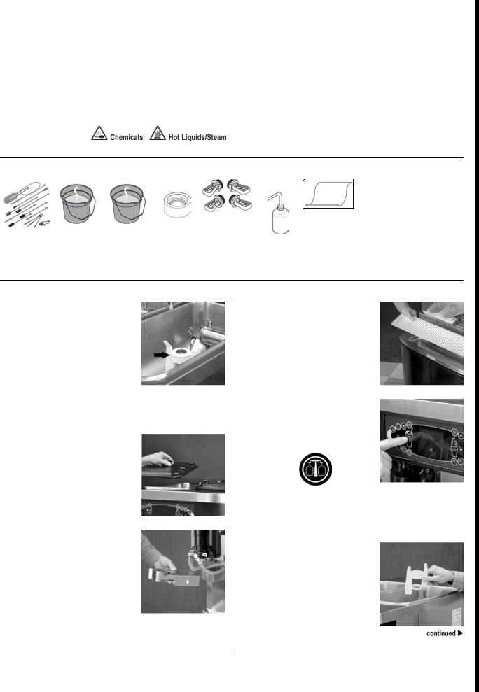
Tools and supplies
|
Brushes |
Bucket with Kay 5 |
Kay 5 |
Taylor Seal |
Taylor Lube HP |
Clean Sanitized |
|
Sanitizing Solution |
Sanitizing |
Install / |
Towels |
||
|
Solution |
Removal Tool |
Procedure – Set Up
1Fill heated topping wells with clean water.
Remove the topping containers. Fill the heated wells with clean water, up to the fill line located on the bottom of the well.
2Place topping heaters in ON position.
Place the topping heaters in the ON position by touching the topping heater symbols.
Note: Clean and sanitize topping containers, topping pumps, and heated wells weekly. (See PM cards SS01 W2 & W3.)
3Fill topping containers.
Fill the topping containers. Place the caramel and fudge topping containers in the heated wells and the remaining two containers in the unheated wells. Cover the containers.
4Sanitize topping ladles.
Sanitize the topping ladles and place them in the cold topping containers.
5Fill cup dispensers, cup lid holder and cone dispenser.
|
©McDonald’s Corporation · Planned Maintenance Manual · Revised January, 2021 |
Page 1 of 4 |
<![if ! IE]>
<![endif]>C602m rvesl mod-softchineand milkshake Company Taylor
<![if ! IE]>
<![endif]>3 SS Daily
<![if ! IE]>
<![endif]>D1
Opening Procedures (continued)
Procedure – Shake Side
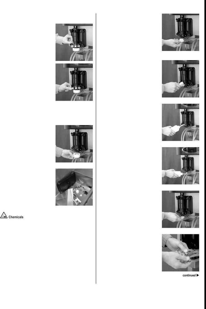
1Remove syrup valve retainers and syrup hole plugs.
Remove the syrup valve retainers and the syrup hole plugs.
Remove the o-rings from the syrup hole plugs.
2Remove draw valve cap.
Remove the draw valve cap and remove the o-ring.
3Sanitize parts.
Prepare a small amount of KAY-5 Sanitizer solution. Sanitize the o-rings, restrictor cap, syrup hole plugs, syrup valve retainers, draw valve cap, shake cup holder, front drip tray, and splash shield in this solution.
Sanitizer Solution
4Sanitize door spout, driven spinner, spinner blade, and syrup line fittings.
Brush clean each item for a total of 60 seconds, repeatedly dipping the brush in sanitizing solution.
5Sanitize syrup port holes.
Place a pail below the door spout.
Brush each syrup port hole 10 to 15 times. Dip the brush in sanitizing solution before brushing each port.
6Flush syrup port holes with sanitizing solution.
Insert tube end of squeeze bottle into each syrup port and squeeze the bottle firmly. Flush each port for 10 seconds.
7Flush door spout with sanitizing solution.
Flush the bottom of the door spout door with sanitizing solution.
8Install syrup valve retainers and restrictor cap on door spout.
9Remove syrup nose fittings.
Remove the syrup nose fitting from each syrup line by turning the syrup nose fitting counter-clockwise.
|
©McDonald’s Corporation · Planned Maintenance Manual · Revised January, 2021 |
Page 2 of 4 |
<![if ! IE]>
<![endif]>m rvesC l mod-softchineand milkshake Company Taylor
<![if ! IE]>
<![endif]>602
<![if ! IE]>
<![endif]>Daily
<![if ! IE]>
<![endif]>D1 3 SS
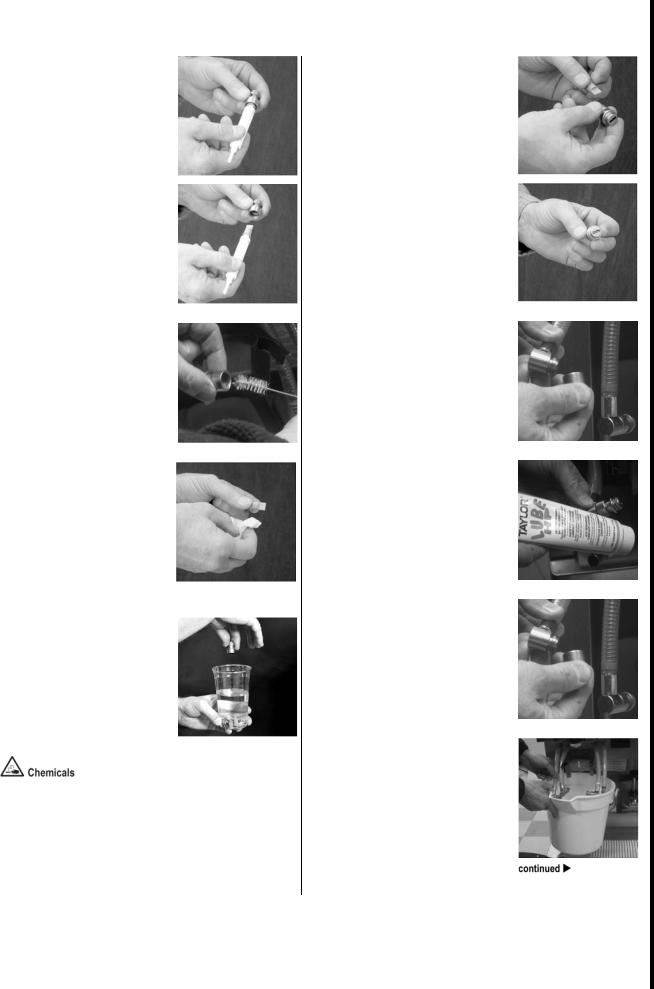
Opening Procedures (continued)
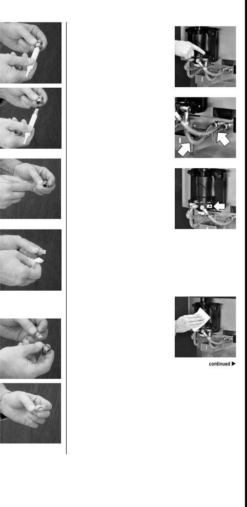
10Remove duckbill valve.
Remove the duckbill valve and the o-ring from each syrup nose fitting, by using the seal removal tool.
11Clean syrup nose fitting.
Using a brush and the sanitizing solution, brush clean the inside of each syrup nose fitting until there is no remaining syrup or mix inside the fitting.
12Sanitize syrup nose fittings and duckbill valve.
Using a clean, sanitized towel, gently wipe any syrup and mix from each duckbill valve.
Use a milkshake cup filled with sanitizing solution to thoroughly rinse the nose fittings and duckbill valve.
13Install duckbill valve into syrup nose fitting and install syrup nose fitting onto syrup line fitting.
Install the duckbill valve into the syrup nose fitting with the flat end aligned with the open slot in the fitting.
Install the syrup nose fitting onto the syrup line fitting. Tighten by hand (clockwise) until snug.
Install and lubricate the o-ring on the syrup nose fitting.
14Install syrup valves.
Raise the syrup valve retainer and install the syrup valve. Push the retainer down to hold the valve in place. Repeat for each syrup valve.
15Check syrup lines for air pockets in the line.
If air pockets are present, prime the syrup lines. (See Operator Manual for priming syrup lines.)
16Install syrup plugs for unused syrup lines.
Install a syrup hole plug into the syrup port in the door whenever a syrup line is not in use. (Example: When the optional flavor shake is not being served.)
Do not install an empty syrup line into the syrup port of an unused syrup line.
Note: The syrup system must be flushed and sanitized weekly.
(See PM card SS01 W1)
17Wipe exterior of machine.
Using a clean, sanitized towel, wipe down the freezer door, front panel, and other areas that have a build up of moisture or food substance.
|
©McDonald’s Corporation · Planned Maintenance Manual · Revised January, 2021 |
Page 3 of 4 |
<![if ! IE]>
<![endif]>m rvesC l mod-softchineand milkshake Company Taylor
<![if ! IE]>
<![endif]>602
<![if ! IE]>
<![endif]>Daily
<![if ! IE]>
<![endif]>D1 3 SS
Opening Procedures (continued)
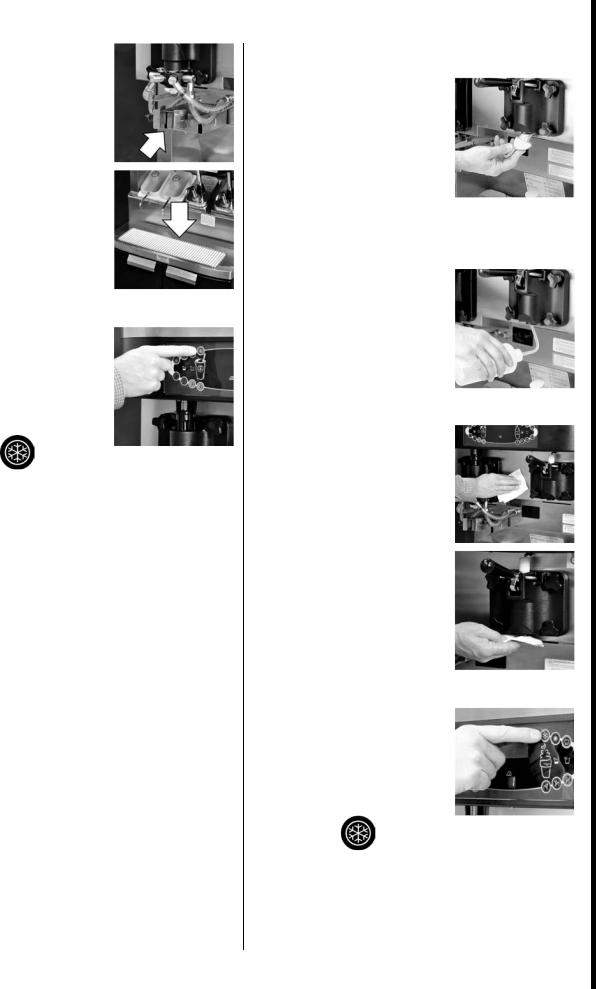
18Install shake cup holder, front drip tray and splash shield.
19Select the AUTO symbol.
When ready to resume normal operation, touch the AUTO symbol. The frozen product should be ready to serve in approximately 10 minutes.
Note: This step should be performed approximately 15 minutes prior to serving product.
Procedure – Soft Serve Side
1Sanitize door spout and bottom of draw valve.
With a pail placed beneath the soft serve door, dip the door spout brush in sanitizing solution. Brush clean the door spout and bottom of the draw valve. Repeatedly dip the brush in sanitizing solution and brush clean each item for 60 seconds.
2Flush door spout and bottom of draw valve with sanitizing solution.
Use the squeeze bottle filled with sanitizing solution to flush the door spout and bottom of the draw valve.
3Wipe exterior of machine.
Using a clean, sanitized towel, wipe down the freezer door, front panel, and other areas that have a build up of moisture or food substance.
4Select the AUTO symbol.
When ready to resume normal operation, touch the AUTO symbol. The frozen product should be ready to serve in approximately 10 minutes.
Note: This step should be performed approximately 15 minutes prior to serving product.
|
©McDonald’s Corporation · Planned Maintenance Manual · Revised January, 2021 |
Page 4 of 4 |
<![if ! IE]>
<![endif]>m rvesC l mod-softchineand milkshake Company Taylor
<![if ! IE]>
<![endif]>602
<![if ! IE]>
<![endif]>Daily
<![if ! IE]>
<![endif]>D1 3 SS
|
Closing Procedures |
Daily |
SS 3 D2 |
|||||||||
|
Why |
Prepare Milkshake/Soft-Serve machine for the heat treatment cycle |
||||||||||
|
Time required |
30 minutes |
||||||||||
|
Time of day |
At closing |
24-hour restaurants: one hour before heat treatment cycle |
begins
Hazard icons
Tools and supplies
|
Brushes |
SolidSense All |
Kay 5 Sanitizing |
Valve Cap |
Syrup Hole Plugs |
Kay 5 Sanitizing |
Clean Sanitized |
|
Purpose Super |
Solution |
Solution |
Towels |
|||
|
Concentrate (APSC) |
||||||
|
Solution |
Procedure – Shake Side
1Fill mix hopper.
Fill the hopper with fresh mix, up to the line on the agitator paddle. Do not fill above the agitator paddle.
Important: The level of mix in the hopper must be at the line on the agitator paddle. The mix low light must not be on.
2Remove hopper cover.
3Remove milkshake cup holder.
4Remove drip tray and splash shield.
5Remove agitator paddle.
Select the calibrate symbol to momentarily stop the agitator paddle from turning.
Important: Make sure your hands are clean and sanitized before performing the next steps.
With sanitized hands, remove the agitator paddle from the hopper.
|
©McDonald’s Corporation · Planned Maintenance Manual · Revised January, 2021 |
Page 1 of 5 |
<![if ! IE]>
<![endif]>C602m rvesl mod-softchineand milkshake Company Taylor
<![if ! IE]>
<![endif]>Daily
<![if ! IE]>
<![endif]>3 SS
<![if ! IE]>
<![endif]>D2

Closing Procedures (continued)
6Remove restrictor cap.
Remove the restrictor cap from the door spout.
7Clean and sanitize parts.
At the sink, brush clean and sanitize:
Agitator paddle
Hopper cover
Milkshake cup holder
Milkshake restrictor cap
Drip tray
Splash shield
Syrup hole plugs
Spout cap
Spout cap o-ring
Place the restrictor cap, splash shield, drip tray, and milkshake cup holder on a clean, dry surface to air dry overnight or until the heat treatment cycle is complete.
APSC & Sanitizer solution
8Install agitator paddle.
Select the calibrate symbol to momentarily stop the agitator drive motor.
Using sanitized hands, reinstall the agitator paddle on the drive post in the hopper.
9Install hopper cover.
10Remove syrup lines.
Raise the retaining pins and remove the syrup valves.
11Clean syrup port holes.
Place a bucket beneath the door. Brush clean each syrup port hole 10 to 15 times. Dip the brush in cleaning solution before brushing each port.
Brush each item for a total of 60 seconds.
APSC solution
12Clean door spout, bottom of driven spinner, spinner blade and syrup line fittings.
Brush clean each item for a total of 60 seconds, repeatedly dipping the brush in cleaning solution.
13Clean syrup valve retainers and holes.
With sanitized hands, remove the syrup valve retainers. Dip the brush in cleaning solution and brush clean the retainers and the retainer holes. Reinstall the syrup valve retainers.
|
©McDonald’s Corporation · Planned Maintenance Manual · Revised January, 2021 |
Page 2 of 5 |
<![if ! IE]>
<![endif]>C602m rvesl mod-softchineand milkshake Company Taylor
<![if ! IE]>
<![endif]>3 SS Daily
<![if ! IE]>
<![endif]>D2
Closing Procedures (continued)
14Flush syrup port holes with sanitizing solution.
Insert the tube end of the squeeze bottle filled with sanitizing solution into each syrup port. Squeeze the bottle firmly. Flush each port for 10 seconds.
APSC solution
15Flush door spout with sanitizing solution.
Flush the bottom of the door spout door with sanitizing solution.
16Fill valve cap with sanitizing solution and install.
Fill the insulated valve cap with sanitizing solution and install the cap onto the milkshake door spout.
17Install syrup hole plugs.
Raise the retainer pins. Install a syrup hole plug into each syrup port. Lower the retainer pins to secure the syrup hole plugs.
18Sanitize syrup nose fittings.
Hold the squeeze bottle over a bucket. Squeeze the bottle and thoroughly rinse the slot of each syrup nose fitting.
Wipe the outside of the syrup nose fittings with a clean, sanitized towel.
Note: The syrup system must be flushed and sanitized weekly.
(See PM card SS01 W1.)
Procedure – Soft Serve Side
1Fill mix hopper.
Fill the hopper with fresh mix, up to the line on the agitator paddle. Do not fill the mix hopper above the agitator paddle.
Important: The level of mix in the hopper must be at the line on the agitator paddle. The mix low light must not be on.
2Place topping heaters in OFF position.
Turn the topping heaters OFF by selecting the topping heater symbols.
3Remove, clean, and sanitize hopper cover.
APSC & Sanitizer solution
4Remove, clean, sanitize, and reinstall agitator paddle.
Select the calibrate symbol to momentarily stop the agitator paddle from turning.
Important: Make sure your hands are clean and sanitized before performing the next steps.
|
©McDonald’s Corporation · Planned Maintenance Manual · Revised January, 2021 |
Page 3 of 5 |
<![if ! IE]>
<![endif]>C602m rvesl mod-softchineand milkshake Company Taylor
<![if ! IE]>
<![endif]>3 SS Daily
<![if ! IE]>
<![endif]>D2
Closing Procedures (continued)
Remove the agitator paddle from the hopper and take it to the sink. Brush clean, sanitize, and reinstall the agitator paddle.
5 Install hopper cover.
6Clean door spout and bottom of draw valve.
Place a bucket beneath the soft-serve door. Dip the door spout brush into cleaning solution and brush clean the door spout and bottom of the draw valve. Repeatedly dip the brush in cleaning solution and brush clean each item for 60 seconds.
APSC solution
7Flush door spout with sanitizing solution.
Use the squeeze bottle filled with sanitizing solution to rinse the bottom of the door spout. Rinse the spout with sanitizing solution for 10 seconds.
Sanitizer solution
8Remove, clean and reinstall drip pans.
Remove the drip pans and take them to the sink. Brush clean, sanitize, and reinstall the drip pans.
Note: Mix in the drip pans indicates there is a leak that needs to be corrected before damage occurs inside the machine.
Examples:
If mix is in the front or side drip pans, inspect/replace the beater drive shaft seals. If mix is in the rear drip pan, inspect/replace the pump drive shaft seals.
9Wipe exterior of machine.
Use a clean, sanitized towel to wipe down the freezer doors, front panels, and any other areas that have a build-up of either moisture or food substance.
|
©McDonald’s Corporation · Planned Maintenance Manual · Revised January, 2021 |
Page 4 of 5 |
<![if ! IE]>
<![endif]>C602m rvesl mod-softchineand milkshake Company Taylor
<![if ! IE]>
<![endif]>3 SS Daily
<![if ! IE]>
<![endif]>D2
Closing Procedures (continued)
10 Make sure unit is in AUTO.
Note: The machine must be in AUTO (or STANDBY) to start the heat treatment cycle at the programmed time.
DO NOT attempt to draw product or disassemble the machine during the HEAT cycle. The product is hot and under extreme pressure.
When the heat cycle is complete, the control panel will change to the STANDBY mode. The STANDBY symbols will be illuminated.
<![if ! IE]>
<![endif]>C602m rvesl mod-softchineand milkshake Company Taylor
<![if ! IE]>
<![endif]>3 SS Daily
<![if ! IE]>
<![endif]>D2
|
©McDonald’s Corporation · Planned Maintenance Manual · Revised January, 2021 |
Page 5 of 5 |
![]()
|
Clean and sanitize syrup lines with duckbill |
Weekly |
SS 3 W1 |
|||||||||
|
valves |
|||||||||||
|
Why |
To break the bacteria cycle |
||||||||||
|
Time required |
5 minutes to prepare |
20 minutes to complete |
|||||||||
|
Time of day |
At close |
For 24-hour restaurants: during breakfast menu |
|||||||||
|
Hazard icons |
Tools and supplies
|
Brushes |
Bucket, SolidSense |
Bucket, clean and |
Bucket, soiled towels |
Bucket, plastic |
Cold-drink cup |
Kay-5 Sanitizing |
|
All Purpose Super |
sanitizer-soaked |
solution |
||||
|
Concentrate (APSC) |
towels |
|
Plastic wrap |
Taylor Lube HT |
Kay-5 Sanitizing |
|
solution |
Procedure
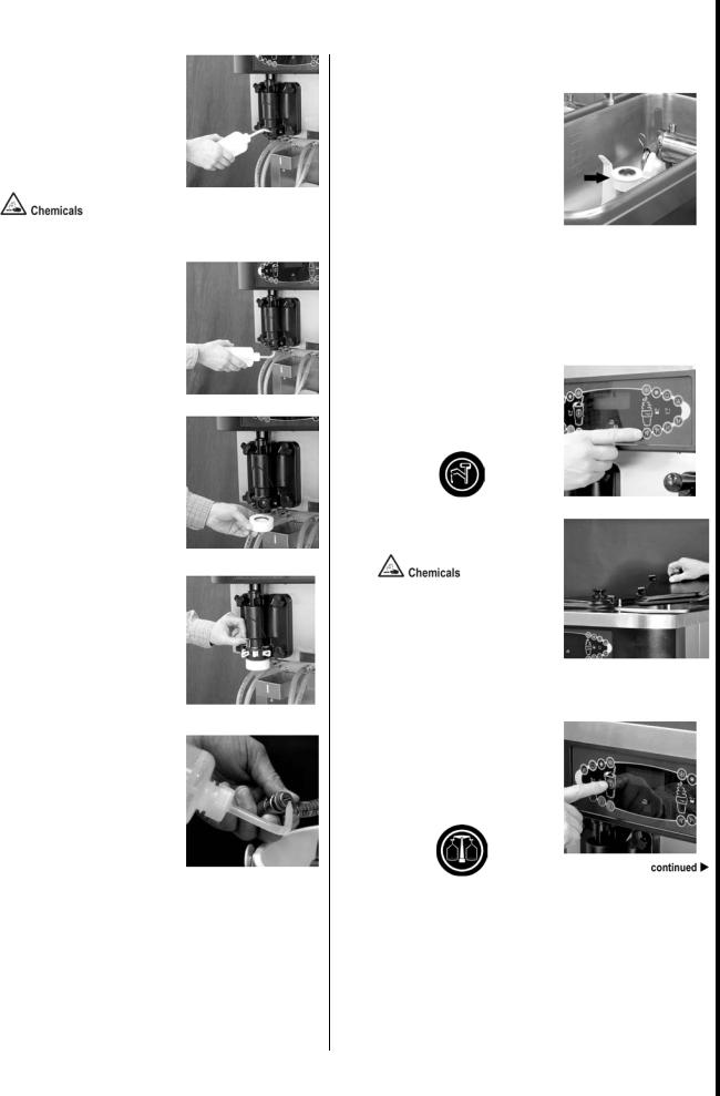
1Disconnect the QD fitting
Disconnect the QD fitting on the syrup bag.
Remove the syrup bags with the line attached from the cabinet.
Wipe the outside of the feed tubes or the hose connector fittings with a clean, sanitizer-soaked towel.
Sanitizer solution
2Place the syrup bag on a level surface. Remove the syrup bag line from the syrup bag.
4Re-connect the QD
Fitting/Hose from the syrup bag
Place the syrup feed hose in a bucket of APSC solution.
APSC Solution
5Clean inside of cabinet.
Wipe down the inside of the syrup cabinet with a clean, sanitizer-soaked towel. Spray resistant areas with additional sanitizer solution.
3Cover the syrup inlet port with plastic wrap.
|
©McDonald’s Corporation · Planned Maintenance Manual · Revised January, 2021 |
Page 1 of 4 |
<![if ! IE]>
<![endif]>C602 model machine serve-soft and milkshake Company Taylor
<![if ! IE]>
<![endif]>Weekly
<![if ! IE]>
<![endif]>W1 3 SS
Clean and sanitize syrup lines with duckbill valves (continued)
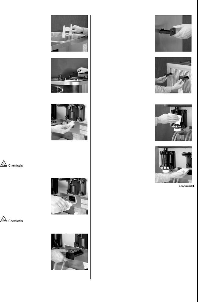
6Place empty bucket under milkshake draw valve.
Place a clean plastic bucket under the milkshake draw valve.
7Remove syrup line from milkshake freezer door.
Disconnect the corresponding syrup line from the milkshake freezer door by raising the syrup valve retainer. Pull the valve straight out.
8Place syrup line and valve in bucket.
Hang the syrup line and valve in the empty bucket.
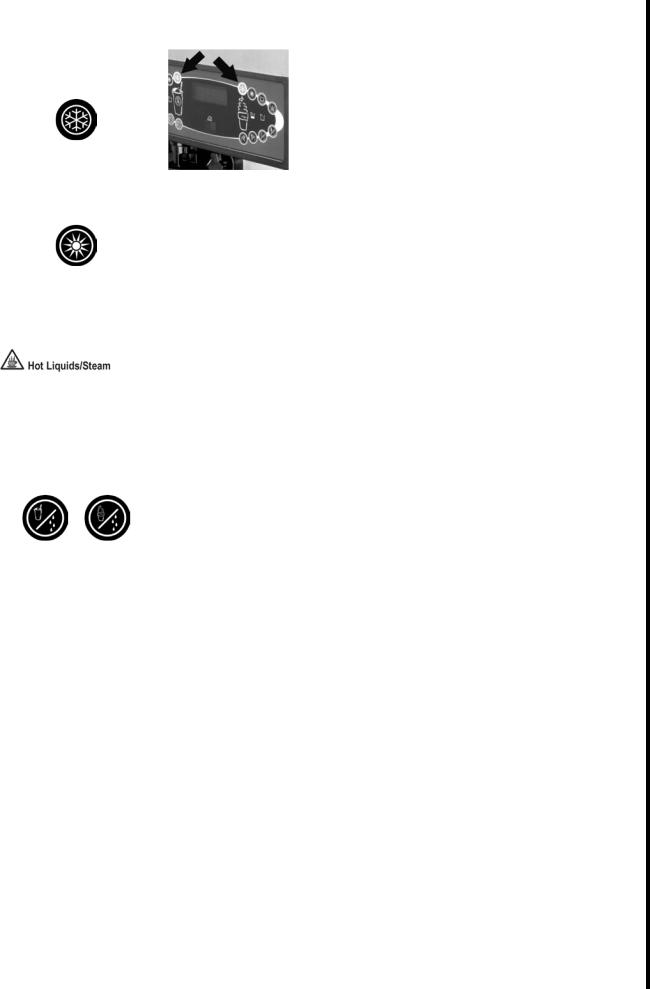
9Start flow of APSC solution.
Press the Calibration key on the control panel to display the menu options.
Touch the Auto key to move the arrow to “Syrup Prime.”
Touch the Calibration key again to display the syrup prime screen.
Press the Flavor Select key for the correct flavor, to start the flow of APSC through the line.
APSC solution
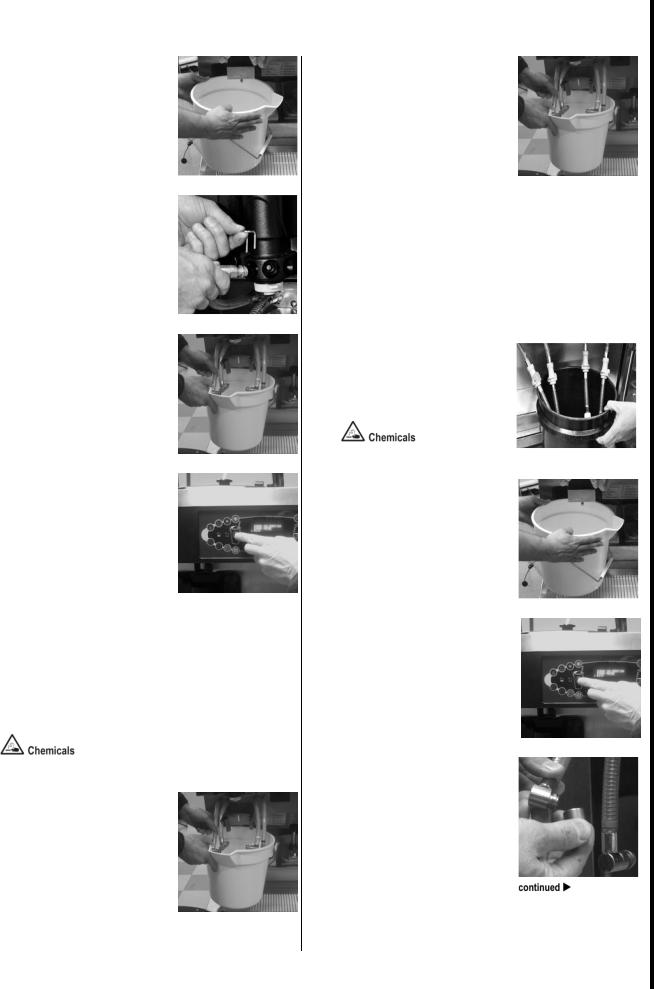
10Flush syrup line with APSC solution.
Allow the APSC solution to continue to flow into the empty bucket until all the syrup is flushed from the line. When the liquid from the syrup line runs clear, the line is completely flushed.
11Pump all liquid from syrup line.
Remove the syrup feed tube from the bucket of APSC solution and continue to run the pump until APSC solution no longer runs from the syrup line.
Touch the Flavor Select key to stop the flow of APSC solution through the syrup line.
12Rinse with clean, hot water
Repeat steps 7-10 with clean, hot water.
13Place feed tubes in sanitizer solution.
Place the syrup bag connect fittings into a bucket of sanitizer solution.
Sanitizer solution
14Place empty bucket under milkshake draw valve.
Place a clean plastic bucket under the milkshake draw valve.
15Flush syrup line with sanitizer solution.
Repeat steps 7 through 9 using sanitizer solution.
16Remove nose fitting.
Unscrew the nose fitting from the syrup valve in the bucket by turning the cap counterclockwise.
|
©McDonald’s Corporation · Planned Maintenance Manual · Revised January, 2021 |
Page 2 of 4 |
<![if ! IE]>
<![endif]>C602 model machine serve-soft and milkshake Company Taylor
<![if ! IE]>
<![endif]>Weekly
<![if ! IE]>
<![endif]>W1 3 SS
Clean and sanitize syrup lines with duckbill valves (continued)
17Remove valve and o-ring.
Remove the duckbill valve and o-ring from each syrup nose fitting, by using the seal removal tool.
18Clean nose and elbow fitting.
Use the white end of the double-ended brush to scrub the inside of the syrup nose fitting and the elbow fitting. Remove any residual particles.
19Clean duckbill valves.
Use a clean, sanitizer-soaked towel to wipe any syrup from the duckbill valves.
20Sanitize syrup valve fittings.
Fill a cup with sanitizer solution. Submerge the syrup valve fittings in the sanitizer solution in the cup. Rotate the cup gently so the fittings are washed thoroughly. Allow to soak for at least one minute.
Sanitizer solution
21Insert duckbill valve.
Install the duckbill valve into one of the nose fittings with the flat end aligned with the open slot in the nose fitting.
Do not lubricate the duckbill valve.
22Connect nose fitting.
Screw the nose fitting onto one of the syrup valve elbows by turning it clockwise. Tighten it by hand until snug.
23Install and lubricate o-ring.
Push one of the o-rings onto the nose fitting and lubricate it with Taylor Lube HP.
24Reassemble remaining valves.
Repeat steps 20 through 22 to reassemble the remaining syrup valves.
25Place clean bucket under milkshake draw valve.
Place a clean plastic bucket under the milkshake draw valve. Position the sanitized valves so they are hanging over the bucket.
|
©McDonald’s Corporation · Planned Maintenance Manual · Revised January, 2021 |
Page 3 of 4 |
<![if ! IE]>
<![endif]>C602 model machine serve-soft and milkshake Company Taylor
<![if ! IE]>
<![endif]>Weekly
<![if ! IE]>
<![endif]>W1 3 SS
 Loading…
-
Page 1
Soft serve/shake combination freezer taylor model c602 place this chapter in the shakes/desserts section of the equipment manual. Manufactured exclusively for mcdonald’s® by taylor® company 750 n. Blackhawk blvd. Rockton, il 61072 phone: (815) 624-8333 toll free number outside illinois: 1 (800) 228-…
-
Page 2
1 introduction the model c602 is a combination shake and soft serve freezer. The soft serve side uses a 3.4 quart (3.2 liter) freezing cylinder with a single spout door. The shake side has a 7 quart (6.6 liter) freezing cylinder with a four flavor dispensing door. The touch panel has four flavor sym…
-
Page 3
2 do not operate the freezer unless all service panels and access doors are restrained with screws. Failure to follow this instruction may result in severe personal injury from hazardous moving parts. Do not attempt to draw product or disassemble the unit during the heat cycle. The product is hot an…
-
Page 4
3 notes :.
-
Page 5
4 parts identification/functions exploded view (see figure 1) item part no. Description qty. Function warr. Class 1 053809-1 cover-hopper*black* 2 protects mix in mix hopper from any debris. Helps keep temperature in mix hopper uniform. 103 2 x44797 agitator assembly 2 stirs product in mix hopper to…
-
Page 6
5 exploded view (continued) item part no. Description qty. Function warr. Class 20 056131 plate-dec. 1 touch sensor display panel on front of machine. 103 21 055957 panel-side left 1 panel which provides access to internal components. 103 22 052779-3 filter-air 18.0 l x 13.5 h x .70 w 2 filters dust…
-
Page 7
6 front view (see figure 2) item part no. Description qty. Function warr. Class 1 x35584ser2 motor a.-spinner 1 turns spinner shaft assembly. 103 2 059462 solenoid -draw valve 1 energized to raise the shake draw valve. 103 3 020108 coupling-flexible w/screws 1 connects spinner motor to coupling asse…
-
Page 8
7 front view (continued) item part no. Description qty. Function warr. Class 15 x53800-brn pump a.-syrup- heated (chocolate) 1 dispenses heated sundae topping. 103 16 x53800-tan pump a.-syrup- heated (caramel) 1 dispenses heated sundae topping. 103 17 056008 holder-cup shake 1 holds cup in place dur…
-
Page 9
8 front view figure 2.
-
Page 10
9 syrup cabinet view (see figure 3) item part no. Description qty. Function warr. Class 1 056016 shelf-syrup 1 provides access to syrup pumps. 103 2 052916 pump-peristaltic 4 pumps syrup to freezer door. 103 3 058725 motor-gear 161 rpm 4 drives peristaltic pump rollers. 103 4 059144 rack-syrup cabin…
-
Page 11
10 mix pump & tubes (see figure 4) item part no. Description qty. Function warr. Class 1 052916 pump-peristaltic 4 contains rollers to propel syrup. 103 2 x54978 kit a.-peristaltic pump tube 4 compressed by pump rollers to propel syrup. 000 3 053036 ferrule-.625 id 2 ea. Clamps syrup hose on fitting…
-
Page 12
11 mix hopper — top view (see figure 5) item part no. Description qty. Function warr. Class 1 x44761 sleeve a.-mix pump 2 hub used to hold the air/mix pump in a locked position. 103 2 x41348 probe a.-mix out 2 electrical device to indicate level of mix in the hopper. Activates the mix out light on f…
-
Page 13
12 x57028-xx pump a. — mix simplified — shake (see figure 6) item part no. Description qty. Function warr. Class 1 — 7 x57028-xx pump a.-mix simplified shake 1 delivers air and mix to the freezing cylinder. 103 1 057944 cylinder-pump- hopper-shake 1 chamber to house the piston. 103 2 x55450 pin a.-r…
-
Page 14
13 x57028-xx pump a. — mix simplified — shake figure 6.
-
Page 15
14 x57029-xx pump a. — mix simplified — soft serve (see figure 7) item part no. Description qty. Function warr. Class 1 — 7 x57029-xx pump a.-mix simplified soft serve 1 delivers air and mix to freezing cylinder. 103 1 057943 cylinder-pump- hopper-soft serve 1 chamber to house the piston. 103 2 x554…
-
Page 16
15 x57029-xx pump a. — mix simplified — soft serve figure 7.
-
Page 17
16 x56652 syrup line assembly — triple thick shake syrup (see figure
 item part no. Description qty. Function warr. Class 1 053036 ferrule-.625 id 2 clamps syrup hose on fitting. 000 2 056675 fitting-barb 1 connects syrup lines to front panel. 103 3 500205 o-ring 1 provides seal for quick disconne…
 -
Page 18
17 x59304 syrup line assembly — thin viscosity syrup (see figure 9) item part no. Description qty. Function warr. Class 1 029834 ferrule-.650 id 2 clamps syrup hose on fitting. 000 2 056675 fitting-barb 1 connects syrup lines to front panel. 103 3 500205 o-ring 1 provides seal for quick disconnect f…
-
Page 19
18 x58450 syrup line assembly — syrup-in-bag option (see figure 10) item part no. Description qty. Function warr. Class 1 024278 o-ring-1/2 od x .070 1 provides a seal in the pump tube connection. 000 2 054526 fitting-male 1 connects to the pump tube. 103 3 053036 ferrule-.625 id np brass 2 secures …
-
Page 20
19 accessories (see figure 11) item part no. Description qty. Function warr. Class 1 x56121 dispenser a.-cone 1 dispenses shake and soft serve cups and cones. 103 1a 052193 baffle-rubber cone 2 holds and dispenses soft serve cones. 000 2 x58474 kit a.-syrup plug kit 4 seals syrup ports in the shake …
-
Page 21
20 accessories item part no. Description qty. Function warr. Class * x49463-59 kit a.-tune up c602 1 tune up kit containing: 1/x56200-10 pump kit, 1/x56200-12 draw valve kit, 1/x56200-13 shake door kit, 1/x56200-14 soft serve door kit, 1/x56200-15 syrup valve kit, 1/048260 o-ring removal tool. 000 *…
-
Page 22
21 x44127 brush kit assembly (see figure 12) item part no. Description qty. Function warr. Class 1 013071 black bristle brush 1 used to clean rear shell bearing and mix pump drive hub. 000 2 013072 double end brush 1 used to clean o-rings, holes in metal parts, piston grooves, mix inlet tube, mix in…
-
Page 23
22 beater door assembly — shake side (see figure 13) item part no. Description qty. Function warr. Class 1 032560 seal-drive shaft 1 provides seal from product inside freezing cylinder to internal areas of freezer. 000 2 050985 shaft-beater 7 qt. Fluted blade 1 connects beater assembly to gear unit….
-
Page 24
23 beater door assembly — shake side figure 13.
-
Page 25
24 beater door assembly — soft serve side (see figure 14) item part no. Description qty. Function warr. Class 1 x56421-1 handle a.-draw 1 operational component of the draw valve assembly. 103 2 055989 nut-stud 4 tightening mechanism to secure freezer door to freezing cylinder. 103 3 x57332-ser door …
-
Page 26
25 beater door assembly — soft serve side figure 14.
-
Page 27
26 x53800-brn/tan syrup pump (see figure 15) item part no. Description qty. Function warr. Class 1 x36576-tan x36576-brn plunger a. 1 used to dispense toppings. Nnn 1a 032762-tan 032762-brn knob-plunger 1 holds plunger assembly in place. Tan and brn indicate the hot caramel and hot fudge toppings. 1…
-
Page 28
27 x53800-brn/tan syrup pump figure 15.
-
Page 29
28 059088 tray-parts-shake side figure 16 item part no. Description 1 x50958 beater a.-7 qt. 2 041103 blade-scraper-16” 3 050985 shaft-beater 7 qt. 4 032560 seal-drive shaft 5 055989 nut-stud 6 053890 o-ring -syrup port 11mm id green 7 053867 plug-syrup port 8 034054 spinner 9 x59331 blade a.-spinne…
-
Page 30
29 059087 tray-parts-soft serve side figure 17 item part no. Description 1 x56421-1 handle a.-draw 2 055819 pin-pivot 3 050348 bearing-front 4 055989 nut-stud 5 014402 o-ring (draw valve) 6 048926 gasket (freezer door) 7 x55820 valve a.-draw 8 x57332-ser door a.-w/baffle item part no. Description 9 …
-
Page 31
30 056525 tray-parts-pump-simplified figure 18 shake side item part no. Description 1 044641 clip-mix pump retainer 2 057944 cylinder-pump- hopper-shake 3 x55450 pin a.-retaining 4 053526 piston 5 044731 pin-cotter 6 020051 o-ring 2-1/8” od- red 7 056873-xx cap-valve 8 053527 gasket-simplified pump …
-
Page 32
31 important to the operator figure 19 item description function 1 keypad-shake used for selecting operating functions on the shake side of the machine. 2 display-vacuum fluorescent menu (vfd) screen which displays menu options and notifies operator if a fault is detected. 3 keypad-menu (entry/exit)…
-
Page 33
32 symbol definitions to better communicate in the international arena, the words on many of our operator keys have been replaced by symbols to indicate their functions. Your taylor equipment is designed with these international symbols. The following chart identifies the symbol definitions. = auto …
-
Page 34
33 heat mode symbol when the heat mode symbol is illuminated, the freezer is in the process of a heat cycle. The heat mode symbol may be selected to start a heat cycle following a freezer soft lock condition. For some international models, the heat symbol can be selected to manually start a heat cyc…
-
Page 35
34 shake fill level adjustment the portion control sensor located under the cup holder can be adjusted to fill the cup to the desired level. If the fill level is too low, or the cup is overfilling, it may be necessary to adjust the sensor position. (see figure 22.) figure 22 1. Using a crescent wren…
-
Page 36
35 4. Fill the topping containers with topping. Place the caramel and fudge topping containers in the heated wells. Place the remaining two topping containers in the unheated wells. Cover the containers. 5. Sanitize the two topping ladles and place in the cold topping containers. 6. Fill the cup dis…
-
Page 37
36 5. Fill the squeeze bottle with sanitizing solution. With a pail beneath the door, insert the tube end of the squeeze bottle into the syrup port, and squeeze the bottle firmly. This action will force solution out of the adjacent port and down around the spinner. This procedure should be performed…
-
Page 38
37 14. Install the duckbill valve into the syrup nose fitting with the flat end aligned with the open slot in the syrup nose fitting. Note: replace the duckbill valve if it is damaged or extends past the syrup nose fitting slot. (see figure 29.) figure 29 15. Install the syrup nose fitting onto the …
-
Page 39
38 21. Touch the auto symbol or the optional flavor symbol to scroll the arrow to syrup prime. (see figure 33.) unflavored draw syrup calibration > syrup prime exit figure 33 22. Touch the calibration symbol to enter the syrup prime mode. (see figure 34.) syrup prime select a flavor press to clear f…
-
Page 40
39 30. When ready to resume normal operation, touch the auto symbol . (see figure 37.) the control has a feature in the manager’s menu to enable or disable the auto start feature. When auto start in enabled, the machine will automatically exit the standby mode and start both sides in the auto mode a…
-
Page 41
40 once this rate is set, the correct amount of syrup will be blended with the shake base regardless of the size of shake served. Please note that syrup calibration is critical when changing the promotional 4th flavor syrup. Calibration procedure syrup lines must be properly primed with syrup to eli…
-
Page 42
41 5. To calibrate the syrup dispensing rate, hold the small portion of the calibration cup under the valve for the flavor to be calibrated. Touch the corresponding flavor select symbol to activate the syrup pump and start the flow of syrup. When the syrup level measures one ounce, touch the same fl…
-
Page 43
42 8. Touch the auto symbol or the optional flavor symbol to scroll the arrow to syrup prime. (see figure 47.) unflavored draw syrup calibration > syrup prime exit figure 47 9. Touch the calibration symbol to enter the syrup prime mode. (see figure 48.) syrup prime select a flavor press to clear fig…
-
Page 44
43 5. Place the restrictor cap, front drip tray, shake cup holder and splash shield on a clean, dry surface to air-dry overnight or until the heating cycle is complete. 6. Prepare a small amount of mcd sanitizer (hcs) solution. Use one packet in 2.5 gallons (9.5 liters) of water (100 ppm). 7. Saniti…
-
Page 45
44 13. Fill the squeeze bottle with cleaning solution. With a pail beneath the door, insert the tube end of the squeeze bottle into the syrup ports, and squeeze the bottle firmly. This action will force solution out of the adjacent port and down around the spinner. This procedure should be performed…
-
Page 46
45 soft serve side this procedure must be done at the close of business. Important: the level of mix in the mix hopper must be above the mix low probe. (the mix low light must not be on.) note: if the brush clean counter display has counted down to one day, do not add mix. The machine must be disass…
-
Page 47
46 10. Remove, clean and reinstall the long drip pan through the front panel. (see figure 60.) figure 60 11. Remove, clean and reinstall the two short drip pans in the rear panel. 12. Remove, clean and reinstall the two notched drip pans in the left and right side panels. (see figure 61.) figure 61 …
-
Page 48
47 scheduled maintenance — syrup system syrup pump tube removal 1. Remove the syrup feed tubes from the syrup containers. Wipe the outside of the feed tubes with a clean, sanitized towel. For syrup bag system: disconnect the syrup bag fitting from each bag. 2. Remove the syrup containers and the pum…
-
Page 49
48 pump tube installation 1. Lubricate the o-rings on the syrup line fittings with taylor lube hp. Figure 64 2. Press the fittings into the new pump tube. 3. Install the clips into their respective collars. 4. Using your hands, rotate the pump rollers so they are in the 10 and 2 o’clock position. 5….
-
Page 50
49 15. Install the duckbill valve into the syrup nose fitting, with the flat end aligned with the open slot in the syrup nose fitting. Note: replace the duckbill valve if it is damaged or extends past the syrup nose fitting slot. (see figure 29.) figure 65 16. Install the syrup nose fitting onto the…
-
Page 51
50 syrup topping pump syrup topping pump disassembly before the first use, and after use weekly, disassemble and clean the pump. 1. Flush and rinse the pump in a container of warm water. Place the lower end of the pump into the water container. Operate the pump until only warm water flows from the d…
-
Page 52
51 8. Remove the seal o-ring from the seal. (see figure 72.) figure 72 9. Remove the discharge tube lock nut by turning it counterclockwise. Remove the discharge lock nut from the discharge tube. (see figure 73.) figure 73 10. Remove the lid by sliding it off the discharge tube. 11. Remove the cylin…
-
Page 53
52 4. Insert the black shielded brush into the top side of the inlet valve. Scrub this area, specifically around the steel ball. (see figure 77.) figure 77 5. Insert the black shielded brush into the top side of the outlet valve. Scrub this area, specifically around the steel ball. (see figure 78.) …
-
Page 54
53 syrup topping pump assembly after pump disassembly and cleaning is complete, assemble the pump. 1. Lubricate and install the seal o-ring into the seal. (see figure 82.) figure 82 2. Install the seal assembly onto the piston end of the plunger assembly. 3. Install the washer and spring onto the pl…
-
Page 55
54 10. Lubricate and install the 1-5/16” o-ring into the valve body. (see figure 86.) figure 86 11. Install the discharge tube onto the smaller opening in the valve body by aligning the flats on the discharge tube with the locking grooves on the valve body. Push down the discharge tube until it is s…
-
Page 56
55 draining product from the freezing cylinder to drain the product from the freezing cylinders on both sides of the machine, the steps will be the same. Therefore, first drain the product from the shake side, then go back and duplicate these procedures for the soft serve side. 1. Place the heater t…
-
Page 57
56 rinsing 1. Pour two gallons (7.6 liters) of cool, clean water into the shake mix hopper. With the white hopper brush, scrub the mix hopper, mix level sensing probes and the outside of the agitator drive shaft housing. Using the double ended brush, brush clean the mix inlet hole. (see figure 91.) …
-
Page 58
57 8. Prepare 2.5 gallons (9.5 liters) of mcd sanitizer (hcs) solution. Use one packet in 2.5 gallons (9.5 liters) of water (100 ppm). Repeat steps 2 through 7 with the sanitizing solution. Repeat steps 1 through 8 for the soft serve side of the freezer. Disassembly — shake side note: failure to rem…
-
Page 59
58 10. Remove the pump drive shaft from the drive hub in the rear wall of the mix hopper. (see figure 95.) figure 95 remove the two small o-rings and one large o-ring from the pump drive shaft. Disassembly — soft serve side note: failure to remove the parts specified below for brush cleaning and lub…
-
Page 60
59 10. Remove the two short drip pans from the rear panel. Remove the two notched drip pans from the left and right side panels. Take them to the sink for cleaning. (see figure 98.) figure 98 note: if the drip pans are filled with an excessive amount of mix, it is an indication that the drive shaft …
-
Page 61
60 equipment set-up freezing cylinder assembly — shake side make sure the power switch is in the off position. Failure to follow this instruction may result in severe personal injury from hazardous moving parts. With the parts tray available for the shake side: 1. Before installing the shake beater …
-
Page 62
61 if the blades are in good condition, place each scraper blade over the holding pins on the beater assembly. (see figure 104.) figure 104 note: the holes in the scraper blade must fit over the pins to prevent damage. 4. Holding the blades on the beater assembly, insert the beater assembly in the f…
-
Page 63
62 7. Insert the spinner shaft seal into the bottom of the draw valve as far as it will go. The spinner shaft seal should fit into the seal groove located inside the draw valve cavity. (see figure 108.) 11245 figure 108 important: inspect to see that the spinner shaft seal is correctly installed in …
-
Page 64
63 11. Place the freezer door o-ring into the groove on the back of the freezer door. Lubricate the outside diameter of the front bearing. Slide the front bearing into the door hub. Note: if necessary, put two small spots of lubricant at the 10 o’clock and 2 o’clock positions on the upper portion of…
-
Page 65
64 15. Raise the locking collar of the spinner coupling and insert the spinner shaft into the cavity of the coupling until the locking collar can drop into the locked position. (see figure 116.) figure 116 16. Snap the restrictor cap over the end of the door spout and install the syrup valve retaine…
-
Page 66
65 note: to ensure the mix does not leak out of the back of the freezing cylinder, the middle section of the boot seal should be convex or extend out from the seal. If the middle section of the boot seal is concave or extending into the middle of the seal, turn the seal inside out. (see figure 119.)…
-
Page 67
66 5. Install the beater shoes. (see figure 123.) figure 123 6. Slide the beater assembly the rest of the way into the freezing cylinder. Make sure the beater assembly is in position over the drive shaft by turning the beater slightly until the beater is properly seated. When in position, the beater…
-
Page 68
67 10. Install the freezer door. Insert the baffle rod through the beater in the freezing cylinder. With the door seated on the freezer studs, install the handscrews. Tighten equally in a criss-cross pattern to insure the door is snug. (see figure 129.) figure 129 11. Install the draw handle. Slide …
-
Page 69
68 mix pump assembly 1. Inspect the rubber pump parts. O-rings and gasket must be in 100% good condition for the pump and entire machine to operate properly. The o-rings and gasket cannot properly serve their intended function if nicks, cuts, or holes in the material are present. Replace any defecti…
-
Page 70
69 7. Insert the valve cap into the hole in the mix inlet adapter. (see figure 139.) 15111 figure 139 8. Insert the mix inlet assembly into the pump cylinder. (see figure 140.) 15112 figure 140 the adapter must be positioned into the notch located at the end of the pump cylinder. 9. Secure the pump …
-
Page 71
70 13. Slide the large black o-ring and the two smaller black o-rings into the grooves on the drive shaft. Thoroughly lubricate the o-rings and shaft. Do not lubricate the hex end of the shaft. (see figure 145.) figure 145 14. Install the hex end of the drive shaft into the drive hub at the rear wal…
-
Page 72
71 6. Caution! Install the pump end of the mix feed tube and secure with the cotter pin. Failure to follow this instruction could result in sanitizer spraying on the operator. 7. Using the white hopper brush, clean the mix level sensing probes, the mix hopper, mix inlet hole, the outside of the agit…
-
Page 73
72 17. Remove the cotter pin from the pump. Stand the mix feed tube in the corner of the mix hopper. Place the cotter pin in position in the outlet fitting of the pump. Figure 152 18. Remove the restrictor cap and the syrup hole plugs. 19. Return to the freezer with a small amount of sanitizing solu…
-
Page 74
73 5. Prepare another 2.5 gallons (9.5 liters) of mcd sanitizer (hcs) solution. Use one packet in 2.5 gallons (9.5 liters) of water (100 ppm). 6. Pour the sanitizing solution into the mix hopper. 7. Brush the exposed sides of the hopper. Wait at least 5 minutes before proceeding with these instructi…
-
Page 75
74 priming — shake side note: use only fresh mix when priming the freezer. 1. With a mix pail beneath the door spout, touch any flavor select symbol to open the draw valve. Pour 2-1/2 gallons (9.5 liters) of fresh mix into the mix hopper and allow it to flow into the freezing cylinder. This will for…
-
Page 76
75 during the initializing… Language screen, the alarm will be on. If the system de- tects corrupt data during initializing, the following display will alert the operator that the control settings may have been changed (see figure 159.) service req’d nvram fault reset to defaults figure 159 once t…
-
Page 77
76 do not attempt to draw product or disassemble the unit during the heat cycle. The product is hot and under extreme pressure. In the heat cycle, the mix temperature in the hoppers and freezing cylinders must be raised to 151 _ f (66.1 _ c) within 90 minutes. When the heating phase is complete, the…
-
Page 78
77 if the machine has hard locked and an attempt is made to enter auto, the machine will enter the standby mode and display the following message. (see figure 170.) freezer locked figure 170 to restore the message that identified the rea- son for the hard lock, turn the power switch off for five sec…
-
Page 79
78 when one of these messages appears, automatic freezer operation cannot take place until the freezer is disassembled and brush cleaned, or has completed a heat treatment cycle. Select the heat symbol to start a heat cycle, or select the wash symbol to disassemble and brush clean the machine. Once …
-
Page 80
79 the sundae side will continue operation in the mode it was in when the menu was selected. However, the sundae side control keys will not be lit and are non-functional when the manager’s menu or calibration menu is displayed. The control keys for both sides are functional in the manager’s menu whe…
-
Page 81
80 the verify calibration option is used to verify the amount of syrup dispensed is within the proper specification. (see figure 180.) verify calibration select a flavor figure 180 remove the syrup valve from the dispensing door. With the line fully primed with syrup, position the syrup valve over t…
-
Page 82
81 change the time by touching the auto or optional flavor symbol with the cursor under the hour position. Move the cursor to the minutes by selecting the calibration symbol . Once the correct minutes are entered, select the calibration symbol to advance the cursor to the month. (see figure 185.) se…
-
Page 83
82 enable the auto start time by selecting the auto symbol to move the arrow up to enable. Select the calibration symbol to advance to the next screen. (see figure 190.) auto start time 00:00 change > exit figure 190 program the auto start time by selecting the auto symbol to move the arrow to chang…
-
Page 84
83 the mix level audible option when enabled will alert the operator with an audible tone when there is mix low or mix out condition. The following screen is displayed upon selecting this option. (see figure 195.) mix level audible > enable disable figure 195 disable the audible tone feature by sele…
-
Page 85
84 faults occurring entering a heat treatment cycle power switch off — the power switch is off. Auto or stby off — the control was not in auto or standby. Mix out failure — a mix out condition was present. No heat cycle tried — the auto heat time was set to attempt a heat cycle more than 24 hours af…
-
Page 86
85 the heat cycle data screen contains a record of up to 366 heat treatment cycles. The most recent heat cycle data will be shown first. Each heat cycle record has three screens. The first screen displays the month and day of the heat cycle, the start time and end time, and the fault description. Th…
-
Page 87
86 listed below are variable failure code messages which could appear on line 2. Ht heat time failure mix temperature did not rise above 151 _ f (66.1 _ c) in less than 90 minutes. Cl cool mode failure mix temperature in the hopper and freezing cylinder did not fall below 41 _ f (5 _ c) in less than…
-
Page 88
87 the current conditions screen provides the viscosity readings for the product when the side is running and hopper and barrel temperatures for both sides of the machine. The left column displays the readings for the shake side and the right column displays the sundae side readings. The bottom line…
-
Page 89
88 tro uble s h o o t in g g ui de p robl e m sh ake sid e p roba bl e c a u s e so ft serve s id e p roba bl e c a u s e eit h er sid e p roba bl e c a u s e c o rr ect ive a ct io n soft lo c k m e s s age appear s o n d isp la y an equi pm ent faul t has oc c u rr ed. D e ter m ine reas on the fa…
-
Page 90
89 p robl e m sh ake sid e p roba bl e c a u s e so ft serve s id e p roba bl e c a u s e eit h er sid e p roba bl e c a u s e c o rr ect ive a ct io n n o pr oduc t is bei ng d i d low on m ix . T h e m ix ou t light is on. Add m ix to the m ix hopper . R etur n to a u t o m ode. G di s pens ed. Th…
-
Page 91
90 p robl e m sh ake sid e p roba bl e c a u s e so ft serve s id e p roba bl e c a u s e eit h er sid e p roba bl e c a u s e c o rr ect ive a ct io n t h e p roduc t is too s oft. T o o m uc h s y rup — 1 fl o z (3 0 m l) in 5 s e c onds . F or t ri p le t h ic k s hak e s y rup: 1 oz (3 0 m l) ± …
-
Page 92
91 p robl e m sh ake sid e p roba bl e c a u s e so ft serve s id e p roba bl e c a u s e eit h er sid e p roba bl e c a u s e c o rr ect ive a ct io n t h e p roduc t is to o th ick. N o t enough s y rup — 1 fl o z (3 0 m l) in 5 s e c onds . F or t ri p le t h ic k s hak e s y rup: 1 oz (3 0 m l) …
-
Page 93
92 p robl e m sh ake sid e p roba bl e c a u s e so ft serve s id e p roba bl e c a u s e eit h er sid e p roba bl e c a u s e c o rr ect ive a ct io n pr oduc t is co lle ct in g o n to p of the d ra w l inadequate lubr ic ati o n of s p inner s haft o r s eal . Lubr ic ate p roper ly . Va lve . Sp…
-
Page 94
93 p robl e m sh ake sid e p roba bl e c a u s e so ft serve s id e p roba bl e c a u s e eit h er sid e p roba bl e c a u s e c o rr ect ive a ct io n th e d ri ve sh a ft is s tuc k in the dr iv e c oupl ing. M ix and lubr ic ant co lle ct e d in d rive c oupl ing. Br us h c lean the rear s hel l …
-
Page 95
94 p robl e m sh ake sid e p roba bl e c a u s e so ft serve s id e p roba bl e c a u s e eit h er sid e p roba bl e c a u s e c o rr ect ive a ct io n n o c ontr o l p a n e l fu n c ti o n s m a c h in e is unpl ugged. P lu g in to wa ll re ce p ta c le . P a n e l fu n c ti o n s w it h pow er sw…
-
Page 96
95 p robl e m sh ake sid e p roba bl e c a u s e so ft serve s id e p roba bl e c a u s e eit h er sid e p roba bl e c a u s e c o rr ect ive a ct io n th e d ra w v a lve is not c los ing. Th e d ra w v a lve wa s not al igned w it h the ac tuator br ac k e t w hen the fr eez er door w a s in st a …
-
Page 97
96 p robl e m sh ake sid e p roba bl e c a u s e so ft serve s id e p roba bl e c a u s e eit h er sid e p roba bl e c a u s e c o rr ect ive a ct io n sy ru p c annot b e ca lib ra te d o r i i t t t h e pum p tube has c o llaps ed. R epl ac e pum p tube. In c ons is tent ca lib ra ti o n readi ngs…
-
Page 98
97 p robl e m sh ake sid e p roba bl e c a u s e so ft serve s id e p roba bl e c a u s e eit h er sid e p roba bl e c a u s e c o rr ect ive a ct io n sy ru p c onti nues to fl o w a ft e r ai r in s y rup line. F o llo w s y rup pr im e p ro c edur e. To fl o w a ft e r dr aw in g a s hak e. Du ck…
-
Page 99
98 parts replacement schedule part description every 3 months every 6 months annually scraper blade-shake x scraper blade-soft serve x drive shaft seal x freezer door o-ring-shake x freezer door gasket-soft serve x front bearing x front beater shoes-soft serve x draw valve o-ring x spinner shaft sea…
-
Page 100
99 ordering/service information taylor distributor: address: phone: date of installation: data plate the data plate provides necessary information that the operator should record and refer to when calling for parts or service. The data plate is located on the rear or left side panel of the freezer. …
-
Page 101
100 wiring diagram 3 ph. 059480-33 rev. 4/05.
-
Page 102
101 wiring diagram 3 ph. 059480-58 rev. 4/05.
 item part no. Description qty. Function warr. Class 1 053036 ferrule-.625 id 2 clamps syrup hose on fitting. 000 2 056675 fitting-barb 1 connects syrup lines to front panel. 103 3 500205 o-ring 1 provides seal for quick disconne…
-
Taylor C602 42 Systems, Controls and Operations Model C602 Adjustable Draw Handle This unit features an adjustable draw handle to provide the best portion control, giving a better, consistent quality to your product and controlling costs. The draw handle should be adjusted to provide a flow rate of 5 to 7-1/2 oz. (142 to 213 g.) of product by weight per 10 seconds. To INCREASE the flow rate, turn the screw CLOCKWISE, and COUNTER- CLOCKWISE to DECREASE the flow rate. (See Figure 86.) Figure 86
-
26 Systems, Controls and Operations Model C602 STANDBY TEMPERATURE The STANDBY TEMPERATURE option allows the service technician to adjust the freezing cylinder temperature in the Standby mode. In Standby, the machine will cycle the compressor (and beater) on if the temperature of the product in the freezing cylinder rises above the setpoint. The compressor will cycle off when the temperature of the product in the freezing cylinder drops 4°F(2.2°C) or more below the set point. (See Figure 53.) STANDBY TEMP L CUT
-
Taylor C602 104 Parts Model C602 040608 Accessories Figure 129
-
88 Parts Model C602 040608 Beater Doo r Assembly — Shake Side ITEM DESCRIPTION PART NO. 1 Seal -Drive Shaft 032560 2 Shaft-Beater 7 Qt. Fluted Blade 050985 3 Blade -Scraper-16” 041103 4 Bearing-Door Front 1.390 OD 055605 5 Beater A.-7 Qt. Fluted Blade X50958 6 O-Ring 6” — Freezer Door 033493 7 Door A. -Shake Side X55825SER2 8 Nut -Stud-Short 055989 9 O-Ring -Syrup Port 11mm ID x 2mm Green 053890 ITEM DESCRIPTION PART NO. 10 Plug-Syrup Port 053867 11 Retainer-Syrup Valve 054554 12 O -Ring — 1-1/16 OD x .139 W (Draw Valve) 020571-1 13 Seal-Spinner S
-
Taylor C602 100 Parts Model C602 Dec Plate Assembly — X55963 Figure 125 ITEM DESCRIPTION PART NO. 1 PLATE-DEC 056131 2 PCB A.-INTERFACE X55960 -SER 3 INSULATOR-PCB-INTERFACE 057168 ITEM DESCRIPTION PART NO. 4 SCREW-6-32 X 3/8 BIN. HD 002201 5 CABLE-RIBBON-14C-3”L 056864
-
Taylor C602 + Available Separately 114 Parts List Model C602 040608 DESCRIPTION PARTS UPDATE REMARKSWARR. CLASS QTY.PART NUMBER LABEL -RESET-MIX PMP 022723 2 000 LABEL -RESET-MIX PMP 044452 2 000 LABEL -SW-POWER -OFF/ON-SYMBOLS 052632 1 000 LABEL -WARN-COVER 051433 5 000 LABEL -WARN-LOCK-SHK-ENG/SPN 053760 1 000 LATCH-DOOR-MAGNETIC PUSH OPEN 058630 1 103 LID-SYRUP JAR 042706 2 103 LINE A.-SYRUP DOOR *C602* X56652 4 103 TO SHAKE DOOR/ WIDE SLOT SYRUP NOSE +FERRULE-.625 ID NP BRASS 053036 8 000 +FITTING-BARB Q.D. .250 ID 056675 4 103 +FITTING-SY
-
Taylor C602 103 Model C602 Parts 040608 Sensor Holder Assembly — X55980 Figure 128 ITEM DESCRIPTION PART NO. 1 BRACKET A.-SENSOR X56341 2 SCREW-ADJUSTMENT 5/16 -18 051574 3 SCREW -10-32 X 9/16 DOG 038981 4 SENSOR A.-PYROELECTRIC X59268 ITEM DESCRIPTION PART NO. 5 HOLDER-MTG-SENSOR PROBE 056503 6 NUT-5/16-18 LOCK SS 043072 *7 PCB A.-PYRO X59073-SER *8 STANDOFF 1/2” 040280-007 *NOT INCLUDED W/X55980 SENSOR HOLDER ASSY.
-
Taylor C602 66 Troubleshooting Model C602 General Troubleshooting (Cont ’d.) PROBLEM CAUSE REMEDY 28. “Compressor on too long” fault message. a. Inadequate pump operation. a. Check pump operation. Assemble pump according to instructions in the operator’s manual. b. Draw rate set too fast. b. Set the draw rate at 5 — 7-1/2 oz. (142 213 g) of product per 10 seconds. c. Inadequate air flow. c. Provide 3” (76 mm) air space around sides. d. Faulty blower baffle. d. Repair or replace blower baffle. e. Inadequate AXV settings. e. Set AXV at proper setting. (See “Running Specifications”.) 29. Symbol selection is dela
-
20 Systems, Controls and Operations Model C602 AUTO HEAT TIME The AUTO HEAT TIME screen allows the manager or service technician to set the time of day in which the heat treatment cycle will start. (See Figure 33.) AUTO HEAT TIME 00:00 Change >Exit Figure 33 Note: Do not advance the Auto Heat Time setting except on the day the unit is brush cleaned. Increasing the time between heat cycles will cause the machine to soft lock if the start of the cycle does not begin within 24 hours fr
-
Taylor C602 Model C602 059480-33 Rev. 6/04
-
Taylor C602 48 Systems, Controls and Operations Model C602 Interface Boards Both interface boards are the same for the shake and soft serve side. Ribbon cables provide the communication path between the UVC3 and the interface boards. A 16 VAC transformer supplies the power for the interface boards at Terminals A and B. Each board has a 5 VDC output terminal block. Line voltage is connected to the interface boards (L1 and L2) to operate components in the machine on command. There are four sets of pins (W2,W3,W4,W5) on each interface board. The pins on the soft serve board are
-
Model C602 059480-58 Rev. 6/04
-
Taylor C602 + Available Separately 116 Parts List Model C602 DESCRIPTION PARTS UPDATE REMARKSWARR. CLASS QTY.PART NUMBER +LABEL -INST-SYRUP LABEL RESET 055810 2 000 +PLUG-DRAIN-WYOTT 023953-5 3 103 +THERMOSTAT -ADJ-SNAP ACTING 049993 2 103 PCB A. -PYRO *C602* X59073 -SER 1 212 SENSOR PCB A. -INTERFACE-HT-SH-C602 X59076-SER 1 212 +PCB A. -PERSONALITY C602 SHAKE X59072-SER 1 212 +PCB A. -HEAT TREAT INTF BASE-UK X53451-SER 1 212 PCB A. -INTERFACE-HT-SS-UK X53453-SER 1 212 +PCB A. -PERSONALITY-HT-SS X46904-SER 1 212 +PCB A. -HEAT TREAT INTF BASE-UK X53451-SER 1 212 PCB A. -UVC3 X59210 -SER 1 212 K3104504/UP 176
-
Taylor C602 97 Model C602 Parts X58450 Syrup Line Assembly — Syrup-In-Bag Option Figure 123 ITEM DESCRIPTION PART NO. 1 O-Ring-1/2 OD x .070 024278 2 Fitting -Male 054526 3 Ferrule-.625 ID NP Brass 053036 4 Coupling-QD Female 3/8 Barb 058451 ITEM DESCRIPTION PART NO. 5 Coupling-QD Male 1/4 Barb 058452 6 Tube-Vinyl 3/16 ID x 1/16 Wall 020940 -8 7 Hose-Beverage 3/8 ID 053052-36
-
Taylor C602 39 Model C602 Systems, Controls and Operations Glycol Path (Rear View) Figure 84
-
54 Systems, Controls and Operations Model C602 040608 Draw Soleno id (059462) The Draw Valve Solenoid has a 187 Volt DC coil. The coil is energized by direct current supplied from the rectifier board passing through the Pull and Hold Relays to open the draw valve. The Pull and Hold coil windings are powered to raise the draw valve. The Pull windings are only momentarily powered to raise the plunger. The Hold windings remain powered to hold the draw plunger in the raise
-
67 Model C602 Troubleshooting Air Mix Pump System Troubleshooting PROBLEM PROBABLE CAUSE REMEDY 1. Air/mix pump will not operate in the AUTO mode when the draw valve is opened. a. Pump drive is out on reset. a. Allow the unit to cool and press the reset button. b. Malfunctioning interface board. b. Replace interface board. c. Faulty pump motor. c. Replace motor. d. Faulty connection or draw switch. d. Check connections or replace switch. 2. Piston travels back and forth, but the product is no
-
Taylor C602 53 Model C602 Systems, Controls and Operations Shake Draw Solenoid Electrical Circuit
-
Taylor C602 13 Model C602 Systems, Controls and Operations Heat Cycle The HEAT symbols on the control panel are illuminated throughout the heat treatment cycle. Two warning messages will be displayed on the screen. “DO NOT DRAW” will be displayed when the mix temperature is below 130°F (54.4°C). (See Figure 9.) L: DO NOT DRAW R: DO NOT DRAW Figure 9 When the temperature of the mix is above 130°F (54.4°C) the screen will display a message indicating that HOT PRODUCT is in the machine. (See Figure 10.) L: HOT PRODUCT R: HOT PRODUCT Figure 10 DO NOT attempt to draw product or disassemble the unit during th
-
Taylor C602 16 Systems, Controls and Operations Model C602 If the following screen appears, a soft lock has occurred during the heat treatment cycle. (See Figure 17.) HEAT TREAT FAILURE FREEZER LOCKED HEAT FOR HEAT CYCLE WASH TO BRUSH CLEAN Figure 17 A soft lock can also occur any time during operation when the hopper or freezing cylinder temperature rises above 59°F (15°C), or the temperature rises and remains above 41°F(5°C) for more than four hours. If a PRODUCT OVER TEMPERATURE condition occurs during operation, the following
-
81 Model C602 Parts Main Exploded View Parts List ITEM DESCRIPTION PART NO. 1 SHELL A. -INSULATED X55976 1a BEARING-REAR SHELL 031324 1b WASHER -BEARING LOCK 012864 1c NUT-BRASS BEARING 028991 1d GUIDE-DRIP SEAL 028992 2 COUPLING-DRIVE 3/4 HEX 012721 3 SENSOR A. -EVC X44951 4 COUPLING A.-TORQUE-SHAK X54722 5 GEAR A.*REDUCER 4.21:1 021286 -SER 6 PULLEY -AK64-5/8 007538 7 MOTOR -REDUCER 108RPM 044723-27S 8 PULLEY -2AK74 -5/8 027822 9 MOTOR -REDUCER 32 RPM 036955-34S 10 BELT-AX31 041575 11 BELT-AX33 024396 12 BOX-SPLICE 056677 * COVER-SPLICE BOX 056678 13 MOTOR A.-AGITATOR X55971-27 13
-
Taylor C602 12 Systems, Controls and Operations Model C602 Heat Mode Symbol When the HEAT MODE symbol is illuminated, the freezer is in the process of a heat cycle. The heat mode symbol may be selected to start a heat cycle following a freezer soft lock condition. For some International models, the heat symbol can be selected to manually start a heat cycle at any time. Brush Clean Countdown — Displays the number of days before the next brush cleaning is required. When the display has counted down to “1”, the machine must be disassembled and brush cleaned within 24 hours. Power Up
-
Table of Contents Model C602 Table of Contents — Page 2 Section 4: Parts 77…………………………………………………… Parts Warranty Explanation 78………………………………………… Main Exploded View 80……………………………………………… Operator Parts Identification 83………………………………………… Front View 85……………………………………………………… Beater Door Assembly — Shake Side 87…………………………………. Beater Door Assembly — Soft Serve Side 89…..
-
Taylor C602 102 Parts Model C602 Glycol Heater Assembly — X55965-27 Figure 127 ITEM DESCRIPTION PART NO. 1 SCREW-1/4-20 X 1-1 /4 SOCKT 015350 2 NUT-1/4-20 MF LOCK 017523 3 ADAPTOR-1/4 MP X 5/16 BARB 047326 4 RELIEF -STRAIN 7/8” HOLE 006968 5 TEE-1/4 FPT X 1/4 MPT 021277 6 HOSE-RUBBER 5/16 ID X 9/16 047340-16 7 HEATER A.-GLYCOL -4500 X47395-SER 8 ADAPTOR-5/16 FS X 5/16 BARB 047958 9 CLAMP-HOSE 35/64 STEPLES 047344 ITEM DESCRIPTION PART NO. 10 HOSE -RUBBER 5/16 X 9/1 6 047340-4 11 ARMAFLEX 1/2 ID X 3/8 WALL 020897-4 12 ELBOW-1/4 MP X 5/16 BARB 047327 13 VALVE -SOLENOID 3-W 1/4 FPT 037954-27 14 CONNECTOR -BX 3/8 STR2 01456
-
27 Model C602 Systems, Controls and Operations GLYCOL TEMPERATURE The GLYCOL TEMPERATURE allows the Service Technician to adjust the glycol temperature used to control the glycol heater in the HEAT and HOLD phases of the Heat Treatment Cycle. When the glycol temperature falls 6°F(3.3°C) or more below the set point, the glycol heater is activated. When the glycol temperature rises above the set point, the heater is de- activated. The factory glycol temperature setting is 178°F(81°C). (See Figure 57.) GLYCOL TEMPS HEATING : 178.0 CURRENT : 41.0 > Next Figure 57 Adjust the temp
-
Taylor C602 69 Model C602 Troubleshooting Peristaltic Syrup System Troubleshooting (Cont’d.) PROBLEM CAUSE REMEDY 4. Flavor carry -over. a. There is air in the syrup line. a. Prime the syrup line. b. The Whitespot Setting is incorrect. b. Adjust the Whitespot Setting in the Service Menu. Recommended setting: 0.1 — 0.2 for standard shakes and 0.4 for Triple Thick Shakes. c. The pump motor reverse time is set too low. c. Adjust the pump motor reverse time in the Syrup Motor Setup menu. d. The reverse relay does not reverse th
-
35 Model C602 Systems, Controls and Operations Timers Two Minute Stir Cycle If either side of the machine is in the STANDBY mode, the beater motor for that side will turn on for six seconds every two minutes. If any hopper is above the cut- in temperature, the beater stir cycle timer is activated. Soft Serve — If the machine is in the HEAT mode, this two minute stir cycle will continue until the freezing cylinder temperature rises above 135_F (57_C). If the machine is in the AUTO mode or the COOL phase of the Heat Treat
-
Taylor C602 115 + Available Separately Model C602 Parts List DESCRIPTION PARTS UPDATE REMARKSWARR. CLASS QTY.PART NUMBER +CAPACITOR-RUN .8UF/400V 039482 1 103 MOTOR-GEAR ULTIMATE SYRUP 058725 4 103 MOTOR-REDUCER 108RPM-SHK-HT 044723-27 1 212 SHAKE +OVERLOAD-TI#2BM-28B0R-KG16 -68 042005 -34 1 103 +RELAY-MTR START TI#4CR-2-645 042007 -34 1 103 +NUT -OVERLOAD RESET 045026 1 000 MOTOR-REDUCER 32 RPM-HPR PUMPM 036955-34 1 212 SOFT SERVE +CAPACITOR-START 47-56UF/220TO 037251-34 1 103 +OVERLOAD-TI #2BM-20V9R-KK20-71 044464 1 103 +RELA
-
Taylor C602 98 Parts Model C602 Control Assembly — X55966-33 Figure 124
-
Taylor C602 43 Model C602 Systems, Controls and Operations Control Overview Figure 87
-
41 Model C602 Systems, Controls and Operations Portion Control (Shake) The portion control sensor, located in the cup bracket, is a pyro-electric sensor which responds to temperature changes of any kind. When the draw valve is opened (during the AUTO mode) and the product level in the cup reaches the sensor, it will recognize a temperature change. The control board then automatically closes the draw valve. Portion Control Operation The interface board receives 16 VAC from the transformer and conver
-
31 Model C602 Systems, Controls and Operations CALIBRATE PROXIMITY SWITCH This option allows the service technicians to adjust the mounting of the proximity switch. This procedure must be performed while the machine is fully assembled and properly primed. In addition, the product temperature must be above 32°F(0°C) If the temperature is below 32°F(0°C), the Temp. Error screen will be displayed. (See Figure 75.) CAL PROXIMITY SW ERROR TEMP MUST BE GREATER THAN 32.0 F >Exit Figure 75 When the barrel temperature is above 32°F(0°C) the Cal Proximity screen will be displ
-
84 Parts Model C602 040608 Operator Part s Ident ificatio n ITEM DESCRIPTION PART NO. 1 Cover-Hopper*Black* 053809-1 2 Agitator Assembly X44797 3 Pin-Retaining Hopper Cover 043934 4 Pan -Drip-Rear 8 -3/4” L (22.2 cm) X56003 5 Panel-Rear -Upper 055958 6 Guide A.- Drip Pan Mix Pump X48228 7 Panel-Rear -Lower 055959 8 Pan -Drip-Side 12-3/4” L (32.4 cm) X56005 9 Trim-Corner-Rear Right Side 056692 9 Trim-Corner-Rear Left Side 056693 10 Caster-4” 044106 11 Screw-1/4 — 20 x 3/8 011694 ITEM DESCRIPTION PART
-
Taylor C602 79 Model C602 Parts Notes:
-
Taylor C602 30 Systems, Controls and Operations Model C602 040608 CAL SYRUP TIME This option allows the service technician to adjust the Calibrate Syrup Time which determines the flow rate of the syrup. Example: 1 oz.(28 g) syrup dispensed in 5 seconds. The recommended Cal Syrup Time for standard shakes is 5.0 seconds and is 7.0 seconds for Triple Thick Shakes. The following screen is displayed by selecting this option: (See Figure 70.) CAL SYRUP TIME TIME : 5.0 SEC Figure 70 Select the AUTO symbol to increase the time setting or the OPTIONAL FLAVOR symbol to decrease the setting. Select the CALIBRATION sy
-
+ Available Separately 124 Parts List Model C602 DESCRIPTION PARTS UPDATE REMARKSWARR. CLASS QTY.PART NUMBER BOX-TOOL 15 INCH PLASTIC 058669 1 000 BOTTLE-WASH-PLASTIC 044818 1 000 50HZ BELT -AX31 041575 1 000 SHAKE BELT -AX34 025729 2 000 SOFT SERVE BLOCK-TERMINAL 4P-L1,L2,L 039424 2 103 BLOCK-TERMINAL 7P GREEN 024156 2 103 CAP-VALVE BODY SHAKE 056873-12 1 103 INCLUDED WITH ACCESSORIES CAP-VALVE BODY SHAKE 056873-16 1 103 INCLUDED WITH ACCESSORIES CAP-VALVE BODY SS 056874-12 1 103 INCLUDED WITH ACCESSORIES CAP-VALVE BODY SS
-
Taylor C602 109 + Available Separately Model C602 Parts List DESCRIPTION PARTS UPDATE REMARKSWARR. CLASS QTY.PART NUMBER COVER-HOPPER *BLACK* 053809-1 2 103 +PIN-RETAINING-HOPPER COVER 043934 2 103 COVER A.-SENSOR *C602* X56882 1 103 PORTION CONTROL COUPLING A.-DRIVE-SPINNER X20329 1 103 COUPLING A.-TORQUE -SHAKE*4SPR* X54722 1 103 +COUPLING-TORQUE-DRIVE TTS 054723 1 103 COUPLING-TORQUE-LOAD-SQ *TTS* 054724 1 103 LABEL -IDENTIFICATION-GREEN 049285 -GRN 1 000 +PIN-COUPLING-TORQUE 039453 4 103 +PIN-STOP-TORQUE COUPLING .792 054725 4 103 +SCREW-5/16-18X3/8 ALLEN SET 025376 2 000 +SCREW-SHOULDER 3/16DX1/2L-SS 039455 4 000 +SP
-
+ Available Separately 108 Parts List Model C602 DESCRIPTION PARTS UPDATE REMARKSWARR. CLASS QTY.PART NUMBER BLOCK-TERMINAL 3P-L1,L2,L3 039423 2 103 BLOCK-TERMINAL 7P GREEN 024156 1 103 BLOWER A. X53725-27 1 103 +CLIP-SCREEN-BLOWER 053730 4 103 HOUSING-BLOWER-6 POLE 053728 1 103 +MOTOR-FAN 208-230V 50/60 HZ 053481-27 1 103 +SCREEN-BLOWER 053729 1 103 +WHEEL-BLOWER 053726 1 103 CABINET A.-ULT SYRUP *C602* X55984 1 103 CABLE A.-LOW VOLTAGE *C602* 056750 1 103 CABLE-4 COND -#22 SHIELDED 039309-50 1 103 POWER CABLE IF-UC (BULK P/N R600309) CABLE-RIBBON-10C-34
-
4 Introduction Model C602 Model C602 Specifications Freezing Cylinders Shake Side: One, 7 quart (6.6 liter) Soft Serve: One, 3.4 quart (3.2 liter) Mix Hopper Two, 20 quart (18.9 liter). Refrigerated to maintain mix below 41°F (5°C). Beater Motor Shake: 1.0 HP Soft Serve: 1.5 HP Refrigeration System Shake: 11,000 BTU/hr Soft Serve: 9,500 BTU/hr Refrigerant: R404A (BTU’s may vary depending on compressor used.) Main Compressor: Air Cooled Units: Shake: 54 oz (1,531 g) of R404A Soft Serve: 46 oz (1,304 g) of R404A Water Cooled Units: Shake: 48 oz (1
-
Taylor C602 82 Parts Model C602 040608 Main Exploded View Parts List (Co nt’d.) ITEM DESCRIPTION PART NO. 62 STUD-NOSE CONE 055987 63 GUIDE A.-DRIP PAN CENTER X55972 64 SWITCH -TOGGLE-DPDT 024295 65 SWITCH A. -DRAW X33322 66 PANEL A. -FRONT X55981 66a RAIL A.-SYRUP X56287 67 HOLDER A.-SENSOR-ADJ X55980 68 PLATE A.-MOUNT-PORT. X55978 69 HOLDER-CUP-SHAKE-3.906 056008 70 SCREW-10-3 2 X 1/2 TRUSS HD 037734 71 PCB A.-PYRO X59073 -SER 72 FITTING-PANEL MT QD .250 ID 056674 73 BRACKET-RECTIFIER 059481 74 COUPLING A. -DRIVE-SPINNER X20329 75 COUPLING-FLEXIBLE W/SCR 020108 76 SOLENOID-DRAW VALVE-S
-
+ Available Separately 120 Parts List Model C602 DESCRIPTION PARTS UPDATE REMARKSWARR. CLASS QTY.PART NUMBER SWITCH-REED*DOOR INTERLOCK*68” 056771 1 103 SHAKE SWITCH-REED *DOOR INTERLOCK*97 059071 1 103 SOFT SERVE SWITCH-TOGGLE-DPDT*VDE APPROVD 054809 1 103 DEC PLATE +GUARD-POWER SWITCH 034830 1 103 FRONT PANEL TANK-GLYCOL 1.5QT-PLASTIC 047314 1 103 TRAY A. -DRIP-SYRUP CABINET X56006 1 103 TRAY-DRIP-19-5/8 L X 4-7/8 033812 1 103 TRAY-PARTS-SS SIDE C602 059087 1 000 TRAY-PARTS-SHAKE SIDE C602 059088 1 000 TRIM-CORNER-REAR -L *C602* 056693 1 103 TRIM-CORNER-REAR -R *C602* 056692 1
-
78 Parts Model C602 Parts Warranty Explanation Class 103 Parts: The warranty for new equipment parts is one year from the original date of unit installation, with a replacement parts warranty of three months. Class 212 Parts: The warranty for new equipment parts is two years from the original date of unit installation, with a replacement parts warranty of twelve months. Class 512 Parts: The warranty for new equipment parts is five years from the original date of unit installation, with a replacement parts warranty o
-
83 Model C602 Parts 040608 Operator Parts Identification Figure 113
-
Taylor C602 15 Model C602 Systems, Controls and Operations To restore the message that identified the reason for the hard lock, turn the power switch OFF for five seconds and then return the power switch to the ON position. The original message with the reason for the Hard Lock will be displayed. The FAULT DESCRIPTION can also be found in the Manager or Service Menu (See page 22.) The FREEZER LOCKED message will remain on the display until the brush clean requirements are fulfilled. The freezer must be disassembled in order to activate the five minute timer on the display screen. Once t
-
101 Model C602 Parts Torque Coupling Assembly — X54722 Figure 126 ITEM DESCRIPTION PART NO. 1 SCREW-SHOULDER 3/16DX1/2L 039455 2 LABEL-IDENTIFICATION-GRN 049285-GRN 3 COUPLING-TORQUE-LOAD 054724 4 PIN -STOP-TORQUE CPLG 054725 ITEM DESCRIPTION PART NO. 5 SPRING-3/8 OD X 3/16 GREEN 039454 6 PIN -COUPLING-TORQUE 039453 7 COUPLING-TORQUE-DRIVE 054723 8 SCREW -5/16-18 X 3/8 ALLEN 025376
-
19 Model C602 Systems, Controls and Operations RESET DRAW COUNTER The SERVING COUNTER screen is used to check or reset the number of servings dispensed from the machine. The SERVING COUNTER will automatically reset to zero when the machine is brush cleaned. (See Figure 27.) SERVINGS COUNTER LEFT RIGHT 00 > Next Figure 27 Reset the SERVING COUNTER by selecting the CALIBRATION symbol to advance to the next screen. Select the AUTO symbol to move the arrow (>
-
Taylor C602 36 Systems, Controls and Operations Model C602 14 Day Timer If the machine runs longer than 14 days without a successful brush cleaning, the machine will hard lock. Note: This timer is adjustable from 2 to 14 days. Heat Phase Timer The Heat Phase Timer times out the maximum allowable time the unit can be in the Heat Phase of the Heat Treatment Cycle (90 minutes). If the timer exceeds 90 minutes, the unit will lock-out. Hold Phase Timer This timer assures that product in the freezing cylinder and the hopper are held above 150_F (65_C) for a minimum of 30 continuous minutes. Heat Soak Timer The Heat Soak Timer prevents the HOLD phas
-
Taylor C602 105 Model C602 Parts 040608 Accessories ITEM DESCRIPTION PART NO. 1 Dispenser A.-Cone (Optional) X56121 1a Baffle-Rubber Cone 052193 2 Kit A.-Syrup Plug Kit X58474 3 O-Ring-11mm Green (Syrup Hole Plug) 053890 4 Tool -Seal Install-Remove 035460 5 Bottle-Plastic Wash 044818 6 Tool -O-Ring Removal 048260-WHT 7 Tool -Shaft-Drive -Pump-Hopper 057167 8 Cup-Divided Syrup 017203 9 Lubricant-Taylor Hi-Performance 048232 10 Pail-Mix 10 Qt. 013163 11 O -Ring — 1-11/16 OD (Draw Valve Cap) 041923 ITEM DESCRIPTION PART NO. 12 Cap A.-Valve-Draw X54704 13 Tray A.-Syrup (Syrup in Bag) X59143 14 Tank -Syrup 4 Qt. (Optional) 056673 * Kit A.-Peristalt
-
Taylor C602 23 Model C602 Systems, Controls and Operations Listed below are the variable messages that may appear. Faults Occurring While Entering a Heat Treatment Cycle POWER SWITCH OFF — The power switch is OFF. AUTO OR STBY OFF — The control was not in AUTO or STANDBY. MIX OUT FAILURE — A mix out condition was present. NO HEAT CYCLE TRIED — The Auto Heat Time was set to attempt a heat cycle more than 24 hours after the last successful heat cycle. Faults Occurring While in Heat Mode HEAT MODE FAILURE — The maximum allowable heat mode time exceeded 90 minutes. COOL MODE FAILURE —
-
Taylor C602 59 Model C602 Systems, Controls and Operations 040608 Syrup Calibration Calibrating the syrup flow should be performed weekly when the syrup system is cleaned. It is vital that the correct amount of syrup be incorporated into the frozen mix to obtain a quality shake. To determine the rate of syrup flow, you will need a calibration cup indicating fluid ounces. The proper rate of syrup flow is 1 fl. oz. (30 ml) of syrup in 5 seconds. For Triple Thick Shake syrups, the proper syrup flow rate is 1 fl. oz. +/- 1/8 fl. oz.
-
Taylor C602 3 Model C602 Introduction Compressor Warranty Disclaimer ______________________________ The refrigeration compressor(s) on this machine are warranted for the term indicated on the warranty card accompanying this machine. However, due to the Montreal Protocol and the U.S. Clean Air Act Amendments of 1990, many new refrigerants are being tested and developed; thus seeking their way into the service industry. Some of these new refrigerants are being advertised as drop-in replacements for numerous applications. It should be noted that, in the event of ordinary service to this machine’s refrigeration system, only the refrigerant s
-
Taylor C602 29 Model C602 Systems, Controls and Operations BEATER OFF DELAY The BEAT ER OFF DELAY allows the service technician to set the time the beater motor continues to run after the compressor has cycled off. The range for the delay time is 0 seconds to 10 seconds and is adjustable in one-second intervals. Use the AUTO symbol or t he OPTIONAL FLAVOR symbol to adjust the setting. The recommended setting is 0 seconds for shake and soft serve applications. The Left Beater OFF Delay screen is displayed first (See Figure 66.) BEATER OFF DELAY LEFT : 0 SECONDS Figure 66 Advance to
-
Taylor C602 95 Model C602 Parts X56652 Syrup Line Assembly — Triple Thick Shake Syrup Figure 121 ITEM DESCRIPTION PART NO. 1 Ferrule- .625 ID 053036 2 Fitting -Barb 056675 3 O-Ring 500205 4 Hose-Beverage 053052-9 5 Fitting -Syrup Elbow 056651 ITEM DESCRIPTION PART NO. 6 Valve-Check Duckbill 500598 7 Fitting -Syrup Nose (Large Slot) 056650 8 O-Ring-11 mm Green (Syrup Hole Plug) 053890
-
Taylor C602 71 Model C602 Troubleshooting Shake Dispensing Mechanism Troubleshooting PROBLEM CAUSE REMEDY 1. Draw valve will not open. a. Power switch is off. a. Place the power switch in the ON position. b. The solenoid bumper screw is disengaged. b. Align the actuator plate and secure the bumper screw to the solenoid plunger. c. The draw valve is binding in the freezer door. c. Replace defective component. d. The draw solenoid is adjusted too high. d. Adjust the draw solenoid to the proper height. (See page 56.) e. The solenoid fuse has
-
Taylor C602 33 Model C602 Systems, Controls and Operations Heat Treatment Cycle The function of the Heat Treatment Cycle is to raise the temperature of the mix in the freezing cylinder(s) and hopper(s) high enough and quickly enough to destroy bacteria. When this has been accomplished, the temperatures must then be returned to a temperature low enough and quickly enough to retard spoilage. The Heat Treatment Cycle must be successfully completed at least once every 24 hours or the freezer will automatically lock itself in the
-
Taylor C602 70 Troubleshooting Model C602 Peristaltic Syrup System Troubleshooting (Cont’d.) PROBLEM CAUSE REMEDY 7. Mix backs up in the syrup line. a. Syrup line and/or syrup container is empty. a. Replace the syrup container and prime the syrup line. b. The duckbill valve in the syrup fitting is defective. b. Replace the duckbill valve. c. An empty syrup line is attached to the freezer door. c. Remove the syrup line from the door when the line is not in use. Install a hole plug in the freezer door. d. The shake temperature is too cold. d. The correct temperature of a fin
-
64 Troubleshooting Model C602 General Troubleshooting (Cont ’d.) PROBLEM CAUSE REMEDY 12. Product viscosity is too soft or thin. a. Not enough air space surrounding unit. a. Allow 3” (76 mm) minimum clearance around unit. Allow 7-1/2” floor clearance. b. Bad scraper blades. b. Replace scraper blades. c. Dirty air-cooled condenser or air filter. c. Clean condenser, replace air filter. d. Outdated mix. d. Use fresh mix. e. Refrigerant shortage. e. Locate leak and repair. f. Product viscosity set too warm. f. Adjust product viscosity. g. Broken sp
-
Taylor C602 32 Systems, Controls and Operations Model C602 The following screen appears when the Syrup Motor Setup option is selected. (See Figure 79.) MOTOR SPEED SETUP 85 CHOCOLATE Figure 79 Select the AUTO symbol to increase the syrup motor setting or the OPTIONAL FLAVOR symbol to decrease the setting. Select the CALIBRATION symbol to advance to the next screen. The second screen in the Syrup Motor Setup option allows the service technician to adjust the reverse time for the syrup pump motor. (See Figure 80.) SYRUP MOT OR SETUP TIME: 0.25 SEC CHOCOLATE Figure 80 Each peri
-
93 Model C602 Parts 040608 Syrup Cabinet View Figure 119 ITEM DESCRIPTION PART NO. 1 SHELF-SYRUP 056016 2 PUMP-PERISTALTIC 052916 3 MOTOR-GEAR 161 RPM 058725 4 RACK-SYRUP CABINET DOOR 059144 ITEM DESCRIPTION PART NO. 5 BLOCK-HINGE 058613 6 BLOCK-HINGE 058614 7 LATCH-DOOR MAGNET 058630 * PIN-HINGE 058615 *NOT SHOWN
-
Taylor C602 28 Systems, Controls and Operations Model C602 Soft Serve Viscosity Setting (Right): Enter the Viscosity option and select the AUTO symbol to move the cursor up to the right side viscosity setting and select the CALIBRATION symbol . (See Figure 61.) VISCOSIT Y SETTING RIGHT = 2.8 AMPS CURRENT = 0.0 Figure 61 Select the AUTO symbol to increase the viscosity setting or the OPTIONAL FLAVOR symbol to decrease the setting. Select the CALIBRATION symbol to save the setting and return to the screen to the Viscosity Setting menu. So
-
Taylor C602 72 Troubleshooting Model C602 Shake Dispensing Mechanism Troubleshooting (Co nt’d.) PROBLEM CAUSE REMEDY 4. Draw valve does not fully open (long draw time). a. The solenoid bumper screw is loose. a. Align the actuator place and secure the bumper screw to the solenoid plunger. b. The draw solenoid is adjusted too low. b. Adjust the draw solenoid to the proper height. (See page 56.) 5. Draw valve will not close. a. The freezer door is improperly installed. a. Re-install the freezer door. Tighten the hand screws in a criss-cross pattern. b. Improper lubricat
-
2 Introduction Model C602 040608 Safety ______________________________ We at Taylor Company, are committed to manufacturing safe operating and serviceable equipment. The many built-in safety features that are part of all Taylor equipment are aimed at protecting operators and trained service technicians alike. This manual is intended exclusively for Taylor Company authorized service personnel. Stationary appliances which are not equipped with a power cord and a plug or oth
-
Taylor C602 8 Systems, Controls and Operations Model C602 Running Specifications Pressures/Temperatures The following are the Taylor Company recommended settings for various components in the Model C602. (See page 9 for the Refrigeration System Schematic.) Expansion Valve Soft Serve Air Cooled: 20 — 22 psi. (138 — 152 kPa) Water Cooled: 20 — 22 psi. (138 — 152 kPa) for a normal product of 16_ -18_F. (-8.8_to -7.7_C). Shake Air Cooled: 38 — 39 psi. (262 — 269 kPa) Water Cooled: 38 — 39 psi. (262 — 269 kPa for a normal product of 24_ -26_F. (-4_C). Note: Triple Thick Shake product temperature is 22_-24_F. (-5_C). Expansion Valve Adjustment Connect your r
-
74 Troubleshooting Model C602 Bacteria Troubleshooting Periodic product sampling is taken by a sanitarian. Bacteria counts should not exceed the following figures: Standard Plate Count (SPC) 50,000.. Coliform 10……………….. If the counts exceed the numbers listed, steps should be taken to locate the cause. Failure to solve the high counts will result in an unsafe product for consumption. Educate the operator about how to prevent high bacteria counts. No
-
Taylor C602 Model C602 Combination Shake / Soft Serve Freezer Service Manual 057888-S 6/24/04
-
Taylor C602 45 Model C602 Systems, Controls and Operations 040608 Universal Control (UVC3) The Universal control is the command center for the machine. The software program, including multiple language selections, resides in the EPROM chip. The settings in the menus are saved in the RAM chip. Removing and reinstalling the RAM chip will restore the factory default settings in the menus. The RAM chip must be inserted with the notch towards the side of the socket with the notch. Power is supplied to the 5 VDC terminal on the UVC3
-
Taylor C602 62 Troubleshooting Model C602 General Troubleshooting Guide PROBLEM CAUSE REMEDY 1. Compressor will not run. a. The power switch is in the OFF position. a. Place the switch in the ON position. b. An incorrect key was pressed. b. Press the correct key for AUTO operation. c. The contactor is faulty. c. Replace the contactor. d. The compressor has burned out. d. Replace the compressor. e. The fuse or circuit breaker has blown. e. Replace the fuse, or turn on the breaker. f. Tripped overload (compressor). f. Place the power switch in the OFF position, and
-
7 Model C602 Systems, Controls and Operations Section 2: Systems, Controls and Operations S Running Specifications S Refrigeration System Schematic S Control Panel Functions S Freezer Lock-Out S Service Menu S Heat Treatment Cycle S Heat Treatment Graph S Timers S Glycol System S Glycol Path S Setting Viscosity S Portion Control (Shake) S Adjustable Draw Handle S Control Overview S Universal Control (UVC3) S Electrical System Modes of Operation Chart S Ele
-
11 Model C602 Systems, Controls and Operations Symbol Definitions To better communicate in the International arena, the words on many of our operator keys have been replaced by symbols to indicate their functions. Your Taylor equipment is designed with these International symbols. The following chart identifies the symbol definitions. =AUTO = HEAT CYCLE = WASH =MIXPUMP = STANDBY (SHAKE) = STANDBY (SOFT SERVE) = FLAVOR SELECTION =MIXLOW = MIX OUT = TOPPING HEATER-LEFT = TOPPING HEATER-RIGHT =CALIBRATE = MENU DISPLAY Power Switc
-
Taylor C602 119 + Available Separately Model C602 Parts List DESCRIPTION PARTS UPDATE REMARKSWARR. CLASS QTY.PART NUMBER SHAFT -BEATER*7QT FLUTED BLADE 050985 1 103 SHAKE +SEAL -DRIVE SHAFT 032560 1 000 SHAFT -BEATER 032564 1 103 SOFT SERVE +SEAL -DRIVE SHAFT 032560 1 000 SHIELD-SPLASH-WIRE-19 -3/4 L 033813 1 103 SHELF -SYRUP *C602* 056016 1 103 SHELL A. -INSULATED *C602* X55976 1 512 +STUD-NOSE CONE *C602* 055987 8 103 SHIELD-PYROELECTRIC SENSOR 039096 1 103 RACK-SYRUP CABINET DOOR 059144 2 103 SHROUD-FRONT *C602* 055944 1 103 SHROUD-REAR *C602* 055943 1 103 SHROUD-TOP *C602* 056504 1 103 SLEEVE A. -MIX PUMP *HT*M
-
51 Model C602 Systems, Controls and Operations Power Switch On / Mod e Select: AUTO Heat Cycle Activated From the terminal marked L1 on the interface board, L1 power is sent to terminal J6 and directed through the following pins: Shake Sid e 7 for the beater motor contactor coil (passes through the beater interlock relay) 4 for the left glycol solenoid. (Operation of the solenoid is controlled by the shake product thermistor probes which are connected to terminal J10.) 3 for the glycol heater relay coil 2 for the glycol pump. Soft Serve
-
92 Parts Model C602 Brush Identification Note: For proper brush cleaning of the adapter, cap, feed tube, and orifice, refer to the following illustration which indicates proper brush usage. Figure 118 ITEM DESCRIPTION 1 WHITE BRISTLE — 1/2” x 1/2” 2 WHITE BRISTLE — 3/16” x 1” 3 BLACK BRISTLE — 1/4” x 1-1/4” 4 WHITE BRISTLE — 1/2” x 1” 5 WHITE BRISTLE — 3” x 1/2”
-
Model C602 Table of Contents Table of Contents Section 1: Introduction 1……………………………………………… Safety 2…………………………………………………………. Refrigerant 2……………………………………………………… Model C602 Specifications 4…………………………………………. Installation Instructions 5……………………………………………. Section 2: Systems, Controls and Operations 7………………………….. Running Specifications 8…………………………………………..
-
Taylor C602 14 Systems, Controls and Operations Model C602 Freezer Lock-Out Heat Cycle Failure Messages To comply with health codes, heat treatment system freezers must complete a heat treatment cycle daily, and must be disassembled and brush cleaned a minimum of every 14 days. Brush cleaning is the normal disassembly and cleaning procedure found in the Operator Manual. Failure to follow these guidelines will cause the control to lock the freezer out of the AUTO mode. Always comply with local guidelines for the maximum number of days allowed between brush clean cycles. (See the Manager/Service Menu for setting the Brush Clean i
-
Taylor C602 111 + Available Separately Model C602 Parts List DESCRIPTION PARTS UPDATE REMARKSWARR. CLASS QTY.PART NUMBER DOOR-MACHINED-TTS SHAKE*BLACK* X55825SER2 1 103 SHAKE +O-RING-6 IN ODX5 3/4 IDX 1/8 033493 1 000 DOOR GASKET +RETAINER-SYRUP VALVE *TTS* 054554 4 000 +VALVE A. -DRAW *C602* X57169 1 103 +O-RING-DRAW VALVE-SHAKE 020571-1 2 000 +SEAL -SPINNER SHAFT 036053 1 000 DRYER-FILTER-HP62-3/8 X 1/4S 048901 2 000 FASTENER-CLIP 1/4-20 U-TYPE 045865 16 000 PANELS FILTER-AIR-18.00LX13.50HX.70W 052779-3 2 000 FILTER-CORCOM 6EH1 040140-001 1 103 FITTING A.-SYRUP JUG TTS 36” X53
-
Taylor C602 24 Systems, Controls and Operations Model C602 Select the AUTO symbol to advance forward through the data pages. Select the OPTIONAL FLAVOR symbol to reverse the page direction. (See Figure 45.) 00/00 00:00 00:00 B HEAT OVER COOL RC 00:00 00:00 00:00 * TEMP AT END 0.0 1 Figure 45 The second screen will have the same page number and display the temperature recorded in each hopper, barrel, and the temperature of the glycol when the heat cycle was terminated. The left hopper and barrel temperature is displayed on line 2 and the right side temperatures on are line 3. The time in the last phase of heat cycle, whether successful or failed
-
65 Model C602 Troubleshooting General Troubleshooting (Cont ’d.) PROBLEM CAUSE REMEDY 19. Freezing cylinder walls are scored. a. Bent beater assembly. a. Replace beater. b. Missing or worn front bearing. b. Install or replace front bearing. c. Scraper blades incorrectly installed. c. Install scraper blades over the appropriate securing pin on the beater assembly. 20. Although freezer was brush cleaned, all four LED’s are flashing. a. Power switch was not in the OFF position for a m
-
60 Systems, Controls and Operations Model C602 040608 Step 4 Disconnect the syrup valve from the freezer door. Raise the syrup valve retainer and pull the valve straight out. (See Figure 109.) Figure 109 Step 5 To calibrate the syrup dispensing rate, hold the small portion of the calibration cup under the valve for the flavor to be calibrated. Touch the corresponding FLAVOR SELECT symbol to activate the syrup pump and start the flow of syrup. When the syrup level measures one ounce, touch the same FLAVOR SELECT symbol to stop the syrup flow. Verify the level of syru
-
22 Systems, Controls and Operations Model C602 MIX LEVEL AUDIBLE The MIX LEVEL AUDIBLE option, when enabled, will alert the operator with an audible tone when there is mix low or mix out condition. The following screen is displayed upon selecting this option. (See Figure 41.) MIX LEVEL AUDIBLE ENABLED > Enable Disable Figure 41 Disable the audible tone feature by selecting the OPTIONAL FLAVOR symbol to move the arrow to DI SABLE. Select the CALIBRATION symbol to sa
-
77 Model C602 Parts Section 4: Parts S Warranty Explanation S Parts Identification S Parts List S Wiring Diagrams
-
Taylor C602 17 Model C602 Systems, Controls and Operations Service Menu The Service Menu option allows a trained service technician to access and modify critical operating parameters for the machine. All the menu screens found in the Manager’s Menu are also included in the Service Menu. To access the menu, touch the center of the CONE symbol. 13117 Figure 22 The shake AUTO symbol , the OPTIONAL FLAVOR symbol and the CONE symbol will be illuminated when the ACCESS CODE screen is displayed. In the Menu program, the shake side AUTO sy
-
Taylor C602 52 Systems, Controls and Operations Model C602 040608 Shake Draw Sequence Chart Refer to the following chart for the normal operating sequence when a shake is dispensed in the AUTO Mode. Sequence Component Shake Interface Board Soft Serve Interface Board Activate Flavor Selection LED — — Start Beater Motor J6-T7 / J7-T1 — Start Pump Motor J6-T7 / J7-T2 — Flavor Symbol Selected i A U T O M d Start Spinner Motor J6-T6 / J7-T1 — y in AUTO Mode Start Syrup Motor J5-T1 / J5-T2, 3, 4, 5 — Energize Draw Solenoid Pull Relay — J5-T7 / J5-T8 Energize Draw Solenoid Hold Relay J5-T7 / J5-T8 — 0.25 Seconds From Start of Draw De-energized Draw Soleno
-
99 Model C602 Parts Control Assembly — X55966-33 ITEM DESCRIPTION PART NO. 1 PCB A. -INTERFACE-HT-SS -UK X53453 -SER 1a PCB A.-PERSONALITY HT SS X46904-SER 2 STANDOFF -NYLON-SNAP-1/2L 053413 3 COVER -CLAMP-RIBBON CABLE 045115 4 CLAMP -CABLE-RIBBON 045114 5 PCB A. -INTERFACE-HT-SH X59076-SER 5a PCB A.-PERSONALITY X59072-SER 6 BEAD -RUBBER 010613-5 7 SCREW-8X1/4 SL HEX HD B 009894 8 PCB A. -CONTROL UVC3SM X59210 9 BOX A.-CONTROL X56423 10 CONTROL-SPEED-MOTOR 056530 11 SCREW-10-32X1-1/4 TRUSS 032936 12 BEAD-RUBBER 010613-1 1
-
Taylor C602 18 Systems, Controls and Operations Model C602 040617 Service Menu Options Touch the AUTO symbol or OPTIONAL FLAVOR symbol to move up or down through the Menu. Select a Menu option by aligning the option with the arrow on the left side of the screen, and then touch the CALIBRATION symbol . Exit the Menu program by selecting EXIT FROM MENU or touch the CONE symbol . The following menu options are listed in the Service Menu: Note: Options “EXIT FROM MENU” through “CURRENT CONDITIONS” can also be accessed through the Manage
-
Taylor C602 117 + Available Separately Model C602 Parts List DESCRIPTION PARTS UPDATE REMARKSWARR. CLASS QTY.PART NUMBER +SPACER-PROBE-ROUND HOLE-5/8DIA 041347 2 103 PULLEY-AGT DR-1.910PDX5/16 THD 036210 3 103 AGITATOR DRIVE PULLEY-AGT MTR-1.910PDX3/8BORE 042063 1 103 AGITATOR MOTOR +SCREW-8-32X1/4 ALLEN SET 043603 2 000 PULLEY-2AK22 X .625 -.6265 016403 1 103 SOFT SERVE MOTOR PULLEY-2AK74-5/8 027822 1 103 SOFT SERVE GEAR PULLEY-AK25-5/8 019153 1 103 SHAKE MOTOR PULLEY-AK64-5/8 007538 1 103 SHAKE GEAR PUMP A. -MIX SIMPLIFIED SHAKE X57028-10 1 103 SUFFI
-
Taylor C602 37 Model C602 Systems, Controls and Operations Glycol System The following information describes the glycol system. For further understanding, see the Glycol Path diagram at the end of this chapter. The glycol system serves two purposes. During the STANDBY and AUTO modes, the glycol is used to cool the mix hoppers. During the HEAT mode, the glycol is used to heat the mix in the hopper(s) and freezing cylinder(s). Glycol is a heat transfer medium made up of 50% ethylene glycol and 50% distilled water. Note: It is factory recommende
-
Taylor C602 47 Model C602 Systems, Controls and Operations 040608 4. During the program initialization, (Language, System Data, Config Data, Lockout Data) the RESET TO DEFAULTS message will display on the screen. (See Figure 91.) SERVICE REQUIRED NVRAM FAULT RESET TO DEFAULTS > PRESS TO CLEAR Figure 91 5. Clearing the Defaults message will initiate the Safety Timeout screen. (See Figure 92.) SAFETY TIMEOUT ANY KEY ABORTS Figure 92 6. After 60 seconds or selecting a key to abort the Safety Timeout the POWER SWITCH OFF message will appear on the screen. (See Figure 93.) Power Switch OFF ________
-
Taylor C602 50 Systems, Controls and Operations Model C602 Electrical System — L1 Power Path Power Cord Plugged In / Power Switch in the OFF Position L1 power from the power cord connection travels through the EMI filter to the 16 volt transformer. The transformer supplies 16 vac to terminals A and B on the left interface board and right interface board. The interface boards supply 5 VDC to the Universal Control, Personality Boards, Control Panel Interface Board, and the motor speed control. Power Switch in the ON Position L1 power from the power cord connection
-
Taylor C602 + Available Separately 110 Parts List Model C602 DESCRIPTION PARTS UPDATE REMARKSWARR. CLASS QTY.PART NUMBER +COVER-CUP-2 CONE DISPENSER 044347 1 103 DISPENSER A.-CONE-DRAWER-DBL X56265 1 103 +BAFFLE-RUBBER CONE -2 HOLE-SP 052193 2 000 COVER A. -FRONT CONE DISPENSER X52265 1 103 +NUT -10-32 MF LOCK 020983 3 000 PLUG-CONE DISPENSER SIMPLE 052263 2 000 +RIVET-1/8D .188-.250 GR. STNL 024034 4 000 +SPRING-CONSTANT FORCE .375W 028735 4 103 TRAY A. -CONE *C602* X56264 1 103 +DISPENSER-CUP *NO RING* 019477-NR 2 103 +DISPENSER-CUP-SUNDAE 039988 1 103 +LATCH-SHELF 039783 1 103 +NUT -1
-
Taylor C602 58 Systems, Controls and Operations Model C602 040608 Syrup Delivery Shake syrup is stored in the lower front compartment. Each syrup flavor is delivered to the dispensing door by a peristaltic pump. Syrup can be pumped directly from disposable plastic jugs, stainless steel tanks, or adapted to syrup-in-bag dispensing. The proper syrup delivery rate is achieved by calibrating each syrup flavor. A 24 VDC motor drives each peristaltic pump. In the AUTO mode, the UVC3 control regulates the motor speed necessary to dispense syrup at the calibrated rate. The pump motors run at maximum speed in the SYRUP PRIME mode. A relay is used to
-
Taylor C602 Parts List 107 + Available Separately Model C602 Parts List DESCRIPTION PART NUMBER QTY. WARR. CLASS REMARKS PARTS UPDATE ACCUMULATOR-COPPER 2”DIA 10”LG 047062 2 103 AGITATOR A.-MIX HOPPER-20QT-HT X44797 2 103 +CAP-MAGNET *HT* 044796 2 103 BEARING-DOOR-FRONT 1.390 OD 055605 1 000 BEARING-FRONT-SHOE 050348 1 000 SOFT SERVE +SHOE-FRONT HELIX *REAR* 050346 1 000 +SHOE-FRONT HELIX *FRONT* 050347 1 000 BEARING-REAR SHELL-NICKEL 031324 2 000 +GUIDE-DRIP SEAL 028992 2 000 +NUT -BRASS BEARING 028991 2 000 +O-RING-1/2OD X .070W 024278 4 000 +WASHER-BEARING LOCK 012864 2 000 BEATER A. -3.4 QT-1 PIN-S
-
Taylor C602 113 + Available Separately Model C602 Parts List DESCRIPTION PARTS UPDATE REMARKSWARR. CLASS QTY.PART NUMBER +NUT -5/16-18 LOCK SS 043072 1 000 +SCREW-10-32X9/16 DOG PT SET 038981 2 000 +SCREW-ADJUSTMENT-5/16-18 051574 1 103 +SLEEVE-SENSOR-PYROELECTRIC 038982 1 000 HOLDER-CUP-SHAKE-3.906 DIA 056008 1 103 +CLIP-SPRING -CUP HOLDER 055192 2 103 HOUSING A.-AGITATOR *LONG* X51661 1 103 +MAGNET A.-AGITATOR-INNER X41733 1 103 +SEAL -OIL 046124 2 000 +SCREW-8-32X3/16 ALLEN SET 006812 2 000 HOUSING A.-AGITATOR *SHORT* X51664 1 103 +MAGNET A.-AGITATOR-INNER X41733 1 103 +SEAL -OIL 0461
-
Taylor C602 + Available Separately 126 Parts List Model C602 DESCRIPTION PARTS UPDATE REMARKSWARR. CLASS QTY.PART NUMBER +ADAPTOR-MIX INLET*SOFT/SER*RED 054825 1 103 +CAP-VALVE BODY SS 056874-14 1 103 +CLIP-RETAINER- MIX PUMP 044641 1 103 +CYLINDER A.-PUMP HOPPER S.S. 057943 1 103 +O-RING-2-1/8 OD X .139W-#225 020051 2 000 +PIN A.-RETAINING X55450 1 103 +PIN-COTTER-HAIRPIN-1/8DIA 044731 1 103 +PISTON- PUMP-SIMPLIFIED 053526 1 103 STARTER-3 PH 1.4 TO 2.3A 041950-33G 1 103 STARTER-3 PHASE -2.0 TO 3. 041950-33H 1 103 TANK-SYRUP 4QT. PSD 056673 4 103 OPTIONAL TANKS +COVER
-
96 Parts Model C602 X59304 Syrup Line Assembly — Thin Viscosity Syrup Figure 122 ITEM DESCRIPTION PART NO. 1 Ferrule- .650 ID 029834 2 Fitting -Barb 056675 3 O-Ring 500205 4 Tube-Vinyl 500038 -9 5 Fitting -Syrup Elbow 056651 ITEM DESCRIPTION PART NO. 6 Valve-Check Duckbill 500598 7 Fitting -Syrup Nose (Small Slot) 056649 8 O-Ring-11 mm Green (Syrup Hole Plug) 053890
-
Taylor C602 38 Systems, Controls and Operations Model C602 Step 5 Monitor the level of glycol mixture in the tank and to be sure all air pockets are removed, continue to add more as necessary to maintain a 2/3 full level. Allow the unit to operate for a short period of time. Once the service hose starts to empty glycol back into the accumulator tank, the system is properly filled. Remove the jumper from the pins marked, “W4”. Release the pliers. Step 6 Remove the service hose and replace the cap on the 1/4” flare fitting. Replace the accumulator tank cap. Step 7 Chec
-
6 Introduction Model C602 Pump Motor Rotation 1. Remove the air/mix pump assembly. 2. Connect power to the freezer and place the power switch in the ON position. 3. Press the PUMP key on the control panel. This will activate the pump motor only. 4. Observe the pump ball crank. It should be rotating counterclockwise. If rotation is not correct, refer to the wiring diagram on the pump motor and re-wire accordingly. REMEMBER TO DISCONNECT ALL POWER TO THE FREEZER! Failure to follow this instruction may result in electrocution. Electrical C
-
63 Model C602 Troubleshooting General Troubleshooting (Cont ’d.) PROBLEM CAUSE REMEDY 7. Excessive mix leakage through the rear of the unit into the drip pan. a. Worn or missing drive shaft seal. a. If worn, nicked or missing, replace the drive shaft seal. b. Inadequate lubrication. b. Lubricate properly . c. Drive shaft rotates forward. c. Check gear alignment. 8. Low overrun. a. Bad scraper blades. a. Replace scraper blades. b. Faulty air/mix pump components. b. Inspect air/mix pump compone
-
89 Model C602 Parts 040608 Beater Door Assembly — Soft Serve Side Figure 115 ITEM DESCRIPTION PART NO. 1 Handle A.-Draw X56421 2 Nut-Stud-Black-1.00 055989 3 Door A.-w/Baffle X57332-SER 4 Gasket (Freezer Door) 048926 5 Shoe-Front Helix -Rear 050346 6 Bearing-Front 050348 7 Shoe-Front Helix — Front 050347 8 Beater Assembly X46231 9 Blade -Scraper 046235 ITEM DESCRIPTION PART NO. 10 Clip-Scraper Blade 046236 11 Drive Shaft 032564 12 Seal-Drive Shaft 032560 13 Pin-Pivot 055819 14 Valve A. -Draw X55820 15 O-Ring (Draw Valve
3.0
Rated 3.0 out of 5
3.0 out of 5 stars (based on 1 review)
Your overall rating
TAYLOR C602 (01) PDF MANUAL
Click here to download TAYLOR C602 (01) PDF MANUAL
TAYLOR C602 (01) PDF MANUAL
FREE ENGLISH PDF
OPERATING INSTRUCTIONS
USER GUIDE – USER MANUAL
OWNER GUIDE – OWNER MANUAL
REFERENCE GUIDE – REFERENCE MANUAL
INSTRUCTION GUIDE – INSTRUCTION MANUAL
Your overall rating
- YouTube
TAYLOR C602 (01) PDF MANUAL
TAYLOR C602 (01) PDF MANUAL
| Document’s Content and Additional Information | Share Manual |
|---|---|
|
Taylor C602 Instruction manual
Pages Preview: Document Transcription:
See Details |
|
|
Taylor C602 Replace
See Details |
|
|
Taylor C602 Service manual
See Details |
|
|
Taylor C602 Service manual
See Details |
|
|
Taylor C602 Service manual
See Details |


