
Руководства Canon NP-6317 Размер файлов: 6381 KB, Язык: English, Формат: pdf, Платформа: Windows/Linux, Дата: 2016-09-08
На данной странице вы можете скачать руководства Canon NP-6317. Мы предлагаем вам ознакомиться с руководством пользователя, инструкцией по сервисному обслуживанию и ремонту.
Также здесь вы найдете список заказных номеров на комплектующие Canon NP-6317.
Все файлы предоставляются исключительно в ознакомительных целях. И не являютя руководством по ремонту, а направлены лишь на то чтобы помочь вам более детально ознакомиться с принципом построения устройства.
Содержимое представленных здесь руководств требуют от вас знания технического английского языка.
Если вы собираетесь скачать руководство по сервисному обслуживанию Canon NP-6317, иными словами сервис мануал, вы дожны обладать хотя бы минимальными познаниями в области электроники и пониманием базовых принципов работы электромеханических устройств.
Для просмотра руководств вам понадобится Adobe Acrobat Reader версии 9 и выше либо другая программа для просмотра pdf файлов.
В связи с популярностью информации представленной на сайте и ее бесплатного предоставления конечному пользователю, убедительная просьба использовать специальные программные продукты для многопотокового скачивания файлов.
Руководства для Canon NP-6317
- Руководство пользователя (User manual)
- Руководство по сервисному обслуживанию (Service manual)
- Руководство по ремонту (Repair manual)
- Перечень комплектующих (PartList)

|
COPYRIGHT © 1999 CANON INC. |
CANON NP6317 REV.0 APR. 1999 PRINTED IN JAPAN (IMPRIME AU JAPON) |

IMPORTANT
THIS DOCUMENTATION IS PUBLISHED BY CANON INC., JAPAN, TO SERVE AS A SOURCE OF REFERENCE FOR WORK IN THE FIELD.
SPECIFICATIONS AND OTHER INFORMATION CONTAINED HEREIN MAY VARY SLIGHTLY FROM ACTUAL MACHINE VALUES OR THOSE FOUND IN ADVERTISING AND OTHER PRINTED MATTER.
ANY QUESTIONS REGARDING INFORMATION CONTAINED HEREIN SHOULD BE DIRECTED TO THE COPIER SERVICE DEPARTMENT OF THE SALES COMPANY.
THIS DOCUMENTATION IS INTENDED FOR ALL SALES AREAS, AND MAY CONTAIN INFORMATION NOT APPLICABLE TO CERTAIN AREAS.
COPYRIGHT © 1999 CANON INC.
Printed in Japan
Imprimé au Japon
Use of this manual should be strictly su-
pervised to avoid disclosure of confidential
information.
Prepared by
OFFICE IMAGING PRODUCTS TECHNICAL SUPPORT DEPARTMENT 3 OFFICE IMAGING PRODUCTS TECHNICAL SUPPORT DIVISION OFFICE IMAGING PRODUCTS QUALITY ASSURANCE CENTER
CANON INC.
5-1, Hakusan 7-chome, Toride-shi, Ibaraki 302-8501 Japan
|
COPYRIGHT © 1999 CANON INC. |
CANON NP6317 REV.0 APR. 1999 PRINTED IN JAPAN (IMPRIME AU JAPON) |

INTRODUCTION
This Service Manual contains basic data and figures for the Stapler Sorter-J1/K1/E3 needed to service the machine in the field.
Chapter 1 General Description introduces the copier’s features and specifications, shows how to operate the copier, and explains how copies are made.
Chapter 2 Basic Operation provides outlines of the copier’s various operational workings.
Chapter 3 Exposure System discusses the principles of operation used for the copier’s lens drive unit and scanner drive unit. It also explains the timing at which these drive units are operated, and shows how they may be disassembled/ assembled and adjusted.
Chapter 4 Image Formation System discusses the principles of how images are formed. It also explains the timing at which the various units involved in image formation are operated, and shows how they may be disassembled/ assembled and adjusted.
Chapter 5 Pick-Up/Feeding System explains the principles used from when copy paper is picked up to when a copy is delivered in view of the functions of electrical and mechanical units ahd in relation to their timing of operation. It also shows how these units may be disassembled/assembled and adjusted.
Chapter 6 Fixing System explains the principles used to fuse toner images to tranfer media in view of the functions of electrical and mechanical units and in relation to their timing of operation. It also shows how these units may be disassembled/assembled and adjusted.
Chapter 7 Externals/Auxiliary Mechanisms shows the copier’s external parts, and explains the principles used for the copier’s various control mechanisms in view of the functions of electrical and mechanical units and in relation to their timing of operation. It also shows how these units may be disassembled/ assembled and adjusted.
Chapter 8 Installtion introduces requirements for the site of installation, and shows how the copier may be installed using step-by-step instructions.
Chapter 9 Maintenance and Servicing provides tables of periodically replaced parts and consumables/durables and scheduled servicing charts.
Chapter 10 Troubleshooting provides tables of maintenance/inspection, standards/ adjustments, and problems identification (image fault/malfunction).
Appendix contains diagrams showing electrical parts arrangement, tables of signals, tables of special tools, tables of solvents/oils, and a general timing chart.
The descriptions in this Service Manual are subject to change without notice for product improvement or other purposes, and major changes will be communicated in the from of Service Information bulletins.
All service persons are expected to have a good understanding of the contents of this
Service Manual and all relevant Service Information bulletins and be able to identify and isolate faults in the machine.
|
COPYRIGHT © 1999 CANON INC. |
CANON NP6317 REV.0 APR. 1999 PRINTED IN JAPAN (IMPRIME AU JAPON) |
i |

CONTENTS
CHAPTER 1 GENERAL DESCRIPTION
|
I. |
FEATURES ……………………………. |
1-1 |
B. |
Cross Section ………………….. |
1-6 |
|
|
II. |
SPECIFICATIONS ………………….. |
1-2 |
IV. OPERATION ………………………….. |
1-8 |
||
|
A. |
Type ………………………………… |
1-2 |
A. |
Control Panel……………………. |
1-8 |
|
|
B. |
System ……………………………. |
1-2 |
B. |
Daily Inspection to Be |
||
|
C. |
Performance …………………….. |
1-2 |
Performed by the User ……. |
1-10 |
||
|
D. |
Others……………………………… |
1-3 |
V. IMAGE FORMATION ……………. |
1-11 |
||
|
III. NAMES OF PARTS …………………. |
1-5 |
A. |
Outline ………………………….. |
1-11 |
||
|
A. |
External View …………………… |
1-5 |
CHAPTER 2 BASIC OPERATION
|
I. BASIC OPERATION ……………….. |
2-1 |
D. |
DC Controller Outputs ……….. |
2-6 |
|
|
A. |
Functions …………………………. |
2-1 |
E. |
Basic Sequence of Operations |
|
|
B. Outline of Electric Circuitry … |
2-2 |
(Direct, Continuous Copying |
|||
|
C. |
Inputs to DC Controller ……… |
2-4 |
(2 sheets)) ……………………….. |
2-9 |
CHAPTER 3 EXPOSURE SYSTEM
|
I. BASIC OPERATION ………………. |
3-1 |
D. Scanner Movement for |
|
|
A. Changing the Reproduction |
Two-Page Separation Mode |
||
|
Ratio ……………………………….. |
3-1 |
(copy count «2») ………………… |
3-7 |
|
II. LENS DRIVE SYSTEM ……………. |
3-2 |
IV. |
No. 4/5 MIRROR DRIVE |
|||
|
A. |
Outline …………………………….. |
3-2 |
SYSTEM ……………………………….. |
3-8 |
||
|
B. Basic Lens Drive System |
V. |
DISASSEMBLY AND |
||||
|
Operation (change of |
ASSEMBLY …………………………. |
3-11 |
||||
|
reproduction ratio) …………….. |
3-3 |
A. |
Lens Drive Assembly ……… |
3-11 |
||
|
III. SCANNER DRIVE SYSTEM ……. |
3-4 |
B. |
Scanner Drive Assembly …. |
3-14 |
||
|
A. |
Outline …………………………….. |
3-4 |
C. |
Exposure Assembly ……….. |
3-17 |
|
|
B. |
Relation Between Scanner |
D. |
Blank Assembly ……………… |
3-19 |
||
|
Sensor and Signals …………… |
3-5 |
E. |
No. 4/5 Mirror Mount……….. |
3-20 |
||
|
C. |
Basic Scanner Operation …… |
3-6 |
|
COPYRIGHT © 1999 CANON INC. |
CANON NP6317 REV.0 APR. 1999 PRINTED IN JAPAN (IMPRIME AU JAPON) |
iii |

CHAPTER 4 IMAGE FORMATION SYSTEM
|
I. |
PROCESSES …………………………. |
4-1 |
B. |
Operation ………………………… |
4-9 |
|
|
A. |
Outline …………………………….. |
4-1 |
V. DOCUMENT DENSITY |
|||
|
B. Basic Operation of Image |
MEASUREMENT SYSTEM …… |
4-11 |
||||
|
Formation System |
A. |
Outline ………………………….. |
4-11 |
|||
|
(black developing assembly, |
B. |
Operation ……………………… |
4-11 |
|||
|
2 copies) ………………………….. |
4-2 |
C. Reading the Output of the AE |
||||
|
II. |
CONTROLLING THE SCANNING |
Sensor ………………………….. |
4-12 |
|||
|
LAMP ……………………………………. |
4-3 |
D. |
Adjustment ……………………. |
4-13 |
||
|
A. |
Outline …………………………….. |
4-3 |
VI. DEVELOPING ASSEMBLY/ |
|||
|
B. |
Mechanism ………………………. |
4-4 |
DRUM CLAENER ………………… |
4-14 |
||
|
III. PRIMARY/TRANSFER |
A. |
Outlines ………………………… |
4-14 |
|||
|
CORONA CURRENT AND GRID |
B. |
Remaining Toner Sensor …. |
4-14 |
|||
|
BIAS VOLTAGE CONTROL |
C. |
Torque Limiter………………… |
4-15 |
|||
|
SYSTEM ……………………………….. |
4-5 |
VII. BLANKING ………………………….. |
4-16 |
|||
|
A. |
Outline …………………………….. |
4-5 |
A. |
Outline ………………………….. |
4-16 |
|
|
B. |
Switching Primary/Transfer |
B. Movement of the Blank |
||||
|
Corona Current ON/OFF ……. |
4-5 |
Exposure Mechanism …….. |
4-17 |
|||
|
C. |
Maintaining Primary/Transfer |
VIII.DISASSEMBLY AND |
||||
|
Corona Current Constant …… |
4-6 |
ASSEMBLY …………………………. |
4-19 |
|||
|
D. |
Controlling Grid Bias |
A. |
Main Motor Assembly……… |
4-19 |
||
|
Voltage ……………………………. |
4-7 |
B. |
Corona System ……………… |
4-20 |
||
|
IV. CONTROLLING DEVELOPING |
C. |
Primary/Transfer Corona |
||||
|
BIAS ……………………………………… |
4-8 |
Assembly ………………………. |
4-22 |
|||
|
A. |
Outline …………………………….. |
4-8 |
D. |
Development System ……… |
4-25 |
CHAPTER 5 PICK-UP/FEEDING SYSTEM
|
I. PAPER PICK-UP ASSEMBLY AND |
A. |
Pick-up Assembly Delay |
|||
|
FEEDER………………………………… |
5-1 |
Jam …………………………………. |
5-8 |
||
|
A. |
Outline …………………………….. |
5-1 |
B. |
Delivery Assembly Stationary |
|
|
B. |
Pick-up and Feeder |
Jam …………………………………. |
5-9 |
||
|
Operation ………………………… |
5-3 |
C. |
Delivery Assembly Delay |
||
|
C. Identifying the Paper Size ….. |
5-4 |
Jam ………………………………. |
5-10 |
||
|
D. |
Pick-Up from the |
III. FEEDER SYSTEM……………….. |
5-11 |
||
|
Multifeeder……………………….. |
5-5 |
A. |
Pick-up Assembly …………… |
5-11 |
|
|
II. JAM DETECTION …………………… |
5-7 |
B. |
Feeder Assembly …………… |
5-17 |
i v
|
COPYRIGHT © 1999 CANON INC. |
CANON NP6317 REV.0 APR. 1999 PRINTED IN JAPAN (IMPRIME AU JAPON) |

CHAPTER 6 FIXING SYSTEM
|
I. BASIC OPERATIONS ……………… |
6-1 |
III. DISASSEMBLY AND |
||
|
A. |
Outline …………………………….. |
6-1 |
ASSEMBLY ……………………………. |
6-4 |
|
B. |
Operation of Fixing Assembly |
A. Fixing Assembly ……………….. |
6-4 |
|
|
Temperature Control |
||||
|
System ……………………………. |
6-3 |
CHAPTER 7 EXTERNALS/AUXILIARY MECHANISMS
|
I. |
POWER SUPPLY ……………………. |
7-1 |
A. |
External Covers ………………… |
7-4 |
|
A. AC Driver DC Power |
B. |
Control Panel……………………. |
7-7 |
||
|
Supply …………………………….. |
7-1 |
C. |
Copyboard Cover ……………… |
7-9 |
|
|
II. |
DISASSEMBLY AND |
D. |
Fans………………………………… |
7-9 |
|
|
ASSEMBLY ……………………………. |
7-3 |
E. |
PCBs ……………………………. |
7-11 |
CHAPTER 8 INSTALLATION
|
I. LOCATION …………………………….. |
8-1 |
II.UNPACKING AND INSTALLING
|
THE COPIER …………………………. |
8-2 |
|
|
A. |
Unpacking ……………………….. |
8-2 |
|
B. |
Mounting the Drum …………… |
8-4 |
|
C. |
Checking the Operation …….. |
8-5 |
|
D. |
Adding Toner ……………………. |
8-6 |
|
E. |
Checking the Image ………….. |
8-7 |
|
F. |
Universal Cassette Code |
|
|
Setting «123» ……………………. |
8-8 |
|
|
III. RELOCATING THE COPIER ……. |
8-9 |
|
|
IV. INSTALLING THE CONTROL |
||
|
CARD-V ……………………………… |
8-10 |
CHAPTER 9 MAINTENANCE AND SERVICING
|
I. |
PERIODICALLY REPLACED |
III. BASIC PROCEDURE FOR |
||
|
PARTS …………………………………… |
9-1 |
PERIODIC SERVICING …………… |
9-3 |
|
|
II. |
DURABLE PARTS…………………… |
9-2 |
IV. PERIODIC SERVICING |
|
|
SCHEDULE …………………………… |
9-4 |
|
COPYRIGHT © 1999 CANON INC. |
CANON NP6317 REV.0 APR. 1999 PRINTED IN JAPAN (IMPRIME AU JAPON) |
v |

CHAPTER 10 TROUBLESHOOTING
|
I. |
MAINTENANCE AND |
V. TROUBLESHOOTING FEEDING |
||||
|
INSPECTION ………………………. |
10-1 |
PROBLEMS ………………………. |
10-56 |
|||
|
A. |
Basic Image Adjustment |
A. |
Paper Jams …………………. |
10-56 |
||
|
Procedure ……………………… |
10-1 |
VI. INCORRECT PAPER FEED |
||||
|
B. Points to Check for Periodic |
OPERATION ……………………… |
10-60 |
||||
|
Maintenance………………….. |
10-2 |
VII. FUNCTION AND ARRANGEMENT |
||||
|
II. |
STANDARDS AND |
OF THE ELECTRICAL |
||||
|
ADJUSTMENT …………………….. |
10-3 |
PARTS ………………………………. |
10-62 |
|||
|
A. |
Mechanical ……………………. |
10-3 |
A. |
Sensors, Fuses and |
||
|
B. |
Electrical ……………………… |
10-17 |
Lamps…………………………. |
10-62 |
||
|
III. |
IMAGE |
B. |
Clutches, Solenoids, Fans, |
|||
|
TROUBLESHOOTING ………… |
10-21 |
Motors and Heaters ……… |
10-63 |
|||
|
A. |
Initial Check …………………. |
10-21 |
C. |
Switches, Circuit Breakers, |
||
|
B. |
Samples of Image |
Counters, Etc. ……………… |
10-64 |
|||
|
Faults ………………………….. |
10-24 |
D. |
PCBs ………………………….. |
10-65 |
||
|
C. |
Troubleshooting of Image |
VIII.SERVICE MODE ………………… |
10-66 |
|||
|
Faults ………………………….. |
10-25 |
A. |
Outline ………………………… |
10-66 |
||
|
IV. OPERATION |
B. Using the Service Mode … |
10-66 |
||||
|
TROUBLESHOOTING ………… |
10-37 |
C. Guide to Service Mode …. |
10-67 |
|||
|
A. |
Troubleshooting of |
IX. SELF DIAGNOSIS ……………… |
10-69 |
|||
|
Malfunction ………………….. |
10-37 |
APPENDIX
|
A. |
GENERAL TIMING CHART …….. |
A-1 |
C. GENERAL CURCUIT |
|
|
B. |
LIST OF SIGNALS/ |
DIAGRAM …………………………….. |
A-5 |
|
|
ABBREVIATIONS ………………….. |
A-3 |
D. SOLVENTS AND OILS LIST……. |
A-7 |
v i
|
COPYRIGHT © 1999 CANON INC. |
CANON NP6317 REV.0 APR. 1999 PRINTED IN JAPAN (IMPRIME AU JAPON) |

CHAPTER 1
GENERAL DESCRIPTION
|
I. |
FEATURES ……………………………. |
1-1 |
B. |
Cross Section ………………….. |
1-6 |
||
|
II. |
SPECIFICATIONS ………………….. |
1-2 |
IV. |
OPERATION ………………………….. |
1-8 |
||
|
A. |
Type ………………………………… |
1-2 |
A. |
Control Panel……………………. |
1-8 |
||
|
B. |
System ……………………………. |
1-2 |
B. |
Daily Inspection to Be |
|||
|
C. |
Performance …………………….. |
1-2 |
Performed by the User ……. |
1-10 |
|||
|
D. |
Others……………………………… |
1-3 |
V. |
IMAGE FORMATION ……………. |
1-11 |
||
|
III. NAMES OF PARTS …………………. |
1-5 |
A. |
Outline ………………………….. |
1-11 |
|||
|
A. |
External View …………………… |
1-5 |
|
COPYRIGHT © 1999 CANON INC. |
CANON NP6317 REV.0 APR. 1999 PRINTED IN JAPAN (IMPRIME AU JAPON) |

CHAPTER 1 GENERAL DESCRIPTION
I. FEATURES
1.Copies as large as A3 in size (DIRECT) may be made, and the copyboard is of a fixed type.
•Although compact in design, the copier enables making copies as large as A3 in size in the DIRECT mode.
•The copyboard is of a fixed type so that pages of a book may be copied with much ease.
2.Zooming between 50% and 200%.
•Copies may be made in reproduction rations of between 50% and 200%, selectable in 1% increments.
3.Front loading for faster supply of paper.
•Paper is loaded from the front of the copier so that the cassette* may be replenished with paper without wasting time. The design also saves space.
* Universal and its capacity is 500 sheets.
4.Single-component fine particle toner for high resolution.
•Images are developed using the single component toner projection method. Further, the copier uses toner of extremely fine particles for enhanced image quality.
5.Multifeeder (stack bypass) pick-up.
•As many as 50 copies (80 g/m 2) may be made continuously using the multifeeding mechanism.
6.Low warm-up time
•The copier warms up in than 25 sec.
|
COPYRIGHT © 1999 CANON INC. |
CANON NP6317 REV.0 APR. 1999 PRINTED IN JAPAN (IMPRIME AU JAPON) |
1-1 |

CHAPTER 1 GENERAL DESCRIPTION
|
II. |
SPECIFICATIONS |
|||
|
A. |
Type |
|||
|
Body |
Desktop |
|||
|
Copyboard |
Fixed |
|||
|
Light sourse |
Halogen lamp |
|||
|
Lens |
Single lens + mirror movement |
|||
|
Photosensitive medium |
OPC |
|||
|
B. |
System |
|||
|
Reproduction |
Indirect electrostatic method |
|||
|
Charging |
Corona |
|||
|
Exposure |
Slit (moving light source) |
|||
|
Copy density adjustment |
Auto or manual |
|||
|
Development |
Dry |
|||
|
Pick-up |
Automatic |
Exclusive cassette |
||
|
Manual |
Multifeeder |
|||
|
Transfer |
Corona |
|||
|
Separation |
Curvature and Static eliminator |
|||
|
Drum cleaning |
Blade |
|||
|
Fixing |
Heat roller (900W) |
C.Performance
|
Type of document |
Sheet, Book, 3-D object (2 kg) |
||
|
Document size |
A3 max. |
||
|
Wait time |
25 sec (approx.; at 20°C) |
||
|
First copy |
9.4 sec (A4, AE ON/OFF, 1:1) |
||
|
Continuous copying |
99 copies |
||
|
Type of copy |
Cassette |
A3 (max.), A6 (min.;148×105 mm) |
|
|
paper |
Multifeed tray |
Plain paper (64 to 80 g/m2), Tracing paper, Colored paper |
|
|
Plain paper (64 to 128 g/m2), Tracing paper*, Colored paper, |
|||
|
OHP film*, Label sheet |
* Use of tracing paper may cause double feeding. If thin paper or OHP film, feed one sheet at a time.
|
1-2 |
COPYRIGHT © 1999 CANON INC. |
CANON NP6317 REV.0 APR. 1999 PRINTED IN JAPAN (IMPRIME AU JAPON) |

|
CHAPTER 1 GENERAL DESCRIPTION |
||
|
Two-sided |
Multifeed tray |
Plain paper (64 to 128 g/m2), Colored paper |
|
copying |
||
|
Overlay |
Multifeed tray |
Plain paper (64 to 128 g/m2), Colored paper |
|
copying |
||
|
Cassette |
Claw |
Provided |
|
Standard |
60 mm deep (about 500 sheets of 80 g/m2 paper) |
|
|
Universal |
Yes |
|
|
Copy tray |
100 sheets (approx.; A4, 80 g/m2) |
|
|
Non-image |
Leading edge |
2.0 ±1.5 mm or less |
|
width (1st side) |
Left/Right |
2.5 ±1.5 mm or less |
|
Auto clear |
Provided (2 min, standard) |
|
|
Auto shutoff |
Yes |
|
|
Option |
ADF-A1, MS-A1, Stapler Sorter D3, CC-V |
D.Others
|
Power supply |
Serial Numbers |
||
|
230V 50Hz |
UFW xxxxx |
||
|
230V 50Hz |
QFE xxxxx |
||
|
Power |
Maximum |
1.5kW or less |
|
|
consumption |
|||
|
Noise |
Copying |
55 dB or less |
(sound power level as prescribed by ISO) |
|
Standby |
40 dB or less |
0.05ppm or less (UL standards) |
|
|
Ozone |
0.05 ppm or less (UL standards) |
||
|
Dimensions |
Width |
610 mm |
|
|
Depth |
617 mm |
||
|
Height |
416 mm |
||
|
Weight |
50 kg or less |
||
|
Operating |
Temperature |
15.0° to 30°C |
|
|
environment |
Humidity |
5% to 80% |
|
|
Atmospheric |
0.6m to 1 |
||
|
pressure |
|||
|
Others |
Keep copy paper wrapped to protect against moisture. |
|
COPYRIGHT © 1999 CANON INC. |
CANON NP6317 REV.0 APR. 1999 PRINTED IN JAPAN (IMPRIME AU JAPON) |
1-3 |

CHAPTER 1 GENERAL DESCRIPTION
|
Reproduction mode |
Paper size |
Cassette |
Copies/min |
|
|
DIRECT |
A3 (297x420mm) |
A3 |
9 |
|
|
A4 (210x297mm) |
A4 |
17 |
||
|
B4 (257x365mm) |
B4 |
10 |
||
|
B5 (182x257mm) |
B5 |
17 |
||
|
A5R (210x149mm) |
A5R |
16 |
||
|
REDUCE |
I |
50% |
||
|
II |
A3 → A4 |
A4R |
10 |
|
|
ENLARGE |
I |
A4 → A3 |
A3 |
9 |
|
II |
200% |
|
1-4 |
COPYRIGHT © 1999 CANON INC. |
CANON NP6317 REV.0 APR. 1999 PRINTED IN JAPAN (IMPRIME AU JAPON) |
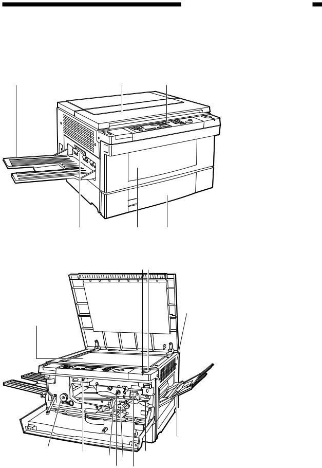
CHAPTER 1 GENERAL DESCRIPTION
III. NAMES OF PARTS
A.External View
Figure 1-301
[2] [3]
[4]
[1]
|
[5] |
|
|
[12] |
[6] |
|
[11] |
|
|
[10] |
[8] |
|
[9] |
[7] |
Figure 1-302
[1]Copy tray
[2]Copyboard cover
[3]Control panel
[4]Cassette
[5]Front cover
[6]Delivery cover
[1]Copyboard glass
[2]Power indicator
[3]Power switch
[4]Right cover
[5]Multifeeder tray
[6]Developing assembly release lever
[7]Developing assembly
[8]Transfer/separation assembly
[9]Primary corona assembly cleaner
[10]Feeder assembly release lever
[11]Copy density knob
[12]Fixing assembly knob
|
COPYRIGHT © 1999 CANON INC. |
CANON NP6317 REV.0 APR. 1999 PRINTED IN JAPAN (IMPRIME AU JAPON) |
1-5 |

CHAPTER 1 GENERAL DESCRIPTION
B.Cross Section
|
[1] |
[2] |
[3] |
[4] |
[5] |
[6] |
[7] |
[8] |
[9] |
[10] |
[11] |
[12] |
[13] |
|
[24] |
[23] |
[22] |
[21] |
[20] |
[19] |
[18] |
[17] |
[16] |
[15] |
[14] |
||||||||
|
[1] |
No. 3 mirror |
[10] No. 6 mirror |
[19] Photosensitive drum |
|||||||||||||||
|
[2] |
No. 2 mirror |
[11] No. 5 mirror |
[20] Cassette |
|||||||||||||||
|
[3] |
No. 1 mirror |
[12] No. 4 mirror |
[21] Feeder assembly |
|||||||||||||||
|
[4] |
Scanning lamp |
[13] Multifeeder tray |
[22] Exhaust fan |
|||||||||||||||
|
[5] Copyboard glass |
[14] Developing assembly |
[23] Fixing assembly |
||||||||||||||||
|
[6] |
Copyboard cover |
[15] Feeder roller 1 |
[24] Delivery roller |
|||||||||||||||
|
[7] |
Lens |
[16] |
Pick-up roller |
|||||||||||||||
|
[8] |
Pre-exposure lamp |
[17] |
Registration roller |
|||||||||||||||
|
[9] |
Primary corona |
[18] Transfer corona |
||||||||||||||||
|
assembly |
assembly |
Figure 1-303
|
1-6 |
COPYRIGHT © 1999 CANON INC. |
CANON NP6317 REV.0 APR. 1999 PRINTED IN JAPAN (IMPRIME AU JAPON) |

CHAPTER 1 GENERAL DESCRIPTION
Blank Page
|
COPYRIGHT © 1999 CANON INC. |
CANON NP6317 REV.0 APR. 1999 PRINTED IN JAPAN (IMPRIME AU JAPON) |
1-7 |

CHAPTER 1 GENERAL DESCRIPTION
IV. OPERATION
A.Control Panel
|
[1] |
[2] |
[3] [4][5] [6] |
[7] |
[8] |
[9] |
[10] |
||||||||||||||||||||||||||||
[22] [21] [20] [17] [16] [15] [14] [13] [12] [11] [19]
[18]
Figure 1-401
|
1-8 |
COPYRIGHT © 1999 CANON INC. |
CANON NP6317 REV.0 APR. 1999 PRINTED IN JAPAN (IMPRIME AU JAPON) |

|
CHAPTER 1 GENERAL DESCRIPTION |
||
|
No. |
Name |
Description |
|
[1] |
Sort/Group key |
Press to select or cancel the Sort or Group mode. |
|
* To use the Sort or Group mode, your copier must be |
||
|
equipped with the optional Sorter or Stapler Sorter. |
||
|
[2] |
Two-Page Separation key |
Press to select or cancel the Two-Page Separation mode. |
|
[3] |
Paper Jam indicator |
Flashes when a paper jam occurs. |
|
[4] |
Control Card Check indicator |
Flashes when the Control Card is not fully inserted. |
|
[5] |
Paper Out indicator |
Flashes when there is no paper in the selected paper sup- |
|
ply (paper cassette or stack bypass). |
||
|
[6] |
Toner Out indicator |
Flashes when toner needs to be added. |
|
[7] |
Copy quantity/Copy ratio display |
Displays the number of copies to be made, and the se- |
|
lected enlargement/reduction ratio. |
||
|
Also, when the copier is not functioning properly, the Ser- |
||
|
vice Call message will appear here. |
||
|
[8] |
Reset key |
Press to return the copier to the Standard mode. |
|
[9] |
Start key |
Press to begin copying. |
|
[10] |
Stop key |
Press to stop the copier before copying is complete. |
|
[11] |
Clear key |
Press to change the number of copies to be made to one. |
|
[12] |
Number keys |
Press to input the number of copies to be made. |
|
[13] |
Percent key |
Press to display the selected enlargement/reduction ratio. |
|
[14] |
Zoom keys |
Press to reduce or enlarge copy images by any ratio from |
|
50% to 200%, selectable in 1% increments. |
||
|
[15] |
Autom. Zoom key |
Press to select or cancel Automatic Zoom. |
|
* To use Automatic Zoom, your copier must be equipped |
||
|
with the optional Automatic Document Feeder (ADF). |
||
|
When copying using the stack bypass or a universal cas- |
||
|
sette, you cannot use Automatic Zoom. |
||
|
[16] |
Paper Select key |
Press to select the paper supply (paper cassette or stack |
|
bypass). |
||
|
[17] |
Paper Supply/Jam Location indica- |
Lights to show the selected paper supply (paper cassette |
|
tor |
or stack bypass). |
|
|
If a paper jam occurs, flashes to show jam location. |
||
|
* This indicator will also flash to inform the user of vari- |
||
|
ous errors. |
||
|
[18] |
Enlarge key |
Press to enlarge copy images using a fixed enlargement |
|
ratio. |
||
|
[19] |
1:1 (Direct) Copy key |
Press to make copies the same size as the original. |
|
[20] |
Reduce key |
Press to reduce copy images using a fixed reduction ratio. |
|
[21] |
AE (Automatic Exposure) key |
Press to select or cancel Automatic Exposure Control. |
|
[22] |
Exposure lever |
Use to manually adjust the lightness/darkness of copies. |
|
COPYRIGHT © 1999 CANON INC. |
CANON NP6317 REV.0 APR. 1999 PRINTED IN JAPAN (IMPRIME AU JAPON) |
1-9 |

CHAPTER 1 GENERAL DESCRIPTION
B.Daily Inspection to Be Performed by the User
Carefully instruct the user to be sure to clean the following parts of the copier once a week.
1.Primary Corona Assembly
Slide in and out the wire cleaner to clean the corona wires.
2.Copyboard Glass
Clean the copyboard glass with a moist cloth; then, wipe it dry.
3.Copyboard Cover
Clean the copyboard cover with a mild detergent solution; then, wipe it dry.
4.Transfer Corona Assembly
Remove the transfer corona assembly from the copier; then, slide the knob (wire cleaner) at the bottom of the transfer corona assembly back and forth to clean the corona wires.
Further, clean the static eliminator using the cleaning brush (accessory).
|
1-10 |
COPYRIGHT © 1999 CANON INC. |
CANON NP6317 REV.0 APR. 1999 PRINTED IN JAPAN (IMPRIME AU JAPON) |

CHAPTER 1 GENERAL DESCRIPTION
V. IMAGE FORMATION
A.Outline
|
Copyboard glass |
|||||||
|
Scanning lamp |
|||||||
|
Lens |
|||||||
|
Primary corona assembly |
Developing |
||||||
|
assembly |
|||||||
|
Pre-exposure lamp |
|||||||
|
Cleaning roller |
Drum cleaner |
Picture to |
be changed |
||||
|
+ |
+ |
(1 register |
station only) |
||||
|
+ |
+ |
||||||
|
+ |
+ |
+ |
|||||
|
Upper fixing roller |
|||||||
|
+ |
|||||||
|
+ |
+ |
||||||
|
+ |
|||||||
|
+ |
Transfer |
corona |
assembly |
||||
|
+ |
|||||||
|
Static |
charge |
+ |
|||||
|
eliminator |
+ |
||||||
|
Upper |
fixing roller |
Figure 1-501
This copier consists of the units shown in Figure 1-501.
The image forming process is divided into the eight steps shown below. Step 1: Pre-exposure
Step 2: Primary corona (negative DC) Step 3: Image exposure
Step 4: Developing (positive plus AC) Step 5: Transfer (negative DC)
Step 6: Separation Step 7: Fixing
Step 8: Drum cleaning
|
Electrostatic latent image formation block |
|||
|
2. Primary corona |
3. Image exposure |
||
|
1. Pre-exposure |
4. Developing |
||
|
8. Drum |
cleaning |
||
|
5. Transfer |
Multifeeder |
||
|
Copy delivery |
6. Separation |
Registration |
|
|
7. Fixing |
Cassette |
||
|
Flow of |
copy paper |
||
|
Direction |
of rotation of drum |
Figure 1-502
|
COPYRIGHT © 1999 CANON INC. |
CANON NP6317 REV.0 APR. 1999 PRINTED IN JAPAN (IMPRIME AU JAPON) |
1-11 |

CHAPTER 2
BASIC OPERATION
In outline diagrams,  represents mechanical drive paths, and
  indicates electrical signal paths.
Signals in digital circuits are identified as ‘1’ for High and ‘0’ for Low. The voltage of signals, however, depends on the circuit.
Nearly all operations of the product are controlled by a microprocessor; the internal workings of the processor are not relevant to the serviceman’s work and, therefore, are left out of the discussions. By the same token, no repairs are prescribed for the PCBs at the user’s premises; for this reason, PCBs are discussed by means of block diagrams rather than circuit diagrams.
For the purpose of explanation, discussions are divided into the following: from sensors to DC controller PCB input ports; from DC controller output ports to loads; and minor control circuits and functions.
|
I. BASIC OPERATION ……………….. |
2-1 |
D. |
DC Controller Outputs ……….. |
2-6 |
|
|
A. |
Functions …………………………. |
2-1 |
E. |
Basic Sequence of Operations |
|
|
B. Outline of Electric Circuitry … |
2-2 |
(Direct, Continuous Copying |
|||
|
C. |
Inputs to DC Controller ……… |
2-4 |
(2 sheets)) ……………………….. |
2-9 |
|
COPYRIGHT © 1999 CANON INC. |
CANON NP6317 REV.0 APR. 1999 PRINTED IN JAPAN (IMPRIME AU JAPON) |

CHAPTER 2 BASIC OPERATION
I. BASIC OPERATION
A.Functions
The copier can be divided into four functional sections: paper pick-up and feed system, exposure system, image formation system, and control system.
|
Control |
system |
|
|
Control |
panel |
|
|
Control |
circuit |
|
Exposure system |
|
|
Copybord |
|
|
Scanner |
|
|
Optical |
|
|
system |
tormation |
|
Image |
|
|
system |
|
|
Pnimary corona |
|
Cleaning unit |
Photosensi- |
|||
|
Developing |
||||
|
tive drum |
||||
|
assembly |
||||
|
Transfer and |
Multifeeder |
|||||
|
separation |
||||||
|
assembly |
Pick-up |
assembly |
||||
|
Paper |
delivery |
Feeder |
control |
|||
|
assembly |
||||||
|
tray |
Copy |
delivery |
||||
|
Fixing |
assembly |
|||||
|
assembly |
Cassette
Paper pick-up and feed system
Figure 2-101
|
COPYRIGHT © 1999 CANON INC. |
CANON NP6317 REV.0 APR. 1999 PRINTED IN JAPAN (IMPRIME AU JAPON) |
2-1 |

CHAPTER 2 BASIC OPERATION
B.Outline of Electric Circuitry
The NP-6317’s main mechanisms are controlled by the microprocessor, PROM, and EEPROM on the DC controller PCB.
1.Microprocessor (Q300)
•controls the copying sequence
•controls the control panel
•controls the main motor/scanner motor/mirror motor
•controls the scanning lamp/fuser lamp
•reads the analog signals
2.PROM (Q301)
•contains the sequence program
3.EEPROM (Q317)
•stores data that can be modified in the service mode (replaces conventional variable resistors and switches)
Note:
EEPROM is a type of ROM in which data may be erased or stored newly.
For this reason, the NP-6317’s RAM and RAM are not backed up by a lithium battery.
Note:
The NP-6317 is equipped with an A/D converter and, therefore, its microprocessor can read analog signals.
Note:
The main motor (M1) is a brushless motor.
The scanner motor (M2) and mirror motor (M3) are stepping motors which use the oscillation frequency of the crystal oscillator on the DC controller.
|
2-2 |
COPYRIGHT © 1999 CANON INC. |
CANON NP6317 REV.0 APR. 1999 PRINTED IN JAPAN (IMPRIME AU JAPON) |

CHAPTER 2 BASIC OPERATION
<Sensors>
Scanner home position sensor Lens home position sendor Cassette paper sensor Delivery paper sensor Pre-registration paper sensor Multifeeder paper densor Mirror home position sensor
Cassette size sensor
Right door switch
AE sensor
Black toner level sensor
Conntrol panel
Thermistors
Sensors, Switches
Sensors, Switches
<Control panel>
DC controller PCB
Microprocenssor (Q300)
PROM (Q301)
EEPROM (Q317)
Driver (Q324)
Microprocessor
Sorter controller PCB
Microprocessor
ADF controller PCB
Figure 2-102
<Loads>
|
Main motor |
||||
|
AC driver/DC |
Fixing roller heater |
|||
|
power supply |
PCB |
|||
HVT
Registration roller clutch
Lens solenoid
Pick-up clutch solenoid
Blank solenoid
Multifeeder solenoid
Primary/Transfer corona assembly
Developing bias
GND bias
|
Lamp regulator |
Scanning lamp |
||
Scanner motor
Mirror motor
Pre-exposure lamp
Exhaust fan
Scanner cooling fan
Sorter
ADF
|
COPYRIGHT © 1999 CANON INC. |
CANON NP6317 REV.0 APR. 1999 PRINTED IN JAPAN (IMPRIME AU JAPON) |
2-3 |

CHAPTER 2 BASIC OPERATION
C.Inputs to DC Controller
1.Inputs to DC Controller (1/2)
Q1
Multifeeder paper sensor
Q2
Pre-registration paper sensor
Q3
Right door sensor
Q4
Mirror home position sensor
Q5
Scanner home position sensor
Q6
Lens home position sensor
Q7
Cassette paper sensor
Q8
Delivery paper sensor
|
DC controller PCB |
||||||||||
|
J24-1 |
J311-5 |
5V |
||||||||
|
-2 |
-4 |
when |
paper is over |
Q1, «1» |
||||||
|
MFPD |
(light-blocking |
plate |
is |
at |
Q1) |
|||||
|
-3 |
-3 |
|||||||||
|
J23-1 |
J304-9 |
5V |
||||||||
|
-2 |
-8 |
when |
paper is at Q2, «1» |
|||||||
|
PRP |
(light-blocking |
plate |
is |
at |
Q2) |
|||||
|
-3 |
-7 |
|||||||||
|
J27-1 |
J311-8 |
5V |
||||||||
|
when |
night door is |
closed, «1» |
||||||||
|
-2 |
-7 |
|||||||||
|
RDC |
(light-blocking |
plate |
is |
at |
Q3) |
|||||
|
-3 |
-6 |
|||||||||
|
J801-1 |
J312-3 |
5V |
||||||||
|
-2 |
-2 |
when |
mirror motor |
is |
at |
home |
position, «1» |
|||
|
MHP |
(light-blocking |
plate |
is |
at |
Q4) |
|||||
|
-3 |
-1 |
|||||||||
|
J35-1 |
J312-6 |
5V |
||||||||
|
-2 |
-5 |
when |
scanner |
is at |
home position, «1» |
|||||
|
SCHP |
(light-blocking |
plate |
is |
at |
Q5) |
|||||
|
-3 |
-4 |
|||||||||
|
J33-1 |
J312-9 |
5V |
||||||||
|
-2 |
-8 |
when |
lens is at home |
position, «1» |
||||||
|
LHP |
(light-blocking |
plate |
is |
at |
Q6) |
|||||
|
-3 |
-7 |
|||||||||
|
J26-1 |
J303-7 |
5V |
||||||||
|
-2 |
-6 |
when |
paper is in cassette, «1» |
|||||||
|
CPEP |
(light-blocking |
plate |
is |
at |
Q7) |
|||||
|
-3 |
-5 |
|||||||||
|
J44-1 |
J314-5 |
5V |
||||||||
|
-3 |
-3 |
when |
paper is at Q8, «0» |
|||||||
|
DLP |
(light-blocking |
plate |
is |
not at Q8) |
||||||
|
-2 |
-4 |
|||||||||
|
Figure 2-103 |
|
2-4 |
COPYRIGHT © 1999 CANON INC. |
CANON NP6317 REV.0 APR. 1999 PRINTED IN JAPAN (IMPRIME AU JAPON) |

CHAPTER 2 BASIC OPERATION
2.Inputs to DC Controller (2/2)
AE sensor
Black toner leveol sensor
Thermistor 2 (auxiliary)
Thermistor 1 (main)
Cassette size sensor
|
DC controller PCB |
||||||||||||||||||||||||||
|
AE |
24V |
|||||||||||||||||||||||||
|
J701-4 |
J312-13 |
|||||||||||||||||||||||||
|
24V |
||||||||||||||||||||||||||
|
-2 |
-11 |
AE |
||||||||||||||||||||||||
|
— |
See p. 3-25 |
|||||||||||||||||||||||||
|
+ |
-1 |
-10 |
AEGIN |
|||||||||||||||||||||||
|
-3 |
-12 |
|||||||||||||||||||||||||
|
TS1 |
J39-3 |
J303-3 |
5V |
|||||||||||||||||||||||
|
-2 |
-2 |
|||||||||||||||||||||||||
|
BTEP |
||||||||||||||||||||||||||
|
-1 |
-1 |
|||||||||||||||||||||||||
|
J45-1 |
J317-1 |
|||||||||||||||||||||||||
|
TH2 |
||||||||||||||||||||||||||
|
TH2 (NTC2) |
||||||||||||||||||||||||||
|
-2 |
-2 |
|||||||||||||||||||||||||
|
TH1(NTC1) |
The voltage lowers as the fixing |
|||||||||||||||||||||||||
|
-4 |
J317-4 |
TH1 |
heater |
temperature |
rises. |
|||||||||||||||||||||
|
-3 |
-3 |
|||||||||||||||||||||||||
|
CST(SW3) |
||||||||||||||||||||||||||
|
J28-3 |
J313-2 |
CSZ1 |
||||||||||||||||||||||||
|
-4 |
-3 |
|||||||||||||||||||||||||
|
CSZ2 |
||||||||||||||||||||||||||
|
-5 |
-4 |
CSZ3 |
Reads |
the cassette |
size; see p. 3-32. |
|||||||||||||||||||||
|
-6 |
-5 |
CSZ4 |
||||||||||||||||||||||||
|
-2 |
-1 |
oscillation |
signal |
|||||||||||||||||||||||
Figure 2-104
|
COPYRIGHT © 1999 CANON INC. |
CANON NP6317 REV.0 APR. 1999 PRINTED IN JAPAN (IMPRIME AU JAPON) |
2-5 |

CHAPTER 2 BASIC OPERATION
D.DC Controller Outputs
1.DC Controller Out Puts (1/3)
Noise
filter DS1
SW1
Control panel PCB
24V
J509-1
DC controller PCB
|
Power supply |
||||||||||
|
assembly |
J316-11 |
PWOFF |
when «0» |
AC power OFF (main |
||||||
|
24V |
||||||||||
|
switch). |
||||||||||
|
K100 |
||||||||||
|
J318-3 |
HTPT |
when «0» |
AC power OFF (power |
|||||||
|
supply unit). |
||||||||||
|
Fixing roller heater |
Fixing heater |
-2 |
HTCK |
when «0» |
fixing roller heater ON. |
|||||
|
ON detection |
||||||||||
|
J4-1 |
||||||||||
|
circuit |
||||||||||
|
LA1 |
Fixing |
|||||||||
|
-2 |
-1 |
|||||||||
|
heater drive |
HTRD |
when «1» |
fixing roller heater ON. |
|||||||
|
F1 |
||||||||||
|
circuit |
||||||||||
|
Thermoswitch 1 |
||||||||||
|
J201-1 |
J203 |
J305 |
24V |
|||||||
|
-1 |
-6 |
|||||||||
|
Scanning lamp |
F2 |
-2 |
-4 |
-3 |
LAMP-CHECK |
|||||
|
-5 |
-2 |
|||||||||
|
J202-3 |
Lamp driver unit |
ZERO-CROSS |
See p. 3-20. |
|||||||
|
LA2 |
Thermoswitch 2 |
-1 |
-3 |
-4 |
||||||
|
LIGHT |
||||||||||
|
-2 |
-5 |
|||||||||
|
-6 |
-1 |
LAMP-SHIFT |
||||||||
|
Scanner motor |
M2 |
See |
p. 3-9. |
|||||||
|
Mirror motor |
M3 |
See |
p. 3-9. |
|||||||
|
J351-1 |
J301-1 |
MMLOCK |
when «0» |
main motor is moving. |
||||||
|
-2 |
-2 |
MMD |
when «1» |
main motor ON. |
||||||
|
Main motor |
M1 |
|||||||||
|
-3 |
-3 |
|||||||||
|
-4 |
-4 |
+24V |
||||||||
|
Figure 2-105 |
|
2-6 |
COPYRIGHT © 1999 CANON INC. |
CANON NP6317 REV.0 APR. 1999 PRINTED IN JAPAN (IMPRIME AU JAPON) |

CHAPTER 2 BASIC OPERATION
2.DC Controller Outputs (2/3)
DC controller PCB
|
Pick-up clutch |
solenoid |
24V |
|||
|
J307-5 |
|||||
|
SL1 |
-6 |
PUSD |
|||
|
Lens |
drive |
solenoid |
24V |
||
|
J309-1 |
|||||
|
SL2 |
-2 |
LNSD |
|||
|
Multifeeder |
solenoid |
24V |
|||
|
J311-9 |
|||||
|
SL3 |
-10 |
MFSD |
|||
|
Blank |
solenoid |
24V |
|||
|
J307-7 |
|||||
|
SL4 |
-8 |
BLSD |
|||
|
Registration |
roller |
clutch |
24V |
||
|
J307-3 |
|||||
|
CL1 |
-4 |
RGCD |
|||
|
Figure 2-106 |
when «0», SL1 ON.
when «0», SL2 ON.
when «0», SL3 ON.
when «0», SL4 ON.
when «0», CL1 ON.
|
COPYRIGHT © 1999 CANON INC. |
CANON NP6317 REV.0 APR. 1999 PRINTED IN JAPAN (IMPRIME AU JAPON) |
2-7 |

CHAPTER 2 BASIC OPERATION
3.DC Controller Outputs (3/3)
DC controller PCB
|
J309-1 |
24V |
|||||
|
Scanner cooling fan |
FM1 |
-2 |
FM1D |
|||
|
J311-1 |
24V |
|||||
|
Exhaust fan |
FM2 |
-3 |
FM2D |
|||
|
Pre-exposure lamps |
J731 |
J307 |
24V |
|||
|
-2 |
-1 |
|||||
|
-1 |
-2 |
PEXP |
||||
|
J314-2 |
24V |
|||||
|
Total |
counter |
CNT1 |
-1 |
TCNTD |
||
|
Control panel PCB |
||||||
|
CCV |
5V |
|||||
|
J504-2 |
||||||
|
-4 |
J503-11 |
J316-1 |
CCNTC |
|||
|
-3 |
J503-10 |
-2 |
CCNNT |
|||
|
-1 |
||||||
|
Power indicator |
J501 |
J315 |
||||
|
PCB |
5V |
J502 |
||||
|
J505-1 |
J503 |
J316 |
||||
|
-2 |
||||||
|
Density volume |
5V |
|||||
|
PCB |
J506-3 |
|||||
|
-2 |
J501-1 |
J315-10 |
DNST |
|||
|
-1 |
||||||
|
VR501 |
||||||
|
H V T |
||||||
|
Figure 2-107 |
when «0»  FM1 ON
when «0»  FM2 ON
when «0»  Pre-exposure lamps ON
when «0»  Total counter operates
When «0» Operates.
When «0» Card sensed.
The voltage changes according to the volume setting.
See p. 4-5.
|
2-8 |
COPYRIGHT © 1999 CANON INC. |
CANON NP6317 REV.0 APR. 1999 PRINTED IN JAPAN (IMPRIME AU JAPON) |

CHAPTER 2 BASIC OPERATION
E.Basic Sequence of Operations (Direct, Continuous Copying (2 sheets))
|
WMUPR |
|||||||||||||||||||||||||||||
|
POWER SWITCH 90 C |
110 C COPY START key |
SCRV |
|||||||||||||||||||||||||||
|
ON |
ON |
SCRV |
|||||||||||||||||||||||||||
|
WMUP |
STBY |
INTR |
SCFW |
SCFW |
LSTR |
STBY |
|||||||||||||||||||||||
|
AER |
|||||||||||||||||||||||||||||
|
Main motor(M1) |
|||||||||||||||||||||||||||||
|
Scanning lamp |
|||||||||||||||||||||||||||||
|
Primary/transfer |
|||||||||||||||||||||||||||||
|
corona assembly |
|||||||||||||||||||||||||||||
|
Scanner is set for |
Forward |
||||||||||||||||||||||||||||
|
Scanner movement |
HOME position |
Reverse |
|||||||||||||||||||||||||||
|
* Numbers in parentheses apply to |
|||||||||||||||||||||||||||||
|
when the CT unit is used. |
|||||||||||||||||||||||||||||
|
Figure 2-108 |
|||||||||||||||||||||||||||||
|
Period |
Purpose |
Remarks |
|||||||||||||||||||||||||||
|
WMUP |
From switch on until the |
Allows time for fixing |
Warm-up time varies |
||||||||||||||||||||||||||
|
(Warm-up) |
fixing roller temperature |
roller to warm up. |
with fixing roller tem- |
||||||||||||||||||||||||||
|
reaches 155°C. |
perature at power ON. |
||||||||||||||||||||||||||||
|
When the COPY START |
|||||||||||||||||||||||||||||
|
key lights green. |
|||||||||||||||||||||||||||||
|
WMUPR |
Until the fixing roller |
Keeps fixing roller tem- |
• After the WMUPR pe- |
||||||||||||||||||||||||||
|
(Warm-up |
temperature reaches 90°C |
perature uniform. |
riod ends, the READY/ |
||||||||||||||||||||||||||
|
rotation) |
to 110°C for the. |
WAIT indicator changes |
|||||||||||||||||||||||||||
|
from flashing green to |
|||||||||||||||||||||||||||||
|
green. |
|||||||||||||||||||||||||||||
|
• Even when the fixing |
|||||||||||||||||||||||||||||
|
roller has warmed up, it |
|||||||||||||||||||||||||||||
|
rotates for at least 4.2 |
|||||||||||||||||||||||||||||
|
sec. |
|||||||||||||||||||||||||||||
|
INTR |
About 2.2 sec after the |
Stabilizes drum sensitiv- |
A PAPER FEED signal is |
||||||||||||||||||||||||||
|
(INITIAL |
COPY START key is |
ity to prepare for copying. |
generated to feed first |
||||||||||||||||||||||||||
|
rotation) |
pressed. |
sheet of copy paper. |
|||||||||||||||||||||||||||
Table 2-101a
|
COPYRIGHT © 1999 CANON INC. |
CANON NP6317 REV.0 APR. 1999 PRINTED IN JAPAN (IMPRIME AU JAPON) |
2-9 |

CHAPTER 2 BASIC OPERATION
|
Period |
Purpose |
Remarks |
|
|
AER |
From when the scanner |
Moves the scanner for- |
In the non-AE mode the |
|
(AE rotation) |
moves forward about 70 |
ward about 70 mm from |
scanner does not move |
|
mm from the end of the |
the end of the image and |
forward or in reverse. |
|
|
image until it returns to |
measures the document |
||
|
its home position. |
density. |
||
|
SCFW |
When the scanner is mov- |
The scanning lamp illu- |
• A REGISTRATION sig- |
|
(Scanner |
ing forward |
minates original, and the |
nal is generated, and |
|
forward) |
• Travel distance changes |
reflected optical image is |
copy paper is fed to the |
|
with copy paper size. |
transmitted to photo- |
transfer area. |
|
|
sensitive drum through |
• A PAPER FEED signal |
||
|
mirrors and lens array. |
is generated to feed the |
||
|
next sheet of copy paper. |
|||
|
SCRV |
While the scanner is mov- |
The scanner is moved |
|
|
(Scanner |
ing in reverse. |
back to HOME position |
|
|
reverse) |
• The speed of the reverse |
to prepare for the next |
|
|
movement is 2.5 times |
copy. |
||
|
that of the forward |
|||
|
movement. |
|||
|
LSTR |
Until the main motor |
Ensures full discharge of |
|
|
(LAST rotation) |
stops after SCRV until |
the last copy. |
|
|
the last copy ends. |
|||
|
STBY |
Waits until the COPY |
||
|
(Stand-by) |
START key is pressed. |
||
Table 2-101b
|
2-10 |
COPYRIGHT © 1999 CANON INC. |
CANON NP6317 REV.0 APR. 1999 PRINTED IN JAPAN (IMPRIME AU JAPON) |

CHAPTER 3
EXPOSURE SYSTEM
1.Disconnect the power cord for safety before disassembly or reassembly work.
2.Group the screws by type (length and diameter) and location.
3.The mounting screws are equipped with washers to protect against static electricity; do not leave them behind when attaching the covers.
4.The mounting screw for the grounding wire is equipped with a washer to ensure electrical continuity; make sure that the washer is attached to the screw when removing/fitting it.
5.If possible, avoid operating the machine with any of its parts removed.
6.Unless otherwise noted, re-assembly is the reverse of disassembly.
|
I. BASIC OPERATION ………………. |
3-1 |
D. Scanner Movement for |
|
|
A. Changing the Reproduction |
Two-Page Separation Mode |
||
|
Ratio ……………………………….. |
3-1 |
(copy count «2») ………………… |
3-7 |
|
II. LENS DRIVE SYSTEM ……………. |
3-2 |
IV. |
No. 4/5 MIRROR DRIVE |
|||
|
A. |
Outline …………………………….. |
3-2 |
SYSTEM ……………………………….. |
3-8 |
||
|
B. Basic Lens Drive System |
V. |
DISASSEMBLY AND |
||||
|
Operation (change of |
ASSEMBLY …………………………. |
3-11 |
||||
|
reproduction ratio) …………….. |
3-3 |
A. |
Lens Drive Assembly ……… |
3-11 |
||
|
III. SCANNER DRIVE SYSTEM ……. |
3-4 |
B. |
Scanner Drive Assembly …. |
3-14 |
||
|
A. |
Outline …………………………….. |
3-4 |
C. |
Exposure Assembly ……….. |
3-17 |
|
|
B. |
Relation Between Scanner |
D. |
Blank Assembly ……………… |
3-19 |
||
|
Sensor and Signals …………… |
3-5 |
E. |
No. 4/5 Mirror Mount……….. |
3-20 |
||
|
C. |
Basic Scanner Operation …… |
3-6 |
|
COPYRIGHT © 1999 CANON INC. |
CANON NP6317 REV.0 APR. 1999 PRINTED IN JAPAN (IMPRIME AU JAPON) |

CHAPTER 3 EXPOSURE SYSTEM
I.BASIC OPERATION
A.Changing the Reproduction Ratio
The reproduction ratio across the drum is varied by changing the position of the lens and the position of No. 4 and No. 5 mirrors. It is moved by the lens drive system. The reproduction ratio around the drum is varied by changing the speed of the scanner. Figure 3-101 shows how the position of the lens and mirror is varied to change the reproduction ratio across the drum.
100%
50%
200%
Figure 3-101
The scanner drive system changes the reproduction ratio around the drum by varying the speed at which mirror 1 moves relative to the peripheral speed of the drum. (The scanner consists of mirror 1 and the scanning lamp.)
The mirror speed is higher than the drum peripheral speed for REDUCTION and lower for ENLARGEMENT.
Note:
For DIRECT copying, the speed of the mirror is the same as the peripheral speed of the drum.
|
COPYRIGHT © 1999 CANON INC. |
CANON NP6317 REV.0 APR. 1999 PRINTED IN JAPAN (IMPRIME AU JAPON) |
3-1 |

CHAPTER 3 EXPOSURE SYSTEM
II. LENS DRIVE SYSTEM
A.Outline
The lens is moved by the scanner motor (M2). Normally, the coupling gear is in its upper position, and connects the scanner motor to the scanner drive capstan. To move the lens, the lens solenoid (SL2) goes ON, causing the coupling gear to disengage from the scanner capstan gear and engage with the lens capstan gear. The lens is a «floating element» type. In operation, the relative position of lens elements (individual lenses) changes, and the focal length changes as a result, but the changes are intended to optimize lens sharpness for each reproduction ratio, not to make the lens function as a zoom lens. (The lens should not be dismantled.)
When the scanner motor rotates (CW), the lens will be moved to the left (for ENLARGEMENT) by the capstan and cable.
When the paper size is changed or when the copier is in the REDUCE mode, the blank exposure shutter moves in relation to the distance over which the lens travels, thereby blanking out the width corresponding to the reproduction ratio.
The DC controller indicates ‘E210’ on the control panel in response to an error in the lens drive system.
Couping gear
Scanner drive capstan
Solenoid «ON»
Scanner motor (M2)
SL2
Lens drive cable

 Idler gear
Q4 
Lens
|
SOLENOIDLENS (LNSD)commandDRIVE |
POSITIONHOMELENS (LHP)signal |
ENLARGEMENT direction
DC contoroller PCB
Figure 3-201
|
3-2 |
COPYRIGHT © 1999 CANON INC. |
CANON NP6317 REV.0 APR. 1999 PRINTED IN JAPAN (IMPRIME AU JAPON) |

CHAPTER 3 EXPOSURE SYSTEM
B.Basic Lens Drive System Operation (change of reproduction ratio)
|
copy start |
|||
|
key ON |
|||
|
STAND BY |
INITIAL ROTATION |
SCAN FORWARD |
|
|
AE ROTATION |
|||
Scanner home position sensor (Q5)
Scanner motor (M2)
Scanner movement
Lens solenoid (SL2)
Lens movement
Lens home position sensor (Q6)
Mirror home position sensor (Q4)
Mirror movement
: Forward : Reverse
Figure 3-202
When the paper size is changed or when the copier is in the ZOOM mode, the lens first returns to the home position before moving to the position that corresponds to the cassette size and the reproduction ratio.
This operation is executed also when the ZOOM mode is switched to the DIRECT mode.
|
COPYRIGHT © 1999 CANON INC. |
CANON NP6317 REV.0 APR. 1999 PRINTED IN JAPAN (IMPRIME AU JAPON) |
3-3 |

CHAPTER 3 EXPOSURE SYSTEM
III. SCANNER DRIVE SYSTEM
A.Outline
The scanner is driven by the scanner motor (M2). The direction of rotation of the scanner motor determines whether the scanner moves forward or backward. The forward speed of the scanner motor is continuously variable to produce the required reproduction ratio. The reverse speed is fixed regardless of the reproduction ratio (2.5 times the forward speed for DIRECT copying).
The distance that the scanner moves varies to suit the size of copy paper and the reproduction ratio.
The control panel displays ‘E202’ in response to an error in the scanner motor (M2) or the scanner home position sensor (Q5).
Mirror 2 mount
Mirror 1 mount
Forward
Signal generating plate
Scanner home position sensor (Q5)
|
Connecting |
gear |
(SCHP) |
|
|
Lens gear |
signal |
||
|
SL2 |
position |
||
|
LENS DRIVESOLENOID (LNSL)command |
Scannerhome |
||
|
Scanner motor (M2) |
|||
|
Solenoid |
«OFF»
|
A |
J302-5 |
|||||
|
COM-A |
-4 |
|||||
|
A |
-6 |
|||||
|
B |
-2 |
|||||
|
COM-B |
-1 |
|||||
|
B |
-3 |
|||||
|
driver (Q324) |
controller |
PCB |
|
Motor |
DC |
|
Figure 3-301
|
3-4 |
COPYRIGHT © 1999 CANON INC. |
CANON NP6317 REV.0 APR. 1999 PRINTED IN JAPAN (IMPRIME AU JAPON) |

CHAPTER 3 EXPOSURE SYSTEM
B.Relation Between Scanner Sensor and Signals
|
Scanner sensor |
Signal name |
Scanner |
||||||||
|
Forward |
Reverse |
|||||||||
|
Scanner home |
SCHP |
|||||||||
|
position sensor |
||||||||||
|
(Q5) |
||||||||||
Meaning
•Grid bias ON
•After 0.1 sec, the scanner stops advancing.
Table 3-301
|
COPYRIGHT © 1999 CANON INC. |
CANON NP6317 REV.0 APR. 1999 PRINTED IN JAPAN (IMPRIME AU JAPON) |
3-5 |

CHAPTER 3 EXPOSURE SYSTEM
C.Basic Scanner Operation
|
POWER switch ON |
COPY START key ON |
|
|
WMUP |
STBY INTR |
SCFW SCRV SCFW SCRV LSTR |
|
AER |
Scanner home position sensor (Q5)signal
Pre-registration paper sensor (Q2) signal
Forward Reverse
Scanner movement
Scanning lamp
Figure 3-302
|
3-6 |
COPYRIGHT © 1999 CANON INC. |
CANON NP6317 REV.0 APR. 1999 PRINTED IN JAPAN (IMPRIME AU JAPON) |

CHAPTER 3 EXPOSURE SYSTEM
D.Scanner Movement for Two-Page Separation Mode (copy count «2»)
|
Doc.L.E. |
Doc.L.E. |
Doc.L.E. |
Doc.L.E. Doc.L.E. Doc.L.E. |
|||||||||||||||||||||||||||||||
|
INTR |
(1st page) |
(1st page) |
(1st page)(2st page) (1st page) (2st page) |
|||||||||||||||||||||||||||||||
|
SCRV1 |
SCRV1 |
SCRV2 |
SCRV2 |
STBY |
||||||||||||||||||||||||||||||
|
SCFW1 |
SCFW1 |
SCFW2 |
SCFW2 |
LSTR |
||||||||||||||||||||||||||||||
Scanner home position sensor signal (Q5)
SCANNER FORWARD command (SCFW)
SCANNER REVERSE command (SCRV)
Scanning lamp (LA1)
 Forward
 Forward
 Forward
  Forward
|
Reverse |
Reverse |
Reverse |
Reverse |
Figure 3-303
Timing of operations, i.e., I, II, and III shown in Figure 3-304, is with reference to the leading edge of the first page of the document (fall of Q3 signal).
I:The distance traveled by the scanner from the leading edge of the original is determined by the reproduction ratio and the copy paper size, just as for a normal copy.
II:This is roughly the same as I. If the forward distance traveled by the scanner is greater than 210 mm (220V, or 240V copier) the DC controller will judge that 210 mm is the leading edge of the original. If the distance that the scanner moves forward is less than 210 mm, the point at which the scanner reverses in I will be the leading edge of the second page of the document.
III: Same as I.
|
COPYRIGHT © 1999 CANON INC. |
CANON NP6317 REV.0 APR. 1999 PRINTED IN JAPAN (IMPRIME AU JAPON) |
3-7 |

CHAPTER 3 EXPOSURE SYSTEM
IV. No. 4/5 MIRROR DRIVE SYSTEM
1.Outline
The copier changes the reproduction ratio by varying the position of the No. 4/5 mirror and moving the lens. Figure 3-401 shows the positions of the mirror and the lens according to different reproduction ratios.
The mirror is driven by the mirror motor (M3), and its position is monitored by the mirror home position sensor (Q4). The mirror is positioned with reference to the number of motor pulses counted from the mirror home position.
When the power is turned on, the mirror motor (M3) continues to rotate clockwise until the mirror home position sensor (Q4) turns on. Thereafter, it rotates counterclockwise for a specific number of pulses to stop the No. 4/5 mirror at Direct position.
When a non-Direct ratio is selected during standby, both mirror and lens are driven accordingly.
Mirror motor (M3)
Mirror
home position sensor (Q4)
|
Enlargement / |
|
|
Direct |
Reduction |
Figure 3-401
|
3-8 |
COPYRIGHT © 1999 CANON INC. |
CANON NP6317 REV.0 APR. 1999 PRINTED IN JAPAN (IMPRIME AU JAPON) |

CHAPTER 3 EXPOSURE SYSTEM
2.Driving the Scanner Motor (M2) and the Mirror Motor (M3)
Figure 3-402 is a block diagram showing the drive circuit used for the scanner motor (M2) and the mirror motor (M3). These motors are 4-phase stepping motors.
The pulse signals used to drive the motors (MIRRA, MIRRA*, MIRRB, MIRRB*) are generated by Q300 of the DC controller PCB; on the other hand, the motor select signal (MIRRCOM, SCNCOM) is generated by Q300 and Q303.
The motor selected by the motor select signal is controlled for direction and speed by the pulse signals from Q300.
|
DC controller PCB |
||||||
|
24V |
||||||
|
Q300 |
Q320 |
Q319 |
||||
|
(CPU) |
MIRRCOM |
|||||
|
MIRRA |
Q323 |
5V |
Mirror |
|||
|
J303 |
||||||
|
Q325 |
MIRRA |
motor |
||||
|
5V |
5 |
|||||
|
MIRRA* |
Q326 |
COM |
3 |
M3 |
||
|
Q325 |
||||||
|
MIRRA* |
||||||
|
5V |
4 |
|||||
|
MIRRB |
Q327 |
Q325 |
MIRRB |
|||
|
2 |
||||||
|
5V |
MIRRB* |
|||||
|
MIRRB* |
Q328 |
Q325 |
1 |
|||
|
5V |
5V |
|||||
|
Q329 |
Q330 |
|||||
|
Q371 |
Q370 |
|||||
|
TDA |
TDB |
|||||
|
Q324 |
||||||
|
Scanner motor |
Scanner |
|||||
|
driver |
J302 |
|||||
|
24V |
PMA |
motor |
||||
|
Q365 |
Q321 |
5 |
||||
|
Q303 |
||||||
|
SCNCOM |
||||||
|
COM |
||||||
|
4 |
M2 |
|||||
|
PMA* |
6 |
|||||
|
PMB |
2 |
|||||
|
COM |
||||||
|
1 |
||||||
|
PMB* |
||||||
|
3 |
||||||
|
Figure 3-402 |
|
COPYRIGHT © 1999 CANON INC. |
CANON NP6317 REV.0 APR. 1999 PRINTED IN JAPAN (IMPRIME AU JAPON) |
3-9 |

CHAPTER 3 EXPOSURE SYSTEM
|
100% to |
70% to |
50% to |
|
70% |
50% |
200% |
|
setting |
setting |
setting |
Scanner motor (M2)
Lens HP sensor (Q6)
Mirror motor (M3)
Mirror HP sensor (Q4)
|
:motor foward |
:motor reverce |
Figure 3-403
|
3-10 |
COPYRIGHT © 1999 CANON INC. |
CANON NP6317 REV.0 APR. 1999 PRINTED IN JAPAN (IMPRIME AU JAPON) |

CHAPTER 3 EXPOSURE SYSTEM
V. DISASSEMBLY AND ASSEMBLY
A.Lens Drive Assembly
1.Outline
The unit is adjusted at the factory with high precision using special tools. Do not remove parts or loosen screws other than those discussed.
Lens pully
Lens pully
fixing plate
[2]
4 turns
Mounting screws
[3]
Cable fixing
Pulley mount
Figure 3-501
|
COPYRIGHT © 1999 CANON INC. |
CANON NP6317 REV.0 APR. 1999 PRINTED IN JAPAN (IMPRIME AU JAPON) |
3-11 |

CHAPTER 3 EXPOSURE SYSTEM
2.Detaching the Lens Cable
|
1) |
Detach the copyboard cover, copyboard |
|
|
glass, lens cover, rear cover, and upper |
||
|
rear cover. |
||
|
2) |
Remove the three screws shown in Figure |
[1] |
|
3-502, and detach the upper frame. |
[1] Screws
Figure 3-502
3)Mark the position of the pulley mount and the cable mount using a scriber.
4)Remove the two screws that hold the pulley mount in place.
5)Detach the cable.
|
3-12 |
COPYRIGHT © 1999 CANON INC. |
CANON NP6317 REV.0 APR. 1999 PRINTED IN JAPAN (IMPRIME AU JAPON) |

CHAPTER 3 EXPOSURE SYSTEM
3.Routing the Lens Cable
|
1) Remove the two screws that hold the lens |
|
|
pulley mount in place, and detach the lens |
[2] |
|
pulley; see Figure 3-501. |
[1] |
[3]
|
[1] |
Screws |
[2] Pulley |
|
[3] |
Pulley mount |
Figure 3-503
2)Wind the lens cable around the lens pulley as shown in Figure 3-504; then, fix it using two screws.
3)Shift the pulley mount to the position marked with a scriber, and fix it in place using two screws.
|
COPYRIGHT © 1999 CANON INC. |
CANON NP6317 REV.0 APR. 1999 PRINTED IN JAPAN (IMPRIME AU JAPON) |
3-13 |

CHAPTER 3 EXPOSURE SYSTEM
B.Scanner Drive Assembly
1.Detaching the Scanner Cable
1)Mark the position of the mount, and loosen screws B (2 pcs.), which hold the mount in place.
2)Loosen screw A (1 pcs.), and detach the scanner cable.
2.Attaching the Scanner Cable
1)Route the scanner cable as shown in Figure 3-504.
2)Position the fixing plate where a mark has been put using screw A.
3)Tighten screws B.
[6]
[2]
Top groove of the pulley
Lower groove of the pulley
Scanner pulley

 [4] [1]


[3]
Pulley 2
Mark the position
Figure 3-504 Scanner Drive Assembly
|
3-14 |
COPYRIGHT © 1999 CANON INC. |
CANON NP6317 REV.0 APR. 1999 PRINTED IN JAPAN (IMPRIME AU JAPON) |
 Loading…
More products and manuals for Copiers Canon
| Models | Document Type |
|---|---|
|
IR2016 |
User Manual
6 pages |
|
imageRUNNER 6000i |
User Manual
7 pages |
|
Image Runner iRC1028i |
User’s Guide
15 pages |
|
FAX-B155 |
User’s Guide
141 pages |
|
Color ImageRUNNER C2058 |
User Manual
24 pages |
|
IR2016 |
User’s Guide
124 pages |
|
DADF-Q1 |
User Manual
6 pages |
|
imageRUNNER 3300 |
Setup Guide
129 pages |
|
Color imageRUNNER C4080i |
User Manual
8 pages |
|
MP980 series |
Instruction Manual
71 pages |
|
imageRUNNER 1740i |
User Manual
8 pages |
|
NP7130F |
Specifications
426 pages |
|
PSC 2000 |
Technical Information
82 pages |
|
imageCLASS MF6500 Series |
User Manual
16 pages |
|
Color imageRUNNER C4080i |
User Manual
8 pages |
|
PC890 |
User’s Guide
244 pages |
|
imageRUNNER 2800 |
User Manual
65 pages |
|
PC960 |
Specifications
393 pages |
|
FB636U |
User’s Guide
89 pages |
|
NP6551 |
Operator’s Manual
228 pages |

Your Donation Will Be Matched 1-to-1! Can You Chip In?
Dear Patron: Please don’t scroll past this. The Internet Archive is a nonprofit fighting for universal access to quality information. We build and maintain all our own systems, but we don’t charge for access, sell user information, or run ads. Instead, we’re powered by online donations averaging about $14. We’d be deeply grateful if you’d join the one in a thousand users that support us financially.
Right now, we have a matching gift campaign that will double the impact of every donation. We understand that not everyone can donate right now, but if you can afford to contribute this Wednesday, we promise it will be put to good use. Our resources are crucial for knowledge lovers everywhere—so if you find all these bits and bytes useful, please pitch in.
Your Donation Will Be Matched! Can You Chip In?
Dear Patron: Please don’t scroll past this. Right now we have a matching gift campaign that will double the impact of every donation. We understand that not everyone can give right now, but if you can afford to contribute this Wednesday, we promise it will be put to good use. If you find all these bits and bytes useful, please pitch in.