
Опубликовано: | 23 марта, 2022
-
Версия
-
Скачать
131 -
Размер файла
2.17 MB -
Количество файлов
1 -
Дата создания
23.03.2022 -
Последнее обновление
24.03.2022
КамАЗ 5490 NEO. Инструкция по техническому обслуживанию и ремонту
Содержание:
- Инструмент и принадлежности.
- Расходные материалы.
- Комплектующие для ТО.
- Средства индивидуальной защиты (СИЗ).
- Подготовка автомобиля.
- Проверка на герметичность.
- Замена фильтрующего элемента в фильтре высокого давления.
- Замена фильтрующего элемента в фильтре низкого давления.
- Замена редуктора высокого давления.
- Замена блока газовых форсунок.
- Замена РТИ комплекта ГДС.
- Справочник нормо-часов.
- Приложения.
Attached Files
| Файл | |
|---|---|
| kamaz-5490-neo-instrukciya-po-tekhnicheskomu-obsluzhivaniyu-i-remontu-komponentov-sistemy-gazodizelnogo-pitaniya-ecomotive-solutions-emer.pdf |
© 1999-2022: ООО «АльфаАвтоГаз», Все права защищены. Копирование материалов с письменного разрешения администратора!
-
KAMAZ 5490 8 6.2 HEATNG OPERATION IN HIGH GROUND • Heating operation is possible at a height up to 1500 m above sea level. Otherwise, adjustment of device is necessary. Heating operation at a height of 1500-3000 m above sea level without adjustment of the heater is possi- ble for a short time (for example, during a pass crossing or a stop). If you stay for a long time at these altitudes above the sea level, you need to adjust the heater by altitude by installing air pressure sensor that is included with the kit for use at high altitudes. Installation of the kit should be done by an authorized
-
KAMAZ 5490 1 Pramotronic Production Company (Copy) ELTRA TERMO OPEN JOINT STOCK COMPANY «ELTRA TERMO» 1 Introduction This instruction manual (IM) is assigned for study of the structure, operation, assembly and regular maintenance of the heater «PRAMOTRONIC 16WD24» (further referred to as the heater). The diesel heater of 16WD24.8106.000 model with the nominal voltage 24V is designated for pre- starting heat and automatic keeping of thermal conditions of а liquid cooling diesel motor for all makes of trucks, as well as for heating and automatic keeping of te
-
KAMAZ 5490 4-53 IDLE SPEED ADJUSTMENT After engine start up the idle speed is set automati- cally depending on coolant temperature. Idle speed of the engine warmed up to operation temperature is approximately 600 min -1 . The engine idle speed is to be adjusted on a steady vehicle. The idle speed adjustment may be performed with the help of fuel feed control pedal as well as with the but- tons located on the steering wheel, r.h. side (see Fig. Steering wheel). In contrast to pedal adjustment the button fixates the target idle speed. To increase the crankshaft speed depress the but- ton to reach necessary idle speed. To dec
-
KAMAZ 5490 3.5 BREMSOMAT Function (Bremsomat operation depends upon the vehicle) By means of this functions, you can keep the velocity of your vehicle during downhill travel at the requested constant value. The Intarder electronics automatically set the required level of braking torque. Upon actuation of the accelerator pedal, the Bremsomat function is automatically interrupted and after releasing the accelerator pedal, the current speed is set. NOTES • If, in the case of downhill travel, the required braking performance
-
6-17 CHECKING RECEIVERS FOR CONDENSATION To maintain the required compressed air (from compressor) pressure and to cool and extract the conden- sate, a truck brake system is provided with adsorbent air dryer united with pressure regulator. Check for condensate in receiv- ers daily, at the end of the shift. Open the condensate drain cocks having shifted the pusher aside (see Fig. The pusher). Attention! Do not pull the rod down and do not push it up- wards. If any condensate in receivers: — check the pressure regulator for normal
-
4-14 Bunk ADJUSTMENT OF HEADLAMP INCLINATION ANGLE Adjuster of headlamp inclination angle is located on instrument panel (see Fig. Adjuster of headlamp inclination angle). Adjustment is carried out in accord with vehicle load. Adjuster position 0 — Vehicle is not loaded. 1-3 — From partial vehicle load to loaded vehicle. Headlamp inclination angle is to be adjusted in such a way when headlamp beam doesn’t blind the drivers of oncoming vehicles. Pos. Application of shifters 1 Reading lamp on
-
1 CONTENT 1 FOR YOUR ATTENTION ……………………………………..………….………………………………………..…. 1-1 2 OPERATION PARAMETERS .……………..……………………………………………………………..……………. 2-1 Vehicle technical data………………………..……………………..……………………..………………….. 2-1 Table of additional technical data ……………………………………�
-
Before first operating the ZF-Intarder, we kindly ask the driver: · To thoroughly read the operating instructions in the present manual in order to properly use the Intarder in an efficient manner. · To pay attention to the maintenance instructions in order to warrant smooth Intarder operation. · To note the special instructions provided by the vehicle manufacturer. These details are binding in all cases. The ZF Customer Service specialists are available to assist you in carrying out maintenance work or to help if an
-
KAMAZ 5490 13 Fig. 9 The diagram of the fuel pump assembly
-
KAMAZ 5490 4-11 SWITCH BLOCKS Instrument panel 1 — Switches/ shifters; 2 — control panel of heating and air conditioning system; 3 – shifter of interwheel differential lock. Symbol Application of switches/ shifters Engagement/ disengagement of strorage batteries. Button is locked when ignition key is in «ON» position ASR mode selection Engagement/ disengagement of air condi- tioner Engagement/ disengage ment of warning indication (color — red) Engagement/ disengagement of cab tilting lock Engagement/ disengagement of hitch mechanism flood lighting Engagement/ disengagement of 12V volt- age converter
-
2-2 TABLE OF ADDITIONAL TECHNICAL DATA Operational data Model 5490 Technically permissible maximum weight of vehicle, kg, applied to: axle 1 7100 axle 2 11500 Maximum driving speed 1) , km/h, at least: train 90 2) Test fuel consumption 3) per 100 km at speed 60 km/h, l, not more: train 27,5 Fuel distance endurance 1) 4) , km, at least: train 2800 Acceleration time 1) to 80 km/h, s, not more: train 80 Braking distance 1) at service brake system application during test «Type-0» (with engine disconnected),
-
KAMAZ 5490 4-50 Fuel tank filling (for certain configurations upon availability of two fuel tanks) Fuel tanks are connected by the crossover pipeline of small section (see Fig. Fuel tank). When filling in both fuel tanks it is recommended: — to open covers on both fuel tanks; — fill in both tanks through filler neck of one of the tanks, with crossover pipeline valve opened. Filling of the second tank is carried out through the crossover pipeline Speed of fuel overflow from tank to tank is enough in the process of vehicle motion. Sequence of filling in the tanks is free, but the left t
-
KAMAZ 5490 13 Selection of software memory device. On the menu bar use the buttons to select the symbol « » and confirm with the button , using buttons select the memory to store programs P1, P2 or P3 and confirm using the button . Activation of selected memory for program storage. Using buttons select setting «On» and con- firm using the button . Deactivation of selected memory for program storage. Using buttons select setting «Off» and con- firm using the button . Selected memory processing for program stor- age. On the menu bar using buttons select the symbol and confirm using the button . •
-
4-20 CAB DOORS DOOR LOCK BLOCKING Door lock releasing/ locking externally, by key When releasing the vehicle door lock only corre- sponding door is opened by the key. Door lock releasing/ locking from inside the cab For locking the door from onside the cab press the lever 1 (see Fig. Cab door). For door lock releasing pull the lever 1. Door locking/ lock releasing from inside by the shifter Vehicle doors can be lock released and locked by me
-
KAMAZ 5490 4-47 10. In case of lighting of incidental oil pressure and incidental coolant temperature pilot lamps located on the instrument panel and warning about the dangerous drop of pressure in engine lubricating system and about critical over-heating of coolant, stop the engine immedi- ately, find and remedy the trouble. 11. In case of any faults menacing the road safety, stop the truck immediately to eliminate troubles and switch ON the emergency signaling system. 12. Observe the tire pressure values in accordance with the requirements presented in this Manual in order to preve
-
7-29 FUSES AND RELAYS ARRANGEMENT OF FUSES AND RELAYS Fuse and relay box is installed on the instrument panel, on the passenger side (see Fig. Access to the fuse box). To provide access to the fuse box remove fasteners and take off the fuse box cover (see Fig. Fuse and relay box). Access to the fuse box 1 — fuse box cover; 2 — cover fastening 2 1 Fuse and relay box
-
4.2.2 Oil fill • Unscrew oil filler plug. • Top up oil through oil filler hole (Fig. 11). • The oil level is correct when it has reached the bottom edge of the filler hole and/or when oil is already escaping out of the filler hole. • Tighten oil filler plug to 60 Nm. Fig. 11 Position of oil filler plug(tightening torque: 60 Nm) 4.3 Oil level check CAUTION Too less oil in the manual transmission leads to transmission damages. Check the transmission oil level at regular intervals: • Check oil level when vehicle is on level ground. • Do not pe
-
KAMAZ 5490 9 7.4 TEMPERATURE CONTROL IN HEATING MODE In heating mode, the temperature in the vehicle or the temperature of intake air are constantly measured. If the temperature is higher than the value set on the control panel, adjustment process begins. There are four control steps, which ensure the ex- act dosage of heat energy flow supplied by heater in ac- cordance with the needs. Fan rotary speed and supplied fuel quantity correspond to selected control step. If temperature rise of instrument is recorded even at the lowest control step, the heater goes to «OFF» con- trol stage w
-
4-7 Information system control Information system control is carried out by the buttons located on the steering wheel on the left side (see Fig. Screen control on the display). Attention! Use information system functions only on a sta- tionary vehicle with a parking brake engaged. Turn over the information screens by buttons or . To leave the screen press the button . Screen control on the display 1 — information display; 2 — buttons of screen c
-
KAMAZ 5490 5-5 PRE-STARTING HEATER Pre-starting heater is for heating the engine before starting it up at the ambient temperature of up to minus 45 °С. The vehicles are equipped with preheaters of model 14ТС-10 or 16ЖД-24, according to the vehicle configura- tion. The operating instructions manuals for prestarting heaters you will find in Appendices «Pre-starting diesel heater 14ТС-10-GP» or «Liquid small-size heater PRAMOTRONIC-16ЖД24». Engagement/ disengagement of heater, the indica- tion of its functional state is performed with the help of control panel.(see Fig. Posi- tion of pre-starting heater control panel in
-
KAMAZ 5490 4-75 PUMPING OF PETROLEUM PRODUCT DURING OPERATION OF HYDROFICATED BOLSTER TRACTION TRUCK WITH A TANK SEMITRAILER 1. Place the vehicle on a level and hard surface. 2. Apply the parking brake system to stop the semi-trailer. 3. Use the chocks (block stops) to stop the vehicle. 4. Be sure the air system pressure is not lower than 490 kPa (5 kgf/cm 2 ). 5. Switch on the power take-off (PTO) box. For this purpose: — depress the clutch pedal against stop; — shift the gearshift lever to neutral; -engage PTO box by means of the switc
-
4-3 INSTRUMENT PANEL INSTRUMENT CLUSTER 1 — Electronic tachometer; 2 — tachometer indicator, lightens up (color — red) when the vehicle moves at modes dangerous for engine (if admissible engine crankshaft speed is exceeded); 3 — pilot lamps; 4 — information display; 5 — electronic speedometer; 6 — speedometer indicator lights up (red color) if vehicle set maximum speed is exceeded. Maximum speed is set by vehicle manufacturer or in service center; I
-
KAMAZ 5490 7-44 LIFTING JACK The jack is designed for short-time lifting the ve- hicle, only, e.g., when changing wheel. It is not for vehi- cle lifting in order to perform any operation under jacked up vehicle. Instruction plate with technical data, instructions on jack raising-lowering, service materials data are ar- ranged on a jack body. Jacks from various manufacturers may be used. The lifting jack is located in the tool box (see Fig. Jack transport position). To remove the jack, proceed as follows: — undo the nuts 1 and 5; — rotate the clamping plates 2 and 4; — take the hydraulic jack 3 out of brack
-
Maintenance Buses: Oil Drain, Oil Filler, and Oil Overflow Plugs 34 6085 758 102b — 2006-10 Fig. 5 Transmission 6 S 1600 IT, 6 S 1601 BD, 6 S 1701 BO, 6 S 1901 BO alu heat exchanger at bottom 1 = Oil drain location transmission 3 = Oil filter cover Intarder housing 4 = Oil overflow and oil fill after oil change 9 = Oil filler plug after repair Tightening torques refer to table on page 46. 009 413 4 1 3 150 9 013907
-
7 means that in both programs the coolant fluid is heated up to 80 °C; in case of overheating more than 80 °C the pre-heater is switched to the cooling-down mode. At the same time combustion stops, the pump continues its operation and the passenger compartment heating is continued as well. When the temperature of the coolant fluid gets below 55 °С the pre-heater automatically starts either the full duty mode if the «nominal» program is selected, or medium duty mode, if the «economic» program is selected. Duration of the total cycle is 3h («nominal» program) or
-
KAMAZ 5490 6 Attention! • When refueling the car, the heater must be switched off. • The heat exchanger of air heating device, which is a thermally sensitive structural member, must be replaced 10 years after the first introduction into service of the heater. The «original spare part» label attached to the heat exchanger must show the date of installation. • Repairs (including warranty) of the heater can on- ly be carried out by a service center authorized by the manufacturer. • Repairs by unauthorized services and/ or using non-original spare parts constitute a danger, and therefore are unacceptable. The co
-
4-73 OPERATION OF BOLSTER TRUCK TRACTOR BEING A PART OF A ROAD TRAIN When bolster tractor is a part of a train with in- stalled three-component wings of rear bogie, the upper part of wings should be dismantled. For dismantling it is necessary to (see Fig. Dis- mantling of the upper part of rear three-component wings): — unfasten the clamps 3; — slacken the nuts 5; — remove the upper part of rear wings; — tighten the nuts 5. Place the dismantled upper parts of wings into the semi-trailer. To install the upper part of the rear wings: —
-
KAMAZ 5490 4.8.1 Drain Residual Coolant at the Alu Heat Exchanger NOTE After draining the residual coolant, screw in the drain plug (11) with the new sealing ring. Tightening torque: Also refer to table on pages 45 and 46. Maintenance 6085 758 102b — 2004-03 42 110 11 027986 11 016693 Drain plug for residual coolant at alu heat exchanger
-
4 1341 758 101 — 2012-05 Safety Instructions The following safety instructions are used in the present operating instructions: NOTE Reference is made to special procedures, methods, information, etc. CAUTION This is used when deviating and unprofessional operation can damage the product. DANGER! This is used when lack of care could lead to personal injury and material damage. THREATS FOR THE ENVIRONMENT! Lubricants, consumables, and cleaning agents must not be allowed to enter the soil, grou
-
KAMAZ 5490 7-9 Fault indication Cause of trouble Suggestion on correction Reserve fuel indicator in the area of fuel level indicator in the tanks (color — yellow) Fuel level is less than 12 % of the fuel tank volume. Air may enter the engine fuel system. Engine operation is not recommended if Reserve fuel indicator comes ON. If any air in fuel injection system, be sure to prime fuel tank and eliminate air prior to engine start. (color — red) Alternator charging current is absent. Vehicle motion is pe
-
KAMAZ 5490 7-7 Screens of mode for diagnostics of operational parameters. Screen 1. The version of software for CBCU unit and the LCD display firmware language. Screen 2. Engine: — crankshaft speed; — instant fuel consumption; — pressure in the intake manifold; — the actuating force applied to accelerator pedal (per cent). Screen 3. Engine (continuation): — output torque (as a percentage of the maximum torque); — air temperature in the inlet manifold; — oil pressure in the engine lubricating system; — oil l
-
KAMAZ 5490 4 1. SELF-CONTAINED HOT-AIR HEATING SYSTEM PLAN IN THE CAB 1 — Self-contained device for heating air; 2 — exhaust system; 3 — air supply tube in combustion chamber; 4 – air conduct; 5 — rotating outlet vent; 6 — control panel (timing device); 7 — metering pump assembly with fuel filter; 8 – T-connector; 9 — supplementary switch; 10 — temperature detector. Night cab Day cab
-
7-45 Vehicle lifting by a jack 1. Undo the screw head 1 as required (see Fig. Hydraulic jack (version)). 2. Undo the locking needle 3 and the filling hole plug 5 rotating them counterclockwise, and make several quick swings of pump 2 lever using a tire iron. 3. Drive in the locking needle 3 till stop clock- wise. 4. Raise the working plungers 4 as required, oper- ating the pump 2 lever by tire iron. 5. As force applied to pump lever increases at the end of raising, stop raising. To lower the vehicle
-
KAMAZ 5490 Subject to technical changes Copyright by ZF This documentation is protected by copyright. Any reproduction or dissemination in whatever form which does not comply fully with the intended purpose of this documentation is prohibited without the consent of ZF Friedrichshafen AG. Printed in Germany ZF Friedrichshafen AG, MC-C dept. / 2004-03 / 2006-10 / 2009-10 Edition: 2009-10
-
KAMAZ 5490 2 3 Safety requirements and warnings 3.1 Assembling and maintenance of the heater must be carried out by organizations and individuals having the producer’s license. 3.2 The plug-in of the heater must be carried out by the two-wired scheme directly to the accumulator battery regardless the motor vehicle “weight”. 3.3 It’s not allowed to connect the heater to the electric circuit of a vehicle lacking the accumulator battery. 3.4 The safety measures provided by the regulations of work with electric circuit and a motor vehicle fuel system must
-
KAMAZ 5490 4.7 Venting the transmission The transmission oil heats up during driving. This results in the formation of excess pressure which is continuously reduced via a bleed valve. NOTE Check venting system during each vehicle inspection. 4.7.1 Hose breather Vehicles like, for instance, milk tankers, concrete mixers, etc. have to be cleaned frequently due to their application. For this reason, these vehicles should be equipped with a hose breather. • The hose must be routed without any kinks or loops. • The end of the hose must ter
-
KAMAZ 5490 3 1. Introduction The present User Manual gives information on set-up, operation and servicing of 14ТС-10 diesel engine pre-heater (further on – pre-heater), which is used for start heating and warming – up of diesel engines of any trucks with liquid-cooling system at ambient temperature as low as minus 45 °С. The functions of the pre-heater are the following: 1. Fail-safe starting engine operation under low ambient temperature conditions. 2. Additional heating of engine and passenger compartment with the engine running under hard frost conditions. 3. Warming up passenger’s compartment and windscreen (
-
KAMAZ 5490 14 8.2 Other faults are listed in Table 2. Table 2 Number of LED blinks Fault Notes/ Troubleshooting 1 Overheating The risk of overheating. Temperature difference between the readings of the overheating sensor and heat sensor is too big. Heat/ overheating sensor indicates temperature higher 102 °C. Thoroughly check the complete liquid circuit and circulation pump operation. Difference between temperature measured by the heat sensor and overheating sensor is more than 20 °C (i.e. reading of t
-
KAMAZ 5490 4-13 Driver’s/ passenger’s door Over the windshield Pos. Application of shifters 1 Adjustment of external rear view mirror position 2 Rear view mirror heating 3 Window raiser on driver’s door 4 Window raiser on passenger’s door 5 Driver’s/ passenger’s door lock 6 Engagement/ disengagement of reading lamp on passenger’s side Pos. Application of shifters 1 Opening/ closing of the top hatch 2 Engagement/ disengagement of driver’s reading lamp 3 Engagement/ disengagement of night-time
-
11 5. Pre-heater control unit Jointly with the control panel, the control unit is used to control the pre-heater operation The control functions of the pre-heater are the following: a) initial health check of the pre-heater units at start; b) health check of the pre-heater units during operation; c) «normal» and «economic» programs selection and support of their automatic operation (switching over to different modes depending on temperature of the coolant fluid); d) pre-heater switch
-
4.4 Transmission maintenance for versions with heat exchanger NOTE Perform maintenance works as described in Chapters 4.1 to 4.3. Also note the following points: • Draining the oil: — Unscrew oil drain plug on heat exchanger (if available). • Filling the oil: — After the oil overflow check (Chapter 4.2.2), screw in oil filler plug. Tightening torque: 60 Nm. — Shift transmission to neutral position. — Let the engine run for approx. 2-3 minutes at around 1200 rpm. This is necessary for the heat exchanger and the connecting lines to be fu
-
KAMAZ 5490 ZF Friedrichshafen AG 88038 Friedrichshafen Deutschland · Germany Telefon/Phone +49 7541 77-0 Telefax/Fax +49 7541 77-908000 www.zf.com EN 1341 758 101b — 2012-05 ZF Friedrichshafen AG 88038 Friedrichshafen Deutschland · Germany Telefon/Phone +49 7541 77-0 Telefax/Fax +49 7541 77-908000 www.zf.com
-
4-46 NEW VEHICLE OPERATION (RUNNING-IN) Vehicle reliability and economic feasibility as well as its life duration depend upon parts and aggregates run- ning-in during new vehicle operation – the first 1000 km of the race. The following requirements should be observed during running in: — vehicle motion at maximum speed should be avoid- ed. Do not exceed ¾ of crankshaft rated speed in each gear; — in mechanical gear box: shift the gears in due time; do not gear down to brake the vehicle; — prevent vehicle operation
-
KAMAZ 5490 Reverse gear CAUTION Only engage reverse gear when the vehicle is standing still. • Only activate and deactivate the reverse gear with the vehicle standing still. • Fully depress the clutch pedal at engine idle speed. • In order to select the R gear shift gate, the R gear locking mechanism has to be overcome. • Engage reverse gear smoothly and without force. • Engage clutch slowly. NOTE • Grating noise when activating the reverse gear is not permissible. • Only engage reverse gear once the countershaft is standing still. If the
-
KAMAZ 5490 4-4 7 — pressure gauge in brake system circuit 1; the rated air pressure in pneumatic drive is from 9,0 to 10,0 kgf/cm 2 . Pilot lamp is located in the indicator zone , and it lights up (color — red) when pressure drops in the 1-st brake system circuit; 8 — pressure gauge in the 2-nd brake system cir- cuit; the rated air pressure in pneumatic drive is from 9,0 to 10,0 kgf/cm 2 . Pilot lamp is located in the indicator zone , it lights up (color — red) when pressure drops in the 2-nd brake system circuit; 9 — liquid temperature gauge in cooling system. Over temperature pilot lamp is located in the indicator zone , it lights up
-
KAMAZ 5490 6085 758 102b — 2006-10 39 Maintenance 4.6 Oil Filter Replacement NOTE: Use new oil filter upon each individual oil change (order no. see table on pages 45 and 46). DANGER: When transmission oil is hot: Danger of burns! ! 10 000552 000529 5678 3 (CAUTION: There is residual oil left in the oiI filter housing!) Check O-ring (8) on filter cover for damage and replace and grease if necessary. Grease the O-ring (7) of the new filter. Mount cover (3) with screws (10). For tightening torques refer to table on pages 45 and 46
-
6 5 VEHICLE OPERATION IN COLD SEASON……………………………….…………………….……………..….….. 5-1 Special features of vehicle operation during cold period of time…………….………………………..… 5-1 Cold weather engine starting……………..…………………………..…….………………………………… 5-3 To start the engine using the efu unit…….……….……………………………………………………. 5-4 Pre-starting heater……………….……………………………………�
-
4-36 INDEPENDENT CAB AIR HEATER In certain vehicle configurations an independent cab air heater is installed. An independent cab heater automatically adjusts temperature in the cab. Engagement, disengagement, adjustment of in- dependent heater is carried out by console panel, located over the windshield (see Fig. Shelf over the windshield). In a switch block, on the bunk, a remote switch of independent cab heater is located (see Fig. Shifters on the bunk). An ind
-
3 9.1 Main functions of push buttons …………………………………………………………………………… 11 9.2 Menu bar…………………………………………………………………………………………………… 11 9.3 Data entry field…………………………………………………………………………………………….. 11 9.4 HEATING…………………………………………………………………………………………….. 12 9.5 VENTILATION………………………………�
-
11 Fig. 7. The diagram of the assembly of the fuel system of the heater with the fuel intake from the motor vehicle fuel tank.
-
KAMAZ 5490 4.2 Type Plate The type plate contains the important key data. It is located on the side of the Intarder housing. The following pieces of information must always be given when making inquires, placing orders, or undertaking repairs: 1. Transmission type: 2. Parts list no. of the Intarder 3. Volume production no. of the Intarder 4. Oil volume 5. List of Lubricants Type plate (example) ZF FRIEDRICHSHAFEN AG MADE IN GERMANY MODEL PARTS LIST NO. SERIAL NO. SPEEDO RATIO OLI CAPACIT IN LITERS OLI GRADE SEE LUBRIC. LIST TE-
-
KAMAZ 5490 6-11 № Description of procedure Technical requirements and instructions 11 Clean the outer surface of the radiator frame in the air condi- tioning system of dirt, wash it and blow-through. Clean the corrugated plates of charge-air cooler heat- exchanger using blowing with compressed air. Perform air-blast cleaning bleeding the compressed air from on- board or autonomous network. 12 Clean the gearbox and drive axle breathers. The breathers must be clean. Remove breathers prior to blowing, to prevent the ingress of contamination into th
-
KAMAZ 5490 A2-6 Table 2 cont. 1 2 3 4 5 6 Hydraulic drive of the road train: KAMAZ 5490 vehicle and tank semi-trailer See tables 1, 2 of the Appendix 3 88,0 l* D.Mnt. once a year Check the level, top up to norm Change oil Daimler OM457 engine cooling system including the intarder cooling The coolants are according to the (specification) sheets No. 326.0/325.0/326.3/ 325.5 «Of the «Mercedes- Benz» prescriptions for operat- ing materials» MB Sheet No.325.0/2 MB Shee
-
KAMAZ 5490 3 Windscreen washer…..…………………………………………………………………………………. 4-19 Cab doors…………………………………………………….………………………………………………. 4-20 Door lock blocking…………..…………………………………………………………..…………..… 4-20 Lowering and raising of side windows of driver/ passenger……………………�
-
KAMAZ 5490 3.3.2 Changing gears CAUTION • Keep the clutch pedal always completely depressed during the gear shifting in order to avoid damages to the trans- mission synchronizers. • When shifting up or down, do not shift more than max. two full gear steps (e.g. from 4L to 6L). Shifting gears by more than two gear steps leads to wear of the transmission synchronizers. • To prevent transmission and engine damage, do not shift to the next lower gear before you have decelerated and reached the maximum speed of the intended gear. • When
-
Fig. 2 Shift lever* superimposed H Fig. 2a Shift lever* double H * Depending on the vehicle manufacturer, different shift levers and shift patterns are possible. As example, the standard design is shown. Also note the details provided by the vehicle manufacturer. R 2 4 1 3 N N 6 8 5 7 Range change group high low Splitter group high low Splitter group high low Range change group high low R 2 4 6 8 7 5 3 1 N N 027416 027409 8 1341 758 101 — 2012-05 Description
-
4 Cab interior light………………….…………………………………………………….……..……..……. 4-37 Electrical sockets…..……………………………………………………………..………………………………. 4-38 Jumper…………….…………………………………………………….…………………………………… 4-38 Voltage converter…………………..………………………………………………………………..……… 4-
-
A3-4 Table 1 — Application conditions for hydraulic oils applied in vehicle hydraulic systems Viscosity grade VG according ISO at 40 °С Viscosity index The lowest temperature of the short start with a vis- cosity value of 750 mm²/c Oil temperature with minimum viscosity value of 100 mm²/с Oil temperature with maximum operating viscosity value of 12 mm²/с 15 100 minus 23 °С 0 °C + 45 °C 22 100 minus 17 °C + 9 °C + 55 °C 3
-
KAMAZ 5490 3 1341 758 101 — 2012-05 NOTE As a result of type variety, images shown in these operating instructions are not always identical with your transmission. Consequently, only one variant is displayed on an exemplary basis. Subject to technical changes. First edition: 2006 Your vehicle is equipped with a mechanical synchromesh transmission of the ZF-Ecosplit model range. The more familiar you are with the ZF transmission, the more economically you will be able to drive with it. In these operating instructions, you will learn how to derive maximum benefit from the technical advantages of the ZF transmission. Therefor
-
32 6085 758 102b — 2006-10 Maintenance Trucks: Oil Drain, Oil Filler, and Oil Overflow Plugs Fig. 3 Ecomid transmission e.g. 12 AS 2301 / 16 AS 2601 (with ZF-Intarder) Alternatively, the heat exchanger can be mounted to the bottom-end, horizontally, to the truck transmission. Oil maintenance locations in line with the transmission type. 1 = Oil drain location transmission 2 = Oil drain location Intarder housing 3 = Oil filter cover Intarder housing 4 = Oil overflow and oil fill after oil change 9 = Oil filler plug a
-
KAMAZ 5490 11-1 11 UTILIZATION The purchased units and component parts of a truck are to be utilized pursuant to service documenta- tion. The rest equipment of a truck, prior to utiliza- tion, is to be dismantled and sorted out onto nonfer- rous metals (by metal trade marks) and ferrous ones. Prior to waste disposal, be sure to clean the items of oil and grease. When working with greases and cleaning agents, be sure to observe the manufacturer’s prescriptions. When using cleaning agents, oils, greases in the process of product opera
-
KAMAZ 5490 7-15 Fault indication Cause of trouble Suggestion on correction (color-red) (color-red) Intermittent horn Pressure drop in the 2-d brake system circuit. Vehicle movement is limited Adjust the pressure to the normal level. (color — orange) Trouble in the brake system of the vehicle. Vehicle motion is permitted with special care. • Stop the vehicle; • engage the parking brake; • perform the system diagnostics. Be sure to address the service center to eliminate troubles. After
-
7-35 CHECKING AND REPLACING FUSES The electric circuits are protected by fusible links or by means of automatic fuses. If any power consumer stopped working, switch it off and check, if the fuse is functioning correctly. Change the faulty fuse. If an automatic fuse is triggered (see Fig. Automatic fuse), eliminate the cause of trip, then switch on the automatic fuse again. Check the circuit leading from the fuse to the consumer. Replace fuses(circuit breakers) after the short- circuit is eliminated. Breaks in the circuit are also possible. Address the service center to eli
-
KAMAZ 5490 3.4.2 Engine-dependent PTOs Engagement takes place independently of the vehicle clutch. • Activation and deactivation only when engine is running: minimum engine speed 600 rpm maximum engine speed 2000 rpm • Engine-dependent PTO can be operated with the vehicle standing or driving. NOTE • When activating the PTO, the following engine speeds shall not be exceeded: 2000 rpm for engine-dependent PTO transmission ratio of 0.98 1300 rpm for engine-dependent PTO transmission ratio of 1.55 • The engine speeds depend on the inert
-
KAMAZ 5490 4.6.1 Checking release valve of clutch pedal Before the splitter group can be activated via the release valve (1), the clutch must be fully separated. The complete separation of the clutch must take place before reaching 70% of the pedal travel. CAUTION • At the earliest, servo air release may be effected after another 10% of the pedal travel, in relation to the clutch separation point. • If the release valve is incorrectly set, the synchronizers could be destroyed when activating the splitter group. Inspection • Clutch must be set ac
-
KAMAZ 5490 4-61 To decrease the motion speed use secondary brake system. When engaging secondary brake system the elec- tronic control system automatically shifts the gearbox down. To stop the vehicle apply the brakes and stop it. At short stoppage, for example before the traffic light, the chosen motion mode can remain engaged. In such a case it is always recommended to hold the service brake on. During the long term stop (more than 2 minutes) set the neutral gear in the gear box. For this shift the rota- ry switch to position N (symbol
-
7-23 Trouble of stop-lights (brake lights) located on both sides of the trailer/ semi-trailer Trouble of reverse lights located on both sides of the trailer semi-trailer
-
KAMAZ 5490 Maintenance 6085 758 102b — 2006-10 41 4.8 Engine Coolant CAUTION After refilling the engine coolant, please pay strict attention to the instructions given by the vehicle manufacturer! Otherwise, damage may occur at the oil/water heat exchanger. • Engine coolant (mixture made from fresh water and anti-freeze/anti- corrosion agents) – Recommended volume for anti-freeze/anti-corrosion agent: 40 — 50 vol. %, to be checked with coolant inspector. Anti-freeze and anti-corrosion agents Basic fluid: Ethylenglycol with anti-corrosion inhibitors. Fresh Water pH value 6.5 — 8.5; overall har
-
KAMAZ 5490 6085 758 102b — 2006-10 26 Error code Importance 55 Vehicle computer CAN message TSC1 defective 56 CAN message TIME/DATE defective 57 CAN message HRVD 58 CAN message ABS defective (IES-ID 512) 59 CAN message FMR1 defective (IES-ID 592) 61 CAN message FMR2 defective (IES-ID 593) 62 CAN message EPS1 defective (IES-ID 556) 63 CAN message BC_DR 64 ExtensionBox CAN message TSC1 65 Adaptive Cruise Control (ACC) CAN message TSC1 66 Transmission 2 CAN message ETC1 defective 67 CAN message EPS2 defective (IES-ID 557) 71 Interruption Term. 30 72 Undervoltage/Overvoltage Term. 15 81 Faulty parameterization 82 Hour meter
-
KAMAZ 5490 2-8 VIN code VIN code is applied onto the vertical wall of the right side member in frame front or rear part and in- cludes: — XTC — manufacturer’s code (3 marks); — vehicle model conventional code (6 marks); — production year code (1 mark); — vehicle ordinal production number (7 marks). Vehicle component parts marking The identification number of frame is punched on the upper horizontal boom of the right side member at front part of the frame and includes: — XTC — manufacturer’s code (3 marks); — digit «0»; — frame model designation (6 marks); — production year co
-
KAMAZ 5490 12 After pressing and holding LONGPRESS for more than 2 seconds heating mode starts immediately. After pressing and holding LONGPRESS for more than 2 seconds all functions are completed. 9.4 HEATING Immediate heating/ LONGPRESS. Press and hold the button for more than 2 sec- onds. Heating On/ SHORTPRESS. Press and hold the button for less than 2 sec- onds, confirm set temperature and operating time with the button or set them using the buttons . Confirm the setting using the button . Heating Off/ LONGPRESS. Press and hold the button for more than 2 sec- on
-
KAMAZ 5490 4-26 The shape of seat back profile is selected at ro- tation of the handle 2 (see Fig. Passenger’s seat). At counterclockwise rotation the back convex camber in- creases, clockwise — decreases. The angle of armrest 3 inclination is smoothly adjusted at armrest regulator rotation. Back inclination angle With lever 4 shifting up the back is unfixed and inclines forward, with lever re- lease, the back is fixed in selected position. Seat heating (if available) is engaged at pressing on the upper or the lower part of the button 5. Heating is engage
-
KAMAZ 5490 4-8 Check before motion initiation If messages about vehicle malfunction are absent the screens with monitored information about vehicle operational state automatically appear on the display. Main screen 1 — Current value of onboard network voltage; 2 — current value of engine oil pressure; 3 — operation mode of the gear box with automat- ed control: — N – neutral is engaged; — D – the gear for forward motion is engaged; — R – reverse motion is engaged; 4 — current time; 5 — current value of ambient air temperature; 6 — total
-
KAMAZ 5490 14 9.7 SETTINGS On the menu bar using buttons select the symbol and confirm using the button . Time setting. • Confirm the symbol using the button . • Using buttons set the number of hours and confirm with the button . • Using buttons set the number of minutes and confirm with the button . Weekday setting. • Using buttons select the symbol and confirm using the button . • Using buttons set the current day of the week and confirm using the button . Setting of time display format. • Using buttons select the symb
-
KAMAZ 5490 10-1 10 MANUFACTURER’S WARRANTY The guarantee terms are agreed upon in a pur- chase-sale agreement.
-
KAMAZ 5490 15 5 Combustion detector malfunction Check the leads. Check the ohmic resistance between the detector plug pins. In case of rupture the ohmic resistance is more than 1 Ohm, and the combustion detector shall be replaced. 6 Overheating sensor malfunction Heat sensor malfunction Check the leads. Output signal and voltage are in linear dependence from the temperature (0 °C corresponds to 2.73 V and with temperature increase for 1 °C output signal increases for 10 mV correspondingly). Check the sensor and replace, if necessary. 7 Circulation pump malfunction Fuel pump malfunction Check the el
-
4-23 EXTERNAL REAR VIEW MIRRORS It is recommended to check the installation of ex- ternal mirrors on the vehicle before each drive. Position of the right and the left external rear view mirrors is regulated by electric drivers. POSITION REGULATION OF EXTERNAL REAR VIEW MIRRORS 1. Turn the ignition key to «ON» position (motion position). 2. Choose by the shifter a proper rear view mirror (see Fig. Shifter of external rear view mirror position ): for l.h. mirror — position «L», for r.h. mirror — position
-
8-1 8 VEHICLE STORAGE The vehicles (chassis) prepared for sale but not de- livered to consumers may be stored in storehouses* with- out preservation within three months after production date. If, after storage period expired, the truck (chassis) is not put into operation, the regular preservation procedures should be performed by a storehouse in process of storage, in correspondence with requirements of norms and in- structions available in «KAMAZ» PTC. The trucks (chassis) pur
-
4-51 ENGINE START AND SHUTDOWN PROCEDURE Engine start up Parking brake system is engaged. 1. Check if gearbox control lever is in neutral. For the gear box with automated control the rotary switch is set to position «N». If the rotary switch is not set to position «N», en- gine start up is not possible. 2. If need be (after long-term parking, filter ele- ment change in fuel filter) pump-through the fuel feed system with priming pump (see Section 6 «Mainte- nance»). 3. Engage the
-
KAMAZ 5490 7-50 10. If need be, remove gate from the rim. To facilitate the assembly and disassembly and to avoid the tire sealed ply breakage, wipe the tire bead and the rim flange with cloth soaked in soap or simple water. Prior to mounting, inspect the technical state of wheel and tire: there should be no traces of corrosion, dirt, metal scoring, especially on tapered surfaces con- tacting with tire, there should be no bead damages, deep cuts, holes on sides or tire tread. The operations should be performed with the serviceable tools. To mount a tubeless tire on
-
4 Maintenance Regular maintenance increases the service life of the transmis- sion. It is therefore of particular importance that maintenance intervals are observed. NOTES • Please make sure that no plugs, switches, tubes, and pipes are damaged during maintenance. • The switching system has an essential influence on the transmission’s functionality and service life. Avoid damages. • Only do maintenance works when the vehicle is standing still. • During maintenance work, also check the transmission for seal tightness. • Observe the maintenance information provided by
-
4-28 THE UPPER BUNK Attention! Get a move on only with a folded and belt fixed bunk. It is forbidden to be on the upper bank of the driving vehicle. Dropping of the bunk 1. Throw forward the backs of driver’s and pas- senger’s seats. 2. Slightly lift the upper bunk and holding it press the the release button of retaining belt lock (see Fig. Re- taining belt of the upper bunk). 3. Unhook the belts. 4. Lower the bunk down. For installation of guard mesh hang the hooks of guard mesh in the eye ring (see Fig. Installation of
-
KAMAZ 5490 4-63 BRAKE SYSTEM Service brake system is intended to reduce the vehicle traveling speed and to bring it to total halt; it is controlled by the brake pedal. An emergency brake system is designed to pro- vide the brake application in case the service brake sys- tem partially gets out of order. Functions of emergency brake system are fulfilled by service brake system cir- cuits. In case of front service brakes failure, braking is executed by rear service brakes, and vice versa. Parking brake system is designed to preve
-
44 4.9 Bleeding the Intarder Pressure differences are compensated for at the transmission’s vent valve. To this end, please consult the respective chapter of the transmission’s Operating Instructions. Maintenance 6085 758 102b — 2006-10
-
KAMAZ 5490 12 While assembling is carried out the hose pipes must be cut off only with a sharp knife as in figure 8. The restriction of the flow passage of the heater, as well as hollows and barbs are not allowed. Attention : The hose pipe and the fuel pump should be protected from heating. They mustn’t be installed next to the exhaust pipe or on the engine Fig. 8
-
KAMAZ 5490 Double H shift pattern • Changing from shift gates 3/4 into 5/6 or vice versa by quickly hitting the shift lever with the hand. Move shift lever smoothly and without force (Fig. 7a). Fig. 7a NOTE If the range change group does not change over and a gear cannot be engaged, shift back into the previous shift gate and repeat the gear shifting again at a lower speed. CAUTION It is not permitted to change between shift gates 5/6 and 3/4 when the driving speed is higher than approx. 28 km/h. Changing shift gates leads to a changeover in the rear- mounted group synchronizer which will cause early wear when the driving speed
-
KAMAZ 5490 1) Reference value (depends on vehicle type and vehicle data as well as the prevailing operating conditions). 2) To this end, also observe the ZF guidelines for installing manual transmissions (1203 765 110). 3) To a large extent, the connection for the turning-shaft shift control can be adapted to the vehicle’s installation conditions. 4) Option 5) For the required air pressure, observe the ZF guidelines for installing manual transmissions (1203 765 110). 6) Transmission inclination: 0 to 3°. for standard drive Transmission type Direct drive 16 S 1620 TD 16 S 1920 TD 16 S 2220 TD 16 S 2320
-
KAMAZ 5490 4-56 For gearbox models ZF 16S1820 ТО, ZF 16S2220 ТD, ZF 16S2221 ТD gear shifting is ful- filled according to the scheme (see Fig. Gear change scheme for gearbox models ZF 16S1820 ТО, ZF 16S2220 ТD, ZF 16S2221 TD): – 1-2-3-4 — low gears (the lower range of splitter); – 5-6-7-8 — high gears (the high range of splitter). When slowing down shift the gears only succes- sively: 8-7-6-5-4-3-2-1. In motion, always keep the gear engaged. Attention! For gearboxes, it is strictly forbidden: — to change from high range of the splitter onto the lower one at
-
KAMAZ 5490 5-3 COLD WEATHER ENGINE STARTING In cold period, start the engine with the help of EFU (Electric Flame Unit). Prestarting heater may be al- so used for engine starting. Extreme temperatures for a reliable cold engine start and the engine preparation-for-loading time are specified in a Table «Extreme temperatures for a reliable cold engine start». Attention! Avoid the open plug flame and torch usage for air heating at engine start. If the ambient air temperature is below 30 ºС an unstable operation of display is possible and the temperature of 40 ºС can cause an erratic instrument cluster operation. Extreme temperatures f
-
4-38 ELECTRICAL SOCKETS Electrical sockets 24 V/ 10 А are located in the central part of instrument panel and on passenger’s side (see Fig. Electrical sockets and jumper). Load on each such electrical socket should not be more than 240 V. Electrical socket 12 V/ 15 А is located on instru- ment panel, on passenger’s side. Load on such electrical socket should not be more than 180 W. Electrical socket 12 V/ 15 А serves for power supply to electric equipment with the voltage 12 V (radio receiver, radio station). JUM
-
2.3 Shift actuation Range change group, superimposed H shift pattern The shift system is divided into 3 parallel shift gates. Shift gates 3/4 and 7/8 have a spring-mounted neutral position. Pneumatically changing the range change group from shift gate 3/4 to shift gate 5/6 and back is done via a preselection switch at the shift lever (Fig. 2). Fig. 3 Shift pattern of the ZF superimposed H shift pattern Range change group of double H shift pattern The shift system is divided into 5 parallel shift gates. Shift gates 3/4 and 5/6 have each a spring-mounted neutral position. Spr
-
4-18 Engagement of windscreen wipers Turn the switch 1 (see Fig. Engagement of windscreen wipers) into required position. Disengagement of windscreen wipers Turn the switch 1 to position (or ). Windscreen wiper will make one more movement and witll be disengaged. Intermittent operation mode Durability of the interval between two consecu- tive movements of windscreen wipers is 4 sec. This in- terval can be smoothly adjusted in a range from 2 to 20 sec. For the purpose: 1. Turn the switch 1 to position (or
KamAZ operator’s, electrical wiring diagrams, workshop, service and repair manuals, spare parts catalogs, error codes in PDF download
|
Title |
File Size |
Download Links |
|
KamAZ 16s151 (1315051712) Spare Parts Catalog [PDF] |
1.7Mb |
Download |
|
Kamaz 5490 Operation Manual [PDF] |
8.1Mb |
Download |
|
KamAZ 6х6 Operation and Maintenance Manual rus [PDF] |
115.7Mb |
Download |
|
KamAZ Electrical Wiring Diagrams [PDF] |
32.4Mb |
Download |
|
KamAZ Repair Manual rus [PDF] |
35.9Mb |
Download |
|
KamAZ Spare Parts Catalog — Transfer Case [PDF] |
549.8kb |
Download |
|
KamAZ-4310 Repair Manual [PDF] |
58.7Mb |
Download |
|
KamAZ-4310 Textbook for cadets of educational institutions rus |
47.6Mb |
Download |
|
KamAZ-5320 Hydraulic steering [PDF] |
935.8kb |
Download |
|
KamAZ-5460 Electrical Wiring Diagrams [PDF] |
720.9kb |
Download |
Kamaz is a Russian company founded in 1969 and specializing in the manufacture of diesel trucks, bus and motors. Kamaz produced 38,192 vehicles in 2017, 11% more than in 2016 (34,432 units).
Kamaz is one of the car manufacturers to have survived the fall of the Soviet Union, in a profitable way.
The catalog now has around thirty models, both for civilian and professional or military use. In 2006, Kamaz produced 47,937 vehicles, including 89.4 % heavy goods vehicles2. In the heavyweight
segment, Kamaz represented that same year 54.4 % of Russian production, but only 6.6 % of European production and 1.46 % of world production.

In addition to its Russian factories of Naberejnye Tchelny, Tatarstan, and Neftekamsk, in Bachkirie, Kamaz has production lines in Poland, Kazakhstan, Azerbaijan, Ukraine, Ethiopia, Iran (in
partnership with Rakhsh Khodro) and Vietnam.
The Russian state agency Rosoboronexport, by which 30 % of Kamaz exports pass, envisaged in 2006 a takeover of the manufacturer. The Russian government’s goal was to bring together the national
automotive industry5, but this project has not emerged.
Since 2008, Daimler AG has been Kamaz’s strategic industrial partner, having acquired 11 % of its capital alongside the BERD, taking 4 % in 20106, from the Russian investment bank Troika Dialog
which held 21.1 %.
Download or browse on-line these Operation Manual for KAMAZ 5490 Trucks.
Summary of Contents:
 |
[Page 1] KAMAZ 5490 KAMAZ PUBLICLY TRADED COMPANY Operation manual КАМАZ-5490 vehicle 5490-3902203-01 РЭ Naberezhnye Chelny 2017 |
 |
[Page 2] KAMAZ 5490 INTRODUCTION Operation manual includes technical data of KAMAZ-5490 vehicle, recommendations on operation and technical maintenance. Managing editor: D. Kh. Valeev. «KAMAZ» PTC Chief design engineer General compiler: Igovskiy A.A. … |
 |
[Page 3] KAMAZ 5490 1 CONTENT 1 FOR YOUR ATTENTION ……………………………………..………….………………………………………..…. 1-1 2 OPERATION PARAMETERS .……………..…………………………………………………… |
 |
[Page 4] KAMAZ 5490 2 Instrument panel…..……………………………………………………………………..…………………. 4-3 Instrument cluster……….………………………………………………………………..…………. |
 |
[Page 5] KAMAZ 5490 3 Windscreen washer…..…………………………………………………………………………………. 4-19 Cab doors…………………………………………………….……………………………………………… |
 |
[Page 6] KAMAZ 5490 4 Cab interior light………………….…………………………………………………….……..……..……. 4-37 Electrical sockets…..……………………………………………………………..………………… |
 |
[Page 7] KAMAZ 5490 5 Messages on the display………………………………………………………………………. 4-57 Gear shifter………………..………………………………………………………………….. 4-58 Automatic… |
 |
[Page 8] KAMAZ 5490 6 5 VEHICLE OPERATION IN COLD SEASON……………………………….…………………….……………..….….. 5-1 Special features of vehicle operation during cold period of time…………….………………………..… … |
 |
[Page 9] KAMAZ 5490 7 Sequence to read diagnostic codes………………………..………………………………………..… 7-4 Mode for diagnostics of operational parameters.……………………………………………………. 7-6 Indicati… |
 |
[Page 10] KAMAZ 5490 8 Wheel with tubeless tire disassembly and assembly……….………………………………….….……… 7-48 Troubleshooting for bolster.…………………………………………..………………….………….……. 7… |
 |
[Page 11] KAMAZ 5490 1-1 1 FOR YOUR ATTENTION 1. Prior vehicle (train) operation, study this manual carefully and further observe all recommendations pre- sented in it. 2. New vehicle is to be registered. This provides technical consultation on vehicle operation, m… |
 |
[Page 12] KAMAZ 5490 2-1 2 OPERATION PARAMETERS VEHICLE TECHNICAL DATA КАМАZ-5490 (М1842) Wheel arrangement ……………………….…………..4×2 Technically permissible maximum bolster load, daN ……………………… .…..…..10550 3… |
 |
[Page 13] KAMAZ 5490 2-2 TABLE OF ADDITIONAL TECHNICAL DATA Operational data Model 5490 Technically permissible maximum weight of vehicle, kg, applied to: axle 1 7100 axle 2 11500 Maximum driving speed 1) , km/h, at least: train 90 2) Test fuel … |
 |
[Page 14] KAMAZ 5490 2-3 TIRE AIR PRESSURE Wheel position Tire pressure of the vehicle with technically permissible maximum weight, kPa (kgf/sm 2 ) for tire size 315/60 R22,5 315/70 R22,5 315/80 R22,5 Front axle wheels 880±20 (9,0±0,2) 830±20 (8,5±0,… |
 |
[Page 15] KAMAZ 5490 2-4 TOOLS, ACCESSORIES, SPARES AND OPERATIONAL DOCUMENTATION SUPPLIED WITH VEHICLE Name pcs./vehicle Operation documentation Operation manual 1 pc. Service book 1 pc. List of operational documents 1 pc. Operation manual Engine Me… |
 |
[Page 16] KAMAZ 5490 2-5 Additional equipment that can be attached under certain requirement, specified by supply agreement: a tool kit in a small bag at extra cost, a minimum tool kit at extra cost, an oil transfer pump (1 pc.). Truck (chassis) is to be equipped wi… |
 |
[Page 17] KAMAZ 5490 2-6 VEHICLE MARKING Manufacturer’s plate The manufacturer’s plate is fixed in a r.h. door aperture. The plate contains: — manufacturer’s name; — identification number, including: — XTC — manufacturer index; — а — conventional veh… |
 |
[Page 18] KAMAZ 5490 2-7 Manufacturer’s plate for export vehicle The manufacture’s plate is fixed to the cab r.h. panel in a door aperture. Plate contains (see Fig. Manufacturer’s plate for export vehicle): — manufacturer’s name; — e — European approval;… |
 |
[Page 19] KAMAZ 5490 2-8 VIN code VIN code is applied onto the vertical wall of the right side member in frame front or rear part and in- cludes: — XTC — manufacturer’s code (3 marks); — vehicle model conventional code (6 marks); — production year code (1 mark); … |
 |
[Page 20] KAMAZ 5490 2-9 SCHEME OF SEALING Cover of «ZF» gear box, power steering of «RBL», «ZF» companies are not sealed. If tachograph is installed in vehicle manufacturer’s plant, the tachograph is sealed temporarily. Tachograph Supplier’s seal … |
 |
[Page 21] KAMAZ 5490 3-1 3 BRIEF DESCRIPTION OF VEHICLE SYSTEMS AND MECHANISMS ENGINE Vehicle is equipped with engine Mercedes-Benz OM457LA. Operation manual for Mercedes-Benz engine is supplied with vehicle. TRANSMISSION Clutch Clutchis single-plate, diaphragm… |
 |
[Page 22] KAMAZ 5490 3-2 SUSPENSION Front suspension is a leaf spring suspension. Rear suspension is an air spring suspension. For air suspension regulation and control an electronic con- trol system (ECAS) of «WABCO» is used. STEERING CONTROL Steering control i… |
 |
[Page 23] KAMAZ 5490 3-3 ELECTRIC EQUIPMENT The electric equipment comprises the following systems: power supply system, engine starting system, warning lights, outer and inner illumination means, indi- cating devices, heating systems, ventilation and audio signalin… |
 |
[Page 24] KAMAZ 5490 4-1 4. VEHICLE OPERATION VEHICLE KEYS Keys are designed for cab door opening and for instruments-and-starter switch. Keys have a special cod- ing and are bound to a particular vehicle. Key positions 0- everything is «Off». With the key re… |
 |
[Page 25] KAMAZ 5490 4-2 DRIVER’S WORKING PLACE Driver’s working place 1 – switch block on driver’s door; 2,10,17 – ventilation and heat deflectors; 3 – smoke detector; 4 – cab heat control console panel (if available); 5 – tachograph; … |
 |
[Page 26] KAMAZ 5490 4-3 INSTRUMENT PANEL INSTRUMENT CLUSTER 1 — Electronic tachometer; 2 — tachometer indicator, lightens up (color — red) when the vehicle moves at modes dangerous for engine (if admissible engine crankshaft speed is exceeded); 3 — pilot lamp… |
 |
[Page 27] KAMAZ 5490 4-4 7 — pressure gauge in brake system circuit 1; the rated air pressure in pneumatic drive is from 9,0 to 10,0 kgf/cm 2 . Pilot lamp is located in the indicator zone , and it lights up (color — red) when pressure drops in the 1-st brake s… |
 |
[Page 28] KAMAZ 5490 4-5 Pilot lamps Low level of liquid in neutralization system (color – blue) Air suspension defect (color — red) Air filter clogging up (color — red) Anti-skid system engagement (color — orange) Truck tractor EBS/ ABS fault (colo… |
 |
[Page 29] KAMAZ 5490 4-6 Wearing of brake pads (color — orange) Unfasten safety belt (color – red) Intarder engagement (color — orange) Pressure drop in the 1-st brake system circuit (color – red) Pressure drop in the 2-nd brake system cir- cuit (co… |
 |
[Page 30] KAMAZ 5490 4-7 Information system control Information system control is carried out by the buttons located on the steering wheel on the left side (see Fig. Screen control on the display). Attention! Use information system functions only on a sta- tio… |
 |
[Page 31] KAMAZ 5490 4-8 Check before motion initiation If messages about vehicle malfunction are absent the screens with monitored information about vehicle operational state automatically appear on the display. Main screen 1 — Current value of onboard network v… |
 |
[Page 32] KAMAZ 5490 4-9 Screen «Travel» The data on the screen «Travel» are reset simulta- neously with daily mileage re-zeroing. «Time» — current data on time for the trip cover- ing period. «Motor hours» — current data on motor hours for the trip coveri… |
 |
[Page 33] KAMAZ 5490 4-10 Display lighting Press the button . The symbol will flash on and off in front of the scale. Adjust display light brightness by buttons and . Press the button , adjusted screen light brightness will be saved in memory. Brightnes… |
 |
[Page 34] KAMAZ 5490 4-11 SWITCH BLOCKS Instrument panel 1 — Switches/ shifters; 2 — control panel of heating and air conditioning system; 3 – shifter of interwheel differential lock. Symbol Application of switches/ shifters Engagement/ disengagement… |
 |
[Page 35] KAMAZ 5490 4-12 Symbol Application of switches/shifters Engagement/ disengagement of hydraulic motor (for certain vehicle configurations) Engagement/ disengagement of PTO box Engagement/ disengagement of flashing lights (for certain vehicle con… |
 |
[Page 36] KAMAZ 5490 4-13 Driver’s/ passenger’s door Over the windshield Pos. Application of shifters 1 Adjustment of external rear view mirror position 2 Rear view mirror heating 3 Window raiser on driver’s door 4 Window raiser on passe… |
 |
[Page 37] KAMAZ 5490 4-14 Bunk ADJUSTMENT OF HEADLAMP INCLINATION ANGLE Adjuster of headlamp inclination angle is located on instrument panel (see Fig. Adjuster of headlamp inclination angle). Adjustment is carried out in accord with vehicle load. Adjuster p… |
 |
[Page 38] KAMAZ 5490 4-15 LIGHT SHIFTER Vehicle light is switched on and off by light shifter. Prior light energizing, rotate the ignition key to position «ON» (motion position). LIGHT FOR MOVEMENT IN THE DAYTIME Daytime running lights switch on automatically … |
 |
[Page 39] KAMAZ 5490 4-16 AUXILIARY ILLUMINATION HEADLAMPS IN INSUFFICIENT VISIBILITY CONDITIONS AND REAR FOG LAMPS Auxiliary illumination headlamps in insufficient visibility conditions 1. To switch on turn the light switch to position . 2. Pull the light swit… |
 |
[Page 40] KAMAZ 5490 4-17 COMBINATION SWITCH SWITCHING OF DIRECTION INDICATOR Pull combination switch till fixation: — towards «4» (away from oneself») — right turn signal; — or «5» («toward oneself») — left turn signal. When the steering wheel returns … |
 |
[Page 41] KAMAZ 5490 4-18 Engagement of windscreen wipers Turn the switch 1 (see Fig. Engagement of windscreen wipers) into required position. Disengagement of windscreen wipers Turn the switch 1 to position (or ). Windscreen wiper will make one more movement an… |
 |
[Page 42] KAMAZ 5490 4-19 Attention! It is necessary to check the windscreen wiper blades for the presence of dirt and damages. Switch off the windscreen wipers before placing the vehicle in the parking area, as windscreen wiper blades can suddenly start mooving wh… |
 |
[Page 43] KAMAZ 5490 4-20 CAB DOORS DOOR LOCK BLOCKING Door lock releasing/ locking externally, by key When releasing the vehicle door lock only corre- sponding door is opened by the key. Door lock releasing/ locking from inside the cab For locking the door fr… |
 |
[Page 44] KAMAZ 5490 4-21 LOWERING AND RAISING OF SIDE WINDOWS OF DRIVER/ PASSENGER Cab doors are equipped with electric window raisers. Lowering and lifting of side windows is carried out at rotation of ignition key into position «ACC». To open the driver&a… |
 |
[Page 45] KAMAZ 5490 4-22 MECHANICAL CLOSURE OF RAISABLE TOP HATCH 1. Prepare the flat screwdriver (the width of screwdriver working end is 4 mm). 2. Remove the plug (see Fig. Closing down of lift- ing top hatch). 3. Insert the screwdriver in the drive port. 4. Rot… |
 |
[Page 46] KAMAZ 5490 4-23 EXTERNAL REAR VIEW MIRRORS It is recommended to check the installation of ex- ternal mirrors on the vehicle before each drive. Position of the right and the left external rear view mirrors is regulated by electric drivers. POSITION REGULATI… |
 |
[Page 47] KAMAZ 5490 4-24 SEAT POSITION ADJUSTMENT Adjustment of seat position on air suspension The angle of armrest 3 inclination is smoothly adjusted at armrest regulator rotation. Seat cushion depth. With lever 4 up, the cushion displaces forward-and-backward a… |
 |
[Page 48] KAMAZ 5490 4-25 Seat back inclination angle. With lever 8 shifting up the back is unfixed and inclines forward, with lever release, the back is fixed in selected position. Seat lateral support is adjusted by the button 9. Lumber support is adjus… |
 |
[Page 49] KAMAZ 5490 4-26 The shape of seat back profile is selected at ro- tation of the handle 2 (see Fig. Passenger’s seat). At counterclockwise rotation the back convex camber in- creases, clockwise — decreases. The angle of armrest 3 inclination is smoothly a… |
 |
[Page 50] KAMAZ 5490 4-27 SAFETY BELTS The vehicle seats are provided with safety belts. Safety belt prevents considerable displacement of driver in direction opposite to hit direction, thus, decreases danger of injure, e.g. at frontal clash. To fasten the safety b… |
 |
[Page 51] KAMAZ 5490 4-28 THE UPPER BUNK Attention! Get a move on only with a folded and belt fixed bunk. It is forbidden to be on the upper bank of the driving vehicle. Dropping of the bunk 1. Throw forward the backs of driver’s and pas- senger’s seat… |
 |
[Page 52] KAMAZ 5490 4-29 THE LOWER BUNK Setting of the lower bunk into operational state 1. Raise slightly the lower bunk and detach the re- taining belt 3 from the hook 4 (see Fig. Fixation of the lower bunk). 2. Throw the lower bunk down. 3. Fixate the rubber cl… |
 |
[Page 53] KAMAZ 5490 4-30 STEERING WHEEL ADJUSTMENT Position of steering wheel is adjusted by height and inclination. Adjustment mechanism is provided with the system of pneumatic lock and lock release. Adjustment of steering wheel position 1. Stop the vehicle. 2…. |
 |
[Page 54] KAMAZ 5490 4-31 AIR CONDITIONING SYSTEM CONTROL VENTILATION DEFLECTORS The airflow direction can be adjusted by means of deflectors located on cab doors and on instrument pan- el (see Fig. Ventilation deflectors): — opening — turn the flywheel 2 upwards; … |
 |
[Page 55] KAMAZ 5490 4-32 Air distribution in the cab Positions of air distribution regulator Symbol Application Air supply to the windscreen and to the side windows ▲ ▼ Air supply to the windscreen and to the foot room ▼ Air supply to the foot ro… |
 |
[Page 56] KAMAZ 5490 4-33 EXAMPLES OF SETTINGS Fresh air mode In case of the glass misting it is necessary immedi- ately to switch the fan to the fresh air mode. Air recirculation mode At low or too high ambient air temperature you can briefly engage the air recir… |
 |
[Page 57] KAMAZ 5490 4-34 Windscreen defrosting 1. Set the shifter and regulators as it is shown in the Fig. Windscreen defrosting. 2. Close ventilation deflectors. 3. Switch on, if necessary, the autonomous cab heater. Windscreen defrosting |
 |
[Page 58] KAMAZ 5490 4-35 CONDITIONER The air conditioner regulates air temperature and humidity in the vehicle cab. Attention! Air conditioning system works only with engine working. For normal operation of air conditioner com- pressor it is necessary to switch… |
 |
[Page 59] KAMAZ 5490 4-36 INDEPENDENT CAB AIR HEATER In certain vehicle configurations an independent cab air heater is installed. An independent cab heater automatically adjusts temperature in the cab. Engagement, disengagement, adjustment of in- dependent heater … |
 |
[Page 60] KAMAZ 5490 4-37 CAB INTERIOR LIGHT Lighting types: — cab lighting; — lamp for reading; — night lighting. All types of lighting are engaged and adjusted in- dependently of each other. Engagement and disengagement of interior cab lighting 1 — engagem… |
 |
[Page 61] KAMAZ 5490 4-38 ELECTRICAL SOCKETS Electrical sockets 24 V/ 10 А are located in the central part of instrument panel and on passenger’s side (see Fig. Electrical sockets and jumper). Load on each such electrical socket should not be more than 24… |
 |
[Page 62] KAMAZ 5490 4-39 ASH TRAY Installation of ash tray is possible in the cab. To open pull the ash tray by the handle in the di- rection of the arrow until stop (see Fig. Ash tray). Further press the lock release button 2 and, holding it down, fully pull the … |
 |
[Page 63] KAMAZ 5490 4-40 DIGITAL TACHOGRAPH On the shelf over the windshield a digital tacho- graph is installed. Digital tachograph – technical control device, de- signed for registration, storage, display, printing of data about the mode of movement, labour and… |
 |
[Page 64] KAMAZ 5490 4-41 EMERGENCY RESPONSE SERVICE CALLING UNIT (ERA-GLONASS) APPLICATION AND CONTROL DEVICES Emergency response service calling unit is de- signed for: — transfer of minimum data set with description of motor vehicle, coordinates of its location,… |
 |
[Page 65] KAMAZ 5490 4-42 OPERATION MODES When the ignition key is turned to position «ON», the illumination of emergency button «SOS» (color — red) lights up for 5-6 sec. and dies out. If malfunction in emer- gency response service call system appears, in 20-30 … |
 |
[Page 66] KAMAZ 5490 4-43 DRIVING THE VEHICLE SAFETY REQUIREMENTS 1. All defects discovered during vehicle inspection should be eliminated. 2. At starting the engine, observe the following safety precautions: first of all, make sure that the parking brake system … |
 |
[Page 67] KAMAZ 5490 4-44 20. Prior to performance of electric welding ac- tivities the following operations are necessary to be fulfilled on the vehicle: — the storage batteries should be disconnected by means of a remote-control switch; — disconnect terminals fro… |
 |
[Page 68] KAMAZ 5490 4-45 SAFETY REQUIREMENTS DURING OPERATION OF VEHICLE WITH ELECTRONIC SYSTEMS 1. Be sure to disconnect the storage battery while repairing or replacing the items of vehicle electronic sys- tems. 2. It is strictly forbidden to connect the electric… |
 |
[Page 69] KAMAZ 5490 4-46 NEW VEHICLE OPERATION (RUNNING-IN) Vehicle reliability and economic feasibility as well as its life duration depend upon parts and aggregates run- ning-in during new vehicle operation – the first 1000 km of the race. The following requir… |
 |
[Page 70] KAMAZ 5490 4-47 10. In case of lighting of incidental oil pressure and incidental coolant temperature pilot lamps located on the instrument panel and warning about the dangerous drop of pressure in engine lubricating system and about critical over-heating … |
 |
[Page 71] KAMAZ 5490 4-48 Climbing Short climbs on good roads should be overcome with speed reserve. While overcoming sharp and prolonged climbs, choose the low gears taking into account the road train load, length and sharpness of climbing. If possible use the ge… |
 |
[Page 72] KAMAZ 5490 4-49 PRELIMINARIES FOR VEHICLE MOTION Prior to the vehicle movement: 1. Perform vehicle daily maintenance (see section 6 «Maintenance»). 2. Check fuel reserve in fuel tank by indicator. When the volume of fuel decreases in fuel tank to 12 %… |
 |
[Page 73] KAMAZ 5490 4-50 Fuel tank filling (for certain configurations upon availability of two fuel tanks) Fuel tanks are connected by the crossover pipeline of small section (see Fig. Fuel tank). When filling in both fuel tanks it is recommended: — to open cov… |
 |
[Page 74] KAMAZ 5490 4-51 ENGINE START AND SHUTDOWN PROCEDURE Engine start up Parking brake system is engaged. 1. Check if gearbox control lever is in neutral. For the gear box with automated control the rotary switch is set to position «N». If the rotary switch… |
 |
[Page 75] KAMAZ 5490 4-52 10. For the vehicle with mechanical gear box smoothly release the clutch panel. 11. Increase pressure in brake system circuits up to norm (from 9,0 to 10,0 kgf/cm 2 ), controlling pressure in brake system circuits I and II by indicators loc… |
 |
[Page 76] KAMAZ 5490 4-53 IDLE SPEED ADJUSTMENT After engine start up the idle speed is set automati- cally depending on coolant temperature. Idle speed of the engine warmed up to operation temperature is approximately 600 min -1 . The engine idle speed is to be adj… |
 |
[Page 77] KAMAZ 5490 4-54 «CRUISE-CONTROL» MODE In cruise-control mode, the vehicle traveling speed is maintained on a level set. The mode may be activated at vehicle speed at least 38 km/h. When «Cruise-control» is engaged but not active, speed digits are flas… |
 |
[Page 78] KAMAZ 5490 4-55 GEARBOX CONTROL Gear change in gearbox is performed with the help of gearshift lever located to the right of driver’s seat. Shift the lever with the clutch released. Depress the clutch pedal against stop. The gear engagement and change… |
 |
[Page 79] KAMAZ 5490 4-56 For gearbox models ZF 16S1820 ТО, ZF 16S2220 ТD, ZF 16S2221 ТD gear shifting is ful- filled according to the scheme (see Fig. Gear change scheme for gearbox models ZF 16S1820 ТО, ZF 16S2220 ТD, ZF 16S2221 TD): – 1-2-3-… |
 |
[Page 80] KAMAZ 5490 4-57 GEARBOX WITH AUTOMATED CONTROL Depending upon vehicle configuration, the vehicle may be equipped with gearboxes of models ZF 12AS 2130 TD, ZF 12AS 2131 TD with automated control for clutch linkage and gear shift mechanism. Gear shifting c… |
 |
[Page 81] KAMAZ 5490 4-58 Gear shifter Gear box control is carried out by the gear shifter, located on the steering column, on the right hand (see Fig. Gear shifter). Attention! Use the rotary switch only on a stationary vehicle and with engine idle speed. … |
 |
[Page 82] KAMAZ 5490 4-59 With automatic mode engaged the motion mode, corresponding to rotary switch position, is displayed. At manual control engagement the number of the gear engaged is displayed. Change of automatic and manual gearbox modes is possible in any t… |
 |
[Page 83] KAMAZ 5490 4-60 Gearbox manual control In difficult road conditions (for example, during the off-road movement) it is recommended to shift to the man- ual control mode to preserve an opportunity of self gear shifting in accordance with the road situation. … |
 |
[Page 84] KAMAZ 5490 4-61 To decrease the motion speed use secondary brake system. When engaging secondary brake system the elec- tronic control system automatically shifts the gearbox down. To stop the vehicle apply the brakes and stop it. At short stoppage, for ex… |
 |
[Page 85] KAMAZ 5490 4-62 INTERWHEEL DIFFERENTIAL LOCK Differential is to be locked when there is a differ- ence in values of wheel adhesive forces between which it is set. The lock is to be engaged directly before overcom- ing of hard track sections (sticky ground,… |
 |
[Page 86] KAMAZ 5490 4-63 BRAKE SYSTEM Service brake system is intended to reduce the vehicle traveling speed and to bring it to total halt; it is controlled by the brake pedal. An emergency brake system is designed to pro- vide the brake application in case the s… |
 |
[Page 87] KAMAZ 5490 4-64 Auxiliary brake system Use the auxiliary brake system in all cases to reduce the traveling speed and compulsorily when driving on pro- tracted downgrades in order to prevent over-heating of braking mechanisms. On continuous grades up and do… |
 |
[Page 88] KAMAZ 5490 4-65 Auxiliary brake system control by means of the switch With the switch in position «В» the mode of downhill operation constant speed is engaged, it doesn’t allow the vehicle to pick up speed. Vehicles without retarder have … |
 |
[Page 89] KAMAZ 5490 4-66 ELECTRONIC BRAKE SYSTEM EBS Vehicle is equipped with electronic brake system (EBS), comprising the following functions: — control of service and auxiliary brake systems (Brake-Management); — anti-lock braking system (ABS); — anti-skid sy… |
 |
[Page 90] KAMAZ 5490 4-67 Antiskid system (ASR) Antiskid system prevents slippage of driving wheels, irrespective of road conditions. With driving wheels skidding on one or both sides, automatically, ASR working mode is activated, with this, pilot lamp of anti-sk… |
 |
[Page 91] KAMAZ 5490 4-68 HILL START ASSIST CONTROL Hill start assist control is a part of ESP brake sys- tem. Hill start assist control helps the driver to keep the vehicle from rolling down at starting from standstill on the upgrade. Operation of hill start assist… |
 |
[Page 92] KAMAZ 5490 4-69 AIR SUSPENSION REMOTE-CONTROL CONSOLE Air suspension electronic control system fulfills the following functions: 1. If there is sufficient pressure in receiver and hand brake is released, the system automatically settles the suspension int… |
 |
[Page 93] KAMAZ 5490 4-70 To set the earlier recorded height – depress the buttons of switches 7 (М1) or 8 (М2). To interrupt the process of height variation – de- press the switch 5 button (STOP). The suspension «transport» position state is de- clared by t… |
 |
[Page 94] KAMAZ 5490 4-71 FACING PANEL Facing panel is opened and closed by both hands applying uniform force to both sides, observing maximum distance from center of the panel (see Fig. Opening of the upper facing panel). Attention! It is strictly forbidden to op… |
 |
[Page 95] KAMAZ 5490 4-72 VEHICLE TOWING Vehicle is towed by other vehicles of the same type by means of a rigid towing. For vehicle towing remove the plugs in buffer fac- ing, install the tow yokes (see Fig. Installation of tow yokes). Install the tow device. W… |
 |
[Page 96] KAMAZ 5490 4-73 OPERATION OF BOLSTER TRUCK TRACTOR BEING A PART OF A ROAD TRAIN When bolster tractor is a part of a train with in- stalled three-component wings of rear bogie, the upper part of wings should be dismantled. For dismantling it is necessary t… |
 |
[Page 97] KAMAZ 5490 4-74 At trailer/ semitrailer connection the rear fog lamps of truck tractor are not active. Attention! Thin layer of grease is applied onto bolster sup- port plate. Do not start motion until you are sure that lock is reliably closed. When ma… |
 |
[Page 98] KAMAZ 5490 4-75 PUMPING OF PETROLEUM PRODUCT DURING OPERATION OF HYDROFICATED BOLSTER TRACTION TRUCK WITH A TANK SEMITRAILER 1. Place the vehicle on a level and hard surface. 2. Apply the parking brake system to stop the semi-trailer. 3. Use the chocks (… |
 |
[Page 99] KAMAZ 5490 5-1 5 VEHICLE OPERATION IN COLD SEASON SPECIAL FEATURES OF VEHICLE OPERATION DURING COLD PERIOD OF TIME In cold season, observe the following require- ments: -use service materials recommended by manufac- turer (see Appendices 2, 3 of this Manu… |
 |
[Page 100] KAMAZ 5490 5-2 Oil heating in the steering system It is necessary to heat the oil in the steering sys- tem after engine cranking, prior to vehicle motion start, to exclude the damage and excessive wear of parts of steering mechanism and hydraulic power stee… |
Изд. «КАМАЗ»
Год издания: 2013
Переплет: Мягкий
Язык: Русский
Цветность: Ч/б
Иллюстрации: Картинки + фотографии + 3D виды
100% В НАЛИЧИИ!!! ОТЛИЧНАЯ ЦЕНА!!!
Руководство по ремонту КАМАЗ 5490, 65206, 65207 EURO-5, эксплуатации и техническому обслуживанию. Устройство.
Книга КАМАЗ 5490, 65206, 65207 предназначена для широкого круга читателей – водителей, специалистов и техников, работающих в области авторемонта, а также может использоваться в качестве учебного пособия для персонала автосервисов, автомастерских и станций технического обслуживания.
Раздел 1. Введение………. 1-3
Техническое описание устройства и работы систем и механизмов автомобиля
Раздел 2. Двигатель…….. 2-1
Силовой агрегат… 2-1
Подвеска силового агрегата…. 2-1
Двигатель………. 2-2
Система питания двигателя воздухом…. 2-3
Система выпуска отработавших газов……. 2-6
Система охлаждения двигателя…….. 2-7
Система питания топливом………… 2-7
Система нейтрализации отработавших газов.. 2-10
Система облегчения пуска холодного двигателя с предпусковым подогревателем2-12
Раздел 3. Трансмиссия……………. 3-1
Сцепление………………………………………. 3-1
Привод управления сцеплением……………………. 3-3
Техническое обслуживание……………………….. 3-5
Ремонт……………………………………….. 3-7
Возможные неисправности сцепления……………….. 3-9
Коробка передач………………………………. 3-10
Техническое обслуживание………………………. 3-10
Ремонт………………………………………. 3-12
Карданная передача……………………………… 3-13
Техническое обслуживание………………………. 3-13
Ведущий мост…………………………………… 3-14
Техническое обслуживание………………………. 3-14
Раздел 4. Рама, седельно-сцепное устройство, подвеска, передняя ось, колеса, шины 4-1
Рама…………… 4-1
Седельно-сцепное устройство………………………. 4-3
Подвеска……………………………………….. 4-5
Передняя ось………………………………….. 4-7
Колеса, шины……………………………………. 4-8
Раздел 5. Рулевое управление……………………….. 5-1
Раздел 6. Тормозная система………………………… 6-1
Пневмопривод тормозных систем…………………….. 6-4
Техническое обслуживание………………………… 6-19
Ремонт………………………………………… 6-28
Возможные неисправности пневмопривода…………….. 6-28
Раздел 7. Электрооборудование………………………. 7-1
Приложения
- Подогреватели предпусковые дизельные 14ТС-10.
Руководство по эксплуатации…………………….. 8-1
Б. Подогреватель жидкостный малогабаритный ПРАМОТРОНИК-16ЖД-24.
Руководство по эксплуатации……………………. 8-19
Руководство по ремонту коробок передач ZF 16S2221 …. 8-34
Г. Руководство по ремонту. Опорно-сцепное устройство JSK 37 фирмы JOST 8-262
Д. ECAS в грузовых автомобилях. Описание системы и инструкции по установке.. 8-293 Е. Рулевые механизмы фирмы RBL.
Руководство по техническому обслуживанию……….. 8-409
Ж. Рулевые механизмы фирмы RBL.
Руководство по ремонту…….. 8-420
3. ZF-Servocom типа 8090, 8095, 8097 и 8098. Конструкция, действие, техническое обслуживание, проверки……. 8-445
И. Особенности выполнения ремонтных работ…… 8-494
Документация КАМАЗ
Набор технической документации, книг, руководств и справочников по ремонту и техническому обслуживанию: • Автомобилей КАМАЗ • Двигателей Cummins, КАМАЗ • AdBlue • КПП ZF (MAN) и другие.
Руководство (книга) по ремонту двигателей Cummins серии ISB, ISBe, ISBe4, QSB4.5, QSB5.9 и QSB6.7
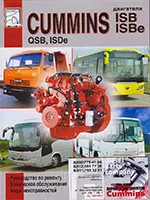
| Автор: | Cummins Inc |
| Год: | 2010 |
| Размер: | 269мБ |
| Страниц: | 300 |
| Формат: | .chm |
| 💾 Скачать |
Руководство по обслуживанию двигателей Cummins предназначено для оказания помощи при определении причин неисправностей, имеющих отношение к двигателю. В нем также содержится описание рекомендованных процедур ремонта. Кроме того, его целью является оказание помощи техническому персоналу при разборке, проверке возможности повторного использования, ремонте и сборке узлов.
Руководство по диагностике и ремонту электронной системы управления двигателями серий ISB и ISBe (4 и 6-цилиндровый)
ISB-ISBe.webp)
| Автор: | Cummins Inc |
| Год: | 2010 |
| Размер: | 63,5мБ |
| Страниц: | 200 |
| Формат: | .chm |
| 💾 Скачать |
В настоящем руководстве содержатся инструкции по диагностике неисправностей и ремонту данного двигателя без снятия его с шасси. Процедуры капитального ремонта узлов и агрегатов изложены в руководстве по капитальному ремонту двигателя. Организация данного руководства построена так, чтобы помочь специалисту пройти по всей цепочке выявления и устранения неисправностей двигателя. Данная инструкция не охватывает отказы машины и оборудования.
Руководство по эксплуатации и техническому обслуживанию КПП ZF 9S 1310 1110
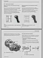
| Автор: | ZF Friedrichshafen AG |
| Год: | 2006 |
| Размер: | 618кБ |
| Страниц: | 26 |
| Формат: | |
| 💾 Скачать |
Ваше транспортное средство оснащено механической коробкой переключения передач серии ZF-ECOMID. Чем лучше Вы будете знать коробку передач Ecomid, тем более экономично Вы сможете с ней ездить. В этом руководстве по эксплуатации содержатся указания, позволяющие Вам полностью использовать технические преимущества ZF коробки передач. Данной КПП оснащаются самосвалы, тягачи и бортовые автомобили: КАМАЗ-65116, КАМАЗ-53504, КАМАЗ-65117, КАМАЗ-65115, КАМАЗ-45143, КАМАЗ-65115 (6059), КАМАЗ-45144 и др.
Каталог запчастей на КПП ZF 9-S-1310 TO с номенклатурными номерами и иллюстрациями.

| Автор: | ZF Friedrichshafen AG |
| Год: | 2014 |
| Размер: | 2мБ |
| Страниц: | 67 |
| Формат: | |
| 💾 Скачать |
Каталог запасных частей на коробку переключения передач ZF 9-S-1310 TO с номенклатурными номерами и иллюстрациями от завода-производителя ZF Friedrichshafen AG.
Технологические карты. Техническое обслуживание седельного тягача КАМАЗ-5490 (Евро-5)
| Автор: | ОАО «КАМАЗ» |
| Год: | 2013 |
| Размер: | 7,1мБ |
| Страниц: | 106 |
| Формат: | |
| 💾 Скачать |
Настоящие технологические карты предназначены для выполнения работ по техническому обслуживанию седельных тягачей КАМАЗ-5490 и их модификаций экологического класса Евро-5 в условиях сервисных технических центров и автотранспортных предприятий в гарантийный и основной периоды эксплуатации. Основным назначением периодического технического обслуживания является выявление и предупреждение неисправностей путем своевременного выполнения контрольно-диагностических, крепежных, регулировочных и смазочно-очистительных работ.
Схема подключения и работы системы Adblue, Common Rail и SCR на КАМАЗе Евро-5
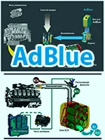
| Автор: | — |
| Год: | 2023 |
| Размер: | 40,3мБ |
| Страниц: | 49 |
| Формат: | |
| 💾 Скачать |
Набор схем-иллюстраций для визуального понимания устройства и подключения систем Adblue, Common Rail и SCR на автомобилях КАМАЗ экологического класса Евро-5. Дополнительная информация по ссылке: Расход AdBlue (мочевины). Инструкция по применению. Системой нетрализации ОГ (AdBlue) оснащаются все автомобили производства АО «КАМАЗ-Инжиниринг»:
• Самосвалы
КАМАЗ-45143,
КАМАЗ-65115 (6058),
КАМАЗ-65115 (6059),
КАМАЗ-45144,
КАМАЗ-6520;
• Седельные тягачи
КАМАЗ-65116,
КАМАЗ-53504;
• Бортовые автомобили
КАМАЗ-65117
• Шасси
КАМАЗ-43118,
КАМАЗ-53605,
КАМАЗ-65115,
КАМАЗ-6520.
Руководство по эксплуатации автомобилей КАМАЗ-43253, -43255, -53229, -55111, -65115, -65116, -65117, -6540
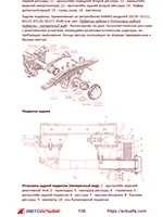
| Автор: | АвтоАльфа |
| Год: | 2018 |
| Размер: | 7,4мБ |
| Страниц: | 241 |
| Формат: | |
| 💾 Скачать |
Руководство по эксплуатации включает в себя технические данные автомобилей КАМАЗ моделей 43253, 43255, 53229, 55111, 65115, 65116, 65117, 6540 и их агрегатов, систем и узлов, рекомендации по эксплуатации, техническому обслуживанию. В приложениях приведены сведения об эксплуатационных материалах, рекомендуемых заводом-изготовителем (топливах, маслах и специальных жидкостях). Предназначено для водителей автомобилей КAMАЗ.
Руководство по текущему и среднему ремонту автомобилей КАМАЗ-4310 (43101) и их модификаций
| Автор: | ОАО «КАМАЗ» |
| Год: | 2003 |
| Размер: | 58,7мБ |
| Страниц: | 273 |
| Формат: | |
| 💾 Скачать |
Руководство предназначено для технического персонала, выполняющего текущий и средний ремонт автомобилей КамАЗ-4310 (43101) и КамАЗ-43105 (43106). В качестве основной модели принят автомобиль КамАЗ-4310. В руководство входят общие указания, операционные карты по замене и ремонту агрегатов, приборов и сборочных единиц.
Каталог деталей и сборочных единиц автомобилей КамАЗ с колесной формулой 6х4. Том I
| Автор: | Политекс |
| Год: | 1993 |
| Размер: | 21,7мБ |
| Страниц: | 413 |
| Формат: | .djvu |
| 💾 Скачать |
Том I. Каталог является справочным техническим пособием при изучении конструкции автомобилей, составление заявок на запасные части, а также может служить пособием при разборке и сборке узлов. Каталог содержит развернутые иллюстрации сборочных единиц, сгруппированных по конструктивному и функциональному признакам.
Каталог деталей и сборочных единиц автомобилей КамАЗ с колесной формулой 6х4. Том II
| Автор: | Политекс |
| Год: | 1993 |
| Размер: | 13,9мБ |
| Страниц: | 254 |
| Формат: | .djvu |
| 💾 Скачать |
Том II. Продолжение сборника справочного пособия по деталям и сборочным единицам КАМАЗ. Материал каталогов подготовлен инженерами научно-технического центра АО «КАМАЗ». Каталог предназначен для работников организаций и предприятий, занимающихся техническим обслуживанием, эксплуатацией и ремонтом автомобилей КамАЗ, а также конструированием новой техники.
Технологические карты по техническому обслуживанию и ремонту автомобилей КамАЗ-5320, -4310, -5511
| Автор: | Политекс |
| Год: | 1992 |
| Размер: | 47,9мБ |
| Страниц: | 238 |
| Формат: | |
| 💾 Скачать |
При разработке технологических карт использованы оборудование, приборы, инструмент и нестандартизированное оборудование, в том числе, разработанное на заводе КамАЗ. Технологические карты содержат нормативы трудоемкости работ, прошли опытную апробацию, являются типовыми. Перечень технологических карт включает ремонт: двигателя, топливной аппаратуры, газовой аппаратуры, электрооборудования, тормозной системы, самосвального механизма, трансмиссии.
🏬 KAMAZ-Центр
ТОО «АвтоТрейд-К» (АТК),
ТОО «КАМАЗ Автосервисный Центр»
С 2005 года группа компаний, включающая представительства автозаводов ПАО «КАМАЗ», АО «КАМАЗ-Инжиниринг», ПАО «НЕФАЗ» и других производителей коммерческого транспорта, осуществляет свою деятельность на рынке Казахстана.
Спектр услуг: Продажа КамАЗ, сервис-центр, сборочная линия спецтехники, региональный склад-магазин запчастей и агрегатов.
🏆 Лидер продаж
ТОО «АвтоТрейд-К» (ATK) — официальный дилер КАМАЗ в Казахстане, который неоднократно получает звание «Лучшего дилера по продаже новых автомобилей КАМАЗ в Казахстане».
Ключевыми факторами успеха компании являются индивидуальный подход к удовлетворению потребностей клиента и привлекательная ценовая политика, выгодная для покупателей.
Будем рады видеть Вас в числе наших клиентов!
+7(707)3607333
info@kamaz.kz
КАМАЗ
2005-02-18
АТК

мкр. Аксай-3А, 62А, офис 36
050000
Алматы
Сертификат дилера ПАО «КАМАЗ» №398/40096783-22067. KAMAZ™ © ТОО «АвтоТрейд-К» 2005-2023 гг.